EP3069431B1 - Uninterruptible power supply control - Google Patents
Uninterruptible power supply controlDownload PDFInfo
- Publication number
- EP3069431B1 EP3069431B1EP13897382.1AEP13897382AEP3069431B1EP 3069431 B1EP3069431 B1EP 3069431B1EP 13897382 AEP13897382 AEP 13897382AEP 3069431 B1EP3069431 B1EP 3069431B1
- Authority
- EP
- European Patent Office
- Prior art keywords
- power
- load
- output
- power source
- voltage
- Prior art date
- Legal status (The legal status is an assumption and is not a legal conclusion. Google has not performed a legal analysis and makes no representation as to the accuracy of the status listed.)
- Active
Links
Images


Classifications
- H—ELECTRICITY
- H02—GENERATION; CONVERSION OR DISTRIBUTION OF ELECTRIC POWER
- H02J—CIRCUIT ARRANGEMENTS OR SYSTEMS FOR SUPPLYING OR DISTRIBUTING ELECTRIC POWER; SYSTEMS FOR STORING ELECTRIC ENERGY
- H02J9/00—Circuit arrangements for emergency or stand-by power supply, e.g. for emergency lighting
- H02J9/04—Circuit arrangements for emergency or stand-by power supply, e.g. for emergency lighting in which the distribution system is disconnected from the normal source and connected to a standby source
- H02J9/06—Circuit arrangements for emergency or stand-by power supply, e.g. for emergency lighting in which the distribution system is disconnected from the normal source and connected to a standby source with automatic change-over, e.g. UPS systems
- H02J9/062—Circuit arrangements for emergency or stand-by power supply, e.g. for emergency lighting in which the distribution system is disconnected from the normal source and connected to a standby source with automatic change-over, e.g. UPS systems for AC powered loads
- H—ELECTRICITY
- H02—GENERATION; CONVERSION OR DISTRIBUTION OF ELECTRIC POWER
- H02J—CIRCUIT ARRANGEMENTS OR SYSTEMS FOR SUPPLYING OR DISTRIBUTING ELECTRIC POWER; SYSTEMS FOR STORING ELECTRIC ENERGY
- H02J9/00—Circuit arrangements for emergency or stand-by power supply, e.g. for emergency lighting
- H02J9/04—Circuit arrangements for emergency or stand-by power supply, e.g. for emergency lighting in which the distribution system is disconnected from the normal source and connected to a standby source
- H02J9/06—Circuit arrangements for emergency or stand-by power supply, e.g. for emergency lighting in which the distribution system is disconnected from the normal source and connected to a standby source with automatic change-over, e.g. UPS systems
- H02J9/061—Circuit arrangements for emergency or stand-by power supply, e.g. for emergency lighting in which the distribution system is disconnected from the normal source and connected to a standby source with automatic change-over, e.g. UPS systems for DC powered loads
- H—ELECTRICITY
- H02—GENERATION; CONVERSION OR DISTRIBUTION OF ELECTRIC POWER
- H02M—APPARATUS FOR CONVERSION BETWEEN AC AND AC, BETWEEN AC AND DC, OR BETWEEN DC AND DC, AND FOR USE WITH MAINS OR SIMILAR POWER SUPPLY SYSTEMS; CONVERSION OF DC OR AC INPUT POWER INTO SURGE OUTPUT POWER; CONTROL OR REGULATION THEREOF
- H02M1/00—Details of apparatus for conversion
- H02M1/42—Circuits or arrangements for compensating for or adjusting power factor in converters or inverters
- H—ELECTRICITY
- H02—GENERATION; CONVERSION OR DISTRIBUTION OF ELECTRIC POWER
- H02M—APPARATUS FOR CONVERSION BETWEEN AC AND AC, BETWEEN AC AND DC, OR BETWEEN DC AND DC, AND FOR USE WITH MAINS OR SIMILAR POWER SUPPLY SYSTEMS; CONVERSION OF DC OR AC INPUT POWER INTO SURGE OUTPUT POWER; CONTROL OR REGULATION THEREOF
- H02M3/00—Conversion of DC power input into DC power output
- H02M3/02—Conversion of DC power input into DC power output without intermediate conversion into AC
- H02M3/04—Conversion of DC power input into DC power output without intermediate conversion into AC by static converters
- H—ELECTRICITY
- H02—GENERATION; CONVERSION OR DISTRIBUTION OF ELECTRIC POWER
- H02M—APPARATUS FOR CONVERSION BETWEEN AC AND AC, BETWEEN AC AND DC, OR BETWEEN DC AND DC, AND FOR USE WITH MAINS OR SIMILAR POWER SUPPLY SYSTEMS; CONVERSION OF DC OR AC INPUT POWER INTO SURGE OUTPUT POWER; CONTROL OR REGULATION THEREOF
- H02M7/00—Conversion of AC power input into DC power output; Conversion of DC power input into AC power output
- H02M7/42—Conversion of DC power input into AC power output without possibility of reversal
- H02M7/44—Conversion of DC power input into AC power output without possibility of reversal by static converters
Definitions
- At least one embodiment of the present inventionrelates generally to control of an uninterruptible power supply.
- Uninterruptible power suppliesare used to provide reliable power to many different types of electronic equipment. Uninterruptible power supplies regulate power provided to a load, and can provide backup power to a load in the event of a loss of primary power, such as during black out or brown out conditions. In addition to providing power to loads, some power is used in the operation of a UPS, reducing the overall efficiency of the UPS.
- JP 2010 124557 A(HITACHI LTD) 3 June 2010 (2010-06-03), JP 08 154347 A (NIPPON BATTERY LTD) 11 June 1996 (1996-06-11), JP 2011 135708 A (HITACHI LTD) 7 July 2011 (2011-07-07)
- At least one aspect of the inventionis directed to an uninterruptible power supply according to claim 1.
- the uninterruptible power supplyincludes a first input configured to receive input power from a first power source, a second input configured to receive input power from a second power source, an output configured to provide output power to a load derived from power from at least one of the first power source and the second power source, a power conversion circuit coupled with the first input, the second input and the output; and a controller coupled with the power conversion circuit.
- the controlleris configured in a first mode of operation to control the power conversion circuit to provide an output voltage of the output power at substantially a first voltage level, and in a second mode of operation to control the power conversion circuit to provide an output voltage of the output power at substantially a second voltage level, with the second voltage level being less than the first voltage level.
- the controllermay be configured, in the second mode of operation, to provide power at the output derived from the second power source,
- the controllermay be configured in the first mode of operation to provide power at the output derived solely from the first power source.
- the controllermay be configured to generate a profile of the load, and to set the second voltage level based on the profile.
- the controllermay be configured to generate the profile of the load by outputting a nominal voltage to the load, changing the nominal voltage by a known amount, and detecting a change in current drawn by the load.
- the second power sourcemay be a battery, and the uninterruptible power supply may include the battery.
- the controllermay be further configured to detect that a capacity of the load has changed by a threshold amount, and in response to the detection, generate an updated profile of the changed load.
- the controllermay be further configured to modify the second voltage based on the updated profile.
- a methodfor controlling an uninterruptible power supply having a first input configured to receive input power from a first power source, a second input configured to receive input power from a second power source, an output configured to provide output power to a load derived from power from at least one of the first power source and the second power source.
- the methodincludes in a first mode of operation, controlling the uninterruptible power supply to provide an output voltage of the output power at substantially a first voltage level, and in a second mode of operation, controlling the uninterruptible power supply to provide an output voltage at substantially a second voltage level, with the second voltage level being less than the first voltage level.
- the methodmay further include providing power at the output derived from the second power source in the second mode of operation.
- the methodmay also include providing power at the output derived solely from the first power source in the first mode of operation, and generating a profile of the load, and setting the second voltage level based on the profile.
- Generating a profilemay include outputting a nominal voltage to the load, changing the nominal voltage by a known amount, and detecting a change in current drawn by the load.
- the second power sourcemay be a battery, and the method may further include providing power to the load solely from the battery in the second mode of operation.
- the methodmay further include detecting that a capacity of the load has changed by a threshold amount, and in response to the detection, generating an updated profile of the changed load, and modifying the second voltage based on the updated profile.
- the UPSmay further include means for detecting a profile of the load and for adjusting the reduced power level based on the profile.
- the second power sourcemay be a battery
- the UPSmay include the battery.
- the UPSmay further include means for detecting a change in a characteristic of the load and updating the profile based on the change.
- An uninterruptible power supplycan include an inverter with an adaptive inverter regulator, which can adjust an output voltage of the inverter to a load to extend runtime of a battery.
- the adjusting of the outputcan be based on a selection of a setting of the adaptive inverter regulator and a profile of the load.
- RMSroot mean square
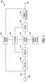
- FIG 1is a functional block diagram 100 depicting an uninterruptible power supply (UPS) 100.
- the uninterruptible power supply 100includes power conversion circuitry such as a circuit breaker/filter 105, a rectifier 110, a control switch 115, a controller 120, a backup power source 125, an inverter 130, a transformer such as an isolation transformer 135, and a bypass switch 140.
- the uninterruptible power supply 100also includes at least one input 145 and output 150.
- the input 145couples an AC power source 155 (e.g., grid power) with the uninterruptible power supply 100
- the output 150couples the uninterruptable power supply 100 with a load.
- AC power source 155e.g., grid power
- the UPS 100 of FIG. 1may be referred to as a double conversion UPS. Aspects described herein are not limited for use with double conversion UPS's, but may be used with other UPS topologies as well.
- the circuit breaker/filter 105receives power from the AC power source 155 via the input 145, filters the input power, and provides filtered power to the rectifier 110.
- the rectifier 110rectifies the filtered power, and provides rectified power to the control switch 115.
- the UPS 100can also include a power factor correction circuit, which can include the rectifier 110 and/or the circuit breaker/filter 105.
- the control switch 115receives the rectified power from the rectifier 110, and receives DC power from the backup power source 125, such as a battery or fuel cell. Under the control of the controller 120, the control switch 115 provides power from the rectifier 110 to the inverter 130.
- the controller 120changes the state of the control switch 115 to couple the rectifier 110 with the inverter 130 when the controller 120 determines that the output power of the rectifier 110 is within a tolerance range. In some embodiments, the controller 120 determines that the output power of the rectifier 110 is outside a tolerance range, for example, during a black out or brown out condition. In this example, the controller 120 operates control of the switch 115 to provide DC power from the backup power source 125 to the inverter 130 directly or via intervening components such as the rectifier 110.
- the uninterruptible power supply 100provides power at the output 150 for a load via the backup power source 125 during failure of the AC power source 155.
- the inverter 130receives DC power output from the rectifier 110 or the backup power source 125, converts the DC power to AC power, and regulates the AC power.
- the uninterruptible power supply 100includes the isolation transformer 135, the inverter 130 provides regulated AC power to the isolation transformer 135.
- the isolation transformer 135increases or decreases the voltage of the AC power output from the inverter 130, and provides isolation between the uninterruptible power supply 100 and a load.
- the bypass switch 140couples the AC power source 155 or the input 145 with the output 150, bypassing at least some components of the uninterruptible power supply 100, (e.g., the rectifier 110) to provide power to the output 150 in a bypass mode of operation.
- the controller 120controls the bypass switch 140 to operate in the bypass mode when the power quality from the AC power source 155 is within a tolerance range, or when there is a failure of the rectifier 110 or other component of the uninterruptible power supply 100.
- the controller 120operates the UPS 100 in various modes, depending on the quality of the input power.
- the UPS 100runs in bypass mode if the quality of the input power is above a first threshold and runs off of the backup power source if the quality of the input power is below a second threshold. It is desirable to operate in bypass mode when possible, as it is the most energy efficient. However, if the quality of the power is too low, the load may be at risk of damage. Further, low quality power or a drop in quality of power may indicate that a grid failure may be more likely to occur, in which case running from the backup power source before the grid fails can prevent damage or power interruption to the load.
- the controller 120includes at least one processor or other logic device. In some embodiments, the controller 120 includes a digital signal processor (DSP). The controller 120 may also include at least one field programmable gate array (FPGA) and an application specific integrated circuit (ASIC), or other hardware, software, firmware, or combinations thereof. In various embodiments, one or more controllers may be part of the UPS 100, or external to but operatively coupled with the UPS 100.
- DSPdigital signal processor
- FPGAfield programmable gate array
- ASICapplication specific integrated circuit
- one or more controllersmay be part of the UPS 100, or external to but operatively coupled with the UPS 100.
- the UPS 100includes adaptive inverter regulation, which can be implemented by the controller 120.
- the adaptive inverter regulationcan have multiple settings to which the user can set a selection of the setting to vary how aggressively the inverter is regulated. For example, the selections of the setting can be one of "off,” “low,” “medium,” and “high.” More or fewer selection settings can be provided. The higher selection can allow for the controller 120 to adjust the inverter 130 to a greater extent in order to potentially extend the runtime of the backup power source 125 for a longer duration.
- the controller 120can extend the runtime of the backup power source 125 by lowering the output voltage of the UPS 100 within parameters that are acceptable to a load coupled to the output 150. The acceptable parameters can be determined by profiling the load, as described further below.
- FIG. 2Ais a functional block diagram of an example mode of operation of a UPS 200, which is similar to UPS 100, and similar components are identified with the same reference numbers.
- FIG. 2Ashows the UPS 200 running in an overload mode of operation, with no adaptive inverter regulation, such as when the setting selection of the adaptive inverter regulation is set to "off.”
- the UPS 200provides power to a load 165, which can include multiple load components. The power is received both from the AC power source 155, as well as the backup power source 125.
- the UPS 200receives 110% of a load capacity of the UPS 200 from the AC power source 155 via the rectifier 110.
- the UPS 200also receives 6% of the load capacity of the UPS 200 from the backup power source 125 via a DC/DC converter 160.
- the UPS 200provides both sources of power, totaling 116% to the inverter 130.
- the adaptive inverter regulationis turned off, and the UPS 200 provides all 116% of the received power to the load 165.
- the backup power sourceis a battery, depending on battery capacity and the power draw of the load, the battery will drain requiring the UPS to enter a bypass operation, or to shut off, if AC power becomes unavailable.
- FIG. 2Bis a functional block diagram of another example mode of operation of the UPS 200.
- FIG. 2Bshows the UPS 200 running in the overload mode of operation as shown in FIG. 2A , but with the adaptive inverter regulation turned on.
- the adaptive inverter regulationis set to "high.”
- “low”can correspond to a 2% reduction of output voltage
- “medium”can correspond to a 4% reduction of output voltage
- “high”can correspond to a 6% reduction of output voltage.
- Other percentagescan be used, along with more or fewer setting selections.
- the adaptive inverter regulationis set to "high,” the inverter 130 can be adjusted to output a voltage that is 6% less than that of FIG. 2A .
- the UPS 200can receive 110% of the load capacity from the AC power source 155, and is able to power the load without using power from the backup power source 125.
- the UPScan continue to power the load without draining a battery used as the backup power source.
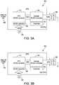
- FIG. 3Ais a functional block diagram of another example mode of operation of the UPS 200.
- FIG. 3Ashows the UPS 200 running in a backup power source mode of operation, receiving no power from the AC power source 155. Rather, the UPS 200 receives 100% of the power for the load from the backup power source 125.
- the UPS 200receives DC power from the backup power source 125 at the DC/DC converter 160.
- the DC/DC converter 160converts the power and provides the power to the inverter 130.
- the UPS 200is running with the adaptive inverter regulation turned off, the inverter 130 converts the DC power to AC power and provides a full 100% voltage to the load 165.
- the backup power source 125As the backup power source 125 provides power to the load 165 and depletes, the backup power source will have a specific runtime before the backup power source 125 runs out of power.
- the specific runtimewill depend on the amount of power initially stored in the backup power source 125, as well as the amount of power drawn by the load 165.
- FIG. 3Bis a functional block diagram of another example mode of operation of the UPS 200.
- FIG. 3Bshows the UPS 200 running in the backup power source mode of operation as in FIG. 3A , but with the adaptive inverter regulation set to "high.”
- a "high" settingresults in a 6% decrease in output voltage.
- such a decrease in output voltagedoes not compromise safe operation of the load 165.
- such a decreasecan result in a corresponding decrease in current drawn by the load 165.
- the 6% decrease in output voltagecan result in a 6% decrease in current drawn by the load 165, so that the runtime of the backup power source 125 can increase by 12% or more.
- the UPS 200can generate a profile of the load 165 to determine the increase in runtime of the backup power source 125 that would correspond to each of the settings of the adaptive inverter regulation.
- the UPS 200can generate the load profile by outputting a nominal voltage to the load 165.
- the UPS 100can then change the voltage output to the load 165 by a known amount, and then measure the change in current produced by such a change in voltage.
- the load profilecan provide information related to whether the load 165 is active or passive or a mix of both.
- the load profilecan also be used to calculate the battery runtime based on the adjustments made to the inverter 130 and the output voltage.
- the profile of the load 165can also be used to configure each of the selection settings.
- the UPS 200can determine a maximum safe reduction of RMS input voltage to the load 165 and change the percentage adjustment of each of the selection settings based on the maximum safe reduction.
- the UPS 200can set the "high" setting to be half the maximum safe reduction and scale the other settings accordingly. For instance, if the load 165 can safely receive an RMS voltage of 10% less, the UPS 200 can set the "high” setting for the adaptive inverter regulation to be 5%, and correspondingly, the "medium” setting to be 3% and the "low” setting to be 1.5%.
- Other appropriate algorithmscan be used to set the selection settings, such as having a minimum percentage for the "low” setting or other such factors.
- the percentages of the settingscan be configured by the user, either by manually entering the settings in the UPS or from a remote computer over a network interface of the UPS 200.
- the profile of the load 165can be affected by an output current limit set on the UPS 200.
- the load 165includes active load components, reducing the output voltage of the UPS 200 can result in an increase in current drawn by the load 165.
- the UPS 200can generate a load profile that takes the output current limit into consideration and/or configure the percentages of the selection settings of the adaptive inverter regulation to maximize runtime of the backup power source 125 without exceeding the UPS output current limit.
- the load profilecan be used to determine that the increase in runtime of the backup power source 125 is below a threshold. For example, if the load 165 includes primarily active load components, the increase in runtime of the backup power source 125 by decreasing the output voltage can be minimal.
- a thresholdsuch as 1%, can be used to compare the expected runtime increase. If the expected runtime increase does not meet the threshold, in some embodiments, the UPS 100 can suspend the adaptive inverter regulation.
- the backup power source 125can be replaced with a smaller backup power source, such as a smaller battery. For example, if a threshold amount of runtime is desired for the load 165 from the backup power source 125, if the expected runtime is extended enough based on the load profile, a smaller battery can be used that still meets the threshold amount of runtime, allowing the UPS 200 to utilize less space and/or cost less.
- FIG. 4is a flow chart of an example process 400 of the UPS 200.
- the processstarts.
- the UPS 100determines whether the adaptive inverter regulation is active.
- the adaptive inverter regulationcan be inactive for various reasons, such as the selection setting set to "off," or from expected runtime increases not meeting a threshold, as described earlier. If the adaptive inverter regulation is inactive, the process 400 can exit at act 420. If the adaptive inverter regulation is active, the UPS 200 determines whether the UPS 200 is running in battery operation at act 406.
- the battery operationcan include any mode of operation of the UPS 200 where power is drawn from the backup power source 125, whether power is also being received from the AC power source 155 or not.
- the process 400exits at act 420. If the UPS 200 is running in battery operation, the UPS 100 determines whether a load profile has been performed at act 408. If the load profile has not been performed, the UPS 200 generates a load profile at act 410.
- the load profilecan be generated as described above to determine expected battery runtime increases as well as to determine percentage decreases in output voltage for each of the selection settings.
- the UPS 100can determine whether the load 165 coupled to the UPS 200 has changed by more than a threshold amount. For example, if the threshold amount is 10%, the UPS 200 can determine whether a capacity of the load 165 has changed by 10% or more. If the load 165 has changed by more than the threshold amount, the UPS 200 can reset the load profile and profile the load again.
- a threshold amountis 10%
- the UPS 200can determine whether a capacity of the load 165 has changed by 10% or more. If the load 165 has changed by more than the threshold amount, the UPS 200 can reset the load profile and profile the load again.
- the UPS 200receives the selection of the adaptive inverter regulation setting at act 416. Based on the selection of the setting and the profile of the load, the UPS 200 adjusts the output RMS voltage of the inverter 130 at act 418, as described above. At act 420, the process 400 exits.
- UPS'sin accordance with embodiments may operate as single phase or multiple phase devices and at a variety of voltage levels.
Landscapes
- Engineering & Computer Science (AREA)
- Power Engineering (AREA)
- Business, Economics & Management (AREA)
- Emergency Management (AREA)
- Inverter Devices (AREA)
- Stand-By Power Supply Arrangements (AREA)
Description
- At least one embodiment of the present invention relates generally to control of an uninterruptible power supply.
- Uninterruptible power supplies (UPSs) are used to provide reliable power to many different types of electronic equipment. Uninterruptible power supplies regulate power provided to a load, and can provide backup power to a load in the event of a loss of primary power, such as during black out or brown out conditions. In addition to providing power to loads, some power is used in the operation of a UPS, reducing the overall efficiency of the UPS.
- The following published patent applications deal with the improvement of the efficiency of UPS:
JP 2010 124557 A JP 08 154347 A JP 2011 135708 A - At least one aspect of the invention is directed to an uninterruptible power supply according to claim 1.
- The uninterruptible power supply includes a first input configured to receive input power from a first power source, a second input configured to receive input power from a second power source, an output configured to provide output power to a load derived from power from at least one of the first power source and the second power source, a power conversion circuit coupled with the first input, the second input and the output; and a controller coupled with the power conversion circuit. The controller is configured in a first mode of operation to control the power conversion circuit to provide an output voltage of the output power at substantially a first voltage level, and in a second mode of operation to control the power conversion circuit to provide an output voltage of the output power at substantially a second voltage level, with the second voltage level being less than the first voltage level.
- In the uninterruptible power supply, the controller may be configured, in the second mode of operation, to provide power at the output derived from the second power source, The controller may be configured in the first mode of operation to provide power at the output derived solely from the first power source. The controller may be configured to generate a profile of the load, and to set the second voltage level based on the profile. The controller may be configured to generate the profile of the load by outputting a nominal voltage to the load, changing the nominal voltage by a known amount, and detecting a change in current drawn by the load. The second power source may be a battery, and the uninterruptible power supply may include the battery. The controller may be further configured to detect that a capacity of the load has changed by a threshold amount, and in response to the detection, generate an updated profile of the changed load. The controller may be further configured to modify the second voltage based on the updated profile.
- In another aspect, a method according to claim 7 is provided for controlling an uninterruptible power supply having a first input configured to receive input power from a first power source, a second input configured to receive input power from a second power source, an output configured to provide output power to a load derived from power from at least one of the first power source and the second power source. The method includes in a first mode of operation, controlling the uninterruptible power supply to provide an output voltage of the output power at substantially a first voltage level, and in a second mode of operation, controlling the uninterruptible power supply to provide an output voltage at substantially a second voltage level, with the second voltage level being less than the first voltage level.
- The method may further include providing power at the output derived from the second power source in the second mode of operation. The method may also include providing power at the output derived solely from the first power source in the first mode of operation, and generating a profile of the load, and setting the second voltage level based on the profile. Generating a profile may include outputting a nominal voltage to the load, changing the nominal voltage by a known amount, and detecting a change in current drawn by the load. The second power source may be a battery, and the method may further include providing power to the load solely from the battery in the second mode of operation. The method may further include detecting that a capacity of the load has changed by a threshold amount, and in response to the detection, generating an updated profile of the changed load, and modifying the second voltage based on the updated profile.
- The UPS may further include means for detecting a profile of the load and for adjusting the reduced power level based on the profile. In the UPS, the second power source may be a battery, and the UPS may include the battery. The UPS may further include means for detecting a change in a characteristic of the load and updating the profile based on the change.
- The accompanying drawings are not intended to be drawn to scale. In the drawings, each identical or nearly identical component that is illustrated in various figures is represented by a like numeral. For purposes of clarity, not every component may be labeled in every drawing. In the drawings:
FIG. 1 is a functional block diagram depicting an example uninterruptible power supply in accordance with an embodiment;FIG. 2A is a functional block diagram depicting an example uninterruptible power supply in accordance with an embodiment;FIG. 2B is a functional block diagram depicting an example uninterruptible power supply in accordance with an embodiment;FIG. 3A is a functional block diagram depicting an example uninterruptible power supply in accordance with an embodiment;FIG. 3B is a functional block diagram depicting an example uninterruptible power supply in accordance with an embodiment; andFIG. 4 is a flow chart showing an example process in accordance with an embodiment.- An uninterruptible power supply (UPS) can include an inverter with an adaptive inverter regulator, which can adjust an output voltage of the inverter to a load to extend runtime of a battery. The adjusting of the output can be based on a selection of a setting of the adaptive inverter regulator and a profile of the load. By lowering the output root mean square (RMS) voltage of the inverter within an acceptable threshold of the load, the runtime of the battery can be extended.
- Examples of the methods and apparatuses discussed herein are not limited in application to the details of construction and the arrangement of components set forth in the following description or illustrated in the accompanying drawings. The methods and apparatuses are capable of implementation in other examples and of being practiced or of being carried out in various ways. Examples of specific implementations are provided herein for illustrative purposes only and are not intended to be limiting. In particular, acts, components, elements and features discussed in connection with any one or more examples are not intended to be excluded from a similar role in any other examples.
- Also, the phraseology and terminology used herein is for the purpose of description and should not be regarded as limiting. Any references to examples, components, elements or acts of the systems and methods herein referred to in the singular may also embrace examples including a plurality, and any references in plural to any example, component, element or act herein may also embrace examples including only a singularity. References in the singular or plural form are not intended to limit the presently disclosed systems or methods, their components, acts, or elements. The use herein of "including," "comprising," "having," "containing," "involving," and variations thereof is meant to encompass the items listed thereafter and equivalents thereof as well as additional items. References to "or" may be construed as inclusive so that any terms described using "or" may indicate any of a single, more than one, and all of the described terms.
FIG 1 is a functional block diagram 100 depicting an uninterruptible power supply (UPS) 100. Theuninterruptible power supply 100 includes power conversion circuitry such as a circuit breaker/filter 105, arectifier 110, acontrol switch 115, acontroller 120, abackup power source 125, aninverter 130, a transformer such as anisolation transformer 135, and abypass switch 140. Theuninterruptible power supply 100 also includes at least oneinput 145 andoutput 150. Theinput 145 couples an AC power source 155 (e.g., grid power) with theuninterruptible power supply 100, and theoutput 150 couples theuninterruptable power supply 100 with a load.- The UPS 100 of
FIG. 1 may be referred to as a double conversion UPS. Aspects described herein are not limited for use with double conversion UPS's, but may be used with other UPS topologies as well. - In one embodiment, the circuit breaker/
filter 105 receives power from theAC power source 155 via theinput 145, filters the input power, and provides filtered power to therectifier 110. Therectifier 110 rectifies the filtered power, and provides rectified power to thecontrol switch 115. The UPS 100 can also include a power factor correction circuit, which can include therectifier 110 and/or the circuit breaker/filter 105. Thecontrol switch 115 receives the rectified power from therectifier 110, and receives DC power from thebackup power source 125, such as a battery or fuel cell. Under the control of thecontroller 120, thecontrol switch 115 provides power from therectifier 110 to theinverter 130. For example, thecontroller 120 changes the state of thecontrol switch 115 to couple therectifier 110 with theinverter 130 when thecontroller 120 determines that the output power of therectifier 110 is within a tolerance range. In some embodiments, thecontroller 120 determines that the output power of therectifier 110 is outside a tolerance range, for example, during a black out or brown out condition. In this example, thecontroller 120 operates control of theswitch 115 to provide DC power from thebackup power source 125 to theinverter 130 directly or via intervening components such as therectifier 110. Theuninterruptible power supply 100 provides power at theoutput 150 for a load via thebackup power source 125 during failure of theAC power source 155. - The
inverter 130 receives DC power output from therectifier 110 or thebackup power source 125, converts the DC power to AC power, and regulates the AC power. In some embodiments where theuninterruptible power supply 100 includes theisolation transformer 135, theinverter 130 provides regulated AC power to theisolation transformer 135. Theisolation transformer 135 increases or decreases the voltage of the AC power output from theinverter 130, and provides isolation between theuninterruptible power supply 100 and a load. - In some embodiments, the
bypass switch 140 couples theAC power source 155 or theinput 145 with theoutput 150, bypassing at least some components of theuninterruptible power supply 100, (e.g., the rectifier 110) to provide power to theoutput 150 in a bypass mode of operation. For example, thecontroller 120 controls thebypass switch 140 to operate in the bypass mode when the power quality from theAC power source 155 is within a tolerance range, or when there is a failure of therectifier 110 or other component of theuninterruptible power supply 100. In some embodiments, thecontroller 120 operates theUPS 100 in various modes, depending on the quality of the input power. For example, theUPS 100 runs in bypass mode if the quality of the input power is above a first threshold and runs off of the backup power source if the quality of the input power is below a second threshold. It is desirable to operate in bypass mode when possible, as it is the most energy efficient. However, if the quality of the power is too low, the load may be at risk of damage. Further, low quality power or a drop in quality of power may indicate that a grid failure may be more likely to occur, in which case running from the backup power source before the grid fails can prevent damage or power interruption to the load. - In some embodiments, the
controller 120 includes at least one processor or other logic device. In some embodiments, thecontroller 120 includes a digital signal processor (DSP). Thecontroller 120 may also include at least one field programmable gate array (FPGA) and an application specific integrated circuit (ASIC), or other hardware, software, firmware, or combinations thereof. In various embodiments, one or more controllers may be part of theUPS 100, or external to but operatively coupled with theUPS 100. - The
UPS 100 includes adaptive inverter regulation, which can be implemented by thecontroller 120. The adaptive inverter regulation can have multiple settings to which the user can set a selection of the setting to vary how aggressively the inverter is regulated. For example, the selections of the setting can be one of "off," "low," "medium," and "high." More or fewer selection settings can be provided. The higher selection can allow for thecontroller 120 to adjust theinverter 130 to a greater extent in order to potentially extend the runtime of thebackup power source 125 for a longer duration. Thecontroller 120 can extend the runtime of thebackup power source 125 by lowering the output voltage of theUPS 100 within parameters that are acceptable to a load coupled to theoutput 150. The acceptable parameters can be determined by profiling the load, as described further below. FIG. 2A is a functional block diagram of an example mode of operation of aUPS 200, which is similar toUPS 100, and similar components are identified with the same reference numbers.FIG. 2A shows theUPS 200 running in an overload mode of operation, with no adaptive inverter regulation, such as when the setting selection of the adaptive inverter regulation is set to "off." TheUPS 200 provides power to aload 165, which can include multiple load components. The power is received both from theAC power source 155, as well as thebackup power source 125. As theUPS 200 is running in an overload mode, theUPS 200 receives 110% of a load capacity of theUPS 200 from theAC power source 155 via therectifier 110. TheUPS 200 also receives 6% of the load capacity of theUPS 200 from thebackup power source 125 via a DC/DC converter 160. TheUPS 200 provides both sources of power, totaling 116% to theinverter 130. In the Example ofFIG 2A , the adaptive inverter regulation is turned off, and theUPS 200 provides all 116% of the received power to theload 165. In this example, at some point, when the backup power source is a battery, depending on battery capacity and the power draw of the load, the battery will drain requiring the UPS to enter a bypass operation, or to shut off, if AC power becomes unavailable.FIG. 2B is a functional block diagram of another example mode of operation of theUPS 200.FIG. 2B shows theUPS 200 running in the overload mode of operation as shown inFIG. 2A , but with the adaptive inverter regulation turned on. In this example, the adaptive inverter regulation is set to "high." In some embodiments, "low" can correspond to a 2% reduction of output voltage, "medium" can correspond to a 4% reduction of output voltage, and "high" can correspond to a 6% reduction of output voltage. Other percentages can be used, along with more or fewer setting selections. As the adaptive inverter regulation is set to "high," theinverter 130 can be adjusted to output a voltage that is 6% less than that ofFIG. 2A . Thus, theUPS 200 can receive 110% of the load capacity from theAC power source 155, and is able to power the load without using power from thebackup power source 125. In the Example ofFIG. 2B , the UPS can continue to power the load without draining a battery used as the backup power source.FIG. 3A is a functional block diagram of another example mode of operation of theUPS 200.FIG. 3A shows theUPS 200 running in a backup power source mode of operation, receiving no power from theAC power source 155. Rather, theUPS 200 receives 100% of the power for the load from thebackup power source 125. TheUPS 200 receives DC power from thebackup power source 125 at the DC/DC converter 160. The DC/DC converter 160 converts the power and provides the power to theinverter 130. As theUPS 200 is running with the adaptive inverter regulation turned off, theinverter 130 converts the DC power to AC power and provides a full 100% voltage to theload 165. As thebackup power source 125 provides power to theload 165 and depletes, the backup power source will have a specific runtime before thebackup power source 125 runs out of power. The specific runtime will depend on the amount of power initially stored in thebackup power source 125, as well as the amount of power drawn by theload 165.FIG. 3B is a functional block diagram of another example mode of operation of theUPS 200.FIG. 3B shows theUPS 200 running in the backup power source mode of operation as inFIG. 3A , but with the adaptive inverter regulation set to "high." In some embodiments, a "high" setting results in a 6% decrease in output voltage. Depending on the type of load, such a decrease in output voltage does not compromise safe operation of theload 165. Also depending on the type of load, such a decrease can result in a corresponding decrease in current drawn by theload 165. For example, for a passive load, the 6% decrease in output voltage can result in a 6% decrease in current drawn by theload 165, so that the runtime of thebackup power source 125 can increase by 12% or more.- In one embodiment, the
UPS 200 can generate a profile of theload 165 to determine the increase in runtime of thebackup power source 125 that would correspond to each of the settings of the adaptive inverter regulation. TheUPS 200 can generate the load profile by outputting a nominal voltage to theload 165. TheUPS 100 can then change the voltage output to theload 165 by a known amount, and then measure the change in current produced by such a change in voltage. The load profile can provide information related to whether theload 165 is active or passive or a mix of both. The load profile can also be used to calculate the battery runtime based on the adjustments made to theinverter 130 and the output voltage. - The profile of the
load 165 can also be used to configure each of the selection settings. For example, theUPS 200 can determine a maximum safe reduction of RMS input voltage to theload 165 and change the percentage adjustment of each of the selection settings based on the maximum safe reduction. In some embodiments, theUPS 200 can set the "high" setting to be half the maximum safe reduction and scale the other settings accordingly. For instance, if theload 165 can safely receive an RMS voltage of 10% less, theUPS 200 can set the "high" setting for the adaptive inverter regulation to be 5%, and correspondingly, the "medium" setting to be 3% and the "low" setting to be 1.5%. Other appropriate algorithms can be used to set the selection settings, such as having a minimum percentage for the "low" setting or other such factors. Alternatively or additionally, the percentages of the settings can be configured by the user, either by manually entering the settings in the UPS or from a remote computer over a network interface of theUPS 200. - In some embodiments, the profile of the
load 165 can be affected by an output current limit set on theUPS 200. For example, if theload 165 includes active load components, reducing the output voltage of theUPS 200 can result in an increase in current drawn by theload 165. TheUPS 200 can generate a load profile that takes the output current limit into consideration and/or configure the percentages of the selection settings of the adaptive inverter regulation to maximize runtime of thebackup power source 125 without exceeding the UPS output current limit. - In some embodiments, the load profile can be used to determine that the increase in runtime of the
backup power source 125 is below a threshold. For example, if theload 165 includes primarily active load components, the increase in runtime of thebackup power source 125 by decreasing the output voltage can be minimal. A threshold, such as 1%, can be used to compare the expected runtime increase. If the expected runtime increase does not meet the threshold, in some embodiments, theUPS 100 can suspend the adaptive inverter regulation. - In some embodiments, based on the load profile and the expected runtime of the
backup power source 125, thebackup power source 125 can be replaced with a smaller backup power source, such as a smaller battery. For example, if a threshold amount of runtime is desired for theload 165 from thebackup power source 125, if the expected runtime is extended enough based on the load profile, a smaller battery can be used that still meets the threshold amount of runtime, allowing theUPS 200 to utilize less space and/or cost less. FIG. 4 is a flow chart of anexample process 400 of theUPS 200. Atact 402, the process starts. Atact 404, theUPS 100 determines whether the adaptive inverter regulation is active. The adaptive inverter regulation can be inactive for various reasons, such as the selection setting set to "off," or from expected runtime increases not meeting a threshold, as described earlier. If the adaptive inverter regulation is inactive, theprocess 400 can exit atact 420. If the adaptive inverter regulation is active, theUPS 200 determines whether theUPS 200 is running in battery operation atact 406. The battery operation can include any mode of operation of theUPS 200 where power is drawn from thebackup power source 125, whether power is also being received from theAC power source 155 or not.- If the
UPS 200 is not running in battery operation, theprocess 400 exits atact 420. If theUPS 200 is running in battery operation, theUPS 100 determines whether a load profile has been performed atact 408. If the load profile has not been performed, theUPS 200 generates a load profile atact 410. The load profile can be generated as described above to determine expected battery runtime increases as well as to determine percentage decreases in output voltage for each of the selection settings. - If the load profile has been performed, the
UPS 100 can determine whether theload 165 coupled to theUPS 200 has changed by more than a threshold amount. For example, if the threshold amount is 10%, theUPS 200 can determine whether a capacity of theload 165 has changed by 10% or more. If theload 165 has changed by more than the threshold amount, theUPS 200 can reset the load profile and profile the load again. - If the load has not changed by at least the threshold amount, the
UPS 200 receives the selection of the adaptive inverter regulation setting atact 416. Based on the selection of the setting and the profile of the load, theUPS 200 adjusts the output RMS voltage of theinverter 130 atact 418, as described above. Atact 420, theprocess 400 exits. - At least some embodiments described herein may be used with several different types of UPS's, include online, offline, line interactive, double conversion, and those utilizing delta converters, to provide extended runtime capabilities while still providing sufficient output power for critical loads. UPS's in accordance with embodiments may operate as single phase or multiple phase devices and at a variety of voltage levels.
Claims (13)
- An uninterruptible power supply (100), comprising:a first input configured to receive input power from a first power source;a second input configured to receive input power from a second power source;an output configured to provide output power to a load derived from power from at least one of the first power source and the second power source;a power conversion circuit coupled with the first input, the second input and the output; anda controller (120) coupled with the power conversion circuit, the controller configured to:in a first mode of operation, control the power conversion circuit to provide an output voltage of the output power at substantially a first voltage level;generate a profile of the load;in a second mode of operation, control the power conversion circuit to provide an output voltage of the output power at substantially a second voltage level, with the second voltage level being less than the first voltage level and based on the profile of the load;detect that a capacity of the load has changed by a threshold amount; andin response to the detection, generate an updated profile of the changed load.
- The uninterruptible power supply of claim 1, wherein the controller (120) is configured, in the second mode of operation, to provide power at the output derived from the second power source
- The uninterruptible power supply of claim 2, wherein the controller (120) is configured in the first mode of operation to provide power at the output derived solely from the first power source.
- The uninterruptible power supply of claim 1, wherein the controller (120) is configured to generate the profile of the load by:outputting a nominal voltage to the load;changing the nominal voltage by a known amount; anddetecting a change in current drawn by the load.
- The uninterruptible power supply of claim 1, wherein the second power source is a battery, and wherein the uninterruptible power supply includes the battery.
- The uninterruptible power supply of claim 1, wherein the controller (120) is further configured to modify the second voltage based on the updated profile.
- A method for controlling an uninterruptible power supply (100) having a first input configured to receive input power from a first power source, a second input configured to receive input power from a second power source, an output configured to provide output power to a load derived from power from at least one of the first power source and the second power source, the method comprising:in a first mode of operation, controlling the uninterruptible power supply to provide an output voltage of the output power at substantially a first voltage level;generating a profile of the load;in a second mode of operation, controlling the uninterruptible power supply to provide an output voltage at substantially a second voltage level, with the second voltage level being less than the first voltage level;setting the second voltage level based on the generated profile;detecting that a capacity of the load has changed by a threshold amount; andin response to the detection; generating an updated profile of the changed load..
- The method of claim 7, further comprising providing power at the output derived from the second power source in the second mode of operation.
- The method of claim 7, wherein generating a profile includes:outputting a nominal voltage to the load;changing the nominal voltage by a known amount; anddetecting a change in current drawn by the load.
- The method of claim 7, wherein the second power source is a battery, and wherein the method further includes providing power to the load solely from the battery in the second mode of operation.
- The method of claim 9, further comprising modifying the second voltage based on the updated profile.
- The uninterruptible power supply (100) of claim 1, wherein the output is configured to provide AC output power to the load.
- The method of claim 7, wherein controlling the uninterruptible power supply (100) to provide the output voltage at the first and second voltage levels further involves providing AC output voltages at the first and second voltage levels.
Applications Claiming Priority (1)
| Application Number | Priority Date | Filing Date | Title |
|---|---|---|---|
| PCT/US2013/070039WO2015072999A1 (en) | 2013-11-14 | 2013-11-14 | Uninterruptible power supply control |
Publications (3)
| Publication Number | Publication Date |
|---|---|
| EP3069431A1 EP3069431A1 (en) | 2016-09-21 |
| EP3069431A4 EP3069431A4 (en) | 2017-08-02 |
| EP3069431B1true EP3069431B1 (en) | 2019-07-17 |
Family
ID=53057782
Family Applications (1)
| Application Number | Title | Priority Date | Filing Date |
|---|---|---|---|
| EP13897382.1AActiveEP3069431B1 (en) | 2013-11-14 | 2013-11-14 | Uninterruptible power supply control |
Country Status (5)
| Country | Link |
|---|---|
| US (1) | US9882423B2 (en) |
| EP (1) | EP3069431B1 (en) |
| CN (1) | CN105723588B (en) |
| DK (1) | DK3069431T3 (en) |
| WO (1) | WO2015072999A1 (en) |
Families Citing this family (11)
| Publication number | Priority date | Publication date | Assignee | Title |
|---|---|---|---|---|
| US10523027B2 (en)* | 2014-06-03 | 2019-12-31 | Murata Manufacturing Co., Ltd. | Power supply apparatus and power supply method |
| DE102015104654B3 (en)* | 2014-10-20 | 2016-02-04 | Fujitsu Technology Solutions Intellectual Property Gmbh | Energy supply arrangement and its use |
| US9769948B2 (en) | 2014-12-10 | 2017-09-19 | Eaton Corporation | Modular uninterruptible power supply apparatus and methods of operating same |
| US20160202749A1 (en)* | 2015-01-13 | 2016-07-14 | Netlist, Inc. | System and method for determining charge of a secondary power supply for a memory system |
| US20190067986A1 (en)* | 2017-08-25 | 2019-02-28 | Saudi Arabian Oil Company | Distributed Energy Storage Systems |
| US11258295B2 (en) | 2019-06-10 | 2022-02-22 | C&C Power, Inc. | Maintenance bypass assembly for uninterruptable power supply |
| US11223228B2 (en)* | 2019-06-20 | 2022-01-11 | Schneider Electric It Corporation | Artificially intelligent uninterruptible power supply |
| US11349335B2 (en)* | 2019-11-25 | 2022-05-31 | Cyber Power Systems, Inc. | Power supplying device |
| DE102020101438A1 (en)* | 2020-01-22 | 2021-07-22 | Connaught Electronics Ltd. | Electronic computing device for a motor vehicle with a circuit which is supplied with a voltage via a control device outside the computing device, arrangement and method |
| US11888340B2 (en)* | 2020-12-04 | 2024-01-30 | Schneider Electric It Corporation | Method to enhance the life of a lithium battery |
| US12051940B2 (en)* | 2022-12-09 | 2024-07-30 | Google Llc | Timing determination for UPS power transfer |
Family Cites Families (30)
| Publication number | Priority date | Publication date | Assignee | Title |
|---|---|---|---|---|
| US5315533A (en) | 1991-05-17 | 1994-05-24 | Best Power Technology, Inc. | Back-up uninterruptible power system |
| JPH08154347A (en)* | 1994-11-25 | 1996-06-11 | Japan Storage Battery Co Ltd | Uninterruptible ac power supply apparatus |
| US5612580A (en) | 1995-10-10 | 1997-03-18 | Northrop Grumman Corporation | Uninterruptible power system |
| US5982652A (en) | 1998-07-14 | 1999-11-09 | American Power Conversion | Method and apparatus for providing uninterruptible power using a power controller and a redundant power controller |
| US6191500B1 (en)* | 1998-11-06 | 2001-02-20 | Kling Lindquist Partnership, Inc. | System and method for providing an uninterruptible power supply to a critical load |
| US6268665B1 (en)* | 1999-05-10 | 2001-07-31 | Mutipower, Inc. | Testing battery power source of uninterruptible power supply |
| US6630752B2 (en)* | 2001-09-12 | 2003-10-07 | Qualmag, Inc. | Uninterruptible transfer switch |
| US7259477B2 (en) | 2003-08-15 | 2007-08-21 | American Power Conversion Corporation | Uninterruptible power supply |
| US6906435B1 (en)* | 2003-12-02 | 2005-06-14 | Handsun Electronic Enterprise Co., Ltd. | Uninterruptible power system with two current conversion units |
| US7446433B2 (en) | 2004-01-23 | 2008-11-04 | American Power Conversion Corporation | Methods and apparatus for providing uninterruptible power |
| US7432615B2 (en)* | 2004-01-29 | 2008-10-07 | American Power Conversion Corporation | Uninterruptable power supply system and method |
| US7050312B2 (en) | 2004-03-09 | 2006-05-23 | Eaton Power Quality Corporation | Multi-mode uninterruptible power supplies and methods of operation thereof |
| US7456518B2 (en)* | 2004-08-31 | 2008-11-25 | American Power Conversion Corporation | Method and apparatus for providing uninterruptible power |
| US7737580B2 (en)* | 2004-08-31 | 2010-06-15 | American Power Conversion Corporation | Method and apparatus for providing uninterruptible power |
| US20060072283A1 (en)* | 2004-09-27 | 2006-04-06 | Thompson James G | Uninterruptible power supply with integral applications processor |
| US7705489B2 (en)* | 2006-09-08 | 2010-04-27 | American Power Conversion Corporation | Method and apparatus for providing uninterruptible power |
| US8212401B2 (en)* | 2007-08-03 | 2012-07-03 | Stratascale, Inc. | Redundant isolation and bypass of critical power equipment |
| NO327851B1 (en)* | 2008-08-01 | 2009-10-05 | Therm Tech As | Battery charger and power supply using alternative energy. |
| GB0818174D0 (en)* | 2008-10-03 | 2008-11-12 | Leaneco Aps | Emergency power supply apparatus |
| JP5171567B2 (en)* | 2008-11-18 | 2013-03-27 | 株式会社日立製作所 | Uninterruptible power system |
| WO2010126615A1 (en) | 2009-04-30 | 2010-11-04 | Green Plug, Inc. | Multi-functional bi-directional communication and bias power architecture for power supply control |
| US8232760B2 (en)* | 2009-06-11 | 2012-07-31 | Easton Corporation | System and method of dynamic regulation of real power to a load |
| US9148083B2 (en)* | 2009-06-11 | 2015-09-29 | Eaton Corporation | System and method of dynamic regulation of real power to a load |
| US8203236B2 (en)* | 2009-11-18 | 2012-06-19 | GM Global Technology Operations LLC | Dual voltage-source inverter system and method |
| JP2011135708A (en)* | 2009-12-25 | 2011-07-07 | Hitachi Ltd | Power supply system |
| US8374012B2 (en)* | 2010-06-10 | 2013-02-12 | Carefusion 303, Inc. | Phase-controlled uninterruptible power supply |
| US8803361B2 (en)* | 2011-01-19 | 2014-08-12 | Schneider Electric It Corporation | Apparatus and method for providing uninterruptible power |
| US9362781B2 (en)* | 2012-09-14 | 2016-06-07 | Chloride Srl | Uninterruptible power supply system with fast transfer for undervoltage source line failures |
| US20140197689A1 (en)* | 2013-01-14 | 2014-07-17 | Zippy Technology Corp. | Power supply providing longer lifespan of battery modules |
| US9634512B1 (en)* | 2013-12-03 | 2017-04-25 | Google Inc. | Battery backup with bi-directional converter |
- 2013
- 2013-11-14DKDK13897382.1Tpatent/DK3069431T3/enactive
- 2013-11-14WOPCT/US2013/070039patent/WO2015072999A1/enactiveApplication Filing
- 2013-11-14USUS15/035,644patent/US9882423B2/enactiveActive
- 2013-11-14EPEP13897382.1Apatent/EP3069431B1/enactiveActive
- 2013-11-14CNCN201380080926.XApatent/CN105723588B/enactiveActive
Non-Patent Citations (1)
| Title |
|---|
| None* |
Also Published As
| Publication number | Publication date |
|---|---|
| DK3069431T3 (en) | 2019-10-07 |
| EP3069431A4 (en) | 2017-08-02 |
| WO2015072999A1 (en) | 2015-05-21 |
| CN105723588A (en) | 2016-06-29 |
| CN105723588B (en) | 2019-04-23 |
| US20160276870A1 (en) | 2016-09-22 |
| EP3069431A1 (en) | 2016-09-21 |
| US9882423B2 (en) | 2018-01-30 |
Similar Documents
| Publication | Publication Date | Title |
|---|---|---|
| EP3069431B1 (en) | Uninterruptible power supply control | |
| CN107888087B (en) | Power supply including logic circuit | |
| EP2174400B1 (en) | Adjustable battery charger for ups | |
| US9929592B2 (en) | UPS sensitivity of power status parameter adjustment setting method | |
| CN110999012B (en) | Multi-mode uninterruptible power supply system with improved power saving mode | |
| US10148123B2 (en) | Uninterruptible power supply control | |
| JP2015154552A (en) | Power source apparatus | |
| KR20160018266A (en) | System for converting power and method for controlling the system | |
| US9941738B2 (en) | Dynamic DC link voltage control | |
| CN118659681A (en) | A power transformation system, a power converter and a busbar capacitance reduction method | |
| JP2015050913A (en) | Power control system | |
| CN106464002B (en) | Uninterruptible power supply system and operation method thereof | |
| US11258297B2 (en) | Inverter control strategy for a transient heavy load | |
| JP6289123B2 (en) | Power generation system | |
| JP2018170931A (en) | Power conversion apparatus and power conversion system | |
| JP2006067673A (en) | Power supply | |
| US10923750B2 (en) | DC voltage brownout protection for parallel-connected fuel-cell power plants in islanded mode | |
| WO2018179712A1 (en) | Power conversion device, power conversion system | |
| AU2008284151B2 (en) | Adjustable battery charger for UPS | |
| JP2023088599A (en) | AC power supply system |
Legal Events
| Date | Code | Title | Description |
|---|---|---|---|
| PUAI | Public reference made under article 153(3) epc to a published international application that has entered the european phase | Free format text:ORIGINAL CODE: 0009012 | |
| 17P | Request for examination filed | Effective date:20160512 | |
| AK | Designated contracting states | Kind code of ref document:A1 Designated state(s):AL AT BE BG CH CY CZ DE DK EE ES FI FR GB GR HR HU IE IS IT LI LT LU LV MC MK MT NL NO PL PT RO RS SE SI SK SM TR | |
| AX | Request for extension of the european patent | Extension state:BA ME | |
| DAX | Request for extension of the european patent (deleted) | ||
| A4 | Supplementary search report drawn up and despatched | Effective date:20170703 | |
| RIC1 | Information provided on ipc code assigned before grant | Ipc:H02J 9/06 20060101AFI20170627BHEP | |
| REG | Reference to a national code | Ref country code:DE Ref legal event code:R079 Ref document number:602013058059 Country of ref document:DE Free format text:PREVIOUS MAIN CLASS: H02J0009000000 Ipc:H02J0009060000 | |
| GRAP | Despatch of communication of intention to grant a patent | Free format text:ORIGINAL CODE: EPIDOSNIGR1 | |
| STAA | Information on the status of an ep patent application or granted ep patent | Free format text:STATUS: GRANT OF PATENT IS INTENDED | |
| RIC1 | Information provided on ipc code assigned before grant | Ipc:H02J 9/06 20060101AFI20190114BHEP | |
| INTG | Intention to grant announced | Effective date:20190205 | |
| GRAS | Grant fee paid | Free format text:ORIGINAL CODE: EPIDOSNIGR3 | |
| GRAA | (expected) grant | Free format text:ORIGINAL CODE: 0009210 | |
| STAA | Information on the status of an ep patent application or granted ep patent | Free format text:STATUS: THE PATENT HAS BEEN GRANTED | |
| AK | Designated contracting states | Kind code of ref document:B1 Designated state(s):AL AT BE BG CH CY CZ DE DK EE ES FI FR GB GR HR HU IE IS IT LI LT LU LV MC MK MT NL NO PL PT RO RS SE SI SK SM TR | |
| REG | Reference to a national code | Ref country code:GB Ref legal event code:FG4D | |
| REG | Reference to a national code | Ref country code:CH Ref legal event code:EP | |
| REG | Reference to a national code | Ref country code:DE Ref legal event code:R096 Ref document number:602013058059 Country of ref document:DE | |
| REG | Reference to a national code | Ref country code:IE Ref legal event code:FG4D | |
| REG | Reference to a national code | Ref country code:AT Ref legal event code:REF Ref document number:1156712 Country of ref document:AT Kind code of ref document:T Effective date:20190815 | |
| REG | Reference to a national code | Ref country code:DK Ref legal event code:T3 Effective date:20191003 | |
| REG | Reference to a national code | Ref country code:NL Ref legal event code:MP Effective date:20190717 | |
| REG | Reference to a national code | Ref country code:LT Ref legal event code:MG4D | |
| REG | Reference to a national code | Ref country code:AT Ref legal event code:MK05 Ref document number:1156712 Country of ref document:AT Kind code of ref document:T Effective date:20190717 | |
| PG25 | Lapsed in a contracting state [announced via postgrant information from national office to epo] | Ref country code:FI Free format text:LAPSE BECAUSE OF FAILURE TO SUBMIT A TRANSLATION OF THE DESCRIPTION OR TO PAY THE FEE WITHIN THE PRESCRIBED TIME-LIMIT Effective date:20190717 Ref country code:NL Free format text:LAPSE BECAUSE OF FAILURE TO SUBMIT A TRANSLATION OF THE DESCRIPTION OR TO PAY THE FEE WITHIN THE PRESCRIBED TIME-LIMIT Effective date:20190717 Ref country code:PT Free format text:LAPSE BECAUSE OF FAILURE TO SUBMIT A TRANSLATION OF THE DESCRIPTION OR TO PAY THE FEE WITHIN THE PRESCRIBED TIME-LIMIT Effective date:20191118 Ref country code:HR Free format text:LAPSE BECAUSE OF FAILURE TO SUBMIT A TRANSLATION OF THE DESCRIPTION OR TO PAY THE FEE WITHIN THE PRESCRIBED TIME-LIMIT Effective date:20190717 Ref country code:LT Free format text:LAPSE BECAUSE OF FAILURE TO SUBMIT A TRANSLATION OF THE DESCRIPTION OR TO PAY THE FEE WITHIN THE PRESCRIBED TIME-LIMIT Effective date:20190717 Ref country code:BG Free format text:LAPSE BECAUSE OF FAILURE TO SUBMIT A TRANSLATION OF THE DESCRIPTION OR TO PAY THE FEE WITHIN THE PRESCRIBED TIME-LIMIT Effective date:20191017 Ref country code:SE Free format text:LAPSE BECAUSE OF FAILURE TO SUBMIT A TRANSLATION OF THE DESCRIPTION OR TO PAY THE FEE WITHIN THE PRESCRIBED TIME-LIMIT Effective date:20190717 Ref country code:AT Free format text:LAPSE BECAUSE OF FAILURE TO SUBMIT A TRANSLATION OF THE DESCRIPTION OR TO PAY THE FEE WITHIN THE PRESCRIBED TIME-LIMIT Effective date:20190717 Ref country code:NO Free format text:LAPSE BECAUSE OF FAILURE TO SUBMIT A TRANSLATION OF THE DESCRIPTION OR TO PAY THE FEE WITHIN THE PRESCRIBED TIME-LIMIT Effective date:20191017 | |
| PG25 | Lapsed in a contracting state [announced via postgrant information from national office to epo] | Ref country code:IS Free format text:LAPSE BECAUSE OF FAILURE TO SUBMIT A TRANSLATION OF THE DESCRIPTION OR TO PAY THE FEE WITHIN THE PRESCRIBED TIME-LIMIT Effective date:20191117 Ref country code:AL Free format text:LAPSE BECAUSE OF FAILURE TO SUBMIT A TRANSLATION OF THE DESCRIPTION OR TO PAY THE FEE WITHIN THE PRESCRIBED TIME-LIMIT Effective date:20190717 Ref country code:ES Free format text:LAPSE BECAUSE OF FAILURE TO SUBMIT A TRANSLATION OF THE DESCRIPTION OR TO PAY THE FEE WITHIN THE PRESCRIBED TIME-LIMIT Effective date:20190717 Ref country code:GR Free format text:LAPSE BECAUSE OF FAILURE TO SUBMIT A TRANSLATION OF THE DESCRIPTION OR TO PAY THE FEE WITHIN THE PRESCRIBED TIME-LIMIT Effective date:20191018 Ref country code:LV Free format text:LAPSE BECAUSE OF FAILURE TO SUBMIT A TRANSLATION OF THE DESCRIPTION OR TO PAY THE FEE WITHIN THE PRESCRIBED TIME-LIMIT Effective date:20190717 Ref country code:RS Free format text:LAPSE BECAUSE OF FAILURE TO SUBMIT A TRANSLATION OF THE DESCRIPTION OR TO PAY THE FEE WITHIN THE PRESCRIBED TIME-LIMIT Effective date:20190717 | |
| PG25 | Lapsed in a contracting state [announced via postgrant information from national office to epo] | Ref country code:TR Free format text:LAPSE BECAUSE OF FAILURE TO SUBMIT A TRANSLATION OF THE DESCRIPTION OR TO PAY THE FEE WITHIN THE PRESCRIBED TIME-LIMIT Effective date:20190717 | |
| PG25 | Lapsed in a contracting state [announced via postgrant information from national office to epo] | Ref country code:PL Free format text:LAPSE BECAUSE OF FAILURE TO SUBMIT A TRANSLATION OF THE DESCRIPTION OR TO PAY THE FEE WITHIN THE PRESCRIBED TIME-LIMIT Effective date:20190717 Ref country code:EE Free format text:LAPSE BECAUSE OF FAILURE TO SUBMIT A TRANSLATION OF THE DESCRIPTION OR TO PAY THE FEE WITHIN THE PRESCRIBED TIME-LIMIT Effective date:20190717 Ref country code:RO Free format text:LAPSE BECAUSE OF FAILURE TO SUBMIT A TRANSLATION OF THE DESCRIPTION OR TO PAY THE FEE WITHIN THE PRESCRIBED TIME-LIMIT Effective date:20190717 Ref country code:IT Free format text:LAPSE BECAUSE OF FAILURE TO SUBMIT A TRANSLATION OF THE DESCRIPTION OR TO PAY THE FEE WITHIN THE PRESCRIBED TIME-LIMIT Effective date:20190717 | |
| PG25 | Lapsed in a contracting state [announced via postgrant information from national office to epo] | Ref country code:IS Free format text:LAPSE BECAUSE OF FAILURE TO SUBMIT A TRANSLATION OF THE DESCRIPTION OR TO PAY THE FEE WITHIN THE PRESCRIBED TIME-LIMIT Effective date:20200224 Ref country code:SM Free format text:LAPSE BECAUSE OF FAILURE TO SUBMIT A TRANSLATION OF THE DESCRIPTION OR TO PAY THE FEE WITHIN THE PRESCRIBED TIME-LIMIT Effective date:20190717 Ref country code:SK Free format text:LAPSE BECAUSE OF FAILURE TO SUBMIT A TRANSLATION OF THE DESCRIPTION OR TO PAY THE FEE WITHIN THE PRESCRIBED TIME-LIMIT Effective date:20190717 Ref country code:CZ Free format text:LAPSE BECAUSE OF FAILURE TO SUBMIT A TRANSLATION OF THE DESCRIPTION OR TO PAY THE FEE WITHIN THE PRESCRIBED TIME-LIMIT Effective date:20190717 | |
| REG | Reference to a national code | Ref country code:DE Ref legal event code:R097 Ref document number:602013058059 Country of ref document:DE | |
| REG | Reference to a national code | Ref country code:CH Ref legal event code:PL | |
| PLBE | No opposition filed within time limit | Free format text:ORIGINAL CODE: 0009261 | |
| STAA | Information on the status of an ep patent application or granted ep patent | Free format text:STATUS: NO OPPOSITION FILED WITHIN TIME LIMIT | |
| PG2D | Information on lapse in contracting state deleted | Ref country code:IS | |
| PG25 | Lapsed in a contracting state [announced via postgrant information from national office to epo] | Ref country code:MC Free format text:LAPSE BECAUSE OF FAILURE TO SUBMIT A TRANSLATION OF THE DESCRIPTION OR TO PAY THE FEE WITHIN THE PRESCRIBED TIME-LIMIT Effective date:20190717 Ref country code:CH Free format text:LAPSE BECAUSE OF NON-PAYMENT OF DUE FEES Effective date:20191130 Ref country code:LI Free format text:LAPSE BECAUSE OF NON-PAYMENT OF DUE FEES Effective date:20191130 Ref country code:LU Free format text:LAPSE BECAUSE OF NON-PAYMENT OF DUE FEES Effective date:20191114 | |
| 26N | No opposition filed | Effective date:20200603 | |
| REG | Reference to a national code | Ref country code:BE Ref legal event code:MM Effective date:20191130 | |
| PG25 | Lapsed in a contracting state [announced via postgrant information from national office to epo] | Ref country code:SI Free format text:LAPSE BECAUSE OF FAILURE TO SUBMIT A TRANSLATION OF THE DESCRIPTION OR TO PAY THE FEE WITHIN THE PRESCRIBED TIME-LIMIT Effective date:20190717 | |
| PG25 | Lapsed in a contracting state [announced via postgrant information from national office to epo] | Ref country code:IE Free format text:LAPSE BECAUSE OF NON-PAYMENT OF DUE FEES Effective date:20191114 | |
| PG25 | Lapsed in a contracting state [announced via postgrant information from national office to epo] | Ref country code:BE Free format text:LAPSE BECAUSE OF NON-PAYMENT OF DUE FEES Effective date:20191130 | |
| PG25 | Lapsed in a contracting state [announced via postgrant information from national office to epo] | Ref country code:CY Free format text:LAPSE BECAUSE OF FAILURE TO SUBMIT A TRANSLATION OF THE DESCRIPTION OR TO PAY THE FEE WITHIN THE PRESCRIBED TIME-LIMIT Effective date:20190717 | |
| PG25 | Lapsed in a contracting state [announced via postgrant information from national office to epo] | Ref country code:MT Free format text:LAPSE BECAUSE OF FAILURE TO SUBMIT A TRANSLATION OF THE DESCRIPTION OR TO PAY THE FEE WITHIN THE PRESCRIBED TIME-LIMIT Effective date:20190717 Ref country code:HU Free format text:LAPSE BECAUSE OF FAILURE TO SUBMIT A TRANSLATION OF THE DESCRIPTION OR TO PAY THE FEE WITHIN THE PRESCRIBED TIME-LIMIT; INVALID AB INITIO Effective date:20131114 | |
| PG25 | Lapsed in a contracting state [announced via postgrant information from national office to epo] | Ref country code:MK Free format text:LAPSE BECAUSE OF FAILURE TO SUBMIT A TRANSLATION OF THE DESCRIPTION OR TO PAY THE FEE WITHIN THE PRESCRIBED TIME-LIMIT Effective date:20190717 | |
| PGFP | Annual fee paid to national office [announced via postgrant information from national office to epo] | Ref country code:DE Payment date:20241128 Year of fee payment:12 | |
| PGFP | Annual fee paid to national office [announced via postgrant information from national office to epo] | Ref country code:DK Payment date:20241126 Year of fee payment:12 | |
| PGFP | Annual fee paid to national office [announced via postgrant information from national office to epo] | Ref country code:GB Payment date:20241126 Year of fee payment:12 | |
| PGFP | Annual fee paid to national office [announced via postgrant information from national office to epo] | Ref country code:FR Payment date:20241126 Year of fee payment:12 |