EP3068332B1 - Ultrasonic surgical instrument with integral blade cleaning feature - Google Patents
Ultrasonic surgical instrument with integral blade cleaning featureDownload PDFInfo
- Publication number
- EP3068332B1 EP3068332B1EP14805440.6AEP14805440AEP3068332B1EP 3068332 B1EP3068332 B1EP 3068332B1EP 14805440 AEP14805440 AEP 14805440AEP 3068332 B1EP3068332 B1EP 3068332B1
- Authority
- EP
- European Patent Office
- Prior art keywords
- waveguide
- cap
- shaft assembly
- ultrasonic blade
- ultrasonic
- Prior art date
- Legal status (The legal status is an assumption and is not a legal conclusion. Google has not performed a legal analysis and makes no representation as to the accuracy of the status listed.)
- Not-in-force
Links
- 238000004140cleaningMethods0.000titleclaimsdescription95
- 210000001124body fluidAnatomy0.000description64
- 239000010839body fluidSubstances0.000description64
- 230000001681protective effectEffects0.000description39
- 239000012636effectorSubstances0.000description22
- 239000000463materialSubstances0.000description19
- 238000007789sealingMethods0.000description14
- FAPWRFPIFSIZLT-UHFFFAOYSA-MSodium chlorideChemical compound[Na+].[Cl-]FAPWRFPIFSIZLT-UHFFFAOYSA-M0.000description12
- 239000011780sodium chlorideSubstances0.000description12
- 238000005516engineering processMethods0.000description11
- 238000000034methodMethods0.000description10
- 239000012530fluidSubstances0.000description9
- 239000007779soft materialSubstances0.000description9
- 239000007787solidSubstances0.000description8
- 210000003813thumbAnatomy0.000description8
- 210000003811fingerAnatomy0.000description7
- 230000002745absorbentEffects0.000description5
- 239000002250absorbentSubstances0.000description5
- 230000001112coagulating effectEffects0.000description4
- 239000007788liquidSubstances0.000description4
- 239000011253protective coatingSubstances0.000description4
- 230000005855radiationEffects0.000description4
- 230000003213activating effectEffects0.000description3
- 239000008280bloodSubstances0.000description3
- 210000004369bloodAnatomy0.000description3
- 230000008878couplingEffects0.000description3
- 238000010168coupling processMethods0.000description3
- 238000005859coupling reactionMethods0.000description3
- 230000014509gene expressionEffects0.000description3
- 230000005540biological transmissionEffects0.000description2
- 230000008859changeEffects0.000description2
- 230000015271coagulationEffects0.000description2
- 238000005345coagulationMethods0.000description2
- 239000011248coating agentSubstances0.000description2
- 238000000576coating methodMethods0.000description2
- -1etc.)Substances0.000description2
- 238000002955isolationMethods0.000description2
- 230000007246mechanismEffects0.000description2
- 230000010355oscillationEffects0.000description2
- 229920001343polytetrafluoroethylenePolymers0.000description2
- 239000004810polytetrafluoroethyleneSubstances0.000description2
- 102000004169proteins and genesHuman genes0.000description2
- 108090000623proteins and genesProteins0.000description2
- 230000004044responseEffects0.000description2
- 238000005201scrubbingMethods0.000description2
- 238000001356surgical procedureMethods0.000description2
- 238000011282treatmentMethods0.000description2
- 238000002604ultrasonographyMethods0.000description2
- 241000894006BacteriaSpecies0.000description1
- IAYPIBMASNFSPL-UHFFFAOYSA-NEthylene oxideChemical compoundC1CO1IAYPIBMASNFSPL-UHFFFAOYSA-N0.000description1
- 239000004677NylonSubstances0.000description1
- 239000004775TyvekSubstances0.000description1
- 229920000690TyvekPolymers0.000description1
- 238000009825accumulationMethods0.000description1
- 230000004913activationEffects0.000description1
- 210000004204blood vesselAnatomy0.000description1
- 230000000295complement effectEffects0.000description1
- 230000006835compressionEffects0.000description1
- 238000007906compressionMethods0.000description1
- 239000000356contaminantSubstances0.000description1
- 238000011010flushing procedureMethods0.000description1
- 230000002209hydrophobic effectEffects0.000description1
- 238000009413insulationMethods0.000description1
- 230000013011matingEffects0.000description1
- 230000010358mechanical oscillationEffects0.000description1
- 229920001778nylonPolymers0.000description1
- 230000003534oscillatory effectEffects0.000description1
- 230000035515penetrationEffects0.000description1
- 239000004033plasticSubstances0.000description1
- 230000000717retained effectEffects0.000description1
- RYYKJJJTJZKILX-UHFFFAOYSA-Msodium octadecanoateChemical compound[Na+].CCCCCCCCCCCCCCCCCC([O-])=ORYYKJJJTJZKILX-UHFFFAOYSA-M0.000description1
- 230000001954sterilising effectEffects0.000description1
- 238000004659sterilization and disinfectionMethods0.000description1
Images


Classifications
- A—HUMAN NECESSITIES
- A61—MEDICAL OR VETERINARY SCIENCE; HYGIENE
- A61B—DIAGNOSIS; SURGERY; IDENTIFICATION
- A61B17/00—Surgical instruments, devices or methods
- A61B17/32—Surgical cutting instruments
- A—HUMAN NECESSITIES
- A61—MEDICAL OR VETERINARY SCIENCE; HYGIENE
- A61B—DIAGNOSIS; SURGERY; IDENTIFICATION
- A61B17/00—Surgical instruments, devices or methods
- A61B17/32—Surgical cutting instruments
- A61B17/320068—Surgical cutting instruments using mechanical vibrations, e.g. ultrasonic
- A61B17/320092—Surgical cutting instruments using mechanical vibrations, e.g. ultrasonic with additional movable means for clamping or cutting tissue, e.g. with a pivoting jaw
- A—HUMAN NECESSITIES
- A61—MEDICAL OR VETERINARY SCIENCE; HYGIENE
- A61B—DIAGNOSIS; SURGERY; IDENTIFICATION
- A61B18/00—Surgical instruments, devices or methods for transferring non-mechanical forms of energy to or from the body
- A—HUMAN NECESSITIES
- A61—MEDICAL OR VETERINARY SCIENCE; HYGIENE
- A61B—DIAGNOSIS; SURGERY; IDENTIFICATION
- A61B90/00—Instruments, implements or accessories specially adapted for surgery or diagnosis and not covered by any of the groups A61B1/00 - A61B50/00, e.g. for luxation treatment or for protecting wound edges
- A61B90/70—Cleaning devices specially adapted for surgical instruments
- A—HUMAN NECESSITIES
- A61—MEDICAL OR VETERINARY SCIENCE; HYGIENE
- A61B—DIAGNOSIS; SURGERY; IDENTIFICATION
- A61B17/00—Surgical instruments, devices or methods
- A61B17/28—Surgical forceps
- A61B17/29—Forceps for use in minimally invasive surgery
- A61B2017/2948—Sealing means, e.g. for sealing the interior from fluid entry
- A—HUMAN NECESSITIES
- A61—MEDICAL OR VETERINARY SCIENCE; HYGIENE
- A61B—DIAGNOSIS; SURGERY; IDENTIFICATION
- A61B17/00—Surgical instruments, devices or methods
- A61B17/32—Surgical cutting instruments
- A61B17/320068—Surgical cutting instruments using mechanical vibrations, e.g. ultrasonic
- A61B2017/320069—Surgical cutting instruments using mechanical vibrations, e.g. ultrasonic for ablating tissue
- A—HUMAN NECESSITIES
- A61—MEDICAL OR VETERINARY SCIENCE; HYGIENE
- A61B—DIAGNOSIS; SURGERY; IDENTIFICATION
- A61B17/00—Surgical instruments, devices or methods
- A61B17/32—Surgical cutting instruments
- A61B17/320068—Surgical cutting instruments using mechanical vibrations, e.g. ultrasonic
- A61B2017/32007—Surgical cutting instruments using mechanical vibrations, e.g. ultrasonic with suction or vacuum means
- A—HUMAN NECESSITIES
- A61—MEDICAL OR VETERINARY SCIENCE; HYGIENE
- A61B—DIAGNOSIS; SURGERY; IDENTIFICATION
- A61B17/00—Surgical instruments, devices or methods
- A61B17/32—Surgical cutting instruments
- A61B17/320068—Surgical cutting instruments using mechanical vibrations, e.g. ultrasonic
- A61B2017/320072—Working tips with special features, e.g. extending parts
- A61B2017/320074—Working tips with special features, e.g. extending parts blade
- A61B2017/320075—Working tips with special features, e.g. extending parts blade single edge blade, e.g. for cutting
- A—HUMAN NECESSITIES
- A61—MEDICAL OR VETERINARY SCIENCE; HYGIENE
- A61B—DIAGNOSIS; SURGERY; IDENTIFICATION
- A61B17/00—Surgical instruments, devices or methods
- A61B17/32—Surgical cutting instruments
- A61B17/320068—Surgical cutting instruments using mechanical vibrations, e.g. ultrasonic
- A61B2017/320088—Surgical cutting instruments using mechanical vibrations, e.g. ultrasonic with acoustic insulation, e.g. elements for damping vibrations between horn and surrounding sheath
- A—HUMAN NECESSITIES
- A61—MEDICAL OR VETERINARY SCIENCE; HYGIENE
- A61B—DIAGNOSIS; SURGERY; IDENTIFICATION
- A61B17/00—Surgical instruments, devices or methods
- A61B17/32—Surgical cutting instruments
- A61B17/320068—Surgical cutting instruments using mechanical vibrations, e.g. ultrasonic
- A61B2017/320089—Surgical cutting instruments using mechanical vibrations, e.g. ultrasonic node location
- A—HUMAN NECESSITIES
- A61—MEDICAL OR VETERINARY SCIENCE; HYGIENE
- A61B—DIAGNOSIS; SURGERY; IDENTIFICATION
- A61B17/00—Surgical instruments, devices or methods
- A61B17/32—Surgical cutting instruments
- A61B17/320068—Surgical cutting instruments using mechanical vibrations, e.g. ultrasonic
- A61B17/320092—Surgical cutting instruments using mechanical vibrations, e.g. ultrasonic with additional movable means for clamping or cutting tissue, e.g. with a pivoting jaw
- A61B2017/320093—Surgical cutting instruments using mechanical vibrations, e.g. ultrasonic with additional movable means for clamping or cutting tissue, e.g. with a pivoting jaw additional movable means performing cutting operation
- A—HUMAN NECESSITIES
- A61—MEDICAL OR VETERINARY SCIENCE; HYGIENE
- A61B—DIAGNOSIS; SURGERY; IDENTIFICATION
- A61B17/00—Surgical instruments, devices or methods
- A61B17/32—Surgical cutting instruments
- A61B17/320068—Surgical cutting instruments using mechanical vibrations, e.g. ultrasonic
- A61B17/320092—Surgical cutting instruments using mechanical vibrations, e.g. ultrasonic with additional movable means for clamping or cutting tissue, e.g. with a pivoting jaw
- A61B2017/320094—Surgical cutting instruments using mechanical vibrations, e.g. ultrasonic with additional movable means for clamping or cutting tissue, e.g. with a pivoting jaw additional movable means performing clamping operation
- A—HUMAN NECESSITIES
- A61—MEDICAL OR VETERINARY SCIENCE; HYGIENE
- A61B—DIAGNOSIS; SURGERY; IDENTIFICATION
- A61B17/00—Surgical instruments, devices or methods
- A61B17/32—Surgical cutting instruments
- A61B17/320068—Surgical cutting instruments using mechanical vibrations, e.g. ultrasonic
- A61B17/320092—Surgical cutting instruments using mechanical vibrations, e.g. ultrasonic with additional movable means for clamping or cutting tissue, e.g. with a pivoting jaw
- A61B2017/320095—Surgical cutting instruments using mechanical vibrations, e.g. ultrasonic with additional movable means for clamping or cutting tissue, e.g. with a pivoting jaw with sealing or cauterizing means
- A—HUMAN NECESSITIES
- A61—MEDICAL OR VETERINARY SCIENCE; HYGIENE
- A61B—DIAGNOSIS; SURGERY; IDENTIFICATION
- A61B18/00—Surgical instruments, devices or methods for transferring non-mechanical forms of energy to or from the body
- A61B2018/00964—Features of probes
- A61B2018/0097—Cleaning probe surfaces
Definitions
- a variety of surgical instrumentsinclude an end effector having a blade element that vibrates at ultrasonic frequencies to cut and/or seal tissue (e.g., by denaturing proteins in tissue cells). These instruments include one or more piezoelectric elements that convert electrical power into ultrasonic vibrations, which are communicated along an acoustic waveguide to the blade element. The precision of cutting and coagulation may be controlled by the surgeon's technique and adjusting the power level, blade edge angle, tissue traction, and blade pressure.
- ultrasonic surgical instrumentsexamples include the HARMONIC ACE® Ultrasonic Shears, the HARMONIC WAVE® Ultrasonic Shears, the HARMONIC FOCUS® Ultrasonic Shears, and the HARMONIC SYNERGY® Ultrasonic Blades, all by Ethicon Endo-Surgery, Inc. of Cincinnati, Ohio. Further examples of such devices and related concepts are disclosed in U.S. Pat. No. 5,322,055 , entitled “Clamp Coagulator/Cutting System for Ultrasonic Surgical Instruments," issued June 21, 1994; U.S. Pat. No.
- Some ultrasonic surgical instrumentsmay include a cordless transducer such as that disclosed in U.S. Pub. No. 2012/0112687 , entitled “Recharge System for Medical Devices,” published May 10, 2012, U.S. Pub. No. 2012/0116265 , entitled “Surgical Instrument with Charging Devices,” published May 10, 2012; and/or U.S. Pat. App. No. 61/410,603, filed November 5, 2010 , entitled “Energy-Based Surgical Instruments,”.
- ultrasonic surgical instrumentsmay include an articulating shaft section. Examples of such ultrasonic surgical instruments are disclosed in U.S. Pat. App. No. 13/538,588, filed June 29, 2012 , entitled “Surgical Instruments with Articulating Shafts,"; and U.S. Pat. App. No. 13/657,553, filed October 22, 2012 , entitled “Flexible Harmonic Waveguides/Blades for Surgical Instruments,”.
- Some ultrasonic surgical instrumentsmay include a clamp feature to press tissue against the ultrasonic blade of the end effector.
- a clamp coagulator shears or an ultrasonic transectoris disclosed in U.S. Pat. No. 5,322,055 , entitled “Clamp Coagulator/Cutting System for Ultrasonic Surgical Instruments,” issued June 21, 1994; U.S. Pat. No. 5,873,873 , entitled “Ultrasonic Clamp Coagulator Apparatus Having Improved Clamp Mechanism,” issued February 23, 1999; and U.S. Pat. No. 6,325,811 , entitled “Blades with Functional Balance Asymmetries for use with Ultrasonic Surgical Instruments,” issue December 4, 2001.
- clamp coagulator shearsutilize handles that are either of a pistol or scissors grips design.
- the scissor grip designsmay have one thumb or finger grip that is immovable and fixed to the housing; and one movable thumb or finger grip.
- Some designshave scissor arms that extend from the grips, with one of the arms rotating around a fixed pivot or rotation point that is perpendicular to the longitudinal axis of the working element. The operator may thus squeeze a handgrip or other feature to drive a clamp arm, to thereby press the clamp pad toward the blade.
- US 5,935,144 Adiscusses another related ultrasonic surgical instrument, which includes an improved acoustic isolation element which seals the distal end of the instrument to reduce or eliminate penetration by liquids or other contaminants.
- proximal and distalare defined herein relative to a surgeon or other operator grasping a surgical instrument having a distal surgical end effector.
- proximalrefers the position of an element closer to the surgeon or other operator and the term “distal” refers to the position of an element closer to the surgical end effector of the surgical instrument and further away from the surgeon or other operator.
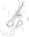
- FIG. 1illustrates an exemplary ultrasonic surgical instrument (10). At least part of instrument (10) may be constructed and operable in accordance with at least some of the teachings of U.S. Pat. No. 5,322,055 ; U.S. Pat. No. 5,873,873 ; U.S. Pat. No. 5,980,510 ; U.S. Pat. No. 6,325,811 ; U.S. Pat. No. 6,783,524 ; U.S. Pub. No. 2006/0079874 ; U.S. Pub. No. 2007/0191713 ; U.S. Pub. No. 2007/0282333 ; U.S. Pub. No. 2008/0200940 ; U.S. Pub. No.
- instrument (10)is operable to cut tissue and seal or weld tissue (e.g., a blood vessel, etc.) substantially simultaneously, using a combination of compression and ultrasonic vibrational energy.
- instrument (10)may have various structural and functional similarities with the HARMONIC ACE® Ultrasonic Shears, the HARMONIC WAVE® Ultrasonic Shears, the HARMONIC FOCUS® Ultrasonic Shears, and/or the HARMONIC SYNERGY® Ultrasonic Blades. Furthermore, instrument (10) may have various structural and functional similarities with the devices taught in any of the other references that are cited.
- Instrument (10) of the present examplecomprises a handpiece (20), a shaft assembly (30), and an end effector (40).
- Handpiece (20)comprises a body (22) including a finger grip (24) and a pair of buttons (26).
- Instrument (10)also includes a clamp arm assembly (50) that is pivotable toward and away from body (22).
- a proximal portion of clamp arm assembly (50)comprises a thumb grip (52).
- Thumb grip (52) and finger grip (24)together provide a scissor grip type of configuration. It should be understood, however, that various other suitable configurations may be used, including but not limited to a pistol grip configuration.
- a cap (33)is secured to a distal end of shaft assembly (30).
- End effector (40)includes an ultrasonic blade (42) extending distally from cap (33) of shaft assembly (30); and a pivoting clamp arm (54), which is an integral feature of clamp arm assembly (50).
- Clamp arm assembly (50)is pivotably coupled to a projection (34) extending laterally from shaft assembly (30) via a pivot member (36) (e.g., a pin, bearing, shaft, etc.) such that clamp arm (54) is pivotable toward and away from ultrasonic blade (42) to thereby clamp tissue between a clamp pad (55) of clamp arm (54) and ultrasonic blade (42).
- a pivot member (36)e.g., a pin, bearing, shaft, etc.
- clamp arm assembly (50)is pivotably coupled to projection (34) such that clamp arm assembly (50) pivots about an axis offset from a longitudinal axis (LAI). It should be understood that such rotation about an offset axis may allow for a narrower shaft assembly (30) profile. It should be understood that shaft assembly (30) passes through a portion of clamp arm assembly (50) such that as clamp arm assembly (50) rotates, clamp arm (54) rotates about a portion of shaft assembly (30). In particular, a first member (53A) and a second member (53B) of clamp arm assembly (50) are disposed about a distal portion of shaft assembly (30).
- Clamp arm assembly (50)is configured such that clamp arm (54) is pivotable toward ultrasonic blade (42) in response to pivoting of thumb grip (52) of clamp arm assembly (50) toward body (22); and such that clamp arm (54) is pivotable away from ultrasonic blade (42) in response to pivoting of thumb grip (52) of clamp arm assembly (50) away from body (22).
- a proximal end of clamp arm (54)is disposed within a distal recess (56) of a shank portion (51) of clamp arm assembly (50); and is secured therein by a pin (58).
- one or more resilient membersare used to bias clamp arm (54) and/or trigger (28) to the open position shown in FIG. 1 .
- a resilient membermay comprise a leaf spring, a torsion spring, and/or any other suitable kind of resilient member.
- an ultrasonic transducer assembly (12)extends proximally from body (22) of handpiece (20).
- Transducer assembly (12)is coupled with a generator (16) via a cable (14).
- Transducer assembly (12)receives electrical power from generator (16) and converts that power into ultrasonic vibrations through piezoelectric principles.
- Generator (16)may include a power source and control module that is configured to provide a power profile to transducer assembly (12) that is particularly suited for the generation of ultrasonic vibrations through transducer assembly (12).
- generator (16)may comprise a GEN 300 sold by Ethicon Endo-Surgery, Inc. of Cincinnati, Ohio.
- generator (16)may be constructed in accordance with at least some of the teachings of U.S. Pub. No. 2011/0087212 , entitled “Surgical Generator for Ultrasonic and Electrosurgical Devices,” published April 14, 2011. It should also be understood that at least some of the functionality of generator (16) may be integrated into handpiece (20), and that handpiece (20) may even include a battery or other on-board power source such that cable (14) is omitted. Still other suitable forms that generator (16) may take, as well as various features and operabilities that generator (16) may provide, will be apparent to those of ordinary skill in the art in view of the teachings herein.
- Ultrasonic vibrations that are generated by transducer assembly (12)are communicated along an acoustic waveguide (80), which extends through shaft assembly (30) to reach ultrasonic blade (42) as shown in FIG. 2 .
- Waveguide (80)is secured within shaft assembly (30) via a pin (32), which passes through waveguide (80) and shaft assembly (30).
- Pin (32)is located at a position along the length of waveguide (80) corresponding to a node associated with resonant ultrasonic vibrations communicated through waveguide (80).
- waveguide (80)may be configured to amplify mechanical vibrations transmitted through waveguide (80).
- waveguide (80)may include features operable to control the gain of the longitudinal vibrations along waveguide (80) and/or features to tune waveguide (80) to the resonant frequency of the system.
- the distal end of ultrasonic blade (42)is located at a position corresponding to an anti-node associated with resonant ultrasonic vibrations communicated through waveguide (80), in order to tune the acoustic assembly to a preferred resonant frequency f o when the acoustic assembly is not loaded by tissue.
- the distal end of ultrasonic blade (42)is configured to move longitudinally in the range of, for example, approximately 10 to 500 microns peak-to-peak, and in some instances in the range of about 20 to about 200 microns at a predetermined vibratory frequency f o of, for example, 55.5 kHz.
- transducer assembly (12) of the present exampleWhen transducer assembly (12) of the present example is activated, these mechanical oscillations are transmitted through the waveguide to reach ultrasonic blade (42), thereby providing oscillation of ultrasonic blade (42) at the resonant ultrasonic frequency.
- ultrasonic blade (42)when tissue is secured between ultrasonic blade (42) and clamp arm (54), the ultrasonic oscillation of ultrasonic blade (42) may simultaneously sever the tissue and denature the proteins in adjacent tissue cells, thereby providing a coagulative effect with relatively little thermal spread.
- an electrical currentmay also be provided through ultrasonic blade (42) and clamp arm (54) to also cauterize the tissue.
- buttons (26)may activate buttons (26) to selectively close switches (27) (see FIG. 2 ), thereby selectively activating transducer assembly (12) to activate ultrasonic blade (42).
- two buttons (26)are provided - one for activating ultrasonic blade (42) at a low power and another for activating ultrasonic blade (42) at a high power.
- a foot pedalmay be provided to selectively activate transducer assembly (12).
- Buttons (26) of the present exampleare positioned such that an operator may readily fully operate instrument (10) with a single hand.
- buttons (26)may be located at any other suitable positions.
- instrument (10)may be configured in numerous other ways as will be apparent to those of ordinary skill in the art in view of the teachings herein.
- at least part of instrument (10)may be constructed and/or operable in accordance with at least some of the teachings of any of the following: U.S. Pat. No. 5,322,055 ; U.S. Pat. No. 5,873,873 ; U.S. Pat. No. 5,980,510 ; U.S. Pat. No. 6,325,811 ; U.S. Pat. No. 6,783,524 ; U.S. Pub. No. 2006/0079874 ; U.S. Pub. No.
- an opening (33A)exists at a distal end of shaft assembly (30) between an exterior surface of ultrasonic blade (42) and an interior surface of cap (33). Opening (33A) provides access to an interior cavity of shaft assembly (30).
- the interior cavityis defined between an interior surface of shaft assembly (30) (including cap (33)) and exterior surfaces of waveguide (80) and ultrasonic blade (42). It may be desirable to provide features that seal this interior cavity such that surgical debris (e.g. tissue, coagulated blood, etc.), body fluid, etc. is prevented from entering. In particular, it may be desirable to provide a seal that extends between the exterior surface of waveguide (80) and/or ultrasonic blade (42) and the interior surface of cap (33).
- any radial seal discussed belowmay contact either or both of the exterior surfaces of waveguide (80) and/or ultrasonic blade (42).
- Radial seal (100)comprises a circular-resilient member having a semi-circular cross-sectional profile.
- the semi-circular cross-sectional profile of radial seal (100)presents a concave interior surface and a convex exterior surface.
- Radial seal (100)contacts the exterior surface of waveguide (80) along a pair of edges (100A, 100B) of radial seal (100).
- Radial seal (100)contacts the interior surface of cap (33) at an apex (100C) of the exterior convex surface of radial seal (100). It should be understood that these contact points extend completely circumferentially about the exterior surface of waveguide (80) and the interior surface of cap (33).
- Radial seal (100)defines a height (H1) between pair of edges (100A, 100B) and apex (100C).
- the interior cavity of shaft assembly (30)has a height (H2) represented by the distance between the exterior surface of waveguide (80) and the interior surface of cap (33).
- radial seal (100)flexes to assume height (H2) of the interior cavity of shaft assembly (30).
- Radial seal (100)may be configured such that height (H1) of radial seal (100) is greater than height (H2) of the interior cavity of shaft assembly (30).
- radial seal (100)may be resiliently biased to return to height (H1).
- radial seal (100)would cause radial seal (100) to apply force to the exterior surface of waveguide (80) via pair of edges (100A, 100B) and to the interior surface of cap (33) via apex (100C). It should further be understood that the resilient bias of radial seal (100) may be changed to apply more or less force to the exterior surface of waveguide (80) and/or the interior surface of cap (33). Radial seal (100) may be configured and positioned such that pair of edges (100A, 100B) contacts waveguide (80) at a node associated with resonant ultrasonic vibrations communicated through waveguide (80) and ultrasonic blade (42).
- radial seal (100)may be configured and positioned such that pair of edges (100A, 100B) contacts waveguide (80) away from a node associated with resonant ultrasonic vibrations communicated through waveguide (80) and ultrasonic blade (42).
- radial seal (100)may be configured to be longitudinally translatable such that pair of edges (100A, 100B) and/or apex (100C) of radial seal (100) may be used as a cleaning element to drive surgical debris, body fluid, etc. from the interior cavity of shaft assembly (30) (including cap (33)) and/or clean the exterior surface of waveguide (80), ultrasonic blade (42), and/or the interior surface of shaft assembly (30) (including cap (33)).
- radial seal (100) of the present examplecontacts the exterior surface of waveguide (80), it should be understood that radial seal (100) may alternatively contact the exterior surface of ultrasonic blade (42).
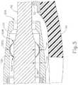
- FIG. 6shows an exemplary alternative radial seal (110) that is configured to extend between the exterior surface of waveguide (80) and the interior surface of cap (33) to thereby seal the interior cavity of shaft assembly (30).
- Radial seal (110)comprises a circular base (112) and a plurality of bristles (114).
- An exterior surface of circular base (112)is secured to the interior surface of cap (33).
- Bristles (114)are secured to an interior surface of base (112) and extend inwardly to the exterior surface of waveguide (80).
- radial seal (110)may be reconfigured such that the exterior surface of circular base (112) may be secured to the exterior surface of waveguide (80), with bristles (114) extending outwardly to the interior surface of cap (33).
- Bristles (114)may comprise nylon and/or another other appropriate material. A stiffness of each bristle (114) may be changed to thereby prevent more or less material from passing through. Also, bristles (114) may be arranged in a more or less dense configuration to thereby prevent more or less material from passing through.
- Radial seal (110)may be positioned such that bristles (114) contact waveguide (80) at a node associated with resonant ultrasonic vibrations communicated through waveguide (80) and ultrasonic blade (42). Alternatively, radial seal (110) may be positioned such that bristles (114) contacts waveguide (80) away from a node associated with resonant ultrasonic vibrations communicated through waveguide (80) and ultrasonic blade (42).
- radial seal (110)may be configured to be longitudinally translatable such that bristles (114) of radial seal (110) may be used as a cleaning element to drive surgical debris, body fluid, etc. from the interior cavity of shaft assembly (30) (including cap (33)) and/or clean the exterior surface of waveguide (80), ultrasonic blade (42), and/or the interior surface of shaft assembly (30) (including cap (33)).
- radial seal (110) of the present examplecontacts the exterior surface of waveguide (80), it should be understood that radial seal (110) may alternatively contact the exterior surface of ultrasonic blade (42).
- FIG. 7shows another exemplary alternative radial seal (120) that is configured to extend between the exterior surface of ultrasonic blade (42) and the interior surface of cap (33) to thereby seal the interior cavity of shaft assembly (30).
- Radial seal (120)comprises a circular member made of an absorbent material having a rectangular cross-sectional profile. Radial seal (120) is sized such that an exterior surface (122) of radial seal (120) contacts the interior surface of cap (33) and such that an interior surface (124) of radial seal (120) contacts the exterior surface of ultrasonic blade (42).
- the absorbent material of radial seal (120)may comprise felt and/or any other appropriate material.
- the absorbent material of radial seal (120)may be porous such that solid and/or semi-solid surgical debris may not pass through radial seal (120) whereas fluid may still pass through radial seal (120). A density of the absorbent material of radial seal (120) may be changed to thereby prevent more or less material from passing through. It should be understood that radial seal (120) may comprise a nonabsorbent/nonporous material to thereby prevent all surgical debris, body fluid, etc. from entering the interior cavity of shaft assembly (30).
- Radial seal (120)defines a height (H3) between interior surface (124) and exterior surface (122). As previously discussed, the interior cavity of shaft assembly (30) has a height (H2) represented by the distance between the exterior surface of ultrasonic blade (42) and the interior surface of cap (33). Radial seal (120) of the present example comprises a flexible material. When placed within opening (33A), radial seal (120) flexes to assume height (H2) of the interior cavity of shaft assembly (30). Radial seal (120) may be configured such that height (H3) of radial seal (120) is greater than height (H2) of the interior cavity of shaft assembly (30). Furthermore, the flexible material of radial seal (120) may cause radial seal (120) to be resiliently biased to return to height (H3).
- radial seal (120)may be changed by changing the flexible material to apply more or less force to the exterior surface of ultrasonic blade (42) and/or the interior surface of cap (33).
- Radial seal (120)may be positioned such that interior surface (124) contacts ultrasonic blade (42) at a node associated with resonant ultrasonic vibrations communicated through waveguide (80) and ultrasonic blade (42).
- radial seal (120)may be positioned such that interior surface (124) contacts ultrasonic blade (42) away from a node associated with resonant ultrasonic vibrations communicated through waveguide (80) and ultrasonic blade (42).
- radial seal (120)may be configured to be longitudinally translatable such that exterior surface (122) and/or interior surface (124) of radial seal (120) may be used as a cleaning element to drive surgical debris, body fluid, etc. from the interior cavity of shaft assembly (30) (including cap (33)) and/or clean the exterior surface of waveguide (80), ultrasonic blade (42), and/or the interior surface of shaft assembly (30) (including cap (33)).
- radial seal (120) of the present examplecontacts the exterior surface of ultrasonic blade (42), it should be understood that radial seal (120) may alternatively contact the exterior surface of waveguide (80).
- FIG. 8shows another exemplary alternative radial seal (130) that is configured to extend between the exterior surface of ultrasonic blade (42) and the interior surface of cap (33) to thereby seal the interior cavity of shaft assembly (30).
- Radial seal (130)comprises a circular member made of a flexible material having a circular cross-sectional profile (e.g. similar to an o-ring).
- Radial seal (130)is sized such that an exterior surface (132) of radial seal (130) contacts the interior surface of cap (33) and such that an interior surface (134) of radial seal (130) contacts the exterior surface of ultrasonic blade (42).
- Radial seal (130)defines a height (H4) between an inner most point of interior surface (130) and an outer most point of exterior surface (132).
- the interior cavity of shaft assembly (30)has a height (H2) represented by the distance between the exterior surface of ultrasonic blade (42) and the interior surface of cap (33).
- H2height
- radial seal (130)flexes to assume height (H2) of the interior cavity of shaft assembly (30).
- Radial seal (130)may be configured such that height (H4) of radial seal (130) is greater than height (H2) of the interior cavity of shaft assembly (30).
- the flexible material of radial seal (130)may cause radial seal (130) to be resiliently biased to return to height (H4).
- radial seal (130)may be changed by changing the flexible material to apply more or less force to the exterior surface of ultrasonic blade (42) and/or the interior surface of cap (33).
- Radial seal (130)may be positioned such that interior surface (134) contacts ultrasonic blade (42) at a node associated with resonant ultrasonic vibrations communicated through waveguide (80) and ultrasonic blade (42).
- radial seal (130)may be positioned such that interior surface (134) contacts ultrasonic blade (42) away from a node associated with resonant ultrasonic vibrations communicated through waveguide (80) and ultrasonic blade (42).
- radial seal (130)may be configured to be longitudinally translatable such that exterior surface (132) and/or interior surface (134) of radial seal (130) may be used as a cleaning element to drive surgical debris, body fluid, etc. from the interior cavity of shaft assembly (30) (including cap (33)) and/or clean the exterior surface of waveguide (80), ultrasonic blade (42), and/or the interior surface of shaft assembly (30) (including cap (33)).
- radial seal (130) of the present examplecontacts the exterior surface of ultrasonic blade (42), it should be understood that radial seal (130) may alternatively contact the exterior surface of waveguide (80).
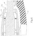
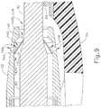
- FIG. 9shows another exemplary alternative radial seal (140) that is configured to extend between the exterior surface of ultrasonic blade (42) and the interior surface of cap (33) to thereby seal the interior cavity of shaft assembly (30).
- Radial seal (140)comprises a conical member (142).
- a first end (142A) of conical member (142)comprises a first radial circumference.
- a second end (142B) of conical member (142)comprises a second radial circumference.
- the first radial circumference of first end (142A)is greater than the second radial circumference of second end (142B).
- Conical member (142)is oriented within the interior cavity of shaft assembly (30) such that first end (142A) of conical member (142) is proximal of second end (142B) of conical member (142).
- a lip (144)projects from an exterior surface of first end (142A) of conical member (142).
- Conical member (142)is sized such that lip (144) of conical member (142) contacts the interior surface of cap (33) and such that an edge (146) of second end (142B) of conical member (142) contacts the exterior surface of ultrasonic blade (42).
- Conical member (142)may be biased to apply force upon to the exterior surface of ultrasonic blade (42) via edge (146) and to the interior surface of cap (33) via lip (144), such that conical member (142) substantially seals the region of the interior cavity of shaft assembly (30) proximal of conical member (142).
- Cap (33) of the present examplecomprises a plurality of openings (148). Openings (148) pass completely through cap (33). Openings (148) may comprise discrete circular openings and/or slots that extend along the circumference of cap (33) to any suitable extent. Openings (148) are formed in cap (33) distally of lip (144) such that the interior cavity of shaft assembly (30) remains sealed. As surgical debris, body fluid, etc. enters the interior cavity of shaft assembly (30) via opening (33A), the exterior surface of conical member (142) guides surgical debris, body fluid, etc. toward openings (148). Openings (148) allow for fluid to pass through into a distal portion of the interior cavity of cap (33) to thereby drive surgical debris, body fluid, etc. from the interior cavity of cap (33).
- Conical member (142)may be positioned such that edge (146) contacts ultrasonic blade (42) at a node associated with resonant ultrasonic vibrations communicated through waveguide (80) and ultrasonic blade (42).
- conical member (142)may be positioned such that edge (146) contacts ultrasonic blade (42) away from a node associated with resonant ultrasonic vibrations communicated through waveguide (80) and ultrasonic blade (42).
- radial seal (140)may be configured to be longitudinally translatable such that lip (144) and/or edge (146) of conical member (142) may be used as a cleaning element to drive surgical debris, body fluid, etc. from the interior cavity of shaft assembly (30) (including cap (33)) and/or clean the exterior surface of waveguide (80), ultrasonic blade (42), and/or the interior surface of shaft assembly (30) (including cap (33)).
- conical member (142) of the present examplecontacts the exterior surface of ultrasonic blade (42), it should be understood that conical member (142) may alternatively contact the exterior surface of waveguide (80).
- FIG. 10shows another exemplary alternative radial seal (150) that is configured to extend between the exterior surfaces of waveguide (80) and ultrasonic blade (42) and the interior surface of cap (33) to thereby seal the interior cavity of shaft assembly (30).
- Radial seal (150)comprises a soft material disposed within the interior cavity of shaft assembly (30).
- the soft material of radial seal (140)may be configured to not interrupt or significantly dampen the ultrasonic vibrations communicated through waveguide (80).
- the soft material of radial seal (150)prevents surgical debris, body fluid, etc. from passing into the interior cavity of shaft assembly (30) and from contacting waveguide (80) and ultrasonic blade (42) along the portions of waveguide (80) and ultrasonic blade (42) covered by the soft material of radial seal (150).
- the soft material of radial seal (150)may comprise liquid repellant material to discourage accumulation of liquid within the interior cavity of shaft assembly (30).
- the soft material of radial seal (150)may be porous such that solid and/or semi-solid surgical debris may not pass through radial seal (150) whereas fluid may still pass through radial seal (150).
- a density of the soft material of radial seal (150)may be changed to thereby prevent more or less material from passing through.
- Radial seal (150)may be removed from the interior cavity of shaft assembly (30) after use such that surgical debris, body fluid, etc. caught within the soft material of radial seal (150) may be removed from the interior cavity of shaft assembly (30).
- radial seal (150)may be used as a cleaning element to remove surgical debris, body fluid, etc. from the interior cavity of shaft assembly (30) (including cap (33)) and/or clean the exterior surface of waveguide (80), ultrasonic blade (42), and/or the interior surface of shaft assembly (30) (including cap (33)).
- opening (33A)provides access to an interior cavity of shaft assembly (30).
- Various examples of features that may be used to clean surgical debris, body fluid, etc. from the interior cavity of shaft assembly (30)will be described in greater detail below, while other examples will be apparent to those of ordinary skill in the art in view of the teachings herein.
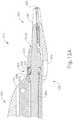
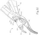
- FIGS. 11-12Dshow one merely illustrative example of an instrument (210) with a cavity cleaning element (200).
- Instrument (210) of the present exampleis configured to operate substantially similar to instrument (10) discussed above except for the differences discussed below.
- instrument (210) of the present examplecomprises a handpiece (220), a shaft assembly (230), and an end effector (240).
- Handpiece (220)comprises a body (222).
- Instrument (210)also includes a clamp arm assembly (250) that is pivotable toward and away from body (222).
- a cap (233)is secured to a distal end of shaft assembly (230).
- End effector (240)includes an ultrasonic blade (242) extending distally from cap (233) of shaft assembly (230); and a pivoting clamp arm (254), which is an integral feature of clamp arm assembly (250).
- Clamp arm assembly (250)is pivotably coupled to a projection (234) extending laterally from shaft assembly (230) such that clamp arm (254) is pivotable toward and away from ultrasonic blade (242) to thereby clamp tissue between a clamp pad (255) of clamp arm (254) and ultrasonic blade (242).
- Ultrasonic vibrations that are generated by a transducer assemblyare communicated along an acoustic waveguide (280), which extends through shaft assembly (230) to reach ultrasonic blade (242).
- Ultrasonic blade (242)vibrates at ultrasonic frequencies to cut and/or seal tissue.
- cleaning element (200)comprises a circular member having a triangular cross-sectional profile.
- An interior surface (202) of cleaning element (200)contacts an exterior surface of waveguide (280).
- a proximal surface (204) of cleaning element (200)extends perpendicularly from a proximal end of interior surface (202) to an interior surface of cap (233).
- a distal surface (206) of cleaning element (200)extends angularly from a proximal end of interior surface (202) to the interior surface of cap (233).
- Proximal surface (204) and distal surface (206)come together and form an edge (208) that contacts the interior surface of cap (233).
- cleaning element (200)need not be limited to a circular shape. Any other suitable shapes/configurations may be used.
- instrument (210)comprises a sliding trigger (244).
- Sliding trigger (244)is longitudinally translatable between a proximal position and a distal position within a longitudinal slot (246) formed in body (222).
- Cleaning element (200)is mechanically connected with sliding trigger (244) such that longitudinal translation of sliding trigger (244) causes concurrent longitudinal translation of cleaning element (200).
- interior surface (202) and edge (208) of cleaning element (200)act as wipers to clean the exterior surface of waveguide (280) and/or the interior surface of cap (233).
- longitudinal translation of cleaning element (200)drives surgical debris, body fluid, etc. from an interior cavity of shaft assembly (230).
- sliding trigger (244)may be coupled within cleaning element (200) will be apparent to those of ordinary skill in the art in view of the teachings herein.
- FIG. 12Ashows cleaning element (200) in a proximal position.
- surgical debrise.g. tissue, coagulated blood, etc.
- body fluid (2)may enter into the interior cavity of shaft assembly (230) via an opening (233A) at a distal end of cap (233) as shown in FIG. 12B .
- the usermay translate cleaning element (200) longitudinally distally by translating sliding trigger (244) longitudinally distally.
- sliding trigger244
- cleaning element (200)longitudinal distal translation of cleaning element (200) to a distal position drives surgical debris and/or body fluid (2) distally from the interior cavity of shaft assembly (230), out through opening (233A), and thereby cleans the interior surface of cap (233) and/or the exterior surface of waveguide (280).
- cleaning element (200)may be moved back to the proximal position as shown in FIG. 12D by translating sliding trigger (244) longitudinally proximally.
- Instrument (210)may be configured such that cleaning element (200) contacts waveguide (280) at a node associated with resonant ultrasonic vibrations communicated through waveguide (280) and ultrasonic blade (242) when cleaning element (200) is in the proximal position.
- instrument (210)may be configured such that cleaning element (200) contacts waveguide (280) away from a node associated with resonant ultrasonic vibrations communicated through waveguide (280) and ultrasonic blade (242) when cleaning element (200) is in the proximal position.
- cleaning element (200) of the present examplecontacts the exterior surface of waveguide (280), it should be understood that cleaning element (200) may alternatively contact the exterior surface of ultrasonic blade (242).
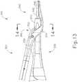
- FIGS. 13-15Bshow an exemplary alternative instrument (310) with a cleaning element (300) configured to clean and/or drive surgical debris, body fluid, etc. from the interior cavity of a shaft assembly (330).
- Instrument (310) of the present exampleis configured to operate substantially similar to instruments (10, 210) discussed above except for the differences discussed below.
- instrument (310) of the present examplecomprises a shaft assembly (330) and an end effector (340).
- Instrument (310)also includes a clamp arm assembly (350) that is pivotable toward and away from shaft assembly (330).
- a cap (333)is secured to a distal end of shaft assembly (330).
- End effector (340)includes an ultrasonic blade (342) extending distally from cap (333) of shaft assembly (330); and a pivoting clamp arm (354), which is an integral feature of clamp arm assembly (350).
- Clamp arm assembly (350)is pivotably coupled to a projection (334) extending laterally from shaft assembly (330) such that clamp arm (354) is pivotable toward and away from ultrasonic blade (342) to thereby clamp tissue between a clamp pad (355) of clamp arm (354) and ultrasonic blade (342).
- Ultrasonic vibrations that are generated by a transducer assembly (not shown)are communicated along an acoustic waveguide (380), which extends through shaft assembly (330) to reach ultrasonic blade (342).
- Ultrasonic blade (342)vibrates at ultrasonic frequencies to cut and/or seal tissue.
- cleaning element (300)comprises a body (302) pivotably coupled to clamp arm (354).
- Body (302)comprises a first yoke portion (302A), a curved neck (302B), and a second yoke portion (302C).
- First yoke portion (302A)is pivotably coupled with clamp arm (354).
- Curved neck (302B)extends proximally and downwardly from first yoke portion (302A).
- Curved neck (302B)passes through a longitudinal slot (333B) formed in a top surface of cap (333).
- Second yoke portion (302C)extends downwardly from a portion of curved neck (302B) disposed within an interior cavity of shaft assembly (330).
- Second yoke portion (302C)is shaped to complement an exterior surface of waveguide (380) and the interior surface of cap (333).
- second yoke portion (302C)is a C-shape and is disposed about waveguide (380).
- second yoke portion (302C)is slidably coupled about waveguide (380).
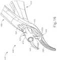
- FIG. 15Ashows cleaning element (300) in a proximal position.
- Cleaning element (300) in the proximal positioncorresponds to clamp arm (354) being pivoted toward ultrasonic blade (342) such that clamp pad (355) of clamp arm (354) contacts ultrasonic blade (342).
- With cleaning element (300) in the proximal positionsurgical debris, body fluid, etc. may enter into the interior cavity of shaft assembly (330) via an opening (333A) at a distal end of cap (333).
- cleaning element (300)may be moved back to the proximal position as shown in FIG. 12A by rotating clamp arm (354) toward ultrasonic blade (342).
- rotating clamp arm (354)toward ultrasonic blade (342).
- second yoke portion (302C)may comprise an elastomeric wiper that extends inwardly from an interior surface of second yoke portion (302C) and contacts the exterior surface of waveguide (380). It should further be understood that in some versions of instrument (310), second yoke portion (302C) may comprise an elastomeric wiper that extends outwardly from an exterior surface of second yoke portion (302C) and contacts the interior surface of cap (333).
- Instrument (310)may be configured such that second yoke portion (302C) of body (302) of cleaning element (300) contacts waveguide (380) at a node associated with resonant ultrasonic vibrations communicated through waveguide (380) and ultrasonic blade (342) when cleaning element (300) is in the proximal position.
- instrument (310)may be configured such that second yoke portion (302C) of body (302) of cleaning element (300) contacts waveguide (380) away from a node associated with resonant ultrasonic vibrations communicated through waveguide (380) and ultrasonic blade (342) when cleaning element (300) is in the proximal position.
- second yoke portion (302C) of cleaning element (300) of the present examplecontacts the exterior surface of waveguide (380), it should be understood that second yoke portion (302C) of cleaning element (300) may alternatively contact the exterior surface of ultrasonic blade (342).
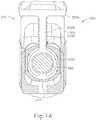
- FIGS. 16-17Cshow another exemplary alternative instrument (410) with a cleaning element (400) configured to clean and/or drive surgical debris, body fluid, etc. from the interior cavity of a shaft assembly (430).
- Instrument (410) of the present exampleis configured to operate substantially similar to instruments (10, 210, 310) discussed above except for the differences discussed below.
- instrument (410) of the present examplecomprises a shaft assembly (430) and an end effector (440).
- Instrument (410)also includes a clamp arm assembly (450) that is pivotable toward and away from shaft assembly (430).
- a cap (433)is secured to a distal end of shaft assembly (430).
- End effector (440)includes an ultrasonic blade (442) extending distally from cap (433) of shaft assembly (430); and a pivoting clamp arm (454), which is an integral feature of clamp arm assembly (450).
- Clamp arm assembly (450)is pivotably coupled to a projection (434) extending laterally from shaft assembly (430) such that clamp arm (454) is pivotable toward and away from ultrasonic blade (442) to thereby clamp tissue between a clamp pad (455) of clamp arm (454) and ultrasonic blade (442).
- Ultrasonic vibrations that are generated by a transducer assembly (not shown)are communicated along an acoustic waveguide (480), which extends through shaft assembly (430) to reach ultrasonic blade (442).
- Ultrasonic blade (442)vibrates at ultrasonic frequencies to cut and/or seal tissue.
- cleaning element (400)comprises a pair of flexible members (402A, 402B) projecting from a top surface of clamp arm (454).
- Flexible members (402A, 402B)are angled inwardly.
- Cap (433) of the present exampleincludes a pair of slots (435) formed in a bottom surface of cap (433) and a pair of slots (437) formed in a top surface of cap (433).
- flexible members (402A, 402B)pass through slots (435) formed in cap (433), flexible members (402A, 402B) engage an exterior surface of waveguide (480).
- Slots (437)are angled outwardly such that as flexible members (402, 402B) pass through slots (437), flexible members (402A, 402B) will be driven outwardly and away from the exterior surface of waveguide (480).
- the movement of flexible members (402A, 402B) across the exterior surface of waveguide (480)cleans surgical debris, body fluid, etc. from the exterior surface of waveguide (480) and the interior of shaft assembly (430).
- FIG. 16shows clamp arm (454) in an open position.
- flexible members (402A, 402B)are completely removed from the interior cavity of shaft assembly (430).
- FIG. 17Ashows clamp arm (454) in a partially open position. In this partially open position, flexible members (402A, 402B) are partially disposed within the interior cavity of shaft assembly (430) via slots (435) formed in the bottom surface of cap (433). In this partially open position, flexible members (402A, 402B) have not yet engaged the exterior surface of waveguide (480). As shown in FIG.
- flexible members (402A, 402B)will move across the exterior surface of waveguide (480) as clamp arm (454) is moved toward and away from ultrasonic blade (442). This movement of flexible members (402A, 402B) across the exterior surface of waveguide (480) cleans the exterior surface of waveguide (480) and the interior of shaft assembly (430) of surgical debris, body fluid, etc.
- Flexible members (402A, 402B)may be configured and/or positioned such that flexible members (402A, 402B) contact waveguide (480) at a node associated with resonant ultrasonic vibrations communicated through waveguide (480) and ultrasonic blade (442).
- flexible members (402A, 402B)may be configured and/or positioned such that flexible members (402A, 402B) contact waveguide (480) away from a node associated with resonant ultrasonic vibrations communicated through waveguide (480) and ultrasonic blade (442).
- instrument (410) of the present exampleis configured such that flexible members (402A, 402B) contact the exterior surface of waveguide (480), it should be understood that instrument (410) may alternatively be configured such that flexible members (402A, 402B) contact the exterior surface of ultrasonic blade (442).
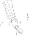
- FIGS. 18 and 19show an exemplary alternative shaft assembly (530) with an exemplary cap (533) configured to allow surgical debris, body fluid, etc. to be driven from the interior cavity of a shaft assembly (530).
- Cap (533)is secured to a distal end of shaft assembly (530).
- An ultrasonic blade (542)extends distally from cap (533) of shaft assembly (530). Ultrasonic vibrations that are generated by a transducer assembly (not shown) are communicated along an acoustic waveguide (580), which extends through shaft assembly (530) to reach ultrasonic blade (542). Ultrasonic blade (542) vibrates at ultrasonic frequencies to cut and/or seal tissue.
- shaft assembly (530) of the present examplemay be used with any instrument (10, 210, 310, 410) discussed above.
- cap (533)may comprise any of the features of caps (33, 233, 333, 433) discussed above.
- Cap (533) of the present exampleincludes a plurality of openings (533B). Openings (533B) pass completely through cap (533). Openings (533B) are formed in a proximal portion of cap (533). Openings (533B) allow for fluid to pass out of interior cavity of shaft assembly (530) to thereby drive any surgical debris and/or body fluid (2) from the interior cavity of shaft assembly (530). For instance, as shown in FIG. 19 , a distal portion of shaft assembly (530) may be dipped into a cup of saline (4) or any other appropriate cleaning liquid.
- openings (533B)allow air to escape from the interior cavity of shaft assembly (530) as the saline enters the interior cavity of shaft assembly (530) through an opening (533A) formed in the distal end of cap (533).
- This saline within the interior cavity of shaft assembly (530)may loosen surgical debris and/or body fluid (2) within the interior cavity of shaft assembly (530).
- Vibration of ultrasonic blade (542)e.g., while the distal portion of shaft assembly (530) is still dipped in saline) may improve the ability of the saline to loosen surgical debris and/or body fluid (2).
- shaft assembly (530)As the distal portion of shaft assembly (530) is removed from the saline, it should be understood that saline will pass out of the interior cavity of shaft assembly (530) via opening (533A) to thereby remove loosened surgical debris and/or body fluid (2) from the interior cavity of shaft assembly (530). As the saline passes out of the interior cavity of shaft assembly (530), it should be understood that openings (533B) will allow air to enter into the interior cavity of shaft assembly (530) such that openings (533B) promote drainage through opening (533A).
- activation of ultrasonic blade (542) in the salinemay draw the saline into the interior cavity of shaft assembly (530) via opening (533A), such that the loosened surgical debris and/or body fluid (2) exits the interior cavity of shaft assembly (530) via openings (533B).
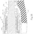
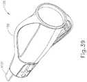
- FIGS. 20 and 21show an alternative cap (633) according to the present invention configured to clean and/or drive surgical debris, body fluid, etc. from the interior cavity of a shaft assembly (630).
- Cap (633)is rotatably coupled to a distal end of shaft assembly (630) such that cap (633) is rotatable about a longitudinal axis defined by shaft assembly (630).
- An ultrasonic blade (642)extends distally from cap (633) of shaft assembly (630). Ultrasonic vibrations that are generated by a transducer assembly (not shown) are communicated along an acoustic waveguide (680), which extends through shaft assembly (630) to reach ultrasonic blade (642). Ultrasonic blade (642) vibrates at ultrasonic frequencies to cut and/or seal tissue.
- shaft assembly (630) of the present embodimentmay be used with any instrument (10, 210, 310, 410, 510) discussed above.
- cap (633)may comprise any of the features of caps (33, 233, 333, 433, 533) discussed above.
- Cap (633)comprises a plurality of helical projections (633A) extending inwardly from an interior surface of cap (633). As shown in FIG. 21 , helical projections (633A) extend from the interior surface of cap (633) and contact an exterior surface of waveguide (680). In some versions of cap (633), helical projections (633A) may comprise an elastomeric wiper that extends inwardly from an interior surface of each helical projection (633A) and contacts the exterior surface of waveguide (680). A plurality of openings (633B) exist between helical projections (633A) such that surgical debris, body fluid, etc. may pass through.
- cap (633)is rotatably coupled with the distal end of shaft assembly (630), cap (633) may be manually rotated by a user. Rotation of cap (633) causes rotation of helical projections (633A) to thereby drive surgical debris, body fluid, etc. from the interior cavity of shaft assembly (630) and clean the exterior surface of ultrasonic blade (642). It should be understood that cap (633) may include features that permit cap (633) to only rotate in a single direction (e.g. such that helical projections (633A) can only drive surgical debris, body fluid, etc. distally). It should also be understood that cap (633) may include any suitable number of helical projections (633A). By way of example only, some versions of cap (633) may have just one helical projection (633A). Other versions of cap (633) may have two or more helical projections (633A).
- cap (633)may be configured such that movement of a clamp arm toward and/or away from ultrasonic blade (642) causes rotation of cap (633) thereby driving surgical debris, body fluid, etc. from the interior cavity of shaft assembly (630) and cleaning the exterior surface of ultrasonic blade (642) each time the clamp arm is moved.
- Helical projections (633A)may be configured and/or positioned such that helical projections (633A) contact waveguide (680) at nodes associated with resonant ultrasonic vibrations communicated through waveguide (680) and ultrasonic blade (642).
- helical projections (633A)may be configured and/or positioned such that helical projections (633A) contact waveguide (680) away from nodes associated with resonant ultrasonic vibrations communicated through waveguide (680) and ultrasonic blade (642).
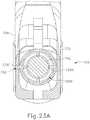
- FIGS. 22-23Bshow an alternative cap (733) according to the present invention configured to clean and/or drive surgical debris, body fluid, etc. from the interior cavity of a shaft assembly (730).
- Cap (733)is rotatably coupled to a distal end of shaft assembly (730) such that cap (733) is rotatable about a longitudinal axis defined by shaft assembly (730).
- An ultrasonic blade (742)extends distally from cap (733) of shaft assembly (730). Ultrasonic vibrations that are generated by a transducer assembly (not shown) are communicated along an acoustic waveguide (780), which extends through shaft assembly (730) to reach ultrasonic blade (742). Ultrasonic blade (742) vibrates at ultrasonic frequencies to cut and/or seal tissue.
- shaft assembly (730) of the present embodimentmay be used with any instrument (10, 210, 310, 410, 510) discussed above.
- cap (733)may comprise any of the features of caps (33, 233, 333, 433, 533,633) discussed above.
- Cap (733)comprises a plurality of longitudinal projections (733A) extending inwardly from an interior surface of cap (733). As shown in FIGS. 23A-23B , longitudinal projections (733A) extend from the interior surface of cap (733) and contact an exterior surface of waveguide (780). In some versions of cap (733), longitudinal projections (733A) may comprise an elastomeric wiper that extends inwardly from an interior surface of each longitudinal projection (733A) and contacts the exterior surface of waveguide (780). A plurality of longitudinal openings (733B) exist between longitudinal projections (733A) such that surgical debris, body fluid, etc. may pass through. Because cap (733) is rotatably coupled with the distal end of shaft assembly (730), cap (733) may be rotated.
- cap (733)causes rotation of longitudinal projections (733A) to thereby clean the exterior surface of waveguide (780). While longitudinal projections (733A) are oriented longitudinally in the present embodiment, it should be understood that longitudinal projections (733A) may alternatively be oriented obliquely, helically, or otherwise oriented. It should also be understood that cap (733) may include any suitable number of longitudinal projections (733A). By way of example only, some versions of cap (733) may have just one longitudinal projection (733A). Other versions of cap (733) may have two or more longitudinal projections (733A).
- cap (733)comprises a tab (733C) projecting outwardly from an exterior surface of cap (733).
- a clamp arm (754) of the present embodimentcomprises an opening (755).
- Cap (733)is oriented such that tab (733C) is positioned within opening (755) of clamp arm (754).
- FIG. 23Ashows clamp arm (754) in a closed position. With clamp arm (754) in the closed position, cap (733) and longitudinal projections (733A) are in a first rotational position.
- FIG. 23Bshows clamp arm (754) moved away from ultrasonic blade (742) in a partially open position. Movement of clamp arm (754) away from ultrasonic blade (742) causes movement of opening (755).
- opening (755)drives concurrent movement of tab (733C) of cap (733) and thereby rotates cap (733) and longitudinal projections (733A) in a first direction.
- movement of clamp arm (754) toward ultrasonic blade (742)would cause rotation of cap (733) and longitudinal projections (733A) in a second direction.
- Rotation of longitudinal projections (733A)cleans the exterior surface of waveguide (780) of surgical debris, body fluid, etc.
- opening and closing of clamp arm (754)would clean the exterior surface of waveguide (780) by partially rotating cap (733) about waveguide (780) in an oscillatory fashion.
- cap (733)may include features that permit cap (733) to only rotate in a single direction.
- cap (733)may further include a ratchet and pawl feature that drives cap (733) to rotate incrementally each time clamp arm (754) is moved away from ultrasonic blade (742); and does not drive cap (733) to rotate as clamp arm (754) is moved toward ultrasonic blade (742) or vice versa.
- opening (33A) of cap (33) of instrument (10)provides access to an interior cavity of shaft assembly (30) of instrument (10). It may be desirable to provide protective elements that prevent surgical debris, body fluid, etc. from contacting at least part of the exterior surface of waveguide (80) and/or ultrasonic blade (42) within the interior cavity of shaft assembly (30). Such protective elements need not necessarily seal off the interior cavity. Various merely illustrative examples of such protective elements will be described in greater detail below, while other examples will be apparent to those of ordinary skill in the art in view of the teachings herein.
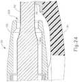
- FIG. 24shows one merely illustrative example of a protective element (800).
- Protective element (800) of this examplecomprises a protective coating on a distal portion of ultrasonic blade (42).
- the protective coatingmay comprise a non-stick coating, including but not limited to polytetrafluoroethylene ("PTFE"), to thereby prevent surgical debris, body fluid, etc. within the interior cavity of shaft assembly (30) from sticking to waveguide (80) and/or ultrasonic blade (42).
- the protective coatingmay provide insulation of waveguide (80) and/or ultrasonic blade (42) such that heat is not transferred from waveguide (80) and/or ultrasonic blade (42) to thereby prevent coagulation of surgical debris, body fluid, etc. within the interior cavity of shaft assembly (30).
- the protective coatingmay be a lubricous and/or hydrophobic coating (e.g. sodium stearate, etc.) to thereby prevent surgical debris, body fluid, etc. within the interior cavity of shaft assembly (30) from becoming dry.
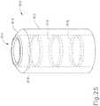
- FIGS. 25 and 26show an exemplary alternative protective element (810) configured to prevent surgical debris, body fluid, etc. from contacting the exterior surface of waveguide (80) within the interior cavity of shaft assembly (30).
- Protective element (810)comprises a cylindrical body (812) having a tapered end (814).
- a circular bore (816)passes completely through cylindrical body (812) and tapered end (814) of protective element (810).
- a plurality of circular projections (818)extend inwardly from an interior surface of circular bore (816). As best seen in FIG. 26 , circular projections (818) have a triangular cross-sectional profile. Each circular projection (818) presents an edge (818A).
- Protective element (810)is disposed within the interior cavity of shaft assembly (30) such that waveguide (80) passes through bore (816) of protective element (810). With waveguide (80) positioned within bore (816), each edge (818A) of each circular projection (818) contacts waveguide (80) thereby preventing cylindrical body (812) and tapered end (814) from contacting waveguide (80). It should be understood that the contact point between edge (818A) of each circular projections (818) and the exterior surface of waveguide (80) extends completely circumferentially about the exterior surface of waveguide (80). This contact may provide a radial seal that prevents contact of solid and/or semi-solid surgical debris from contacting waveguide (80).
- protective element (810)may comprise an absorbent material configured to absorb fluid and prevent it from contacting waveguide (80).
- circular projections (818)may act as wicks, drawing fluid away from waveguide (80) and toward cylindrical body (812), where it is absorbed and retained.
- protective element (810)may comprise a soft material configured to not interrupt or significantly dampen the ultrasonic vibrations communicated through waveguide (80).
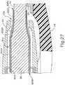
- FIG. 27shows another exemplary alternative protective element (820) configured to prevent surgical debris, body fluid, etc. from contacting the exterior surface of waveguide (80) and ultrasonic blade (42) within the interior cavity of shaft assembly (30).
- Protective element (820)comprises a flexible sleeve having a first cylindrical section (822A), a tapered section (822B), and a second cylindrical section (822C).
- First cylindrical section (822A), second cylindrical section (822C), and tapered section (822B)are flexible and sized to fit about a distal portion of waveguide (80), a proximal portion of ultrasonic blade (42), and a transitional portion between waveguide (80) and ultrasonic blade (42) respectively.
- first cylindrical section (822A), tapered section (822B), and second cylindrical section (822C)are sized such that when disposed about ultrasonic blade (42) a small gap exists between the exterior surface of ultrasonic blade (42) and an interior surface of protective element (820). This small gap prevents surgical debris, body fluid, etc. that is larger than the small gap from contacting ultrasonic blade (42). It should be understood that the size and/or flexibly of protective element (820) may be changed to thereby change the size of the small gap existing between protective element (820) and ultrasonic blade (42).
- a plurality of flexible scrubbing features (824)extend from the interior surface of protective element (820) and contact the exterior surface of waveguide (80) and ultrasonic blade (42). As waveguide (80) and ultrasonic blade (42) vibrate, scrubbing features (824) scrub surgical debris, body fluid, etc. from the exterior surface of waveguide (80) and ultrasonic blade (42). Openings (826A, 826B) at each end of protective element (820) allow for scrubbed surgical debris, body fluid, etc. to pass through the small gap between protective element (820) and ultrasonic blade (42).
- FIG. 28shows yet another exemplary alternative protective element (830) configured to prevent surgical debris, body fluid, etc. from contacting the exterior surface of waveguide (80) and ultrasonic blade (42) within the interior cavity of shaft assembly (30).
- Protective element (830)comprises a flexible sleeve having a first cylindrical section (832A), a tapered section (832B), and a second cylindrical section (832C).
- First cylindrical section (832A), second cylindrical section (832C), and tapered section (832B)are flexible and sized to fit about a distal portion of waveguide (80), a proximal portion of ultrasonic blade (42), and a transitional portion between waveguide (80) and ultrasonic blade (42) respectively.
- first cylindrical section (832A), tapered section (832B), and second cylindrical section (832C)are sized such that when disposed about ultrasonic blade (42) a small gap exists between the exterior surface of ultrasonic blade (42) and an interior surface of protective element (830). This small gap prevents surgical debris, body fluid, etc. that is larger than the small gap from contacting ultrasonic blade (42). It should be understood that the size and/or flexibly of protective element (830) may be changed to thereby change the size of the small gap existing between protective element (830) and ultrasonic blade (42).
- Protective element (830)comprises a plurality of openings (834). Each opening of plurality of openings (834) present an edge (834A) on an interior surface of protective element (830). As waveguide (80) and ultrasonic blade (42) vibrate, edges (834A) scrape surgical debris, body fluid, etc. from the exterior surface of waveguide (80) and ultrasonic blade (42). Openings (836A, 836B) at each end of protective element (830) allow for scraped surgical debris, body fluid, etc. to pass through the small gap between protective element (830) and ultrasonic blade (42).
- cap (33) of instrument (10)provides access to an interior cavity of shaft assembly (30) of instrument (10). It may be desirable to provide cap (33) with features that allow for the interior cavity of shaft assembly (30) to be efficiently cleaned.
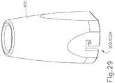
- An example of such a cap (900)is shown in FIGS. 29-30B .
- Cap (900) of the present examplecomprises a bayonet feature (902).
- Bayonet feature (902)comprises an L-shaped slot (902A).
- a distal end of an exemplary shaft assembly (904)comprises a mating bayonet feature (906).
- Bayonet feature (906)comprises a pin (906A) projecting from an exterior surface of the distal end of shaft assembly (904).
- L-shaped slot (902A) of bayonet feature (902)is configured to selectively receive the pin (906A) of bayonet feature (906) to selectively lock cap (900) to the distal end of shaft assembly (904).
- Bayonet features (902, 906)allow for a user to quickly remove cap (900) from the distal end of shaft assembly (904) such that the interior cavity of shaft assembly (30), waveguide (80), and/or ultrasonic blade (42) may be cleaned.
- bayonet features (902, 906)allow for a user to quickly reattach cap (900) to the distal end of shaft assembly (30). It should be understood that cap (900) may comprise any of the features of caps (33, 233, 333, 433, 533,633, 733) discussed above.
- FIGS. 31-33show an exemplary alternative cap (910) configured to provide for efficient cleaning of the interior cavity of shaft assembly (30).
- Cap (910)is secured to a distal end of shaft assembly (30).
- Cap (910) of the present exampleincludes a plurality of openings (912). Openings (912) pass completely through cap (910). Openings (912) are formed in a proximal portion of cap (910).
- a distal end of cap (910)presents a coupling feature (914).
- Coupling feature (914)is configured to be selectively secured to a vacuum conduit (916). With vacuum conduit (916) secured to coupling feature (914) of cap (910), as shown in FIG. 33 , surgical debris, body fluid, etc. may be removed from the interior cavity of shaft assembly (30).
- Openings (912)allow for fluid (e.g. air, saline, etc.) to pass through into the interior cavity of shaft assembly (30) to thereby provide for flushing of surgical debris, body fluid, etc. from the interior cavity of shaft assembly (30) when vacuum is applied via vacuum conduit (916).
- fluide.g. air, saline, etc.
- cap (910)may comprise any of the features of caps (33, 233, 333, 433, 533,633, 733, 900) discussed above.
- opening (33A) of cap (33) of instrument (10)provides access to an interior cavity of shaft assembly (30) of instrument (10).
- Surgical debris, body fluid, etc.may pass through opening (33A) and become stuck on the exterior surface of ultrasonic blade (42) and/or acoustic waveguide (80).
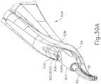
- An example of such an acoustic assembly (1000)is shown in FIGS. 34A and 34B .
- Acoustic assembly (1000)comprises ultrasonic blade (42), waveguide (80), and ultrasonic transducer assembly (12).
- waveguide (80)is secured within shaft assembly (30) via pin (32), which passes through waveguide (80) and shaft assembly (30).
- a featuremay be provided which allows a user to disengage pin (32) from waveguide (80). It should be understood that disengaging of pin (32) from waveguide (80) will cause acoustic assembly to be disengaged from shaft assembly (30). Once disengaged, acoustic assembly (1000) may be moved longitudinally distally to thereby expose ultrasonic blade (42) and a distal portion of waveguide (80) as shown in FIG. 34B .
- ultrasonic blade (42) and the distal portion of waveguide (80)may be cleaned to thereby remove surgical debris, body fluid, etc. stuck to the exterior surface of both.
- ultrasonic blade (42) and waveguide (80)may be retracted back proximally to the position shown in FIG. 34A , and pin (32) may be re-engaged with waveguide (80).
- a wipermay project outwardly from an exterior surface of one or both of ultrasonic blade (42) or waveguide (80) such that as acoustic assembly (1000) is moved longitudinally distally, the wiper may drive surgical debris, body fluid, etc. from the interior cavity of shaft assembly (30) and/or clean an interior surface of shaft assembly (30).
- Body (22) or shaft assembly (30)may include a button or other feature to selectively disengage/re-engage pin (32) with waveguide (80).
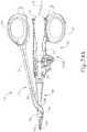
- FIGS. 35-36show one merely illustrative example of a cleaning tool (1100).
- Tool (1100)comprises a shaft (1102) having a proximal end and a distal end.
- a hook member (1110)extends laterally from the distal end of shaft (1102).
- Hook member (1110)defines an interior gap (1104) sized to fit about waveguide (80) and/or ultrasonic blade (42).
- an exterior surface of hook member (1110)is sized to fit within the interior cavity of shaft assembly (30).
- a plurality of bristles (1106)extend inwardly and outwardly from hook member (1110) such that as hook member (1110) is positioned about ultrasonic blade (42) within the interior cavity of shaft assembly (30), bristles (1106) contact the surfaces of shaft assembly (30), waveguide (80), and ultrasonic blade (42) to thereby clean them.
- shaft (1102) and/or hook member (1110) of tool (1100)may be flexible.
- hook member (1110)may be resiliently biased to assume the configuration shown in FIGS. 35 and 36 ; yet still be deformable to some degree.
- FIGS. 37 and 38show an exemplary alternative tool (1120).
- Tool (1120)comprises a hollow shaft (1122) having a proximal end and a distal end.
- Hollow shaft (1122)defines an interior bore (1124) sized to fit about waveguide (80) and ultrasonic blade (42).
- an exterior surface of hollow shaft (1122)is sized to fit within the interior cavity of shaft assembly (30).
- a plurality of bristles (1126)extend inwardly and outwardly from the distal end of hollow shaft (1122) such that as hollow shaft (1122) is positioned about waveguide (80) and ultrasonic blade (42) within the interior cavity of shaft assembly (30), bristles (1126) contact the surfaces of shaft assembly (30), waveguide (80), and ultrasonic blade (42) to thereby clean them.
- hollow shaft (1122)may be flexible or resilient.
- FIGS. 39 and 40show an exemplary alternative tool (1130).
- Tool (1130)comprises a torque device (1132) having a tab (1131) extending from a distal end of torque device (1132).
- Torque device (1132)may be configured and operable in accordance with at least some of the teachings of U.S. Pub. No. 2007/0191713 , entitled “Ultrasonic Device for Cutting and Coagulating,” published August 16, 2007.
- longitudinal slots (1134)may be formed in an exemplary cap (1133) of instrument (10). Longitudinal slots (1134) pass completely through cap (1133).
- Longitudinal slots (1134)allow for tab (1131) of tool (1130) to pass through into the interior cavity of shaft assembly (30) to thereby scrape and/or otherwise clean any surgical debris and/or body fluid (2) from the interior cavity of shaft assembly (30).
- Tab (1131)may be moved longitudinally within longitudinal slots (1134). It should be understood that tab (1131) may comprise bristles, a wiper, and/or any other suitable feature(s) to provide for cleaning of surgical debris, body fluid, etc. from the interior cavity of shaft assembly (30).
- Versions of the devices described abovemay have application in conventional medical treatments and procedures conducted by a medical professional, as well as application in robotic-assisted medical treatments and procedures.
- various teachings hereinmay be readily incorporated into a robotic surgical system such as the DAVINCITM system by Intuitive Surgical, Inc., of Sunnyvale, California.
- DAVINCITM systemby Intuitive Surgical, Inc., of Sunnyvale, California.
- teachings hereinmay be readily combined with various teachings of U.S. Pat. No. 6,783,524 , entitled “Robotic Surgical Tool with Ultrasound Cauterizing and Cutting Instrument,” published August 31, 2004.
- Versions described abovemay be designed to be disposed of after a single use, or they can be designed to be used multiple times. Versions may, in either or both cases, be reconditioned for reuse after at least one use. Reconditioning may include any combination of the steps of disassembly of the device, followed by cleaning or replacement of particular pieces, and subsequent reassembly. In particular, some versions of the device may be disassembled, and any number of the particular pieces or parts of the device may be selectively replaced or removed in any combination. Upon cleaning and/or replacement of particular parts, some versions of the device may be reassembled for subsequent use either at a reconditioning facility, or by a user immediately prior to a procedure.
- reconditioning of a devicemay utilize a variety of techniques for disassembly, cleaning/replacement, and reassembly. Use of such techniques, and the resulting reconditioned device, are all within the scope of the present application.
- versions described hereinmay be sterilized before and/or after a procedure.
- the deviceis placed in a closed and sealed container, such as a plastic or TYVEK bag.
- the container and devicemay then be placed in a field of radiation that can penetrate the container, such as gamma radiation, x-rays, or high-energy electrons.
- the radiationmay kill bacteria on the device and in the container.
- the sterilized devicemay then be stored in the sterile container for later use.
- a devicemay also be sterilized using any other technique known in the art, including but not limited to beta or gamma radiation, ethylene oxide, or steam.
Landscapes
- Health & Medical Sciences (AREA)
- Surgery (AREA)
- Life Sciences & Earth Sciences (AREA)
- Engineering & Computer Science (AREA)
- Heart & Thoracic Surgery (AREA)
- Veterinary Medicine (AREA)
- Nuclear Medicine, Radiotherapy & Molecular Imaging (AREA)
- Biomedical Technology (AREA)
- Public Health (AREA)
- Medical Informatics (AREA)
- Molecular Biology (AREA)
- Animal Behavior & Ethology (AREA)
- General Health & Medical Sciences (AREA)
- Dentistry (AREA)
- Mechanical Engineering (AREA)
- Oral & Maxillofacial Surgery (AREA)
- Pathology (AREA)
- Otolaryngology (AREA)
- Surgical Instruments (AREA)
Description
- A variety of surgical instruments include an end effector having a blade element that vibrates at ultrasonic frequencies to cut and/or seal tissue (e.g., by denaturing proteins in tissue cells). These instruments include one or more piezoelectric elements that convert electrical power into ultrasonic vibrations, which are communicated along an acoustic waveguide to the blade element. The precision of cutting and coagulation may be controlled by the surgeon's technique and adjusting the power level, blade edge angle, tissue traction, and blade pressure.
- Examples of ultrasonic surgical instruments include the HARMONIC ACE® Ultrasonic Shears, the HARMONIC WAVE® Ultrasonic Shears, the HARMONIC FOCUS® Ultrasonic Shears, and the HARMONIC SYNERGY® Ultrasonic Blades, all by Ethicon Endo-Surgery, Inc. of Cincinnati, Ohio. Further examples of such devices and related concepts are disclosed in
U.S. Pat. No. 5,322,055 , entitled "Clamp Coagulator/Cutting System for Ultrasonic Surgical Instruments," issued June 21, 1994;U.S. Pat. No. 5,873,873 , entitled "Ultrasonic Clamp Coagulator Apparatus Having Improved Clamp Mechanism," issued February 23, 1999;U.S. Pat. No. 5,980,510 , entitled "Ultrasonic Clamp Coagulator Apparatus Having Improved Clamp Arm Pivot Mount," filed October 10, 1997;U.S. Pat. No. 6,325,811 , entitled "Blades with Functional Balance Asymmetries for use with Ultrasonic Surgical Instruments," issued December 4, 2001;U.S. Pat. No. 6,773,444 , entitled "Blades with Functional Balance Asymmetries for Use with Ultrasonic Surgical Instruments," issued August 10, 2004; andU.S. Pat. No. 6,783,524 , entitled "Robotic Surgical Tool with Ultrasound Cauterizing and Cutting Instrument," issued August 31, 2004. - Still further examples of ultrasonic surgical instruments are disclosed in
U.S. Pub. No. 2006/0079874 , entitled "Tissue Pad for Use with an Ultrasonic Surgical Instrument," published April 13, 2006;U.S. Pub. No. 2007/0191713 , entitled "Ultrasonic Device for Cutting and Coagulating," published August 16, 2007;U.S. Pub. No. 2007/0282333 , entitled "Ultrasonic Waveguide and Blade," published December 6, 2007,;U.S. Pub. No. 2008/0200940 , entitled "Ultrasonic Device for Cutting and Coagulating," published August 21, 2008;U.S. Pub. No. 2009/0105750 , entitled "Ergonomic Surgical Instruments," published April 23, 2009;U.S. Pub. No. 2010/0069940 , entitled "Ultrasonic Device for Fingertip Control," published March 18, 2010; andU.S. Pub. No. 2011/0015660 , entitled "Rotating Transducer Mount for Ultrasonic Surgical Instruments," published January 20, 2011;U.S. Pub. No. 2012/0029546 , entitled "Ultrasonic Surgical Instrument Blades," published February 2, 2012; and U.S. Pat. App. No.14/031,665 - Some ultrasonic surgical instruments may include a cordless transducer such as that disclosed in
U.S. Pub. No. 2012/0112687 , entitled "Recharge System for Medical Devices," published May 10, 2012,U.S. Pub. No. 2012/0116265 , entitled "Surgical Instrument with Charging Devices," published May 10, 2012; and/orU.S. Pat. App. No. 61/410,603, filed November 5, 2010 - Additionally, some ultrasonic surgical instruments may include an articulating shaft section. Examples of such ultrasonic surgical instruments are disclosed in
U.S. Pat. App. No. 13/538,588, filed June 29, 2012 U.S. Pat. App. No. 13/657,553, filed October 22, 2012 - Some ultrasonic surgical instruments may include a clamp feature to press tissue against the ultrasonic blade of the end effector. Examples of such an arrangement (sometimes referred to as a clamp coagulator shears or an ultrasonic transector) is disclosed in
U.S. Pat. No. 5,322,055 , entitled "Clamp Coagulator/Cutting System for Ultrasonic Surgical Instruments," issued June 21, 1994;U.S. Pat. No. 5,873,873 , entitled "Ultrasonic Clamp Coagulator Apparatus Having Improved Clamp Mechanism," issued February 23, 1999; andU.S. Pat. No. 6,325,811 , entitled "Blades with Functional Balance Asymmetries for use with Ultrasonic Surgical Instruments," issue December 4, 2001. Some versions of clamp coagulator shears utilize handles that are either of a pistol or scissors grips design. The scissor grip designs may have one thumb or finger grip that is immovable and fixed to the housing; and one movable thumb or finger grip. Some designs have scissor arms that extend from the grips, with one of the arms rotating around a fixed pivot or rotation point that is perpendicular to the longitudinal axis of the working element. The operator may thus squeeze a handgrip or other feature to drive a clamp arm, to thereby press the clamp pad toward the blade. US 5,935,144 A discusses another related ultrasonic surgical instrument, which includes an improved acoustic isolation element which seals the distal end of the instrument to reduce or eliminate penetration by liquids or other contaminants.- While several surgical instruments and systems have been made and used, it is believed that no one prior to the inventors has made or used the invention described in the appended claims.
- While the specification concludes with claims which particularly point out and distinctly claim this technology, it is believed this technology will be better understood from the following description of certain examples taken in conjunction with the accompanying drawings, in which like reference numerals identify the same elements. Exemplary embodiments of the invention as defined in the appended claims are described in conjunction with
Fig. 20-22 ,23A , and23B . Other figures that are described herein illustrate other components of a surgical instrument or embodiments that are not claimed. FIG. 1 depicts a perspective view of an exemplary surgical instrument;FIG. 2 depicts an exploded perspective view of the instrument ofFIG. 1 ;FIG. 3 depicts a side elevational view of the end effector of the instrument ofFIG. 1 ;FIG. 4 depicts a perspective view of the end effector of the instrument ofFIG. 1 ;FIG. 5 depicts a partial cross-sectional view of a variation of the instrument ofFIG. 1 having an exemplary sealing element;FIG. 6 depicts a partial cross-sectional view of a variation of the instrument ofFIG. 1 having an exemplary alternative sealing element;FIG. 7 depicts a partial cross-sectional view of a variation of the instrument ofFIG. 1 having another exemplary alternative sealing element;FIG. 8 depicts a partial cross-sectional view of a variation of the instrument ofFIG. 1 having yet another exemplary alternative sealing element;FIG. 9 depicts a partial cross-sectional view of a variation of the instrument ofFIG. 1 having yet another exemplary alternative sealing element;FIG. 10 depicts a partial cross-sectional view of a variation of the instrument ofFIG. 1 having yet another exemplary alternative sealing element;FIG. 11 depicts a side elevational view of an exemplary alternative surgical instrument;FIG. 12A depicts a cross-sectional view of the instrument ofFIG. 11 with a cleaning element in a first longitudinal position;FIG. 12B depicts a cross-sectional view of the instrument ofFIG. 11 with the cleaning element ofFIG. 12A still in the first longitudinal position, and with tissue disposed within an end effector of the instrument;FIG. 12C depicts a cross-sectional view of the instrument ofFIG. 11 with the cleaning element ofFIG. 12A moved to a second longitudinal position, and with the tissue being forced from the end effector of the instrument;FIG. 12D depicts a cross-sectional view of the instrument ofFIG. 11 with the cleaning element ofFIG. 12A moved back to the first longitudinal position;FIG. 13 depicts a perspective view of an end effector of another exemplary alternative surgical instrument;FIG. 14 depicts a cross-sectional view of the end effector ofFIG. 13 taken along line 14-14 ofFIG. 13 ;FIG. 15A depicts a cross-sectional view of the instrument ofFIG. 13 with an exemplary alternative cleaning element in a first position;FIG. 15B depicts a cross-sectional view of the instrument ofFIG. 13 with the cleaning element ofFIG. 15A moved to a second position;FIG. 16 depicts a perspective view of an end effector of yet another exemplary alternative surgical instrument;FIG. 17A depicts a cross-sectional view of the instrument ofFIG. 16 with a clamp arm of the instrument in a first position;FIG. 17B depicts a cross-sectional view of the instrument ofFIG. 16 with the clamp arm ofFIG. 17A moved to a second position;FIG. 17C depicts a cross-sectional view of the instrument ofFIG. 16 with the clamp arm ofFIG. 17A moved to a third position;FIG. 18 depicts a perspective view of an exemplary shaft assembly operable to be used with the instrument ofFIG. 1 ;FIG. 19 depicts a cross-sectional view of a variation of the instrument ofFIG. 1 having the shaft assembly ofFIG. 18 disposed within a container of fluid;FIG. 20 depicts a cross-sectional view of an alternative cleaning element suitable for a surgical instrument according to the present invention;FIG. 21 depicts a cross-sectional view of the cleaning element ofFIG. 20 ;FIG. 22 depicts a cross-sectional view of yet another alternative cleaning element suitable for a surgical instrument according to the present invention;FIG. 23A depicts a cross-sectional view of the cleaning element ofFIG. 22 in a first rotational position;FIG. 23B depicts a cross-sectional view of the cleaning element ofFIG. 22 moved to a second rotational position;FIG. 24 depicts a cross-sectional view of an exemplary protective element;FIG. 25 depicts a perspective view of an exemplary alternative protective element;FIG. 26 depicts a cross-sectional view of the protective element ofFIG. 25 positioned within the instrument ofFIG. 1 ;FIG. 27 depicts a perspective view of another exemplary alternative protective element;FIG. 28 depicts a perspective view of yet another exemplary alternative protective element;FIG. 29 depicts a perspective view of an exemplary end cap;FIG. 30A depicts a perspective view of the end cap ofFIG. 29 positioned on the end of yet another exemplary alternative instrument;FIG. 30B depicts a perspective view of the instrument ofFIG. 30A with the end cap ofFIG. 29 removed;FIG. 31 depicts a perspective view of an exemplary alternative end cap;FIG. 32 depicts a perspective view of the end cap ofFIG. 31 positioned on the end of yet another exemplary alternative instrument;FIG. 33 depicts a perspective view of the end cap ofFIG. 31 positioned on the end of yet another exemplary alternative instrument with a vacuum conduit positioned about a distal end of the end cap;FIG. 34A depicts a side elevational view of yet another exemplary alternative instrument with an acoustic assembly in a first longitudinal position;FIG. 34B depicts a side elevational view of the instrument ofFIG. 34A with the acoustic assembly moved to a second longitudinal position;FIG. 35 depicts a side elevational view of an exemplary cleaning instrument;FIG. 36 depicts a cross-sectional view of the cleaning instrument ofFIG. 35 taken along line 36-36 ofFIG. 35 ;FIG. 37 depicts a side elevational view of an exemplary alternative cleaning instrument;FIG. 38 depicts a cross-sectional view of the cleaning instrument ofFIG. 35 taken along line 38-38 ofFIG. 37 ;FIG. 39 depicts a perspective view of a torquing device having yet another exemplary cleaning element; andFIG. 40 depicts a perspective view of the torquing device ofFIG. 39 with the cleaning element positioned within an end effector of yet another exemplary alternative surgical instrument.- The drawings are not intended to be limiting in any way, and it is contemplated that various embodiments of the technology may be carried out in a variety of other ways, including those not necessarily depicted in the drawings. The accompanying drawings incorporated in and forming a part of the specification illustrate several aspects of the present technology, and together with the description serve to explain the principles of the technology; it being understood, however, that this technology is not limited to the precise arrangements shown.
- The following description of certain examples of the technology should not be used to limit its scope. Other examples, features, aspects, embodiments, and advantages of the technology will become apparent to those skilled in the art from the following description, which is by way of illustration, one of the best modes contemplated for carrying out the technology. As will be realized, the technology described herein is capable of other different and obvious aspects, all without departing from the technology. Accordingly, the drawings and descriptions should be regarded as illustrative in nature and not restrictive.
- It is further understood that any one or more of the teachings, expressions, embodiments, examples, etc. described herein may be combined with any one or more of the other teachings, expressions, embodiments, examples, etc. that are described herein. The following-described teachings, expressions, embodiments, examples, etc. should therefore not be viewed in isolation relative to each other. Various suitable ways in which the teachings herein may be combined will be readily apparent to those of ordinary skill in the art in view of the teachings herein.
- For clarity of disclosure, the terms "proximal" and "distal" are defined herein relative to a surgeon or other operator grasping a surgical instrument having a distal surgical end effector. The term "proximal" refers the position of an element closer to the surgeon or other operator and the term "distal" refers to the position of an element closer to the surgical end effector of the surgical instrument and further away from the surgeon or other operator.
FIG. 1 illustrates an exemplary ultrasonic surgical instrument (10). At least part of instrument (10) may be constructed and operable in accordance with at least some of the teachings ofU.S. Pat. No. 5,322,055 ;U.S. Pat. No. 5,873,873 ;U.S. Pat. No. 5,980,510 ;U.S. Pat. No. 6,325,811 ;U.S. Pat. No. 6,783,524 ;U.S. Pub. No. 2006/0079874 ;U.S. Pub. No. 2007/0191713 ;U.S. Pub. No. 2007/0282333 ;U.S. Pub. No. 2008/0200940 ;U.S. Pub. No. 2010/0069940 ;U.S. Pub. No. 2011/0015660 ;U.S. Pub. No. 2012/0112687 ;U.S. Pub. No. 2012/0116265 ;U.S. Pat. App. No. 13/538,588 ;U.S. Pat. App. No. 13/657,553 ;U.S. Pat. App. No. 61/410,603 U.S. Pat. App. No. 14/031,665 . As described therein and as will be described in greater detail below, instrument (10) is operable to cut tissue and seal or weld tissue (e.g., a blood vessel, etc.) substantially simultaneously, using a combination of compression and ultrasonic vibrational energy. It should also be understood that instrument (10) may have various structural and functional similarities with the HARMONIC ACE® Ultrasonic Shears, the HARMONIC WAVE® Ultrasonic Shears, the HARMONIC FOCUS® Ultrasonic Shears, and/or the HARMONIC SYNERGY® Ultrasonic Blades. Furthermore, instrument (10) may have various structural and functional similarities with the devices taught in any of the other references that are cited.- To the extent that there is some degree of overlap between the teachings of the references cited herein, the HARMONIC ACE® Ultrasonic Shears, the HARMONIC WAVE® Ultrasonic Shears, the HARMONIC FOCUS® Ultrasonic Shears, and/or the HARMONIC SYNERGY® Ultrasonic Blades, and the following teachings relating to instrument (10), there is no intent for any of the description herein to be presumed as admitted prior art. Several teachings herein will in fact go beyond the scope of the teachings of the references cited herein and the HARMONIC ACE® Ultrasonic Shears, the HARMONIC WAVE® Ultrasonic Shears, the HARMONIC FOCUS® Ultrasonic Shears, and the HARMONIC SYNERGY® Ultrasonic Blades.
- Instrument (10) of the present example comprises a handpiece (20), a shaft assembly (30), and an end effector (40). Handpiece (20) comprises a body (22) including a finger grip (24) and a pair of buttons (26). Instrument (10) also includes a clamp arm assembly (50) that is pivotable toward and away from body (22). A proximal portion of clamp arm assembly (50) comprises a thumb grip (52). Thumb grip (52) and finger grip (24) together provide a scissor grip type of configuration. It should be understood, however, that various other suitable configurations may be used, including but not limited to a pistol grip configuration. A cap (33) is secured to a distal end of shaft assembly (30). End effector (40) includes an ultrasonic blade (42) extending distally from cap (33) of shaft assembly (30); and a pivoting clamp arm (54), which is an integral feature of clamp arm assembly (50). Clamp arm assembly (50) is pivotably coupled to a projection (34) extending laterally from shaft assembly (30) via a pivot member (36) (e.g., a pin, bearing, shaft, etc.) such that clamp arm (54) is pivotable toward and away from ultrasonic blade (42) to thereby clamp tissue between a clamp pad (55) of clamp arm (54) and ultrasonic blade (42). As best seen in
FIG. 3 , clamp arm assembly (50) is pivotably coupled to projection (34) such that clamp arm assembly (50) pivots about an axis offset from a longitudinal axis (LAI). It should be understood that such rotation about an offset axis may allow for a narrower shaft assembly (30) profile. It should be understood that shaft assembly (30) passes through a portion of clamp arm assembly (50) such that as clamp arm assembly (50) rotates, clamp arm (54) rotates about a portion of shaft assembly (30). In particular, a first member (53A) and a second member (53B) of clamp arm assembly (50) are disposed about a distal portion of shaft assembly (30). - Clamp arm assembly (50) is configured such that clamp arm (54) is pivotable toward ultrasonic blade (42) in response to pivoting of thumb grip (52) of clamp arm assembly (50) toward body (22); and such that clamp arm (54) is pivotable away from ultrasonic blade (42) in response to pivoting of thumb grip (52) of clamp arm assembly (50) away from body (22). As best seen in
FIG. 2 , a proximal end of clamp arm (54) is disposed within a distal recess (56) of a shank portion (51) of clamp arm assembly (50); and is secured therein by a pin (58). Various other suitable ways in which clamp arm (54) may be integrated into clamp arm assembly (50) will be apparent to those of ordinary skill in the art in view of the teachings herein. In some versions, one or more resilient members are used to bias clamp arm (54) and/or trigger (28) to the open position shown inFIG. 1 . By way of example only, such a resilient member may comprise a leaf spring, a torsion spring, and/or any other suitable kind of resilient member. - As shown in
FIG. 1 , an ultrasonic transducer assembly (12) extends proximally from body (22) of handpiece (20). Transducer assembly (12) is coupled with a generator (16) via a cable (14). Transducer assembly (12) receives electrical power from generator (16) and converts that power into ultrasonic vibrations through piezoelectric principles. Generator (16) may include a power source and control module that is configured to provide a power profile to transducer assembly (12) that is particularly suited for the generation of ultrasonic vibrations through transducer assembly (12). By way of example only, generator (16) may comprise aGEN 300 sold by Ethicon Endo-Surgery, Inc. of Cincinnati, Ohio. In addition or in the alternative, generator (16) may be constructed in accordance with at least some of the teachings ofU.S. Pub. No. 2011/0087212 , entitled "Surgical Generator for Ultrasonic and Electrosurgical Devices," published April 14, 2011. It should also be understood that at least some of the functionality of generator (16) may be integrated into handpiece (20), and that handpiece (20) may even include a battery or other on-board power source such that cable (14) is omitted. Still other suitable forms that generator (16) may take, as well as various features and operabilities that generator (16) may provide, will be apparent to those of ordinary skill in the art in view of the teachings herein. - Ultrasonic vibrations that are generated by transducer assembly (12) are communicated along an acoustic waveguide (80), which extends through shaft assembly (30) to reach ultrasonic blade (42) as shown in
FIG. 2 . Waveguide (80) is secured within shaft assembly (30) via a pin (32), which passes through waveguide (80) and shaft assembly (30). Pin (32) is located at a position along the length of waveguide (80) corresponding to a node associated with resonant ultrasonic vibrations communicated through waveguide (80). As noted above, when ultrasonic blade (42) is in an activated state (i.e., vibrating ultrasonically), ultrasonic blade (42) is operable to effectively cut through and seal tissue, particularly when the tissue is being clamped between clamp arm (54) and ultrasonic blade (42). It should be understood that waveguide (80) may be configured to amplify mechanical vibrations transmitted through waveguide (80). Furthermore, waveguide (80) may include features operable to control the gain of the longitudinal vibrations along waveguide (80) and/or features to tune waveguide (80) to the resonant frequency of the system. - In the present example, the distal end of ultrasonic blade (42) is located at a position corresponding to an anti-node associated with resonant ultrasonic vibrations communicated through waveguide (80), in order to tune the acoustic assembly to a preferred resonant frequency fo when the acoustic assembly is not loaded by tissue. When transducer assembly (12) is energized, the distal end of ultrasonic blade (42) is configured to move longitudinally in the range of, for example, approximately 10 to 500 microns peak-to-peak, and in some instances in the range of about 20 to about 200 microns at a predetermined vibratory frequency fo of, for example, 55.5 kHz. When transducer assembly (12) of the present example is activated, these mechanical oscillations are transmitted through the waveguide to reach ultrasonic blade (42), thereby providing oscillation of ultrasonic blade (42) at the resonant ultrasonic frequency. Thus, when tissue is secured between ultrasonic blade (42) and clamp arm (54), the ultrasonic oscillation of ultrasonic blade (42) may simultaneously sever the tissue and denature the proteins in adjacent tissue cells, thereby providing a coagulative effect with relatively little thermal spread. In some versions, an electrical current may also be provided through ultrasonic blade (42) and clamp arm (54) to also cauterize the tissue. While some configurations for an acoustic transmission assembly and transducer assembly (12) have been described, still other suitable configurations for an acoustic transmission assembly and transducer assembly (12) will be apparent to one or ordinary skill in the art in view of the teachings herein. Similarly, other suitable configurations for end effector (40) will be apparent to those of ordinary skill in the art in view of the teachings herein.
- An operator may activate buttons (26) to selectively close switches (27) (see
FIG. 2 ), thereby selectively activating transducer assembly (12) to activate ultrasonic blade (42). In the present example, two buttons (26) are provided - one for activating ultrasonic blade (42) at a low power and another for activating ultrasonic blade (42) at a high power. However, it should be understood that any other suitable number of buttons and/or otherwise selectable power levels may be provided. For instance, a foot pedal may be provided to selectively activate transducer assembly (12). Buttons (26) of the present example are positioned such that an operator may readily fully operate instrument (10) with a single hand. For instance, the operator may position their thumb in the ring formed by thumb grip (52), position their middle or ring finger in the ring formed by finger grip (24), and manipulate buttons (26) using their index finger. Of course, any other suitable techniques may be used to grip and operate instrument (10); and buttons (26) may be located at any other suitable positions. - The foregoing components and operabilities of instrument (10) are merely illustrative. Instrument (10) may be configured in numerous other ways as will be apparent to those of ordinary skill in the art in view of the teachings herein. By way of example only, at least part of instrument (10) may be constructed and/or operable in accordance with at least some of the teachings of any of the following:
U.S. Pat. No. 5,322,055 ;U.S. Pat. No. 5,873,873 ;U.S. Pat. No. 5,980,510 ;U.S. Pat. No. 6,325,811 ;U.S. Pat. No. 6,783,524 ;U.S. Pub. No. 2006/0079874 ;U.S. Pub. No. 2007/0191713 ;U.S. Pub. No. 2007/0282333 ;U.S. Pub. No. 2008/0200940 ;U.S. Pub. No. 2010/0069940 ;U.S. Pub. No. 2011/0015660 ;U.S. Pub. No. 2012/0112687 ;U.S. Pub. No. 2012/0116265 ;U.S. Pat. App. No. 13/538,588 ;U.S. Pat. App. No. 13/657,553 ; and/orU.S. Pat. App. No. 14/031,665 . Additional merely illustrative variations for instrument (10) will be described in greater detail below. It should be understood that the below described variations may be readily applied to instrument (10) described above and any of the instruments referred to in any of the references that are cited herein, among others. - As shown in
FIG. 4 , an opening (33A) exists at a distal end of shaft assembly (30) between an exterior surface of ultrasonic blade (42) and an interior surface of cap (33). Opening (33A) provides access to an interior cavity of shaft assembly (30). The interior cavity is defined between an interior surface of shaft assembly (30) (including cap (33)) and exterior surfaces of waveguide (80) and ultrasonic blade (42). It may be desirable to provide features that seal this interior cavity such that surgical debris (e.g. tissue, coagulated blood, etc.), body fluid, etc. is prevented from entering. In particular, it may be desirable to provide a seal that extends between the exterior surface of waveguide (80) and/or ultrasonic blade (42) and the interior surface of cap (33). Although the examples of radial seals discussed below are discussed as contacting one or both of the exterior surfaces of waveguide (80) and/or ultrasonic blade (42), it should be understood that any radial seal discussed below may contact either or both of the exterior surfaces of waveguide (80) and/or ultrasonic blade (42). - An example of a radial seal (100) is shown in
FIG. 5 . Radial seal (100) comprises a circular-resilient member having a semi-circular cross-sectional profile. The semi-circular cross-sectional profile of radial seal (100) presents a concave interior surface and a convex exterior surface. Radial seal (100) contacts the exterior surface of waveguide (80) along a pair of edges (100A, 100B) of radial seal (100). Radial seal (100) contacts the interior surface of cap (33) at an apex (100C) of the exterior convex surface of radial seal (100). It should be understood that these contact points extend completely circumferentially about the exterior surface of waveguide (80) and the interior surface of cap (33). - Radial seal (100) defines a height (H1) between pair of edges (100A, 100B) and apex (100C). The interior cavity of shaft assembly (30) has a height (H2) represented by the distance between the exterior surface of waveguide (80) and the interior surface of cap (33). When placed within opening (33A), radial seal (100) flexes to assume height (H2) of the interior cavity of shaft assembly (30). Radial seal (100) may be configured such that height (H1) of radial seal (100) is greater than height (H2) of the interior cavity of shaft assembly (30). Furthermore, radial seal (100) may be resiliently biased to return to height (H1). It should be understood that this bias would cause radial seal (100) to apply force to the exterior surface of waveguide (80) via pair of edges (100A, 100B) and to the interior surface of cap (33) via apex (100C). It should further be understood that the resilient bias of radial seal (100) may be changed to apply more or less force to the exterior surface of waveguide (80) and/or the interior surface of cap (33). Radial seal (100) may be configured and positioned such that pair of edges (100A, 100B) contacts waveguide (80) at a node associated with resonant ultrasonic vibrations communicated through waveguide (80) and ultrasonic blade (42). Alternatively, radial seal (100) may be configured and positioned such that pair of edges (100A, 100B) contacts waveguide (80) away from a node associated with resonant ultrasonic vibrations communicated through waveguide (80) and ultrasonic blade (42).
- As will be appreciated form the discussion below, in some versions of instrument (10), radial seal (100) may be configured to be longitudinally translatable such that pair of edges (100A, 100B) and/or apex (100C) of radial seal (100) may be used as a cleaning element to drive surgical debris, body fluid, etc. from the interior cavity of shaft assembly (30) (including cap (33)) and/or clean the exterior surface of waveguide (80), ultrasonic blade (42), and/or the interior surface of shaft assembly (30) (including cap (33)).
- Although radial seal (100) of the present example contacts the exterior surface of waveguide (80), it should be understood that radial seal (100) may alternatively contact the exterior surface of ultrasonic blade (42).
FIG. 6 shows an exemplary alternative radial seal (110) that is configured to extend between the exterior surface of waveguide (80) and the interior surface of cap (33) to thereby seal the interior cavity of shaft assembly (30). Radial seal (110) comprises a circular base (112) and a plurality of bristles (114). An exterior surface of circular base (112) is secured to the interior surface of cap (33). Bristles (114) are secured to an interior surface of base (112) and extend inwardly to the exterior surface of waveguide (80). It should be understood, however, that radial seal (110) may be reconfigured such that the exterior surface of circular base (112) may be secured to the exterior surface of waveguide (80), with bristles (114) extending outwardly to the interior surface of cap (33). It should be understood that solid and/or semi-solid surgical debris (e.g. tissue, coagulated blood, etc.) may not pass through bristles (114) while fluid may still pass through bristles (114). Bristles (114) may comprise nylon and/or another other appropriate material. A stiffness of each bristle (114) may be changed to thereby prevent more or less material from passing through. Also, bristles (114) may be arranged in a more or less dense configuration to thereby prevent more or less material from passing through. Radial seal (110) may be positioned such that bristles (114) contact waveguide (80) at a node associated with resonant ultrasonic vibrations communicated through waveguide (80) and ultrasonic blade (42). Alternatively, radial seal (110) may be positioned such that bristles (114) contacts waveguide (80) away from a node associated with resonant ultrasonic vibrations communicated through waveguide (80) and ultrasonic blade (42).- As will be appreciated form the discussion below, in some versions of instrument (10), radial seal (110) may be configured to be longitudinally translatable such that bristles (114) of radial seal (110) may be used as a cleaning element to drive surgical debris, body fluid, etc. from the interior cavity of shaft assembly (30) (including cap (33)) and/or clean the exterior surface of waveguide (80), ultrasonic blade (42), and/or the interior surface of shaft assembly (30) (including cap (33)).
- Although radial seal (110) of the present example contacts the exterior surface of waveguide (80), it should be understood that radial seal (110) may alternatively contact the exterior surface of ultrasonic blade (42).
FIG. 7 shows another exemplary alternative radial seal (120) that is configured to extend between the exterior surface of ultrasonic blade (42) and the interior surface of cap (33) to thereby seal the interior cavity of shaft assembly (30). Radial seal (120) comprises a circular member made of an absorbent material having a rectangular cross-sectional profile. Radial seal (120) is sized such that an exterior surface (122) of radial seal (120) contacts the interior surface of cap (33) and such that an interior surface (124) of radial seal (120) contacts the exterior surface of ultrasonic blade (42). The absorbent material of radial seal (120) may comprise felt and/or any other appropriate material. The absorbent material of radial seal (120) may be porous such that solid and/or semi-solid surgical debris may not pass through radial seal (120) whereas fluid may still pass through radial seal (120). A density of the absorbent material of radial seal (120) may be changed to thereby prevent more or less material from passing through. It should be understood that radial seal (120) may comprise a nonabsorbent/nonporous material to thereby prevent all surgical debris, body fluid, etc. from entering the interior cavity of shaft assembly (30).- Radial seal (120) defines a height (H3) between interior surface (124) and exterior surface (122). As previously discussed, the interior cavity of shaft assembly (30) has a height (H2) represented by the distance between the exterior surface of ultrasonic blade (42) and the interior surface of cap (33). Radial seal (120) of the present example comprises a flexible material. When placed within opening (33A), radial seal (120) flexes to assume height (H2) of the interior cavity of shaft assembly (30). Radial seal (120) may be configured such that height (H3) of radial seal (120) is greater than height (H2) of the interior cavity of shaft assembly (30). Furthermore, the flexible material of radial seal (120) may cause radial seal (120) to be resiliently biased to return to height (H3). It should be understood that this bias would cause radial seal (120) to apply force to the exterior surface of ultrasonic blade (42) via interior surface (124) and to the interior surface of cap (33) via exterior surface (122). It should further be understood that the resilient bias of radial seal (120) may be changed by changing the flexible material to apply more or less force to the exterior surface of ultrasonic blade (42) and/or the interior surface of cap (33). Radial seal (120) may be positioned such that interior surface (124) contacts ultrasonic blade (42) at a node associated with resonant ultrasonic vibrations communicated through waveguide (80) and ultrasonic blade (42). Alternatively, radial seal (120) may be positioned such that interior surface (124) contacts ultrasonic blade (42) away from a node associated with resonant ultrasonic vibrations communicated through waveguide (80) and ultrasonic blade (42).
- As will be appreciated form the discussion below, in some versions of instrument (10), radial seal (120) may be configured to be longitudinally translatable such that exterior surface (122) and/or interior surface (124) of radial seal (120) may be used as a cleaning element to drive surgical debris, body fluid, etc. from the interior cavity of shaft assembly (30) (including cap (33)) and/or clean the exterior surface of waveguide (80), ultrasonic blade (42), and/or the interior surface of shaft assembly (30) (including cap (33)).
- Although radial seal (120) of the present example contacts the exterior surface of ultrasonic blade (42), it should be understood that radial seal (120) may alternatively contact the exterior surface of waveguide (80).
FIG. 8 shows another exemplary alternative radial seal (130) that is configured to extend between the exterior surface of ultrasonic blade (42) and the interior surface of cap (33) to thereby seal the interior cavity of shaft assembly (30). Radial seal (130) comprises a circular member made of a flexible material having a circular cross-sectional profile (e.g. similar to an o-ring). Radial seal (130) is sized such that an exterior surface (132) of radial seal (130) contacts the interior surface of cap (33) and such that an interior surface (134) of radial seal (130) contacts the exterior surface of ultrasonic blade (42). Radial seal (130) defines a height (H4) between an inner most point of interior surface (130) and an outer most point of exterior surface (132). As previously discussed, the interior cavity of shaft assembly (30) has a height (H2) represented by the distance between the exterior surface of ultrasonic blade (42) and the interior surface of cap (33). When placed within opening (33A), radial seal (130) flexes to assume height (H2) of the interior cavity of shaft assembly (30). Radial seal (130) may be configured such that height (H4) of radial seal (130) is greater than height (H2) of the interior cavity of shaft assembly (30). Furthermore, the flexible material of radial seal (130) may cause radial seal (130) to be resiliently biased to return to height (H4). It should be understood that this bias would cause radial seal (130) to apply force to the exterior surface of ultrasonic blade (42) via interior surface (134) and to the interior surface of cap (33) via exterior surface (132). It should further be understood that the resilient bias of radial seal (130) may be changed by changing the flexible material to apply more or less force to the exterior surface of ultrasonic blade (42) and/or the interior surface of cap (33). Radial seal (130) may be positioned such that interior surface (134) contacts ultrasonic blade (42) at a node associated with resonant ultrasonic vibrations communicated through waveguide (80) and ultrasonic blade (42). Alternatively, radial seal (130) may be positioned such that interior surface (134) contacts ultrasonic blade (42) away from a node associated with resonant ultrasonic vibrations communicated through waveguide (80) and ultrasonic blade (42).- As will be appreciated form the discussion below, in some versions of instrument (10), radial seal (130) may be configured to be longitudinally translatable such that exterior surface (132) and/or interior surface (134) of radial seal (130) may be used as a cleaning element to drive surgical debris, body fluid, etc. from the interior cavity of shaft assembly (30) (including cap (33)) and/or clean the exterior surface of waveguide (80), ultrasonic blade (42), and/or the interior surface of shaft assembly (30) (including cap (33)).
- Although radial seal (130) of the present example contacts the exterior surface of ultrasonic blade (42), it should be understood that radial seal (130) may alternatively contact the exterior surface of waveguide (80).
FIG. 9 shows another exemplary alternative radial seal (140) that is configured to extend between the exterior surface of ultrasonic blade (42) and the interior surface of cap (33) to thereby seal the interior cavity of shaft assembly (30). Radial seal (140) comprises a conical member (142). A first end (142A) of conical member (142) comprises a first radial circumference. A second end (142B) of conical member (142) comprises a second radial circumference. The first radial circumference of first end (142A) is greater than the second radial circumference of second end (142B). Conical member (142) is oriented within the interior cavity of shaft assembly (30) such that first end (142A) of conical member (142) is proximal of second end (142B) of conical member (142). A lip (144) projects from an exterior surface of first end (142A) of conical member (142). Conical member (142) is sized such that lip (144) of conical member (142) contacts the interior surface of cap (33) and such that an edge (146) of second end (142B) of conical member (142) contacts the exterior surface of ultrasonic blade (42). Conical member (142) may be biased to apply force upon to the exterior surface of ultrasonic blade (42) via edge (146) and to the interior surface of cap (33) via lip (144), such that conical member (142) substantially seals the region of the interior cavity of shaft assembly (30) proximal of conical member (142).- Cap (33) of the present example comprises a plurality of openings (148). Openings (148) pass completely through cap (33). Openings (148) may comprise discrete circular openings and/or slots that extend along the circumference of cap (33) to any suitable extent. Openings (148) are formed in cap (33) distally of lip (144) such that the interior cavity of shaft assembly (30) remains sealed. As surgical debris, body fluid, etc. enters the interior cavity of shaft assembly (30) via opening (33A), the exterior surface of conical member (142) guides surgical debris, body fluid, etc. toward openings (148). Openings (148) allow for fluid to pass through into a distal portion of the interior cavity of cap (33) to thereby drive surgical debris, body fluid, etc. from the interior cavity of cap (33).
- Conical member (142) may be positioned such that edge (146) contacts ultrasonic blade (42) at a node associated with resonant ultrasonic vibrations communicated through waveguide (80) and ultrasonic blade (42). Alternatively, conical member (142) may be positioned such that edge (146) contacts ultrasonic blade (42) away from a node associated with resonant ultrasonic vibrations communicated through waveguide (80) and ultrasonic blade (42).
- As will be appreciated form the discussion below, in some versions of instrument (10), radial seal (140) may be configured to be longitudinally translatable such that lip (144) and/or edge (146) of conical member (142) may be used as a cleaning element to drive surgical debris, body fluid, etc. from the interior cavity of shaft assembly (30) (including cap (33)) and/or clean the exterior surface of waveguide (80), ultrasonic blade (42), and/or the interior surface of shaft assembly (30) (including cap (33)).
- Although conical member (142) of the present example contacts the exterior surface of ultrasonic blade (42), it should be understood that conical member (142) may alternatively contact the exterior surface of waveguide (80).
FIG. 10 shows another exemplary alternative radial seal (150) that is configured to extend between the exterior surfaces of waveguide (80) and ultrasonic blade (42) and the interior surface of cap (33) to thereby seal the interior cavity of shaft assembly (30). Radial seal (150) comprises a soft material disposed within the interior cavity of shaft assembly (30). The soft material of radial seal (140) may be configured to not interrupt or significantly dampen the ultrasonic vibrations communicated through waveguide (80). The soft material of radial seal (150) prevents surgical debris, body fluid, etc. from passing into the interior cavity of shaft assembly (30) and from contacting waveguide (80) and ultrasonic blade (42) along the portions of waveguide (80) and ultrasonic blade (42) covered by the soft material of radial seal (150). The soft material of radial seal (150) may comprise liquid repellant material to discourage accumulation of liquid within the interior cavity of shaft assembly (30). The soft material of radial seal (150) may be porous such that solid and/or semi-solid surgical debris may not pass through radial seal (150) whereas fluid may still pass through radial seal (150). A density of the soft material of radial seal (150) may be changed to thereby prevent more or less material from passing through.- Radial seal (150) may be removed from the interior cavity of shaft assembly (30) after use such that surgical debris, body fluid, etc. caught within the soft material of radial seal (150) may be removed from the interior cavity of shaft assembly (30). Thus, it should be understood that radial seal (150) may be used as a cleaning element to remove surgical debris, body fluid, etc. from the interior cavity of shaft assembly (30) (including cap (33)) and/or clean the exterior surface of waveguide (80), ultrasonic blade (42), and/or the interior surface of shaft assembly (30) (including cap (33)).
- As previously discussed, opening (33A) provides access to an interior cavity of shaft assembly (30). In addition to or in lieu of sealing off such a cavity, it may be desirable to provide cleaning elements that allow a user to drive surgical debris, body fluid, etc. from the interior cavity of shaft assembly (30) (including cap (33)) and/or clean the exterior surface of waveguide (80), ultrasonic blade (42), and/or the interior surface of shaft assembly (30) (including cap (33)). Various examples of features that may be used to clean surgical debris, body fluid, etc. from the interior cavity of shaft assembly (30) will be described in greater detail below, while other examples will be apparent to those of ordinary skill in the art in view of the teachings herein.
FIGS. 11-12D show one merely illustrative example of an instrument (210) with a cavity cleaning element (200). Instrument (210) of the present example is configured to operate substantially similar to instrument (10) discussed above except for the differences discussed below.- As shown in
FIG. 11 , instrument (210) of the present example comprises a handpiece (220), a shaft assembly (230), and an end effector (240). Handpiece (220) comprises a body (222). Instrument (210) also includes a clamp arm assembly (250) that is pivotable toward and away from body (222). A cap (233) is secured to a distal end of shaft assembly (230). End effector (240) includes an ultrasonic blade (242) extending distally from cap (233) of shaft assembly (230); and a pivoting clamp arm (254), which is an integral feature of clamp arm assembly (250). Clamp arm assembly (250) is pivotably coupled to a projection (234) extending laterally from shaft assembly (230) such that clamp arm (254) is pivotable toward and away from ultrasonic blade (242) to thereby clamp tissue between a clamp pad (255) of clamp arm (254) and ultrasonic blade (242). Ultrasonic vibrations that are generated by a transducer assembly (not shown) are communicated along an acoustic waveguide (280), which extends through shaft assembly (230) to reach ultrasonic blade (242). Ultrasonic blade (242) vibrates at ultrasonic frequencies to cut and/or seal tissue. - As shown in
FIGS. 12A-12D , cleaning element (200) comprises a circular member having a triangular cross-sectional profile. An interior surface (202) of cleaning element (200) contacts an exterior surface of waveguide (280). A proximal surface (204) of cleaning element (200) extends perpendicularly from a proximal end of interior surface (202) to an interior surface of cap (233). A distal surface (206) of cleaning element (200) extends angularly from a proximal end of interior surface (202) to the interior surface of cap (233). Proximal surface (204) and distal surface (206) come together and form an edge (208) that contacts the interior surface of cap (233). It should be understood that the contact between interior surface (202) of cleaning element (200) and the contact between edge (208) of cleaning element (200) extend completely circumferentially about the exterior surface of waveguide (280) and the interior surface of cap (233). It should further be understood that edge (208) may resiliently bear against the interior surface of cap (233) and/or that interior surface (202) may resiliently bear against the exterior surface of waveguide (280). Furthermore, cleaning element (200) need not be limited to a circular shape. Any other suitable shapes/configurations may be used. - Returning to
FIG. 11 , instrument (210) comprises a sliding trigger (244). Sliding trigger (244) is longitudinally translatable between a proximal position and a distal position within a longitudinal slot (246) formed in body (222). Cleaning element (200) is mechanically connected with sliding trigger (244) such that longitudinal translation of sliding trigger (244) causes concurrent longitudinal translation of cleaning element (200). Thus, it should be understood that interior surface (202) and edge (208) of cleaning element (200) act as wipers to clean the exterior surface of waveguide (280) and/or the interior surface of cap (233). Furthermore, as will be discussed in more detail below, longitudinal translation of cleaning element (200) drives surgical debris, body fluid, etc. from an interior cavity of shaft assembly (230). Various suitable ways in which sliding trigger (244) may be coupled within cleaning element (200) will be apparent to those of ordinary skill in the art in view of the teachings herein. FIG. 12A shows cleaning element (200) in a proximal position. In the proximal position, surgical debris (e.g. tissue, coagulated blood, etc.) and/or body fluid (2) may enter into the interior cavity of shaft assembly (230) via an opening (233A) at a distal end of cap (233) as shown inFIG. 12B . When surgical debris and/or body fluid (2) becomes disposed within the interior cavity of shaft assembly (230), the user may translate cleaning element (200) longitudinally distally by translating sliding trigger (244) longitudinally distally. As shown inFIG. 12C , longitudinal distal translation of cleaning element (200) to a distal position drives surgical debris and/or body fluid (2) distally from the interior cavity of shaft assembly (230), out through opening (233A), and thereby cleans the interior surface of cap (233) and/or the exterior surface of waveguide (280). Once surgical debris and/or body fluid (2) has been driven from the interior cavity of shaft assembly (230), cleaning element (200) may be moved back to the proximal position as shown inFIG. 12D by translating sliding trigger (244) longitudinally proximally.- Instrument (210) may be configured such that cleaning element (200) contacts waveguide (280) at a node associated with resonant ultrasonic vibrations communicated through waveguide (280) and ultrasonic blade (242) when cleaning element (200) is in the proximal position. Alternatively, instrument (210) may be configured such that cleaning element (200) contacts waveguide (280) away from a node associated with resonant ultrasonic vibrations communicated through waveguide (280) and ultrasonic blade (242) when cleaning element (200) is in the proximal position. Although cleaning element (200) of the present example contacts the exterior surface of waveguide (280), it should be understood that cleaning element (200) may alternatively contact the exterior surface of ultrasonic blade (242).
FIGS. 13-15B show an exemplary alternative instrument (310) with a cleaning element (300) configured to clean and/or drive surgical debris, body fluid, etc. from the interior cavity of a shaft assembly (330). Instrument (310) of the present example is configured to operate substantially similar to instruments (10, 210) discussed above except for the differences discussed below. As shown inFIG. 13 , instrument (310) of the present example comprises a shaft assembly (330) and an end effector (340). Instrument (310) also includes a clamp arm assembly (350) that is pivotable toward and away from shaft assembly (330). A cap (333) is secured to a distal end of shaft assembly (330). End effector (340) includes an ultrasonic blade (342) extending distally from cap (333) of shaft assembly (330); and a pivoting clamp arm (354), which is an integral feature of clamp arm assembly (350). Clamp arm assembly (350) is pivotably coupled to a projection (334) extending laterally from shaft assembly (330) such that clamp arm (354) is pivotable toward and away from ultrasonic blade (342) to thereby clamp tissue between a clamp pad (355) of clamp arm (354) and ultrasonic blade (342). Ultrasonic vibrations that are generated by a transducer assembly (not shown) are communicated along an acoustic waveguide (380), which extends through shaft assembly (330) to reach ultrasonic blade (342). Ultrasonic blade (342) vibrates at ultrasonic frequencies to cut and/or seal tissue.- As shown in
FIGS. 14-15B , cleaning element (300) comprises a body (302) pivotably coupled to clamp arm (354). Body (302) comprises a first yoke portion (302A), a curved neck (302B), and a second yoke portion (302C). First yoke portion (302A) is pivotably coupled with clamp arm (354). Curved neck (302B) extends proximally and downwardly from first yoke portion (302A). Curved neck (302B) passes through a longitudinal slot (333B) formed in a top surface of cap (333). Second yoke portion (302C) extends downwardly from a portion of curved neck (302B) disposed within an interior cavity of shaft assembly (330). Second yoke portion (302C) is shaped to complement an exterior surface of waveguide (380) and the interior surface of cap (333). In particular, second yoke portion (302C) is a C-shape and is disposed about waveguide (380). As best seen inFIG. 14 , second yoke portion (302C) is slidably coupled about waveguide (380). FIG. 15A shows cleaning element (300) in a proximal position. Cleaning element (300) in the proximal position corresponds to clamp arm (354) being pivoted toward ultrasonic blade (342) such that clamp pad (355) of clamp arm (354) contacts ultrasonic blade (342). With cleaning element (300) in the proximal position, surgical debris, body fluid, etc. may enter into the interior cavity of shaft assembly (330) via an opening (333A) at a distal end of cap (333). As shown inFIG. 15B , as clamp arm (354) is rotated away from ultrasonic blade (342), because second yoke portion (302C) of body (302) of cleaning element (300) is slidably coupled about waveguide (342), cleaning element (300) does not rotate with clamp arm (354). Instead, as clamp arm (354) rotates away from ultrasonic blade (342), cleaning element (300) rotates away from clamp arm (354) and second yoke portion (302C) of body (302) of cleaning element (300) is translated longitudinally distally within the interior cavity of shaft assembly (330). This longitudinal distal translation of second yoke portion (302C) to a distal position drives surgical debris, body fluid, etc. from the interior cavity of shaft assembly (330) and may clean the interior surface of cap (333) and/or the exterior surface of waveguide (380). Once the surgical debris, body fluid, etc. has been driven from the interior cavity of shaft assembly (330), cleaning element (300) may be moved back to the proximal position as shown inFIG. 12A by rotating clamp arm (354) toward ultrasonic blade (342). Thus, the interior cavity of shaft assembly (330) is cleaned of surgical debris, body fluid, etc. each time end effector (340) is opened.- It should be understood that in some versions of instrument (310), second yoke portion (302C) may comprise an elastomeric wiper that extends inwardly from an interior surface of second yoke portion (302C) and contacts the exterior surface of waveguide (380). It should further be understood that in some versions of instrument (310), second yoke portion (302C) may comprise an elastomeric wiper that extends outwardly from an exterior surface of second yoke portion (302C) and contacts the interior surface of cap (333).
- Instrument (310) may be configured such that second yoke portion (302C) of body (302) of cleaning element (300) contacts waveguide (380) at a node associated with resonant ultrasonic vibrations communicated through waveguide (380) and ultrasonic blade (342) when cleaning element (300) is in the proximal position. Alternatively, instrument (310) may be configured such that second yoke portion (302C) of body (302) of cleaning element (300) contacts waveguide (380) away from a node associated with resonant ultrasonic vibrations communicated through waveguide (380) and ultrasonic blade (342) when cleaning element (300) is in the proximal position. Although second yoke portion (302C) of cleaning element (300) of the present example contacts the exterior surface of waveguide (380), it should be understood that second yoke portion (302C) of cleaning element (300) may alternatively contact the exterior surface of ultrasonic blade (342).
FIGS. 16-17C show another exemplary alternative instrument (410) with a cleaning element (400) configured to clean and/or drive surgical debris, body fluid, etc. from the interior cavity of a shaft assembly (430). Instrument (410) of the present example is configured to operate substantially similar to instruments (10, 210, 310) discussed above except for the differences discussed below. As shown inFIG. 16 , instrument (410) of the present example comprises a shaft assembly (430) and an end effector (440). Instrument (410) also includes a clamp arm assembly (450) that is pivotable toward and away from shaft assembly (430). A cap (433) is secured to a distal end of shaft assembly (430). End effector (440) includes an ultrasonic blade (442) extending distally from cap (433) of shaft assembly (430); and a pivoting clamp arm (454), which is an integral feature of clamp arm assembly (450). Clamp arm assembly (450) is pivotably coupled to a projection (434) extending laterally from shaft assembly (430) such that clamp arm (454) is pivotable toward and away from ultrasonic blade (442) to thereby clamp tissue between a clamp pad (455) of clamp arm (454) and ultrasonic blade (442). Ultrasonic vibrations that are generated by a transducer assembly (not shown) are communicated along an acoustic waveguide (480), which extends through shaft assembly (430) to reach ultrasonic blade (442). Ultrasonic blade (442) vibrates at ultrasonic frequencies to cut and/or seal tissue.- As shown in
FIGS. 16-17C , cleaning element (400) comprises a pair of flexible members (402A, 402B) projecting from a top surface of clamp arm (454). Flexible members (402A, 402B) are angled inwardly. Cap (433) of the present example includes a pair of slots (435) formed in a bottom surface of cap (433) and a pair of slots (437) formed in a top surface of cap (433). As will be discussed in more detail below, as clamp arm (454) is moved toward and away from ultrasonic blade (442), flexible members (402A, 402B) pass through slots (435, 437) formed in cap (433). As flexible members (402A, 402B) pass through slots (435) formed in cap (433), flexible members (402A, 402B) engage an exterior surface of waveguide (480). Slots (437) are angled outwardly such that as flexible members (402, 402B) pass through slots (437), flexible members (402A, 402B) will be driven outwardly and away from the exterior surface of waveguide (480). The movement of flexible members (402A, 402B) across the exterior surface of waveguide (480) cleans surgical debris, body fluid, etc. from the exterior surface of waveguide (480) and the interior of shaft assembly (430). - As shown in
FIG. 16 , with clamp arm (454) in an open position, flexible members (402A, 402B) are completely removed from the interior cavity of shaft assembly (430).FIG. 17A shows clamp arm (454) in a partially open position. In this partially open position, flexible members (402A, 402B) are partially disposed within the interior cavity of shaft assembly (430) via slots (435) formed in the bottom surface of cap (433). In this partially open position, flexible members (402A, 402B) have not yet engaged the exterior surface of waveguide (480). As shown inFIG. 17B , as clamp arm (454) is rotated toward ultrasonic blade (442) into a partially closed position, flexible members (402A, 402B) engage and move across the exterior surface of waveguide (480) thereby cleaning the exterior surface of waveguide (480). As shown inFIG. 17C , as clamp arm (454) is further rotated toward ultrasonic blade (442) into a completely closed position, flexible members (402A, 402B) pass through slots (437) formed in the top surface of cap (433). As flexible members (402A, 402B) pass through slots (437), the outwardly angled orientation of slots (437) drive flexible members (402A, 402B) outwardly away from waveguide (480) such that in the completely closed position, flexible members (402A, 402B) are no longer engaged with the exterior surface of waveguide (480). Thus, it should be understood that in the completely closed position, flexible members (402A, 402B) do not interrupt or receive the ultrasonic vibrations communicated through waveguide (480) and ultrasonic blade (442). As clamp arm (454) is rotated away from ultrasonic blade (442) back to the partially closed position, flexible members (402A, 402B) move back across the exterior surface of waveguide (480). Thus, it should be understood that flexible members (402A, 402B) will move across the exterior surface of waveguide (480) as clamp arm (454) is moved toward and away from ultrasonic blade (442). This movement of flexible members (402A, 402B) across the exterior surface of waveguide (480) cleans the exterior surface of waveguide (480) and the interior of shaft assembly (430) of surgical debris, body fluid, etc. - Flexible members (402A, 402B) may be configured and/or positioned such that flexible members (402A, 402B) contact waveguide (480) at a node associated with resonant ultrasonic vibrations communicated through waveguide (480) and ultrasonic blade (442). Alternatively, flexible members (402A, 402B) may be configured and/or positioned such that flexible members (402A, 402B) contact waveguide (480) away from a node associated with resonant ultrasonic vibrations communicated through waveguide (480) and ultrasonic blade (442). Although instrument (410) of the present example is configured such that flexible members (402A, 402B) contact the exterior surface of waveguide (480), it should be understood that instrument (410) may alternatively be configured such that flexible members (402A, 402B) contact the exterior surface of ultrasonic blade (442).
FIGS. 18 and19 show an exemplary alternative shaft assembly (530) with an exemplary cap (533) configured to allow surgical debris, body fluid, etc. to be driven from the interior cavity of a shaft assembly (530). Cap (533) is secured to a distal end of shaft assembly (530). An ultrasonic blade (542) extends distally from cap (533) of shaft assembly (530). Ultrasonic vibrations that are generated by a transducer assembly (not shown) are communicated along an acoustic waveguide (580), which extends through shaft assembly (530) to reach ultrasonic blade (542). Ultrasonic blade (542) vibrates at ultrasonic frequencies to cut and/or seal tissue. It should be understood that shaft assembly (530) of the present example may be used with any instrument (10, 210, 310, 410) discussed above. Furthermore, cap (533) may comprise any of the features of caps (33, 233, 333, 433) discussed above.- Cap (533) of the present example includes a plurality of openings (533B). Openings (533B) pass completely through cap (533). Openings (533B) are formed in a proximal portion of cap (533). Openings (533B) allow for fluid to pass out of interior cavity of shaft assembly (530) to thereby drive any surgical debris and/or body fluid (2) from the interior cavity of shaft assembly (530). For instance, as shown in
FIG. 19 , a distal portion of shaft assembly (530) may be dipped into a cup of saline (4) or any other appropriate cleaning liquid. As the distal portion of shaft assembly (530) is dipped into the saline, openings (533B) allow air to escape from the interior cavity of shaft assembly (530) as the saline enters the interior cavity of shaft assembly (530) through an opening (533A) formed in the distal end of cap (533). This saline within the interior cavity of shaft assembly (530) may loosen surgical debris and/or body fluid (2) within the interior cavity of shaft assembly (530). Vibration of ultrasonic blade (542) (e.g., while the distal portion of shaft assembly (530) is still dipped in saline) may improve the ability of the saline to loosen surgical debris and/or body fluid (2). As the distal portion of shaft assembly (530) is removed from the saline, it should be understood that saline will pass out of the interior cavity of shaft assembly (530) via opening (533A) to thereby remove loosened surgical debris and/or body fluid (2) from the interior cavity of shaft assembly (530). As the saline passes out of the interior cavity of shaft assembly (530), it should be understood that openings (533B) will allow air to enter into the interior cavity of shaft assembly (530) such that openings (533B) promote drainage through opening (533A). In addition to or as an alternative to loosened surgical debris and/or body fluid (2) exiting the interior cavity of shaft assembly (530) via opening (533A), activation of ultrasonic blade (542) in the saline may draw the saline into the interior cavity of shaft assembly (530) via opening (533A), such that the loosened surgical debris and/or body fluid (2) exits the interior cavity of shaft assembly (530) via openings (533B). FIGS. 20 and21 show an alternative cap (633) according to the present invention configured to clean and/or drive surgical debris, body fluid, etc. from the interior cavity of a shaft assembly (630). Cap (633) is rotatably coupled to a distal end of shaft assembly (630) such that cap (633) is rotatable about a longitudinal axis defined by shaft assembly (630). An ultrasonic blade (642) extends distally from cap (633) of shaft assembly (630). Ultrasonic vibrations that are generated by a transducer assembly (not shown) are communicated along an acoustic waveguide (680), which extends through shaft assembly (630) to reach ultrasonic blade (642). Ultrasonic blade (642) vibrates at ultrasonic frequencies to cut and/or seal tissue. It should be understood that shaft assembly (630) of the present embodiment may be used with any instrument (10, 210, 310, 410, 510) discussed above. Furthermore, cap (633) may comprise any of the features of caps (33, 233, 333, 433, 533) discussed above.- Cap (633) comprises a plurality of helical projections (633A) extending inwardly from an interior surface of cap (633). As shown in
FIG. 21 , helical projections (633A) extend from the interior surface of cap (633) and contact an exterior surface of waveguide (680). In some versions of cap (633), helical projections (633A) may comprise an elastomeric wiper that extends inwardly from an interior surface of each helical projection (633A) and contacts the exterior surface of waveguide (680). A plurality of openings (633B) exist between helical projections (633A) such that surgical debris, body fluid, etc. may pass through. Because cap (633) is rotatably coupled with the distal end of shaft assembly (630), cap (633) may be manually rotated by a user. Rotation of cap (633) causes rotation of helical projections (633A) to thereby drive surgical debris, body fluid, etc. from the interior cavity of shaft assembly (630) and clean the exterior surface of ultrasonic blade (642). It should be understood that cap (633) may include features that permit cap (633) to only rotate in a single direction (e.g. such that helical projections (633A) can only drive surgical debris, body fluid, etc. distally). It should also be understood that cap (633) may include any suitable number of helical projections (633A). By way of example only, some versions of cap (633) may have just one helical projection (633A). Other versions of cap (633) may have two or more helical projections (633A). - As will be appreciated from the discussion below, cap (633) may be configured such that movement of a clamp arm toward and/or away from ultrasonic blade (642) causes rotation of cap (633) thereby driving surgical debris, body fluid, etc. from the interior cavity of shaft assembly (630) and cleaning the exterior surface of ultrasonic blade (642) each time the clamp arm is moved.
- Helical projections (633A) may be configured and/or positioned such that helical projections (633A) contact waveguide (680) at nodes associated with resonant ultrasonic vibrations communicated through waveguide (680) and ultrasonic blade (642). Alternatively, helical projections (633A) may be configured and/or positioned such that helical projections (633A) contact waveguide (680) away from nodes associated with resonant ultrasonic vibrations communicated through waveguide (680) and ultrasonic blade (642).
FIGS. 22-23B show an alternative cap (733) according to the present invention configured to clean and/or drive surgical debris, body fluid, etc. from the interior cavity of a shaft assembly (730). Cap (733) is rotatably coupled to a distal end of shaft assembly (730) such that cap (733) is rotatable about a longitudinal axis defined by shaft assembly (730). An ultrasonic blade (742) extends distally from cap (733) of shaft assembly (730). Ultrasonic vibrations that are generated by a transducer assembly (not shown) are communicated along an acoustic waveguide (780), which extends through shaft assembly (730) to reach ultrasonic blade (742). Ultrasonic blade (742) vibrates at ultrasonic frequencies to cut and/or seal tissue. It should be understood that shaft assembly (730) of the present embodiment may be used with any instrument (10, 210, 310, 410, 510) discussed above. Furthermore, cap (733) may comprise any of the features of caps (33, 233, 333, 433, 533,633) discussed above.- Cap (733) comprises a plurality of longitudinal projections (733A) extending inwardly from an interior surface of cap (733). As shown in
FIGS. 23A-23B , longitudinal projections (733A) extend from the interior surface of cap (733) and contact an exterior surface of waveguide (780). In some versions of cap (733), longitudinal projections (733A) may comprise an elastomeric wiper that extends inwardly from an interior surface of each longitudinal projection (733A) and contacts the exterior surface of waveguide (780). A plurality of longitudinal openings (733B) exist between longitudinal projections (733A) such that surgical debris, body fluid, etc. may pass through. Because cap (733) is rotatably coupled with the distal end of shaft assembly (730), cap (733) may be rotated. Rotation of cap (733) causes rotation of longitudinal projections (733A) to thereby clean the exterior surface of waveguide (780). While longitudinal projections (733A) are oriented longitudinally in the present embodiment, it should be understood that longitudinal projections (733A) may alternatively be oriented obliquely, helically, or otherwise oriented. It should also be understood that cap (733) may include any suitable number of longitudinal projections (733A). By way of example only, some versions of cap (733) may have just one longitudinal projection (733A). Other versions of cap (733) may have two or more longitudinal projections (733A). - As shown in
FIGS. 23A and23B , cap (733) comprises a tab (733C) projecting outwardly from an exterior surface of cap (733). A clamp arm (754) of the present embodiment comprises an opening (755). Cap (733) is oriented such that tab (733C) is positioned within opening (755) of clamp arm (754).FIG. 23A shows clamp arm (754) in a closed position. With clamp arm (754) in the closed position, cap (733) and longitudinal projections (733A) are in a first rotational position.FIG. 23B shows clamp arm (754) moved away from ultrasonic blade (742) in a partially open position. Movement of clamp arm (754) away from ultrasonic blade (742) causes movement of opening (755). This movement of opening (755) drives concurrent movement of tab (733C) of cap (733) and thereby rotates cap (733) and longitudinal projections (733A) in a first direction. It should be understood that movement of clamp arm (754) toward ultrasonic blade (742) would cause rotation of cap (733) and longitudinal projections (733A) in a second direction. Rotation of longitudinal projections (733A) cleans the exterior surface of waveguide (780) of surgical debris, body fluid, etc. Thus, it should be understood that opening and closing of clamp arm (754) would clean the exterior surface of waveguide (780) by partially rotating cap (733) about waveguide (780) in an oscillatory fashion. - It should be understood that cap (733) may include features that permit cap (733) to only rotate in a single direction. In such a version of cap (733), cap (733) may further include a ratchet and pawl feature that drives cap (733) to rotate incrementally each time clamp arm (754) is moved away from ultrasonic blade (742); and does not drive cap (733) to rotate as clamp arm (754) is moved toward ultrasonic blade (742) or vice versa.
- As previously discussed, opening (33A) of cap (33) of instrument (10) provides access to an interior cavity of shaft assembly (30) of instrument (10). It may be desirable to provide protective elements that prevent surgical debris, body fluid, etc. from contacting at least part of the exterior surface of waveguide (80) and/or ultrasonic blade (42) within the interior cavity of shaft assembly (30). Such protective elements need not necessarily seal off the interior cavity. Various merely illustrative examples of such protective elements will be described in greater detail below, while other examples will be apparent to those of ordinary skill in the art in view of the teachings herein.
FIG. 24 shows one merely illustrative example of a protective element (800). Protective element (800) of this example comprises a protective coating on a distal portion of ultrasonic blade (42). The protective coating may comprise a non-stick coating, including but not limited to polytetrafluoroethylene ("PTFE"), to thereby prevent surgical debris, body fluid, etc. within the interior cavity of shaft assembly (30) from sticking to waveguide (80) and/or ultrasonic blade (42). The protective coating may provide insulation of waveguide (80) and/or ultrasonic blade (42) such that heat is not transferred from waveguide (80) and/or ultrasonic blade (42) to thereby prevent coagulation of surgical debris, body fluid, etc. within the interior cavity of shaft assembly (30). The protective coating may be a lubricous and/or hydrophobic coating (e.g. sodium stearate, etc.) to thereby prevent surgical debris, body fluid, etc. within the interior cavity of shaft assembly (30) from becoming dry.FIGS. 25 and26 show an exemplary alternative protective element (810) configured to prevent surgical debris, body fluid, etc. from contacting the exterior surface of waveguide (80) within the interior cavity of shaft assembly (30). Protective element (810) comprises a cylindrical body (812) having a tapered end (814). A circular bore (816) passes completely through cylindrical body (812) and tapered end (814) of protective element (810). A plurality of circular projections (818) extend inwardly from an interior surface of circular bore (816). As best seen inFIG. 26 , circular projections (818) have a triangular cross-sectional profile. Each circular projection (818) presents an edge (818A). Protective element (810) is disposed within the interior cavity of shaft assembly (30) such that waveguide (80) passes through bore (816) of protective element (810). With waveguide (80) positioned within bore (816), each edge (818A) of each circular projection (818) contacts waveguide (80) thereby preventing cylindrical body (812) and tapered end (814) from contacting waveguide (80). It should be understood that the contact point between edge (818A) of each circular projections (818) and the exterior surface of waveguide (80) extends completely circumferentially about the exterior surface of waveguide (80). This contact may provide a radial seal that prevents contact of solid and/or semi-solid surgical debris from contacting waveguide (80). In addition or in the alternative, protective element (810) may comprise an absorbent material configured to absorb fluid and prevent it from contacting waveguide (80). For instance, circular projections (818) may act as wicks, drawing fluid away from waveguide (80) and toward cylindrical body (812), where it is absorbed and retained. In addition or in the alternative, protective element (810) may comprise a soft material configured to not interrupt or significantly dampen the ultrasonic vibrations communicated through waveguide (80).FIG. 27 shows another exemplary alternative protective element (820) configured to prevent surgical debris, body fluid, etc. from contacting the exterior surface of waveguide (80) and ultrasonic blade (42) within the interior cavity of shaft assembly (30). Protective element (820) comprises a flexible sleeve having a first cylindrical section (822A), a tapered section (822B), and a second cylindrical section (822C). First cylindrical section (822A), second cylindrical section (822C), and tapered section (822B) are flexible and sized to fit about a distal portion of waveguide (80), a proximal portion of ultrasonic blade (42), and a transitional portion between waveguide (80) and ultrasonic blade (42) respectively. Furthermore, first cylindrical section (822A), tapered section (822B), and second cylindrical section (822C) are sized such that when disposed about ultrasonic blade (42) a small gap exists between the exterior surface of ultrasonic blade (42) and an interior surface of protective element (820). This small gap prevents surgical debris, body fluid, etc. that is larger than the small gap from contacting ultrasonic blade (42). It should be understood that the size and/or flexibly of protective element (820) may be changed to thereby change the size of the small gap existing between protective element (820) and ultrasonic blade (42).- A plurality of flexible scrubbing features (824) extend from the interior surface of protective element (820) and contact the exterior surface of waveguide (80) and ultrasonic blade (42). As waveguide (80) and ultrasonic blade (42) vibrate, scrubbing features (824) scrub surgical debris, body fluid, etc. from the exterior surface of waveguide (80) and ultrasonic blade (42). Openings (826A, 826B) at each end of protective element (820) allow for scrubbed surgical debris, body fluid, etc. to pass through the small gap between protective element (820) and ultrasonic blade (42).
FIG. 28 shows yet another exemplary alternative protective element (830) configured to prevent surgical debris, body fluid, etc. from contacting the exterior surface of waveguide (80) and ultrasonic blade (42) within the interior cavity of shaft assembly (30). Protective element (830) comprises a flexible sleeve having a first cylindrical section (832A), a tapered section (832B), and a second cylindrical section (832C). First cylindrical section (832A), second cylindrical section (832C), and tapered section (832B) are flexible and sized to fit about a distal portion of waveguide (80), a proximal portion of ultrasonic blade (42), and a transitional portion between waveguide (80) and ultrasonic blade (42) respectively. Furthermore, first cylindrical section (832A), tapered section (832B), and second cylindrical section (832C) are sized such that when disposed about ultrasonic blade (42) a small gap exists between the exterior surface of ultrasonic blade (42) and an interior surface of protective element (830). This small gap prevents surgical debris, body fluid, etc. that is larger than the small gap from contacting ultrasonic blade (42). It should be understood that the size and/or flexibly of protective element (830) may be changed to thereby change the size of the small gap existing between protective element (830) and ultrasonic blade (42).- Protective element (830) comprises a plurality of openings (834). Each opening of plurality of openings (834) present an edge (834A) on an interior surface of protective element (830). As waveguide (80) and ultrasonic blade (42) vibrate, edges (834A) scrape surgical debris, body fluid, etc. from the exterior surface of waveguide (80) and ultrasonic blade (42). Openings (836A, 836B) at each end of protective element (830) allow for scraped surgical debris, body fluid, etc. to pass through the small gap between protective element (830) and ultrasonic blade (42).
- As previously discussed, opening (33A) of cap (33) of instrument (10) provides access to an interior cavity of shaft assembly (30) of instrument (10). It may be desirable to provide cap (33) with features that allow for the interior cavity of shaft assembly (30) to be efficiently cleaned. An example of such a cap (900) is shown in
FIGS. 29-30B . Cap (900) of the present example comprises a bayonet feature (902). Bayonet feature (902) comprises an L-shaped slot (902A). A distal end of an exemplary shaft assembly (904) comprises a mating bayonet feature (906). Bayonet feature (906) comprises a pin (906A) projecting from an exterior surface of the distal end of shaft assembly (904). L-shaped slot (902A) of bayonet feature (902) is configured to selectively receive the pin (906A) of bayonet feature (906) to selectively lock cap (900) to the distal end of shaft assembly (904). Bayonet features (902, 906) allow for a user to quickly remove cap (900) from the distal end of shaft assembly (904) such that the interior cavity of shaft assembly (30), waveguide (80), and/or ultrasonic blade (42) may be cleaned. Furthermore, bayonet features (902, 906) allow for a user to quickly reattach cap (900) to the distal end of shaft assembly (30). It should be understood that cap (900) may comprise any of the features of caps (33, 233, 333, 433, 533,633, 733) discussed above. FIGS. 31-33 show an exemplary alternative cap (910) configured to provide for efficient cleaning of the interior cavity of shaft assembly (30). Cap (910) is secured to a distal end of shaft assembly (30). Cap (910) of the present example includes a plurality of openings (912). Openings (912) pass completely through cap (910). Openings (912) are formed in a proximal portion of cap (910). A distal end of cap (910) presents a coupling feature (914). Coupling feature (914) is configured to be selectively secured to a vacuum conduit (916). With vacuum conduit (916) secured to coupling feature (914) of cap (910), as shown inFIG. 33 , surgical debris, body fluid, etc. may be removed from the interior cavity of shaft assembly (30). Openings (912) allow for fluid (e.g. air, saline, etc.) to pass through into the interior cavity of shaft assembly (30) to thereby provide for flushing of surgical debris, body fluid, etc. from the interior cavity of shaft assembly (30) when vacuum is applied via vacuum conduit (916). It should be understood that cap (910) may comprise any of the features of caps (33, 233, 333, 433, 533,633, 733, 900) discussed above.- As previously discussed, opening (33A) of cap (33) of instrument (10) provides access to an interior cavity of shaft assembly (30) of instrument (10). Surgical debris, body fluid, etc. may pass through opening (33A) and become stuck on the exterior surface of ultrasonic blade (42) and/or acoustic waveguide (80). It may be desirable to provide ultrasonic blade (42) and/or acoustic waveguide (80) with features that allow for the exterior of both to be efficiently cleaned. An example of such an acoustic assembly (1000) is shown in
FIGS. 34A and34B . Acoustic assembly (1000) comprises ultrasonic blade (42), waveguide (80), and ultrasonic transducer assembly (12). As previously discussed, waveguide (80) is secured within shaft assembly (30) via pin (32), which passes through waveguide (80) and shaft assembly (30). A feature may be provided which allows a user to disengage pin (32) from waveguide (80). It should be understood that disengaging of pin (32) from waveguide (80) will cause acoustic assembly to be disengaged from shaft assembly (30). Once disengaged, acoustic assembly (1000) may be moved longitudinally distally to thereby expose ultrasonic blade (42) and a distal portion of waveguide (80) as shown inFIG. 34B . With ultrasonic blade (42) and the distal portion of waveguide (80) exposed, ultrasonic blade (42) and the distal portion of waveguide (80) may be cleaned to thereby remove surgical debris, body fluid, etc. stuck to the exterior surface of both. Once ultrasonic blade (42) and waveguide (80) are substantially cleaned, ultrasonic blade (42) and waveguide (80) may be retracted back proximally to the position shown inFIG. 34A , and pin (32) may be re-engaged with waveguide (80). - It should be understood that a wiper may project outwardly from an exterior surface of one or both of ultrasonic blade (42) or waveguide (80) such that as acoustic assembly (1000) is moved longitudinally distally, the wiper may drive surgical debris, body fluid, etc. from the interior cavity of shaft assembly (30) and/or clean an interior surface of shaft assembly (30). Body (22) or shaft assembly (30) may include a button or other feature to selectively disengage/re-engage pin (32) with waveguide (80).
- As discussed above, surgical debris, body fluid, etc. may become disposed within the interior cavity of shaft assembly (30) and may become stuck to surfaces therein, including the exterior surface of waveguide (80) and/or ultrasonic blade (42). It may be desirable to provide tools which provide for effective cleaning of the interior cavity of shaft assembly (30) and the surfaces therein. Several merely illustrative examples of cleaning tools will be discussed in greater detail below, while still other suitable examples will be apparent to those of ordinary skill in the art in view of the teachings herein.
FIGS. 35-36 show one merely illustrative example of a cleaning tool (1100). Tool (1100) comprises a shaft (1102) having a proximal end and a distal end. A hook member (1110) extends laterally from the distal end of shaft (1102). Hook member (1110) defines an interior gap (1104) sized to fit about waveguide (80) and/or ultrasonic blade (42). Furthermore, an exterior surface of hook member (1110) is sized to fit within the interior cavity of shaft assembly (30). A plurality of bristles (1106) extend inwardly and outwardly from hook member (1110) such that as hook member (1110) is positioned about ultrasonic blade (42) within the interior cavity of shaft assembly (30), bristles (1106) contact the surfaces of shaft assembly (30), waveguide (80), and ultrasonic blade (42) to thereby clean them. It should be understood that shaft (1102) and/or hook member (1110) of tool (1100) may be flexible. Similarly, hook member (1110) may be resiliently biased to assume the configuration shown inFIGS. 35 and 36 ; yet still be deformable to some degree.FIGS. 37 and 38 show an exemplary alternative tool (1120). Tool (1120) comprises a hollow shaft (1122) having a proximal end and a distal end. Hollow shaft (1122) defines an interior bore (1124) sized to fit about waveguide (80) and ultrasonic blade (42). Furthermore, an exterior surface of hollow shaft (1122) is sized to fit within the interior cavity of shaft assembly (30). A plurality of bristles (1126) extend inwardly and outwardly from the distal end of hollow shaft (1122) such that as hollow shaft (1122) is positioned about waveguide (80) and ultrasonic blade (42) within the interior cavity of shaft assembly (30), bristles (1126) contact the surfaces of shaft assembly (30), waveguide (80), and ultrasonic blade (42) to thereby clean them. It should be understood that hollow shaft (1122) may be flexible or resilient.FIGS. 39 and40 show an exemplary alternative tool (1130). Tool (1130) comprises a torque device (1132) having a tab (1131) extending from a distal end of torque device (1132). Torque device (1132) may be configured and operable in accordance with at least some of the teachings ofU.S. Pub. No. 2007/0191713 , entitled "Ultrasonic Device for Cutting and Coagulating," published August 16, 2007. As shown inFIG. 40 , longitudinal slots (1134) may be formed in an exemplary cap (1133) of instrument (10). Longitudinal slots (1134) pass completely through cap (1133). Longitudinal slots (1134) allow for tab (1131) of tool (1130) to pass through into the interior cavity of shaft assembly (30) to thereby scrape and/or otherwise clean any surgical debris and/or body fluid (2) from the interior cavity of shaft assembly (30). Tab (1131) may be moved longitudinally within longitudinal slots (1134). It should be understood that tab (1131) may comprise bristles, a wiper, and/or any other suitable feature(s) to provide for cleaning of surgical debris, body fluid, etc. from the interior cavity of shaft assembly (30).- Versions of the devices described above may have application in conventional medical treatments and procedures conducted by a medical professional, as well as application in robotic-assisted medical treatments and procedures. By way of example only, various teachings herein may be readily incorporated into a robotic surgical system such as the DAVINCI™ system by Intuitive Surgical, Inc., of Sunnyvale, California. Similarly, those of ordinary skill in the art will recognize that various teachings herein may be readily combined with various teachings of
U.S. Pat. No. 6,783,524 , entitled "Robotic Surgical Tool with Ultrasound Cauterizing and Cutting Instrument," published August 31, 2004. - Versions described above may be designed to be disposed of after a single use, or they can be designed to be used multiple times. Versions may, in either or both cases, be reconditioned for reuse after at least one use. Reconditioning may include any combination of the steps of disassembly of the device, followed by cleaning or replacement of particular pieces, and subsequent reassembly. In particular, some versions of the device may be disassembled, and any number of the particular pieces or parts of the device may be selectively replaced or removed in any combination. Upon cleaning and/or replacement of particular parts, some versions of the device may be reassembled for subsequent use either at a reconditioning facility, or by a user immediately prior to a procedure. Those skilled in the art will appreciate that reconditioning of a device may utilize a variety of techniques for disassembly, cleaning/replacement, and reassembly. Use of such techniques, and the resulting reconditioned device, are all within the scope of the present application.
- By way of example only, versions described herein may be sterilized before and/or after a procedure. In one sterilization technique, the device is placed in a closed and sealed container, such as a plastic or TYVEK bag. The container and device may then be placed in a field of radiation that can penetrate the container, such as gamma radiation, x-rays, or high-energy electrons. The radiation may kill bacteria on the device and in the container. The sterilized device may then be stored in the sterile container for later use. A device may also be sterilized using any other technique known in the art, including but not limited to beta or gamma radiation, ethylene oxide, or steam.
Claims (4)
- A surgical instrument comprisinga body (22);a shaft assembly (630, 730) extending distally from the body;an acoustic assembly, wherein the acoustic assembly comprisesan ultrasonic blade (642, 742), anda waveguide (680, 780) acoustically coupled with the ultrasonicblade, wherein at least a portion of the waveguide is positioned in the shaft assembly,wherein a cavity is defined between a portion of the shaft assembly and corresponding exterior surfaces of the waveguide and the ultrasonic blade; and the surgical instrument further comprisesa cleaning feature operable to remove surgical debris from the cavity and the exterior surface of one or both of the waveguide or the ultrasonic blade, wherein at least a portion of the cleaning feature is positioned in the cavity,characterised in that the cleaning feature comprises a cap (633, 733) rotably coupled to a distal end of the shaft assembly and a plurality of projections (633A, 733A) extending inwardly from an interior surface of the rotatable cap into the cavity, wherein the ultrasonic blade extends distally from the cap and wherein the body comprises a trigger (244), wherein the trigger is operable to drive rotation of the cap.
- A surgical instrument comprisinga body (22);a shaft assembly (630, 730) extending distally from the body;an acoustic assembly, wherein the acoustic assembly comprisesan ultrasonic blade (642, 742), anda waveguide (680, 780) acoustically coupled with the ultrasonicblade, wherein at least a portion of the waveguide is positioned in the shaft assembly,wherein a cavity is defined between a portion of the shaft assembly and corresponding exterior surfaces of the waveguide and the ultrasonic blade; and the surgical instrument further comprisesa cleaning feature operable to remove surgical debris from the cavity and the exterior surface of one or both of the waveguide or the ultrasonic blade, wherein at least a portion of the cleaning feature is positioned in the cavity,characterised in that the cleaning feature comprises a cap (633, 733) rotably coupled to a distal end of the shaft assembly and a plurality of projections (633A, 733A) extending inwardly from an interior surface of the rotatable cap into the cavity, wherein the ultrasonic blade extends distally from the cap and wherein the body comprises a clamp arm (754), wherein the cap is configured such that movement of the clamp arm toward and/or away from the ultrasonic blade causes rotation of the cap.
- The surgical instrument of either claim 1 or 2, wherein the cleaning feature is positioned to bear against the exterior surface of the waveguide.
- The surgical instrument of either claim 1 or 2, wherein a plurality of openings (633B, 733B) exist between the projections such that surgical debris may pass through.
Priority Applications (1)
| Application Number | Priority Date | Filing Date | Title |
|---|---|---|---|
| EP19165318.7AEP3524191B1 (en) | 2013-11-15 | 2014-11-11 | Ultrasonic surgical instrument with integral blade cleaning feature |
Applications Claiming Priority (2)
| Application Number | Priority Date | Filing Date | Title |
|---|---|---|---|
| US14/081,561US9901358B2 (en) | 2013-11-15 | 2013-11-15 | Ultrasonic surgical instrument with integral blade cleaning feature |
| PCT/US2014/065002WO2015073428A1 (en) | 2013-11-15 | 2014-11-11 | Ultrasonic surgical instrument with integral blade cleaning feature |
Related Child Applications (2)
| Application Number | Title | Priority Date | Filing Date |
|---|---|---|---|
| EP19165318.7ADivisionEP3524191B1 (en) | 2013-11-15 | 2014-11-11 | Ultrasonic surgical instrument with integral blade cleaning feature |
| EP19165318.7ADivision-IntoEP3524191B1 (en) | 2013-11-15 | 2014-11-11 | Ultrasonic surgical instrument with integral blade cleaning feature |
Publications (3)
| Publication Number | Publication Date |
|---|---|
| EP3068332A1 EP3068332A1 (en) | 2016-09-21 |
| EP3068332B1true EP3068332B1 (en) | 2019-03-27 |
| EP3068332B8 EP3068332B8 (en) | 2019-07-10 |
Family
ID=51999548
Family Applications (2)
| Application Number | Title | Priority Date | Filing Date |
|---|---|---|---|
| EP19165318.7AActiveEP3524191B1 (en) | 2013-11-15 | 2014-11-11 | Ultrasonic surgical instrument with integral blade cleaning feature |
| EP14805440.6ANot-in-forceEP3068332B8 (en) | 2013-11-15 | 2014-11-11 | Ultrasonic surgical instrument with integral blade cleaning feature |
Family Applications Before (1)
| Application Number | Title | Priority Date | Filing Date |
|---|---|---|---|
| EP19165318.7AActiveEP3524191B1 (en) | 2013-11-15 | 2014-11-11 | Ultrasonic surgical instrument with integral blade cleaning feature |
Country Status (7)
| Country | Link |
|---|---|
| US (1) | US9901358B2 (en) |
| EP (2) | EP3524191B1 (en) |
| JP (1) | JP6509849B2 (en) |
| CN (1) | CN105934208B (en) |
| BR (1) | BR112016010769B1 (en) |
| MX (1) | MX382468B (en) |
| WO (1) | WO2015073428A1 (en) |
Families Citing this family (218)
| Publication number | Priority date | Publication date | Assignee | Title |
|---|---|---|---|---|
| US20070084897A1 (en) | 2003-05-20 | 2007-04-19 | Shelton Frederick E Iv | Articulating surgical stapling instrument incorporating a two-piece e-beam firing mechanism |
| US9060770B2 (en) | 2003-05-20 | 2015-06-23 | Ethicon Endo-Surgery, Inc. | Robotically-driven surgical instrument with E-beam driver |
| US9072535B2 (en) | 2011-05-27 | 2015-07-07 | Ethicon Endo-Surgery, Inc. | Surgical stapling instruments with rotatable staple deployment arrangements |
| US11998198B2 (en) | 2004-07-28 | 2024-06-04 | Cilag Gmbh International | Surgical stapling instrument incorporating a two-piece E-beam firing mechanism |
| US11890012B2 (en) | 2004-07-28 | 2024-02-06 | Cilag Gmbh International | Staple cartridge comprising cartridge body and attached support |
| US11246590B2 (en) | 2005-08-31 | 2022-02-15 | Cilag Gmbh International | Staple cartridge including staple drivers having different unfired heights |
| US7669746B2 (en) | 2005-08-31 | 2010-03-02 | Ethicon Endo-Surgery, Inc. | Staple cartridges for forming staples having differing formed staple heights |
| US10159482B2 (en) | 2005-08-31 | 2018-12-25 | Ethicon Llc | Fastener cartridge assembly comprising a fixed anvil and different staple heights |
| US20070106317A1 (en) | 2005-11-09 | 2007-05-10 | Shelton Frederick E Iv | Hydraulically and electrically actuated articulation joints for surgical instruments |
| US11793518B2 (en) | 2006-01-31 | 2023-10-24 | Cilag Gmbh International | Powered surgical instruments with firing system lockout arrangements |
| US8186555B2 (en) | 2006-01-31 | 2012-05-29 | Ethicon Endo-Surgery, Inc. | Motor-driven surgical cutting and fastening instrument with mechanical closure system |
| US20110295295A1 (en) | 2006-01-31 | 2011-12-01 | Ethicon Endo-Surgery, Inc. | Robotically-controlled surgical instrument having recording capabilities |
| US8708213B2 (en) | 2006-01-31 | 2014-04-29 | Ethicon Endo-Surgery, Inc. | Surgical instrument having a feedback system |
| US20120292367A1 (en) | 2006-01-31 | 2012-11-22 | Ethicon Endo-Surgery, Inc. | Robotically-controlled end effector |
| US8820603B2 (en) | 2006-01-31 | 2014-09-02 | Ethicon Endo-Surgery, Inc. | Accessing data stored in a memory of a surgical instrument |
| US7845537B2 (en) | 2006-01-31 | 2010-12-07 | Ethicon Endo-Surgery, Inc. | Surgical instrument having recording capabilities |
| US8992422B2 (en) | 2006-03-23 | 2015-03-31 | Ethicon Endo-Surgery, Inc. | Robotically-controlled endoscopic accessory channel |
| US10568652B2 (en) | 2006-09-29 | 2020-02-25 | Ethicon Llc | Surgical staples having attached drivers of different heights and stapling instruments for deploying the same |
| US11980366B2 (en) | 2006-10-03 | 2024-05-14 | Cilag Gmbh International | Surgical instrument |
| US8684253B2 (en) | 2007-01-10 | 2014-04-01 | Ethicon Endo-Surgery, Inc. | Surgical instrument with wireless communication between a control unit of a robotic system and remote sensor |
| US8632535B2 (en) | 2007-01-10 | 2014-01-21 | Ethicon Endo-Surgery, Inc. | Interlock and surgical instrument including same |
| US20080169333A1 (en) | 2007-01-11 | 2008-07-17 | Shelton Frederick E | Surgical stapler end effector with tapered distal end |
| US11564682B2 (en) | 2007-06-04 | 2023-01-31 | Cilag Gmbh International | Surgical stapler device |
| US8931682B2 (en) | 2007-06-04 | 2015-01-13 | Ethicon Endo-Surgery, Inc. | Robotically-controlled shaft based rotary drive systems for surgical instruments |
| US7753245B2 (en) | 2007-06-22 | 2010-07-13 | Ethicon Endo-Surgery, Inc. | Surgical stapling instruments |
| US11849941B2 (en) | 2007-06-29 | 2023-12-26 | Cilag Gmbh International | Staple cartridge having staple cavities extending at a transverse angle relative to a longitudinal cartridge axis |
| US11986183B2 (en) | 2008-02-14 | 2024-05-21 | Cilag Gmbh International | Surgical cutting and fastening instrument comprising a plurality of sensors to measure an electrical parameter |
| JP5410110B2 (en) | 2008-02-14 | 2014-02-05 | エシコン・エンド−サージェリィ・インコーポレイテッド | Surgical cutting / fixing instrument with RF electrode |
| US8636736B2 (en) | 2008-02-14 | 2014-01-28 | Ethicon Endo-Surgery, Inc. | Motorized surgical cutting and fastening instrument |
| US8573465B2 (en) | 2008-02-14 | 2013-11-05 | Ethicon Endo-Surgery, Inc. | Robotically-controlled surgical end effector system with rotary actuated closure systems |
| US9585657B2 (en) | 2008-02-15 | 2017-03-07 | Ethicon Endo-Surgery, Llc | Actuator for releasing a layer of material from a surgical end effector |
| US9386983B2 (en) | 2008-09-23 | 2016-07-12 | Ethicon Endo-Surgery, Llc | Robotically-controlled motorized surgical instrument |
| US9005230B2 (en) | 2008-09-23 | 2015-04-14 | Ethicon Endo-Surgery, Inc. | Motorized surgical instrument |
| US11648005B2 (en) | 2008-09-23 | 2023-05-16 | Cilag Gmbh International | Robotically-controlled motorized surgical instrument with an end effector |
| US8210411B2 (en) | 2008-09-23 | 2012-07-03 | Ethicon Endo-Surgery, Inc. | Motor-driven surgical cutting instrument |
| US8608045B2 (en) | 2008-10-10 | 2013-12-17 | Ethicon Endo-Sugery, Inc. | Powered surgical cutting and stapling apparatus with manually retractable firing system |
| US8220688B2 (en) | 2009-12-24 | 2012-07-17 | Ethicon Endo-Surgery, Inc. | Motor-driven surgical cutting instrument with electric actuator directional control assembly |
| US9788834B2 (en) | 2010-09-30 | 2017-10-17 | Ethicon Llc | Layer comprising deployable attachment members |
| US12213666B2 (en) | 2010-09-30 | 2025-02-04 | Cilag Gmbh International | Tissue thickness compensator comprising layers |
| US11812965B2 (en) | 2010-09-30 | 2023-11-14 | Cilag Gmbh International | Layer of material for a surgical end effector |
| US10945731B2 (en) | 2010-09-30 | 2021-03-16 | Ethicon Llc | Tissue thickness compensator comprising controlled release and expansion |
| US9629814B2 (en) | 2010-09-30 | 2017-04-25 | Ethicon Endo-Surgery, Llc | Tissue thickness compensator configured to redistribute compressive forces |
| US9016542B2 (en) | 2010-09-30 | 2015-04-28 | Ethicon Endo-Surgery, Inc. | Staple cartridge comprising compressible distortion resistant components |
| US9386988B2 (en) | 2010-09-30 | 2016-07-12 | Ethicon End-Surgery, LLC | Retainer assembly including a tissue thickness compensator |
| US11925354B2 (en) | 2010-09-30 | 2024-03-12 | Cilag Gmbh International | Staple cartridge comprising staples positioned within a compressible portion thereof |
| AU2012250197B2 (en) | 2011-04-29 | 2017-08-10 | Ethicon Endo-Surgery, Inc. | Staple cartridge comprising staples positioned within a compressible portion thereof |
| US11207064B2 (en) | 2011-05-27 | 2021-12-28 | Cilag Gmbh International | Automated end effector component reloading system for use with a robotic system |
| BR112014024098B1 (en) | 2012-03-28 | 2021-05-25 | Ethicon Endo-Surgery, Inc. | staple cartridge |
| MX358135B (en) | 2012-03-28 | 2018-08-06 | Ethicon Endo Surgery Inc | Tissue thickness compensator comprising a plurality of layers. |
| US9101358B2 (en) | 2012-06-15 | 2015-08-11 | Ethicon Endo-Surgery, Inc. | Articulatable surgical instrument comprising a firing drive |
| US12383267B2 (en) | 2012-06-28 | 2025-08-12 | Cilag Gmbh International | Robotically powered surgical device with manually-actuatable reversing system |
| US20140001231A1 (en) | 2012-06-28 | 2014-01-02 | Ethicon Endo-Surgery, Inc. | Firing system lockout arrangements for surgical instruments |
| US9289256B2 (en) | 2012-06-28 | 2016-03-22 | Ethicon Endo-Surgery, Llc | Surgical end effectors having angled tissue-contacting surfaces |
| BR112015021082B1 (en) | 2013-03-01 | 2022-05-10 | Ethicon Endo-Surgery, Inc | surgical instrument |
| RU2672520C2 (en) | 2013-03-01 | 2018-11-15 | Этикон Эндо-Серджери, Инк. | Hingedly turnable surgical instruments with conducting ways for signal transfer |
| US9629629B2 (en) | 2013-03-14 | 2017-04-25 | Ethicon Endo-Surgey, LLC | Control systems for surgical instruments |
| BR112015026109B1 (en) | 2013-04-16 | 2022-02-22 | Ethicon Endo-Surgery, Inc | surgical instrument |
| US9775609B2 (en) | 2013-08-23 | 2017-10-03 | Ethicon Llc | Tamper proof circuit for surgical instrument battery pack |
| US9675374B2 (en) | 2014-03-24 | 2017-06-13 | Ethicon Llc | Ultrasonic forceps |
| US20150272580A1 (en) | 2014-03-26 | 2015-10-01 | Ethicon Endo-Surgery, Inc. | Verification of number of battery exchanges/procedure count |
| US12232723B2 (en) | 2014-03-26 | 2025-02-25 | Cilag Gmbh International | Systems and methods for controlling a segmented circuit |
| US10013049B2 (en) | 2014-03-26 | 2018-07-03 | Ethicon Llc | Power management through sleep options of segmented circuit and wake up control |
| EP3132764B1 (en) | 2014-04-15 | 2022-01-12 | Olympus Corporation | Energy treatment device |
| CN106456176B (en) | 2014-04-16 | 2019-06-28 | 伊西康内外科有限责任公司 | Fastener Cartridge Including Extensions With Different Configurations |
| US20150297225A1 (en) | 2014-04-16 | 2015-10-22 | Ethicon Endo-Surgery, Inc. | Fastener cartridges including extensions having different configurations |
| CN106456159B (en) | 2014-04-16 | 2019-03-08 | 伊西康内外科有限责任公司 | Fastener Cartridge Assembly and Nail Retainer Cover Arrangement |
| BR112016023825B1 (en) | 2014-04-16 | 2022-08-02 | Ethicon Endo-Surgery, Llc | STAPLE CARTRIDGE FOR USE WITH A SURGICAL STAPLER AND STAPLE CARTRIDGE FOR USE WITH A SURGICAL INSTRUMENT |
| US10327764B2 (en) | 2014-09-26 | 2019-06-25 | Ethicon Llc | Method for creating a flexible staple line |
| US10135242B2 (en) | 2014-09-05 | 2018-11-20 | Ethicon Llc | Smart cartridge wake up operation and data retention |
| US11311294B2 (en) | 2014-09-05 | 2022-04-26 | Cilag Gmbh International | Powered medical device including measurement of closure state of jaws |
| BR112017004361B1 (en) | 2014-09-05 | 2023-04-11 | Ethicon Llc | ELECTRONIC SYSTEM FOR A SURGICAL INSTRUMENT |
| US10105142B2 (en) | 2014-09-18 | 2018-10-23 | Ethicon Llc | Surgical stapler with plurality of cutting elements |
| US11523821B2 (en) | 2014-09-26 | 2022-12-13 | Cilag Gmbh International | Method for creating a flexible staple line |
| US9924944B2 (en) | 2014-10-16 | 2018-03-27 | Ethicon Llc | Staple cartridge comprising an adjunct material |
| US10517594B2 (en) | 2014-10-29 | 2019-12-31 | Ethicon Llc | Cartridge assemblies for surgical staplers |
| US10736636B2 (en) | 2014-12-10 | 2020-08-11 | Ethicon Llc | Articulatable surgical instrument system |
| US9943309B2 (en) | 2014-12-18 | 2018-04-17 | Ethicon Llc | Surgical instruments with articulatable end effectors and movable firing beam support arrangements |
| US9987000B2 (en) | 2014-12-18 | 2018-06-05 | Ethicon Llc | Surgical instrument assembly comprising a flexible articulation system |
| US10085748B2 (en) | 2014-12-18 | 2018-10-02 | Ethicon Llc | Locking arrangements for detachable shaft assemblies with articulatable surgical end effectors |
| MX389118B (en) | 2014-12-18 | 2025-03-20 | Ethicon Llc | SURGICAL INSTRUMENT WITH AN ANVIL THAT CAN BE SELECTIVELY MOVED ON A DISCRETE, NON-MOBILE AXIS RELATIVE TO A STAPLE CARTRIDGE. |
| US11154301B2 (en) | 2015-02-27 | 2021-10-26 | Cilag Gmbh International | Modular stapling assembly |
| US10441279B2 (en) | 2015-03-06 | 2019-10-15 | Ethicon Llc | Multiple level thresholds to modify operation of powered surgical instruments |
| JP2020121162A (en) | 2015-03-06 | 2020-08-13 | エシコン エルエルシーEthicon LLC | Time dependent evaluation of sensor data to determine stability element, creep element and viscoelastic element of measurement |
| US10433844B2 (en) | 2015-03-31 | 2019-10-08 | Ethicon Llc | Surgical instrument with selectively disengageable threaded drive systems |
| US11432902B2 (en) | 2015-04-10 | 2022-09-06 | Covidien Lp | Surgical devices with moisture control |
| US10588641B2 (en)* | 2015-04-21 | 2020-03-17 | Think Surgical, Inc. | Chip free high speed bone cutting system |
| WO2017027745A1 (en) | 2015-08-11 | 2017-02-16 | Reach Surgical, Inc. | Double hook ultrasonic surgical blade |
| EP3718494B1 (en) | 2015-08-12 | 2022-11-16 | Reach Surgical, Inc. | Curved ultrasonic surgical blade |
| US10105139B2 (en) | 2015-09-23 | 2018-10-23 | Ethicon Llc | Surgical stapler having downstream current-based motor control |
| US10299878B2 (en) | 2015-09-25 | 2019-05-28 | Ethicon Llc | Implantable adjunct systems for determining adjunct skew |
| US11890015B2 (en) | 2015-09-30 | 2024-02-06 | Cilag Gmbh International | Compressible adjunct with crossing spacer fibers |
| US10433846B2 (en) | 2015-09-30 | 2019-10-08 | Ethicon Llc | Compressible adjunct with crossing spacer fibers |
| US10478188B2 (en) | 2015-09-30 | 2019-11-19 | Ethicon Llc | Implantable layer comprising a constricted configuration |
| US10368957B2 (en)* | 2015-12-21 | 2019-08-06 | Ethicon Llc | Ultrasonic surgical instrument with blade cleaning feature |
| US10265068B2 (en) | 2015-12-30 | 2019-04-23 | Ethicon Llc | Surgical instruments with separable motors and motor control circuits |
| US10292704B2 (en) | 2015-12-30 | 2019-05-21 | Ethicon Llc | Mechanisms for compensating for battery pack failure in powered surgical instruments |
| US11213293B2 (en) | 2016-02-09 | 2022-01-04 | Cilag Gmbh International | Articulatable surgical instruments with single articulation link arrangements |
| US10448948B2 (en) | 2016-02-12 | 2019-10-22 | Ethicon Llc | Mechanisms for compensating for drivetrain failure in powered surgical instruments |
| US10357247B2 (en) | 2016-04-15 | 2019-07-23 | Ethicon Llc | Surgical instrument with multiple program responses during a firing motion |
| US10828028B2 (en) | 2016-04-15 | 2020-11-10 | Ethicon Llc | Surgical instrument with multiple program responses during a firing motion |
| US20170296173A1 (en) | 2016-04-18 | 2017-10-19 | Ethicon Endo-Surgery, Llc | Method for operating a surgical instrument |
| US10363037B2 (en) | 2016-04-18 | 2019-07-30 | Ethicon Llc | Surgical instrument system comprising a magnetic lockout |
| US10286424B2 (en) | 2016-04-26 | 2019-05-14 | Ethicon Llc | Ultrasonic cleaning of surgical instrument |
| US10500000B2 (en) | 2016-08-16 | 2019-12-10 | Ethicon Llc | Surgical tool with manual control of end effector jaws |
| US11602364B2 (en)* | 2016-11-16 | 2023-03-14 | Cilag Gmbh International | Surgical instrument with removable end effector components |
| US11090048B2 (en) | 2016-12-21 | 2021-08-17 | Cilag Gmbh International | Method for resetting a fuse of a surgical instrument shaft |
| US10813638B2 (en) | 2016-12-21 | 2020-10-27 | Ethicon Llc | Surgical end effectors with expandable tissue stop arrangements |
| US20180168625A1 (en) | 2016-12-21 | 2018-06-21 | Ethicon Endo-Surgery, Llc | Surgical stapling instruments with smart staple cartridges |
| JP7010957B2 (en) | 2016-12-21 | 2022-01-26 | エシコン エルエルシー | Shaft assembly with lockout |
| JP7010956B2 (en) | 2016-12-21 | 2022-01-26 | エシコン エルエルシー | How to staple tissue |
| US10973516B2 (en) | 2016-12-21 | 2021-04-13 | Ethicon Llc | Surgical end effectors and adaptable firing members therefor |
| US11058472B2 (en)* | 2017-05-22 | 2021-07-13 | Cilag Gmbh International | Combination ultrasonic and electrosurgical instrument having clamp arm electrode |
| US11653914B2 (en) | 2017-06-20 | 2023-05-23 | Cilag Gmbh International | Systems and methods for controlling motor velocity of a surgical stapling and cutting instrument according to articulation angle of end effector |
| US10881399B2 (en) | 2017-06-20 | 2021-01-05 | Ethicon Llc | Techniques for adaptive control of motor velocity of a surgical stapling and cutting instrument |
| US10779820B2 (en) | 2017-06-20 | 2020-09-22 | Ethicon Llc | Systems and methods for controlling motor speed according to user input for a surgical instrument |
| US10307170B2 (en) | 2017-06-20 | 2019-06-04 | Ethicon Llc | Method for closed loop control of motor velocity of a surgical stapling and cutting instrument |
| US10993716B2 (en) | 2017-06-27 | 2021-05-04 | Ethicon Llc | Surgical anvil arrangements |
| US11266405B2 (en) | 2017-06-27 | 2022-03-08 | Cilag Gmbh International | Surgical anvil manufacturing methods |
| US11484310B2 (en) | 2017-06-28 | 2022-11-01 | Cilag Gmbh International | Surgical instrument comprising a shaft including a closure tube profile |
| EP3420947B1 (en) | 2017-06-28 | 2022-05-25 | Cilag GmbH International | Surgical instrument comprising selectively actuatable rotatable couplers |
| US11564686B2 (en) | 2017-06-28 | 2023-01-31 | Cilag Gmbh International | Surgical shaft assemblies with flexible interfaces |
| US10765427B2 (en) | 2017-06-28 | 2020-09-08 | Ethicon Llc | Method for articulating a surgical instrument |
| USD906355S1 (en) | 2017-06-28 | 2020-12-29 | Ethicon Llc | Display screen or portion thereof with a graphical user interface for a surgical instrument |
| US10932772B2 (en) | 2017-06-29 | 2021-03-02 | Ethicon Llc | Methods for closed loop velocity control for robotic surgical instrument |
| US10478211B2 (en)* | 2017-07-07 | 2019-11-19 | Ethicon Llc | Features to promote removal of debris from within ultrasonic surgical instrument |
| US11974742B2 (en) | 2017-08-03 | 2024-05-07 | Cilag Gmbh International | Surgical system comprising an articulation bailout |
| US11944300B2 (en) | 2017-08-03 | 2024-04-02 | Cilag Gmbh International | Method for operating a surgical system bailout |
| US11134944B2 (en) | 2017-10-30 | 2021-10-05 | Cilag Gmbh International | Surgical stapler knife motion controls |
| US10842490B2 (en) | 2017-10-31 | 2020-11-24 | Ethicon Llc | Cartridge body design with force reduction based on firing completion |
| US10779826B2 (en) | 2017-12-15 | 2020-09-22 | Ethicon Llc | Methods of operating surgical end effectors |
| US10835330B2 (en) | 2017-12-19 | 2020-11-17 | Ethicon Llc | Method for determining the position of a rotatable jaw of a surgical instrument attachment assembly |
| US11179151B2 (en) | 2017-12-21 | 2021-11-23 | Cilag Gmbh International | Surgical instrument comprising a display |
| US12336705B2 (en) | 2017-12-21 | 2025-06-24 | Cilag Gmbh International | Continuous use self-propelled stapling instrument |
| US20200054321A1 (en) | 2018-08-20 | 2020-02-20 | Ethicon Llc | Surgical instruments with progressive jaw closure arrangements |
| US11207065B2 (en) | 2018-08-20 | 2021-12-28 | Cilag Gmbh International | Method for fabricating surgical stapler anvils |
| US11291440B2 (en) | 2018-08-20 | 2022-04-05 | Cilag Gmbh International | Method for operating a powered articulatable surgical instrument |
| CN109077798B (en)* | 2018-09-07 | 2023-12-29 | 武汉半边天医疗技术发展有限公司 | Radio frequency ultrasonic knife with replaceable knife tube |
| US11696761B2 (en) | 2019-03-25 | 2023-07-11 | Cilag Gmbh International | Firing drive arrangements for surgical systems |
| CN111820978A (en)* | 2019-04-16 | 2020-10-27 | 柯惠Lp公司 | Surgical device with humidity control |
| US11903581B2 (en) | 2019-04-30 | 2024-02-20 | Cilag Gmbh International | Methods for stapling tissue using a surgical instrument |
| US11350960B2 (en) | 2019-04-30 | 2022-06-07 | Cilag Gmbh International | Dual sterilization and temperature based sterilization detection |
| US20200345359A1 (en) | 2019-04-30 | 2020-11-05 | Ethicon Llc | Tissue stop for a surgical instrument |
| US11684434B2 (en) | 2019-06-28 | 2023-06-27 | Cilag Gmbh International | Surgical RFID assemblies for instrument operational setting control |
| US11241235B2 (en) | 2019-06-28 | 2022-02-08 | Cilag Gmbh International | Method of using multiple RFID chips with a surgical assembly |
| US11627959B2 (en) | 2019-06-28 | 2023-04-18 | Cilag Gmbh International | Surgical instruments including manual and powered system lockouts |
| US11771419B2 (en) | 2019-06-28 | 2023-10-03 | Cilag Gmbh International | Packaging for a replaceable component of a surgical stapling system |
| US11638587B2 (en) | 2019-06-28 | 2023-05-02 | Cilag Gmbh International | RFID identification systems for surgical instruments |
| US12004740B2 (en) | 2019-06-28 | 2024-06-11 | Cilag Gmbh International | Surgical stapling system having an information decryption protocol |
| US11660163B2 (en) | 2019-06-28 | 2023-05-30 | Cilag Gmbh International | Surgical system with RFID tags for updating motor assembly parameters |
| WO2021064846A1 (en) | 2019-10-01 | 2021-04-08 | オリンパス株式会社 | Treatment system and control device |
| WO2021124383A1 (en)* | 2019-12-16 | 2021-06-24 | オリンパス株式会社 | High-frequency treatment tool, medical system, and method for operating high-frequency treatment tool |
| US11911032B2 (en) | 2019-12-19 | 2024-02-27 | Cilag Gmbh International | Staple cartridge comprising a seating cam |
| US12035913B2 (en) | 2019-12-19 | 2024-07-16 | Cilag Gmbh International | Staple cartridge comprising a deployable knife |
| US11576672B2 (en) | 2019-12-19 | 2023-02-14 | Cilag Gmbh International | Surgical instrument comprising a closure system including a closure member and an opening member driven by a drive screw |
| US11559304B2 (en) | 2019-12-19 | 2023-01-24 | Cilag Gmbh International | Surgical instrument comprising a rapid closure mechanism |
| US11701111B2 (en) | 2019-12-19 | 2023-07-18 | Cilag Gmbh International | Method for operating a surgical stapling instrument |
| US11844520B2 (en) | 2019-12-19 | 2023-12-19 | Cilag Gmbh International | Staple cartridge comprising driver retention members |
| US11871925B2 (en) | 2020-07-28 | 2024-01-16 | Cilag Gmbh International | Surgical instruments with dual spherical articulation joint arrangements |
| US11896217B2 (en) | 2020-10-29 | 2024-02-13 | Cilag Gmbh International | Surgical instrument comprising an articulation lock |
| US11779330B2 (en) | 2020-10-29 | 2023-10-10 | Cilag Gmbh International | Surgical instrument comprising a jaw alignment system |
| US11534259B2 (en) | 2020-10-29 | 2022-12-27 | Cilag Gmbh International | Surgical instrument comprising an articulation indicator |
| US11931025B2 (en) | 2020-10-29 | 2024-03-19 | Cilag Gmbh International | Surgical instrument comprising a releasable closure drive lock |
| US11844518B2 (en) | 2020-10-29 | 2023-12-19 | Cilag Gmbh International | Method for operating a surgical instrument |
| US11617577B2 (en) | 2020-10-29 | 2023-04-04 | Cilag Gmbh International | Surgical instrument comprising a sensor configured to sense whether an articulation drive of the surgical instrument is actuatable |
| USD1013170S1 (en) | 2020-10-29 | 2024-01-30 | Cilag Gmbh International | Surgical instrument assembly |
| US11717289B2 (en) | 2020-10-29 | 2023-08-08 | Cilag Gmbh International | Surgical instrument comprising an indicator which indicates that an articulation drive is actuatable |
| US12053175B2 (en) | 2020-10-29 | 2024-08-06 | Cilag Gmbh International | Surgical instrument comprising a stowed closure actuator stop |
| US11849943B2 (en) | 2020-12-02 | 2023-12-26 | Cilag Gmbh International | Surgical instrument with cartridge release mechanisms |
| US11653920B2 (en) | 2020-12-02 | 2023-05-23 | Cilag Gmbh International | Powered surgical instruments with communication interfaces through sterile barrier |
| US11944296B2 (en) | 2020-12-02 | 2024-04-02 | Cilag Gmbh International | Powered surgical instruments with external connectors |
| US11737751B2 (en) | 2020-12-02 | 2023-08-29 | Cilag Gmbh International | Devices and methods of managing energy dissipated within sterile barriers of surgical instrument housings |
| US11653915B2 (en) | 2020-12-02 | 2023-05-23 | Cilag Gmbh International | Surgical instruments with sled location detection and adjustment features |
| US11890010B2 (en) | 2020-12-02 | 2024-02-06 | Cllag GmbH International | Dual-sided reinforced reload for surgical instruments |
| US11744581B2 (en) | 2020-12-02 | 2023-09-05 | Cilag Gmbh International | Powered surgical instruments with multi-phase tissue treatment |
| US11627960B2 (en) | 2020-12-02 | 2023-04-18 | Cilag Gmbh International | Powered surgical instruments with smart reload with separately attachable exteriorly mounted wiring connections |
| US11678882B2 (en) | 2020-12-02 | 2023-06-20 | Cilag Gmbh International | Surgical instruments with interactive features to remedy incidental sled movements |
| USD974558S1 (en) | 2020-12-18 | 2023-01-03 | Stryker European Operations Limited | Ultrasonic knife |
| US20220240966A1 (en)* | 2021-02-03 | 2022-08-04 | Gyrus Acni, Inc, D/B/A Olympus Surgical Technologies America | Surgical device with dual cutting and service features |
| US11751869B2 (en) | 2021-02-26 | 2023-09-12 | Cilag Gmbh International | Monitoring of multiple sensors over time to detect moving characteristics of tissue |
| US12324580B2 (en) | 2021-02-26 | 2025-06-10 | Cilag Gmbh International | Method of powering and communicating with a staple cartridge |
| US11793514B2 (en) | 2021-02-26 | 2023-10-24 | Cilag Gmbh International | Staple cartridge comprising sensor array which may be embedded in cartridge body |
| US11701113B2 (en) | 2021-02-26 | 2023-07-18 | Cilag Gmbh International | Stapling instrument comprising a separate power antenna and a data transfer antenna |
| US11730473B2 (en) | 2021-02-26 | 2023-08-22 | Cilag Gmbh International | Monitoring of manufacturing life-cycle |
| US11980362B2 (en) | 2021-02-26 | 2024-05-14 | Cilag Gmbh International | Surgical instrument system comprising a power transfer coil |
| US11812964B2 (en) | 2021-02-26 | 2023-11-14 | Cilag Gmbh International | Staple cartridge comprising a power management circuit |
| US11925349B2 (en) | 2021-02-26 | 2024-03-12 | Cilag Gmbh International | Adjustment to transfer parameters to improve available power |
| US11950779B2 (en) | 2021-02-26 | 2024-04-09 | Cilag Gmbh International | Method of powering and communicating with a staple cartridge |
| US11950777B2 (en) | 2021-02-26 | 2024-04-09 | Cilag Gmbh International | Staple cartridge comprising an information access control system |
| US11749877B2 (en) | 2021-02-26 | 2023-09-05 | Cilag Gmbh International | Stapling instrument comprising a signal antenna |
| US11696757B2 (en) | 2021-02-26 | 2023-07-11 | Cilag Gmbh International | Monitoring of internal systems to detect and track cartridge motion status |
| US11723657B2 (en) | 2021-02-26 | 2023-08-15 | Cilag Gmbh International | Adjustable communication based on available bandwidth and power capacity |
| US12108951B2 (en) | 2021-02-26 | 2024-10-08 | Cilag Gmbh International | Staple cartridge comprising a sensing array and a temperature control system |
| US11744583B2 (en) | 2021-02-26 | 2023-09-05 | Cilag Gmbh International | Distal communication array to tune frequency of RF systems |
| US11759202B2 (en) | 2021-03-22 | 2023-09-19 | Cilag Gmbh International | Staple cartridge comprising an implantable layer |
| US11826042B2 (en) | 2021-03-22 | 2023-11-28 | Cilag Gmbh International | Surgical instrument comprising a firing drive including a selectable leverage mechanism |
| US11806011B2 (en) | 2021-03-22 | 2023-11-07 | Cilag Gmbh International | Stapling instrument comprising tissue compression systems |
| US11826012B2 (en) | 2021-03-22 | 2023-11-28 | Cilag Gmbh International | Stapling instrument comprising a pulsed motor-driven firing rack |
| US11737749B2 (en) | 2021-03-22 | 2023-08-29 | Cilag Gmbh International | Surgical stapling instrument comprising a retraction system |
| US11723658B2 (en) | 2021-03-22 | 2023-08-15 | Cilag Gmbh International | Staple cartridge comprising a firing lockout |
| US11717291B2 (en) | 2021-03-22 | 2023-08-08 | Cilag Gmbh International | Staple cartridge comprising staples configured to apply different tissue compression |
| US11896218B2 (en) | 2021-03-24 | 2024-02-13 | Cilag Gmbh International | Method of using a powered stapling device |
| US11857183B2 (en) | 2021-03-24 | 2024-01-02 | Cilag Gmbh International | Stapling assembly components having metal substrates and plastic bodies |
| US11849944B2 (en) | 2021-03-24 | 2023-12-26 | Cilag Gmbh International | Drivers for fastener cartridge assemblies having rotary drive screws |
| US11832816B2 (en) | 2021-03-24 | 2023-12-05 | Cilag Gmbh International | Surgical stapling assembly comprising nonplanar staples and planar staples |
| US11786239B2 (en) | 2021-03-24 | 2023-10-17 | Cilag Gmbh International | Surgical instrument articulation joint arrangements comprising multiple moving linkage features |
| US11849945B2 (en) | 2021-03-24 | 2023-12-26 | Cilag Gmbh International | Rotary-driven surgical stapling assembly comprising eccentrically driven firing member |
| US11944336B2 (en) | 2021-03-24 | 2024-04-02 | Cilag Gmbh International | Joint arrangements for multi-planar alignment and support of operational drive shafts in articulatable surgical instruments |
| US11793516B2 (en) | 2021-03-24 | 2023-10-24 | Cilag Gmbh International | Surgical staple cartridge comprising longitudinal support beam |
| US11896219B2 (en) | 2021-03-24 | 2024-02-13 | Cilag Gmbh International | Mating features between drivers and underside of a cartridge deck |
| US11744603B2 (en) | 2021-03-24 | 2023-09-05 | Cilag Gmbh International | Multi-axis pivot joints for surgical instruments and methods for manufacturing same |
| US12102323B2 (en) | 2021-03-24 | 2024-10-01 | Cilag Gmbh International | Rotary-driven surgical stapling assembly comprising a floatable component |
| US11903582B2 (en) | 2021-03-24 | 2024-02-20 | Cilag Gmbh International | Leveraging surfaces for cartridge installation |
| US11786243B2 (en) | 2021-03-24 | 2023-10-17 | Cilag Gmbh International | Firing members having flexible portions for adapting to a load during a surgical firing stroke |
| US11826047B2 (en) | 2021-05-28 | 2023-11-28 | Cilag Gmbh International | Stapling instrument comprising jaw mounts |
| US11980363B2 (en) | 2021-10-18 | 2024-05-14 | Cilag Gmbh International | Row-to-row staple array variations |
| US12432790B2 (en) | 2021-10-28 | 2025-09-30 | Cilag Gmbh International | Method and device for transmitting UART communications over a security short range wireless communication |
| US12089841B2 (en) | 2021-10-28 | 2024-09-17 | Cilag CmbH International | Staple cartridge identification systems |
| US11937816B2 (en) | 2021-10-28 | 2024-03-26 | Cilag Gmbh International | Electrical lead arrangements for surgical instruments |
Family Cites Families (38)
| Publication number | Priority date | Publication date | Assignee | Title |
|---|---|---|---|---|
| US3955859A (en) | 1975-03-25 | 1976-05-11 | The Torrington Company | Bearing with multiple lip seal |
| US5085657A (en) | 1983-03-14 | 1992-02-04 | Ben Simhon Haim | Electrosurgical instrument |
| JPH04312437A (en)* | 1991-04-12 | 1992-11-04 | Olympus Optical Co Ltd | Pipe cleaning device |
| US5293863A (en)* | 1992-05-08 | 1994-03-15 | Loma Linda University Medical Center | Bladed endoscopic retractor |
| US5322055B1 (en) | 1993-01-27 | 1997-10-14 | Ultracision Inc | Clamp coagulator/cutting system for ultrasonic surgical instruments |
| US5456681A (en)* | 1994-06-03 | 1995-10-10 | Hajjar; John H. | Laser therapy system |
| US5658273A (en)* | 1995-07-21 | 1997-08-19 | Laser Centers Of America | Apparatus and method for supporting and cleaning an elongate laparoscopic surgical tool used via a cannula |
| US5944737A (en) | 1997-10-10 | 1999-08-31 | Ethicon Endo-Surgery, Inc. | Ultrasonic clamp coagulator apparatus having improved waveguide support member |
| US5980510A (en) | 1997-10-10 | 1999-11-09 | Ethicon Endo-Surgery, Inc. | Ultrasonic clamp coagulator apparatus having improved clamp arm pivot mount |
| US5873873A (en) | 1997-10-10 | 1999-02-23 | Ethicon Endo-Surgery, Inc. | Ultrasonic clamp coagulator apparatus having improved clamp mechanism |
| US5935144A (en)* | 1998-04-09 | 1999-08-10 | Ethicon Endo-Surgery, Inc. | Double sealed acoustic isolation members for ultrasonic |
| US6193709B1 (en) | 1998-05-13 | 2001-02-27 | Olympus Optical Co., Ltd. | Ultrasonic treatment apparatus |
| US6325811B1 (en) | 1999-10-05 | 2001-12-04 | Ethicon Endo-Surgery, Inc. | Blades with functional balance asymmetries for use with ultrasonic surgical instruments |
| US6623500B1 (en) | 2000-10-20 | 2003-09-23 | Ethicon Endo-Surgery, Inc. | Ring contact for rotatable connection of switch assembly for use in a surgical system |
| US8348880B2 (en)* | 2001-04-04 | 2013-01-08 | Ethicon Endo-Surgery, Inc. | Ultrasonic surgical instrument incorporating fluid management |
| US6783524B2 (en) | 2001-04-19 | 2004-08-31 | Intuitive Surgical, Inc. | Robotic surgical tool with ultrasound cauterizing and cutting instrument |
| US20060079879A1 (en) | 2004-10-08 | 2006-04-13 | Faller Craig N | Actuation mechanism for use with an ultrasonic surgical instrument |
| US20070191713A1 (en) | 2005-10-14 | 2007-08-16 | Eichmann Stephen E | Ultrasonic device for cutting and coagulating |
| US8366727B2 (en) | 2006-06-01 | 2013-02-05 | Ethicon Endo-Surgery, Inc. | Tissue pad ultrasonic surgical instrument |
| JP5165696B2 (en) | 2007-01-16 | 2013-03-21 | エシコン・エンド−サージェリィ・インコーポレイテッド | Ultrasonic device for cutting and coagulation |
| US8057498B2 (en) | 2007-11-30 | 2011-11-15 | Ethicon Endo-Surgery, Inc. | Ultrasonic surgical instrument blades |
| US8065773B2 (en)* | 2007-04-02 | 2011-11-29 | Bard Access Systems, Inc. | Microbial scrub brush |
| US20080255589A1 (en)* | 2007-04-11 | 2008-10-16 | Terumo Cardiovascular Systems Corporation | Multi-function clipping and harvesting device |
| US9271751B2 (en)* | 2007-05-29 | 2016-03-01 | Ethicon Endo-Surgery, Llc | Ultrasonic surgical system |
| EP2217157A2 (en) | 2007-10-05 | 2010-08-18 | Ethicon Endo-Surgery, Inc. | Ergonomic surgical instruments |
| US10010339B2 (en)* | 2007-11-30 | 2018-07-03 | Ethicon Llc | Ultrasonic surgical blades |
| US8550988B2 (en)* | 2008-04-21 | 2013-10-08 | Covidien Lp | Endoscopic cleaner |
| WO2010030850A2 (en) | 2008-09-12 | 2010-03-18 | Ethicon Endo-Surgery, Inc. | Ultrasonic device for fingertip control |
| US8461744B2 (en) | 2009-07-15 | 2013-06-11 | Ethicon Endo-Surgery, Inc. | Rotating transducer mount for ultrasonic surgical instruments |
| US9050093B2 (en) | 2009-10-09 | 2015-06-09 | Ethicon Endo-Surgery, Inc. | Surgical generator for ultrasonic and electrosurgical devices |
| US8469981B2 (en) | 2010-02-11 | 2013-06-25 | Ethicon Endo-Surgery, Inc. | Rotatable cutting implement arrangements for ultrasonic surgical instruments |
| JP4976597B2 (en)* | 2010-02-12 | 2012-07-18 | オリンパスメディカルシステムズ株式会社 | Ultrasonic treatment device |
| US20120116265A1 (en) | 2010-11-05 | 2012-05-10 | Houser Kevin L | Surgical instrument with charging devices |
| US9381058B2 (en) | 2010-11-05 | 2016-07-05 | Ethicon Endo-Surgery, Llc | Recharge system for medical devices |
| US9393037B2 (en) | 2012-06-29 | 2016-07-19 | Ethicon Endo-Surgery, Llc | Surgical instruments with articulating shafts |
| US20140135804A1 (en) | 2012-11-15 | 2014-05-15 | Ethicon Endo-Surgery, Inc. | Ultrasonic and electrosurgical devices |
| EP2934604A4 (en)* | 2012-12-18 | 2016-11-16 | George Frey | Apparatus and method for collecting reusable material and cleaning surgical instruments |
| WO2015081038A1 (en)* | 2013-11-26 | 2015-06-04 | Ethicon Endo-Surgery, Inc. | Features to apply fluid to an ultrasonic blade of a surgical instrument |
- 2013
- 2013-11-15USUS14/081,561patent/US9901358B2/enactiveActive
- 2014
- 2014-11-11EPEP19165318.7Apatent/EP3524191B1/enactiveActive
- 2014-11-11MXMX2016006323Apatent/MX382468B/enunknown
- 2014-11-11BRBR112016010769-1Apatent/BR112016010769B1/ennot_activeIP Right Cessation
- 2014-11-11CNCN201480061902.4Apatent/CN105934208B/ennot_activeExpired - Fee Related
- 2014-11-11JPJP2016531018Apatent/JP6509849B2/ennot_activeExpired - Fee Related
- 2014-11-11EPEP14805440.6Apatent/EP3068332B8/ennot_activeNot-in-force
- 2014-11-11WOPCT/US2014/065002patent/WO2015073428A1/enactiveApplication Filing
Non-Patent Citations (1)
| Title |
|---|
| None* |
Also Published As
| Publication number | Publication date |
|---|---|
| JP2016537098A (en) | 2016-12-01 |
| MX2016006323A (en) | 2016-12-14 |
| BR112016010769B1 (en) | 2021-12-28 |
| CN105934208B (en) | 2019-08-16 |
| EP3524191B1 (en) | 2022-12-14 |
| BR112016010769A2 (en) | 2017-08-08 |
| US9901358B2 (en) | 2018-02-27 |
| EP3068332A1 (en) | 2016-09-21 |
| WO2015073428A1 (en) | 2015-05-21 |
| CN105934208A (en) | 2016-09-07 |
| JP6509849B2 (en) | 2019-05-08 |
| MX382468B (en) | 2025-03-13 |
| EP3068332B8 (en) | 2019-07-10 |
| EP3524191A1 (en) | 2019-08-14 |
| US20150142031A1 (en) | 2015-05-21 |
Similar Documents
| Publication | Publication Date | Title |
|---|---|---|
| EP3068332B1 (en) | Ultrasonic surgical instrument with integral blade cleaning feature | |
| US12318107B2 (en) | Handpiece and blade configurations for ultrasonic surgical instrument | |
| US12295608B2 (en) | Rotation features for ultrasonic surgical instrument | |
| US20240293143A1 (en) | Methods and features for coupling ultrasonic surgical instrument components together | |
| JP6896761B2 (en) | Ultrasonic surgical instrument with blade cleaning mechanism | |
| JP5766722B2 (en) | Ultrasonic surgical instrument having a comb-like tissue trimming device | |
| US20140330298A1 (en) | Clamp arm features for ultrasonic surgical instrument | |
| US20200107853A1 (en) | Ultrasonic surgical instrument with cooling conduit | |
| US20200397462A1 (en) | Snap fit clamp pad for ultrasonic surgical instrument | |
| US10492885B2 (en) | Ultrasonic surgical instrument with cleaning port | |
| US11596432B2 (en) | Blade grounding mechanisms and alternative pin designs | |
| US20200179000A1 (en) | Ultrasonic surgical instrument with clamp arm deflection feature |
Legal Events
| Date | Code | Title | Description |
|---|---|---|---|
| PUAI | Public reference made under article 153(3) epc to a published international application that has entered the european phase | Free format text:ORIGINAL CODE: 0009012 | |
| 17P | Request for examination filed | Effective date:20160615 | |
| AK | Designated contracting states | Kind code of ref document:A1 Designated state(s):AL AT BE BG CH CY CZ DE DK EE ES FI FR GB GR HR HU IE IS IT LI LT LU LV MC MK MT NL NO PL PT RO RS SE SI SK SM TR | |
| AX | Request for extension of the european patent | Extension state:BA ME | |
| DAX | Request for extension of the european patent (deleted) | ||
| STAA | Information on the status of an ep patent application or granted ep patent | Free format text:STATUS: EXAMINATION IS IN PROGRESS | |
| 17Q | First examination report despatched | Effective date:20171009 | |
| GRAP | Despatch of communication of intention to grant a patent | Free format text:ORIGINAL CODE: EPIDOSNIGR1 | |
| RIC1 | Information provided on ipc code assigned before grant | Ipc:A61B 17/32 20060101AFI20180425BHEP Ipc:A61B 90/70 20160101ALI20180425BHEP Ipc:A61B 18/00 20060101ALN20180425BHEP | |
| STAA | Information on the status of an ep patent application or granted ep patent | Free format text:STATUS: GRANT OF PATENT IS INTENDED | |
| INTG | Intention to grant announced | Effective date:20180531 | |
| GRAJ | Information related to disapproval of communication of intention to grant by the applicant or resumption of examination proceedings by the epo deleted | Free format text:ORIGINAL CODE: EPIDOSDIGR1 | |
| STAA | Information on the status of an ep patent application or granted ep patent | Free format text:STATUS: EXAMINATION IS IN PROGRESS | |
| REG | Reference to a national code | Ref country code:DE Ref legal event code:R079 Ref document number:602014043734 Country of ref document:DE Free format text:PREVIOUS MAIN CLASS: A61B0090000000 Ipc:A61B0017320000 | |
| GRAR | Information related to intention to grant a patent recorded | Free format text:ORIGINAL CODE: EPIDOSNIGR71 | |
| GRAS | Grant fee paid | Free format text:ORIGINAL CODE: EPIDOSNIGR3 | |
| STAA | Information on the status of an ep patent application or granted ep patent | Free format text:STATUS: GRANT OF PATENT IS INTENDED | |
| GRAA | (expected) grant | Free format text:ORIGINAL CODE: 0009210 | |
| STAA | Information on the status of an ep patent application or granted ep patent | Free format text:STATUS: THE PATENT HAS BEEN GRANTED | |
| INTC | Intention to grant announced (deleted) | ||
| RIC1 | Information provided on ipc code assigned before grant | Ipc:A61B 17/32 20060101AFI20190214BHEP Ipc:A61B 90/70 20160101ALI20190214BHEP Ipc:A61B 18/00 20060101ALN20190214BHEP | |
| AK | Designated contracting states | Kind code of ref document:B1 Designated state(s):AL AT BE BG CH CY CZ DE DK EE ES FI FR GB GR HR HU IE IS IT LI LT LU LV MC MK MT NL NO PL PT RO RS SE SI SK SM TR | |
| INTG | Intention to grant announced | Effective date:20190218 | |
| REG | Reference to a national code | Ref country code:GB Ref legal event code:FG4D | |
| REG | Reference to a national code | Ref country code:CH Ref legal event code:EP | |
| REG | Reference to a national code | Ref country code:AT Ref legal event code:REF Ref document number:1112069 Country of ref document:AT Kind code of ref document:T Effective date:20190415 | |
| REG | Reference to a national code | Ref country code:IE Ref legal event code:FG4D | |
| REG | Reference to a national code | Ref country code:DE Ref legal event code:R096 Ref document number:602014043734 Country of ref document:DE | |
| REG | Reference to a national code | Ref country code:DE Ref legal event code:R082 Ref document number:602014043734 Country of ref document:DE Representative=s name:MUELLER-BORE & PARTNER PATENTANWAELTE PARTG MB, DE Ref country code:DE Ref legal event code:R081 Ref document number:602014043734 Country of ref document:DE Owner name:ETHICON LLC, GUAYNABO, US Free format text:FORMER OWNER: ETHICON ENDO-SURGERY, LLC, GUAYNABO, P.R., US | |
| RAP2 | Party data changed (patent owner data changed or rights of a patent transferred) | Owner name:ETHICON LLC | |
| REG | Reference to a national code | Ref country code:CH Ref legal event code:PK Free format text:BERICHTIGUNG B8 | |
| PG25 | Lapsed in a contracting state [announced via postgrant information from national office to epo] | Ref country code:NO Free format text:LAPSE BECAUSE OF FAILURE TO SUBMIT A TRANSLATION OF THE DESCRIPTION OR TO PAY THE FEE WITHIN THE PRESCRIBED TIME-LIMIT Effective date:20190627 Ref country code:FI Free format text:LAPSE BECAUSE OF FAILURE TO SUBMIT A TRANSLATION OF THE DESCRIPTION OR TO PAY THE FEE WITHIN THE PRESCRIBED TIME-LIMIT Effective date:20190327 Ref country code:LT Free format text:LAPSE BECAUSE OF FAILURE TO SUBMIT A TRANSLATION OF THE DESCRIPTION OR TO PAY THE FEE WITHIN THE PRESCRIBED TIME-LIMIT Effective date:20190327 Ref country code:SE Free format text:LAPSE BECAUSE OF FAILURE TO SUBMIT A TRANSLATION OF THE DESCRIPTION OR TO PAY THE FEE WITHIN THE PRESCRIBED TIME-LIMIT Effective date:20190327 | |
| REG | Reference to a national code | Ref country code:NL Ref legal event code:MP Effective date:20190327 | |
| PG25 | Lapsed in a contracting state [announced via postgrant information from national office to epo] | Ref country code:GR Free format text:LAPSE BECAUSE OF FAILURE TO SUBMIT A TRANSLATION OF THE DESCRIPTION OR TO PAY THE FEE WITHIN THE PRESCRIBED TIME-LIMIT Effective date:20190628 Ref country code:BG Free format text:LAPSE BECAUSE OF FAILURE TO SUBMIT A TRANSLATION OF THE DESCRIPTION OR TO PAY THE FEE WITHIN THE PRESCRIBED TIME-LIMIT Effective date:20190627 Ref country code:HR Free format text:LAPSE BECAUSE OF FAILURE TO SUBMIT A TRANSLATION OF THE DESCRIPTION OR TO PAY THE FEE WITHIN THE PRESCRIBED TIME-LIMIT Effective date:20190327 Ref country code:LV Free format text:LAPSE BECAUSE OF FAILURE TO SUBMIT A TRANSLATION OF THE DESCRIPTION OR TO PAY THE FEE WITHIN THE PRESCRIBED TIME-LIMIT Effective date:20190327 Ref country code:RS Free format text:LAPSE BECAUSE OF FAILURE TO SUBMIT A TRANSLATION OF THE DESCRIPTION OR TO PAY THE FEE WITHIN THE PRESCRIBED TIME-LIMIT Effective date:20190327 Ref country code:NL Free format text:LAPSE BECAUSE OF FAILURE TO SUBMIT A TRANSLATION OF THE DESCRIPTION OR TO PAY THE FEE WITHIN THE PRESCRIBED TIME-LIMIT Effective date:20190327 | |
| REG | Reference to a national code | Ref country code:AT Ref legal event code:MK05 Ref document number:1112069 Country of ref document:AT Kind code of ref document:T Effective date:20190327 | |
| PG25 | Lapsed in a contracting state [announced via postgrant information from national office to epo] | Ref country code:RO Free format text:LAPSE BECAUSE OF FAILURE TO SUBMIT A TRANSLATION OF THE DESCRIPTION OR TO PAY THE FEE WITHIN THE PRESCRIBED TIME-LIMIT Effective date:20190327 Ref country code:CZ Free format text:LAPSE BECAUSE OF FAILURE TO SUBMIT A TRANSLATION OF THE DESCRIPTION OR TO PAY THE FEE WITHIN THE PRESCRIBED TIME-LIMIT Effective date:20190327 Ref country code:SK Free format text:LAPSE BECAUSE OF FAILURE TO SUBMIT A TRANSLATION OF THE DESCRIPTION OR TO PAY THE FEE WITHIN THE PRESCRIBED TIME-LIMIT Effective date:20190327 Ref country code:ES Free format text:LAPSE BECAUSE OF FAILURE TO SUBMIT A TRANSLATION OF THE DESCRIPTION OR TO PAY THE FEE WITHIN THE PRESCRIBED TIME-LIMIT Effective date:20190327 Ref country code:PT Free format text:LAPSE BECAUSE OF FAILURE TO SUBMIT A TRANSLATION OF THE DESCRIPTION OR TO PAY THE FEE WITHIN THE PRESCRIBED TIME-LIMIT Effective date:20190727 Ref country code:AL Free format text:LAPSE BECAUSE OF FAILURE TO SUBMIT A TRANSLATION OF THE DESCRIPTION OR TO PAY THE FEE WITHIN THE PRESCRIBED TIME-LIMIT Effective date:20190327 Ref country code:EE Free format text:LAPSE BECAUSE OF FAILURE TO SUBMIT A TRANSLATION OF THE DESCRIPTION OR TO PAY THE FEE WITHIN THE PRESCRIBED TIME-LIMIT Effective date:20190327 | |
| PG25 | Lapsed in a contracting state [announced via postgrant information from national office to epo] | Ref country code:PL Free format text:LAPSE BECAUSE OF FAILURE TO SUBMIT A TRANSLATION OF THE DESCRIPTION OR TO PAY THE FEE WITHIN THE PRESCRIBED TIME-LIMIT Effective date:20190327 Ref country code:SM Free format text:LAPSE BECAUSE OF FAILURE TO SUBMIT A TRANSLATION OF THE DESCRIPTION OR TO PAY THE FEE WITHIN THE PRESCRIBED TIME-LIMIT Effective date:20190327 | |
| PG25 | Lapsed in a contracting state [announced via postgrant information from national office to epo] | Ref country code:IS Free format text:LAPSE BECAUSE OF FAILURE TO SUBMIT A TRANSLATION OF THE DESCRIPTION OR TO PAY THE FEE WITHIN THE PRESCRIBED TIME-LIMIT Effective date:20190727 Ref country code:AT Free format text:LAPSE BECAUSE OF FAILURE TO SUBMIT A TRANSLATION OF THE DESCRIPTION OR TO PAY THE FEE WITHIN THE PRESCRIBED TIME-LIMIT Effective date:20190327 | |
| REG | Reference to a national code | Ref country code:DE Ref legal event code:R097 Ref document number:602014043734 Country of ref document:DE | |
| PG25 | Lapsed in a contracting state [announced via postgrant information from national office to epo] | Ref country code:DK Free format text:LAPSE BECAUSE OF FAILURE TO SUBMIT A TRANSLATION OF THE DESCRIPTION OR TO PAY THE FEE WITHIN THE PRESCRIBED TIME-LIMIT Effective date:20190327 | |
| PLBE | No opposition filed within time limit | Free format text:ORIGINAL CODE: 0009261 | |
| STAA | Information on the status of an ep patent application or granted ep patent | Free format text:STATUS: NO OPPOSITION FILED WITHIN TIME LIMIT | |
| PG25 | Lapsed in a contracting state [announced via postgrant information from national office to epo] | Ref country code:SI Free format text:LAPSE BECAUSE OF FAILURE TO SUBMIT A TRANSLATION OF THE DESCRIPTION OR TO PAY THE FEE WITHIN THE PRESCRIBED TIME-LIMIT Effective date:20190327 | |
| 26N | No opposition filed | Effective date:20200103 | |
| PG25 | Lapsed in a contracting state [announced via postgrant information from national office to epo] | Ref country code:TR Free format text:LAPSE BECAUSE OF FAILURE TO SUBMIT A TRANSLATION OF THE DESCRIPTION OR TO PAY THE FEE WITHIN THE PRESCRIBED TIME-LIMIT Effective date:20190327 | |
| REG | Reference to a national code | Ref country code:CH Ref legal event code:PL | |
| PG25 | Lapsed in a contracting state [announced via postgrant information from national office to epo] | Ref country code:MC Free format text:LAPSE BECAUSE OF FAILURE TO SUBMIT A TRANSLATION OF THE DESCRIPTION OR TO PAY THE FEE WITHIN THE PRESCRIBED TIME-LIMIT Effective date:20190327 Ref country code:CH Free format text:LAPSE BECAUSE OF NON-PAYMENT OF DUE FEES Effective date:20191130 Ref country code:LU Free format text:LAPSE BECAUSE OF NON-PAYMENT OF DUE FEES Effective date:20191111 Ref country code:LI Free format text:LAPSE BECAUSE OF NON-PAYMENT OF DUE FEES Effective date:20191130 | |
| REG | Reference to a national code | Ref country code:BE Ref legal event code:MM Effective date:20191130 | |
| PG25 | Lapsed in a contracting state [announced via postgrant information from national office to epo] | Ref country code:IE Free format text:LAPSE BECAUSE OF NON-PAYMENT OF DUE FEES Effective date:20191111 | |
| PG25 | Lapsed in a contracting state [announced via postgrant information from national office to epo] | Ref country code:BE Free format text:LAPSE BECAUSE OF NON-PAYMENT OF DUE FEES Effective date:20191130 | |
| PG25 | Lapsed in a contracting state [announced via postgrant information from national office to epo] | Ref country code:CY Free format text:LAPSE BECAUSE OF FAILURE TO SUBMIT A TRANSLATION OF THE DESCRIPTION OR TO PAY THE FEE WITHIN THE PRESCRIBED TIME-LIMIT Effective date:20190327 | |
| PG25 | Lapsed in a contracting state [announced via postgrant information from national office to epo] | Ref country code:MT Free format text:LAPSE BECAUSE OF FAILURE TO SUBMIT A TRANSLATION OF THE DESCRIPTION OR TO PAY THE FEE WITHIN THE PRESCRIBED TIME-LIMIT Effective date:20190327 Ref country code:HU Free format text:LAPSE BECAUSE OF FAILURE TO SUBMIT A TRANSLATION OF THE DESCRIPTION OR TO PAY THE FEE WITHIN THE PRESCRIBED TIME-LIMIT; INVALID AB INITIO Effective date:20141111 | |
| PG25 | Lapsed in a contracting state [announced via postgrant information from national office to epo] | Ref country code:MK Free format text:LAPSE BECAUSE OF FAILURE TO SUBMIT A TRANSLATION OF THE DESCRIPTION OR TO PAY THE FEE WITHIN THE PRESCRIBED TIME-LIMIT Effective date:20190327 | |
| PGFP | Annual fee paid to national office [announced via postgrant information from national office to epo] | Ref country code:GB Payment date:20220930 Year of fee payment:9 | |
| PGFP | Annual fee paid to national office [announced via postgrant information from national office to epo] | Ref country code:FR Payment date:20221010 Year of fee payment:9 | |
| PGFP | Annual fee paid to national office [announced via postgrant information from national office to epo] | Ref country code:IT Payment date:20221011 Year of fee payment:9 Ref country code:DE Payment date:20220621 Year of fee payment:9 | |
| REG | Reference to a national code | Ref country code:DE Ref legal event code:R119 Ref document number:602014043734 Country of ref document:DE | |
| GBPC | Gb: european patent ceased through non-payment of renewal fee | Effective date:20231111 | |
| PG25 | Lapsed in a contracting state [announced via postgrant information from national office to epo] | Ref country code:DE Free format text:LAPSE BECAUSE OF NON-PAYMENT OF DUE FEES Effective date:20240601 | |
| PG25 | Lapsed in a contracting state [announced via postgrant information from national office to epo] | Ref country code:GB Free format text:LAPSE BECAUSE OF NON-PAYMENT OF DUE FEES Effective date:20231111 | |
| PG25 | Lapsed in a contracting state [announced via postgrant information from national office to epo] | Ref country code:FR Free format text:LAPSE BECAUSE OF NON-PAYMENT OF DUE FEES Effective date:20231130 | |
| PG25 | Lapsed in a contracting state [announced via postgrant information from national office to epo] | Ref country code:GB Free format text:LAPSE BECAUSE OF NON-PAYMENT OF DUE FEES Effective date:20231111 Ref country code:FR Free format text:LAPSE BECAUSE OF NON-PAYMENT OF DUE FEES Effective date:20231130 Ref country code:DE Free format text:LAPSE BECAUSE OF NON-PAYMENT OF DUE FEES Effective date:20240601 | |
| PG25 | Lapsed in a contracting state [announced via postgrant information from national office to epo] | Ref country code:IT Free format text:LAPSE BECAUSE OF NON-PAYMENT OF DUE FEES Effective date:20231111 | |
| PG25 | Lapsed in a contracting state [announced via postgrant information from national office to epo] | Ref country code:IT Free format text:LAPSE BECAUSE OF NON-PAYMENT OF DUE FEES Effective date:20231111 |