EP3067015B1 - Photochemically induced engagement of intraocular implants - Google Patents
Photochemically induced engagement of intraocular implantsDownload PDFInfo
- Publication number
- EP3067015B1 EP3067015B1EP15382106.1AEP15382106AEP3067015B1EP 3067015 B1EP3067015 B1EP 3067015B1EP 15382106 AEP15382106 AEP 15382106AEP 3067015 B1EP3067015 B1EP 3067015B1
- Authority
- EP
- European Patent Office
- Prior art keywords
- ocular implant
- haptics
- eye
- implant
- photoinitiating agent
- Prior art date
- Legal status (The legal status is an assumption and is not a legal conclusion. Google has not performed a legal analysis and makes no representation as to the accuracy of the status listed.)
- Active
Links
Images


Classifications
- A—HUMAN NECESSITIES
- A61—MEDICAL OR VETERINARY SCIENCE; HYGIENE
- A61F—FILTERS IMPLANTABLE INTO BLOOD VESSELS; PROSTHESES; DEVICES PROVIDING PATENCY TO, OR PREVENTING COLLAPSING OF, TUBULAR STRUCTURES OF THE BODY, e.g. STENTS; ORTHOPAEDIC, NURSING OR CONTRACEPTIVE DEVICES; FOMENTATION; TREATMENT OR PROTECTION OF EYES OR EARS; BANDAGES, DRESSINGS OR ABSORBENT PADS; FIRST-AID KITS
- A61F2/00—Filters implantable into blood vessels; Prostheses, i.e. artificial substitutes or replacements for parts of the body; Appliances for connecting them with the body; Devices providing patency to, or preventing collapsing of, tubular structures of the body, e.g. stents
- A61F2/02—Prostheses implantable into the body
- A61F2/14—Eye parts, e.g. lenses or corneal implants; Artificial eyes
- A61F2/16—Intraocular lenses
- A61F2/1613—Intraocular lenses having special lens configurations, e.g. multipart lenses; having particular optical properties, e.g. pseudo-accommodative lenses, lenses having aberration corrections, diffractive lenses, lenses for variably absorbing electromagnetic radiation, lenses having variable focus
- A61F2/1624—Intraocular lenses having special lens configurations, e.g. multipart lenses; having particular optical properties, e.g. pseudo-accommodative lenses, lenses having aberration corrections, diffractive lenses, lenses for variably absorbing electromagnetic radiation, lenses having variable focus having adjustable focus; power activated variable focus means, e.g. mechanically or electrically by the ciliary muscle or from the outside
- A—HUMAN NECESSITIES
- A61—MEDICAL OR VETERINARY SCIENCE; HYGIENE
- A61F—FILTERS IMPLANTABLE INTO BLOOD VESSELS; PROSTHESES; DEVICES PROVIDING PATENCY TO, OR PREVENTING COLLAPSING OF, TUBULAR STRUCTURES OF THE BODY, e.g. STENTS; ORTHOPAEDIC, NURSING OR CONTRACEPTIVE DEVICES; FOMENTATION; TREATMENT OR PROTECTION OF EYES OR EARS; BANDAGES, DRESSINGS OR ABSORBENT PADS; FIRST-AID KITS
- A61F2/00—Filters implantable into blood vessels; Prostheses, i.e. artificial substitutes or replacements for parts of the body; Appliances for connecting them with the body; Devices providing patency to, or preventing collapsing of, tubular structures of the body, e.g. stents
- A61F2/02—Prostheses implantable into the body
- A61F2/14—Eye parts, e.g. lenses or corneal implants; Artificial eyes
- A61F2/16—Intraocular lenses
- A61F2/1613—Intraocular lenses having special lens configurations, e.g. multipart lenses; having particular optical properties, e.g. pseudo-accommodative lenses, lenses having aberration corrections, diffractive lenses, lenses for variably absorbing electromagnetic radiation, lenses having variable focus
- A61F2/1659—Intraocular lenses having special lens configurations, e.g. multipart lenses; having particular optical properties, e.g. pseudo-accommodative lenses, lenses having aberration corrections, diffractive lenses, lenses for variably absorbing electromagnetic radiation, lenses having variable focus having variable absorption coefficient for electromagnetic radiation, e.g. photochromic lenses
- A—HUMAN NECESSITIES
- A61—MEDICAL OR VETERINARY SCIENCE; HYGIENE
- A61F—FILTERS IMPLANTABLE INTO BLOOD VESSELS; PROSTHESES; DEVICES PROVIDING PATENCY TO, OR PREVENTING COLLAPSING OF, TUBULAR STRUCTURES OF THE BODY, e.g. STENTS; ORTHOPAEDIC, NURSING OR CONTRACEPTIVE DEVICES; FOMENTATION; TREATMENT OR PROTECTION OF EYES OR EARS; BANDAGES, DRESSINGS OR ABSORBENT PADS; FIRST-AID KITS
- A61F2/00—Filters implantable into blood vessels; Prostheses, i.e. artificial substitutes or replacements for parts of the body; Appliances for connecting them with the body; Devices providing patency to, or preventing collapsing of, tubular structures of the body, e.g. stents
- A61F2/02—Prostheses implantable into the body
- A61F2/14—Eye parts, e.g. lenses or corneal implants; Artificial eyes
- A61F2/16—Intraocular lenses
- A61F2/1662—Instruments for inserting intraocular lenses into the eye
- A—HUMAN NECESSITIES
- A61—MEDICAL OR VETERINARY SCIENCE; HYGIENE
- A61F—FILTERS IMPLANTABLE INTO BLOOD VESSELS; PROSTHESES; DEVICES PROVIDING PATENCY TO, OR PREVENTING COLLAPSING OF, TUBULAR STRUCTURES OF THE BODY, e.g. STENTS; ORTHOPAEDIC, NURSING OR CONTRACEPTIVE DEVICES; FOMENTATION; TREATMENT OR PROTECTION OF EYES OR EARS; BANDAGES, DRESSINGS OR ABSORBENT PADS; FIRST-AID KITS
- A61F9/00—Methods or devices for treatment of the eyes; Devices for putting in contact-lenses; Devices to correct squinting; Apparatus to guide the blind; Protective devices for the eyes, carried on the body or in the hand
- A61F9/007—Methods or devices for eye surgery
- A61F9/0079—Methods or devices for eye surgery using non-laser electromagnetic radiation, e.g. non-coherent light or microwaves
- A—HUMAN NECESSITIES
- A61—MEDICAL OR VETERINARY SCIENCE; HYGIENE
- A61F—FILTERS IMPLANTABLE INTO BLOOD VESSELS; PROSTHESES; DEVICES PROVIDING PATENCY TO, OR PREVENTING COLLAPSING OF, TUBULAR STRUCTURES OF THE BODY, e.g. STENTS; ORTHOPAEDIC, NURSING OR CONTRACEPTIVE DEVICES; FOMENTATION; TREATMENT OR PROTECTION OF EYES OR EARS; BANDAGES, DRESSINGS OR ABSORBENT PADS; FIRST-AID KITS
- A61F2/00—Filters implantable into blood vessels; Prostheses, i.e. artificial substitutes or replacements for parts of the body; Appliances for connecting them with the body; Devices providing patency to, or preventing collapsing of, tubular structures of the body, e.g. stents
- A61F2/02—Prostheses implantable into the body
- A61F2/14—Eye parts, e.g. lenses or corneal implants; Artificial eyes
- A61F2/16—Intraocular lenses
- A61F2002/1681—Intraocular lenses having supporting structure for lens, e.g. haptics
- A—HUMAN NECESSITIES
- A61—MEDICAL OR VETERINARY SCIENCE; HYGIENE
- A61F—FILTERS IMPLANTABLE INTO BLOOD VESSELS; PROSTHESES; DEVICES PROVIDING PATENCY TO, OR PREVENTING COLLAPSING OF, TUBULAR STRUCTURES OF THE BODY, e.g. STENTS; ORTHOPAEDIC, NURSING OR CONTRACEPTIVE DEVICES; FOMENTATION; TREATMENT OR PROTECTION OF EYES OR EARS; BANDAGES, DRESSINGS OR ABSORBENT PADS; FIRST-AID KITS
- A61F2220/00—Fixations or connections for prostheses classified in groups A61F2/00 - A61F2/26 or A61F2/82 or A61F9/00 or A61F11/00 or subgroups thereof
- A61F2220/0008—Fixation appliances for connecting prostheses to the body
- A—HUMAN NECESSITIES
- A61—MEDICAL OR VETERINARY SCIENCE; HYGIENE
- A61F—FILTERS IMPLANTABLE INTO BLOOD VESSELS; PROSTHESES; DEVICES PROVIDING PATENCY TO, OR PREVENTING COLLAPSING OF, TUBULAR STRUCTURES OF THE BODY, e.g. STENTS; ORTHOPAEDIC, NURSING OR CONTRACEPTIVE DEVICES; FOMENTATION; TREATMENT OR PROTECTION OF EYES OR EARS; BANDAGES, DRESSINGS OR ABSORBENT PADS; FIRST-AID KITS
- A61F2250/00—Special features of prostheses classified in groups A61F2/00 - A61F2/26 or A61F2/82 or A61F9/00 or A61F11/00 or subgroups thereof
- A61F2250/0058—Additional features; Implant or prostheses properties not otherwise provided for
- A61F2250/0067—Means for introducing or releasing pharmaceutical products into the body
- A—HUMAN NECESSITIES
- A61—MEDICAL OR VETERINARY SCIENCE; HYGIENE
- A61F—FILTERS IMPLANTABLE INTO BLOOD VESSELS; PROSTHESES; DEVICES PROVIDING PATENCY TO, OR PREVENTING COLLAPSING OF, TUBULAR STRUCTURES OF THE BODY, e.g. STENTS; ORTHOPAEDIC, NURSING OR CONTRACEPTIVE DEVICES; FOMENTATION; TREATMENT OR PROTECTION OF EYES OR EARS; BANDAGES, DRESSINGS OR ABSORBENT PADS; FIRST-AID KITS
- A61F9/00—Methods or devices for treatment of the eyes; Devices for putting in contact-lenses; Devices to correct squinting; Apparatus to guide the blind; Protective devices for the eyes, carried on the body or in the hand
- A61F9/007—Methods or devices for eye surgery
- A61F9/008—Methods or devices for eye surgery using laser
- A61F9/00821—Methods or devices for eye surgery using laser for coagulation
- A—HUMAN NECESSITIES
- A61—MEDICAL OR VETERINARY SCIENCE; HYGIENE
- A61F—FILTERS IMPLANTABLE INTO BLOOD VESSELS; PROSTHESES; DEVICES PROVIDING PATENCY TO, OR PREVENTING COLLAPSING OF, TUBULAR STRUCTURES OF THE BODY, e.g. STENTS; ORTHOPAEDIC, NURSING OR CONTRACEPTIVE DEVICES; FOMENTATION; TREATMENT OR PROTECTION OF EYES OR EARS; BANDAGES, DRESSINGS OR ABSORBENT PADS; FIRST-AID KITS
- A61F9/00—Methods or devices for treatment of the eyes; Devices for putting in contact-lenses; Devices to correct squinting; Apparatus to guide the blind; Protective devices for the eyes, carried on the body or in the hand
- A61F9/007—Methods or devices for eye surgery
- A61F9/008—Methods or devices for eye surgery using laser
- A61F9/00825—Methods or devices for eye surgery using laser for photodisruption
- A61F9/00834—Inlays; Onlays; Intraocular lenses [IOL]
Definitions
- the present inventionrelates to ophthalmic implants and related methods, and more particularly to intraocular lenses, including those aiming at restoring accommodation.
- the optical system of the eyeis composed by refractive elements (cornea and lens) and aqueous and vitreous humors.
- the crystalline lens of the eyeis the second lens in the eye, behind the cornea and the iris.
- the optical power of the cornea and crystalline lensare such that the optical image is projected sharply on the retina.
- the crystalline lenscan alter its shape to accommodate near and far objects. This capability is lost with age (a condition called presbyopia).
- the normal lensis transparent.
- the crystalline lensopacifies (a condition called cataract).
- the crystalline lenscan be replaced by an artificial intraocular lens (IOL) to correct for refractive errors in non-emmetropic eyes, and more commonly, to correct for cataract.
- IOLintraocular lens
- intraocular lensesthat aim at restoring the accommodation capability of the eye (i.e. correcting presbyopia) have been proposed.
- A-IOLsaccommodating IOLs
- A-IOLsare intended to use of the accommodative forces transmitted from the ciliary muscle to the lens by the zonulae and the lens capsule, to shift axially or laterally one of more elements, or reshape the geometry of the lens.
- Most intraocular lens designshave a central optical zone and two or more haptics to hold the lens in place inside the capsular bag, and to guarantee IOL stability and centration. While intracapsular cataract surgery has proved safe and in most cases uneventful, postoperative problems may arise associated to capsular fibrosis that results from anterior capsule epithelial cells proliferation and migration. Capsular fibrosis may result in posterior capsule opacification (and the need of a secondary surgery) and capsular bag contraction and IOL misalignment.
- IOL designaimed at preventing the effects of capsular fibrosis and opacification is that of the so-called "bag in the lens".
- bag in the lensthe peripheral groove of the lens allows holding the anterior and posterior capsulorhexis (surgically performed window edges) of the capsular bag.
- Haptic designis of particular relevance in A-IOLs, as they require the transmission of forces from the accommodative implant into the lens.
- the mechanism of operation of several accommodating IOL designsrequires the capsular bag to operate similarly to that in the intact eye, although it is likely that fibrosis following cataract surgery will compromise these mechanisms.
- A-IOLsrequire that the connection between the haptics and the periphery of the capsular bag is produced by natural fibrosis occurring during the weeks following implantation. However, this uncontrolled process may result in a limitation of the shifting or reshaping mechanism of the A-IOL.
- haptic devicesthat depend on the fibrosis process, such as US-6193750 .
- US-2011/0307058proposes the zonular capture haptic, which favors the fusion of the capsular bag to the haptics, assisted by the natural process of fibrosis. This approach requires two surgical acts separated by days, in which the haptic platform and the A-IOL are implanted, respectively.
- Relying on the natural fibrosis for the engaging the A-IOL to the capsular baghas several drawbacks, including the duration of the process, uncertainty in the A-IOL alignment, and the final outcome of the engagement. Nevertheless, engagement of the haptic to the capsule is critical in several A-IOL designs:
- Patent document US-2003/0204254proposes mechanical engagement of the lens haptic (or lens periphery) to the edge of the capsulorhexis using mechanical blocking arms or clasps.
- a drawback of such a mechanical attachment to the capsuleis the potential tearing or rupture of the capsule.
- bio-adhesivesare increasingly used in medicine for tissue repair in surgery, drug delivery, or attachment of prosthetic devices.
- patent document US-2008/0140192discloses the use of a reversible thermo-responsive adhesive substance for attaching microelectronic retinal implants to the retinal tissue. This particular polymer has the property of becoming adhesive to cells above a critical temperature, 32o, in aqueous environments.
- Patent document WO-96/35398suggests thermal adhesion of the peripheral part of an IOL (coated with an adhesive material) to the anterior capsulorhexis, by increasing temperature with a laser to produce thermal welding of the IOL material and the capsular bag tissue.
- Patent document US-2011/0029074proposes the use of a thermo-reversible material for applications in intraocular surgery, including A-IOL implantation and stunt implantation in glaucoma.
- A-IOL implantation and stunt implantationin glaucoma.
- theyalso recognize the need for effectively translating the ocular forces of the natural accommodative mechanism to maximize the accommodation amplitude of A-IOLs, and propose the use of polymeric systems that may modify their adhesive properties in response to changes of the physical and chemical characteristics of the physiological medium.
- the thermo-adhesive polymerwould exhibit adhesive properties at body temperature.
- pNIPAM polymeris described as a biocompatible non-toxic substance to neural tissue or cultured cells, its intraocular non-toxicity has never been proven.
- the non-polymerized form NIPAMhas been proven toxic to neural tissue.
- the dynamical properties of the pNIPAM adhesive when deposited as a thin layer across the capsulorhexishave not been proven and it is not clear whether it may remain for sufficient time to produce a thermo-adhesive response.
- the use of photo-chemically induced bonding processesis also known.
- the use of localized light deliveryis particularly well suited intraocularly, as done in several procedures, including retinal photocoagulation or laser trabeculoplasty in glaucoma.
- the use of localized irradiation in internal body organsis generally performed by the use of catheters for visualization, sensing or treatment. For example, as described in patent document US-6106550 , light can be conducted through a fiber and emitted from its end into the surroundings for purposes of, among others, illumination or for cutting tissue with a laser beam.
- a photo-activated processis used in corneal collagen cross-linking for the treatment of keratoconus by tissue stiffening.
- a photosensitizertypically a riboflavin-containing solution
- irradiation with UVA lightis produced by the instillation of a photosensitizer (typically a riboflavin-containing solution) and irradiation with UVA light.
- Corneal collagen photo-cross-linkinghas also been demonstrated with other photosensitizers, such as Rose Bengal, and irradiation with green light.
- One of the advantages of the use of Rose Bengalis that it is an FDA-approved compound of widespread use in ophthalmology, for example in dry eye staining tests.
- intracapsular use of Rose Bengalhas proved non-toxic in rabbit eye models.
- photosensitizers and photo-activationare described in US-7331350 to produce heat-free bonding of damaged tissue for repair, therefore replacing sutures of staples.
- These photochemical tissue-bonding methodsinclude the application of a photosensitizer to tissue (i.e. the cornea) followed by irradiation with electromagnetic energy to produce a tissue-tissue seal, in the absence of an exogeneously supplied source of cross-linkable structure. It is thought that in photochemical bonding that activation of the photo-initiator by light absorption produces structural changes in the amino acids of the proteins of the tissue and formation of covalent bonds between collagen molecules on opposing surfaces of the two tissues in contact.
- Document WO2011031557discloses an ocular implant comprising an optical portion and two haptics wherein a photoactivated adherent is disposed on the surface of the haptics. Therefore, there is a need for an accommodating intraocular lens that can be securely fixed to the capsular eye by means of a non-toxic process and, at the same time, providing sufficient resistance to rupture.
- inventions and/or embdimentare used in the following, and/or features are presented as being optional, this should be interpreted in such a way that the only protection sought is that of the invention as claimed.
- the use of a photochemically induced bondingis proposed in situations requiring intraocular engagement of a polymer implant to ocular tissue, such as the implanation of an intraocular lens in the eye, such as in cataract surgery, or in spresbyopia or refractive surgery with intraocular lens implants.
- the present inventionis mainly based on the fact that intraocular tissue bonds tightly to a polymer material, such as pHEMA, upon the application of a photosensitizer and irradiation with light.
- a polymer materialsuch as pHEMA
- the attachment to tissue of an implant having at least a polymeric portion that will come into contact with the tissueis performed by applying a photosensitizer in a portion of the tissue and/or a portion of the implant and then by irradiating with light, in the absence of any exogenously supplied source of cross-linkable substrate, tissue adhesive or glue.
- the tissue and implant to be bondedare placed in close contact, during which time light irradiation is applied to produce photochemical engagement of the tissue and the implant.
- the inventorshave proven that tight bonding occurs even in the absence of collagen or proteins in the material.
- the photochemical bonding between tissue and a polymer material according to the present inventionis particularly useful and specially advantageous with accommodating IOLs, where it is necessary that the forces from the ciliary body are directly transmitted to the mechanism of the accommodating IOL (AIOL) to alter the shape of a deformable element, or to change the axial position of one or more elements of the lens.
- AIOLaccommodating IOL
- This direct transmission of the forces of the ciliary body and the implant IOLis achieved by means of the resulting photobonded portions.
- a first aspect of the inventionrelates to an ocular implant, which comprises:
- the ocular implantcomprises two or more polymer haptics, and at least one portion of each haptic -which will come into contact with the eye tissue- contains a photoinitiating agent (it is made of or coated with, a material containing a photoinitiating agent), so that that portion of the haptics is, per se, capable of providing the photoinitiating agent.
- a photoinitiating agentit is made of or coated with, a material containing a photoinitiating agent
- the at least one portion of the haptics which is appropriate for contacting the eye tissueis provided with means for delivering the photoinitiating agent, which may be kept in some sort of deposit or enclosure embedded within the haptics, or in a container or source external to the haptics; such delivery means can comprise multiple microfluidic channels or a membrane, through which the photoinitiating agent can flow and be delivered at an outer surface of the haptics.
- the present inventiondescribes a haptic structure which is photochemically-bonded to the capsular bag to engage the mechanical forces of the accommodative mechanism in an A-IOL to restore accommodation.
- ocular implantan artificial functional implantable device that restores a function that is compromised or lost in the eye.
- the ocular implantis an intraocular lens, and more preferably an accommodating IOL.
- the at least two haptics of the implantable deviceare polymer haptics, that is, they are made of a polymer material, or they are coated with a polymer material, or they have a portion made of a polymer material.
- polymer materialit is understood any suitable biocompatible polymer, and more preferably HEMA derivatives such as pHEMA, pHEMA-MMA, pHEMA-GMA, etc.
- photoinitiating agent or photoinitiatoris understood is any chemical compound that generates free radicals or other reactive chemical species from components in the tissue when exposed to light.
- the optical portion of the ocular implantis preferably able to change its optical power in response to a force applied thereto.
- the photoinitiating agent delivery meanscomprises an outer surface of the haptics being coated with the photoinitiating agent or such outer surface comprising an outer layer of the haptics where the photoinitiating agent is embedded.
- the ocular implantmay be introduced in an eye where the polymer haptics are deployed and spread out inside the eye, causing the haptics, which outer surfaces are impregnated with the photoinitiating agent or have the photoinitiating agent embedded in the outer surface, to contact with the capsular bag.
- the photoinitiating agentwhich outer surfaces are impregnated with the photoinitiating agent or have the photoinitiating agent embedded in the outer surface
- the photoinitiating agent delivery meanscomprises multiple microfluidic channels through which the photoinitiating agent can flow, such microfluidic channels being arranged such that the photoinitiating agent is delivered in an outer surface of the haptics.
- the photoinitiating agentcan be contained in a reservoir provided in the ocular implant or it can be injected from an external reservoir through the microfluidic channels.
- the ocular implantfurther comprises means for making the implant to be in a stretched state; in such a state the haptics better contact the capsular bag.
- This means for making the implant to be in a stretched statemay comprise at least one tension ring, such as a capsular tension ring.
- the means for making the implant to be in a stretched statemay comprise at least one balloon.
- the means for making the implant to be in a stretched stateare preferably located with respect to the haptics such that it transmits a centrifugal force to the haptics.
- the hapticsmay comprise curved plates, and the tension ring or the balloon are located in an inner surface of the plates, such that when the tension ring is tensioned or the balloon inflated the haptics are pushed outwards in a radial direction.
- the ocular implant of the present inventionmay further comprise light guiding elements.
- these light guiding elementscan be embedded or be part of the means for making the implant to be in a stretched state.
- the light guiding elementscan be embedded in the outer perimeter of the tension ring or the balloon.
- the means for making the implant to be in a stretched statecan be removable or deactivatable, such that once the light has been irradiated the means can be removed or deactivated.
- the ocular implant of the present inventionmay be additionally coated or embedded in a preserving composition in order to guarantee the correct storing and optimal state for implantation.
- the preserving solutioncan protect the ocular implant from external infection or contamination and it can function not to cause endophthalmitis during implantation into the human body.
- the composition for preserving an artificial intraocular lens of the inventionmay comprise a wetting agent, an antimicrobial agent, a stabilizer, an isotonic agent, a solubilizing aid, a viscosity adjuster, an antioxidant or a buffering solution.
- the ocular implant as described in the present inventionis coated or embedded in a preserving composition, more preferably this preserving composition comprises a wetting agent, an antimicrobial agent, a stabilizer, an isotonic agent, a solubilizing aid, a viscosity adjuster, an antioxidant and/or a buffering solution.
- a preserving compositioncomprises a wetting agent, an antimicrobial agent, a stabilizer, an isotonic agent, a solubilizing aid, a viscosity adjuster, an antioxidant and/or a buffering solution.
- a second aspect of the inventionrelates to a kit for implanting an ocular implant in an eye, the kit comprises:
- the ocular implant in the kitis preferably in accordance with the ocular implant defined hereinbefore.
- the photoinitiator or photoinitiating agentis any chemical compound that absorbs the energy of light when exposed to it, the light preferably being ultraviolet, visible or near infrared radiation.
- photoinitiatorsinclude various light-sensitive dyes and biological molecules such as, for example, Rose Bengal, riboflavin, eosin Y, methylene blue, porphyrins, thioxanthenes, bacteriochloropylls, phenothiazines, cyanines, quinones and photosensitive derivatives thereof.
- the photoinitiating agentis a solution containing Rose Bengal, and it is photoactivated with a light source providing light having green wavelengths.
- the photoinitiating agentis a solution containing Riboflavin, photoactivated with a light source providing light having UV wavelengths.
- the photoinitiating agentis another photoactivable component, activated at another particular wavelength of light.
- a further aspect of the inventionrefers to a method for implanting an ocular implant inside an eye, the method comprising the following steps:
- Another aspect of the inventionrefers to a method for implanting an ocular implant inside an eye, the method comprising the following steps:
- lightis irradiated preferably for a duration less than 600 s, and more preferably for less than 180 s.
- the step of irradiating with lightis preferably carried out at irradiance below 0.65 W/cm2.
- the ocular implant used in either methodis preferably in accordance with the ocular implant defined hereinbefore.
- an ocular implantwhich comprises:
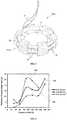
- Figures 1 and 2show an ocular implant 10a according to a first possible embodiment of the invention, which is designed to engage the capsular bag using photobonding.
- the ocular implant 10acomprises a deformable lens with a central optical portion 11 and a number of haptics 12a -six in this preferred embodiment-, which are uniformly distributed along an equatorial region of the central optical portion 11 of the lens.
- haptics 12aextend radially from the edge of the central optical portion 11, and comprise free ends in the shape of transverse curved plates in order to facilitate the transfer of the ciliary muscle forces to the lens.
- the haptics 12acontain a number of small microfluidic channels 13 through which a photosensitizer can flow from the lens or haptics towards an external convex surface 121a of the haptics 12a and a portion of the capsular bag that is to be in contact with the lens 10a, in order to stain them.
- the haptics 12aare made of a pHEMA-based polymer material and the photosensitizer applied through microfluidic channels 13 is Rose Bengal.
- the ocular implantfurther comprises a removable capsular tension ring 14.
- This tension ring 14is a cylindrical flexible body having a manipulation hole 141 at each of its ends.
- the tension ring 14is arranged in the internal concave portion 122a of some of the haptics 12a or all of them, and is used to stretch the ocular implant 10a so as to apply pressure to the haptics. This maximizes contact between the haptics 12a and the capsular bag.
- the removable capsular tension ring 14is attached to a probe 19 so that light can be transmitted through the probe and into the tension ring 14 so that it is capable of guiding light along the its entire length, and release the light required for photobonding in specific sites throughout its outer perimeter, including irradiating areas of the haptics 12a in contact with the capsular bag.
- the light usedhas a green wavelength.
- capsular tension ring 14is removable, but it is also possible that the tension ring is not removable but it can be deactivated once the light has been irradiated and the photobonding has been achieved.
- the capsular tension ring shown in Figures 1 and 2has two manipulation holes 141 at its ends. It is also possible that it has one or more manipulation hooks -not shown in the drawings- which are also valid for manipulating the ring.
- Figures 4 and 5show an ocular implant 10b according to second possible embodiment of the invention, which is designed to engage the capsular bag using photobonding.
- the ocular implant 10bconsists of a deformable lens with a central optical portion 11 with a number of haptics 12b -six in this preferred embodiment-, which are uniformly distributed along an equatorial region of the central optical portion 11 of the lens.
- the haptics 12b in this embodimentalso extend radially from the edge of the central optical portion 11, and comprise free ends in the shape of transverse curved plates in order to facilitate the transfer of the ciliary muscle forces to the lens.
- an external convex surface 121b of the haptics 12bis coated with a photosensitizer, which is shown as shaded in Fig. 4 .
- the haptics 12bare made of a poly-hydroxyethylmethacrylate (pHEMA)-based polymer material and the photosensitizer coating the external surface 121b of the haptics is Rose Bengal.
- pHEMApoly-hydroxyethylmethacrylate
- the ocular implantfurther comprises one or two removable torus-shaped inflatable balloons 15, similar to a balloon catheter, with embedded fiber optics 16 along the outer edge of the balloon 15.
- the balloonis transparent and that the fiber optics is embedded inside the balloon instead of being embedded or extending along the perimeter of the balloon.
- the one or two balloons 15are arranged in the internal concave portion 122b of the haptics 12b, and are used both to stretch the implantable device 10b so as to apply pressure to the haptics and to provide contact and light distribution as explained below.
- the inflation of the balloon or balloons 15is controlled externally by means of a cannula 17.
- the balloon 15stretches the implantable device 10b and presses its haptics 12b against the capsular bag, to provide close contact between the haptics 12b and the capsular bag needed for photobonding.
- the embedded fiber optics 16guides light injected by the cannula 17, and releases light throughout its perimeter, thereby irradiating areas of the haptics in contact with the capsular bag.
- the balloon 15contains micropores (not shown in the figures) that release air or oxygen during inflation, so as to facilitate the oxygen-requiring photochemical reaction.
- the balloons 15are de-inflated and removed after photobonding.
- the light guided into the fiber opticshas a green wavelength.
- the following exampleillustrates an experimental procedure followed for implanting a body made of a polymer material to the capsular bag by photobonding.
- Capsular bagswere obtained from freshly enucleated New Zealand albino rabbit eyes, less than 12 hours post-mortem.
- a circular section of the anterior capsule of the largest possible diameter (7-10 mm)was removed from the eye under an ophthalmological surgical microscope, using capsular scissors and immersed in a buffered saline solution BSS. strips of capsule (5x7-10 mm) were cut and reserved for testing in the buffered saline solution.
- the polymer material usedwas a copolymer of pHEMA and GMA, provided by Vista Optics Ltd under the commercial name of Vistaflex Advantage +49. Samples of the copolymer material were cut, using a precision optics diamond-fiber cutter into 5x10 mm rectangular strips, of 1 mm thickness. The water content of the material is 49% in a hydration state. Each piece was dehydrated and then rehydrated in a Rose Bengal 0.1 % solution.
- the Rose Bengal 0.1 % solutionwas prepared dissolving 0.01 g of commercial Rose Bengal sodium salt (provided by Sigma Aldrich) into 10 ml of a phosphate buffered solution (PBS).
- PBSphosphate buffered solution
- the custom-developed light delivery system used in this experimentconsisted of a pumped all-solid-state green laser source (provided by CNI Tech, Co. Ltd, China), with a central wavelength of 532 nm and an output power of 1300 mW and 1100 mW at the end of the fiber.
- the fiber tipis placed in the focal point of a 150-mm focal length lens.
- the sample holderis placed one focal length after the collimating lens.
- the light delivery systemhas neutral density filters which allow changing the laser power density at the sample plane between 0.65 and 0.25 W/cm 2 .
- Capsular bag stripswere stained in Rose Bengal by immersion in the Rose Bengal solution for 2 minutes. The capsular bag strips were placed and deployed on top of the pHEMA-GMA strips, so that about half of the capsular bag strip and polymer strip overlapped, and they were placed in the sample holder of the light delivery system. Exposure times ranged between 30 and 180 s, and laser irradiances between 0.25 and 0.65 W/cm 2 .
- the strength of the bondingwas tested using uniaxial extensiometry.
- the capsular bag end and the pHEMA endwere clamped in a custom-developed extensiometry system, provided with piezo-motors and load sensors.
- the different loadswere achieved by displacing each arm in 0.1 mm-steps, and the load producing a breakage in the capsule-pHEMA bonding was measured.
- Figure 6shows the loads that produced breakage of the capsule-pHEMA bonding as function of irradiation time, for three different laser irradiances: 0.25 W/cm 2 (curve 101), 0.45 W/cm 2 (curve 102) and 0.65 W/cm 2 (curve 103).
- the overlapped pHEMA/capsular bag areawas 21 mm 2 , on average.
- the average bonding resistance (load per bonded area)was 1 g/mm 2 .
- the experimentwas repeated for an irradiance of 0.45 W/cm 2 and exposure times between 60 and 180 s in a nitrogen environment, by placing the capsular bag-polymer strip system in a chamber connected to a nitrogen pump.
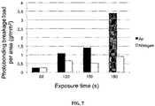
- Figure 7shows the loads per photobonded area that produced breakage of the capsule-pHEMA bonding in air and in a nitrogen environment, for irradiance of 0.45 W/cm 2 and different exposure times.
- the stress valuesare normalized by the photobonded area, which was on average 15.41 ⁇ 4.54 mm 2 in the experiments in air, and 18.86 ⁇ 5.26 mm 2 in the experiments in nitrogen.
- photobondingwas significantly weaker in the nitrogen environment. For example, for a exposure time of 120 s breakage of the photobonding occurred for a stress per area 1.63 times higher in air than in hydrogen environment. Capsular breakage occurred in air for the longer exposure time.
- an intraocular lenswas bonded to a capsular bag by means of photochemically-induced bonding.
- This exampleillustrates the bonding of the haptics of a pHEMA-MMA intraocular lens to the anterior lens capsule, intraocularly, demonstrating the feasibility of the procedure intraocularly.
- Enucleated rabbit eyeswere obtained less than 4 hours post-mortem.
- the corneawas cut, and the crystalline lens material was aspirated using a Simcoe cannula through a 5-mm diameter anterior lens capsulorhexis.
- a 2-plate haptic pHEMA-MMA Akreos lens(by Bausch and Lomb®) was stained in a 0.1% Rose Bengal solution during 2 minutes, and then inserted in the capsular bag.
- An air bubble (1 ml approximately)was infused in the vitreous cavity of the eye using a 25-gauge needle. The air bubble created pressure between the capsular bag inner wall and the IOL and haptic plates.
- the whole eyewas immersed in saline solution in a cuvette and the cuvette placed under the light delivery system.
- the cuvettewas shifted laterally, such that the optical axis of the instrument was 2-mm-off centered from the IOL apex.
- the estimated peak irradiancewas 0.25 W/cm 2 at the location of one haptic and 0.05 W/cm 2 at the location of the second haptic.
- Exposure timewas 300 s.
- the IOLwas cut in two pieces inside the capsular bag. Strong bonding was achieved between the anterior capsular bag the haptic of the lens that had been exposed to the higher irradiance, while no bonding was achieved between for the haptic of the lens that had been exposed to the lower irradiance.
- the IOL implantationwas done under similar conditions, but in this case the capsular bag was stained with a solution of 0.1% Rose Bengal using 30 gauge cannula during the hydro-dissection maneuver (injection of rose Bengal in the plane between the capsular bag and the lens cortex) after performing the anterior capsulorhexis.
- the IOLwas then implanted through the capsulorhexis into the capsular bag.
- the IOLwas cut in two pieces inside the capsular bag. Strong bonding was achieved between the anterior capsular bag and the haptic of the lens that had been exposed to the higher irradiance, while no bonding was achieved between for the haptic of the lens that had been exposed to the lower irradiance.
- the cornea and the iriswere removed, and a scleral window was performed to expose the lens equator. Then the capsular bag was emptied through a 6-mm diameter capsulorhexis and the capsule was stained with Rose Bengal during the hydro-dissection maneuver. Then a piece of pHEMA re-hydrated in Rose Bengal was introduced through the rhexis and placed against the equator with a forceps. In that position irradiation was performed through the scleral window (0.65 mW/cm 2 , 150 s). Then a silicone tube was glued to the pHEMA piece with cyanoacrylate.
Landscapes
- Health & Medical Sciences (AREA)
- Ophthalmology & Optometry (AREA)
- Animal Behavior & Ethology (AREA)
- General Health & Medical Sciences (AREA)
- Veterinary Medicine (AREA)
- Engineering & Computer Science (AREA)
- Biomedical Technology (AREA)
- Heart & Thoracic Surgery (AREA)
- Vascular Medicine (AREA)
- Life Sciences & Earth Sciences (AREA)
- Public Health (AREA)
- Oral & Maxillofacial Surgery (AREA)
- Cardiology (AREA)
- Transplantation (AREA)
- Physics & Mathematics (AREA)
- Electromagnetism (AREA)
- Optics & Photonics (AREA)
- Nuclear Medicine, Radiotherapy & Molecular Imaging (AREA)
- Surgery (AREA)
- Prostheses (AREA)
Description
- The present invention relates to ophthalmic implants and related methods, and more particularly to intraocular lenses, including those aiming at restoring accommodation.
- The optical system of the eye is composed by refractive elements (cornea and lens) and aqueous and vitreous humors. The crystalline lens of the eye is the second lens in the eye, behind the cornea and the iris. In the emmetropic eye the optical power of the cornea and crystalline lens are such that the optical image is projected sharply on the retina. In the young eye the crystalline lens can alter its shape to accommodate near and far objects. This capability is lost with age (a condition called presbyopia). Also, the normal lens is transparent. Also with aging, the crystalline lens opacifies (a condition called cataract).
- The crystalline lens can be replaced by an artificial intraocular lens (IOL) to correct for refractive errors in non-emmetropic eyes, and more commonly, to correct for cataract. Recently, intraocular lenses that aim at restoring the accommodation capability of the eye (i.e. correcting presbyopia) have been proposed. These accommodating IOLs (A-IOLs) are intended to use of the accommodative forces transmitted from the ciliary muscle to the lens by the zonulae and the lens capsule, to shift axially or laterally one of more elements, or reshape the geometry of the lens.
- Most intraocular lens designs have a central optical zone and two or more haptics to hold the lens in place inside the capsular bag, and to guarantee IOL stability and centration. While intracapsular cataract surgery has proved safe and in most cases uneventful, postoperative problems may arise associated to capsular fibrosis that results from anterior capsule epithelial cells proliferation and migration. Capsular fibrosis may result in posterior capsule opacification (and the need of a secondary surgery) and capsular bag contraction and IOL misalignment.
- An alternative IOL design aimed at preventing the effects of capsular fibrosis and opacification is that of the so-called "bag in the lens". In this technique the peripheral groove of the lens allows holding the anterior and posterior capsulorhexis (surgically performed window edges) of the capsular bag.
- Haptic design is of particular relevance in A-IOLs, as they require the transmission of forces from the accommodative implant into the lens. The mechanism of operation of several accommodating IOL designs requires the capsular bag to operate similarly to that in the intact eye, although it is likely that fibrosis following cataract surgery will compromise these mechanisms.
- An identified problem of several accommodating IOLs is the lack of a strong connection with the capsular bag that is needed for adequate transfer of forces from the ciliary muscle to the action mechanism of the lens; this is the case of the two optic accommodative lens system disclosed in patent document
US-7150760 . - Some A-IOLs require that the connection between the haptics and the periphery of the capsular bag is produced by natural fibrosis occurring during the weeks following implantation. However, this uncontrolled process may result in a limitation of the shifting or reshaping mechanism of the A-IOL.
- Some patent documents disclose haptic devices that depend on the fibrosis process, such as
US-6193750 .US-2011/0307058 proposes the zonular capture haptic, which favors the fusion of the capsular bag to the haptics, assisted by the natural process of fibrosis. This approach requires two surgical acts separated by days, in which the haptic platform and the A-IOL are implanted, respectively. Relying on the natural fibrosis for the engaging the A-IOL to the capsular bag has several drawbacks, including the duration of the process, uncertainty in the A-IOL alignment, and the final outcome of the engagement. Nevertheless, engagement of the haptic to the capsule is critical in several A-IOL designs: - Patent document
US-2003/0204254 proposes mechanical engagement of the lens haptic (or lens periphery) to the edge of the capsulorhexis using mechanical blocking arms or clasps. A drawback of such a mechanical attachment to the capsule is the potential tearing or rupture of the capsule. - An alternative to the use of mechanical capsule-IOL engagement system is the use of bio-adhesives. Bio-adhesive materials are increasingly used in medicine for tissue repair in surgery, drug delivery, or attachment of prosthetic devices. For example, patent document
US-2008/0140192 discloses the use of a reversible thermo-responsive adhesive substance for attaching microelectronic retinal implants to the retinal tissue. This particular polymer has the property of becoming adhesive to cells above a critical temperature, 32º, in aqueous environments. - The use of bio-adhesive polymers has been recognized as advantageous in applications where an intraocular lens requires a firm attachment to the capsular bag to transmit the forces of the accommodative plant into an A-IOL mechanism. Patent document
WO-96/35398 - Patent document
US-2011/0029074 proposes the use of a thermo-reversible material for applications in intraocular surgery, including A-IOL implantation and stunt implantation in glaucoma. In this document they also recognize the need for effectively translating the ocular forces of the natural accommodative mechanism to maximize the accommodation amplitude of A-IOLs, and propose the use of polymeric systems that may modify their adhesive properties in response to changes of the physical and chemical characteristics of the physiological medium. In particular, they propose the use of a thermo-reversible adhesive polymer coating the surface of certain areas of a haptic structure (and possibly the surface of the IOL) to favor the adhesion of the system to the capsular bag. The thermo-adhesive polymer would exhibit adhesive properties at body temperature. Irrigation with cold or room temperature solution during the surgical procedure, or possibly for explantation could produce detachment of the IOL/haptic from the capsular bag. Although pNIPAM polymer is described as a biocompatible non-toxic substance to neural tissue or cultured cells, its intraocular non-toxicity has never been proven. The non-polymerized form NIPAM has been proven toxic to neural tissue. On the other hand, the dynamical properties of the pNIPAM adhesive when deposited as a thin layer across the capsulorhexis have not been proven and it is not clear whether it may remain for sufficient time to produce a thermo-adhesive response. - The use of photo-chemically induced bonding processes is also known. The use of localized light delivery is particularly well suited intraocularly, as done in several procedures, including retinal photocoagulation or laser trabeculoplasty in glaucoma. The use of localized irradiation in internal body organs is generally performed by the use of catheters for visualization, sensing or treatment. For example, as described in patent document
US-6106550 , light can be conducted through a fiber and emitted from its end into the surroundings for purposes of, among others, illumination or for cutting tissue with a laser beam. - Also, a photo-activated process is used in corneal collagen cross-linking for the treatment of keratoconus by tissue stiffening. In this procedure, formation of inter- and intra-fibrillar bonding is produced by the instillation of a photosensitizer (typically a riboflavin-containing solution) and irradiation with UVA light. Corneal collagen photo-cross-linking has also been demonstrated with other photosensitizers, such as Rose Bengal, and irradiation with green light. One of the advantages of the use of Rose Bengal is that it is an FDA-approved compound of widespread use in ophthalmology, for example in dry eye staining tests. In addition, intracapsular use of Rose Bengal has proved non-toxic in rabbit eye models. The use of photosensitizers and photo-activation is described in
US-7331350 to produce heat-free bonding of damaged tissue for repair, therefore replacing sutures of staples. These photochemical tissue-bonding methods include the application of a photosensitizer to tissue (i.e. the cornea) followed by irradiation with electromagnetic energy to produce a tissue-tissue seal, in the absence of an exogeneously supplied source of cross-linkable structure. It is thought that in photochemical bonding that activation of the photo-initiator by light absorption produces structural changes in the amino acids of the proteins of the tissue and formation of covalent bonds between collagen molecules on opposing surfaces of the two tissues in contact. - Document
WO2011031557 discloses an ocular implant comprising an optical portion and two haptics wherein a photoactivated adherent is disposed on the surface of the haptics. Therefore, there is a need for an accommodating intraocular lens that can be securely fixed to the capsular eye by means of a non-toxic process and, at the same time, providing sufficient resistance to rupture. - Insofar as the terms "invention" and/or "embodiment" are used in the following, and/or features are presented as being optional, this should be interpreted in such a way that the only protection sought is that of the invention as claimed. In the present invention, the use of a photochemically induced bonding is proposed in situations requiring intraocular engagement of a polymer implant to ocular tissue, such as the implanation of an intraocular lens in the eye, such as in cataract surgery, or in spresbyopia or refractive surgery with intraocular lens implants.
- The present invention is mainly based on the fact that intraocular tissue bonds tightly to a polymer material, such as pHEMA, upon the application of a photosensitizer and irradiation with light. In the present invention the attachment to tissue of an implant having at least a polymeric portion that will come into contact with the tissue is performed by applying a photosensitizer in a portion of the tissue and/or a portion of the implant and then by irradiating with light, in the absence of any exogenously supplied source of cross-linkable substrate, tissue adhesive or glue.
- The tissue and implant to be bonded are placed in close contact, during which time light irradiation is applied to produce photochemical engagement of the tissue and the implant. The inventors have proven that tight bonding occurs even in the absence of collagen or proteins in the material.
- The photochemical bonding between tissue and a polymer material according to the present invention is particularly useful and specially advantageous with accommodating IOLs, where it is necessary that the forces from the ciliary body are directly transmitted to the mechanism of the accommodating IOL (AIOL) to alter the shape of a deformable element, or to change the axial position of one or more elements of the lens. This direct transmission of the forces of the ciliary body and the implant IOL is achieved by means of the resulting photobonded portions.
- A first aspect of the invention relates to an ocular implant, which comprises:
- an optical portion; and,
- at least two polymer haptics for fixation of the ocular implant to tissue inside an eye;
- That is, the ocular implant comprises two or more polymer haptics, and at least one portion of each haptic -which will come into contact with the eye tissue- contains a photoinitiating agent (it is made of or coated with, a material containing a photoinitiating agent), so that that portion of the haptics is, per se, capable of providing the photoinitiating agent. Or the at least one portion of the haptics which is appropriate for contacting the eye tissue is provided with means for delivering the photoinitiating agent, which may be kept in some sort of deposit or enclosure embedded within the haptics, or in a container or source external to the haptics; such delivery means can comprise multiple microfluidic channels or a membrane, through which the photoinitiating agent can flow and be delivered at an outer surface of the haptics.
- In particular, the present invention describes a haptic structure which is photochemically-bonded to the capsular bag to engage the mechanical forces of the accommodative mechanism in an A-IOL to restore accommodation.
- By ocular implant it is meant an artificial functional implantable device that restores a function that is compromised or lost in the eye. Preferably, the ocular implant is an intraocular lens, and more preferably an accommodating IOL.
- The at least two haptics of the implantable device are polymer haptics, that is, they are made of a polymer material, or they are coated with a polymer material, or they have a portion made of a polymer material.
- By polymer material it is understood any suitable biocompatible polymer, and more preferably HEMA derivatives such as pHEMA, pHEMA-MMA, pHEMA-GMA, etc.
- By photoinitiating agent or photoinitiator is understood is any chemical compound that generates free radicals or other reactive chemical species from components in the tissue when exposed to light.
- The optical portion of the ocular implant is preferably able to change its optical power in response to a force applied thereto.
- In a preferred embodiment, the photoinitiating agent delivery means comprises an outer surface of the haptics being coated with the photoinitiating agent or such outer surface comprising an outer layer of the haptics where the photoinitiating agent is embedded.
- In this preferred embodiment, the ocular implant may be introduced in an eye where the polymer haptics are deployed and spread out inside the eye, causing the haptics, which outer surfaces are impregnated with the photoinitiating agent or have the photoinitiating agent embedded in the outer surface, to contact with the capsular bag. By irradiating that contact portion with an external or internal light source the photochemical bond in the contact portion between the polymer haptics and the eye tissue is produced.
- In another preferred embodiment the photoinitiating agent delivery means comprises multiple microfluidic channels through which the photoinitiating agent can flow, such microfluidic channels being arranged such that the photoinitiating agent is delivered in an outer surface of the haptics. The photoinitiating agent can be contained in a reservoir provided in the ocular implant or it can be injected from an external reservoir through the microfluidic channels.
- In a preferred embodiment the ocular implant further comprises means for making the implant to be in a stretched state; in such a state the haptics better contact the capsular bag.
- This means for making the implant to be in a stretched state may comprise at least one tension ring, such as a capsular tension ring.
- In another preferred embodiment, the means for making the implant to be in a stretched state may comprise at least one balloon.
- The means for making the implant to be in a stretched state are preferably located with respect to the haptics such that it transmits a centrifugal force to the haptics. For instance, the haptics may comprise curved plates, and the tension ring or the balloon are located in an inner surface of the plates, such that when the tension ring is tensioned or the balloon inflated the haptics are pushed outwards in a radial direction.
- As outlined above, the ocular implant of the present invention may further comprise light guiding elements.
- In a preferred embodiment, these light guiding elements can be embedded or be part of the means for making the implant to be in a stretched state. For instance, the light guiding elements can be embedded in the outer perimeter of the tension ring or the balloon.
- The means for making the implant to be in a stretched state can be removable or deactivatable, such that once the light has been irradiated the means can be removed or deactivated.
- Since the ocular implant is to be used in a human body, it should be safely preserved from being infected or contaminated till the implantation. Therefore, the ocular implant of the present invention may be additionally coated or embedded in a preserving composition in order to guarantee the correct storing and optimal state for implantation. The preserving solution can protect the ocular implant from external infection or contamination and it can function not to cause endophthalmitis during implantation into the human body. The composition for preserving an artificial intraocular lens of the invention may comprise a wetting agent, an antimicrobial agent, a stabilizer, an isotonic agent, a solubilizing aid, a viscosity adjuster, an antioxidant or a buffering solution. Thus, in a preferred embodiment, the ocular implant as described in the present invention is coated or embedded in a preserving composition, more preferably this preserving composition comprises a wetting agent, an antimicrobial agent, a stabilizer, an isotonic agent, a solubilizing aid, a viscosity adjuster, an antioxidant and/or a buffering solution.
- A second aspect of the invention relates to a kit for implanting an ocular implant in an eye, the kit comprises:
- the ocular implant to be implanted comprising at least two polymer haptics;
- a photoinitiating agent for at least partially impregnating a first portion of the ocular implant and/or a second portion of tissue in the eye; and,
- a light source for providing light of a wavelength adapted to excite the photoinitiating agent.
- The ocular implant in the kit is preferably in accordance with the ocular implant defined hereinbefore.
- As indicated before, the photoinitiator or photoinitiating agent is any chemical compound that absorbs the energy of light when exposed to it, the light preferably being ultraviolet, visible or near infrared radiation. Examples of photoinitiators include various light-sensitive dyes and biological molecules such as, for example, Rose Bengal, riboflavin, eosin Y, methylene blue, porphyrins, thioxanthenes, bacteriochloropylls, phenothiazines, cyanines, quinones and photosensitive derivatives thereof.
- In a preferred embodiment the photoinitiating agent is a solution containing Rose Bengal, and it is photoactivated with a light source providing light having green wavelengths. In another embodiment the photoinitiating agent is a solution containing Riboflavin, photoactivated with a light source providing light having UV wavelengths. In other embodiments the photoinitiating agent is another photoactivable component, activated at another particular wavelength of light.
- A further aspect of the invention refers to a method for implanting an ocular implant inside an eye, the method comprising the following steps:
- i) introducing the ocular implant inside the eye, wherein a first portion of the ocular implant and/or a second portion of tissue in the eye contains a photoinitiating agent in their surface; and
- ii) irradiating said first portion and/or said second portion with light when there is contact between the first portion of the ocular implant and the eye tissue or between the ocular implant and the second portion of the eye tissue; such that the ocular implant is photochemically bonded to the eye.
- Another aspect of the invention refers to a method for implanting an ocular implant inside an eye, the method comprising the following steps:
- i) impregnating a first portion of the ocular implant or a second portion of the eye tissue with a photoinitiating agent or both;
- ii) introducing the ocular implant inside the eye; and,
- iii) irradiating said first portion and/or said second portion with light when there is contact between the first portion of the ocular implant and the eye tissue or between the ocular implant and the second portion of the eye tissue;
- In either method, light is irradiated preferably for a duration less than 600 s, and more preferably for less than 180 s.
- The step of irradiating with light is preferably carried out at irradiance below 0.65 W/cm2.
- The ocular implant used in either method is preferably in accordance with the ocular implant defined hereinbefore.
- In a further aspect of the invention an ocular implant is defined, which comprises:
- an optical portion; and,
- at least two polymer haptics;
- at least one fixing portion for affixing the ocular implant to tissue inside an eye, the fixing portion being generated by photochemically inducing a bond on an overlapping area between the haptics and the eye tissue.
- The different aspects and embodiments of the invention defined in the foregoing can be combined with one another, as long as they are compatible with each other.
- Additional advantages and features of the invention will become apparent from the detail description that follows and will be particularly pointed out in the appended claims.
- To complete the description and in order to provide for a better understanding of the invention, a set of drawings is provided. Said drawings form an integral part of the description and illustrate an embodiment of the invention, which should not be interpreted as restricting the scope of the invention, but just as an example of how the invention can be carried out. The drawings comprise the following figures:
Figure 1 shows a cross-section view of an intraocular lens according to a first possible embodiment of the invention.Figure 2 shows a perspective view of the intraocular lens ofFigure 1 .Figure 3 shows an embodiment of the removable capsular tension ring.Figure 4 shows a section view of an intraocular lens according to a second possible embodiment of the invention.Figure 5 shows a perspective view of the intraocular lens ofFigure 3 .Figure 6 is a diagram showing the influence of the radiation exposure times and irradiance on the strength of the bond between the ocular implant and the capsular bag.Figure 7 is a diagram showing the loads per photobonded area that produced breakage of the capsule-pHEMA bonding in air and in a nitrogen environment.- The following description is not to be taken in a limiting sense but is given solely for the purpose of describing the broad principles of the invention. Next embodiments of the invention will be described by way of example, with reference to the above-mentioned drawings.
Figures 1 and 2 show anocular implant 10a according to a first possible embodiment of the invention, which is designed to engage the capsular bag using photobonding.- The
ocular implant 10a comprises a deformable lens with a centraloptical portion 11 and a number ofhaptics 12a -six in this preferred embodiment-, which are uniformly distributed along an equatorial region of the centraloptical portion 11 of the lens. Thesehaptics 12a extend radially from the edge of the centraloptical portion 11, and comprise free ends in the shape of transverse curved plates in order to facilitate the transfer of the ciliary muscle forces to the lens. - In this first preferred embodiment, the
haptics 12a contain a number of smallmicrofluidic channels 13 through which a photosensitizer can flow from the lens or haptics towards an externalconvex surface 121a of thehaptics 12a and a portion of the capsular bag that is to be in contact with thelens 10a, in order to stain them. - The
haptics 12a are made of a pHEMA-based polymer material and the photosensitizer applied throughmicrofluidic channels 13 is Rose Bengal. - The ocular implant further comprises a removable
capsular tension ring 14. Thistension ring 14 is a cylindrical flexible body having amanipulation hole 141 at each of its ends. Thetension ring 14 is arranged in the internalconcave portion 122a of some of thehaptics 12a or all of them, and is used to stretch theocular implant 10a so as to apply pressure to the haptics. This maximizes contact between thehaptics 12a and the capsular bag. - Additionally, and as shown in detail in
Figure 3 , the removablecapsular tension ring 14 is attached to aprobe 19 so that light can be transmitted through the probe and into thetension ring 14 so that it is capable of guiding light along the its entire length, and release the light required for photobonding in specific sites throughout its outer perimeter, including irradiating areas of thehaptics 12a in contact with the capsular bag. In this preferred embodiment the light used has a green wavelength. - In the case shown in the drawings the
capsular tension ring 14 is removable, but it is also possible that the tension ring is not removable but it can be deactivated once the light has been irradiated and the photobonding has been achieved. - The capsular tension ring shown in
Figures 1 and 2 has twomanipulation holes 141 at its ends. It is also possible that it has one or more manipulation hooks -not shown in the drawings- which are also valid for manipulating the ring. Figures 4 and5 show anocular implant 10b according to second possible embodiment of the invention, which is designed to engage the capsular bag using photobonding.- The
ocular implant 10b consists of a deformable lens with a centraloptical portion 11 with a number ofhaptics 12b -six in this preferred embodiment-, which are uniformly distributed along an equatorial region of the centraloptical portion 11 of the lens. The haptics 12b in this embodiment also extend radially from the edge of the centraloptical portion 11, and comprise free ends in the shape of transverse curved plates in order to facilitate the transfer of the ciliary muscle forces to the lens. - In this case, an external
convex surface 121b of thehaptics 12b is coated with a photosensitizer, which is shown as shaded inFig. 4 . - The haptics 12b are made of a poly-hydroxyethylmethacrylate (pHEMA)-based polymer material and the photosensitizer coating the
external surface 121b of the haptics is Rose Bengal. - The ocular implant further comprises one or two removable torus-shaped
inflatable balloons 15, similar to a balloon catheter, with embeddedfiber optics 16 along the outer edge of theballoon 15. Although not shown in the drawings, it is possible that the balloon is transparent and that the fiber optics is embedded inside the balloon instead of being embedded or extending along the perimeter of the balloon. - The one or two
balloons 15 are arranged in the internalconcave portion 122b of thehaptics 12b, and are used both to stretch theimplantable device 10b so as to apply pressure to the haptics and to provide contact and light distribution as explained below. - The inflation of the balloon or balloons 15 is controlled externally by means of a
cannula 17. Upon inflation, theballoon 15 stretches theimplantable device 10b and presses itshaptics 12b against the capsular bag, to provide close contact between the haptics 12b and the capsular bag needed for photobonding. - The embedded
fiber optics 16 guides light injected by thecannula 17, and releases light throughout its perimeter, thereby irradiating areas of the haptics in contact with the capsular bag. - In a preferred embodiment of this
ocular implant 10b, theballoon 15 contains micropores (not shown in the figures) that release air or oxygen during inflation, so as to facilitate the oxygen-requiring photochemical reaction. - In either case, the
balloons 15 are de-inflated and removed after photobonding. The light guided into the fiber optics has a green wavelength. - The following example illustrates an experimental procedure followed for implanting a body made of a polymer material to the capsular bag by photobonding.
- Capsular bags were obtained from freshly enucleated New Zealand albino rabbit eyes, less than 12 hours post-mortem. A circular section of the anterior capsule of the largest possible diameter (7-10 mm) was removed from the eye under an ophthalmological surgical microscope, using capsular scissors and immersed in a buffered saline solution BSS. Strips of capsule (5x7-10 mm) were cut and reserved for testing in the buffered saline solution.
- The polymer material used was a copolymer of pHEMA and GMA, provided by Vista Optics Ltd under the commercial name of Vistaflex Advantage +49. Samples of the copolymer material were cut, using a precision optics diamond-fiber cutter into 5x10 mm rectangular strips, of 1 mm thickness. The water content of the material is 49% in a hydration state. Each piece was dehydrated and then rehydrated in a Rose Bengal 0.1 % solution.
- The Rose Bengal 0.1 % solution was prepared dissolving 0.01 g of commercial Rose Bengal sodium salt (provided by Sigma Aldrich) into 10 ml of a phosphate buffered solution (PBS).
- The custom-developed light delivery system used in this experiment consisted of a pumped all-solid-state green laser source (provided by CNI Tech, Co. Ltd, China), with a central wavelength of 532 nm and an output power of 1300 mW and 1100 mW at the end of the fiber. The fiber tip is placed in the focal point of a 150-mm focal length lens. The sample holder is placed one focal length after the collimating lens. The light delivery system has neutral density filters which allow changing the laser power density at the sample plane between 0.65 and 0.25 W/cm2.
- Capsular bag strips were stained in Rose Bengal by immersion in the Rose Bengal solution for 2 minutes. The capsular bag strips were placed and deployed on top of the pHEMA-GMA strips, so that about half of the capsular bag strip and polymer strip overlapped, and they were placed in the sample holder of the light delivery system. Exposure times ranged between 30 and 180 s, and laser irradiances between 0.25 and 0.65 W/cm2.
- The strength of the bonding was tested using uniaxial extensiometry. For this testing the capsular bag end and the pHEMA end were clamped in a custom-developed extensiometry system, provided with piezo-motors and load sensors. The different loads were achieved by displacing each arm in 0.1 mm-steps, and the load producing a breakage in the capsule-pHEMA bonding was measured.
Figure 6 shows the loads that produced breakage of the capsule-pHEMA bonding as function of irradiation time, for three different laser irradiances: 0.25 W/cm2 (curve 101), 0.45 W/cm2 (curve 102) and 0.65 W/cm2 (curve 103).- As can be seen, increasing exposure time and laser irradiance levels increases the breakage point of the bond created. Exposure times higher than 90 s at all tested laser irradiance levels produced a secure bonding, since photobonding breakage occurs for loads significantly higher (more than a factor 5 in the experiments carried out) than the cilliary muscle forces acting on the lens zonulae and capsular bag in human eyes.
- The overlapped pHEMA/capsular bag area was 21 mm2, on average.
- The average bonding resistance (load per bonded area) was 1 g/mm2.
- At higher irradiances (0.65 W/cm2) photobonding breakage was never observed for exposure times higher than 30 s. Instead, for this irradiance the rupture was produced in the capsular bag, suggesting that the photobonding may introduce structural changes in the capsular bag, making it more brittle. Capsular bag breakage occurred at much higher loads (55 g for 0.65 W/cm2, 180 s exposure time) in tissue from pigmented rabbits than from New Zealand albino rabbits.
- The experiment was repeated for an irradiance of 0.45 W/cm2 and exposure times between 60 and 180 s in a nitrogen environment, by placing the capsular bag-polymer strip system in a chamber connected to a nitrogen pump.
Figure 7 shows the loads per photobonded area that produced breakage of the capsule-pHEMA bonding in air and in a nitrogen environment, for irradiance of 0.45 W/cm2 and different exposure times. For a direct comparison with the photobonding in air, the stress values are normalized by the photobonded area, which was on average 15.41 ± 4.54 mm2 in the experiments in air, and 18.86 ± 5.26 mm2 in the experiments in nitrogen. For all the exposure conditions, photobonding was significantly weaker in the nitrogen environment. For example, for a exposure time of 120 s breakage of the photobonding occurred for a stress per area 1.63 times higher in air than in hydrogen environment. Capsular breakage occurred in air for the longer exposure time. These results indicate that the presence of oxygen facilitates the photochemical processes involved in the capsular bag-polymer bonding.- In another example an intraocular lens was bonded to a capsular bag by means of photochemically-induced bonding.
- This example illustrates the bonding of the haptics of a pHEMA-MMA intraocular lens to the anterior lens capsule, intraocularly, demonstrating the feasibility of the procedure intraocularly.
- Enucleated rabbit eyes were obtained less than 4 hours post-mortem. The cornea was cut, and the crystalline lens material was aspirated using a Simcoe cannula through a 5-mm diameter anterior lens capsulorhexis. A 2-plate haptic pHEMA-MMA Akreos lens (by Bausch and Lomb®) was stained in a 0.1% Rose Bengal solution during 2 minutes, and then inserted in the capsular bag. An air bubble (1 ml approximately) was infused in the vitreous cavity of the eye using a 25-gauge needle. The air bubble created pressure between the capsular bag inner wall and the IOL and haptic plates. The whole eye was immersed in saline solution in a cuvette and the cuvette placed under the light delivery system. The cuvette was shifted laterally, such that the optical axis of the instrument was 2-mm-off centered from the IOL apex. The estimated peak irradiance was 0.25 W/cm2 at the location of one haptic and 0.05 W/cm2 at the location of the second haptic. Exposure time was 300 s.
- After exposure the IOL was cut in two pieces inside the capsular bag. Strong bonding was achieved between the anterior capsular bag the haptic of the lens that had been exposed to the higher irradiance, while no bonding was achieved between for the haptic of the lens that had been exposed to the lower irradiance.
- In an additional procedure in a different eye, the IOL implantation was done under similar conditions, but in this case the capsular bag was stained with a solution of 0.1% Rose Bengal using 30 gauge cannula during the hydro-dissection maneuver (injection of rose Bengal in the plane between the capsular bag and the lens cortex) after performing the anterior capsulorhexis. The IOL was then implanted through the capsulorhexis into the capsular bag. As in the former procedure, after exposure the IOL was cut in two pieces inside the capsular bag. Strong bonding was achieved between the anterior capsular bag and the haptic of the lens that had been exposed to the higher irradiance, while no bonding was achieved between for the haptic of the lens that had been exposed to the lower irradiance.
- In another setting the cornea and the iris were removed, and a scleral window was performed to expose the lens equator. Then the capsular bag was emptied through a 6-mm diameter capsulorhexis and the capsule was stained with Rose Bengal during the hydro-dissection maneuver. Then a piece of pHEMA re-hydrated in Rose Bengal was introduced through the rhexis and placed against the equator with a forceps. In that position irradiation was performed through the scleral window (0.65 mW/cm2, 150 s). Then a silicone tube was glued to the pHEMA piece with cyanoacrylate. To evaluate the strength of the photobonding the sclera and the silicone tube were clamped to the two arms of the stretcher. Strong photobonding was obtained, with capsular breakage occurring while capsular bag-pHEMA was still bonded. The estimated bonding resistance was 0.85 g/mm2.
- In this text, the term "comprises" and its derivations (such as "comprising", etc.) should not be understood in an excluding sense, that is, these terms should not be interpreted as excluding the possibility that what is described and defined may include further elements, steps, etc.
- On the other hand, the invention is obviously not limited to the specific embodiment(s) described herein, but also encompasses any variations that may be considered by any person skilled in the art (for example, as regards the choice of materials, dimensions, components, configuration, etc.), within the general scope of the invention as defined in the claims.
Claims (13)
- An ocular implant (10a,10b), which comprises:- an optical portion (11); and,- at least two polymer haptics (12a, 12b) for fixation of the ocular implant (10a, 10b) to tissue inside an eye;characterised in that:- at least one portion of the haptics (12a, 12b) contains a photoinitiating agent delivery means for providing a photoinitiating agent activatable by light for creating a photochemical bond between the polymer haptic (12a, 12b) and the tissue inside the eye.
- The ocular implant (10a,10b) of claim 1, wherein the photoinitiating agent delivery means comprises an outer surface (121b) of the haptics (12b) being coated with the photoinitiating agent.
- The ocular implant (10a,10b) of claim 1, wherein the photoinitiating agent delivery means comprise an outer layer of the haptics where the photoinitiating agent is embedded.
- The ocular implant (10a,10b) of claim 1, wherein the photoinitiating agent delivery means comprises multiple microfluidic channels (13) through which the photoinitiating agent can flow for delivering the photoinitiating agent in an outer surface (121a) of the haptics (12a).
- The ocular implant (10a,10b) of any of claims 1-4, which further comprises means for making the implant to be in a stretched state.
- The ocular implant (10a,10b) of claim 5, wherein the means for making the implant to be in a stretched state comprises at least one tension ring (14).
- The ocular implant (10a,10b) of claim 5, wherein the means for making the implant to be in a stretched state comprises at least one balloon (15).
- The ocular implant (10a,10b) of any of claims 1-7, which further comprises light guiding elements (16).
- The ocular implant (10a, 10b) of claim 8 when dependent upon claims 6 or 7, wherein the light guiding elements (16) are embedded in the tension ring (14) or the balloon (15).
- A kit for implanting an ocular implant (10a, 10b) in an eye, the kit comprising:- the ocular implant (10a, 10b) comprising at least two polymer haptics;- a photoinitiating agent for at least partially impregnating a first portion of the ocular implant (10a, 10b) or a second portion of tissue in the eye;- a light source for providing light of a wavelength adapted to excite the photoinitiating agent.
- A kit according to claim 10, wherein the ocular implant is according to any of claims 1-9.
- A kit according to any of claims 10-11, wherein the photoinitiating agent is a solution containing riboflavin or Rose Bengal and the light source provides light having UV, blue and/or green wavelength.
- The ocular implant (10a,10b) of any of claims 1-4, which further comprises:- at least one fixing portion for affixing the ocular implant (10a, 10b) to the tissue inside the eye, the fixing portion being generated by photochemically inducing a bond on an overlapping area between the at least one portion of the haptics (12a, 12b) containing the photoinitiating agent activatable by light and the eye tissue.
Priority Applications (8)
| Application Number | Priority Date | Filing Date | Title |
|---|---|---|---|
| ES15382106.1TES2686472T3 (en) | 2015-03-10 | 2015-03-10 | Photochemically induced coupling of intraocular implants |
| EP15382106.1AEP3067015B1 (en) | 2015-03-10 | 2015-03-10 | Photochemically induced engagement of intraocular implants |
| US15/556,861US10383721B2 (en) | 2015-03-10 | 2016-03-10 | Photochemically induced engagement of intraocular implants |
| CN201680021798.5ACN107949355B (en) | 2015-03-10 | 2016-03-10 | Photochemically induced coaptation of intraocular implants |
| JP2017547969AJP6817216B2 (en) | 2015-03-10 | 2016-03-10 | Photochemically evoked engagement of intraocular implants |
| EP16709422.6AEP3267944A1 (en) | 2015-03-10 | 2016-03-10 | Photochemically induced engagement of intraocular implants |
| PCT/EP2016/055191WO2016142490A1 (en) | 2015-03-10 | 2016-03-10 | Photochemically induced engagement of intraocular implants |
| US16/537,081US11291537B2 (en) | 2015-03-10 | 2019-08-09 | Photochemically induced engagement of intraocular implants |
Applications Claiming Priority (1)
| Application Number | Priority Date | Filing Date | Title |
|---|---|---|---|
| EP15382106.1AEP3067015B1 (en) | 2015-03-10 | 2015-03-10 | Photochemically induced engagement of intraocular implants |
Publications (2)
| Publication Number | Publication Date |
|---|---|
| EP3067015A1 EP3067015A1 (en) | 2016-09-14 |
| EP3067015B1true EP3067015B1 (en) | 2018-06-06 |
Family
ID=52648969
Family Applications (2)
| Application Number | Title | Priority Date | Filing Date |
|---|---|---|---|
| EP15382106.1AActiveEP3067015B1 (en) | 2015-03-10 | 2015-03-10 | Photochemically induced engagement of intraocular implants |
| EP16709422.6AWithdrawnEP3267944A1 (en) | 2015-03-10 | 2016-03-10 | Photochemically induced engagement of intraocular implants |
Family Applications After (1)
| Application Number | Title | Priority Date | Filing Date |
|---|---|---|---|
| EP16709422.6AWithdrawnEP3267944A1 (en) | 2015-03-10 | 2016-03-10 | Photochemically induced engagement of intraocular implants |
Country Status (6)
| Country | Link |
|---|---|
| US (2) | US10383721B2 (en) |
| EP (2) | EP3067015B1 (en) |
| JP (1) | JP6817216B2 (en) |
| CN (1) | CN107949355B (en) |
| ES (1) | ES2686472T3 (en) |
| WO (1) | WO2016142490A1 (en) |
Cited By (1)
| Publication number | Priority date | Publication date | Assignee | Title |
|---|---|---|---|---|
| US11185441B2 (en) | 2019-06-27 | 2021-11-30 | Layerbio, Inc. | Ocular device delivery methods and systems |
Families Citing this family (13)
| Publication number | Priority date | Publication date | Assignee | Title |
|---|---|---|---|---|
| US9622911B2 (en) | 2010-09-30 | 2017-04-18 | Cxl Ophthalmics, Llc | Ophthalmic treatment device, system, and method of use |
| EP4420725A3 (en) | 2012-03-29 | 2025-04-16 | Epion Therapeutics, Inc. | Ocular treatment solutions, delivery devices and delivery augmentation methods |
| EP2830637B1 (en) | 2012-03-29 | 2024-08-21 | Epion Therapeutics, Inc. | Compositions and methods for treating or preventing diseases associated with oxidative stress |
| ES2686472T3 (en) | 2015-03-10 | 2018-10-18 | Consejo Superior De Investigaciones Científicas | Photochemically induced coupling of intraocular implants |
| WO2017015471A1 (en) | 2015-07-21 | 2017-01-26 | Avedro, Inc. | Systems and methods for treaments of an eye with a photosensitizer |
| EP3681438A1 (en)* | 2017-09-11 | 2020-07-22 | AMO Groningen B.V. | Methods and apparatuses to increase intraocular lenses positional stability |
| WO2019069948A1 (en)* | 2017-10-03 | 2019-04-11 | 株式会社Mirai Eye | Accommodative intraocular lens |
| US20190183638A1 (en)* | 2017-12-18 | 2019-06-20 | Novartis Ag | Method and apparatus for adhering a capsular bag to an intraocular lens |
| MX2021012064A (en) | 2019-04-26 | 2021-11-03 | Johnson & Johnson Surgical Vision Inc | System and method. |
| WO2021123926A1 (en) | 2019-12-19 | 2021-06-24 | Alcon Inc. | System and method for obtaining profile of eye lens capsule |
| US11759309B2 (en) | 2020-04-29 | 2023-09-19 | Long Bridge Medical, Inc. | Devices to support and position an intraocular lens within the eye and methods of use |
| US12419736B2 (en) | 2020-04-29 | 2025-09-23 | Long Bridge Medical, Inc. | Devices to support and position an intraocular lens within the eye and methods of use |
| CA3198631A1 (en)* | 2020-10-16 | 2022-04-21 | Mark Lobanoff | Silicone device for corneal cross-linking |
Family Cites Families (40)
| Publication number | Priority date | Publication date | Assignee | Title |
|---|---|---|---|---|
| GB2105866B (en)* | 1981-07-29 | 1985-05-09 | Lynell Med Tech Inc | Intraocular and extraocular lens construction and making by selective erosion |
| US5002571A (en)* | 1989-02-06 | 1991-03-26 | Donnell Jr Francis E O | Intraocular lens implant and method of locating and adhering within the posterior chamber |
| US5098444A (en)* | 1990-03-16 | 1992-03-24 | Feaster Fred T | Epiphakic intraocular lens and process of implantation |
| US5133748A (en)* | 1990-03-16 | 1992-07-28 | Feaster Fred T | Intraocular lens fixated to the capsular membrane or iris with adhesive |
| US5552452A (en)* | 1993-03-15 | 1996-09-03 | Arch Development Corp. | Organic tissue glue for closure of wounds |
| EP0815177B1 (en)* | 1995-03-23 | 2007-08-08 | Genzyme Corporation | Redox and photoinitiator systems for priming for improved adherence of gels to substrates |
| US5607472A (en) | 1995-05-09 | 1997-03-04 | Emory University | Intraocular lens for restoring accommodation and allows adjustment of optical power |
| US5965330A (en)* | 1996-12-06 | 1999-10-12 | Pbh, Inc. | Methods for fabricating annular mask lens having diffraction-reducing edges |
| US6410044B1 (en)* | 1998-03-19 | 2002-06-25 | Surmodics, Inc. | Crosslinkable macromers |
| US6106550A (en) | 1998-07-10 | 2000-08-22 | Sulzer Carbomedics Inc. | Implantable attaching ring |
| US6193750B1 (en) | 1999-10-15 | 2001-02-27 | Medevec Licensing, B.V. | Collars for lens loops |
| FR2799952B1 (en)* | 1999-10-21 | 2001-12-14 | Humanoptics Ag | INTRAOCULAR IMPLANT |
| JP5101778B2 (en) | 2000-02-11 | 2012-12-19 | ザ ジェネラル ホスピタル コーポレイション | Tissue adhesion by photochemical action |
| US8215314B2 (en)* | 2000-02-11 | 2012-07-10 | The General Hospital Corporation | Photochemical tissue bonding |
| US20050113911A1 (en)* | 2002-10-17 | 2005-05-26 | Peyman Gholam A. | Adjustable intraocular lens for insertion into the capsular bag |
| CN1290473C (en)* | 2000-04-06 | 2006-12-20 | 罗赛兰 | Artificial crystal with ministrap and strap puller |
| US6702853B1 (en)* | 2000-10-02 | 2004-03-09 | Gholam A. Peyman | Intraocular lens system utilizing an adhesive and method for implanting the same |
| US6695881B2 (en) | 2002-04-29 | 2004-02-24 | Alcon, Inc. | Accommodative intraocular lens |
| US7150760B2 (en) | 2004-03-22 | 2006-12-19 | Alcon, Inc. | Accommodative intraocular lens system |
| WO2005110374A1 (en)* | 2004-04-30 | 2005-11-24 | Allergan, Inc. | Intraocular drug delivery systems containing a therapeutic component, a cyclodextrin, and a polymeric component |
| CN200973766Y (en)* | 2006-09-20 | 2007-11-14 | 崔浩 | Artificial lentis for preventing disease after cataract operation |
| CN101636197A (en)* | 2006-10-30 | 2010-01-27 | 伊齐耶·舒埃 | Method and system for fixing a corneal prosthesis |
| US8080593B2 (en) | 2006-11-29 | 2011-12-20 | University Of Southern California | Reversible thermoresponsive adhesives for implants |
| KR100807940B1 (en)* | 2007-03-08 | 2008-02-28 | 박경진 | Intraocular lens |
| KR100807939B1 (en)* | 2007-03-08 | 2008-02-28 | 박경진 | Intraocular lens assembly |
| WO2008113043A1 (en)* | 2007-03-14 | 2008-09-18 | University Of Washington | Device and method for intraocular drug delivery |
| JP5490722B2 (en)* | 2007-10-03 | 2014-05-14 | ザ ジェネラル ホスピタル コーポレーション | Photochemical tissue adhesion |
| KR101683042B1 (en)* | 2008-04-04 | 2016-12-06 | 포사이트 비젼4, 인크. | Therapeutic device for pain management and vision |
| US9060847B2 (en)* | 2008-05-19 | 2015-06-23 | University Of Rochester | Optical hydrogel material with photosensitizer and method for modifying the refractive index |
| US20110029074A1 (en) | 2009-08-03 | 2011-02-03 | Abbott Medical Optics Inc. | Fixation of ophthalmic implants |
| WO2011031557A1 (en)* | 2009-08-27 | 2011-03-17 | Abbott Medical Optics Inc. | Fixation of opthalmic implants |
| US9278026B2 (en)* | 2009-09-30 | 2016-03-08 | Abbott Medical Optics Inc. | Capsular membrane treatments to increase accommodative amplitude |
| AU2011203885A1 (en)* | 2010-01-11 | 2012-07-26 | Abbott Medical Optics Inc. | Fixation of opthalmic implants |
| US9220590B2 (en) | 2010-06-10 | 2015-12-29 | Z Lens, Llc | Accommodative intraocular lens and method of improving accommodation |
| US9186243B2 (en)* | 2011-05-31 | 2015-11-17 | Novartis Ag | Accommodative intraocular lens and method of implantation |
| EP2802302A4 (en)* | 2012-01-10 | 2015-09-23 | Avedro Inc | Application of energy in medical treatments |
| BR112015007758A2 (en)* | 2012-10-08 | 2017-08-08 | Peter Iseli Hans | device for medical treatment of a sclera, method for treating the sclera in a subject and method for treating a pathological disorder or eye disease. |
| JP6838964B2 (en) | 2013-03-21 | 2021-03-03 | シファメド・ホールディングス・エルエルシー | Adjustable intraocular lens |
| US9629710B2 (en)* | 2014-03-21 | 2017-04-25 | Carl Zeiss Meditec Ag | Intraocular lens having an optical and a haptic part, method for making an intraocular lens and method for implanting an intraocular lens into an eye |
| ES2686472T3 (en) | 2015-03-10 | 2018-10-18 | Consejo Superior De Investigaciones Científicas | Photochemically induced coupling of intraocular implants |
- 2015
- 2015-03-10ESES15382106.1Tpatent/ES2686472T3/enactiveActive
- 2015-03-10EPEP15382106.1Apatent/EP3067015B1/enactiveActive
- 2016
- 2016-03-10JPJP2017547969Apatent/JP6817216B2/enactiveActive
- 2016-03-10WOPCT/EP2016/055191patent/WO2016142490A1/ennot_activeCeased
- 2016-03-10USUS15/556,861patent/US10383721B2/enactiveActive
- 2016-03-10EPEP16709422.6Apatent/EP3267944A1/ennot_activeWithdrawn
- 2016-03-10CNCN201680021798.5Apatent/CN107949355B/enactiveActive
- 2019
- 2019-08-09USUS16/537,081patent/US11291537B2/enactiveActive
Non-Patent Citations (1)
| Title |
|---|
| None* |
Cited By (1)
| Publication number | Priority date | Publication date | Assignee | Title |
|---|---|---|---|---|
| US11185441B2 (en) | 2019-06-27 | 2021-11-30 | Layerbio, Inc. | Ocular device delivery methods and systems |
Also Published As
| Publication number | Publication date |
|---|---|
| WO2016142490A1 (en) | 2016-09-15 |
| US11291537B2 (en) | 2022-04-05 |
| CN107949355B (en) | 2020-12-08 |
| EP3267944A1 (en) | 2018-01-17 |
| CN107949355A (en) | 2018-04-20 |
| EP3067015A1 (en) | 2016-09-14 |
| US20180271646A1 (en) | 2018-09-27 |
| ES2686472T3 (en) | 2018-10-18 |
| US10383721B2 (en) | 2019-08-20 |
| US20190358028A1 (en) | 2019-11-28 |
| JP2018508288A (en) | 2018-03-29 |
| JP6817216B2 (en) | 2021-01-20 |
Similar Documents
| Publication | Publication Date | Title |
|---|---|---|
| US11291537B2 (en) | Photochemically induced engagement of intraocular implants | |
| JP2018508288A5 (en) | ||
| CN101715334B (en) | corneal implant | |
| JP4112181B2 (en) | Mini Capsero Lexis Valve | |
| US5133748A (en) | Intraocular lens fixated to the capsular membrane or iris with adhesive | |
| US20060116761A1 (en) | One-piece minicapsulorhexis valve | |
| US9937033B1 (en) | Corneal lenslet implantation with a cross-linked cornea | |
| US10195081B1 (en) | Method of prevention of capsular opacification and fibrosis after cataract extraction and/or prevention of fibrosis around a shunt or stent after glaucoma surgery | |
| RU2523342C1 (en) | Method for keratoprosthesis of vascular complicated leukomas of category 4 and 5 | |
| US10206569B1 (en) | Corneal intraocular pressure sensor and a surgical method using the same | |
| US10709546B2 (en) | Intracorneal lens implantation with a cross-linked cornea | |
| US11259914B2 (en) | Molding or 3-D printing of a synthetic refractive corneal lenslet | |
| Marcos et al. | Toward new engagement paradigms for intraocular lenses: light-initiated bonding of capsular bag to lens materials | |
| US9744029B1 (en) | Method of preventing capsular opacification and fibrosis utilizing an accommodative intraocular lens implant | |
| Marcos et al. | Photochemically induced engagement of intraocular implants | |
| RU2200520C1 (en) | SURGICAL METHOD FOR correcting ASTIGMATISM COMBINED WITH CATARACT AND CAPSULE BURSA INTEGRITY VIOLATION |
Legal Events
| Date | Code | Title | Description |
|---|---|---|---|
| PUAI | Public reference made under article 153(3) epc to a published international application that has entered the european phase | Free format text:ORIGINAL CODE: 0009012 | |
| AK | Designated contracting states | Kind code of ref document:A1 Designated state(s):AL AT BE BG CH CY CZ DE DK EE ES FI FR GB GR HR HU IE IS IT LI LT LU LV MC MK MT NL NO PL PT RO RS SE SI SK SM TR | |
| AX | Request for extension of the european patent | Extension state:BA ME | |
| STAA | Information on the status of an ep patent application or granted ep patent | Free format text:STATUS: REQUEST FOR EXAMINATION WAS MADE | |
| 17P | Request for examination filed | Effective date:20170314 | |
| RBV | Designated contracting states (corrected) | Designated state(s):AL AT BE BG CH CY CZ DE DK EE ES FI FR GB GR HR HU IE IS IT LI LT LU LV MC MK MT NL NO PL PT RO RS SE SI SK SM TR | |
| GRAP | Despatch of communication of intention to grant a patent | Free format text:ORIGINAL CODE: EPIDOSNIGR1 | |
| STAA | Information on the status of an ep patent application or granted ep patent | Free format text:STATUS: GRANT OF PATENT IS INTENDED | |
| INTG | Intention to grant announced | Effective date:20171106 | |
| RIN1 | Information on inventor provided before grant (corrected) | Inventor name:KOCHEVAR, IRENE EMILY Inventor name:MARCOS CELESTINO, SUSANA Inventor name:DE LA HOZ DURAN, ANDRES Inventor name:ALEJANDRE ALBA, NICOLAS Inventor name:DORRONSORO DIAZ, CARLOS | |
| GRAJ | Information related to disapproval of communication of intention to grant by the applicant or resumption of examination proceedings by the epo deleted | Free format text:ORIGINAL CODE: EPIDOSDIGR1 | |
| STAA | Information on the status of an ep patent application or granted ep patent | Free format text:STATUS: REQUEST FOR EXAMINATION WAS MADE | |
| GRAR | Information related to intention to grant a patent recorded | Free format text:ORIGINAL CODE: EPIDOSNIGR71 | |
| GRAS | Grant fee paid | Free format text:ORIGINAL CODE: EPIDOSNIGR3 | |
| STAA | Information on the status of an ep patent application or granted ep patent | Free format text:STATUS: GRANT OF PATENT IS INTENDED | |
| INTC | Intention to grant announced (deleted) | ||
| GRAA | (expected) grant | Free format text:ORIGINAL CODE: 0009210 | |
| STAA | Information on the status of an ep patent application or granted ep patent | Free format text:STATUS: THE PATENT HAS BEEN GRANTED | |
| INTG | Intention to grant announced | Effective date:20180420 | |
| AK | Designated contracting states | Kind code of ref document:B1 Designated state(s):AL AT BE BG CH CY CZ DE DK EE ES FI FR GB GR HR HU IE IS IT LI LT LU LV MC MK MT NL NO PL PT RO RS SE SI SK SM TR | |
| REG | Reference to a national code | Ref country code:GB Ref legal event code:FG4D | |
| REG | Reference to a national code | Ref country code:CH Ref legal event code:EP Ref country code:AT Ref legal event code:REF Ref document number:1005213 Country of ref document:AT Kind code of ref document:T Effective date:20180615 | |
| REG | Reference to a national code | Ref country code:IE Ref legal event code:FG4D | |
| REG | Reference to a national code | Ref country code:DE Ref legal event code:R096 Ref document number:602015011781 Country of ref document:DE | |
| REG | Reference to a national code | Ref country code:NL Ref legal event code:MP Effective date:20180606 | |
| REG | Reference to a national code | Ref country code:ES Ref legal event code:FG2A Ref document number:2686472 Country of ref document:ES Kind code of ref document:T3 Effective date:20181018 | |
| REG | Reference to a national code | Ref country code:LT Ref legal event code:MG4D | |
| PG25 | Lapsed in a contracting state [announced via postgrant information from national office to epo] | Ref country code:BG Free format text:LAPSE BECAUSE OF FAILURE TO SUBMIT A TRANSLATION OF THE DESCRIPTION OR TO PAY THE FEE WITHIN THE PRESCRIBED TIME-LIMIT Effective date:20180906 Ref country code:CY Free format text:LAPSE BECAUSE OF FAILURE TO SUBMIT A TRANSLATION OF THE DESCRIPTION OR TO PAY THE FEE WITHIN THE PRESCRIBED TIME-LIMIT Effective date:20180606 Ref country code:LT Free format text:LAPSE BECAUSE OF FAILURE TO SUBMIT A TRANSLATION OF THE DESCRIPTION OR TO PAY THE FEE WITHIN THE PRESCRIBED TIME-LIMIT Effective date:20180606 Ref country code:NO Free format text:LAPSE BECAUSE OF FAILURE TO SUBMIT A TRANSLATION OF THE DESCRIPTION OR TO PAY THE FEE WITHIN THE PRESCRIBED TIME-LIMIT Effective date:20180906 Ref country code:FI Free format text:LAPSE BECAUSE OF FAILURE TO SUBMIT A TRANSLATION OF THE DESCRIPTION OR TO PAY THE FEE WITHIN THE PRESCRIBED TIME-LIMIT Effective date:20180606 Ref country code:SE Free format text:LAPSE BECAUSE OF FAILURE TO SUBMIT A TRANSLATION OF THE DESCRIPTION OR TO PAY THE FEE WITHIN THE PRESCRIBED TIME-LIMIT Effective date:20180606 | |
| PG25 | Lapsed in a contracting state [announced via postgrant information from national office to epo] | Ref country code:HR Free format text:LAPSE BECAUSE OF FAILURE TO SUBMIT A TRANSLATION OF THE DESCRIPTION OR TO PAY THE FEE WITHIN THE PRESCRIBED TIME-LIMIT Effective date:20180606 Ref country code:RS Free format text:LAPSE BECAUSE OF FAILURE TO SUBMIT A TRANSLATION OF THE DESCRIPTION OR TO PAY THE FEE WITHIN THE PRESCRIBED TIME-LIMIT Effective date:20180606 Ref country code:GR Free format text:LAPSE BECAUSE OF FAILURE TO SUBMIT A TRANSLATION OF THE DESCRIPTION OR TO PAY THE FEE WITHIN THE PRESCRIBED TIME-LIMIT Effective date:20180907 Ref country code:LV Free format text:LAPSE BECAUSE OF FAILURE TO SUBMIT A TRANSLATION OF THE DESCRIPTION OR TO PAY THE FEE WITHIN THE PRESCRIBED TIME-LIMIT Effective date:20180606 | |
| REG | Reference to a national code | Ref country code:AT Ref legal event code:MK05 Ref document number:1005213 Country of ref document:AT Kind code of ref document:T Effective date:20180606 | |
| PG25 | Lapsed in a contracting state [announced via postgrant information from national office to epo] | Ref country code:NL Free format text:LAPSE BECAUSE OF FAILURE TO SUBMIT A TRANSLATION OF THE DESCRIPTION OR TO PAY THE FEE WITHIN THE PRESCRIBED TIME-LIMIT Effective date:20180606 | |
| PG25 | Lapsed in a contracting state [announced via postgrant information from national office to epo] | Ref country code:SK Free format text:LAPSE BECAUSE OF FAILURE TO SUBMIT A TRANSLATION OF THE DESCRIPTION OR TO PAY THE FEE WITHIN THE PRESCRIBED TIME-LIMIT Effective date:20180606 Ref country code:RO Free format text:LAPSE BECAUSE OF FAILURE TO SUBMIT A TRANSLATION OF THE DESCRIPTION OR TO PAY THE FEE WITHIN THE PRESCRIBED TIME-LIMIT Effective date:20180606 Ref country code:PL Free format text:LAPSE BECAUSE OF FAILURE TO SUBMIT A TRANSLATION OF THE DESCRIPTION OR TO PAY THE FEE WITHIN THE PRESCRIBED TIME-LIMIT Effective date:20180606 Ref country code:CZ Free format text:LAPSE BECAUSE OF FAILURE TO SUBMIT A TRANSLATION OF THE DESCRIPTION OR TO PAY THE FEE WITHIN THE PRESCRIBED TIME-LIMIT Effective date:20180606 Ref country code:IS Free format text:LAPSE BECAUSE OF FAILURE TO SUBMIT A TRANSLATION OF THE DESCRIPTION OR TO PAY THE FEE WITHIN THE PRESCRIBED TIME-LIMIT Effective date:20181006 Ref country code:EE Free format text:LAPSE BECAUSE OF FAILURE TO SUBMIT A TRANSLATION OF THE DESCRIPTION OR TO PAY THE FEE WITHIN THE PRESCRIBED TIME-LIMIT Effective date:20180606 Ref country code:AT Free format text:LAPSE BECAUSE OF FAILURE TO SUBMIT A TRANSLATION OF THE DESCRIPTION OR TO PAY THE FEE WITHIN THE PRESCRIBED TIME-LIMIT Effective date:20180606 | |
| PG25 | Lapsed in a contracting state [announced via postgrant information from national office to epo] | Ref country code:SM Free format text:LAPSE BECAUSE OF FAILURE TO SUBMIT A TRANSLATION OF THE DESCRIPTION OR TO PAY THE FEE WITHIN THE PRESCRIBED TIME-LIMIT Effective date:20180606 | |
| REG | Reference to a national code | Ref country code:DE Ref legal event code:R097 Ref document number:602015011781 Country of ref document:DE | |
| PLBE | No opposition filed within time limit | Free format text:ORIGINAL CODE: 0009261 | |
| STAA | Information on the status of an ep patent application or granted ep patent | Free format text:STATUS: NO OPPOSITION FILED WITHIN TIME LIMIT | |
| 26N | No opposition filed | Effective date:20190307 | |
| PG25 | Lapsed in a contracting state [announced via postgrant information from national office to epo] | Ref country code:DK Free format text:LAPSE BECAUSE OF FAILURE TO SUBMIT A TRANSLATION OF THE DESCRIPTION OR TO PAY THE FEE WITHIN THE PRESCRIBED TIME-LIMIT Effective date:20180606 Ref country code:SI Free format text:LAPSE BECAUSE OF FAILURE TO SUBMIT A TRANSLATION OF THE DESCRIPTION OR TO PAY THE FEE WITHIN THE PRESCRIBED TIME-LIMIT Effective date:20180606 | |
| PG25 | Lapsed in a contracting state [announced via postgrant information from national office to epo] | Ref country code:MC Free format text:LAPSE BECAUSE OF FAILURE TO SUBMIT A TRANSLATION OF THE DESCRIPTION OR TO PAY THE FEE WITHIN THE PRESCRIBED TIME-LIMIT Effective date:20180606 | |
| PG25 | Lapsed in a contracting state [announced via postgrant information from national office to epo] | Ref country code:LU Free format text:LAPSE BECAUSE OF NON-PAYMENT OF DUE FEES Effective date:20190310 Ref country code:AL Free format text:LAPSE BECAUSE OF FAILURE TO SUBMIT A TRANSLATION OF THE DESCRIPTION OR TO PAY THE FEE WITHIN THE PRESCRIBED TIME-LIMIT Effective date:20180606 | |
| REG | Reference to a national code | Ref country code:BE Ref legal event code:MM Effective date:20190331 | |
| PG25 | Lapsed in a contracting state [announced via postgrant information from national office to epo] | Ref country code:IE Free format text:LAPSE BECAUSE OF NON-PAYMENT OF DUE FEES Effective date:20190310 | |
| PG25 | Lapsed in a contracting state [announced via postgrant information from national office to epo] | Ref country code:BE Free format text:LAPSE BECAUSE OF NON-PAYMENT OF DUE FEES Effective date:20190331 | |
| PG25 | Lapsed in a contracting state [announced via postgrant information from national office to epo] | Ref country code:TR Free format text:LAPSE BECAUSE OF FAILURE TO SUBMIT A TRANSLATION OF THE DESCRIPTION OR TO PAY THE FEE WITHIN THE PRESCRIBED TIME-LIMIT Effective date:20180606 | |
| PG25 | Lapsed in a contracting state [announced via postgrant information from national office to epo] | Ref country code:PT Free format text:LAPSE BECAUSE OF FAILURE TO SUBMIT A TRANSLATION OF THE DESCRIPTION OR TO PAY THE FEE WITHIN THE PRESCRIBED TIME-LIMIT Effective date:20181008 Ref country code:MT Free format text:LAPSE BECAUSE OF NON-PAYMENT OF DUE FEES Effective date:20190310 | |
| PG25 | Lapsed in a contracting state [announced via postgrant information from national office to epo] | Ref country code:HU Free format text:LAPSE BECAUSE OF FAILURE TO SUBMIT A TRANSLATION OF THE DESCRIPTION OR TO PAY THE FEE WITHIN THE PRESCRIBED TIME-LIMIT; INVALID AB INITIO Effective date:20150310 | |
| PG25 | Lapsed in a contracting state [announced via postgrant information from national office to epo] | Ref country code:MK Free format text:LAPSE BECAUSE OF FAILURE TO SUBMIT A TRANSLATION OF THE DESCRIPTION OR TO PAY THE FEE WITHIN THE PRESCRIBED TIME-LIMIT Effective date:20180606 | |
| PGFP | Annual fee paid to national office [announced via postgrant information from national office to epo] | Ref country code:DE Payment date:20250327 Year of fee payment:11 | |
| PGFP | Annual fee paid to national office [announced via postgrant information from national office to epo] | Ref country code:FR Payment date:20250127 Year of fee payment:11 | |
| PGFP | Annual fee paid to national office [announced via postgrant information from national office to epo] | Ref country code:IT Payment date:20250319 Year of fee payment:11 Ref country code:GB Payment date:20250127 Year of fee payment:11 | |
| PGFP | Annual fee paid to national office [announced via postgrant information from national office to epo] | Ref country code:ES Payment date:20250401 Year of fee payment:11 | |
| PGFP | Annual fee paid to national office [announced via postgrant information from national office to epo] | Ref country code:CH Payment date:20250401 Year of fee payment:11 |