EP3065671B1 - Methods, systems and devices for pre-operatively planned adaptive glenoid implants - Google Patents
Methods, systems and devices for pre-operatively planned adaptive glenoid implantsDownload PDFInfo
- Publication number
- EP3065671B1 EP3065671B1EP14816382.7AEP14816382AEP3065671B1EP 3065671 B1EP3065671 B1EP 3065671B1EP 14816382 AEP14816382 AEP 14816382AEP 3065671 B1EP3065671 B1EP 3065671B1
- Authority
- EP
- European Patent Office
- Prior art keywords
- glenoid
- implant
- bone
- patient
- glenoid implant
- Prior art date
- Legal status (The legal status is an assumption and is not a legal conclusion. Google has not performed a legal analysis and makes no representation as to the accuracy of the status listed.)
- Active
Links
- 241001653121GlenoidesSpecies0.000titleclaimsdescription361
- 239000007943implantSubstances0.000titleclaimsdescription325
- 238000000034methodMethods0.000titleclaimsdescription106
- 230000003044adaptive effectEffects0.000titledescription5
- 230000003416augmentationEffects0.000claimsdescription114
- 210000000988bone and boneAnatomy0.000claimsdescription106
- 238000001356surgical procedureMethods0.000claimsdescription87
- 238000004458analytical methodMethods0.000claimsdescription62
- 230000003190augmentative effectEffects0.000claimsdescription38
- 210000004095humeral headAnatomy0.000claimsdescription33
- 210000001991scapulaAnatomy0.000claimsdescription30
- 210000002758humerusAnatomy0.000claimsdescription26
- 210000004872soft tissueAnatomy0.000claimsdescription20
- -1ssessingSpecies0.000claimsdescription11
- 239000013598vectorSubstances0.000claimsdescription9
- 230000001054cortical effectEffects0.000claimsdescription8
- 238000003780insertionMethods0.000claimsdescription7
- 230000037431insertionEffects0.000claimsdescription7
- 230000035515penetrationEffects0.000claimsdescription7
- 230000008859changeEffects0.000claimsdescription6
- 238000001514detection methodMethods0.000claimsdescription4
- 210000003205muscleAnatomy0.000claimsdescription4
- 210000002435tendonAnatomy0.000claimsdescription4
- 239000011159matrix materialSubstances0.000claimsdescription3
- 230000000694effectsEffects0.000claimsdescription2
- 230000008602contractionEffects0.000claims1
- 238000013461designMethods0.000description26
- 238000004519manufacturing processMethods0.000description16
- 239000000463materialSubstances0.000description13
- 238000005457optimizationMethods0.000description13
- 238000002591computed tomographyMethods0.000description11
- 239000004698PolyethyleneSubstances0.000description10
- 229920000573polyethylenePolymers0.000description10
- 230000001965increasing effectEffects0.000description5
- 210000000323shoulder jointAnatomy0.000description5
- 2380000101463D printingMethods0.000description4
- 230000002917arthritic effectEffects0.000description4
- 238000004891communicationMethods0.000description4
- 238000003384imaging methodMethods0.000description4
- 206010023204Joint dislocationDiseases0.000description3
- 230000004075alterationEffects0.000description3
- 230000003247decreasing effectEffects0.000description3
- 230000001419dependent effectEffects0.000description3
- 238000005259measurementMethods0.000description3
- 230000001575pathological effectEffects0.000description3
- 238000007639printingMethods0.000description3
- 230000008569processEffects0.000description3
- 210000003484anatomyAnatomy0.000description2
- 238000009826distributionMethods0.000description2
- 230000003028elevating effectEffects0.000description2
- 230000006870functionEffects0.000description2
- 238000002513implantationMethods0.000description2
- 238000010348incorporationMethods0.000description2
- 239000004615ingredientSubstances0.000description2
- 238000002600positron emission tomographyMethods0.000description2
- 210000000513rotator cuffAnatomy0.000description2
- 238000004513sizingMethods0.000description2
- 238000012360testing methodMethods0.000description2
- 238000002604ultrasonographyMethods0.000description2
- 206010051728Bone erosionDiseases0.000description1
- 208000037408Device failureDiseases0.000description1
- 206010061218InflammationDiseases0.000description1
- 230000037182bone densityEffects0.000description1
- 210000000845cartilageAnatomy0.000description1
- 238000002059diagnostic imagingMethods0.000description1
- 239000003814drugSubstances0.000description1
- 229940079593drugDrugs0.000description1
- 238000010304firingMethods0.000description1
- 125000000524functional groupChemical group0.000description1
- 230000036541healthEffects0.000description1
- 230000004054inflammatory processEffects0.000description1
- 230000010354integrationEffects0.000description1
- 210000001503jointAnatomy0.000description1
- 238000002595magnetic resonance imagingMethods0.000description1
- 239000007769metal materialSubstances0.000description1
- 230000000877morphologic effectEffects0.000description1
- 238000013433optimization analysisMethods0.000description1
- 230000008520organizationEffects0.000description1
- 230000000149penetrating effectEffects0.000description1
- 230000002980postoperative effectEffects0.000description1
- 238000002360preparation methodMethods0.000description1
- 238000004321preservationMethods0.000description1
- 230000003362replicative effectEffects0.000description1
- 238000000926separation methodMethods0.000description1
- 238000004904shorteningMethods0.000description1
- 238000004088simulationMethods0.000description1
- 230000000391smoking effectEffects0.000description1
- 238000007619statistical methodMethods0.000description1
- 238000011477surgical interventionMethods0.000description1
- 201000004595synovitisDiseases0.000description1
- 210000001519tissueAnatomy0.000description1
- 230000009466transformationEffects0.000description1
Images


Classifications
- A—HUMAN NECESSITIES
- A61—MEDICAL OR VETERINARY SCIENCE; HYGIENE
- A61B—DIAGNOSIS; SURGERY; IDENTIFICATION
- A61B34/00—Computer-aided surgery; Manipulators or robots specially adapted for use in surgery
- A61B34/10—Computer-aided planning, simulation or modelling of surgical operations
- A—HUMAN NECESSITIES
- A61—MEDICAL OR VETERINARY SCIENCE; HYGIENE
- A61B—DIAGNOSIS; SURGERY; IDENTIFICATION
- A61B90/00—Instruments, implements or accessories specially adapted for surgery or diagnosis and not covered by any of the groups A61B1/00 - A61B50/00, e.g. for luxation treatment or for protecting wound edges
- A61B90/36—Image-producing devices or illumination devices not otherwise provided for
- A61B90/361—Image-producing devices, e.g. surgical cameras
- A—HUMAN NECESSITIES
- A61—MEDICAL OR VETERINARY SCIENCE; HYGIENE
- A61F—FILTERS IMPLANTABLE INTO BLOOD VESSELS; PROSTHESES; DEVICES PROVIDING PATENCY TO, OR PREVENTING COLLAPSING OF, TUBULAR STRUCTURES OF THE BODY, e.g. STENTS; ORTHOPAEDIC, NURSING OR CONTRACEPTIVE DEVICES; FOMENTATION; TREATMENT OR PROTECTION OF EYES OR EARS; BANDAGES, DRESSINGS OR ABSORBENT PADS; FIRST-AID KITS
- A61F2/00—Filters implantable into blood vessels; Prostheses, i.e. artificial substitutes or replacements for parts of the body; Appliances for connecting them with the body; Devices providing patency to, or preventing collapsing of, tubular structures of the body, e.g. stents
- A61F2/02—Prostheses implantable into the body
- A61F2/30—Joints
- A61F2/3094—Designing or manufacturing processes
- A61F2/30942—Designing or manufacturing processes for designing or making customized prostheses, e.g. using templates, CT or NMR scans, finite-element analysis or CAD-CAM techniques
- A—HUMAN NECESSITIES
- A61—MEDICAL OR VETERINARY SCIENCE; HYGIENE
- A61F—FILTERS IMPLANTABLE INTO BLOOD VESSELS; PROSTHESES; DEVICES PROVIDING PATENCY TO, OR PREVENTING COLLAPSING OF, TUBULAR STRUCTURES OF THE BODY, e.g. STENTS; ORTHOPAEDIC, NURSING OR CONTRACEPTIVE DEVICES; FOMENTATION; TREATMENT OR PROTECTION OF EYES OR EARS; BANDAGES, DRESSINGS OR ABSORBENT PADS; FIRST-AID KITS
- A61F2/00—Filters implantable into blood vessels; Prostheses, i.e. artificial substitutes or replacements for parts of the body; Appliances for connecting them with the body; Devices providing patency to, or preventing collapsing of, tubular structures of the body, e.g. stents
- A61F2/02—Prostheses implantable into the body
- A61F2/30—Joints
- A61F2/40—Joints for shoulders
- A61F2/4081—Glenoid components, e.g. cups
- A—HUMAN NECESSITIES
- A61—MEDICAL OR VETERINARY SCIENCE; HYGIENE
- A61B—DIAGNOSIS; SURGERY; IDENTIFICATION
- A61B34/00—Computer-aided surgery; Manipulators or robots specially adapted for use in surgery
- A61B34/10—Computer-aided planning, simulation or modelling of surgical operations
- A61B2034/107—Visualisation of planned trajectories or target regions
- A—HUMAN NECESSITIES
- A61—MEDICAL OR VETERINARY SCIENCE; HYGIENE
- A61F—FILTERS IMPLANTABLE INTO BLOOD VESSELS; PROSTHESES; DEVICES PROVIDING PATENCY TO, OR PREVENTING COLLAPSING OF, TUBULAR STRUCTURES OF THE BODY, e.g. STENTS; ORTHOPAEDIC, NURSING OR CONTRACEPTIVE DEVICES; FOMENTATION; TREATMENT OR PROTECTION OF EYES OR EARS; BANDAGES, DRESSINGS OR ABSORBENT PADS; FIRST-AID KITS
- A61F2/00—Filters implantable into blood vessels; Prostheses, i.e. artificial substitutes or replacements for parts of the body; Appliances for connecting them with the body; Devices providing patency to, or preventing collapsing of, tubular structures of the body, e.g. stents
- A61F2/02—Prostheses implantable into the body
- A61F2/30—Joints
- A61F2/30721—Accessories
- A61F2/30734—Modular inserts, sleeves or augments, e.g. placed on proximal part of stem for fixation purposes or wedges for bridging a bone defect
- A61F2002/30736—Augments or augmentation pieces, e.g. wedges or blocks for bridging a bone defect
- A—HUMAN NECESSITIES
- A61—MEDICAL OR VETERINARY SCIENCE; HYGIENE
- A61F—FILTERS IMPLANTABLE INTO BLOOD VESSELS; PROSTHESES; DEVICES PROVIDING PATENCY TO, OR PREVENTING COLLAPSING OF, TUBULAR STRUCTURES OF THE BODY, e.g. STENTS; ORTHOPAEDIC, NURSING OR CONTRACEPTIVE DEVICES; FOMENTATION; TREATMENT OR PROTECTION OF EYES OR EARS; BANDAGES, DRESSINGS OR ABSORBENT PADS; FIRST-AID KITS
- A61F2/00—Filters implantable into blood vessels; Prostheses, i.e. artificial substitutes or replacements for parts of the body; Appliances for connecting them with the body; Devices providing patency to, or preventing collapsing of, tubular structures of the body, e.g. stents
- A61F2/02—Prostheses implantable into the body
- A61F2/30—Joints
- A61F2/30767—Special external or bone-contacting surface, e.g. coating for improving bone ingrowth
- A61F2/30771—Special external or bone-contacting surface, e.g. coating for improving bone ingrowth applied in original prostheses, e.g. holes or grooves
- A61F2002/30878—Special external or bone-contacting surface, e.g. coating for improving bone ingrowth applied in original prostheses, e.g. holes or grooves with non-sharp protrusions, for instance contacting the bone for anchoring, e.g. keels, pegs, pins, posts, shanks, stems, struts
- A61F2002/30884—Fins or wings, e.g. longitudinal wings for preventing rotation within the bone cavity
- A—HUMAN NECESSITIES
- A61—MEDICAL OR VETERINARY SCIENCE; HYGIENE
- A61F—FILTERS IMPLANTABLE INTO BLOOD VESSELS; PROSTHESES; DEVICES PROVIDING PATENCY TO, OR PREVENTING COLLAPSING OF, TUBULAR STRUCTURES OF THE BODY, e.g. STENTS; ORTHOPAEDIC, NURSING OR CONTRACEPTIVE DEVICES; FOMENTATION; TREATMENT OR PROTECTION OF EYES OR EARS; BANDAGES, DRESSINGS OR ABSORBENT PADS; FIRST-AID KITS
- A61F2/00—Filters implantable into blood vessels; Prostheses, i.e. artificial substitutes or replacements for parts of the body; Appliances for connecting them with the body; Devices providing patency to, or preventing collapsing of, tubular structures of the body, e.g. stents
- A61F2/02—Prostheses implantable into the body
- A61F2/30—Joints
- A61F2/3094—Designing or manufacturing processes
- A61F2/30942—Designing or manufacturing processes for designing or making customized prostheses, e.g. using templates, CT or NMR scans, finite-element analysis or CAD-CAM techniques
- A61F2002/30948—Designing or manufacturing processes for designing or making customized prostheses, e.g. using templates, CT or NMR scans, finite-element analysis or CAD-CAM techniques using computerized tomography, i.e. CT scans
- A—HUMAN NECESSITIES
- A61—MEDICAL OR VETERINARY SCIENCE; HYGIENE
- A61F—FILTERS IMPLANTABLE INTO BLOOD VESSELS; PROSTHESES; DEVICES PROVIDING PATENCY TO, OR PREVENTING COLLAPSING OF, TUBULAR STRUCTURES OF THE BODY, e.g. STENTS; ORTHOPAEDIC, NURSING OR CONTRACEPTIVE DEVICES; FOMENTATION; TREATMENT OR PROTECTION OF EYES OR EARS; BANDAGES, DRESSINGS OR ABSORBENT PADS; FIRST-AID KITS
- A61F2/00—Filters implantable into blood vessels; Prostheses, i.e. artificial substitutes or replacements for parts of the body; Appliances for connecting them with the body; Devices providing patency to, or preventing collapsing of, tubular structures of the body, e.g. stents
- A61F2/02—Prostheses implantable into the body
- A61F2/30—Joints
- A61F2/46—Special tools for implanting artificial joints
- A61F2002/4632—Special tools for implanting artificial joints using computer-controlled surgery, e.g. robotic surgery
Definitions
- the presently disclosed subject matterrelates to methods, systems and devices for pre-operatively planned adaptive glenoid implants and prostheses.
- the presently disclosed subject matteralso relates to the use of such implants and prostheses in patients undergoing shoulder surgery.
- one or more of the bones of the shoulderare not only arthritic, but have also had previous conditions that have caused bone to wear away. In such cases, there may not be sufficient bone to adequately affix a prosthetic implant to the bone, or the bones may have been worn such that the orientation of a joint replacement cannot be satisfactorily determined to ensure a positive patient outcome.
- prosthetic implant devicessuch as glenoid implants and/or humeral implants. Failure to properly account for each factor can lead to improperly sized, misaligned and/or poorly affixed implants that result in a poor surgical outcome for the patient.
- the present inventionis a method of pre-operative planning for designing a glenoid implant, according to claim 1.
- a glenoid implant designed according to the method for a specific patientis also claimed.
- Patients requiring shoulder surgerymay have one or more of the bones of the shoulder that are not only arthritic, but may also have had previous conditions that have caused bone to wear away. In such cases, there may not be sufficient bone to adequately affix a prosthetic implant to the bone during a routine shoulder surgery. Indeed, the bones may have been worn such that the orientation of a joint replacement cannot be satisfactorily determined to ensure a positive patient outcome.
- the glenoid bonecan be subject to increased wear due to bone arthritic conditions of the joint, and due to alterations of a normal soft tissue envelope surrounding the joint. In such cases, the orientation of the face of the glenoid portion of the scapula bone may be altered so that the humeral bone is no longer appropriately apposed to the glenoid surface. In the case where the glenoid is severely worn, there can be two or more risks a surgeon must balance in an attempt to improve shoulder function and pain relief.
- the patientmay experience most operative complications related to subluxation or dislocation of the replaced shoulder joint. This can occur either due to passive inputs to the shoulder (e.g., leaning against it, or lying in bed), or due to active firing of surrounding soft tissue which is not able to be constrained by the replaced joint surfaces.
- a replacement prosthesis, or implantcan be problematic.
- separation forces between the implant and the bonecan increase, which in turn can increase the potential for loosening of the joint prosthesis in the bone.
- Implant looseningcan be related to accelerated implant wear, bone erosion, increased tissue inflammation, joint synovitis, and pain.
- shoulder kinematicsIn patients that have undergone shoulder replacement surgery, range of motion and strength are dependent on shoulder kinematics, which are in turn dependent on a host of factors.
- Such factorcan, for example, include for example implant size, implant position, the design of implant shape, the joint line and soft tissue tension.
- the size choices of implantscan be limited to the lowest practically functional groups to reduce economic burden to the health care system.
- Current implant designs and methodologiesare inadequate to address these challenges because they are of significant cost, require time to develop, include increased risk of implant failure, and rely on human judgment of potential outcomes post-operatively.
- the optimal positioning of shoulder implants during replacement surgerycan include the patient size, relative bone wear, soft tissue strength and condition, six degrees-of-freedom positioning of the glenoid and/or the humeral prosthesis, selected implant size, preoperative patient activity and strength levels, post operative treatment protocols, size and density of patient bone. Additional factors can include patient smoking status, concomitant handicaps and/or patient problems. It can be quite difficult for a surgeon to understand and balance these factors simultaneously. In addition, only a few of these factors are able to be controlled by the surgeon. Finally, each factor does not necessarily have an equally weighted impact on patient outcome. Nevertheless, it is considered that the implant size, position, orientation and bone preparation of the glenoid and the humerus can have a significant impact on the surgical outcomes.
- a factor that further complicates, or makes more difficult, a surgeons task of optimally placing a replacement component or implant to counteract these riskis the fact that the condition of the scapula is such that few landmarks exists for the surgeon the comprehend the implant position within the bone. Thus, frequently a surgeon might find that the implant position is not replicating as was envisioned during the surgical intervention.
- Methods, systems and devices for pre-operatively planned shoulder surgery guidesincluding glenoid placement guides, and implants.
- Methods, systems and devicesare provided for the replacement of the shoulder joint, such as the glenohumeral joint, wherein the conditions of the humeral and soft tissue envelop is taken into consideration. More specifically, what is considered is that the shape and position of the glenoid implant is not based solely on what can be seen and measured on the scapula, but can be chosen, designed, planned and placed with incorporation of the same information related to the humerus.
- the shoulderis a two part joint, i.e. glenoid and humeral head, wherein both parts work in conjunction with one another, and the factors that affect performance of the device can in some embodiments include factors from both sides of the joint.
- Appropriate sizing of the prosthesiscan be important to successful outcomes, knowing that oversized or "overstuffed” replacement shoulders are more likely to dislocate, loosen, be painful, and/or have decreased range of motion. Replaced joints where the orientation of the prostheses is improper increases the likelihood of implant dislocation and loosening. Additionally, over-reaming, or too much bone removal, either on the glenoid, or the humerus, can be the cause of implant loosening, "under-stuffing" or inappropriate articular surface placement which can increase pain and decrease range of motion.
- a glenoid implantdesigned and manufactured to specifically match the patient anatomy, including optimal humeral and/or glenoid implant size and shape, and taking into account one or more of the following factors: assessment of the humeral implant fit to the humeral bone; relative hardness of the patient bone preoperatively; height and diameter of the humeral head placed on the humeral stem; orientation, or "offset" of the humeral head; and optimal bone removal for preservation of soft tissue insertion and attachment.
- an adaptive glenoid implant as disclosed hereincan comprise an augmented glenoid implant wherein the augmentation is included on the back side of the glenoid implant.
- a glenoid implantcan comprise a central body, in some embodiments comprising a polyethylene material, wherein the central body comprises a lateral articulating surface on a first side (top side), sidewalls, a substantially flat second side (bottom side), and one or more pegs or keels extending from the second side.
- the central body, including the lateral articulating surfacecan be substantially circular, oval or pear-shaped.
- the shape of the glenoid implantapproximates the shape of the natural glenoid cavity.
- the lateral articulating surfaceprovides a surface upon which the humeral head can articulate.
- the augmentation of a glenoid disclosed hereincan comprise an augmented feature or features extending from the second, or back side, of the glenoid implant.
- the second side of the glenoid implantis that which comes into contact with the bone of the scapula where the glenoid implant is seated, i.e. where the natural glenoid cavity was prior to insertion of the implant.
- the augmentationcan in some embodiments enhance or improve the stability and contact between the glenoid implant and existing bone.
- an augmentation on the back side of a glenoid implantcan be designed to align or match the shape and dimension of the cavity in the scapula where the glenoid is to be seated.
- the depth of the augmentation, size of the augmentation, and/or radial position of the augmentation on the second surface of the glenoid implantcan be varied as desired given a particular situation, i.e. customized to fit the reamed glenoid cavity of the patient.
- variable augmented glenoid implant or prosthesiswherein the variable augmentation is defined by one or more of the following: the depth of augmentation, the size of augmentation, the shape of the augmentation and/or the radial position of augmentation.
- the depth of the augmentationcan range from about 2 mm to about 4 mm.
- the augmentationcan be small in size with respect to the size of the glenoid implant, e.g., can cover about 5%, 10%, 15%, 20%, 30%, 40%, 50%, or more of the back side of the glenoid implant, or can be large in size with respect to the size of the glenoid implant, e.g., can cover about 50%, 60%, 70%, 80%, 90%, 95% or greater of the back side of the glenoid implant.
- the shape of the augmentationcan for example comprise a plate-like shape, sphere-like shape (fixed curvature, ellipsoid-like structure), cone like shape, a pyramid like shape or the like.
- the positioning of the augmentation on the second surface or back side of the glenoidcan also vary, and can be located on the posterior and/or anterior side of the second surface, and/or at a superior and/or inferior location of the second surface of the glenoid implant.
- the augmentationcan be patient specific and/or patient tailored.
- the patient "specific" augmentationis generated by a geometric representation that best fits the joint surface, and does not consider that the joint surface necessarily needs to be altered in any way prior to implantation of the implant. In the case of a patient "tailored", the best fit implant is chosen, with a consideration for minimization of bone surface alteration to achieve minimally acceptable or optimal interface characteristics between the surface of the scapula bone and the implant.
- the geometric representationcan be plate (best fit plane), and/or spherical (best-fit-sphere), and/or ellipsoid (best-fit-ellipsoid).
- the radius of curvaturecould vary from oo to 10.
- the geometric representationcan depend on the wear surface and orientation.
- a joint surfacecan be represented by 4 spheres with 4 different radi of curvature and 4 different sphere centers.
- the augmentationcan co-exist on the second surface of the glenoid implant along with a fixation component, e.g. a keel or peg.
- the fixation componentcan be located at any desirable position on the second surface of the glenoid implant, including for example in the center or medial position, at an inferior position, at a superior position, and/or in multiple locations, e.g. double fixation components.
- the fixation componentcan have a free position on the backside surface and can be located according to the bony stock orientation of the patient in order to provide stable fixation and steady stress and strain distribution.
- the dimensions of the fixation elementscan in some embodiments be patient tailored and their dimensions can be defined using correspondence matrix between a three dimensional (3D) bony structure of the patient and a statistical shape based atlas according to the following steps:
- the above method of creating an augmented glenoid implant or prosthesis based on pre-operative planningcan further comprise one or more optimization steps.
- optimization stepscan comprise identifying procedural risks by measuring to determine one or more of the following:
- the above methodscan further comprise a step of recommending implants and placement positions, with recommended adjustments in glenoid implant size, augmentation depth, augment position, positioning in six degrees of freedom, fixation type, fixation size, reaming depth, reaming diameter, and reaming angle(s), seating ratio, wherein the reaming angles can comprise retroversion and inclination.
- the above methodcan further comprise a step of recommending implants and placement positions based on the reaming quantity, such as for example the quantity of removed cortical bone based on the Hounsfield units extracted directly from CT images.
- the above methodcan further comprise a step of recommending implants and placement positions, with recommended adjustments in humerus stem size, length, head diameter, head height, head offset and rotation (axial).
- the above methodscan comprise pre-operative planning and designing of one or more variable augmented glenoid implants.
- the pre-operative planning methods and stepscan optimize a glenoid implant with a custom designed augmentation(s) specific to a patient upon which the pre-operative planning was completed.
- a variable augmented glenoid implantcan be designed and constructed that increases the stability and contact between the glenoid implant and existing bone in the glenoid cavity.
- an augmentation on the back side of a glenoid implantcan be designed and optimized to align or match the shape and dimension of the cavity in the scapula where the glenoid is to be seated.
- the depth of the augmentation, size of the augmentation, and/or radial position of the augmentation on the second surface of the glenoid implantcan be varied as desired given a particular situation and/or a particular patient and based on pre-operative planning methods as disclosed herein.
- a method of creating a shoulder surgery guidecomprises utilizing one or more of the above steps, analyses, optimizations and recommendations to create a shoulder surgery guide.
- Guide creationcan comprise automated design and creation of a three dimensional model of a glenoid and/or humeral guide reflecting one or more optimized parameters determined during pre-operative planning based on the above method steps.
- the subject matter described hereinmay be implemented in software in combination with hardware and/or firmware.
- the subject matter described hereinmay be implemented in software executed by a processor.
- the subject matter described hereinmay be implemented using a computer readable medium having stored thereon computer executable instructions that when executed by the processor of a computer control the computer to perform steps.
- Exemplary computer readable media suitable for implementing the subject matter described hereininclude non-transitory devices, such as disk memory devices, chip memory devices, programmable logic devices, and application specific integrated circuits.
- a computer readable medium that implements the subject matter described hereinmay be located on a single device or computing platform or may be distributed across multiple devices or computing platforms.
- the creation of a glenoid implant based on pre-operative planningcan comprise one or more of the following steps, the combination and order of which can vary: aligning an anterior edge of a glenoid implant with an anterior edge of a glenoid bone; adjusting a retroversion of the glenoid implant; adjusting an augmentation of the glenoid implant; adjusting an inferior tilt of the glenoid implant; evaluating bone support for the glenoid implant, wherein an amount of a rear surface of the glenoid implant that is supported by or touching bone is assessed; adjusting the medialization of the glenoid implant by assessing the volumetric amount of bone needed to be removed by reaming, or the minimum total distance of reaming necessary, in order to optimize the bone to implant interface; analyzing the fixation support in the absence
- CTcomputed tomography
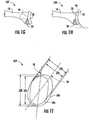
- a pre-operative planning method for designing a glenoid implantis provided. Such a method can be separate from a pre-operative planning method for the humerus, or can in some embodiments be done in conjunction with the planning for the humerus, or humeral side of the joint. Such planning steps particular to the glenoid side of the joint can comprise analysis steps such as those depicted in Figures 1A-11 .
- a pre-operative planning method for the glenoidcan comprise a step 101, as depicted in Figure 1A , where the anterior edge 18 of glenoid implant 20 can be aligned 30 with anterior edge 16 of glenoid 12 of scapula bone 10 of a patient to be treated.
- this stepcan be accomplished virtually based on images, e.g. CT images or X-ray images, taken from a subject or patient prior to surgery.
- anterior edge 18 of glenoid implant 20By aligning anterior edge 18 of glenoid implant 20 with anterior edge 16 of glenoid 12, data and information can be collected that informs the selection of a glenoid implant, and/or supports the creation of a patient-specific augmented glenoid implant, and/or supports the creation of a shoulder surgery guide device specific to the patient or subject to be treated.
- a pre-operative planning method for the glenoidcan comprise a step 102, as depicted in Figure 1B , where the retroversion 32 of glenoid implant 20 is adjusted and/or measured.
- the retroversionis the placement or degree of posterior rotation of glenoid implant 20 when glenoid 12, including posterior wear 14 (see Figure 1A ), is reamed or otherwise resurfaced to accommodate glenoid implant 20.
- adjusting the retroversioncomprises adjusting the retroversion to be about 5 degrees (5°) to about 10 degrees (10°), with a maximum of 10°.
- this analysiscan be accomplished virtually based on images taken from a subject or patient prior to surgery.
- data and informationcan be collected that informs the selection of a glenoid implant, and/or design and production of a patient-specific augmented glenoid implant, and/or supports the creation of a shoulder surgery guide device specific to the patient or subject to be treated.
- a pre-operative planning method for the glenoidcan comprise a step 103, as depicted in Figure 1C , where a determination can be made as to the necessity of augmentation 34 to support glenoid implant 20.
- augmentationcan be necessary and/or desirable to provide adequate support for the placement and/or attachment of implant 20.
- Such a step or analysiscan in some embodiments comprise adjusting, sizing and/or measuring augmentation 34 needed. In some embodiments, this analysis can be accomplished virtually based on images taken from a subject or patient prior to surgery.
- data and informationcan be collected that informs the selection of a glenoid implant, and/or design and production of a patient-specific augmented glenoid implant, and/or supports the creation of a shoulder surgery guide device specific to the patient or subject to be treated.
- a pre-operative planning method for the glenoidcan comprise a step 104, as depicted in Figure 1D , where the inferior tilt 36 of glenoid implant 20 can be measured and/or assessed.
- a measurement of inferior tilt 36 of glenoid implant 20can be in comparison to the tilt of the native glenoid in a subject to be treated. In some embodiments, this analysis can be accomplished virtually based on images taken from a subject or patient prior to surgery.
- data and informationcan be collected that informs the selection of a glenoid implant, and/or supports the design and production of a patient-specific augmented glenoid implant, and/or supports the creation of a shoulder surgery guide device specific to the patient or subject to be treated.
- a pre-operative planning method for the glenoidcan comprise a step 105, as depicted in Figure 1E , where the bone support 38 for glenoid implant 20 can be measured and/or assessed.
- Such an assessmentcan in some embodiments comprise characterizing and/or quantifying the amount or degree of bone support 38 for back side 22 of implant 20, taking into consideration posterior wear 14 (see, e.g., Figures 1A or 1C ; or wear at other locations of glenoid 12 not depicted). In some embodiments, this analysis can be accomplished virtually based on images taken from a subject or patient prior to surgery.
- data and informationcan be collected that informs the selection of a glenoid implant, and/or supports the design and production of a patient-specific augmented glenoid implant, and/or supports the creation of a shoulder surgery guide device specific to the patient or subject to be treated.
- a pre-operative planning method for the glenoidcan comprise a step 106, as depicted in Figure 1F , where medialization 42 of glenoid implant 20 can be adjusted and/or characterized by assessing the volumetric amount 40 of bone needed to be removed by reaming. In some embodiments, this analysis can be accomplished virtually based on images taken from a subject or patient prior to surgery. By assessing the bone support 38, data and information can be collected that informs the selection of a glenoid implant, and/or supports the design and production of a patient-specific augmented glenoid implant, and/or supports the creation of a shoulder surgery guide device specific to the patient or subject to be treated.
- a pre-operative planning method for the glenoidcan comprise a step 107, as depicted in Figure 1G , where fixation support in the absence of a central peg 44 that penetrates a vault medially of scapula 10 can be analyzed.
- fixation support in the absence of a central peg 44 that penetrates a vault medially of scapula 10can be analyzed.
- this analysiscan be accomplished virtually based on images taken from a subject or patient prior to surgery.
- fixation supportBy assessing the fixation support, data and information can be collected that informs the selection of a glenoid implant, and/or supports the design and production of a patient-specific augmented glenoid implant, and/or supports the creation of a shoulder surgery guide device specific to the patient or subject to be treated.
- a pre-operative planning method for the glenoidcan comprise a step 108, as depicted in Figure 1H , where a joint line can be analyzed by comparing an original joint line 46 with a new joint line 48 as created when implant 20 is affixed to the glenoid surface of scapula 10.
- the degree to which the joint line changes or shifts, and/or the change in the angle,can be used in optimizing the implant 20 selection and/or placement.
- analyzing the joint lineincluding comparing the original joint line and the new joint line, can comprise analyzing the humeral head lateralization.
- Humeral head lateralizationcan comprise the distance the humeral shaft is moved laterally relative to the scapula after the implants are placed. In some embodiments, this analysis can be accomplished virtually based on images taken from a subject or patient prior to surgery. By assessing the joint line, data and information can be collected that informs the selection of a glenoid implant, and/or supports the design and production of a patient-specific augmented glenoid implant, and/or supports the creation of a shoulder surgery guide device specific to the patient or subject to be treated.
- a pre-operative planning method for the glenoidcan comprise a step 109, as depicted in Figure 1I , where the widths of the glenoid implant 50a and the glenoid bone 50b can be measured and matched after reaming and aligning inferior 56 and superior 58 axes of the glenoid implant and bone.
- a glenoid implant 50a height 52a and width 54acan be measured and aligned with a glenoid bone 50b height 52b and width 54b along inferior 56 and superior 58 axes.
- this analysiscan be accomplished virtually based on images taken from a subject or patient prior to surgery.
- glenoid implant 50a and the glenoid bone 50bBy measuring the widths of the glenoid implant 50a and the glenoid bone 50b, and aligning inferior 56 and superior 58 axes of the glenoid implant and bone, data and information can be collected that informs the selection of a glenoid implant, and/or supports the design and production of a patient-specific augmented glenoid implant, and/or supports the creation of a shoulder surgery guide device specific to the patient or subject to be treated.
- Such planning steps particular to the glenoid side of the jointcan comprise analysis steps such as those depicted in Figures 1A-1I , and can comprise all or some of the steps depicted in Figures 1A-11 , and in some aspects can be done in any order desired.
- analysis steps particular to fixation elementscan be performed first followed by analysis steps particular to joint articulation.
- a pre-operative planning method for designing and producing a shoulder surgery guidefor designing a guide for the humerus, or humeral bone.
- Such a methodcan be separate from a pre-operative planning method for the glenoid (discussed above and depicted in Figures 1a-1I ), or can in some embodiments be done in conjunction with the planning for the glenoid, or glenoid side of the joint.
- Such planning steps particular to the humerus side of the jointcan comprise analysis steps such as those depicted in Figures 2A-2D .
- a pre-operative planning method for the humeruscan comprise a step 201, as depicted in Figure 2A , where the diameter d of humeral head 60 of humerus 62 can be measured.
- this analysiscan be accomplished virtually based on images taken from a subject or patient prior to surgery.
- data and informationcan be collected that informs the selection of a humeral head implant, and/or supports the design and production of a patient-specific augmented glenoid implant, and/or supports the creation of a shoulder surgery guide device specific to the patient or subject to be treated.
- a pre-operative planning method for the humeruscan comprise a step 202 , as depicted in Figure 2B , where the height h of humeral head 60 of humerus 62 can be measured.
- this analysiscan be accomplished virtually based on images taken from a subject or patient prior to surgery.
- data and informationcan be collected that informs the selection of a humeral head implant, and/or supports the design and production of a patient-specific augmented glenoid implant, and/or supports the creation of a shoulder surgery guide device specific to the patient or subject to be treated.
- a pre-operative planning method for the humeruscan comprise a step 203, as depicted in Figure 2C , where the size of a humeral bone implant stem portion 70 can be determined from Houndsfield units (the Hounsfield scale, named after Sir Godfrey Newbold Hounsfield, is a quantitative scale for describing radiodensity) measured by CT scan. In some embodiments, this analysis can be accomplished virtually based on images taken from a subject or patient prior to surgery.
- Houndsfield unitsthe Hounsfield scale, named after Sir Godfrey Newbold Hounsfield, is a quantitative scale for describing radiodensity
- a humeral bone implantBy measuring the size of a humeral bone implant, data and information can be collected that informs the selection of a humeral head implant, and/or supports the design and production of a patient-specific augmented glenoid implant, and/or supports the creation of a shoulder surgery guide device specific to the patient or subject to be treated.
- a pre-operative planning method for the humeruscan comprise a step 204, as depicted in Figure 2D , where a best fit size of humeral implant 72 (the humeral implant includes the humeral head 72 and the humeral stem 70 ) from a range of sizes can be determined.
- the range of sizescan be selected from the group consisting of length of stem, size of humeral stem, diameter of stem, size diameter of head, height of head, and offset of the center spherical head compared to the center of the face of the humeral stem. In some embodiments, this analysis can be accomplished virtually based on images taken from a subject or patient prior to surgery.
- humeral implant 72By determining the most appropriate size of humeral implant 72, data and information can be collected that informs the selection of a humeral head implant, and/or supports the design and production of a patient-specific augmented glenoid implant, and/or supports the creation of a shoulder surgery guide device specific to the patient or subject to be treated.
- Such planning steps particular to the humeral side of the jointcan comprise analysis steps such as those depicted in Figures 2A-2D , and can comprise all or some of the steps depicted in Figures 2A-2D , and in some aspects can be done in any order desired.
- analysis steps particular to joint articulationcan be performed first followed by analysis steps particular to fixation elements.
- a pre-operative planning method for designing and/or producing an augmented glenoid implant and/or a shoulder surgery guidecan comprise comparing vectors 80 in three dimensions to measure the distance of relocation of humeral tuberosity 72 compared to the scapula 10, as depicted in analysis 205 in Figure 3 .
- These tendonscontrol much of the rotation of the humerus about the scapula as well as having a part in elevating the humerus.
- kinematics and kinetics of the glenohumeral jointchange.
- changing the direction of vector 80can change wear patterns and range of motion (ROM) of the implanted device versus the native joint.
- ROMrange of motion
- changing the magnitude of vector 80 by lengthening or increasing it with a joint prosthesis that is too large for the jointcan result in decreased ROM, pain, and increased wear of the prosthetic components.
- changing the magnitude of vector 80 by decreasing or shortening it with a joint prosthesis that is too small for the jointcan result in an unstable joint that may dislocate and can result in suboptimal mechanics for elevating the humerus.
- this analysiscan be accomplished virtually based on images taken from a subject or patient prior to surgery.
- vector 80in three dimensions to measure the distance of relocation of humeral tuberosity 72 compared to the scapula 10
- data and informationcan be collected that informs the selection of a humeral head implant, glenoid implant, and/or supports the design and production of a patient-specific augmented glenoid implant, and/or supports the creation of a shoulder surgery guide device specific to the patient or subject to be treated.
- a pre-operative planning method for designing and/or producing an augmented glenoid implant and/or a shoulder surgery guidecan comprise a step 206, as depicted in Figure 4 , where range of motion (ROM) analysis 82 can be conducted, including virtually positioning implants 20, 72 through extreme ranges of motion to measure impact locations and compensate for necessary functional ROM. In some embodiments, this analysis can be accomplished virtually based on images taken from a subject or patient prior to surgery.
- ROMrange of motion
- glenoid implants 20 and/or humeral implants 72By measuring the ROM with respect to glenoid implants 20 and/or humeral implants 72, data and information can be collected that informs the selection of glenoid implant, a humeral head implant, and/or supports the design and production of a patient-specific augmented glenoid implant, and/or supports the creation of a shoulder surgery guide device specific to the patient or subject to be treated.
- a pre-operative planning method for designing and/or producing an augmented glenoid implant and/or a shoulder surgery guidecan comprise a step 207, as depicted in Figure 5 , where soft tissue, e.g. muscle, analysis is conducted.
- soft tissue analysiscan comprise determining and/or assessing soft tissue insertion points (e.g., X, Y and Z ) and analyzing impacts on and/or impacts from use of one or more implants (glenoid and/or humeral).
- four rotator cuff muscles and their attachments pointscan be analyzed.
- analysiscan comprise the subscapularis that attaches at an attachment point Y near the lesser tuberosity and at an attachment point X near the anterior glenoid.
- analysiscan comprise the supraspinatus that attaches at an attachment point Z near the anterior greater tuberosity and above the scapular spine (shoulder blade; not shown).
- soft tissue analysiscan comprise the infraspinatus that attaches at the greater tuberosity (posterior to supraspinatus) and below the scapular spine (posterior).
- soft tissue analysiscan comprise the teres minor that attaches posterior on the humerus and on the inferior scapular boder.
- this analysiscan be accomplished virtually based on images taken from a subject or patient prior to surgery.
- data and informationcan be collected that informs the selection of a glenoid implant, a humeral head implant, and/or supports the design and production of a patient-specific augmented glenoid implant, and/or supports the creation of a shoulder surgery guide device specific to the patient or subject to be treated.
- the disclosed pre-operative planning methodscan further comprise designing and/or producing an augmented glenoid implant and/or a shoulder surgery guide device, such as a glenoid placement guide, based upon parameters collected from the planning methods and analyses.
- a designed augmented glenoid implant and/or shoulder surgery guidecan be produced, wherein the produced surgery guide can be configured in accordance with parameters collected from the planning and analysis specific to the patient to be treated.
- a guide, and/or a glenoid prosthetic implantcan be produced or made using a three dimensional (3D) printing device.
- a shoulder surgery guide device and/or glenoid implant produced as disclosed hereincan comprise a polymeric or metallic material.
- the disclosed pre-operative planning methodscan further comprise identifying a prosthetic shoulder implant, and/or designing a patient-specific augmented glenoid implant, and/or identifying a placement position for the prosthetic shoulder implant.
- the design and/or identification of a prosthetic shoulder implant and placement positiontakes into consideration at least one of the factors selected from the group consisting of adjustments in glenoid implant size, augmentation depth, augment position, positioning in six degrees of freedom, fixation type, fixation size, reaming depth, reaming diameter, reaming angle, and/or a combination thereof.
- the above methodcan further comprise a step of recommending implants and placement positions, with recommended adjustments in humerus stem size, length, head diameter, head height, head offset and rotation (axial).
- a prosthetic shoulder implantcan in some embodiments comprise a glenoid implant.
- the above methods of designing and/or creating a glenoid implant, shoulder surgery guide, including a glenoid placement guide, based on pre-operative planningcan further comprise one or more optimization steps.
- optimization stepscan comprise the identification of procedural risks based on measurements of one or more of a plurality of factors.
- factorscan in some embodiments comprise whether the glenoid face coverage is maximized (e.g. about 0 to about 2 mm), the overhang of the glenoid face is minimized (e.g. about 0 to about 3 mm), and/or the bone removal on the glenoid face is minimized, such as for example less than about 2mm of depth.
- such optimization factorscan comprise whether the glenoid retroversion is less than about 5 degrees to about 10 degrees, the seating of the glenoid implant is greater than about 80%, i.e. about 80% of the back side of the glenoid implant is supported by or touching bone, whether there is minimized penetration of the glenoid cortical wall anteriorily (e.g. about 0mm to about 3mm), and/or the depth of any glenoid implant augment feature is as minimal as possible.
- optimization factorscan comprise whether there is less than about 1 mm of difference between the anatomic joint line and the new joint line with implants, there is minimized penetration of the glenoid cortical wall anteriorily, and/or there is maximized bone thickness behind the glenoid, preferably greater than 3mm.
- such optimization factorscan comprise whether the orientation offset between the native glenoid and implant superior/inferior axis is minimized, preferably less than 5 degrees, the superior or inferior tilt versus native glenoid is minimized, preferably less than 5 degrees, there is less than about 5% to about 10% change in soft tissue length at extreme ranges of motion, there is maximized filing of the humeral metaphysis, in some embodiments greater than about 90% of metaphyseal bone filled based on and identification of metaphyseal bone by use of Houndsfield units, there is an absence of a humeral head overhang compared to the cut, or prepared surface of the humeral bone, there is minimal difference in humeral head diameter between anatomic and implant, in some embodiments less than about 3mm, there is minimal difference in humeral head height between anatomic and implant, in some embodiments less than about 1mm, and/or there is greater tuberosity to medial head edge comparison to anatomic, in some embodiments less than about 2mm.
- the penetration of the cortical wall anteriorily of the vaultcan be assessed, as depicted in Figure 6.
- Figure 6depicts step 208 of assessing the penetration of the cortical wall anteriorly of the vault 88 by a support structure 84 of glenoid implant 20.
- an additional or alternate support structure 86can be used to affix implant 20 to glenoid 12.
- the width of the greater tuberosity to medial head edge with an implantcan be compared to the anatomic width.
- the width 90 of the greater tuberosity to medial head edge with an implant 72can be compared to the width of the anatomical humeral head.
- the planning methods and analysis steps disclosed hereincan be done pre-operatively. That is, they can be done prior to surgery in a virtual or software-based environment. Such virtual simulations can in some embodiments be based on images or scans taken from a subject prior to surgery.
- imaging techniquese.g. computed tomography (CT), x-ray imaging, positron emission tomography (PET), ultrasound, etc.
- CTcomputed tomography
- PETpositron emission tomography
- ultrasoundetc.
- DICOMDigital Imaging and Communications in Medicine
- DICOMcan in some embodiments provide for the integration of scanners, servers, workstations, printers, and network hardware from multiple manufacturers into a picture archiving and communication system (PACS).
- PACSpicture archiving and communication system
- Application areas for DICOM Imagesare CT, MRI, PET, and Ultrasound, among others.
- the actual morphologic form of the native glenoid bone of a patient to be treatedis considered and imaged.
- the form of the glenoid as found on a CT scanis used to create a "reverse image” that is incorporated in the implant design.
- the form of the glenoid as found on a CT scanis used to create a "reverse image” that is incorporated in the guide design.
- the subject matter described hereinmay be implemented in software in combination with hardware and/or firmware.
- the subject matter described hereinmay be implemented in software executed by a processor.
- the subject matter described hereinmay be implemented using a computer readable medium having stored thereon computer executable instructions that when executed by the processor of a computer control the computer to perform steps.
- Exemplary computer readable media suitable for implementing the subject matter described hereininclude non-transitory devices, such as disk memory devices, chip memory devices, programmable logic devices, and application specific integrated circuits.
- a computer readable medium that implements the subject matter described hereinmay be located on a single device or computing platform or may be distributed across multiple devices or computing platforms.
- the disclosed pre-operative planning methodscan further comprise providing a computer readable medium having stored thereon executable instructions that when executed by the processor of a computer control the computer to perform one or more of the planning method and/or analysis steps.
- computer readable mediumcan have stored thereon executable instructions that when executed by the processor of a computer can control the computer to generate a virtual 3D model of an augmented or patient-specific glenoid implant and/or a glenoid guide device, e.g. a glenoid placement guide, reflecting one or more optimized parameters determined during pre-operative planning.
- computer readable mediumcan have stored thereon executable instructions that when executed by the processor of a computer control the computer to control a 3D printing device in communication with the computer, whereby the 3D printing device can print a patient-specific, i.e. customized, augmented glenoid implant and/or a glenoid guide device or humeral guide device for use in shoulder replacement surgery in a patient for which pre-operative planning method steps were conducted.
- a computer readable mediumcan be provided having stored thereon executable instructions that when executed by a processor of a computer can control the computer to generate a virtual 3D model of a patient-specific, i.e. customized, augmented glenoid implant and/or a glenoid implant device or placement guide device reflecting one or more optimized parameters determined during pre-operative planning.
- a computer readable mediumis provided, wherein the computer readable medium has stored thereon executable instructions that when executed by the processor of a computer control the computer to perform one or more of the planning method and/or analysis steps as disclosed herein.
- computers, computing devices, hardware and/or functionality described hereinmay constitute a special purpose test device. Further, computers, computing devices, hardware and/or functionality described herein can improve the technological field of pre-operative planning for shoulder surgery and can improve generation of virtual modeling systems.
- a computing platform, computer, computing device, and/or hardware that implements the subject matter described hereinmay comprise a special purpose computing device usable to generate 3D models of glenoid and/or humeral implant devices, and/or for modeling and virtually simulating pre-operative shoulder surgery analysis.
- noderefers to a physical computing platform including one or more processors and memory.
- the terms “function” or “module”refer to hardware, firmware, or software in combination with hardware and/or firmware for implementing features described herein.
- a computer readable mediumhaving stored thereon executable instructions that when executed by the processor of a computer control the computer to perform steps comprising generating a virtual three dimensional model of a glenoid and/or humeral guide reflecting one or more optimized parameters determined during pre-operative planning based on the above method steps.
- a computer readable mediumis provided, having stored thereon executable instructions that when executed by the processor of a computer control a 3D printing device in communication with the computer, whereby the 3D printing device prints a glenoid and/or humeral guide, or placement guide, for use in shoulder replacement surgery in a patient for which the optimization analysis was conducted.
- glenoid implantsand particularly customized or patient-specific glenoid implant, including those with patient-specific augmentation, can be designed, simulated and in some instances produced for use in shoulder surgery.
- Such a surgery guide deviceis depicted in Figures 8A-16B and 12A-12I .
- FIGs 8A and 8Bare perspective and cut-away views, respectively, of a standard glenoid implant 300.
- a glenoid implantcan in some aspects comprise a central body 302, in some embodiments comprising a polyethylene material, wherein central body 302 can comprise a lateral articulating surface 310 on a first side (top side), sidewalls 312, a substantially flat second side (bottom side) 314, and one or more affixation components 320, such as for example a peg or keel (depicted in Figures 8A and 8B ) extending from second or bottom side 314.
- affixation components 320such as for example a peg or keel (depicted in Figures 8A and 8B ) extending from second or bottom side 314.
- a glenoid implant 300 with a substantially flat bottom side 314will not fit well against a glenoid of a patient, particularly where there is substantial wear.
- a glenoid implant with an augmented back or bottom sidecan provide a better fit or seat on the native glenoid surface of a patient.
- FIGS 9A and 9Bare perspective and cut-away views, respectively, of a glenoid implant 400 with an augmentation 416.
- a glenoid implantcan in some aspects comprise a central body 402, in some embodiments comprising a polyethylene material, wherein central body 402 can comprise a lateral articulating surface 410 on a first side (top side), sidewalls 412, a substantially flat second side (bottom side) 414 (except where augmentation 416 exists), and one or more affixation components 320, such as for example a peg or keel (depicted in Figures 8A and 8B ) extending from second or bottom side 314. Dashed line 418 depicts the location of bottom side) 414 in the absence of augmentation 416.
- Figures 10A and 10Bare perspective and cut-away views, respectively, of a glenoid implant 500 with patient-specific back-side augmentation 516.
- the patient-specific back-side augmentation 516can be designed based on pre-operative planning and analysis as disclosed herein.
- Such a glenoidcan be considered or referred to in some embodiments as a custom or adaptive glenoid implant that is tailored and/or designed specifically for a patient given the structure, shape and/or condition of the native glenoid surface of the patient.
- Such a glenoid implantcan in some aspects comprise a central body 402, in some embodiments comprising a polyethylene material, wherein central body 402 can comprise a lateral articulating surface 410 on a first side (top side), sidewalls 412, a substantially flat second side (bottom side) 414 (except where augmentation 416 exists), and one or more affixation components 320, such as for example a peg or keel (depicted in Figures 8A and 8B ) extending from second or bottom side 314.
- the central bodyincluding the lateral articulating surface, can be substantially circular, oval or pear-shaped.
- the shape of the glenoid implantapproximates the shape of the natural glenoid cavity.
- the lateral articulating surfaceprovides a surface upon which the humeral head can articulate.
- the augmentation of a glenoid disclosed hereincan comprise an augmented feature or features extending from the second, or back side, of the glenoid implant.
- the second side of the glenoid implantis that which comes into contact with the bone of the scapula where the glenoid implant is seated, i.e. where the natural glenoid cavity was prior to insertion of the implant.
- the augmentationcan in some embodiments enhance or improve the stability and contact between the glenoid implant and existing bone.
- an augmentation on the back side of a glenoid implantcan be designed to align or match the shape and dimension of the cavity in the scapula where the glenoid is to be seated.
- the depth of the augmentation, size of the augmentation, and/or radial position of the augmentation on the second surface of the glenoid implantcan be varied as desired given a particular situation, i.e. customized to fit the reamed glenoid cavity of the patient.
- variable augmented glenoid implant or prosthesiswherein the variable augmentation is defined by one or more of the following: the depth of augmentation, the size of augmentation, the shape of the augmentation and/or the radial position of augmentation.
- the depth of the augmentationcan range from about 2 mm to about 4 mm.
- the augmentationcan be small in size with respect to the size of the glenoid implant, e.g., can cover about 5%, 10%, 15%, 20%, 30%, 40%, 50%, or more of the back side of the glenoid implant, or can be large in size with respect to the size of the glenoid implant, e.g., can cover about 50%, 60%, 70%, 80%, 90%, 95% or greater of the back side of the glenoid implant.
- the shape of the augmentationcan for example comprise a plate-like shape, sphere-like shape (fixed curvature, ellipsoid-like structure), cone like shape, a pyramid like shape or the like.
- the positioning of the augmentation on the second surface or back side of the glenoidcan also vary, and can be located on the posterior and/or anterior side of the second surface, and/or at a superior and/or inferior location of the second surface of the glenoid implant.
- the augmentationcan be patient specific and/or patient tailored.
- the patient "specific" augmentationis generated by a geometric representation that best fits the joint surface, and does not consider that the joint surface necessarily needs to be altered in any way prior to implantation of the implant. In the case of a patient "tailored", the best fit implant is chosen, with a consideration for minimization of bone surface alteration to achieve minimally acceptable or optimal interface characteristics between the surface of the scapula bone and the implant.
- the geometric representationcan be plate (best fit plane), and/or spherical (best-fit-sphere), and/or ellipsoid (best-fit-ellipsoid).
- the radius of curvaturecould vary from ⁇ to 10.
- the geometric representationcan depend on the wear surface and orientation.
- a joint surfacecan be represented by 4 spheres with 4 different radi of curvature and 4 different sphere centers.
- the augmentationcan co-exist on the second surface of the glenoid implant along with a fixation component, e.g. a keel or peg.
- the fixation componentcan be located at any desirable position on the second surface of the glenoid implant, including for example in the center or medial position, at an inferior position, at a superior position, and/or in multiple locations, e.g. double fixation components.
- the fixation componentcan have a free position on the backside surface and can be located according to the bony stock orientation of the patient in order to provide stable fixation and steady stress and strain distribution.
- the dimensions of the fixation elementscan in some embodiments be patient tailored and their dimensions can be defined using correspondence matrix between a three dimensional (3D) bony structure of the patient and a statistical shape based atlas according to the following steps:
- a statistical mean shape modelcan be matched to the patient bone using rigid and/or non-rigid registration process in order to find the best fit between both shapes.
- the statistical mean shapecan be deformed to fit well the size and the shape of the patient bone.
- Correspondence landmarks and/or regions, pathologic or not pathologiccan be used to guide the registration process.
- the shape parameters(Eigen values and eigen vectors) can be defined according to the deformation of the statistical mean shape. These shape parameters can be based on the principle variation modes of the model.
- the extracted shape parameterscan define the best fixation configuration based on the correspondence transformation between the mean SSM and the patient bone.
- verifying the surrounding bone densitycan be done to evaluate the stability of the bone fixation.
- a statistical shape modelcan be used as a component of any of the pre-operative analysis and modeling methods and techniques, including the use of a statistical appearance shape model, and/or parametric or non-parametric modeling.
- a glenoid implantcan be configured as described in Table 1, and as depicted in Figures 11A-16B . As would be appreciated by one of ordinary skill in the art, other configurations are possible without departing from the scope of the instant disclosure. Table 1.
- Example 1( Figure 11 )
- Example 2( Figure 12 )
- Example 3( Figure 13 )
- Example 4( Figure 14 )
- Example 5( Figure 15 )
- Example 6( Figure 16 ) Augmentation Depth 2mm 2mm 4mm 4mm 2mm 2mm Augmentation Size Small Large Large Large Large Small Small Augmentation Position Posterior/Superior Posterior/Superior Posterior/Inferior Posterior Posterior/Inferior Augmentation shape 2 Best-fit spheres 2 Best fit spheres 4 best-fit-spheres 3 best fit spheres 2 best-fit-sphere 1 best-fit-sphere Fixation Component Type/position Centered Inferior Double Superior Double Central Fixation Component diameter/depth 4mm/8mm 5mm/12mm 6mm/9mm 6.5mm/9.5mm 4mm/8mm 4.5mm/8.5mm
- FIGS 11A and 11Bare rear and rear-perspective views, respectively, of an exemplary glenoid implant 600 with patient-specific augmentation 605.
- a glenoid implantcan in some aspects comprise a central body 604, in some embodiments comprising a polyethylene material, wherein central body 604 can comprise a lateral articulating surface on a first side (front/top side), sidewalls 602, a substantially flat second side (bottom side) 601 (except where augmentation 605 exists), and an affixation component 603, such as for example a peg as depicted in in Figures 11A and 11B ) extending from second or bottom side 601.
- the exemplary patient-specific augmentation 605 depicted in Figures 11A and 11Bcan comprise an about 2 mm deep, relatively small augmentation, located at a posterior/superior position with respect to the native glenoid surface to which it will be seated.
- the augmentation shapecan comprise two best-fit spheres, and the affixation component can comprise a substantially centered single peg having a diameter of about 4 mm and a depth of about 8 mm.
- FIGS 12A and 12Bare rear and rear-perspective views, respectively, of an exemplary glenoid implant 610 with patient-specific augmentation 615.
- a glenoid implantcan in some aspects comprise a central body 614, in some embodiments comprising a polyethylene material, wherein central body 614 can comprise a lateral articulating surface on a first side (front/top side), sidewalls 612, a substantially flat second side (bottom side) 611 (except where augmentation 615 exists), and an affixation component 613, such as for example a peg as depicted in in Figures 12A and 12B , extending from second or bottom side 611.
- the exemplary patient-specific augmentation 615 depicted in Figures 12A and 12Bcan comprise an about 2 mm deep, relatively large augmentation, located at a posterior/superior position with respect to the native glenoid surface to which it will be seated.
- the augmentation shapecan comprise two best-fit spheres, and the affixation component can comprise a single peg located at an inferior position and having a diameter of about 5 mm and a depth of about 12 mm.
- FIGS 13A and 13Bare rear and rear-perspective views, respectively, of an exemplary glenoid implant 620 with patient-specific augmentation 625.
- a glenoid implantcan in some aspects comprise a central body 624, in some embodiments comprising a polyethylene material, wherein central body 624 can comprise a lateral articulating surface on a first side (front/top side), sidewalls 622, a substantially flat second side (bottom side) 621 (except where augmentation 625 exists), and an affixation component or components 623a/623b , such as for example pegs as depicted in in Figures 13A and 13B , extending from second or bottom side 621.
- the exemplary patient-specific augmentation 625 depicted in Figures 13A and 13Bcan comprise an about 4 mm deep, relatively large augmentation, located at a posterior position with respect to the native glenoid surface to which it will be seated.
- the augmentation shapecan comprise four best-fit spheres, and the affixation components can comprise a pair of pegs having a diameter of about 6 mm and a depth of about 9 mm.
- FIGS 14A and 14Bare rear and rear-perspective views, respectively, of an exemplary glenoid implant 630 with patient-specific augmentation 635.
- a glenoid implantcan in some aspects comprise a central body 634, in some embodiments comprising a polyethylene material, wherein central body 634 can comprise a lateral articulating surface on a first side (front/top side), sidewalls 632, a substantially flat second side (bottom side) 631 (except where augmentation 635 exists), and an affixation component 633, such as for example a peg as depicted in in Figures 14A and 14B , extending from second or bottom side 631.
- the exemplary patient-specific augmentation 635 depicted in Figures 14A and 14Bcan comprise an about 4 mm deep, relatively large augmentation, located at a posterior/inferior position with respect to the native glenoid surface to which it will be seated.
- the augmentation shapecan comprise three best-fit spheres, and the affixation component can comprise a single peg located at an superior position and having a diameter of about 6.5 mm and a depth of about 9.5 mm.
- FIGS 15A and 15Bare rear and rear-perspective views, respectively, of an exemplary glenoid implant 640 with patient-specific augmentation 645.
- a glenoid implantcan in some aspects comprise a central body 644, in some embodiments comprising a polyethylene material, wherein central body 644 can comprise a lateral articulating surface on a first side (front/top side), sidewalls 642, a substantially flat second side (bottom side) 641 (except where augmentation 645 exists), and an affixation component or components 643a/643b , such as for example pegs as depicted in in Figures 15A and 15B , extending from second or bottom side 641.
- the exemplary patient-specific augmentation 645 depicted in Figures 15A and 15Bcan comprise an about 2 mm deep, relatively small augmentation, located at a posterior position with respect to the native glenoid surface to which it will be seated.
- the augmentation shapecan comprise two best-fit spheres, and the affixation components can comprise a pair of pegs having a diameter of about 4 mm and a depth of about 8 mm.
- FIGS 16A and 16Bare rear and rear-perspective views, respectively, of an exemplary glenoid implant 650 with patient-specific augmentation 655.
- a glenoid implantcan in some aspects comprise a central body 654, in some embodiments comprising a polyethylene material, wherein central body 654 can comprise a lateral articulating surface on a first side (front/top side), sidewalls 652, a substantially flat second side (bottom side) 651 (except where augmentation 655 exists), and an affixation component 653, such as for example a peg as depicted in in Figures 16A and 16B , extending from second or bottom side 651.
- the exemplary patient-specific augmentation 655 depicted in Figures 16A and 16Bcan comprise an about 2 mm deep, relatively small augmentation, located at a posterior/inferior position with respect to the native glenoid surface to which it will be seated.
- the augmentation shapecan comprise one best-fit sphere, and the affixation component can comprise a single peg located at central position and having a diameter of about 4.5 mm and a depth of about 8.5 mm.
- a statistical shape modelcan be used, including the use of a statistical appearance shape model, and/or parametric or non-parametric modeling.
- Figure 17is a schematic illustration of a scapula bone and glenoid surface depicted with defined zones based on statistical shape analysis.
- the multi-curvature glenoid backsidecan be analyzed according to statistical shape analysis.
- principal statistical modes of the glenoid shapehave been defined as depicted in Figure 17 . Based on these modes multiple backside zones with multiple curvatures can be defined.
- a glenoid 710 on a scapula 700 as depicted in Figure 17can comprise a superior/posterior zone 722 that comprises about 13% of the glenoid surface, and having a radius of curvature (RoC) of about 22 mm.
- a superior/anterior zone 724can comprise about 17% of the glenoid surface, and comprise a RoC of about 39 mm.
- An inferior/posterior zone 726can comprise about 43% of the glenoid surface, and comprise a RoC of about 21 mm.
- An inferior/anterior zone 728can comprise about 27% of the glenoid surface, and comprise a RoC of about 21 mm.
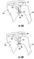
- Figures 18A and 18Bare anterior views of a scapula 700 with a humerus bone 702 , with scapula 700 having a glenoid implant 750 secured thereto and the humerus head articulating thereon, where Figure 18A depicts a glenoid implant 750 with no back-side augmentation and Figure 18B depicting a glenoid implant 750 with back-side augmentation 756.
- glenoid implant 750 with no back-side augmentationis secured to glenoid 704 by, at least in part, augmentation 752, wherein a gap 754 exists between the back side of glenoid implant 750 and face 706 of glenoid bone 704.
- a glenoid implant 750 with back-side augmentation 756is seated or affixed to glenoid 704 , wherein augmentation 756 fills, or at least substantially fills, the gap such that the back-side of glenoid implant 750 more closely matches, and/or securely fits against, the face 706 of the native glenoid 704.
- Such augmentationcan be configured to be patient-specific such that it matches the unique structure and/or surface character of a native glenoid of a patient to be treated.
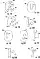
- Figures 19A-19Iare schematic illustrations of patient-specific glenoid implants with customized affixation components.
- affixation componentscan be customized to be patient-specific taking into consideration the native glenoid surface of the patient to be treated and based on pre-operative planning.
- Figure 19Ais a back-side view of a glenoid implant 800 with multiple pegs 901, 902, 903, 904 generally evenly distributed such that glenoid implant 800 is generally universally applicable to some patients.
- glenoid implant 801comprises a keel 910 centrally located and generally vertically oriented such that it is generally universally applicable to some patients.
- Figure 19Cdepicts pegs 901, 902, 903, 904 spatially oriented in a manner that optimizes the securement of glenoid implant 802 to a given native glenoid bone.
- the diameter of the pegscan be varied (see e.g. peg 901 versus peg 902 ) as needed to optimize securement of the implant.
- the depth or length of pegs 901, 902, 903can be varied as depicted in implant 803 in Figure 19D .
- the orientation and/or positioningcan be varied or adjusted as needed to optimize affixation to a native glenoid surface.
- keel 910can be off-set from center.
- keel 910can be angled, or tilted off vertical, in glenoid 805.
- keel 910can be located in a substantially inferior, as depicted in Figure 19G , or superior position.
- keel 911( Figure 19H ) or peg 905 ( Figure 19I ) can be arranged such that they extend from the back-side of glenoid 807 and/or 808 in a substantially perpendicular position but angled at a desired degree to optimize the securement of the glenoid to a native glenoid surface.
- Combinations and/or variations of the exemplary embodiments depicted in Figures 19A-19Iare within the scope of the instant disclosure.
- kitscan in some aspects comprise a set of instructions for performing pre-operative analysis steps as disclosed herein, and one or more guides, glenoid prosthetic devices and/or humeral prosthetic devices.
- a kitcan comprise a 3-D printing device for producing a guide and/or one or more glenoid and/or humeral prosthetic devices.
- a kitcan comprise a computer-readable medium for use in conducting the pre-operative planning, and designing a guide, glenoid implant and/or humeral implant based on input parameters gathered during the pre-operative planning.
- kitscan comprise a range of glenoid implants having augmented back sides where the augmentation is selectable in terms of the augmentation size, shape, and position, both in the superior/inferior and posterior/anterior position.
- a kit comprising a range of glenoid implants having augmented backis provided sides where the augmentation is selectable in terms of its size, shape, and position, where the position is defined by an angular and a radial position.
- methods of treating a patient, and/or surgical methodsare provided wherein one or more of the disclosed methods of analysis and optimization are performed on a patient in need of shoulder or other joint surgery.
- methods of treating a patientare provided wherein a disclosed method of analysis and optimization is performed, an optimized guide is designed and created, and one or more glenoid and/or humeral implants are designed, created, and/or selected.
- a method of treating a patientcan comprise utilizing the pre-operative planning to design and optimize a guide and one or more glenoid and/or humeral implants, and the use of the guide to surgically implant the one or more glenoid and/or humeral prosthetic devices.
- a patientcan comprise a mammalian subject.
- the patientcan be a human subject, including an adult, adolescent or child.
- the term "about,” when referring to a value or to an amount of mass, weight, time, volume, concentration or percentageis meant to encompass variations of in some embodiments ⁇ 20%, in some embodiments ⁇ 10%, in some embodiments ⁇ 5%, in some embodiments ⁇ 1%, in some embodiments ⁇ 0.5%, and in some embodiments ⁇ 0.1% from the specified amount, as such variations are appropriate to perform the disclosed method.
- the phrase “A, B, C, and/or D”includes A, B, C, and D individually, but also includes any and all combinations and subcombinations of A, B, C, and D.
- the phrase “consisting of”excludes any element, step, or ingredient not specified in the claim.
- signalingor “significant” relates to a statistical analysis of the probability that there is a non-random association between two or more entities. To determine whether or not a relationship is “significant” or has “significance”, statistical manipulations of the data can be performed to calculate a probability, expressed as a "p value”. Those p values that fall below a user-defined cutoff point are regarded as significant. In some embodiments, a p value less than or equal to 0.05, in some embodiments less than 0.01, in some embodiments less than 0.005, and in some embodiments less than 0.001, are regarded as significant. Accordingly, a p value greater than or equal to 0.05 is considered not significant.
- patient-specificcan be used interchangeably and can in some embodiments refer to the specialization of such features taking into consideration factors specific to a patient to be treated, including for example characteristics acquired from pre-operative analysis and planning.
Landscapes
- Health & Medical Sciences (AREA)
- Engineering & Computer Science (AREA)
- Life Sciences & Earth Sciences (AREA)
- General Health & Medical Sciences (AREA)
- Biomedical Technology (AREA)
- Heart & Thoracic Surgery (AREA)
- Animal Behavior & Ethology (AREA)
- Public Health (AREA)
- Veterinary Medicine (AREA)
- Oral & Maxillofacial Surgery (AREA)
- Surgery (AREA)
- Orthopedic Medicine & Surgery (AREA)
- Vascular Medicine (AREA)
- Transplantation (AREA)
- Cardiology (AREA)
- Medical Informatics (AREA)
- Nuclear Medicine, Radiotherapy & Molecular Imaging (AREA)
- Molecular Biology (AREA)
- Physics & Mathematics (AREA)
- Geometry (AREA)
- Manufacturing & Machinery (AREA)
- Pathology (AREA)
- Robotics (AREA)
- Prostheses (AREA)
Description
- The presently disclosed subject matter relates to methods, systems and devices for pre-operatively planned adaptive glenoid implants and prostheses. The presently disclosed subject matter also relates to the use of such implants and prostheses in patients undergoing shoulder surgery.
- Shoulder replacement is a common surgical operation that has achieved positive results for many patients. Indeed, approximately 10% of joint replacement procedures globally are related to the shoulder. Many shoulder procedures are performed in a patient where substantially normally bone exists for orientation and fixation of a prosthetic replacement, or resurfacing. In these cases, the need for the shoulder replacement can often times be related mostly to the arthritic condition of the joint, and relative absence of healthy cartilage.
- In some patients, however, one or more of the bones of the shoulder are not only arthritic, but have also had previous conditions that have caused bone to wear away. In such cases, there may not be sufficient bone to adequately affix a prosthetic implant to the bone, or the bones may have been worn such that the orientation of a joint replacement cannot be satisfactorily determined to ensure a positive patient outcome.
- There are a number of factors that complicate the selection, orientation and affixation of prosthetic implant devices, such as glenoid implants and/or humeral implants. Failure to properly account for each factor can lead to improperly sized, misaligned and/or poorly affixed implants that result in a poor surgical outcome for the patient.
- In order to increase the likelihood of successful patient outcomes in patients undergoing shoulder surgery, methods, systems and devices are needed that allow for the full understanding and incorporation of all necessary factors for optimization of shoulder implant selection and placement. In that regard, US Patent Application
US 2009/318929 A1 describes a preoperative planning method for designing a glenoid implant. Thus, a need remains for methods, systems and devices for pre-operatively planned shoulder surgery guides and implants, such as glenoid implants and prostheses, that achieve desired outcomes. - The present invention is a method of pre-operative planning for designing a glenoid implant, according to claim 1. A glenoid implant designed according to the method for a specific patient is also claimed.
- An object of the presently disclosed subject matter having been stated hereinabove, and which is achieved in whole or in part by the presently disclosed subject matter, other objects will become evident as the description proceeds when taken in connection with the accompanying Examples as best described hereinbelow.
- The presently disclosed subject matter can be better understood by referring to the following figures. The components in the figures are not necessarily to scale, emphasis instead being placed upon illustrating the principles of the presently disclosed subject matter (often schematically). In the figures, like reference numerals designate corresponding parts throughout the different views. A further understanding of the presently disclosed subject matter can be obtained by reference to an embodiment set forth in the illustrations of the accompanying drawings. Although the illustrated embodiment is merely exemplary of systems for carrying out the presently disclosed subject matter, both the organization and method of operation of the presently disclosed subject matter, in general, together with further objectives and advantages thereof, may be more easily understood by reference to the drawings and the following description. The drawings are not intended to limit the scope of this presently disclosed subject matter, which is set forth with particularity in the claims as appended or as subsequently amended, but merely to clarify and exemplify the presently disclosed subject matter.
- For a more complete understanding of the presently disclosed subject matter, reference is now made to the following drawings in which:
Figure 1A is a schematic illustration of a step in a pre-operative planning method for designing a shoulder surgery guide where the anterior edge of a glenoid implant is aligned with an anterior edge of a glenoid bone, according to an embodiment of the disclosed subject matter;Figure 1B is a schematic illustration of a step in a pre-operative planning method for designing a shoulder surgery guide where the retroversion of a glenoid implant is adjusted, according to an embodiment of the disclosed subject matter;Figure 1C is a schematic illustration of a step in a pre-operative planning method for designing a shoulder surgery guide where the augmentation of a glenoid implant is adjusted, according to an embodiment of the disclosed subject matter;Figure 1D is a schematic illustration of a step in a pre-operative planning method for designing a shoulder surgery guide where the inferior tilt of a glenoid implant is adjusted, according to an embodiment of the disclosed subject matter;Figure 1E is a schematic illustration of a step in a pre-operative planning method for designing a shoulder surgery guide where bone support for a glenoid implant is evaluated, according to an embodiment of the disclosed subject matter;Figure 1F is a schematic illustration of a step in a pre-operative planning method for designing a shoulder surgery guide where the medialization of a glenoid implant is adjusted by assessing the volumetric amount of bone needed to be removed by reaming, according to an embodiment of the disclosed subject matter;Figure 1G is a schematic illustration of a step in a pre-operative planning method for designing a shoulder surgery guide where fixation support in the absence of central pegs that penetrate a vault medially is analyzed, according to an embodiment of the disclosed subject matter;Figure 1H is a schematic illustration of a step in a pre-operative planning method for designing a shoulder surgery guide where a joint line is analyzed by comparing an original joint line and a new joint line, according to an embodiment of the disclosed subject matter;Figure 1I is a schematic illustration of a step in a pre-operative planning method for designing a shoulder surgery guide where widths of the glenoid implant and the glenoid bone are measured and matched after reaming and aligning inferior and superior axes of the glenoid implant and bone, according to an embodiment of the disclosed subject matter;Figure 2A is a schematic illustration of a step in a pre-operative planning method for designing a shoulder surgery guide where the diameter of a humeral head is determined, according to an embodiment of the disclosed subject matter;Figure 2B is a schematic illustration of a step in a pre-operative planning method for designing a shoulder surgery guide where the height of a humeral head is determined, according to an embodiment of the disclosed subject matter;Figure 2C is a schematic illustration of a step in a pre-operative planning method for designing a shoulder surgery guide where the size of a humeral bone implant from Houndsfield units measured by computed tomography scan is determined, according to an embodiment of the disclosed subject matter;Figure 2D is a schematic illustration of a step in a pre-operative planning method for designing a shoulder surgery guide where a best fit size of implant from a range of sizes is determined, according to an embodiment of the disclosed subject matter;Figure 3 is a schematic illustration of a step in a pre-operative planning method for designing a shoulder surgery guide where vectors are compared in three dimensions to measure the distance of relocation of humeral tuberosity compared to the scapula, according to an embodiment of the disclosed subject matter;Figure 4 is a schematic illustration of a step in a pre-operative planning method for designing a shoulder surgery guide where range of motion analysis is conducted, including virtually positioning implants through extreme ranges of motion to measure impact locations and compensate for necessary functional range of motion, according to an embodiment of the disclosed subject matter;Figure 5 is a schematic illustration of a step in a pre-operative planning method for designing a shoulder surgery guide where soft tissue analysis comprising determining key soft tissue insertion points is conducted, according to an embodiment of the disclosed subject matter;Figure 6 is a schematic illustration of a step in a pre-operative planning method for designing a shoulder surgery guide where penetration of the cortical wall anteriorily of the vault is assessed, according to an embodiment of the disclosed subject matter;Figure 7 is a schematic illustration of a step in a pre-operative planning method for designing a shoulder surgery guide where the width of the greater tuberosity to medial head edge with an implant is compared to the anatomic width, according to an embodiment of the disclosed subject matter;Figures 8A and 8B are perspective and cut-away views, respectively, of a glenoid implant;Figures 9A and 9B are perspective and cut-away views, respectively, of a glenoid implant;Figures 10A and 10B are perspective and cut-away views, respectively, of a glenoid implant with patient-specific back-side augmentation;Figures 11A and 11B are rear and rear-perspective views, respectively, of an exemplary glenoid implant with patient-specific augmentation;Figures 12A and 12B are rear and rear-perspective views, respectively, of an exemplary glenoid implant with patient-specific augmentation;Figures 13A and 13B are rear and rear-perspective views, respectively, of an exemplary glenoid implant with patient-specific augmentation;Figures 14A and 14B are rear and rear-perspective views, respectively, of an exemplary glenoid implant with patient-specific augmentation;Figures 15A and 15B are rear and rear-perspective views, respectively, of an exemplary glenoid implant with patient-specific augmentation;Figures 16A and 16B are rear and rear-perspective views, respectively, of an exemplary glenoid implant with patient-specific augmentation;Figure 17 is a schematic illustration of a scapula bone and glenoid surface depicted with defined zones based on statistical shape analysis;Figures 18A and 18B are anterior views of a scapula with a humerus bone, with the scapula having a glenoid implant secured thereto and the humerus head articulating thereon, whereFigure 18A depicts a glenoid implant with no back-side augmentation andFigure 18B depicting a glenoid implant with back-side augmentation; andFigures 19A-19I are schematic illustrations of patient-specific glenoid implants with customized affixation components.- Patients requiring shoulder surgery may have one or more of the bones of the shoulder that are not only arthritic, but may also have had previous conditions that have caused bone to wear away. In such cases, there may not be sufficient bone to adequately affix a prosthetic implant to the bone during a routine shoulder surgery. Indeed, the bones may have been worn such that the orientation of a joint replacement cannot be satisfactorily determined to ensure a positive patient outcome.
- The glenoid bone can be subject to increased wear due to bone arthritic conditions of the joint, and due to alterations of a normal soft tissue envelope surrounding the joint. In such cases, the orientation of the face of the glenoid portion of the scapula bone may be altered so that the humeral bone is no longer appropriately apposed to the glenoid surface. In the case where the glenoid is severely worn, there can be two or more risks a surgeon must balance in an attempt to improve shoulder function and pain relief.
- First, if the optimal orientation of the diseased but treated shoulder is not found and replicated with the prosthesis the patient may experience most operative complications related to subluxation or dislocation of the replaced shoulder joint. This can occur either due to passive inputs to the shoulder (e.g., leaning against it, or lying in bed), or due to active firing of surrounding soft tissue which is not able to be constrained by the replaced joint surfaces.
- Additionally, the fixation of a replacement prosthesis, or implant, to the native patient bone can be problematic. Frequently, in order to counteract the risks associated with joint subluxation and dislocation described above, it can be necessary for a surgeon to orient or position the replacement prosthesis or implant in a position better suited to resist imbalanced muscle forces. In such cases, separation forces between the implant and the bone can increase, which in turn can increase the potential for loosening of the joint prosthesis in the bone. Implant loosening can be related to accelerated implant wear, bone erosion, increased tissue inflammation, joint synovitis, and pain.
- In patients that have undergone shoulder replacement surgery, range of motion and strength are dependent on shoulder kinematics, which are in turn dependent on a host of factors. Such factor can, for example, include for example implant size, implant position, the design of implant shape, the joint line and soft tissue tension. In some cases it can be difficult to predict optimal implant size and position/orientation using currently available guides and implants. Often times a surgeon finds that there are too many variables to manage at one time. Moreover, the size choices of implants can be limited to the lowest practically functional groups to reduce economic burden to the health care system. Current implant designs and methodologies are inadequate to address these challenges because they are of significant cost, require time to develop, include increased risk of implant failure, and rely on human judgment of potential outcomes post-operatively.
- There are many factors that can affect the optimal positioning of shoulder implants during replacement surgery. For example, such factors can include the patient size, relative bone wear, soft tissue strength and condition, six degrees-of-freedom positioning of the glenoid and/or the humeral prosthesis, selected implant size, preoperative patient activity and strength levels, post operative treatment protocols, size and density of patient bone. Additional factors can include patient smoking status, concomitant handicaps and/or patient problems. It can be quite difficult for a surgeon to understand and balance these factors simultaneously. In addition, only a few of these factors are able to be controlled by the surgeon. Finally, each factor does not necessarily have an equally weighted impact on patient outcome. Nevertheless, it is considered that the implant size, position, orientation and bone preparation of the glenoid and the humerus can have a significant impact on the surgical outcomes.
- A factor that further complicates, or makes more difficult, a surgeons task of optimally placing a replacement component or implant to counteract these risk is the fact that the condition of the scapula is such that few landmarks exists for the surgeon the comprehend the implant position within the bone. Thus, frequently a surgeon might find that the implant position is not replicating as was envisioned during the surgical intervention.
- Others have attempted to improve a surgeon's chance of providing successful patient outcomes by providing operative techniques and tools. What is missing, however, is the ability to fully understand and incorporate multiple factors to optimize the implant selection and placement. Specifically, in some embodiments, the success of the surgery can be highly dependent on both the selection of the matching prosthesis or prostheses (humeral and/or glenoid), as well as positioning of this prosthesis, as well as the soft tissue status before the surgery. There have been no previous attempts at including these factors in surgical planning and implant design.
- Disclosed herein are methods, systems and devices for pre-operatively planned shoulder surgery guides, including glenoid placement guides, and implants. Methods, systems and devices are provided for the replacement of the shoulder joint, such as the glenohumeral joint, wherein the conditions of the humeral and soft tissue envelop is taken into consideration. More specifically, what is considered is that the shape and position of the glenoid implant is not based solely on what can be seen and measured on the scapula, but can be chosen, designed, planned and placed with incorporation of the same information related to the humerus. After all, the shoulder is a two part joint, i.e. glenoid and humeral head, wherein both parts work in conjunction with one another, and the factors that affect performance of the device can in some embodiments include factors from both sides of the joint.
- Appropriate sizing of the prosthesis can be important to successful outcomes, knowing that oversized or "overstuffed" replacement shoulders are more likely to dislocate, loosen, be painful, and/or have decreased range of motion. Replaced joints where the orientation of the prostheses is improper increases the likelihood of implant dislocation and loosening. Additionally, over-reaming, or too much bone removal, either on the glenoid, or the humerus, can be the cause of implant loosening, "under-stuffing" or inappropriate articular surface placement which can increase pain and decrease range of motion.
- Provided herein in some embodiments is a glenoid implant designed and manufactured to specifically match the patient anatomy, including optimal humeral and/or glenoid implant size and shape, and taking into account one or more of the following factors: assessment of the humeral implant fit to the humeral bone; relative hardness of the patient bone preoperatively; height and diameter of the humeral head placed on the humeral stem; orientation, or "offset" of the humeral head; and optimal bone removal for preservation of soft tissue insertion and attachment.
- In some embodiments, an adaptive glenoid implant as disclosed herein can comprise an augmented glenoid implant wherein the augmentation is included on the back side of the glenoid implant. A glenoid implant can comprise a central body, in some embodiments comprising a polyethylene material, wherein the central body comprises a lateral articulating surface on a first side (top side), sidewalls, a substantially flat second side (bottom side), and one or more pegs or keels extending from the second side. In some embodiments the central body, including the lateral articulating surface, can be substantially circular, oval or pear-shaped. In some embodiments, the shape of the glenoid implant approximates the shape of the natural glenoid cavity. In some aspects, the lateral articulating surface provides a surface upon which the humeral head can articulate.
- In some embodiments, the augmentation of a glenoid disclosed herein can comprise an augmented feature or features extending from the second, or back side, of the glenoid implant. The second side of the glenoid implant is that which comes into contact with the bone of the scapula where the glenoid implant is seated, i.e. where the natural glenoid cavity was prior to insertion of the implant. Thus, the augmentation can in some embodiments enhance or improve the stability and contact between the glenoid implant and existing bone. In some aspects, an augmentation on the back side of a glenoid implant can be designed to align or match the shape and dimension of the cavity in the scapula where the glenoid is to be seated. By way of example and not limitation, in some aspects, the depth of the augmentation, size of the augmentation, and/or radial position of the augmentation on the second surface of the glenoid implant can be varied as desired given a particular situation, i.e. customized to fit the reamed glenoid cavity of the patient.
- In some embodiments, a variable augmented glenoid implant or prosthesis is provided, wherein the variable augmentation is defined by one or more of the following: the depth of augmentation, the size of augmentation, the shape of the augmentation and/or the radial position of augmentation. By way of example and not limitation, the depth of the augmentation can range from about 2 mm to about 4 mm. Further, the augmentation can be small in size with respect to the size of the glenoid implant, e.g., can cover about 5%, 10%, 15%, 20%, 30%, 40%, 50%, or more of the back side of the glenoid implant, or can be large in size with respect to the size of the glenoid implant, e.g., can cover about 50%, 60%, 70%, 80%, 90%, 95% or greater of the back side of the glenoid implant. The shape of the augmentation can for example comprise a plate-like shape, sphere-like shape (fixed curvature, ellipsoid-like structure), cone like shape, a pyramid like shape or the like. The positioning of the augmentation on the second surface or back side of the glenoid can also vary, and can be located on the posterior and/or anterior side of the second surface, and/or at a superior and/or inferior location of the second surface of the glenoid implant. In some embodiments, the augmentation can be patient specific and/or patient tailored. In some aspects, the patient "specific" augmentation is generated by a geometric representation that best fits the joint surface, and does not consider that the joint surface necessarily needs to be altered in any way prior to implantation of the implant. In the case of a patient "tailored", the best fit implant is chosen, with a consideration for minimization of bone surface alteration to achieve minimally acceptable or optimal interface characteristics between the surface of the scapula bone and the implant. In some embodiments, the geometric representation can be plate (best fit plane), and/or spherical (best-fit-sphere), and/or ellipsoid (best-fit-ellipsoid). The radius of curvature could vary from oo to 10.
- The geometric representation can depend on the wear surface and orientation. For example, a joint surface can be represented by 4 spheres with 4 different radi of curvature and 4 different sphere centers.
- The augmentation can co-exist on the second surface of the glenoid implant along with a fixation component, e.g. a keel or peg. The fixation component can be located at any desirable position on the second surface of the glenoid implant, including for example in the center or medial position, at an inferior position, at a superior position, and/or in multiple locations, e.g. double fixation components.
- In some aspects, the fixation component can have a free position on the backside surface and can be located according to the bony stock orientation of the patient in order to provide stable fixation and steady stress and strain distribution. The dimensions of the fixation elements can in some embodiments be patient tailored and their dimensions can be defined using correspondence matrix between a three dimensional (3D) bony structure of the patient and a statistical shape based atlas according to the following steps:
- 1. registration between patient bone and statistical shape model of the bone of interest;
- 2. extract the principle modes representing the patient bone;
- 3. define the fixation configuration (position and dimensions) according to the corresponding modes; and
- 4. apply collision detection to confirm the configuration of the bone fixation.
- In some embodiments, the above method of creating an augmented glenoid implant or prosthesis based on pre-operative planning can further comprise one or more optimization steps. Such optimization steps can comprise identifying procedural risks by measuring to determine one or more of the following:
- whether the glenoid face coverage is maximized;
- whether the overhang of the glenoid face is minimized;
- whether the bone removal on the glenoid face is minimized, such as for example less than about 2mm of depth;
- whether the glenoid retroversion is less than about 5 degrees;
- whether the "seating" of the glenoid implant is greater than about 80%, i.e. about 80% of the back side of the glenoid implant is supported by or touching bone;
- whether the depth of any glenoid implant augment feature is as minimal as possible;
- whether there is less than about 1 mm of difference between the anatomic joint line and the new joint line with implants;
- whether there is minimized penetration of the glenoid cortical wall medially;
- whether there is maximized bone thickness behind the glenoid, preferably greater than 3mm;
- whether the orientation offset between the native glenoid and implant superior/inferior axis is minimized, preferably less than 5 degrees;
- whether the superior or inferior tilt versus anatomy is minimized, preferably less than 5 degrees;
- whether there is less than about 5% change in soft tissue length at extreme ranges of motion;
- whether there is maximized filing of the humeral shaft, in some embodiments greater than 90% of intramedullary bone filled based on and identification of intramedullary bone by use of Houndsfield units;
- whether there is an absence of a humeral head overhang compared to the cut, or prepared surface of the humeral bone;
- whether there is minimal difference in diameter between anatomic and implant, in some embodiments less than 3mm;
- whether there is minimal difference in height between anatomic and implant, in some embodiments less than 1mm; and
- whether there is greater tuberosity to medial head edge comparison to anatomic, in some embodiments less than 2mm.
- The above methods can further comprise a step of recommending implants and placement positions, with recommended adjustments in glenoid implant size, augmentation depth, augment position, positioning in six degrees of freedom, fixation type, fixation size, reaming depth, reaming diameter, and reaming angle(s), seating ratio, wherein the reaming angles can comprise retroversion and inclination. The above method can further comprise a step of recommending implants and placement positions based on the reaming quantity, such as for example the quantity of removed cortical bone based on the Hounsfield units extracted directly from CT images. The above method can further comprise a step of recommending implants and placement positions, with recommended adjustments in humerus stem size, length, head diameter, head height, head offset and rotation (axial).
- In some embodiments, the above methods can comprise pre-operative planning and designing of one or more variable augmented glenoid implants. The pre-operative planning methods and steps can optimize a glenoid implant with a custom designed augmentation(s) specific to a patient upon which the pre-operative planning was completed. By utilizing the disclosed pre-operative methods a variable augmented glenoid implant can be designed and constructed that increases the stability and contact between the glenoid implant and existing bone in the glenoid cavity. In some aspects, an augmentation on the back side of a glenoid implant can be designed and optimized to align or match the shape and dimension of the cavity in the scapula where the glenoid is to be seated. By way of example and not limitation, in some aspects, the depth of the augmentation, size of the augmentation, and/or radial position of the augmentation on the second surface of the glenoid implant can be varied as desired given a particular situation and/or a particular patient and based on pre-operative planning methods as disclosed herein.
- In some embodiments, a method of creating a shoulder surgery guide comprises utilizing one or more of the above steps, analyses, optimizations and recommendations to create a shoulder surgery guide. Guide creation can comprise automated design and creation of a three dimensional model of a glenoid and/or humeral guide reflecting one or more optimized parameters determined during pre-operative planning based on the above method steps.
- The subject matter described herein may be implemented in software in combination with hardware and/or firmware. For example, the subject matter described herein may be implemented in software executed by a processor. In one exemplary implementation, the subject matter described herein may be implemented using a computer readable medium having stored thereon computer executable instructions that when executed by the processor of a computer control the computer to perform steps. Exemplary computer readable media suitable for implementing the subject matter described herein include non-transitory devices, such as disk memory devices, chip memory devices, programmable logic devices, and application specific integrated circuits. In addition, a computer readable medium that implements the subject matter described herein may be located on a single device or computing platform or may be distributed across multiple devices or computing platforms.
- Also provided herein are methods, systems and devices for creation of a glenoid implant or glenoid prosthesis based on pre-operative planning which takes into consideration a plurality of factors and assessments. In some embodiments, the creation of a glenoid implant based on pre-operative planning can comprise one or more of the following steps, the combination and order of which can vary: aligning an anterior edge of a glenoid implant with an anterior edge of a glenoid bone; adjusting a retroversion of the glenoid implant; adjusting an augmentation of the glenoid implant; adjusting an inferior tilt of the glenoid implant; evaluating bone support for the glenoid implant, wherein an amount of a rear surface of the glenoid implant that is supported by or touching bone is assessed; adjusting the medialization of the glenoid implant by assessing the volumetric amount of bone needed to be removed by reaming, or the minimum total distance of reaming necessary, in order to optimize the bone to implant interface; analyzing the fixation support in the absence of central pegs that penetrate a vault medially; analyzing the joint line, comprising comparing an original joint line and a new joint line, wherein the new joint line is substantially similar to the original joint line; measuring and matching widths of the glenoid implant and the glenoid bone after reaming and aligning inferior/superior axes of the glenoid implant and bone; assessing and adjusting as needed a thickness/height of the glenoid implant; assessing and adjusting as needed a depth of a glenoid fossa; assessing and adjusting as needed a thickness of a graft; determining a diameter of a humeral head; determining a height of the humeral head; determining a size of humeral bone implant from Houndsfield units measured by an imaging technique (e.g. computed tomography (CT) scan); and/or determining a best fit size of implant from a range of sizes, wherein the range of sizes is selected from the group consisting of length of stem, size of humeral stem, diameter of stem, size diameter of head, height of head, and offset of the center spherical head compared to the center of the face of the humeral stem.
- In some embodiments, a pre-operative planning method for designing a glenoid implant is provided. Such a method can be separate from a pre-operative planning method for the humerus, or can in some embodiments be done in conjunction with the planning for the humerus, or humeral side of the joint. Such planning steps particular to the glenoid side of the joint can comprise analysis steps such as those depicted in
Figures 1A-11 . - For example, a pre-operative planning method for the glenoid can comprise a
step 101, as depicted inFigure 1A , where theanterior edge 18 ofglenoid implant 20 can be aligned30 withanterior edge 16 of glenoid12 ofscapula bone 10 of a patient to be treated. In some embodiments, this step, as with other pre-operative analyses disclosed herein, can be accomplished virtually based on images, e.g. CT images or X-ray images, taken from a subject or patient prior to surgery. By aligninganterior edge 18 ofglenoid implant 20 withanterior edge 16 of glenoid12, data and information can be collected that informs the selection of a glenoid implant, and/or supports the creation of a patient-specific augmented glenoid implant, and/or supports the creation of a shoulder surgery guide device specific to the patient or subject to be treated. - In some embodiments, a pre-operative planning method for the glenoid can comprise a
step 102, as depicted inFigure 1B , where theretroversion 32 ofglenoid implant 20 is adjusted and/or measured. The retroversion is the placement or degree of posterior rotation ofglenoid implant 20 when glenoid12, including posterior wear14 (seeFigure 1A ), is reamed or otherwise resurfaced to accommodateglenoid implant 20. Such a measurement ofretroversion 32 ofglenoid implant 20 can be in comparison to the retroversion of the native glenoid in a subject to be treated. In some embodiments, adjusting the retroversion comprises adjusting the retroversion to be about 5 degrees (5°) to about 10 degrees (10°), with a maximum of 10°. In some embodiments, this analysis can be accomplished virtually based on images taken from a subject or patient prior to surgery. By measuring and/or adjusting theretroversion 32 ofglenoid implant 20, data and information can be collected that informs the selection of a glenoid implant, and/or design and production of a patient-specific augmented glenoid implant, and/or supports the creation of a shoulder surgery guide device specific to the patient or subject to be treated. - In some embodiments, a pre-operative planning method for the glenoid can comprise a
step 103, as depicted inFigure 1C , where a determination can be made as to the necessity ofaugmentation 34 to supportglenoid implant 20. In some embodiments, particularly where glenoid12 includes posterior wear14 (or wear at other locations of glenoid12 not depicted inFigure 1C ), augmentation can be necessary and/or desirable to provide adequate support for the placement and/or attachment ofimplant 20. Such a step or analysis can in some embodiments comprise adjusting, sizing and/or measuringaugmentation 34 needed. In some embodiments, this analysis can be accomplished virtually based on images taken from a subject or patient prior to surgery. By assessing the need foraugmentation 34, and/or determining the type and/or size ofaugmentation 34, data and information can be collected that informs the selection of a glenoid implant, and/or design and production of a patient-specific augmented glenoid implant, and/or supports the creation of a shoulder surgery guide device specific to the patient or subject to be treated. - In some embodiments, a pre-operative planning method for the glenoid can comprise a
step 104, as depicted inFigure 1D , where theinferior tilt 36 ofglenoid implant 20 can be measured and/or assessed. Such a measurement ofinferior tilt 36 ofglenoid implant 20 can be in comparison to the tilt of the native glenoid in a subject to be treated. In some embodiments, this analysis can be accomplished virtually based on images taken from a subject or patient prior to surgery. By assessing theinferior tilt 36 ofglenoid implant 20, data and information can be collected that informs the selection of a glenoid implant, and/or supports the design and production of a patient-specific augmented glenoid implant, and/or supports the creation of a shoulder surgery guide device specific to the patient or subject to be treated. - In some embodiments, a pre-operative planning method for the glenoid can comprise a
step 105, as depicted inFigure 1E , where thebone support 38 forglenoid implant 20 can be measured and/or assessed. Such an assessment can in some embodiments comprise characterizing and/or quantifying the amount or degree ofbone support 38 for backside 22 ofimplant 20, taking into consideration posterior wear14 (see, e.g.,Figures 1A or 1C ; or wear at other locations of glenoid12 not depicted). In some embodiments, this analysis can be accomplished virtually based on images taken from a subject or patient prior to surgery. By assessing thebone support 38, data and information can be collected that informs the selection of a glenoid implant, and/or supports the design and production of a patient-specific augmented glenoid implant, and/or supports the creation of a shoulder surgery guide device specific to the patient or subject to be treated. - In some embodiments, a pre-operative planning method for the glenoid can comprise a
step 106, as depicted inFigure 1F , wheremedialization 42 ofglenoid implant 20 can be adjusted and/or characterized by assessing thevolumetric amount 40 of bone needed to be removed by reaming. In some embodiments, this analysis can be accomplished virtually based on images taken from a subject or patient prior to surgery. By assessing thebone support 38, data and information can be collected that informs the selection of a glenoid implant, and/or supports the design and production of a patient-specific augmented glenoid implant, and/or supports the creation of a shoulder surgery guide device specific to the patient or subject to be treated. - In some embodiments, a pre-operative planning method for the glenoid can comprise a
step 107, as depicted inFigure 1G , where fixation support in the absence of acentral peg 44 that penetrates a vault medially ofscapula 10 can be analyzed. In some embodiments, it is desirable to identify a location on the glenoid for attachment of a prosthesis using a peg or other fixation component without penetrating the anterior wall of the scapula. In some embodiments, this analysis can be accomplished virtually based on images taken from a subject or patient prior to surgery. By assessing the fixation support, data and information can be collected that informs the selection of a glenoid implant, and/or supports the design and production of a patient-specific augmented glenoid implant, and/or supports the creation of a shoulder surgery guide device specific to the patient or subject to be treated. - In some embodiments, a pre-operative planning method for the glenoid can comprise a
step 108, as depicted inFigure 1H , where a joint line can be analyzed by comparing an originaljoint line 46 with a newjoint line 48 as created whenimplant 20 is affixed to the glenoid surface ofscapula 10. The degree to which the joint line changes or shifts, and/or the change in the angle, can be used in optimizing theimplant 20 selection and/or placement. In some embodiments, analyzing the joint line, including comparing the original joint line and the new joint line, can comprise analyzing the humeral head lateralization. Humeral head lateralization can comprise the distance the humeral shaft is moved laterally relative to the scapula after the implants are placed. In some embodiments, this analysis can be accomplished virtually based on images taken from a subject or patient prior to surgery. By assessing the joint line, data and information can be collected that informs the selection of a glenoid implant, and/or supports the design and production of a patient-specific augmented glenoid implant, and/or supports the creation of a shoulder surgery guide device specific to the patient or subject to be treated. - In some embodiments, a pre-operative planning method for the glenoid can comprise a
step 109, as depicted inFigure 1I , where the widths of theglenoid implant 50a and theglenoid bone 50b can be measured and matched after reaming and aligning inferior56 and superior58 axes of the glenoid implant and bone. Particularly, in some embodiments, aglenoid 52a andimplant 50a heightwidth 54a can be measured and aligned with aglenoid 52b andbone 50b heightwidth 54b along inferior56 and superior58 axes. In some embodiments, this analysis can be accomplished virtually based on images taken from a subject or patient prior to surgery. By measuring the widths of theglenoid implant 50a and theglenoid bone 50b, and aligning inferior56 and superior58 axes of the glenoid implant and bone, data and information can be collected that informs the selection of a glenoid implant, and/or supports the design and production of a patient-specific augmented glenoid implant, and/or supports the creation of a shoulder surgery guide device specific to the patient or subject to be treated. - Such planning steps particular to the glenoid side of the joint can comprise analysis steps such as those depicted in
Figures 1A-1I , and can comprise all or some of the steps depicted inFigures 1A-11 , and in some aspects can be done in any order desired. Alternatively, in some embodiments analysis steps particular to fixation elements can be performed first followed by analysis steps particular to joint articulation. - In some embodiments, a pre-operative planning method for designing and producing a shoulder surgery guide is provided for designing a guide for the humerus, or humeral bone. Such a method can be separate from a pre-operative planning method for the glenoid (discussed above and depicted in
Figures 1a-1I ), or can in some embodiments be done in conjunction with the planning for the glenoid, or glenoid side of the joint. Such planning steps particular to the humerus side of the joint can comprise analysis steps such as those depicted inFigures 2A-2D . - For example, a pre-operative planning method for the humerus can comprise a
step 201, as depicted inFigure 2A , where the diameterd ofhumeral head 60 ofhumerus 62 can be measured. In some embodiments, this analysis can be accomplished virtually based on images taken from a subject or patient prior to surgery. By measuring diameterd ofhumeral head 60, data and information can be collected that informs the selection of a humeral head implant, and/or supports the design and production of a patient-specific augmented glenoid implant, and/or supports the creation of a shoulder surgery guide device specific to the patient or subject to be treated. - In some embodiments, a pre-operative planning method for the humerus can comprise a
step 202, as depicted inFigure 2B , where the heighth ofhumeral head 60 ofhumerus 62 can be measured. In some embodiments, this analysis can be accomplished virtually based on images taken from a subject or patient prior to surgery. By measuring heighth ofhumeral head 60, data and information can be collected that informs the selection of a humeral head implant, and/or supports the design and production of a patient-specific augmented glenoid implant, and/or supports the creation of a shoulder surgery guide device specific to the patient or subject to be treated. - In some embodiments, a pre-operative planning method for the humerus can comprise a
step 203, as depicted inFigure 2C , where the size of a humeral bone implant stemportion 70 can be determined from Houndsfield units (the Hounsfield scale, named after Sir Godfrey Newbold Hounsfield, is a quantitative scale for describing radiodensity) measured by CT scan. In some embodiments, this analysis can be accomplished virtually based on images taken from a subject or patient prior to surgery. By measuring the size of a humeral bone implant, data and information can be collected that informs the selection of a humeral head implant, and/or supports the design and production of a patient-specific augmented glenoid implant, and/or supports the creation of a shoulder surgery guide device specific to the patient or subject to be treated. - In some embodiments, a pre-operative planning method for the humerus can comprise a
step 204, as depicted inFigure 2D , where a best fit size of humeral implant72 (the humeral implant includes thehumeral head 72 and the humeral stem70) from a range of sizes can be determined. In some embodiments, the range of sizes can be selected from the group consisting of length of stem, size of humeral stem, diameter of stem, size diameter of head, height of head, and offset of the center spherical head compared to the center of the face of the humeral stem. In some embodiments, this analysis can be accomplished virtually based on images taken from a subject or patient prior to surgery. By determining the most appropriate size ofhumeral implant 72, data and information can be collected that informs the selection of a humeral head implant, and/or supports the design and production of a patient-specific augmented glenoid implant, and/or supports the creation of a shoulder surgery guide device specific to the patient or subject to be treated. - Such planning steps particular to the humeral side of the joint can comprise analysis steps such as those depicted in
Figures 2A-2D , and can comprise all or some of the steps depicted inFigures 2A-2D , and in some aspects can be done in any order desired. Alternatively, in some embodiments analysis steps particular to joint articulation can be performed first followed by analysis steps particular to fixation elements. - In some embodiments, a pre-operative planning method for designing and/or producing an augmented glenoid implant and/or a shoulder surgery guide can comprise comparing
vectors 80 in three dimensions to measure the distance of relocation ofhumeral tuberosity 72 compared to thescapula 10, as depicted inanalysis 205 inFigure 3 . For example, there are 3 rotator cuff tendons that attach to the proximal humerus in the area of the greater tuberosity and the scapula. Such attachment points are depicted asv andw, respectively, inFigure 3 . These tendons control much of the rotation of the humerus about the scapula as well as having a part in elevating the humerus. If the vector resolved from these 3 tendons changes, kinematics and kinetics of the glenohumeral joint (joint comprising the glenoid and humerus) change. For example, changing the direction ofvector 80 can change wear patterns and range of motion (ROM) of the implanted device versus the native joint. Additionally, in some embodiments, changing the magnitude ofvector 80 by lengthening or increasing it with a joint prosthesis that is too large for the joint can result in decreased ROM, pain, and increased wear of the prosthetic components. Finally, changing the magnitude ofvector 80 by decreasing or shortening it with a joint prosthesis that is too small for the joint can result in an unstable joint that may dislocate and can result in suboptimal mechanics for elevating the humerus. In some embodiments, this analysis can be accomplished virtually based on images taken from a subject or patient prior to surgery. By comparingvector 80 in three dimensions to measure the distance of relocation ofhumeral tuberosity 72 compared to thescapula 10, data and information can be collected that informs the selection of a humeral head implant, glenoid implant, and/or supports the design and production of a patient-specific augmented glenoid implant, and/or supports the creation of a shoulder surgery guide device specific to the patient or subject to be treated. - In some embodiments, a pre-operative planning method for designing and/or producing an augmented glenoid implant and/or a shoulder surgery guide can comprise a
step 206, as depicted inFigure 4 , where range of motion (ROM)analysis 82 can be conducted, including virtually positioningimplants glenoid implants 20 and/orhumeral implants 72, data and information can be collected that informs the selection of glenoid implant, a humeral head implant, and/or supports the design and production of a patient-specific augmented glenoid implant, and/or supports the creation of a shoulder surgery guide device specific to the patient or subject to be treated. - In some embodiments, a pre-operative planning method for designing and/or producing an augmented glenoid implant and/or a shoulder surgery guide can comprise a
step 207, as depicted inFigure 5 , where soft tissue, e.g. muscle, analysis is conducted. In some aspects, soft tissue analysis can comprise determining and/or assessing soft tissue insertion points (e.g.,X, Y andZ) and analyzing impacts on and/or impacts from use of one or more implants (glenoid and/or humeral). In some embodiments, four rotator cuff muscles and their attachments points can be analyzed. For example, in some aspects analysis can comprise the subscapularis that attaches at an attachment pointY near the lesser tuberosity and at an attachment pointX near the anterior glenoid. In some aspects analysis can comprise the supraspinatus that attaches at an attachment pointZ near the anterior greater tuberosity and above the scapular spine (shoulder blade; not shown). In some aspects, soft tissue analysis can comprise the infraspinatus that attaches at the greater tuberosity (posterior to supraspinatus) and below the scapular spine (posterior). In some aspects, soft tissue analysis can comprise the teres minor that attaches posterior on the humerus and on the inferior scapular boder. In some embodiments, this analysis can be accomplished virtually based on images taken from a subject or patient prior to surgery. By analyzing the soft tissue around the glenohumeral joint, data and information can be collected that informs the selection of a glenoid implant, a humeral head implant, and/or supports the design and production of a patient-specific augmented glenoid implant, and/or supports the creation of a shoulder surgery guide device specific to the patient or subject to be treated. - In some embodiments, the disclosed pre-operative planning methods can further comprise designing and/or producing an augmented glenoid implant and/or a shoulder surgery guide device, such as a glenoid placement guide, based upon parameters collected from the planning methods and analyses. In some embodiments, a designed augmented glenoid implant and/or shoulder surgery guide can be produced, wherein the produced surgery guide can be configured in accordance with parameters collected from the planning and analysis specific to the patient to be treated. In some aspects, a guide, and/or a glenoid prosthetic implant, can be produced or made using a three dimensional (3D) printing device. In some embodiments, a shoulder surgery guide device and/or glenoid implant produced as disclosed herein can comprise a polymeric or metallic material.
- In some embodiments, the disclosed pre-operative planning methods can further comprise identifying a prosthetic shoulder implant, and/or designing a patient-specific augmented glenoid implant, and/or identifying a placement position for the prosthetic shoulder implant. The design and/or identification of a prosthetic shoulder implant and placement position takes into consideration at least one of the factors selected from the group consisting of adjustments in glenoid implant size, augmentation depth, augment position, positioning in six degrees of freedom, fixation type, fixation size, reaming depth, reaming diameter, reaming angle, and/or a combination thereof. The above method can further comprise a step of recommending implants and placement positions, with recommended adjustments in humerus stem size, length, head diameter, head height, head offset and rotation (axial). A prosthetic shoulder implant can in some embodiments comprise a glenoid implant.
- In some embodiments, the above methods of designing and/or creating a glenoid implant, shoulder surgery guide, including a glenoid placement guide, based on pre-operative planning can further comprise one or more optimization steps. Such optimization steps can comprise the identification of procedural risks based on measurements of one or more of a plurality of factors. Such factors can in some embodiments comprise whether the glenoid face coverage is maximized (e.g. about 0 to about 2 mm), the overhang of the glenoid face is minimized (e.g. about 0 to about 3 mm), and/or the bone removal on the glenoid face is minimized, such as for example less than about 2mm of depth. Continuing, in some embodiments such optimization factors can comprise whether the glenoid retroversion is less than about 5 degrees to about 10 degrees, the seating of the glenoid implant is greater than about 80%, i.e. about 80% of the back side of the glenoid implant is supported by or touching bone, whether there is minimized penetration of the glenoid cortical wall anteriorily (e.g. about 0mm to about 3mm), and/or the depth of any glenoid implant augment feature is as minimal as possible. Still yet, in some embodiments such optimization factors can comprise whether there is less than about 1 mm of difference between the anatomic joint line and the new joint line with implants, there is minimized penetration of the glenoid cortical wall anteriorily, and/or there is maximized bone thickness behind the glenoid, preferably greater than 3mm. In some embodiments such optimization factors can comprise whether the orientation offset between the native glenoid and implant superior/inferior axis is minimized, preferably less than 5 degrees, the superior or inferior tilt versus native glenoid is minimized, preferably less than 5 degrees, there is less than about 5% to about 10% change in soft tissue length at extreme ranges of motion, there is maximized filing of the humeral metaphysis, in some embodiments greater than about 90% of metaphyseal bone filled based on and identification of metaphyseal bone by use of Houndsfield units, there is an absence of a humeral head overhang compared to the cut, or prepared surface of the humeral bone, there is minimal difference in humeral head diameter between anatomic and implant, in some embodiments less than about 3mm, there is minimal difference in humeral head height between anatomic and implant, in some embodiments less than about 1mm, and/or there is greater tuberosity to medial head edge comparison to anatomic, in some embodiments less than about 2mm. In some embodiments, such procedural risks (any and/or all from the above list) can be determined virtually based on images taken from a subject prior to surgery.
- With respect to the above optimization steps that comprise the identification of procedural risks, in some embodiments the penetration of the cortical wall anteriorily of the vault can be assessed, as depicted in
Figure 6. Figure 6 depicts step208 of assessing the penetration of the cortical wall anteriorly of thevault 88 by asupport structure 84 ofglenoid implant 20. In some embodiments, an additional oralternate support structure 86 can be used to affiximplant 20 to glenoid12. - Also with respect to the above optimization steps that comprise the identification of procedural risks, in some embodiments the width of the greater tuberosity to medial head edge with an implant can be compared to the anatomic width. For example, in
Figure 7 thewidth 90 of the greater tuberosity to medial head edge with animplant 72 can be compared to the width of the anatomical humeral head. - In some aspects, the planning methods and analysis steps disclosed herein can be done pre-operatively. That is, they can be done prior to surgery in a virtual or software-based environment. Such virtual simulations can in some embodiments be based on images or scans taken from a subject prior to surgery. Currently available and future imaging techniques, e.g. computed tomography (CT), x-ray imaging, positron emission tomography (PET), ultrasound, etc., can be used to capture images and data to be used in simulation-based analysis and planning to identify suitable prosthetic implants and/or design surgery guides. In some embodiments, Digital Imaging and Communications in Medicine (DICOM), which is known as a standard for handling, storing, printing, and transmitting information in medical imaging, can be utilized. DICOM can in some embodiments provide for the integration of scanners, servers, workstations, printers, and network hardware from multiple manufacturers into a picture archiving and communication system (PACS). Application areas for DICOM Images are CT, MRI, PET, and Ultrasound, among others. By using images captured from a subject or patient to be treated, the analysis and results can be specific to the subject or patient and can take into consideration the particularities of that subject's condition.
- In some aspects, when the pre-operative planning is conducted, particularly with respect to designing and producing an augmented glenoid implant and/or glenoid placement guide as disclosed herein, the actual morphologic form of the native glenoid bone of a patient to be treated is considered and imaged. In order for the fit and configuration of the glenoid implant to be correct, the form of the glenoid as found on a CT scan, for example, is used to create a "reverse image" that is incorporated in the implant design. Likewise, in order for the positioning of a glenoid placement guide to be correct, the form of the glenoid as found on a CT scan, for example, is used to create a "reverse image" that is incorporated in the guide design.
- The subject matter described herein may be implemented in software in combination with hardware and/or firmware. For example, the subject matter described herein may be implemented in software executed by a processor. In one exemplary implementation, the subject matter described herein may be implemented using a computer readable medium having stored thereon computer executable instructions that when executed by the processor of a computer control the computer to perform steps. Exemplary computer readable media suitable for implementing the subject matter described herein include non-transitory devices, such as disk memory devices, chip memory devices, programmable logic devices, and application specific integrated circuits. In addition, a computer readable medium that implements the subject matter described herein may be located on a single device or computing platform or may be distributed across multiple devices or computing platforms.
- As such, in some embodiments the disclosed pre-operative planning methods can further comprise providing a computer readable medium having stored thereon executable instructions that when executed by the processor of a computer control the computer to perform one or more of the planning method and/or analysis steps. For example, in some embodiments computer readable medium can have stored thereon executable instructions that when executed by the processor of a computer can control the computer to generate a virtual 3D model of an augmented or patient-specific glenoid implant and/or a glenoid guide device, e.g. a glenoid placement guide, reflecting one or more optimized parameters determined during pre-operative planning. Additionally, in some aspects, computer readable medium can have stored thereon executable instructions that when executed by the processor of a computer control the computer to control a 3D printing device in communication with the computer, whereby the 3D printing device can print a patient-specific, i.e. customized, augmented glenoid implant and/or a glenoid guide device or humeral guide device for use in shoulder replacement surgery in a patient for which pre-operative planning method steps were conducted.
- Further, in some aspects of the disclosed methods, systems and devices, a computer readable medium can be provided having stored thereon executable instructions that when executed by a processor of a computer can control the computer to generate a virtual 3D model of a patient-specific, i.e. customized, augmented glenoid implant and/or a glenoid implant device or placement guide device reflecting one or more optimized parameters determined during pre-operative planning. Thus, in some embodiments a computer readable medium is provided, wherein the computer readable medium has stored thereon executable instructions that when executed by the processor of a computer control the computer to perform one or more of the planning method and/or analysis steps as disclosed herein.
- It should be noted that the computers, computing devices, hardware and/or functionality described herein may constitute a special purpose test device. Further, computers, computing devices, hardware and/or functionality described herein can improve the technological field of pre-operative planning for shoulder surgery and can improve generation of virtual modeling systems.
- The subject matter described herein for generating 3D models of glenoid and/or humeral implant devices, and/or for modeling and virtually simulating pre-operative shoulder surgery analysis improves the likelihood of a positive outcome from shoulder surgery. It should also be noted that a computing platform, computer, computing device, and/or hardware that implements the subject matter described herein may comprise a special purpose computing device usable to generate 3D models of glenoid and/or humeral implant devices, and/or for modeling and virtually simulating pre-operative shoulder surgery analysis.
- As used herein, the term "node" refers to a physical computing platform including one or more processors and memory.
- As used herein, the terms "function" or "module" refer to hardware, firmware, or software in combination with hardware and/or firmware for implementing features described herein.
- In some embodiments a computer readable medium is provided, having stored thereon executable instructions that when executed by the processor of a computer control the computer to perform steps comprising generating a virtual three dimensional model of a glenoid and/or humeral guide reflecting one or more optimized parameters determined during pre-operative planning based on the above method steps. In some embodiments, a computer readable medium is provided, having stored thereon executable instructions that when executed by the processor of a computer control a 3D printing device in communication with the computer, whereby the 3D printing device prints a glenoid and/or humeral guide, or placement guide, for use in shoulder replacement surgery in a patient for which the optimization analysis was conducted.
- Based on the pre-operative planning steps and analyses disclosed herein, in some embodiments glenoid implants, and particularly customized or patient-specific glenoid implant, including those with patient-specific augmentation, can be designed, simulated and in some instances produced for use in shoulder surgery. Such a surgery guide device is depicted in
Figures 8A-16B and12A-12I . Figures 8A and 8B are perspective and cut-away views, respectively, of a standardglenoid implant 300. Such a glenoid implant can in some aspects comprise acentral body 302, in some embodiments comprising a polyethylene material, whereincentral body 302 can comprise alateral articulating surface 310 on a first side (top side),sidewalls 312, a substantially flat second side (bottom side)314, and one ormore affixation components 320, such as for example a peg or keel (depicted inFigures 8A and 8B ) extending from second orbottom side 314. As discussed herein, in some embodiments aglenoid implant 300 with a substantially flatbottom side 314 will not fit well against a glenoid of a patient, particularly where there is substantial wear. Thus, in some embodiments a glenoid implant with an augmented back or bottom side can provide a better fit or seat on the native glenoid surface of a patient.Figures 9A and 9B are perspective and cut-away views, respectively, of aglenoid implant 400 with anaugmentation 416. Such a glenoid implant can in some aspects comprise acentral body 402, in some embodiments comprising a polyethylene material, whereincentral body 402 can comprise alateral articulating surface 410 on a first side (top side),sidewalls 412, a substantially flat second side (bottom side)414 (except whereaugmentation 416 exists), and one ormore affixation components 320, such as for example a peg or keel (depicted inFigures 8A and 8B ) extending from second orbottom side 314. Dashedline 418 depicts the location of bottom side)414 in the absence ofaugmentation 416.Figures 10A and 10B are perspective and cut-away views, respectively, of aglenoid implant 500 with patient-specific back-side augmentation 516. The patient-specific back-side augmentation 516 can be designed based on pre-operative planning and analysis as disclosed herein. Such a glenoid can be considered or referred to in some embodiments as a custom or adaptive glenoid implant that is tailored and/or designed specifically for a patient given the structure, shape and/or condition of the native glenoid surface of the patient. Such a glenoid implant can in some aspects comprise acentral body 402, in some embodiments comprising a polyethylene material, whereincentral body 402 can comprise alateral articulating surface 410 on a first side (top side),sidewalls 412, a substantially flat second side (bottom side)414 (except whereaugmentation 416 exists), and one ormore affixation components 320, such as for example a peg or keel (depicted inFigures 8A and 8B ) extending from second orbottom side 314.- In some embodiments, the central body, including the lateral articulating surface, can be substantially circular, oval or pear-shaped. In some embodiments, the shape of the glenoid implant approximates the shape of the natural glenoid cavity. In some aspects, the lateral articulating surface provides a surface upon which the humeral head can articulate.
- In some embodiments, the augmentation of a glenoid disclosed herein can comprise an augmented feature or features extending from the second, or back side, of the glenoid implant. The second side of the glenoid implant is that which comes into contact with the bone of the scapula where the glenoid implant is seated, i.e. where the natural glenoid cavity was prior to insertion of the implant. Thus, the augmentation can in some embodiments enhance or improve the stability and contact between the glenoid implant and existing bone. In some aspects, an augmentation on the back side of a glenoid implant can be designed to align or match the shape and dimension of the cavity in the scapula where the glenoid is to be seated. By way of example and not limitation, in some aspects, the depth of the augmentation, size of the augmentation, and/or radial position of the augmentation on the second surface of the glenoid implant can be varied as desired given a particular situation, i.e. customized to fit the reamed glenoid cavity of the patient.
- In some embodiments, a variable augmented glenoid implant or prosthesis is provided, wherein the variable augmentation is defined by one or more of the following: the depth of augmentation, the size of augmentation, the shape of the augmentation and/or the radial position of augmentation. By way of example and not limitation, the depth of the augmentation can range from about 2 mm to about 4 mm. Further, the augmentation can be small in size with respect to the size of the glenoid implant, e.g., can cover about 5%, 10%, 15%, 20%, 30%, 40%, 50%, or more of the back side of the glenoid implant, or can be large in size with respect to the size of the glenoid implant, e.g., can cover about 50%, 60%, 70%, 80%, 90%, 95% or greater of the back side of the glenoid implant. The shape of the augmentation can for example comprise a plate-like shape, sphere-like shape (fixed curvature, ellipsoid-like structure), cone like shape, a pyramid like shape or the like. The positioning of the augmentation on the second surface or back side of the glenoid can also vary, and can be located on the posterior and/or anterior side of the second surface, and/or at a superior and/or inferior location of the second surface of the glenoid implant. In some embodiments, the augmentation can be patient specific and/or patient tailored. In some aspects, the patient "specific" augmentation is generated by a geometric representation that best fits the joint surface, and does not consider that the joint surface necessarily needs to be altered in any way prior to implantation of the implant. In the case of a patient "tailored", the best fit implant is chosen, with a consideration for minimization of bone surface alteration to achieve minimally acceptable or optimal interface characteristics between the surface of the scapula bone and the implant. In some embodiments, the geometric representation can be plate (best fit plane), and/or spherical (best-fit-sphere), and/or ellipsoid (best-fit-ellipsoid). The radius of curvature could vary from ∞ to 10.
- The geometric representation can depend on the wear surface and orientation. For example, a joint surface can be represented by 4 spheres with 4 different radi of curvature and 4 different sphere centers.
- The augmentation can co-exist on the second surface of the glenoid implant along with a fixation component, e.g. a keel or peg. The fixation component can be located at any desirable position on the second surface of the glenoid implant, including for example in the center or medial position, at an inferior position, at a superior position, and/or in multiple locations, e.g. double fixation components.
- In some aspects, the fixation component can have a free position on the backside surface and can be located according to the bony stock orientation of the patient in order to provide stable fixation and steady stress and strain distribution. The dimensions of the fixation elements can in some embodiments be patient tailored and their dimensions can be defined using correspondence matrix between a three dimensional (3D) bony structure of the patient and a statistical shape based atlas according to the following steps:
- 1. developing a registration between patient bone and statistical shape model of the bone of interest;
- 2. extract the principle modes representing the patient bone;
- 3. define the fixation configuration (position and dimensions) according to the corresponding modes; and
- 4. apply collision detection to confirm the configuration of the bone fixation.
- Under the step of developing a registration between patient bone and statistical shape model of the bone of interest, a statistical mean shape model can be matched to the patient bone using rigid and/or non-rigid registration process in order to find the best fit between both shapes. During this process, the statistical mean shape can be deformed to fit well the size and the shape of the patient bone. Correspondence landmarks and/or regions, pathologic or not pathologic, can be used to guide the registration process.
- Under the step of extracting the principle modes representing the patient bone, the shape parameters (Eigen values and eigen vectors) can be defined according to the deformation of the statistical mean shape. These shape parameters can be based on the principle variation modes of the model.
- Under the step of defining the fixation configuration (position and dimensions) according to the corresponding modes, the extracted shape parameters can define the best fixation configuration based on the correspondence transformation between the mean SSM and the patient bone.
- Finally, under the step of applying collision detection to confirm the configuration of the bone fixation, verifying the surrounding bone density can be done to evaluate the stability of the bone fixation.
- In some aspects, and as discussed further herein (see, e.g.
Figure 17 ), a statistical shape model can be used as a component of any of the pre-operative analysis and modeling methods and techniques, including the use of a statistical appearance shape model, and/or parametric or non-parametric modeling. - By way of example and not limitation, a glenoid implant can be configured as described in Table 1, and as depicted in
Figures 11A-16B . As would be appreciated by one of ordinary skill in the art, other configurations are possible without departing from the scope of the instant disclosure.Table 1. Example 1 ( Figure 11 )Example 2 ( Figure 12 )Example 3 ( Figure 13 )Example 4 ( Figure 14 )Example 5 ( Figure 15 )Example 6 ( Figure 16 )Augmentation Depth 2mm 2mm 4mm 4mm 2mm 2mm Augmentation Size Small Large Large Large Small Small Augmentation Position Posterior/Superior Posterior/Superior Posterior Posterior/Inferior Posterior Posterior/Inferior Augmentation shape 2 Best-fit spheres 2 Best fit spheres 4 best-fit-spheres 3 best fit spheres 2 best-fit-sphere 1 best-fit-sphere Fixation Component Type/position Centered Inferior Double Superior Double Central Fixation Component diameter/depth 4mm/8mm 5mm/12mm 6mm/9mm 6.5mm/9.5mm 4mm/8mm 4.5mm/8.5mm Figures 11A and 11B are rear and rear-perspective views, respectively, of an exemplaryglenoid implant 600 with patient-specific augmentation 605. Such a glenoid implant can in some aspects comprise acentral body 604, in some embodiments comprising a polyethylene material, whereincentral body 604 can comprise a lateral articulating surface on a first side (front/top side),sidewalls 602, a substantially flat second side (bottom side)601 (except whereaugmentation 605 exists), and anaffixation component 603, such as for example a peg as depicted in inFigures 11A and 11B ) extending from second orbottom side 601. The exemplary patient-specific augmentation 605 depicted inFigures 11A and 11B can comprise an about 2 mm deep, relatively small augmentation, located at a posterior/superior position with respect to the native glenoid surface to which it will be seated. The augmentation shape can comprise two best-fit spheres, and the affixation component can comprise a substantially centered single peg having a diameter of about 4 mm and a depth of about 8 mm.Figures 12A and 12B are rear and rear-perspective views, respectively, of an exemplaryglenoid implant 610 with patient-specific augmentation 615. Such a glenoid implant can in some aspects comprise acentral body 614, in some embodiments comprising a polyethylene material, whereincentral body 614 can comprise a lateral articulating surface on a first side (front/top side),sidewalls 612, a substantially flat second side (bottom side)611 (except whereaugmentation 615 exists), and anaffixation component 613, such as for example a peg as depicted in inFigures 12A and 12B , extending from second orbottom side 611. The exemplary patient-specific augmentation 615 depicted inFigures 12A and 12B can comprise an about 2 mm deep, relatively large augmentation, located at a posterior/superior position with respect to the native glenoid surface to which it will be seated. The augmentation shape can comprise two best-fit spheres, and the affixation component can comprise a single peg located at an inferior position and having a diameter of about 5 mm and a depth of about 12 mm.Figures 13A and 13B are rear and rear-perspective views, respectively, of an exemplaryglenoid implant 620 with patient-specific augmentation 625. Such a glenoid implant can in some aspects comprise acentral body 624, in some embodiments comprising a polyethylene material, whereincentral body 624 can comprise a lateral articulating surface on a first side (front/top side),sidewalls 622, a substantially flat second side (bottom side)621 (except whereaugmentation 625 exists), and an affixation component orcomponents 623a/623b, such as for example pegs as depicted in inFigures 13A and 13B , extending from second orbottom side 621. The exemplary patient-specific augmentation 625 depicted inFigures 13A and 13B can comprise an about 4 mm deep, relatively large augmentation, located at a posterior position with respect to the native glenoid surface to which it will be seated. The augmentation shape can comprise four best-fit spheres, and the affixation components can comprise a pair of pegs having a diameter of about 6 mm and a depth of about 9 mm.Figures 14A and 14B are rear and rear-perspective views, respectively, of an exemplaryglenoid implant 630 with patient-specific augmentation 635. Such a glenoid implant can in some aspects comprise acentral body 634, in some embodiments comprising a polyethylene material, whereincentral body 634 can comprise a lateral articulating surface on a first side (front/top side),sidewalls 632, a substantially flat second side (bottom side)631 (except whereaugmentation 635 exists), and anaffixation component 633, such as for example a peg as depicted in inFigures 14A and 14B , extending from second orbottom side 631. The exemplary patient-specific augmentation 635 depicted inFigures 14A and 14B can comprise an about 4 mm deep, relatively large augmentation, located at a posterior/inferior position with respect to the native glenoid surface to which it will be seated. The augmentation shape can comprise three best-fit spheres, and the affixation component can comprise a single peg located at an superior position and having a diameter of about 6.5 mm and a depth of about 9.5 mm.Figures 15A and 15B are rear and rear-perspective views, respectively, of an exemplaryglenoid implant 640 with patient-specific augmentation 645. Such a glenoid implant can in some aspects comprise acentral body 644, in some embodiments comprising a polyethylene material, whereincentral body 644 can comprise a lateral articulating surface on a first side (front/top side),sidewalls 642, a substantially flat second side (bottom side)641 (except whereaugmentation 645 exists), and an affixation component orcomponents 643a/643b, such as for example pegs as depicted in inFigures 15A and 15B , extending from second orbottom side 641. The exemplary patient-specific augmentation 645 depicted inFigures 15A and 15B can comprise an about 2 mm deep, relatively small augmentation, located at a posterior position with respect to the native glenoid surface to which it will be seated. The augmentation shape can comprise two best-fit spheres, and the affixation components can comprise a pair of pegs having a diameter of about 4 mm and a depth of about 8 mm.Figures 16A and 16B are rear and rear-perspective views, respectively, of an exemplaryglenoid implant 650 with patient-specific augmentation 655. Such a glenoid implant can in some aspects comprise acentral body 654, in some embodiments comprising a polyethylene material, whereincentral body 654 can comprise a lateral articulating surface on a first side (front/top side),sidewalls 652, a substantially flat second side (bottom side)651 (except whereaugmentation 655 exists), and anaffixation component 653, such as for example a peg as depicted in inFigures 16A and 16B , extending from second orbottom side 651. The exemplary patient-specific augmentation 655 depicted inFigures 16A and 16B can comprise an about 2 mm deep, relatively small augmentation, located at a posterior/inferior position with respect to the native glenoid surface to which it will be seated. The augmentation shape can comprise one best-fit sphere, and the affixation component can comprise a single peg located at central position and having a diameter of about 4.5 mm and a depth of about 8.5 mm.- As part of the pre-operative analysis, and design and production of a patient-specific glenoid implant, a statistical shape model can be used, including the use of a statistical appearance shape model, and/or parametric or non-parametric modeling.
Figure 17 is a schematic illustration of a scapula bone and glenoid surface depicted with defined zones based on statistical shape analysis. The multi-curvature glenoid backside can be analyzed according to statistical shape analysis. Based on the analysis of 70 pathologic scapula, principal statistical modes of the glenoid shape have been defined as depicted inFigure 17 . Based on these modes multiple backside zones with multiple curvatures can be defined. For example, a glenoid710 on ascapula 700 as depicted inFigure 17 can comprise a superior/posterior zone 722 that comprises about 13% of the glenoid surface, and having a radius of curvature (RoC) of about 22 mm. A superior/anterior zone 724 can comprise about 17% of the glenoid surface, and comprise a RoC of about 39 mm. An inferior/posterior zone 726 can comprise about 43% of the glenoid surface, and comprise a RoC of about 21 mm. An inferior/anterior zone 728 can comprise about 27% of the glenoid surface, and comprise a RoC of about 21 mm. Figures 18A and 18B are anterior views of ascapula 700 with ahumerus bone 702, withscapula 700 having aglenoid implant 750 secured thereto and the humerus head articulating thereon, whereFigure 18A depicts aglenoid implant 750 with no back-side augmentation andFigure 18B depicting aglenoid implant 750 with back-side augmentation756. InFigure 18A glenoid implant 750 with no back-side augmentation is secured to glenoid704 by, at least in part,augmentation 752, wherein agap 754 exists between the back side ofglenoid implant 750 and face706 ofglenoid bone 704. Alternatively, inFigure 18B aglenoid implant 750 with back-side augmentation756 is seated or affixed to glenoid704, wherein augmentation756 fills, or at least substantially fills, the gap such that the back-side ofglenoid implant 750 more closely matches, and/or securely fits against, theface 706 of thenative glenoid 704. Such augmentation can be configured to be patient-specific such that it matches the unique structure and/or surface character of a native glenoid of a patient to be treated.Figures 19A-19I are schematic illustrations of patient-specific glenoid implants with customized affixation components. In addition to, and/or in place of, customized or patient-specific augmentations on glenoid implants, in some embodiments affixation components can be customized to be patient-specific taking into consideration the native glenoid surface of the patient to be treated and based on pre-operative planning.Figure 19A is a back-side view of aglenoid implant 800 withmultiple pegs glenoid implant 800 is generally universally applicable to some patients. Likewise,glenoid implant 801 comprises akeel 910 centrally located and generally vertically oriented such that it is generally universally applicable to some patients. However, where the native glenoid surface of a patient to be treated requires a custom or adapted glenoid, and particularly affixation component(s), a patient-specific affixation configuration can be desirable. By way of example and not limitation,Figure 19C depictspegs glenoid implant 802 to a given native glenoid bone. Moreover, the diameter of the pegs can be varied (see e.g. peg901 versus peg902) as needed to optimize securement of the implant. In addition to varying the orientation and diameter, the depth or length ofpegs implant 803 inFigure 19D . Where keels are used as affixation components, the orientation and/or positioning can be varied or adjusted as needed to optimize affixation to a native glenoid surface. For example, inglenoid 804 ofFigure 19E ,keel 910 can be off-set from center. Also by way of example and not limitation,keel 910 can be angled, or tilted off vertical, inglenoid 805. Moreover, in some aspects,keel 910 can be located in a substantially inferior, as depicted inFigure 19G , or superior position. Finally, keel911 (Figure 19H ) or peg905 (Figure 19I ) can be arranged such that they extend from the back-side ofglenoid 807 and/or808 in a substantially perpendicular position but angled at a desired degree to optimize the securement of the glenoid to a native glenoid surface. Combinations and/or variations of the exemplary embodiments depicted inFigures 19A-19I are within the scope of the instant disclosure.- In some embodiments, provided herein are pre-operative planning and shoulder surgery kits. Such kits can in some aspects comprise a set of instructions for performing pre-operative analysis steps as disclosed herein, and one or more guides, glenoid prosthetic devices and/or humeral prosthetic devices. In some embodiments, a kit can comprise a 3-D printing device for producing a guide and/or one or more glenoid and/or humeral prosthetic devices. In some embodiments, a kit can comprise a computer-readable medium for use in conducting the pre-operative planning, and designing a guide, glenoid implant and/or humeral implant based on input parameters gathered during the pre-operative planning. In some embodiments, the devices are customizable and/or modular in design such that the prosthetic device can be optimized for the patient based on the pre-operative planning analysis. In some aspects, a kit can comprise a range of glenoid implants having augmented back sides where the augmentation is selectable in terms of the augmentation size, shape, and position, both in the superior/inferior and posterior/anterior position. In some embodiments, a kit comprising a range of glenoid implants having augmented back is provided sides where the augmentation is selectable in terms of its size, shape, and position, where the position is defined by an angular and a radial position.
- In some embodiments, methods of treating a patient, and/or surgical methods, are provided wherein one or more of the disclosed methods of analysis and optimization are performed on a patient in need of shoulder or other joint surgery. In some embodiments, methods of treating a patient are provided wherein a disclosed method of analysis and optimization is performed, an optimized guide is designed and created, and one or more glenoid and/or humeral implants are designed, created, and/or selected. In some embodiments, a method of treating a patient can comprise utilizing the pre-operative planning to design and optimize a guide and one or more glenoid and/or humeral implants, and the use of the guide to surgically implant the one or more glenoid and/or humeral prosthetic devices.
- In some embodiments a patient can comprise a mammalian subject. In some embodiments, the patient can be a human subject, including an adult, adolescent or child.
- While the following terms are believed to be well understood by one of ordinary skill in the art, the following definitions are set forth to facilitate explanation of the presently disclosed subject matter.
- Unless defined otherwise, all technical and scientific terms used herein have the same meaning as commonly understood to one of ordinary skill in the art to which the presently disclosed subject matter belongs. Although any methods, devices, and materials similar or equivalent to those described herein can be used in the practice or testing of the presently disclosed subject matter, representative methods, devices, and materials are now described.
- Following long-standing patent law convention, the terms "a" and "an" mean "one or more" when used in this application, including the claims.
- Unless otherwise indicated, all numbers expressing quantities of ingredients, reaction conditions, and so forth used in the specification and claims are to be understood as being modified in all instances by the term "about". Accordingly, unless indicated to the contrary, the numerical parameters set forth in this specification and attached claims are approximations that can vary depending upon the desired properties sought to be obtained by the presently disclosed subject matter.
- As used herein, the term "about," when referring to a value or to an amount of mass, weight, time, volume, concentration or percentage is meant to encompass variations of in some embodiments ±20%, in some embodiments ±10%, in some embodiments ±5%, in some embodiments ±1%, in some embodiments ±0.5%, and in some embodiments ±0.1% from the specified amount, as such variations are appropriate to perform the disclosed method.
- As used herein, the term "and/or" when used in the context of a listing of entities, refers to the entities being present singly or in combination. Thus, for example, the phrase "A, B, C, and/or D" includes A, B, C, and D individually, but also includes any and all combinations and subcombinations of A, B, C, and D.
- The term "comprising", which is synonymous with "including," "containing," or "characterized by" is inclusive or open-ended and does not exclude additional, unrecited elements or method steps. "Comprising" is a term of art used in claim language which means that the named elements are present, but other elements can be added and still form a construct or method within the scope of the claim.
- As used herein, the phrase "consisting of" excludes any element, step, or ingredient not specified in the claim. When the phrase "consists of appears in a clause of the body of a claim, rather than immediately following the preamble, it limits only the element set forth in that clause; other elements are not excluded from the claim as a whole.
- As used herein, the phrase "consisting essentially of" limits the scope of a claim to the specified materials or steps, plus those that do not materially affect the basic and novel characteristic(s) of the claimed subject matter.
- With respect to the terms "comprising", "consisting of", and "consisting essentially of', where one of these three terms is used herein, the presently disclosed and claimed subject matter can include the use of either of the other two terms.
- As used herein, "significance" or "significant" relates to a statistical analysis of the probability that there is a non-random association between two or more entities. To determine whether or not a relationship is "significant" or has "significance", statistical manipulations of the data can be performed to calculate a probability, expressed as a "p value". Those p values that fall below a user-defined cutoff point are regarded as significant. In some embodiments, a p value less than or equal to 0.05, in some embodiments less than 0.01, in some embodiments less than 0.005, and in some embodiments less than 0.001, are regarded as significant. Accordingly, a p value greater than or equal to 0.05 is considered not significant.
- As used herein, the terms "patient-specific", "customized" and/or "adaptive", when used in reference to a glenoid implant or humeral implant, can be used interchangeably and can in some embodiments refer to the specialization of such features taking into consideration factors specific to a patient to be treated, including for example characteristics acquired from pre-operative analysis and planning.
- It will be understood that various details of the presently disclosed subject matter may be changed without departing from the scope of the presently disclosed subject matter. Furthermore, the foregoing description is for the purpose of illustration only, and not for the purpose of limitation.
Claims (14)
- A pre-operative planning method for designing a glenoid implant (20, 50a, 300, 400, 500, 600, 610, 620, 630, 640, 650, 750, 800), the method comprising:
pre-operative analysis comprising:aligning an anterior edge (18) of a glenoid implant (20, 50a, 300, 400, 500, 600, 610, 620, 630, 640, 650, 750, 800) with an anterior edge (16) of a glenoid bone (12, 50b, 704, 804);adjusting a retroversion (32) of the glenoid implant (20, 50a, 300, 400, 500, 600, 610, 620, 630, 640, 650, 750, 800);adjusting an augmentation (34, 416, 516, 605, 615, 625, 635, 645, 655, 752) of the glenoid implant (20, 50a, 300, 400, 500, 600, 610, 620, 630, 640, 650, 750, 800);adjusting an inferior tilt (36) of the glenoid implant (20, 50a, 300, 400, 500, 600, 610, 620, 630, 640, 650, 750, 800);evaluating bone support (38) for the glenoid implant (20, 50a, 300, 400, 500, 600, 610, 620, 630, 640, 650, 750, 800), wherein an amount of a rear surface of the glenoid implant (20, 50a, 300, 400, 500, 600, 610, 620, 630, 640, 650, 750, 800) that is supported by or touching bone is assessed;adjusting a medialization (42) of the glenoid implant (20, 50a, 300, 400, 500, 600, 610, 620, 630, 640, 650, 750, 800) by assessing the volumetric amount (40) of bone needed to be removed by reaming, or the minimum total distance of reaming necessary, in order to optimize the bone to implant interface;analyzing fixation support in the absence of central pegs (44, 320, 603, 613, 623a, 623b, 633, 643a, 643b, 653,901,902,903,904, 905) that penetrate a vault (88) medially;measuring and matching widths of the glenoid implant (20, 50a, 300, 400, 500, 600, 610, 620, 630, 640, 650, 750, 800) and the glenoid bone after reaming and aligning inferior (56) and superior (58) axes of the glenoid implant (20, 50a, 300,400,500,600,610,620,630,640,650,750, 800) and bone (12, 50b, 704, 804); anddesigning a glenoid implant (20, 50a, 300, 400, 500, 600, 610, 620, 630, 640, 650, 750, 800) based on the pre-operative analysis. - The method of claim 1, further comprising analyzing a joint line (48), comprising comparing an original joint line (46) and a new joint line, wherein the new joint line (48) is substantially similar to the original joint line (46).
- The method of claim 1, further comprising comparing vectors (80) in three dimensions which represent the distance and direction between tendon and muscle insertions on the scapula (10, 700) and the humerus (62, 702) for measuring the distance of relocation of humeral tuberosity (60) compared to the scapula (10, 700).
- The method of claim 1, further comprising at least one of:determining the diameter of the humeral head (60);determining the height of humeral head (60);determining the size of a humeral bone implant (72) from digital images; ordetermining a best fit size of humeral implant (72) from a range of sizes, wherein the range of sizes is selected from the group consisting of length of stem (70), size of humeral stem (70), diameter of stem (70), size diameter of head, height of head, and offset of the center spherical head compared to the center of the face of the humeral stem (70).
- The method of claim 1, further comprising conducting range of motion analysis, including virtually positioning implants through extreme ranges of motion to measure impact locations and compensate for necessary functional range of motion.
- The method of claim 1, further comprising conducting soft tissue analysis, comprising determining key soft tissue insertion points, measuring distances in three dimensions for comparison to pre-operative conditions, and assessing lengths at extreme ranges of motion, such that total soft tissue length change or contraction is substantially maintained within anatomical ranges in order to substantially achieve most common activities of daily living.
- The method of claim 1, further comprising at least one of:assessing and adjusting as needed the thickness/height of the glenoid implant (20, 50a, 300,400,500,600,610,620,630,640,650,750, 800);assessing and adjusting as needed the depth of the glenoid fossa; orassessing and adjusting the thickness of a graft.
- The method of claim 1, wherein the pre-operative planning is done virtually based on images taken from a subject prior to surgery.
- The method of claim 1, further comprising optimizing the dimensions of fixation elements (44, 320, 603, 613, 623a, 623b, 633, 643a, 643b, 653, 901, 902, 903, 904, 905) of the glenoid implant (20, 50a, 300, 400, 500, 600, 610, 620, 630, 640, 650, 750, 800) using correspondence matrix between a three dimensional (3D) bony structure of the patient and a statistical shape based atlas according to the following steps:developing a registration between patient bone and statistical shape model of the bone of interest;extracting the principle modes representing the patient bone;
defining the fixation configuration (position and dimensions) according to the corresponding modes; andapplying collision detection to confirm the configuration of the bone fixation. - The method of claim 1, further comprising identifying procedural risks by determining:whether a glenoid face (706) coverage is maximized;whether an overhang of the glenoid face (706) is minimized;whether bone removal on the glenoid face (706) is minimized;whether the glenoid retroversion (32) is less than about 5 to about 10 degrees;whether seating of the glenoid implant (20, 50a, 300, 400, 500, 600, 610, 620, 630, 640, 650, 750, 800) is greater than about 80% of
the implant coverage area;whether there is minimized penetration of the glenoid cortical wall anteriorily;whether there is greater than about 3mm bone thickness behind glenoid;whether the orientation offset between the native glenoid (12, 50b, 704, 804) and implant(20, 50a, 300,400,500,600,610,620,630,640,650,750, 800) superior/inferior axis (56/58) is less than about 5 degrees;whether the superior or inferior tilt (36) versus native glenoid (12, 50b, 704, 804)
is less than 5 degrees;whether there is an absence of a humeral head (60) overhang compared to the cut, or prepared surface of the humeral bone (62, 702);whether there is less than about 3mm difference in humeral head diameter between anatomic and implant;whether there is less than about 1mm difference in humeral head height between anatomic and implant; andwhether there is less than about 2 mm greater tuberosity (60) to medial head edge in comparison to anatomic;whereby procedural risks are identified; anddesigning a glenoid implant (20, 50a, 300, 400, 500, 600, 610, 620, 630, 640, 650, 750, 800) based on the identified procedural risks. - The method of claim 1, further comprising designing a shoulder surgery guide based upon the method steps.
- The method of claim 1, further comprising recommending prosthetic shoulder implants and placement positions, selected from the group consisting of adjustments in glenoid implant (20, 50a, 300, 400, 500, 600, 610, 620, 630, 640, 650, 750, 800) size, augmentation depth, augment position, positioning in six degrees of freedom, fixation type, fixation size, reaming depth, reaming diameter, reaming angle(s) and/or a combination thereof.
- A glenoid implant (20, 50a, 300, 400, 500, 600, 610, 620, 630, 640, 650, 750, 800) designed based on the method of claim 1, wherein the glenoid implant (20, 50a, 300, 400, 500, 600, 610, 620, 630, 640, 650, 750, 800) is augmented to fit a patient for which pre-operative planning was performed.
- The glenoid implant of claim 13, wherein the glenoid implant (20, 50a, 300, 400, 500, 600, 610, 620, 630, 640, 650, 750, 800) further comprises a fixation component (44, 320,603,613, 623a, 623b, 633, 643a, 643b, 653,901,902,903,904, 905),wherein the fixation component comprises a keel, peg, or combination thereof.
Priority Applications (2)
| Application Number | Priority Date | Filing Date | Title |
|---|---|---|---|
| EP21186701.5AEP3925574A1 (en) | 2013-11-08 | 2014-11-10 | Pre-operatively planned adaptive glenoid implants and method for planning its design |
| EP19198726.2AEP3616654B1 (en) | 2013-11-08 | 2014-11-10 | Methods, systems and devices for pre-operatively planned adaptive glenoid implants |
Applications Claiming Priority (2)
| Application Number | Priority Date | Filing Date | Title |
|---|---|---|---|
| US201361901750P | 2013-11-08 | 2013-11-08 | |
| PCT/IB2014/002593WO2015068035A1 (en) | 2013-11-08 | 2014-11-10 | Methods, systems and devices for pre-operatively planned adaptive glenoid implants |
Related Child Applications (2)
| Application Number | Title | Priority Date | Filing Date |
|---|---|---|---|
| EP19198726.2ADivisionEP3616654B1 (en) | 2013-11-08 | 2014-11-10 | Methods, systems and devices for pre-operatively planned adaptive glenoid implants |
| EP21186701.5ADivisionEP3925574A1 (en) | 2013-11-08 | 2014-11-10 | Pre-operatively planned adaptive glenoid implants and method for planning its design |
Publications (2)
| Publication Number | Publication Date |
|---|---|
| EP3065671A1 EP3065671A1 (en) | 2016-09-14 |
| EP3065671B1true EP3065671B1 (en) | 2019-09-25 |
Family
ID=52144756
Family Applications (3)
| Application Number | Title | Priority Date | Filing Date |
|---|---|---|---|
| EP21186701.5AWithdrawnEP3925574A1 (en) | 2013-11-08 | 2014-11-10 | Pre-operatively planned adaptive glenoid implants and method for planning its design |
| EP19198726.2AActiveEP3616654B1 (en) | 2013-11-08 | 2014-11-10 | Methods, systems and devices for pre-operatively planned adaptive glenoid implants |
| EP14816382.7AActiveEP3065671B1 (en) | 2013-11-08 | 2014-11-10 | Methods, systems and devices for pre-operatively planned adaptive glenoid implants |
Family Applications Before (2)
| Application Number | Title | Priority Date | Filing Date |
|---|---|---|---|
| EP21186701.5AWithdrawnEP3925574A1 (en) | 2013-11-08 | 2014-11-10 | Pre-operatively planned adaptive glenoid implants and method for planning its design |
| EP19198726.2AActiveEP3616654B1 (en) | 2013-11-08 | 2014-11-10 | Methods, systems and devices for pre-operatively planned adaptive glenoid implants |
Country Status (5)
| Country | Link |
|---|---|
| US (5) | US20160270854A1 (en) |
| EP (3) | EP3925574A1 (en) |
| AU (3) | AU2014347790B2 (en) |
| CA (1) | CA2938709C (en) |
| WO (1) | WO2015068035A1 (en) |
Cited By (2)
| Publication number | Priority date | Publication date | Assignee | Title |
|---|---|---|---|---|
| US12156815B2 (en) | 2008-06-20 | 2024-12-03 | Tornier Sas | Method for modeling a glenoid surface of a scapula, apparatus for implanting a glenoid component of a shoulder prosthesis, and method for producing such a component |
| US12251118B2 (en) | 2017-07-11 | 2025-03-18 | Howmedica Osteonics Corp. | Guides and instruments for improving accuracy of glenoid implant placement |
Families Citing this family (36)
| Publication number | Priority date | Publication date | Assignee | Title |
|---|---|---|---|---|
| US8303665B2 (en) | 2004-06-15 | 2012-11-06 | Tornier Sas | Glenoidal component, set of such components and shoulder prosthesis incorporating such a glenoidal component |
| FR2955247B1 (en) | 2010-01-21 | 2013-04-26 | Tornier Sa | GLENOIDAL COMPONENT OF SHOULDER PROSTHESIS |
| FR2966343B1 (en) | 2010-10-22 | 2012-12-07 | Tornier Sa | SET OF GLENOIDIAN COMPONENTS OF SHOULDER PROSTHESIS |
| FR2971144A1 (en) | 2011-02-08 | 2012-08-10 | Tornier Sa | GLENOIDAL IMPLANT FOR SHOULDER PROSTHESIS AND SURGICAL KIT |
| EP3057524B1 (en) | 2013-10-10 | 2019-11-20 | Imascap | Method for designing and producing a shoulder surgery guide |
| EP3925574A1 (en)* | 2013-11-08 | 2021-12-22 | Imascap | Pre-operatively planned adaptive glenoid implants and method for planning its design |
| US10405993B2 (en) | 2013-11-13 | 2019-09-10 | Tornier Sas | Shoulder patient specific instrument |
| WO2015103090A1 (en) | 2014-01-03 | 2015-07-09 | Tornier, Inc. | Reverse shoulder systems |
| US10722374B2 (en) | 2015-05-05 | 2020-07-28 | Tornier, Inc. | Convertible glenoid implant |
| EP3389513A1 (en) | 2015-12-16 | 2018-10-24 | Tornier, Inc. | Patient specific instruments and methods for joint prosthesis |
| WO2018009794A1 (en) | 2016-07-08 | 2018-01-11 | Biomet Manufacturing, Llc | Reverse shoulder pre-operative planning |
| WO2018013848A1 (en) | 2016-07-15 | 2018-01-18 | Mako Surgical Corp. | Systems for a robotic-assisted revision procedure |
| CA3039654A1 (en)* | 2016-10-07 | 2018-04-12 | New York Society For The Relief Of The Ruptured And Crippled, Maintaining The Hospital For Special Surgery | Patient specific 3-d interactive total joint model and surgical planning system |
| FR3059891B1 (en)* | 2016-12-13 | 2020-09-04 | Move Up | METHOD FOR CONSTRUCTING A RANGE OF HUMERAL COMPONENTS FOR JOINT SHOULDER PROSTHESES |
| WO2018165323A1 (en)* | 2017-03-07 | 2018-09-13 | Imascap Sas | Computer modeling procedures for surgical simulation and planning |
| US10959742B2 (en) | 2017-07-11 | 2021-03-30 | Tornier, Inc. | Patient specific humeral cutting guides |
| WO2019079104A2 (en) | 2017-10-16 | 2019-04-25 | Imascap Sas | Shoulder implants and methods of use and assembly |
| US11173048B2 (en)* | 2017-11-07 | 2021-11-16 | Howmedica Osteonics Corp. | Robotic system for shoulder arthroplasty using stemless implant components |
| CA3087066A1 (en) | 2017-12-29 | 2019-07-04 | Tornier, Inc. | Patient specific humeral implant components |
| WO2019245865A1 (en) | 2018-06-19 | 2019-12-26 | Tornier, Inc. | Mixed reality indication of points at which 3d bone and implant models collide |
| AT521922B1 (en) | 2018-11-23 | 2022-04-15 | Peter Schuller Goetzburg Dr | glenoid prosthesis |
| EP3893787B1 (en)* | 2018-12-12 | 2025-09-10 | Howmedica Osteonics Corp. | Bone density modeling and orthopedic surgical planning system |
| US11744643B2 (en) | 2019-02-04 | 2023-09-05 | Covidien Lp | Systems and methods facilitating pre-operative prediction of post-operative tissue function |
| JP7257546B2 (en) | 2019-05-13 | 2023-04-13 | ハウメディカ オステオニクス コーポレイション | Glenoid baseplate and implant assembly |
| WO2020231656A2 (en)* | 2019-05-13 | 2020-11-19 | Tornier, Inc. | Patient-matched orthopedic implant |
| EP3982848A1 (en) | 2019-08-09 | 2022-04-20 | Howmedica Osteonics Corp. | Apparatuses and methods for implanting glenoid prostheses |
| EP4021314A4 (en) | 2019-08-29 | 2022-12-28 | MAKO Surgical Corp. | ROBOTIC SURGICAL SYSTEM FOR ADVANCED HIP ARTHROPLASTY |
| US20220351828A1 (en)* | 2019-10-03 | 2022-11-03 | Howmedica Osteonics Corp. | Cascade of machine learning models to suggest implant components for use in orthopedic joint repair surgeries |
| US11278416B2 (en) | 2019-11-14 | 2022-03-22 | Howmedica Osteonics Corp. | Concentric keel TKA |
| US11807266B2 (en) | 2020-12-04 | 2023-11-07 | Mitsubishi Electric Corporation | Driving system for distribution of planning and control functionality between vehicle device and cloud computing device, vehicle computing device, and cloud computing device |
| US11890058B2 (en) | 2021-01-21 | 2024-02-06 | Arthrex, Inc. | Orthopaedic planning systems and methods of repair |
| US12178515B2 (en) | 2021-04-26 | 2024-12-31 | Arthrex, Inc. | Systems and methods for density calibration |
| US12433677B2 (en)* | 2021-09-14 | 2025-10-07 | Arthrex, Inc. | Surgical planning systems and methods with postoperative feedback loops |
| US12193751B2 (en) | 2021-09-14 | 2025-01-14 | Arthrex, Inc. | Preoperative surgical planning systems and methods for generating and utilizing anatomical makeup classifications |
| US11759216B2 (en) | 2021-09-22 | 2023-09-19 | Arthrex, Inc. | Orthopaedic fusion planning systems and methods of repair |
| US11669966B1 (en)* | 2023-01-31 | 2023-06-06 | Ortho AI LLC | System and method for predicting a need for total hip arthroplasty |
Family Cites Families (256)
| Publication number | Priority date | Publication date | Assignee | Title |
|---|---|---|---|---|
| US5370692A (en) | 1992-08-14 | 1994-12-06 | Guild Associates, Inc. | Rapid, customized bone prosthesis |
| US5725586A (en) | 1995-09-29 | 1998-03-10 | Johnson & Johnson Professional, Inc. | Hollow bone prosthesis with tailored flexibility |
| US6126690A (en) | 1996-07-03 | 2000-10-03 | The Trustees Of Columbia University In The City Of New York | Anatomically correct prosthesis and method and apparatus for manufacturing prosthesis |
| US20030055502A1 (en) | 2001-05-25 | 2003-03-20 | Philipp Lang | Methods and compositions for articular resurfacing |
| US20110071802A1 (en)* | 2009-02-25 | 2011-03-24 | Ray Bojarski | Patient-adapted and improved articular implants, designs and related guide tools |
| US8735773B2 (en) | 2007-02-14 | 2014-05-27 | Conformis, Inc. | Implant device and method for manufacture |
| US7618451B2 (en) | 2001-05-25 | 2009-11-17 | Conformis, Inc. | Patient selectable joint arthroplasty devices and surgical tools facilitating increased accuracy, speed and simplicity in performing total and partial joint arthroplasty |
| US7468075B2 (en) | 2001-05-25 | 2008-12-23 | Conformis, Inc. | Methods and compositions for articular repair |
| US8083745B2 (en) | 2001-05-25 | 2011-12-27 | Conformis, Inc. | Surgical tools for arthroplasty |
| US8617242B2 (en) | 2001-05-25 | 2013-12-31 | Conformis, Inc. | Implant device and method for manufacture |
| US8556983B2 (en) | 2001-05-25 | 2013-10-15 | Conformis, Inc. | Patient-adapted and improved orthopedic implants, designs and related tools |
| US8480754B2 (en) | 2001-05-25 | 2013-07-09 | Conformis, Inc. | Patient-adapted and improved articular implants, designs and related guide tools |
| AU2001247476A1 (en) | 2000-03-16 | 2001-09-24 | Eugene M. Wolf M.D. Inc | Facile total shoulder arthroplasty apparatus and method |
| US6772026B2 (en) | 2000-04-05 | 2004-08-03 | Therics, Inc. | System and method for rapidly customizing design, manufacture and/or selection of biomedical devices |
| US6701174B1 (en) | 2000-04-07 | 2004-03-02 | Carnegie Mellon University | Computer-aided bone distraction |
| US20020082741A1 (en) | 2000-07-27 | 2002-06-27 | Jyoti Mazumder | Fabrication of biomedical implants using direct metal deposition |
| US8439926B2 (en) | 2001-05-25 | 2013-05-14 | Conformis, Inc. | Patient selectable joint arthroplasty devices and surgical tools |
| US20130211531A1 (en) | 2001-05-25 | 2013-08-15 | Conformis, Inc. | Patient-adapted and improved articular implants, designs and related guide tools |
| US6699289B2 (en)* | 2001-12-31 | 2004-03-02 | Depuy Orthopaedics, Inc. | Augmented glenoid component having an interrupted surface and associated method for securing the augmented glenoid component to a glenoid surface of a scapula |
| GB0200993D0 (en)* | 2002-01-17 | 2002-03-06 | Depuy Int Ltd | Manufacturing a component with a near spherical surface |
| NO20020647A (en) | 2002-02-08 | 2003-07-28 | Scandinavian Customized Prosthesis Asa | System and procedure for preparation and transfer of specifications for patient-adapted prostheses |
| US8801720B2 (en) | 2002-05-15 | 2014-08-12 | Otismed Corporation | Total joint arthroplasty system |
| JP2006501977A (en) | 2002-10-07 | 2006-01-19 | コンフォーミス・インコーポレイテッド | Minimally invasive joint implant with a three-dimensional profile that conforms to the joint surface |
| JP2006505366A (en) | 2002-11-07 | 2006-02-16 | コンフォーミス・インコーポレイテッド | Method of determining meniscus size and shape and devised treatment |
| AU2003298919A1 (en) | 2002-12-04 | 2004-06-23 | Conformis, Inc. | Fusion of multiple imaging planes for isotropic imaging in mri and quantitative image analysis using isotropic or near-isotropic imaging |
| US7542791B2 (en) | 2003-01-30 | 2009-06-02 | Medtronic Navigation, Inc. | Method and apparatus for preplanning a surgical procedure |
| WO2004110309A2 (en) | 2003-06-11 | 2004-12-23 | Case Western Reserve University | Computer-aided-design of skeletal implants |
| US20050043805A1 (en) | 2003-08-11 | 2005-02-24 | Chudik Steven C. | Devices and methods used for shoulder replacement |
| US20050065617A1 (en)* | 2003-09-05 | 2005-03-24 | Moctezuma De La Barrera Jose Luis | System and method of performing ball and socket joint arthroscopy |
| US6944518B2 (en) | 2003-09-18 | 2005-09-13 | Depuy Products, Inc. | Customized prosthesis and method of designing and manufacturing a customized prosthesis by utilizing computed tomography data |
| US20220047278A1 (en) | 2003-11-25 | 2022-02-17 | Conformis, Inc. | Patient Selectable Joint Arthroplasty Devices and Surgical Tools |
| US8175683B2 (en) | 2003-12-30 | 2012-05-08 | Depuy Products, Inc. | System and method of designing and manufacturing customized instrumentation for accurate implantation of prosthesis by utilizing computed tomography data |
| US20080269596A1 (en) | 2004-03-10 | 2008-10-30 | Ian Revie | Orthpaedic Monitoring Systems, Methods, Implants and Instruments |
| US20060079963A1 (en) | 2004-10-07 | 2006-04-13 | Regan Hansen | Semiconstrained shoulder prosthetic for treatment of rotator cuff arthropathy |
| US8007448B2 (en)* | 2004-10-08 | 2011-08-30 | Stryker Leibinger Gmbh & Co. Kg. | System and method for performing arthroplasty of a joint and tracking a plumb line plane |
| US20060136058A1 (en) | 2004-12-17 | 2006-06-22 | William Pietrzak | Patient specific anatomically correct implants to repair or replace hard or soft tissue |
| GB0504172D0 (en) | 2005-03-01 | 2005-04-06 | King S College London | Surgical planning |
| US7983777B2 (en) | 2005-08-19 | 2011-07-19 | Mark Melton | System for biomedical implant creation and procurement |
| WO2007045000A2 (en) | 2005-10-14 | 2007-04-19 | Vantus Technology Corporation | Personal fit medical implants and orthopedic surgical instruments and methods for making |
| US20070118055A1 (en) | 2005-11-04 | 2007-05-24 | Smith & Nephew, Inc. | Systems and methods for facilitating surgical procedures involving custom medical implants |
| CA2572095C (en) | 2005-12-30 | 2009-12-08 | Howmedica Osteonics Corp. | Laser-produced implants |
| CN105030296A (en) | 2006-02-06 | 2015-11-11 | 康复米斯公司 | Patient selectable joint arthroplasty devices and surgical tools |
| US8623026B2 (en) | 2006-02-06 | 2014-01-07 | Conformis, Inc. | Patient selectable joint arthroplasty devices and surgical tools incorporating anatomical relief |
| US9808262B2 (en) | 2006-02-15 | 2017-11-07 | Howmedica Osteonics Corporation | Arthroplasty devices and related methods |
| US8864769B2 (en) | 2006-02-27 | 2014-10-21 | Biomet Manufacturing, Llc | Alignment guides with patient-specific anchoring elements |
| US9289253B2 (en) | 2006-02-27 | 2016-03-22 | Biomet Manufacturing, Llc | Patient-specific shoulder guide |
| US9345548B2 (en) | 2006-02-27 | 2016-05-24 | Biomet Manufacturing, Llc | Patient-specific pre-operative planning |
| US20080257363A1 (en) | 2007-04-17 | 2008-10-23 | Biomet Manufacturing Corp. | Method And Apparatus For Manufacturing An Implant |
| CA2644574C (en) | 2006-03-17 | 2016-11-08 | Zimmer, Inc. | Methods of predetermining the contour of a resected bone surface and assessing the fit of a prosthesis on the bone |
| EP2083758B1 (en) | 2006-08-18 | 2017-11-01 | Smith & Nephew, Inc. | Systems and methods for designing, analyzing and using orthopaedic devices |
| US8214016B2 (en) | 2006-12-12 | 2012-07-03 | Perception Raisonnement Action En Medecine | System and method for determining an optimal type and position of an implant |
| FR2911773B1 (en) | 2007-01-30 | 2009-03-27 | Tornier Sas | METHOD AND ASSEMBLY OF SURGICAL INSTRUMENTATION FOR POSITIONING A TOTAL REVERSE SHOULDER PROSTHESIS, AND CORRESPONDING PROSTHESIS |
| WO2008109751A1 (en) | 2007-03-06 | 2008-09-12 | The Cleveland Clinic Foundation | Method and apparatus for preparing for a surgical procedure |
| CN101742972B (en) | 2007-05-14 | 2015-01-07 | 金斯顿女王大学 | Patient-specific surgical guidance tool and method of use |
| US8934961B2 (en) | 2007-05-18 | 2015-01-13 | Biomet Manufacturing, Llc | Trackable diagnostic scope apparatus and methods of use |
| WO2009020886A1 (en) | 2007-08-03 | 2009-02-12 | Pro Tee Systems, Inc. | Golf gaming systems and methods |
| US8382765B2 (en) | 2007-08-07 | 2013-02-26 | Stryker Leibinger Gmbh & Co. Kg. | Method of and system for planning a surgery |
| US8265949B2 (en) | 2007-09-27 | 2012-09-11 | Depuy Products, Inc. | Customized patient surgical plan |
| US8986309B1 (en) | 2007-11-01 | 2015-03-24 | Stephen B. Murphy | Acetabular template component and method of using same during hip arthrosplasty |
| US8221430B2 (en) | 2007-12-18 | 2012-07-17 | Otismed Corporation | System and method for manufacturing arthroplasty jigs |
| US8160345B2 (en) | 2008-04-30 | 2012-04-17 | Otismed Corporation | System and method for image segmentation in generating computer models of a joint to undergo arthroplasty |
| US11344370B2 (en) | 2007-12-18 | 2022-05-31 | Howmedica Osteonics Corporation | Arthroplasty system and related methods |
| US8617171B2 (en) | 2007-12-18 | 2013-12-31 | Otismed Corporation | Preoperatively planning an arthroplasty procedure and generating a corresponding patient specific arthroplasty resection guide |
| US8777875B2 (en) | 2008-07-23 | 2014-07-15 | Otismed Corporation | System and method for manufacturing arthroplasty jigs having improved mating accuracy |
| US10687856B2 (en) | 2007-12-18 | 2020-06-23 | Howmedica Osteonics Corporation | System and method for image segmentation, bone model generation and modification, and surgical planning |
| US8545509B2 (en) | 2007-12-18 | 2013-10-01 | Otismed Corporation | Arthroplasty system and related methods |
| GB0803514D0 (en) | 2008-02-27 | 2008-04-02 | Depuy Int Ltd | Customised surgical apparatus |
| US8734455B2 (en) | 2008-02-29 | 2014-05-27 | Otismed Corporation | Hip resurfacing surgical guide tool |
| EP2262448A4 (en) | 2008-03-03 | 2014-03-26 | Arthrosurface Inc | Bone resurfacing system and method |
| AU2009221773B2 (en) | 2008-03-05 | 2015-03-05 | Conformis, Inc. | Edge-matched articular implant |
| WO2009111626A2 (en) | 2008-03-05 | 2009-09-11 | Conformis, Inc. | Implants for altering wear patterns of articular surfaces |
| US8377073B2 (en) | 2008-04-21 | 2013-02-19 | Ray Wasielewski | Method of designing orthopedic implants using in vivo data |
| WO2009140294A1 (en) | 2008-05-12 | 2009-11-19 | Conformis, Inc. | Devices and methods for treatment of facet and other joints |
| FR2932674B1 (en)* | 2008-06-20 | 2011-11-18 | Tornier Sa | METHOD FOR MODELING A GLENOIDAL SURFACE OF AN OMOPLATE, DEVICE FOR IMPLANTING A GLENOIDAL COMPONENT OF A SHOULDER PROSTHESIS, AND METHOD FOR MANUFACTURING SUCH COMPOUND |
| US8078440B2 (en) | 2008-09-19 | 2011-12-13 | Smith & Nephew, Inc. | Operatively tuning implants for increased performance |
| US8992538B2 (en) | 2008-09-30 | 2015-03-31 | DePuy Synthes Products, Inc. | Customized patient-specific acetabular orthopaedic surgical instrument and method of use and fabrication |
| US8160325B2 (en) | 2008-10-08 | 2012-04-17 | Fujifilm Medical Systems Usa, Inc. | Method and system for surgical planning |
| US20220273450A1 (en) | 2009-02-25 | 2022-09-01 | Conformis, Inc. | Patient-Adapted and Improved Orthopedic Implants, Designs and Related Guide Tools |
| CA2753488C (en) | 2009-02-25 | 2014-04-29 | Mohamed Rashwan Mahfouz | Customized orthopaedic implants and related methods |
| US8480753B2 (en) | 2009-02-27 | 2013-07-09 | Howmedica Osteonics Corp. | Spot facing trochlear groove |
| WO2010120990A1 (en) | 2009-04-15 | 2010-10-21 | James Schroeder | Personal fit medical implants and orthopedic surgical instruments and methods for making |
| US20110190775A1 (en) | 2010-02-02 | 2011-08-04 | Ure Keith J | Device and method for achieving accurate positioning of acetabular cup during total hip replacement |
| US8702717B2 (en) | 2009-07-31 | 2014-04-22 | Zimmer Gmbh | Glenoid alignment tool |
| WO2011060536A1 (en) | 2009-11-17 | 2011-05-26 | Queen's University At Kingston | Patient-specific guide for acetabular cup placement |
| FR2955250B1 (en) | 2010-01-15 | 2012-02-03 | Tornier Sa | SURGICAL ASSISTANCE ASSEMBLY FOR THE IMPLANTATION OF A GLENOIDAL COMPONENT OF SHOULDER PROSTHESIS |
| FR2955481B1 (en) | 2010-01-27 | 2013-06-14 | Tornier Sa | DEVICE AND METHOD FOR GLENOIDAL CHARACTERIZATION OF PROSTHETIC OR RESURFACING OMOPLATE |
| GB0922640D0 (en) | 2009-12-29 | 2010-02-10 | Mobelife Nv | Customized surgical guides, methods for manufacturing and uses thereof |
| GB201001985D0 (en) | 2010-02-05 | 2010-03-24 | Materialise Nv | Guiding instruments and impactors for an acetabular cup implant, combinations therof, methods for manufacturing and uses thereof |
| GB201003921D0 (en) | 2010-03-10 | 2010-04-21 | Depuy Orthopaedie Gmbh | Orthopaedic instrument |
| US9579106B2 (en) | 2010-03-31 | 2017-02-28 | New York Society For The Relief Of The Ruptured And Crippled, Maintaining The Hospital For Special Surgery | Shoulder arthroplasty instrumentation |
| AU2011239570A1 (en) | 2010-04-14 | 2012-11-01 | Smith & Nephew, Inc. | Systems and methods for patient- based computer assisted surgical procedures |
| EP2575689A2 (en) | 2010-05-26 | 2013-04-10 | Topsfield Medical GmbH | Implantable prostheses |
| GB201009116D0 (en) | 2010-06-01 | 2010-07-14 | Materialise Nv | Acetabular cup reamer |
| US8532806B1 (en) | 2010-06-07 | 2013-09-10 | Marcos V. Masson | Process for manufacture of joint implants |
| US9386994B2 (en) | 2010-06-11 | 2016-07-12 | Smith & Nephew, Inc. | Patient-matched instruments |
| FR2962573B1 (en) | 2010-06-16 | 2019-04-12 | Imascap | METHOD FOR AUTOMATICALLY IDENTIFYING THE CONTOURS OF A PREDEFINED OS, DERIVED METHODS, AND CORRESPONDING COMPUTER PROGRAM PRODUCTS |
| US11039889B2 (en) | 2010-06-29 | 2021-06-22 | Mighty Oak Medical, Inc. | Patient-matched apparatus and methods for performing surgical procedures |
| WO2017066518A1 (en) | 2010-06-29 | 2017-04-20 | Mighty Oak Medical, Inc. | Patient-matched apparatus and methods for performing surgical procedures |
| US8808302B2 (en) | 2010-08-12 | 2014-08-19 | DePuy Synthes Products, LLC | Customized patient-specific acetabular orthopaedic surgical instrument and method of use and fabrication |
| US9232955B2 (en) | 2010-08-12 | 2016-01-12 | Smith & Nephew, Inc. | Methods and devices for installing standard and reverse shoulder implants |
| WO2012021764A2 (en)* | 2010-08-13 | 2012-02-16 | Smith & Nephew, Inc. | Orthopaedic implants and methods |
| WO2012021857A2 (en) | 2010-08-13 | 2012-02-16 | Mason James Bettenga | Surgical guides |
| WO2012027402A2 (en) | 2010-08-23 | 2012-03-01 | Luke Andrew Gibson | Patient-matched instruments |
| JP2014504161A (en) | 2010-09-01 | 2014-02-20 | メイヨ フォンデーシヨン フォー メディカル エジュケーション アンド リサーチ | Method for optimizing arthroplasty component design |
| US9320608B2 (en) | 2010-09-01 | 2016-04-26 | Mayo Foundation For Medical Education And Research | Method for optimization of joint arthroplasty component design |
| BR112013009069A2 (en) | 2010-10-14 | 2016-07-19 | Smith & Nephew Inc | patient-attached instrumentation and methods |
| US9717508B2 (en) | 2010-10-29 | 2017-08-01 | The Cleveland Clinic Foundation | System of preoperative planning and provision of patient-specific surgical aids |
| CA3054709C (en) | 2010-10-29 | 2022-04-12 | The Cleveland Clinic Foundation | System and method for association of a guiding aid with a patient tissue |
| US20120276509A1 (en) | 2010-10-29 | 2012-11-01 | The Cleveland Clinic Foundation | System of preoperative planning and provision of patient-specific surgical aids |
| FR2967047B1 (en) | 2010-11-05 | 2013-09-20 | Aston Medical | JIG FOR INSTALLING A SHOULDER PROSTHESIS ON A GLEN |
| BE1019572A5 (en) | 2010-11-10 | 2012-08-07 | Materialise Nv | OPTIMIZED METHODS FOR THE PRODUCTION OF PATIENT-SPECIFIC MEDICAL TOOLS. |
| US9713539B2 (en) | 2011-01-20 | 2017-07-25 | Brainlab Ag | Method for planning positioning of a ball joint prosthesis |
| US9095375B2 (en) | 2011-01-20 | 2015-08-04 | Brainlab Ag | Method for planning positioning of a ball joint prosthesis |
| WO2012112694A2 (en) | 2011-02-15 | 2012-08-23 | Conformis, Inc. | Medeling, analyzing and using anatomical data for patient-adapted implants. designs, tools and surgical procedures |
| WO2012113030A1 (en) | 2011-02-25 | 2012-08-30 | Optimized Ortho Pty Ltd | A computer-implemented method, a computing device and a computer readable storage medium for providing alignment information data for the alignment of an orthopaedic implant for a joint of a patient |
| US8551177B2 (en) | 2011-03-18 | 2013-10-08 | DePuy Synthes Products, LLC | Revision glenoid kit |
| US8764836B2 (en) | 2011-03-18 | 2014-07-01 | Lieven de Wilde | Circular glenoid method for shoulder arthroplasty |
| US20160143749A1 (en) | 2011-04-08 | 2016-05-26 | The General Hospital Corporation | Glenoid component installation procedure and tooling for shoulder arthroplasty |
| WO2012141790A1 (en)* | 2011-04-13 | 2012-10-18 | Synthes Usa, Llc | Patient specific joint prosthesis |
| US8830233B2 (en) | 2011-04-28 | 2014-09-09 | Howmedica Osteonics Corp. | Surgical case planning platform |
| WO2012154534A1 (en) | 2011-05-06 | 2012-11-15 | Zimmer, Inc. | Patient-specific manufacturing of porous metal prostheses |
| US10130378B2 (en) | 2011-05-11 | 2018-11-20 | The Cleveland Clinic Foundation | Generating patient specific instruments for use as surgical aids |
| US9956089B2 (en) | 2011-06-03 | 2018-05-01 | Smith & Nephew, Inc. | Prosthesis guide comprising patient-matched features |
| US8532807B2 (en) | 2011-06-06 | 2013-09-10 | Biomet Manufacturing, Llc | Pre-operative planning and manufacturing method for orthopedic procedure |
| EP2717792A2 (en) | 2011-06-08 | 2014-04-16 | Howmedica Osteonics Corp. | Patient-specific cutting guide for the shoulder |
| JP6133284B2 (en) | 2011-07-12 | 2017-05-24 | マテリアライズ エン ヴェー | Surgical instruments for positioning of alignment elements |
| US20140142578A1 (en) | 2011-07-12 | 2014-05-22 | Materialise N.V. | Surgical instrument for the positioning of an alignment element |
| US10052114B2 (en) | 2011-07-12 | 2018-08-21 | Materialise, Nv | Shoulder base plate coverage and stability |
| BE1020070A5 (en) | 2011-07-12 | 2013-04-02 | Materialise Nv | SURGICAL INSTRUMENT FOR POSITIONING AN ALIGNMENT ELEMENT. |
| US10102309B2 (en) | 2011-07-20 | 2018-10-16 | Smith & Nephew, Inc. | Systems and methods for optimizing fit of an implant to anatomy |
| US8812708B2 (en) | 2011-07-22 | 2014-08-19 | Cisco Technology, Inc. | Transient unpruning for faster layer-two convergence |
| US9011456B2 (en) | 2011-08-17 | 2015-04-21 | New York Society For The Ruptured And Crippled Maintaining The Hospital For Special Surgery | Method for orienting an acetabular cup and instruments for use therewith |
| WO2013041622A1 (en) | 2011-09-21 | 2013-03-28 | Materialise N.V. | Contour lock guides |
| KR20130046337A (en) | 2011-10-27 | 2013-05-07 | 삼성전자주식회사 | Multi-view device and contol method thereof, display apparatus and contol method thereof, and display system |
| US9451973B2 (en) | 2011-10-27 | 2016-09-27 | Biomet Manufacturing, Llc | Patient specific glenoid guide |
| WO2013062848A1 (en) | 2011-10-27 | 2013-05-02 | Biomet Manufacturing Corporation | Patient-specific glenoid guides |
| US9554910B2 (en) | 2011-10-27 | 2017-01-31 | Biomet Manufacturing, Llc | Patient-specific glenoid guide and implants |
| US9301812B2 (en) | 2011-10-27 | 2016-04-05 | Biomet Manufacturing, Llc | Methods for patient-specific shoulder arthroplasty |
| US20130338673A1 (en) | 2011-10-28 | 2013-12-19 | Louis Keppler | Shoulder base plate coverage and stability |
| BE1021757B1 (en) | 2011-10-28 | 2016-01-15 | Materialise N.V. | CONDUCTORS WITH PRESSURE POINTS |
| EP3248553B1 (en) | 2011-10-28 | 2021-03-10 | Materialise N.V. | Shoulder guides |
| WO2013103676A1 (en) | 2012-01-04 | 2013-07-11 | The Cleveland Clinic Foundation | Apparatus and method for dictating at least one of a desired location and a desired trajectory for association of a landmark with a patient tissue |
| US9237950B2 (en) | 2012-02-02 | 2016-01-19 | Biomet Manufacturing, Llc | Implant with patient-specific porous structure |
| US20140188240A1 (en) | 2012-02-07 | 2014-07-03 | Conformis, Inc. | Methods and devices related to patient-adapted hip joint implants |
| JP6166775B2 (en) | 2012-03-28 | 2017-07-19 | オーソソフト インコーポレイティド | Glenoid implants using patient-specific instruments |
| EP2836168B1 (en) | 2012-04-13 | 2016-09-28 | ConforMIS, Inc. | Methods for additive manufacturing of implant components |
| ES2627254T3 (en) | 2012-04-23 | 2017-07-27 | Zimmer, Inc. | Glenoidal implant |
| US8843229B2 (en) | 2012-07-20 | 2014-09-23 | Biomet Manufacturing, Llc | Metallic structures having porous regions from imaged bone at pre-defined anatomic locations |
| US20150223941A1 (en) | 2012-08-27 | 2015-08-13 | Conformis, Inc. | Methods, Devices and Techniques for Improved Placement and Fixation of Shoulder Implant Components |
| US9411939B2 (en) | 2012-09-12 | 2016-08-09 | DePuy Synthes Products, Inc. | Method for producing patient-specific plate |
| US9204977B2 (en) | 2012-12-11 | 2015-12-08 | Biomet Manufacturing, Llc | Patient-specific acetabular guide for anterior approach |
| US9060788B2 (en) | 2012-12-11 | 2015-06-23 | Biomet Manufacturing, Llc | Patient-specific acetabular guide for anterior approach |
| US9668873B2 (en) | 2013-03-08 | 2017-06-06 | Biomet Manufacturing, Llc | Modular glenoid base plate with augments |
| US9839438B2 (en) | 2013-03-11 | 2017-12-12 | Biomet Manufacturing, Llc | Patient-specific glenoid guide with a reusable guide holder |
| US9498233B2 (en) | 2013-03-13 | 2016-11-22 | Biomet Manufacturing, Llc. | Universal acetabular guide and associated hardware |
| US9299138B2 (en) | 2013-03-14 | 2016-03-29 | DePuy Synthes Products, Inc. | Generating a patient-specific orthopaedic surgical plan from medical image data |
| EP2967813A4 (en) | 2013-03-15 | 2016-11-09 | Conformis Inc | KINETICALLY PARAMETRIC MODELING FOR IMPLANTS, TOOLS AND SURGICAL PROCEDURES ADAPTED TO THE PATIENT |
| EP2996589B1 (en) | 2013-03-15 | 2022-01-19 | Howmedica Osteonics Corporation | Generation of a mating surface model for patient specific cutting guide based on anatomical model segmentation |
| WO2014150428A2 (en) | 2013-03-15 | 2014-09-25 | Conformis, Inc. | Historical patient-specific information for articular repair systems |
| EP2996635B1 (en) | 2013-03-27 | 2018-09-26 | Materialise N.V. | Customized surgical guide |
| US20140303990A1 (en) | 2013-04-05 | 2014-10-09 | Biomet Manufacturing Corp. | Integrated orthopedic planning and management process |
| US20140303938A1 (en) | 2013-04-05 | 2014-10-09 | Biomet Manufacturing Corp. | Integrated orthopedic planning and management process |
| WO2014180972A2 (en) | 2013-05-08 | 2014-11-13 | Materialise N.V. | System and method for three-dimensional population analysis of anatomic structures |
| WO2014191790A1 (en) | 2013-05-30 | 2014-12-04 | Eos Imaging | Method for designing a patient specific orthopaedic device |
| US9693785B2 (en) | 2013-07-02 | 2017-07-04 | Inova Health System | Device for a patient-specific acetabulum reaming and cup positioning guide |
| WO2015018921A1 (en) | 2013-08-08 | 2015-02-12 | Universiteit Gent | Surgical guiding instrument |
| US10016811B2 (en) | 2013-08-09 | 2018-07-10 | David J. Neal | Orthopedic implants and methods of manufacturing orthopedic implants |
| US9197607B2 (en) | 2013-08-15 | 2015-11-24 | Yahoo! Inc. | Enhancing network security |
| EP3057524B1 (en) | 2013-10-10 | 2019-11-20 | Imascap | Method for designing and producing a shoulder surgery guide |
| CA2927811C (en) | 2013-10-17 | 2022-07-05 | Imascap Sas | Methods, systems and devices for pre-operatively planned glenoid placement guides and uses thereof |
| US20150112348A1 (en) | 2013-10-21 | 2015-04-23 | Biomet Manufacturing, Llc | Manipulate guide registration surface |
| EP3925574A1 (en) | 2013-11-08 | 2021-12-22 | Imascap | Pre-operatively planned adaptive glenoid implants and method for planning its design |
| EP2870934A1 (en) | 2013-11-08 | 2015-05-13 | Orthotaxy | Method for constructing a patient-specific surgical guide |
| US10405993B2 (en) | 2013-11-13 | 2019-09-10 | Tornier Sas | Shoulder patient specific instrument |
| US20150150688A1 (en) | 2013-12-03 | 2015-06-04 | Biomet Manufacturing, Llc | Patient-Specific Glenoid Implant |
| DE102014008476A1 (en) | 2014-06-05 | 2015-12-17 | Michael Jagodzinski | Production of a Component for Cultivation of a Joint Surface Implant, Cultivation and Implantation of a Joint Surface Implant |
| EP3217913A4 (en) | 2014-11-12 | 2018-06-13 | Materialise N.V. | System and method of improving surgical devices using captured images for efficient surgical plan development |
| US9713533B2 (en) | 2014-12-02 | 2017-07-25 | Biomet Manufacturing, Llc | In-line pegged hybrid glenoid |
| US20210030477A1 (en) | 2015-01-16 | 2021-02-04 | Think Surgical, Inc. | Computer assisted implant placement |
| US10013808B2 (en) | 2015-02-03 | 2018-07-03 | Globus Medical, Inc. | Surgeon head-mounted display apparatuses |
| GB201505212D0 (en) | 2015-03-26 | 2015-05-13 | Imp Innovations Ltd | Prosthetic glenoid component |
| EP3274912B1 (en) | 2015-03-26 | 2022-05-11 | Biomet Manufacturing, LLC | System for planning and performing arthroplasty procedures using motion-capture data |
| US9820868B2 (en) | 2015-03-30 | 2017-11-21 | Biomet Manufacturing, Llc | Method and apparatus for a pin apparatus |
| CA2983650C (en) | 2015-04-24 | 2021-03-16 | Biomet Manufacturing, Llc | Patient-specific augmented glenoid systems and methods |
| US9913691B2 (en) | 2015-08-12 | 2018-03-13 | The Cleveland Clinic Foundation | System and method for model-based surgical planning |
| GB201514534D0 (en) | 2015-08-14 | 2015-09-30 | Imp Innovations Ltd | Surgical tool guide |
| EP3380025B1 (en) | 2015-11-25 | 2021-01-27 | Subchondral Solutions, Inc. | Devices for repairing anatomical joint conditions |
| AU2016371923B2 (en) | 2015-12-17 | 2019-05-09 | Materialise N.V. | Pre-operative determination of implant configuration for soft-tissue balancing in orthopedic surgery |
| WO2017151863A1 (en) | 2016-03-02 | 2017-09-08 | Think Surgical, Inc. | Automated arthroplasty planning |
| CA3017983A1 (en) | 2016-03-14 | 2017-09-21 | Mohamed R. Mahfouz | Ultra-wideband positioning for wireless ultrasound tracking and communication |
| US11090161B2 (en) | 2016-03-25 | 2021-08-17 | Howmedica Osteonics Corp. | Surgical instrumentation assembly, set and surgical shoulder repair method |
| EP3685804A1 (en) | 2016-03-25 | 2020-07-29 | Tornier | Joint prosthesis spacer |
| EP3445292B1 (en) | 2016-04-19 | 2022-12-21 | Imascap SAS | Pre-operatively planned humeral implant and planning method |
| US20190263068A1 (en) | 2016-06-10 | 2019-08-29 | Neograft Technologies, Inc. | System for producing a graft device with a three-dimensional covering |
| CN109475385B (en) | 2016-06-17 | 2021-06-18 | 捷迈有限公司 | System and method for intraoperative surgical planning |
| WO2018009794A1 (en) | 2016-07-08 | 2018-01-11 | Biomet Manufacturing, Llc | Reverse shoulder pre-operative planning |
| ES2992065T3 (en) | 2016-08-16 | 2024-12-09 | Insight Medical Systems Inc | Sensory augmentation systems in medical procedures |
| CA3039654A1 (en) | 2016-10-07 | 2018-04-12 | New York Society For The Relief Of The Ruptured And Crippled, Maintaining The Hospital For Special Surgery | Patient specific 3-d interactive total joint model and surgical planning system |
| EP3547937B1 (en) | 2016-11-30 | 2022-07-06 | Blue Belt Technologies, Inc. | Implant cutting block pin placement |
| US10898348B2 (en) | 2016-12-13 | 2021-01-26 | Tornier | Surgical shoulder articulation replacement method |
| CA3051099C (en) | 2017-01-20 | 2022-07-12 | Biomet Manufacturing, Llc | Modular augment component |
| US11158415B2 (en) | 2017-02-16 | 2021-10-26 | Mako Surgical Corporation | Surgical procedure planning system with multiple feedback loops |
| US10722310B2 (en) | 2017-03-13 | 2020-07-28 | Zimmer Biomet CMF and Thoracic, LLC | Virtual surgery planning system and method |
| IT201700041420A1 (en) | 2017-04-13 | 2018-10-13 | Limacorporate Spa | Scapular anchorage for the attachment of a glenoid component of a shoulder joint prosthesis to a scapula with impaired anatomy, and relative method of making said scapular anchorage |
| US10925658B2 (en) | 2017-04-21 | 2021-02-23 | Zimmer, Inc. | Guide wire alignment |
| EP3398551B1 (en) | 2017-05-03 | 2024-10-30 | Stryker European Operations Holdings LLC | Methods of pose estimation of three-dimensional bone models in surgical planning a total ankle replacement |
| EP3403617B1 (en) | 2017-05-19 | 2020-03-18 | Tornier | Augment insert, shoulder prosthesis and kit comprising the augment insert |
| EP3432816B1 (en) | 2017-06-14 | 2021-01-27 | Brainlab AG | Implant placement planning |
| US20190000629A1 (en) | 2017-06-28 | 2019-01-03 | Biomet Manufacturing, Llc | Intraoperative custom void filling methods, systems and apparatuses |
| EP3651664A1 (en) | 2017-07-11 | 2020-05-20 | Tornier, Inc. | Guides and instruments for improving accuracy of glenoid implant placement |
| US11166764B2 (en) | 2017-07-27 | 2021-11-09 | Carlsmed, Inc. | Systems and methods for assisting and augmenting surgical procedures |
| US11944546B2 (en) | 2017-08-09 | 2024-04-02 | Chulalongkorn University | Wholly patient-specific orthopedic implants and implanting apparatuses, system and manufacture thereof |
| CA3072342A1 (en) | 2017-08-10 | 2019-02-14 | Tornier, Inc. | Patient specific glenoid bone augment components and methods of making and using the same |
| EP3445048B1 (en) | 2017-08-15 | 2025-09-17 | Holo Surgical Inc. | A graphical user interface for a surgical navigation system for providing an augmented reality image during operation |
| EP3679494B8 (en) | 2017-09-07 | 2022-06-15 | Versitech Limited | Bone model, modelling process and system therefor |
| US11033335B2 (en) | 2017-12-13 | 2021-06-15 | Formus Labs Limited | Placement of orthopaedic implant fixation apparatus |
| US11278413B1 (en) | 2018-02-06 | 2022-03-22 | Philipp K. Lang | Devices, systems, techniques and methods for determining the fit, size and/or shape of orthopedic implants using computer systems, artificial neural networks and artificial intelligence |
| EP3829494B1 (en) | 2018-07-27 | 2024-08-07 | DePuy Ireland Unlimited Company | Implants |
| WO2020033911A1 (en) | 2018-08-10 | 2020-02-13 | Tornier, Inc. | Guides and instruments for improving accuracy of glenoid implant placement |
| EP3836832A4 (en) | 2018-08-17 | 2022-09-28 | Smith & Nephew, Inc. | PATIENT-SPECIFIC SURGICAL PROCEDURE AND SYSTEM |
| WO2020056186A1 (en) | 2018-09-12 | 2020-03-19 | Carlsmed, Inc. | Systems and methods for orthopedic implants |
| US11298118B1 (en) | 2018-11-19 | 2022-04-12 | Edward Y. Koo | Systems and methods for combined periocular direct-illumination and trans-conjunctival and trans-scleral retro-illumination during ophthalmic surgery |
| AT521922B1 (en) | 2018-11-23 | 2022-04-15 | Peter Schuller Goetzburg Dr | glenoid prosthesis |
| EP3888095A4 (en) | 2018-11-29 | 2022-08-31 | Carlsmed, Inc. | SYSTEMS AND PROCEDURES FOR ORTHOPEDIC IMPLANTS |
| EP3666228A1 (en) | 2018-12-14 | 2020-06-17 | Howmedica Osteonics Corp. | Augmented, just-in-time, patient-specific implant manufacture |
| US11471303B2 (en) | 2019-01-03 | 2022-10-18 | O'Grady Orthopaedics, LLC | Method and system for preparing bone for receiving an implant |
| US20220110685A1 (en) | 2019-02-05 | 2022-04-14 | Smith & Nephew, Inc. | Methods for improving robotic surgical systems and devices thereof |
| BR112021022450A2 (en) | 2019-05-09 | 2021-12-28 | Mat Nv | Surgery planning system with automated defect quantification |
| WO2020231656A2 (en) | 2019-05-13 | 2020-11-19 | Tornier, Inc. | Patient-matched orthopedic implant |
| CA3143137A1 (en) | 2019-06-21 | 2020-12-24 | Manish Shah | A jig for guiding placement of glenoid component of the implant in shoulder replacement surgery |
| US12226163B2 (en) | 2019-06-28 | 2025-02-18 | Formus Labs Limited | Orthopaedic pre-operative planning system |
| WO2021026029A1 (en) | 2019-08-02 | 2021-02-11 | Materialise N.V. | Shoulder reaming guide with checking feature |
| EP4034045A1 (en) | 2019-09-26 | 2022-08-03 | Mayo Foundation for Medical Education and Research | Method for modeling glenoid anatomy and optimization of asymmetric component design |
| US20220351828A1 (en) | 2019-10-03 | 2022-11-03 | Howmedica Osteonics Corp. | Cascade of machine learning models to suggest implant components for use in orthopedic joint repair surgeries |
| WO2021086687A1 (en) | 2019-10-29 | 2021-05-06 | Tornier, Inc. | Use of bony landmarks in computerized orthopedic surgical planning |
| SE543797C2 (en) | 2019-10-29 | 2021-07-27 | Ortoma Ab | Method for Planning an Orthopedic Procedure |
| CA3097720A1 (en) | 2019-10-30 | 2021-04-30 | Orthosoft Ulc | Surgery assistance system |
| US20210128179A1 (en) | 2019-11-04 | 2021-05-06 | Orthosoft Ulc | System and method for positioning of augment in glenoid surgery |
| IT201900021432A1 (en) | 2019-11-18 | 2021-05-18 | Limacorporate Spa | Glenoid component for shoulder prosthesis and relative shoulder prosthesis |
| WO2021168081A2 (en) | 2020-02-18 | 2021-08-26 | Howmedica Osteonics Corp. | Computerized prediction of humeral prosthesis for shoulder surgery |
| AU2021200854A1 (en) | 2020-03-03 | 2021-09-16 | Howmedica Osteonics Corp. | Glenoid implant with additively manufactured fixation posts |
| WO2021202101A1 (en) | 2020-04-01 | 2021-10-07 | Arthrex, Inc. | Systems and methods of forming orthopaedic implants including printed augments |
| AU2021257275A1 (en) | 2020-04-17 | 2022-11-17 | Exactech, Inc. | Method and system for modeling predictive outcomes of arthroplasty surgical procedures |
| US11850158B2 (en) | 2020-05-26 | 2023-12-26 | Howmedica Osteonics Corp. | Orthopedic surgical implant device with porous material and fluid channels for cleaning the porous material |
| US11621086B2 (en) | 2020-06-04 | 2023-04-04 | Episurf Ip-Management Ab | Customization of individualized implant |
| WO2022109259A1 (en) | 2020-11-20 | 2022-05-27 | Carlsmed, Inc. | Patient-specific jig for personalized surgery |
| US20220183767A1 (en) | 2020-12-15 | 2022-06-16 | Mako Surgical Corp. | Dynamic gap capture and flexion widget |
| US20240024030A1 (en) | 2021-01-06 | 2024-01-25 | Precision AI Pty Ltd | Surgical system |
| US11367373B1 (en) | 2021-02-04 | 2022-06-21 | Novatek Microelectronics Corp. | Driver integrated circuit |
| AU2022217138B2 (en) | 2021-02-05 | 2024-09-05 | Howmedica Osteonics Corp. | Computer-assisted surgical planning |
| US11737883B2 (en) | 2021-03-02 | 2023-08-29 | Arthrex, Inc. | Orthopaedic implants including breakaway fastener |
| US11819415B2 (en) | 2021-04-02 | 2023-11-21 | Arthrex, Inc. | Orthopaedic implant systems including internal networks and methods of repair |
| EP4595929A3 (en) | 2021-04-27 | 2025-09-17 | Arthrex, Inc. | Orthopaedic implant systems including transfer features for plan transfer |
| US20230079807A1 (en) | 2021-09-14 | 2023-03-16 | Arthrex, Inc. | Surgical planning systems and methods for providing surgical recommendations based on deviations from past preoperative surgical plans |
| WO2023086512A1 (en) | 2021-11-10 | 2023-05-19 | 3D Shoulder, Llc | Systems and methods for patient specific shoulder arthroplasty |
| US20250195143A1 (en) | 2022-04-12 | 2025-06-19 | Zimmer, Inc. | Patient-specific orthopedic implant evaluation |
- 2014
- 2014-11-10EPEP21186701.5Apatent/EP3925574A1/ennot_activeWithdrawn
- 2014-11-10EPEP19198726.2Apatent/EP3616654B1/enactiveActive
- 2014-11-10AUAU2014347790Apatent/AU2014347790B2/enactiveActive
- 2014-11-10EPEP14816382.7Apatent/EP3065671B1/enactiveActive
- 2014-11-10CACA2938709Apatent/CA2938709C/enactiveActive
- 2014-11-10WOPCT/IB2014/002593patent/WO2015068035A1/enactiveApplication Filing
- 2014-11-10USUS15/034,398patent/US20160270854A1/ennot_activeAbandoned
- 2018
- 2018-10-08USUS16/153,941patent/US10660709B2/enactiveActive
- 2019
- 2019-09-24AUAU2019236644Apatent/AU2019236644B2/enactiveActive
- 2020
- 2020-04-22USUS16/855,277patent/US12133688B2/enactiveActive
- 2021
- 2021-07-16AUAU2021205111Apatent/AU2021205111B2/enactiveActive
- 2024
- 2024-02-13USUS18/440,820patent/US12178517B2/enactiveActive
- 2024-12-03USUS18/967,458patent/US20250090235A1/enactivePending
Non-Patent Citations (1)
| Title |
|---|
| None* |
Cited By (3)
| Publication number | Priority date | Publication date | Assignee | Title |
|---|---|---|---|---|
| US12156815B2 (en) | 2008-06-20 | 2024-12-03 | Tornier Sas | Method for modeling a glenoid surface of a scapula, apparatus for implanting a glenoid component of a shoulder prosthesis, and method for producing such a component |
| US12268608B2 (en) | 2008-06-20 | 2025-04-08 | Tornier Sas | Method for modeling a glenoid surface of a scapula, apparatus for implanting a glenoid component of a shoulder prosthesis, and method for producing such a component |
| US12251118B2 (en) | 2017-07-11 | 2025-03-18 | Howmedica Osteonics Corp. | Guides and instruments for improving accuracy of glenoid implant placement |
Also Published As
| Publication number | Publication date |
|---|---|
| EP3065671A1 (en) | 2016-09-14 |
| US10660709B2 (en) | 2020-05-26 |
| AU2014347790A1 (en) | 2016-06-09 |
| WO2015068035A1 (en) | 2015-05-14 |
| EP3925574A1 (en) | 2021-12-22 |
| AU2021205111B2 (en) | 2023-08-31 |
| EP3616654A1 (en) | 2020-03-04 |
| US12133688B2 (en) | 2024-11-05 |
| US20240180621A1 (en) | 2024-06-06 |
| US20190038360A1 (en) | 2019-02-07 |
| AU2019236644A1 (en) | 2019-10-17 |
| EP3616654B1 (en) | 2021-09-15 |
| CA2938709C (en) | 2023-09-05 |
| US12178517B2 (en) | 2024-12-31 |
| US20160270854A1 (en) | 2016-09-22 |
| CA2938709A1 (en) | 2015-05-14 |
| AU2021205111A1 (en) | 2021-08-12 |
| US20200246077A1 (en) | 2020-08-06 |
| AU2019236644B2 (en) | 2021-05-13 |
| AU2014347790B2 (en) | 2019-07-11 |
| US20250090235A1 (en) | 2025-03-20 |
Similar Documents
| Publication | Publication Date | Title |
|---|---|---|
| US12178517B2 (en) | Methods, systems and devices for pre-operatively planned adaptive glenoid implants | |
| US12137982B2 (en) | Methods, systems and devices for pre-operatively planned shoulder surgery guides and implants | |
| US20230048940A1 (en) | Patient specific 3-d interactive total joint model and surgical planning system |
Legal Events
| Date | Code | Title | Description |
|---|---|---|---|
| PUAI | Public reference made under article 153(3) epc to a published international application that has entered the european phase | Free format text:ORIGINAL CODE: 0009012 | |
| 17P | Request for examination filed | Effective date:20160518 | |
| AK | Designated contracting states | Kind code of ref document:A1 Designated state(s):AL AT BE BG CH CY CZ DE DK EE ES FI FR GB GR HR HU IE IS IT LI LT LU LV MC MK MT NL NO PL PT RO RS SE SI SK SM TR | |
| AX | Request for extension of the european patent | Extension state:BA ME | |
| DAX | Request for extension of the european patent (deleted) | ||
| STAA | Information on the status of an ep patent application or granted ep patent | Free format text:STATUS: EXAMINATION IS IN PROGRESS | |
| 17Q | First examination report despatched | Effective date:20180618 | |
| GRAP | Despatch of communication of intention to grant a patent | Free format text:ORIGINAL CODE: EPIDOSNIGR1 | |
| STAA | Information on the status of an ep patent application or granted ep patent | Free format text:STATUS: GRANT OF PATENT IS INTENDED | |
| INTG | Intention to grant announced | Effective date:20190508 | |
| RIN1 | Information on inventor provided before grant (corrected) | Inventor name:CHAOUI, JEAN | |
| GRAS | Grant fee paid | Free format text:ORIGINAL CODE: EPIDOSNIGR3 | |
| GRAA | (expected) grant | Free format text:ORIGINAL CODE: 0009210 | |
| STAA | Information on the status of an ep patent application or granted ep patent | Free format text:STATUS: THE PATENT HAS BEEN GRANTED | |
| AK | Designated contracting states | Kind code of ref document:B1 Designated state(s):AL AT BE BG CH CY CZ DE DK EE ES FI FR GB GR HR HU IE IS IT LI LT LU LV MC MK MT NL NO PL PT RO RS SE SI SK SM TR | |
| REG | Reference to a national code | Ref country code:GB Ref legal event code:FG4D | |
| REG | Reference to a national code | Ref country code:CH Ref legal event code:EP | |
| REG | Reference to a national code | Ref country code:AT Ref legal event code:REF Ref document number:1183082 Country of ref document:AT Kind code of ref document:T Effective date:20191015 | |
| REG | Reference to a national code | Ref country code:IE Ref legal event code:FG4D | |
| REG | Reference to a national code | Ref country code:DE Ref legal event code:R096 Ref document number:602014054307 Country of ref document:DE | |
| REG | Reference to a national code | Ref country code:NL Ref legal event code:FP | |
| REG | Reference to a national code | Ref country code:DE Ref legal event code:R081 Ref document number:602014054307 Country of ref document:DE Owner name:STRYKER EUROPEAN OPERATIONS LIMITED, IE Free format text:FORMER OWNER: IMASCAP, PLOUZANE, FR Ref country code:DE Ref legal event code:R081 Ref document number:602014054307 Country of ref document:DE Owner name:IMASCAP SAS, FR Free format text:FORMER OWNER: IMASCAP, PLOUZANE, FR | |
| PG25 | Lapsed in a contracting state [announced via postgrant information from national office to epo] | Ref country code:HR Free format text:LAPSE BECAUSE OF FAILURE TO SUBMIT A TRANSLATION OF THE DESCRIPTION OR TO PAY THE FEE WITHIN THE PRESCRIBED TIME-LIMIT Effective date:20190925 Ref country code:LT Free format text:LAPSE BECAUSE OF FAILURE TO SUBMIT A TRANSLATION OF THE DESCRIPTION OR TO PAY THE FEE WITHIN THE PRESCRIBED TIME-LIMIT Effective date:20190925 Ref country code:NO Free format text:LAPSE BECAUSE OF FAILURE TO SUBMIT A TRANSLATION OF THE DESCRIPTION OR TO PAY THE FEE WITHIN THE PRESCRIBED TIME-LIMIT Effective date:20191225 Ref country code:FI Free format text:LAPSE BECAUSE OF FAILURE TO SUBMIT A TRANSLATION OF THE DESCRIPTION OR TO PAY THE FEE WITHIN THE PRESCRIBED TIME-LIMIT Effective date:20190925 Ref country code:SE Free format text:LAPSE BECAUSE OF FAILURE TO SUBMIT A TRANSLATION OF THE DESCRIPTION OR TO PAY THE FEE WITHIN THE PRESCRIBED TIME-LIMIT Effective date:20190925 Ref country code:BG Free format text:LAPSE BECAUSE OF FAILURE TO SUBMIT A TRANSLATION OF THE DESCRIPTION OR TO PAY THE FEE WITHIN THE PRESCRIBED TIME-LIMIT Effective date:20191225 | |
| REG | Reference to a national code | Ref country code:LT Ref legal event code:MG4D | |
| PG25 | Lapsed in a contracting state [announced via postgrant information from national office to epo] | Ref country code:LV Free format text:LAPSE BECAUSE OF FAILURE TO SUBMIT A TRANSLATION OF THE DESCRIPTION OR TO PAY THE FEE WITHIN THE PRESCRIBED TIME-LIMIT Effective date:20190925 Ref country code:RS Free format text:LAPSE BECAUSE OF FAILURE TO SUBMIT A TRANSLATION OF THE DESCRIPTION OR TO PAY THE FEE WITHIN THE PRESCRIBED TIME-LIMIT Effective date:20190925 Ref country code:GR Free format text:LAPSE BECAUSE OF FAILURE TO SUBMIT A TRANSLATION OF THE DESCRIPTION OR TO PAY THE FEE WITHIN THE PRESCRIBED TIME-LIMIT Effective date:20191226 | |
| REG | Reference to a national code | Ref country code:AT Ref legal event code:MK05 Ref document number:1183082 Country of ref document:AT Kind code of ref document:T Effective date:20190925 | |
| PG25 | Lapsed in a contracting state [announced via postgrant information from national office to epo] | Ref country code:AL Free format text:LAPSE BECAUSE OF FAILURE TO SUBMIT A TRANSLATION OF THE DESCRIPTION OR TO PAY THE FEE WITHIN THE PRESCRIBED TIME-LIMIT Effective date:20190925 Ref country code:AT Free format text:LAPSE BECAUSE OF FAILURE TO SUBMIT A TRANSLATION OF THE DESCRIPTION OR TO PAY THE FEE WITHIN THE PRESCRIBED TIME-LIMIT Effective date:20190925 Ref country code:PT Free format text:LAPSE BECAUSE OF FAILURE TO SUBMIT A TRANSLATION OF THE DESCRIPTION OR TO PAY THE FEE WITHIN THE PRESCRIBED TIME-LIMIT Effective date:20200127 Ref country code:PL Free format text:LAPSE BECAUSE OF FAILURE TO SUBMIT A TRANSLATION OF THE DESCRIPTION OR TO PAY THE FEE WITHIN THE PRESCRIBED TIME-LIMIT Effective date:20190925 Ref country code:ES Free format text:LAPSE BECAUSE OF FAILURE TO SUBMIT A TRANSLATION OF THE DESCRIPTION OR TO PAY THE FEE WITHIN THE PRESCRIBED TIME-LIMIT Effective date:20190925 Ref country code:RO Free format text:LAPSE BECAUSE OF FAILURE TO SUBMIT A TRANSLATION OF THE DESCRIPTION OR TO PAY THE FEE WITHIN THE PRESCRIBED TIME-LIMIT Effective date:20190925 Ref country code:EE Free format text:LAPSE BECAUSE OF FAILURE TO SUBMIT A TRANSLATION OF THE DESCRIPTION OR TO PAY THE FEE WITHIN THE PRESCRIBED TIME-LIMIT Effective date:20190925 | |
| PG25 | Lapsed in a contracting state [announced via postgrant information from national office to epo] | Ref country code:SM Free format text:LAPSE BECAUSE OF FAILURE TO SUBMIT A TRANSLATION OF THE DESCRIPTION OR TO PAY THE FEE WITHIN THE PRESCRIBED TIME-LIMIT Effective date:20190925 Ref country code:CZ Free format text:LAPSE BECAUSE OF FAILURE TO SUBMIT A TRANSLATION OF THE DESCRIPTION OR TO PAY THE FEE WITHIN THE PRESCRIBED TIME-LIMIT Effective date:20190925 Ref country code:SK Free format text:LAPSE BECAUSE OF FAILURE TO SUBMIT A TRANSLATION OF THE DESCRIPTION OR TO PAY THE FEE WITHIN THE PRESCRIBED TIME-LIMIT Effective date:20190925 Ref country code:IS Free format text:LAPSE BECAUSE OF FAILURE TO SUBMIT A TRANSLATION OF THE DESCRIPTION OR TO PAY THE FEE WITHIN THE PRESCRIBED TIME-LIMIT Effective date:20200224 | |
| REG | Reference to a national code | Ref country code:DE Ref legal event code:R097 Ref document number:602014054307 Country of ref document:DE | |
| REG | Reference to a national code | Ref country code:CH Ref legal event code:PL | |
| PG2D | Information on lapse in contracting state deleted | Ref country code:IS | |
| PG25 | Lapsed in a contracting state [announced via postgrant information from national office to epo] | Ref country code:MC Free format text:LAPSE BECAUSE OF FAILURE TO SUBMIT A TRANSLATION OF THE DESCRIPTION OR TO PAY THE FEE WITHIN THE PRESCRIBED TIME-LIMIT Effective date:20190925 Ref country code:DK Free format text:LAPSE BECAUSE OF FAILURE TO SUBMIT A TRANSLATION OF THE DESCRIPTION OR TO PAY THE FEE WITHIN THE PRESCRIBED TIME-LIMIT Effective date:20190925 Ref country code:LI Free format text:LAPSE BECAUSE OF NON-PAYMENT OF DUE FEES Effective date:20191130 Ref country code:CH Free format text:LAPSE BECAUSE OF NON-PAYMENT OF DUE FEES Effective date:20191130 Ref country code:LU Free format text:LAPSE BECAUSE OF NON-PAYMENT OF DUE FEES Effective date:20191110 Ref country code:IS Free format text:LAPSE BECAUSE OF FAILURE TO SUBMIT A TRANSLATION OF THE DESCRIPTION OR TO PAY THE FEE WITHIN THE PRESCRIBED TIME-LIMIT Effective date:20200126 | |
| PLBE | No opposition filed within time limit | Free format text:ORIGINAL CODE: 0009261 | |
| STAA | Information on the status of an ep patent application or granted ep patent | Free format text:STATUS: NO OPPOSITION FILED WITHIN TIME LIMIT | |
| REG | Reference to a national code | Ref country code:BE Ref legal event code:MM Effective date:20191130 | |
| 26N | No opposition filed | Effective date:20200626 | |
| GBPC | Gb: european patent ceased through non-payment of renewal fee | Effective date:20191225 | |
| PG25 | Lapsed in a contracting state [announced via postgrant information from national office to epo] | Ref country code:GB Free format text:LAPSE BECAUSE OF NON-PAYMENT OF DUE FEES Effective date:20191225 | |
| PG25 | Lapsed in a contracting state [announced via postgrant information from national office to epo] | Ref country code:SI Free format text:LAPSE BECAUSE OF FAILURE TO SUBMIT A TRANSLATION OF THE DESCRIPTION OR TO PAY THE FEE WITHIN THE PRESCRIBED TIME-LIMIT Effective date:20190925 Ref country code:BE Free format text:LAPSE BECAUSE OF NON-PAYMENT OF DUE FEES Effective date:20191130 | |
| PG25 | Lapsed in a contracting state [announced via postgrant information from national office to epo] | Ref country code:CY Free format text:LAPSE BECAUSE OF FAILURE TO SUBMIT A TRANSLATION OF THE DESCRIPTION OR TO PAY THE FEE WITHIN THE PRESCRIBED TIME-LIMIT Effective date:20190925 | |
| PG25 | Lapsed in a contracting state [announced via postgrant information from national office to epo] | Ref country code:MT Free format text:LAPSE BECAUSE OF FAILURE TO SUBMIT A TRANSLATION OF THE DESCRIPTION OR TO PAY THE FEE WITHIN THE PRESCRIBED TIME-LIMIT Effective date:20190925 Ref country code:HU Free format text:LAPSE BECAUSE OF FAILURE TO SUBMIT A TRANSLATION OF THE DESCRIPTION OR TO PAY THE FEE WITHIN THE PRESCRIBED TIME-LIMIT; INVALID AB INITIO Effective date:20141110 | |
| PG25 | Lapsed in a contracting state [announced via postgrant information from national office to epo] | Ref country code:TR Free format text:LAPSE BECAUSE OF FAILURE TO SUBMIT A TRANSLATION OF THE DESCRIPTION OR TO PAY THE FEE WITHIN THE PRESCRIBED TIME-LIMIT Effective date:20190925 | |
| PG25 | Lapsed in a contracting state [announced via postgrant information from national office to epo] | Ref country code:MK Free format text:LAPSE BECAUSE OF FAILURE TO SUBMIT A TRANSLATION OF THE DESCRIPTION OR TO PAY THE FEE WITHIN THE PRESCRIBED TIME-LIMIT Effective date:20190925 | |
| REG | Reference to a national code | Ref country code:NL Ref legal event code:PD Owner name:STRYKER EUROPEAN OPERATIONS LIMITED; IE Free format text:DETAILS ASSIGNMENT: CHANGE OF OWNER(S), ASSIGNMENT; FORMER OWNER NAME: IMASCAP Effective date:20230510 | |
| REG | Reference to a national code | Ref country code:DE Ref legal event code:R081 Ref document number:602014054307 Country of ref document:DE Owner name:STRYKER EUROPEAN OPERATIONS LIMITED, IE Free format text:FORMER OWNER: IMASCAP SAS, PLOUZANE, FR | |
| P01 | Opt-out of the competence of the unified patent court (upc) registered | Effective date:20230522 | |
| PGFP | Annual fee paid to national office [announced via postgrant information from national office to epo] | Ref country code:IE Payment date:20240910 Year of fee payment:11 | |
| PGFP | Annual fee paid to national office [announced via postgrant information from national office to epo] | Ref country code:FR Payment date:20240909 Year of fee payment:11 | |
| PGFP | Annual fee paid to national office [announced via postgrant information from national office to epo] | Ref country code:NL Payment date:20240917 Year of fee payment:11 | |
| PGFP | Annual fee paid to national office [announced via postgrant information from national office to epo] | Ref country code:DE Payment date:20240925 Year of fee payment:11 | |
| PGFP | Annual fee paid to national office [announced via postgrant information from national office to epo] | Ref country code:IT Payment date:20241010 Year of fee payment:11 |