EP3062142B1 - Apparatus for a near-eye display - Google Patents
Apparatus for a near-eye displayDownload PDFInfo
- Publication number
- EP3062142B1 EP3062142B1EP15156666.8AEP15156666AEP3062142B1EP 3062142 B1EP3062142 B1EP 3062142B1EP 15156666 AEP15156666 AEP 15156666AEP 3062142 B1EP3062142 B1EP 3062142B1
- Authority
- EP
- European Patent Office
- Prior art keywords
- light
- wavelengths
- range
- probe beam
- previous
- Prior art date
- Legal status (The legal status is an assumption and is not a legal conclusion. Google has not performed a legal analysis and makes no representation as to the accuracy of the status listed.)
- Active
Links
Images


Classifications
- G—PHYSICS
- G06—COMPUTING OR CALCULATING; COUNTING
- G06V—IMAGE OR VIDEO RECOGNITION OR UNDERSTANDING
- G06V40/00—Recognition of biometric, human-related or animal-related patterns in image or video data
- G06V40/10—Human or animal bodies, e.g. vehicle occupants or pedestrians; Body parts, e.g. hands
- G06V40/18—Eye characteristics, e.g. of the iris
- G06V40/19—Sensors therefor
- A—HUMAN NECESSITIES
- A61—MEDICAL OR VETERINARY SCIENCE; HYGIENE
- A61B—DIAGNOSIS; SURGERY; IDENTIFICATION
- A61B3/00—Apparatus for testing the eyes; Instruments for examining the eyes
- A61B3/10—Objective types, i.e. instruments for examining the eyes independent of the patients' perceptions or reactions
- A61B3/113—Objective types, i.e. instruments for examining the eyes independent of the patients' perceptions or reactions for determining or recording eye movement
- G—PHYSICS
- G02—OPTICS
- G02B—OPTICAL ELEMENTS, SYSTEMS OR APPARATUS
- G02B27/00—Optical systems or apparatus not provided for by any of the groups G02B1/00 - G02B26/00, G02B30/00
- G02B27/0093—Optical systems or apparatus not provided for by any of the groups G02B1/00 - G02B26/00, G02B30/00 with means for monitoring data relating to the user, e.g. head-tracking, eye-tracking
- G—PHYSICS
- G02—OPTICS
- G02B—OPTICAL ELEMENTS, SYSTEMS OR APPARATUS
- G02B27/00—Optical systems or apparatus not provided for by any of the groups G02B1/00 - G02B26/00, G02B30/00
- G02B27/01—Head-up displays
- G02B27/017—Head mounted
- G02B27/0172—Head mounted characterised by optical features
- G—PHYSICS
- G02—OPTICS
- G02B—OPTICAL ELEMENTS, SYSTEMS OR APPARATUS
- G02B5/00—Optical elements other than lenses
- G02B5/20—Filters
- G02B5/208—Filters for use with infrared or ultraviolet radiation, e.g. for separating visible light from infrared and/or ultraviolet radiation
- G—PHYSICS
- G02—OPTICS
- G02B—OPTICAL ELEMENTS, SYSTEMS OR APPARATUS
- G02B6/00—Light guides; Structural details of arrangements comprising light guides and other optical elements, e.g. couplings
- G02B6/0001—Light guides; Structural details of arrangements comprising light guides and other optical elements, e.g. couplings specially adapted for lighting devices or systems
- G02B6/0011—Light guides; Structural details of arrangements comprising light guides and other optical elements, e.g. couplings specially adapted for lighting devices or systems the light guides being planar or of plate-like form
- G02B6/0013—Means for improving the coupling-in of light from the light source into the light guide
- G02B6/0015—Means for improving the coupling-in of light from the light source into the light guide provided on the surface of the light guide or in the bulk of it
- G02B6/0016—Grooves, prisms, gratings, scattering particles or rough surfaces
- G—PHYSICS
- G02—OPTICS
- G02B—OPTICAL ELEMENTS, SYSTEMS OR APPARATUS
- G02B6/00—Light guides; Structural details of arrangements comprising light guides and other optical elements, e.g. couplings
- G02B6/0001—Light guides; Structural details of arrangements comprising light guides and other optical elements, e.g. couplings specially adapted for lighting devices or systems
- G02B6/0011—Light guides; Structural details of arrangements comprising light guides and other optical elements, e.g. couplings specially adapted for lighting devices or systems the light guides being planar or of plate-like form
- G02B6/0033—Means for improving the coupling-out of light from the light guide
- G02B6/0035—Means for improving the coupling-out of light from the light guide provided on the surface of the light guide or in the bulk of it
- G02B6/0036—2-D arrangement of prisms, protrusions, indentations or roughened surfaces
- H—ELECTRICITY
- H04—ELECTRIC COMMUNICATION TECHNIQUE
- H04N—PICTORIAL COMMUNICATION, e.g. TELEVISION
- H04N23/00—Cameras or camera modules comprising electronic image sensors; Control thereof
- H04N23/10—Cameras or camera modules comprising electronic image sensors; Control thereof for generating image signals from different wavelengths
- H04N23/11—Cameras or camera modules comprising electronic image sensors; Control thereof for generating image signals from different wavelengths for generating image signals from visible and infrared light wavelengths
- H—ELECTRICITY
- H04—ELECTRIC COMMUNICATION TECHNIQUE
- H04N—PICTORIAL COMMUNICATION, e.g. TELEVISION
- H04N23/00—Cameras or camera modules comprising electronic image sensors; Control thereof
- H04N23/56—Cameras or camera modules comprising electronic image sensors; Control thereof provided with illuminating means
- H—ELECTRICITY
- H04—ELECTRIC COMMUNICATION TECHNIQUE
- H04N—PICTORIAL COMMUNICATION, e.g. TELEVISION
- H04N23/00—Cameras or camera modules comprising electronic image sensors; Control thereof
- H04N23/70—Circuitry for compensating brightness variation in the scene
- H04N23/74—Circuitry for compensating brightness variation in the scene by influencing the scene brightness using illuminating means
- G—PHYSICS
- G02—OPTICS
- G02B—OPTICAL ELEMENTS, SYSTEMS OR APPARATUS
- G02B27/00—Optical systems or apparatus not provided for by any of the groups G02B1/00 - G02B26/00, G02B30/00
- G02B27/01—Head-up displays
- G02B27/0101—Head-up displays characterised by optical features
- G02B2027/0112—Head-up displays characterised by optical features comprising device for genereting colour display
- G—PHYSICS
- G02—OPTICS
- G02B—OPTICAL ELEMENTS, SYSTEMS OR APPARATUS
- G02B27/00—Optical systems or apparatus not provided for by any of the groups G02B1/00 - G02B26/00, G02B30/00
- G02B27/01—Head-up displays
- G02B27/0101—Head-up displays characterised by optical features
- G02B2027/0123—Head-up displays characterised by optical features comprising devices increasing the field of view
- G02B2027/0125—Field-of-view increase by wavefront division
- G—PHYSICS
- G02—OPTICS
- G02B—OPTICAL ELEMENTS, SYSTEMS OR APPARATUS
- G02B27/00—Optical systems or apparatus not provided for by any of the groups G02B1/00 - G02B26/00, G02B30/00
- G02B27/01—Head-up displays
- G02B27/0101—Head-up displays characterised by optical features
- G02B2027/0132—Head-up displays characterised by optical features comprising binocular systems
- G—PHYSICS
- G02—OPTICS
- G02B—OPTICAL ELEMENTS, SYSTEMS OR APPARATUS
- G02B27/00—Optical systems or apparatus not provided for by any of the groups G02B1/00 - G02B26/00, G02B30/00
- G02B27/01—Head-up displays
- G02B27/0101—Head-up displays characterised by optical features
- G02B2027/0138—Head-up displays characterised by optical features comprising image capture systems, e.g. camera
- G—PHYSICS
- G02—OPTICS
- G02B—OPTICAL ELEMENTS, SYSTEMS OR APPARATUS
- G02B27/00—Optical systems or apparatus not provided for by any of the groups G02B1/00 - G02B26/00, G02B30/00
- G02B27/01—Head-up displays
- G02B27/017—Head mounted
- G02B2027/0178—Eyeglass type
- G—PHYSICS
- G02—OPTICS
- G02B—OPTICAL ELEMENTS, SYSTEMS OR APPARATUS
- G02B27/00—Optical systems or apparatus not provided for by any of the groups G02B1/00 - G02B26/00, G02B30/00
- G02B27/42—Diffraction optics, i.e. systems including a diffractive element being designed for providing a diffractive effect
- G02B27/4205—Diffraction optics, i.e. systems including a diffractive element being designed for providing a diffractive effect having a diffractive optical element [DOE] contributing to image formation, e.g. whereby modulation transfer function MTF or optical aberrations are relevant
- G—PHYSICS
- G06—COMPUTING OR CALCULATING; COUNTING
- G06V—IMAGE OR VIDEO RECOGNITION OR UNDERSTANDING
- G06V2201/00—Indexing scheme relating to image or video recognition or understanding
- G06V2201/07—Target detection
Definitions
- Examples of the present disclosurerelate to an apparatus for a near-eye display. Some examples, though without prejudice to the foregoing, relate to an apparatus for providing gaze tracking in a near-eye display.
- Gaze trackingtypically relies on capturing video images from a user's eye(s).
- Such video based gaze trackingtypically uses infrared (IR) LEDs or infrared lasers for illuminating the eye and detecting reflections/glints of the infrared light from the eye (e.g. its cornea/surface).
- IRinfrared
- a determination of a user's gazemay be calculated based on the detected IR reflections and detected eye features such as detected pupil position.
- Conventional near-eye displays with integrated gaze tracking functionality systemsare not always optimal, not least for example in view of the additional components as well as increased complexity, size and weight necessary to incorporate both gaze tracking functionality as well as display functionality in a near-eye display.
- WO 2007/085682 A1discloses two collimated light beams directed towards an eye to provide two reflection spots.
- the collimated light beamsare provided by a diffractive beam expander.
- the reflection spots and the pupil of the eyeare monitored by an imaging unit.
- the collimated beamsare at different angles with respect to the imaging unit.
- the gaze directionis determined based on said angles, the positions of the reflections spots, and the position of the pupil. Thanks to the use of two collimated beams, the detected gaze direction is substantially independent of the size of the eye (100), independent of the lateral position of the eye, and independent of the distance between the imaging unit and the eye.
- the detected gaze anglemay be used for selecting between options displayed by a virtual display.
- WO 2013/049012 A1discloses technology for an integrated eye tracking and display system for a see-through, near-eye, mixed reality display device.
- Image data and IR illumination for eye trackingare optically coupled into a respective see-through, planar waveguide positioned to be seen through by each eye in a respective display optical system of the display device.
- the respective planar waveguidecomprises one or more wavelength selective filters positioned to be co-axial with an optical axis of the respective display optical system.
- the wavelength selective filtersdirect IR and visible illumination out of the planar waveguide in the direction of the respective eye and direct IR reflections, including reflections from the eye, into the planar waveguide.
- the reflectionsare optically coupled out of the waveguide to an IR sensor which generates eye tracking data based on the reflections.
- Certain examples of the apparatusmay be provided as a module for a device or as a device itself.
- the devicemay be configured for at least one of: portable use, wearable use, head mountable use.
- Certain examples of the apparatusare configured for use with a Near Eye Display (NED) for providing both display and gaze tracking functionality.
- NEDNear Eye Display
- Figure 1schematically illustrates a block diagram of an apparatus 100 according to an example of the present disclosure.
- Figure 1focuses on the functional components necessary for describing the operation of the apparatus.
- the apparatus 100comprises a light modulator 101 configured to receive light of a first range of wavelengths 102, and generate an image beam 103 therefrom.
- the light modulator 101is further configured so as to receive light of a second range of wavelengths 104 and generate a probe beam 105 therefrom.
- the apparatus 100further comprises one or more light guides 106 comprising one or more in-coupling diffractive element areas 107, and one or more out-coupling diffractive element areas 108.
- the one or more in-coupling diffractive element areas 107are configured to receive and in-couple the image beam 103 and the probe beam 105 into the one or more light guides 106.
- the one or more out-coupling diffractive element areas 108are configured to out-couple, from the one or more light guides 106:
- each of the components described abovemay be one or more of any element, device, mechanism or means configured to perform the corresponding functions of the respective components as described in greater detail below.
- the component blocks of Figure 1are functional and the functions described may or may not be performed by a single physical entity for example the light modulator 101 may correspond to an assembly/arrangement of components, not least for example as shown in Figures 5A or Figure 5B . Accordingly, the blocks support: combinations of means for performing the specified functions.
- the light modulator 101may comprise a light modulating/modifying means configured to modulate/modify the incident light 102, 104 of first and second ranges of wavelengths so as to impart an image or pattern thereon and generate one or more collimated beams 103, 105 comprising a variable image or pattern.
- the light modulator 101may comprise one or more of: an optical engine, a light engine, a micro display, optics (e.g. enlarging optics and collimating optics), a projector, a digital light processing (DLP) system, a liquid crystal on silicone (LCoS), a retinal scan display, a laser scanning system, a microelectromechanical (MEM) system (e.g. for providing scanning/raster scanning).
- the light modulator 101in certain examples, may be: a reflective based display, a transmissive based display or an emissive based display.
- the image beam 103may comprise a collimated beam of light that may be expanded and guided to user's eye 110 for viewing and perceiving the image which is imparted to the light 102 that forms the image beam 103 by the light modulator 101.
- the light 102 of the first range of wavelengthscomprises one or more colour channels of visible light, e.g. one or more of red (R), green (G) and blue (B)
- the image beam 103may correspondingly comprise light within the visible range of the electromagnetic spectrum, e.g. one or more of R, G and B.
- one or more image beamsmay be generated corresponding to the image in differing colour channels, e.g. one or more of R, G and B, from light received in the respective colour channels.
- the probe beam 105may comprise a collimated beam of light that may be expanded and guided to user's eye 110 for reflection therefrom. In certain examples (see Figure 2 ), such reflection is detected and used in part to determine a gaze or direction of view of the eye 110.
- the light modulator 101may impart a variable pattern, image, shape or size to light 104 that forms the probe beam 105. Where the light of the second range of wavelengths comprises infrared light the probe beam may correspondingly comprise light within the infrared part of the electromagnetic spectrum.
- the one or more light guides 106may comprise light guiding means comprising one or more means for diffracting beams into and out of the light guide, for example a diffractive optical element.
- the light guidesmay, for example, be a one or more substantially planar substrates comprising one or more areas or diffractive elements / gratings / grooves that are disposed on lower or upper surfaces of the substrate or even located internally of the substrate.
- the light guidemay be an exit pupil expander configured to expand an incident beam of light 103, 105 in one or more directions.
- the light guidesmay be transparent and the apparatus may be configured such that the user can see the real world though the apparatus/light guides whilst also seeing a virtual image/world via the apparatus/light guides.
- Certain examples of the apparatusmay reduce the complexity of a combined display and gaze tracking device, may provide improved integration and require fewer components, and may thus also reduce the weight and size of the apparatus by enabling the sharing/reutilisation of various components. This may enable the provision of a miniaturised and efficient apparatus for integrated NED and Gaze tracking.
- the light modulator 101 which generates the image beam 103is also used to generate the probe beam 105.
- a light source for emitting the light for the image beam 103is also used to generate the light for the probe beam 105.
- the use of the light modulator 101 to generate the probe beam 105may enable a pattern, shape or size of the probe beam to be dynamically varied. Such control of the probe beam may enable the creation of complex variable shapes, sizes, patterns/images of the probe beam. Moreover, the probe beam could be dynamically adjusted during use so as to achieve optimal detection and measurement results thereby enabling more robust gaze tracking as well as simpler gaze tracking calibration.
- certain examplesprovide the ability to share/utilise one or more of in-coupling diffractive elements 107 and/or one or more of the out-coupling diffractive elements 108 to in-couple and/or out-couple both the image beam 103 and the probe beam 105 and may thereby reduce the number of optical components and the complexity of the arrangements of such components that may otherwise have been required to direct each of the image beam and probe beam separately and independently.
- embodiments of the inventionenable the use of a combined light source 512 which simultaneously generates both the light 102 for the image beam 103 as well as light 104 for the probe beam 105 and may thereby reduce the number of components (and thus the weight, size and complexity) of the apparatus.
- the light guide 106comprises a substrate of an optical material having first and second opposing surfaces.
- the substratecomprises an area of in-coupling diffractive elements 107 and an area of out-coupling diffractive elements 108 which may be laterally spaced apart from one another on the planar substrate for example at either end of the substrate.
- the in-coupling diffractive element areais configured to receive one or more input optical beams, i.e. either the image beam 103 ("image display beam") or the probe beam 105 ("gaze tracking probe beam”), and diffract the input optical beam substantially within the first and second surfaces to provide a diffracted optical beam within the substrate which is coupled via total internal reflection to the out-coupling diffractive element area 108.
- the out-coupling diffractive element areais configured to further diffract the diffracted optical beam out of the substrate to provide an output optical beam, namely an output of the image display beam 109 or the output gaze tracking probe beam 111.
- the out-coupling diffractive element 108may be configured so as to not only just output the diffracted optical beam from the substrate but also to expand the diffracted optical beam in one direction. Further diffractive elements may be provided (for example 316a as shown in Figure 3 ) for expanding the diffracted optical beam in another direction so as to provide an output beam 109, 111 that can be expanded beam in two directions.
- the in-coupling and out-coupling elementsmay be based on other optical methods than diffraction gratings and groves, for example volume holograms or gratings, or semi-transparent mirror structures.
- the apparatus of Figure 1shows a schematic illustration of a monocular apparatus.
- the apparatuscould be configured in a binocular form.
- Such a binocular formcould correspond to providing two apparatuses 100 one for each of the user's eyes.
- providing apparatus 100 shown in Figure 1 for a user's right eye and a mirror image version of the apparatus 100 for the user's left eyesimilar to that of Figure 2 ).
- a single light guidecould be provided having an in-coupling diffractive element area between two out-coupling diffractive element areas located at either end of the light guide wherein the in-coupling diffractive element area is configured to provide two diffracted input optical beams, one coupled to one of the out-coupling diffractive element areas, for example at a left hand end of the light guide, and the other diffracted input optical beam coupled to the other of the out-coupling diffractive element areas at the other end, e.g. a right hand end of the light guide.
- Figure 1shows a single diffractive light guide 106 provided with one in-coupling diffractive element area 107 which is configured to diffract light at the first range of wavelengths (e.g. in the visible part of the electromagnetic spectrum) as well as light at the second range of wavelengths (e.g. the IR part of the electromagnetic spectrum).
- the diffractive element area 107may be configured to in-couple both the image display beam as well as the gaze tracking probe beam, i.e. the diffractive element may be configured so as to diffract (or at least have an acceptable efficiency for diffracting) each of infrared, red, green and blue colour channels regions of the electromagnetic spectrum or to diffract a portion of a colour channel. It should be appreciated that other colour channels / apportionment of the visible spectrum may also be envisaged.
- the single out-coupling diffractive element 108may be similarly configured to diffract and out-couple a corresponding wide range of wavelengths.
- a plurality of in-coupling diffractive element areascould be provided on a light guide, each area spatially distinct from another and each being configured and optimised to diffract a particular/narrower range of wavelengths, for example one or more colour channels, infrared, red, green or blue, to provide one or more diffractive optical beams of such wavelengths of light within the substrate for out-coupling from the substrate by one or more out-coupling diffractive element areas.
- a plurality of out-coupling diffractive elementscould be provided on the light guide each configured and optimised to diffract a particular narrow range of wavelengths of light and out-couple them from the light guide.
- a plurality of light guidesmay be provided, e.g. vertically aligned and stacked on top of each other.
- Each of the stacked light guidescould be provided with one or more in/out-coupling diffractive element areas configured and optimised to in-couple and out-couple one or more particular colour channels.
- Figure 2shows an apparatus 200 in a binocular form comprising a right hand side set of stacked light guides 106a and 106a' along with a left hand side set of stacked light guides 106b and 106b'.
- the below discussionfocuses just on the right hand side components of the apparatus. It is to be appreciated that similar components may be provided on the left hand side of the apparatus (with equivalent reference numerals but designated with a "b" instead of "a").
- the two stacked light guides 106a and 106a'one is configured and optimised to in-couple, expand and out-couple visible light for example in the green and blue parts of the spectrum, whereas the other light guide is configured and optimised to in-couple, expand and out-couple infrared light and red light.
- a single light guidemay be provided for in- and out-coupling all of IR, R, G and B wavelengths of light beams.
- one light guide optimised for RGBcould be provided with another optimised for IR.
- Such an IR optimised light guidecould be made to be thinner than an RGB light guide. It could further be configured for other integrated uses, such as: being used as a protective element, or a capacitive measurement surface for face/eye movement detection as well as an LC shutter and hot mirror as discussed in further details below.
- a single light source 212aemits light 102, 104 for both the image display beam 103 (i.e. visible light) as well as light for the gaze tracking probe beam 105, (i.e. infrared light).
- Such a light source generating simultaneously both visible light and infrared lightmay correspond to a laser crystal on silicone based light source as discussed further with respect to Figure 5A .
- separate light sourcesmay be provided which generate independently visible light and infrared, for example separate light sources configured to emit each of visible light and infrared light, not least for example separate red, green, blue and infrared LEDs positioned adjacent to one another which can be separately and independently controlled/switched on such that only visible light is emitted and received by the light modulator when generating the display imaging and likewise only infrared light is emitted and received at the light modulator when generating the gaze tracking probe beam.
- separate light sourcesconfigured to emit each of visible light and infrared light, not least for example separate red, green, blue and infrared LEDs positioned adjacent to one another which can be separately and independently controlled/switched on such that only visible light is emitted and received by the light modulator when generating the display imaging and likewise only infrared light is emitted and received at the light modulator when generating the gaze tracking probe beam.
- the light source 212agenerates the light of the first range of wavelengths 102 and also generates the light of the second range of wavelengths 104, each of which are incident to a light modulator 201a which generates an image display beam 103 and a gaze tracking probe beam 105 from such incident light respectively.
- Additional opticse.g. lenses, mirrors or MEM system may be provided as well as other mechanisms for focusing, collimating the source of light into beams of light that may further be scanned / rastered into the in-coupling diffractive element.
- the image display beam from the light modulator 201ais incident to a first in-coupling diffractive element area 107a and in-coupled into the first light guide 106a and then out-coupled via out-coupling diffractive element 108a (propagating through the underlying light guide 106a') so as to be directed towards a user's eye 110.
- the first light guidemay be configured and optimised so as to in-couple, expand and out-couple light of the image display beam in green and blue parts of the visible spectrum.
- the further light guide 106a'may be provided with an in-coupling diffractive element area 107a' and an out-coupling diffractive element area 108a' configured and optimised to in-couple, expand and diffract out visible light of the image display beam in the red part of the spectrum.
- the second light guide 106a'may further be configured to in-couple, expand and out-couple infrared light to provide an output gaze tracking probe beam 111 which is incident to the user's eye to be reflected therefrom.
- a detector 213, such as an IR detector/sensor or camera,may be provided to detect reflections 214 of the gaze tracking probe beam from the user's eye, i.e. images/video of the user's eye in IR.
- the detection and measurement of such reflections 214 of the infrared gaze tracking probe beammay be used in part by a controller 215 to calculate and determine a user's gaze.
- other features of the eyeare also measured and captured, for example related to a location of the user's eye pupil.
- the IR detector / eye camerais used to capture and measure not only the reference reflections/glints 214 but is also used to capture and measure a location of the eye pupil.
- a determinationmay be made of the detected location of the reference reflection 214 relative to the detected location of the pupil. Differences of the relative movement between the pupil and the reference reflections 214 can be used for detecting changes in the gaze direction.
- the determination of the gazemay also be dependent on the generated gaze tracking probe beam, i.e. taking into account one or more characteristics of the generated infrared probe beam outputted such as its initial shape, size and intensity prior to being reflected from the user's eye as compared to the shape, size and intensity of the detected reflected gaze tracking probe beam.
- Implementation of the controller 215can be in hardware alone (e.g. circuitry such as processing circuitry comprising one or more processors and memory circuitry comprising one or more memory elements), have certain aspects in software including firmware alone or can be a combination of hardware and software (including firmware).
- the controller 215may be used to control one or more of the light source 212a and the light modulator 201a so as to control each of the image display beam and the gaze tracking probe beam.
- the generated gaze tracking probe beammay be modified, e.g. its size or shape or intensity, depended upon the detected reflected gaze tracking probe beam. Such feedback from the detection of the reflected gaze tracking probe beam can assist in the calibration of the apparatus and enable for the gaze tracking probe beam's pattern, shape or size to be optimised for the prevailing circumstances of use.
- Figure 2shows a single detector 213 for detecting the gaze of one eye, i.e. the user's right eye, the arrangement could be modified to, alternatively or additionally, determine the gaze of the user's other eye.
- Figure 2shows a single detector 213 for detecting the gaze of one eye, i.e. the user's right eye, the arrangement could be modified to determine the gaze of the eye using two or more detectors.
- Figure 2shows two light sources 212a and 212b, and two modulators 201a and 201b, a single light source and/or a single light modulator could be provided for generate image display and probe beams that are incident to each of the two in-coupling diffractive element areas 107a and 107b.
- the apparatusmay further comprise a selectively controllable filter to selectively filter out one of: the visible light (or a sub colour channel thereof) or the infrared light.
- a passive IR pass filtercould be placed between the in-coupling area of the RGB optimised light guide and the in-coupling area of the IR optimised light guide, e.g. so as to reduce in-coupling of RGB light to the IR light guide.
- an IR blocking filtercould be placed between the respective in-coupling areas, e.g. so as to reduce in-coupling of IR light to the RBG light guide.
- a Liquid Crystal (LC) shuttercould be placed between the light guides and the outside environment/world/reality.
- the LC shuttercould form part of a selectively transparent part of the external housing of the apparatus which is configured to selectively enable a real world view though the apparatus. Adjusting the shutter's transmissivity would control how much ambient light gets to the eye through the shutter and through the transparent light guides.
- the LC shuttercould, in some examples, be integrated into an IR optimised light guide, in which case such a light guide may be placed between the RGB optimised light guide(s) and the outside environment/world/reality so that it would not block the RGB light from the light guide reaching the eye.
- the light guide 106a' which in-couples, expands and out-couples the infrared gaze tracking probe beammay be configured so as to selectively filter the transmission of infrared light therethrough.
- the light guide 106a'may be configured to act as a liquid crystal shutter that can selectively block the transmission of infrared light therethrough whilst still permitting the transmission of visible light therethrough.
- a selectively controllable filtermay be used to block infrared light such that only visible light is incident to the user's eye during periods of outputting the image display beam output for user viewing.
- visible lightmay be selectively filtered / blocked / switched off such that only infrared gaze tracking light probe beam may be generated and incident to the user's eye when outputting an infrared gaze tracking probe beam.
- Figure 3schematically illustrates an example of light guides 306a and 306b suitable for use with examples of the present disclosure.
- the light guides 306a and 306bmay be configured for use as light guides 106a and 106b, or 106a' and 106b' of Figure 2 .
- the light guide 306acomprises in-coupling diffractive area 307a which in-couples an input beam 305a to the substrate, which beam is then expanded via diffractive element area 316a in a y direction and then expanded in an x direction and out-coupled out of the light guide via an out-coupling diffractive element 308a so as to produce output beam 311a.
- the input optical beam 305amay correspond to an image display beam (or a component of the image display beam such as a red, green or blue component thereof) or an infrared gaze tracking probe beam.
- the reflected gaze tracking probe beam 214needs to propagate through each of the stacked light guides 106a' and 106a to reach the detector for detection.
- Figure 4schematically shows an apparatus 400 that avoids such issues.
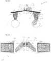
- Figure 4schematically shows an apparatus in the form of glasses/goggles with support members/arms 418 for holding the apparatus in place on a user's head.
- the detector 413is not disposed on the light guides.
- a reflector element 417such as a mirror or hot mirror configured to reflect infrared light, is provided e.g. on in the light guide, namely an inner/lower surface of the lower light guide. It is to be appreciated that the reflector element could be located almost anywhere in front of the eye, even on an opposite side of the light guide stack.
- the reflectoris configured to further reflect 419 the reflected gaze tracking beam to a detector 413, thereby providing increased flexibility as to the location of the detector.
- the detectoris disposed on a part of a housing of the apparatus such as support arm 418.
- the reflector 417may be further configured so as to provide optical power so as to focus the reflected infrared gaze tracking probe beam 214 towards the detector 413.
- FIG. 5Aschematically illustrates an example of an apparatus 500 comprising a combined/highly integrated visible and infrared light source 512 which may be used as a laser projector engine.
- a laser diode 521generates infrared light which is focused by lens 522 into a non-linear crystal 523, such as periodically poled lithium niobate (PPLN), comprising a surface bragg grating whereby the infrared light is converted into red, green and blue visible wavelengths.
- PPLNperiodically poled lithium niobate
- a conventional laser projection enginewould typically block such non-converted infrared light deeming it to be an undesired noise signal.
- the light source 512provides the simultaneous generation of both visible light as well as infrared light that can be incident to a light modulator 501, under control of a controller 515, so as to sequentially generate an image display beam and a gaze tracking probe beam from the incident visible and infrared beams respectively.
- a selectively controllable filter or shuttermay be used to selectively filter/block IR light when the image display beam is being generated and likewise selectively filter/block visible light when the gaze tracking probe beam is being generated.
- the light modulator 501comprises a two axis scanning mirror which can be used to impart an image to the visible light from the light source to generate the image display beam. Also, the light modulator can be used to impart a pattern on the infrared light from the light source to generate the gaze tracking probe beam.
- Figure 5Bschematically illustrates an apparatus 530 with an alternative light source 512 and an alternative light modulator 501.
- the light source 512is configured to independently and separately generate visible light (and/or sub component colour channels thereof) and infrared light.
- the light source 512may corresponds to one or more separate light sources, e.g. LEDs, such as: red, green, blue and infrared LEDs which are independently operable under control of a controller 515. Light from the LEDs is directed to a reflective microdisplay 531 via beam splitter 532.
- the modulated/modified light reflected from the microdisplayis then guided to a prism 533 and reflected therefrom to an in-coupling diffractive element area 507 of a light guide 506 to be out-coupled to a user's eye 110 via out-coupling diffractive element area 508.
- a detector 513is provided that is configured to detect the out-coupled light which is reflected from the user's eye.
- modulerefers to a unit or apparatus that excludes certain parts/components that would be added by an end manufacturer or a user.
- the apparatusmay be provided as a device, wherein a device is configured for at least one of portable use, wearable use and head mountable use.
- the devicemay also be configured to provide functionality in addition to display and gaze tracking.
- the devicemay additionally be configured to provide one or more of: audio/text/video communication functions (e.g. tele-communication, video-communication, and/or text transmission (Short Message Service (SMS)/ Multimedia Message Service (MMS)/emailing) functions), interactive/non-interactive viewing functions (e.g. web-browsing, navigation, TV/program viewing functions), music recording/playing functions (e.g.
- audio/text/video communication functionse.g. tele-communication, video-communication, and/or text transmission (Short Message Service (SMS)/ Multimedia Message Service (MMS)/emailing) functions
- interactive/non-interactive viewing functionse.g. web-browsing, navigation, TV/program viewing functions
- music recording/playing functions
- MP3Moving Picture Experts Group-1 Audio Layer 3
- FM3frequency modulation/amplitude modulation
- the apparatusmay be a part of a NED device, for example, glasses or goggles. It should be understood, however, that glasses or goggles are merely illustrative of an NED device that would benefit from examples of implementations of the present disclosure and, therefore, should not be taken to limit the scope of the present disclosure to the same.
- the apparatusmay take other forms such as a visor or helmet or may be implemented in other electronic devices not least hand devices, or portable devices.
- circuitryrefers to all of the following:
- circuitrywould also cover an implementation of merely a processor (or multiple processors) or portion of a processor and its (or their) accompanying software and/or firmware.
- wordingsuch as 'couple', 'connect' and 'communication' and their derivatives mean operationally coupled/connected/in communication. It should be appreciated that any number or combination of intervening components can exist (including no intervening components).
- references to "a/an/the” [feature, element, component, means ...]are to be interpreted as “at least one” [feature, element, component, means ...] unless explicitly stated otherwise.
Landscapes
- Physics & Mathematics (AREA)
- Engineering & Computer Science (AREA)
- General Physics & Mathematics (AREA)
- Health & Medical Sciences (AREA)
- Optics & Photonics (AREA)
- Life Sciences & Earth Sciences (AREA)
- Multimedia (AREA)
- Signal Processing (AREA)
- Human Computer Interaction (AREA)
- Ophthalmology & Optometry (AREA)
- General Health & Medical Sciences (AREA)
- Medical Informatics (AREA)
- Biomedical Technology (AREA)
- Heart & Thoracic Surgery (AREA)
- Biophysics (AREA)
- Molecular Biology (AREA)
- Surgery (AREA)
- Animal Behavior & Ethology (AREA)
- Public Health (AREA)
- Veterinary Medicine (AREA)
- Toxicology (AREA)
- Theoretical Computer Science (AREA)
- Optical Modulation, Optical Deflection, Nonlinear Optics, Optical Demodulation, Optical Logic Elements (AREA)
Description
- Examples of the present disclosure relate to an apparatus for a near-eye display. Some examples, though without prejudice to the foregoing, relate to an apparatus for providing gaze tracking in a near-eye display.
- Gaze tracking, namely the process of determining a point of gaze of a user's eye so as to determine a line of sight associated with the user's eye or to determine where the user is looking (and thus determining what the user is looking at), typically relies on capturing video images from a user's eye(s). Such video based gaze tracking typically uses infrared (IR) LEDs or infrared lasers for illuminating the eye and detecting reflections/glints of the infrared light from the eye (e.g. its cornea/surface). A determination of a user's gaze may be calculated based on the detected IR reflections and detected eye features such as detected pupil position. Conventional near-eye displays with integrated gaze tracking functionality systems are not always optimal, not least for example in view of the additional components as well as increased complexity, size and weight necessary to incorporate both gaze tracking functionality as well as display functionality in a near-eye display.
WO 2007/085682 A1 discloses two collimated light beams directed towards an eye to provide two reflection spots. The collimated light beams are provided by a diffractive beam expander. The reflection spots and the pupil of the eye are monitored by an imaging unit. The collimated beams are at different angles with respect to the imaging unit. The gaze direction is determined based on said angles, the positions of the reflections spots, and the position of the pupil. Thanks to the use of two collimated beams, the detected gaze direction is substantially independent of the size of the eye (100), independent of the lateral position of the eye, and independent of the distance between the imaging unit and the eye. The detected gaze angle may be used for selecting between options displayed by a virtual display.WO 2013/049012 A1 discloses technology for an integrated eye tracking and display system for a see-through, near-eye, mixed reality display device. Image data and IR illumination for eye tracking are optically coupled into a respective see-through, planar waveguide positioned to be seen through by each eye in a respective display optical system of the display device. The respective planar waveguide comprises one or more wavelength selective filters positioned to be co-axial with an optical axis of the respective display optical system. The wavelength selective filters direct IR and visible illumination out of the planar waveguide in the direction of the respective eye and direct IR reflections, including reflections from the eye, into the planar waveguide. The reflections are optically coupled out of the waveguide to an IR sensor which generates eye tracking data based on the reflections.- The listing or discussion of any prior-published document or any background in this specification should not necessarily be taken as an acknowledgement that the document or background is part of the state of the art or is common general knowledge. One or more aspects/examples of the present disclosure may or may not address one or more of the background issues.
- According to the present invention there is provided an apparatus as claimed in claim 1.
- Certain examples of the apparatus may be provided as a module for a device or as a device itself. The device may be configured for at least one of: portable use, wearable use, head mountable use. Certain examples of the apparatus are configured for use with a Near Eye Display (NED) for providing both display and gaze tracking functionality.
- The examples of the present disclosure and the accompanying claims may be suitably combined in any manner apparent to one of ordinary skill in the art.
- For a better understanding of various examples of the present disclosure that are useful for understanding the detailed description and certain embodiments of the invention, reference will now be made by way of example only to the accompanying drawings in which:
Figure 1 schematically illustrates an example of an apparatus according to the present disclosure;Figure 2 schematically illustrates a further example of an apparatus according to the present disclosure;Figure 3 schematically illustrates an example of diffractive light guides suitable for use with examples of the present disclosure;Figure 4 schematically illustrates a yet further example of an apparatus according to the present disclosure; andFigures 5A and5B schematically illustrate examples of light modulators suitable for use with examples of the present disclosure.- Examples of apparatuses according to the present disclosure will now be described with reference to the Figures. Similar reference numerals are used in the Figures to designate similar features. For clarity, all reference numerals are not necessarily displayed in all figures.
Figure 1 schematically illustrates a block diagram of anapparatus 100 according to an example of the present disclosure.Figure 1 focuses on the functional components necessary for describing the operation of the apparatus.- The
apparatus 100 comprises a light modulator 101 configured to receive light of a first range ofwavelengths 102, and generate animage beam 103 therefrom. The light modulator 101 is further configured so as to receive light of a second range ofwavelengths 104 and generate aprobe beam 105 therefrom. - The
apparatus 100 further comprises one or more light guides 106 comprising one or more in-couplingdiffractive element areas 107, and one or more out-couplingdiffractive element areas 108. The one or more in-couplingdiffractive element areas 107 are configured to receive and in-couple theimage beam 103 and theprobe beam 105 into the one or more light guides 106. The one or more out-couplingdiffractive element areas 108 are configured to out-couple, from the one or more light guides 106: - the
image beam 109 to a user'seye 110 for user viewing, and - the probe beam 111 to the user's
eye 110 for detection of reflection therefrom. - Each of the components described above may be one or more of any element, device, mechanism or means configured to perform the corresponding functions of the respective components as described in greater detail below. The component blocks of
Figure 1 are functional and the functions described may or may not be performed by a single physical entity for example the light modulator 101 may correspond to an assembly/arrangement of components, not least for example as shown inFigures 5A orFigure 5B . Accordingly, the blocks support: combinations of means for performing the specified functions. - The light modulator 101 may comprise a light modulating/modifying means configured to modulate/modify the
incident light collimated beams - The
image beam 103 may comprise a collimated beam of light that may be expanded and guided to user'seye 110 for viewing and perceiving the image which is imparted to thelight 102 that forms theimage beam 103 by the light modulator 101. Where thelight 102 of the first range of wavelengths comprises one or more colour channels of visible light, e.g. one or more of red (R), green (G) and blue (B), theimage beam 103 may correspondingly comprise light within the visible range of the electromagnetic spectrum, e.g. one or more of R, G and B. In certain examples, one or more image beams may be generated corresponding to the image in differing colour channels, e.g. one or more of R, G and B, from light received in the respective colour channels. - The
probe beam 105 may comprise a collimated beam of light that may be expanded and guided to user'seye 110 for reflection therefrom. In certain examples (seeFigure 2 ), such reflection is detected and used in part to determine a gaze or direction of view of theeye 110. The light modulator 101 may impart a variable pattern, image, shape or size tolight 104 that forms theprobe beam 105. Where the light of the second range of wavelengths comprises infrared light the probe beam may correspondingly comprise light within the infrared part of the electromagnetic spectrum. - The one or more light guides 106 may comprise light guiding means comprising one or more means for diffracting beams into and out of the light guide, for example a diffractive optical element. The light guides may, for example, be a one or more substantially planar substrates comprising one or more areas or diffractive elements / gratings / grooves that are disposed on lower or upper surfaces of the substrate or even located internally of the substrate. The light guide may be an exit pupil expander configured to expand an incident beam of
light - Certain examples of the apparatus: may reduce the complexity of a combined display and gaze tracking device, may provide improved integration and require fewer components, and may thus also reduce the weight and size of the apparatus by enabling the sharing/reutilisation of various components. This may enable the provision of a miniaturised and efficient apparatus for integrated NED and Gaze tracking. For example, the light modulator 101 which generates the
image beam 103 is also used to generate theprobe beam 105. In other examples, a light source for emitting the light for theimage beam 103 is also used to generate the light for theprobe beam 105. - The use of the light modulator 101 to generate the
probe beam 105 may enable a pattern, shape or size of the probe beam to be dynamically varied. Such control of the probe beam may enable the creation of complex variable shapes, sizes, patterns/images of the probe beam. Moreover, the probe beam could be dynamically adjusted during use so as to achieve optimal detection and measurement results thereby enabling more robust gaze tracking as well as simpler gaze tracking calibration. - Furthermore, certain examples (e.g.
figure 1 ) provide the ability to share/utilise one or more of in-couplingdiffractive elements 107 and/or one or more of the out-couplingdiffractive elements 108 to in-couple and/or out-couple both theimage beam 103 and theprobe beam 105 and may thereby reduce the number of optical components and the complexity of the arrangements of such components that may otherwise have been required to direct each of the image beam and probe beam separately and independently. - Furthermore, embodiments of the invention (see e.g.
Figure 5A ) enable the use of a combinedlight source 512 which simultaneously generates both the light 102 for theimage beam 103 as well aslight 104 for theprobe beam 105 and may thereby reduce the number of components (and thus the weight, size and complexity) of the apparatus. - In the example of
Figure 1 , the light guide 106 comprises a substrate of an optical material having first and second opposing surfaces. The substrate comprises an area of in-couplingdiffractive elements 107 and an area of out-couplingdiffractive elements 108 which may be laterally spaced apart from one another on the planar substrate for example at either end of the substrate. The in-coupling diffractive element area is configured to receive one or more input optical beams, i.e. either the image beam 103 ("image display beam") or the probe beam 105 ("gaze tracking probe beam"), and diffract the input optical beam substantially within the first and second surfaces to provide a diffracted optical beam within the substrate which is coupled via total internal reflection to the out-couplingdiffractive element area 108. The out-coupling diffractive element area is configured to further diffract the diffracted optical beam out of the substrate to provide an output optical beam, namely an output of theimage display beam 109 or the output gaze tracking probe beam 111. - The out-
coupling diffractive element 108 may be configured so as to not only just output the diffracted optical beam from the substrate but also to expand the diffracted optical beam in one direction. Further diffractive elements may be provided (for example 316a as shown inFigure 3 ) for expanding the diffracted optical beam in another direction so as to provide anoutput beam 109, 111 that can be expanded beam in two directions. - In certain examples, the in-coupling and out-coupling elements may be based on other optical methods than diffraction gratings and groves, for example volume holograms or gratings, or semi-transparent mirror structures.
- The apparatus of
Figure 1 shows a schematic illustration of a monocular apparatus. However, it is to be appreciated that the apparatus could be configured in a binocular form. Such a binocular form could correspond to providing twoapparatuses 100 one for each of the user's eyes. For example, providingapparatus 100 shown inFigure 1 for a user's right eye and a mirror image version of theapparatus 100 for the user's left eye (similar to that ofFigure 2 ). As an alternative to using two such laterally adjacent light guides, a single light guide could be provided having an in-coupling diffractive element area between two out-coupling diffractive element areas located at either end of the light guide wherein the in-coupling diffractive element area is configured to provide two diffracted input optical beams, one coupled to one of the out-coupling diffractive element areas, for example at a left hand end of the light guide, and the other diffracted input optical beam coupled to the other of the out-coupling diffractive element areas at the other end, e.g. a right hand end of the light guide. Figure 1 shows a single diffractive light guide 106 provided with one in-couplingdiffractive element area 107 which is configured to diffract light at the first range of wavelengths (e.g. in the visible part of the electromagnetic spectrum) as well as light at the second range of wavelengths (e.g. the IR part of the electromagnetic spectrum). Thus, thediffractive element area 107 may be configured to in-couple both the image display beam as well as the gaze tracking probe beam, i.e. the diffractive element may be configured so as to diffract (or at least have an acceptable efficiency for diffracting) each of infrared, red, green and blue colour channels regions of the electromagnetic spectrum or to diffract a portion of a colour channel. It should be appreciated that other colour channels / apportionment of the visible spectrum may also be envisaged. Likewise, the single out-coupling diffractive element 108 may be similarly configured to diffract and out-couple a corresponding wide range of wavelengths.- As an alternative to using a single in-coupling diffractive element area for in-coupling a wide range of wavelengths of input beams 103, 105, a plurality of in-coupling diffractive element areas could be provided on a light guide, each area spatially distinct from another and each being configured and optimised to diffract a particular/narrower range of wavelengths, for example one or more colour channels, infrared, red, green or blue, to provide one or more diffractive optical beams of such wavelengths of light within the substrate for out-coupling from the substrate by one or more out-coupling diffractive element areas.
- Likewise, a plurality of out-coupling diffractive elements could be provided on the light guide each configured and optimised to diffract a particular narrow range of wavelengths of light and out-couple them from the light guide.
- Yet further alternatively, instead of having a single light guide (with one or more in-coupling diffractive element areas and one or more out-coupling diffractive element areas) a plurality of light guides may be provided, e.g. vertically aligned and stacked on top of each other. Each of the stacked light guides could be provided with one or more in/out-coupling diffractive element areas configured and optimised to in-couple and out-couple one or more particular colour channels. Thus, it is to be appreciated that a variety of possible combinations of: numbers of in- and out-coupling diffractive element areas per light guide, as well as number of stacked light guides are envisaged.
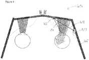
Figure 2 shows anapparatus 200 in a binocular form comprising a right hand side set of stacked light guides 106a and 106a' along with a left hand side set of stacked light guides 106b and 106b'. For the sake of simplicity, the below discussion focuses just on the right hand side components of the apparatus. It is to be appreciated that similar components may be provided on the left hand side of the apparatus (with equivalent reference numerals but designated with a "b" instead of "a").- Of the two stacked light guides 106a and 106a', one is configured and optimised to in-couple, expand and out-couple visible light for example in the green and blue parts of the spectrum, whereas the other light guide is configured and optimised to in-couple, expand and out-couple infrared light and red light.
- It is to be appreciated that other permutations may readily be envisaged, not least for example a plurality of stacked light guides each optimised for one of: blue, green, red and infrared respectively, or, similarly to
Figure 1 , a single light guide may be provided for in- and out-coupling all of IR, R, G and B wavelengths of light beams. Also, one light guide optimised for RGB could be provided with another optimised for IR. Such an IR optimised light guide could be made to be thinner than an RGB light guide. It could further be configured for other integrated uses, such as: being used as a protective element, or a capacitive measurement surface for face/eye movement detection as well as an LC shutter and hot mirror as discussed in further details below. - A single light source 212a emits light 102, 104 for both the image display beam 103 (i.e. visible light) as well as light for the gaze
tracking probe beam 105, (i.e. infrared light). Such a light source generating simultaneously both visible light and infrared light may correspond to a laser crystal on silicone based light source as discussed further with respect toFigure 5A . Alternatively, instead of having a light source that generates simultaneously both the visible and infrared light, separate light sources may be provided which generate independently visible light and infrared, for example separate light sources configured to emit each of visible light and infrared light, not least for example separate red, green, blue and infrared LEDs positioned adjacent to one another which can be separately and independently controlled/switched on such that only visible light is emitted and received by the light modulator when generating the display imaging and likewise only infrared light is emitted and received at the light modulator when generating the gaze tracking probe beam. - The light source 212a generates the light of the first range of
wavelengths 102 and also generates the light of the second range ofwavelengths 104, each of which are incident to a light modulator 201a which generates animage display beam 103 and a gazetracking probe beam 105 from such incident light respectively. Additional optics, e.g. lenses, mirrors or MEM system may be provided as well as other mechanisms for focusing, collimating the source of light into beams of light that may further be scanned / rastered into the in-coupling diffractive element. - The image display beam from the light modulator 201a is incident to a first in-coupling diffractive element area 107a and in-coupled into the first light guide 106a and then out-coupled via out-coupling diffractive element 108a (propagating through the underlying light guide 106a') so as to be directed towards a user's
eye 110. The first light guide may be configured and optimised so as to in-couple, expand and out-couple light of the image display beam in green and blue parts of the visible spectrum. The further light guide 106a' may be provided with an in-coupling diffractive element area 107a' and an out-coupling diffractive element area 108a' configured and optimised to in-couple, expand and diffract out visible light of the image display beam in the red part of the spectrum. The second light guide 106a' may further be configured to in-couple, expand and out-couple infrared light to provide an output gaze tracking probe beam 111 which is incident to the user's eye to be reflected therefrom. - A
detector 213, such as an IR detector/sensor or camera, may be provided to detectreflections 214 of the gaze tracking probe beam from the user's eye, i.e. images/video of the user's eye in IR. The detection and measurement ofsuch reflections 214 of the infrared gaze tracking probe beam may be used in part by a controller 215 to calculate and determine a user's gaze. - In some examples, other features of the eye are also measured and captured, for example related to a location of the user's eye pupil. In some examples, the IR detector / eye camera is used to capture and measure not only the reference reflections/glints 214 but is also used to capture and measure a location of the eye pupil. A determination may be made of the detected location of the
reference reflection 214 relative to the detected location of the pupil. Differences of the relative movement between the pupil and thereference reflections 214 can be used for detecting changes in the gaze direction. - The determination of the gaze may also be dependent on the generated gaze tracking probe beam, i.e. taking into account one or more characteristics of the generated infrared probe beam outputted such as its initial shape, size and intensity prior to being reflected from the user's eye as compared to the shape, size and intensity of the detected reflected gaze tracking probe beam.
- Implementation of the controller 215 can be in hardware alone (e.g. circuitry such as processing circuitry comprising one or more processors and memory circuitry comprising one or more memory elements), have certain aspects in software including firmware alone or can be a combination of hardware and software (including firmware).
- The controller 215 may be used to control one or more of the light source 212a and the light modulator 201a so as to control each of the image display beam and the gaze tracking probe beam. The generated gaze tracking probe beam may be modified, e.g. its size or shape or intensity, depended upon the detected reflected gaze tracking probe beam. Such feedback from the detection of the reflected gaze tracking probe beam can assist in the calibration of the apparatus and enable for the gaze tracking probe beam's pattern, shape or size to be optimised for the prevailing circumstances of use.
- Whilst
Figure 2 shows asingle detector 213 for detecting the gaze of one eye, i.e. the user's right eye, the arrangement could be modified to, alternatively or additionally, determine the gaze of the user's other eye. WhilstFigure 2 shows asingle detector 213 for detecting the gaze of one eye, i.e. the user's right eye, the arrangement could be modified to determine the gaze of the eye using two or more detectors. WhilstFigure 2 shows two light sources 212a and 212b, and two modulators 201a and 201b, a single light source and/or a single light modulator could be provided for generate image display and probe beams that are incident to each of the two in-coupling diffractive element areas 107a and 107b. - In the apparatus of
Figure 2 , where a combined visible and infrared light source is used, i.e. that simultaneously generates both visible and infrared light (as opposed to separately and independently generating visible and IR light such that the emission of visible and IR light can be separately and independently controlled), the apparatus may further comprise a selectively controllable filter to selectively filter out one of: the visible light (or a sub colour channel thereof) or the infrared light. - In some examples, e.g. where the IR optimised light guide is below (and disposed closer to the eye than) the RGB optimised light guide, a passive IR pass filter could be placed between the in-coupling area of the RGB optimised light guide and the in-coupling area of the IR optimised light guide, e.g. so as to reduce in-coupling of RGB light to the IR light guide. Alternatively, in other examples, e.g. where the RGB optimised light guide is below (and placed closer to the eye than) the IR optimised light guide, an IR blocking filter could be placed between the respective in-coupling areas, e.g. so as to reduce in-coupling of IR light to the RBG light guide.
- In some examples a Liquid Crystal (LC) shutter could be placed between the light guides and the outside environment/world/reality. For example the LC shutter could form part of a selectively transparent part of the external housing of the apparatus which is configured to selectively enable a real world view though the apparatus. Adjusting the shutter's transmissivity would control how much ambient light gets to the eye through the shutter and through the transparent light guides. The LC shutter could, in some examples, be integrated into an IR optimised light guide, in which case such a light guide may be placed between the RGB optimised light guide(s) and the outside environment/world/reality so that it would not block the RGB light from the light guide reaching the eye.
- In some examples, the light guide 106a' which in-couples, expands and out-couples the infrared gaze tracking probe beam may be configured so as to selectively filter the transmission of infrared light therethrough. The light guide 106a' may be configured to act as a liquid crystal shutter that can selectively block the transmission of infrared light therethrough whilst still permitting the transmission of visible light therethrough.
- When an image display beam is being generated and outputted, a selectively controllable filter may be used to block infrared light such that only visible light is incident to the user's eye during periods of outputting the image display beam output for user viewing. Likewise, in other examples, visible light may be selectively filtered / blocked / switched off such that only infrared gaze tracking light probe beam may be generated and incident to the user's eye when outputting an infrared gaze tracking probe beam.
Figure 3 schematically illustrates an example of light guides 306a and 306b suitable for use with examples of the present disclosure. For example, the light guides 306a and 306b may be configured for use as light guides 106a and 106b, or 106a' and 106b' ofFigure 2 .- The light guide 306a comprises in-coupling diffractive area 307a which in-couples an input beam 305a to the substrate, which beam is then expanded via diffractive element area 316a in a y direction and then expanded in an x direction and out-coupled out of the light guide via an out-coupling diffractive element 308a so as to produce output beam 311a. The input optical beam 305a may correspond to an image display beam (or a component of the image display beam such as a red, green or blue component thereof) or an infrared gaze tracking probe beam.
- In the apparatus of
Figure 2 , the reflected gazetracking probe beam 214 needs to propagate through each of the stacked light guides 106a' and 106a to reach the detector for detection.Figure 4 schematically shows anapparatus 400 that avoids such issues. Figure 4 schematically shows an apparatus in the form of glasses/goggles with support members/arms 418 for holding the apparatus in place on a user's head. In this example, thedetector 413 is not disposed on the light guides. Instead, areflector element 417, such as a mirror or hot mirror configured to reflect infrared light, is provided e.g. on in the light guide, namely an inner/lower surface of the lower light guide. It is to be appreciated that the reflector element could be located almost anywhere in front of the eye, even on an opposite side of the light guide stack.- The reflector is configured to further reflect 419 the reflected gaze tracking beam to a
detector 413, thereby providing increased flexibility as to the location of the detector. In this example, the detector is disposed on a part of a housing of the apparatus such as support arm 418. Thereflector 417 may be further configured so as to provide optical power so as to focus the reflected infrared gazetracking probe beam 214 towards thedetector 413. Figure 5A schematically illustrates an example of anapparatus 500 comprising a combined/highly integrated visible and infraredlight source 512 which may be used as a laser projector engine. Alaser diode 521 generates infrared light which is focused bylens 522 into anon-linear crystal 523, such as periodically poled lithium niobate (PPLN), comprising a surface bragg grating whereby the infrared light is converted into red, green and blue visible wavelengths. However, some infrared light will pass through the non-linear crystal without undergoing such conversion. A conventional laser projection engine would typically block such non-converted infrared light deeming it to be an undesired noise signal. However, such non-converted infrared light may advantageously be used in examples of the present application as a source of infrared illumination. Thus, thelight source 512 provides the simultaneous generation of both visible light as well as infrared light that can be incident to alight modulator 501, under control of a controller 515, so as to sequentially generate an image display beam and a gaze tracking probe beam from the incident visible and infrared beams respectively. A selectively controllable filter or shutter may be used to selectively filter/block IR light when the image display beam is being generated and likewise selectively filter/block visible light when the gaze tracking probe beam is being generated.- The
light modulator 501 comprises a two axis scanning mirror which can be used to impart an image to the visible light from the light source to generate the image display beam. Also, the light modulator can be used to impart a pattern on the infrared light from the light source to generate the gaze tracking probe beam. Figure 5B schematically illustrates anapparatus 530 with an alternativelight source 512 and an alternativelight modulator 501. Thelight source 512 is configured to independently and separately generate visible light (and/or sub component colour channels thereof) and infrared light. Thelight source 512 may corresponds to one or more separate light sources, e.g. LEDs, such as: red, green, blue and infrared LEDs which are independently operable under control of a controller 515. Light from the LEDs is directed to areflective microdisplay 531 via beam splitter 532. The modulated/modified light reflected from the microdisplay is then guided to aprism 533 and reflected therefrom to an in-couplingdiffractive element area 507 of alight guide 506 to be out-coupled to a user'seye 110 via out-couplingdiffractive element area 508. Adetector 513 is provided that is configured to detect the out-coupled light which is reflected from the user's eye.- The apparatuses as variously described above may be provided in a module. As used here 'module' refers to a unit or apparatus that excludes certain parts/components that would be added by an end manufacturer or a user.
- In certain examples, the apparatus may be provided as a device, wherein a device is configured for at least one of portable use, wearable use and head mountable use. The device may also be configured to provide functionality in addition to display and gaze tracking. For example, the device may additionally be configured to provide one or more of: audio/text/video communication functions (e.g. tele-communication, video-communication, and/or text transmission (Short Message Service (SMS)/ Multimedia Message Service (MMS)/emailing) functions), interactive/non-interactive viewing functions (e.g. web-browsing, navigation, TV/program viewing functions), music recording/playing functions (e.g. Moving Picture Experts Group-1 Audio Layer 3 (MP3) or other format and/or (frequency modulation/amplitude modulation) radio broadcast recording/playing), downloading/sending of data functions, image capture function (e.g. using a (e.g. in-built) digital camera), and gaming functions.
- The apparatus may be a part of a NED device, for example, glasses or goggles. It should be understood, however, that glasses or goggles are merely illustrative of an NED device that would benefit from examples of implementations of the present disclosure and, therefore, should not be taken to limit the scope of the present disclosure to the same. For example the apparatus may take other forms such as a visor or helmet or may be implemented in other electronic devices not least hand devices, or portable devices.
- Although examples of the apparatus have been described above in terms of comprising various components, it should be understood that the components may be embodied as or otherwise controlled by a corresponding processing element, processor or circuitry of the apparatus.
- As used in this application, the term 'circuitry' refers to all of the following:
- (a) hardware-only circuit implementations (such as implementations in only analogue and/or digital circuitry) and
- (b) to combinations of circuits and software (and/or firmware), such as (as applicable): (i) to a combination of processor(s) or (ii) to portions of processor(s)/software (including digital signal processor(s)), software, and memory(ies) that work together to cause an apparatus, such as a mobile phone or server, to perform various functions) and
- (c) to circuits, such as a microprocessor(s) or a portion of a microprocessor(s), that require software or firmware for operation, even if the software or firmware is not physically present.
- This definition of 'circuitry' applies to all uses of this term in this application, including in any claims. As a further example, as used in this application, the term "circuitry" would also cover an implementation of merely a processor (or multiple processors) or portion of a processor and its (or their) accompanying software and/or firmware.
- Features described in the preceding description may be used in combinations other than the combinations explicitly described.
- Although functions have been described with reference to certain features, those functions may be performable by other features whether described or not. Although features have been described with reference to certain examples, those features may also be present in other examples whether described or not. Although various examples of the present disclosure have been described in the preceding paragraphs, it should be appreciated that modifications to the examples given can be made without departing from the scope of the invention as set out in the claims.
- The term 'comprise' is used in this document with an inclusive not an exclusive meaning. That is any reference to X comprising Y indicates that X may comprise only one Y or may comprise more than one Y. If it is intended to use 'comprise' with an exclusive meaning then it will be made clear in the context by referring to "comprising only one ..." or by using "consisting".
- In this description, wording such as 'couple', 'connect' and 'communication' and their derivatives mean operationally coupled/connected/in communication. It should be appreciated that any number or combination of intervening components can exist (including no intervening components).
- In this description, reference has been made to various examples. The description of features or functions in relation to an example indicates that those features or functions are present in that example. The use of the term 'example' or 'for example' or 'may' in the text denotes, whether explicitly stated or not, that such features or functions are present in at least the described example, whether described as an example or not, and that they can be, but are not necessarily, present in some or all other examples. Thus 'example', 'for example' or 'may' refers to a particular instance in a class of examples. A property of the instance can be a property of only that instance or a property of the class or a property of a sub-class of the class that includes some but not all of the instances in the class.
- In this description, references to "a/an/the" [feature, element, component, means ...] are to be interpreted as "at least one" [feature, element, component, means ...] unless explicitly stated otherwise.
- The above description describes some examples of the present disclosure however those of ordinary skill in the art will be aware of possible alternative structures and method features which offer equivalent functionality to the specific examples of such structures and features described herein above and which for the sake of brevity and clarity have been omitted from the above description. Nonetheless, the above description should be read as implicitly including reference to such alternative structures and method features which provide equivalent functionality unless such alternative structures or method features are explicitly excluded in the above description of the examples of the present disclosure.
Claims (13)
- An apparatus (100) for providing gaze tracking in a near-eye display comprising:a light source (512) configured to generate light of a first range of wavelengths (102) and light of a second range of wavelengths (104);a light modulator (101) configured to receive light of the first range of wavelengths (102) from the light source and modify the light of the first range of wavelengths (102) so as to impart an image thereon and generate an image beam (103, 109) therefrom, wherein the light modulator is further configured to receive light of the second range of wavelengths (102) from the light source and modify the light of the second range of wavelengths (104) so as to impart a pattern thereon and generate a probe beam (105, 111) therefrom;one or more light guides (106) comprising:one or more in-coupling diffractive element areas (107), andone or more out-coupling diffractive element areas (108);wherein the one or more in-coupling diffractive element areas are configured to receive and in-couple the image beam and the probe beam into the one or more light guides;wherein the one or more out-coupling diffractive element areas are configured to out-couple, from the one or more light guides:the image beam to a user's eye (110) for user viewing, andthe probe beam to the user's eye for detection of reflectiontherefrom;the apparatus further comprising:a detector (213) configured to detect reflections (214) of the probe beam (105, 111); anda controller (215) configured to control the light modulator (101) to modify the pattern of the probe beam (105, 111) dependent upon the detection of the reflected probe beam (214).
- An apparatus (100) as claimed in claim 1, wherein the light modulator (101) is further configured to:control a pattern, shape and/or size of the probe beam; and/ordynamically vary a pattern of the probe beam.
- An apparatus (100) as claimed in any one or more of the previous claims, further comprising a reflector (417) configured to further reflect the reflected probe beam (214) to the detector.
- An apparatus (100) as claimed in any one or more of the previous claims wherein the controller (215) is configured to determine a user's gaze based on the detected reflected probe beam (214).
- An apparatus (100) as claimed in any one or more of the previous claims, wherein the light of the first range of wavelengths (102) comprises visible light and the light of the second range of wavelengths (104) comprises Infrared light.
- An apparatus (100) as claimed in any one or more of the previous claims, in which the light source (512) is configured to generate simultaneously the light of the first range of wavelengths (102) and the light of the second range of wavelengths (104).
- An apparatus (100) as claimed in any one or more of the previous claims, further comprising a selectively controllable filter to selectively filter one of: the light of the first range of wavelengths (102) and the light of the second range of wavelengths (104).
- An apparatus (100) as claimed in any one or more of the previous claims, in which the light source (212a) is configured to generate sequentially the light of the first range of wavelengths (102) and the light of the second range of wavelengths (104).
- An apparatus (100) as claimed in any one or more of the previous claims, wherein the one or more in-coupling diffractive element areas (107) and one or more out-coupling diffractive element areas (108) are comprised in a single light guide (106).
- An apparatus (100) as claimed in any one or more of the previous claims, wherein the one or more light guides (106) is configured as an exit pupil expander.
- An apparatus (100) as claimed in any one or more of the previous claims, wherein the apparatus is configured for use as a near eye display and a gaze tracker.
- A module comprising the apparatus (100) of any one or more of previous claims.
- A device comprising the apparatus (100) of any one or more of previous claims 1 to 11 or the module of claim 12, wherein the device is configured for at least one at least one of:
portable use, wearable use, head mountable use, wireless communications.
Priority Applications (8)
| Application Number | Priority Date | Filing Date | Title |
|---|---|---|---|
| EP15156666.8AEP3062142B1 (en) | 2015-02-26 | 2015-02-26 | Apparatus for a near-eye display |
| JP2017542913AJP6573139B2 (en) | 2015-02-26 | 2016-02-05 | Near-eye display device |
| US15/552,897US10878235B2 (en) | 2015-02-26 | 2016-02-05 | Apparatus for a near-eye display |
| PCT/FI2016/050072WO2016135375A1 (en) | 2015-02-26 | 2016-02-05 | Apparatus for a near-eye display |
| JP2019140435AJP6853310B2 (en) | 2015-02-26 | 2019-07-31 | Near-eye display device |
| US17/105,848US11347960B2 (en) | 2015-02-26 | 2020-11-27 | Apparatus for a near-eye display |
| US17/713,505US11756335B2 (en) | 2015-02-26 | 2022-04-05 | Apparatus for a near-eye display |
| US18/348,732US20230351808A1 (en) | 2015-02-26 | 2023-07-07 | Apparatus for a near-eye display |
Applications Claiming Priority (1)
| Application Number | Priority Date | Filing Date | Title |
|---|---|---|---|
| EP15156666.8AEP3062142B1 (en) | 2015-02-26 | 2015-02-26 | Apparatus for a near-eye display |
Publications (2)
| Publication Number | Publication Date |
|---|---|
| EP3062142A1 EP3062142A1 (en) | 2016-08-31 |
| EP3062142B1true EP3062142B1 (en) | 2018-10-03 |
Family
ID=52630215
Family Applications (1)
| Application Number | Title | Priority Date | Filing Date |
|---|---|---|---|
| EP15156666.8AActiveEP3062142B1 (en) | 2015-02-26 | 2015-02-26 | Apparatus for a near-eye display |
Country Status (4)
| Country | Link |
|---|---|
| US (4) | US10878235B2 (en) |
| EP (1) | EP3062142B1 (en) |
| JP (2) | JP6573139B2 (en) |
| WO (1) | WO2016135375A1 (en) |
Families Citing this family (82)
| Publication number | Priority date | Publication date | Assignee | Title |
|---|---|---|---|---|
| CN112925100B (en) | 2014-09-29 | 2023-10-31 | 奇跃公司 | Optical system |
| NZ773836A (en) | 2015-03-16 | 2022-07-01 | Magic Leap Inc | Methods and systems for diagnosing and treating health ailments |
| EP3308220B1 (en) | 2015-06-15 | 2020-11-18 | Magic Leap, Inc. | Display system with optical elements for in-coupling multiplexed light streams |
| US10459305B2 (en) | 2015-08-03 | 2019-10-29 | Facebook Technologies, Llc | Time-domain adjustment of phase retardation in a liquid crystal grating for a color display |
| US9989765B2 (en) | 2015-08-03 | 2018-06-05 | Oculus Vr, Llc | Tile array for near-ocular display |
| US10297180B2 (en) | 2015-08-03 | 2019-05-21 | Facebook Technologies, Llc | Compensation of chromatic dispersion in a tunable beam steering device for improved display |
| US10552676B2 (en) | 2015-08-03 | 2020-02-04 | Facebook Technologies, Llc | Methods and devices for eye tracking based on depth sensing |
| US10338451B2 (en) | 2015-08-03 | 2019-07-02 | Facebook Technologies, Llc | Devices and methods for removing zeroth order leakage in beam steering devices |
| HK1256792A1 (en) | 2015-09-23 | 2019-10-04 | Magic Leap, Inc. | Eye imaging with an off-axis imager |
| US10416454B2 (en) | 2015-10-25 | 2019-09-17 | Facebook Technologies, Llc | Combination prism array for focusing light |
| US10247858B2 (en) | 2015-10-25 | 2019-04-02 | Facebook Technologies, Llc | Liquid crystal half-wave plate lens |
| US10203566B2 (en)* | 2015-12-21 | 2019-02-12 | Facebook Technologies, Llc | Enhanced spatial resolution using a segmented electrode array |
| FR3046850B1 (en) | 2016-01-15 | 2018-01-26 | Universite De Strasbourg | IMPROVED OPTICAL GUIDE AND OPTICAL SYSTEM COMPRISING SUCH AN OPTICAL GUIDE |
| JP6923552B2 (en) | 2016-04-08 | 2021-08-18 | マジック リープ, インコーポレイテッドMagic Leap,Inc. | Augmented reality systems and methods with varifocal lens elements |
| AU2017264780B2 (en) | 2016-05-12 | 2022-05-12 | Magic Leap, Inc. | Distributed light manipulation over imaging waveguide |
| JP2018054782A (en)* | 2016-09-28 | 2018-04-05 | セイコーエプソン株式会社 | Optical element and display device |
| EP3318914A1 (en)* | 2016-11-04 | 2018-05-09 | Nokia Technologies OY | Gaze tracking |
| US11067860B2 (en) | 2016-11-18 | 2021-07-20 | Magic Leap, Inc. | Liquid crystal diffractive devices with nano-scale pattern and methods of manufacturing the same |
| CN115685626A (en) | 2016-11-18 | 2023-02-03 | 奇跃公司 | Multilayer liquid crystal diffraction grating for redirecting light with a wide range of incident angles |
| CN115469458B (en) | 2016-11-18 | 2025-06-03 | 奇跃公司 | Spatially variable liquid crystal diffraction grating |
| EP3542213B1 (en) | 2016-11-18 | 2025-10-08 | Magic Leap, Inc. | Waveguide light multiplexer using crossed gratings |
| CN116107101A (en) | 2016-12-08 | 2023-05-12 | 奇跃公司 | Diffraction device based on cholesteric liquid crystal |
| US10895784B2 (en) | 2016-12-14 | 2021-01-19 | Magic Leap, Inc. | Patterning of liquid crystals using soft-imprint replication of surface alignment patterns |
| KR102296369B1 (en)* | 2016-12-31 | 2021-09-01 | 루머스 리미티드 | Retinal Imaging-Based Eye Tracker with Light-Guiding Optics |
| EP4250242A3 (en) | 2017-01-23 | 2023-11-29 | Magic Leap, Inc. | Eyepiece for virtual, augmented, or mixed reality systems |
| US10485420B2 (en)* | 2017-02-17 | 2019-11-26 | Analog Devices Global Unlimited Company | Eye gaze tracking |
| CN108738358B (en)* | 2017-02-22 | 2021-03-26 | 鲁姆斯有限公司 | Light guide optics |
| IL311431A (en) | 2017-02-23 | 2024-05-01 | Magic Leap Inc | Display system with variable power reflector |
| EP3602175A4 (en) | 2017-03-21 | 2021-04-21 | Magic Leap, Inc. | EYE IMAGING DEVICE USING OPTICAL DIFFRACTION ELEMENTS |
| KR102699560B1 (en)* | 2017-03-21 | 2024-08-27 | 매직 립, 인코포레이티드 | Stacked waveguides with different diffraction gratings for combined fields of view |
| CA3056657A1 (en)* | 2017-03-21 | 2018-09-27 | Magic Leap, Inc. | Method and system for tracking eye movement in conjunction with a light scanning projector |
| CN117930510A (en) | 2017-04-17 | 2024-04-26 | 阿科尼亚全息有限责任公司 | Imaging assisted by oblique mirror |
| CN110582717B (en) | 2017-06-14 | 2022-04-15 | 苹果公司 | Display illumination system |
| CN108701363B (en)* | 2017-07-07 | 2021-06-29 | 广东虚拟现实科技有限公司 | Method, apparatus and system for object recognition and tracking using multiple cameras |
| US10394034B2 (en)* | 2017-08-15 | 2019-08-27 | Microsoft Technology Licensing, Llc | Eye-tracking with MEMS scanning and optical relay |
| EP3685215B1 (en) | 2017-09-21 | 2024-01-03 | Magic Leap, Inc. | Augmented reality display with waveguide configured to capture images of eye and/or environment |
| FI20175960A1 (en) | 2017-10-30 | 2019-05-01 | Univ Of Eastern Finland | Method and apparatus for gaze detection |
| US10732427B2 (en)* | 2017-11-20 | 2020-08-04 | Microsoft Technology Licensing, Llc | Eye-tracking system positioning diffractive couplers on waveguide |
| US10852547B2 (en) | 2017-12-15 | 2020-12-01 | Magic Leap, Inc. | Eyepieces for augmented reality display system |
| JP7123554B2 (en)* | 2017-12-25 | 2022-08-23 | グリー株式会社 | Game device, control method and control program |
| KR102752134B1 (en)* | 2018-05-14 | 2025-01-08 | 루머스 리미티드 | Projector configuration with sub-optical aperture for near-eye display and corresponding optical system |
| US20200033560A1 (en)* | 2018-07-30 | 2020-01-30 | Apple Inc. | Electronic Device System With Supplemental Lenses |
| WO2020069037A1 (en) | 2018-09-26 | 2020-04-02 | Magic Leap, Inc. | Eyewear with pinhole and slit cameras |
| EP3884337A4 (en) | 2018-11-20 | 2022-08-17 | Magic Leap, Inc. | Eyepieces for augmented reality display system |
| US10969599B1 (en) | 2018-12-18 | 2021-04-06 | Facebook Technologies, Llc | Polarization conversion using geometric phase and polarization volume hologram optical elements |
| DE102019102614A1 (en) | 2019-02-01 | 2020-08-06 | Carl Zeiss Jena Gmbh | Screen with a transparent base |
| DE102019102604A1 (en) | 2019-02-01 | 2020-08-06 | Carl Zeiss Jena Gmbh | Functionalized waveguide for a detector system |
| DE102019102608A1 (en) | 2019-02-01 | 2020-08-06 | Carl Zeiss Jena Gmbh | Functionalized waveguide for a detector system |
| CN111751987B (en)* | 2019-03-29 | 2023-04-14 | 托比股份公司 | Holographic eye imaging apparatus |
| US12293607B2 (en)* | 2019-03-29 | 2025-05-06 | Tobii Ab | Holographic eye imaging device |
| DE102019206370A1 (en)* | 2019-05-03 | 2020-11-05 | Audi Ag | Exterior lighting device for a motor vehicle |
| CN110109255B (en)* | 2019-06-17 | 2024-11-22 | 杭州光粒科技有限公司 | Structure based on optical waveguide to expand AR field of view and reduce optical machine size |
| US11650423B2 (en) | 2019-06-20 | 2023-05-16 | Magic Leap, Inc. | Eyepieces for augmented reality display system |
| CN114787687B (en) | 2019-12-25 | 2024-07-30 | 鲁姆斯有限公司 | Systems and methods for eye tracking based on redirection of light from the eye using an optical arrangement associated with a light guide optical element |
| CN114766092A (en)* | 2020-01-23 | 2022-07-19 | 沃尔沃卡车集团 | Method for adapting an image displayed on a monitor in the cab of a vehicle to the position of the driver |
| US11740465B2 (en)* | 2020-03-27 | 2023-08-29 | Apple Inc. | Optical systems with authentication and privacy capabilities |
| US11822084B2 (en)* | 2020-04-02 | 2023-11-21 | Google Llc | Direction of light propagation in wearable optical devices |
| KR20210148602A (en)* | 2020-06-01 | 2021-12-08 | 삼성전자주식회사 | Wearable electronic device including display |
| KR102801280B1 (en)* | 2020-06-18 | 2025-04-30 | 삼성전자주식회사 | Augmented reality glass and operating method thereof |
| US12050324B1 (en)* | 2020-06-23 | 2024-07-30 | Apple Inc. | Head-mounted devices with nose bridge displays |
| US20220299768A1 (en)* | 2020-09-22 | 2022-09-22 | Google Llc | Wavelength-specific incoupling gratings for display optimization |
| EP4006621A1 (en)* | 2020-11-30 | 2022-06-01 | Nokia Technologies Oy | Optical apparatus, modules and devices |
| CN114938418B (en)* | 2021-02-04 | 2025-02-25 | 佳能株式会社 | Viewfinder unit, camera device and attached accessories with line-of-sight detection function |
| CN112987302B (en)* | 2021-02-05 | 2022-10-18 | 业成科技(成都)有限公司 | Head-mounted display device and display system thereof |
| CN116868106A (en) | 2021-02-11 | 2023-10-10 | 苹果公司 | Waveguide display with gaze tracking |
| US11928257B2 (en) | 2021-02-17 | 2024-03-12 | Samsung Electronics Co., Ltd. | Method and electronic device for tracking eye |
| KR20220117548A (en)* | 2021-02-17 | 2022-08-24 | 삼성전자주식회사 | Method and electronic device for tracking eye |
| US11669159B2 (en)* | 2021-03-22 | 2023-06-06 | Microsoft Technology Licensing, Llc | Eye tracker illumination through a waveguide |
| CN113219671A (en)* | 2021-05-25 | 2021-08-06 | 深圳市光舟半导体技术有限公司 | Optical device and display apparatus |
| US20230055268A1 (en)* | 2021-08-18 | 2023-02-23 | Meta Platforms Technologies, Llc | Binary-encoded illumination for corneal glint detection |
| JP7677435B2 (en)* | 2021-09-03 | 2025-05-15 | 株式会社ニデック | Ophthalmic information processing system, ophthalmic imaging device, and control method |
| US20230176377A1 (en) | 2021-12-06 | 2023-06-08 | Facebook Technologies, Llc | Directional illuminator and display apparatus with switchable diffuser |
| US12002290B2 (en)* | 2022-02-25 | 2024-06-04 | Eyetech Digital Systems, Inc. | Systems and methods for hybrid edge/cloud processing of eye-tracking image data |
| US11912429B2 (en)* | 2022-04-05 | 2024-02-27 | Gulfstream Aerospace Corporation | System and methodology to provide an augmented view of an environment below an obstructing structure of an aircraft |
| CN119096179A (en)* | 2022-04-24 | 2024-12-06 | 鲁姆斯有限公司 | Eye tracking via light guide |
| US12429651B2 (en) | 2022-05-12 | 2025-09-30 | Meta Platforms Technologies, Llc | Waveguide with tunable bulk reflectors |
| US12061343B2 (en) | 2022-05-12 | 2024-08-13 | Meta Platforms Technologies, Llc | Field of view expansion by image light redirection |
| WO2025023741A1 (en)* | 2023-07-24 | 2025-01-30 | 삼성전자 주식회사 | Electronic device including infrared camera |
| FI20236164A1 (en)* | 2023-10-19 | 2025-04-20 | Dispelix Oy | Display device with integrated eye tracking |
| US20250220290A1 (en)* | 2023-12-29 | 2025-07-03 | Mitutoyo Corporation | System with lighting control including grouped channels |
| EP4585991A1 (en)* | 2024-01-11 | 2025-07-16 | TriLite Technologies GmbH | Display apparatus |
| US12395750B1 (en)* | 2024-03-27 | 2025-08-19 | Eagle Technology, Llc | Quantum-inspired adaptive computational 3D imager |
Family Cites Families (488)
| Publication number | Priority date | Publication date | Assignee | Title |
|---|---|---|---|---|
| US6541736B1 (en) | 2001-12-10 | 2003-04-01 | Usun Technology Co., Ltd. | Circuit board/printed circuit board having pre-reserved conductive heating circuits |
| US4344092A (en) | 1980-10-21 | 1982-08-10 | Circon Corporation | Miniature video camera means for video system |
| US4652930A (en) | 1984-11-19 | 1987-03-24 | Rca Corporation | Television camera structure |
| US4810080A (en) | 1987-09-03 | 1989-03-07 | American Optical Corporation | Protective eyewear with removable nosepiece and corrective spectacle |
| US5142684A (en) | 1989-06-23 | 1992-08-25 | Hand Held Products, Inc. | Power conservation in microprocessor controlled devices |
| US4997268A (en) | 1989-07-24 | 1991-03-05 | Dauvergne Hector A | Corrective lens configuration |
| US5074295A (en) | 1989-08-03 | 1991-12-24 | Jamie, Inc. | Mouth-held holder |
| JPH0712944Y2 (en) | 1989-08-24 | 1995-03-29 | 株式会社アドバンテスト | Electronic component mounting board temperature protection structure |
| US5007727A (en) | 1990-02-26 | 1991-04-16 | Alan Kahaney | Combination prescription lens and sunglasses assembly |
| US5396635A (en) | 1990-06-01 | 1995-03-07 | Vadem Corporation | Power conservation apparatus having multiple power reduction levels dependent upon the activity of the computer system |
| US5240220A (en) | 1990-09-12 | 1993-08-31 | Elbex Video Ltd. | TV camera supporting device |
| DE69225826T2 (en) | 1991-03-22 | 1998-10-15 | Nippon Kogaku Kk | Optical apparatus for correcting the image shift |
| WO1993001743A1 (en) | 1991-07-22 | 1993-02-04 | Adair Edwin Lloyd | Sterile video microscope holder for operating room |
| US5251635A (en) | 1991-09-03 | 1993-10-12 | General Electric Company | Stereoscopic X-ray fluoroscopy system using radiofrequency fields |
| US5224198A (en) | 1991-09-30 | 1993-06-29 | Motorola, Inc. | Waveguide virtual image display |
| US5497463A (en) | 1992-09-25 | 1996-03-05 | Bull Hn Information Systems Inc. | Ally mechanism for interconnecting non-distributed computing environment (DCE) and DCE systems to operate in a network system |
| US5410763A (en) | 1993-02-11 | 1995-05-02 | Etablissments Bolle | Eyeshield with detachable components |
| US5937202A (en) | 1993-02-11 | 1999-08-10 | 3-D Computing, Inc. | High-speed, parallel, processor architecture for front-end electronics, based on a single type of ASIC, and method use thereof |
| US5682255A (en) | 1993-02-26 | 1997-10-28 | Yeda Research & Development Co. Ltd. | Holographic optical devices for the transmission of optical signals of a plurality of channels |
| US6023288A (en) | 1993-03-31 | 2000-02-08 | Cairns & Brother Inc. | Combination head-protective helmet and thermal imaging apparatus |
| EP0632360A1 (en) | 1993-06-29 | 1995-01-04 | Xerox Corporation | Reducing computer power consumption by dynamic voltage and frequency variation |
| US5455625A (en) | 1993-09-23 | 1995-10-03 | Rosco Inc. | Video camera unit, protective enclosure and power circuit for same, particularly for use in vehicles |
| US5835061A (en) | 1995-06-06 | 1998-11-10 | Wayport, Inc. | Method and apparatus for geographic-based communications service |
| US5826092A (en) | 1995-09-15 | 1998-10-20 | Gateway 2000, Inc. | Method and apparatus for performance optimization in power-managed computer systems |
| US5864365A (en) | 1996-01-26 | 1999-01-26 | Kaman Sciences Corporation | Environmentally controlled camera housing assembly |
| US6064749A (en) | 1996-08-02 | 2000-05-16 | Hirota; Gentaro | Hybrid tracking for augmented reality using both camera motion detection and landmark tracking |
| US5886822A (en)* | 1996-10-08 | 1999-03-23 | The Microoptical Corporation | Image combining system for eyeglasses and face masks |
| US5854872A (en) | 1996-10-08 | 1998-12-29 | Clio Technologies, Inc. | Divergent angle rotator system and method for collimating light beams |
| US8005254B2 (en) | 1996-11-12 | 2011-08-23 | Digimarc Corporation | Background watermark processing |
| US6012811A (en) | 1996-12-13 | 2000-01-11 | Contour Optik, Inc. | Eyeglass frames with magnets at bridges for attachment |
| JP3465528B2 (en) | 1997-04-22 | 2003-11-10 | 三菱瓦斯化学株式会社 | New resin for optical materials |
| ES2280096T3 (en) | 1997-08-29 | 2007-09-01 | Kabushiki Kaisha Sega Doing Business As Sega Corporation | IMAGE PROCESSING SYSTEM AND IMAGE PROCESSING METHOD. |
| JPH11142783A (en) | 1997-11-12 | 1999-05-28 | Olympus Optical Co Ltd | Image display device |
| US6385735B1 (en) | 1997-12-15 | 2002-05-07 | Intel Corporation | Method and apparatus for limiting processor clock frequency |
| US6191809B1 (en) | 1998-01-15 | 2001-02-20 | Vista Medical Technologies, Inc. | Method and apparatus for aligning stereo images |
| US6076927A (en) | 1998-07-10 | 2000-06-20 | Owens; Raymond L. | Adjustable focal length eye glasses |
| JP2000099332A (en) | 1998-09-25 | 2000-04-07 | Hitachi Ltd | Remote procedure call optimization method and program execution method using the same |
| US6415388B1 (en) | 1998-10-30 | 2002-07-02 | Intel Corporation | Method and apparatus for power throttling in a microprocessor using a closed loop feedback system |
| US6918667B1 (en) | 1998-11-02 | 2005-07-19 | Gary Martin Zelman | Auxiliary eyewear attachment apparatus |
| US6487319B1 (en) | 1998-11-18 | 2002-11-26 | Sarnoff Corporation | Apparatus and method for identifying the location of a coding unit |
| US7111290B1 (en) | 1999-01-28 | 2006-09-19 | Ati International Srl | Profiling program execution to identify frequently-executed portions and to assist binary translation |
| US6556245B1 (en) | 1999-03-08 | 2003-04-29 | Larry Allan Holmberg | Game hunting video camera |
| US7119819B1 (en) | 1999-04-06 | 2006-10-10 | Microsoft Corporation | Method and apparatus for supporting two-dimensional windows in a three-dimensional environment |
| US6375369B1 (en) | 1999-04-22 | 2002-04-23 | Videolarm, Inc. | Housing for a surveillance camera |
| AU2001233019A1 (en) | 2000-01-28 | 2001-08-07 | Intersense, Inc. | Self-referenced tracking |
| JP4921634B2 (en) | 2000-01-31 | 2012-04-25 | グーグル インコーポレイテッド | Display device |
| KR100487543B1 (en) | 2000-09-01 | 2005-05-03 | 엘지전자 주식회사 | Cpu scheduling method |
| JP4646374B2 (en) | 2000-09-29 | 2011-03-09 | オリンパス株式会社 | Image observation optical system |
| TW522256B (en) | 2000-12-15 | 2003-03-01 | Samsung Electronics Co Ltd | Wearable display system |
| US6715089B2 (en) | 2001-01-22 | 2004-03-30 | Ati International Srl | Reducing power consumption by estimating engine load and reducing engine clock speed |
| US20020108064A1 (en) | 2001-02-07 | 2002-08-08 | Patrick Nunally | System and method for optimizing power/performance in network-centric microprocessor-controlled devices |
| US6807352B2 (en) | 2001-02-11 | 2004-10-19 | Georgia Tech Research Corporation | Optical waveguides with embedded air-gap cladding layer and methods of fabrication thereof |
| US6931596B2 (en) | 2001-03-05 | 2005-08-16 | Koninklijke Philips Electronics N.V. | Automatic positioning of display depending upon the viewer's location |
| US20020140848A1 (en) | 2001-03-30 | 2002-10-03 | Pelco | Controllable sealed chamber for surveillance camera |
| EP1249717A3 (en) | 2001-04-10 | 2005-05-11 | Matsushita Electric Industrial Co., Ltd. | Antireflection coating and optical element using the same |
| JPWO2002088913A1 (en) | 2001-04-27 | 2004-08-19 | インターナショナル・ビジネス・マシーンズ・コーポレーションInternational Business Maschines Corporation | Method and apparatus for controlling the operating speed of a processor |
| JP4682470B2 (en) | 2001-07-16 | 2011-05-11 | 株式会社デンソー | Scan type display device |
| US6622253B2 (en) | 2001-08-02 | 2003-09-16 | Scientific-Atlanta, Inc. | Controlling processor clock rate based on thread priority |
| US6762845B2 (en) | 2001-08-23 | 2004-07-13 | Zygo Corporation | Multiple-pass interferometry |
| US7101048B2 (en) | 2001-09-25 | 2006-09-05 | Cambridge Flat Protection Displays Limited | Flat-panel projection display |
| US6833955B2 (en) | 2001-10-09 | 2004-12-21 | Planop Planar Optics Ltd. | Compact two-plane optical device |
| AU2002361572A1 (en) | 2001-10-19 | 2003-04-28 | University Of North Carolina At Chape Hill | Methods and systems for dynamic virtual convergence and head mountable display |
| JP3834615B2 (en) | 2001-11-02 | 2006-10-18 | 独立行政法人産業技術総合研究所 | Image display method and system |
| US7076674B2 (en) | 2001-12-19 | 2006-07-11 | Hewlett-Packard Development Company L.P. | Portable computer having dual clock mode |
| JP2003329873A (en) | 2001-12-27 | 2003-11-19 | Fujikura Ltd | Optical fiber gripper with positioning mechanism, optical fiber adapter, and optical fiber processing device |
| US6592220B1 (en) | 2002-01-30 | 2003-07-15 | Lak Cheong | Eyeglass frame with removably mounted lenses |
| US7305020B2 (en) | 2002-02-04 | 2007-12-04 | Vizionware, Inc. | Method and system of reducing electromagnetic interference emissions |
| US6999087B2 (en) | 2002-03-12 | 2006-02-14 | Sun Microsystems, Inc. | Dynamically adjusting sample density in a graphics system |
| EP1351117A1 (en) | 2002-04-03 | 2003-10-08 | Hewlett-Packard Company | Data processing system and method |
| AU2003223746A1 (en) | 2002-04-25 | 2003-11-10 | Arc International | Apparatus and method for managing integrated circuit designs |
| US6849558B2 (en) | 2002-05-22 | 2005-02-01 | The Board Of Trustees Of The Leland Stanford Junior University | Replication and transfer of microstructures and nanostructures |
| KR100382232B1 (en) | 2002-05-31 | 2003-05-09 | Palm Palm Tech | Mobile terminal having enhanced power managing function and power managing method thereof |
| US7046515B1 (en) | 2002-06-06 | 2006-05-16 | Raytheon Company | Method and apparatus for cooling a circuit component |
| US7155617B2 (en) | 2002-08-01 | 2006-12-26 | Texas Instruments Incorporated | Methods and systems for performing dynamic power management via frequency and voltage scaling |
| US6714157B2 (en) | 2002-08-02 | 2004-03-30 | The Boeing Company | Multiple time-interleaved radar operation using a single radar at different angles |
| KR100480786B1 (en) | 2002-09-02 | 2005-04-07 | 삼성전자주식회사 | Integrated type optical head with coupler |
| US20040111248A1 (en) | 2002-09-04 | 2004-06-10 | Granny Nicola V. | Polymorphic computational system and method |
| US7500126B2 (en) | 2002-12-04 | 2009-03-03 | Nxp B.V. | Arrangement and method for controlling power modes of hardware resources |
| US7306337B2 (en) | 2003-03-06 | 2007-12-11 | Rensselaer Polytechnic Institute | Calibration-free gaze tracking under natural head movement |
| DE10311972A1 (en) | 2003-03-18 | 2004-09-30 | Carl Zeiss | Head-mounted display (HMD) apparatus for use with eyeglasses, has optical projector that is fastened to rack, and under which eyeglasses are positioned when rack and eyeglasses are attached together |
| AU2003901272A0 (en) | 2003-03-19 | 2003-04-03 | Martin Hogan Pty Ltd | Improvements in or relating to eyewear attachments |
| US7294360B2 (en) | 2003-03-31 | 2007-11-13 | Planar Systems, Inc. | Conformal coatings for micro-optical elements, and method for making the same |
| US20040205757A1 (en) | 2003-04-09 | 2004-10-14 | Pering Trevor A. | Performance scheduling using multiple constraints |
| US20060132914A1 (en) | 2003-06-10 | 2006-06-22 | Victor Weiss | Method and system for displaying an informative image against a background image |
| US20040268159A1 (en) | 2003-06-30 | 2004-12-30 | Microsoft Corporation | Power profiling |
| US7134031B2 (en) | 2003-08-04 | 2006-11-07 | Arm Limited | Performance control within a multi-processor system |
| US7434083B1 (en) | 2004-01-06 | 2008-10-07 | Apple Inc. | Method and apparatus for the generation and control of clock signals |
| JP4699699B2 (en) | 2004-01-15 | 2011-06-15 | 株式会社東芝 | Beam light scanning apparatus and image forming apparatus |
| US7269590B2 (en) | 2004-01-29 | 2007-09-11 | Yahoo! Inc. | Method and system for customizing views of information associated with a social network user |
| US7418170B2 (en) | 2004-03-29 | 2008-08-26 | Sony Corporation | Optical device and virtual image display device |
| JP4364047B2 (en) | 2004-04-14 | 2009-11-11 | オリンパス株式会社 | Display device, imaging device |
| CN100350792C (en) | 2004-04-14 | 2007-11-21 | 奥林巴斯株式会社 | Image capturing apparatus |
| US7219245B1 (en) | 2004-06-03 | 2007-05-15 | Advanced Micro Devices, Inc. | Adaptive CPU clock management |
| US20060019723A1 (en) | 2004-06-29 | 2006-01-26 | Pieter Vorenkamp | Automatic control of power save operation in a portable communication device utilizing historical usage information |
| GB0416038D0 (en) | 2004-07-16 | 2004-08-18 | Portland Press Ltd | Document display system |
| WO2006007868A1 (en) | 2004-07-22 | 2006-01-26 | Pirelli & C. S.P.A. | Integrated wavelength selective grating-based filter |
| WO2006020846A2 (en) | 2004-08-11 | 2006-02-23 | THE GOVERNMENT OF THE UNITED STATES OF AMERICA as represented by THE SECRETARY OF THE NAVY Naval Research Laboratory | Simulated locomotion method and apparatus |
| US8109635B2 (en) | 2004-08-12 | 2012-02-07 | Ophthalmic Imaging Systems | Integrated retinal imager and method |
| US9030532B2 (en) | 2004-08-19 | 2015-05-12 | Microsoft Technology Licensing, Llc | Stereoscopic image display |
| US7029114B2 (en) | 2004-09-03 | 2006-04-18 | E'lite Optik U.S. L.P. | Eyewear assembly with auxiliary frame and lens assembly |
| KR101294551B1 (en) | 2004-09-16 | 2013-08-07 | 가부시키가이샤 니콘 | MgF2 OPTICAL THIN FILM CONTAINING AMORPHOUS SILICON OXIDE BINDER, OPTICAL DEVICE HAVING SAME, AND METHOD FOR PRODUCING SUCH MgF2 OPTICAL THIN FILM |
| US20060090092A1 (en) | 2004-10-25 | 2006-04-27 | Verhulst Anton H | Clock timing adjustment |
| US7536567B2 (en) | 2004-12-10 | 2009-05-19 | Hewlett-Packard Development Company, L.P. | BIOS-based systems and methods of processor power management |
| US20060126181A1 (en) | 2004-12-13 | 2006-06-15 | Nokia Corporation | Method and system for beam expansion in a display device |
| US8619365B2 (en) | 2004-12-29 | 2013-12-31 | Corning Incorporated | Anti-reflective coating for optical windows and elements |
| GB0502453D0 (en) | 2005-02-05 | 2005-03-16 | Cambridge Flat Projection | Flat panel lens |
| US7573640B2 (en) | 2005-04-04 | 2009-08-11 | Mirage Innovations Ltd. | Multi-plane optical apparatus |
| US20060250322A1 (en) | 2005-05-09 | 2006-11-09 | Optics 1, Inc. | Dynamic vergence and focus control for head-mounted displays |
| US7948683B2 (en) | 2006-05-14 | 2011-05-24 | Holochip Corporation | Fluidic lens with manually-adjustable focus |
| US7644148B2 (en) | 2005-05-16 | 2010-01-05 | Hewlett-Packard Development Company, L.P. | Historical data based workload allocation |
| US20090303599A1 (en) | 2005-06-03 | 2009-12-10 | Nokia Corporation | General diffractive optics method for expanding an exit pupil |
| US7364306B2 (en) | 2005-06-20 | 2008-04-29 | Digital Display Innovations, Llc | Field sequential light source modulation for a digital display system |
| JP4776285B2 (en) | 2005-07-01 | 2011-09-21 | ソニー株式会社 | Illumination optical device and virtual image display device using the same |
| JP4660787B2 (en) | 2005-08-25 | 2011-03-30 | 隆広 西岡 | glasses |
| US7739524B2 (en) | 2005-08-29 | 2010-06-15 | The Invention Science Fund I, Inc | Power consumption management |
| US20080043334A1 (en) | 2006-08-18 | 2008-02-21 | Mirage Innovations Ltd. | Diffractive optical relay and method for manufacturing the same |
| US20070058248A1 (en) | 2005-09-14 | 2007-03-15 | Nguyen Minh T | Sport view binocular-zoom lens focus system |
| US7869128B2 (en) | 2005-09-27 | 2011-01-11 | Konica Minolta Holdings, Inc. | Head mounted display |
| US20100232016A1 (en) | 2005-09-28 | 2010-09-16 | Mirage Innovations Ltd. | Stereoscopic Binocular System, Device and Method |
| US20070081123A1 (en) | 2005-10-07 | 2007-04-12 | Lewis Scott W | Digital eyewear |
| US9658473B2 (en) | 2005-10-07 | 2017-05-23 | Percept Technologies Inc | Enhanced optical and perceptual digital eyewear |
| US11428937B2 (en) | 2005-10-07 | 2022-08-30 | Percept Technologies | Enhanced optical and perceptual digital eyewear |
| US8696113B2 (en) | 2005-10-07 | 2014-04-15 | Percept Technologies Inc. | Enhanced optical and perceptual digital eyewear |
| KR101193331B1 (en) | 2005-10-14 | 2012-10-19 | 엘지전자 주식회사 | Power Consumption Management System and Method in the Graphic Apparatus |
| EP1943556B1 (en) | 2005-11-03 | 2009-02-11 | Mirage Innovations Ltd. | Binocular optical relay device |
| EP1949147B1 (en) | 2005-11-18 | 2012-03-21 | Nanocomp Oy Ltd. | Method of producing a diffraction grating element |
| EP1952189B1 (en) | 2005-11-21 | 2016-06-01 | Microvision, Inc. | Display with image-guiding substrate |
| US7917573B2 (en) | 2005-11-30 | 2011-03-29 | International Business Machines Corporation | Measuring and reporting processor capacity and processor usage in a computer system with processors of different speed and/or architecture |
| JP2007199841A (en) | 2006-01-24 | 2007-08-09 | Seiko Epson Corp | Electronic device controller, bus control device |
| WO2007085682A1 (en)* | 2006-01-26 | 2007-08-02 | Nokia Corporation | Eye tracker device |
| JP2007219106A (en) | 2006-02-16 | 2007-08-30 | Konica Minolta Holdings Inc | Optical device for expanding diameter of luminous flux, video display device and head mount display |
| US7461535B2 (en) | 2006-03-01 | 2008-12-09 | Memsic, Inc. | Multi-temperature programming for accelerometer |
| IL174170A (en) | 2006-03-08 | 2015-02-26 | Abraham Aharoni | Device and method for binocular alignment |
| US7353134B2 (en) | 2006-03-09 | 2008-04-01 | Dean A. Cirielli | Three-dimensional position and motion telemetry input |
| JP5129229B2 (en) | 2006-03-15 | 2013-01-30 | グーグル・インコーポレーテッド | Automatic display of resized images |
| JP2007273733A (en) | 2006-03-31 | 2007-10-18 | Tdk Corp | Manufacturing method of solid state electrolytic capacitor |
| CN101460882B (en) | 2006-06-02 | 2010-10-27 | 诺基亚公司 | Apparatus and method for providing color separation in exit pupil expander and electronic device |
| US7692855B2 (en) | 2006-06-28 | 2010-04-06 | Essilor International Compagnie Generale D'optique | Optical article having a temperature-resistant anti-reflection coating with optimized thickness ratio of low index and high index layers |
| US9015501B2 (en) | 2006-07-13 | 2015-04-21 | International Business Machines Corporation | Structure for asymmetrical performance multi-processors |
| US7724980B1 (en) | 2006-07-24 | 2010-05-25 | Adobe Systems Incorporated | System and method for selective sharpening of images |
| US8214660B2 (en) | 2006-07-26 | 2012-07-03 | International Business Machines Corporation | Structure for an apparatus for monitoring and controlling heat generation in a multi-core processor |
| US7640449B2 (en) | 2006-08-17 | 2009-12-29 | Via Technologies, Inc. | Systems and methods for dynamic clock frequencies for low power design |
| US9582060B2 (en) | 2006-08-31 | 2017-02-28 | Advanced Silicon Technologies Llc | Battery-powered device with reduced power consumption based on an application profile data |
| US20080068557A1 (en) | 2006-09-20 | 2008-03-20 | Gilbert Menduni | Lens holding frame |
| WO2008038058A1 (en) | 2006-09-28 | 2008-04-03 | Nokia Corporation | Beam expansion with three-dimensional diffractive elements |
| RU2009119058A (en) | 2006-10-31 | 2010-12-10 | Ой Модинес Лтд. (Fi) | OUTPUT LIGHT STRUCTURE FOR LIGHT DEVICE |
| US20080146942A1 (en) | 2006-12-13 | 2008-06-19 | Ep Medsystems, Inc. | Catheter Position Tracking Methods Using Fluoroscopy and Rotational Sensors |
| WO2008071830A1 (en) | 2006-12-14 | 2008-06-19 | Nokia Corporation | Display device having two operating modes |
| JP4847351B2 (en) | 2007-01-11 | 2011-12-28 | キヤノン株式会社 | Diffractive optical element and diffraction grating using the same |
| US7418368B2 (en) | 2007-01-18 | 2008-08-26 | International Business Machines Corporation | Method and system for testing processor cores |
| JP4348441B2 (en) | 2007-01-22 | 2009-10-21 | 国立大学法人 大阪教育大学 | Position detection apparatus, position detection method, data determination apparatus, data determination method, computer program, and storage medium |
| US8726681B2 (en) | 2007-01-23 | 2014-05-20 | Hewlett-Packard Development Company, L.P. | Method and system of cooling components of a computer system |
| US20090017910A1 (en) | 2007-06-22 | 2009-01-15 | Broadcom Corporation | Position and motion tracking of an object |
| JP5194530B2 (en) | 2007-04-09 | 2013-05-08 | 凸版印刷株式会社 | Image display device and image display method |
| EP3667399A1 (en) | 2007-06-04 | 2020-06-17 | Magic Leap, Inc. | A diffractive beam expander |
| US8060759B1 (en) | 2007-06-29 | 2011-11-15 | Emc Corporation | System and method of managing and optimizing power consumption in a storage system |
| JP2009090689A (en) | 2007-10-03 | 2009-04-30 | Calsonic Kansei Corp | Head-up display |
| WO2009077802A1 (en) | 2007-12-18 | 2009-06-25 | Nokia Corporation | Exit pupil expanders with wide field-of-view |
| DE102008005817A1 (en) | 2008-01-24 | 2009-07-30 | Carl Zeiss Ag | Optical display device |
| US8494229B2 (en) | 2008-02-14 | 2013-07-23 | Nokia Corporation | Device and method for determining gaze direction |
| JP2009244869A (en) | 2008-03-11 | 2009-10-22 | Panasonic Corp | Display apparatus, display method, goggle-type head-mounted display, and vehicle |
| US8197088B2 (en) | 2008-06-13 | 2012-06-12 | Barco, Inc. | Vertical handling apparatus for a display |
| JP5181860B2 (en) | 2008-06-17 | 2013-04-10 | セイコーエプソン株式会社 | Pulse width modulation signal generation apparatus, image display apparatus including the same, and pulse width modulation signal generation method |
| US8250389B2 (en) | 2008-07-03 | 2012-08-21 | International Business Machines Corporation | Profiling an application for power consumption during execution on a plurality of compute nodes |
| US10885471B2 (en) | 2008-07-18 | 2021-01-05 | Disney Enterprises, Inc. | System and method for providing location-based data on a wireless portable device |
| US7850306B2 (en) | 2008-08-28 | 2010-12-14 | Nokia Corporation | Visual cognition aware display and visual data transmission architecture |
| US7885506B2 (en) | 2008-09-26 | 2011-02-08 | Nokia Corporation | Device and a method for polarized illumination of a micro-display |
| JP5805537B2 (en) | 2008-10-14 | 2015-11-04 | オブロング・インダストリーズ・インコーポレーテッド | Multi-process interactive system and method |
| JP2010134051A (en)* | 2008-12-02 | 2010-06-17 | Brother Ind Ltd | Image display apparatus |
| WO2010065786A1 (en) | 2008-12-03 | 2010-06-10 | St. Jude Medical, Atrial Fibrillation Division, Inc. | System and method for determining the positioin of the tip of a medical catheter within the body of a patient |
| US20100153934A1 (en) | 2008-12-12 | 2010-06-17 | Peter Lachner | Prefetch for systems with heterogeneous architectures |
| US8325088B2 (en) | 2009-02-04 | 2012-12-04 | Google Inc. | Mobile device battery management |
| US8699141B2 (en) | 2009-03-13 | 2014-04-15 | Knowles Electronics, Llc | Lens assembly apparatus and method |
| JP5121764B2 (en) | 2009-03-24 | 2013-01-16 | 株式会社東芝 | Solid-state imaging device |
| US9095436B2 (en) | 2009-04-14 | 2015-08-04 | The Invention Science Fund I, Llc | Adjustable orthopedic implant and method for treating an orthopedic condition in a subject |
| US9383823B2 (en) | 2009-05-29 | 2016-07-05 | Microsoft Technology Licensing, Llc | Combining gestures beyond skeletal |
| US20110022870A1 (en) | 2009-07-21 | 2011-01-27 | Microsoft Corporation | Component power monitoring and workload optimization |
| US8758125B2 (en) | 2009-07-24 | 2014-06-24 | Wms Gaming, Inc. | Controlling event-driven behavior of wagering game objects |
| JP2011033993A (en) | 2009-08-05 | 2011-02-17 | Sharp Corp | Information presenting apparatus and method for presenting information |
| US8738949B2 (en) | 2009-08-31 | 2014-05-27 | Empire Technology Development Llc | Power management for processor |
| JP5316391B2 (en) | 2009-08-31 | 2013-10-16 | ソニー株式会社 | Image display device and head-mounted display |
| US20110050640A1 (en) | 2009-09-03 | 2011-03-03 | Niklas Lundback | Calibration for a Large Scale Multi-User, Multi-Touch System |
| US11320571B2 (en) | 2012-11-16 | 2022-05-03 | Rockwell Collins, Inc. | Transparent waveguide display providing upper and lower fields of view with uniform light extraction |
| EP2494454A4 (en) | 2009-10-30 | 2013-05-15 | Intel Corp | Two way communication support for heterogeneous processors of a computer platform |
| US8305502B2 (en) | 2009-11-11 | 2012-11-06 | Eastman Kodak Company | Phase-compensated thin-film beam combiner |
| US8605209B2 (en) | 2009-11-24 | 2013-12-10 | Gregory Towle Becker | Hurricane damage recording camera system |
| US8909962B2 (en) | 2009-12-16 | 2014-12-09 | Qualcomm Incorporated | System and method for controlling central processing unit power with guaranteed transient deadlines |
| US9244533B2 (en) | 2009-12-17 | 2016-01-26 | Microsoft Technology Licensing, Llc | Camera navigation for presentations |
| US8751854B2 (en) | 2009-12-21 | 2014-06-10 | Empire Technology Development Llc | Processor core clock rate selection |
| US8565554B2 (en) | 2010-01-09 | 2013-10-22 | Microsoft Corporation | Resizing of digital images |
| KR101099137B1 (en) | 2010-01-29 | 2011-12-27 | 주식회사 팬택 | Method and Apparatus for Providing Augmented Reality Information in Mobile Communication System |
| US8549339B2 (en) | 2010-02-26 | 2013-10-01 | Empire Technology Development Llc | Processor core communication in multi-core processor |
| US11275482B2 (en) | 2010-02-28 | 2022-03-15 | Microsoft Technology Licensing, Llc | Ar glasses with predictive control of external device based on event input |
| US8467133B2 (en) | 2010-02-28 | 2013-06-18 | Osterhout Group, Inc. | See-through display with an optical assembly including a wedge-shaped illumination system |
| WO2011107831A1 (en)* | 2010-03-04 | 2011-09-09 | Nokia Corporation | Optical apparatus and method for expanding an exit pupil |
| US9547910B2 (en) | 2010-03-04 | 2017-01-17 | Honeywell International Inc. | Method and apparatus for vision aided navigation using image registration |
| JP5499854B2 (en) | 2010-04-08 | 2014-05-21 | ソニー株式会社 | Optical position adjustment method for head mounted display |
| US8118499B2 (en) | 2010-05-19 | 2012-02-21 | LIR Systems, Inc. | Infrared camera assembly systems and methods |
| US20110291964A1 (en) | 2010-06-01 | 2011-12-01 | Kno, Inc. | Apparatus and Method for Gesture Control of a Dual Panel Electronic Device |
| JP5923696B2 (en) | 2010-06-08 | 2016-05-25 | アキム株式会社 | Table device for angular velocity sensor inspection |
| JP2012015774A (en) | 2010-06-30 | 2012-01-19 | Toshiba Corp | Stereoscopic image processing device and stereoscopic image imaging method |
| US8560876B2 (en) | 2010-07-06 | 2013-10-15 | Sap Ag | Clock acceleration of CPU core based on scanned result of task for parallel execution controlling key word |
| US8854594B2 (en) | 2010-08-31 | 2014-10-07 | Cast Group Of Companies Inc. | System and method for tracking |
| US8601288B2 (en) | 2010-08-31 | 2013-12-03 | Sonics, Inc. | Intelligent power controller |
| KR101479262B1 (en) | 2010-09-02 | 2015-01-12 | 주식회사 팬택 | Method and apparatus for authorizing use of augmented reality information |
| JP5632693B2 (en) | 2010-09-28 | 2014-11-26 | 任天堂株式会社 | Information processing program, information processing apparatus, information processing method, and information processing system |
| US20120081392A1 (en) | 2010-09-30 | 2012-04-05 | Apple Inc. | Electronic device operation adjustment based on face detection |
| US8688926B2 (en) | 2010-10-10 | 2014-04-01 | Liqid Inc. | Systems and methods for optimizing data storage among a plurality of solid state memory subsystems |
| KR101260576B1 (en) | 2010-10-13 | 2013-05-06 | 주식회사 팬택 | User Equipment and Method for providing AR service |
| WO2012055049A1 (en) | 2010-10-26 | 2012-05-03 | Optotune Ag | Variable focus lens having two liquid chambers |
| WO2012062681A1 (en) | 2010-11-08 | 2012-05-18 | Seereal Technologies S.A. | Display device, in particular a head-mounted display, based on temporal and spatial multiplexing of hologram tiles |
| US20120113235A1 (en) | 2010-11-08 | 2012-05-10 | Sony Corporation | 3d glasses, systems, and methods for optimized viewing of 3d video content |
| JP5854593B2 (en) | 2010-11-17 | 2016-02-09 | キヤノン株式会社 | Multilayer diffractive optical element |
| US9304319B2 (en) | 2010-11-18 | 2016-04-05 | Microsoft Technology Licensing, Llc | Automatic focus improvement for augmented reality displays |
| US9213405B2 (en) | 2010-12-16 | 2015-12-15 | Microsoft Technology Licensing, Llc | Comprehension and intent-based content for augmented reality displays |
| US20160187654A1 (en) | 2011-02-28 | 2016-06-30 | Microsoft Technology Licensing, Llc | See-through near-eye display glasses with a light transmissive wedge shaped illumination system |
| US8949637B2 (en) | 2011-03-24 | 2015-02-03 | Intel Corporation | Obtaining power profile information with low overhead |
| KR20160084502A (en) | 2011-03-29 | 2016-07-13 | 퀄컴 인코포레이티드 | Modular mobile connected pico projectors for a local multi-user collaboration |
| US8856571B2 (en) | 2011-04-05 | 2014-10-07 | Apple Inc. | Adjusting device performance over multiple time domains |
| KR101210163B1 (en) | 2011-04-05 | 2012-12-07 | 엘지이노텍 주식회사 | Optical sheet and method of fabricating the same |
| US8856355B2 (en) | 2011-05-09 | 2014-10-07 | Samsung Electronics Co., Ltd. | Systems and methods for facilitating communication between mobile devices and display devices |
| JP2012235036A (en) | 2011-05-09 | 2012-11-29 | Shimadzu Corp | Thick copper foil printed wiring board for mounting heating component and manufacturing method of the same |
| US20150077312A1 (en) | 2011-05-13 | 2015-03-19 | Google Inc. | Near-to-eye display having adaptive optics |
| KR101547740B1 (en) | 2011-06-01 | 2015-08-26 | 엠파이어 테크놀로지 디벨롭먼트 엘엘씨 | Structured light projection for motion detection in augmented reality |
| US9087267B2 (en) | 2011-06-10 | 2015-07-21 | Image Vision Labs, Inc. | Image scene recognition |
| US10606066B2 (en) | 2011-06-21 | 2020-03-31 | Gholam A. Peyman | Fluidic light field camera |
| US20120326948A1 (en) | 2011-06-22 | 2012-12-27 | Microsoft Corporation | Environmental-light filter for see-through head-mounted display device |
| US9675304B2 (en) | 2011-06-27 | 2017-06-13 | Koninklijke Philips N.V. | Live 3D angiogram using registration of a surgical tool curve to an X-ray image |
| US9100587B2 (en) | 2011-07-22 | 2015-08-04 | Naturalpoint, Inc. | Hosted camera remote control |
| US8548290B2 (en) | 2011-08-23 | 2013-10-01 | Vuzix Corporation | Dynamic apertured waveguide for near-eye display |
| US10670876B2 (en) | 2011-08-24 | 2020-06-02 | Digilens Inc. | Waveguide laser illuminator incorporating a despeckler |
| EP3309602A1 (en) | 2011-08-29 | 2018-04-18 | Vuzix Corporation | Controllable waveguide for near-eye display applications |
| US9213163B2 (en) | 2011-08-30 | 2015-12-15 | Microsoft Technology Licensing, Llc | Aligning inter-pupillary distance in a near-eye display system |
| US9025252B2 (en) | 2011-08-30 | 2015-05-05 | Microsoft Technology Licensing, Llc | Adjustment of a mixed reality display for inter-pupillary distance alignment |
| JP6056149B2 (en) | 2011-08-31 | 2017-01-11 | 株式会社ジェイテクト | Electric pump unit and manufacturing method thereof |
| KR101407670B1 (en) | 2011-09-15 | 2014-06-16 | 주식회사 팬택 | Mobile terminal, server and method for forming communication channel using augmented reality |
| US8998414B2 (en)* | 2011-09-26 | 2015-04-07 | Microsoft Technology Licensing, Llc | Integrated eye tracking and display system |
| US9835765B2 (en) | 2011-09-27 | 2017-12-05 | Canon Kabushiki Kaisha | Optical element and method for manufacturing the same |
| US8847988B2 (en) | 2011-09-30 | 2014-09-30 | Microsoft Corporation | Exercising applications for personal audio/visual system |
| US9125301B2 (en) | 2011-10-18 | 2015-09-01 | Integrated Microwave Corporation | Integral heater assembly and method for carrier or host board of electronic package assembly |
| US8782454B2 (en) | 2011-10-28 | 2014-07-15 | Apple Inc. | System and method for managing clock speed based on task urgency |
| US9678102B2 (en) | 2011-11-04 | 2017-06-13 | Google Inc. | Calibrating intertial sensors using an image sensor |
| US8891918B2 (en) | 2011-11-17 | 2014-11-18 | At&T Intellectual Property I, L.P. | Methods, systems, and products for image displays |
| US20130162940A1 (en) | 2011-12-27 | 2013-06-27 | Zoom Focus Eyeware, LLC | Spectacles With Removable Optics |
| EP2797657B1 (en) | 2011-12-30 | 2019-03-13 | St. Jude Medical, Atrial Fibrillation Division, Inc. | System and method for detection and avoidance of collisions of robotically-controlled medical devices |
| US8608309B2 (en) | 2011-12-30 | 2013-12-17 | A New Vision Llc | Eyeglass system |
| KR101655137B1 (en) | 2012-02-04 | 2016-09-07 | 엠파이어 테크놀로지 디벨롭먼트 엘엘씨 | Core-level dynamic voltage and frequency scaling in a chip multiporcessor |
| JP5942456B2 (en) | 2012-02-10 | 2016-06-29 | ソニー株式会社 | Image processing apparatus, image processing method, and program |
| GB2499635B (en) | 2012-02-23 | 2014-05-14 | Canon Kk | Image processing for projection on a projection screen |
| US9704220B1 (en) | 2012-02-29 | 2017-07-11 | Google Inc. | Systems, methods, and media for adjusting one or more images displayed to a viewer |
| EP2688060A4 (en) | 2012-03-22 | 2015-08-05 | Sony Corp | Display device, image processing device, and image processing method, as well as computer program |
| US10013511B2 (en) | 2012-04-09 | 2018-07-03 | Purdue Research Foundation | System and method for energy usage accounting in software applications |
| US20130278633A1 (en) | 2012-04-20 | 2013-10-24 | Samsung Electronics Co., Ltd. | Method and system for generating augmented reality scene |
| CN104471463B (en) | 2012-05-03 | 2018-02-13 | 诺基亚技术有限公司 | Image providing device, method and computer program |
| US20130318084A1 (en) | 2012-05-22 | 2013-11-28 | Xockets IP, LLC | Processing structured and unstructured data using offload processors |
| US8989535B2 (en) | 2012-06-04 | 2015-03-24 | Microsoft Technology Licensing, Llc | Multiple waveguide imaging structure |
| US9671566B2 (en) | 2012-06-11 | 2017-06-06 | Magic Leap, Inc. | Planar waveguide apparatus with diffraction element(s) and system employing same |
| US9113291B2 (en) | 2012-06-18 | 2015-08-18 | Qualcomm Incorporated | Location detection within identifiable pre-defined geographic areas |
| US8848741B2 (en) | 2012-06-21 | 2014-09-30 | Breakingpoint Systems, Inc. | High-speed CLD-based TCP segmentation offload |
| US9645394B2 (en) | 2012-06-25 | 2017-05-09 | Microsoft Technology Licensing, Llc | Configured virtual environments |
| US9767720B2 (en) | 2012-06-25 | 2017-09-19 | Microsoft Technology Licensing, Llc | Object-centric mixed reality space |
| US9696547B2 (en) | 2012-06-25 | 2017-07-04 | Microsoft Technology Licensing, Llc | Mixed reality system learned input and functions |
| TW201403299A (en) | 2012-07-04 | 2014-01-16 | Acer Inc | Central processor control method |
| US8605764B1 (en) | 2012-07-09 | 2013-12-10 | Microvision, Inc. | Laser diode junction temperature compensation |
| US9031283B2 (en) | 2012-07-12 | 2015-05-12 | Qualcomm Incorporated | Sensor-aided wide-area localization on mobile devices |
| US9923840B2 (en) | 2012-08-20 | 2018-03-20 | Donald Kevin Cameron | Improving performance and security of multi-processor systems by moving thread execution between processors based on data location |
| CN102829880B (en) | 2012-08-23 | 2014-04-16 | 江苏物联网研究发展中心 | High-performance MEMS (Micro Electro Mechanical System) thermopile infrared detector based on black silicon and preparation method thereof |
| EP2893388B1 (en) | 2012-09-03 | 2016-08-03 | SensoMotoric Instruments Gesellschaft für innovative Sensorik mbH | Head mounted system and method to compute and render a stream of digital images using a head mounted system |
| KR102044054B1 (en) | 2012-09-12 | 2019-11-12 | 소니 주식회사 | Image control device and image control method |
| KR101923723B1 (en) | 2012-09-17 | 2018-11-29 | 한국전자통신연구원 | Metaverse client terminal and method for providing metaverse space for user interaction |
| US9177404B2 (en) | 2012-10-31 | 2015-11-03 | Qualcomm Incorporated | Systems and methods of merging multiple maps for computer vision based tracking |
| US9576183B2 (en) | 2012-11-02 | 2017-02-21 | Qualcomm Incorporated | Fast initialization for monocular visual SLAM |
| US9584382B2 (en) | 2012-11-28 | 2017-02-28 | At&T Intellectual Property I, L.P. | Collecting and using quality of experience information |
| US20140168260A1 (en) | 2012-12-13 | 2014-06-19 | Paul M. O'Brien | Waveguide spacers within an ned device |
| US8988574B2 (en) | 2012-12-27 | 2015-03-24 | Panasonic Intellectual Property Corporation Of America | Information communication method for obtaining information using bright line image |
| US20150355481A1 (en) | 2012-12-31 | 2015-12-10 | Esight Corp. | Apparatus and method for fitting head mounted vision augmentation systems |
| JP6197295B2 (en)* | 2013-01-22 | 2017-09-20 | セイコーエプソン株式会社 | Optical device and image display apparatus |
| US10716469B2 (en) | 2013-01-25 | 2020-07-21 | Wesley W. O. Krueger | Ocular-performance-based head impact measurement applied to rotationally-centered impact mitigation systems and methods |
| US9336629B2 (en) | 2013-01-30 | 2016-05-10 | F3 & Associates, Inc. | Coordinate geometry augmented reality process |
| GB201301764D0 (en) | 2013-01-31 | 2013-03-20 | Adlens Ltd | Actuation of fluid-filled lenses |
| WO2014124706A1 (en) | 2013-02-15 | 2014-08-21 | Adlens Limited | Adjustable lens and article of eyewear |
| US8884663B2 (en) | 2013-02-25 | 2014-11-11 | Advanced Micro Devices, Inc. | State machine for low-noise clocking of high frequency clock |
| US9600068B2 (en) | 2013-03-13 | 2017-03-21 | Sony Interactive Entertainment Inc. | Digital inter-pupillary distance adjustment |
| US9854014B2 (en) | 2013-03-14 | 2017-12-26 | Google Inc. | Motion data sharing |
| US9779517B2 (en) | 2013-03-15 | 2017-10-03 | Upskill, Inc. | Method and system for representing and interacting with augmented reality content |
| EP2972547B1 (en) | 2013-03-15 | 2024-10-23 | Immy Inc. | Head mounted display with non-pupil forming optical path |
| EP2979446A1 (en) | 2013-03-26 | 2016-02-03 | Seiko Epson Corporation | Head-mounted display device, control method of head-mounted display device, and display system |
| US9079399B2 (en) | 2013-05-16 | 2015-07-14 | Océ-Technologies B.V. | Method for operating a printing system |
| US9235395B2 (en) | 2013-05-30 | 2016-01-12 | National Instruments Corporation | Graphical development and deployment of parallel floating-point math functionality on a system with heterogeneous hardware components |
| JP6232763B2 (en) | 2013-06-12 | 2017-11-22 | セイコーエプソン株式会社 | Head-mounted display device and method for controlling head-mounted display device |
| JP5967597B2 (en) | 2013-06-19 | 2016-08-10 | パナソニックIpマネジメント株式会社 | Image display device and image display method |
| US9256987B2 (en) | 2013-06-24 | 2016-02-09 | Microsoft Technology Licensing, Llc | Tracking head movement when wearing mobile device |
| EP2818910A1 (en)* | 2013-06-26 | 2014-12-31 | BAE Systems PLC | Display comprising an optical waveguide for displaying an image |
| US9998863B2 (en) | 2013-08-19 | 2018-06-12 | Estimote Polska Sp. Z O. O. | System and method for providing content using beacon systems |
| CN105593746A (en) | 2013-08-27 | 2016-05-18 | 弗拉梅里公司 | Removable eyeglass lens and frame platform |
| WO2015047312A1 (en) | 2013-09-27 | 2015-04-02 | Intel Corporation | Techniques for tracing wakelock usage |
| US9256072B2 (en) | 2013-10-02 | 2016-02-09 | Philip Scott Lyren | Wearable electronic glasses that detect movement of a real object copies movement of a virtual object |
| US20150097719A1 (en) | 2013-10-03 | 2015-04-09 | Sulon Technologies Inc. | System and method for active reference positioning in an augmented reality environment |
| US20150123966A1 (en) | 2013-10-03 | 2015-05-07 | Compedia - Software And Hardware Development Limited | Interactive augmented virtual reality and perceptual computing platform |
| US9996797B1 (en) | 2013-10-31 | 2018-06-12 | Leap Motion, Inc. | Interactions with virtual objects for machine control |
| KR102189115B1 (en) | 2013-11-11 | 2020-12-09 | 삼성전자주식회사 | System on-chip having a symmetric multi-processor, and method of determining a maximum operating clock frequency for the same |
| US9286725B2 (en) | 2013-11-14 | 2016-03-15 | Nintendo Co., Ltd. | Visually convincing depiction of object interactions in augmented reality images |
| CN105706028B (en) | 2013-11-19 | 2018-05-29 | 麦克赛尔株式会社 | Projection type image display device |
| US10234699B2 (en) | 2013-11-26 | 2019-03-19 | Sony Corporation | Head-mounted display |
| IL313875A (en) | 2013-11-27 | 2024-08-01 | Magic Leap Inc | Virtual and augmented reality systems and methods |
| US20160327798A1 (en) | 2014-01-02 | 2016-11-10 | Empire Technology Development Llc | Augmented reality (ar) system |
| US9524580B2 (en) | 2014-01-06 | 2016-12-20 | Oculus Vr, Llc | Calibration of virtual reality systems |
| US11103122B2 (en) | 2014-07-15 | 2021-08-31 | Mentor Acquisition One, Llc | Content presentation in head worn computing |
| US10228562B2 (en) | 2014-02-21 | 2019-03-12 | Sony Interactive Entertainment Inc. | Realtime lens aberration correction from eye tracking |
| US9383630B2 (en) | 2014-03-05 | 2016-07-05 | Mygo, Llc | Camera mouth mount |
| US9871741B2 (en) | 2014-03-10 | 2018-01-16 | Microsoft Technology Licensing, Llc | Resource management based on device-specific or user-specific resource usage profiles |
| US9251598B2 (en) | 2014-04-10 | 2016-02-02 | GM Global Technology Operations LLC | Vision-based multi-camera factory monitoring with dynamic integrity scoring |
| US11137601B2 (en) | 2014-03-26 | 2021-10-05 | Mark D. Wieczorek | System and method for distanced interactive experiences |
| US20170123775A1 (en) | 2014-03-26 | 2017-05-04 | Empire Technology Development Llc | Compilation of application into multiple instruction sets for a heterogeneous processor |
| JP6442149B2 (en) | 2014-03-27 | 2018-12-19 | オリンパス株式会社 | Image display device |
| US20150301955A1 (en) | 2014-04-21 | 2015-10-22 | Qualcomm Incorporated | Extending protection domains to co-processors |
| US10424103B2 (en) | 2014-04-29 | 2019-09-24 | Microsoft Technology Licensing, Llc | Display device viewer gaze attraction |
| US9626802B2 (en) | 2014-05-01 | 2017-04-18 | Microsoft Technology Licensing, Llc | Determining coordinate frames in a dynamic environment |
| WO2016018487A2 (en) | 2014-05-09 | 2016-02-04 | Eyefluene, Inc. | Systems and methods for biomechanically-based eye signals for interacting with real and virtual objects |
| CA2950432C (en) | 2014-05-30 | 2022-01-04 | Magic Leap, Inc. | Methods and systems for generating virtual content display with a virtual or augmented reality apparatus |
| EP2952850A1 (en) | 2014-06-03 | 2015-12-09 | Optotune AG | Optical device, particularly for tuning the focal length of a lens of the device by means of optical feedback |
| JP2017153498A (en) | 2014-06-17 | 2017-09-07 | 日本電産コパル電子株式会社 | Pressure-sensitive sensor and pressure-sensitive catheter |
| JP6917710B2 (en) | 2014-07-01 | 2021-08-11 | ソニーグループ株式会社 | Information processing equipment and methods |
| RU2603238C2 (en) | 2014-07-15 | 2016-11-27 | Самсунг Электроникс Ко., Лтд. | Light-guide structure, holographic optical device and imaging system |
| US9865089B2 (en) | 2014-07-25 | 2018-01-09 | Microsoft Technology Licensing, Llc | Virtual reality environment with real world objects |
| WO2016017254A1 (en) | 2014-08-01 | 2016-02-04 | ソニー株式会社 | Information processing device, information processing method, and program |
| JP6690538B2 (en) | 2014-08-28 | 2020-04-28 | ソニー株式会社 | Image processing apparatus and image processing system |
| US20160077338A1 (en) | 2014-09-16 | 2016-03-17 | Steven John Robbins | Compact Projection Light Engine For A Diffractive Waveguide Display |
| US9494799B2 (en) | 2014-09-24 | 2016-11-15 | Microsoft Technology Licensing, Llc | Waveguide eye tracking employing switchable diffraction gratings |
| US10176625B2 (en) | 2014-09-25 | 2019-01-08 | Faro Technologies, Inc. | Augmented reality camera for use with 3D metrology equipment in forming 3D images from 2D camera images |
| US20160093269A1 (en) | 2014-09-26 | 2016-03-31 | Pixtronix, Inc. | Laser-Pumped Phosphor Backlight and Methods |
| CN112925100B (en) | 2014-09-29 | 2023-10-31 | 奇跃公司 | Optical system |
| US9612722B2 (en) | 2014-10-31 | 2017-04-04 | Microsoft Technology Licensing, Llc | Facilitating interaction between users and their environments using sounds |
| US10371936B2 (en) | 2014-11-10 | 2019-08-06 | Leo D. Didomenico | Wide angle, broad-band, polarization independent beam steering and concentration of wave energy utilizing electronically controlled soft matter |
| US20170243403A1 (en) | 2014-11-11 | 2017-08-24 | Bent Image Lab, Llc | Real-time shared augmented reality experience |
| IL235642B (en) | 2014-11-11 | 2021-08-31 | Lumus Ltd | Compact head-mounted display system protected by a hyperfine structure |
| US10794728B2 (en) | 2014-12-19 | 2020-10-06 | Invensense, Inc. | Device and method for sensor calibration |
| WO2016106220A1 (en) | 2014-12-22 | 2016-06-30 | Dimensions And Shapes, Llc | Headset vision system for portable devices |
| US10154239B2 (en) | 2014-12-30 | 2018-12-11 | Onpoint Medical, Inc. | Image-guided surgery with surface reconstruction and augmented reality visualization |
| US10018844B2 (en) | 2015-02-09 | 2018-07-10 | Microsoft Technology Licensing, Llc | Wearable image display system |
| US9696795B2 (en) | 2015-02-13 | 2017-07-04 | Leap Motion, Inc. | Systems and methods of creating a realistic grab experience in virtual reality/augmented reality environments |
| US10180734B2 (en) | 2015-03-05 | 2019-01-15 | Magic Leap, Inc. | Systems and methods for augmented reality |
| WO2016146963A1 (en) | 2015-03-16 | 2016-09-22 | Popovich, Milan, Momcilo | Waveguide device incorporating a light pipe |
| WO2016149536A1 (en) | 2015-03-17 | 2016-09-22 | Ocutrx Vision Technologies, Llc. | Correction of vision defects using a visual display |
| US20160287337A1 (en) | 2015-03-31 | 2016-10-06 | Luke J. Aram | Orthopaedic surgical system and method for patient-specific surgical procedure |
| EP3745167A1 (en) | 2015-04-07 | 2020-12-02 | Magic Leap, Inc. | Diffraction grating and method of manufacture |
| US9779554B2 (en) | 2015-04-10 | 2017-10-03 | Sony Interactive Entertainment Inc. | Filtering and parental control methods for restricting visual activity on a head mounted display |
| EP3164776B1 (en) | 2015-04-20 | 2019-07-31 | SZ DJI Technology Co., Ltd. | Systems and methods for thermally regulating sensor operation |
| WO2016171705A1 (en) | 2015-04-23 | 2016-10-27 | Leia Inc. | Dual light guide grating-based backlight and electronic display using same |
| US10909464B2 (en) | 2015-04-29 | 2021-02-02 | Microsoft Technology Licensing, Llc | Semantic locations prediction |
| US9664569B2 (en) | 2015-05-15 | 2017-05-30 | Google Inc. | Circuit board configurations facilitating operation of heat sensitive sensor components |
| KR20160139727A (en) | 2015-05-28 | 2016-12-07 | 엘지전자 주식회사 | Glass type terminal and method of controlling the same |
| GB2539009A (en) | 2015-06-03 | 2016-12-07 | Tobii Ab | Gaze detection method and apparatus |
| KR20190087292A (en) | 2015-06-15 | 2019-07-24 | 시리트 엘엘씨 | Method and system for communication using beam forming antenna |
| CN107683497B (en) | 2015-06-15 | 2022-04-08 | 索尼公司 | Information processing apparatus, information processing method, and program |
| FR3037672B1 (en) | 2015-06-16 | 2017-06-16 | Parrot | DRONE COMPRISING IMPROVED COMPENSATION MEANS THROUGH THE INERTIAL CENTER BASED ON TEMPERATURE |
| US9519084B1 (en) | 2015-06-18 | 2016-12-13 | Oculus Vr, Llc | Securing a fresnel lens to a refractive optical element |
| WO2017004695A1 (en) | 2015-07-06 | 2017-01-12 | Frank Jones | Methods and devices for demountable head mounted displays |
| US11190681B1 (en) | 2015-07-10 | 2021-11-30 | Snap Inc. | Systems and methods for DSP fast boot |
| US20170100664A1 (en) | 2015-10-12 | 2017-04-13 | Osterhout Group, Inc. | External user interface for head worn computing |
| US20170038607A1 (en) | 2015-08-04 | 2017-02-09 | Rafael Camara | Enhanced-reality electronic device for low-vision pathologies, and implant procedure |
| US9781246B2 (en) | 2015-08-28 | 2017-10-03 | Qualcomm Incorporated | Augmenting reality using a small cell |
| US20170061696A1 (en) | 2015-08-31 | 2017-03-02 | Samsung Electronics Co., Ltd. | Virtual reality display apparatus and display method thereof |
| US9489027B1 (en) | 2015-08-31 | 2016-11-08 | Wave Resource Strategies, Inc. | System and method for the accurate recordation of power consumption in a computing device utilizing power profiles |
| US9880611B2 (en) | 2015-08-31 | 2018-01-30 | Google Llc | Energy saving mode for electronic devices |
| JP6615541B2 (en) | 2015-09-02 | 2019-12-04 | 株式会社バンダイナムコアミューズメント | Projection system |
| US20150378407A1 (en) | 2015-09-04 | 2015-12-31 | Mediatek Inc. | Loading-Based Dynamic Voltage And Frequency Scaling |
| CN112839111B (en) | 2015-09-11 | 2024-02-02 | 亚马逊科技公司 | System, method, and medium for customizable event-triggered computation at edge locations |
| JP6824967B2 (en) | 2015-09-18 | 2021-02-03 | オーリス ヘルス インコーポレイテッド | Tubular net navigation |
| US10082865B1 (en) | 2015-09-29 | 2018-09-25 | Rockwell Collins, Inc. | Dynamic distortion mapping in a worn display |
| GB2542853B (en) | 2015-10-02 | 2021-12-15 | Cambridge Consultants | Processing apparatus and methods |
| US10241332B2 (en) | 2015-10-08 | 2019-03-26 | Microsoft Technology Licensing, Llc | Reducing stray light transmission in near eye display using resonant grating filter |
| US10067346B2 (en) | 2015-10-23 | 2018-09-04 | Microsoft Technology Licensing, Llc | Holographic display |
| US9983709B2 (en) | 2015-11-02 | 2018-05-29 | Oculus Vr, Llc | Eye tracking using structured light |
| NZ742518A (en) | 2015-11-04 | 2019-08-30 | Magic Leap Inc | Dynamic display calibration based on eye-tracking |
| US9671615B1 (en) | 2015-12-01 | 2017-06-06 | Microsoft Technology Licensing, Llc | Extended field of view in near-eye display using wide-spectrum imager |
| US10445860B2 (en) | 2015-12-08 | 2019-10-15 | Facebook Technologies, Llc | Autofocus virtual reality headset |
| US10025060B2 (en) | 2015-12-08 | 2018-07-17 | Oculus Vr, Llc | Focus adjusting virtual reality headset |
| DE102015122055B4 (en) | 2015-12-17 | 2018-08-30 | Carl Zeiss Ag | Optical system and method for transmitting a source image |
| US20170185261A1 (en) | 2015-12-28 | 2017-06-29 | Htc Corporation | Virtual reality device, method for virtual reality |
| EP3190447B1 (en) | 2016-01-06 | 2020-02-05 | Ricoh Company, Ltd. | Light guide and virtual image display device |
| US10838116B2 (en) | 2016-01-06 | 2020-11-17 | University Of Utah Research Foundation | Low-power large aperture adaptive lenses for smart eyeglasses |
| US9978180B2 (en) | 2016-01-25 | 2018-05-22 | Microsoft Technology Licensing, Llc | Frame projection for augmented reality environments |
| US9891436B2 (en) | 2016-02-11 | 2018-02-13 | Microsoft Technology Licensing, Llc | Waveguide-based displays with anti-reflective and highly-reflective coating |
| JP6686505B2 (en) | 2016-02-15 | 2020-04-22 | セイコーエプソン株式会社 | Head-mounted image display device |
| JP6686504B2 (en) | 2016-02-15 | 2020-04-22 | セイコーエプソン株式会社 | Head-mounted image display device |
| JP6544447B2 (en) | 2016-02-18 | 2019-07-17 | 富士電機株式会社 | Signal transmission device |
| US10667981B2 (en) | 2016-02-29 | 2020-06-02 | Mentor Acquisition One, Llc | Reading assistance system for visually impaired |
| US9880441B1 (en) | 2016-09-08 | 2018-01-30 | Osterhout Group, Inc. | Electrochromic systems for head-worn computer systems |
| US20170256096A1 (en) | 2016-03-07 | 2017-09-07 | Google Inc. | Intelligent object sizing and placement in a augmented / virtual reality environment |
| CN111329553B (en) | 2016-03-12 | 2021-05-04 | P·K·朗 | Devices and methods for surgery |
| US10223605B2 (en) | 2016-03-18 | 2019-03-05 | Colorvision International, Inc. | Interactive virtual aquarium simulation system and associated methods |
| US12303253B2 (en) | 2016-03-31 | 2025-05-20 | Zoll Medical Corporation | Systems and methods of tracking patient movement |
| US11067797B2 (en) | 2016-04-07 | 2021-07-20 | Magic Leap, Inc. | Systems and methods for augmented reality |
| EP3236211A1 (en) | 2016-04-21 | 2017-10-25 | Thomson Licensing | Method and apparatus for estimating a pose of a rendering device |
| US10197804B2 (en) | 2016-04-25 | 2019-02-05 | Microsoft Technology Licensing, Llc | Refractive coating for diffractive optical elements |
| KR102522502B1 (en) | 2016-04-26 | 2023-04-17 | 매직 립, 인코포레이티드 | Electromagnetic tracking with augmented reality systems |
| US20170312032A1 (en) | 2016-04-27 | 2017-11-02 | Arthrology Consulting, Llc | Method for augmenting a surgical field with virtual guidance content |
| WO2017193012A1 (en) | 2016-05-06 | 2017-11-09 | Magic Leap, Inc. | Metasurfaces with asymetric gratings for redirecting light and methods for fabricating |
| US10241346B2 (en)* | 2016-05-07 | 2019-03-26 | Microsoft Technology Licensing, Llc | Degrees of freedom for diffraction elements in wave expander |
| US11228770B2 (en) | 2016-05-16 | 2022-01-18 | Qualcomm Incorporated | Loop sample processing for high dynamic range and wide color gamut video coding |
| US10215986B2 (en) | 2016-05-16 | 2019-02-26 | Microsoft Technology Licensing, Llc | Wedges for light transformation |
| GB201609027D0 (en) | 2016-05-23 | 2016-07-06 | Bae Systems Plc | Waveguide manufacturing method |
| US10078377B2 (en) | 2016-06-09 | 2018-09-18 | Microsoft Technology Licensing, Llc | Six DOF mixed reality input by fusing inertial handheld controller with hand tracking |
| US9939647B2 (en) | 2016-06-20 | 2018-04-10 | Microsoft Technology Licensing, Llc | Extended field of view in near-eye display using optically stitched imaging |
| US10114440B2 (en) | 2016-06-22 | 2018-10-30 | Razer (Asia-Pacific) Pte. Ltd. | Applying power management based on a target time |
| US10372184B2 (en) | 2016-06-28 | 2019-08-06 | Renesas Electronics America Inc. | Method and apparatus for implementing power modes in microcontrollers using power profiles |
| WO2018008232A1 (en) | 2016-07-04 | 2018-01-11 | ソニー株式会社 | Information processing device, information processing method, and program |
| CN109417608B (en) | 2016-07-07 | 2021-02-02 | 日立乐金光科技株式会社 | video display device |
| TW201803289A (en) | 2016-07-11 | 2018-01-16 | 原相科技股份有限公司 | Wireless transceiver apparatus and method capable of controlling gain(s) of amplifier(s) by detecting power of interference signal in the air with considerations of power saving and smaller circuit area |
| US10838210B2 (en) | 2016-07-25 | 2020-11-17 | Magic Leap, Inc. | Imaging modification, display and visualization using augmented and virtual reality eyewear |
| PL3494695T3 (en) | 2016-08-04 | 2024-02-19 | Dolby Laboratories Licensing Corporation | Single depth tracked accommodation-vergence solutions |
| EP3494447B1 (en) | 2016-08-04 | 2021-05-19 | Reification Inc. | Methods for simultaneous localization and mapping (slam) and related apparatus and systems |
| US10278167B2 (en) | 2016-08-12 | 2019-04-30 | Qualcomm Incorporated | Downlink control channel structure for low latency applications |
| US10676345B2 (en) | 2016-08-15 | 2020-06-09 | Y-Sensors Ltd. | Temperature stabilized MEMS device |
| US10481317B2 (en) | 2016-08-22 | 2019-11-19 | Magic Leap, Inc. | Nanograting method and apparatus |
| US10690936B2 (en) | 2016-08-29 | 2020-06-23 | Mentor Acquisition One, Llc | Adjustable nose bridge assembly for headworn computer |
| US20180067779A1 (en) | 2016-09-06 | 2018-03-08 | Smartiply, Inc. | AP-Based Intelligent Fog Agent |
| US11839433B2 (en) | 2016-09-22 | 2023-12-12 | Medtronic Navigation, Inc. | System for guided procedures |
| KR102626257B1 (en) | 2016-09-26 | 2024-01-16 | 매직 립, 인코포레이티드 | Calibration of magnetic and optical sensors in a virtual reality or augmented reality display system |
| US10134192B2 (en) | 2016-10-17 | 2018-11-20 | Microsoft Technology Licensing, Llc | Generating and displaying a computer generated image on a future pose of a real world object |
| US10373297B2 (en) | 2016-10-26 | 2019-08-06 | Valve Corporation | Using pupil location to correct optical lens distortion |
| KR20190067917A (en) | 2016-11-02 | 2019-06-17 | 인튜어티브 서지컬 오퍼레이션즈 인코포레이티드 | Continuous political system and method for visual guided surgery |
| US10735691B2 (en) | 2016-11-08 | 2020-08-04 | Rockwell Automation Technologies, Inc. | Virtual reality and augmented reality for industrial automation |
| EP3320829A1 (en) | 2016-11-10 | 2018-05-16 | E-Health Technical Solutions, S.L. | System for integrally measuring clinical parameters of visual function |
| KR102573744B1 (en) | 2016-11-23 | 2023-09-01 | 삼성디스플레이 주식회사 | Display device and method of driving the same |
| WO2018097831A1 (en) | 2016-11-24 | 2018-05-31 | Smith Joshua R | Light field capture and rendering for head-mounted displays |
| JP6917701B2 (en) | 2016-11-30 | 2021-08-11 | キヤノン株式会社 | Information processing device, control method and program of information processing device |
| JPWO2018101394A1 (en) | 2016-12-01 | 2019-10-24 | ソニー株式会社 | Information processing apparatus, information processing method, and program |
| US10185151B2 (en) | 2016-12-20 | 2019-01-22 | Facebook Technologies, Llc | Waveguide display with a small form factor, a large field of view, and a large eyebox |
| CN108885533B (en) | 2016-12-21 | 2021-05-07 | 杰创科科技有限公司 | Combining virtual reality and augmented reality |
| EP3563215A4 (en) | 2016-12-29 | 2020-08-05 | Magic Leap, Inc. | Automatic control of wearable display device based on external conditions |
| US10203252B2 (en) | 2016-12-29 | 2019-02-12 | Industrial Technology Research Institute | Microelectromechanical apparatus having a measuring range selector |
| WO2018125812A1 (en) | 2017-01-02 | 2018-07-05 | Gauss Surgical, Inc. | Tracking surgical items with prediction of duplicate imaging of items |
| US10489975B2 (en) | 2017-01-04 | 2019-11-26 | Daqri, Llc | Environmental mapping system |
| US10436594B2 (en) | 2017-01-17 | 2019-10-08 | Blind InSites, LLC | Devices, systems, and methods for navigation and usage guidance in a navigable space using wireless communication |
| US9978118B1 (en) | 2017-01-25 | 2018-05-22 | Microsoft Technology Licensing, Llc | No miss cache structure for real-time image transformations with data compression |
| US20180218545A1 (en) | 2017-01-31 | 2018-08-02 | Daqri, Llc | Virtual content scaling with a hardware controller |
| US12153723B2 (en) | 2017-03-06 | 2024-11-26 | Universal City Studios Llc | Systems and methods for layered virtual features in an amusement park environment |
| EP3376279B1 (en) | 2017-03-13 | 2022-08-31 | Essilor International | Optical device for a head-mounted display, and head-mounted device incorporating it for augmented reality |
| US10452123B2 (en) | 2017-03-30 | 2019-10-22 | Google Llc | Predictive power saving and screen dimming for computing devices |
| US10642045B2 (en) | 2017-04-07 | 2020-05-05 | Microsoft Technology Licensing, Llc | Scanner-illuminated LCOS projector for head mounted display |
| US10241545B1 (en) | 2017-06-01 | 2019-03-26 | Facebook Technologies, Llc | Dynamic distortion correction for optical compensation |
| US11132533B2 (en) | 2017-06-07 | 2021-09-28 | David Scott Dreessen | Systems and methods for creating target motion, capturing motion, analyzing motion, and improving motion |
| US11236993B1 (en) | 2017-06-08 | 2022-02-01 | Facebook Technologies, Llc | Depth sensing using a time of flight system including a scanning beam in combination with a single photon avalanche diode array |
| GB201709199D0 (en) | 2017-06-09 | 2017-07-26 | Delamont Dean Lindsay | IR mixed reality and augmented reality gaming system |
| US10623896B1 (en) | 2017-06-18 | 2020-04-14 | Moovit App Global Ltd. | System and method for determining transit stop location |
| US20190196690A1 (en) | 2017-06-23 | 2019-06-27 | Zyetric Virtual Reality Limited | First-person role playing interactive augmented reality |
| US10402448B2 (en) | 2017-06-28 | 2019-09-03 | Google Llc | Image retrieval with deep local feature descriptors and attention-based keypoint descriptors |
| US10578870B2 (en) | 2017-07-26 | 2020-03-03 | Magic Leap, Inc. | Exit pupil expander |
| US20190056591A1 (en) | 2017-08-18 | 2019-02-21 | Microsoft Technology Licensing, Llc | Optical waveguide with multiple antireflective coatings |
| US9948612B1 (en) | 2017-09-27 | 2018-04-17 | Citrix Systems, Inc. | Secure single sign on and conditional access for client applications |
| US10437065B2 (en) | 2017-10-03 | 2019-10-08 | Microsoft Technology Licensing, Llc | IPD correction and reprojection for accurate mixed reality object placement |
| US20190137788A1 (en) | 2017-11-08 | 2019-05-09 | Interstol Trading Co. Inc. | Lens assembly including magnet assembly components for mounting onto an eye glass frame |
| US10317680B1 (en) | 2017-11-09 | 2019-06-11 | Facebook Technologies, Llc | Optical aberration correction based on user eye position in head mounted displays |
| DK3482802T3 (en) | 2017-11-13 | 2021-03-01 | Vr Coaster Gmbh & Co Kg | DEVICE FOR EXPERIENCE A VIRTUAL REALITY SIMULATION IN AN UNDERWATER WORLD |
| US10599259B2 (en) | 2017-11-20 | 2020-03-24 | Google Llc | Virtual reality / augmented reality handheld controller sensing |
| KR102411287B1 (en) | 2017-11-22 | 2022-06-22 | 삼성전자 주식회사 | Apparatus and method for controlling media output level |
| AU2018375665A1 (en) | 2017-12-01 | 2020-05-14 | Rhodan Marine Systems Of Florida, Llc | Dynamic augmented reality headset system |
| US10916059B2 (en) | 2017-12-06 | 2021-02-09 | Universal City Studios Llc | Interactive video game system having an augmented virtual representation |
| US10636198B2 (en) | 2017-12-28 | 2020-04-28 | Beijing Jingdong Shangke Information Technology Co., Ltd. | System and method for monocular simultaneous localization and mapping |
| US10620430B2 (en) | 2018-01-12 | 2020-04-14 | Microsoft Technology Licensing, Llc | Geometrically multiplexed RGB lasers in a scanning MEMS display system for HMDS |
| US10773169B2 (en) | 2018-01-22 | 2020-09-15 | Google Llc | Providing multiplayer augmented reality experiences |
| US11348257B2 (en) | 2018-01-29 | 2022-05-31 | Philipp K. Lang | Augmented reality guidance for orthopedic and other surgical procedures |
| US11386572B2 (en) | 2018-02-03 | 2022-07-12 | The Johns Hopkins University | Calibration system and method to align a 3D virtual scene and a 3D real world for a stereoscopic head-mounted display |
| US10422989B2 (en) | 2018-02-06 | 2019-09-24 | Microsoft Technology Licensing, Llc | Optical systems including a single actuator and multiple fluid-filled optical lenses for near-eye-display devices |
| GB201805301D0 (en) | 2018-03-29 | 2018-05-16 | Adlens Ltd | Improvements In Or Relating To Variable Focusing Power Optical Devices |
| US10997746B2 (en) | 2018-04-12 | 2021-05-04 | Honda Motor Co., Ltd. | Feature descriptor matching |
| US10504288B2 (en) | 2018-04-17 | 2019-12-10 | Patrick Piemonte & Ryan Staake | Systems and methods for shared creation of augmented reality |
| JP6779939B2 (en) | 2018-04-19 | 2020-11-04 | グリー株式会社 | Game device, control method and control program |
| US10969486B2 (en) | 2018-04-26 | 2021-04-06 | SCRRD, Inc. | Augmented reality platform and method for use of same |
| US10740966B2 (en) | 2018-05-14 | 2020-08-11 | Microsoft Technology Licensing, Llc | Fake thickness on a two-dimensional object |
| US10825424B2 (en) | 2018-06-05 | 2020-11-03 | Magic Leap, Inc. | Homography transformation matrices based temperature calibration of a viewing system |
| WO2019245865A1 (en) | 2018-06-19 | 2019-12-26 | Tornier, Inc. | Mixed reality indication of points at which 3d bone and implant models collide |
| WO2020010226A1 (en) | 2018-07-03 | 2020-01-09 | Magic Leap, Inc. | Systems and methods for virtual and augmented reality |
| US10854004B2 (en) | 2018-08-24 | 2020-12-01 | Facebook, Inc. | Multi-device mapping and collaboration in augmented-reality environments |
| US10902678B2 (en) | 2018-09-06 | 2021-01-26 | Curious Company, LLC | Display of hidden information |
| CN110942518B (en) | 2018-09-24 | 2024-03-29 | 苹果公司 | Contextual Computer Generated Reality (CGR) digital assistant |
| US11017217B2 (en) | 2018-10-09 | 2021-05-25 | Midea Group Co., Ltd. | System and method for controlling appliances using motion gestures |
| US10678323B2 (en) | 2018-10-10 | 2020-06-09 | Plutovr | Reference frames for virtual environments |
| US10516853B1 (en) | 2018-10-10 | 2019-12-24 | Plutovr | Aligning virtual representations to inputs and outputs |
| US10838488B2 (en) | 2018-10-10 | 2020-11-17 | Plutovr | Evaluating alignment of inputs and outputs for virtual environments |
| US10776933B2 (en) | 2018-12-06 | 2020-09-15 | Microsoft Technology Licensing, Llc | Enhanced techniques for tracking the movement of real-world objects for improved positioning of virtual objects |
| US10970547B2 (en) | 2018-12-07 | 2021-04-06 | Microsoft Technology Licensing, Llc | Intelligent agents for managing data associated with three-dimensional objects |
| US11216150B2 (en) | 2019-06-28 | 2022-01-04 | Wen-Chieh Geoffrey Lee | Pervasive 3D graphical user interface with vector field functionality |
| CA3146658A1 (en) | 2019-07-11 | 2021-01-14 | Elo Labs, Inc. | Interactive personal training system |
| US11174153B2 (en) | 2019-08-21 | 2021-11-16 | Invensense, Inc. | Package level thermal gradient sensing |
| US11209656B1 (en) | 2020-10-05 | 2021-12-28 | Facebook Technologies, Llc | Methods of driving light sources in a near-eye display |
- 2015
- 2015-02-26EPEP15156666.8Apatent/EP3062142B1/enactiveActive
- 2016
- 2016-02-05JPJP2017542913Apatent/JP6573139B2/enactiveActive
- 2016-02-05WOPCT/FI2016/050072patent/WO2016135375A1/ennot_activeCeased
- 2016-02-05USUS15/552,897patent/US10878235B2/enactiveActive
- 2019
- 2019-07-31JPJP2019140435Apatent/JP6853310B2/enactiveActive
- 2020
- 2020-11-27USUS17/105,848patent/US11347960B2/enactiveActive
- 2022
- 2022-04-05USUS17/713,505patent/US11756335B2/enactiveActive
- 2023
- 2023-07-07USUS18/348,732patent/US20230351808A1/enactivePending
Non-Patent Citations (1)
| Title |
|---|
| None* |
Also Published As
| Publication number | Publication date |
|---|---|
| US11347960B2 (en) | 2022-05-31 |
| US20210081666A1 (en) | 2021-03-18 |
| WO2016135375A1 (en) | 2016-09-01 |
| JP2020013132A (en) | 2020-01-23 |
| US11756335B2 (en) | 2023-09-12 |
| JP6573139B2 (en) | 2019-09-11 |
| US20180046859A1 (en) | 2018-02-15 |
| US10878235B2 (en) | 2020-12-29 |
| US20220230473A1 (en) | 2022-07-21 |
| EP3062142A1 (en) | 2016-08-31 |
| JP2018508144A (en) | 2018-03-22 |
| US20230351808A1 (en) | 2023-11-02 |
| JP6853310B2 (en) | 2021-03-31 |
Similar Documents
| Publication | Publication Date | Title |
|---|---|---|
| US11756335B2 (en) | Apparatus for a near-eye display | |
| JP7190337B2 (en) | Multiple image display device with diffractive optical lens | |
| EP3500887B1 (en) | Scanning in optical systems | |
| TWI540339B (en) | Virtual-image projector, method, and head-mounted display device for laser-scanning virtual image display | |
| US7710655B2 (en) | Display with image-guiding substrate | |
| US20210382307A1 (en) | Light-field mixed reality system with correct monocular depth cues to a viewer | |
| CN113302431A (en) | Volume Bragg grating for near-eye waveguide displays | |
| US11709358B2 (en) | Staircase in-coupling for waveguide display | |
| WO2017181864A1 (en) | Near-eye display system | |
| JP2006513447A (en) | Image projection apparatus and method | |
| WO2016142707A1 (en) | Holographically-projected virtual retinal display | |
| US12259553B2 (en) | Geometrical waveguide illuminator and display based thereon | |
| US20220291437A1 (en) | Light redirection feature in waveguide display | |
| CN114930447A (en) | Display device | |
| CN113767319A (en) | Image display device and display device | |
| US20230314804A1 (en) | Polarization-recycling waveguided illumination system for microdisplay | |
| EP4466567A1 (en) | Tir prisms and use of backlight for lcos microdisplay illumination | |
| CN118043589A (en) | Geometric waveguide illuminator and display based on same | |
| US11940628B2 (en) | Display device having common light path region | |
| EP4414769A1 (en) | Folded beam two-dimensional (2d) beam scanner | |
| KR20230024643A (en) | Optical system for near eye display | |
| KR20230024658A (en) | Method for controlling near eye display optical system |
Legal Events
| Date | Code | Title | Description |
|---|---|---|---|
| PUAI | Public reference made under article 153(3) epc to a published international application that has entered the european phase | Free format text:ORIGINAL CODE: 0009012 | |
| AK | Designated contracting states | Kind code of ref document:A1 Designated state(s):AL AT BE BG CH CY CZ DE DK EE ES FI FR GB GR HR HU IE IS IT LI LT LU LV MC MK MT NL NO PL PT RO RS SE SI SK SM TR | |
| AX | Request for extension of the european patent | Extension state:BA ME | |
| STAA | Information on the status of an ep patent application or granted ep patent | Free format text:STATUS: REQUEST FOR EXAMINATION WAS MADE | |
| 17P | Request for examination filed | Effective date:20170228 | |
| RBV | Designated contracting states (corrected) | Designated state(s):AL AT BE BG CH CY CZ DE DK EE ES FI FR GB GR HR HU IE IS IT LI LT LU LV MC MK MT NL NO PL PT RO RS SE SI SK SM TR | |
| STAA | Information on the status of an ep patent application or granted ep patent | Free format text:STATUS: EXAMINATION IS IN PROGRESS | |
| 17Q | First examination report despatched | Effective date:20170718 | |
| GRAP | Despatch of communication of intention to grant a patent | Free format text:ORIGINAL CODE: EPIDOSNIGR1 | |
| RIC1 | Information provided on ipc code assigned before grant | Ipc:G02B 27/01 20060101AFI20180312BHEP Ipc:G02B 27/00 20060101ALI20180312BHEP | |
| STAA | Information on the status of an ep patent application or granted ep patent | Free format text:STATUS: GRANT OF PATENT IS INTENDED | |
| INTG | Intention to grant announced | Effective date:20180419 | |
| GRAS | Grant fee paid | Free format text:ORIGINAL CODE: EPIDOSNIGR3 | |
| GRAA | (expected) grant | Free format text:ORIGINAL CODE: 0009210 | |
| STAA | Information on the status of an ep patent application or granted ep patent | Free format text:STATUS: THE PATENT HAS BEEN GRANTED | |
| AK | Designated contracting states | Kind code of ref document:B1 Designated state(s):AL AT BE BG CH CY CZ DE DK EE ES FI FR GB GR HR HU IE IS IT LI LT LU LV MC MK MT NL NO PL PT RO RS SE SI SK SM TR | |
| REG | Reference to a national code | Ref country code:GB Ref legal event code:FG4D | |
| REG | Reference to a national code | Ref country code:CH Ref legal event code:EP Ref country code:AT Ref legal event code:REF Ref document number:1049237 Country of ref document:AT Kind code of ref document:T Effective date:20181015 | |
| REG | Reference to a national code | Ref country code:IE Ref legal event code:FG4D Ref country code:DE Ref legal event code:R096 Ref document number:602015017347 Country of ref document:DE | |
| REG | Reference to a national code | Ref country code:NL Ref legal event code:FP | |
| REG | Reference to a national code | Ref country code:LT Ref legal event code:MG4D | |
| REG | Reference to a national code | Ref country code:AT Ref legal event code:MK05 Ref document number:1049237 Country of ref document:AT Kind code of ref document:T Effective date:20181003 | |
| PG25 | Lapsed in a contracting state [announced via postgrant information from national office to epo] | Ref country code:CZ Free format text:LAPSE BECAUSE OF FAILURE TO SUBMIT A TRANSLATION OF THE DESCRIPTION OR TO PAY THE FEE WITHIN THE PRESCRIBED TIME-LIMIT Effective date:20181003 Ref country code:FI Free format text:LAPSE BECAUSE OF FAILURE TO SUBMIT A TRANSLATION OF THE DESCRIPTION OR TO PAY THE FEE WITHIN THE PRESCRIBED TIME-LIMIT Effective date:20181003 Ref country code:NO Free format text:LAPSE BECAUSE OF FAILURE TO SUBMIT A TRANSLATION OF THE DESCRIPTION OR TO PAY THE FEE WITHIN THE PRESCRIBED TIME-LIMIT Effective date:20190103 Ref country code:IS Free format text:LAPSE BECAUSE OF FAILURE TO SUBMIT A TRANSLATION OF THE DESCRIPTION OR TO PAY THE FEE WITHIN THE PRESCRIBED TIME-LIMIT Effective date:20190203 Ref country code:LV Free format text:LAPSE BECAUSE OF FAILURE TO SUBMIT A TRANSLATION OF THE DESCRIPTION OR TO PAY THE FEE WITHIN THE PRESCRIBED TIME-LIMIT Effective date:20181003 Ref country code:AT Free format text:LAPSE BECAUSE OF FAILURE TO SUBMIT A TRANSLATION OF THE DESCRIPTION OR TO PAY THE FEE WITHIN THE PRESCRIBED TIME-LIMIT Effective date:20181003 Ref country code:ES Free format text:LAPSE BECAUSE OF FAILURE TO SUBMIT A TRANSLATION OF THE DESCRIPTION OR TO PAY THE FEE WITHIN THE PRESCRIBED TIME-LIMIT Effective date:20181003 Ref country code:LT Free format text:LAPSE BECAUSE OF FAILURE TO SUBMIT A TRANSLATION OF THE DESCRIPTION OR TO PAY THE FEE WITHIN THE PRESCRIBED TIME-LIMIT Effective date:20181003 Ref country code:BG Free format text:LAPSE BECAUSE OF FAILURE TO SUBMIT A TRANSLATION OF THE DESCRIPTION OR TO PAY THE FEE WITHIN THE PRESCRIBED TIME-LIMIT Effective date:20190103 Ref country code:PL Free format text:LAPSE BECAUSE OF FAILURE TO SUBMIT A TRANSLATION OF THE DESCRIPTION OR TO PAY THE FEE WITHIN THE PRESCRIBED TIME-LIMIT Effective date:20181003 Ref country code:HR Free format text:LAPSE BECAUSE OF FAILURE TO SUBMIT A TRANSLATION OF THE DESCRIPTION OR TO PAY THE FEE WITHIN THE PRESCRIBED TIME-LIMIT Effective date:20181003 | |
| PG25 | Lapsed in a contracting state [announced via postgrant information from national office to epo] | Ref country code:PT Free format text:LAPSE BECAUSE OF FAILURE TO SUBMIT A TRANSLATION OF THE DESCRIPTION OR TO PAY THE FEE WITHIN THE PRESCRIBED TIME-LIMIT Effective date:20190203 Ref country code:AL Free format text:LAPSE BECAUSE OF FAILURE TO SUBMIT A TRANSLATION OF THE DESCRIPTION OR TO PAY THE FEE WITHIN THE PRESCRIBED TIME-LIMIT Effective date:20181003 Ref country code:SE Free format text:LAPSE BECAUSE OF FAILURE TO SUBMIT A TRANSLATION OF THE DESCRIPTION OR TO PAY THE FEE WITHIN THE PRESCRIBED TIME-LIMIT Effective date:20181003 Ref country code:RS Free format text:LAPSE BECAUSE OF FAILURE TO SUBMIT A TRANSLATION OF THE DESCRIPTION OR TO PAY THE FEE WITHIN THE PRESCRIBED TIME-LIMIT Effective date:20181003 Ref country code:GR Free format text:LAPSE BECAUSE OF FAILURE TO SUBMIT A TRANSLATION OF THE DESCRIPTION OR TO PAY THE FEE WITHIN THE PRESCRIBED TIME-LIMIT Effective date:20190104 | |
| REG | Reference to a national code | Ref country code:DE Ref legal event code:R097 Ref document number:602015017347 Country of ref document:DE | |
| PG25 | Lapsed in a contracting state [announced via postgrant information from national office to epo] | Ref country code:IT Free format text:LAPSE BECAUSE OF FAILURE TO SUBMIT A TRANSLATION OF THE DESCRIPTION OR TO PAY THE FEE WITHIN THE PRESCRIBED TIME-LIMIT Effective date:20181003 Ref country code:DK Free format text:LAPSE BECAUSE OF FAILURE TO SUBMIT A TRANSLATION OF THE DESCRIPTION OR TO PAY THE FEE WITHIN THE PRESCRIBED TIME-LIMIT Effective date:20181003 | |
| PLBE | No opposition filed within time limit | Free format text:ORIGINAL CODE: 0009261 | |
| STAA | Information on the status of an ep patent application or granted ep patent | Free format text:STATUS: NO OPPOSITION FILED WITHIN TIME LIMIT | |
| PG25 | Lapsed in a contracting state [announced via postgrant information from national office to epo] | Ref country code:EE Free format text:LAPSE BECAUSE OF FAILURE TO SUBMIT A TRANSLATION OF THE DESCRIPTION OR TO PAY THE FEE WITHIN THE PRESCRIBED TIME-LIMIT Effective date:20181003 Ref country code:SM Free format text:LAPSE BECAUSE OF FAILURE TO SUBMIT A TRANSLATION OF THE DESCRIPTION OR TO PAY THE FEE WITHIN THE PRESCRIBED TIME-LIMIT Effective date:20181003 Ref country code:RO Free format text:LAPSE BECAUSE OF FAILURE TO SUBMIT A TRANSLATION OF THE DESCRIPTION OR TO PAY THE FEE WITHIN THE PRESCRIBED TIME-LIMIT Effective date:20181003 Ref country code:SK Free format text:LAPSE BECAUSE OF FAILURE TO SUBMIT A TRANSLATION OF THE DESCRIPTION OR TO PAY THE FEE WITHIN THE PRESCRIBED TIME-LIMIT Effective date:20181003 | |
| RAP2 | Party data changed (patent owner data changed or rights of a patent transferred) | Owner name:NOKIA TECHNOLOGIES OY | |
| 26N | No opposition filed | Effective date:20190704 | |
| REG | Reference to a national code | Ref country code:CH Ref legal event code:PL | |
| REG | Reference to a national code | Ref country code:NL Ref legal event code:PD Owner name:MAGIC LEAP, INC.; US Free format text:DETAILS ASSIGNMENT: CHANGE OF OWNER(S), ASSIGNMENT; FORMER OWNER NAME: NOKIA TECHNOLOGIES OY Effective date:20190923 | |
| REG | Reference to a national code | Ref country code:DE Ref legal event code:R081 Ref document number:602015017347 Country of ref document:DE Owner name:MAGIC LEAP, INC., PLANTATION, US Free format text:FORMER OWNER: NOKIA TECHNOLOGIES OY, ESPOO, FI | |
| GBPC | Gb: european patent ceased through non-payment of renewal fee | Effective date:20190226 | |
| PG25 | Lapsed in a contracting state [announced via postgrant information from national office to epo] | Ref country code:LU Free format text:LAPSE BECAUSE OF NON-PAYMENT OF DUE FEES Effective date:20190226 Ref country code:MC Free format text:LAPSE BECAUSE OF FAILURE TO SUBMIT A TRANSLATION OF THE DESCRIPTION OR TO PAY THE FEE WITHIN THE PRESCRIBED TIME-LIMIT Effective date:20181003 Ref country code:SI Free format text:LAPSE BECAUSE OF FAILURE TO SUBMIT A TRANSLATION OF THE DESCRIPTION OR TO PAY THE FEE WITHIN THE PRESCRIBED TIME-LIMIT Effective date:20181003 | |
| REG | Reference to a national code | Ref country code:BE Ref legal event code:MM Effective date:20190228 | |
| REG | Reference to a national code | Ref country code:IE Ref legal event code:MM4A | |
| PG25 | Lapsed in a contracting state [announced via postgrant information from national office to epo] | Ref country code:LI Free format text:LAPSE BECAUSE OF NON-PAYMENT OF DUE FEES Effective date:20190228 Ref country code:CH Free format text:LAPSE BECAUSE OF NON-PAYMENT OF DUE FEES Effective date:20190228 | |
| PG25 | Lapsed in a contracting state [announced via postgrant information from national office to epo] | Ref country code:IE Free format text:LAPSE BECAUSE OF NON-PAYMENT OF DUE FEES Effective date:20190226 Ref country code:GB Free format text:LAPSE BECAUSE OF NON-PAYMENT OF DUE FEES Effective date:20190226 | |
| PG25 | Lapsed in a contracting state [announced via postgrant information from national office to epo] | Ref country code:FR Free format text:LAPSE BECAUSE OF NON-PAYMENT OF DUE FEES Effective date:20190228 Ref country code:BE Free format text:LAPSE BECAUSE OF NON-PAYMENT OF DUE FEES Effective date:20190228 | |
| PG25 | Lapsed in a contracting state [announced via postgrant information from national office to epo] | Ref country code:TR Free format text:LAPSE BECAUSE OF FAILURE TO SUBMIT A TRANSLATION OF THE DESCRIPTION OR TO PAY THE FEE WITHIN THE PRESCRIBED TIME-LIMIT Effective date:20181003 | |
| PG25 | Lapsed in a contracting state [announced via postgrant information from national office to epo] | Ref country code:MT Free format text:LAPSE BECAUSE OF NON-PAYMENT OF DUE FEES Effective date:20190226 | |
| PG25 | Lapsed in a contracting state [announced via postgrant information from national office to epo] | Ref country code:CY Free format text:LAPSE BECAUSE OF FAILURE TO SUBMIT A TRANSLATION OF THE DESCRIPTION OR TO PAY THE FEE WITHIN THE PRESCRIBED TIME-LIMIT Effective date:20181003 | |
| PG25 | Lapsed in a contracting state [announced via postgrant information from national office to epo] | Ref country code:HU Free format text:LAPSE BECAUSE OF FAILURE TO SUBMIT A TRANSLATION OF THE DESCRIPTION OR TO PAY THE FEE WITHIN THE PRESCRIBED TIME-LIMIT; INVALID AB INITIO Effective date:20150226 | |
| PG25 | Lapsed in a contracting state [announced via postgrant information from national office to epo] | Ref country code:MK Free format text:LAPSE BECAUSE OF FAILURE TO SUBMIT A TRANSLATION OF THE DESCRIPTION OR TO PAY THE FEE WITHIN THE PRESCRIBED TIME-LIMIT Effective date:20181003 | |
| P01 | Opt-out of the competence of the unified patent court (upc) registered | Effective date:20230512 | |
| PGFP | Annual fee paid to national office [announced via postgrant information from national office to epo] | Ref country code:NL Payment date:20250121 Year of fee payment:11 | |
| PGFP | Annual fee paid to national office [announced via postgrant information from national office to epo] | Ref country code:DE Payment date:20250122 Year of fee payment:11 |