EP3057061B1 - Method and device for the estimation of car egomotion from surround view images - Google Patents
Method and device for the estimation of car egomotion from surround view imagesDownload PDFInfo
- Publication number
- EP3057061B1 EP3057061B1EP15155191.8AEP15155191AEP3057061B1EP 3057061 B1EP3057061 B1EP 3057061B1EP 15155191 AEP15155191 AEP 15155191AEP 3057061 B1EP3057061 B1EP 3057061B1
- Authority
- EP
- European Patent Office
- Prior art keywords
- sequence
- motion
- view camera
- optical flow
- vehicle
- Prior art date
- Legal status (The legal status is an assumption and is not a legal conclusion. Google has not performed a legal analysis and makes no representation as to the accuracy of the status listed.)
- Active
Links
Images


Classifications
- G—PHYSICS
- G06—COMPUTING OR CALCULATING; COUNTING
- G06T—IMAGE DATA PROCESSING OR GENERATION, IN GENERAL
- G06T7/00—Image analysis
- G06T7/20—Analysis of motion
- G06T7/246—Analysis of motion using feature-based methods, e.g. the tracking of corners or segments
- G—PHYSICS
- G06—COMPUTING OR CALCULATING; COUNTING
- G06T—IMAGE DATA PROCESSING OR GENERATION, IN GENERAL
- G06T3/00—Geometric image transformations in the plane of the image
- G06T3/40—Scaling of whole images or parts thereof, e.g. expanding or contracting
- G06T3/4038—Image mosaicing, e.g. composing plane images from plane sub-images
- G—PHYSICS
- G06—COMPUTING OR CALCULATING; COUNTING
- G06T—IMAGE DATA PROCESSING OR GENERATION, IN GENERAL
- G06T7/00—Image analysis
- G06T7/70—Determining position or orientation of objects or cameras
- B—PERFORMING OPERATIONS; TRANSPORTING
- B60—VEHICLES IN GENERAL
- B60R—VEHICLES, VEHICLE FITTINGS, OR VEHICLE PARTS, NOT OTHERWISE PROVIDED FOR
- B60R11/00—Arrangements for holding or mounting articles, not otherwise provided for
- B60R11/04—Mounting of cameras operative during drive; Arrangement of controls thereof relative to the vehicle
- B—PERFORMING OPERATIONS; TRANSPORTING
- B60—VEHICLES IN GENERAL
- B60W—CONJOINT CONTROL OF VEHICLE SUB-UNITS OF DIFFERENT TYPE OR DIFFERENT FUNCTION; CONTROL SYSTEMS SPECIALLY ADAPTED FOR HYBRID VEHICLES; ROAD VEHICLE DRIVE CONTROL SYSTEMS FOR PURPOSES NOT RELATED TO THE CONTROL OF A PARTICULAR SUB-UNIT
- B60W40/00—Estimation or calculation of non-directly measurable driving parameters for road vehicle drive control systems not related to the control of a particular sub unit, e.g. by using mathematical models
- B60W40/02—Estimation or calculation of non-directly measurable driving parameters for road vehicle drive control systems not related to the control of a particular sub unit, e.g. by using mathematical models related to ambient conditions
- B—PERFORMING OPERATIONS; TRANSPORTING
- B60—VEHICLES IN GENERAL
- B60W—CONJOINT CONTROL OF VEHICLE SUB-UNITS OF DIFFERENT TYPE OR DIFFERENT FUNCTION; CONTROL SYSTEMS SPECIALLY ADAPTED FOR HYBRID VEHICLES; ROAD VEHICLE DRIVE CONTROL SYSTEMS FOR PURPOSES NOT RELATED TO THE CONTROL OF A PARTICULAR SUB-UNIT
- B60W40/00—Estimation or calculation of non-directly measurable driving parameters for road vehicle drive control systems not related to the control of a particular sub unit, e.g. by using mathematical models
- B60W40/10—Estimation or calculation of non-directly measurable driving parameters for road vehicle drive control systems not related to the control of a particular sub unit, e.g. by using mathematical models related to vehicle motion
- B—PERFORMING OPERATIONS; TRANSPORTING
- B60—VEHICLES IN GENERAL
- B60W—CONJOINT CONTROL OF VEHICLE SUB-UNITS OF DIFFERENT TYPE OR DIFFERENT FUNCTION; CONTROL SYSTEMS SPECIALLY ADAPTED FOR HYBRID VEHICLES; ROAD VEHICLE DRIVE CONTROL SYSTEMS FOR PURPOSES NOT RELATED TO THE CONTROL OF A PARTICULAR SUB-UNIT
- B60W50/00—Details of control systems for road vehicle drive control not related to the control of a particular sub-unit, e.g. process diagnostic or vehicle driver interfaces
- B60W50/0097—Predicting future conditions
- G—PHYSICS
- G06—COMPUTING OR CALCULATING; COUNTING
- G06T—IMAGE DATA PROCESSING OR GENERATION, IN GENERAL
- G06T7/00—Image analysis
- G06T7/20—Analysis of motion
- G06T7/292—Multi-camera tracking
- G—PHYSICS
- G06—COMPUTING OR CALCULATING; COUNTING
- G06T—IMAGE DATA PROCESSING OR GENERATION, IN GENERAL
- G06T7/00—Image analysis
- G06T7/80—Analysis of captured images to determine intrinsic or extrinsic camera parameters, i.e. camera calibration
- G—PHYSICS
- G06—COMPUTING OR CALCULATING; COUNTING
- G06T—IMAGE DATA PROCESSING OR GENERATION, IN GENERAL
- G06T7/00—Image analysis
- G06T7/97—Determining parameters from multiple pictures
- B—PERFORMING OPERATIONS; TRANSPORTING
- B60—VEHICLES IN GENERAL
- B60R—VEHICLES, VEHICLE FITTINGS, OR VEHICLE PARTS, NOT OTHERWISE PROVIDED FOR
- B60R2300/00—Details of viewing arrangements using cameras and displays, specially adapted for use in a vehicle
- B60R2300/10—Details of viewing arrangements using cameras and displays, specially adapted for use in a vehicle characterised by the type of camera system used
- B60R2300/105—Details of viewing arrangements using cameras and displays, specially adapted for use in a vehicle characterised by the type of camera system used using multiple cameras
- B—PERFORMING OPERATIONS; TRANSPORTING
- B60—VEHICLES IN GENERAL
- B60W—CONJOINT CONTROL OF VEHICLE SUB-UNITS OF DIFFERENT TYPE OR DIFFERENT FUNCTION; CONTROL SYSTEMS SPECIALLY ADAPTED FOR HYBRID VEHICLES; ROAD VEHICLE DRIVE CONTROL SYSTEMS FOR PURPOSES NOT RELATED TO THE CONTROL OF A PARTICULAR SUB-UNIT
- B60W2420/00—Indexing codes relating to the type of sensors based on the principle of their operation
- B60W2420/40—Photo, light or radio wave sensitive means, e.g. infrared sensors
- B60W2420/403—Image sensing, e.g. optical camera
- G—PHYSICS
- G06—COMPUTING OR CALCULATING; COUNTING
- G06T—IMAGE DATA PROCESSING OR GENERATION, IN GENERAL
- G06T2207/00—Indexing scheme for image analysis or image enhancement
- G06T2207/10—Image acquisition modality
- G06T2207/10016—Video; Image sequence
- G—PHYSICS
- G06—COMPUTING OR CALCULATING; COUNTING
- G06T—IMAGE DATA PROCESSING OR GENERATION, IN GENERAL
- G06T2207/00—Indexing scheme for image analysis or image enhancement
- G06T2207/30—Subject of image; Context of image processing
- G06T2207/30248—Vehicle exterior or interior
- G06T2207/30252—Vehicle exterior; Vicinity of vehicle
- G06T2207/30256—Lane; Road marking
- G—PHYSICS
- G06—COMPUTING OR CALCULATING; COUNTING
- G06T—IMAGE DATA PROCESSING OR GENERATION, IN GENERAL
- G06T2207/00—Indexing scheme for image analysis or image enhancement
- G06T2207/30—Subject of image; Context of image processing
- G06T2207/30248—Vehicle exterior or interior
- G06T2207/30252—Vehicle exterior; Vicinity of vehicle
- G06T2207/30261—Obstacle
Definitions
- the current specificationrelates to driver assistance systems.
- ADASAdvanced driver assistance systems
- Many driver assistance systemsuse information about a car's position, orientation and motion state to assist the driver in various ways. This information may even be used to drive the vehicle autonomously.
- visual odometrycan be used to determine a car's position.
- camerasare used to record input images and image corrections are applied.
- Featuresare detected, the features are matched across image frames and an optical flow field is constructed, for example by using a correlation to establish a correspondence between two images, by feature extraction and correlation or by constructing an optical flow field using the Lucas-Kanade method.
- Odometry errorsare detected, the corresponding outliers are removed and the camera motion is estimated from the optical flow, for example using a Kalman filter or by minimizing a cost function that is based on geometric properties of the features.
- the US 2014/0247352discloses a multi-camera top view vision system, which generates a stitched virtual top view image.
- Stein et alii [4]propose a single camera application where the egomotion of the vehicle is consistent with the road modelled. Image features in the two images are combined in a global probability function which introduces a global constraint to cope with the aperture problem.
- Barreto et al.[5]describe a visual control of robot motion using central catadioptric systems and present the Jacobian matrix linking the robot's joint velocities to image observations.
- the solution presentedis treated as a least squares problem but they actually defined the state vector that can be used in an Extended Kalman Filter.
- Alejandro et al.[6]study a localization scheme for Ackerman steering vehicles, to be used in outdoors autonomous navigation using a low cost GPS and inclinometer. They use an Extended Kalman Filter to estimate the pose of the vehicle and the sensor biases.
- Pink et al.[7]present a method for vehicle pose estimation and motion tracking using visual features. They assume an initial vehicle pose and then track the pose in geographical coordinates over time, using image data as the only input. They are tracking the vehicle position based on the Ackerman model.
- Lee et al.[9]present a visual ego-motion estimation algorithm for a self-driving car. They model a multicamera system as a generalized camera and applying the nonholonomic motion constraint of a car.
- Marco et al. [10]provide a formulation of a constrained minimization problem for structure and motion estimation from optical flow. He also presents the solution of the optimization problem by Levenberg-Marquardt and direct projection.
- Power and Schoones[12] describe a Gaussian mixture model (GMM) algorithm and an approximation on expectation maximization.
- GMMGaussian mixture model
- EP2511137discloses generation of a surround view of a vehicle using four cameras on its edges. In addition, a birds- eye view is generated. Optical flow is used for determining the distance to other vehicles.
- an egomotion of a vehicleis defined as the 3D motion of a camera relative to a fixed coordinate system of the environment, which is also known as a world coordinate system. Furthermore, egomotion also refers to a two-dimensional motion in a given plane of the three-dimensional world coordinate system. This egomotion is also referred to as "2D egomotion".
- the inventionis defined by the appended claims.
- the egomotionis calculated from an optical flow.
- the optical flowis the apparent motion of an image caused by the relative between a camera and the scene, wherein "scene” refers to the objects in the surroundings of the car.
- a method according to the present specificationuses an Ackermann model of the steering geometry to describe the vehicle motion and an incremental pose update as a framework to integrate multiple sources of vehicle pose.
- the optical flowis calculated using features that are detected in an image frame of a sequence of images and then matched in a consecutive frame. This information is used to generate the optical flow field for the detected features in those two image frames, or consecutive images.
- the consecutive imagesare a projection of the three dimensional scene into a two-dimensional plane, which is also referred to as "viewport plane".
- a model of the roadmay be used to simplify the estimation of the optical flow.
- the roadforms a simple planar structure and can be represented by only three dominant parameters: the forward translation, the pitch and the yaw.
- the egomotioncan also be estimated with sufficient accuracy without the use of a road model.
- a Horn-Schunck methodis used to estimate the optical flow.
- a global constraintis introduced to solve the aperture problem and a road model is fitted to the flow fields to remove outliers.
- a four camera setup of a surround view systemis used to generate a surround view, the images of the four cameras are merged into a single projection to a ground plane, which represents the street level and which is also referred to as "top down view”.
- a 2D-egomotionis computed from an affine projection of the top down view.
- Flow field outlierssuch as measurement errors or vectors of moving objects are filtered out using a suitable procedure, such as RANSAC.
- the projected viewwhich is an affine projection of the surround view to the ground plane, is interpreted using a prior calibration, which provides depth and scale information.
- a structureis reconstructed from motion algorithms, which gives an explicit reconstruction of the observed scenes and thereby provides an estimate of object distances.
- the motionis filtered in order to obtain a consistent position over time.
- the tracking processestimates the real position of the vehicle with a consistent movement model.
- an Ackermann steering modelis used as movement model to represent a vehicle with an Ackermann steering geometry.
- the Ackermann modelis combined with multiple odometric measurements, such as GPS measurement, vehicle sensors, etc.
- the present specificationdiscloses a method for determining an ego-motion of a motor vehicle, such as a passenger car, a utility vehicle or a minibus.
- a front view camerarecords a first sequence of consecutive images of, a left side view camera records a second sequence of consecutive images, a right side view camera records a third sequence of consecutive images, and a rear view camera records a fourth sequence of consecutive images.
- the first, second, third and fourth image sequenceseach comprise at least two consecutive images.
- the image sequencesare transferred to a computational unit of the motor vehicle.
- the computational unitmerges the first sequence of consecutive images, the second sequence of consecutive images, the third sequence of consecutive images, and the fourth sequence of consecutive images to obtain a sequence of merged images.
- the merged imagescorrespond to surround view or 360° view of the vehicle's surroundings at a given time.
- the respective images and the view fields of adjacent camerasoverlap at least partially.
- the imagescan be merged by matching brightness values, on the basis of the individual pixels, correlating the brightness of the pixels.
- higher level featuressuch as lines or edges or regions of high contrast or brightness gradient of images from adjacent cameras are matched to each other.
- the imagesare merged according to a field of view, position and orientation of the cameras.
- the images of the sequence of merged images, or patches thereof,are projected to a ground plane using an affine projection or transformation, thereby providing a sequence of projected images. Furthermore, a two-dimensional optical flow is determined, based on the sequence of projected images.
- the optical flowcomprises motion vectors of target objects in the surroundings of the vehicle. According to one particular embodiment, an optical flow at a given time is provided by comparing two projected images, which are consecutive in time.
- An egomotion of the vehicleis based on the optical flow. In particular, it is derived by comparing projected images of a first and of a second time and by determining the amount by which a pixel or a group of pixels corresponding to an object in the surroundings has moved. According to the present application, the ego-motion can be derived from the individual camera images of the surround view system or from the merged image of all cameras of the surround view system.
- a kinematic state of the vehiclesuch as a position, a speed or a movement is determined based on the ego-motion of the vehicle.
- the kinematic stateis determined, by way of example, with respect to a previous position of the car, to a fixed coordinate system, to an object in the surroundings, or to the instantaneous centre of curvature.
- the derivation of the ego-motioncomprises deriving an angular velocity of the vehicle around an instantaneous centre of curvature from the optical flow and using the derived angular velocity to derive a velocity of the vehicle, and in particular to derive a velocity of a centre of gravity of the vehicle in a plane that is parallel to a ground plane using an Ackermann steering model.
- the determination of the ego-motioncomprises deriving a current position vector of a target object on a ground plane and a current velocity relative to the target object using a previous position of the target object, a previous velocity relative to the target object and an angular velocity with respect to a rotation around an instantaneous centre of curvature with respect to a yaw motion of the vehicle.
- the Ackermann steering modelis used to derive an angular velocity of a yaw motion of the vehicle around an instantaneous centre of curvature from a wheel speed and a steering angle.
- the obtained angular speedcan be merged with the derived egomotion in an incremental pose update and it can used as a further input to a prediction filter, such as a Kalman filter.
- a prediction filtersuch as a Kalman filter.
- filterssuch as a recursive double least squares estimator or a double exponential smoothing filter or other smoothing filters, such as various types of low pass filters for digital signal processing, may be used as well.
- kinematic states of the vehiclewhich are obtained from different sources, such as the derived vehicle egomotion, vehicle sensors and a GPS system, are used as an input to the same prediction filter, or they are used as inputs to different prediction filters and the resulting outputs of the different prediction filters are combined to form an estimate of the kinematic state of the vehicle.
- the different sources of vehicle motioncan be merged or combined in a probabilistic framework. A likelihood of being correct is determined for each source given a previous measurement. The pose is then updated with the most correct source.
- the different sources of vehicle motionare mixed in a Gaussian mixture model.
- deriving the egomotion from the optical flowcomprises applying a random sample consensus (RANSAC) procedure to motion vectors, which may be motion vectors of the optical flow or ego-motion vectors.
- RANSACrandom sample consensus
- the RANSAC proceduremay be applied before and/or after applying a prediction filter, such as a Kalman filter.
- a modelis fitted by regression to a subset of the data and the quality of the model is evaluated by measuring the data inliers to the model. The process is repeated until the solution has a pre-determined statistical significance.
- a sample subset containing minimal data itemsis randomly selected from the input dataset in a first step.
- a fitting model and the corresponding model parametersare computed using only the elements of this sample subset.
- the size of the sample subsetis the smallest sufficient to determine the model parameters.
- the algorithmchecks which elements of the entire dataset are consistent with the model instantiated by the estimated model parameters obtained from the first step.
- a data elementwill be considered as an outlier if it does not fit the fitting model instantiated by the set of estimated model parameters within some error threshold that defines the maximum deviation attributable to the effect of noise.
- the determination of the egomotioncomprises deriving motion vectors of individual target objects from the optical flow, deriving a vector of egomotion, also referred to as an average motion vector, from the motion vectors of the optical flow.
- a prediction filtersuch as a Kalman filter is applied to the vector of egomotion for predicting a future vector of ego-motion or a future position of the vehicle for tracking the vehicle's position.
- an input to the prediction filteris derived from one or more vectors of ego-motion and motion sensor values, such as wheel speed sensor, acceleration sensor and GPS system output.
- image regionsare detected that correspond to objects that are not located at a ground level and the detected image regions are disregarded or masked out.
- the present specificationdiscloses a computer program product, such as an executable file in a persistent memory, such as a memory stick, a hard-disk or a DVD, or in volatile memory, such as a computer RAM.
- the executable file or executable codecauses a processing unit to execute one of the preceding methods when it is loaded into a program memory of a processor.
- the Ego-motion detection systemcomprises a computation unit, the computation that has a first input connection for receiving data from a front view camera, a second input connection for receiving data from a right side view camera, a third input connection for receiving data from left side view camera and, a fourth input connection for receiving data from a rear view camera.
- the four input connectionsmay also be realized by a single input connection, for example, if image data from the respective cameras is transmitted in alternating time slices or alternating data chunks.
- the camera datamay be transmitted via cables of a data bus.
- the computation unitcomprises a processing unit, such as a microprocessor with a computer memory, which is operative to obtain a first sequence of consecutive images from the front view camera, a second sequence of consecutive images from the left side view camera, a third sequence of consecutive images from the right side view camera, and a fourth sequence of consecutive images from the rear view camera via respective the input connections.
- a processing unitsuch as a microprocessor with a computer memory
- the camera or the camerasmay comprise a camera processing unit for basic image processing.
- the camera processing unitis different from the main processing unit that does the egomotion calculation.
- the processing unitis operative to merge the first sequence of consecutive images, the second sequence of consecutive images, the third sequence of consecutive images, and the fourth sequence of consecutive images to obtain a sequence of merged images, and to provide a virtual projection of the images of the sequence of merged images or patches thereof to a ground plane using an affine projection or transformation thereby obtaining a sequence of projected images.
- a virtual projectionrefers to the operation of mapping the content of a first memory area to the content of a second memory area according to a transformation algorithm of the projection.
- the processing unitis operative to determine an optical flow, based on the sequence of projected images, to determine an ego-motion of the vehicle based on the optical flow and to predict a kinematic state of the car based on the ego-motion.
- the optical flowcomprises motion vectors of target objects in the surroundings of the vehicle.
- the current specificationdiscloses the aforementioned ego-motion detection system with a front view camera that is connected to the first input, a right side view camera that is connected to the second input, a left side view camera that is connected to the third input, a rear view camera that is connected to the fourth input.
- the current specificationdiscloses a car or a motor vehicle with the aforementioned ego-motion detection system, wherein the front view camera is provided at a front side of the car, the right side view camera is provided at a right side of the car, the left side view camera is provided at a left side of the car, and the rear view camera is provided at a rear side of the car.
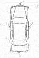
- Figure 1shows a car 10 with a surround view system 11.
- the surround view system 11comprises a front view camera 12, a right side view camera 13, a left side view camera 14 and a rear view camera 15.
- the cameras 11 - 14are connected to a CPU of a controller, which is not shown in Fig. 1 .
- the controlleris connected to further sensors and units, such as a velocity sensor, a steering angle sensor, a GPS unit, and acceleration and orientation sensors.
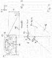
- Figure 2illustrates a car motion of the car 10.
- a wheel base B of the car and a wheel track Lare indicated.
- the car 10is designed according to an Ackermann steering geometry in which an orientation of the steerable front wheels is adjusted such that all four wheels of a vehicle are oriented in tangential direction to a circle of instant rotation.
- An instantaneous centre of curvature "ICC"is in register with the rear axis of the car 10 at a distance R, wherein R is the radius of the car's instant rotation with respect to the yaw movement.
- a two-dimensional vehicle coordinate systemis indicated, which is fixed to a reference point of the car and aligned along a longitudinal and a lateral axis of the car.
- a location of the instantaneous centre of curvature relative to the vehicle coordinate systemis indicated by a vector P ICC .
- an angle ⁇ between an inner rear wheel, the instant centre of curvature and an inner front wheelis equal to a steering angle ⁇ of the inner front wheel.
- inner wheelrefers to the respective wheel that is closer to the centre of curvature.
- a motion of the inner front wheel relative to a ground planeis indicated by a letter v.
- Fig. 3shows a projection of an image point to a ground plane 16.
- An angle of inclination ⁇ relative to the verticalcan be estimated from a location of the image point on the image sensor of the right side view camera 13. If the image point corresponds to a feature of the road the location of the corresponding object point is the projection of the image point onto the ground plane.
- the camera 13has an elevation H above the ground plane. Consequently, the correspond object point is located at a distance H*cos( ⁇ ) from the right side of the car 10.
- X k , X k- 1refer to positions of the car relative to the vehicle coordinate system of Fig. 2 , which is fixed to the car 10, wherein the positions X k , X k- 1 of the car 10 are evaluated at times k* ⁇ t, (k-1)* ⁇ t, respectively, and wherein a position of the vehicle coordinate system is evaluated at time (k-1)* ⁇ t.
- ⁇is a vector of instantaneous rotation
- P ICCis the position of the instantaneous centre of curvature relative to the vehicle coordinate system.
- a vehicle position X_k' relative to a fixed reference frameis derived from the vector X_k and a location R of the vehicle coordinate system relative to the fixed reference frame.
- the movement of the vehicle coordinate systemcan be derived using GPS and/or other sensors, such as a wheel speed sensor, a steering angle sensor, acceleration and orientation sensors.
- the first term on the right hand side of equation (4)is also referred to as "Euler acceleration” and the second term is also referred to as "Coriolis acceleration". Under the assumption that the car stays on track, the centrifugal acceleration is compensated by the car's tyres and does not contribute to the vehicle motion.
- the angular velocity ⁇is time dependent.
- the angular velocity ⁇ at time (k-1)* ⁇ tis used in a computation according to equations (2), (2a) or (3).
- a mean velocity v between times (k-2)* ⁇ t and (k-1)* ⁇ tcan be derived from the comparison of two subsequent projections of camera images.
- the mean velocityis used as the instant velocity at time (k-1)* ⁇ t.
- the angular velocity ⁇is derived from the steering angles of the front wheels and a rotation speed of a front wheel using an Ackermann steering model.
- the Ackermann steering modelgives a good approximation for a car steering with Ackermann geometry, especially for slow velocities when there is little or no slip between the tires and the road.
- the steering angle of the front wheelscan in turn be derived from an angular position of the steering column and the known lateral distance L between the front wheels.
- the ego-motionwhich is derived from the image sequences of the vehicle cameras is used to derive the angular velocity ⁇ .
- the instantaneous positioncan be computed using input from further odometric sensors, such as a GPS system, speed and acceleration sensors of the vehicle or other kinds of odometric sensors.
- GPS position valuescan be used to correct a drift from the true position.
- the egomotionis estimated from an affine projection or transformation to a ground plane, wherein the images of the cameras of the surround view system are merged into the projection to the ground plane.
- Figs. 3 and 4show a projection to a ground plane 16.
- an image pointcorresponds to an object point of an object on the ground plane the image point can be projected to a location of the corresponding object point on the ground plane.
- An angle ⁇ of incidenceis derived from a location of the image point on the camera sensor.
- Fig. 4shows an isometric view of the affine projection of Fig. 3 .
- a distance between the view port plane 17 and a projection center Cis denoted by the letter "f".
- the camera imageis evaluated and the observed scene is reconstructed.
- a sidewalkis detected and its height estimated.
- stationary objectssuch as a lamp post or a tree, are detected and their orientation relative to the ground plane is estimated.
- Objects which are not located at street level and/or which have a proper motioncan distort the optic flow and lead to inaccuracies in the derived egomotion.
- the optical flow vectors resulting from such objectsare filtered out using a RANSAC (random sample consensus) procedure in which outliers are suppressed.
- a road borderis recognized using edge recognition and a digital map, which is stored in a computer memory of the car 10.
- roll and a pitch motions of the carare determined, for example by using acceleration and/or orientation sensors of the car and the ego-motion vectors are corrected by subtracting or by compensating the roll and pitch motions.
- the derived ego-motionis used for a lane-keeping application or for other electronic stabilization applications.
- Fig. 5shows, by way of example, a procedure for obtaining an egomotion.
- camera imagesare acquired from the cameras 11 - 16.
- the camera imagesare combined into a combined image in a step 31.
- an image areais selected for the determination of ego-motion. For example, image areas which correspond to objects outside a street zone, such as buildings and other installations, may be clipped.
- the image pointsare projected to a ground surface, for example by applying an affine transformation or a perspective projection.
- corresponding image pointsare identified in consecutive images.
- optical flow vectorsare derived by comparing the locations of the corresponding image points, for example by computing the difference vector between the position vectors of the corresponding locations.
- a filter procedureis applied, such as a RANSAC procedure or other elimination of outliers and interpolation or by applying a Kalman filter.
- the filteringmay involve storing image values, such as image point brightness values, of a given time window in computer memory and computing an average of the image values.
- an egomotion vector of the caris derived from the optical flow.
Landscapes
- Engineering & Computer Science (AREA)
- Physics & Mathematics (AREA)
- General Physics & Mathematics (AREA)
- Theoretical Computer Science (AREA)
- Computer Vision & Pattern Recognition (AREA)
- Mechanical Engineering (AREA)
- Multimedia (AREA)
- Automation & Control Theory (AREA)
- Transportation (AREA)
- Mathematical Physics (AREA)
- Human Computer Interaction (AREA)
- Image Analysis (AREA)
- Traffic Control Systems (AREA)
- Image Processing (AREA)
- Navigation (AREA)
Description
- The current specification relates to driver assistance systems.
- Advanced driver assistance systems (ADAS) are systems developed to automate and enhance vehicle systems for safety and better driving. Many driver assistance systems use information about a car's position, orientation and motion state to assist the driver in various ways. This information may even be used to drive the vehicle autonomously.
- Among others, visual odometry can be used to determine a car's position. In a system for visual odometry, cameras are used to record input images and image corrections are applied. Features are detected, the features are matched across image frames and an optical flow field is constructed, for example by using a correlation to establish a correspondence between two images, by feature extraction and correlation or by constructing an optical flow field using the Lucas-Kanade method. Odometry errors are detected, the corresponding outliers are removed and the camera motion is estimated from the optical flow, for example using a Kalman filter or by minimizing a cost function that is based on geometric properties of the features.
- The
US 2014/0247352 discloses a multi-camera top view vision system, which generates a stitched virtual top view image. - The following references [1] to [12] relate to the subject matter of the present specification and are hereby incorporated by reference.
- [1]Reza N. Jazar, "Vehicle Dynamics: Theory and Applications", Springer, 19/03/2008.
- [2]Thomas D. Gillespie, "Fundamentals of Vehicle Dynamics". Society of Automotive Engineers, 1992.
- [3] Alonzo Kelly, "Essential Kinematics for Autonomous Vehicles", Robotics Institute, Carnegie Mellon University, 1994.
- [4]Gideon P. Stein, Ofer Mano, Amnon Shashua. "A Robust Method for Computing Vehicle Ego-motion", IEEE Intelligent Vehicles Symposium, 2000.
- [5] Joao P. Barreto, Frederick Martin, Radu Horaud. "Visual Servoing/Tracking Using Central Catadioptric Images", Int. Symposium on Experimental Robotics, Advanced Robotics Series, 2002.
- [6]Alejandro J. Weinstein and Kevin L. Moore, "Pose Estimation of Ackerman Steering Vehicles for Outdoors Autonomous Navigation", Proceedings of 2010 IEEE International Conference on Industrial Automation, Valparaiso, Chile, March 2010.
- [7]Oliver Pink, Frank Moosmann, Alexander Bachmann, "Visual Features for Vehicle Localization and Ego-Motion Estimation", proceeding of: Intelligent Vehicles Symposium, 2009 IEEE.
- [8] D. Cheda, D. Ponsa, A.M. Lopez, "Camera Egomotion Estimation in the ADAS Context", Annual Conference on Intelligent Transportation Systems, 2010.
- [9]Gim Hee Lee, Friedrich Fraundorfer, Marc Pollefeys, "Motion Estimation for Self-Driving Cars with a Generalized Camera", CVPR, 2013.
- [10]Marco Zucchelli, José Santos-Victor, Henrik I. Christensen, "Constrained Structure and Motion Estimation from Optical Flow", ICPR 2002.
- [11]Dan Simon, "Optimal State Estimation: Kalman, H Infinity and Nonlinear Approaches", John Wiley & Sons, 2006.
- [12]P. Wayne Power, Johann. A Schoones, "Understanding Background Mixture Models for Foreground Segmentation", Proceedings Image and Vision Computing New Zealand 2002.
- The references [1], [2], [3] explain models of vehicle kinematics which can be used in an egomotion context.
- Stein et alii [4] propose a single camera application where the egomotion of the vehicle is consistent with the road modelled. Image features in the two images are combined in a global probability function which introduces a global constraint to cope with the aperture problem.
- Barreto et al.[5] describe a visual control of robot motion using central catadioptric systems and present the Jacobian matrix linking the robot's joint velocities to image observations. The solution presented is treated as a least squares problem but they actually defined the state vector that can be used in an Extended Kalman Filter.
- Alejandro et al.[6] study a localization scheme for Ackerman steering vehicles, to be used in outdoors autonomous navigation using a low cost GPS and inclinometer. They use an Extended Kalman Filter to estimate the pose of the vehicle and the sensor biases.
- Pink et al.[7] present a method for vehicle pose estimation and motion tracking using visual features. They assume an initial vehicle pose and then track the pose in geographical coordinates over time, using image data as the only input. They are tracking the vehicle position based on the Ackerman model.
- Cheda et al.[8] study egomotion estimation from a monocular camera under the ADAS context and compare the performance of nonlinear and linear algorithms.
- Lee et al.[9] present a visual ego-motion estimation algorithm for a self-driving car. They model a multicamera system as a generalized camera and applying the nonholonomic motion constraint of a car.
- Marco et al. [10] provide a formulation of a constrained minimization problem for structure and motion estimation from optical flow. He also presents the solution of the optimization problem by Levenberg-Marquardt and direct projection.
- Dan Simon [11] proposes multiple-model estimation methods on page 301, section 10.2, in which the update phase of the Kalman filter is reformulated to weight different models.
- Power and Schoones [12] describe a Gaussian mixture model (GMM) algorithm and an approximation on expectation maximization.
EP2511137 , discloses generation of a surround view of a vehicle using four cameras on its edges. In addition, a birds- eye view is generated. Optical flow is used for determining the distance to other vehicles. - The Use of Optical Flow for Road Navigation, by Giachetti et al, 01.02.98, discloses determination of vehicle egomotion using optical flow. Stabilization of the calculations is achieved using a Kalman- like smoothing filter. According to the present specification, an egomotion of a vehicle is defined as the 3D motion of a camera relative to a fixed coordinate system of the environment, which is also known as a world coordinate system. Furthermore, egomotion also refers to a two-dimensional motion in a given plane of the three-dimensional world coordinate system. This egomotion is also referred to as "2D egomotion". The invention is defined by the appended claims. According to the present specification, the egomotion is calculated from an optical flow. The optical flow is the apparent motion of an image caused by the relative between a camera and the scene, wherein "scene" refers to the objects in the surroundings of the car.
- A method according to the present specification uses an Ackermann model of the steering geometry to describe the vehicle motion and an incremental pose update as a framework to integrate multiple sources of vehicle pose.
- The optical flow is calculated using features that are detected in an image frame of a sequence of images and then matched in a consecutive frame. This information is used to generate the optical flow field for the detected features in those two image frames, or consecutive images. The consecutive images are a projection of the three dimensional scene into a two-dimensional plane, which is also referred to as "viewport plane".
- A model of the road may be used to simplify the estimation of the optical flow. The road forms a simple planar structure and can be represented by only three dominant parameters: the forward translation, the pitch and the yaw. However, according to the present specification, the egomotion can also be estimated with sufficient accuracy without the use of a road model.
- According to a second approach, a Horn-Schunck method is used to estimate the optical flow. A global constraint is introduced to solve the aperture problem and a road model is fitted to the flow fields to remove outliers.
- According to the present specification, a four camera setup of a surround view system is used to generate a surround view, the images of the four cameras are merged into a single projection to a ground plane, which represents the street level and which is also referred to as "top down view".
- A 2D-egomotion is computed from an affine projection of the top down view. Flow field outliers, such as measurement errors or vectors of moving objects are filtered out using a suitable procedure, such as RANSAC.
- The projected view, which is an affine projection of the surround view to the ground plane, is interpreted using a prior calibration, which provides depth and scale information. Alternatively or in addition, a structure is reconstructed from motion algorithms, which gives an explicit reconstruction of the observed scenes and thereby provides an estimate of object distances.
- According to one embodiment, the motion is filtered in order to obtain a consistent position over time. The tracking process estimates the real position of the vehicle with a consistent movement model. According to the present specification, an Ackermann steering model is used as movement model to represent a vehicle with an Ackermann steering geometry.
- According to a further embodiment, The Ackermann model is combined with multiple odometric measurements, such as GPS measurement, vehicle sensors, etc.
- In a first aspect, the present specification discloses a method for determining an ego-motion of a motor vehicle, such as a passenger car, a utility vehicle or a minibus.
- A front view camera records a first sequence of consecutive images of, a left side view camera records a second sequence of consecutive images, a right side view camera records a third sequence of consecutive images, and a rear view camera records a fourth sequence of consecutive images. The first, second, third and fourth image sequences each comprise at least two consecutive images.
- The image sequences are transferred to a computational unit of the motor vehicle. The computational unit merges the first sequence of consecutive images, the second sequence of consecutive images, the third sequence of consecutive images, and the fourth sequence of consecutive images to obtain a sequence of merged images. The merged images correspond to surround view or 360° view of the vehicle's surroundings at a given time.
- Preferably, the respective images and the view fields of adjacent cameras overlap at least partially. By way of example, the images can be merged by matching brightness values, on the basis of the individual pixels, correlating the brightness of the pixels. According to a further embodiment, higher level features such as lines or edges or regions of high contrast or brightness gradient of images from adjacent cameras are matched to each other. In a simple embodiment, the images are merged according to a field of view, position and orientation of the cameras.
- The images of the sequence of merged images, or patches thereof, are projected to a ground plane using an affine projection or transformation, thereby providing a sequence of projected images. Furthermore, a two-dimensional optical flow is determined, based on the sequence of projected images. The optical flow comprises motion vectors of target objects in the surroundings of the vehicle. According to one particular embodiment, an optical flow at a given time is provided by comparing two projected images, which are consecutive in time.
- An egomotion of the vehicle is based on the optical flow. In particular, it is derived by comparing projected images of a first and of a second time and by determining the amount by which a pixel or a group of pixels corresponding to an object in the surroundings has moved. According to the present application, the ego-motion can be derived from the individual camera images of the surround view system or from the merged image of all cameras of the surround view system.
- A kinematic state of the vehicle, such as a position, a speed or a movement is determined based on the ego-motion of the vehicle. The kinematic state is determined, by way of example, with respect to a previous position of the car, to a fixed coordinate system, to an object in the surroundings, or to the instantaneous centre of curvature.
- According to one embodiment, the derivation of the ego-motion comprises deriving an angular velocity of the vehicle around an instantaneous centre of curvature from the optical flow and using the derived angular velocity to derive a velocity of the vehicle, and in particular to derive a velocity of a centre of gravity of the vehicle in a plane that is parallel to a ground plane using an Ackermann steering model.
- According to one particular embodiment, the determination of the ego-motion comprises deriving a current position vector of a target object on a ground plane and a current velocity relative to the target object using a previous position of the target object, a previous velocity relative to the target object and an angular velocity with respect to a rotation around an instantaneous centre of curvature with respect to a yaw motion of the vehicle.
- According to a further embodiment, the Ackermann steering model is used to derive an angular velocity of a yaw motion of the vehicle around an instantaneous centre of curvature from a wheel speed and a steering angle. In particular, the obtained angular speed can be merged with the derived egomotion in an incremental pose update and it can used as a further input to a prediction filter, such as a Kalman filter. Alternatively, other filters, such as a recursive double least squares estimator or a double exponential smoothing filter or other smoothing filters, such as various types of low pass filters for digital signal processing, may be used as well.
- According to embodiments of the present specification, kinematic states of the vehicle, which are obtained from different sources, such as the derived vehicle egomotion, vehicle sensors and a GPS system, are used as an input to the same prediction filter, or they are used as inputs to different prediction filters and the resulting outputs of the different prediction filters are combined to form an estimate of the kinematic state of the vehicle.
- According to a further embodiment, the different sources of vehicle motion can be merged or combined in a probabilistic framework. A likelihood of being correct is determined for each source given a previous measurement. The pose is then updated with the most correct source. In one embodiment, the different sources of vehicle motion are mixed in a Gaussian mixture model.
- According to one embodiment, deriving the egomotion from the optical flow comprises applying a random sample consensus (RANSAC) procedure to motion vectors, which may be motion vectors of the optical flow or ego-motion vectors. The RANSAC procedure may be applied before and/or after applying a prediction filter, such as a Kalman filter. According to the RANSAC procedure, a model is fitted by regression to a subset of the data and the quality of the model is evaluated by measuring the data inliers to the model. The process is repeated until the solution has a pre-determined statistical significance.
- By way of example, a sample subset containing minimal data items is randomly selected from the input dataset in a first step. A fitting model and the corresponding model parameters are computed using only the elements of this sample subset. The size of the sample subset is the smallest sufficient to determine the model parameters. In a second step, the algorithm checks which elements of the entire dataset are consistent with the model instantiated by the estimated model parameters obtained from the first step. A data element will be considered as an outlier if it does not fit the fitting model instantiated by the set of estimated model parameters within some error threshold that defines the maximum deviation attributable to the effect of noise.
- According to one embodiment, the determination of the egomotion comprises deriving motion vectors of individual target objects from the optical flow, deriving a vector of egomotion, also referred to as an average motion vector, from the motion vectors of the optical flow. A prediction filter such as a Kalman filter is applied to the vector of egomotion for predicting a future vector of ego-motion or a future position of the vehicle for tracking the vehicle's position.
- In a particular embodiment, an input to the prediction filter is derived from one or more vectors of ego-motion and motion sensor values, such as wheel speed sensor, acceleration sensor and GPS system output. According to a further embodiment, image regions are detected that correspond to objects that are not located at a ground level and the detected image regions are disregarded or masked out.
- According to a further aspect, the present specification discloses a computer program product, such as an executable file in a persistent memory, such as a memory stick, a hard-disk or a DVD, or in volatile memory, such as a computer RAM. The executable file or executable code causes a processing unit to execute one of the preceding methods when it is loaded into a program memory of a processor.
- According to a further aspect, the present specification discloses an Ego-motion detection system for a motor vehicle. The Ego-motion detection system comprises a computation unit, the computation that has a first input connection for receiving data from a front view camera, a second input connection for receiving data from a right side view camera, a third input connection for receiving data from left side view camera and, a fourth input connection for receiving data from a rear view camera.
- The four input connections may also be realized by a single input connection, for example, if image data from the respective cameras is transmitted in alternating time slices or alternating data chunks. In particular, the camera data may be transmitted via cables of a data bus.
- The computation unit comprises a processing unit, such as a microprocessor with a computer memory, which is operative to obtain a first sequence of consecutive images from the front view camera, a second sequence of consecutive images from the left side view camera, a third sequence of consecutive images from the right side view camera, and a fourth sequence of consecutive images from the rear view camera via respective the input connections.
- Furthermore, the camera or the cameras may comprise a camera processing unit for basic image processing. The camera processing unit is different from the main processing unit that does the egomotion calculation.
- Furthermore, the processing unit is operative to merge the first sequence of consecutive images, the second sequence of consecutive images, the third sequence of consecutive images, and the fourth sequence of consecutive images to obtain a sequence of merged images, and to provide a virtual projection of the images of the sequence of merged images or patches thereof to a ground plane using an affine projection or transformation thereby obtaining a sequence of projected images.
- Herein, a virtual projection refers to the operation of mapping the content of a first memory area to the content of a second memory area according to a transformation algorithm of the projection.
- Moreover, the processing unit is operative to determine an optical flow, based on the sequence of projected images, to determine an ego-motion of the vehicle based on the optical flow and to predict a kinematic state of the car based on the ego-motion. The optical flow comprises motion vectors of target objects in the surroundings of the vehicle.
- Furthermore, the current specification discloses the aforementioned ego-motion detection system with a front view camera that is connected to the first input, a right side view camera that is connected to the second input, a left side view camera that is connected to the third input, a rear view camera that is connected to the fourth input.
- Moreover, the current specification discloses a car or a motor vehicle with the aforementioned ego-motion detection system, wherein the front view camera is provided at a front side of the car, the right side view camera is provided at a right side of the car, the left side view camera is provided at a left side of the car, and the rear view camera is provided at a rear side of the car.
- The subject matter of the present specification is further explained with respect to the following Figures in which
- Fig. 1
- shows a car with a surround view system,
- Fig. 2
- illustrates a car motion of the car of
Fig. 1 around an instantaneous centre of rotation, and - Fig. 3
- illustrates a projection to a ground plane of an image point recorded with the surround view system of
Fig. 1 , - Fig. 4
- illustrates in further detail the ground plane projection of
Fig. 3 , and - Fig. 5
- shows a procedure for deriving an egomotion of the car.
- In the following description, details are provided to describe the embodiments of the present specification. It shall be apparent to one skilled in the art, however, that the embodiments may be practised without such details.
Figure 1 shows acar 10 with asurround view system 11. Thesurround view system 11 comprises afront view camera 12, a rightside view camera 13, a leftside view camera 14 and arear view camera 15. The cameras 11 - 14 are connected to a CPU of a controller, which is not shown inFig. 1 . The controller is connected to further sensors and units, such as a velocity sensor, a steering angle sensor, a GPS unit, and acceleration and orientation sensors.Figure 2 illustrates a car motion of thecar 10. A wheel base B of the car and a wheel track L are indicated. Thecar 10 is designed according to an Ackermann steering geometry in which an orientation of the steerable front wheels is adjusted such that all four wheels of a vehicle are oriented in tangential direction to a circle of instant rotation. An instantaneous centre of curvature "ICC" is in register with the rear axis of thecar 10 at a distance R, wherein R is the radius of the car's instant rotation with respect to the yaw movement.- A two-dimensional vehicle coordinate system is indicated, which is fixed to a reference point of the car and aligned along a longitudinal and a lateral axis of the car. A location of the instantaneous centre of curvature relative to the vehicle coordinate system is indicated by a vector
P ICC. - In an Ackermann steering geometry according to
Fig. 2 , an angle α between an inner rear wheel, the instant centre of curvature and an inner front wheel is equal to a steering angle α of the inner front wheel. Herein, "inner wheel" refers to the respective wheel that is closer to the centre of curvature. A motion of the inner front wheel relative to a ground plane is indicated by a letter v. Fig. 3 shows a projection of an image point to aground plane 16. An angle of inclination θ relative to the vertical can be estimated from a location of the image point on the image sensor of the rightside view camera 13. If the image point corresponds to a feature of the road the location of the corresponding object point is the projection of the image point onto the ground plane. In the example ofFig. 3 , thecamera 13 has an elevation H above the ground plane. Consequently, the correspond object point is located at a distance H*cos(θ) from the right side of thecar 10.- According to one embodiment, the vehicle is tracked using a constant acceleration model and a one-step procedure, wherein the values of a car position x_k and a car velocity v= d/dt(x_k) at time k*Δt are predicted using the respective values of the position and velocity at the earlier time (k-1)* Δt according to the equations


Fig. 2 , which is fixed to thecar 10, wherein the positionsXk, Xk-1 of thecar 10 are evaluated at times k* Δt, (k-1)* Δt, respectively, and wherein a position of the vehicle coordinate system is evaluated at time (k-1)* Δt. - The car velocity at the reference point can be derived from the location of the reference point relative to the instantaneous centre of curvature and the current angular velocity according to

ω is a vector of instantaneous rotation andP ICC is the position of the instantaneous centre of curvature relative to the vehicle coordinate system. The relationship according to equation (3) is used in equations (2), (2a). In equations (1) - (2a) the vector arrows have been omitted for easier reading. - A vehicle position X_k' relative to a fixed reference frame, also known as "world coordinate system", is derived from the vector X_k and a location R of the vehicle coordinate system relative to the fixed reference frame. By way of example the movement of the vehicle coordinate system can be derived using GPS and/or other sensors, such as a wheel speed sensor, a steering angle sensor, acceleration and orientation sensors.
- According to a further embodiment, the accuracy is improved by incorporating a time dependent acceleration according to

- In general, the angular velocityω is time dependent. According to one embodiment, the angular velocityω at time (k-1)* Δt is used in a computation according to equations (2), (2a) or (3).
- According to the present specification, a mean velocity v between times (k-2)* Δt and (k-1)* Δt can be derived from the comparison of two subsequent projections of camera images. In a first approximation, the mean velocity is used as the instant velocity at time (k-1)* Δt.
- According to one embodiment, the angular velocity ω is derived from the steering angles of the front wheels and a rotation speed of a front wheel using an Ackermann steering model. The Ackermann steering model gives a good approximation for a car steering with Ackermann geometry, especially for slow velocities when there is little or no slip between the tires and the road.
- The steering angle of the front wheels can in turn be derived from an angular position of the steering column and the known lateral distance L between the front wheels. According to a further embodiment, the ego-motion, which is derived from the image sequences of the vehicle cameras is used to derive the angular velocity ω.
- With reference to
Fig. 2 , a radius of curvature R_2 with respect to the instantaneous curvature centre and an inner front wheel can be derived as R_2 = B/sin(α), wherein α is a steering angle of the inner front wheel and B is the wheel base of the car. If the inner front wheel moves with a velocity v, which can be derived from a rotation speed of the inner front wheel and the wheel's diameter, the angular velocity of the instantaneous rotation of the car in a horizontal plane, also known as "yaw", is ω = v/R_2 = v*sin(α)/B. - For better accuracy, the instantaneous position can be computed using input from further odometric sensors, such as a GPS system, speed and acceleration sensors of the vehicle or other kinds of odometric sensors. In particular, GPS position values can be used to correct a drift from the true position.
- According to one embodiment, the egomotion is estimated from an affine projection or transformation to a ground plane, wherein the images of the cameras of the surround view system are merged into the projection to the ground plane.
Figs. 3 and 4 show a projection to aground plane 16.- Under the assumption that an image point corresponds to an object point of an object on the ground plane the image point can be projected to a location of the corresponding object point on the ground plane. An angle θ of incidence is derived from a location of the image point on the camera sensor. A location Y of the projection is then derived using the height H of the camera sensor above street level as Y = H * cos(θ).
Fig. 4 shows an isometric view of the affine projection ofFig. 3 . InFig. 4 , a point in aview port plane 17 is denoted by p = (u, v) and a corresponding point in theground plane 16 is denoted by P = (X, Y). A distance between theview port plane 17 and a projection center C is denoted by the letter "f".- According to further embodiments, the camera image is evaluated and the observed scene is reconstructed. In one embodiment, a sidewalk is detected and its height estimated. According to another embodiment stationary objects, such as a lamp post or a tree, are detected and their orientation relative to the ground plane is estimated.
- Objects which are not located at street level and/or which have a proper motion can distort the optic flow and lead to inaccuracies in the derived egomotion. According to one embodiment, the optical flow vectors resulting from such objects are filtered out using a RANSAC (random sample consensus) procedure in which outliers are suppressed. According to further embodiments, a road border is recognized using edge recognition and a digital map, which is stored in a computer memory of the
car 10. - According to a further embodiment, roll and a pitch motions of the car are determined, for example by using acceleration and/or orientation sensors of the car and the ego-motion vectors are corrected by subtracting or by compensating the roll and pitch motions.
- According to further modifications, the derived ego-motion is used for a lane-keeping application or for other electronic stabilization applications.
Fig. 5 shows, by way of example, a procedure for obtaining an egomotion. In astep 30, camera images are acquired from the cameras 11 - 16. The camera images are combined into a combined image in astep 31. In astep 32, an image area is selected for the determination of ego-motion. For example, image areas which correspond to objects outside a street zone, such as buildings and other installations, may be clipped. In astep 33 the image points are projected to a ground surface, for example by applying an affine transformation or a perspective projection.- In a
step 34, corresponding image points are identified in consecutive images. In astep 35, optical flow vectors are derived by comparing the locations of the corresponding image points, for example by computing the difference vector between the position vectors of the corresponding locations. In astep 36, a filter procedure is applied, such as a RANSAC procedure or other elimination of outliers and interpolation or by applying a Kalman filter. In particular, the filtering may involve storing image values, such as image point brightness values, of a given time window in computer memory and computing an average of the image values. In astep 37, an egomotion vector of the car is derived from the optical flow. - The particular sequence of the steps
Fig. 5 is only provided by way of example. For example, the images of the cameras may also be combined after carrying out the projection to ground level. - Although the above description contains much specificity, these should not be construed as limiting the scope of the embodiments but merely providing illustration of the foreseeable embodiments. Especially the above stated advantages of the embodiments should not be construed as limiting the scope of the embodiments but merely to explain possible achievements if the described embodiments are put into practise. Thus, the scope of the embodiments should be determined by the claims and their equivalents, rather than by the examples given.
- 10
- car
- 11
- surround view system
- 12
- front view camera
- 13
- right side view camera
- 14
- left side view camera
- 15
- rear view camera
- 16
- ground plane
- 30 - 37
- method steps


Claims (11)
- Method for determining an ego-motion of a vehicle comprising- recording a first sequence of consecutive images of a front view camera, a second sequence of consecutive images of a left side view camera, a third sequence of consecutive images of a right side view camera, and a fourth sequence of consecutive images of a rear view camera,- merging the first sequence of consecutive images, the second sequence of consecutive images, the third sequence of consecutive images, and the fourth sequence of consecutive images by providing a virtual projection of the images to a ground plane using an affine projection, thereby obtaining a sequence of projected images to obtain a sequence of merged images,- determining an optical flow, based on the sequence of projected images, the optical flow comprising motion vectors of target objects in the surroundings of the vehicle,characterized in that the method further comprises:- determining an ego-motion of the vehicle based on the optical flow, deriving an angular velocity of the vehicle around an instantaneous center of curvature from a wheel speed and a steering angle using an Ackermann steering model, merging the determined ego-motion based on the optical flow and the angular velocity of the vehicle in an incremental pose update, and predicting a kinematic state of the car based on the incremental pose update.
- Method according to claim 1, wherein the determination of the ego-motion based on the optical flow comprises- deriving an angular velocity of the vehicle around an instantaneous center of curvature from the optical flow,- using the derived angular velocity to derive a velocity of the vehicle.
- Method according claim 1 or claim 2, wherein the prediction of the kinematic state further comprises deriving a current position vector of a target object and a current velocity relative to the target object from a previous position of the target object, a previous velocity relative to the target object and an angular velocity with respect to a rotation around an instantaneous center of curvature.
- Method according to one of the claims 1 to 3, wherein the determination of the ego-motion based on the optical flow comprises deriving motion vectors from the optical flow, applying a RANSAC procedure to the motion vectors.
- Method according to one of the claims 1 to 4, wherein the determination of the based on the optical flow comprises deriving motion vectors from the optical flow, deriving vector of ego-motion from the motion vectors of the optical flow, applying a prediction filter to the vector of ego-motion for predicting a future vector of ego- motion.
- Method according to claim 5 wherein an input to the prediction filter is derived from one or more vectors of ego-motion and from one or more motion sensor values.
- Method according to one of the preceding claims, comprising detecting image regions that correspond to objects that are not at a ground level and masking out/disregarding the detected image regions.
- Computer program product for executing a method according to one of the claims 1 to 7.
- Ego-Motion detection system for a motor vehicle comprising a computation unit, the computation unit comprising a first input connection for receiving data from a front view camera, a second input connection for receiving data from a right side view camera, a third input connection for receiving data from left side view camera, a fourth input connection for receiving data from a rear view camera, the computation unit comprising a processing unit for- obtaining a first sequence of consecutive images from the front view camera, a second sequence of consecutive images from the left side view camera, a third sequence of consecutive images from the right side view camera, and a fourth sequence of consecutive images from the rear view camera,- merging the first sequence of consecutive images, the second sequence of consecutive images, the third sequence of consecutive images, and the fourth sequence of consecutive images by providing a virtual projection of the images to a ground plane using an affine projection, thereby obtaining a sequence of projected images to obtain a sequence of merged images,- determining an optical flow, based on the sequence of projected images, the optical flow comprising motion vectors of target objects in the surroundings of the vehicle,- determining an ego-motion of the vehicle based on the optical flow, deriving an angular velocity of the vehicle around an instantaneous center of curvature from a wheel speed and a steering angle using an Ackermann steering model, merging the determined ego-motion based on the optical flow and the angular velocity of the vehicle in an incremental pose update, and predicting a kinematic state of the car based on the incremental pose update.
- Ego-Motion detection system according to claim 9, comprising a front view camera that is connected to the first input, a right side view camera that is connected to the second input, a left side view camera that is connected to the third input, a rear view camera that is connected to the fourth input.
- Car with an ego-motion detection system according to claim 10, the front view camera being provided at a front side of the car, the right side view camera being provided at a right side of the car, the left side view camera being provided at a left side of the car, and the rear view camera being provided at a rear side of the car.
Priority Applications (7)
| Application Number | Priority Date | Filing Date | Title |
|---|---|---|---|
| EP15155191.8AEP3057061B1 (en) | 2015-02-16 | 2015-02-16 | Method and device for the estimation of car egomotion from surround view images |
| PCT/EP2016/050937WO2016131585A1 (en) | 2015-02-16 | 2016-01-19 | Method and device for the estimation of car egomotion from surround view images |
| DE112016000187.8TDE112016000187T5 (en) | 2015-02-16 | 2016-01-19 | Method and apparatus for estimating vehicle intrinsic movement based on panoramic images |
| JP2017530610AJP6620153B2 (en) | 2015-02-16 | 2016-01-19 | Method and apparatus for estimating car egomotion from surround view images |
| KR1020177018249AKR102508843B1 (en) | 2015-02-16 | 2016-01-19 | Method and device for the estimation of car egomotion from surround view images |
| CN201680005504.XACN107111879B (en) | 2015-02-16 | 2016-01-19 | Method and apparatus for estimating vehicle's own motion by panoramic looking-around image |
| US15/678,774US10867401B2 (en) | 2015-02-16 | 2017-08-16 | Method and device for the estimation of car ego-motion from surround view images |
Applications Claiming Priority (1)
| Application Number | Priority Date | Filing Date | Title |
|---|---|---|---|
| EP15155191.8AEP3057061B1 (en) | 2015-02-16 | 2015-02-16 | Method and device for the estimation of car egomotion from surround view images |
Publications (2)
| Publication Number | Publication Date |
|---|---|
| EP3057061A1 EP3057061A1 (en) | 2016-08-17 |
| EP3057061B1true EP3057061B1 (en) | 2017-08-30 |
Family
ID=52472232
Family Applications (1)
| Application Number | Title | Priority Date | Filing Date |
|---|---|---|---|
| EP15155191.8AActiveEP3057061B1 (en) | 2015-02-16 | 2015-02-16 | Method and device for the estimation of car egomotion from surround view images |
Country Status (7)
| Country | Link |
|---|---|
| US (1) | US10867401B2 (en) |
| EP (1) | EP3057061B1 (en) |
| JP (1) | JP6620153B2 (en) |
| KR (1) | KR102508843B1 (en) |
| CN (1) | CN107111879B (en) |
| DE (1) | DE112016000187T5 (en) |
| WO (1) | WO2016131585A1 (en) |
Cited By (10)
| Publication number | Priority date | Publication date | Assignee | Title |
|---|---|---|---|---|
| US10417816B2 (en) | 2017-06-16 | 2019-09-17 | Nauto, Inc. | System and method for digital environment reconstruction |
| US10430695B2 (en) | 2017-06-16 | 2019-10-01 | Nauto, Inc. | System and method for contextualized vehicle operation determination |
| US10453150B2 (en) | 2017-06-16 | 2019-10-22 | Nauto, Inc. | System and method for adverse vehicle event determination |
| US10503990B2 (en) | 2016-07-05 | 2019-12-10 | Nauto, Inc. | System and method for determining probability that a vehicle driver is associated with a driver identifier |
| US10703268B2 (en) | 2016-11-07 | 2020-07-07 | Nauto, Inc. | System and method for driver distraction determination |
| US10733460B2 (en) | 2016-09-14 | 2020-08-04 | Nauto, Inc. | Systems and methods for safe route determination |
| US10769456B2 (en) | 2016-09-14 | 2020-09-08 | Nauto, Inc. | Systems and methods for near-crash determination |
| US11175145B2 (en) | 2016-08-09 | 2021-11-16 | Nauto, Inc. | System and method for precision localization and mapping |
| US11392131B2 (en) | 2018-02-27 | 2022-07-19 | Nauto, Inc. | Method for determining driving policy |
| KR20230055228A (en) | 2021-10-18 | 2023-04-25 | 서울대학교산학협력단 | Radar-Based Ego-Motion Estimation of Autonomous Robot for Simultaneous Localization and Mapping |
Families Citing this family (17)
| Publication number | Priority date | Publication date | Assignee | Title |
|---|---|---|---|---|
| DE102017200278A1 (en)* | 2017-01-10 | 2018-07-12 | Volkswagen Aktiengesellschaft | Method for determining a direction of movement of a camera |
| US10762399B2 (en)* | 2017-12-18 | 2020-09-01 | Ford Global Technologies, Llc | Using deep video frame prediction for training a controller of an autonomous vehicle |
| DE102017223325A1 (en)* | 2017-12-20 | 2019-06-27 | Conti Temic Microelectronic Gmbh | Method and device for merging measurements from different sources of information |
| US10545506B2 (en) | 2018-02-14 | 2020-01-28 | Ford Global Technologies, Llc | Methods and apparatus to perform visual odometry using a vehicle camera system |
| CN109189060B (en)* | 2018-07-25 | 2021-01-12 | 博众精工科技股份有限公司 | Point stabilization control method and device for mobile robot |
| CN109300143B (en) | 2018-09-07 | 2021-07-27 | 百度在线网络技术(北京)有限公司 | Method, device and equipment for determining motion vector field, storage medium and vehicle |
| CN112930557B (en)* | 2018-09-26 | 2025-09-02 | 相干逻辑公司 | Any world view generation |
| KR102559203B1 (en)* | 2018-10-01 | 2023-07-25 | 삼성전자주식회사 | Method and apparatus of outputting pose information |
| KR102270799B1 (en)* | 2018-12-07 | 2021-06-29 | 아진산업(주) | Around View Monitor System with camera blind spot restoration |
| JP7374602B2 (en)* | 2019-03-29 | 2023-11-07 | 日立建機株式会社 | work vehicle |
| US10949685B2 (en)* | 2019-07-22 | 2021-03-16 | Caterpillar Inc. | Excluding a component of a work machine from a video frame based on motion information |
| CN112572462B (en)* | 2019-09-30 | 2022-09-20 | 阿波罗智能技术(北京)有限公司 | Automatic driving control method and device, electronic equipment and storage medium |
| CN111862210B (en)* | 2020-06-29 | 2023-05-12 | 辽宁石油化工大学 | Object detection and positioning method and device based on looking-around camera |
| DE102020120713A1 (en) | 2020-08-05 | 2022-02-10 | Ford Global Technologies Llc | Method for operating a high-beam assistance system of a motor vehicle and motor vehicle |
| DE102020213855A1 (en) | 2020-11-04 | 2022-05-05 | Robert Bosch Gesellschaft mit beschränkter Haftung | Method, computer program, storage medium and control unit for object recognition |
| CN115195625A (en)* | 2021-04-12 | 2022-10-18 | 华为技术有限公司 | Vehicle-mounted sensing device and vehicle |
| DE102022206377A1 (en)* | 2022-06-24 | 2024-01-04 | Robert Bosch Gesellschaft mit beschränkter Haftung | Method for providing image recordings |
Family Cites Families (18)
| Publication number | Priority date | Publication date | Assignee | Title |
|---|---|---|---|---|
| US6535114B1 (en)* | 2000-03-22 | 2003-03-18 | Toyota Jidosha Kabushiki Kaisha | Method and apparatus for environment recognition |
| JP3776094B2 (en)* | 2002-05-09 | 2006-05-17 | 松下電器産業株式会社 | Monitoring device, monitoring method and monitoring program |
| JP2004361839A (en) | 2003-06-06 | 2004-12-24 | Oki Data Corp | Fixing device |
| KR100630088B1 (en)* | 2004-12-28 | 2006-09-27 | 삼성전자주식회사 | Vehicle monitoring apparatus and method using optical flow |
| JP4919036B2 (en)* | 2007-01-30 | 2012-04-18 | アイシン精機株式会社 | Moving object recognition device |
| US20080319664A1 (en)* | 2007-06-25 | 2008-12-25 | Tidex Systems Ltd. | Navigation aid |
| JP5068779B2 (en)* | 2009-02-27 | 2012-11-07 | 現代自動車株式会社 | Vehicle surroundings overhead image display apparatus and method |
| JP5388059B2 (en)* | 2009-07-02 | 2014-01-15 | 国立大学法人九州工業大学 | Object detection method and object detection apparatus based on background image estimation |
| JP5251814B2 (en)* | 2009-09-28 | 2013-07-31 | 三菱自動車工業株式会社 | Driving assistance device |
| US20110169957A1 (en)* | 2010-01-14 | 2011-07-14 | Ford Global Technologies, Llc | Vehicle Image Processing Method |
| JP2011199735A (en)* | 2010-03-23 | 2011-10-06 | Toshiba Corp | Image processing device, and image processing system |
| EP2511137B1 (en)* | 2011-04-14 | 2019-03-27 | Harman Becker Automotive Systems GmbH | Vehicle Surround View System |
| CN102654917B (en)* | 2011-04-27 | 2014-11-26 | 清华大学 | Method and system for sensing motion gestures of moving body |
| CN102999759B (en)* | 2012-11-07 | 2015-10-07 | 东南大学 | A kind of state of motion of vehicle method of estimation based on light stream |
| US10179543B2 (en) | 2013-02-27 | 2019-01-15 | Magna Electronics Inc. | Multi-camera dynamic top view vision system |
| JP6156486B2 (en)* | 2013-03-28 | 2017-07-05 | アイシン精機株式会社 | Perimeter monitoring apparatus and program |
| CN104104915A (en)* | 2014-07-21 | 2014-10-15 | 四川沛阳科技有限公司 | Multifunctional driving monitoring early warning system based on mobile terminal |
| CN104318561B (en)* | 2014-10-22 | 2017-05-03 | 上海理工大学 | Method for detecting vehicle motion information based on integration of binocular stereoscopic vision and optical flow |
- 2015
- 2015-02-16EPEP15155191.8Apatent/EP3057061B1/enactiveActive
- 2016
- 2016-01-19CNCN201680005504.XApatent/CN107111879B/enactiveActive
- 2016-01-19KRKR1020177018249Apatent/KR102508843B1/enactiveActive
- 2016-01-19JPJP2017530610Apatent/JP6620153B2/enactiveActive
- 2016-01-19DEDE112016000187.8Tpatent/DE112016000187T5/enactivePending
- 2016-01-19WOPCT/EP2016/050937patent/WO2016131585A1/ennot_activeCeased
- 2017
- 2017-08-16USUS15/678,774patent/US10867401B2/enactiveActive
Non-Patent Citations (1)
| Title |
|---|
| None* |
Cited By (14)
| Publication number | Priority date | Publication date | Assignee | Title |
|---|---|---|---|---|
| US10503990B2 (en) | 2016-07-05 | 2019-12-10 | Nauto, Inc. | System and method for determining probability that a vehicle driver is associated with a driver identifier |
| US11580756B2 (en) | 2016-07-05 | 2023-02-14 | Nauto, Inc. | System and method for determining probability that a vehicle driver is associated with a driver identifier |
| US11175145B2 (en) | 2016-08-09 | 2021-11-16 | Nauto, Inc. | System and method for precision localization and mapping |
| US10733460B2 (en) | 2016-09-14 | 2020-08-04 | Nauto, Inc. | Systems and methods for safe route determination |
| US10769456B2 (en) | 2016-09-14 | 2020-09-08 | Nauto, Inc. | Systems and methods for near-crash determination |
| US10703268B2 (en) | 2016-11-07 | 2020-07-07 | Nauto, Inc. | System and method for driver distraction determination |
| US10453150B2 (en) | 2017-06-16 | 2019-10-22 | Nauto, Inc. | System and method for adverse vehicle event determination |
| US11017479B2 (en) | 2017-06-16 | 2021-05-25 | Nauto, Inc. | System and method for adverse vehicle event determination |
| US11164259B2 (en) | 2017-06-16 | 2021-11-02 | Nauto, Inc. | System and method for adverse vehicle event determination |
| US10417816B2 (en) | 2017-06-16 | 2019-09-17 | Nauto, Inc. | System and method for digital environment reconstruction |
| US11281944B2 (en) | 2017-06-16 | 2022-03-22 | Nauto, Inc. | System and method for contextualized vehicle operation determination |
| US10430695B2 (en) | 2017-06-16 | 2019-10-01 | Nauto, Inc. | System and method for contextualized vehicle operation determination |
| US11392131B2 (en) | 2018-02-27 | 2022-07-19 | Nauto, Inc. | Method for determining driving policy |
| KR20230055228A (en) | 2021-10-18 | 2023-04-25 | 서울대학교산학협력단 | Radar-Based Ego-Motion Estimation of Autonomous Robot for Simultaneous Localization and Mapping |
Also Published As
| Publication number | Publication date |
|---|---|
| CN107111879B (en) | 2021-01-22 |
| EP3057061A1 (en) | 2016-08-17 |
| JP6620153B2 (en) | 2019-12-11 |
| JP2018506768A (en) | 2018-03-08 |
| KR20170118040A (en) | 2017-10-24 |
| US20170345164A1 (en) | 2017-11-30 |
| WO2016131585A1 (en) | 2016-08-25 |
| CN107111879A (en) | 2017-08-29 |
| US10867401B2 (en) | 2020-12-15 |
| DE112016000187T5 (en) | 2017-08-31 |
| KR102508843B1 (en) | 2023-03-09 |
Similar Documents
| Publication | Publication Date | Title |
|---|---|---|
| EP3057061B1 (en) | Method and device for the estimation of car egomotion from surround view images | |
| JP2018506768A5 (en) | ||
| Qin et al. | Avp-slam: Semantic visual mapping and localization for autonomous vehicles in the parking lot | |
| CN111060094B (en) | Vehicle positioning method and device | |
| Häne et al. | 3D visual perception for self-driving cars using a multi-camera system: Calibration, mapping, localization, and obstacle detection | |
| McGuire et al. | Efficient optical flow and stereo vision for velocity estimation and obstacle avoidance on an autonomous pocket drone | |
| Poddar et al. | Evolution of visual odometry techniques | |
| Kellner et al. | Instantaneous ego-motion estimation using multiple Doppler radars | |
| EP3009789A1 (en) | Monocular-motion-stereo distance estimation method, and monocular-motion-stereo distance estimation apparatus | |
| WO2016170330A1 (en) | Processing a series of images to identify at least a portion of an object | |
| Han et al. | Robust ego-motion estimation and map matching technique for autonomous vehicle localization with high definition digital map | |
| Musleh et al. | Visual ego motion estimation in urban environments based on uv disparity | |
| US11514588B1 (en) | Object localization for mapping applications using geometric computer vision techniques | |
| Hong et al. | Visual inertial odometry using coupled nonlinear optimization | |
| Serov et al. | Visual-multi-sensor odometry with application in autonomous driving | |
| Roggeman et al. | Embedded vision-based localization and model predictive control for autonomous exploration | |
| Song et al. | BIG-STEP: Better-initialized state estimator for legged robots with fast and robust ground segmentation | |
| JP7594691B2 (en) | Drive system, vehicle and method for automated and/or assisted driving | |
| CN116757918A (en) | Binocular stereoscopic vision-based vehicle scratch identification method and device | |
| Hoang et al. | Planar motion estimation using omnidirectional camera and laser rangefinder | |
| Musleh et al. | Continuous pose estimation for stereo vision based on UV disparity applied to visual odometry in urban environments | |
| Weydert | Model-based ego-motion and vehicle parameter estimation using visual odometry | |
| Gomes et al. | Visual Odometry through Optical Flow Integrated with a Multi-sensor Localization System Applied to Mining Vehicles | |
| US20240144487A1 (en) | Method for tracking position of object and system for tracking position of object | |
| Winkens et al. | Optical truck tracking for autonomous platooning |
Legal Events
| Date | Code | Title | Description |
|---|---|---|---|
| PUAI | Public reference made under article 153(3) epc to a published international application that has entered the european phase | Free format text:ORIGINAL CODE: 0009012 | |
| AK | Designated contracting states | Kind code of ref document:A1 Designated state(s):AL AT BE BG CH CY CZ DE DK EE ES FI FR GB GR HR HU IE IS IT LI LT LU LV MC MK MT NL NO PL PT RO RS SE SI SK SM TR | |
| AX | Request for extension of the european patent | Extension state:BA ME | |
| 17P | Request for examination filed | Effective date:20170217 | |
| RBV | Designated contracting states (corrected) | Designated state(s):AL AT BE BG CH CY CZ DE DK EE ES FI FR GB GR HR HU IE IS IT LI LT LU LV MC MK MT NL NO PL PT RO RS SE SI SK SM TR | |
| GRAP | Despatch of communication of intention to grant a patent | Free format text:ORIGINAL CODE: EPIDOSNIGR1 | |
| INTG | Intention to grant announced | Effective date:20170405 | |
| GRAS | Grant fee paid | Free format text:ORIGINAL CODE: EPIDOSNIGR3 | |
| GRAA | (expected) grant | Free format text:ORIGINAL CODE: 0009210 | |
| AK | Designated contracting states | Kind code of ref document:B1 Designated state(s):AL AT BE BG CH CY CZ DE DK EE ES FI FR GB GR HR HU IE IS IT LI LT LU LV MC MK MT NL NO PL PT RO RS SE SI SK SM TR | |
| REG | Reference to a national code | Ref country code:GB Ref legal event code:FG4D | |
| REG | Reference to a national code | Ref country code:CH Ref legal event code:EP | |
| REG | Reference to a national code | Ref country code:AT Ref legal event code:REF Ref document number:924254 Country of ref document:AT Kind code of ref document:T Effective date:20170915 | |
| REG | Reference to a national code | Ref country code:IE Ref legal event code:FG4D | |
| REG | Reference to a national code | Ref country code:DE Ref legal event code:R096 Ref document number:602015004350 Country of ref document:DE | |
| REG | Reference to a national code | Ref country code:NL Ref legal event code:MP Effective date:20170830 | |
| REG | Reference to a national code | Ref country code:LT Ref legal event code:MG4D | |
| REG | Reference to a national code | Ref country code:AT Ref legal event code:MK05 Ref document number:924254 Country of ref document:AT Kind code of ref document:T Effective date:20170830 | |
| PG25 | Lapsed in a contracting state [announced via postgrant information from national office to epo] | Ref country code:NO Free format text:LAPSE BECAUSE OF FAILURE TO SUBMIT A TRANSLATION OF THE DESCRIPTION OR TO PAY THE FEE WITHIN THE PRESCRIBED TIME-LIMIT Effective date:20171130 Ref country code:FI Free format text:LAPSE BECAUSE OF FAILURE TO SUBMIT A TRANSLATION OF THE DESCRIPTION OR TO PAY THE FEE WITHIN THE PRESCRIBED TIME-LIMIT Effective date:20170830 Ref country code:AT Free format text:LAPSE BECAUSE OF FAILURE TO SUBMIT A TRANSLATION OF THE DESCRIPTION OR TO PAY THE FEE WITHIN THE PRESCRIBED TIME-LIMIT Effective date:20170830 Ref country code:LT Free format text:LAPSE BECAUSE OF FAILURE TO SUBMIT A TRANSLATION OF THE DESCRIPTION OR TO PAY THE FEE WITHIN THE PRESCRIBED TIME-LIMIT Effective date:20170830 Ref country code:HR Free format text:LAPSE BECAUSE OF FAILURE TO SUBMIT A TRANSLATION OF THE DESCRIPTION OR TO PAY THE FEE WITHIN THE PRESCRIBED TIME-LIMIT Effective date:20170830 Ref country code:SE Free format text:LAPSE BECAUSE OF FAILURE TO SUBMIT A TRANSLATION OF THE DESCRIPTION OR TO PAY THE FEE WITHIN THE PRESCRIBED TIME-LIMIT Effective date:20170830 | |
| REG | Reference to a national code | Ref country code:FR Ref legal event code:PLFP Year of fee payment:4 | |
| PG25 | Lapsed in a contracting state [announced via postgrant information from national office to epo] | Ref country code:RS Free format text:LAPSE BECAUSE OF FAILURE TO SUBMIT A TRANSLATION OF THE DESCRIPTION OR TO PAY THE FEE WITHIN THE PRESCRIBED TIME-LIMIT Effective date:20170830 Ref country code:IS Free format text:LAPSE BECAUSE OF FAILURE TO SUBMIT A TRANSLATION OF THE DESCRIPTION OR TO PAY THE FEE WITHIN THE PRESCRIBED TIME-LIMIT Effective date:20171230 Ref country code:LV Free format text:LAPSE BECAUSE OF FAILURE TO SUBMIT A TRANSLATION OF THE DESCRIPTION OR TO PAY THE FEE WITHIN THE PRESCRIBED TIME-LIMIT Effective date:20170830 Ref country code:BG Free format text:LAPSE BECAUSE OF FAILURE TO SUBMIT A TRANSLATION OF THE DESCRIPTION OR TO PAY THE FEE WITHIN THE PRESCRIBED TIME-LIMIT Effective date:20171130 Ref country code:ES Free format text:LAPSE BECAUSE OF FAILURE TO SUBMIT A TRANSLATION OF THE DESCRIPTION OR TO PAY THE FEE WITHIN THE PRESCRIBED TIME-LIMIT Effective date:20170830 | |
| PG25 | Lapsed in a contracting state [announced via postgrant information from national office to epo] | Ref country code:NL Free format text:LAPSE BECAUSE OF FAILURE TO SUBMIT A TRANSLATION OF THE DESCRIPTION OR TO PAY THE FEE WITHIN THE PRESCRIBED TIME-LIMIT Effective date:20170830 | |
| PG25 | Lapsed in a contracting state [announced via postgrant information from national office to epo] | Ref country code:DK Free format text:LAPSE BECAUSE OF FAILURE TO SUBMIT A TRANSLATION OF THE DESCRIPTION OR TO PAY THE FEE WITHIN THE PRESCRIBED TIME-LIMIT Effective date:20170830 Ref country code:CZ Free format text:LAPSE BECAUSE OF FAILURE TO SUBMIT A TRANSLATION OF THE DESCRIPTION OR TO PAY THE FEE WITHIN THE PRESCRIBED TIME-LIMIT Effective date:20170830 Ref country code:PL Free format text:LAPSE BECAUSE OF FAILURE TO SUBMIT A TRANSLATION OF THE DESCRIPTION OR TO PAY THE FEE WITHIN THE PRESCRIBED TIME-LIMIT Effective date:20170830 Ref country code:RO Free format text:LAPSE BECAUSE OF FAILURE TO SUBMIT A TRANSLATION OF THE DESCRIPTION OR TO PAY THE FEE WITHIN THE PRESCRIBED TIME-LIMIT Effective date:20170830 | |
| PG25 | Lapsed in a contracting state [announced via postgrant information from national office to epo] | Ref country code:SM Free format text:LAPSE BECAUSE OF FAILURE TO SUBMIT A TRANSLATION OF THE DESCRIPTION OR TO PAY THE FEE WITHIN THE PRESCRIBED TIME-LIMIT Effective date:20170830 Ref country code:SK Free format text:LAPSE BECAUSE OF FAILURE TO SUBMIT A TRANSLATION OF THE DESCRIPTION OR TO PAY THE FEE WITHIN THE PRESCRIBED TIME-LIMIT Effective date:20170830 Ref country code:IT Free format text:LAPSE BECAUSE OF FAILURE TO SUBMIT A TRANSLATION OF THE DESCRIPTION OR TO PAY THE FEE WITHIN THE PRESCRIBED TIME-LIMIT Effective date:20170830 Ref country code:EE Free format text:LAPSE BECAUSE OF FAILURE TO SUBMIT A TRANSLATION OF THE DESCRIPTION OR TO PAY THE FEE WITHIN THE PRESCRIBED TIME-LIMIT Effective date:20170830 | |
| REG | Reference to a national code | Ref country code:DE Ref legal event code:R097 Ref document number:602015004350 Country of ref document:DE | |
| PLBE | No opposition filed within time limit | Free format text:ORIGINAL CODE: 0009261 | |
| STAA | Information on the status of an ep patent application or granted ep patent | Free format text:STATUS: NO OPPOSITION FILED WITHIN TIME LIMIT | |
| 26N | No opposition filed | Effective date:20180531 | |
| PG25 | Lapsed in a contracting state [announced via postgrant information from national office to epo] | Ref country code:SI Free format text:LAPSE BECAUSE OF FAILURE TO SUBMIT A TRANSLATION OF THE DESCRIPTION OR TO PAY THE FEE WITHIN THE PRESCRIBED TIME-LIMIT Effective date:20170830 | |
| REG | Reference to a national code | Ref country code:CH Ref legal event code:PL | |
| PG25 | Lapsed in a contracting state [announced via postgrant information from national office to epo] | Ref country code:MC Free format text:LAPSE BECAUSE OF FAILURE TO SUBMIT A TRANSLATION OF THE DESCRIPTION OR TO PAY THE FEE WITHIN THE PRESCRIBED TIME-LIMIT Effective date:20170830 | |
| REG | Reference to a national code | Ref country code:IE Ref legal event code:MM4A | |
| REG | Reference to a national code | Ref country code:BE Ref legal event code:MM Effective date:20180228 | |
| PG25 | Lapsed in a contracting state [announced via postgrant information from national office to epo] | Ref country code:LI Free format text:LAPSE BECAUSE OF NON-PAYMENT OF DUE FEES Effective date:20180228 Ref country code:CH Free format text:LAPSE BECAUSE OF NON-PAYMENT OF DUE FEES Effective date:20180228 Ref country code:LU Free format text:LAPSE BECAUSE OF NON-PAYMENT OF DUE FEES Effective date:20180216 | |
| PG25 | Lapsed in a contracting state [announced via postgrant information from national office to epo] | Ref country code:IE Free format text:LAPSE BECAUSE OF NON-PAYMENT OF DUE FEES Effective date:20180216 | |
| PG25 | Lapsed in a contracting state [announced via postgrant information from national office to epo] | Ref country code:BE Free format text:LAPSE BECAUSE OF NON-PAYMENT OF DUE FEES Effective date:20180228 | |
| PG25 | Lapsed in a contracting state [announced via postgrant information from national office to epo] | Ref country code:MT Free format text:LAPSE BECAUSE OF NON-PAYMENT OF DUE FEES Effective date:20180216 | |
| PG25 | Lapsed in a contracting state [announced via postgrant information from national office to epo] | Ref country code:TR Free format text:LAPSE BECAUSE OF FAILURE TO SUBMIT A TRANSLATION OF THE DESCRIPTION OR TO PAY THE FEE WITHIN THE PRESCRIBED TIME-LIMIT Effective date:20170830 | |
| PG25 | Lapsed in a contracting state [announced via postgrant information from national office to epo] | Ref country code:PT Free format text:LAPSE BECAUSE OF FAILURE TO SUBMIT A TRANSLATION OF THE DESCRIPTION OR TO PAY THE FEE WITHIN THE PRESCRIBED TIME-LIMIT Effective date:20170830 | |
| PG25 | Lapsed in a contracting state [announced via postgrant information from national office to epo] | Ref country code:GR Free format text:LAPSE BECAUSE OF FAILURE TO SUBMIT A TRANSLATION OF THE DESCRIPTION OR TO PAY THE FEE WITHIN THE PRESCRIBED TIME-LIMIT Effective date:20170830 Ref country code:MK Free format text:LAPSE BECAUSE OF NON-PAYMENT OF DUE FEES Effective date:20170830 Ref country code:CY Free format text:LAPSE BECAUSE OF FAILURE TO SUBMIT A TRANSLATION OF THE DESCRIPTION OR TO PAY THE FEE WITHIN THE PRESCRIBED TIME-LIMIT Effective date:20170830 Ref country code:HU Free format text:LAPSE BECAUSE OF FAILURE TO SUBMIT A TRANSLATION OF THE DESCRIPTION OR TO PAY THE FEE WITHIN THE PRESCRIBED TIME-LIMIT; INVALID AB INITIO Effective date:20150216 | |
| PG25 | Lapsed in a contracting state [announced via postgrant information from national office to epo] | Ref country code:AL Free format text:LAPSE BECAUSE OF FAILURE TO SUBMIT A TRANSLATION OF THE DESCRIPTION OR TO PAY THE FEE WITHIN THE PRESCRIBED TIME-LIMIT Effective date:20170830 | |
| REG | Reference to a national code | Ref country code:DE Ref legal event code:R081 Ref document number:602015004350 Country of ref document:DE Owner name:CONTINENTAL AUTONOMOUS MOBILITY GERMANY GMBH, DE Free format text:FORMER OWNER: APPLICATION SOLUTIONS (ELECTRONICS AND VISION) LTD., LEWES, EAST SUSSEX, GB Ref country code:DE Ref legal event code:R081 Ref document number:602015004350 Country of ref document:DE Owner name:AUMOVIO AUTONOMOUS MOBILITY GERMANY GMBH, DE Free format text:FORMER OWNER: APPLICATION SOLUTIONS (ELECTRONICS AND VISION) LTD., LEWES, EAST SUSSEX, GB | |
| REG | Reference to a national code | Ref country code:GB Ref legal event code:732E Free format text:REGISTERED BETWEEN 20240912 AND 20240918 | |
| PGFP | Annual fee paid to national office [announced via postgrant information from national office to epo] | Ref country code:DE Payment date:20250228 Year of fee payment:11 | |
| PGFP | Annual fee paid to national office [announced via postgrant information from national office to epo] | Ref country code:FR Payment date:20250221 Year of fee payment:11 | |
| PGFP | Annual fee paid to national office [announced via postgrant information from national office to epo] | Ref country code:GB Payment date:20250219 Year of fee payment:11 | |
| REG | Reference to a national code | Ref country code:DE Ref legal event code:R081 Ref document number:602015004350 Country of ref document:DE Owner name:AUMOVIO AUTONOMOUS MOBILITY GERMANY GMBH, DE Free format text:FORMER OWNER: CONTINENTAL AUTONOMOUS MOBILITY GERMANY GMBH, 85057 INGOLSTADT, DE |