EP3053623A1 - Treatment of respiratory conditions - Google Patents
Treatment of respiratory conditionsDownload PDFInfo
- Publication number
- EP3053623A1 EP3053623A1EP16162737.7AEP16162737AEP3053623A1EP 3053623 A1EP3053623 A1EP 3053623A1EP 16162737 AEP16162737 AEP 16162737AEP 3053623 A1EP3053623 A1EP 3053623A1
- Authority
- EP
- European Patent Office
- Prior art keywords
- flow
- flow rate
- patient
- temperature
- processor
- Prior art date
- Legal status (The legal status is an assumption and is not a legal conclusion. Google has not performed a legal analysis and makes no representation as to the accuracy of the status listed.)
- Granted
Links
Images


Classifications
- A—HUMAN NECESSITIES
- A61—MEDICAL OR VETERINARY SCIENCE; HYGIENE
- A61M—DEVICES FOR INTRODUCING MEDIA INTO, OR ONTO, THE BODY; DEVICES FOR TRANSDUCING BODY MEDIA OR FOR TAKING MEDIA FROM THE BODY; DEVICES FOR PRODUCING OR ENDING SLEEP OR STUPOR
- A61M16/00—Devices for influencing the respiratory system of patients by gas treatment, e.g. ventilators; Tracheal tubes
- A61M16/10—Preparation of respiratory gases or vapours
- A61M16/14—Preparation of respiratory gases or vapours by mixing different fluids, one of them being in a liquid phase
- A61M16/16—Devices to humidify the respiration air
- A—HUMAN NECESSITIES
- A61—MEDICAL OR VETERINARY SCIENCE; HYGIENE
- A61M—DEVICES FOR INTRODUCING MEDIA INTO, OR ONTO, THE BODY; DEVICES FOR TRANSDUCING BODY MEDIA OR FOR TAKING MEDIA FROM THE BODY; DEVICES FOR PRODUCING OR ENDING SLEEP OR STUPOR
- A61M16/00—Devices for influencing the respiratory system of patients by gas treatment, e.g. ventilators; Tracheal tubes
- A61M16/0057—Pumps therefor
- A61M16/0066—Blowers or centrifugal pumps
- A61M16/0069—Blowers or centrifugal pumps the speed thereof being controlled by respiratory parameters, e.g. by inhalation
- A—HUMAN NECESSITIES
- A61—MEDICAL OR VETERINARY SCIENCE; HYGIENE
- A61M—DEVICES FOR INTRODUCING MEDIA INTO, OR ONTO, THE BODY; DEVICES FOR TRANSDUCING BODY MEDIA OR FOR TAKING MEDIA FROM THE BODY; DEVICES FOR PRODUCING OR ENDING SLEEP OR STUPOR
- A61M16/00—Devices for influencing the respiratory system of patients by gas treatment, e.g. ventilators; Tracheal tubes
- A61M16/021—Devices for influencing the respiratory system of patients by gas treatment, e.g. ventilators; Tracheal tubes operated by electrical means
- A61M16/022—Control means therefor
- A61M16/024—Control means therefor including calculation means, e.g. using a processor
- A—HUMAN NECESSITIES
- A61—MEDICAL OR VETERINARY SCIENCE; HYGIENE
- A61M—DEVICES FOR INTRODUCING MEDIA INTO, OR ONTO, THE BODY; DEVICES FOR TRANSDUCING BODY MEDIA OR FOR TAKING MEDIA FROM THE BODY; DEVICES FOR PRODUCING OR ENDING SLEEP OR STUPOR
- A61M16/00—Devices for influencing the respiratory system of patients by gas treatment, e.g. ventilators; Tracheal tubes
- A61M16/06—Respiratory or anaesthetic masks
- A61M16/0683—Holding devices therefor
- A61M16/0688—Holding devices therefor by means of an adhesive
- A—HUMAN NECESSITIES
- A61—MEDICAL OR VETERINARY SCIENCE; HYGIENE
- A61M—DEVICES FOR INTRODUCING MEDIA INTO, OR ONTO, THE BODY; DEVICES FOR TRANSDUCING BODY MEDIA OR FOR TAKING MEDIA FROM THE BODY; DEVICES FOR PRODUCING OR ENDING SLEEP OR STUPOR
- A61M16/00—Devices for influencing the respiratory system of patients by gas treatment, e.g. ventilators; Tracheal tubes
- A61M16/10—Preparation of respiratory gases or vapours
- A61M16/1075—Preparation of respiratory gases or vapours by influencing the temperature
- A61M16/1095—Preparation of respiratory gases or vapours by influencing the temperature in the connecting tubes
- A—HUMAN NECESSITIES
- A61—MEDICAL OR VETERINARY SCIENCE; HYGIENE
- A61M—DEVICES FOR INTRODUCING MEDIA INTO, OR ONTO, THE BODY; DEVICES FOR TRANSDUCING BODY MEDIA OR FOR TAKING MEDIA FROM THE BODY; DEVICES FOR PRODUCING OR ENDING SLEEP OR STUPOR
- A61M16/00—Devices for influencing the respiratory system of patients by gas treatment, e.g. ventilators; Tracheal tubes
- A61M16/10—Preparation of respiratory gases or vapours
- A61M16/14—Preparation of respiratory gases or vapours by mixing different fluids, one of them being in a liquid phase
- A61M16/16—Devices to humidify the respiration air
- A61M16/161—Devices to humidify the respiration air with means for measuring the humidity
- A—HUMAN NECESSITIES
- A61—MEDICAL OR VETERINARY SCIENCE; HYGIENE
- A61M—DEVICES FOR INTRODUCING MEDIA INTO, OR ONTO, THE BODY; DEVICES FOR TRANSDUCING BODY MEDIA OR FOR TAKING MEDIA FROM THE BODY; DEVICES FOR PRODUCING OR ENDING SLEEP OR STUPOR
- A61M16/00—Devices for influencing the respiratory system of patients by gas treatment, e.g. ventilators; Tracheal tubes
- A61M16/20—Valves specially adapted to medical respiratory devices
- A61M16/201—Controlled valves
- A61M16/202—Controlled valves electrically actuated
- A61M16/203—Proportional
- A61M16/204—Proportional used for inhalation control
- A—HUMAN NECESSITIES
- A61—MEDICAL OR VETERINARY SCIENCE; HYGIENE
- A61M—DEVICES FOR INTRODUCING MEDIA INTO, OR ONTO, THE BODY; DEVICES FOR TRANSDUCING BODY MEDIA OR FOR TAKING MEDIA FROM THE BODY; DEVICES FOR PRODUCING OR ENDING SLEEP OR STUPOR
- A61M16/00—Devices for influencing the respiratory system of patients by gas treatment, e.g. ventilators; Tracheal tubes
- A61M16/0057—Pumps therefor
- A61M16/0066—Blowers or centrifugal pumps
- A—HUMAN NECESSITIES
- A61—MEDICAL OR VETERINARY SCIENCE; HYGIENE
- A61M—DEVICES FOR INTRODUCING MEDIA INTO, OR ONTO, THE BODY; DEVICES FOR TRANSDUCING BODY MEDIA OR FOR TAKING MEDIA FROM THE BODY; DEVICES FOR PRODUCING OR ENDING SLEEP OR STUPOR
- A61M16/00—Devices for influencing the respiratory system of patients by gas treatment, e.g. ventilators; Tracheal tubes
- A61M16/06—Respiratory or anaesthetic masks
- A61M16/0666—Nasal cannulas or tubing
- A—HUMAN NECESSITIES
- A61—MEDICAL OR VETERINARY SCIENCE; HYGIENE
- A61M—DEVICES FOR INTRODUCING MEDIA INTO, OR ONTO, THE BODY; DEVICES FOR TRANSDUCING BODY MEDIA OR FOR TAKING MEDIA FROM THE BODY; DEVICES FOR PRODUCING OR ENDING SLEEP OR STUPOR
- A61M16/00—Devices for influencing the respiratory system of patients by gas treatment, e.g. ventilators; Tracheal tubes
- A61M16/08—Bellows; Connecting tubes ; Water traps; Patient circuits
- A61M16/0816—Joints or connectors
- A61M16/0825—Joints or connectors with ball-sockets
- A—HUMAN NECESSITIES
- A61—MEDICAL OR VETERINARY SCIENCE; HYGIENE
- A61M—DEVICES FOR INTRODUCING MEDIA INTO, OR ONTO, THE BODY; DEVICES FOR TRANSDUCING BODY MEDIA OR FOR TAKING MEDIA FROM THE BODY; DEVICES FOR PRODUCING OR ENDING SLEEP OR STUPOR
- A61M16/00—Devices for influencing the respiratory system of patients by gas treatment, e.g. ventilators; Tracheal tubes
- A61M16/10—Preparation of respiratory gases or vapours
- A61M16/105—Filters
- A61M16/106—Filters in a path
- A61M16/107—Filters in a path in the inspiratory path
- A—HUMAN NECESSITIES
- A61—MEDICAL OR VETERINARY SCIENCE; HYGIENE
- A61M—DEVICES FOR INTRODUCING MEDIA INTO, OR ONTO, THE BODY; DEVICES FOR TRANSDUCING BODY MEDIA OR FOR TAKING MEDIA FROM THE BODY; DEVICES FOR PRODUCING OR ENDING SLEEP OR STUPOR
- A61M16/00—Devices for influencing the respiratory system of patients by gas treatment, e.g. ventilators; Tracheal tubes
- A61M16/0003—Accessories therefor, e.g. sensors, vibrators, negative pressure
- A61M2016/0015—Accessories therefor, e.g. sensors, vibrators, negative pressure inhalation detectors
- A61M2016/0018—Accessories therefor, e.g. sensors, vibrators, negative pressure inhalation detectors electrical
- A61M2016/0021—Accessories therefor, e.g. sensors, vibrators, negative pressure inhalation detectors electrical with a proportional output signal, e.g. from a thermistor
- A—HUMAN NECESSITIES
- A61—MEDICAL OR VETERINARY SCIENCE; HYGIENE
- A61M—DEVICES FOR INTRODUCING MEDIA INTO, OR ONTO, THE BODY; DEVICES FOR TRANSDUCING BODY MEDIA OR FOR TAKING MEDIA FROM THE BODY; DEVICES FOR PRODUCING OR ENDING SLEEP OR STUPOR
- A61M16/00—Devices for influencing the respiratory system of patients by gas treatment, e.g. ventilators; Tracheal tubes
- A61M16/0003—Accessories therefor, e.g. sensors, vibrators, negative pressure
- A61M2016/0027—Accessories therefor, e.g. sensors, vibrators, negative pressure pressure meter
- A—HUMAN NECESSITIES
- A61—MEDICAL OR VETERINARY SCIENCE; HYGIENE
- A61M—DEVICES FOR INTRODUCING MEDIA INTO, OR ONTO, THE BODY; DEVICES FOR TRANSDUCING BODY MEDIA OR FOR TAKING MEDIA FROM THE BODY; DEVICES FOR PRODUCING OR ENDING SLEEP OR STUPOR
- A61M16/00—Devices for influencing the respiratory system of patients by gas treatment, e.g. ventilators; Tracheal tubes
- A61M16/0003—Accessories therefor, e.g. sensors, vibrators, negative pressure
- A61M2016/003—Accessories therefor, e.g. sensors, vibrators, negative pressure with a flowmeter
- A61M2016/0033—Accessories therefor, e.g. sensors, vibrators, negative pressure with a flowmeter electrical
- A61M2016/0039—Accessories therefor, e.g. sensors, vibrators, negative pressure with a flowmeter electrical in the inspiratory circuit
- A—HUMAN NECESSITIES
- A61—MEDICAL OR VETERINARY SCIENCE; HYGIENE
- A61M—DEVICES FOR INTRODUCING MEDIA INTO, OR ONTO, THE BODY; DEVICES FOR TRANSDUCING BODY MEDIA OR FOR TAKING MEDIA FROM THE BODY; DEVICES FOR PRODUCING OR ENDING SLEEP OR STUPOR
- A61M2202/00—Special media to be introduced, removed or treated
- A61M2202/02—Gases
- A61M2202/0208—Oxygen
- A—HUMAN NECESSITIES
- A61—MEDICAL OR VETERINARY SCIENCE; HYGIENE
- A61M—DEVICES FOR INTRODUCING MEDIA INTO, OR ONTO, THE BODY; DEVICES FOR TRANSDUCING BODY MEDIA OR FOR TAKING MEDIA FROM THE BODY; DEVICES FOR PRODUCING OR ENDING SLEEP OR STUPOR
- A61M2205/00—General characteristics of the apparatus
- A61M2205/15—Detection of leaks
- A—HUMAN NECESSITIES
- A61—MEDICAL OR VETERINARY SCIENCE; HYGIENE
- A61M—DEVICES FOR INTRODUCING MEDIA INTO, OR ONTO, THE BODY; DEVICES FOR TRANSDUCING BODY MEDIA OR FOR TAKING MEDIA FROM THE BODY; DEVICES FOR PRODUCING OR ENDING SLEEP OR STUPOR
- A61M2205/00—General characteristics of the apparatus
- A61M2205/18—General characteristics of the apparatus with alarm
- A—HUMAN NECESSITIES
- A61—MEDICAL OR VETERINARY SCIENCE; HYGIENE
- A61M—DEVICES FOR INTRODUCING MEDIA INTO, OR ONTO, THE BODY; DEVICES FOR TRANSDUCING BODY MEDIA OR FOR TAKING MEDIA FROM THE BODY; DEVICES FOR PRODUCING OR ENDING SLEEP OR STUPOR
- A61M2205/00—General characteristics of the apparatus
- A61M2205/33—Controlling, regulating or measuring
- A61M2205/3368—Temperature
- A—HUMAN NECESSITIES
- A61—MEDICAL OR VETERINARY SCIENCE; HYGIENE
- A61M—DEVICES FOR INTRODUCING MEDIA INTO, OR ONTO, THE BODY; DEVICES FOR TRANSDUCING BODY MEDIA OR FOR TAKING MEDIA FROM THE BODY; DEVICES FOR PRODUCING OR ENDING SLEEP OR STUPOR
- A61M2205/00—General characteristics of the apparatus
- A61M2205/33—Controlling, regulating or measuring
- A61M2205/3375—Acoustical, e.g. ultrasonic, measuring means
- A—HUMAN NECESSITIES
- A61—MEDICAL OR VETERINARY SCIENCE; HYGIENE
- A61M—DEVICES FOR INTRODUCING MEDIA INTO, OR ONTO, THE BODY; DEVICES FOR TRANSDUCING BODY MEDIA OR FOR TAKING MEDIA FROM THE BODY; DEVICES FOR PRODUCING OR ENDING SLEEP OR STUPOR
- A61M2205/00—General characteristics of the apparatus
- A61M2205/50—General characteristics of the apparatus with microprocessors or computers
- A61M2205/502—User interfaces, e.g. screens or keyboards
- A—HUMAN NECESSITIES
- A61—MEDICAL OR VETERINARY SCIENCE; HYGIENE
- A61M—DEVICES FOR INTRODUCING MEDIA INTO, OR ONTO, THE BODY; DEVICES FOR TRANSDUCING BODY MEDIA OR FOR TAKING MEDIA FROM THE BODY; DEVICES FOR PRODUCING OR ENDING SLEEP OR STUPOR
- A61M2205/00—General characteristics of the apparatus
- A61M2205/82—Internal energy supply devices
- A61M2205/8206—Internal energy supply devices battery-operated
- A—HUMAN NECESSITIES
- A61—MEDICAL OR VETERINARY SCIENCE; HYGIENE
- A61M—DEVICES FOR INTRODUCING MEDIA INTO, OR ONTO, THE BODY; DEVICES FOR TRANSDUCING BODY MEDIA OR FOR TAKING MEDIA FROM THE BODY; DEVICES FOR PRODUCING OR ENDING SLEEP OR STUPOR
- A61M2205/00—General characteristics of the apparatus
- A61M2205/82—Internal energy supply devices
- A61M2205/8237—Charging means
Definitions
- the present technologyrelates to methods and apparatus for treatment of respiratory conditions such as the conditions related to sleep disordered breathing (SDB) (including mild obstructive sleep apnea (OSA)), allergy induced upper airway obstruction or early viral infection of the upper airway.
- SDBsleep disordered breathing
- OSAmild obstructive sleep apnea
- allergy induced upper airway obstructionor early viral infection of the upper airway.
- CPAPnasal continuous positive airway pressure
- blowerair pump or compressor
- hose and patient interfacea connecting hose and patient interface.
- the positive pressurecan prevent a collapse of the patient's airway during inspiration, thus preventing events such as snoring, apnoeas or hypopnoeas and their sequelae.
- Such positive airway pressuremay be delivered in many forms.
- a positive pressure levelmay be maintained across the inspiratory and expiratory levels of the patient's breathing cycle at an approximately constant level.
- pressure levelsmay be adjusted to change synchronously with the patient's breathing cycle.
- pressuremay be set at one level during inspiration and another lower level during expiration for patient comfort.
- Such a pressure treatment systemmay be referred to as bi-level.
- the pressure levelsmay be continuously adjusted to smoothly change with the patient's breathing cycle.
- a pressure setting during expiration lower than inspirationmay generally be referred to as expiratory pressure relief.
- An automatically adjusting devicemay increase the treatment pressure in response to indications of partial or complete upper airway obstruction. See U.S. Patent Nos. 5,245,995 ; 6,398,739 ; 6,635,021 ; 6,770,037 ; 7,004,908 ; 7,141,021 ; 6,363,933 and 5,704,345 .
- Schroeder et al.describes an apparatus for delivering heated and humidified air to the respiratory tract of a human patient in U.S. Patent No. 7,314,046, which was filed on 8 Dec. 2000 and assigned to Vapotherm Inc.
- Genger et al.discloses an anti-snoring device with a compressor and a nasal air cannula in U.S. Patent No. 7,080,645, filed 21 July 2003 and assigned to Seleon GmbH.
- a first aspect of the some embodiments of the technologyis to provide methods and apparatus for treatment of respiratory conditions.
- Another aspect of some embodiments of the technologyis to provide methods and apparatus for treating sleep disordered breathing.
- air at a high flow rateis delivered to the nasal passages, preferably in the range of about 10 to about 35 litres/minute.
- airis provided with a temperature in the range of about 30°C to about 37°C.
- air with a high humidityis provided to the nasal passages, preferably with an absolute humidity in the range of about 27 to about 44 mg/litre.
- methods and apparatusare provided for servo-controlling sleep disordered breathing by varying one or more of flow, temperature and level of humidification.
- Another aspect of the technologyis to provide a device for treating respiratory conditions having one or more start-up and/or shut-down protocols that vary any of flow, temperature and level of humidification.
- the devicemay provide for ramping any one or more of flow, temperature and level of humidification.
- a devicemay provide first levels of flow, temperature and/or humidification during inhalation and second or different levels of flow, temperature and/or humidification during exhalation.
- Another aspect of the technologyis to provide different levels of flow, temperature and/or humidification to each naris. For example, in one form of device, levels of flow, temperature and/or humidification are cycled between the nares.
- levels of flow, temperature and/or humidificationmay be varied either manually or automatically.
- levels of one or more of flow, temperature and humidificationmay be varied over a period having a duration less than, equal to or greater than the duration of a respiratory cycle.
- flow, temperature and humidificationmay be increased over several breaths, or decreased over several breaths.
- Another aspect of the technologyis to provide an air delivery conduit having a diameter that changes along its length.
- Another aspect of the technologyis to provide each naris with individually controlled levels of flow, temperature and/or humidity.
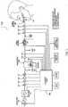
- the airway treatment delivery devicewill typically include a flow generator such as a servo-controlled blower 104.
- the blower 104will typically include an air inlet and impeller driven by a motor (not shown).
- the air inletmay be coupled with a gas supply, such as for oxygen as shown in FIG. 1 , to mix with or supplement the breathable gas supplied by the impeller to the airway of a user.
- the supplementary gas supplymay be introduced through a port, 133, upstream of the humidifier, and/or downstream of the humidifier, through a port 134.
- an air filtermay be provided, such as a HEPA filter, to remove dust or other allergens from the air drawn into the air inlet.
- the blowermay optionally be configured for generating varied flows or pressures.
- the delivered breathable gas flow ratemay be in the range of about -250 to about +250 liters/min, more preferably between about -100 and about 100 liters/min, more preferably, between about 0 to 100 liters/min, more preferably between about 0 and 75 liters/min, yet further more preferably between about 0 to about 50 liters/min with the preferred range being between about 10 to about 35 liters/min, to provide for comfort and efficacy.
- the delivered breathable gas temperaturemay be in the range of about -10°C to about 50°C, more preferably about +4°C to about +45°C, yet more preferably room temperature up to 40°C with the most preferred range being 30°C to 37°C, to provide for comfort and efficacy.
- the delivered breathable gas relative humiditymay be in the range of room humidity up to 100%, for example in the range of about 50% to about 100%, or about 70% to about 100%, or about 80% to about 95%, with the preferred range being 90% to 100%, to provide for comfort and efficacy.
- An absolute humidity rangewill be about 0 to about 82 mg/liter, or more preferably about 27 to about 44 mg/liter.
- the airway treatment device 102will also typically include a patient interface such as an air delivery conduit 106 and nasal prongs or nasal cannula 108 to carry the flow of air or breathable gas to the upper airway of a user of the device or patient.
- the blower 104can be coupled with the air delivery conduit 106 and the nasal cannula 108 so as to provide the breathable gas from the blower 104.
- exhaust gas of the blower and/or expiratory gas from the patient's airwaycan be vented away from the patient interface from a location proximate to the patient's airway or the nares themselves.
- a patient interface that permits such ventingcan provide a comfortable interface for the treatment described herein.
- a patient interface that provides a leak-free seal with the nares of the patientis not required.
- a sealed patient interfacemay be used as an alternative.
- the patient interfacewill typically be held in place proximate or inside the nares of the patient.
- a harness 110may be optionally provided for this purpose.
- a nasal or septum clip and/or adhesivemay also be provided to maintain the nasal cannula in a desired position for use. Examples of suitable embodiments of the patient interface are disclosed in U.S. Patent Provisional Patent Application No. 61/058,659, entitled “Unobtrusive Interface Systems," filed on June 4, 2008 , the disclosure of which is hereby incorporated herein by cross-reference.
- the nasal cannulamay also or alternatively include ear attachment portions connected with the nasal cannula to ensure positioning of nasal cannula by or in the nares during treatment.
- cannula arms extending over and/or around the ears from the nasal cannulamay be utilized.
- the delivery conduitmay be incorporated with such cannula arms, which may alternatively be designed to run under the ears rather than over the ears to reduce noise that might otherwise be heard by the user from the flow of gas through the delivery conduit.
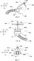
- the patient interface or cannulamay be implemented with a nasal dilator, such as an internal or external nasal dilator. Illustrations of example embodiments are shown in FIGS. 8 to 11 .
- dilator extension members 882R, 882Lproject from a patient interface such as a portion of a cannula 808 body.
- the extension membersmay project from prongs 880R, 880L of the cannula 808 as illustrated in FIG. 8 .
- the prongsserve as dilator mount portion of the cannula or patient interface.
- extension members 8are sized to project inside nares of a patient's nose even if the prongs 880L, 880R also do not extend within the nares.
- Such extension membersmay then be formed or shaped to ply an expansion force against an internal surface of each nare. This expansion force, which is illustrated by the arrows in Fig. 8 , permits the extension members to assist with keeping the nasal passages dilated from inside the nares.
- the extension membersmay be formed of a material that is flexible and resilient to provide a dilation force.
- these extensionsmay otherwise be configured with one or more spring elements (not shown) to provide a suitable expansion force with more rigid extension members.
- the extension members of the patient interfacemay be formed to ply an expansion force from an exterior surface of a patient's nares.
- FIGS. 9-11An example of such an embodiment is illustrated in FIGS. 9-11 .
- the extension members 982may comprise a dilator strip or strips.
- a portion of the patient interface or cannula 908may include a bridge support 990.
- the bridge supportmay be flexible for adjustment so that it may conform to the nose shapes of different patients.
- the bridge supportmay extend from the cannula so that the bridge support is proximate to a ridge area of a patient's nose.
- the supportmay then serve as a dilator mount portion to permit the dilator extension members to be mounted thereto and positioned proximate to the exterior surface of the patient's nose.
- the bridge support 990may optionally include a gap or clip so that a disposable dilator strip may be releasably retained by the bridge support 990.
- a disposable dilator stripmay be inserted or coupled to the bridge support for use.
- Such a dilator stripmay then be a flexible and resilient material so as to permit placement at opposing external surfaces of the nose of the patient and yet still be able to ply the expansion force at those surfaces to assist with dilation of the nares by pulling at the exterior surfaces of the nose.
- these stripsmay also typically include an adhesive so that a surface of the dilator strip may adhere to opposing exterior surfaces of the nose.
- a left side dilator strip 982L and a right side dilator strip 982Rmay then be adhered to the left and right sides of the patient's nose respectively.
- the extension membersmay serve the purpose of securing the cannula or patient interface in a suitable position for providing a flow to the nares of the patient with prongs 980, 980R, 9080L as well as providing a dilation force to assist with keeping the patients nasal passages open during a use of the patient interface.
- additional components of the patient interfacemay be provided for further securing of the cannula in the desired position for use, such as the cannula arms previously discussed.
- the extension members 982L, 982Rmay be more permanently constructed with the bridge support by, for example, forming the dilator strip as an incorporated portion of the patient interface or bridge support of the cannula 908.
- a suitable adhesivemay be re-applied to the nasal surface sides of the attached or incorporated dilator strip.
- an optional spring element 996may also be provided with the dilator strip.
- the spring elementwhen coupled with the extension members, may serve to provide the expansion force with the extension members 992R, 992L.
- a wire or other resilient componentmay serve as the spring element.
- the patient interfacemay also include one or more swivels.
- a swivel 994can permit the patient interface or cannula 908 to remain in a desirable position for directing the flow to the nares of the patient if a patient moves during sleep.
- a swivelprovides relative movement between an air delivery portion of the patient interface and a delivery tube portion of the patient interface.
- one or more swivelsmay permit relative rotation between a cannula 908 and delivery tube 906 about one or more different axes (illustrated as perpendicular axes X, Y, Z). As illustrated in the embodiment of FIG.
- a swivelmay permit a rotation of the cannula 908 with respect to the delivery tube 906 along arrows S1 or about an imaginary X axis. Such movement can permit an air delivery portion of the cannula (e.g., prongs 980) to vertically rotate with respect to the delivery tube 906.
- an air delivery portion of the cannulae.g., prongs 980
- a swivel 994may permit a rotation of the cannula 908 with respect to the delivery tube 906 along arrows S2 or about an imaginary Y axis. Such movement can permit an air delivery portion of the cannula (e.g., prongs 980L, 980R) to horizontally rotate with respect to the delivery tube 906.
- an air delivery portion of the cannulae.g., prongs 980L, 980R
- a swivelmay permit a rotation of the cannula 908 with respect to the delivery tube 906 along arrows S3 or about an imaginary Z axis. Such movement can permit an air delivery portion of the cannula (e.g., prongs 980L, 980R) to tilt rotation with respect to the delivery tube 906.
- an air delivery portion of the cannulae.g., prongs 980L, 980R
- Breathable gasis supplied to the patient by a blower (104 of FIG. 1 ), which may be integrated with other elements of the apparatus, or from a reticulated source, or from bottled gas, or otherwise.
- the airmay be filtered at the input to the blower (104) or at some other point in the gas flow path.
- the apparatusmay also include a humidifier and/or heater (112, 111) and a delivery tube heater (135) (or apparatus to regulate heat loss from the delivery tube 106).
- insulation materialmay be provided on the tube to prevent the heat from the tube from bothering the patient or otherwise being transferred to the skin of the patient.
- Such a tubemay be wrapped with an insulating material or the tube material may be selected for is insulation properties.
- the delivery tubemay be increased in thickness to provide or increase its insulating effect.
- the heater device 111may be exposed to a water mass and/or to the breathable gas flow.
- the humidifier devicemay include a reservoir or fluid circuit for passing the breathable gas through or proximate with a fluid or vapor of the reservoir or fluid circuit.
- One or more heating elementsmay be provided to warm the fluid to create the vapor and/or to warm the breathable gas by convection.
- the warming devicemay further include a pump for circulating fluid within the reservoir or a fluid circuit of the patient interface or blower.
- the apparatusmay also include humidity sensors (117, 121, 134), and/or temperature sensors, and/or a flow rate sensor, and/or pressure sensors.
- the sensor(s)generate temperature and/or humidity signals and/or a flow rate signal, and/or pressure signals (illustrated in FIG. 1 ) for controlling the humidifier and/or heater and/or tube heater using control logic (120) to maintain the temperature and/or humidity of the breathable gas delivered to the patient.
- this devicecan be controlled to alter the temperature and humidity of the breathable gas such that the delivery conditions are within the acceptable or preferred ranges as stated above.
- two air streamsmay be provided, namely a first relatively dry air stream in one flow channel, and a second relatively moist air stream in another flow channel.
- FIG. 2Awhen the flow gate is in one position, it directs flow from the blower to a path that provides for one desired level of temperature and humidification of the breathable gas, and in an alternate position directs flow from the blower to another path that provides a significantly different level of temperature and humidification of the breathable gas, optionally with no humidification.
- the flow gatemay be controlled to switch flow direction in response to breathing cycle phase, or otherwise under control of the controller 120.
- the flow gatemay be controlled to activate to a position that allows the splitting or mixing of the flow between the two paths.
- the controllermay adjust the flow gate to mix variable amounts of gas of two distinct flow paths at two different humidity and/or temperature settings, which may be separately controlled by readings from two additional and different sets of sensors.
- Another version of the flow gate that allows for mixing of flowsis illustrated in FIG. 2B with a controllable iris valve.
- Other mechanisms of generating and mixing flows of different temperatures and humidities, such as dual blower supply,may be used.
- a lower humidity and/or temperature gasmay be delivered during patient expiration and a higher humidity and/or temperature gas may be delivered during patient inhalation.
- a higher humidity and/or temperature gasmay be delivered during exhalation.
- flow control of the humidity of the breathable gas delivered to the patientcan generate high temperature and/or humidity delivery only when the patient requires such for therapeutic reasons, for example during an inhalation phase of a breathing cycle.
- This controlled deliveryin turn may allow for a reduction in the power and/or water requirements of the apparatus over the duration of a therapy session.
- Detection of the phases of the respiratory cycle of the patientmay be based on an analysis of data from an appropriate sensor such as the sensors discussed in more detail herein.
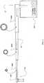
- the delivery conduit 406A, 406B, 406C from the airway treatment devicemay be formed with a gas delivery channel that has a decreasing cross section or diameter.
- a reduction in the cross section diametercan reduce the impedance of the delivery tube and may also reduce heat loss.
- an internal airflow channel GC of the delivery conduitdecreases from at least one larger cross sectional area portion shown as delivery conduit 406A to at least one smaller cross sectional area portion shown as conduit 406B to a yet smaller cross sectional area portion shown as delivery conduit 406C proximate to the nasal cannula 408.
- the tube diameter proximal to the patientcan be smaller than with a constant diameter tube.
- the tube section 406A, and optionally 406Bmay be heated (not shown) to control the breathable gas temperature and/or humidity to a level that allows for the change in temperature of the breathable gas through 406C such that the delivered gas to the patient is within the desired range.
- the small tube section of 406Creduces the heat transfer between the breathable gas and the environment compared with the larger sections of 406B or 406C.
- cross sectional area of any portion of the airflow channelwould typically be smaller than the cross sectional area of the airflow channel of the upstream portion of the delivery conduit.
- transitions between these different cross sectional portions of the delivery conduitmay be made by gradual blending at or near their intersections. Additional tube portions may be interposed between 406A and 406B to provide for more gentle transitions in diameter.
- the end portion of the delivery conduit near the flow generatormay have an internal airflow channel cross section diameter of about 8-15 mm.
- Such an embodimentmay also end with an airflow channel having a cross sectional area diameter of about 3-6 mm proximate to the nasal cannula.
- Such a delivery conduitmay optionally be formed as a foam silicone tube to provide improved thermal insulation properties.
- the airway treatment delivery devicemay optionally include one or more flow sensors 116.
- flow through the nasal cannula 108may be measured using a pneumotachograph and differential pressure transducer or similar device such as one employing a bundle of tubes or ducts to derive a flow signal.
- a pneumotachograph and differential pressure transducer or similar devicesuch as one employing a bundle of tubes or ducts to derive a flow signal.
- the flow sensoris illustrated in FIG. 1 in a location proximate to the blower, the flow sensor may optionally be located closer to the patient, such as in the patient interface or nasal cannula 108.
- the airway treatment devicemay also optionally include one or more pressure sensors 114, 131, such as a pressure transducer.
- the pressure sensor(s) 114, 131can be configured to measure the pressure generated by the blower 104 and/or supplied at the nasal cannula or patient airway.
- the pressure sensors 114, 131are proximate to the blower and located downstream of the blower proximate to the patient interface.
- one or more pressure sensorsmay be located in the prongs or body of the nasal cannula.
- the pressure sensor(s) 114, 131generates a pressure signal(s) indicative of the measurement(s) of pressure at its particular location. Such a signal(s) can be utilized in settings or calculations of the device.
- the pressure sensor 114has only been shown symbolically in FIG. 1 since it is understood that other configurations and other components may be implemented to measure the pressure associated with the blower 104.
- the pressuremay be deduced from knowledge of the blower performance characteristics and the operating blower current and/or voltage and/or rotational speed and/or flow rate.
- different groups of sensorsmay be provided for a delivery tube associated with each nare of the nasal cannula.
- a delivery tube for each naremay include a pressure sensor and/or flow sensor so that independent measurements of flow and/or pressure may be measured for each nare.
- the airway treatment devicemay also include one or more temperature sensors as previously mentioned.
- such sensorsmay be located to measure the heater(s) 111, 135, and/or the treatment gas at various locations in the delivery tube such as near the blower (e.g., before or after), after the humidifier and near the patient.
- the treatment devicemay also include one or more humidity sensors as described above. Thus, humidity may be measured before and/or after the humidifier and near the patient. Additional such sensors may be employed when multiple flow channels are utilized such as in the embodiments of FIGS. 2A and 2B for more measuring of the conditions of the distinct portions of the tubes. Still further sensors may also be configured to measure ambient humidity and temperature.
- the signals from the various sensorsmay be sent to a controller or processor 120.
- Optional analog-to-digital (A/D) converters/samplersmay be utilized in the event that supplied signals from the sensors are not in digital form and the controller is a digital controller.
- the controllermay in turn generate blower control signals.
- the controllermay generate an RPM request signal to control the speed of the blower 104 by setting a desired frequency or rotational velocity set point and comparing it with the measured condition of a frequency or velocity sensor.
- such changesmay be based on determining a desired flow set point and comparing it with the measured condition of the flow sensor.
- such changes to the motor speedare accomplished by increasing or decreasing supplied motor current with the servo based on determined differences between set and measured conditions such as in a closed loop feedback fashion and translating the difference to current.
- the processor 120 or controllermay make controlled changes to the flow delivered to the patient interface by the blower 104.
- changes to flowmay be implemented by controlling an exhaust with a mechanical release valve (not shown) to increase or decrease the exhaust while maintaining a relatively constant blower speed.
- the controller or processor 120is typically configured and adapted to implement particular control methodology such as the methods described in more detail herein.
- the controllermay include integrated chips, a memory and/or other control instruction, data or information storage medium.
- programmed instructions encompassing such a control methodologymay be coded on integrated chips in the circuits or memory of the device or such instructions may be loaded as software or firmware using an appropriate medium.
- the apparatuscan be used for many different open airway treatment therapies, such as the flow treatments previously mentioned, by adjusting a flow delivery equation that is used to set the speed of the blower or the exhaust venting by an optional release valve (not shown).
- flowmay be set to desired levels as set by the switches of the device and optionally increased in response to detected respiratory conditions such as an apnea, hypopnea, or airway resistance.
- the flow ratemay be kept substantially constant over the phases of respiration.
- the generated flowmay be kept generally constant over the respiratory cycle and provide some end expiratory relief.
- the flowmay be varied smoothly to replicate the patient's detected respiration cycle.
- indications of upper airway obstruction determined by the controllerare servo-controlled by varying the flow rate and/or level of humidification and/or temperature.
- a device in accordance with the technologymonitors the patient for signs of partial or complete upper airway obstruction. Upon detection of partial upper airway obstruction, and according to the severity and frequency of such events, the level of humidification is increased. In some embodiments, if the partial airway obstruction is eliminated, or not detected, the level of humidification may be reduced. Similarly, if partial airway obstruction is detected, flow may be further increased.
- indications of the need to vary treatmentare derived from a pressure signal that is in turn used to infer patient flow in the controller 120.
- the inferred flow estimateis applied to automatic pressure control algorithms such as those described in U.S. Patent No. 5,704,345 , the entire contents of which are hereby expressly incorporated by cross-reference.
- the output of the automatic pressure algorithmsis however, in one embodiment, used to control the flow rate and/or level of humidification and/or temperature.
- pressureis used directly by the controller to determine the presence of partial or complete airway obstruction.
- other non-pressure, non-flow based diagnostic techniquesare used, such as movement of the suprasternal notch, patient movement, sympathetic nervous system activation (e.g. sweating, skin resistance, heart rate), pulse oximetry, EEG and ECG.
- sympathetic nervous system activatione.g. sweating, skin resistance, heart rate
- pulse oximetrye.g. EEG and ECG.
- the controllermay determine a tidal volume or inspired volume of air or gas by the patient during treatment. Such a determination may be used for setting the pressure or flow and/or analyzing conditions of the patient's airway or respiration.
- the patient interfacemay seal with the patient nares but have a pre-determined venting characteristic, or one that may change as a function of the pressure or flow rate setting of the flow generator.
- the volume of leakmay be determined by a look-up table or calculation by the controller 120 based on the settings of the flow generator.
- the apparatuscan be combined with additional components like accessories, which may be attached to pre-defined interfaces or using the shape of the embodiment, openings, screw holes, or other coupling methods or prominent areas of the apparatus to attach.
- accessoriescan be for example additional filters, or sound dampening mechanisms, or data logging electronics, which may have for example either a mechanical, pneumatic, magnetic and/or electrical connection to the apparatus. The connection and interaction may also be wired so that the accessories work together with the apparatus from a distance.
- a chargeable battery packas illustrated in FIG. 3 .
- the airway treatment device of this embodimentmay be implemented with a DC battery sufficient to permit at least a use for a single sleep session without connection to an AC power outlet.
- a dock 333such as a cradle with a docking port charger that may be releasably coupled with a charging port of the respiratory treatment device 302, provides a convenient way to charge the battery of the respiratory treatment device 302.
- a noise sensor or microphonemay be provided to detect levels of noise generated by the blower or the patient interface. Noise measurements may be made and an increase in ambient noise (e.g., a level of sound after filtering out frequencies such as the frequencies that may be associated with snoring) may be responded to by the controller 120 changing a motor speed in attempt to reduce the noise. However, the controller may further reject such changes to the extent that any change would prevent a minimum desired level of treatment from being generated by the flow generator for the patient.
- the humidification apparatusmay comprise an arrangement whereby a mass of water is required to be increased or decreased in temperature. This, in turn, may result in some delay between the change in the heater state and the humidity and/or temperature of the breathable gas delivered. When such a delay prevents the desired combination of flow, temperature and humidity to be met in the delivered gas, it may be desirable to prioritize the properties that are to be met for therapeutic, comfort or functional reasons. For example, it may be desirable to ensure that humidity is within the preferred range as the first priority, temperature is within the preferred range as the second priority, and flow is within the preferred range as the third priority.
- the flow rate Fminis a small flow of about 5% - 35% of the desired therapy flow - sufficiently large to transport the breathable gas to allow sensing and control, but sufficiently small to ensure that the patient does not suffer any discomfort as a consequence of the delivered sub-optimal breathable gas.
- this sequencemay be initiated conditionally upon, and/or triggered by, detection of a patient connected to the apparatus.
- detectionmay be by observation or detection of fluctuations in pressure and/or flow signal(s) and other techniques such as those described in U.S. Patent No. 6,240,921 (ResMed Limited), the contents of which are hereby expressly incorporated herein by cross-reference.
- control of the flow to meet the desired delivered breathable gas property rangesit may also be desirable for the patient to control the flow of the apparatus in a manner that allows the flow rate to increase in accordance with a selected rate.
- Such controlmay offer advantages in acceptance and compliance of such therapy because the patient is able to become accustomed to the therapy over a longer time than would be the case without such rate control.
- This start-up strategymay be applied for a cold-start or a warm-start.
- an example algorithmmonitors the temperature and humidity delivered at the patient interface (either directly or calculated from other inputs), for example by means of temperature and humidity sensors 132 and 134, and ramps up the temperature as quickly as possible to the desired range (while maintaining relative humidity (RH) within the desired range). Then the flow rate is increased from the initial value to the desired value in accordance with the user ramp setting such that the delivered temperature and humidity are maintained within the desired ranges.
- RHrelative humidity
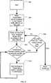
- the start-up proceduredetermines if the apparatus is in a cool-down mode. If the result is affirmative, the flow rate is maintained in 504. Otherwise, a minimum flow rate will be set in 506.
- Processmoves to 510 where the flow of the apparatus is controlled to meet the target or set point. The method then proceeds to 512 where the relative humidity (RH) is measured and compared to a desired range or deviation of the target or set point for relative humidity. If the result in 512 is negative then the process proceeds to 514 to control the humidity related elements of the apparatus to the set point or target for relative humidity. The process then advances to 510 to control the breathable gas flow rate.
- RHrelative humidity
- processadvances to 516.
- the breathable gas temperatureis checked to see if it is within a desired range or deviation from the target or set point value. If the result in 516 is negative then the process proceeds to 518 to control the temperature related elements of the apparatus to the set point or target for temperature. The process then advances to 510 to control the breathable gas flow rate.
- the processproceeds to 520.
- the flow rateis checked to see if it is below a desired range or acceptable deviation from the therapy target flow rate. If, in 520, the result is negative then the process is complete. If, in 520, the result is affirmative then the process advances to 522.
- the flow rateis measured or calculated to determine if a step increase in the rate is appropriate for ramping up of the flow rate. If the step increase would raise the flow rate above the therapy target, then process flows to 524 and 510 without an increase in the target set point of the flow rate for the warm-up process.
- the target set pointis incremented to increase or ramp up the flow rate in 526 and then controlled in 510 at the new stepped-up flow rate. In this way, the ramping of flow rate may be governed without allowing the humidity or temperature to deviate from their desired or target set-points.
- FIG. 6Another example start-up procedure algorithm is illustrated in FIG. 6 .
- the start up procedurebegins.
- the temperature (and/or humidity) of one or more heating elementse.g., humidifier heating element
- a ramp-up procedure for the flow generatorbegins in which an incremental increase in the flow rate will be set over toward a maximum, such as by setting an incremental increase in the RPM set point of the blower every several minutes.
- the temperature and/or humidity levelsare checked with the appropriate sensors to determine if the temperature and humidity is within an acceptable deviation margin of the set point after an increase in the blower flow rate.
- the processwill flow to 609 to check if the ramp-up of flow has reached the target therapy level for the treatment session. If not, then the process returns to 606 to again increment the flow generator according to the ramp-up procedure and its time adjustment period. If, in 609, the therapy level has been reached, the warm-up process is complete and the therapy session protocol may begin.
- the marginse.g., a margin of +/- 1, 2, 3, 4 or 5 degrees of the temperature setting or +/- 1, 2, 3, 4 or 5% relative humidity of the humidity setting
- the measurement/comparison processflows to 610 to wait a period of time. Process then returns to the comparison process of 608 to again check the temperature and/or humidity sensors for compliance with the deviation margin. In this way, the flow rate of the apparatus may ramp up in a comfortable fashion to the therapy flow rate setting while maintaining the desired set points for the humidity and/or temperature of the gas delivered by the apparatus.
- a patientmay desire a temporary decrease in the flow rate to permit the patient to more comfortably fall asleep with a lower flow rate before the flow rate would then return to a higher prescription or therapeutic level during sleep.
- a re-ramp methodologymay be implemented by the controller.
- the apparatusmay permit the user to activate the re-ramp procedure by a switch, button, knob or other user interface of the apparatus.
- the apparatusupon activation of the procedure, the apparatus would lower the flow rate for a predetermined period of time.
- the period of timemay optionally be adjustable by the user with an input device of the apparatus. At the conclusion of the period of time the flow rate may then return to the therapeutic level.
- the re-ramp algorithm or methodology of the apparatusmay only permit the re-ramp feature to be activated after the apparatus has achieved a warmed-up state, such as if the apparatus has already completed the warm-up procedure previously described.
- the re-ramp featuremay be disabled if the apparatus has achieved a cool down state such as at a time after completing a cool-down methodology or when the apparatus is performing a cool-down methodology as described in more detail herein.
- the methodology of the re-ramp featuremay be implemented as a function of humidification and/or temperature or a humidification state and/or temperature state of the apparatus.
- the apparatusmay then be re-activated by execution of the warm-up methodology previously described rather than the re-ramp procedure.
- the selection of the rate for the reduced flow during the re-ramp proceduremay be user adjusted or selected with an input device or user interface of the apparatus.
- the reduced flow ratemay be a function of humidity and/or temperature such that the reduced flow rate selection is at least partially set in a manner that prevents condensation from forming in the patient interface and/or delivery tube.
- the algorithmmay monitor the temperature and humidity internal and/or external to the apparatus, for example by means of temperature and humidity sensors, and then automatically select a reduced flow rate, such as from a look-up table based on the temperature and/or humidity information.
- the reduced flowmay be implemented without a blower speed change by the flow generator.
- an exhaust vent or release valvewhich may be a mechanical valve that is controlled by a processor or controller of the apparatus, may be opened to vent part of a humidified gas supply from the blower so that only a portion of the humidified flow generated by the flow generator is directed to the patient interface. In this way, a lower humidified flow rate may be delivered to the patient for the re-ramp procedure.
- the vent or release valvemay then close, such as gradually over a period of time that is typically longer than several breaths, to return the humidified flow to the therapeutic rate.
- a release valve or exhaust ventmay, for example, be positioned to exhaust gas flow generated by the blower 104 at a position in the air deliver circuit after the humidifier 112.
- the immediate power-down of the apparatusmay lead to condensation in the apparatus - particularly the tube - because the heated water mass will continue to emit vapor and so the regions where the breathable gas path is in thermal contact with the environment, for example the tube walls, may cool rapidly.
- the presence of condensation in the apparatuswill adversely affect the comfort and/or function of the apparatus at a subsequent start-up, because droplets may be blown down the tube to the patient interface causing patient discomfort, and/or the presence of water in the heated tube may lead to additional humidification in the breathable gas delivered to the patient or otherwise affect the ability of the system to control the breathable gas delivery at the patient interface within the desired ranges.
- An aspect of the current technologyis a control methodology that may be optionally used with the apparatus to control the rate of cooling of the apparatus - especially the tube - to diminish the likelihood of significant condensation forming during apparatus power-down.
- Such a strategyincludes implementing a sequence of apparatus states or transitions to promote the maintenance of the temperature of the breathable gas in the system above the local dew-point temperature.
- this sequencemay be initiated conditionally upon, and/or triggered by, detection of the absence of a patient connected to the apparatus. Such detection may be by detection of fluctuations in pressure and/or flow signal(s).
- the initiation of this sequencemay be delayed by a predetermined period, which may be patient-selectable, following such triggering, to allow for temporary disconnection and reconnection of the apparatus.
- the predetermined periodmay be about 1 - 30 minutes.
- the flow rate Fmin1may be about 50% - 150% of the typical therapy flow.
- the flow rateneeds to be sufficiently high to promote cooling of the water mass but not so high so as to generate obtrusive noise.
- This flow ratemay be a fixed value, a value that is directly or indirectly selected by the user, for example should a rapid cool-down be desired, and/or a variable value that follows a profile with time, or with a sensed breathable gas property value such as humidity.
- the flow rate Fmin2is a small flow of about 5% - 35% of the typical therapy flow - sufficiently large to transport the breathable gas to allow sensing and control, but sufficiently small that the humidification of the breathable gas is low and does not cause condensation when the apparatus is subsequently powered-down.
- the transition in flow rate from Fmin1 to Fmin2may be controlled to a predetermined profile.
- Fmin2may be a fixed value, a value that is directly or indirectly selected by the user, for example should a rapid cool-down be desired, and/or a variable value that follows a profile with time, or with a sensed breathable gas property value such as humidity.
- This cool-down strategyapplies to any mode or phase of operation of the apparatus.
- a pause to therapymay be requested by the user such that the breathable gas conditions are maintained for a short period, for example 1 - 30 minutes, and if therapy is not restarted within this period, either manually or by the detection method above, then the cool-down strategy will be initiated.
- the algorithmmonitors the temperature and humidity delivered at the patient interface (either directly or calculated from other inputs), for example by means of temperature and humidity sensors 132 and 134, and ramps down the humidity as quickly as possible until such time as the system humidity is stable, whilst maintaining an acceptable dew-point margin, for example about a 2-5°C margin.
- the margincan be determined from the Saturation Vapour Pressure at the flow temperature, for example using the formulas in ISO Standard 8185 2007.
- the flow rateis decreased from the initial value to the Fmin2 in a manner that allows the maintenance of the dew-point margin.
- the apparatusmay then be powered-down.
- the algorithm of FIG. 7may be summarized as follows.
- 702after the treatment therapy controlled by the apparatus is stopped, humidity generation with the humidifier is stopped.
- the flow rate generated by the flow generatoris controlled to the Fmin1 target value.
- 706one or more of the heating elements are controlled to maintain a target temperature in the delivery tube of the patient interface.
- a dew-point temperatureis checked to assess if it has stabilized. If it has not, process flow returns to 704. If it has, process flows to 710.
- the flow rate of the flow generatoris then controlled to the target Fmin2 value.
- 712one or more of the heating elements are controlled to maintain a target temperature in the delivery tube of the patient interface.
- a dew-point temperatureis checked to assess if it has stabilized. If it has not, process flow returns to 710. If it has, process flow of the cool-down procedure is complete.
- a userwill be titrated to determine the optimal flow rate and temperature for treating the user's sleep disordered breathing (SDB).
- the optimal settings for flow rate and temperatureare those that maximize efficacy of the therapy as well as user comfort.
- the temperaturewill be set to the highest value within the range capable by the device that is deemed comfortable by the user.
- the temperaturemay also be changed to compensate for any droplets of water that may form in the air delivery tube or user interface, for example nasal cannula.
- the temperaturemay also be changed to maximize the efficacy of the therapy.
- For flowan example would be for the rate of flow to start at the lowest possible by the device.
- the flow rateWhen the user is asleep and SDB events are detected, such as by the controller of the device, the flow rate would be incrementally increased in response to the SDB events (for example, apneas, hypopneas, flow limitation and snoring) to prevent them from repeating and hence maximizing the efficacy of the therapy. Another method would be to set the flow rate to the highest rate that is comfortable for the user when awake. When the user is asleep, the necessary changes in flow rate may be made in response to the SDB events, again to maximize the efficacy of the therapy.
- SDB eventsfor example, apneas, hypopneas, flow limitation and snoring
- Changes to flow rates and temperaturemay be done manually, by an observer of the user when they are asleep. For example, by a sleep technologist observing the user using polysomnography (PSG).
- PSGpolysomnography
- Changes to flow rate, gas temperature and/or humidity levelsmay also occur automatically in response to the SDB events detected by the apparatus. This would be based on an algorithm that incrementally increases the flow rate, gas temperature and/or humidity levels in response to the SDB events. The magnitude of the increase would be governed by the type of the SDB event. For example, the increase in flow rate, gas temperature and/or humidity levels would be greater for an apnea compared to flow limitation which in turn would be greater than the response to snore. Alternatively, incremental decreases in the flow rate, gas temperature and/or humidity levels would occur in response to an absence of detected SDB events after a certain period of time.
- the settings of flow rate, humidity and/or temperaturemay be increased or decreased by the device with some step value by simply detecting whether any one or more of these SDB events occur. Moreover, such adjustments may be a function of the measure of the detected SDB event.
- a measure of partial obstructionmay be a varying index from 0 to 1 where 1 is fully obstructed, 0 is not obstructed and 0.5 if half obstructed.
- the change in any of the flow rate, humidity and/or temperaturemay then be a function of the degree of partial obstruction, such as, a function that generates a greater adjustment when there is a larger degree of obstruction and a lesser adjustment when there is a smaller degree of obstruction.
- a degree of partial obstructionmay be assessed by a flattening analysis of a respiratory flow signal, a roundness analysis of a respiratory flow signal and/or other partial obstruction methodology for assessing of the patient's upper airway.
- the ratio of the outer diameter of the nasal prongs of the patient interface to the surface area of user's naresmay be increased or decreased. These changes would be to increase the efficacy and comfort of the therapy.
- the patientmay alter the therapy settings manually within a restricted range to improve comfort according to personal choice.
- the flow and or humidification of air delivered to each nareis individually controlled. For example, a higher flow and/or more humidification may be delivered on one side compared to the other.
- each of the air flow & humidificationmay be individually cycled in a nare.
- a flow ratemay be adjusted in one nare while maintaining a fairly constant flow rate or humidity in the other nare.
- a high flow ratemay alternate between the left nare and a right nare such that when a high rate is directed at one nare, a low rate is directed at the other.
- changes in flow and/or humidification of air delivered to one nareare synchronized with changes in flow and or humidification of air delivered to the other nare.
- the delivery of a higher flow to one nare compared to the othermay be to compensate for a user with unilateral nasal obstruction.
- the higher flow ratewould be delivered to the nare that was not obstructed. This would maximize the efficacy of the therapy.
- a higher ratemay be delivered to the obstructed nare as an attempt to decrease the obstruction.
- Obstructionmay be determined by automatic method of detecting partial obstruction, for example, by analysis of a respiratory flow signal. Such an analysis may be independent for the respiratory flow signal associated with each nare.
- unilateral partial obstructionmay be detected by an increase in a measure of pressure from a pressure sensor associated with one nare with respect to a measure of pressure of another pressure sensor associated with the other nare.
- the delivery of more humidification to one nare compared to the othermight be to compensate for the higher flow being delivered to one nare because it is less obstructed.
- more humidificationmay be delivered to the nare with higher nasal resistance to reduce this resistance.
- a higher flowmay be delivered to the other nare.
- the humidification and air flowmay then be returned to equal delivery to each of the nares. This may be tested by analysis of the relative pressures of the sensors associated with each nare. For example, the flows directed at each nare may be set to be equal and the two pressures associated with the nares may then be checked and compared for substantial equality, which may indicate that there is no unilateral obstruction.
- This delivery of different flowcan be achieved, for example, by the use of two motors within the device.
- One motor for each of the two nareswith a controller linking both motors.
- a single motor blowermight be used with controlled venting valves in the flow paths for each nare.
- the blowermay be set to a desired rate for the highest flow desired for either nare.
- the flow at the high ratemay be delivered to one nare without substantial venting while the blower flow rate to the other nare may be reduced by venting some of the flow of the flow path of the other nare without delivering all of it to that nare.
- one or more variably controlled gate valvesmay split a single supply tube from a blower into a y-junction.
- mechanical gate valves, near a y-junctionmay then be set to position(s) to gate a portion of the flow to one delivery tube directed at one nare and a portion of flow into another delivery tube directed at the other nare.
- 60% of the flowmay be directed to one nare and 40% of the flow may be directed at the other nare.
- the gate valvemay be controlled to divide the supply rate by other percentages (e.g., 50%/50%, 0%/100% etc.) Essentially, the controller can set the gate valve to divide the flow between the nares by any desired position or aperture setting.
- An example of suitable gate valvesmay be comparable to the gate valves illustrated in Figs. 2A or 2B but with the flows traveling in the opposite direction from that illustrated in those figures.
- additional tubes and gate valvesmay also be added to then adjust the humidity levels directed to each nare tube as previously described with regard to FIG. 2A and 2B .
- the delivery of different levels of humidificationcan be achieved, for example, by altering the proportion of air being delivered that comes from the humidifier compared to that from the environment. By increasing the proportion of air from the environment the lower the amount of humidification being delivered to the patient.
- ambient humidification and temperature sensorsmay be utilized to provide the controller with data concerning these ambient conditions.
- a dual rate mode of operationmay be employed.
- the deviceis triggered by the inspirational flow of a user, in particular by the flow rate provided at the beginning of inspiration.
- This flow ratemay be detected by inference from the pressure signal, or otherwise, and compared to a predetermined threshold.
- the thresholdmay be set to different sensitivities, e.g. high, medium and low.
- the inspiration flow rateis higher than the expiration flow rate. This is a form of expiration flow relief that may improve the comfort of the therapy.
- the expiration flow rateis higher than the inspiration flow rate. This may assist in further increasing the end expiratory pressure (EEP) in the upper airway of the user. By increasing the EEP, the efficacy of the therapy may be improved.
- EEPend expiratory pressure
- triggeringmay also be utilized to implement first and second distinct humidification levels or first and second distinct breathable gas temperatures according to the detected phases of the patient's respiratory cycle.
- the controllermay set different gas temperatures and/or different humidification levels depending on the phase of respiration.
- the therapeutic mode described hereinmay be implemented in a device also capable of delivering CPAP or APAP therapy.
- the mode of therapy delivered by the devicemay be changed through a button, dial, menu or other control.
- a change of therapeutic modemight also be associated with changing the air-delivery circuit to that appropriate to the therapeutic mode.
- the devicemay have an indicator, for example an LED, which will illuminate when the device believes it is not satisfactorily treating the SDB of the user based on data logging.
- the LEDwould be illuminated when the device recorded SDB events were above a predetermined threshold at the end of a session. This threshold could be set based on the requirements of the treating physician.
- An example of a thresholdwould be an apnea and hypopnea index (AHI) greater than 5 per hour of use.
- CPAPcontinuous positive airway pressure
- APAPautomatic positive airway pressure
- the indicator described above in one casemay result in the device of the user being changed to a CPAP/APAP device.
- itmay indicate that the mode of therapy being delivered by the device be switched, manually, to CPAP/APAP mode.
- the devicewould be capable of delivering both types of therapy (i.e., that described in this document and CPAP/APAP).
- the indicatormay lead to an automatic change of therapy mode and the device which is capable of delivering both types of therapy automatically makes the change. The indicator in this instance would be to notify the user that the change had occurred.
- the relatively high flow rates of the devices and systemsmay give rise to additional problems relating to patients experiencing problems wherein the nasal cannula are accidently dislodged during operation. These problems may include potential damage to the eyes or face of the patient wherein the high flow rates of air are accidently directed to sensitive parts of the face.
- the preferred system and devicemay also detect accidental dislodgement, wherein the dislodgement is detected by at least one of the aforementioned preferred sensors.
- the system or devicemay be automatically shut off to prevent or limit potential damage from the high flow rates being accidentally directed to sensitive parts of the patient's face.
- the dislodgment detectionmay automatically open a mechanical vent valve controlled by the controller to vent the air at or near the controller or flow generator in a manner that more immediately depressurizes the supply tube to the cannula.
- One example dislodgement sensormay be a pressure transducer that detects a change in pressure as an indication of dislodgement.
- a clip with electrical contacts 1210A, 1210Bmay serve as a dislodgment sensor by sending an electrical switch signal to the controller.
- the clipmay be attached to a portion of the nares, such as at the base of the nose.
- a light spring force used to hold the clip in placemay also be utilized to activate the sensor upon dislodgment.
- the clipUpon removal or dislodgment, the clip may be configured to spring closed (or open depending on its desired configuration). The closing of the contacts (or opening thereof depending on the configuration of the switch and the spring action) may then be detected electrically by the controller as a dislodgment.
- the clipmay even be combined with the other components of the patient interface such as the nasal dilators previously discussed (e.g., the dilator of FIGs. 8 or 11 ), and may even also serve to maintain the cannula in place as described further herein.
- the chance or likelihood of accidental dislodgementmay also be minimized by attaching a specialized clip 1310 onto the nasal cannula.
- the clipmay be constructed of flexible and resilient material (including polyermic materials) and may attach and secure the nares of the patient to the nasal cannula with a retaining force, and may still maintain a non-sealed relationship between the nose and nasal cannula.
- the end of the nasal cannula that may be inserted into the nose during operationmay include an air diffuser such as the example diffuser with radial fins 1440 on the prong 880 illustrated in FIG. 14 .
- the air diffusermay prevent or limit the flow of air in a single direction but increases the dispersion of air exiting the nasal cannula. This may serve as an additional safety feature, wherein the nasal cannula are accidentally dislodged from their position in nares. If the dislodgement occurs, the air diffuser reduces the risk that relatively high flow air will directed into a sensitive region of the patient's face such as the eyes. Even if the air is accidentally directed into the eyes of the patient, the attachment of the air diffuser may significantly reduce the overall flow of air directed into the eyes and thereby increase safety of the device and reduce the overall risks.
- the system or devicemay include a controller that sounds and/or displays an alarm to alert a patient or clinician to the dislodgement.
- the nasal cannula previously described for use with any of the aforementioned embodimentsmay further include noise limiting features. These noise limiting features may reduce the overall noise heard by the patient and people around the patient, wherein the system or device is operational.
- these noise limiting featuresmay include specialized baffles mounted on or in the nasal cannula or prongs to disperse or diffuse any noise emitted by the nasal cannala. This may be particularly true when the nasal cannula are delivering relatively high flow rates when compared to standard closed CPAP devices.
- the noise bafflemay be constructed of a foam insert, a maze-like structure mounted on or proximal to the end of nasal cannula engaging the nares of the patient.
- An example, baffle 1550 about a prong 880is illustrated in FIG. 15 .
- drug deliveryis provided with the supply of breathable gas, for example in the form of a nebulised drug.
- the present systemmay be used for treatment of COPD or Cystic Fibrosis and accompanied with appropriate drugs for the respective diseases.
Landscapes
- Health & Medical Sciences (AREA)
- Pulmonology (AREA)
- General Health & Medical Sciences (AREA)
- Public Health (AREA)
- Anesthesiology (AREA)
- Biomedical Technology (AREA)
- Heart & Thoracic Surgery (AREA)
- Hematology (AREA)
- Life Sciences & Earth Sciences (AREA)
- Animal Behavior & Ethology (AREA)
- Emergency Medicine (AREA)
- Engineering & Computer Science (AREA)
- Veterinary Medicine (AREA)
- Otolaryngology (AREA)
- Orthopedics, Nursing, And Contraception (AREA)
- Radiation-Therapy Devices (AREA)
- Infusion, Injection, And Reservoir Apparatuses (AREA)
- Measurement Of The Respiration, Hearing Ability, Form, And Blood Characteristics Of Living Organisms (AREA)
- Respiratory Apparatuses And Protective Means (AREA)
- Thermotherapy And Cooling Therapy Devices (AREA)
Abstract
Description
- This application claims the benefit of the filing dates of
United States Provisional Patent Application No. 61/059,084 filed June 5, 2008 United States Provisional Patent Application No. 61/117,375 filed November 24, 2008 - The present technology relates to methods and apparatus for treatment of respiratory conditions such as the conditions related to sleep disordered breathing (SDB) (including mild obstructive sleep apnea (OSA)), allergy induced upper airway obstruction or early viral infection of the upper airway.
- Sleep is important for good health. Frequent disturbances during sleep or sleep fragmentation can have severe consequences including day-time sleepiness (with the attendant possibility of motor-vehicle accidents), poor mentation, memory problems, depression and hypertension. For example, a person with nasal congestion may snore to a point that it disturbs that person's ability to sleep. Similarly, people with SDB are also likely to disturb their partner's sleep. One known effective form of treatment for patients with SDB is nasal continuous positive airway pressure (nasal CPAP) applied by a blower (air pump or compressor) via a connecting hose and patient interface. In some forms the supply of air at positive pressure is delivered to both the nose and mouth. The positive pressure can prevent a collapse of the patient's airway during inspiration, thus preventing events such as snoring, apnoeas or hypopnoeas and their sequelae.
- Such positive airway pressure may be delivered in many forms. For example, a positive pressure level may be maintained across the inspiratory and expiratory levels of the patient's breathing cycle at an approximately constant level. Alternatively, pressure levels may be adjusted to change synchronously with the patient's breathing cycle. For example, pressure may be set at one level during inspiration and another lower level during expiration for patient comfort. Such a pressure treatment system may be referred to as bi-level. Alternatively, the pressure levels may be continuously adjusted to smoothly change with the patient's breathing cycle. A pressure setting during expiration lower than inspiration may generally be referred to as expiratory pressure relief. An automatically adjusting device may increase the treatment pressure in response to indications of partial or complete upper airway obstruction. See
U.S. Patent Nos. 5,245,995 ;6,398,739 ;6,635,021 ;6,770,037 ;7,004,908 ;7,141,021 ;6,363,933 and5,704,345 . - Other devices are known for providing respiratory tract therapy. For example, Schroeder et al. describes an apparatus for delivering heated and humidified air to the respiratory tract of a human patient in
U.S. Patent No. 7,314,046, which was filed on 8 Dec. 2000 and assigned to Vapotherm Inc. Similarly, Genger et al. discloses an anti-snoring device with a compressor and a nasal air cannula inU.S. Patent No. 7,080,645, filed 21 July 2003 and assigned to Seleon GmbH. - It may be desirable to develop further methods and devices for treating upper respiratory conditions.
- A first aspect of the some embodiments of the technology is to provide methods and apparatus for treatment of respiratory conditions.
- Another aspect of some embodiments of the technology is to provide methods and apparatus for treating sleep disordered breathing.
- In one embodiment of the technology, air at a high flow rate is delivered to the nasal passages, preferably in the range of about 10 to about 35 litres/minute.
- In another embodiment, air is provided with a temperature in the range of about 30°C to about 37°C.
- In another embodiment, air with a high humidity is provided to the nasal passages, preferably with an absolute humidity in the range of about 27 to about 44 mg/litre.
- In another embodiment, methods and apparatus are provided for servo-controlling sleep disordered breathing by varying one or more of flow, temperature and level of humidification.
- Another aspect of the technology is to provide a device for treating respiratory conditions having one or more start-up and/or shut-down protocols that vary any of flow, temperature and level of humidification. For example, the device may provide for ramping any one or more of flow, temperature and level of humidification.
- Another aspect of the technology is to vary any of flow, temperature and level of humidification within, or as a function of detection of, a respiratory cycle of a patient. For example, a device may provide first levels of flow, temperature and/or humidification during inhalation and second or different levels of flow, temperature and/or humidification during exhalation.
- Another aspect of the technology is to provide different levels of flow, temperature and/or humidification to each naris. For example, in one form of device, levels of flow, temperature and/or humidification are cycled between the nares.
- In accordance with the technology, methods and apparatus are provided for varying the levels of flow, temperature and/ or humidification.
- In accordance with the technology, levels of flow, temperature and/or humidification may be varied either manually or automatically.
- In accordance with the technology, levels of one or more of flow, temperature and humidification may be varied over a period having a duration less than, equal to or greater than the duration of a respiratory cycle. For example, flow, temperature and humidification may be increased over several breaths, or decreased over several breaths.
- Another aspect of the technology is to provide an air delivery conduit having a diameter that changes along its length.
- Another aspect of the technology is to provide each naris with individually controlled levels of flow, temperature and/or humidity.
- Additional features of the present respiratory technology will be apparent from a review of the following detailed discussion, drawings and claims. The following aspects are preferred embodiments of the invention:
- 1. A respiratory treatment apparatus comprising:
- a flow generator to produce a flow of breathable gas through a patient interface at a first flow rate;
- a humidifier in a path of the flow to humidify the breathable gas at a first humidity level;
- a processor configured to control automatic adjustments to the first flow rate of the flow generator and to control automatic adjustments to the first humidity level.
- 2. The apparatus of
aspect 1 wherein the processor is configured to control the first flow rate in conjunction with an inspiratory phase of a respiratory cycle and a second flow rate in conjunction with an expiratory phase of the respiratory cycle. - 3. The apparatus of
aspect 1 wherein the processor is configured to control the first humidity level in conjunction with an inspiratory phase of a respiratory cycle and a second humidity level in conjunction with an expiratory phase of the respiratory cycle. - 4. The apparatus of
aspect 1 further comprising:- a heating element in a path of the flow to heat the breathable gas at a first temperature level,
- wherein the processor is further configured to control the first temperature.
- 5. The apparatus of aspect 4 wherein the processor is configured to control the first temperature level in conjunction with an inspiratory phase of a respiratory cycle and a second temperature level in conjunction with an expiratory phase of the respiratory cycle.
- 6. The apparatus of
aspect 1 further comprising:- a patient interface coupled with the flow generator, the patient interface comprising a first flow path and a second flow path, wherein each flow path is configured to be associated with a nare of a patient,
- wherein the processor is configured to concurrently control the first flow rate through the first flow path and a second flow rate through the second flow path, and wherein the first flow rate and the second flow rate are different flow rates.
- 7. The apparatus of aspect 6 wherein the flow generator comprises at least two blowers.
- 8. The apparatus of aspect 6 wherein the flow generator comprises at least one blower and two flow channels, and wherein each flow channel includes an independent venting valve controlled by the processor.
- 9. The apparatus of aspect 6 wherein the flow generator comprises at least one blower and two flow channels, and wherein a gate valve controlled by the processor regulates a division of flow from the blower to the flow channels.
- 10. The apparatus of
aspect 1 further comprising:- a patient interface coupled with the flow generator, the patient interface comprising a first flow path and a second flow path, wherein each flow path is configured to be associated with a nare of a patient,
- wherein the processor is configured to concurrently control a first flow rate through the first flow path at a first humidity level and a second flow rate through the second flow path at a second humidity level, wherein the first humidity level and the second humidity level are different humidity levels.
- 11. The apparatus of
aspect 1 wherein the processor adjusts the first flow rate in response to the processor detecting one or more incidents of partial obstruction. - 12. The apparatus of
aspect 1 wherein the processor adjusts the first flow rate in response to the processor detecting one or more incidents of apnea. - 13. The apparatus of
aspect 1 wherein the processor adjusts the first flow rate in response to the processor detecting one or more incidents of snoring. - 14. The apparatus of
aspect 1 wherein the processor adjusts the first humidity level in response to the processor detecting one or more incidents of partial obstruction. - 15. The apparatus of
aspect 1 wherein the processor adjusts the first humidity level in response to the processor detecting one or more incidents of apnea. - 16. The apparatus of
aspect 1 wherein the processor adjusts the first humidity level when the processor detects one or more incidents of snoring. - 17. The apparatus of
aspect 1 wherein the processor comprises a warm-up procedure that sets a temperature of the breathable gas to a temperature set point and then gradually ramps the first flow rate from a start level flow rate to a therapy level flow rate while maintaining the temperature of the breathable gas within a margin of deviation from the temperature set point. - 18. The apparatus of
aspect 1 wherein the processor comprises a warm-up procedure that sets a humidity of the breathable gas to a humidity set point and then gradually ramps the first flow rate from a start level flow rate to a therapy level flow rate while maintaining the humidity of the breathable gas within a margin of deviation from the humidity set point. - 19. The apparatus of
aspect 1 further comprising:- a patient interface coupled with the flow generator, the patient interface comprising a delivery tube heating element,
- wherein the processor is configured to control adjustments to the temperature setting of the delivery tube heating element.
- 20. The apparatus of aspect 19 wherein the processor further comprises a cool-down procedure that disengages the humidifier operation and then controls a reduction of the first flow rate and a ramp down of one or more temperature settings of the one or more heating elements of the apparatus wherein controlled changes to the one or more temperature settings maintain the gas in the delivery tube in a margin of deviation above a dew-point temperature determined by the processor.
- 21. The apparatus of
aspect 1 further comprising:- a first flow channel, a second flow channel and a third flow channel coupled with the flow generator; and
- a gate valve configured to direct a breathable gas flow to the third flow channel based from breathable gas from any of the first flow channel and the second flow channel,
- wherein the processor controls a humidity level in the third flow channel by controlling a setting of the gate valve, and wherein a humidity level in the first flow channel is different from a humidity level in the second flow channel.
- 22. The apparatus of
aspect 1 further comprising:- a first flow channel, a second flow channel and a third flow channel coupled with the flow generator; and
- a gate valve configured to direct a breathable gas flow to the third flow channel based from breathable gas from any of the first flow channel and the second flow channel,
- wherein the processor controls a temperature level in the third flow channel by controlling a setting of the gate valve, and wherein a temperature level in the first flow channel is different from a temperature level in the second flow channel.
- 23. The apparatus of
aspect 1 further comprising a patient interface including a delivery tube, wherein the delivery tube comprises a gas flow channel that reduces in diameter substantially along a length of the delivery tube. - 24. A method for control of a respiratory treatment apparatus, the method comprising:
- producing a flow of breathable gas through a patient interface at a first flow rate with a flow generator;
- in a path of the flow, humidifying the breathable gas at a first humidity level with a humidifier;
- with a processor, controlling automatic adjustments to the first flow rate of the flow generator and controlling automatic adjustments to the first humidity level.
- 25. The method of aspect 24 further comprising controlling the first flow rate in conjunction with an inspiratory phase of a respiratory cycle and a second flow rate in conjunction with an expiratory phase of the respiratory cycle.
- 26. The method of aspect 24 further comprising controlling the first humidity level in conjunction with an inspiratory phase of a respiratory cycle and a second humidity level in conjunction with an expiratory phase of the respiratory cycle.
- 27. The method of aspect 24 further comprising:
- in a path of the flow, heating the breathable gas at a first temperature level with a heating element; and
- with the processor, controlling the first temperature.
- 28. The method of aspect 27 further comprising controlling the first temperature level in conjunction with an inspiratory phase of a respiratory cycle and a second temperature level in conjunction with an expiratory phase of the respiratory cycle.
- 29. The method of aspect 24 further comprising:
- directing a flow from the flow generator in a first flow path of a patient interface and a second flow path of a patient interface, wherein each flow path is configured to be associated with a nare of a patient, and
- with the processor, concurrently controlling the first flow rate through the first flow path and a second flow rate through the second flow path,
- wherein the first flow rate and the second flow rate are different flow rates.
- 30. The method of aspect 29 wherein the concurrently controlling generates control signals for at least two blowers.
- 31. The method of aspect 29 wherein the concurrently controlling generates control signals for at least one blower and first and second independent venting valves in first and second flow channels.
- 32. The method of aspect 29 wherein the concurrently controlling generates control signals for at least one blower and a gate valve configured to set a division of flow from the blower between two flow channels.
- 33. The method of aspect 24 further comprising:
- directing breathable gas to a first flow path and a second flow path in a patient interface, wherein each flow path is associated with a nare of a patient; and
- concurrently controlling the first flow rate through a first flow path at a first humidity level and a second flow rate through the second flow path at a second humidity level, wherein the first humidity level and the second humidity level are different humidity levels.
- 34. The method of aspect 24 further comprising adjusting the first flow rate in response to automatically detecting one or more incidents of partial obstruction.
- 35. The method of aspect 34 further comprising adjusting the first flow rate in response to automatically detecting one or more incidents of apnea.
- 36. The method of aspect 24 further comprising adjusting the first flow rate in response to automatically detecting one or more incidents of snoring.
- 37. The method of aspect 24 further comprising adjusting the first humidity level in response to automatically detecting one or more incidents of partial obstruction.
- 38. The method of aspect 24 further comprising adjusting the first humidity level in response to automatically detecting one or more incidents of apnea.
- 39. The method of aspect 24 further comprising adjusting the first humidity level in response to automatically detecting one or more incidents of snoring.
- 40. The method of aspect 24 further comprising controlling a warm-up procedure that sets a temperature of the breathable gas to a temperature set point and then gradually ramps the first flow rate from a start level flow rate to a therapy level flow rate while maintaining the temperature of the breathable gas within a margin of deviation from the temperature set point.
- 41. The method of aspect 24 further comprising controlling a warm-up procedure that sets a humidity of the breathable gas to a humidity set point and then gradually ramps the first flow rate from a start level flow rate to a therapy level flow rate while maintaining the humidity of the breathable gas within a margin of deviation from the humidity set point.
- 42. The method of aspect24 further comprising:
- heating a heating element associated with a delivery tube of a patient interface that is coupled with a flow generator, and
- controlling adjustments to a temperature setting of the heating element.
- 43. The method of aspect 42 further comprising controlling a cool-down procedure that disengages the humidifier operation and then controlling a reduction of the first flow rate and a ramp down of one or more temperature settings of the one or more heating elements wherein controlled changes to the one or more temperature settings maintain breathable gas in the delivery tube in a margin of deviation above a dew-point temperature determined by the apparatus.
- 44. The method of aspect24 further comprising:
- directing breathable gas in a first flow channel at a first humidity level and a second flow channel at a second humidity level different from the first humidity level; and
- gating a breathable gas flow to a third flow channel at a third humidity level based from breathable gas from any of the first flow channel and the second flow channel,
- controlling the third humidity level in the third flow channel by automatically controlling the gating.
- 45. The method of aspect 24 further comprising:
- directing breathable gas in a first flow channel at a first temperature level and a second flow channel at a second temperature level different from the first temperature level; and
- gating a breathable gas flow to a third flow channel at a third temperature level based from breathable gas from any of the first flow channel and the second flow channel,
- controlling the third temperature level in the third flow channel by automatically controlling the gating.
- 46. The method of aspect 24 wherein breathable gas is delivered in a delivery tube of a patient interface to a patient along a gas flow channel that reduces in diameter substantially along a length of the delivery tube.
- 47. A system for providing respiratory therapy to a patient comprising:
- a patient interface that is adapted to present a respiratory gas at an entrance to a patient's airways;
- an air delivery conduit connected to the patient interface;
- a detector constructed and arranged to detect indications of sleep disordered breathing;
- and apparatus to provide a controllable supply of air having a flow rate, a temperature and a humidity, the apparatus being controlled to vary at least one of flow rate, temperature and humidity in response to indications of sleep disordered breathing detected by the detector.
- 48. A system in accordance with aspect 47 whereupon detection of flattening of an inspiratory flow-time curve, the flow rate of air delivered to the patient is increased.
- 49. A system in accordance with aspect 48 wherein the amount of increase of flow rate is a function of the extent of flattening.
- 50. A system in accordance with aspect 47 whereupon detection of a hypopnea, the flow rate of air delivered to the patient is increased.
- 51. A system in accordance with aspect 47 whereupon detection of an apnea, the flow rate of air delivered to the patient is increased.
- 52. A system in accordance with aspect 47 whereupon detection of snoring, the flow rate of air delivered to the patient is increased.
- 53. A system in accordance with aspect 47 whereupon detection of flattening of an inspiratory flow-time curve, the humidity of air delivered to the patient is increased.
- 54. A system in accordance with aspect 53 wherein the amount of increase of humidity is a function of the extent of flattening.
- 55. A system in accordance with aspect 47 whereupon detection of a hypopnea, the humidity of air delivered to the patient is increased.
- 56. A system in accordance with aspect 47 whereupon detection of an apnea, the humidity of air delivered to the patient is increased.
- 57. A system in accordance with aspect 47 whereupon detection of snoring, the humidity of air delivered to the patient is increased.
- 58. A system in accordance with aspect 47 whereupon detection of flattening of an inspiratory flow-time curve, the temperature of air delivered to the patient is increased.
- 59. A system in accordance with aspect 58 wherein the amount of increase of temperature is a function of the extent of flattening.
- 60. A system in accordance with aspect 47 whereupon detection of a hypopnea, the temperature of air delivered to the patient is increased.
- 61. A system in accordance with aspect 47 whereupon detection of an apnea, the temperature of air delivered to the patient is increased.
- 62. A system in accordance with aspect 47 whereupon detection of snoring, the temperature of air delivered to the patient is increased.
- 63. A system for providing respiratory therapy to a patient comprising:
- a patient interface adapted to present a respiratory gas at an entrance to a patient's airways;
- an air delivery conduit connected to the patient interface; and
- apparatus to provide a controllable supply of air having a flow rate, a temperature and a humidity, the apparatus being controlled to vary at least one of flow rate, temperature and humidity,
- the apparatus being adapted to provide a first level of humidification during an inspiratory portion of a respiratory cycle of a patient and a second level of humidification during an expiratory portion of the respiratory cycle.
- 64. The system of aspect 63 wherein the first level is higher than the second level.
- 65. The system of aspect 63 wherein the apparatus is configured to provide a first level of temperature during an inspiratory portion of a respiratory cycle of a patient and a second level of temperature during an expiratory portion of the respiratory cycle.
- 66. The system of aspect 65 wherein the first level of temperature is higher than the second level of temperature.
- 67. The system of aspect 63 wherein the apparatus is configured to provide a first level of flow rate during an inspiratory portion of a respiratory cycle of a patient and a second level of flow rate during an expiratory portion of the respiratory cycle.
- 68. The system of aspect 67 wherein the first level of flow rate is higher than the second level of flow rate.
- 69. A system for providing respiratory therapy to a patient comprising:
- a patient interface adapted to present a respiratory gas at an entrance to a patient's airways;
- an air delivery conduit connected to the patient interface; and
- apparatus being adapted to provide a controllable supply of air having a flow rate, a temperature and a humidity, the apparatus being controlled to vary at least one of flow rate, temperature and humidity,
- the apparatus being adapted to provide a first level of temperature during an inspiratory portion of a respiratory cycle of a patient and a second level of temperature during an expiratory portion of the respiratory cycle.
- 70. The system of aspect 69 wherein the first level is higher than the second level.
- 71. The system of aspect 69 wherein the apparatus is configured to provide a first level of humidification during an inspiratory portion of a respiratory cycle of a patient and a second level of humidification during an expiratory portion of the respiratory cycle.
- 72. The system of aspect 71 wherein the first level of humidification is higher than the second level of humidification.
- 73. The system of aspect 69 wherein the apparatus is configured to provide a first level of flow rate during an inspiratory portion of a respiratory cycle of a patient and a second level of flow rate during an expiratory portion of the respiratory cycle.
- 74. The system of aspect 73 wherein the first level of flow rate is higher than the second level of flow rate.
- 75. A system for providing respiratory therapy to a patient comprising:
- a patient interface adapted to present a respiratory gas at an entrance to a patient's airways, the interface comprising a first flow path associated with a first nare and second flow path associated with a second nare; and
- apparatus to provide a controllable supply of air having a flow rate, a temperature and a humidity, the apparatus being controlled to vary at least one of flow rate, temperature and humidity,
- the apparatus being adapted to control the first flow path independently from the second flow path with respect to any of the flow rate, temperature and humidity of each of the first flow path and second flow path.
- 76. The system of aspect 75 wherein the apparatus is configured to deliver a first humidity level to the first flow path and a second humidity level to the second flow path, wherein the first humidity level is different from the second humidity level.
- 77. The system of aspect 75 wherein the apparatus is configured to deliver a first temperature level to the first flow path and a second temperature level to the second flow path, wherein the first temperature level is different from the second temperature level.
- 78. The system of aspect 75 wherein the apparatus is configured to deliver a first flow rate to the first flow path and a second flow rate to the second flow path, wherein the first flow rate is different from the second flow rate.
- 79. A system for providing respiratory therapy to a patient comprising:
- a patient interface adapted to present a respiratory gas at an entrance to a patient's airways;
- an air delivery conduit connected to the patient interface; and
- apparatus to provide a controllable supply of air having a flow rate, a temperature and a humidity, the apparatus being controlled to vary at least one of flow rate, temperature and humidity,
- the apparatus being adapted to control gradual ramping of the flow rate of air from an initial flow rate to a therapy flow rate, the ramping of flow rate occurring over a preset period of time while a therapy level of temperature and humidity of the air is maintained within a preset margin of deviation from a therapy level setting of temperature and humidity.
- 80. A system for providing respiratory therapy to a patient comprising:
- a patient interface adapted to present a respiratory gas at an entrance to a patient's airways, the interface comprising a first flow path associated with a first nare and second flow path associated with a second nare;
- apparatus to provide a controllable supply of air having a flow rate, a temperature and a humidity, the apparatus being controlled to vary at least one of flow rate, temperature and humidity,
- the apparatus being adapted to control ramping of the temperature and humidity of air from a therapy level to an ambient level, the ramping occurring over a period of time while the apparatus controls the temperature of the air within a preset margin of deviation above a dewpoint temperature.
- 81. The system of aspect 80 wherein the apparatus controls a reduction of the flow rate from a therapy flow rate level for the ramping of the temperature and humidity.
- 82. An apparatus to provide a respiratory therapy to a patient comprising:
- a flow generator to generate a flow of breathable gas at a therapeutic flow rate for a patient interface;
- a humidifier and heater to heat and humidify the flow of breathable gas; and
- a controller to control a ramp procedure initiated by user activation of an input device of the apparatus, the re-ramp procedure comprising the apparatus delivering a ramp flow rate during a ramp period and delivering the therapeutic flow rate after the ramp period, wherein the ramp flow rate is lower than the therapeutic flow rate, and wherein the ramp period is a time period greater than several breaths, and wherein the controller controls the ramp procedure as a function of a humidification or temperature state of the breathable gas.
- 83. The apparatus of aspect 82 wherein the apparatus further comprises an exhaust valve to exhaust a portion of the breathable gas at the therapeutic flow rate away from the patient interface so as to deliver the ramp flow rate to the patient interface.
- 84. The apparatus of aspect 83 wherein the humidification or temperature state comprises completion of a warm-up procedure with the apparatus.
- 85. A patient interface device for a respiratory treatment apparatus to direct a flow of breathable gas to the respiratory system of a patient comprising:
- a coupling for a breathable gas delivery hose,
- a gas directing outlet portion to direct a flow of breathable gas to nares of a patient; and
- a nasal dilator mount portion.
- 86. The patient interface device of aspect 85 wherein the mount portion comprises a gap configured to receive a removable nasal dilator strip.
- 87. The patient interface device of aspect 85 wherein the mount portion comprises a set of nasal dilator extension members coupled to the mount portion.
- 88. The patient interface device of aspect 87 wherein a nasal dilator extension member is configured to provide an extension force against an internal surface of a nare to dilate the nare.
- 89. The patient interface device of aspect 87 wherein a nasal dilator extension member is configured to provide an extension force at an external surface of a nose to dilate a rare of the nose.
- 90. The patient interface device of aspect 87 wherein the device comprises a cannula and the gas directing outlet portion comprises a set of nasal prongs.
- 91. A patient interface device for a respiratory treatment apparatus to direct a flow of breathable gas to the respiratory system of a patient comprising:
- a coupling for connection of a breathable gas delivery hose, and
- a gas directing outlet portion to direct a flow of breathable gas to nares of a patient;
- wherein the coupling comprises a swivel configured for relative rotation between the breathable gas delivery hose and the gas directing outlet aperture portion.
- 92. The patient interface device of aspect 91 wherein the swivel is configured for relative rotation between the breathable gas delivery hose and the gas directing outlet aperture portion about a plurality of perpendicular axes.
- 93. The patient interface device of aspect 91 wherein the patient interface device further comprises a nasal dilator mount portion.
- 94. An apparatus to direct a flow of breathable gas to the respiratory system of a patient comprising:
- a patient interface adapted to engage nares, wherein the patient interface is adapted not to seal against a patient's face, wherein the patient interface is also connectable to a flow generator,
- a flow generator to produce a flow of breathable gas through a patient interface at a first flow rate;
- a controller and at least one sensor are configured to reduce or stop first flow rate, if the sensor detects a disengagement of the patient interface from nares.
- 95. An apparatus to direct a flow of breathable gas to the respiratory system of a patient comprising:
- a patient interface adapted to engage the nares, wherein the patient interface is adapted not to seal against a patient's face, wherein the patient interface is also connected to a flow generator,
- a flow generator to produce a flow of breathable gas through a patient interface at a first flow rate;
- the patient interface includes an air diffuser on or proximal to an end of the patient interface engaging the nares.
- 96. An apparatus to direct a flow of breathable gas to the respiratory system of a patient comprising:
- a patient interface adapted to engage the nares, wherein the patient interface is adapted not to seal against a patient's face, wherein the patient interface is also connected to a flow generator,
- a flow generator to produce a flow of breathable gas through a patient interface at a first flow rate;
- the patient interface includes a clip adapted to engage the nares.
- 97. An apparatus to direct a flow of breathable gas to the respiratory system of a patient comprising:
- a patient interface adapted to engage the nares, wherein the patient interface is adapted not to seal against a patient's face, wherein the patient interface is also connected to a flow generator,
- a flow generator to produce a flow of breathable gas through a patient interface at a first flow rate;
- the patient interface includes an baffle on or proximal to an end of the patient interface engaging the nares.
- The present technology is illustrated by way of example, and not by way of limitation, in the figures of the accompanying drawings, in which like reference numerals refer to similar elements including:
FIG. 1 shows example components of an apparatus for treatment of the upper airway of a patient;FIGS. 2A and 2B illustrate embodiments of a gate valve for adjusting temperature and/or humidity of the treatment provided by an apparatus of the present technology;FIG. 3 shows a rechargeable embodiment of an apparatus for treatment according to an embodiment of the present technology;FIG. 4 shows an example decreasing airflow channel diameter of a delivery conduit for a flow source of the present technology;FIG. 5 is an example flowchart describing the control of the apparatus in warm-up mode;FIG. 6 is another example flowchart describing the control of the apparatus in warm-up mode;FIG. 7 shows a flowchart describing the control of the apparatus in cool-down mode;FIG. 8 is an illustration of an embodiment of a patient interface with internal nasal dilators for insertion within a patient's nares;FIG. 9 is a side view illustration of another example embodiment of a patient interface with external nasal dilators for contact with an external surface of the patient's nose;FIG. 10 is a top view illustration of the example patient interface ofFIG. 9 ;FIG. 11 is a front cross-sectional view illustration of the example patient interface ofFig. 9 ;FIG. 12 is an illustration of an example diffuser clip configured with an example disengagement sensor;FIG. 13 is a further clip with another example disengagement sensor;FIG. 14 illustrates an example diffuser for a prong of a nasal cannula; andFIG. 15 is an illustration of a baffle for a prong of a nasal cannula.- The embodiments of the present technology may be implemented with an
airway treatment device 102 that may include some or all of the components illustrated inFIG. 1 . For example, the airway treatment delivery device will typically include a flow generator such as a servo-controlledblower 104. Theblower 104 will typically include an air inlet and impeller driven by a motor (not shown). Optionally, the air inlet may be coupled with a gas supply, such as for oxygen as shown inFIG. 1 , to mix with or supplement the breathable gas supplied by the impeller to the airway of a user. Optionally, the supplementary gas supply may be introduced through a port, 133, upstream of the humidifier, and/or downstream of the humidifier, through aport 134. Moreover, an air filter may be provided, such as a HEPA filter, to remove dust or other allergens from the air drawn into the air inlet. The blower may optionally be configured for generating varied flows or pressures. - The delivered breathable gas flow rate may be in the range of about -250 to about +250 liters/min, more preferably between about -100 and about 100 liters/min, more preferably, between about 0 to 100 liters/min, more preferably between about 0 and 75 liters/min, yet further more preferably between about 0 to about 50 liters/min with the preferred range being between about 10 to about 35 liters/min, to provide for comfort and efficacy.
- The delivered breathable gas temperature may be in the range of about -10°C to about 50°C, more preferably about +4°C to about +45°C, yet more preferably room temperature up to 40°C with the most preferred range being 30°C to 37°C, to provide for comfort and efficacy.
- The delivered breathable gas relative humidity may be in the range of room humidity up to 100%, for example in the range of about 50% to about 100%, or about 70% to about 100%, or about 80% to about 95%, with the preferred range being 90% to 100%, to provide for comfort and efficacy. An absolute humidity range will be about 0 to about 82 mg/liter, or more preferably about 27 to about 44 mg/liter.
- The
airway treatment device 102 will also typically include a patient interface such as anair delivery conduit 106 and nasal prongs ornasal cannula 108 to carry the flow of air or breathable gas to the upper airway of a user of the device or patient. Theblower 104 can be coupled with theair delivery conduit 106 and thenasal cannula 108 so as to provide the breathable gas from theblower 104. In one form of patient interface, as will be discussed in more detail with respect to the particular interface embodiments herein, exhaust gas of the blower and/or expiratory gas from the patient's airway can be vented away from the patient interface from a location proximate to the patient's airway or the nares themselves. Significant gaps or venting between the patient interface and the nares of the patient can permit a flow from the flow generator to escape or leak from the patient's nares without being inspired. A patient interface that permits such venting can provide a comfortable interface for the treatment described herein. Thus, a patient interface that provides a leak-free seal with the nares of the patient is not required. However, a sealed patient interface may be used as an alternative. - The patient interface will typically be held in place proximate or inside the nares of the patient. A
harness 110 may be optionally provided for this purpose. In addition, a nasal or septum clip and/or adhesive (not shown) may also be provided to maintain the nasal cannula in a desired position for use. Examples of suitable embodiments of the patient interface are disclosed inU.S. Patent Provisional Patent Application No. 61/058,659, entitled "Unobtrusive Interface Systems," filed on June 4, 2008 - In some embodiments, the patient interface or cannula may be implemented with a nasal dilator, such as an internal or external nasal dilator. Illustrations of example embodiments are shown in
FIGS. 8 to 11 . In the embodiment ofFIG. 8 ,dilator extension members cannula 808 body. For example, the extension members may project fromprongs cannula 808 as illustrated inFIG. 8 . In such a case, the prongs serve as dilator mount portion of the cannula or patient interface. The extension members inFIG. 8 are sized to project inside nares of a patient's nose even if theprongs Fig. 8 , permits the extension members to assist with keeping the nasal passages dilated from inside the nares. Thus, the extension members may be formed of a material that is flexible and resilient to provide a dilation force. However, these extensions may otherwise be configured with one or more spring elements (not shown) to provide a suitable expansion force with more rigid extension members. - In some embodiments, the extension members of the patient interface may be formed to ply an expansion force from an exterior surface of a patient's nares. An example of such an embodiment is illustrated in
FIGS. 9-11 . In such an embodiment, theextension members 982 may comprise a dilator strip or strips. For example, a portion of the patient interface orcannula 908 may include abridge support 990. The bridge support may be flexible for adjustment so that it may conform to the nose shapes of different patients. When the cannula is in place to provide gas flow to the nares of a patient, the bridge support may extend from the cannula so that the bridge support is proximate to a ridge area of a patient's nose. The support may then serve as a dilator mount portion to permit the dilator extension members to be mounted thereto and positioned proximate to the exterior surface of the patient's nose. - For example, the
bridge support 990 may optionally include a gap or clip so that a disposable dilator strip may be releasably retained by thebridge support 990. In such an embodiment, a disposable dilator strip may be inserted or coupled to the bridge support for use. Such a dilator strip may then be a flexible and resilient material so as to permit placement at opposing external surfaces of the nose of the patient and yet still be able to ply the expansion force at those surfaces to assist with dilation of the nares by pulling at the exterior surfaces of the nose. Thus, these strips may also typically include an adhesive so that a surface of the dilator strip may adhere to opposing exterior surfaces of the nose. Thus, a leftside dilator strip 982L and a rightside dilator strip 982R may then be adhered to the left and right sides of the patient's nose respectively. With such embodiments, the extension members may serve the purpose of securing the cannula or patient interface in a suitable position for providing a flow to the nares of the patient withprongs FiGS. 8-11 , additional components of the patient interface may be provided for further securing of the cannula in the desired position for use, such as the cannula arms previously discussed. - In some embodiments, the
extension members cannula 908. Thus, rather than replacing disposable exterior dilator strips as previously discussed, for each use a suitable adhesive may be re-applied to the nasal surface sides of the attached or incorporated dilator strip. - In some embodiments, an
optional spring element 996 may also be provided with the dilator strip. For example, where extension members themselves are not formed to have a sufficient resilience to provide the expansion force, the spring element, when coupled with the extension members, may serve to provide the expansion force with the extension members 992R, 992L. In the example ofFIG. 9 , a wire or other resilient component may serve as the spring element. - As further illustrated in
FIG. 9 , the patient interface may also include one or more swivels. Aswivel 994 can permit the patient interface orcannula 908 to remain in a desirable position for directing the flow to the nares of the patient if a patient moves during sleep. Thus, a swivel provides relative movement between an air delivery portion of the patient interface and a delivery tube portion of the patient interface. For example, one or more swivels may permit relative rotation between acannula 908 anddelivery tube 906 about one or more different axes (illustrated as perpendicular axes X, Y, Z). As illustrated in the embodiment ofFIG. 9 , a swivel may permit a rotation of thecannula 908 with respect to thedelivery tube 906 along arrows S1 or about an imaginary X axis. Such movement can permit an air delivery portion of the cannula (e.g., prongs 980) to vertically rotate with respect to thedelivery tube 906. - Similarly, as illustrated in the embodiment of
FIG. 10 , aswivel 994 may permit a rotation of thecannula 908 with respect to thedelivery tube 906 along arrows S2 or about an imaginary Y axis. Such movement can permit an air delivery portion of the cannula (e.g., prongs 980L, 980R) to horizontally rotate with respect to thedelivery tube 906. - Finally, as illustrated in the embodiment of
FIG. 11 , a swivel may permit a rotation of thecannula 908 with respect to thedelivery tube 906 along arrows S3 or about an imaginary Z axis. Such movement can permit an air delivery portion of the cannula (e.g., prongs 980L, 980R) to tilt rotation with respect to thedelivery tube 906. - Breathable gas is supplied to the patient by a blower (104 of
FIG. 1 ), which may be integrated with other elements of the apparatus, or from a reticulated source, or from bottled gas, or otherwise. The air may be filtered at the input to the blower (104) or at some other point in the gas flow path. Optionally, the apparatus may also include a humidifier and/or heater (112, 111) and a delivery tube heater (135) (or apparatus to regulate heat loss from the delivery tube 106). In the case of a heated delivery tube, insulation material may be provided on the tube to prevent the heat from the tube from bothering the patient or otherwise being transferred to the skin of the patient. Such a tube may be wrapped with an insulating material or the tube material may be selected for is insulation properties. For example, the delivery tube may be increased in thickness to provide or increase its insulating effect. Theheater device 111 may be exposed to a water mass and/or to the breathable gas flow. For example, the humidifier device may include a reservoir or fluid circuit for passing the breathable gas through or proximate with a fluid or vapor of the reservoir or fluid circuit. One or more heating elements (not shown separately from heater 111) may be provided to warm the fluid to create the vapor and/or to warm the breathable gas by convection. The warming device may further include a pump for circulating fluid within the reservoir or a fluid circuit of the patient interface or blower. For purposes of regulating the temperature and/or humidity of the warming element, the apparatus may also include humidity sensors (117, 121, 134), and/or temperature sensors, and/or a flow rate sensor, and/or pressure sensors. The sensor(s) generate temperature and/or humidity signals and/or a flow rate signal, and/or pressure signals (illustrated inFIG. 1 ) for controlling the humidifier and/or heater and/or tube heater using control logic (120) to maintain the temperature and/or humidity of the breathable gas delivered to the patient. In some applications, this device can be controlled to alter the temperature and humidity of the breathable gas such that the delivery conditions are within the acceptable or preferred ranges as stated above. - Generally, it has been found that some available devices are slow when changing the level or degree of humidification due to the need to heat a relatively large mass or water. However, in embodiments of the present technology, two air streams may be provided, namely a first relatively dry air stream in one flow channel, and a second relatively moist air stream in another flow channel. By mixing the streams to a third flow channel, the level of humidification of the air delivered to the patient may be rapidly changed as necessitated by the settings of the apparatus.
- One means of achieving this is to employ an
active flow gate 299 as illustrated in the examples ofFIGS. 2A and 2B . For example, ifFIG. 2A , when the flow gate is in one position, it directs flow from the blower to a path that provides for one desired level of temperature and humidification of the breathable gas, and in an alternate position directs flow from the blower to another path that provides a significantly different level of temperature and humidification of the breathable gas, optionally with no humidification. The flow gate may be controlled to switch flow direction in response to breathing cycle phase, or otherwise under control of thecontroller 120. Optionally, the flow gate may be controlled to activate to a position that allows the splitting or mixing of the flow between the two paths. For example, based on the desired humidity and/or temperature settings measured by one set of sensors in a combined tube, the controller may adjust the flow gate to mix variable amounts of gas of two distinct flow paths at two different humidity and/or temperature settings, which may be separately controlled by readings from two additional and different sets of sensors. Another version of the flow gate that allows for mixing of flows is illustrated inFIG. 2B with a controllable iris valve. Other mechanisms of generating and mixing flows of different temperatures and humidities, such as dual blower supply, may be used. - By way of further example, by controlling the flow gate in conjunction with detected changes in the patient's respiratory cycle, a lower humidity and/or temperature gas may be delivered during patient expiration and a higher humidity and/or temperature gas may be delivered during patient inhalation. Alternatively, a higher humidity and/or temperature gas may be delivered during exhalation. Thus, such flow control of the humidity of the breathable gas delivered to the patient can generate high temperature and/or humidity delivery only when the patient requires such for therapeutic reasons, for example during an inhalation phase of a breathing cycle. This controlled delivery in turn may allow for a reduction in the power and/or water requirements of the apparatus over the duration of a therapy session. Detection of the phases of the respiratory cycle of the patient may be based on an analysis of data from an appropriate sensor such as the sensors discussed in more detail herein.
- In one embodiment, shown in
FIG. 4 , thedelivery conduit airway treatment device 402 ofFIG. 4 , an internal airflow channel GC of the delivery conduit decreases from at least one larger cross sectional area portion shown asdelivery conduit 406A to at least one smaller cross sectional area portion shown asconduit 406B to a yet smaller cross sectional area portion shown asdelivery conduit 406C proximate to thenasal cannula 408. In this way, for a given flow resistance, the tube diameter proximal to the patient can be smaller than with a constant diameter tube. Further, thetube section 406A, and optionally 406B, may be heated (not shown) to control the breathable gas temperature and/or humidity to a level that allows for the change in temperature of the breathable gas through 406C such that the delivered gas to the patient is within the desired range. The small tube section of 406C reduces the heat transfer between the breathable gas and the environment compared with the larger sections of 406B or 406C. - The cross sectional area of any portion of the airflow channel would typically be smaller than the cross sectional area of the airflow channel of the upstream portion of the delivery conduit. To avoid undesired flow restriction and/or noise, transitions between these different cross sectional portions of the delivery conduit may be made by gradual blending at or near their intersections. Additional tube portions may be interposed between 406A and 406B to provide for more gentle transitions in diameter.
- In one embodiment, the end portion of the delivery conduit near the flow generator may have an internal airflow channel cross section diameter of about 8-15 mm. Such an embodiment may also end with an airflow channel having a cross sectional area diameter of about 3-6 mm proximate to the nasal cannula. Such a delivery conduit may optionally be formed as a foam silicone tube to provide improved thermal insulation properties.
- In some embodiments, the airway treatment delivery device may optionally include one or
more flow sensors 116. For example, flow through thenasal cannula 108 may be measured using a pneumotachograph and differential pressure transducer or similar device such as one employing a bundle of tubes or ducts to derive a flow signal. Although the flow sensor is illustrated inFIG. 1 in a location proximate to the blower, the flow sensor may optionally be located closer to the patient, such as in the patient interface ornasal cannula 108. - The airway treatment device may also optionally include one or
more pressure sensors blower 104 and/or supplied at the nasal cannula or patient airway. In the illustrated embodiment, thepressure sensors pressure sensor 114 has only been shown symbolically inFIG. 1 since it is understood that other configurations and other components may be implemented to measure the pressure associated with theblower 104. For example, the pressure may be deduced from knowledge of the blower performance characteristics and the operating blower current and/or voltage and/or rotational speed and/or flow rate. Optionally, different groups of sensors may be provided for a delivery tube associated with each nare of the nasal cannula. For example, a delivery tube for each nare may include a pressure sensor and/or flow sensor so that independent measurements of flow and/or pressure may be measured for each nare. - The airway treatment device may also include one or more temperature sensors as previously mentioned. For example, such sensors may be located to measure the heater(s) 111, 135, and/or the treatment gas at various locations in the delivery tube such as near the blower (e.g., before or after), after the humidifier and near the patient. Similarly, the treatment device may also include one or more humidity sensors as described above. Thus, humidity may be measured before and/or after the humidifier and near the patient. Additional such sensors may be employed when multiple flow channels are utilized such as in the embodiments of
FIGS. 2A and 2B for more measuring of the conditions of the distinct portions of the tubes. Still further sensors may also be configured to measure ambient humidity and temperature. - The signals from the various sensors (when present) may be sent to a controller or
processor 120. Optional analog-to-digital (A/D) converters/samplers (not shown separately) may be utilized in the event that supplied signals from the sensors are not in digital form and the controller is a digital controller. Based on input signals from these sensors and/or other optional sensors, the controller may in turn generate blower control signals. For example, the controller may generate an RPM request signal to control the speed of theblower 104 by setting a desired frequency or rotational velocity set point and comparing it with the measured condition of a frequency or velocity sensor. Alternatively, such changes may be based on determining a desired flow set point and comparing it with the measured condition of the flow sensor. Typically, such changes to the motor speed are accomplished by increasing or decreasing supplied motor current with the servo based on determined differences between set and measured conditions such as in a closed loop feedback fashion and translating the difference to current. Thus, theprocessor 120 or controller may make controlled changes to the flow delivered to the patient interface by theblower 104. Optionally, such changes to flow may be implemented by controlling an exhaust with a mechanical release valve (not shown) to increase or decrease the exhaust while maintaining a relatively constant blower speed. - The controller or
processor 120 is typically configured and adapted to implement particular control methodology such as the methods described in more detail herein. Thus, the controller may include integrated chips, a memory and/or other control instruction, data or information storage medium. For example, programmed instructions encompassing such a control methodology may be coded on integrated chips in the circuits or memory of the device or such instructions may be loaded as software or firmware using an appropriate medium. With such a controller or processor, the apparatus can be used for many different open airway treatment therapies, such as the flow treatments previously mentioned, by adjusting a flow delivery equation that is used to set the speed of the blower or the exhaust venting by an optional release valve (not shown). Thus, flow may be set to desired levels as set by the switches of the device and optionally increased in response to detected respiratory conditions such as an apnea, hypopnea, or airway resistance. The flow rate may be kept substantially constant over the phases of respiration. In some embodiments, the generated flow may be kept generally constant over the respiratory cycle and provide some end expiratory relief. Alternately, in some embodiments the flow may be varied smoothly to replicate the patient's detected respiration cycle. - In another example embodiment of the device, indications of upper airway obstruction determined by the controller are servo-controlled by varying the flow rate and/or level of humidification and/or temperature. For example, a device in accordance with the technology monitors the patient for signs of partial or complete upper airway obstruction. Upon detection of partial upper airway obstruction, and according to the severity and frequency of such events, the level of humidification is increased. In some embodiments, if the partial airway obstruction is eliminated, or not detected, the level of humidification may be reduced. Similarly, if partial airway obstruction is detected, flow may be further increased.
- In one embodiment of the technology, indications of the need to vary treatment are derived from a pressure signal that is in turn used to infer patient flow in the
controller 120. The inferred flow estimate is applied to automatic pressure control algorithms such as those described inU.S. Patent No. 5,704,345 , the entire contents of which are hereby expressly incorporated by cross-reference. The output of the automatic pressure algorithms is however, in one embodiment, used to control the flow rate and/or level of humidification and/or temperature. - In other forms, pressure is used directly by the controller to determine the presence of partial or complete airway obstruction. In other forms, other non-pressure, non-flow based diagnostic techniques are used, such as movement of the suprasternal notch, patient movement, sympathetic nervous system activation (e.g. sweating, skin resistance, heart rate), pulse oximetry, EEG and ECG. Such additional diagnostic devices may be configured with the apparatus to provide measurement data to the controller.
- In one embodiment, the controller may determine a tidal volume or inspired volume of air or gas by the patient during treatment. Such a determination may be used for setting the pressure or flow and/or analyzing conditions of the patient's airway or respiration. In view of the venting or unsealed nature of the patient interface that permits the external flow, the tidal volume (Vp) may be determined by measuring the volume of air delivered by the blower (VO) and measuring or determining the volume of leak air (VL) associated with the nasal cannula and subtracting the latter from the former (e.g., VO - VL = VP). In some embodiments, the patient interface may seal with the patient nares but have a pre-determined venting characteristic, or one that may change as a function of the pressure or flow rate setting of the flow generator. Thus, the volume of leak may be determined by a look-up table or calculation by the
controller 120 based on the settings of the flow generator. - In other embodiments of the technology, the apparatus can be combined with additional components like accessories, which may be attached to pre-defined interfaces or using the shape of the embodiment, openings, screw holes, or other coupling methods or prominent areas of the apparatus to attach. These accessories can be for example additional filters, or sound dampening mechanisms, or data logging electronics, which may have for example either a mechanical, pneumatic, magnetic and/or electrical connection to the apparatus. The connection and interaction may also be wired so that the accessories work together with the apparatus from a distance.
- One example is a chargeable battery pack as illustrated in
FIG. 3 . The airway treatment device of this embodiment may be implemented with a DC battery sufficient to permit at least a use for a single sleep session without connection to an AC power outlet. Adock 333, such as a cradle with a docking port charger that may be releasably coupled with a charging port of therespiratory treatment device 302, provides a convenient way to charge the battery of therespiratory treatment device 302. - Other accessories can add additional features to the devices or modify the existing feature set, for example by using a new method for motor control to reduce noise. For example, a noise sensor or microphone may be provided to detect levels of noise generated by the blower or the patient interface. Noise measurements may be made and an increase in ambient noise (e.g., a level of sound after filtering out frequencies such as the frequencies that may be associated with snoring) may be responded to by the
controller 120 changing a motor speed in attempt to reduce the noise. However, the controller may further reject such changes to the extent that any change would prevent a minimum desired level of treatment from being generated by the flow generator for the patient. - One practical consideration in the design and operation of the apparatus described herein is that the humidification apparatus may comprise an arrangement whereby a mass of water is required to be increased or decreased in temperature. This, in turn, may result in some delay between the change in the heater state and the humidity and/or temperature of the breathable gas delivered. When such a delay prevents the desired combination of flow, temperature and humidity to be met in the delivered gas, it may be desirable to prioritize the properties that are to be met for therapeutic, comfort or functional reasons. For example, it may be desirable to ensure that humidity is within the preferred range as the first priority, temperature is within the preferred range as the second priority, and flow is within the preferred range as the third priority.
- Such prioritizing can be accomplished by the logic sequence described in
FIG. 5 . The flow rate Fmin is a small flow of about 5% - 35% of the desired therapy flow - sufficiently large to transport the breathable gas to allow sensing and control, but sufficiently small to ensure that the patient does not suffer any discomfort as a consequence of the delivered sub-optimal breathable gas. - Optionally, this sequence may be initiated conditionally upon, and/or triggered by, detection of a patient connected to the apparatus. Such detection may be by observation or detection of fluctuations in pressure and/or flow signal(s) and other techniques such as those described in
U.S. Patent No. 6,240,921 (ResMed Limited), the contents of which are hereby expressly incorporated herein by cross-reference. - In addition to control of the flow to meet the desired delivered breathable gas property ranges, it may also be desirable for the patient to control the flow of the apparatus in a manner that allows the flow rate to increase in accordance with a selected rate. Such control may offer advantages in acceptance and compliance of such therapy because the patient is able to become accustomed to the therapy over a longer time than would be the case without such rate control.
- This start-up strategy may be applied for a cold-start or a warm-start. As shown in
FIG. 5 , an example algorithm monitors the temperature and humidity delivered at the patient interface (either directly or calculated from other inputs), for example by means of temperature andhumidity sensors - The algorithm of
FIG. 5 may be further described as follows. At 502 ofFIG.5 , the start-up procedure determines if the apparatus is in a cool-down mode. If the result is affirmative, the flow rate is maintained in 504. Otherwise, a minimum flow rate will be set in 506. Process moves to 510 where the flow of the apparatus is controlled to meet the target or set point. The method then proceeds to 512 where the relative humidity (RH) is measured and compared to a desired range or deviation of the target or set point for relative humidity. If the result in 512 is negative then the process proceeds to 514 to control the humidity related elements of the apparatus to the set point or target for relative humidity. The process then advances to 510 to control the breathable gas flow rate. If the result is affirmative in 512 then process advances to 516. In 516, the breathable gas temperature is checked to see if it is within a desired range or deviation from the target or set point value. If the result in 516 is negative then the process proceeds to 518 to control the temperature related elements of the apparatus to the set point or target for temperature. The process then advances to 510 to control the breathable gas flow rate. - If the result in 516 is affirmative, then the process proceeds to 520. In 520, the flow rate is checked to see if it is below a desired range or acceptable deviation from the therapy target flow rate. If, in 520, the result is negative then the process is complete. If, in 520, the result is affirmative then the process advances to 522. In 522, the flow rate is measured or calculated to determine if a step increase in the rate is appropriate for ramping up of the flow rate. If the step increase would raise the flow rate above the therapy target, then process flows to 524 and 510 without an increase in the target set point of the flow rate for the warm-up process. If in 522 a step increase would not raise the flow rate above the therapy target, the target set point is incremented to increase or ramp up the flow rate in 526 and then controlled in 510 at the new stepped-up flow rate. In this way, the ramping of flow rate may be governed without allowing the humidity or temperature to deviate from their desired or target set-points.
- Another example start-up procedure algorithm is illustrated in
FIG. 6 . At 602 the start up procedure begins. In 604, the temperature (and/or humidity) of one or more heating elements (e.g., humidifier heating element) is set and allowed to raise to the desired set point as determined by a temperature and/or relative humidity sensor. Once the set temperature and/or humidity setting has been reached, at 606, a ramp-up procedure for the flow generator begins in which an incremental increase in the flow rate will be set over toward a maximum, such as by setting an incremental increase in the RPM set point of the blower every several minutes. At 608, the temperature and/or humidity levels are checked with the appropriate sensors to determine if the temperature and humidity is within an acceptable deviation margin of the set point after an increase in the blower flow rate. If the margins are acceptable (e.g., a margin of +/- 1, 2, 3, 4 or 5 degrees of the temperature setting or +/- 1, 2, 3, 4 or 5% relative humidity of the humidity setting) the process will flow to 609 to check if the ramp-up of flow has reached the target therapy level for the treatment session. If not, then the process returns to 606 to again increment the flow generator according to the ramp-up procedure and its time adjustment period. If, in 609, the therapy level has been reached, the warm-up process is complete and the therapy session protocol may begin. - However, in 608, if the levels are not within a predetermined margin of the set points, the measurement/comparison process flows to 610 to wait a period of time. Process then returns to the comparison process of 608 to again check the temperature and/or humidity sensors for compliance with the deviation margin. In this way, the flow rate of the apparatus may ramp up in a comfortable fashion to the therapy flow rate setting while maintaining the desired set points for the humidity and/or temperature of the gas delivered by the apparatus.
- 1 In some situations, during the course of therapy with the apparatus a patient may desire a temporary decrease in the flow rate to permit the patient to more comfortably fall asleep with a lower flow rate before the flow rate would then return to a higher prescription or therapeutic level during sleep. Thus, in some embodiments of the apparatus, a re-ramp methodology may be implemented by the controller. The apparatus may permit the user to activate the re-ramp procedure by a switch, button, knob or other user interface of the apparatus. Thus, upon activation of the procedure, the apparatus would lower the flow rate for a predetermined period of time. The period of time may optionally be adjustable by the user with an input device of the apparatus. At the conclusion of the period of time the flow rate may then return to the therapeutic level. Alternatively, it may gradually return to the therapeutic level over the period of time or after a period of time. However, in the event that humidification is also provided during the particular therapy session, additional elements of the control of the re-ramp procedure may be implemented as a function of the presence of humidification and/or heating so as to assist with avoiding rainout or condensation.
- For example, in a typical embodiment, the re-ramp algorithm or methodology of the apparatus may only permit the re-ramp feature to be activated after the apparatus has achieved a warmed-up state, such as if the apparatus has already completed the warm-up procedure previously described. Similarly, in an embodiment, the re-ramp feature may be disabled if the apparatus has achieved a cool down state such as at a time after completing a cool-down methodology or when the apparatus is performing a cool-down methodology as described in more detail herein. Thus, the methodology of the re-ramp feature may be implemented as a function of humidification and/or temperature or a humidification state and/or temperature state of the apparatus. In the event that a cool-down state has been achieved, such as with the following described cool-down methodology, and/or the re-ramp feature is disabled, the apparatus may then be re-activated by execution of the warm-up methodology previously described rather than the re-ramp procedure.
- In some embodiments, the selection of the rate for the reduced flow during the re-ramp procedure may be user adjusted or selected with an input device or user interface of the apparatus. Additionally, in some embodiments the reduced flow rate may be a function of humidity and/or temperature such that the reduced flow rate selection is at least partially set in a manner that prevents condensation from forming in the patient interface and/or delivery tube. For example, the algorithm may monitor the temperature and humidity internal and/or external to the apparatus, for example by means of temperature and humidity sensors, and then automatically select a reduced flow rate, such as from a look-up table based on the temperature and/or humidity information.
- In some embodiments, the reduced flow may be implemented without a blower speed change by the flow generator. In such an embodiment, an exhaust vent or release valve, which may be a mechanical valve that is controlled by a processor or controller of the apparatus, may be opened to vent part of a humidified gas supply from the blower so that only a portion of the humidified flow generated by the flow generator is directed to the patient interface. In this way, a lower humidified flow rate may be delivered to the patient for the re-ramp procedure. The vent or release valve may then close, such as gradually over a period of time that is typically longer than several breaths, to return the humidified flow to the therapeutic rate. Although not shown in
FIG. 1 , such a release valve or exhaust vent may, for example, be positioned to exhaust gas flow generated by theblower 104 at a position in the air deliver circuit after thehumidifier 112. - Another consequence of the practical consideration described above is that the immediate power-down of the apparatus may lead to condensation in the apparatus - particularly the tube - because the heated water mass will continue to emit vapor and so the regions where the breathable gas path is in thermal contact with the environment, for example the tube walls, may cool rapidly. The presence of condensation in the apparatus will adversely affect the comfort and/or function of the apparatus at a subsequent start-up, because droplets may be blown down the tube to the patient interface causing patient discomfort, and/or the presence of water in the heated tube may lead to additional humidification in the breathable gas delivered to the patient or otherwise affect the ability of the system to control the breathable gas delivery at the patient interface within the desired ranges.
- An aspect of the current technology is a control methodology that may be optionally used with the apparatus to control the rate of cooling of the apparatus - especially the tube - to diminish the likelihood of significant condensation forming during apparatus power-down.
- Such a strategy includes implementing a sequence of apparatus states or transitions to promote the maintenance of the temperature of the breathable gas in the system above the local dew-point temperature. Optionally, this sequence may be initiated conditionally upon, and/or triggered by, detection of the absence of a patient connected to the apparatus. Such detection may be by detection of fluctuations in pressure and/or flow signal(s). The initiation of this sequence may be delayed by a predetermined period, which may be patient-selectable, following such triggering, to allow for temporary disconnection and reconnection of the apparatus. The predetermined period may be about 1 - 30 minutes.
- This strategy can be accomplished by the example logic described in
FIG. 7 . The flow rate Fmin1 may be about 50% - 150% of the typical therapy flow. The flow rate needs to be sufficiently high to promote cooling of the water mass but not so high so as to generate obtrusive noise. This flow rate may be a fixed value, a value that is directly or indirectly selected by the user, for example should a rapid cool-down be desired, and/or a variable value that follows a profile with time, or with a sensed breathable gas property value such as humidity. - The flow rate Fmin2 is a small flow of about 5% - 35% of the typical therapy flow - sufficiently large to transport the breathable gas to allow sensing and control, but sufficiently small that the humidification of the breathable gas is low and does not cause condensation when the apparatus is subsequently powered-down. The transition in flow rate from Fmin1 to Fmin2 may be controlled to a predetermined profile. Fmin2 may be a fixed value, a value that is directly or indirectly selected by the user, for example should a rapid cool-down be desired, and/or a variable value that follows a profile with time, or with a sensed breathable gas property value such as humidity.
- This cool-down strategy applies to any mode or phase of operation of the apparatus. Optionally, a pause to therapy may be requested by the user such that the breathable gas conditions are maintained for a short period, for example 1 - 30 minutes, and if therapy is not restarted within this period, either manually or by the detection method above, then the cool-down strategy will be initiated. As shown in
FIG. 7 , the algorithm monitors the temperature and humidity delivered at the patient interface (either directly or calculated from other inputs), for example by means of temperature andhumidity sensors - The algorithm of
FIG. 7 may be summarized as follows. In 702, after the treatment therapy controlled by the apparatus is stopped, humidity generation with the humidifier is stopped. In 704, the flow rate generated by the flow generator is controlled to the Fmin1 target value. In 706, one or more of the heating elements are controlled to maintain a target temperature in the delivery tube of the patient interface. In 708, a dew-point temperature is checked to assess if it has stabilized. If it has not, process flow returns to 704. If it has, process flows to 710. In 710, the flow rate of the flow generator is then controlled to the target Fmin2 value. In 712, one or more of the heating elements are controlled to maintain a target temperature in the delivery tube of the patient interface. In 714, a dew-point temperature is checked to assess if it has stabilized. If it has not, process flow returns to 710. If it has, process flow of the cool-down procedure is complete. - A user will be titrated to determine the optimal flow rate and temperature for treating the user's sleep disordered breathing (SDB). The optimal settings for flow rate and temperature are those that maximize efficacy of the therapy as well as user comfort. For example, the temperature will be set to the highest value within the range capable by the device that is deemed comfortable by the user. The temperature may also be changed to compensate for any droplets of water that may form in the air delivery tube or user interface, for example nasal cannula. The temperature may also be changed to maximize the efficacy of the therapy. For flow, an example would be for the rate of flow to start at the lowest possible by the device. When the user is asleep and SDB events are detected, such as by the controller of the device, the flow rate would be incrementally increased in response to the SDB events (for example, apneas, hypopneas, flow limitation and snoring) to prevent them from repeating and hence maximizing the efficacy of the therapy. Another method would be to set the flow rate to the highest rate that is comfortable for the user when awake. When the user is asleep, the necessary changes in flow rate may be made in response to the SDB events, again to maximize the efficacy of the therapy.
- Changes to flow rates and temperature may be done manually, by an observer of the user when they are asleep. For example, by a sleep technologist observing the user using polysomnography (PSG).
- Changes to flow rate, gas temperature and/or humidity levels may also occur automatically in response to the SDB events detected by the apparatus. This would be based on an algorithm that incrementally increases the flow rate, gas temperature and/or humidity levels in response to the SDB events. The magnitude of the increase would be governed by the type of the SDB event. For example, the increase in flow rate, gas temperature and/or humidity levels would be greater for an apnea compared to flow limitation which in turn would be greater than the response to snore. Alternatively, incremental decreases in the flow rate, gas temperature and/or humidity levels would occur in response to an absence of detected SDB events after a certain period of time.
- The settings of flow rate, humidity and/or temperature may be increased or decreased by the device with some step value by simply detecting whether any one or more of these SDB events occur. Moreover, such adjustments may be a function of the measure of the detected SDB event. For example, a measure of partial obstruction may be a varying index from 0 to 1 where 1 is fully obstructed, 0 is not obstructed and 0.5 if half obstructed. The change in any of the flow rate, humidity and/or temperature may then be a function of the degree of partial obstruction, such as, a function that generates a greater adjustment when there is a larger degree of obstruction and a lesser adjustment when there is a smaller degree of obstruction. In some embodiments, a degree of partial obstruction may be assessed by a flattening analysis of a respiratory flow signal, a roundness analysis of a respiratory flow signal and/or other partial obstruction methodology for assessing of the patient's upper airway.
- To assist in the treatment of SDB, in some embodiments the ratio of the outer diameter of the nasal prongs of the patient interface to the surface area of user's nares may be increased or decreased. These changes would be to increase the efficacy and comfort of the therapy.
- Once titration has been effected, optionally, the patient may alter the therapy settings manually within a restricted range to improve comfort according to personal choice.
- In some embodiments of the technology, the flow and or humidification of air delivered to each nare is individually controlled. For example, a higher flow and/or more humidification may be delivered on one side compared to the other. In one form, each of the air flow & humidification may be individually cycled in a nare. For example, a flow rate may be adjusted in one nare while maintaining a fairly constant flow rate or humidity in the other nare. By way of further example, a high flow rate may alternate between the left nare and a right nare such that when a high rate is directed at one nare, a low rate is directed at the other. In another form changes in flow and/or humidification of air delivered to one nare are synchronized with changes in flow and or humidification of air delivered to the other nare.
- The delivery of a higher flow to one nare compared to the other may be to compensate for a user with unilateral nasal obstruction. In one embodiment, the higher flow rate would be delivered to the nare that was not obstructed. This would maximize the efficacy of the therapy. Alternatively, a higher rate may be delivered to the obstructed nare as an attempt to decrease the obstruction. Obstruction may be determined by automatic method of detecting partial obstruction, for example, by analysis of a respiratory flow signal. Such an analysis may be independent for the respiratory flow signal associated with each nare. Alternatively, unilateral partial obstruction may be detected by an increase in a measure of pressure from a pressure sensor associated with one nare with respect to a measure of pressure of another pressure sensor associated with the other nare.
- The delivery of more humidification to one nare compared to the other might be to compensate for the higher flow being delivered to one nare because it is less obstructed. Alternatively, more humidification may be delivered to the nare with higher nasal resistance to reduce this resistance. Optionally, while this is occurring, a higher flow may be delivered to the other nare. After the higher nasal resistance is reduced, by more humidification and/or a higher flow rate, and the resistance is equal between the two nares, the humidification and air flow may then be returned to equal delivery to each of the nares. This may be tested by analysis of the relative pressures of the sensors associated with each nare. For example, the flows directed at each nare may be set to be equal and the two pressures associated with the nares may then be checked and compared for substantial equality, which may indicate that there is no unilateral obstruction.
- This delivery of different flow can be achieved, for example, by the use of two motors within the device. One motor for each of the two nares with a controller linking both motors. Alternatively, a single motor blower might be used with controlled venting valves in the flow paths for each nare. In such a case, the blower may be set to a desired rate for the highest flow desired for either nare. The flow at the high rate may be delivered to one nare without substantial venting while the blower flow rate to the other nare may be reduced by venting some of the flow of the flow path of the other nare without delivering all of it to that nare. This may be achieved by separately controlling the diameter of an aperture associated with a venting valve of each delivery tube associated with each nare by the controller. Alternatively, one or more variably controlled gate valves may split a single supply tube from a blower into a y-junction. For example, mechanical gate valves, near a y-junction, may then be set to position(s) to gate a portion of the flow to one delivery tube directed at one nare and a portion of flow into another delivery tube directed at the other nare. For example, 60% of the flow may be directed to one nare and 40% of the flow may be directed at the other nare. The gate valve may be controlled to divide the supply rate by other percentages (e.g., 50%/50%, 0%/100% etc.) Essentially, the controller can set the gate valve to divide the flow between the nares by any desired position or aperture setting. An example of suitable gate valves may be comparable to the gate valves illustrated in
Figs. 2A or 2B but with the flows traveling in the opposite direction from that illustrated in those figures. Optionally, additional tubes and gate valves may also be added to then adjust the humidity levels directed to each nare tube as previously described with regard toFIG. 2A and 2B . - Still further, the delivery of different levels of humidification can be achieved, for example, by altering the proportion of air being delivered that comes from the humidifier compared to that from the environment. By increasing the proportion of air from the environment the lower the amount of humidification being delivered to the patient. In such a case, ambient humidification and temperature sensors may be utilized to provide the controller with data concerning these ambient conditions. Alternatively, there may be two humidification systems. One for each nare of the user with a controller linking both humidifiers.
- In one embodiment of the technology, a dual rate mode of operation may be employed. In this mode, the device is triggered by the inspirational flow of a user, in particular by the flow rate provided at the beginning of inspiration. This flow rate may be detected by inference from the pressure signal, or otherwise, and compared to a predetermined threshold. The threshold may be set to different sensitivities, e.g. high, medium and low. Once a trigger event is detected, a first flow rate is provided. When the inspirational flow of a user, in particular by the flow rate provided at the end of inspiration, falls below another threshold, the device cycles to a second flow rate. The flow rate may be detected as described above. Again, the thresholds for cycling may be set to different sensitivities, e.g. high, medium and low.
- In one form of this dual rate operation, the inspiration flow rate is higher than the expiration flow rate. This is a form of expiration flow relief that may improve the comfort of the therapy.
- In another form of this dual rate operation, the expiration flow rate is higher than the inspiration flow rate. This may assist in further increasing the end expiratory pressure (EEP) in the upper airway of the user. By increasing the EEP, the efficacy of the therapy may be improved.
- As previously mentioned, such triggering may also be utilized to implement first and second distinct humidification levels or first and second distinct breathable gas temperatures according to the detected phases of the patient's respiratory cycle. Thus, the controller may set different gas temperatures and/or different humidification levels depending on the phase of respiration.
- The therapeutic mode described herein, may be implemented in a device also capable of delivering CPAP or APAP therapy. In this case, the mode of therapy delivered by the device may be changed through a button, dial, menu or other control. A change of therapeutic mode might also be associated with changing the air-delivery circuit to that appropriate to the therapeutic mode.
- The device may have an indicator, for example an LED, which will illuminate when the device believes it is not satisfactorily treating the SDB of the user based on data logging. For example, the LED would be illuminated when the device recorded SDB events were above a predetermined threshold at the end of a session. This threshold could be set based on the requirements of the treating physician. An example of a threshold would be an apnea and hypopnea index (AHI) greater than 5 per hour of use. The illumination of this indicator based on SDB events would indicate a change to an alternative therapy from that described in this patent to conventional continuous positive airway pressure (CPAP) or automatic positive airway pressure (APAP).
- The indicator described above in one case may result in the device of the user being changed to a CPAP/APAP device. In another case, it may indicate that the mode of therapy being delivered by the device be switched, manually, to CPAP/APAP mode. For this the device would be capable of delivering both types of therapy (i.e., that described in this document and CPAP/APAP). In another case, the indicator may lead to an automatic change of therapy mode and the device which is capable of delivering both types of therapy automatically makes the change. The indicator in this instance would be to notify the user that the change had occurred.
- The relatively high flow rates of the devices and systems may give rise to additional problems relating to patients experiencing problems wherein the nasal cannula are accidently dislodged during operation. These problems may include potential damage to the eyes or face of the patient wherein the high flow rates of air are accidently directed to sensitive parts of the face.
- The preferred system and device may also detect accidental dislodgement, wherein the dislodgement is detected by at least one of the aforementioned preferred sensors. When the dislodgement is detected, the system or device may be automatically shut off to prevent or limit potential damage from the high flow rates being accidentally directed to sensitive parts of the patient's face. Alternatively or in addition to the shut off, the dislodgment detection may automatically open a mechanical vent valve controlled by the controller to vent the air at or near the controller or flow generator in a manner that more immediately depressurizes the supply tube to the cannula. One example dislodgement sensor may be a pressure transducer that detects a change in pressure as an indication of dislodgement. In another example, a clip with
electrical contacts FIG. 12 or 13 , may serve as a dislodgment sensor by sending an electrical switch signal to the controller. During use, the clip may be attached to a portion of the nares, such as at the base of the nose. A light spring force used to hold the clip in place may also be utilized to activate the sensor upon dislodgment. Upon removal or dislodgment, the clip may be configured to spring closed (or open depending on its desired configuration). The closing of the contacts (or opening thereof depending on the configuration of the switch and the spring action) may then be detected electrically by the controller as a dislodgment. The clip may even be combined with the other components of the patient interface such as the nasal dilators previously discussed (e.g., the dilator ofFIGs. 8 or11 ), and may even also serve to maintain the cannula in place as described further herein. - In this regard, the chance or likelihood of accidental dislodgement may also be minimized by attaching a
specialized clip 1310 onto the nasal cannula. The clip may be constructed of flexible and resilient material (including polyermic materials) and may attach and secure the nares of the patient to the nasal cannula with a retaining force, and may still maintain a non-sealed relationship between the nose and nasal cannula. - Also in some embodiments, the end of the nasal cannula that may be inserted into the nose during operation may include an air diffuser such as the example diffuser with
radial fins 1440 on theprong 880 illustrated inFIG. 14 . Preferably, the air diffuser may prevent or limit the flow of air in a single direction but increases the dispersion of air exiting the nasal cannula. This may serve as an additional safety feature, wherein the nasal cannula are accidentally dislodged from their position in nares. If the dislodgement occurs, the air diffuser reduces the risk that relatively high flow air will directed into a sensitive region of the patient's face such as the eyes. Even if the air is accidentally directed into the eyes of the patient, the attachment of the air diffuser may significantly reduce the overall flow of air directed into the eyes and thereby increase safety of the device and reduce the overall risks. - In situations where the nasal cannala is dislodged while in operation, and this is detected by sensors attached to the system, the system or device may include a controller that sounds and/or displays an alarm to alert a patient or clinician to the dislodgement.
- The nasal cannula previously described for use with any of the aforementioned embodiments may further include noise limiting features. These noise limiting features may reduce the overall noise heard by the patient and people around the patient, wherein the system or device is operational.
- In some embodiments, these noise limiting features may include specialized baffles mounted on or in the nasal cannula or prongs to disperse or diffuse any noise emitted by the nasal cannala. This may be particularly true when the nasal cannula are delivering relatively high flow rates when compared to standard closed CPAP devices.
- The noise baffle may be constructed of a foam insert, a maze-like structure mounted on or proximal to the end of nasal cannula engaging the nares of the patient. An example,
baffle 1550 about aprong 880 is illustrated inFIG. 15 . - In the foregoing description and in the accompanying drawings, specific terminology, equations and drawing symbols are set forth to provide a thorough understanding of the present technology. In some instances, the terminology and symbols may imply specific details that are not required to practice the technology. Moreover, although the technology herein has been described with reference to particular embodiments, it is to be understood that these embodiments are merely illustrative of the principles and applications of the technology. It is therefore to be understood that numerous modifications may be made to the illustrative embodiments and that other arrangements may be devised without departing from the spirit and scope of the technology. For example, a device in accordance with the present technology could provide nasal CPAP. In one form of the technology, drug delivery is provided with the supply of breathable gas, for example in the form of a nebulised drug. For example, the present system may be used for treatment of COPD or Cystic Fibrosis and accompanied with appropriate drugs for the respective diseases.
Claims (15)
- A high flow rate respiratory treatment apparatus comprising:a flow generator to produce a high flow of breathable gas through a patient interface at a first flow rate whereby the patient interface permits significant leak venting of the gas at a patient's nares;a humidifier in a path of the flow to humidify the breathable gas at a first humidity level;a processor configured to control automatic adjustments to the first flow rate of the flow generator and to control automatic adjustments to a setting of the first humidity level;wherein the processor is configured to adjust the first flow rate in response to the processor detecting one or more incidents of one or more of: partial obstruction, apnea and snoring.
- The apparatus of claim 1 wherein the processor is configured to control the first flow rate in conjunction with an inspiratory phase of a respiratory cycle and a second flow rate in conjunction with an expiratory phase of the respiratory cycle.
- The apparatus of claim 1 wherein the processor is configured to control the first humidity level in conjunction with an inspiratory phase of a respiratory cycle and a second humidity level in conjunction with an expiratory phase of the respiratory cycle.
- The apparatus of claim 1 further comprising:a heating element in a path of the flow to heat the breathable gas at a first temperature level,wherein the processor is further configured to control automatic adjustments to the first temperature level.
- The apparatus of claim 4 wherein the processor is configured to control the first temperature level in conjunction with an inspiratory phase of a respiratory cycle and a second temperature level in conjunction with an expiratory phase of the respiratory cycle.
- The apparatus of claim 1 wherein the processor adjusts the first flow rate in response to the processor detecting one or more incidents of partial obstruction.
- The apparatus of claim 1 wherein the processor adjusts the first flow rate in response to the processor detecting one or more incidents of apnea.
- The apparatus of claim 1 wherein the processor adjusts the first flow rate in response to the processor detecting one or more incidents of snoring.
- The apparatus of claim 1 wherein the processor adjusts the first humidity level in response to the processor detecting one or more incidents of partial obstruction.
- The apparatus of claim 1 wherein the processor adjusts the first humidity level in response to the processor detecting one or more incidents of apnea.
- The apparatus of claim 1 wherein the processor adjusts the first humidity level in response to the processor detecting one or more incidents of snoring.
- A method for control of a high flow rate respiratory treatment apparatus, the method comprising:producing a high flow of breathable gas through a patient interface at a first flow rate with a flow generator, whereby the patient interface permits significant leak venting of the gas at a patient's nares;in a path of the flow, humidifying the breathable gas at a first humidity level with a humidifier;with a processor, controlling automatic adjustments to the first flow rate of the flow generator in response to the processor detecting one or more incidents of one or more of: partial obstruction, apnea and snoring; andcontrolling automatic adjustments to a setting of the first humidity level.
- The method of claim 12 further comprising controlling the first flow rate in conjunction with an inspiratory phase of a respiratory cycle and a second flow rate in conjunction with an expiratory phase of the respiratory cycle.
- The method of claim 12 further comprising controlling the first humidity level in conjunction with an inspiratory phase of a respiratory cycle and a second humidity level in conjunction with an expiratory phase of the respiratory cycle.
- The method of claim 12 further comprising:in a path of the flow, heating the breathable gas at a first temperature level with a heating element; andwith the processor, controlling automatic adjustments to the first temperature level.
Priority Applications (2)
| Application Number | Priority Date | Filing Date | Title |
|---|---|---|---|
| EP19190187.5AEP3597251B1 (en) | 2008-06-05 | 2009-05-28 | Treatment of respiratory conditions |
| EP23169694.9AEP4249026B1 (en) | 2008-06-05 | 2009-05-28 | Treatment of respiratory conditions |
Applications Claiming Priority (4)
| Application Number | Priority Date | Filing Date | Title |
|---|---|---|---|
| US5908408P | 2008-06-05 | 2008-06-05 | |
| US11737508P | 2008-11-24 | 2008-11-24 | |
| PCT/AU2009/000671WO2009146484A1 (en) | 2008-06-05 | 2009-05-28 | Treatment of respiratory conditions |
| EP09756949.5AEP2282795A4 (en) | 2008-06-05 | 2009-05-28 | TREATMENT OF RESPIRATORY DISORDERS |
Related Parent Applications (1)
| Application Number | Title | Priority Date | Filing Date |
|---|---|---|---|
| EP09756949.5ADivisionEP2282795A4 (en) | 2008-06-05 | 2009-05-28 | TREATMENT OF RESPIRATORY DISORDERS |
Related Child Applications (2)
| Application Number | Title | Priority Date | Filing Date |
|---|---|---|---|
| EP23169694.9ADivisionEP4249026B1 (en) | 2008-06-05 | 2009-05-28 | Treatment of respiratory conditions |
| EP19190187.5ADivisionEP3597251B1 (en) | 2008-06-05 | 2009-05-28 | Treatment of respiratory conditions |
Publications (2)
| Publication Number | Publication Date |
|---|---|
| EP3053623A1true EP3053623A1 (en) | 2016-08-10 |
| EP3053623B1 EP3053623B1 (en) | 2019-08-14 |
Family
ID=41397626
Family Applications (4)
| Application Number | Title | Priority Date | Filing Date |
|---|---|---|---|
| EP19190187.5AActiveEP3597251B1 (en) | 2008-06-05 | 2009-05-28 | Treatment of respiratory conditions |
| EP09756949.5AWithdrawnEP2282795A4 (en) | 2008-06-05 | 2009-05-28 | TREATMENT OF RESPIRATORY DISORDERS |
| EP23169694.9AActiveEP4249026B1 (en) | 2008-06-05 | 2009-05-28 | Treatment of respiratory conditions |
| EP16162737.7AActiveEP3053623B1 (en) | 2008-06-05 | 2009-05-28 | Treatment of respiratory conditions |
Family Applications Before (3)
| Application Number | Title | Priority Date | Filing Date |
|---|---|---|---|
| EP19190187.5AActiveEP3597251B1 (en) | 2008-06-05 | 2009-05-28 | Treatment of respiratory conditions |
| EP09756949.5AWithdrawnEP2282795A4 (en) | 2008-06-05 | 2009-05-28 | TREATMENT OF RESPIRATORY DISORDERS |
| EP23169694.9AActiveEP4249026B1 (en) | 2008-06-05 | 2009-05-28 | Treatment of respiratory conditions |
Country Status (5)
| Country | Link |
|---|---|
| US (8) | US10350379B2 (en) |
| EP (4) | EP3597251B1 (en) |
| AU (1) | AU2009253833A1 (en) |
| NZ (6) | NZ618492A (en) |
| WO (1) | WO2009146484A1 (en) |
Cited By (11)
| Publication number | Priority date | Publication date | Assignee | Title |
|---|---|---|---|---|
| US10709866B2 (en) | 2014-05-13 | 2020-07-14 | Fisher & Paykel Healthcare Limited | Usability features for respiratory humidification system |
| US10828482B2 (en) | 2013-12-20 | 2020-11-10 | Fisher & Paykel Healthcare Limited | Humidification system connections |
| US10974015B2 (en) | 2012-03-15 | 2021-04-13 | Fisher & Paykel Healthcare Limited | Respiratory gas humidification system |
| US11129956B2 (en) | 2012-04-27 | 2021-09-28 | Fisher & Paykel Healthcare Limited | Usability features for respiratory humidification system |
| US11173272B2 (en) | 2014-05-02 | 2021-11-16 | Fisher & Paykel Healthcare Limited | Gas humidification arrangement |
| US11278689B2 (en) | 2014-11-17 | 2022-03-22 | Fisher & Paykel Healthcare Limited | Humidification of respiratory gases |
| US11324911B2 (en) | 2014-06-03 | 2022-05-10 | Fisher & Paykel Healthcare Limited | Flow mixers for respiratory therapy systems |
| US11351332B2 (en) | 2016-12-07 | 2022-06-07 | Fisher & Paykel Healthcare Limited | Sensing arrangements for medical devices |
| US11511069B2 (en) | 2013-09-13 | 2022-11-29 | Fisher & Paykel Healthcare Limited | Humidification system |
| US11559653B2 (en) | 2014-02-07 | 2023-01-24 | Fisher & Paykel Healthcare Limited | Respiratory humidification system |
| US11801360B2 (en) | 2013-09-13 | 2023-10-31 | Fisher & Paykel Healthcare Limited | Connections for humidification system |
Families Citing this family (105)
| Publication number | Priority date | Publication date | Assignee | Title |
|---|---|---|---|---|
| CN101252966B (en) | 2005-05-26 | 2012-07-18 | 菲舍尔和佩克尔保健有限公司 | Breathing assistance apparatus |
| CN101325979B (en) | 2005-12-15 | 2013-08-28 | 菲舍尔和佩克尔保健有限公司 | Breathing assistance apparatus |
| NZ605600A (en) | 2008-03-04 | 2014-11-28 | Resmed Ltd | Unobtrusive interface systems |
| EP3075406A1 (en)* | 2008-04-30 | 2016-10-05 | ResMed R&D Germany GmbH | Apparatus and method for controlled delivery of a breathing gas to the respiratory tracts of a user |
| US8291906B2 (en) | 2008-06-04 | 2012-10-23 | Resmed Limited | Patient interface systems |
| US8905031B2 (en) | 2008-06-04 | 2014-12-09 | Resmed Limited | Patient interface systems |
| NZ618492A (en) | 2008-06-05 | 2015-09-25 | Resmed Ltd | Treatment of respiratory conditions |
| EP3978059A1 (en) | 2009-06-09 | 2022-04-06 | ResMed Paris SAS | Breathing assistance device with linear actuated gas regulating valve |
| EP3821928A1 (en) | 2009-11-03 | 2021-05-19 | ResMed Pty Ltd | Cpap systems |
| EP2501423A4 (en)* | 2009-11-18 | 2014-10-29 | Fisher & Paykel Healthcare Ltd | Nasal interface |
| AU2010327420C1 (en) | 2009-12-01 | 2025-10-02 | Fisher & Paykel Healthcare Limited | Breathing assistance apparatus |
| BR112012015601B1 (en) | 2009-12-23 | 2020-07-14 | Fisher & Paykel Healthcare Limited | DISCHARGE ARM FOR SURGICAL SMOKE EVACUATION SYSTEM, SURGICAL SMOKE EVACUATION SYSTEM, APPLIANCE FOR WATER CONDITION DETERMINATION INSIDE A HUMIDIFICATION CHAMBER AND INSUFLATION SYSTEM |
| US12226569B2 (en) | 2009-12-23 | 2025-02-18 | Fisher & Paykel Healthcare Limted | Systems for laparoscopic surgery |
| DE112010005006T5 (en) | 2009-12-23 | 2012-11-15 | Fisher & Paykel Healthcare Ltd. | Humidified gas supply device and method for its control |
| WO2011115964A1 (en)* | 2010-03-15 | 2011-09-22 | Muffin Incorporated | Apparatuses for cerebral cooling |
| US9687415B2 (en)* | 2010-05-13 | 2017-06-27 | The Nemours Foundation | Extrathoracic augmentation of the respiratory pump |
| EP2575944B1 (en)* | 2010-06-04 | 2017-02-22 | Koninklijke Philips N.V. | Automatic control of temperature in a patient circuit |
| WO2011151741A1 (en)* | 2010-06-04 | 2011-12-08 | Koninklijke Philips Electronics N.V. | Automatic humidity control in a pressure support system |
| US10258754B2 (en)* | 2010-08-13 | 2019-04-16 | Fisher & Paykel Healthcare Limited | Apparatus and method for providing gases to a user |
| CA2811423C (en)* | 2010-09-30 | 2019-03-12 | Breathe Technologies, Inc. | Methods, systems and devices for humidifying a respiratory tract |
| AU2015200180B2 (en)* | 2010-09-30 | 2016-11-17 | Breathe Technologies, Inc. | Methods, systems and devices for humidifying a respiratory tract |
| RU2433356C1 (en)* | 2010-11-16 | 2011-11-10 | Юрий Филиппович Никитин | Device for breathing with atmospheric air located in room with people |
| US9314582B2 (en) | 2010-11-23 | 2016-04-19 | Carefusion 2200, Inc. | Humidification system |
| RU2013147615A (en)* | 2011-03-25 | 2015-04-27 | ИНСЛИП ТЕКНОЛОДЖИЗ, ЭлЭлСи | BREATHE-HELPING MACHINE |
| US8844533B2 (en) | 2011-06-22 | 2014-09-30 | Breathe Technologies, Inc. | Ventilation mask with integrated piloted exhalation valve |
| US9038634B2 (en) | 2011-06-22 | 2015-05-26 | Breathe Technologies, Inc. | Ventilation mask with integrated piloted exhalation valve |
| US9616194B2 (en) | 2011-06-22 | 2017-04-11 | Breathe Technologies, Inc. | Ventilation mask with integrated piloted exhalation valve and method of ventilating a patient using the same |
| WO2013009192A1 (en) | 2011-07-14 | 2013-01-17 | Fisher & Paykel Healthcare Limited | A humidifier |
| ES2935418T3 (en) | 2011-08-10 | 2023-03-06 | Fisher & Paykel Healthcare Ltd | Conduit connector for a patient breathing device |
| US9205220B2 (en) | 2011-09-30 | 2015-12-08 | Carefusion 207, Inc. | Fluted heater wire |
| US9067036B2 (en) | 2011-09-30 | 2015-06-30 | Carefusion 207, Inc. | Removing condensation from a breathing circuit |
| US10168046B2 (en) | 2011-09-30 | 2019-01-01 | Carefusion 207, Inc. | Non-metallic humidification component |
| US8733348B2 (en) | 2011-09-30 | 2014-05-27 | Carefusion 207, Inc. | Humidifying respiratory gases |
| US9212673B2 (en) | 2011-09-30 | 2015-12-15 | Carefusion 207, Inc. | Maintaining a water level in a humidification component |
| CA3086533A1 (en) | 2011-10-14 | 2013-04-18 | Fisher & Paykel Healthcare Limited | Medical tubes and methods of manufacture |
| GB2495771B (en)* | 2011-10-21 | 2018-07-04 | Intersurgical Ag | System for controlling delivery of respiratory gas |
| WO2013080121A1 (en)* | 2011-12-01 | 2013-06-06 | Koninklijke Philips Electronics N.V. | System and method for monitoring composition in a sidestream system using a pump and detector with control electronics that are tightly integrated |
| US9498589B2 (en) | 2011-12-31 | 2016-11-22 | Covidien Lp | Methods and systems for adaptive base flow and leak compensation |
| US9808593B1 (en)* | 2012-02-06 | 2017-11-07 | Neotech Products Llc | Apparatus for enhancement of oxygen and/or air flow control to nasal prongs |
| US9861777B2 (en)* | 2012-02-06 | 2018-01-09 | Neotech Products Llc | Apparatus for control of oxygen and/or air flow to nasal prongs |
| US9272113B2 (en) | 2012-03-30 | 2016-03-01 | Carefusion 207, Inc. | Transporting liquid in a respiratory component |
| GB2502055A (en) | 2012-05-14 | 2013-11-20 | Nicoventures Holdings Ltd | Modular electronic smoking device |
| US11253663B2 (en)* | 2012-05-18 | 2022-02-22 | Fisher & Paykel Healthcare Limited | Control of flow and/or pressure provided by breathing apparatus |
| US10159446B2 (en)* | 2012-09-04 | 2018-12-25 | Gregg A. Dickerson | Medical gating using positive airway pressure devices |
| GB2507103A (en) | 2012-10-19 | 2014-04-23 | Nicoventures Holdings Ltd | Electronic inhalation device |
| GB2507104A (en) | 2012-10-19 | 2014-04-23 | Nicoventures Holdings Ltd | Electronic inhalation device |
| US9375542B2 (en) | 2012-11-08 | 2016-06-28 | Covidien Lp | Systems and methods for monitoring, managing, and/or preventing fatigue during ventilation |
| DE102012223446A1 (en)* | 2012-12-17 | 2014-06-18 | Linde Aktiengesellschaft | Device for administering a high-flow therapy |
| US9878121B2 (en) | 2013-03-13 | 2018-01-30 | Breathe Technologies, Inc. | Ventilation mask with heat and moisture exchange device |
| US20140261413A1 (en)* | 2013-03-14 | 2014-09-18 | Tyrene Gibson | Gas delivery system for respiratory treatments of patients |
| GB2583032B (en)* | 2013-03-15 | 2021-02-10 | Fisher & Paykel Healthcare Ltd | Components for medical circuits |
| US10342942B2 (en) | 2013-03-15 | 2019-07-09 | Fisher & Paykel Healthcare Limited | Respiratory assistance device and method of controlling said device |
| CN114404763A (en) | 2013-05-07 | 2022-04-29 | 费雪派克医疗保健有限公司 | Patient interface and headgear for a respiratory device |
| ES2817076T3 (en) | 2013-08-09 | 2021-04-06 | Fisher & Paykel Healthcare Ltd | Asymmetric Nasal Delivery Elements and Accessories for Nasal Interfaces |
| US9707366B2 (en)* | 2013-09-04 | 2017-07-18 | Joel B. Metelits | Flow triggered pulsed oxygen delivery for medical applications |
| WO2015038666A1 (en) | 2013-09-10 | 2015-03-19 | Ahmad Samir S | Zero pressure start continuous positive airway pressure therapy |
| US9675771B2 (en) | 2013-10-18 | 2017-06-13 | Covidien Lp | Methods and systems for leak estimation |
| USD747792S1 (en) | 2013-10-25 | 2016-01-19 | Fisher & Paykel Health Care Limited | Nasal cannula body |
| US10188822B2 (en)* | 2014-03-13 | 2019-01-29 | Mallinckrodt Hospital Products IP Limited | Gas delivery device and system for use in magnetic resonance imaging |
| US10617840B2 (en)* | 2014-04-11 | 2020-04-14 | Stamford Devices Limited | High flow nasal therapy system |
| NZ714595A (en) | 2014-06-19 | 2017-06-30 | Resmed Ltd | Patient interface for respiratory therapy |
| EP4356828A1 (en)* | 2014-09-04 | 2024-04-24 | Fisher & Paykel Healthcare Limited | Exhaled gas measurement compensation during high flow respiratory therapy |
| WO2016053119A1 (en) | 2014-10-03 | 2016-04-07 | Aut University | A method and apparatus for the controlled delivery of gases |
| US20200188617A1 (en)* | 2014-10-03 | 2020-06-18 | Auckland University Of Technology | Method and apparatus for the controlled delivery of gases |
| WO2016065411A1 (en)* | 2014-10-27 | 2016-05-06 | Resmed Limited | Method and apparatus for treating hyperarousal disorders |
| US9950129B2 (en)* | 2014-10-27 | 2018-04-24 | Covidien Lp | Ventilation triggering using change-point detection |
| JP7258461B2 (en) | 2015-03-13 | 2023-04-17 | レスメド・プロプライエタリー・リミテッド | Respiratory therapy device and method |
| US11446462B2 (en)* | 2015-03-31 | 2022-09-20 | Fisher & Paykel Healthcare Limited | Apparatus for use in a respiratory support system |
| GB2540135B (en) | 2015-07-01 | 2021-03-03 | Nicoventures Holdings Ltd | Electronic aerosol provision system |
| DE102015216895A1 (en)* | 2015-09-03 | 2017-03-09 | Hamilton Medical Ag | Ventilation device with error detection for flow sensors |
| WO2017037660A1 (en) | 2015-09-04 | 2017-03-09 | Fisher & Paykel Healthcare Limited | Connectors for conduits |
| MX2018006874A (en) | 2015-12-10 | 2019-10-07 | ResMed Pty Ltd | Methods and apparatus for respiratory treatment. |
| EP3405245A4 (en)* | 2016-01-18 | 2019-09-11 | Fisher&Paykel Healthcare Limited | HUMIDIFICATION OF RESPIRATORY GASES |
| EP4393532A3 (en)* | 2016-04-29 | 2024-09-25 | Fisher & Paykel Healthcare Limited | System for determining airway patency |
| USD809656S1 (en) | 2016-06-10 | 2018-02-06 | Fisher & Paykel Healthcare Limited | Connector for a breathing circuit |
| JP7301744B2 (en) | 2016-10-11 | 2023-07-03 | フィッシャー アンド ペイケル ヘルスケア リミテッド | How to detect connection errors in humidification systems |
| WO2018232130A1 (en) | 2017-06-15 | 2018-12-20 | Wells Noel E | Device for securing a nasal cannula |
| US10912911B2 (en) | 2017-06-15 | 2021-02-09 | Noel E. Wells | Device for securing a nasal cannula |
| EP3492131B1 (en)* | 2017-11-30 | 2021-12-29 | Löwenstein Medical Technology S.A. | System for respiration gas supply |
| AU2019205813B2 (en) | 2018-01-08 | 2021-06-24 | Vivonics, Inc. | System and method for cooling the brain of a human subject |
| US11298484B2 (en)* | 2018-05-14 | 2022-04-12 | General Electric Company | Method and systems for executing nasal high flow therapy with settings determined from flow outputs during a previous ventilation mode |
| CN113260401B (en)* | 2018-10-19 | 2024-10-18 | 脱其泰有限责任公司 | Improved continuous positive airway pressure device for neonates |
| CN109303960B (en)* | 2018-10-26 | 2020-11-03 | 北京怡和嘉业医疗科技股份有限公司 | A kind of ventilation treatment equipment and control method |
| JP7526199B2 (en) | 2019-03-29 | 2024-07-31 | フィッシャー アンド ペイケル ヘルスケア リミテッド | System and method for detecting misconnections in a humidification system |
| JPWO2020217798A1 (en)* | 2019-04-23 | 2021-12-23 | 株式会社村田製作所 | CPAP device |
| US20220143356A1 (en)* | 2019-06-06 | 2022-05-12 | Vincent Medical (Dong Guoan) Manufacturing Co., Ltd. | Dew point sensor system, method for modulating a humidifier heater plate, and humidifier/medical device containing |
| EP4003473B1 (en) | 2019-07-30 | 2025-05-07 | ResMed Pty Ltd | Methods and apparatus for respiratory therapy |
| USD1006981S1 (en) | 2019-09-06 | 2023-12-05 | Fisher & Paykel Healthcare Limited | Breathing conduit |
| USD948027S1 (en) | 2019-09-10 | 2022-04-05 | Fisher & Paykel Healthcare Limited | Connector for a breathing conduit |
| US11925752B1 (en)* | 2019-11-03 | 2024-03-12 | Paul Diamond | Asymmetric temperature nasal breathing apparatuses and methods |
| CN111012986B (en)* | 2019-12-25 | 2022-05-27 | 广东电网有限责任公司 | Oxygen system for plateau electric power operation |
| US10905585B1 (en)* | 2020-02-21 | 2021-02-02 | Robert Sabin | Respiratory therapeutic electric heat source face mask |
| USD940861S1 (en) | 2020-03-03 | 2022-01-11 | Fisher & Paykel Healthcare Limited | Connector for a respiratory system conduit |
| CN111643086B (en)* | 2020-07-07 | 2024-11-29 | 安徽中科医疗器械有限公司 | Bilateral nasal resistance and nasal flow testing device and testing method |
| CN118079173A (en)* | 2020-07-07 | 2024-05-28 | 费雪派克医疗保健有限公司 | Respiratory support equipment with hyperthermia mode |
| DE102020120036A1 (en) | 2020-07-29 | 2022-02-03 | Karl-Herbert Gruber | Method of operating a heating device, system for use in controlled respiratory hyperthermia treatment and software program product |
| WO2022119790A1 (en)* | 2020-12-01 | 2022-06-09 | The Government Of The United States, As Represented By The Secretary Of The Army | Thermogenic airway management device and methods |
| USD974551S1 (en) | 2020-12-09 | 2023-01-03 | Fisher & Paykel Healthcare Limited | Connector assembly and connector |
| USD1073919S1 (en) | 2021-05-17 | 2025-05-06 | Fisher & Paykel Healthcare Limited | Respiratory system conduit with connector |
| USD995758S1 (en) | 2021-06-11 | 2023-08-15 | Fisher & Paykel Healthcare Limited | Tube assembly and connector |
| US20230270962A1 (en)* | 2022-02-28 | 2023-08-31 | Koninklijke Philips N.V. | Adaptive humidification in high flow nasal therapy |
| US11712530B1 (en)* | 2022-09-23 | 2023-08-01 | Nanotronics Health, LLC. | Non-invasive respiratory device with a vertical connection interface |
| CN120641157A (en)* | 2022-12-22 | 2025-09-12 | 费雪派克医疗保健有限公司 | Adaptability of breathing apparatus |
| WO2024182852A1 (en)* | 2023-03-09 | 2024-09-12 | ResMed Pty Ltd | Systems and methods for monitoring patient interfaces |
| CN119174858A (en)* | 2023-06-21 | 2024-12-24 | 深圳迈瑞生物医疗电子股份有限公司 | A ventilation device and a gas flow regulating method thereof |
Citations (10)
| Publication number | Priority date | Publication date | Assignee | Title |
|---|---|---|---|---|
| US5245995A (en) | 1987-06-26 | 1993-09-21 | Rescare Limited | Device and method for monitoring breathing during sleep, control of CPAP treatment, and preventing of apnea |
| US5704345A (en) | 1993-11-05 | 1998-01-06 | Resmed Limited | Detection of apnea and obstruction of the airway in the respiratory system |
| EP0885623A2 (en)* | 1997-06-17 | 1998-12-23 | FISHER & PAYKEL LIMITED | Respiratory humidification system |
| US5865908A (en) | 1994-07-26 | 1999-02-02 | Shimadzu Mekutemu Kabushiki Kaisya | Composite diffusion type nitriding method, composite diffusion type nitriding apparatus and method for producing nitride |
| US6240921B1 (en) | 1993-12-01 | 2001-06-05 | Resmed, Ltd. | Automated stop/start control in the administration of CPAP treatment |
| US6398739B1 (en) | 1987-06-26 | 2002-06-04 | Resmed Limited | Device and method for nonclinical monitoring of breathing during sleep, control of CPAP treatment and preventing apnea |
| US20040016430A1 (en)* | 2002-05-29 | 2004-01-29 | Makinson Ian Douglas | Apparatus for delivery of humidified gases therapy, associated methods and analysis tools |
| US7080645B2 (en) | 2001-02-06 | 2006-07-25 | Seleon Gmbh | Anti-snoring device, method for reducing snoring, and a nasal air cannula |
| WO2007045017A2 (en)* | 2005-10-21 | 2007-04-26 | Compumedics Limited | Apparatus for delivery of pressurised gas |
| US7314046B2 (en) | 1999-12-10 | 2008-01-01 | Vapotherm, Inc. | Apparatus and method for respiratory tract therapy |
Family Cites Families (493)
| Publication number | Priority date | Publication date | Assignee | Title |
|---|---|---|---|---|
| US322318A (en) | 1885-07-14 | Beer-faucet | ||
| USRE19826E (en) | 1936-01-21 | aisenstein | ||
| DE275612C (en) | ||||
| US485127A (en) | 1892-10-25 | Island | ||
| US933301A (en) | 1908-07-24 | 1909-09-07 | Sophus Hartmann | Smoke-consumer. |
| US985279A (en) | 1910-03-09 | 1911-02-28 | Anton Ohlson | Fan-blower. |
| US1085833A (en) | 1913-04-17 | 1914-02-03 | Clay Wilson | Inhaler. |
| US1710160A (en) | 1925-02-04 | 1929-04-23 | Gibbs Wahlert Mask Co Inc | Respirator |
| US1813959A (en) | 1928-11-17 | 1931-07-14 | Romanoff Alexis Lawrence | Gas conditioning apparatus |
| US1974843A (en) | 1932-11-05 | 1934-09-25 | Scanlan Morris Company | Gas humidifying device |
| US2126755A (en) | 1934-08-04 | 1938-08-16 | Dreyfus Camille | Method of making a composite fabric |
| US2130555A (en) | 1936-04-06 | 1938-09-20 | Malcom Robert | Respirator filter |
| US2220669A (en) | 1936-06-26 | 1940-11-05 | Allen Sherman Hoff Co | Impeller for centrifugal pumps |
| US2228218A (en) | 1936-11-25 | 1941-01-07 | Hygeia Filtering Corp | Respirator |
| US2578621A (en) | 1945-12-29 | 1951-12-11 | Mine Safety Appliances Co | Respirator mask |
| US2540567A (en)* | 1948-05-03 | 1951-02-06 | Bennett V Ray | Respiratory facial mask |
| GB707616A (en) | 1951-01-24 | 1954-04-21 | Escher Wyss Ag | Improvements in and relating to centrifugal compressors and pumps |
| US2706983A (en) | 1951-09-15 | 1955-04-26 | Willson Products Inc | Flexible construction in respirator mask facepiece |
| US2780708A (en) | 1953-06-23 | 1957-02-05 | Blue Ridge Glass Corp | Electric resistance heater |
| US2945619A (en) | 1954-09-21 | 1960-07-19 | Mclure Carl Ballard | Stage expansion reaction turbines |
| GB772888A (en) | 1954-12-21 | 1957-04-17 | Poul Richard Christensen | Fan housing |
| US3171353A (en) | 1962-02-27 | 1965-03-02 | Kenton D Mcmahan | Centrifugal fluid pump |
| US3316910A (en) | 1963-12-20 | 1967-05-02 | Thomas A Davis | Method and apparatus for dissolving renal calculi |
| US3424633A (en) | 1964-07-10 | 1969-01-28 | Vanderbilt Co R T | Method of making strap material |
| US3330273A (en) | 1964-10-15 | 1967-07-11 | Puritan Compressed Gas Corp | Oro-nasal face mask with improved sealing cuff |
| US3638926A (en) | 1967-09-27 | 1972-02-01 | Alfred W Melville | Humidification |
| US3513844A (en) | 1968-04-30 | 1970-05-26 | Metro Hospital Supply Co Inc | Adjustable nonrestrictive nasal cannula |
| JPS499405B1 (en) | 1969-05-28 | 1974-03-04 | ||
| US3584401A (en) | 1969-07-01 | 1971-06-15 | Burtek Inc | Educational display device and method |
| GB1338226A (en)* | 1970-01-21 | 1973-11-21 | British Oxygen Co Ltd | Lung ventilators |
| US3659604A (en) | 1970-03-30 | 1972-05-02 | Fisher & Paykel | Humidifying means |
| US3612710A (en) | 1970-04-30 | 1971-10-12 | Carrier Corp | Centrifugal refrigerant gas compressor |
| US3620638A (en) | 1970-08-24 | 1971-11-16 | J Arthur Kaye | Liquid propulsion device |
| US3690317A (en) | 1970-10-29 | 1972-09-12 | Bendix Corp | Sonic nebulizer |
| GB1359166A (en) | 1971-05-21 | 1974-07-10 | Glaverbel | Panels incorporating a glass or vitrocrystalline sheet and the manufacture thereof |
| US3746467A (en) | 1971-08-24 | 1973-07-17 | Ingersoll Rand Co | Toothed shroud centrifugal impeller |
| GB1407408A (en) | 1971-10-21 | 1975-09-24 | British Gas Corp | Air supply for breathing apparatus |
| JPS5319861Y2 (en) | 1971-11-25 | 1978-05-26 | ||
| US3726275A (en) | 1971-12-14 | 1973-04-10 | I Jackson | Nasal cannulae |
| US3864440A (en) | 1972-01-21 | 1975-02-04 | Respiratory Care | Humidifier and heater for delivered gas |
| GB1345442A (en) | 1972-06-14 | 1974-01-30 | Imp Metals Ind Kynoch Ltd | Gas-fired water heating applinances |
| US3806102A (en) | 1972-06-20 | 1974-04-23 | Arirco Inc | Medical humidifier |
| US3786809A (en) | 1972-09-07 | 1974-01-22 | Tecna Corp | Device for treating infants having breathing difficulties |
| US4051205A (en) | 1972-09-13 | 1977-09-27 | Graham Cameron Grant | Apparatus for saturated gas delivery |
| US3912795A (en) | 1972-10-30 | 1975-10-14 | Richard R Jackson | Humidifying gas |
| JPS4993862U (en) | 1972-12-07 | 1974-08-14 | ||
| JPS5146648B2 (en) | 1973-03-20 | 1976-12-10 | ||
| US3954920A (en) | 1973-09-04 | 1976-05-04 | Parkland International Inc. | Gas humidification system |
| DE2406679C3 (en) | 1974-02-13 | 1979-02-08 | Volker O. Dr.Med. 8012 Ottobrunn Lang | Auxiliary device for pressure, pressure flow or volume controlled ventilators |
| JPS5146648U (en) | 1974-10-02 | 1976-04-06 | ||
| US4037994A (en) | 1975-03-31 | 1977-07-26 | Bird F M | Pressure unloading valve device for compressor |
| AU503578B2 (en) | 1975-09-10 | 1979-09-13 | Grant, Graham Cameron | Task humidifier for respiratory gas |
| JPS52129004A (en) | 1976-04-21 | 1977-10-29 | Hitachi Ltd | Multi-blade fun |
| US4060337A (en) | 1976-10-01 | 1977-11-29 | General Motors Corporation | Centrifugal compressor with a splitter shroud in flow path |
| US4171190A (en) | 1976-11-08 | 1979-10-16 | Molded Products Company | Blower motor mounting assembly |
| JPS5388205A (en) | 1977-01-14 | 1978-08-03 | Hitachi Ltd | Centrifugal type hydraulic machine |
| GB1583273A (en)* | 1977-05-06 | 1981-01-21 | Medishield Corp Ltd | Lung ventilators |
| US4152379A (en) | 1977-05-26 | 1979-05-01 | Airco, Inc. | Anesthesia humidifier |
| FR2408739A1 (en) | 1977-11-10 | 1979-06-08 | Materiel Telephonique | MONOBLOC PUMPING DEVICE WITH AMBIVALENT OPERATION |
| JPS5510141Y2 (en) | 1978-01-09 | 1980-03-05 | ||
| US4222971A (en) | 1978-11-14 | 1980-09-16 | Eilert Richard L | Humidifier liner |
| US4237080A (en) | 1979-01-11 | 1980-12-02 | Skuttle Mfg. Co. | Humidifier assemblies |
| US4249527A (en) | 1979-02-09 | 1981-02-10 | Case Western Reserve University | Continuous positive airway pressure administrating apparatus |
| US4243396A (en) | 1979-04-16 | 1981-01-06 | Becton, Dickinson And Company | Humidifier separator |
| US4278082A (en) | 1979-05-11 | 1981-07-14 | Blackmer Richard H | Adjustable nasal cannula |
| DE3005094C2 (en) | 1980-02-12 | 1983-02-24 | Klein, Schanzlin & Becker Ag, 6710 Frankenthal | Centrifugal pump with double volute casing |
| DE3011287A1 (en) | 1980-03-24 | 1981-10-01 | Thermostar Heisler + Leins oHG Heizungs-und Klimatechnik, 7250 Leonberg | Radial flow fan for oil or gas burner - has control valve in one air path to allow individual control of burner stages |
| US4336798A (en) | 1980-10-06 | 1982-06-29 | Anthony V. Beran | Medical corrugated respiratory tube |
| GB2096468B (en) | 1981-04-03 | 1984-11-14 | Yeda Res & Dev | Improvement in or relating to an apparatus for medical treatment |
| DE3276924D1 (en) | 1981-04-24 | 1987-09-17 | Somed Pty Ltd | Device for treating snoring sickness |
| JPS6047899B2 (en) | 1981-06-18 | 1985-10-24 | スカイアルミニウム株式会社 | Aluminum alloy for butt resistance welding with excellent resistance to stress corrosion cracking at joints |
| DE3138320A1 (en) | 1981-09-25 | 1983-04-14 | Siemens AG, 1000 Berlin und 8000 München | INFUSION DEVICE PROVIDED FOR IMPLANTATION IN A LIVING BODY |
| FR2528127A1 (en) | 1982-06-04 | 1983-12-09 | Creusot Loire | HIGH-SPEED INTEGRATED ELECTRIC CENTRIFUGAL MOTORCYMO COMPRESSOR |
| US4576616A (en) | 1982-07-27 | 1986-03-18 | Proto-Med. Inc. | Method and apparatus for concentrating oxygen |
| US4532088A (en) | 1983-05-19 | 1985-07-30 | Inspiron Corporation | Heated respiratory therapy humidifier |
| US4753758A (en) | 1983-05-19 | 1988-06-28 | Intertech Resources Inc. | Respiratory humidifier |
| US4657713A (en) | 1983-05-19 | 1987-04-14 | Intertech Resources Inc. | Heated respiratory therapy humidifier |
| JPS6047899A (en) | 1983-08-24 | 1985-03-15 | Kubota Ltd | Pull-out type vertical shaft double suction scroll pump |
| JPS6047899U (en) | 1983-09-09 | 1985-04-04 | 株式会社日立製作所 | Structure of multi-blade blower |
| ATE44470T1 (en) | 1983-11-08 | 1989-07-15 | Bunnell Life Systems Inc | HUMIDIFIER, ESPECIALLY FOR RESPIRATORY ASSISTANCE SYSTEMS. |
| US4676241A (en) | 1984-01-16 | 1987-06-30 | W.L.G. Technology | Ventilation tube swivel |
| US5127800A (en) | 1984-03-20 | 1992-07-07 | Baker Hughes Incorporated | Flow-stabilizing volute pump and liner |
| FR2561926B1 (en) | 1984-03-27 | 1987-05-07 | Seilinger Alexandre | HOT AIR GENERATOR PROCESS AT STABILIZED TEMPERATURE AND PRESSURE, IN PARTICULAR FOR MEDICAL USE |
| US4621632A (en) | 1984-11-01 | 1986-11-11 | Bear Medical Systems, Inc. | Humidifier system |
| US4637384A (en) | 1985-02-15 | 1987-01-20 | The Boc Group, Inc. | Coaxial breathing circuit |
| GB2173274B (en) | 1985-04-04 | 1989-02-01 | Boc Group Plc | Improvements in inhalation apparatus |
| US4926856A (en) | 1985-06-21 | 1990-05-22 | Hudson Oxygen Therapy Sales Company | Feeding system |
| DE3620066A1 (en) | 1985-06-21 | 1987-01-02 | Kendall & Co | DEVICE FOR DELIVERING LIQUID |
| DD239337A1 (en) | 1985-07-15 | 1986-09-24 | Zittau Kreiskrankenhaus | VENTILATION UNIT WITH UNIVERSAL VALVE COMBINATION FOR NEONATOLOGY |
| US4953546A (en) | 1985-07-16 | 1990-09-04 | Transpirator Technologies, Inc. | Method and apparatus for pulmonary and cariovascular conditioning of the young of large animals |
| US5377670A (en)* | 1986-09-23 | 1995-01-03 | Smith; Charles A. | Insulated breathing tube |
| IT1200044B (en) | 1986-12-31 | 1989-01-05 | Elmed Ginevri Srl | CONSTANT FLOW PRESSURE BREATHER AND CONTROLLED VENTILATION |
| US4799287A (en) | 1987-05-04 | 1989-01-24 | Belanger, Inc. | Blower housing construction |
| US4941469A (en) | 1987-11-12 | 1990-07-17 | Carmeli Adahan | Portable ventilator apparatus |
| US4807616A (en) | 1987-07-09 | 1989-02-28 | Carmeli Adahan | Portable ventilator apparatus |
| US4782832A (en) | 1987-07-30 | 1988-11-08 | Puritan-Bennett Corporation | Nasal puff with adjustable sealing means |
| NZ221689A (en) | 1987-09-07 | 1990-09-26 | Fisher & Paykel | Humidifier: float in gas chamber controls water inlet |
| US4802819A (en) | 1987-09-14 | 1989-02-07 | Mcneil (Ohio) Corporation | Centrifugal pump |
| US4838258A (en) | 1987-10-26 | 1989-06-13 | Gibeck-Dryden Corporation | Gas sampling lumen for breathing system |
| US5062421A (en) | 1987-11-16 | 1991-11-05 | Minnesota Mining And Manufacturing Company | Respiratory mask having a soft, compliant facepiece and a thin, rigid insert and method of making |
| US4921642A (en) | 1987-12-03 | 1990-05-01 | Puritan-Bennett Corporation | Humidifier module for use in a gas humidification assembly |
| US5065756A (en) | 1987-12-22 | 1991-11-19 | New York University | Method and apparatus for the treatment of obstructive sleep apnea |
| US4906417A (en) | 1988-02-08 | 1990-03-06 | Associated Mills Inc. | Humidifier |
| JP2626991B2 (en) | 1988-04-22 | 1997-07-02 | 京セラ株式会社 | Mirror drive for single-lens reflex camera |
| DE3823242A1 (en) | 1988-07-08 | 1990-02-22 | Lang Volker | Y adapter with integrated water trap and automatic condensate eliminating system for connecting ventilated patients to ventilator tubing systems |
| US4919128A (en) | 1988-08-26 | 1990-04-24 | University Technologies International Inc. | Nasal adaptor device and seal |
| US5042478A (en) | 1988-08-26 | 1991-08-27 | University Technologies International, Inc. | Method of ventilation using nares seal |
| US4967744A (en) | 1988-11-03 | 1990-11-06 | Airoflex Medical, Inc. | Flexible breathing circuit |
| US4989599A (en)* | 1989-01-26 | 1991-02-05 | Puritan-Bennett Corporation | Dual lumen cannula |
| US4946348A (en) | 1989-02-14 | 1990-08-07 | Airflow Research & Manufacturing Corporation | Centrifugal fan with airfoil vanes in annular volute envelope |
| JPH0349251A (en) | 1989-07-17 | 1991-03-04 | Mitsubishi Electric Corp | Semiconductor device substrate and its manufacture |
| US4973234A (en) | 1989-10-23 | 1990-11-27 | Davidson Textron Inc. | Shell mold mechanism |
| US5101820A (en) | 1989-11-02 | 1992-04-07 | Christopher Kent L | Apparatus for high continuous flow augmentation of ventilation and method therefor |
| US4993411A (en) | 1990-04-06 | 1991-02-19 | Medway | Ultrasonic oxygen humidifier |
| US5031612A (en) | 1990-04-24 | 1991-07-16 | Devilbiss Health Care, Inc. | System and method for delivering warm humidified air |
| US5243971A (en) | 1990-05-21 | 1993-09-14 | The University Of Sydney | Nasal mask for CPAP having ballooning/moulding seal with wearer's nose and facial contours |
| JPH0427867A (en) | 1990-05-23 | 1992-01-30 | Mochida Pharmaceut Co Ltd | fluorescently labeled substances |
| US5237987A (en) | 1990-06-07 | 1993-08-24 | Infrasonics, Inc. | Human lung ventilator system |
| JPH0466117A (en) | 1990-07-05 | 1992-03-02 | Daikin Ind Ltd | Granule modification equipment |
| AT397727B (en) | 1991-04-19 | 1994-06-27 | Elin Energieanwendung | Method and circuit arrangement for sensorless rotation angle detection for a synchronous machine which has no dampers, preferably uses permanent magnet excitation, and is fed via a converter |
| DE9014848U1 (en) | 1990-10-26 | 1991-02-07 | Carl Heyer GmbH, 5427 Bad Ems | Device on inhalation devices with a container holder for storing a liquid container |
| FR2674133B1 (en) | 1991-03-21 | 1993-06-11 | Taema | RESPIRATORY GAS PRESSURE SUPPLY SYSTEM AND METHOD FOR CONTROLLING SUCH A SYSTEM. |
| DE4117284A1 (en) | 1991-05-27 | 1992-12-03 | Studiengesellschaft Kohle Mbh | METHOD FOR PRODUCING MICROPOROUS CERAMIC MEMBRANES FOR THE SEPARATION OF GAS AND LIQUID MIXTURES |
| JPH04358965A (en) | 1991-06-04 | 1992-12-11 | Mazda Motor Corp | Rear-wheel steering device for vehicle |
| US5199009A (en) | 1991-09-03 | 1993-03-30 | Geno Svast | Reminder clock |
| JP3049251B2 (en) | 1991-09-10 | 2000-06-05 | 沖マイクロ技研株式会社 | Motor driven two-way valve and its seal structure |
| SE503089C2 (en) | 1991-09-20 | 1996-03-25 | Gibeck Respiration Ab | Apparatus for connecting a patient to a respirator comprising a humidifier heat exchanger and use of a humidifier for heat exchanger in this apparatus |
| AU660718B2 (en) | 1991-10-04 | 1995-07-06 | Fisher & Paykel Healthcare Limited | Improvements in or relating to humidifiers |
| US6629527B1 (en)* | 1991-10-17 | 2003-10-07 | Respironics, Inc. | Sleep apnea treatment apparatus |
| DE4138098C2 (en) | 1991-11-19 | 1996-07-04 | Devilbiss Medizinische Produkt | Device for providing warm humidified breathing gas |
| EP1149603A3 (en) | 1991-12-20 | 2003-10-22 | Resmed Limited | Ventilator for continuous positive airway pressure breathing (CPAP) |
| US5271391A (en) | 1991-12-20 | 1993-12-21 | Linda Graves | Apparatus for delivering a continuous positive airway pressure to an infant |
| DE4244493A1 (en) | 1992-01-18 | 1993-07-22 | Eilentropp Hew Kabel | |
| US5231979A (en) | 1992-02-14 | 1993-08-03 | Puritan-Bennett Corporation | Humidifier for CPAP device |
| US5490502A (en) | 1992-05-07 | 1996-02-13 | New York University | Method and apparatus for optimizing the continuous positive airway pressure for treating obstructive sleep apnea |
| JPH0647899A (en) | 1992-07-30 | 1994-02-22 | Dainippon Ink & Chem Inc | Gravure printing method |
| EP0589429B1 (en) | 1992-09-23 | 1999-02-17 | FISHER & PAYKEL LIMITED | Humidifier with dual float valves |
| US5349946A (en) | 1992-10-07 | 1994-09-27 | Mccomb R Carter | Microprocessor controlled flow regulated molecular humidifier |
| US5899855A (en) | 1992-11-17 | 1999-05-04 | Health Hero Network, Inc. | Modular microprocessor-based health monitoring system |
| US5940801A (en) | 1994-04-26 | 1999-08-17 | Health Hero Network, Inc. | Modular microprocessor-based diagnostic measurement apparatus and method for psychological conditions |
| US5997476A (en) | 1997-03-28 | 1999-12-07 | Health Hero Network, Inc. | Networked system for interactive communication and remote monitoring of individuals |
| US5918603A (en) | 1994-05-23 | 1999-07-06 | Health Hero Network, Inc. | Method for treating medical conditions using a microprocessor-based video game |
| US5887133A (en) | 1997-01-15 | 1999-03-23 | Health Hero Network | System and method for modifying documents sent over a communications network |
| US5933136A (en) | 1996-12-23 | 1999-08-03 | Health Hero Network, Inc. | Network media access control system for encouraging patient compliance with a treatment plan |
| US5832448A (en) | 1996-10-16 | 1998-11-03 | Health Hero Network | Multiple patient monitoring system for proactive health management |
| US5985559A (en) | 1997-04-30 | 1999-11-16 | Health Hero Network | System and method for preventing, diagnosing, and treating genetic and pathogen-caused disease |
| US5601435A (en) | 1994-11-04 | 1997-02-11 | Intercare | Method and apparatus for interactively monitoring a physiological condition and for interactively providing health related information |
| US6101478A (en) | 1997-04-30 | 2000-08-08 | Health Hero Network | Multi-user remote health monitoring system |
| US5956501A (en) | 1997-01-10 | 1999-09-21 | Health Hero Network, Inc. | Disease simulation system and method |
| US6023686A (en) | 1996-02-20 | 2000-02-08 | Health Hero Network | Method for conducting an on-line bidding session with bid pooling |
| US5897493A (en) | 1997-03-28 | 1999-04-27 | Health Hero Network, Inc. | Monitoring system for remotely querying individuals |
| US5960403A (en) | 1992-11-17 | 1999-09-28 | Health Hero Network | Health management process control system |
| US5879163A (en) | 1996-06-24 | 1999-03-09 | Health Hero Network, Inc. | On-line health education and feedback system using motivational driver profile coding and automated content fulfillment |
| US5913310A (en) | 1994-05-23 | 1999-06-22 | Health Hero Network, Inc. | Method for diagnosis and treatment of psychological and emotional disorders using a microprocessor-based video game |
| US5794219A (en) | 1996-02-20 | 1998-08-11 | Health Hero Network, Inc. | Method of conducting an on-line auction with bid pooling |
| US5951300A (en) | 1997-03-10 | 1999-09-14 | Health Hero Network | Online system and method for providing composite entertainment and health information |
| US5329939A (en) | 1992-12-11 | 1994-07-19 | Cimco, Inc. | Humidifier with liquid level control |
| GB9307733D0 (en) | 1993-04-14 | 1993-06-02 | Msa Britain Ltd | Respiratory protective device |
| US5392770A (en) | 1993-06-29 | 1995-02-28 | Clawson; Burrell E. | Tubing circuit systems for humidified respiratory gas |
| DE9317450U1 (en) | 1993-11-15 | 1994-06-09 | Metrax Gmbh, 78628 Rottweil | Ventilator |
| GB2284356B (en)* | 1993-11-22 | 1997-10-29 | Fisher & Paykel | Respiratory humidifier conduit |
| JPH07145795A (en) | 1993-11-22 | 1995-06-06 | Pacific Ind Co Ltd | Centrifugal blower with flow sensor and its drive device |
| CA2110851C (en) | 1993-12-07 | 2003-04-01 | Technimeca Medic (2002) Inc. | Device for preventing gas-lock during the transfer of a liquid in a closed system, an arrangement containing the same and a method of use |
| FR2714985B1 (en) | 1994-01-11 | 1996-04-12 | Lenfant Jean Pierre | Method for memorizing and restoring a secret code. |
| US5391063A (en) | 1994-04-25 | 1995-02-21 | General Motors Corporation | Magnet assembly for electric fuel pump |
| EP0760138A4 (en) | 1994-04-26 | 1998-04-01 | Raya Systems Inc | Modular microprocessor-based diagnostic measurement system for psychological conditions |
| US5513634A (en)* | 1994-05-06 | 1996-05-07 | Chek-Med Systems, Inc. | Combination integral bite block airway and nasal cannula |
| DE9409231U1 (en) | 1994-06-07 | 1994-11-03 | Madaus Schwarzer Medizintechnik GmbH & Co. KG, 81245 München | Respirator for sleep medicine |
| US5536140A (en) | 1994-09-19 | 1996-07-16 | Ametek, Inc. | Furnace blower having sound attenuation |
| DE19534001B4 (en) | 1994-09-20 | 2006-05-18 | Fisher & Paykel, East Tamaki | humidification chamber |
| JPH08128609A (en) | 1994-10-31 | 1996-05-21 | Miura Co Ltd | Fan equipped with fuel gas mixing mechanism |
| US5533506A (en) | 1995-01-13 | 1996-07-09 | Medlife, Inc. | Nasal tube assembly |
| US5537997A (en) | 1995-01-26 | 1996-07-23 | Respironics, Inc. | Sleep apnea treatment apparatus and passive humidifier for use therewith |
| US5888053A (en) | 1995-02-10 | 1999-03-30 | Ebara Corporation | Pump having first and second outer casing members |
| DE19515739C2 (en) | 1995-05-03 | 1997-09-11 | Holger Krohn | Method and device for generating health-friendly breathing air in nasal positive pressure respirators |
| US5598837A (en) | 1995-06-06 | 1997-02-04 | Respironics, Inc. | Passive humidifier for positive airway pressure devices |
| US5724965A (en) | 1995-06-06 | 1998-03-10 | Respironics Inc. | Nasal mask |
| US5564415A (en) | 1995-06-07 | 1996-10-15 | Lifecare International, Inc. | Humidifier for a ventilator |
| AUPN344095A0 (en) | 1995-06-08 | 1995-07-06 | Rescare Limited | A humidifier |
| US6338473B1 (en) | 1995-06-08 | 2002-01-15 | Resmed Limited | Humidifier |
| JP3276536B2 (en) | 1995-07-12 | 2002-04-22 | 株式会社群馬コイケ | Synchronization control device and respiratory sensor in gas supply device |
| US5651775A (en) | 1995-07-12 | 1997-07-29 | Walker; Richard Bradley | Medication delivery and monitoring system and methods |
| US5848592A (en) | 1995-09-25 | 1998-12-15 | Sibley; Nels B. | Air filter |
| AUPN616795A0 (en) | 1995-10-23 | 1995-11-16 | Rescare Limited | Ipap duration in bilevel cpap or assisted respiration treatment |
| US5662101A (en) | 1995-12-07 | 1997-09-02 | Respironics, Inc. | Respiratory facial mask |
| US5605444A (en) | 1995-12-26 | 1997-02-25 | Ingersoll-Dresser Pump Company | Pump impeller having separate offset inlet vanes |
| US6308706B1 (en) | 1996-03-08 | 2001-10-30 | LAMMERS LéON | Device and process for monitoring the respiration parameters of an artificial respiration system |
| US5657752A (en) | 1996-03-28 | 1997-08-19 | Airways Associates | Nasal positive airway pressure mask and method |
| JPH09269848A (en) | 1996-03-28 | 1997-10-14 | Internatl Business Mach Corp <Ibm> | Docking device for portable computer |
| US5692497A (en) | 1996-05-16 | 1997-12-02 | Children's Medical Center Corporation | Microprocessor-controlled ventilator system and methods |
| DE19621541C1 (en) | 1996-05-29 | 1997-04-10 | Draegerwerk Ag | Respirator machine humidifier with hollow fibre membrane |
| DE19630466C2 (en) | 1996-07-27 | 1998-05-07 | Nikolaus Netzer | Device for supplying gas for sleep apnea |
| US5701883A (en) | 1996-09-03 | 1997-12-30 | Respironics, Inc. | Oxygen mixing in a blower-based ventilator |
| US6192886B1 (en) | 1996-10-17 | 2001-02-27 | Hans Rudolph, Inc. | Nasal mask |
| US5682881A (en) | 1996-10-21 | 1997-11-04 | Winthrop; Neil | Nasal CPAP/Cannula and securement apparatus |
| US6012455A (en) | 1996-11-14 | 2000-01-11 | Goldstein; Joseph | Nasal air delivery apparatus |
| CA2222830C (en) | 1996-12-02 | 2004-03-30 | Fisher & Paykel Limited | Humidifier sleep apnea treatment apparatus |
| US5921239A (en) | 1997-01-07 | 1999-07-13 | Sunrise Medical Hhg Inc. | Face mask for patient breathing |
| US6032119A (en) | 1997-01-16 | 2000-02-29 | Health Hero Network, Inc. | Personalized display of health information |
| FI101564B (en) | 1997-01-17 | 1998-07-15 | Flaekt Woods Ab | High pressure fan |
| US5746201A (en) | 1997-01-23 | 1998-05-05 | Nellcor Puritan-Bennett | CPAP nose mask |
| AUPQ104099A0 (en) | 1999-06-18 | 1999-07-08 | Resmed Limited | Forehead support for facial mask |
| AU6262998A (en) | 1997-01-31 | 1998-08-25 | Healthdyne Technologies, Inc. | Method and apparatus for treating airway disorders |
| AUPO504597A0 (en) | 1997-02-10 | 1997-03-06 | Resmed Limited | A mask and a vent assembly therefor |
| DE19715581C1 (en) | 1997-04-15 | 1999-02-18 | Weinmann G Geraete Med | Air supply for fans of ventilation devices |
| US7640932B2 (en) | 1997-04-29 | 2010-01-05 | Salter Labs | Nasal cannula for acquiring breathing information |
| US6131571A (en) | 1997-04-30 | 2000-10-17 | University Of Florida | Ventilation apparatus and anesthesia delivery system |
| US6111748A (en) | 1997-05-15 | 2000-08-29 | Intel Corporation | Flat fan heat exchanger and use thereof in a computing device |
| US5943473A (en) | 1997-05-29 | 1999-08-24 | Levine; Walter | Heated cartridge humidifier |
| JPH11398A (en) | 1997-06-11 | 1999-01-06 | Fukuda Sangyo:Kk | Oxygen therapy oxygen concentrator |
| US7106955B2 (en)* | 1999-08-23 | 2006-09-12 | Fisher & Paykel Healthcare Limited | Humidity controller |
| AUPO742297A0 (en) | 1997-06-18 | 1997-07-10 | Resmed Limited | An apparatus for supplying breathable gas |
| US6189870B1 (en) | 1997-07-01 | 2001-02-20 | Gordon Withall | Dual port medical oxygen humidifier |
| US6119694A (en) | 1997-07-24 | 2000-09-19 | Respironics Georgia, Inc. | Nasal mask and headgear |
| DE19732287A1 (en) | 1997-07-26 | 1999-01-28 | Bayerische Motoren Werke Ag | Multifunction control device |
| US5916493A (en) | 1997-08-12 | 1999-06-29 | Pegasus Research Corporation | Humidifier system |
| FR2768211B1 (en) | 1997-09-09 | 1999-10-22 | Curty Payen Sa | STATIC SEAL |
| SE508440C2 (en) | 1997-09-11 | 1998-10-05 | Siemens Elema Ab | inspiration Hose |
| JP2001516623A (en) | 1997-09-19 | 2001-10-02 | レスピロニックス・インコーポレイテッド | Medical respirator |
| US6062221A (en) | 1997-10-03 | 2000-05-16 | 3M Innovative Properties Company | Drop-down face mask assembly |
| US6016804A (en) | 1997-10-24 | 2000-01-25 | Scott Technologies, Inc. | Respiratory mask and method of making thereof |
| AUPP015097A0 (en) | 1997-11-03 | 1997-11-27 | Resmed Limited | A mounting body |
| JP3910703B2 (en) | 1997-11-14 | 2007-04-25 | 株式会社共立 | Portable air blower |
| JP3049251U (en) | 1997-11-28 | 1998-06-09 | 国産電機株式会社 | Multi-blade fan blower |
| US6119693A (en) | 1998-01-16 | 2000-09-19 | Resmed Limited | Forehead support for facial mask |
| US6257171B1 (en) | 1998-01-16 | 2001-07-10 | Animal Care Systems, Inc. | Animal caging and biological storage systems |
| CA2228182C (en)* | 1998-01-26 | 2007-03-20 | George Volgyesi | Breath-powered mist inhaler |
| US6017315A (en)* | 1998-02-25 | 2000-01-25 | Respironics, Inc. | Patient monitor and method of using same |
| US20050121033A1 (en) | 1998-02-25 | 2005-06-09 | Ric Investments, Llc. | Respiratory monitoring during gas delivery |
| SE9801430D0 (en) | 1998-04-23 | 1998-04-23 | Siemens Elema Ab | Ultrasonic flowmeter |
| WO1999064747A1 (en) | 1998-06-11 | 1999-12-16 | Resmed Limited | A housing for a centrifugal impeller |
| FR2782012B1 (en) | 1998-08-05 | 2000-12-08 | Georges Boussignac | DEVICE FOR BREATHING ASSISTANCE |
| US6158978A (en) | 1998-08-26 | 2000-12-12 | Cary Products Co., Inc. | Blower housing motor mount adapter and gaskets |
| USD419658S (en) | 1998-08-28 | 2000-01-25 | Resmed Limited | Humidifier |
| US6185095B1 (en) | 1998-08-28 | 2001-02-06 | Hewlett-Packard Company | Computer docking station with retractable release lever |
| AU6243099A (en) | 1998-09-03 | 2000-03-27 | Donald P. Elliott | Method and device for administering gas to a patient |
| US20030062045A1 (en) | 1998-09-18 | 2003-04-03 | Respironics, Inc. | Medical ventilator |
| DE29817685U1 (en) | 1998-10-05 | 1999-05-06 | Hoffrichter, Helmut, 19057 Schwerin | Coupling device for a respirator with a humidifier |
| WO2000021602A1 (en) | 1998-10-13 | 2000-04-20 | Fisher & Paykel Limited | Respiratory humidification chamber |
| AUPP693398A0 (en) | 1998-11-05 | 1998-12-03 | Resmed Limited | Fault diagnosis in CPAP and NIPPV devices |
| US6210116B1 (en) | 1998-11-05 | 2001-04-03 | John E. Kuczaj | High efficiency pump impeller |
| US6161095A (en) | 1998-12-16 | 2000-12-12 | Health Hero Network, Inc. | Treatment regimen compliance and efficacy with feedback |
| US6279574B1 (en) | 1998-12-04 | 2001-08-28 | Bunnell, Incorporated | Variable flow and pressure ventilation system |
| US6129524A (en) | 1998-12-07 | 2000-10-10 | Turbodyne Systems, Inc. | Motor-driven centrifugal air compressor with axial airflow |
| US6796308B2 (en) | 1998-12-09 | 2004-09-28 | Resmed Limited | Mask cushion and frame assembly |
| AUPQ102999A0 (en) | 1999-06-18 | 1999-07-08 | Resmed Limited | A connector for a respiratory mask and a respiratory mask |
| DE19901780C1 (en) | 1999-01-18 | 2000-05-25 | Map Gmbh | Blower for respirator has vane wheel with flow path having compressor stage between inlet and outlet and spiral opening in housing wall |
| DE19903732B4 (en) | 1999-01-30 | 2007-12-13 | Gottlieb Weinmann - Geräte für Medizin und Arbeitsschutz - GmbH + Co KG | Apparatus for ventilation and method for processing a respiratory gas |
| US6202991B1 (en) | 1999-02-03 | 2001-03-20 | Nicholas Edward Coniglio | Bubble humidifier with valve inlet for supplying liquid therein |
| US6338342B1 (en) | 1999-02-22 | 2002-01-15 | Cabot Safety Intermediate Corporation | Respirator headpiece and release mechanism |
| US6478026B1 (en) | 1999-03-13 | 2002-11-12 | Thomas J. Wood | Nasal ventilation interface |
| US6595215B2 (en)* | 2000-03-13 | 2003-07-22 | Innomed Technologies, Inc. | Ventilation interface for sleep apnea therapy |
| US6374826B1 (en) | 1999-03-18 | 2002-04-23 | Resmed Limited | Mask and headgear connector |
| US6467477B1 (en) | 1999-03-26 | 2002-10-22 | Respironics, Inc. | Breath-based control of a therapeutic treatment |
| JP3488126B2 (en) | 1999-03-30 | 2004-01-19 | 松下エコシステムズ株式会社 | Air curtain |
| US6398197B1 (en) | 1999-05-10 | 2002-06-04 | Fisher & Paykel Limited | Water chamber |
| US6412488B1 (en) | 1999-05-12 | 2002-07-02 | Respironics, Inc. | Low contact nasal mask and system using same |
| DE29909611U1 (en) | 1999-06-02 | 1999-09-02 | Hoffrichter, Helmut, Dipl.-Ing., 19057 Schwerin | Arrangement for a heatable humidifier |
| US7219669B1 (en) | 1999-06-08 | 2007-05-22 | Sleepnet Corporation | Nose mask |
| US6631718B1 (en) | 1999-06-08 | 2003-10-14 | Sleepnet Corporation | Air mask with seal |
| JP4066117B2 (en) | 1999-06-11 | 2008-03-26 | Nok株式会社 | Gasket for fuel cell |
| US6231053B1 (en) | 1999-06-11 | 2001-05-15 | Nok Corporation | Gasket for fuel cell |
| WO2000078380A1 (en) | 1999-06-23 | 2000-12-28 | Graham Cameron Grant | Respiration assistor |
| US6435180B1 (en) | 1999-07-01 | 2002-08-20 | J&M Distributors Limited | Method and apparatus for delivering humidified air to a face mask |
| US6615831B1 (en) | 1999-07-02 | 2003-09-09 | Respironics, Inc. | Pressure support system and method and a pressure control valve for use in such system and method |
| US6467483B1 (en) | 1999-07-28 | 2002-10-22 | Respironics, Inc. | Respiratory mask |
| EP2308539B1 (en) | 1999-08-05 | 2016-04-20 | ResMed R&D Germany GmbH | Device for supplying respiratory gas, humidifying device, respiratory gas tube, and connecting device therefor |
| DE19936499A1 (en) | 1999-08-05 | 2001-02-08 | Map Gmbh | Breathing gas moistening arrangement, having dosage arrangement for conveying part of fluid from storage chamber into moistening area |
| US6435181B1 (en) | 1999-08-30 | 2002-08-20 | Sunrise Medical Hhg Inc. | Respiratory mask with adjustable exhaust vent |
| EP1087322A3 (en) | 1999-09-23 | 2001-10-10 | RXVP, Inc. | Method and apparatus for monitoring patient activity |
| AUPQ339099A0 (en) | 1999-10-13 | 1999-11-04 | Resmed Limited | A humidifier |
| US7225809B1 (en) | 1999-11-01 | 2007-06-05 | Ric Investments, Llc | Method and apparatus for monitoring and controlling a medical device |
| US6837260B1 (en) | 1999-11-02 | 2005-01-04 | Respironics, Inc. | Pressure support system having a two-piece assembly |
| US6523538B1 (en) | 2000-01-05 | 2003-02-25 | Instrumentarium Corp. | Breathing circuit having improved water vapor removal |
| USD454393S1 (en) | 2000-07-14 | 2002-03-12 | Resmed Limited | Flow generator |
| JP3475174B2 (en) | 2000-02-10 | 2003-12-08 | 東芝テック株式会社 | Electric pump |
| DE10007506B4 (en)* | 2000-02-18 | 2006-02-02 | Map Medizin-Technologie Gmbh | Breathing gas hose assembly for supplying a breathing gas |
| SE0000605D0 (en) | 2000-02-24 | 2000-02-24 | Siemens Elema Ab | Conduit for connecting a fluid transfer device to a patient |
| EP1900388B1 (en) | 2000-02-25 | 2013-06-05 | ResMed R&D Germany GmbH | Seal device for a respiratory mask |
| US6918389B2 (en) | 2000-03-21 | 2005-07-19 | Fisher & Paykel Healthcare Limited | Breathing assistance apparatus |
| US7111624B2 (en) | 2000-03-21 | 2006-09-26 | Fisher & Paykel Healthcare Limited | Apparatus for delivering humidified gases |
| US20020022973A1 (en) | 2000-03-24 | 2002-02-21 | Jianguo Sun | Medical information management system and patient interface appliance |
| JP4358965B2 (en) | 2000-03-27 | 2009-11-04 | 株式会社日立産機システム | Centrifugal impeller and air purifier |
| US6565474B2 (en) | 2000-03-31 | 2003-05-20 | Aisin Seiki Kabushiki Kaisha | Hydraulic pressure control device for an automatic transmission |
| DE10016005B4 (en) | 2000-03-31 | 2007-11-22 | Map Medizin-Technologie Gmbh | Device for breathing gas humidification |
| US20040001823A1 (en) | 2000-04-19 | 2004-01-01 | Yeaman Grant R. | Methods of treating endometriosis |
| US6581594B1 (en) | 2000-05-15 | 2003-06-24 | Resmed Limited | Respiratory mask having gas washout vent and gas washout vent for respiratory mask |
| US6789541B2 (en)* | 2000-06-14 | 2004-09-14 | Fisher & Paykel Healthcare Limited | Breathing assistance apparatus |
| US6622724B1 (en) | 2000-06-19 | 2003-09-23 | Respironics, Inc. | Impeller and a pressure support system and method using such an impeller |
| AUPQ821500A0 (en)* | 2000-06-19 | 2000-07-13 | Australian Centre For Advanced Medical Technology Ltd | Mask |
| US6986352B2 (en) | 2000-06-22 | 2006-01-17 | Resmed Limited | Mask with gusset |
| US6349724B1 (en) | 2000-07-05 | 2002-02-26 | Compumedics Sleep Pty. Ltd. | Dual-pressure blower for positive air pressure device |
| DE10035946C2 (en) | 2000-07-21 | 2002-06-27 | Map Gmbh | Bracket for a breathing mask |
| US6530373B1 (en) | 2000-08-04 | 2003-03-11 | Mallinckrodt Inc. | Respirator mask |
| US20020020416A1 (en) | 2000-08-11 | 2002-02-21 | David Namey | Two-shot injection molded nasal/oral mask |
| AU2001287176A1 (en) | 2000-08-14 | 2002-02-25 | Taga Medical Technologies, Inc. | Cpap humidifier |
| US6499954B1 (en) | 2000-08-21 | 2002-12-31 | Textron Automotive Company Inc. | Centrifugal impeller and housing |
| KR100356506B1 (en) | 2000-09-27 | 2002-10-18 | 엘지전자 주식회사 | Turbo compressor |
| US6718974B1 (en) | 2000-10-06 | 2004-04-13 | Mallinckrodt, Inc. | CPAP humidifier having sliding access door |
| WO2002032489A2 (en)* | 2000-10-19 | 2002-04-25 | Mallinckrodt Inc. | Ventilator with dual gas supply |
| US6431172B1 (en) | 2000-10-20 | 2002-08-13 | Mallinckrodt Inc. | Nasal cannula with inflatable plenum chamber |
| US7188620B2 (en) | 2000-12-12 | 2007-03-13 | Resmed Limited | Headgear |
| JP4606601B2 (en) | 2001-01-10 | 2011-01-05 | 鹿島建設株式会社 | Exhaust fan air volume control system |
| WO2002066107A1 (en) | 2001-02-16 | 2002-08-29 | Resmed Limited | Air pressure signal monitoring in apparatus for treating sleep disordered breathing |
| WO2002066106A1 (en) | 2001-02-16 | 2002-08-29 | Resmed Limited | Humidifier with structure to prevent backflow of liquid through the humidifier inlet |
| US20020119044A1 (en) | 2001-02-26 | 2002-08-29 | O'connor, John F. | Centrifugal blower with partitioned scroll diffuser |
| JP2002253672A (en) | 2001-03-06 | 2002-09-10 | Teijin Ltd | Method for processing information for apparatus for feeding gas for respiration |
| JP4693269B2 (en) | 2001-04-10 | 2011-06-01 | 帝人株式会社 | Home medical equipment maintenance inspection system |
| US6666660B2 (en) | 2001-04-27 | 2003-12-23 | The Hoover Company | Motor-fan assembly for a floor cleaning machine |
| US6615444B2 (en) | 2001-05-09 | 2003-09-09 | The Hoover Company | Dirt collection system for a vacuum cleaner |
| US7007696B2 (en) | 2001-05-18 | 2006-03-07 | Tiara Medical Systems, Inc. | Mask cushion and method of using same |
| US6851425B2 (en) | 2001-05-25 | 2005-02-08 | Respironics, Inc. | Exhaust port assembly for a pressure support system |
| FR2826282B1 (en) | 2001-06-22 | 2004-05-28 | Taema | RESPIRATORY APPARATUS WITH STABILIZED PRESSURE TURBINE, TURBINE AND METHOD THEREOF |
| JP2003023281A (en) | 2001-07-05 | 2003-01-24 | Toshiba Corp | Electronic equipment with built-in heating element and air-cooled cooling device |
| US6817362B2 (en) | 2001-08-10 | 2004-11-16 | North Safety Products Inc. | Respirator |
| USD468017S1 (en) | 2001-08-16 | 2002-12-31 | Airsep Corporation | Portable oxygen supply apparatus |
| DE10139881B4 (en)* | 2001-08-20 | 2017-06-08 | Resmed R&D Germany Gmbh | Apparatus for supplying a breathing gas and method for controlling the same |
| AU147283S (en) | 2001-08-27 | 2002-04-05 | Resmed Ltd | An air delivery device |
| USD487311S1 (en) | 2001-08-27 | 2004-03-02 | Resmed Limited | Air delivery device |
| AU147335S (en) | 2001-08-27 | 2002-04-17 | Resmed Ltd | An air delivery device |
| US7011090B2 (en) | 2001-09-07 | 2006-03-14 | Resmed Limited | Elbow for mask assembly |
| AU2002301370B2 (en) | 2001-09-07 | 2008-09-25 | Resmed Limited | Mask Assembly |
| US20030082016A1 (en) | 2001-09-28 | 2003-05-01 | Eavenson Jimmy N. | Blower with directional output nozzle |
| FR2830577B1 (en) | 2001-10-10 | 2004-03-05 | Taema | TWO-STAGE COMPRESSOR IN PARTICULAR FOR A BREATHING APPARATUS |
| US7938114B2 (en)* | 2001-10-12 | 2011-05-10 | Ric Investments Llc | Auto-titration bi-level pressure support system and method of using same |
| US7320323B2 (en) | 2001-10-22 | 2008-01-22 | Map Medizin-Technologie Gmbh | Breathing mask device and application device and frontal support device thereof |
| ATE397727T1 (en) | 2001-12-10 | 2008-06-15 | Resmed Ltd | TWO-SIDED FAN AND SPIRAL HOUSING |
| US8517012B2 (en) | 2001-12-10 | 2013-08-27 | Resmed Limited | Multiple stage blowers and volutes therefor |
| US6910483B2 (en) | 2001-12-10 | 2005-06-28 | Resmed Limited | Double-ended blower and volutes therefor |
| JP2003187038A (en) | 2001-12-13 | 2003-07-04 | Allied Tereshisu Kk | Facility control system and method |
| US20030111077A1 (en)* | 2001-12-17 | 2003-06-19 | Hooser Theron Van | Patient humidification systems |
| US6775882B2 (en) | 2002-01-11 | 2004-08-17 | Royal Appliance Mfg. Co. | Stick vacuum with dirt cup |
| US6604390B1 (en) | 2002-01-24 | 2003-08-12 | Sean Nooner | Device for securing an insulated chest to a stationary member |
| US7544177B2 (en)* | 2002-01-24 | 2009-06-09 | The Regents Of The University Of California | Aerosol device to deliver bioactive agent |
| US20050178383A1 (en) | 2002-02-04 | 2005-08-18 | Mackie Scott R. | Breathing assistance apparatus |
| US7155133B2 (en) | 2002-02-12 | 2006-12-26 | Finisar Corporation | Avalanche photodiode controller circuit for fiber optics transceiver |
| US6776163B2 (en) | 2002-03-06 | 2004-08-17 | The Boc Group, Plc | Nasal cannulae |
| US20030208465A1 (en) | 2002-04-12 | 2003-11-06 | Respironics, Inc. | Method for managing medical information and medical information management system |
| AUPS192602A0 (en) | 2002-04-23 | 2002-05-30 | Resmed Limited | Nasal mask |
| US8042542B2 (en) | 2002-04-23 | 2011-10-25 | Resmed Limited | Respiratory mask assembly with magnetic coupling to headgear assembly |
| US7743767B2 (en) | 2002-04-23 | 2010-06-29 | Resmed Limited | Ergonomic and adjustable respiratory mask assembly with frame |
| DE10219919A1 (en) | 2002-05-03 | 2003-11-20 | Siemens Ag | Medical image quality improvement method for use with magnetic resonance and computer tomography, whereby a weighting factor is applied to each pixel based on the surrounding local color intensities and differences |
| SE0201854D0 (en) | 2002-06-18 | 2002-06-18 | Siemens Elema Ab | Medical ventilation |
| JP2004019635A (en) | 2002-06-20 | 2004-01-22 | Sanden Corp | Centrifugal blower |
| JP4286495B2 (en) | 2002-06-28 | 2009-07-01 | 株式会社半導体エネルギー研究所 | Light emitting device and manufacturing method thereof |
| US6874771B2 (en) | 2002-08-09 | 2005-04-05 | Kaz, Inc. | Humidifier with a heating disc |
| US6786485B2 (en) | 2002-08-30 | 2004-09-07 | Shlomo Ruvane Frieman | Dice game apparatus and methods for using same |
| EP1542756B1 (en) | 2002-08-30 | 2016-10-19 | Fisher & Paykel Healthcare Limited | Humidification system |
| US6821095B2 (en) | 2002-09-05 | 2004-11-23 | Lasko Holdings, Inc. | Portable air circulation device |
| JP4570966B2 (en) | 2002-09-06 | 2010-10-27 | レスメド・リミテッド | Cushion for breathing mask assembly |
| US6881033B2 (en) | 2002-09-30 | 2005-04-19 | Fisher & Paykel Healthcare Limited | Impeller |
| AU2003275762A1 (en) | 2002-11-06 | 2004-06-07 | Resmed Limited | Mask and components thereof |
| NZ622333A (en) | 2002-11-08 | 2016-01-29 | Resmed Ltd | Headgear assembly for a respiratory mask assembly |
| US6896478B2 (en) | 2002-12-16 | 2005-05-24 | Visteon Global Technologies, Inc. | Dual fan blower with axial expansion |
| US7318437B2 (en) | 2003-02-21 | 2008-01-15 | Resmed Limited | Nasal assembly |
| US20040211428A1 (en) | 2003-02-28 | 2004-10-28 | Sunrise Medical Hhg Inc. | Nasal mask cushion |
| US20040173210A1 (en) | 2003-03-04 | 2004-09-09 | Lucky Campbell | Switching apparatus and method for oxygen delivery system |
| US7621274B2 (en) | 2003-03-22 | 2009-11-24 | Invacare Corporation | Nasal mask |
| CN101987221B (en) | 2003-05-02 | 2013-09-04 | 雷斯梅德有限公司 | A mask system |
| USD493520S1 (en) | 2003-05-30 | 2004-07-27 | Resmed Limited | Flow generator casing |
| USD493884S1 (en) | 2003-05-30 | 2004-08-03 | Resmed Limited | Flow generator casing with humidifier |
| US7493902B2 (en) | 2003-05-30 | 2009-02-24 | Fisher & Paykel Healthcare Limited | Breathing assistance apparatus |
| AU2003903138A0 (en) | 2003-06-20 | 2003-07-03 | Resmed Limited | Method and apparatus for improving the comfort of cpap |
| US20050011524A1 (en) | 2003-07-17 | 2005-01-20 | Marguerite Thomlinson | Nasal interface apparatus |
| US7114497B2 (en)* | 2003-07-18 | 2006-10-03 | Acoba, Llc | Method and system of individually controlling airway pressure of a patient's nares |
| JP2005051468A (en) | 2003-07-28 | 2005-02-24 | Sony Chem Corp | Intercom system and signal transmission and reception method, and intercom master device and intercom slave device |
| EP1651158B1 (en) | 2003-07-28 | 2018-11-07 | Salter Labs | Respiratory therapy system including a nasal cannula assembly |
| US7353826B2 (en) | 2003-08-08 | 2008-04-08 | Cardinal Health 205, Inc. | Sealing nasal cannula |
| US7357136B2 (en) | 2003-08-18 | 2008-04-15 | Ric Investments, Llc | Patient interface assembly and system using same |
| CN1905917B (en)* | 2003-08-18 | 2011-08-03 | 门罗生命公司 | Method and device for non-invasive ventilation with nasal interface |
| JP4728957B2 (en) | 2003-08-20 | 2011-07-20 | フィッシャー アンド ペイケル ヘルスケア リミテッド | Humidifier water chamber |
| US8714157B2 (en) | 2003-09-03 | 2014-05-06 | Fisher & Paykel Healthcare Limited | Mask |
| AU2004277844C1 (en) | 2003-10-08 | 2011-01-20 | Fisher & Paykel Healthcare Limited | Breathing assistance apparatus |
| JP2005134001A (en) | 2003-10-29 | 2005-05-26 | Jamco Corp | Air chiller device |
| AU2004292336B2 (en) | 2003-11-25 | 2011-07-07 | ResMed Pty Ltd | Vent system for CPAP patient interface used in treatment of sleep disordered breathing |
| EP2510968B1 (en)* | 2003-12-31 | 2017-02-08 | ResMed Limited | Compact oronasal patient interface |
| US7524279B2 (en) | 2003-12-31 | 2009-04-28 | Raphael Auphan | Sleep and environment control method and system |
| US7108482B2 (en) | 2004-01-23 | 2006-09-19 | Robert Bosch Gmbh | Centrifugal blower |
| US7178525B2 (en) | 2004-02-06 | 2007-02-20 | Ric Investments, Llc | Patient interface assembly supported under the mandible |
| DE102005007773B4 (en) | 2004-02-20 | 2025-03-13 | Löwenstein Medical Technology S.A. | Modular device for humidifying breathing gas |
| WO2005079726A1 (en) | 2004-02-23 | 2005-09-01 | Fisher & Paykel Healthcare Limited | Breathing assistance apparatus |
| US7856982B2 (en)* | 2004-03-11 | 2010-12-28 | Ric Investments, Llc | Patient interface device |
| CN101683545B (en)* | 2004-04-09 | 2012-11-28 | 雷斯梅德有限公司 | Nasal assembly and nasal face mask with the nasal assembly |
| JP4659389B2 (en) | 2004-05-26 | 2011-03-30 | オリエンタルモーター株式会社 | Centrifugal blower |
| US8807135B2 (en) | 2004-06-03 | 2014-08-19 | Resmed Limited | Cushion for a patient interface |
| NZ608551A (en) | 2004-06-16 | 2014-10-31 | Resmed Ltd | Cushion for a respiratory mask assembly |
| WO2006000046A1 (en) | 2004-06-25 | 2006-01-05 | Resmed Limited | Forehead support for a patient interface |
| FR2873777B1 (en) | 2004-08-02 | 2008-10-03 | Fed Mogul Sealing Systems Soc | STATIC SEALING JOINT |
| DE102004037823A1 (en)* | 2004-08-04 | 2006-03-16 | Viasys Healthcare Gmbh | Evaporator, ventilator and evaporation process |
| US7353827B2 (en) | 2004-09-01 | 2008-04-08 | Vitol Signs, Inc. | Mask, mask shell and seal with improved mounting, mask seal, method of mask manufacture and mask with reduced exhalation noise |
| US7210903B2 (en) | 2004-09-03 | 2007-05-01 | Fasco Industries, Inc. | Lobed joint draft inducer blower |
| SE527820C2 (en) | 2004-09-03 | 2006-06-13 | Transunit Ab | Method and coupling for elimination of heating time and interference in a fan or anesthesia machine |
| SE529989C2 (en) | 2004-09-03 | 2008-01-29 | Ric Investments Llc | Gas regulator |
| US7413173B2 (en) | 2004-09-10 | 2008-08-19 | Ric Investments, Llc | Molded water chamber base plate for use in a humidifier and ventilator assembly |
| US7624735B2 (en) | 2004-09-21 | 2009-12-01 | Respironics Respiratory Drug Delivery (Uk) Ltd | Cheek-mounted patient interface |
| US20060078423A1 (en) | 2004-10-08 | 2006-04-13 | Nonlinear Tech, Inc. | Bi-directional Blowers for Cooling Laptop Computers |
| US20060107958A1 (en)* | 2004-11-22 | 2006-05-25 | Sleeper Geoffrey P | Adjustable sealing nasal cannula |
| US8042539B2 (en) | 2004-12-10 | 2011-10-25 | Respcare, Inc. | Hybrid ventilation mask with nasal interface and method for configuring such a mask |
| EP2471566B1 (en) | 2005-01-12 | 2016-04-27 | ResMed Limited | Cushion for patient interface |
| NZ589953A (en) | 2005-01-12 | 2012-07-27 | Resmed Ltd | Respiratory mask with gusseted cushions |
| KR100657528B1 (en) | 2005-02-03 | 2006-12-14 | 엘지전자 주식회사 | Centrifugal Fan for Ventilation |
| US20060169281A1 (en) | 2005-02-03 | 2006-08-03 | Aylsworth Alonzo C | Continuous flow selective delivery of therapeutic gas |
| JP4993862B2 (en) | 2005-02-15 | 2012-08-08 | 株式会社メトラン | Respiratory device |
| US7178528B2 (en) | 2005-03-01 | 2007-02-20 | Lau Greg Y | Headgear for noninvasive ventilation interface |
| US20060201504A1 (en) | 2005-03-08 | 2006-09-14 | Singhal Aneesh B | High-flow oxygen delivery system and methods of use thereof |
| JP2006283689A (en) | 2005-04-01 | 2006-10-19 | Matsushita Electric Ind Co Ltd | Multi-blade blower |
| CN101252966B (en)* | 2005-05-26 | 2012-07-18 | 菲舍尔和佩克尔保健有限公司 | Breathing assistance apparatus |
| US7559327B2 (en)* | 2005-05-31 | 2009-07-14 | Respcare, Inc. | Ventilation interface |
| US7513255B2 (en) | 2005-06-03 | 2009-04-07 | Ric Investments, Llc | Patient interface device with universal headgear mounting member |
| NZ563608A (en) | 2005-06-06 | 2011-03-31 | Resmed Ltd | A mask with upper and lower stabilization parts contoured to the shape of a human face as part of the straps |
| PL3434332T3 (en) | 2005-07-01 | 2024-05-06 | Fisher & Paykel Healthcare Limited | A breathing assistance apparatus with a manifold to add auxiliary gases to ambient gases |
| WO2007006089A1 (en) | 2005-07-08 | 2007-01-18 | Resmed Limited | Headgear for mask assembly |
| WO2007014088A2 (en) | 2005-07-25 | 2007-02-01 | Cook Incorporated | Intraluminal prosthesis and stent |
| US20070036662A1 (en) | 2005-08-05 | 2007-02-15 | C.R.F Societa Consortilla Per Azioni | Multistage motor-compressor for the compression of a fluid |
| US8245711B2 (en) | 2005-08-15 | 2012-08-21 | Ric Investments, Llc | Patient interface with adjustable cushion |
| US8739780B2 (en) | 2005-08-15 | 2014-06-03 | Resmed Limited | Low cost CPAP flow generator and humidifier assembly |
| CA2688535A1 (en) | 2005-09-12 | 2007-03-22 | Mergenet Medical, Inc. | Nasal cannula |
| US8522782B2 (en) | 2005-09-12 | 2013-09-03 | Mergenet Medical, Inc. | High flow therapy device utilizing a non-sealing respiratory interface and related methods |
| US7677246B2 (en) | 2005-09-23 | 2010-03-16 | Ric Investments, Llc | Modular pressure support system |
| US8701668B2 (en)* | 2005-10-14 | 2014-04-22 | Resmed Limited | Nasal assembly |
| US8397728B2 (en) | 2005-10-14 | 2013-03-19 | Resmed Limited | Cushion to frame assembly mechanism |
| WO2007045008A1 (en) | 2005-10-17 | 2007-04-26 | Resmed Limited | Anti-asphyxia valve assembly for respiratory mask |
| US20090126739A1 (en) | 2005-10-25 | 2009-05-21 | Resmed Limited | Interchangeable Mask Assembly |
| EP3045196B1 (en) | 2005-10-28 | 2018-12-12 | ResMed Motor Technologies Inc | Single or multiple stage blower and nested volute(s) and/or impeller(s) therefor |
| EP1931409B1 (en) | 2005-12-01 | 2015-03-04 | Hydrate, Inc. | Inline vaporizer |
| US7748381B2 (en) | 2005-12-09 | 2010-07-06 | 3M Innovative Properties Company | Portable blower system |
| AU2006348403A1 (en) | 2005-12-14 | 2008-05-22 | Mergenet Medical Inc. | High flow therapy device |
| US8337145B2 (en) | 2006-01-04 | 2012-12-25 | Resmed Limited | Quiet blower apparatus and system and method for reducing blower noise |
| AU2007223403B2 (en)* | 2006-03-01 | 2013-03-28 | Applied Medical Resources Corporation | Gas insufflation suction and irrigation medical tubing |
| BRPI0709503A2 (en)* | 2006-04-10 | 2011-07-19 | Aeiomed Inc | device for providing positive airway pressure for the treatment of sleep apnea, chronic pulmonary obstruction and snoring |
| DE102006019402A1 (en) | 2006-04-24 | 2007-10-25 | Seleon Gmbh | Method for controlling a TNI device and TNI device |
| US20070272240A1 (en) | 2006-05-04 | 2007-11-29 | Acoba, Llc. | Hose system for bilateral positive airway pressure device |
| EP3667093B1 (en) | 2006-05-24 | 2025-08-13 | ResMed Motor Technologies Inc | Compact low noise efficient blower for cpap devices |
| WO2007140478A2 (en) | 2006-05-31 | 2007-12-06 | Masimo Corporation | Respiratory monitoring |
| CN101489478B (en) | 2006-06-01 | 2012-07-04 | 必安康医疗有限公司 | Devices, systems and methods for monitoring physiological symptoms |
| US7500480B2 (en) | 2006-06-16 | 2009-03-10 | Koninklijke Philips Electronics N.V. | Chin pivot patient interface device |
| DE202007019687U1 (en) | 2006-07-14 | 2015-07-14 | Fisher & Paykel Healthcare Ltd. | Respiratory support device |
| JP4760583B2 (en) | 2006-07-14 | 2011-08-31 | マックス株式会社 | Blower |
| US20080027344A1 (en) | 2006-07-27 | 2008-01-31 | Ric Investments, Llc | Modular sidestream gas sampling assembly |
| EP2051761B1 (en) | 2006-08-04 | 2019-08-21 | ResMed Pty Ltd | Nasal prongs for mask system |
| US20080041393A1 (en) | 2006-08-09 | 2008-02-21 | Ronny Bracken | Nasal Cannula For The Delivery of Humidified Oxygen |
| US7743670B2 (en) | 2006-08-14 | 2010-06-29 | Applied Materials, Inc. | Method and apparatus for gas flow measurement |
| US20110072553A1 (en) | 2006-09-07 | 2011-03-31 | Peter Chi Fai Ho | Headgear Assembly |
| WO2008030592A2 (en) | 2006-09-08 | 2008-03-13 | Vapotherm, Inc. | System and method for delivering medications |
| JP2008073212A (en) | 2006-09-21 | 2008-04-03 | Atom Medical Corp | Oxygen concentration control apparatus for incubator |
| US20080072903A1 (en)* | 2006-09-21 | 2008-03-27 | Gary Roth | High flow respirator circuit |
| WO2008060587A2 (en) | 2006-11-15 | 2008-05-22 | Vapotherm, Inc. | Nasal cannula with reduced heat loss to reduce rainout |
| MY149663A (en) | 2006-12-08 | 2013-09-30 | Teijin Pharma Ltd | Headgear and its manufacturing method |
| CN103418070B (en) | 2006-12-15 | 2017-03-01 | 瑞思迈有限公司 | Delivery Systems for Respiratory Therapy |
| AU2008208148B2 (en) | 2007-01-23 | 2014-04-17 | Fisher & Paykel Healthcare Limited | Humidification apparatus having RFID tag sensor at patient end of gas pathway |
| US8517023B2 (en) | 2007-01-30 | 2013-08-27 | Resmed Limited | Mask system with interchangeable headgear connectors |
| WO2008096307A1 (en) | 2007-02-07 | 2008-08-14 | Philips Intellectual Property & Standards Gmbh | Sleep management |
| US8915247B2 (en) | 2007-02-20 | 2014-12-23 | Resmed Paris | Gas supply unit for a respiratory system |
| KR101021827B1 (en) | 2007-04-20 | 2011-03-17 | 미츠비시 쥬고교 가부시키가이샤 | Centrifugal compressor |
| JP5388205B2 (en) | 2007-05-10 | 2014-01-15 | 日本電気株式会社 | Printing apparatus and printing method |
| JP4865630B2 (en) | 2007-05-11 | 2012-02-01 | 三菱重工業株式会社 | Centrifugal blower |
| DE102007028742A1 (en) | 2007-06-21 | 2008-12-24 | Daimler Ag | Air supplier, in particular for an air supply system of fuel cells |
| EP3871722A1 (en) | 2007-07-18 | 2021-09-01 | Vapotherm, Inc. | System for delivering a heated and humidified gas |
| EP2452716B1 (en) | 2007-07-30 | 2017-06-21 | ResMed Ltd. | Patient interface |
| US8177914B2 (en) | 2007-08-17 | 2012-05-15 | Clifford Peters | Dual path blower method and apparatus |
| WO2009026627A1 (en) | 2007-08-31 | 2009-03-05 | Resmed Ltd | Respiratory mask with textile features |
| US8905023B2 (en) | 2007-10-05 | 2014-12-09 | Vapotherm, Inc. | Hyperthermic humidification system |
| US8800563B2 (en) | 2007-11-05 | 2014-08-12 | Resmed Limited | Headgear for a respiratory mask and a method for donning a respiratory mask |
| EP2217312A4 (en) | 2007-11-05 | 2017-12-06 | ResMed Ltd. | Ventilation system and control thereof |
| DE112008003064T5 (en) | 2007-11-16 | 2010-12-09 | Fisher & Paykel Healthcare Ltd., East Tamaki | Nose olive with high volume bypass flow and method of use |
| US8220458B2 (en) | 2007-11-29 | 2012-07-17 | Mergenet Medical, Inc. | Artificial airway interfaces and methods thereof |
| JP5146648B2 (en) | 2007-12-25 | 2013-02-20 | 澁谷工業株式会社 | production management system |
| WO2009089239A2 (en)* | 2008-01-07 | 2009-07-16 | Mergenet Solutions, Inc. | Nasal ventilation interface |
| AU2009205945A1 (en)* | 2008-01-18 | 2009-07-23 | Breathe Technologies, Inc. | Methods and devices for improving efficacy of non-invasive ventilation |
| CA2713012A1 (en) | 2008-01-25 | 2009-07-30 | Salter Labs | Respiratory therapy system including a nasal cannula assembly |
| NZ783425A (en) | 2008-03-04 | 2022-12-23 | ResMed Pty Ltd | Mask system |
| NZ605600A (en) | 2008-03-04 | 2014-11-28 | Resmed Ltd | Unobtrusive interface systems |
| WO2009124198A2 (en) | 2008-04-02 | 2009-10-08 | Mergenet Medical, Inc. | Clinical monitoring in open respiratory airways |
| DE102008001022A1 (en) | 2008-04-07 | 2009-10-08 | Dräger Medical AG & Co. KG | Device for ventilating patients |
| EP3075406A1 (en) | 2008-04-30 | 2016-10-05 | ResMed R&D Germany GmbH | Apparatus and method for controlled delivery of a breathing gas to the respiratory tracts of a user |
| NZ618492A (en) | 2008-06-05 | 2015-09-25 | Resmed Ltd | Treatment of respiratory conditions |
| WO2009156921A1 (en) | 2008-06-27 | 2009-12-30 | Koninklijke Philips Electronics N.V. | Humidifier for a breathing system |
| TWM349271U (en)* | 2008-07-02 | 2009-01-21 | Galemed Corp | Auxiliary device for breathing |
| EP2344224A2 (en)* | 2008-08-25 | 2011-07-20 | Koninklijke Philips Electronics N.V. | Respiratory patient interfaces |
| CN108744216B (en) | 2008-12-10 | 2024-07-19 | 瑞思迈私人有限公司 | Headgear for a mask |
| JP5759390B2 (en) | 2009-02-13 | 2015-08-05 | コーニンクレッカ フィリップス エヌ ヴェ | Pressure support device and operation method thereof |
| EP2317150B1 (en) | 2009-10-29 | 2019-12-18 | ResMed Pty Ltd | Patient ventilation device and components thereof |
| US20110110774A1 (en) | 2009-11-06 | 2011-05-12 | Alex Horng | Blower Fan |
| EP2501423A4 (en)* | 2009-11-18 | 2014-10-29 | Fisher & Paykel Healthcare Ltd | Nasal interface |
| AU2010327420C1 (en) | 2009-12-01 | 2025-10-02 | Fisher & Paykel Healthcare Limited | Breathing assistance apparatus |
| CA3117178C (en) | 2009-12-23 | 2023-06-13 | Fisher & Paykel Healthcare Limited | An interface and a method of supplying breathing gas |
| AU2011225754B2 (en)* | 2010-03-08 | 2014-10-23 | Koninklijke Philips Electronics N.V. | Patient interface device with cheekbone stabilization |
| DK3685877T3 (en) | 2011-06-03 | 2023-10-02 | Fisher & Paykel Healthcare Ltd | MEDICAL TUBES CONSISTING OF CONDUCTIVE FILAMENTS AND METHODS OF PRODUCTION |
| JP6047899B2 (en) | 2012-03-19 | 2016-12-21 | 富士通オプティカルコンポーネンツ株式会社 | Light modulator |
| EP4279106A3 (en) | 2012-09-04 | 2024-01-17 | Fisher & Paykel Healthcare Limited | Valsalva mask |
| ES2817076T3 (en) | 2013-08-09 | 2021-04-06 | Fisher & Paykel Healthcare Ltd | Asymmetric Nasal Delivery Elements and Accessories for Nasal Interfaces |
| JP7145795B2 (en) | 2019-03-15 | 2022-10-03 | 株式会社東芝 | Conductor inspection device and its inspection method |
| CN118165120A (en) | 2019-07-22 | 2024-06-11 | 南京助天中科科技发展有限公司 | Chimeric antigen receptor and its application |
- 2009
- 2009-05-28NZNZ618492Apatent/NZ618492A/enunknown
- 2009-05-28EPEP19190187.5Apatent/EP3597251B1/enactiveActive
- 2009-05-28NZNZ589990Apatent/NZ589990A/enunknown
- 2009-05-28EPEP09756949.5Apatent/EP2282795A4/ennot_activeWithdrawn
- 2009-05-28NZNZ727179Apatent/NZ727179A/enunknown
- 2009-05-28NZNZ742900Apatent/NZ742900A/enunknown
- 2009-05-28EPEP23169694.9Apatent/EP4249026B1/enactiveActive
- 2009-05-28USUS12/995,561patent/US10350379B2/enactiveActive
- 2009-05-28EPEP16162737.7Apatent/EP3053623B1/enactiveActive
- 2009-05-28NZNZ708912Apatent/NZ708912A/enunknown
- 2009-05-28NZNZ776389Apatent/NZ776389A/enunknown
- 2009-05-28WOPCT/AU2009/000671patent/WO2009146484A1/enactiveApplication Filing
- 2009-05-28AUAU2009253833Apatent/AU2009253833A1/ennot_activeAbandoned
- 2019
- 2019-01-25USUS16/258,176patent/US10675432B2/enactiveActive
- 2019-01-28USUS16/259,743patent/US10806889B2/enactiveActive
- 2020
- 2020-04-20USUS16/852,871patent/US11229766B2/enactiveActive
- 2021
- 2021-01-22USUS17/156,021patent/US11433213B2/enactiveActive
- 2021-01-22USUS17/156,018patent/US11247019B2/enactiveActive
- 2022
- 2022-09-02USUS17/902,524patent/US11878123B2/enactiveActive
- 2023
- 2023-12-18USUS18/543,012patent/US20240131295A1/enactivePending
Patent Citations (15)
| Publication number | Priority date | Publication date | Assignee | Title |
|---|---|---|---|---|
| US6770037B2 (en) | 1987-06-26 | 2004-08-03 | Resmed Limited | Method and apparatus useful in the diagnosis of obstructive sleep apnea of a patient |
| US6635021B1 (en) | 1987-06-26 | 2003-10-21 | Resmed Limited | Method and apparatus useful in the diagnosis of obstructive sleep apnea of a patient |
| US7141021B2 (en) | 1987-06-26 | 2006-11-28 | Resmed Limited | Method and apparatus useful in the diagnosis of obstructive sleep apnea of a patient |
| US5245995A (en) | 1987-06-26 | 1993-09-21 | Rescare Limited | Device and method for monitoring breathing during sleep, control of CPAP treatment, and preventing of apnea |
| US6398739B1 (en) | 1987-06-26 | 2002-06-04 | Resmed Limited | Device and method for nonclinical monitoring of breathing during sleep, control of CPAP treatment and preventing apnea |
| US7004908B2 (en) | 1987-06-26 | 2006-02-28 | Resmed Limited | Method and apparatus useful in the diagnosis of obstructive sleep apnea of a patient |
| US5704345A (en) | 1993-11-05 | 1998-01-06 | Resmed Limited | Detection of apnea and obstruction of the airway in the respiratory system |
| US6363933B1 (en) | 1993-11-05 | 2002-04-02 | Resmed Ltd. | Apparatus and method for controlling the administration of CPAP treatment |
| US6240921B1 (en) | 1993-12-01 | 2001-06-05 | Resmed, Ltd. | Automated stop/start control in the administration of CPAP treatment |
| US5865908A (en) | 1994-07-26 | 1999-02-02 | Shimadzu Mekutemu Kabushiki Kaisya | Composite diffusion type nitriding method, composite diffusion type nitriding apparatus and method for producing nitride |
| EP0885623A2 (en)* | 1997-06-17 | 1998-12-23 | FISHER & PAYKEL LIMITED | Respiratory humidification system |
| US7314046B2 (en) | 1999-12-10 | 2008-01-01 | Vapotherm, Inc. | Apparatus and method for respiratory tract therapy |
| US7080645B2 (en) | 2001-02-06 | 2006-07-25 | Seleon Gmbh | Anti-snoring device, method for reducing snoring, and a nasal air cannula |
| US20040016430A1 (en)* | 2002-05-29 | 2004-01-29 | Makinson Ian Douglas | Apparatus for delivery of humidified gases therapy, associated methods and analysis tools |
| WO2007045017A2 (en)* | 2005-10-21 | 2007-04-26 | Compumedics Limited | Apparatus for delivery of pressurised gas |
Cited By (18)
| Publication number | Priority date | Publication date | Assignee | Title |
|---|---|---|---|---|
| US12350436B2 (en) | 2012-03-15 | 2025-07-08 | Fisher & Paykel Healthcare Limited | Respiratory gas humidification system |
| US10974015B2 (en) | 2012-03-15 | 2021-04-13 | Fisher & Paykel Healthcare Limited | Respiratory gas humidification system |
| US11129956B2 (en) | 2012-04-27 | 2021-09-28 | Fisher & Paykel Healthcare Limited | Usability features for respiratory humidification system |
| US11878093B2 (en) | 2012-04-27 | 2024-01-23 | Fisher & Paykel Healthcare Limited | Usability features for respiratory humidification system |
| US11511069B2 (en) | 2013-09-13 | 2022-11-29 | Fisher & Paykel Healthcare Limited | Humidification system |
| US12053589B2 (en) | 2013-09-13 | 2024-08-06 | Fisher & Paykel Healthcare Limited | Humidification system |
| US11801360B2 (en) | 2013-09-13 | 2023-10-31 | Fisher & Paykel Healthcare Limited | Connections for humidification system |
| US11826538B2 (en) | 2013-12-20 | 2023-11-28 | Fisher & Paykel Healthcare Limited | Humidification system connections |
| US10828482B2 (en) | 2013-12-20 | 2020-11-10 | Fisher & Paykel Healthcare Limited | Humidification system connections |
| US11559653B2 (en) | 2014-02-07 | 2023-01-24 | Fisher & Paykel Healthcare Limited | Respiratory humidification system |
| US12397127B2 (en) | 2014-02-07 | 2025-08-26 | Fisher & Paykel Healthcare Limited | Respiratory humidification system |
| US11173272B2 (en) | 2014-05-02 | 2021-11-16 | Fisher & Paykel Healthcare Limited | Gas humidification arrangement |
| US10709866B2 (en) | 2014-05-13 | 2020-07-14 | Fisher & Paykel Healthcare Limited | Usability features for respiratory humidification system |
| US11992622B2 (en) | 2014-05-13 | 2024-05-28 | Fisher & Paykel Healthcare Limited | Usability features for respiratory humidification system |
| US11712536B2 (en) | 2014-06-03 | 2023-08-01 | Fisher & Paykel Healthcare Limited | Flow mixers for respiratory therapy systems |
| US11324911B2 (en) | 2014-06-03 | 2022-05-10 | Fisher & Paykel Healthcare Limited | Flow mixers for respiratory therapy systems |
| US11278689B2 (en) | 2014-11-17 | 2022-03-22 | Fisher & Paykel Healthcare Limited | Humidification of respiratory gases |
| US11351332B2 (en) | 2016-12-07 | 2022-06-07 | Fisher & Paykel Healthcare Limited | Sensing arrangements for medical devices |
Also Published As
| Publication number | Publication date |
|---|---|
| NZ776389A (en) | 2023-02-24 |
| US10806889B2 (en) | 2020-10-20 |
| EP3053623B1 (en) | 2019-08-14 |
| NZ795097A (en) | 2024-11-29 |
| US11229766B2 (en) | 2022-01-25 |
| US20220409845A1 (en) | 2022-12-29 |
| NZ727179A (en) | 2018-06-29 |
| NZ708912A (en) | 2016-12-23 |
| EP4249026B1 (en) | 2025-09-10 |
| US11247019B2 (en) | 2022-02-15 |
| NZ742900A (en) | 2020-02-28 |
| EP4249026A2 (en) | 2023-09-27 |
| US20110253136A1 (en) | 2011-10-20 |
| US20190262574A1 (en) | 2019-08-29 |
| US20210138180A1 (en) | 2021-05-13 |
| US11878123B2 (en) | 2024-01-23 |
| US20190314597A1 (en) | 2019-10-17 |
| US20210138181A1 (en) | 2021-05-13 |
| US20200246574A1 (en) | 2020-08-06 |
| NZ759926A (en) | 2021-09-24 |
| US10350379B2 (en) | 2019-07-16 |
| AU2009253833A1 (en) | 2009-12-10 |
| EP2282795A4 (en) | 2016-01-06 |
| EP3597251A1 (en) | 2020-01-22 |
| US10675432B2 (en) | 2020-06-09 |
| EP3597251B1 (en) | 2023-04-26 |
| US20240131295A1 (en) | 2024-04-25 |
| WO2009146484A1 (en) | 2009-12-10 |
| EP4249026A3 (en) | 2023-12-13 |
| US11433213B2 (en) | 2022-09-06 |
| EP2282795A1 (en) | 2011-02-16 |
| NZ589990A (en) | 2013-04-26 |
| NZ618492A (en) | 2015-09-25 |
Similar Documents
| Publication | Publication Date | Title |
|---|---|---|
| US11247019B2 (en) | Treatment of respiratory conditions | |
| JP6882443B2 (en) | A device for treating respiratory illness with a power connection | |
| US8631799B2 (en) | Respiratory therapy system including a nasal cannula assembly | |
| AU2004261207B2 (en) | Respiratory therapy system including a nasal cannula assembly | |
| JP3545582B2 (en) | Respiratory assistance device and method of operating the respiratory assistance device | |
| CN113557049A (en) | Ventilation system for patient interface | |
| AU2015230696A1 (en) | Treatment of Respiratory Conditions | |
| NZ759926B2 (en) | Treatment of respiratory conditions | |
| CA2534750A1 (en) | Respiratory therapy system including a nasal cannula assembly |
Legal Events
| Date | Code | Title | Description |
|---|---|---|---|
| PUAI | Public reference made under article 153(3) epc to a published international application that has entered the european phase | Free format text:ORIGINAL CODE: 0009012 | |
| AC | Divisional application: reference to earlier application | Ref document number:2282795 Country of ref document:EP Kind code of ref document:P | |
| AK | Designated contracting states | Kind code of ref document:A1 Designated state(s):AT BE BG CH CY CZ DE DK EE ES FI FR GB GR HR HU IE IS IT LI LT LU LV MC MK MT NL NO PL PT RO SE SI SK TR | |
| STAA | Information on the status of an ep patent application or granted ep patent | Free format text:STATUS: REQUEST FOR EXAMINATION WAS MADE | |
| 17P | Request for examination filed | Effective date:20170206 | |
| RBV | Designated contracting states (corrected) | Designated state(s):AT BE BG CH CY CZ DE DK EE ES FI FR GB GR HR HU IE IS IT LI LT LU LV MC MK MT NL NO PL PT RO SE SI SK TR | |
| STAA | Information on the status of an ep patent application or granted ep patent | Free format text:STATUS: EXAMINATION IS IN PROGRESS | |
| 17Q | First examination report despatched | Effective date:20170922 | |
| GRAP | Despatch of communication of intention to grant a patent | Free format text:ORIGINAL CODE: EPIDOSNIGR1 | |
| STAA | Information on the status of an ep patent application or granted ep patent | Free format text:STATUS: GRANT OF PATENT IS INTENDED | |
| INTG | Intention to grant announced | Effective date:20181127 | |
| RIN1 | Information on inventor provided before grant (corrected) | Inventor name:HEIDMANN, DIETER Inventor name:SWEENEY, PETER, JOHN Inventor name:BENJAFIELD, ADAM, VIVIAN Inventor name:KLASEK, PAUL, JAN Inventor name:RICHARDS, GLENN Inventor name:FARRUGIA, STEVEN, PAUL | |
| GRAJ | Information related to disapproval of communication of intention to grant by the applicant or resumption of examination proceedings by the epo deleted | Free format text:ORIGINAL CODE: EPIDOSDIGR1 | |
| STAA | Information on the status of an ep patent application or granted ep patent | Free format text:STATUS: EXAMINATION IS IN PROGRESS | |
| GRAS | Grant fee paid | Free format text:ORIGINAL CODE: EPIDOSNIGR3 | |
| STAA | Information on the status of an ep patent application or granted ep patent | Free format text:STATUS: GRANT OF PATENT IS INTENDED | |
| GRAP | Despatch of communication of intention to grant a patent | Free format text:ORIGINAL CODE: EPIDOSNIGR1 | |
| INTC | Intention to grant announced (deleted) | ||
| INTG | Intention to grant announced | Effective date:20190515 | |
| RAP1 | Party data changed (applicant data changed or rights of an application transferred) | Owner name:RESMED PTY LTD | |
| GRAA | (expected) grant | Free format text:ORIGINAL CODE: 0009210 | |
| STAA | Information on the status of an ep patent application or granted ep patent | Free format text:STATUS: THE PATENT HAS BEEN GRANTED | |
| AC | Divisional application: reference to earlier application | Ref document number:2282795 Country of ref document:EP Kind code of ref document:P | |
| AK | Designated contracting states | Kind code of ref document:B1 Designated state(s):AT BE BG CH CY CZ DE DK EE ES FI FR GB GR HR HU IE IS IT LI LT LU LV MC MK MT NL NO PL PT RO SE SI SK TR | |
| REG | Reference to a national code | Ref country code:GB Ref legal event code:FG4D | |
| REG | Reference to a national code | Ref country code:CH Ref legal event code:EP Ref country code:AT Ref legal event code:REF Ref document number:1166280 Country of ref document:AT Kind code of ref document:T Effective date:20190815 | |
| REG | Reference to a national code | Ref country code:DE Ref legal event code:R096 Ref document number:602009059517 Country of ref document:DE | |
| REG | Reference to a national code | Ref country code:IE Ref legal event code:FG4D | |
| REG | Reference to a national code | Ref country code:NL Ref legal event code:MP Effective date:20190814 | |
| REG | Reference to a national code | Ref country code:LT Ref legal event code:MG4D | |
| PG25 | Lapsed in a contracting state [announced via postgrant information from national office to epo] | Ref country code:BG Free format text:LAPSE BECAUSE OF FAILURE TO SUBMIT A TRANSLATION OF THE DESCRIPTION OR TO PAY THE FEE WITHIN THE PRESCRIBED TIME-LIMIT Effective date:20191114 Ref country code:NO Free format text:LAPSE BECAUSE OF FAILURE TO SUBMIT A TRANSLATION OF THE DESCRIPTION OR TO PAY THE FEE WITHIN THE PRESCRIBED TIME-LIMIT Effective date:20191114 Ref country code:SE Free format text:LAPSE BECAUSE OF FAILURE TO SUBMIT A TRANSLATION OF THE DESCRIPTION OR TO PAY THE FEE WITHIN THE PRESCRIBED TIME-LIMIT Effective date:20190814 Ref country code:HR Free format text:LAPSE BECAUSE OF FAILURE TO SUBMIT A TRANSLATION OF THE DESCRIPTION OR TO PAY THE FEE WITHIN THE PRESCRIBED TIME-LIMIT Effective date:20190814 Ref country code:PT Free format text:LAPSE BECAUSE OF FAILURE TO SUBMIT A TRANSLATION OF THE DESCRIPTION OR TO PAY THE FEE WITHIN THE PRESCRIBED TIME-LIMIT Effective date:20191216 Ref country code:LT Free format text:LAPSE BECAUSE OF FAILURE TO SUBMIT A TRANSLATION OF THE DESCRIPTION OR TO PAY THE FEE WITHIN THE PRESCRIBED TIME-LIMIT Effective date:20190814 Ref country code:NL Free format text:LAPSE BECAUSE OF FAILURE TO SUBMIT A TRANSLATION OF THE DESCRIPTION OR TO PAY THE FEE WITHIN THE PRESCRIBED TIME-LIMIT Effective date:20190814 Ref country code:FI Free format text:LAPSE BECAUSE OF FAILURE TO SUBMIT A TRANSLATION OF THE DESCRIPTION OR TO PAY THE FEE WITHIN THE PRESCRIBED TIME-LIMIT Effective date:20190814 | |
| REG | Reference to a national code | Ref country code:AT Ref legal event code:MK05 Ref document number:1166280 Country of ref document:AT Kind code of ref document:T Effective date:20190814 | |
| PG25 | Lapsed in a contracting state [announced via postgrant information from national office to epo] | Ref country code:GR Free format text:LAPSE BECAUSE OF FAILURE TO SUBMIT A TRANSLATION OF THE DESCRIPTION OR TO PAY THE FEE WITHIN THE PRESCRIBED TIME-LIMIT Effective date:20191115 Ref country code:LV Free format text:LAPSE BECAUSE OF FAILURE TO SUBMIT A TRANSLATION OF THE DESCRIPTION OR TO PAY THE FEE WITHIN THE PRESCRIBED TIME-LIMIT Effective date:20190814 Ref country code:ES Free format text:LAPSE BECAUSE OF FAILURE TO SUBMIT A TRANSLATION OF THE DESCRIPTION OR TO PAY THE FEE WITHIN THE PRESCRIBED TIME-LIMIT Effective date:20190814 Ref country code:IS Free format text:LAPSE BECAUSE OF FAILURE TO SUBMIT A TRANSLATION OF THE DESCRIPTION OR TO PAY THE FEE WITHIN THE PRESCRIBED TIME-LIMIT Effective date:20191214 | |
| PG25 | Lapsed in a contracting state [announced via postgrant information from national office to epo] | Ref country code:TR Free format text:LAPSE BECAUSE OF FAILURE TO SUBMIT A TRANSLATION OF THE DESCRIPTION OR TO PAY THE FEE WITHIN THE PRESCRIBED TIME-LIMIT Effective date:20190814 | |
| PG25 | Lapsed in a contracting state [announced via postgrant information from national office to epo] | Ref country code:DK Free format text:LAPSE BECAUSE OF FAILURE TO SUBMIT A TRANSLATION OF THE DESCRIPTION OR TO PAY THE FEE WITHIN THE PRESCRIBED TIME-LIMIT Effective date:20190814 Ref country code:AT Free format text:LAPSE BECAUSE OF FAILURE TO SUBMIT A TRANSLATION OF THE DESCRIPTION OR TO PAY THE FEE WITHIN THE PRESCRIBED TIME-LIMIT Effective date:20190814 Ref country code:EE Free format text:LAPSE BECAUSE OF FAILURE TO SUBMIT A TRANSLATION OF THE DESCRIPTION OR TO PAY THE FEE WITHIN THE PRESCRIBED TIME-LIMIT Effective date:20190814 Ref country code:IT Free format text:LAPSE BECAUSE OF FAILURE TO SUBMIT A TRANSLATION OF THE DESCRIPTION OR TO PAY THE FEE WITHIN THE PRESCRIBED TIME-LIMIT Effective date:20190814 Ref country code:RO Free format text:LAPSE BECAUSE OF FAILURE TO SUBMIT A TRANSLATION OF THE DESCRIPTION OR TO PAY THE FEE WITHIN THE PRESCRIBED TIME-LIMIT Effective date:20190814 Ref country code:PL Free format text:LAPSE BECAUSE OF FAILURE TO SUBMIT A TRANSLATION OF THE DESCRIPTION OR TO PAY THE FEE WITHIN THE PRESCRIBED TIME-LIMIT Effective date:20190814 | |
| PG25 | Lapsed in a contracting state [announced via postgrant information from national office to epo] | Ref country code:IS Free format text:LAPSE BECAUSE OF FAILURE TO SUBMIT A TRANSLATION OF THE DESCRIPTION OR TO PAY THE FEE WITHIN THE PRESCRIBED TIME-LIMIT Effective date:20200224 Ref country code:SK Free format text:LAPSE BECAUSE OF FAILURE TO SUBMIT A TRANSLATION OF THE DESCRIPTION OR TO PAY THE FEE WITHIN THE PRESCRIBED TIME-LIMIT Effective date:20190814 Ref country code:CZ Free format text:LAPSE BECAUSE OF FAILURE TO SUBMIT A TRANSLATION OF THE DESCRIPTION OR TO PAY THE FEE WITHIN THE PRESCRIBED TIME-LIMIT Effective date:20190814 | |
| REG | Reference to a national code | Ref country code:DE Ref legal event code:R097 Ref document number:602009059517 Country of ref document:DE | |
| PLBE | No opposition filed within time limit | Free format text:ORIGINAL CODE: 0009261 | |
| STAA | Information on the status of an ep patent application or granted ep patent | Free format text:STATUS: NO OPPOSITION FILED WITHIN TIME LIMIT | |
| PG2D | Information on lapse in contracting state deleted | Ref country code:IS | |
| 26N | No opposition filed | Effective date:20200603 | |
| PG25 | Lapsed in a contracting state [announced via postgrant information from national office to epo] | Ref country code:SI Free format text:LAPSE BECAUSE OF FAILURE TO SUBMIT A TRANSLATION OF THE DESCRIPTION OR TO PAY THE FEE WITHIN THE PRESCRIBED TIME-LIMIT Effective date:20190814 | |
| PG25 | Lapsed in a contracting state [announced via postgrant information from national office to epo] | Ref country code:CH Free format text:LAPSE BECAUSE OF NON-PAYMENT OF DUE FEES Effective date:20200531 Ref country code:LI Free format text:LAPSE BECAUSE OF NON-PAYMENT OF DUE FEES Effective date:20200531 Ref country code:MC Free format text:LAPSE BECAUSE OF FAILURE TO SUBMIT A TRANSLATION OF THE DESCRIPTION OR TO PAY THE FEE WITHIN THE PRESCRIBED TIME-LIMIT Effective date:20190814 | |
| REG | Reference to a national code | Ref country code:BE Ref legal event code:MM Effective date:20200531 | |
| PG25 | Lapsed in a contracting state [announced via postgrant information from national office to epo] | Ref country code:LU Free format text:LAPSE BECAUSE OF NON-PAYMENT OF DUE FEES Effective date:20200528 | |
| PG25 | Lapsed in a contracting state [announced via postgrant information from national office to epo] | Ref country code:IE Free format text:LAPSE BECAUSE OF NON-PAYMENT OF DUE FEES Effective date:20200528 | |
| PG25 | Lapsed in a contracting state [announced via postgrant information from national office to epo] | Ref country code:BE Free format text:LAPSE BECAUSE OF NON-PAYMENT OF DUE FEES Effective date:20200531 | |
| PG25 | Lapsed in a contracting state [announced via postgrant information from national office to epo] | Ref country code:MT Free format text:LAPSE BECAUSE OF FAILURE TO SUBMIT A TRANSLATION OF THE DESCRIPTION OR TO PAY THE FEE WITHIN THE PRESCRIBED TIME-LIMIT Effective date:20190814 Ref country code:CY Free format text:LAPSE BECAUSE OF FAILURE TO SUBMIT A TRANSLATION OF THE DESCRIPTION OR TO PAY THE FEE WITHIN THE PRESCRIBED TIME-LIMIT Effective date:20190814 | |
| PG25 | Lapsed in a contracting state [announced via postgrant information from national office to epo] | Ref country code:MK Free format text:LAPSE BECAUSE OF FAILURE TO SUBMIT A TRANSLATION OF THE DESCRIPTION OR TO PAY THE FEE WITHIN THE PRESCRIBED TIME-LIMIT Effective date:20190814 | |
| PGFP | Annual fee paid to national office [announced via postgrant information from national office to epo] | Ref country code:DE Payment date:20250423 Year of fee payment:17 | |
| PGFP | Annual fee paid to national office [announced via postgrant information from national office to epo] | Ref country code:GB Payment date:20250423 Year of fee payment:17 | |
| PGFP | Annual fee paid to national office [announced via postgrant information from national office to epo] | Ref country code:FR Payment date:20250423 Year of fee payment:17 |