EP3050293B1 - Wireless industrial process field device with imaging - Google Patents
Wireless industrial process field device with imagingDownload PDFInfo
- Publication number
- EP3050293B1 EP3050293B1EP14761467.1AEP14761467AEP3050293B1EP 3050293 B1EP3050293 B1EP 3050293B1EP 14761467 AEP14761467 AEP 14761467AEP 3050293 B1EP3050293 B1EP 3050293B1
- Authority
- EP
- European Patent Office
- Prior art keywords
- image
- image information
- information
- field device
- remote location
- Prior art date
- Legal status (The legal status is an assumption and is not a legal conclusion. Google has not performed a legal analysis and makes no representation as to the accuracy of the status listed.)
- Active
Links
Images


Classifications
- G—PHYSICS
- G05—CONTROLLING; REGULATING
- G05B—CONTROL OR REGULATING SYSTEMS IN GENERAL; FUNCTIONAL ELEMENTS OF SUCH SYSTEMS; MONITORING OR TESTING ARRANGEMENTS FOR SUCH SYSTEMS OR ELEMENTS
- G05B19/00—Programme-control systems
- G05B19/02—Programme-control systems electric
- G05B19/04—Programme control other than numerical control, i.e. in sequence controllers or logic controllers
- G05B19/042—Programme control other than numerical control, i.e. in sequence controllers or logic controllers using digital processors
- H—ELECTRICITY
- H04—ELECTRIC COMMUNICATION TECHNIQUE
- H04N—PICTORIAL COMMUNICATION, e.g. TELEVISION
- H04N7/00—Television systems
- H04N7/18—Closed-circuit television [CCTV] systems, i.e. systems in which the video signal is not broadcast
- H04N7/183—Closed-circuit television [CCTV] systems, i.e. systems in which the video signal is not broadcast for receiving images from a single remote source
- H04N7/185—Closed-circuit television [CCTV] systems, i.e. systems in which the video signal is not broadcast for receiving images from a single remote source from a mobile camera, e.g. for remote control
- H—ELECTRICITY
- H04—ELECTRIC COMMUNICATION TECHNIQUE
- H04N—PICTORIAL COMMUNICATION, e.g. TELEVISION
- H04N7/00—Television systems
- H04N7/18—Closed-circuit television [CCTV] systems, i.e. systems in which the video signal is not broadcast
- H04N7/183—Closed-circuit television [CCTV] systems, i.e. systems in which the video signal is not broadcast for receiving images from a single remote source
- G—PHYSICS
- G05—CONTROLLING; REGULATING
- G05B—CONTROL OR REGULATING SYSTEMS IN GENERAL; FUNCTIONAL ELEMENTS OF SUCH SYSTEMS; MONITORING OR TESTING ARRANGEMENTS FOR SUCH SYSTEMS OR ELEMENTS
- G05B19/00—Programme-control systems
- G05B19/02—Programme-control systems electric
- G05B19/418—Total factory control, i.e. centrally controlling a plurality of machines, e.g. direct or distributed numerical control [DNC], flexible manufacturing systems [FMS], integrated manufacturing systems [IMS] or computer integrated manufacturing [CIM]
- G05B19/4185—Total factory control, i.e. centrally controlling a plurality of machines, e.g. direct or distributed numerical control [DNC], flexible manufacturing systems [FMS], integrated manufacturing systems [IMS] or computer integrated manufacturing [CIM] characterised by the network communication
- G05B19/41855—Total factory control, i.e. centrally controlling a plurality of machines, e.g. direct or distributed numerical control [DNC], flexible manufacturing systems [FMS], integrated manufacturing systems [IMS] or computer integrated manufacturing [CIM] characterised by the network communication by local area network [LAN], network structure
- G—PHYSICS
- G05—CONTROLLING; REGULATING
- G05B—CONTROL OR REGULATING SYSTEMS IN GENERAL; FUNCTIONAL ELEMENTS OF SUCH SYSTEMS; MONITORING OR TESTING ARRANGEMENTS FOR SUCH SYSTEMS OR ELEMENTS
- G05B2219/00—Program-control systems
- G05B2219/30—Nc systems
- G05B2219/31—From computer integrated manufacturing till monitoring
- G05B2219/31211—Communicate diagnostic data from intelligent field device controller to central
- G—PHYSICS
- G05—CONTROLLING; REGULATING
- G05B—CONTROL OR REGULATING SYSTEMS IN GENERAL; FUNCTIONAL ELEMENTS OF SUCH SYSTEMS; MONITORING OR TESTING ARRANGEMENTS FOR SUCH SYSTEMS OR ELEMENTS
- G05B2219/00—Program-control systems
- G05B2219/30—Nc systems
- G05B2219/31—From computer integrated manufacturing till monitoring
- G05B2219/31447—Process error event detection and continuous process image detection, storage
- Y—GENERAL TAGGING OF NEW TECHNOLOGICAL DEVELOPMENTS; GENERAL TAGGING OF CROSS-SECTIONAL TECHNOLOGIES SPANNING OVER SEVERAL SECTIONS OF THE IPC; TECHNICAL SUBJECTS COVERED BY FORMER USPC CROSS-REFERENCE ART COLLECTIONS [XRACs] AND DIGESTS
- Y02—TECHNOLOGIES OR APPLICATIONS FOR MITIGATION OR ADAPTATION AGAINST CLIMATE CHANGE
- Y02P—CLIMATE CHANGE MITIGATION TECHNOLOGIES IN THE PRODUCTION OR PROCESSING OF GOODS
- Y02P90/00—Enabling technologies with a potential contribution to greenhouse gas [GHG] emissions mitigation
- Y02P90/02—Total factory control, e.g. smart factories, flexible manufacturing systems [FMS] or integrated manufacturing systems [IMS]
Definitions
- the present inventionrelates to an industrial process control or monitoring system and an industrial process control or monitoring method for such a system. More specifically, the present invention relates to a communication between wireless process field devices and a controller used in such systems.
- field devicerefers to any device that performs a function in a distributed control or process monitoring system, including all devices used in the measurement, control and monitoring of industrial processes.
- each field devicealso includes communication circuitry that is used for communicating with a process controller, other field devices, or other circuitry, over the process control loop.
- the process control loopis also used to deliver a regulated current and/or voltage to the field device for powering the field device.
- the process control loopalso carries data, either in an analog or digital format.
- Wireless technologieshave begun to be used to communicate with field devices.
- Wireless operationsimplifies field device wiring and setup.
- Wireless installationsare currently used in which the field device includes a local power source.
- the functionality of such devicesis typically limited.
- field devicesare located at remote locations where it is difficult to visually monitor the surrounding environment. Often, a vehicle must be dispatched with service personnel in order to inspect the site. This may be many miles away and require significant travel time to visit a particularly remote location.
- U.S. 2007/019077discloses a portable surveillance camera and a personal surveillance system are disclosed. More specifically, provided are a portable surveillance camera comprising a mini-camera such as a CMOS camera or a CCD camera, and a system for surveilling a predetermined place using the portable surveillance camera.
- the personal surveillance systemreceives multimedia data such as image, sound, event and control data on real time from the portable surveillance camera installed in various areas such as a house, a shop or an office with a control device connectable to a network such as a LAN or an internet, and then monitors or stores the multimedia data.
- the personal surveillance systemcan search, surveille, control, edit and store multimedia data such as image, sound, event and control data for a desired period of time from data stored in the portable surveillance camera or the control device.
- US 2007/052804discloses a mobile video surveillance system having portable video units communicating in a wireless network.
- the individual portable video unitshave a wireless router coupled to a video camera that is held by a portable mounting device.
- the wireless routers coupled to the video cameras, at the deployed portable video unitstransmit video data via the wireless network to a wireless router that is coupled with a video server.
- the video serverreceives video data from the portable video units for display at the video server.
- US 2006/0148410relates to industrial process control or monitoring systems and wireless process field devices used in a monitoring system, comprising a controller configured to control operation of the field device in an industrial process; wireless communication circuitry configured to wirelessly communicate with a remote location; an internal power source configured to wholly power the field device; and an image capture device coupled to the controller configured to capture an image of an environment of the field device.
- WO 2013/006 307 A1relates to a wireless field device with removable power source which includes wireless communication circuitry to provide wireless communication.
- the object of the present inventionis to provide an industrial process control or monitoring system and a corresponding method which can use a small communication bandwidth and little power when a controller which controls an operation of a field device communicates wirelessly with a remote location.
- FIG. 1is a simplified diagram showing an example process control or monitoring system 10 which includes a control room 12 communicating with field devices 14 and 16 through a wireless gateway 13. Communication between gateway 13 and control room 12 may be over a wired or wireless communication link.
- Field device 14is shown coupled to process piping 18 and field device 16 is shown coupled to storage tank 20. However, devices 14, 16 may be located at any desired location.
- Devices 14 and 16include antennas 22 and 24, respectively, for transmitting and/or receiving information from antenna 26 associated with wireless gateway 13.
- Devices 14 and 16communicate using wireless radio frequency (RF) communication links 28, 29 and 30 with each other and with a remote location such as gateway 13.
- RFradio frequency
- One example wireless communication protocolis the WirelessHARTO protocol in accordance with IEC 62591.
- Field devices 14 and 16include components to provide local (internal) power to the devices without requiring additional wires. For example, device 14 and 16 can include solar cells and/or batteries for local power.
- the field devicesare wireless field devices 14 and 16, which include the ability to capture images of an environment in which the field device 14, 16 is located using an image capture device.
- a controller within the devicereceives the captured images and generates compressed image information.
- this compressed image informationis transmitted to a remote location using a wireless communication technique. This reduces the amount of power required by the device and also reduces the amount of bandwidth required to send the image information.
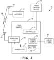
- FIG. 2is a simplified block diagram showing field device 14 shown in FIG. 1 in greater detail.
- Field device 14includes an optional transducer 31, wireless input/output (communication) circuitry 32, controller 34, power supply circuit 36, battery 38 and solar panel 40.
- the transducer 31can be either a sensor used to sense a process variable or a control element, such as a valve, which is used to control a process variable.
- the wireless communication circuitry 32couples to antenna 22 for communication with gateway 13 over its antenna 26.
- device 14communicates directly with control room 12.
- Power supply circuit 36is used to provide power to circuitry within field device 14.
- the power supply circuitry 36can operate using internal power received from solar cell 40 or power received from battery 38.
- the power supply circuitry 36can be powered from any type of internal power source that does not require wiring to a remote power source.
- the power supply circuitry 36can be self-contained within the field device 14 or, in some embodiments, be located externally to the field device and positioned proximate to the field device.
- a solar powered unitcan be used to power a transmitter or other field device over a two wire connection which is also used to carry information.
- the power supply circuitrycan also provide wireless communication to a remote location.
- Such configurationsare shown and described in U.S. patent application Serial No. 10/850,828 , WIRELESS POWER AND COMMUNICATION UNIT FOR PROCESS FIELD DEVICES filed on May 21. If sufficient power is received from solar cell 40, power supply circuitry 36 can also be used to charge the battery 38.
- An image capture device 74is used to capture images of an environment as explained below in more detail.
- FIG. 3is a more detailed block diagram of process device 14 according to an embodiment of the present invention and shows optional transducer 31 configured as a process variable sensor.
- the process variable sensor 31may be positioned within the housing of device 14 or external to the housing as illustrated in FIG. 3 .
- Measurement circuitry 52couples to process variable sensor 31 and is used to perform initial signal processing prior to providing a measurement signal to controller 34.
- An optional user input 54is shown as operator button in FIG. 3 .
- an optional output devicesuch as LCD display 56 is shown.
- Controller 34is typically a microprocessor based controller and couples to a memory 60 and a clock 62.
- the clock 62determines the operation speed of digital circuitry within field device 14 and memory 60 is used to store information.
- Memory 60can comprise both permanent and volatile memory and can be used to store data used during processing, programming instructions, calibration information, or other information, data or instructions for use with process device 14. Memory 60 also stores image information as described herein.
- FIG. 3also illustrates image capture device 74 in accordance with the present invention.
- Image capture device 74operates as discussed below in more detail and provides an image output consisting of image information to controller 34.
- a remote field deviceIn some instances it is desirable to visually monitor the environment surrounding a remote field device. Typically, such monitoring requires that a vehicle be dispatched with service personnel who must drive to a remote location to perform a visual inspection.
- the present inventionprovides for image monitoring of a remote environment 75 which may include process elements such as a flare, pump-jack, pump, tank, or other component proximate field device 14, 16 at a remote location. This can be used to provide information related to vehicles or personnel in the area, proper operation of equipment such as a pump or well, the presence of a fire or smoke, escaping process fluid, etc.
- Wireless field deviceswhich are capable of operating at remote locations that do not require an external power source are available from, for example, Rosemount Inc. of Chanhassen, MN. Such devices are configured to measure process variables or obtain other process information and transmit information using wireless communication techniques such as the WirelessHARTO protocol.
- wireless communication techniquessuch as the WirelessHARTO protocol.
- due to power and bandwidth limitations, such devicesare not well suited for transmitting large quantities of data such as is present in image data. Such transmission requires large power consumption and would rapidly deplete the battery of the device thereby shortening the amount of time the device could be left unattended in the field.
- the present inventionprovides a method and apparatus for providing image information from such a wireless field device.
- the image capture device 74comprises a CCD or a CMOS device.
- the image capture device 74optionally includes a lens to focus a desired region of the surrounding environment 75 onto the device 74.
- Optional processing circuitrycan be provided which is capable of detecting changes (deltas) in individual pixels or groups of pixels of the device.
- One example image capture device 74is an optical mouse sensor such as the ADNS-5090 by Avago Technologies or OV7995 by Omnivision Technologies. This is an example of a device which performs both image capture as well as detecting changes (deltas) in an image and is an implemented single integrated circuit.
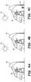
- FIGS. 4A, 4B and 4Care illustrations of an industrial process environment 75 and illustrate operation according to the present invention.
- a reference imageis shown of an oil rig 80.
- FIG. 4Bthe same reference image is shown and the sun 82 is also visible.
- FIG. 4Can individual 84 can be seen proximate the oil rig in addition to the sun 82.
- the reference image illustrated in FIG. 4Ais obtained by image capture device 74 and stored in memory 60.
- the reference imagemay be taken at a high resolution for enhanced image processing and analysis at a host site.
- the reference imagecan be transmitted at a slow data rate to a remote location such as control room 12 shown in FIG. 1 .
- the reference imageis transferred to the remote location using some means other than RF link 28, 30 and stored at the remote location as the reference image.
- some means other than RF link 28, 30can be used to move the image to the control room 12 shown in FIG. 1 .
- physical memorysuch as a memory stick can be used to move the image to the control room 12 shown in FIG. 1 .
- a second imageis captured by image capture device 74 such as illustrated in FIG. 4B .
- this imagediffers from the reference image of FIG. 4A in that the sun 82 is visible.
- subsequent imagesmay be taken minutes or even hours apart.
- the controller 34by identifying any changes (deltas) between the two images, the controller 34 only stores those portions (pixels) which have changed. In other words, the information from the image related to the sun 82 is stored in memory 60 and transmitted to a remote location using wireless communication through antenna 22. This conserves both memory and transmission bandwidth.
- FIG. 4CYet a second subsequent image is illustrated in FIG. 4C .
- an individual 84is visible proximate the oil rig.
- the imageis captured by the image capture device 74 and the controller 34 stores the changes (deltas) in memory 60 for subsequent wireless transmission.
- this delta informationis transmitted in near real time, or, according to an embodiment, may be stored in the memory 60 for subsequent transmission.
- the image informationmay be transmitted when data traffic on the wireless network 28, 30 is relatively low, or when additional power is available for transmission.
- the image information which is stored in memory 60 and/or transmitted over wireless communication link 28is compressed in some manner.
- the compressioncan use lossless or lossy techniques. In a lossless technique, no information is lost when the compression occurs. However, a lossy image compression technique results in the compressed image having less information than the original image.
- Example lossless image compression techniquesinclude run length encoding such as is available PCX, BMP, PNG, TGA and TIFF standards, predictive coding and differential pulse code modulation, entropy encoding, adaptive dictionary encoding algorithms (such as LZW which may be implemented in GIF and TIFF formats), deflation or chain codes.
- Lossy image compression techniquesinclude techniques which reduce the color space, chroma sub sampling, transform coding (such as implemented in the JPG standard) and fractal compression. However, the present invention is not limited to these compression techniques.
- the image compressioncan be implemented within the image capture device 74 itself, within controller 34, or performed by other circuitry in transmitter 14.
- controller 34operates in accordance with instructions stored in memory 60 which allow it to be "trained” to observe a known environment 75 and transmit event messages when certain events have occurred in the environment 75. For example, if a flare or a flame is detected in a particular region of the remote environment 75, a message can be transmitted wirelessly to that effect.
- imagesare captured by image capture device 74 at an increased frame rate during certain events to provide additional images detail of the remote environment 75. Additionally, the captured images may be of a higher resolution. Similarly, the controller 34 can receive instructions wirelessly which increase the rate at which images are captured and/or the resolution of captured images. This command may be generated by another device or may be sent by user.
- the controller 34when a change from the reference image is detected, the controller 34 only transmits information related to the location or region of the reference image in which the change occurred.
- this informationis received at the control system 12 shown in FIG. 2 , the reference image can be displayed to an operator along with information highlighting the region of the environment in which a change was detected. For example, if the highlighted region is at the location of a burner, this information can allow an operator to determine that a flame has been ignited or extinguished.
- the change in a captured image with respect to the reference imagecan be detected within the image capture device 74 itself, within controller 34, or by other circuitry within transmitter 14.
- FIG. 5is another example embodiment of wireless controller monitoring system 10.
- Control room 12is illustrated as including a PC 12A configured to run an image management application.
- a number of different WirelessHART ® devices 16are illustrated which communicate with control room 12 through gateway receiver 13. Communication between gateway 13 and control room 12 may be over a wired or wireless communication link.
- Field device 14is shown and includes a number of optional additional inputs. For example, a temperature sensor 90 and a current to capacitance interface 92 are shown.
- Optional GPS module 94may be implemented to provide location information to microcontroller 34 which can be used to identify environment 75 image.
- An optional USB interface 98is provided for interfacing with microcontroller 34.
- memory 60is illustrated as FRAM which is one example of a nonvolatile memory.
- the image information which is transmitted to remote locationmay optionally include additional information including real time information related to when the image was obtained, location information related to where the image was obtained, positioning information related to a direction that the image capture device is pointed, other sensor information such as temperature, process variables, etc., information which identifies the process device 14 which captured the image, or other information.
- the image capture device 74can be configured for use in harsh environments. For example, a nano coating be used to help ensure that the image aperture remains clean. Another example coating is titanium dioxide which prevents dirt and contaminants from adhering to glass.
- the image capture device 74can, itself, record information related to the condition of the aperture. For example, a baseline image may be obtained which is of a clean aperture. This can be used to detect when the aperture becomes dirty by comparing a current image with the baseline image and thereby alert an operator, for example, by transmitting information to control room 12.
- the memory 60 of the transmitter 14can store any number of images or delta information based upon its size and available power.
- Image informationcan be removed from the memory 60 once it has been transmitted.
- a signalis received by process device 14 which indicates that an image has been successfully received at a remote location thereby allowing the stored image to be erased from memory 60.
- the image informationcan be transmitted continuously, or can be transmitted in a number of different packets, such as through block transfers.
- Image change (delta) informationtypically requires less bandwidth.
- an image processing and management application running on PC 12Acan be configured to perform object recognition. For example, individuals, vehicles, flames, vapors or gas, smoke, pump position, etc., can be identified.
- the field device 14can obtain and/or transmit image information periodically, when a sufficient delta is detected in an image, or upon receipt of a command. Stored images as well as transmitted images may include time information. Further, the device can be configured to store any number of images based upon receipt of a command from a remote location. A host may request that the field device 14 obtain a series of images at a desired resolution and transmit those images.
- the image capture device 74includes an actuator to reposition the image capture device 74 to perform a pan and/or tilt function
- commandscan be sent to the device to control the positioning of the image capture device 74.
- the image capture device 74periodically changes position to observe different areas of the remote environment 75. If a focusing mechanism is provided with the capture device 74, this can further be utilized when capturing an image. In some configurations, the focusing mechanism can be used for near field image capture whereby contaminants on the lens or sensor may be detected.
- FIG. 6is a simplified diagram of one example configuration of image capture device 74.
- Image capture device 74includes an image sensor 120 such as a CCD or the like.
- the image sensor 120is arranged in a two-dimensional array to capture an image of remote environment 75 which is focused using lens 122.
- lens 122may include optional coatings to reduce debris accumulation.
- An output from sensor 120is provided to an image processor 124 which is related to the sensed image.
- Image processor 124is configured to process the individual pixels from sensor 120 and provide an output to microcontroller 34 discussed above. As also discussed above, in some configurations, processor 124 only provides an output related to changes in the sensed image.
- pan and tilt actuators 126 and 128, respectivelyare provided which can be controlled by microcontroller 34 such that image sensor 122 obtains images from different areas of the remote environment 75 as desired.
- the movementcan be in response to a command, occur periodically at a desired time interval, or in response to an event. For example, if a particular sensor in the process is giving an anomalous reading, the image capture device 74 can be pointed to observe that particular area of the process.
- the inventionincludes recording only changes in a capture image in order to reduce memory requirements and transmission bandwidth.
- captured image datais compressed using image compression techniques. This may include both lossy as well as lossless compression techniques. This also reduces storage and bandwidth requirements.
- image compression techniquesmay include both lossy as well as lossless compression techniques. This also reduces storage and bandwidth requirements.
- any stored image informationcan be removed from the memory 60. If the storage limit of the memory is reached, older images can be deleted in a first in, first out basis. Large amounts of image data, for example, reference images, can be transferred using multiple blocks or packets sent over the wireless communication link. Smaller amounts of image data, for example image delta information, can be transferred using fewer packets. In one configuration, only information related to a region of the image in which a change occurred is transmitted.
- a PC 12Acan operate an image management application and use to combine a baseline reference image with image delta information. This can be used to reconstruct an image for an operator based upon the baseline reference image and the image delta information.
- the image management applicationcan further be configured to perform object recognition to recognize various objects or actions in the remote environment 75. Such objects or actions include recognizing people, vehicles, flames, vapor/gas, etc.
- the applicationcan be configured to recognize events such as a flare, people or vehicles entering an area, a flame or explosion, fluid discharge, etc.
- the applicationcan be configured to display a plurality of images on a display to provide an animation viewable by an operator. For example, an operator can configure a selected number of images to be displayed in sequence with a selected starting and ending times.
- image display techniquescan be employed, such as, providing exaggeration to those regions of an image containing motion. Object or action recognition can then be performed on the process video for increased detection sensitivity. This allows the image management application to mathematically exaggerate image change (delta) information to make subtle changes more apparent.
- image changeimage change
- One example techniquehas been developed by the Massachusetts Institute of Technology (MIT) and is described in, " MIT News, researchers amplify variations in video, making the invisible visible, Larry Hardesty, June 22, 2012, http://web.mit.edu/newsoffice/2012/amplifying-invisible0video-0622/html ).
- the images transferred over the wireless communication link 28can include additional information such as a time stamp, geographical information, information regarding sensed process variables, information which identifies the portion of the remote environment 75 which is being monitored, information related to a direction at which the image capture device is pointed, etc.
- the compressed image informationis transmitted over the wireless network as packets of information.
- the wireless networkis typically part of a larger network including multiple wireless devices.
- other process related informationsuch as process variables are also transmitted on the same network. It is important that process variables be able to be transmitted.
- the network bandwidthmay be limited thereby reducing the amount of bandwidth available for process variable transmission.
- the bandwidth required to transmit imagesis reduced by sending compressed image data.
- the data packets which contain image informationcan be tagged with priority information that indicates that they have a lower transmission priority than other packets of information on the wireless network such as packets containing information related to process variables.
- the controller 34has sufficient processing power such that image processing may be performed within the field device 14.
- the devicecan monitor the local environment 75 and transmit event messages when certain events have been observed, such as the presence or absence of a flame, etc.
- an image of the eventis stored in the memory 60.
- An occurrence of the eventcan be detected by comparing the stored event image with current image data from the image capture device 74.
- the field device 14can transmit event status information periodically, or only upon the occurrence and detection of an event.
- the field devicemay transmit only the event status information but may also include image information including image delta information. Any image information obtained during an event can be stored in the memory 60 including time stamp information.
- the image management application 12Aupon receipt of an event status, can control the field device 14 to cause it to collect a series of images for subsequent transmission. The image management application 12A can verify the event prior to an operator being notified.
- compressed image informationrefers to image information which has been compressed in a manner to consist of less data than original image information.
- the compressioncan be lossless or lossy and includes techniques which simply provide information related to a location in an image in which the image has changed including how much the image has changed in that particular location. It does not include information which simply indicates that something in an image has changed without any information regarding a location.
- image change informationincludes information which indicates that there has been a change in at least some portion of the image, and includes such information which does not have to specifically indicate where in an image a change has occurred.
- Transmission of compressed image information or image change informationcan be triggered by comparing an amount of change to a threshold. If a threshold is exceeded, transmission can be enabled.
- the image capture devicecan be sensitive to any desired wavelength including optical, infrared and ultraviolet. In one aspect, the field device operates using power stored in an internal battery or the like.
Landscapes
- Engineering & Computer Science (AREA)
- Multimedia (AREA)
- Signal Processing (AREA)
- Physics & Mathematics (AREA)
- General Physics & Mathematics (AREA)
- Automation & Control Theory (AREA)
- General Engineering & Computer Science (AREA)
- Manufacturing & Machinery (AREA)
- Quality & Reliability (AREA)
- Closed-Circuit Television Systems (AREA)
- Selective Calling Equipment (AREA)
- Arrangements For Transmission Of Measured Signals (AREA)
Description
- The present invention relates to an industrial process control or monitoring system and an industrial process control or monitoring method for such a system. More specifically, the present invention relates to a communication between wireless process field devices and a controller used in such systems.
- In industrial settings, systems are used to monitor and control inventories and operation of industrial and chemical processes, and the like. Typically, the system that performs these functions uses field devices distributed at key locations in the industrial process coupled to control circuitry in the control room by a process control loop. The term "field device" refers to any device that performs a function in a distributed control or process monitoring system, including all devices used in the measurement, control and monitoring of industrial processes.
- Typically, each field device also includes communication circuitry that is used for communicating with a process controller, other field devices, or other circuitry, over the process control loop. In some installations, the process control loop is also used to deliver a regulated current and/or voltage to the field device for powering the field device. The process control loop also carries data, either in an analog or digital format.
- In some installations, wireless technologies have begun to be used to communicate with field devices. Wireless operation simplifies field device wiring and setup. Wireless installations are currently used in which the field device includes a local power source. However, because of power limitations, the functionality of such devices is typically limited. Further, in some instances, field devices are located at remote locations where it is difficult to visually monitor the surrounding environment. Often, a vehicle must be dispatched with service personnel in order to inspect the site. This may be many miles away and require significant travel time to visit a particularly remote location.
U.S. 2007/019077 discloses a portable surveillance camera and a personal surveillance system are disclosed. More specifically, provided are a portable surveillance camera comprising a mini-camera such as a CMOS camera or a CCD camera, and a system for surveilling a predetermined place using the portable surveillance camera. The personal surveillance system receives multimedia data such as image, sound, event and control data on real time from the portable surveillance camera installed in various areas such as a house, a shop or an office with a control device connectable to a network such as a LAN or an internet, and then monitors or stores the multimedia data. Also, the personal surveillance system can search, surveille, control, edit and store multimedia data such as image, sound, event and control data for a desired period of time from data stored in the portable surveillance camera or the control device.US 2007/052804 discloses a mobile video surveillance system is provided having portable video units communicating in a wireless network. The individual portable video units have a wireless router coupled to a video camera that is held by a portable mounting device. The wireless routers coupled to the video cameras, at the deployed portable video units, transmit video data via the wireless network to a wireless router that is coupled with a video server. The video server receives video data from the portable video units for display at the video server.US 2006/0148410 relates to industrial process control or monitoring systems and wireless process field devices used in a monitoring system, comprising a controller configured to control operation of the field device in an industrial process; wireless communication circuitry configured to wirelessly communicate with a remote location; an internal power source configured to wholly power the field device; and an image capture device coupled to the controller configured to capture an image of an environment of the field device.WO 2013/006 307 A1 relates to a wireless field device with removable power source which includes wireless communication circuitry to provide wireless communication.- The object of the present invention is to provide an industrial process control or monitoring system and a corresponding method which can use a small communication bandwidth and little power when a controller which controls an operation of a field device communicates wirelessly with a remote location. This object is solved by the attached independent claims and further advantageous embodiments and improvements of the present invention are listed in the dependent claims.
FIG. 1 is a simplified block diagram showing a process control or monitoring system for use with the present invention.FIG. 2 is a block diagram showing components in a field device of one embodiment of the present invention.FIG. 3 is a more detailed block diagram showing components of the field device ofFIG. 2 .FIGS. 4A, 4B, and 4C show example remote environments which may be subject to image capture by the present invention.FIG. 5 is another example block diagram similar toFIG. 1 of a process controller monitoring system.FIG. 6 is a simplified diagram of an image capture device according to an embodiment of the invention.FIG. 1 is a simplified diagram showing an example process control ormonitoring system 10 which includes acontrol room 12 communicating withfield devices wireless gateway 13. Communication betweengateway 13 andcontrol room 12 may be over a wired or wireless communication link.Field device 14 is shown coupled to processpiping 18 andfield device 16 is shown coupled tostorage tank 20. However,devices Devices antennas antenna 26 associated withwireless gateway 13.Devices communication links gateway 13. One example wireless communication protocol is the WirelessHARTO protocol in accordance with IEC 62591.Field devices device - As
field device wireless field devices field device FIG. 2 is a simplified block diagram showingfield device 14 shown inFIG. 1 in greater detail.Field device 14 includes anoptional transducer 31, wireless input/output (communication)circuitry 32,controller 34,power supply circuit 36,battery 38 andsolar panel 40. Thetransducer 31 can be either a sensor used to sense a process variable or a control element, such as a valve, which is used to control a process variable. Thewireless communication circuitry 32 couples toantenna 22 for communication withgateway 13 over itsantenna 26. Optionally,device 14 communicates directly withcontrol room 12.Power supply circuit 36 is used to provide power to circuitry withinfield device 14. Thepower supply circuitry 36 can operate using internal power received fromsolar cell 40 or power received frombattery 38. Thepower supply circuitry 36 can be powered from any type of internal power source that does not require wiring to a remote power source. Thepower supply circuitry 36 can be self-contained within thefield device 14 or, in some embodiments, be located externally to the field device and positioned proximate to the field device. For example, a solar powered unit can be used to power a transmitter or other field device over a two wire connection which is also used to carry information. In such a configuration, the power supply circuitry can also provide wireless communication to a remote location. Such configurations are shown and described inU.S. patent application Serial No. 10/850,828 , WIRELESS POWER AND COMMUNICATION UNIT FOR PROCESS FIELD DEVICES filed on May 21. If sufficient power is received fromsolar cell 40,power supply circuitry 36 can also be used to charge thebattery 38. Animage capture device 74 is used to capture images of an environment as explained below in more detail.FIG. 3 is a more detailed block diagram ofprocess device 14 according to an embodiment of the present invention and showsoptional transducer 31 configured as a process variable sensor. Theprocess variable sensor 31 may be positioned within the housing ofdevice 14 or external to the housing as illustrated inFIG. 3 .Measurement circuitry 52 couples to processvariable sensor 31 and is used to perform initial signal processing prior to providing a measurement signal tocontroller 34. Anoptional user input 54 is shown as operator button inFIG. 3 . Similarly, an optional output device such asLCD display 56 is shown.Controller 34 is typically a microprocessor based controller and couples to amemory 60 and aclock 62. Theclock 62 determines the operation speed of digital circuitry withinfield device 14 andmemory 60 is used to store information.Memory 60 can comprise both permanent and volatile memory and can be used to store data used during processing, programming instructions, calibration information, or other information, data or instructions for use withprocess device 14.Memory 60 also stores image information as described herein.FIG. 3 also illustratesimage capture device 74 in accordance with the present invention.Image capture device 74 operates as discussed below in more detail and provides an image output consisting of image information tocontroller 34.- As discussed in the Background section, in some instances it is desirable to visually monitor the environment surrounding a remote field device. Typically, such monitoring requires that a vehicle be dispatched with service personnel who must drive to a remote location to perform a visual inspection. The present invention provides for image monitoring of a
remote environment 75 which may include process elements such as a flare, pump-jack, pump, tank, or other componentproximate field device - Wireless field devices which are capable of operating at remote locations that do not require an external power source are available from, for example, Rosemount Inc. of Chanhassen, MN. Such devices are configured to measure process variables or obtain other process information and transmit information using wireless communication techniques such as the WirelessHARTO protocol. However, due to power and bandwidth limitations, such devices are not well suited for transmitting large quantities of data such as is present in image data. Such transmission requires large power consumption and would rapidly deplete the battery of the device thereby shortening the amount of time the device could be left unattended in the field. The present invention provides a method and apparatus for providing image information from such a wireless field device.
- In one example configuration, the
image capture device 74 comprises a CCD or a CMOS device. Theimage capture device 74 optionally includes a lens to focus a desired region of the surroundingenvironment 75 onto thedevice 74. Optional processing circuitry can be provided which is capable of detecting changes (deltas) in individual pixels or groups of pixels of the device. One exampleimage capture device 74 is an optical mouse sensor such as the ADNS-5090 by Avago Technologies or OV7995 by Omnivision Technologies. This is an example of a device which performs both image capture as well as detecting changes (deltas) in an image and is an implemented single integrated circuit. FIGS. 4A, 4B and 4C are illustrations of anindustrial process environment 75 and illustrate operation according to the present invention. InFIG. 4A , a reference image is shown of anoil rig 80. InFIG. 4B , the same reference image is shown and thesun 82 is also visible. InFIG. 4C , an individual 84 can be seen proximate the oil rig in addition to thesun 82. According to the invention, the reference image illustrated inFIG. 4A is obtained byimage capture device 74 and stored inmemory 60. The reference image may be taken at a high resolution for enhanced image processing and analysis at a host site. The reference image can be transmitted at a slow data rate to a remote location such ascontrol room 12 shown inFIG. 1 . In another not claimed example which does not belong to the invention, the reference image is transferred to the remote location using some means other thanRF link control room 12 shown inFIG. 1 . According to the invention, at a subsequent time, a second image is captured byimage capture device 74 such as illustrated inFIG. 4B . In 4B, this image differs from the reference image ofFIG. 4A in that thesun 82 is visible. For example, subsequent images may be taken minutes or even hours apart. According to the invention, by identifying any changes (deltas) between the two images, thecontroller 34 only stores those portions (pixels) which have changed. In other words, the information from the image related to thesun 82 is stored inmemory 60 and transmitted to a remote location using wireless communication throughantenna 22. This conserves both memory and transmission bandwidth.- Yet a second subsequent image is illustrated in
FIG. 4C . In this figure, an individual 84 is visible proximate the oil rig. Again, according to the invention, the image is captured by theimage capture device 74 and thecontroller 34 stores the changes (deltas) inmemory 60 for subsequent wireless transmission. According to the invention, this delta information is transmitted in near real time, or, according to an embodiment, may be stored in thememory 60 for subsequent transmission. For example, the image information may be transmitted when data traffic on thewireless network - The image information which is stored in
memory 60 and/or transmitted overwireless communication link 28 is compressed in some manner. The compression can use lossless or lossy techniques. In a lossless technique, no information is lost when the compression occurs. However, a lossy image compression technique results in the compressed image having less information than the original image. Example lossless image compression techniques include run length encoding such as is available PCX, BMP, PNG, TGA and TIFF standards, predictive coding and differential pulse code modulation, entropy encoding, adaptive dictionary encoding algorithms (such as LZW which may be implemented in GIF and TIFF formats), deflation or chain codes. Lossy image compression techniques include techniques which reduce the color space, chroma sub sampling, transform coding (such as implemented in the JPG standard) and fractal compression. However, the present invention is not limited to these compression techniques. The image compression can be implemented within theimage capture device 74 itself, withincontroller 34, or performed by other circuitry intransmitter 14. - In one configuration,
controller 34 operates in accordance with instructions stored inmemory 60 which allow it to be "trained" to observe a knownenvironment 75 and transmit event messages when certain events have occurred in theenvironment 75. For example, if a flare or a flame is detected in a particular region of theremote environment 75, a message can be transmitted wirelessly to that effect. - In some configurations, images are captured by
image capture device 74 at an increased frame rate during certain events to provide additional images detail of theremote environment 75. Additionally, the captured images may be of a higher resolution. Similarly, thecontroller 34 can receive instructions wirelessly which increase the rate at which images are captured and/or the resolution of captured images. This command may be generated by another device or may be sent by user. - In another example image compression technique, when a change from the reference image is detected, the
controller 34 only transmits information related to the location or region of the reference image in which the change occurred. When this information is received at thecontrol system 12 shown inFIG. 2 , the reference image can be displayed to an operator along with information highlighting the region of the environment in which a change was detected. For example, if the highlighted region is at the location of a burner, this information can allow an operator to determine that a flame has been ignited or extinguished. The change in a captured image with respect to the reference image can be detected within theimage capture device 74 itself, withincontroller 34, or by other circuitry withintransmitter 14. FIG. 5 is another example embodiment of wirelesscontroller monitoring system 10.Control room 12 is illustrated as including aPC 12A configured to run an image management application. A number of different WirelessHART® devices 16 are illustrated which communicate withcontrol room 12 throughgateway receiver 13. Communication betweengateway 13 andcontrol room 12 may be over a wired or wireless communication link.Field device 14 is shown and includes a number of optional additional inputs. For example, atemperature sensor 90 and a current to capacitanceinterface 92 are shown.Optional GPS module 94 may be implemented to provide location information tomicrocontroller 34 which can be used to identifyenvironment 75 image. An optional USB interface 98 is provided for interfacing withmicrocontroller 34. InFIG. 5 ,memory 60 is illustrated as FRAM which is one example of a nonvolatile memory.- The image information which is transmitted to remote location may optionally include additional information including real time information related to when the image was obtained, location information related to where the image was obtained, positioning information related to a direction that the image capture device is pointed, other sensor information such as temperature, process variables, etc., information which identifies the
process device 14 which captured the image, or other information. - The
image capture device 74 can be configured for use in harsh environments. For example, a nano coating be used to help ensure that the image aperture remains clean. Another example coating is titanium dioxide which prevents dirt and contaminants from adhering to glass. Theimage capture device 74 can, itself, record information related to the condition of the aperture. For example, a baseline image may be obtained which is of a clean aperture. This can be used to detect when the aperture becomes dirty by comparing a current image with the baseline image and thereby alert an operator, for example, by transmitting information to controlroom 12. - The
memory 60 of thetransmitter 14 can store any number of images or delta information based upon its size and available power. Image information can be removed from thememory 60 once it has been transmitted. In one configuration, a signal is received byprocess device 14 which indicates that an image has been successfully received at a remote location thereby allowing the stored image to be erased frommemory 60. The image information can be transmitted continuously, or can be transmitted in a number of different packets, such as through block transfers. Image change (delta) information typically requires less bandwidth. - In one configuration, an image processing and management application running on
PC 12A can be configured to perform object recognition. For example, individuals, vehicles, flames, vapors or gas, smoke, pump position, etc., can be identified. Thefield device 14 can obtain and/or transmit image information periodically, when a sufficient delta is detected in an image, or upon receipt of a command. Stored images as well as transmitted images may include time information. Further, the device can be configured to store any number of images based upon receipt of a command from a remote location. A host may request that thefield device 14 obtain a series of images at a desired resolution and transmit those images. Similarly, if theimage capture device 74 includes an actuator to reposition theimage capture device 74 to perform a pan and/or tilt function, commands can be sent to the device to control the positioning of theimage capture device 74. In a related configuration, theimage capture device 74 periodically changes position to observe different areas of theremote environment 75. If a focusing mechanism is provided with thecapture device 74, this can further be utilized when capturing an image. In some configurations, the focusing mechanism can be used for near field image capture whereby contaminants on the lens or sensor may be detected. FIG. 6 is a simplified diagram of one example configuration ofimage capture device 74.Image capture device 74 includes animage sensor 120 such as a CCD or the like. Theimage sensor 120 is arranged in a two-dimensional array to capture an image ofremote environment 75 which is focused usinglens 122. As discussed above,lens 122 may include optional coatings to reduce debris accumulation. An output fromsensor 120 is provided to animage processor 124 which is related to the sensed image.Image processor 124 is configured to process the individual pixels fromsensor 120 and provide an output tomicrocontroller 34 discussed above. As also discussed above, in some configurations,processor 124 only provides an output related to changes in the sensed image. In another optional configuration, pan andtilt actuators microcontroller 34 such thatimage sensor 122 obtains images from different areas of theremote environment 75 as desired. The movement can be in response to a command, occur periodically at a desired time interval, or in response to an event. For example, if a particular sensor in the process is giving an anomalous reading, theimage capture device 74 can be pointed to observe that particular area of the process.- According to the invention, the invention includes recording only changes in a capture image in order to reduce memory requirements and transmission bandwidth. Also in accordance with the invention, captured image data is compressed using image compression techniques. This may include both lossy as well as lossless compression techniques. This also reduces storage and bandwidth requirements. Further, once the image data has been transmitted from the
field device 14, any stored image information can be removed from thememory 60. If the storage limit of the memory is reached, older images can be deleted in a first in, first out basis. Large amounts of image data, for example, reference images, can be transferred using multiple blocks or packets sent over the wireless communication link. Smaller amounts of image data, for example image delta information, can be transferred using fewer packets. In one configuration, only information related to a region of the image in which a change occurred is transmitted. - A
PC 12A can operate an image management application and use to combine a baseline reference image with image delta information. This can be used to reconstruct an image for an operator based upon the baseline reference image and the image delta information. The image management application can further be configured to perform object recognition to recognize various objects or actions in theremote environment 75. Such objects or actions include recognizing people, vehicles, flames, vapor/gas, etc. Similarly, the application can be configured to recognize events such as a flare, people or vehicles entering an area, a flame or explosion, fluid discharge, etc. In another example embodiment, the application can be configured to display a plurality of images on a display to provide an animation viewable by an operator. For example, an operator can configure a selected number of images to be displayed in sequence with a selected starting and ending times. Other image display techniques can be employed, such as, providing exaggeration to those regions of an image containing motion. Object or action recognition can then be performed on the process video for increased detection sensitivity. This allows the image management application to mathematically exaggerate image change (delta) information to make subtle changes more apparent. One example technique has been developed by the Massachusetts Institute of Technology (MIT) and is described in, "MIT News, Researchers amplify variations in video, making the invisible visible, Larry Hardesty, June 22, 2012, http://web.mit.edu/newsoffice/2012/amplifying-invisible0video-0622/html). - The images transferred over the
wireless communication link 28 can include additional information such as a time stamp, geographical information, information regarding sensed process variables, information which identifies the portion of theremote environment 75 which is being monitored, information related to a direction at which the image capture device is pointed, etc. The compressed image information is transmitted over the wireless network as packets of information. Note that the wireless network is typically part of a larger network including multiple wireless devices. In many instances, other process related information such as process variables are also transmitted on the same network. It is important that process variables be able to be transmitted. However, if large amounts of image data are being transmitted on the network, the network bandwidth may be limited thereby reducing the amount of bandwidth available for process variable transmission. Thus, the bandwidth required to transmit images is reduced by sending compressed image data. Further, the data packets which contain image information can be tagged with priority information that indicates that they have a lower transmission priority than other packets of information on the wireless network such as packets containing information related to process variables. - In some configurations, the
controller 34 has sufficient processing power such that image processing may be performed within thefield device 14. For example, the device can monitor thelocal environment 75 and transmit event messages when certain events have been observed, such as the presence or absence of a flame, etc. In one example configuration, an image of the event is stored in thememory 60. An occurrence of the event can be detected by comparing the stored event image with current image data from theimage capture device 74. Thefield device 14 can transmit event status information periodically, or only upon the occurrence and detection of an event. As desired, the field device may transmit only the event status information but may also include image information including image delta information. Any image information obtained during an event can be stored in thememory 60 including time stamp information. In another example configuration, upon receipt of an event status, theimage management application 12A can control thefield device 14 to cause it to collect a series of images for subsequent transmission. Theimage management application 12A can verify the event prior to an operator being notified. - Although the present invention has been described with reference to preferred embodiments, workers skilled in the art will recognize that changes may be made in form and detail without departing from the scope of the invention, which is defined in the appended claims. As used herein, the term "compressed image information" refers to image information which has been compressed in a manner to consist of less data than original image information. The compression can be lossless or lossy and includes techniques which simply provide information related to a location in an image in which the image has changed including how much the image has changed in that particular location. It does not include information which simply indicates that something in an image has changed without any information regarding a location. Further, the term "image change information" includes information which indicates that there has been a change in at least some portion of the image, and includes such information which does not have to specifically indicate where in an image a change has occurred. Transmission of compressed image information or image change information can be triggered by comparing an amount of change to a threshold. If a threshold is exceeded, transmission can be enabled. The image capture device can be sensitive to any desired wavelength including optical, infrared and ultraviolet. In one aspect, the field device operates using power stored in an internal battery or the like.
Claims (14)
- An industrial process control or monitoring system (10) including a control room (12) at a remote location and one or more field devices (14, 16) communicating with the control room (12), the field device (14, 16) comprising:a0) a controller (34) configured to control operation of the field device (14) in an industrial process;a) wireless communication circuitry (32) configured to wirelessly communicate with the control room (12) at the remote location using a communication protocol which has bandwidth limitations;b) an internal power source (36) configured to wholly power the field device (14); andc) an image capture device (74) coupled to the controller (34) configured to capture an image of an environment of the field device (14), including process elements proximate to the field device (14), which are captured within the image as image information;c1) a memory (60) configured to store image information from images captured by the image capture device (74);c2) wherein the controller (34) is adapted toretrieve image information from the memory,detect a difference between an image captured by the image capture device (74) and the stored image information,d) wherein the controller (34) is further adapted to compress the image information and transmit compressed image information to the remote location based upon the detected difference between the image captured by the image capture device (74) and the stored image information, thereby reducing communication bandwidth used to transmit image information to the remote location and reduce power consumed by the wireless field device from the internal power source;e1) wherein the image capture device (74) is adapted to capture a first image of the environment of the field device (14, 16) at a first time, the memory (60) is adapted to store the first image as a reference image, and wherein the reference image is also stored at the control room (12) at the remote location;e2) wherein the image capture device (74) is further adapted to capture a second image of the environment of the field device (14, 16) at a subsequent second time,e3) wherein the controller (34) is adapted to, for detecting a difference between the second image captured by the image capture device (74) and the stored reference image, identify changes between the two images and only store as delta image information those portions which have changed, ande4) wherein the controller (34) is adapted to transmit to the remote location (16), as said compressed image information, the delta image information after compressing same.
- The system of claim 1, wherein the stored image information comprises baseline image information, compressed image information, or image change information.
- The system of claim 1 or 2, wherein the compressed image information includes:higher resolution image information in response to a command received through the wireless communication circuitry,higher resolution image information in response to detection of a change in the image,higher frame rate image information in response to a command received through the wireless communication circuitry,higher frame rate image information in response to detection of a change in the image,lossy compressed image information,lossless compressed image information, orlocation information related to a location in the image at which the image has changed.
- The system (14) of one of the claims 1 to 3, including an actuator configured to reposition the image capture device (74).
- The system of one of the claims 1 to 4, further including a process variable sensor (31) and wherein information related to a sensed process variable is communicated by the wireless communication circuitry (32).
- The system of one of the claims 1 to 5, including an image management application configured to display a plurality of captured images in an animation.
- The system of one of the claims 1 to 6, including an image management application configured to exaggerate image change information to thereby amplify changes in the captured images.
- The system of claim 1, including an image management application at the remote location configured to receive the compressed image information.
- The system of claim 8, wherein the image management application includes a baseline image.
- The system of claim 8 or 9, wherein the image management application is configured to identify objects in the image.
- The system of claim 1 including the wireless field device of claim 1 and a second wireless field device, the second wireless field device configured to wirelessly transmit process variable information on a same wireless network as the wireless field device.
- The system of claim 11, wherein the compressed image information is transmitted with a reduced priority level.
- An industrial process control or monitoring method for an industrial process control or monitoring system (10) including a control room (12) at a remote location and one or more field devices (14, 16) communicating with the control room (12), the method comprising:a) receiving from an image capture device (74) of the field device (14, 16), an image of an environment of the wireless field device (14), including process elements proximate to the field device (14), which are captured within the image as image information;b) storing image information from the captured image into a memory;c1) processing the stored image information with a controller (34) in the wireless field device (14), detecting a difference between an image captured by the image capture device and the stored image information, and generating compressed image information;c2) wholly powering the field device (14) with an internal power source (26) which is internal to the field device (14); andd) wirelessly communicating the compressed image information to a remote location using wireless communication circuitry (32) in the wireless field device (14) based upon the detected difference between the image captured by the image capture device and the stored image information, thereby reducing communication bandwidth used to transmit image information to the remote location and reduce power consumed by the wireless field device from the internal power source;e1) wherein step a) includes that the image capture device (74) captures a first image of the environment of the field device (14, 16) at a first time, step b) includes that the memory (60) stores the first image as a reference image, and the reference image is also stored at the control room (12) at the remote location;e2) wherein step a) further includes that the image capture device (74) captures a second image of the environment of the field device (14, 16) at a subsequent second time,e3) step c1) includes, for detecting a difference between the second image captured by the image capture device (74) and the stored reference image, identifying changes between the two images and only storing as delta image information those portions which have changed, ande4) step c) comprises transmitting to the remote location (16), as said compressed image information, the delta image information after compressing same.
- The method of claim 13 including storing the compressed image information in a memory.
Applications Claiming Priority (2)
| Application Number | Priority Date | Filing Date | Title |
|---|---|---|---|
| US14/038,090US10638093B2 (en) | 2013-09-26 | 2013-09-26 | Wireless industrial process field device with imaging |
| PCT/US2014/051625WO2015047596A1 (en) | 2013-09-26 | 2014-08-19 | Wireless industrial process field device with imaging |
Publications (2)
| Publication Number | Publication Date |
|---|---|
| EP3050293A1 EP3050293A1 (en) | 2016-08-03 |
| EP3050293B1true EP3050293B1 (en) | 2023-05-03 |
Family
ID=51493047
Family Applications (1)
| Application Number | Title | Priority Date | Filing Date |
|---|---|---|---|
| EP14761467.1AActiveEP3050293B1 (en) | 2013-09-26 | 2014-08-19 | Wireless industrial process field device with imaging |
Country Status (9)
| Country | Link |
|---|---|
| US (1) | US10638093B2 (en) |
| EP (1) | EP3050293B1 (en) |
| JP (1) | JP2016540397A (en) |
| CN (2) | CN115826535A (en) |
| AU (2) | AU2014328666A1 (en) |
| BR (1) | BR112016006476A2 (en) |
| CA (1) | CA2923156C (en) |
| RU (1) | RU2631256C1 (en) |
| WO (1) | WO2015047596A1 (en) |
Families Citing this family (8)
| Publication number | Priority date | Publication date | Assignee | Title |
|---|---|---|---|---|
| US10638093B2 (en)* | 2013-09-26 | 2020-04-28 | Rosemount Inc. | Wireless industrial process field device with imaging |
| US20160036906A1 (en)* | 2014-08-04 | 2016-02-04 | Vixlet LLC | Dynamic adjustment of client thickness |
| US11086025B2 (en)* | 2015-08-13 | 2021-08-10 | Propeller Aerobotics Pty Ltd | Integrated visual geo-referencing target unit and method of operation |
| WO2020086071A1 (en)* | 2018-10-24 | 2020-04-30 | Siemens Energy, Inc. | System and method to automatically optically monitoring field devices and assess state information |
| EP3683743A1 (en)* | 2019-01-17 | 2020-07-22 | Basf Se | Computer-implemented method, system and computer program for providing audit records that relate to technical equipment |
| CN110246157B (en)* | 2019-06-21 | 2020-09-04 | 大庆安瑞达科技开发有限公司 | Oil-gas field equipment production state distinguishing system and method based on big data monitoring |
| CN113341802A (en)* | 2021-06-01 | 2021-09-03 | 江西凯天电力科技发展有限公司 | Intelligent and safe electricity utilization operation and maintenance management system and method |
| JP7713920B2 (en)* | 2022-09-20 | 2025-07-28 | 株式会社Kokusai Electric | Substrate processing apparatus, semiconductor device manufacturing method, and program |
Citations (2)
| Publication number | Priority date | Publication date | Assignee | Title |
|---|---|---|---|---|
| US20040156549A1 (en)* | 1998-10-01 | 2004-08-12 | Cirrus Logic, Inc. | Feedback scheme for video compression system |
| US20060148410A1 (en)* | 2005-01-03 | 2006-07-06 | Nelson Richard L | Wireless process field device diagnostics |
Family Cites Families (134)
| Publication number | Priority date | Publication date | Assignee | Title |
|---|---|---|---|---|
| US3857277A (en) | 1972-12-29 | 1974-12-31 | Laval Turbine | Flow indicator |
| JPS52140779A (en) | 1976-05-19 | 1977-11-24 | Daikin Ind Ltd | Methods of discriminating quality of the equipment in hydraulic device |
| JPS5386111A (en) | 1977-01-07 | 1978-07-29 | Toshiba Corp | Monitor device |
| JPS5567618A (en) | 1978-11-17 | 1980-05-21 | Toukiyouto | Liquid meter of electronic integrating type |
| JPS5890882A (en) | 1981-11-24 | 1983-05-30 | Mitsubishi Electric Corp | Elevator monitoring device |
| JPS61136340A (en) | 1984-12-06 | 1986-06-24 | Kubota Ltd | Oil well control method |
| JPS62179647A (en) | 1986-02-03 | 1987-08-06 | Mitsubishi Heavy Ind Ltd | Inner wall defect inspector for high temperature container |
| US4736250A (en) | 1986-11-28 | 1988-04-05 | Tektronix, Inc. | Digital camera frame capture circuit |
| DE3642182A1 (en) | 1986-12-10 | 1988-06-23 | Wolf & Co Kg Kurt | ARRANGEMENT FOR MEASURING THE TEMPERATURE IN A HEATING SYSTEM OF COOKING PLATE AND COOKER WITH COOKING MATERIAL |
| JPS6473880A (en) | 1987-09-14 | 1989-03-20 | Matsushita Electric Works Ltd | Iamge transmission system |
| US4947247A (en) | 1989-06-20 | 1990-08-07 | Combustion Engineering, Inc. | Displacement measurement apparatus and method for an automated flow rotameter |
| US5056046A (en) | 1989-06-20 | 1991-10-08 | Combustion Engineering, Inc. | Pneumatic operated valve data acquisitioner |
| US5109277A (en) | 1990-06-20 | 1992-04-28 | Quadtek, Inc. | System for generating temperature images with corresponding absolute temperature values |
| US5144430A (en) | 1991-08-09 | 1992-09-01 | North American Philips Corporation | Device and method for generating a video signal oscilloscope trigger signal |
| US5292195A (en) | 1992-09-09 | 1994-03-08 | Martin Marietta Corporation | Thermographic evaluation technique |
| JPH07318576A (en) | 1994-05-11 | 1995-12-08 | Xerox Corp | Fluid sensing device |
| JPH07325900A (en) | 1994-05-31 | 1995-12-12 | Dainippon Printing Co Ltd | Cards and how to use them |
| US5654977A (en) | 1995-02-02 | 1997-08-05 | Teledyne Industries Inc. | Method and apparatus for real time defect inspection of metal at elevated temperature |
| JP3401136B2 (en) | 1996-03-28 | 2003-04-28 | 三菱電機株式会社 | Plant equipment inspection system |
| JPH1047312A (en) | 1996-07-31 | 1998-02-17 | Nkk Corp | How to detect internal leakage of hydraulic cylinder |
| US6000844A (en) | 1997-03-04 | 1999-12-14 | The United States Of America As Represented By The Administrator Of The National Aeronautics And Space Administration | Method and apparatus for the portable identification of material thickness and defects using spatially controlled heat application |
| US6259810B1 (en) | 1997-04-15 | 2001-07-10 | Microsoft Corporation | Method and system of decoding compressed image data |
| JPH10294933A (en) | 1997-04-18 | 1998-11-04 | Mitsubishi Electric Corp | Video surveillance system |
| US6346704B2 (en) | 1997-06-06 | 2002-02-12 | Osb Scan Inc. | Defect detection in articles using computer modelled dissipation correction differential time delayed far IR scanning |
| JP3361726B2 (en) | 1997-06-30 | 2003-01-07 | 株式会社日立製作所 | Liquid level measuring method and device |
| JPH1175176A (en) | 1997-07-02 | 1999-03-16 | Matsushita Electric Ind Co Ltd | Remote monitoring system and remote monitoring method |
| TW474949B (en) | 1997-10-03 | 2002-02-01 | Mitsui Chemicals Inc | A fluidized bed polymerization apparatus and an olefin polymerization process |
| JPH11189603A (en) | 1997-10-03 | 1999-07-13 | Mitsui Chem Inc | Fluidized-bed type polymerization apparatus and polymerization of olefin |
| JP3605285B2 (en) | 1997-11-25 | 2004-12-22 | 三菱電機株式会社 | Thermal infrared detector array |
| US6059453A (en) | 1998-04-20 | 2000-05-09 | Rosemount Inc. | Temperature probe with sapphire thermowell |
| FR2779728B1 (en) | 1998-06-10 | 2001-04-13 | Inst Francais Du Petrole | GRAFT SEQUENCE POLYMERS CONTAINING AT LEAST ONE POLYOLEFINIC OR POLYDIENIC SEQUENCE COMPRISING A SUCCINIMIDE CYCLE SUBSTITUTED ON NITROGEN BY A REACTIVE GROUP |
| US7640007B2 (en) | 1999-02-12 | 2009-12-29 | Fisher-Rosemount Systems, Inc. | Wireless handheld communicator in a process control environment |
| US7472215B1 (en) | 1999-03-31 | 2008-12-30 | International Business Machines Corporation | Portable computer system with thermal enhancements and multiple power modes of operation |
| JP4175732B2 (en) | 1999-04-27 | 2008-11-05 | 株式会社東芝 | Leakage measuring device and leak amount measuring method |
| US7372485B1 (en) | 1999-06-08 | 2008-05-13 | Lightsurf Technologies, Inc. | Digital camera device and methodology for distributed processing and wireless transmission of digital images |
| JP2001084031A (en) | 1999-09-10 | 2001-03-30 | Toshiba Corp | Plant monitoring system |
| US6909816B2 (en) | 1999-12-14 | 2005-06-21 | Combustion Specialists, Inc. | Sensing system for detection and control of deposition on pendant tubes in recovery and power boilers |
| JP3499487B2 (en) | 2000-02-10 | 2004-02-23 | ラリーマスター株式会社 | Area type flow meter with sensor |
| JP2001238198A (en) | 2000-02-23 | 2001-08-31 | Victor Co Of Japan Ltd | Differential camera terminal |
| US6518744B1 (en) | 2000-03-23 | 2003-02-11 | Tektronix, Inc. | General purpose oscilloscope having digital television signal display capability |
| JP2001333416A (en)* | 2000-05-19 | 2001-11-30 | Fujitsu General Ltd | Network surveillance camera system |
| JP2002300569A (en) | 2001-03-30 | 2002-10-11 | Fujitsu General Ltd | Surveillance method and surveillance system using network cameras |
| US6631287B2 (en) | 2001-04-03 | 2003-10-07 | Welch Allyn, Inc. | Infrared thermometer |
| JP4266535B2 (en) | 2001-04-27 | 2009-05-20 | 株式会社シー・イー・デー・システム | Black smoke detection system |
| US7248297B2 (en) | 2001-11-30 | 2007-07-24 | The Board Of Trustees Of The Leland Stanford Junior University | Integrated color pixel (ICP) |
| JP4109879B2 (en)* | 2002-03-01 | 2008-07-02 | キヤノン株式会社 | Image distribution system, communication apparatus, distribution apparatus, control method thereof, and storage medium |
| TWI220364B (en) | 2002-03-29 | 2004-08-11 | Pixart Imaging Inc | Digital camera of automatically monitoring environmental change |
| NL1021182C2 (en) | 2002-07-30 | 2004-02-03 | Xpar Vision B V | Analysis system and method for analyzing and controlling a production process for glass products. |
| US6710578B1 (en) | 2002-08-27 | 2004-03-23 | Motorola, Inc. | Power resource management in a portable communication device |
| EP1627524A4 (en)* | 2003-03-20 | 2009-05-27 | Ge Security Inc | Systems and methods for multi-resolution image processing |
| JP2004288092A (en) | 2003-03-25 | 2004-10-14 | Mitsubishi Electric Corp | Self-powered wireless data collection system |
| CN100542045C (en)* | 2003-06-10 | 2009-09-16 | 西门子公司 | Process data management method and system for power production process data |
| IL162740A (en)* | 2003-06-26 | 2010-06-16 | Given Imaging Ltd | Device, method and system for reduced transmission imaging |
| KR100511227B1 (en)* | 2003-06-27 | 2005-08-31 | 박상래 | Portable surveillance camera and personal surveillance system using the same |
| CN2694128Y (en) | 2003-07-04 | 2005-04-20 | 北方工业大学 | Infrared temperature scanning and monitoring system for rotary kiln |
| US20050012817A1 (en) | 2003-07-15 | 2005-01-20 | International Business Machines Corporation | Selective surveillance system with active sensor management policies |
| JP4157466B2 (en) | 2003-10-28 | 2008-10-01 | 株式会社東芝 | Valve leak detection system |
| US7376244B2 (en) | 2003-11-24 | 2008-05-20 | Micron Technology, Inc. | Imaging surveillance system and method for event detection in low illumination |
| JP2005286474A (en)* | 2004-03-29 | 2005-10-13 | Hitachi Ltd | Communication terminal |
| US8538560B2 (en) | 2004-04-29 | 2013-09-17 | Rosemount Inc. | Wireless power and communication unit for process field devices |
| KR100606782B1 (en) | 2004-06-21 | 2006-08-01 | 엘지전자 주식회사 | Multi-mode mobile terminal and communication service switching method using location information |
| US20060026971A1 (en) | 2004-07-06 | 2006-02-09 | Richard Sharpe | Systems and methods for determining and monitoring wine temperature |
| JP2006031418A (en) | 2004-07-16 | 2006-02-02 | Nec Toshiba Space Systems Ltd | Monitoring system |
| JP4480147B2 (en) | 2004-09-13 | 2010-06-16 | キヤノン株式会社 | Imaging apparatus and control method thereof |
| US7332717B2 (en) | 2004-10-18 | 2008-02-19 | Matsushita Electric Industrial Co., Ltd. | Infrared sensor and infrared sensor array |
| TWI266180B (en) | 2004-10-29 | 2006-11-11 | Realtek Semiconductor Corp | Method for power management in a display |
| GB2420044B (en) | 2004-11-03 | 2009-04-01 | Pedagog Ltd | Viewing system |
| US7466240B2 (en) | 2005-01-25 | 2008-12-16 | The Retents Of The University Of California | Wireless sensing node powered by energy conversion from sensed system |
| US7208735B2 (en) | 2005-06-08 | 2007-04-24 | Rosemount, Inc. | Process field device with infrared sensors |
| JP4718253B2 (en) | 2005-06-17 | 2011-07-06 | 株式会社日立ビルシステム | Image abnormality detection device for surveillance camera |
| US20070052804A1 (en) | 2005-09-07 | 2007-03-08 | Money James K | Mobile video surveillance system and method |
| US20070073439A1 (en) | 2005-09-23 | 2007-03-29 | Babak Habibi | System and method of visual tracking |
| JP4462161B2 (en) | 2005-10-11 | 2010-05-12 | 株式会社デンソー | Monitoring control apparatus and monitoring control method |
| US7933668B2 (en) | 2005-10-26 | 2011-04-26 | Rockwell Automation Technologies, Inc. | Wireless industrial control user interface with configurable software capabilities |
| JP4956009B2 (en) | 2006-02-02 | 2012-06-20 | キヤノン株式会社 | Imaging apparatus and control method thereof |
| US7407323B2 (en) | 2006-02-03 | 2008-08-05 | Ge Infrastructure Sensing Inc. | Methods and systems for determining temperature of an object |
| US7409867B2 (en) | 2006-05-23 | 2008-08-12 | Rosemount Inc. | Pressure sensor using light source |
| CN101460816B (en) | 2006-05-25 | 2011-07-13 | 松下电工株式会社 | Infrared sensor |
| EP2031557B1 (en) | 2006-06-08 | 2017-12-27 | Fujitsu Ltd. | Uncleanness detecting device |
| US7940973B2 (en) | 2006-09-19 | 2011-05-10 | Capso Vision Inc. | Capture control for in vivo camera |
| CN101517827B (en) | 2006-09-28 | 2013-06-12 | 罗斯蒙德公司 | Wireless field device with antenna and radome for industrial locations |
| US8085143B2 (en) | 2006-10-24 | 2011-12-27 | Omega Engineering, Inc. | Universal wireless transceiver |
| US8050206B2 (en) | 2006-11-20 | 2011-11-01 | Micropower Technologies, Inc. | Wireless network camera systems |
| US20080165195A1 (en)* | 2007-01-06 | 2008-07-10 | Outland Research, Llc | Method, apparatus, and software for animated self-portraits |
| US7661294B2 (en) | 2007-09-21 | 2010-02-16 | Cosense, Inc. | Non-invasive multi-function sensor system |
| US7808379B2 (en) | 2007-03-05 | 2010-10-05 | Rosemount Inc. | Mode selectable field transmitter |
| CN101046375A (en) | 2007-03-16 | 2007-10-03 | 邯郸市清华华康电力电子有限公司 | Real-time detecting and early-warning system for inclination of electric power tower |
| US8108790B2 (en) | 2007-03-26 | 2012-01-31 | Honeywell International Inc. | Apparatus and method for visualization of control techniques in a process control system |
| JP4799462B2 (en) | 2007-03-27 | 2011-10-26 | キヤノン株式会社 | Image processing apparatus, control method thereof, program, storage medium, and imaging apparatus |
| US7843336B2 (en) | 2007-03-28 | 2010-11-30 | Honeywell International Inc. | Self-contained wireless security sensor collective system and method |
| JP2008257513A (en) | 2007-04-05 | 2008-10-23 | Hitachi Ltd | Abnormal condition monitoring device and elevator system |
| US8447367B2 (en) | 2007-05-07 | 2013-05-21 | Rosemount Tank Radar Ab | Process measurement instrument adapted for wireless communication |
| US8898036B2 (en) | 2007-08-06 | 2014-11-25 | Rosemount Inc. | Process variable transmitter with acceleration sensor |
| US8310541B2 (en) | 2007-09-26 | 2012-11-13 | Xerox Corporation | System and method for monitoring a printing system using a camera |
| US8191005B2 (en) | 2007-09-27 | 2012-05-29 | Rockwell Automation Technologies, Inc. | Dynamically generating visualizations in industrial automation environment as a function of context and state information |
| EP2203794A4 (en) | 2007-10-11 | 2011-08-24 | Direct Vision Control Oy | Use of a smart camera for controlling an industrial ac drive |
| JP2009210042A (en) | 2008-03-05 | 2009-09-17 | Shikoku Res Inst Inc | Actuated valve diagnosis device using outer surface condition detecting sensor |
| US20090249405A1 (en) | 2008-03-31 | 2009-10-01 | Broadcom Corporation | Video transmission system with edge device for adjusting video streams based on device parameters and methods for use therewith |
| US20090285259A1 (en) | 2008-05-14 | 2009-11-19 | General Electric Company | System and method for thermal inspection of objects |
| JP5014262B2 (en) | 2008-06-05 | 2012-08-29 | キヤノン株式会社 | Imaging apparatus, control method thereof, and program |
| CN201322868Y (en) | 2008-11-21 | 2009-10-07 | 广西大学 | Intelligent remote base station monitoring system |
| WO2010065052A1 (en) | 2008-12-01 | 2010-06-10 | The Johns Hopkins University | High-resolution infrared imaging for enhanced detection, diagnosis, and treatment of cutaneous lesions |
| FR2940491B1 (en)* | 2008-12-23 | 2011-03-18 | Thales Sa | INTERACTIVE METHOD SYSTEM FOR THE TRANSMISSION ON A LOW-RATE NETWORK OF SELECTED KEY IMAGES IN A VIDEO STREAM |
| US9843742B2 (en) | 2009-03-02 | 2017-12-12 | Flir Systems, Inc. | Thermal image frame capture using de-aligned sensor array |
| JP2010283444A (en) | 2009-06-02 | 2010-12-16 | Sekyurion Nijuyon Kk | Camera device and video recording system |
| FR2947930B1 (en) | 2009-07-10 | 2012-02-10 | St Ericsson Grenoble Sas | USB ATTACHMENT DETECTION |
| US8410946B2 (en) | 2010-03-05 | 2013-04-02 | General Electric Company | Thermal measurement system and method for leak detection |
| JP5611633B2 (en) | 2010-03-29 | 2014-10-22 | パンパシフィック・カッパー株式会社 | Inspection method of scale condition in piping |
| WO2011137264A1 (en) | 2010-04-28 | 2011-11-03 | Mettler-Toledo, Inc. | Thermal imaging of molded objects |
| DE102010038329B4 (en) | 2010-07-23 | 2014-02-06 | Bruker Optik Gmbh | IR spectrometer with non-contact temperature measurement |
| US8766794B2 (en) | 2010-07-28 | 2014-07-01 | Fisher-Rosemount Systems, Inc. | Handheld field maintenance tool with improved locational awareness functionality |
| US9019108B2 (en) | 2010-08-05 | 2015-04-28 | General Electric Company | Thermal measurement system for fault detection within a power generation system |
| US10761524B2 (en) | 2010-08-12 | 2020-09-01 | Rosemount Inc. | Wireless adapter with process diagnostics |
| JP5343054B2 (en) | 2010-09-09 | 2013-11-13 | 三菱電機ビルテクノサービス株式会社 | Gas leak detection device |
| US9696429B2 (en) | 2010-12-28 | 2017-07-04 | Fedex Corporate Services, Inc. | Power management in wireless tracking device operating with restricted power source |
| JP2012175631A (en) | 2011-02-24 | 2012-09-10 | Mitsubishi Electric Corp | Video monitoring device |
| JP5822261B2 (en) | 2011-06-23 | 2015-11-24 | セイコーインスツル株式会社 | Terminal device, communication system, and terminal device activation method |
| US8706448B2 (en) | 2011-07-07 | 2014-04-22 | Rosemount Inc. | Wireless field device with removable power source |
| US10613003B2 (en) | 2011-07-08 | 2020-04-07 | Schlumberger Technology Corporation | Method for determining a health condition of wellsite equipment |
| EP2570876B1 (en) | 2011-09-14 | 2014-12-03 | ABB Research Ltd. | Method and system for controlling an industrial process |
| US20130085688A1 (en) | 2011-09-30 | 2013-04-04 | Craig Miller | Water flow sensor and monitoring system comprising a water flow sensor |
| US9311793B2 (en) | 2011-10-24 | 2016-04-12 | Andrew Lohbihler | Motion and area monitoring system and method |
| US8994817B2 (en) | 2011-11-14 | 2015-03-31 | Michelin Recherche Et Technique S.A. | Infrared inspection of metallic web structures |
| US9049239B2 (en) | 2011-11-21 | 2015-06-02 | Intel Corporation | Wireless device and method for low power and low data rate operation |
| JP2013131990A (en)* | 2011-12-22 | 2013-07-04 | Ricoh Co Ltd | Information processor and program |
| US9509923B2 (en) | 2012-01-10 | 2016-11-29 | General Electric Company | Continuous infrared thermography monitoring and life management system for heat recovery steam generators |
| US9191592B2 (en) | 2012-02-29 | 2015-11-17 | Apple Inc. | Imaging sensor anomalous pixel column detection and calibration |
| US20130294478A1 (en) | 2012-05-01 | 2013-11-07 | Access Business Group International Llc | Device and method for testing block filters |
| DE102012104282A1 (en) | 2012-05-16 | 2013-11-21 | Isra Vision Ag | Method and device for inspecting surfaces of a tested object |
| WO2013178248A1 (en)* | 2012-05-29 | 2013-12-05 | Abb Research Ltd | Object inspection in an industrial plant |
| CN103135523B (en) | 2012-05-31 | 2015-04-22 | 山东电力集团公司青岛供电公司 | Power distribution station monitoring system |
| US9052240B2 (en) | 2012-06-29 | 2015-06-09 | Rosemount Inc. | Industrial process temperature transmitter with sensor stress diagnostics |
| US10638093B2 (en)* | 2013-09-26 | 2020-04-28 | Rosemount Inc. | Wireless industrial process field device with imaging |
| US10914635B2 (en) | 2014-09-29 | 2021-02-09 | Rosemount Inc. | Wireless industrial process monitor |
- 2013
- 2013-09-26USUS14/038,090patent/US10638093B2/enactiveActive
- 2014
- 2014-01-20CNCN202211688826.2Apatent/CN115826535A/enactivePending
- 2014-01-20CNCN201410024656.7Apatent/CN104516335A/enactivePending
- 2014-08-19RURU2016116020Apatent/RU2631256C1/ennot_activeIP Right Cessation
- 2014-08-19EPEP14761467.1Apatent/EP3050293B1/enactiveActive
- 2014-08-19BRBR112016006476Apatent/BR112016006476A2/ennot_activeIP Right Cessation
- 2014-08-19WOPCT/US2014/051625patent/WO2015047596A1/enactiveApplication Filing
- 2014-08-19JPJP2016517425Apatent/JP2016540397A/enactivePending
- 2014-08-19CACA2923156Apatent/CA2923156C/enactiveActive
- 2014-08-19AUAU2014328666Apatent/AU2014328666A1/ennot_activeAbandoned
- 2017
- 2017-10-11AUAU2017245347Apatent/AU2017245347B2/ennot_activeCeased
Patent Citations (2)
| Publication number | Priority date | Publication date | Assignee | Title |
|---|---|---|---|---|
| US20040156549A1 (en)* | 1998-10-01 | 2004-08-12 | Cirrus Logic, Inc. | Feedback scheme for video compression system |
| US20060148410A1 (en)* | 2005-01-03 | 2006-07-06 | Nelson Richard L | Wireless process field device diagnostics |
Also Published As
| Publication number | Publication date |
|---|---|
| US10638093B2 (en) | 2020-04-28 |
| CN104516335A (en) | 2015-04-15 |
| AU2017245347B2 (en) | 2019-09-12 |
| CN115826535A (en) | 2023-03-21 |
| EP3050293A1 (en) | 2016-08-03 |
| CA2923156A1 (en) | 2015-04-02 |
| WO2015047596A1 (en) | 2015-04-02 |
| RU2631256C1 (en) | 2017-09-20 |
| BR112016006476A2 (en) | 2017-08-01 |
| JP2016540397A (en) | 2016-12-22 |
| CA2923156C (en) | 2021-04-06 |
| AU2014328666A1 (en) | 2016-03-03 |
| AU2017245347A1 (en) | 2017-11-02 |
| US20150085103A1 (en) | 2015-03-26 |
Similar Documents
| Publication | Publication Date | Title |
|---|---|---|
| EP3050293B1 (en) | Wireless industrial process field device with imaging | |
| US10083599B2 (en) | Remote user interface and display for events for a monitored location | |
| US9871999B2 (en) | Modular camera monitoring systems and methods | |
| CN104966375A (en) | Security monitoring system and monitoring method | |
| AU2009253719A1 (en) | Remote telemetry and video | |
| KR101890823B1 (en) | Intelligent surveillance camera supporting 360 degree image and intelligent surveillance system using the same | |
| KR20190064086A (en) | IoT System using Multi-to-one Visible Light Communication | |
| JP2008099057A (en) | Monitoring device, remote monitoring system, and program | |
| KR101084328B1 (en) | Security system using CDMA and the Internet | |
| WO2013155429A1 (en) | Methods and systems for a security surveillance system with an imaging device | |
| KR20240051769A (en) | Intelligent Surveillance System CCTV | |
| KR20090101640A (en) | Image acquring system of sensor position interaction |
Legal Events
| Date | Code | Title | Description |
|---|---|---|---|
| PUAI | Public reference made under article 153(3) epc to a published international application that has entered the european phase | Free format text:ORIGINAL CODE: 0009012 | |
| 17P | Request for examination filed | Effective date:20160218 | |
| AK | Designated contracting states | Kind code of ref document:A1 Designated state(s):AL AT BE BG CH CY CZ DE DK EE ES FI FR GB GR HR HU IE IS IT LI LT LU LV MC MK MT NL NO PL PT RO RS SE SI SK SM TR | |
| AX | Request for extension of the european patent | Extension state:BA ME | |
| DAX | Request for extension of the european patent (deleted) | ||
| STAA | Information on the status of an ep patent application or granted ep patent | Free format text:STATUS: EXAMINATION IS IN PROGRESS | |
| 17Q | First examination report despatched | Effective date:20190529 | |
| GRAP | Despatch of communication of intention to grant a patent | Free format text:ORIGINAL CODE: EPIDOSNIGR1 | |
| STAA | Information on the status of an ep patent application or granted ep patent | Free format text:STATUS: GRANT OF PATENT IS INTENDED | |
| INTG | Intention to grant announced | Effective date:20220718 | |
| GRAJ | Information related to disapproval of communication of intention to grant by the applicant or resumption of examination proceedings by the epo deleted | Free format text:ORIGINAL CODE: EPIDOSDIGR1 | |
| STAA | Information on the status of an ep patent application or granted ep patent | Free format text:STATUS: EXAMINATION IS IN PROGRESS | |
| INTC | Intention to grant announced (deleted) | ||
| GRAP | Despatch of communication of intention to grant a patent | Free format text:ORIGINAL CODE: EPIDOSNIGR1 | |
| STAA | Information on the status of an ep patent application or granted ep patent | Free format text:STATUS: GRANT OF PATENT IS INTENDED | |
| INTG | Intention to grant announced | Effective date:20221223 | |
| GRAS | Grant fee paid | Free format text:ORIGINAL CODE: EPIDOSNIGR3 | |
| GRAA | (expected) grant | Free format text:ORIGINAL CODE: 0009210 | |
| STAA | Information on the status of an ep patent application or granted ep patent | Free format text:STATUS: THE PATENT HAS BEEN GRANTED | |
| AK | Designated contracting states | Kind code of ref document:B1 Designated state(s):AL AT BE BG CH CY CZ DE DK EE ES FI FR GB GR HR HU IE IS IT LI LT LU LV MC MK MT NL NO PL PT RO RS SE SI SK SM TR | |
| REG | Reference to a national code | Ref country code:GB Ref legal event code:FG4D | |
| REG | Reference to a national code | Ref country code:DE Ref legal event code:R096 Ref document number:602014086834 Country of ref document:DE | |
| REG | Reference to a national code | Ref country code:AT Ref legal event code:REF Ref document number:1565658 Country of ref document:AT Kind code of ref document:T Effective date:20230515 Ref country code:CH Ref legal event code:EP | |
| REG | Reference to a national code | Ref country code:IE Ref legal event code:FG4D | |
| REG | Reference to a national code | Ref country code:LT Ref legal event code:MG9D | |
| REG | Reference to a national code | Ref country code:NL Ref legal event code:MP Effective date:20230503 | |
| REG | Reference to a national code | Ref country code:AT Ref legal event code:MK05 Ref document number:1565658 Country of ref document:AT Kind code of ref document:T Effective date:20230503 | |
| PG25 | Lapsed in a contracting state [announced via postgrant information from national office to epo] | Ref country code:SE Free format text:LAPSE BECAUSE OF FAILURE TO SUBMIT A TRANSLATION OF THE DESCRIPTION OR TO PAY THE FEE WITHIN THE PRESCRIBED TIME-LIMIT Effective date:20230503 Ref country code:PT Free format text:LAPSE BECAUSE OF FAILURE TO SUBMIT A TRANSLATION OF THE DESCRIPTION OR TO PAY THE FEE WITHIN THE PRESCRIBED TIME-LIMIT Effective date:20230904 Ref country code:NO Free format text:LAPSE BECAUSE OF FAILURE TO SUBMIT A TRANSLATION OF THE DESCRIPTION OR TO PAY THE FEE WITHIN THE PRESCRIBED TIME-LIMIT Effective date:20230803 Ref country code:NL Free format text:LAPSE BECAUSE OF FAILURE TO SUBMIT A TRANSLATION OF THE DESCRIPTION OR TO PAY THE FEE WITHIN THE PRESCRIBED TIME-LIMIT Effective date:20230503 Ref country code:ES Free format text:LAPSE BECAUSE OF FAILURE TO SUBMIT A TRANSLATION OF THE DESCRIPTION OR TO PAY THE FEE WITHIN THE PRESCRIBED TIME-LIMIT Effective date:20230503 Ref country code:AT Free format text:LAPSE BECAUSE OF FAILURE TO SUBMIT A TRANSLATION OF THE DESCRIPTION OR TO PAY THE FEE WITHIN THE PRESCRIBED TIME-LIMIT Effective date:20230503 | |
| PGFP | Annual fee paid to national office [announced via postgrant information from national office to epo] | Ref country code:GB Payment date:20230720 Year of fee payment:10 | |
| PG25 | Lapsed in a contracting state [announced via postgrant information from national office to epo] | Ref country code:RS Free format text:LAPSE BECAUSE OF FAILURE TO SUBMIT A TRANSLATION OF THE DESCRIPTION OR TO PAY THE FEE WITHIN THE PRESCRIBED TIME-LIMIT Effective date:20230503 Ref country code:PL Free format text:LAPSE BECAUSE OF FAILURE TO SUBMIT A TRANSLATION OF THE DESCRIPTION OR TO PAY THE FEE WITHIN THE PRESCRIBED TIME-LIMIT Effective date:20230503 Ref country code:LV Free format text:LAPSE BECAUSE OF FAILURE TO SUBMIT A TRANSLATION OF THE DESCRIPTION OR TO PAY THE FEE WITHIN THE PRESCRIBED TIME-LIMIT Effective date:20230503 Ref country code:LT Free format text:LAPSE BECAUSE OF FAILURE TO SUBMIT A TRANSLATION OF THE DESCRIPTION OR TO PAY THE FEE WITHIN THE PRESCRIBED TIME-LIMIT Effective date:20230503 Ref country code:IS Free format text:LAPSE BECAUSE OF FAILURE TO SUBMIT A TRANSLATION OF THE DESCRIPTION OR TO PAY THE FEE WITHIN THE PRESCRIBED TIME-LIMIT Effective date:20230903 Ref country code:HR Free format text:LAPSE BECAUSE OF FAILURE TO SUBMIT A TRANSLATION OF THE DESCRIPTION OR TO PAY THE FEE WITHIN THE PRESCRIBED TIME-LIMIT Effective date:20230503 Ref country code:GR Free format text:LAPSE BECAUSE OF FAILURE TO SUBMIT A TRANSLATION OF THE DESCRIPTION OR TO PAY THE FEE WITHIN THE PRESCRIBED TIME-LIMIT Effective date:20230804 | |
| PG25 | Lapsed in a contracting state [announced via postgrant information from national office to epo] | Ref country code:FI Free format text:LAPSE BECAUSE OF FAILURE TO SUBMIT A TRANSLATION OF THE DESCRIPTION OR TO PAY THE FEE WITHIN THE PRESCRIBED TIME-LIMIT Effective date:20230503 | |
| PG25 | Lapsed in a contracting state [announced via postgrant information from national office to epo] | Ref country code:SK Free format text:LAPSE BECAUSE OF FAILURE TO SUBMIT A TRANSLATION OF THE DESCRIPTION OR TO PAY THE FEE WITHIN THE PRESCRIBED TIME-LIMIT Effective date:20230503 | |
| PG25 | Lapsed in a contracting state [announced via postgrant information from national office to epo] | Ref country code:SM Free format text:LAPSE BECAUSE OF FAILURE TO SUBMIT A TRANSLATION OF THE DESCRIPTION OR TO PAY THE FEE WITHIN THE PRESCRIBED TIME-LIMIT Effective date:20230503 Ref country code:SK Free format text:LAPSE BECAUSE OF FAILURE TO SUBMIT A TRANSLATION OF THE DESCRIPTION OR TO PAY THE FEE WITHIN THE PRESCRIBED TIME-LIMIT Effective date:20230503 Ref country code:RO Free format text:LAPSE BECAUSE OF FAILURE TO SUBMIT A TRANSLATION OF THE DESCRIPTION OR TO PAY THE FEE WITHIN THE PRESCRIBED TIME-LIMIT Effective date:20230503 Ref country code:EE Free format text:LAPSE BECAUSE OF FAILURE TO SUBMIT A TRANSLATION OF THE DESCRIPTION OR TO PAY THE FEE WITHIN THE PRESCRIBED TIME-LIMIT Effective date:20230503 Ref country code:DK Free format text:LAPSE BECAUSE OF FAILURE TO SUBMIT A TRANSLATION OF THE DESCRIPTION OR TO PAY THE FEE WITHIN THE PRESCRIBED TIME-LIMIT Effective date:20230503 Ref country code:CZ Free format text:LAPSE BECAUSE OF FAILURE TO SUBMIT A TRANSLATION OF THE DESCRIPTION OR TO PAY THE FEE WITHIN THE PRESCRIBED TIME-LIMIT Effective date:20230503 | |
| REG | Reference to a national code | Ref country code:DE Ref legal event code:R097 Ref document number:602014086834 Country of ref document:DE | |
| PLBE | No opposition filed within time limit | Free format text:ORIGINAL CODE: 0009261 | |
| STAA | Information on the status of an ep patent application or granted ep patent | Free format text:STATUS: NO OPPOSITION FILED WITHIN TIME LIMIT | |
| PG25 | Lapsed in a contracting state [announced via postgrant information from national office to epo] | Ref country code:MC Free format text:LAPSE BECAUSE OF FAILURE TO SUBMIT A TRANSLATION OF THE DESCRIPTION OR TO PAY THE FEE WITHIN THE PRESCRIBED TIME-LIMIT Effective date:20230503 | |
| PG25 | Lapsed in a contracting state [announced via postgrant information from national office to epo] | Ref country code:MC Free format text:LAPSE BECAUSE OF FAILURE TO SUBMIT A TRANSLATION OF THE DESCRIPTION OR TO PAY THE FEE WITHIN THE PRESCRIBED TIME-LIMIT Effective date:20230503 | |
| 26N | No opposition filed | Effective date:20240206 | |
| PG25 | Lapsed in a contracting state [announced via postgrant information from national office to epo] | Ref country code:LU Free format text:LAPSE BECAUSE OF NON-PAYMENT OF DUE FEES Effective date:20230819 | |
| PG25 | Lapsed in a contracting state [announced via postgrant information from national office to epo] | Ref country code:LU Free format text:LAPSE BECAUSE OF NON-PAYMENT OF DUE FEES Effective date:20230819 | |
| PG25 | Lapsed in a contracting state [announced via postgrant information from national office to epo] | Ref country code:SI Free format text:LAPSE BECAUSE OF FAILURE TO SUBMIT A TRANSLATION OF THE DESCRIPTION OR TO PAY THE FEE WITHIN THE PRESCRIBED TIME-LIMIT Effective date:20230503 | |
| REG | Reference to a national code | Ref country code:BE Ref legal event code:MM Effective date:20230831 | |
| REG | Reference to a national code | Ref country code:IE Ref legal event code:MM4A | |
| PG25 | Lapsed in a contracting state [announced via postgrant information from national office to epo] | Ref country code:SI Free format text:LAPSE BECAUSE OF FAILURE TO SUBMIT A TRANSLATION OF THE DESCRIPTION OR TO PAY THE FEE WITHIN THE PRESCRIBED TIME-LIMIT Effective date:20230503 Ref country code:IT Free format text:LAPSE BECAUSE OF FAILURE TO SUBMIT A TRANSLATION OF THE DESCRIPTION OR TO PAY THE FEE WITHIN THE PRESCRIBED TIME-LIMIT Effective date:20230503 | |
| PG25 | Lapsed in a contracting state [announced via postgrant information from national office to epo] | Ref country code:IE Free format text:LAPSE BECAUSE OF NON-PAYMENT OF DUE FEES Effective date:20230819 | |
| PG25 | Lapsed in a contracting state [announced via postgrant information from national office to epo] | Ref country code:IE Free format text:LAPSE BECAUSE OF NON-PAYMENT OF DUE FEES Effective date:20230819 Ref country code:FR Free format text:LAPSE BECAUSE OF NON-PAYMENT OF DUE FEES Effective date:20230831 | |
| PG25 | Lapsed in a contracting state [announced via postgrant information from national office to epo] | Ref country code:BE Free format text:LAPSE BECAUSE OF NON-PAYMENT OF DUE FEES Effective date:20230831 | |
| PGFP | Annual fee paid to national office [announced via postgrant information from national office to epo] | Ref country code:DE Payment date:20240723 Year of fee payment:11 | |
| PGFP | Annual fee paid to national office [announced via postgrant information from national office to epo] | Ref country code:CH Payment date:20240901 Year of fee payment:11 | |
| PG25 | Lapsed in a contracting state [announced via postgrant information from national office to epo] | Ref country code:BG Free format text:LAPSE BECAUSE OF FAILURE TO SUBMIT A TRANSLATION OF THE DESCRIPTION OR TO PAY THE FEE WITHIN THE PRESCRIBED TIME-LIMIT Effective date:20230503 | |
| PG25 | Lapsed in a contracting state [announced via postgrant information from national office to epo] | Ref country code:BG Free format text:LAPSE BECAUSE OF FAILURE TO SUBMIT A TRANSLATION OF THE DESCRIPTION OR TO PAY THE FEE WITHIN THE PRESCRIBED TIME-LIMIT Effective date:20230503 | |
| GBPC | Gb: european patent ceased through non-payment of renewal fee | Effective date:20240819 | |
| PG25 | Lapsed in a contracting state [announced via postgrant information from national office to epo] | Ref country code:GB Free format text:LAPSE BECAUSE OF NON-PAYMENT OF DUE FEES Effective date:20240819 | |
| PG25 | Lapsed in a contracting state [announced via postgrant information from national office to epo] | Ref country code:CY Free format text:LAPSE BECAUSE OF FAILURE TO SUBMIT A TRANSLATION OF THE DESCRIPTION OR TO PAY THE FEE WITHIN THE PRESCRIBED TIME-LIMIT; INVALID AB INITIO Effective date:20140819 | |
| PG25 | Lapsed in a contracting state [announced via postgrant information from national office to epo] | Ref country code:HU Free format text:LAPSE BECAUSE OF FAILURE TO SUBMIT A TRANSLATION OF THE DESCRIPTION OR TO PAY THE FEE WITHIN THE PRESCRIBED TIME-LIMIT; INVALID AB INITIO Effective date:20140819 |