EP3049146B1 - Needle-free connector - Google Patents
Needle-free connectorDownload PDFInfo
- Publication number
- EP3049146B1 EP3049146B1EP14777863.3AEP14777863AEP3049146B1EP 3049146 B1EP3049146 B1EP 3049146B1EP 14777863 AEP14777863 AEP 14777863AEP 3049146 B1EP3049146 B1EP 3049146B1
- Authority
- EP
- European Patent Office
- Prior art keywords
- housing
- sealing element
- entry
- connector
- needle
- Prior art date
- Legal status (The legal status is an assumption and is not a legal conclusion. Google has not performed a legal analysis and makes no representation as to the accuracy of the status listed.)
- Not-in-force
Links
- 238000007789sealingMethods0.000claimsdescription44
- 238000001802infusionMethods0.000claimsdescription14
- 238000004891communicationMethods0.000claimsdescription7
- 238000000034methodMethods0.000claimsdescription7
- 239000000463materialSubstances0.000claimsdescription3
- 239000004033plasticSubstances0.000claimsdescription2
- 238000002604ultrasonographyMethods0.000claimsdescription2
- 239000012530fluidSubstances0.000description12
- 239000008280bloodSubstances0.000description6
- 210000004369bloodAnatomy0.000description6
- 238000006073displacement reactionMethods0.000description6
- 230000008878couplingEffects0.000description5
- 238000010168coupling processMethods0.000description5
- 238000005859coupling reactionMethods0.000description5
- 238000004519manufacturing processMethods0.000description4
- 238000001990intravenous administrationMethods0.000description3
- 238000002955isolationMethods0.000description3
- 230000006835compressionEffects0.000description2
- 238000007906compressionMethods0.000description2
- 208000015181infectious diseaseDiseases0.000description2
- 244000052769pathogenSpecies0.000description2
- 239000000243solutionSubstances0.000description2
- 239000000126substanceSubstances0.000description2
- 208000034693LacerationDiseases0.000description1
- FAPWRFPIFSIZLT-UHFFFAOYSA-MSodium chlorideChemical compound[Na+].[Cl-]FAPWRFPIFSIZLT-UHFFFAOYSA-M0.000description1
- 208000007536ThrombosisDiseases0.000description1
- 230000015572biosynthetic processEffects0.000description1
- 210000004204blood vesselAnatomy0.000description1
- 230000000295complement effectEffects0.000description1
- 239000003814drugSubstances0.000description1
- 229940079593drugDrugs0.000description1
- 230000000694effectsEffects0.000description1
- 238000002474experimental methodMethods0.000description1
- 239000000284extractSubstances0.000description1
- 238000010438heat treatmentMethods0.000description1
- 238000002347injectionMethods0.000description1
- 239000007924injectionSubstances0.000description1
- 238000003780insertionMethods0.000description1
- 230000037431insertionEffects0.000description1
- 239000004417polycarbonateSubstances0.000description1
- 229920000515polycarbonatePolymers0.000description1
- 229920001296polysiloxanePolymers0.000description1
- 230000036316preloadEffects0.000description1
- 238000000926separation methodMethods0.000description1
Images


Classifications
- A—HUMAN NECESSITIES
- A61—MEDICAL OR VETERINARY SCIENCE; HYGIENE
- A61M—DEVICES FOR INTRODUCING MEDIA INTO, OR ONTO, THE BODY; DEVICES FOR TRANSDUCING BODY MEDIA OR FOR TAKING MEDIA FROM THE BODY; DEVICES FOR PRODUCING OR ENDING SLEEP OR STUPOR
- A61M39/00—Tubes, tube connectors, tube couplings, valves, access sites or the like, specially adapted for medical use
- A61M39/02—Access sites
- A61M39/04—Access sites having pierceable self-sealing members
- A61M39/045—Access sites having pierceable self-sealing members pre-slit to be pierced by blunt instrument
- A—HUMAN NECESSITIES
- A61—MEDICAL OR VETERINARY SCIENCE; HYGIENE
- A61M—DEVICES FOR INTRODUCING MEDIA INTO, OR ONTO, THE BODY; DEVICES FOR TRANSDUCING BODY MEDIA OR FOR TAKING MEDIA FROM THE BODY; DEVICES FOR PRODUCING OR ENDING SLEEP OR STUPOR
- A61M39/00—Tubes, tube connectors, tube couplings, valves, access sites or the like, specially adapted for medical use
- A61M39/10—Tube connectors; Tube couplings
- A—HUMAN NECESSITIES
- A61—MEDICAL OR VETERINARY SCIENCE; HYGIENE
- A61M—DEVICES FOR INTRODUCING MEDIA INTO, OR ONTO, THE BODY; DEVICES FOR TRANSDUCING BODY MEDIA OR FOR TAKING MEDIA FROM THE BODY; DEVICES FOR PRODUCING OR ENDING SLEEP OR STUPOR
- A61M39/00—Tubes, tube connectors, tube couplings, valves, access sites or the like, specially adapted for medical use
- A61M39/22—Valves or arrangement of valves
- A61M39/26—Valves closing automatically on disconnecting the line and opening on reconnection thereof
- A—HUMAN NECESSITIES
- A61—MEDICAL OR VETERINARY SCIENCE; HYGIENE
- A61M—DEVICES FOR INTRODUCING MEDIA INTO, OR ONTO, THE BODY; DEVICES FOR TRANSDUCING BODY MEDIA OR FOR TAKING MEDIA FROM THE BODY; DEVICES FOR PRODUCING OR ENDING SLEEP OR STUPOR
- A61M39/00—Tubes, tube connectors, tube couplings, valves, access sites or the like, specially adapted for medical use
- A61M39/22—Valves or arrangement of valves
- A61M39/24—Check- or non-return valves
- A61M2039/2433—Valve comprising a resilient or deformable element, e.g. flap valve, deformable disc
- A—HUMAN NECESSITIES
- A61—MEDICAL OR VETERINARY SCIENCE; HYGIENE
- A61M—DEVICES FOR INTRODUCING MEDIA INTO, OR ONTO, THE BODY; DEVICES FOR TRANSDUCING BODY MEDIA OR FOR TAKING MEDIA FROM THE BODY; DEVICES FOR PRODUCING OR ENDING SLEEP OR STUPOR
- A61M2207/00—Methods of manufacture, assembly or production
Definitions
- the present inventionrelates to a needle-free connector for infusion lines.
- Needle-free connectorsare known, used as valves for the selective insertion of fluids in infusion lines, e.g., of the type comprising venous catheters.
- This type of connectorpermits the intravenous administration of drugs or other fluids using needle-free syringes or "sets" circuits terminating in a standard needle-free connector.
- the syringeshave a connection sleeve which fits into the connector through one of its free ends, moving a sealing element of the connector that seals such end when it is not coupled with syringes.
- Such sleevecouples in a removable way to the above-mentioned free end, by means of a Luer connection or the like.
- the above-mentioned sleeveoccupies a certain volume inside the connector, where it is placed in fluid-dynamic communication with the catheter and, therefore, with the blood vessel.
- the sleeveleaves a space that tends to be filled by the fluid inside the catheter.
- This bloodcan cause a clot which, in certain conditions, above all if of large size, can lead to the growth of pathogens and/or occlusions inside the catheter which can seriously jeopardize the patient's health.
- a further large drawback of known needle-free connectorsis represented by the presence of clearance between the different pieces from which they are made. In fact, such clearance can jeopardize the isolation inside the connector or in any case contribute to those internal pressure variations which produce the above-mentioned negative or positive displacement.
- the main aim of the present inventionis to provide a needle-free connector for infusion lines which permits avoiding or strongly restricting the above-mentioned negative or positive displacements.
- a further object of the inventionis to provide a needle-free connector for infusion lines, in which the possibility of any clearance between its component parts is reduced to the utmost.
- Another object of the present inventionis to provide a needle-free connector for infusion lines which can overcome the above mentioned drawbacks of the prior art in the ambit of a simple, rational, easy and effective to use as well as low cost solution.
- the proposed connector 1is intended for use with an infusion line, especially of the type comprising an intravenous catheter or of the type made up of or comprising a medical bag or the like.
- the connectoris an inlet valve for the administration of medical fluids or saline solution, etc.
- the connector 1is of the type adapted to receive the outlet sleeve 2 (or taper ) of the needle-free syringe 3 containing the above-mentioned fluid.
- the connector 1comprises a containment body 4 which can be coupled, preferably in a releasable way, both to said infusion line and to said syringe 3.
- the connector 1has threaded coupling means that can be of the Luer lock type or the like.
- the infusion lineis made up of the above-mentioned catheter, connected at one end to a vessel of a patient while at the other end it is coupled to the connector 1.
- the patient's circulatory systemremains connected to the catheter, while the syringe 3 is coupled to the connector 1 only when a substance has to be administered.
- the containment body 4 of connector 1is hollow and comprises an entry 7 to its internal volume.
- the containment body 4is preferably made of polycarbonate or other plastic material.
- the body 4comprises a housing 5, of tubular shape, intended to be coupled to the syringe 3, in the way explained above.
- the housing 5has a base 6, at its own proximal end, and an entry 7 at the opposite distal end 11, i.e. at the free end.
- the connector 1 of the inventioncomprises a pipe 8, 17 suitable for the fluid-dynamic communication with the catheter, following coupling between this and the connector 1.
- the pipe 8, 17places the inside of the body 4 in communication with the catheter.
- the pipe 8, 17comprises a tubular element 8, substantially needle shaped, having at least an access 9, 10 and protruding from the base 6 into the housing 5, to define between the tubular element 8 and the housing 5 itself a chamber, which is closed at the base 6.
- the pipe 8, 17comprises an outlet tang 17, communicating with the tubular element 8, suitable for being coupled sealed to the catheter.
- tang 17 and tubular element 8are coaxial.
- the pipe 8, 17 of the inventionis separated into two parts by the above base 6 to define the tubular element 8 and the tang 17.
- the tubular element 8therefore protrudes from the base 6 towards the inside of the housing 5, so that between the external side surface thereof and the internal lateral surface of the housing 5 a chamber is identified which is closed at the base 6.
- the housing 5 and the pipe 8, 17are axial-symmetric, coaxial and both elongated.
- the tubular element 8is shorter than the housing 5 and its free end 11 does not protrude from the above-mentioned entry 7 and is in fact separate from this and located inside the housing 5.
- the tubular element 8is tapered towards its free end 11, which can be pointed.
- the tubular element 8comprises one or more access through holes 9, 10 obtained on its side wall, in order to define a fluid-dynamic path 12 which originates from said holes 9, 10, crosses the tubular element 8 and the tang 17 and terminates in the exit 13 of the latter intended, during use, to be located within the catheter.
- said fluid-dynamic pathis defined by an inner channel 12 obtained axially to the connector 1, which channel 12 crosses the length of the pipe 8, 17.
- the body 4 of connector 1is, in its entirety, axial-symmetric.
- the connector 1comprises a sealing element 14, this too preferably axial-symmetric, contained in the housing 5.
- the sealing element 14is suitable for moving between an occlusion position wherein it seals the entry 7 of the housing 5, preventing the fluid-dynamic communication between the outside of the connector 1 and the aforementioned fluid-dynamic path 12, and an opening position wherein it frees the entry 7.
- the sealing element 14is fitted sealed over the tubular element 8.
- the sealing element 14obstructs the access 9, 10 of the tubular element 8.
- the connector 1is constituted by only two members made up of the containment body 4 and of the sealing element 14, each of which is made in a single body piece.
- the housing 5shapes, at its distal end 11, an inwardly folded portion 18 so as to define the aforementioned entry 7.
- the housing 5is tubular and, in this case, the folded portion 18 has an annular shape to define centrally the above-mentioned entry 7 of the body 4 of the connector 1.
- the housing 5can be substantially cylindrical.
- the entry 7has smaller dimensions than the inner section of the housing 5 which can also be constant along its entire length.
- the inventionenvisages a manufacturing method which comprises the steps explained below.
- the containment body 4 of the connector 1comprising the housing 5 described above and the sealing element 14 (see figure 2 ) is provided.
- the sealing element 14is inserted in the housing 5 so the tubular element 8 fits into the sealing element 14 itself, to obtain the reciprocal configurations already explained in the next paragraphs (see figure 3 ).
- a portion of the housing 5, comprising the above open and distal end 11,is heated so as to soften it.
- Such heatingcan e.g. be done by means of the use of ultra-sounds.
- the heated portionis deformed to define the above folded portion 18 (see fig. 4 ).
- the method of the inventioncan also envisage a cold deformation of the above extremal portion of the housing 5.
- the sealing element 14 of the inventioncomprises an occlusion portion 15 which plugs the above-mentioned chamber, to define a pneumatic spring.
- the chamber of the housing 5comprises air and, since it is closed at the base 6, as explained above, and since it is plugged by the occlusion portion 15 of the sealing element 14, a closed space, or inter-space 21, is created in it, which provides resistance to the compression caused by the shift of the sealing element 14.
- such occlusion portion 15completely occupies, instant by instant, a section of the chamber, i.e., one of its longitudinal portions.
- the sealing element 14is flexible, and preferably made of a yielding and in particular compressible material, e.g., silicone.
- the sealing element 14is fitted tightly over the tubular element 8 and, completely covers it when it is in its occlusion position.
- the sealing elementcomprises a sheath 14 which tightly covers the external surface of the tubular element 8.
- the sealing element 14can comprise a cavity, preferably blind, suitable for housing at least a distal portion of the tubular element 8 comprising its free end.
- the sheathcan internally shape a cavity, e.g., with a shape complementary to that of the tubular element 8, which cavity, when idle, can have smaller dimensions than those of such element.
- the sheathis coupled with interference to the tubular element 8.
- the sheathshapes a thickened head 15 comprising the above-mentioned occlusion portion.
- the sealing element 14can also comprise a thinner tail 16 than the head 15, shaped like a sleeve, which tail 16 extends between the head 15 and the base 6 of the housing 5.
- the head 15abuts with interference the internal lateral surface of the housing 5, and therefore of the chamber, and is suitable for sliding along said tubular element 8, without the continuous adhesion between sheath and tubular element 8 ever failing.
- the above mentioned folded portion 18abuts the head 15, crushing it, when it is in the above occlusion position.
- the pneumatic springis also preloaded when it is in "idle" position, which is more precisely the position of maximum extension, which corresponds to the occlusion position of the sealing element 14.
- This aspectnot only contributes in general to the sealed isolation of the inside of connector 1, but in detail helps to ensure that the only space subject to change in pressure inside the connector 1 is always and only that placed outside the sheath, i.e., in the inter-space 21 defined around it.
- the preloadhelps keep the sheath 14 adhered on the tubular element 8, because it experiments a pressure from the outside towards the inside which keeps it abutted with the surface of the tubular element 8.
- the access 9, 10 or the accesses of the tubular element 8are placed in distal portion of the tubular element 8, the head 15 of the sealing element 14 closes and seals, at the same time, such accesses and the entry 7 of the housing 5, when the sealing element 14 is in occlusion position.
- the sheath 14, at one or more points along the above-mentioned tail 16has a number of ribs or grooves to obtain its programmed deformation.
- Said ribs or groovescan be obtained at the external surface (facing the inter-space 21) or the inner surface (i.e., in the above-mentioned inner cavity) of the sheath itself.
- tubular elementis a pointed needle 8 having a number of above-mentioned side holes arranged at its free distal end.
- the head 15 of the sheath 14makes up a distal end of the sealing element 14 through which the needle 8 or better its pointed distal end 11 can penetrate.
- the head 15surrounds and surmounts the tip of the needle 8, extending above it until it closes the access 9, 10, while it extends laterally between the needle 8 and the housing 5 to plug the chamber.
- the distal portion of the needle 8 which comprises the accesses 9, 10is completely contained in the head 15, when the sealing element 14 is in the occlusion position and the head 15 is therefore at the distal portion of the housing 5 abutted with its folded portion 18.
- the head 15moves towards the base 6 of the housing 5, allowing itself to be perforated by the tip of the needle 8 and surpassing the distal portion of the latter, so as to free the entry 7 of the housing 5 and the accesses of the needle 8, while however keeping sealed the above-mentioned inter-space 21 which helps define the pneumatic spring.
- the elasticity characteristics of the head 15are such that the needle 8 is able to perforate it through a deformable orifice formed in it, which orifice closes again automatically, sealing itself, when the sealing element 14 returns to the occlusion position and the needle 8 therefore exits from the channel.
- the needle 8comprises a tip without openings at its top, which tip penetrates the head 15 of the sheath 14 also when this is in the occlusion position, permits avoiding having empty spaces or discontinuities between the needle 8 and the head 15, wherein air or other fluids could trickle, thus germinating pathogens and in any case potentially compromising the isolation of the fluid-dynamic path 12 from the non-sterilized external environment.
- the housing 5comprises, at its base 6, at least a groove wherein the proximal end of the sheath 14 is interference fitted.
- the edge of the proximal endwhich preferably identifies a ring around the needle 8, is fastened within a groove obtained for the purpose in the base 6, so as to assist the tight adhesion of sheath 14 to the external surface of the needle 8.
- the connector 1is connected to the catheter at its proximal end 19, while its distal end 20 which comprises the entry 7 is free.
- the entry 7is closed by the sealing element 14 which, in this step, is in the occlusion position, where it isolates and seals the above fluid-dynamic path 12. Every time the medical staff members have to administer a substance, they couple the syringe 3 to the housing 5 causing its dispensing sleeve 2 to penetrate through the entry 7.
- the distal portion of the needle 8is uncovered, and the sleeve 2 of the syringe 3 receives it internally.
- the sleeve 2 of the syringe 3also internally comprises the accesses 9, 10 of the needle 8.
- needle 8 and sleeve 2are selected in such a way that the former fits sealed into the latter.
- the pneumatic springis loaded, by effect of both the compression of the air contained in the above inter-space 21, and of the elasticity of the sealing element itself.
- the sheath 14In sliding along the needle 8, the sheath 14 always remains substantially strongly adhered to it, including thanks to the increase in pressure inside the inter-space 21 which compresses the sheath 14 against the external surface of the needle 8.
- the fluid-dynamic path 12 defined within the connector 1places the inside of the syringe 3 in communication with the catheter.
- the health workerinjects the envisaged dose of fluid from the syringe 3 to the catheter passing through the connector 1.
- the sealing element 14climbs back up along the needle 8, as the sleeve 2 is gradually removed from the latter, without delay and without therefore allowing an empty space to form between sleeve 2, needle 8 and sealing element 14, especially at the distal portion of the needle 8.
- the inventioncompletely prevents the occurrence of positive displacements.
Landscapes
- Health & Medical Sciences (AREA)
- Heart & Thoracic Surgery (AREA)
- Pulmonology (AREA)
- Engineering & Computer Science (AREA)
- Anesthesiology (AREA)
- Biomedical Technology (AREA)
- Hematology (AREA)
- Life Sciences & Earth Sciences (AREA)
- Animal Behavior & Ethology (AREA)
- General Health & Medical Sciences (AREA)
- Public Health (AREA)
- Veterinary Medicine (AREA)
- Infusion, Injection, And Reservoir Apparatuses (AREA)
- Measurement And Recording Of Electrical Phenomena And Electrical Characteristics Of The Living Body (AREA)
- Coupling Device And Connection With Printed Circuit (AREA)
Description
- The present invention relates to a needle-free connector for infusion lines.
- Needle-free connectors are known, used as valves for the selective insertion of fluids in infusion lines, e.g., of the type comprising venous catheters.
- This type of connector permits the intravenous administration of drugs or other fluids using needle-free syringes or "sets" circuits terminating in a standard needle-free connector.
- In detail, the syringes have a connection sleeve which fits into the connector through one of its free ends, moving a sealing element of the connector that seals such end when it is not coupled with syringes.
- Such sleeve couples in a removable way to the above-mentioned free end, by means of a Luer connection or the like.
- This way, the intravenous infusion of medical fluids can be obtained, avoiding cases of medical personnel being accidentally pricked or of accidental catheter lacerations.
- Numerous cases have nevertheless occurred of blood infections related to the use of catheters (or CRBSI), the aetiology of which seems traceable to the use of this type of connector.
- These infections are most likely tied to the formation of blood clots inside the catheter, due to a backflow of blood from the patient's vessel to the catheter connected to it, the backflow being caused by a phenomenon known in the technical sector by the name ofnegative displacement, i.e., the movement of the blood inside the catheter.
- In fact, during the injection of the fluid from the syringe to the catheter, the above-mentioned sleeve occupies a certain volume inside the connector, where it is placed in fluid-dynamic communication with the catheter and, therefore, with the blood vessel.
- Following the separation of the syringe from the connector itself, the sleeve leaves a space that tends to be filled by the fluid inside the catheter.
- Such movement of the fluid from the catheter into the connector produces a backflow, or movement, of the patient's blood inside the catheter.
- This blood can cause a clot which, in certain conditions, above all if of large size, can lead to the growth of pathogens and/or occlusions inside the catheter which can seriously jeopardize the patient's health.
- Risks for the patient's health have also been found in the case of positive displacement.
- A further large drawback of known needle-free connectors is represented by the presence of clearance between the different pieces from which they are made. In fact, such clearance can jeopardize the isolation inside the connector or in any case contribute to those internal pressure variations which produce the above-mentioned negative or positive displacement.
- Special types of needle-free connectors are disclosed by the patent documents
US 5,676,346 ,WO 2006/122406 andUS 2009/209922 . The documentWO 97/21463 claim 1. - The main aim of the present invention is to provide a needle-free connector for infusion lines which permits avoiding or strongly restricting the above-mentioned negative or positive displacements.
- A further object of the invention is to provide a needle-free connector for infusion lines, in which the possibility of any clearance between its component parts is reduced to the utmost.
- Another object of the present invention is to provide a needle-free connector for infusion lines which can overcome the above mentioned drawbacks of the prior art in the ambit of a simple, rational, easy and effective to use as well as low cost solution.
- The above mentioned objects are achieved by the present needle-free connector for infusion lines made according to
claim 1. - Moreover, the above mentioned objects are achieved by the method for manufacturing a needle-free connector for an infusion line, made according to
claim 4. - Other characteristics and advantages of the present invention will become better evident from the description of a preferred, but not exclusive, embodiment of a needle-free connector for infusion lines, illustrated by way of an indicative, but not limitative example in the accompanying drawings in which:
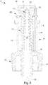
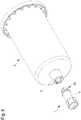
Figure 1 is an axonometric view of the connector according to the invention;Figure 2 is an axonometric view of a manufacturing step of the connector according to the invention;Figure 3 is a longitudinal section view of the connector according to the invention, before the deformation step of the manufacturing step;Figure 4 is the view ofFigure 3 in a next step;Figure 5 is an axonometric view of the connector and of a syringe before their coupling;Figure 6 is a longitudinal section view of the connector according to the invention which is moved close to the syringe; andFigure 7 is the view of the previous illustration, wherein the connector is coupled to the syringe.- With reference to these figures, globally indicated by 1 is the needle-free connector of the invention.
- The proposed
connector 1 is intended for use with an infusion line, especially of the type comprising an intravenous catheter or of the type made up of or comprising a medical bag or the like. - In practice, the connector is an inlet valve for the administration of medical fluids or saline solution, etc.
- In detail, the
connector 1 is of the type adapted to receive the outlet sleeve 2 (ortaper) of the needle-free syringe 3 containing the above-mentioned fluid. - The
connector 1 comprises acontainment body 4 which can be coupled, preferably in a releasable way, both to said infusion line and to saidsyringe 3. - Preferably, this occurs by using locking systems of the Luer lock type or the like.
- In detail, at its
distal end 20, intended for coupling to thesyringe 3, and at itsproximal end 19, intended for coupling to the catheter, theconnector 1 has threaded coupling means that can be of the Luer lock type or the like. - Herein below, for more convenient exposition but without loss of general information, reference will be made to the case wherein the infusion line is made up of the above-mentioned catheter, connected at one end to a vessel of a patient while at the other end it is coupled to the
connector 1. - In practice, as is known, the patient's circulatory system remains connected to the catheter, while the
syringe 3 is coupled to theconnector 1 only when a substance has to be administered. - At the end of administration, the
syringe 3 is separated from theconnector 1. Thecontainment body 4 ofconnector 1 is hollow and comprises anentry 7 to its internal volume. - The
containment body 4 is preferably made of polycarbonate or other plastic material. - The
body 4 comprises ahousing 5, of tubular shape, intended to be coupled to thesyringe 3, in the way explained above. - The
housing 5 has abase 6, at its own proximal end, and anentry 7 at the oppositedistal end 11, i.e. at the free end. - The
connector 1 of the invention comprises apipe connector 1. - In practice, the
pipe body 4 in communication with the catheter. - In turn, the
pipe tubular element 8, substantially needle shaped, having at least anaccess base 6 into thehousing 5, to define between thetubular element 8 and thehousing 5 itself a chamber, which is closed at thebase 6. - Furthermore, the
pipe outlet tang 17, communicating with thetubular element 8, suitable for being coupled sealed to the catheter. Preferably, as clearly shown in the illustrations,tang 17 andtubular element 8 are coaxial. - In practice, the
pipe above base 6 to define thetubular element 8 and thetang 17. - The
tubular element 8 therefore protrudes from thebase 6 towards the inside of thehousing 5, so that between the external side surface thereof and the internal lateral surface of the housing 5 a chamber is identified which is closed at thebase 6. - Preferably, the
housing 5 and thepipe - The
tubular element 8 is shorter than thehousing 5 and itsfree end 11 does not protrude from the above-mentionedentry 7 and is in fact separate from this and located inside thehousing 5. - Always preferably, the
tubular element 8 is tapered towards itsfree end 11, which can be pointed. - Even more in detail, the
tubular element 8 comprises one or more access throughholes dynamic path 12 which originates from saidholes tubular element 8 and thetang 17 and terminates in theexit 13 of the latter intended, during use, to be located within the catheter. - In practice, said fluid-dynamic path is defined by an
inner channel 12 obtained axially to theconnector 1, whichchannel 12 crosses the length of thepipe - Preferably, the
body 4 ofconnector 1 is, in its entirety, axial-symmetric. - The
connector 1 comprises asealing element 14, this too preferably axial-symmetric, contained in thehousing 5. - The sealing
element 14 is suitable for moving between an occlusion position wherein it seals theentry 7 of thehousing 5, preventing the fluid-dynamic communication between the outside of theconnector 1 and the aforementioned fluid-dynamic path 12, and an opening position wherein it frees theentry 7. - The sealing
element 14 is fitted sealed over thetubular element 8. - In detail, in its occlusion position, the sealing
element 14 obstructs theaccess tubular element 8. - The
connector 1 is constituted by only two members made up of thecontainment body 4 and of the sealingelement 14, each of which is made in a single body piece. - This way, the clearance is eliminated or drastically reduced between the different parts of the invention and the drawbacks of prior art are overcome.
- The
housing 5 shapes, at itsdistal end 11, an inwardly foldedportion 18 so as to define theaforementioned entry 7. - The
housing 5 is tubular and, in this case, the foldedportion 18 has an annular shape to define centrally the above-mentionedentry 7 of thebody 4 of theconnector 1. - In particular, the
housing 5 can be substantially cylindrical. - In this case, the
entry 7 has smaller dimensions than the inner section of thehousing 5 which can also be constant along its entire length. - For the purpose of making a
connector 1 which is made up of only two pieces but which also comprises such foldedportion 18, the invention envisages a manufacturing method which comprises the steps explained below. - First of all, the
containment body 4 of theconnector 1 is provided, comprising thehousing 5 described above and the sealing element 14 (seefigure 2 ) is provided. - The sealing
element 14 is inserted in thehousing 5 so thetubular element 8 fits into the sealingelement 14 itself, to obtain the reciprocal configurations already explained in the next paragraphs (seefigure 3 ). - After which, a portion of the
housing 5, comprising the above open anddistal end 11, is heated so as to soften it. - Such heating can e.g. be done by means of the use of ultra-sounds.
- At this point, the heated portion is deformed to define the above folded portion 18 (see
fig. 4 ). - Also note that the method of the invention can also envisage a cold deformation of the above extremal portion of the
housing 5. - The sealing
element 14 of the invention comprises anocclusion portion 15 which plugs the above-mentioned chamber, to define a pneumatic spring. - The chamber of the
housing 5 comprises air and, since it is closed at thebase 6, as explained above, and since it is plugged by theocclusion portion 15 of the sealingelement 14, a closed space, orinter-space 21, is created in it, which provides resistance to the compression caused by the shift of the sealingelement 14. - To be precise,
such occlusion portion 15 completely occupies, instant by instant, a section of the chamber, i.e., one of its longitudinal portions. - At the time of describing the operation of the invention, it will be explained how such pneumatic spring helps achieve the proposed objects.
- The sealing
element 14 is flexible, and preferably made of a yielding and in particular compressible material, e.g., silicone. - In detail, the sealing
element 14 is fitted tightly over thetubular element 8 and, completely covers it when it is in its occlusion position. - The sealing element comprises a
sheath 14 which tightly covers the external surface of thetubular element 8. - In this case, the sealing
element 14 can comprise a cavity, preferably blind, suitable for housing at least a distal portion of thetubular element 8 comprising its free end. - In practice, the sheath can internally shape a cavity, e.g., with a shape complementary to that of the
tubular element 8, which cavity, when idle, can have smaller dimensions than those of such element. - This way, once the sealing
element 14 has been fitted over thetubular element 8, the flexible characteristics of the former hold it firmly onto the latter. - In particular, the sheath is coupled with interference to the
tubular element 8. - The sheath shapes a thickened
head 15 comprising the above-mentioned occlusion portion. - In this case, the sealing
element 14 can also comprise athinner tail 16 than thehead 15, shaped like a sleeve, whichtail 16 extends between thehead 15 and thebase 6 of thehousing 5. - In practice, the
head 15 abuts with interference the internal lateral surface of thehousing 5, and therefore of the chamber, and is suitable for sliding along saidtubular element 8, without the continuous adhesion between sheath andtubular element 8 ever failing. - The above mentioned folded
portion 18 abuts thehead 15, crushing it, when it is in the above occlusion position. - Consequently, the pneumatic spring is also preloaded when it is in "idle" position, which is more precisely the position of maximum extension, which corresponds to the occlusion position of the sealing
element 14. - This aspect not only contributes in general to the sealed isolation of the inside of
connector 1, but in detail helps to ensure that the only space subject to change in pressure inside theconnector 1 is always and only that placed outside the sheath, i.e., in the inter-space 21 defined around it. - The preload helps keep the
sheath 14 adhered on thetubular element 8, because it experiments a pressure from the outside towards the inside which keeps it abutted with the surface of thetubular element 8. - The
access tubular element 8 are placed in distal portion of thetubular element 8, thehead 15 of the sealingelement 14 closes and seals, at the same time, such accesses and theentry 7 of thehousing 5, when the sealingelement 14 is in occlusion position. - In an embodiment not shown, the
sheath 14, at one or more points along the above-mentionedtail 16, has a number of ribs or grooves to obtain its programmed deformation. - Said ribs or grooves can be obtained at the external surface (facing the inter-space 21) or the inner surface (i.e., in the above-mentioned inner cavity) of the sheath itself.
- This solution facilitates both the collapse and the elastic return in the initial configuration of the
sheath 14. - Herein below, for convenience of exposure and without loss of general information, reference will be made to the preferred case wherein the tubular element is a
pointed needle 8 having a number of above-mentioned side holes arranged at its free distal end. - In this case, the
head 15 of thesheath 14 makes up a distal end of the sealingelement 14 through which theneedle 8 or better its pointeddistal end 11 can penetrate. - Consequently, when the
sheath 14 is in the occlusion position, thehead 15 surrounds and surmounts the tip of theneedle 8, extending above it until it closes theaccess needle 8 and thehousing 5 to plug the chamber. - In detail, the distal portion of the
needle 8 which comprises theaccesses head 15, when the sealingelement 14 is in the occlusion position and thehead 15 is therefore at the distal portion of thehousing 5 abutted with its foldedportion 18. - When the sealing
element 14 moves towards the opening position, according to the procedures shown below, thehead 15 moves towards thebase 6 of thehousing 5, allowing itself to be perforated by the tip of theneedle 8 and surpassing the distal portion of the latter, so as to free theentry 7 of thehousing 5 and the accesses of theneedle 8, while however keeping sealed the above-mentionedinter-space 21 which helps define the pneumatic spring. - In practice, the elasticity characteristics of the
head 15 are such that theneedle 8 is able to perforate it through a deformable orifice formed in it, which orifice closes again automatically, sealing itself, when the sealingelement 14 returns to the occlusion position and theneedle 8 therefore exits from the channel. - While the
head 15 is pierced by theneedle 8, the side walls of the latter are always very adhered onto the orifice, so as to prevent any flow of fluids, including air, through the orifice itself. - It must be noticed that the fact that the
needle 8 comprises a tip without openings at its top, which tip penetrates thehead 15 of thesheath 14 also when this is in the occlusion position, permits avoiding having empty spaces or discontinuities between theneedle 8 and thehead 15, wherein air or other fluids could trickle, thus germinating pathogens and in any case potentially compromising the isolation of the fluid-dynamic path 12 from the non-sterilized external environment. - In an embodiment of the invention not shown here, the
housing 5 comprises, at itsbase 6, at least a groove wherein the proximal end of thesheath 14 is interference fitted. - In practice, the edge of the proximal end, which preferably identifies a ring around the
needle 8, is fastened within a groove obtained for the purpose in thebase 6, so as to assist the tight adhesion ofsheath 14 to the external surface of theneedle 8. - The operation of the invention is described below.
- Initially, the
connector 1 is connected to the catheter at itsproximal end 19, while itsdistal end 20 which comprises theentry 7 is free. - The
entry 7 is closed by the sealingelement 14 which, in this step, is in the occlusion position, where it isolates and seals the above fluid-dynamic path 12. Every time the medical staff members have to administer a substance, they couple thesyringe 3 to thehousing 5 causing its dispensingsleeve 2 to penetrate through theentry 7. - This way, the
sleeve 2, or taper, of thesyringe 3 presses against thehead 15 of the sealingelement 14, moving it along theneedle 8 in the direction of the several times mentioned base 6 (seefigure 7 ). - In this step, the distal portion of the
needle 8 is uncovered, and thesleeve 2 of thesyringe 3 receives it internally. - When the sealing
element 14 reaches the opening position, thesleeve 2 of thesyringe 3 also internally comprises theaccesses needle 8. - The dimensions and the shape of
needle 8 andsleeve 2 are selected in such a way that the former fits sealed into the latter. - In this step, the pneumatic spring is loaded, by effect of both the compression of the air contained in the
above inter-space 21, and of the elasticity of the sealing element itself. - In sliding along the
needle 8, thesheath 14 always remains substantially strongly adhered to it, including thanks to the increase in pressure inside the inter-space 21 which compresses thesheath 14 against the external surface of theneedle 8. - This way, no empty space is created between sealing
element 14 andneedle 8 or betweenneedle 8 andsleeve 2. - In this step, the fluid-
dynamic path 12 defined within theconnector 1 places the inside of thesyringe 3 in communication with the catheter. - Consequently, the health worker injects the envisaged dose of fluid from the
syringe 3 to the catheter passing through theconnector 1. - At this point, the operator extracts the
sleeve 2 from thehousing 5 of theconnector 1. - Advantageously, the sealing
element 14 climbs back up along theneedle 8, as thesleeve 2 is gradually removed from the latter, without delay and without therefore allowing an empty space to form betweensleeve 2,needle 8 and sealingelement 14, especially at the distal portion of theneedle 8. - This way, when the
sleeve 2 passes by the accesses, the fluid included in the fluid-dynamic path 12 does not undergo any appreciable aspiration in the direction of the accesses of theneedle 8 and, consequently, no negative displacement is produced of the blood within the catheter, except to a negligible extent. - What is more, the invention completely prevents the occurrence of positive displacements.
Claims (6)
- Needle-free connector (1) for an infusion line, comprising:- a containment body (4) which can be coupled to said line, comprising at least an entry (7) and comprising at least an internal pipe (8, 17) suitable for the fluid-dynamic communication with said entry (7) and with said line; and- a sealing element (14) suitable for moving between an occlusion position wherein it seals said entry (7) and an opening position wherein it frees said entry (7);wherein:- said body (4) shapes a housing (5) having a base (6) at one proximal end and said entry (7) at the opposite distal end (20);- said body (4) shapes internally a tubular element (8) having at least an access (9, 10), which tubular element (8) is part of said pipe (8, 17),- said tubular element (8) is arranged within said housing (5) and protrudes from said base (6) of the housing (5) so as to define an internal chamber closed at said base (6),- said housing (5) shapes, at said distal end (20), an inwardly folded portion (18) so as to define said entry (7); and- said housing (5) is tubular and said folded portion (18) has an annular shape and defines centrally said entry (7),- said sealing element (14) is flexible and comprises a sheath (14) which tightly covers the external surface of said tubular element (8), andsaid sealing element (14) comprises at least an occlusion portion (15) which plugs said chamber sealed, to define a pneumatic spring, and wherein the sheath (14) shapes a thickened head (15) which comprises said occlusion portion (15), which abuts the internal lateral surface of said housing (5) and which is suitable for sliding along said tubular element (8)characterized in that the needle-free connector (1) is constituted by only two members, which are said body (4) and said sealing element (14) each of which is made in a single body piece; and said folded portion (18) abuts said occlusion portion (15) when the latter is in said occlusion position so that said pneumatic spring is preloaded when said sealing element (14) is in its idle position, wherein said idle position involves the sealing member being at the position of maximum extension, which corresponds to said occlusion position.
- Connector (1) according to claim 1characterized by the fact that said body (4) is axial-symmetric.
- Connector (1) according to claim 1 or 2,characterized by the fact that said housing (5) comprises, at said base (6), at least a groove wherein a proximal end of said sheath (14) is interference fitted.
- Method to make a needle-free connector (1) for an infusion line, as defined in claims 1-3, wherein the method comprises the steps of:- providing a containment body (4) made of plastic material, which can be coupled to said line, is made in a single body piece and comprises: at least a housing (5) having an open end, and at least an internal pipe (8, 17) suitable for the fluid-dynamic communication with said housing (5) and with said line;- inserting completely a sealing element (14) in said housing (5) through said open end, said sealing element (14) being made in a single body piece; and- after said inserting, deforming a portion of said housing (5) comprising said open end, so as to define an inwardly folded portion (18) that abuts the sealing element (14) and keeps the sealing element (14) preloaded,wherein:- said housing (5) has a base (6) at one proximal end and an entry (7) at the opposite distal end (20);- said housing (5) shapes, at said distal end (20), said inwardly folded portion (18) so as to define said entry (7); and- said housing (5) is tubular and said folded portion (18) has an annular shape and defines centrally said entry (7), and- said connector (1) is constituted by only two members which are said body (4) and said sealing element (14), each of which is made in a single body piece.
- Method according to claim 4,characterized by the fact that, before said deforming, said portion of the housing (5) is heated so as to soften it.
- Method according to claim 5,characterized by the fact that said portion of the housing (5) is heated by means of the use of ultra-sounds.
Applications Claiming Priority (2)
| Application Number | Priority Date | Filing Date | Title |
|---|---|---|---|
| IT000264AITMO20130264A1 (en) | 2013-09-25 | 2013-09-25 | CONNECTOR WITHOUT NEEDLE |
| PCT/IB2014/064563WO2015044835A1 (en) | 2013-09-25 | 2014-09-16 | Needle-free connector |
Publications (2)
| Publication Number | Publication Date |
|---|---|
| EP3049146A1 EP3049146A1 (en) | 2016-08-03 |
| EP3049146B1true EP3049146B1 (en) | 2019-02-06 |
Family
ID=49519046
Family Applications (1)
| Application Number | Title | Priority Date | Filing Date |
|---|---|---|---|
| EP14777863.3ANot-in-forceEP3049146B1 (en) | 2013-09-25 | 2014-09-16 | Needle-free connector |
Country Status (6)
| Country | Link |
|---|---|
| US (1) | US20160235961A1 (en) |
| EP (1) | EP3049146B1 (en) |
| ES (1) | ES2724299T3 (en) |
| IT (1) | ITMO20130264A1 (en) |
| TR (1) | TR201906156T4 (en) |
| WO (1) | WO2015044835A1 (en) |
Families Citing this family (13)
| Publication number | Priority date | Publication date | Assignee | Title |
|---|---|---|---|---|
| US8323249B2 (en) | 2009-08-14 | 2012-12-04 | The Regents Of The University Of Michigan | Integrated vascular delivery system |
| WO2011146769A2 (en) | 2010-05-19 | 2011-11-24 | Tangent Medical Technologies Llc | Integrated vascular delivery system |
| US8814833B2 (en) | 2010-05-19 | 2014-08-26 | Tangent Medical Technologies Llc | Safety needle system operable with a medical device |
| EP2916905A4 (en) | 2012-11-12 | 2016-11-09 | Icu Medical Inc | MEDICAL CONNECTION |
| JP6370364B2 (en) | 2013-03-15 | 2018-08-08 | アイシーユー・メディカル・インコーポレーテッド | Medical connector |
| AU2014364218B2 (en) | 2013-12-11 | 2019-06-06 | Icu Medical, Inc. | Check valve |
| CA2937744C (en) | 2014-02-04 | 2022-08-09 | Icu Medical, Inc. | Self-priming systems and methods |
| USD793551S1 (en) | 2014-12-03 | 2017-08-01 | Icu Medical, Inc. | Fluid manifold |
| USD786427S1 (en) | 2014-12-03 | 2017-05-09 | Icu Medical, Inc. | Fluid manifold |
| US20190030264A1 (en)* | 2017-07-27 | 2019-01-31 | Disruptive Medical Technologies, LLC | Luer Lock Adapter for MDI |
| IT201800020965A1 (en) | 2018-12-21 | 2020-06-21 | Pierc Di Giovanelli Gabriele E C S A S | NEEDLE-FREE CONNECTOR FOR INFUSION LINES |
| CN110694137B (en)* | 2019-11-04 | 2021-10-01 | 上海康德莱企业发展集团股份有限公司 | Seamless filling needle-free dosing connector |
| SE545166C2 (en) | 2020-06-24 | 2023-04-25 | Cyto365 Ab | A closed-system type female connector, a method for manufacture, and a stopcock having such female connectors |
Family Cites Families (42)
| Publication number | Priority date | Publication date | Assignee | Title |
|---|---|---|---|---|
| US4219912A (en)* | 1978-10-10 | 1980-09-02 | Baxter Travenol Laboratories, Inc. | Injection site having thermoplastically sealed injection port |
| US5695466A (en)* | 1993-07-23 | 1997-12-09 | Icu Medical, Inc. | Medical connection indicator and method of use |
| CA2124822C (en)* | 1991-12-18 | 2007-07-03 | George A. Lopez | Medical valve |
| US5694686A (en)* | 1991-12-18 | 1997-12-09 | Icu Medical, Inc. | Method for assembling a medical valve |
| US5279571A (en)* | 1991-12-30 | 1994-01-18 | Abbott Laboratories | Access site for fluid delivery system |
| US5351383A (en)* | 1992-07-29 | 1994-10-04 | Minnesota Mining And Manufacturing Company | Method of making an injection or sampling site |
| US5699821A (en)* | 1993-10-13 | 1997-12-23 | Paradis; Joseph R. | Control of fluid flow |
| US7033339B1 (en)* | 1998-05-29 | 2006-04-25 | Becton Dickinson And Company (Part Interest) | Self sealing luer receiving stopcock |
| US5549566A (en)* | 1994-10-27 | 1996-08-27 | Abbott Laboratories | Valved intravenous fluid line infusion device |
| NZ286445A (en)* | 1995-05-16 | 1997-12-19 | Ivac Corp | Needleless luer connector: deformable piston occludes bore |
| US5700248A (en)* | 1995-12-15 | 1997-12-23 | Icu Medical, Inc. | Medical valve with tire seal |
| US5885495A (en)* | 1996-12-19 | 1999-03-23 | Ibar; Jean-Pierre | Viscosity control for molten plastics prior to molding |
| US6050978A (en)* | 1997-05-09 | 2000-04-18 | Becton Dickinson And Company | Needleless valve connector |
| US5921264A (en)* | 1997-08-28 | 1999-07-13 | Paradis; Joseph R. | Swabbable needleless valve |
| US6029946A (en)* | 1997-09-15 | 2000-02-29 | Tiva Medical Inc. | Needleless valve |
| US6113068A (en)* | 1998-10-05 | 2000-09-05 | Rymed Technologies | Swabbable needleless injection port system having low reflux |
| JP3935292B2 (en)* | 1999-09-16 | 2007-06-20 | テルモ株式会社 | connector |
| US7044441B2 (en)* | 2001-08-10 | 2006-05-16 | Cardinal Health 303, Inc. | Valved male luer connector having sequential valve timing |
| US7160272B1 (en)* | 2002-05-31 | 2007-01-09 | Elcam Plastic | Y-site medical valve |
| US7118560B2 (en)* | 2003-02-28 | 2006-10-10 | Creative Plastic Technology, Llc | Needleless Luer activated medical connector |
| EP1721632A4 (en)* | 2003-07-09 | 2013-02-20 | Jms Co Ltd | Mixed injection port |
| US6834649B1 (en)* | 2004-04-13 | 2004-12-28 | Tzong-Fuh Kuo | One-way valve on diving mask |
| US7670322B2 (en)* | 2005-02-01 | 2010-03-02 | Icu Medical, Inc. | Check valve for medical Y-site |
| US20080197626A1 (en)* | 2005-05-16 | 2008-08-21 | David Coambs | Coupling Device for Medical Lines |
| US8377010B2 (en)* | 2005-11-17 | 2013-02-19 | Becton, Dickinson And Company | Medical access device |
| ITTO20060206A1 (en)* | 2006-03-17 | 2007-09-18 | Borla Ind | VALVE VALVE FOR MEDICAL LINES |
| US20070225647A1 (en)* | 2006-03-23 | 2007-09-27 | Luther Ronald B | Flush entrance hemostasis valve with unobstructed passageway |
| US7753338B2 (en)* | 2006-10-23 | 2010-07-13 | Baxter International Inc. | Luer activated device with minimal fluid displacement |
| BRPI0717401A2 (en)* | 2006-10-25 | 2013-11-12 | Icu Medical Inc | CONNECTOR FOR MEDICAL USE |
| JP5290630B2 (en)* | 2007-06-05 | 2013-09-18 | ニプロ株式会社 | Medical connector and manufacturing method thereof |
| US20090209922A1 (en)* | 2008-02-15 | 2009-08-20 | Nypro Inc. | Self-Lubricating Elastomeric Components for Use in Medical Devices |
| ITTO20080381A1 (en)* | 2008-05-21 | 2009-11-22 | Industrie Borla Spa | VALVE VALVE FOR MEDICAL LINES |
| US9168366B2 (en)* | 2008-12-19 | 2015-10-27 | Icu Medical, Inc. | Medical connector with closeable luer connector |
| US8454579B2 (en)* | 2009-03-25 | 2013-06-04 | Icu Medical, Inc. | Medical connector with automatic valves and volume regulator |
| WO2010121741A1 (en)* | 2009-04-23 | 2010-10-28 | Fresenius Medical Care Deutschland Gmbh | Valve device, valve core, external functional device, treatment device as well as method |
| WO2012162259A2 (en)* | 2011-05-20 | 2012-11-29 | Excelsior Medical Corporation | Caps for cannula access devices |
| US9867975B2 (en)* | 2011-05-23 | 2018-01-16 | Excelsior Medical Corporation | Antiseptic line cap |
| US10166381B2 (en)* | 2011-05-23 | 2019-01-01 | Excelsior Medical Corporation | Antiseptic cap |
| TWM480392U (en)* | 2013-10-16 | 2014-06-21 | Yi Jin Promold Entpr Ltd | Anti-backflow medical connector |
| AU2014364218B2 (en)* | 2013-12-11 | 2019-06-06 | Icu Medical, Inc. | Check valve |
| CA2937744C (en)* | 2014-02-04 | 2022-08-09 | Icu Medical, Inc. | Self-priming systems and methods |
| DE102014103507A1 (en)* | 2014-03-14 | 2015-09-17 | Fresenius Medical Care Deutschland Gmbh | Medical functional device with a valve seat for a remanentes check valve |
- 2013
- 2013-09-25ITIT000264Apatent/ITMO20130264A1/enunknown
- 2014
- 2014-09-16WOPCT/IB2014/064563patent/WO2015044835A1/enactiveApplication Filing
- 2014-09-16USUS15/024,685patent/US20160235961A1/ennot_activeAbandoned
- 2014-09-16EPEP14777863.3Apatent/EP3049146B1/ennot_activeNot-in-force
- 2014-09-16ESES14777863Tpatent/ES2724299T3/enactiveActive
- 2014-09-16TRTR2019/06156Tpatent/TR201906156T4/enunknown
Non-Patent Citations (1)
| Title |
|---|
| None* |
Also Published As
| Publication number | Publication date |
|---|---|
| ITMO20130264A1 (en) | 2015-03-26 |
| ES2724299T3 (en) | 2019-09-10 |
| US20160235961A1 (en) | 2016-08-18 |
| EP3049146A1 (en) | 2016-08-03 |
| WO2015044835A1 (en) | 2015-04-02 |
| TR201906156T4 (en) | 2019-05-21 |
Similar Documents
| Publication | Publication Date | Title |
|---|---|---|
| EP3049146B1 (en) | Needle-free connector | |
| US11565088B2 (en) | Multi-use blood control safety catheter assembly | |
| US11452858B2 (en) | Intravenous catheter with pressure activated valve | |
| US7037302B2 (en) | Positive flow needleless connector | |
| US7938805B2 (en) | Radially compressible blood control valve | |
| US5154703A (en) | Bloodless catheter | |
| JP6302104B1 (en) | Medical infusion connector | |
| JPH09182790A (en) | Adapter with valve for medical access device | |
| CN203724591U (en) | Valve-controlled catheter assembly | |
| EP3593852B1 (en) | Iv catheter assemblies with injection ports | |
| US8540682B2 (en) | Plunger activated capping system | |
| CN107635618A (en) | Catheter assembly with flow control valve mechanism and related methods | |
| EP3707422B1 (en) | Pressure spike absorbing systems | |
| WO2015044834A1 (en) | Needle-free connector | |
| JP7728282B2 (en) | Dual Chamber Syringe Assembly | |
| US20250235673A1 (en) | Catheter devices with valves and related methods | |
| CN115968308B (en) | Device for fluidly connecting a medical container to a connector and method of manufacturing the device | |
| HK40055713A (en) | Iv catheter assemblies with injection ports | |
| HK40055713B (en) | Iv catheter assemblies with injection ports | |
| HK1241304A1 (en) | Iv catheter assemblies with injection ports | |
| GB2535757A (en) | IV catheter assemblies with injection ports and related methods | |
| GB2535759A (en) | IV catheter assemblies with injection ports and related methods |
Legal Events
| Date | Code | Title | Description |
|---|---|---|---|
| PUAI | Public reference made under article 153(3) epc to a published international application that has entered the european phase | Free format text:ORIGINAL CODE: 0009012 | |
| 17P | Request for examination filed | Effective date:20160418 | |
| AK | Designated contracting states | Kind code of ref document:A1 Designated state(s):AL AT BE BG CH CY CZ DE DK EE ES FI FR GB GR HR HU IE IS IT LI LT LU LV MC MK MT NL NO PL PT RO RS SE SI SK SM TR | |
| AX | Request for extension of the european patent | Extension state:BA ME | |
| DAX | Request for extension of the european patent (deleted) | ||
| STAA | Information on the status of an ep patent application or granted ep patent | Free format text:STATUS: EXAMINATION IS IN PROGRESS | |
| 17Q | First examination report despatched | Effective date:20171020 | |
| GRAP | Despatch of communication of intention to grant a patent | Free format text:ORIGINAL CODE: EPIDOSNIGR1 | |
| STAA | Information on the status of an ep patent application or granted ep patent | Free format text:STATUS: GRANT OF PATENT IS INTENDED | |
| INTG | Intention to grant announced | Effective date:20180823 | |
| GRAS | Grant fee paid | Free format text:ORIGINAL CODE: EPIDOSNIGR3 | |
| RAP1 | Party data changed (applicant data changed or rights of an application transferred) | Owner name:PIERC S.R.L. | |
| GRAA | (expected) grant | Free format text:ORIGINAL CODE: 0009210 | |
| STAA | Information on the status of an ep patent application or granted ep patent | Free format text:STATUS: THE PATENT HAS BEEN GRANTED | |
| AK | Designated contracting states | Kind code of ref document:B1 Designated state(s):AL AT BE BG CH CY CZ DE DK EE ES FI FR GB GR HR HU IE IS IT LI LT LU LV MC MK MT NL NO PL PT RO RS SE SI SK SM TR | |
| REG | Reference to a national code | Ref country code:GB Ref legal event code:FG4D | |
| REG | Reference to a national code | Ref country code:CH Ref legal event code:EP Ref country code:AT Ref legal event code:REF Ref document number:1094467 Country of ref document:AT Kind code of ref document:T Effective date:20190215 | |
| REG | Reference to a national code | Ref country code:IE Ref legal event code:FG4D | |
| REG | Reference to a national code | Ref country code:DE Ref legal event code:R096 Ref document number:602014040761 Country of ref document:DE | |
| REG | Reference to a national code | Ref country code:NL Ref legal event code:MP Effective date:20190206 | |
| REG | Reference to a national code | Ref country code:LT Ref legal event code:MG4D | |
| PG25 | Lapsed in a contracting state [announced via postgrant information from national office to epo] | Ref country code:NL Free format text:LAPSE BECAUSE OF FAILURE TO SUBMIT A TRANSLATION OF THE DESCRIPTION OR TO PAY THE FEE WITHIN THE PRESCRIBED TIME-LIMIT Effective date:20190206 Ref country code:SE Free format text:LAPSE BECAUSE OF FAILURE TO SUBMIT A TRANSLATION OF THE DESCRIPTION OR TO PAY THE FEE WITHIN THE PRESCRIBED TIME-LIMIT Effective date:20190206 Ref country code:LT Free format text:LAPSE BECAUSE OF FAILURE TO SUBMIT A TRANSLATION OF THE DESCRIPTION OR TO PAY THE FEE WITHIN THE PRESCRIBED TIME-LIMIT Effective date:20190206 Ref country code:PT Free format text:LAPSE BECAUSE OF FAILURE TO SUBMIT A TRANSLATION OF THE DESCRIPTION OR TO PAY THE FEE WITHIN THE PRESCRIBED TIME-LIMIT Effective date:20190606 Ref country code:NO Free format text:LAPSE BECAUSE OF FAILURE TO SUBMIT A TRANSLATION OF THE DESCRIPTION OR TO PAY THE FEE WITHIN THE PRESCRIBED TIME-LIMIT Effective date:20190506 Ref country code:FI Free format text:LAPSE BECAUSE OF FAILURE TO SUBMIT A TRANSLATION OF THE DESCRIPTION OR TO PAY THE FEE WITHIN THE PRESCRIBED TIME-LIMIT Effective date:20190206 | |
| REG | Reference to a national code | Ref country code:AT Ref legal event code:MK05 Ref document number:1094467 Country of ref document:AT Kind code of ref document:T Effective date:20190206 | |
| PG25 | Lapsed in a contracting state [announced via postgrant information from national office to epo] | Ref country code:BG Free format text:LAPSE BECAUSE OF FAILURE TO SUBMIT A TRANSLATION OF THE DESCRIPTION OR TO PAY THE FEE WITHIN THE PRESCRIBED TIME-LIMIT Effective date:20190506 Ref country code:HR Free format text:LAPSE BECAUSE OF FAILURE TO SUBMIT A TRANSLATION OF THE DESCRIPTION OR TO PAY THE FEE WITHIN THE PRESCRIBED TIME-LIMIT Effective date:20190206 Ref country code:RS Free format text:LAPSE BECAUSE OF FAILURE TO SUBMIT A TRANSLATION OF THE DESCRIPTION OR TO PAY THE FEE WITHIN THE PRESCRIBED TIME-LIMIT Effective date:20190206 Ref country code:GR Free format text:LAPSE BECAUSE OF FAILURE TO SUBMIT A TRANSLATION OF THE DESCRIPTION OR TO PAY THE FEE WITHIN THE PRESCRIBED TIME-LIMIT Effective date:20190507 Ref country code:LV Free format text:LAPSE BECAUSE OF FAILURE TO SUBMIT A TRANSLATION OF THE DESCRIPTION OR TO PAY THE FEE WITHIN THE PRESCRIBED TIME-LIMIT Effective date:20190206 Ref country code:IS Free format text:LAPSE BECAUSE OF FAILURE TO SUBMIT A TRANSLATION OF THE DESCRIPTION OR TO PAY THE FEE WITHIN THE PRESCRIBED TIME-LIMIT Effective date:20190606 | |
| REG | Reference to a national code | Ref country code:ES Ref legal event code:FG2A Ref document number:2724299 Country of ref document:ES Kind code of ref document:T3 Effective date:20190910 | |
| PG25 | Lapsed in a contracting state [announced via postgrant information from national office to epo] | Ref country code:AL Free format text:LAPSE BECAUSE OF FAILURE TO SUBMIT A TRANSLATION OF THE DESCRIPTION OR TO PAY THE FEE WITHIN THE PRESCRIBED TIME-LIMIT Effective date:20190206 Ref country code:SK Free format text:LAPSE BECAUSE OF FAILURE TO SUBMIT A TRANSLATION OF THE DESCRIPTION OR TO PAY THE FEE WITHIN THE PRESCRIBED TIME-LIMIT Effective date:20190206 Ref country code:DK Free format text:LAPSE BECAUSE OF FAILURE TO SUBMIT A TRANSLATION OF THE DESCRIPTION OR TO PAY THE FEE WITHIN THE PRESCRIBED TIME-LIMIT Effective date:20190206 Ref country code:EE Free format text:LAPSE BECAUSE OF FAILURE TO SUBMIT A TRANSLATION OF THE DESCRIPTION OR TO PAY THE FEE WITHIN THE PRESCRIBED TIME-LIMIT Effective date:20190206 Ref country code:RO Free format text:LAPSE BECAUSE OF FAILURE TO SUBMIT A TRANSLATION OF THE DESCRIPTION OR TO PAY THE FEE WITHIN THE PRESCRIBED TIME-LIMIT Effective date:20190206 Ref country code:CZ Free format text:LAPSE BECAUSE OF FAILURE TO SUBMIT A TRANSLATION OF THE DESCRIPTION OR TO PAY THE FEE WITHIN THE PRESCRIBED TIME-LIMIT Effective date:20190206 | |
| REG | Reference to a national code | Ref country code:DE Ref legal event code:R097 Ref document number:602014040761 Country of ref document:DE | |
| PG25 | Lapsed in a contracting state [announced via postgrant information from national office to epo] | Ref country code:SM Free format text:LAPSE BECAUSE OF FAILURE TO SUBMIT A TRANSLATION OF THE DESCRIPTION OR TO PAY THE FEE WITHIN THE PRESCRIBED TIME-LIMIT Effective date:20190206 Ref country code:PL Free format text:LAPSE BECAUSE OF FAILURE TO SUBMIT A TRANSLATION OF THE DESCRIPTION OR TO PAY THE FEE WITHIN THE PRESCRIBED TIME-LIMIT Effective date:20190206 | |
| PLBE | No opposition filed within time limit | Free format text:ORIGINAL CODE: 0009261 | |
| STAA | Information on the status of an ep patent application or granted ep patent | Free format text:STATUS: NO OPPOSITION FILED WITHIN TIME LIMIT | |
| PG25 | Lapsed in a contracting state [announced via postgrant information from national office to epo] | Ref country code:AT Free format text:LAPSE BECAUSE OF FAILURE TO SUBMIT A TRANSLATION OF THE DESCRIPTION OR TO PAY THE FEE WITHIN THE PRESCRIBED TIME-LIMIT Effective date:20190206 | |
| 26N | No opposition filed | Effective date:20191107 | |
| PG25 | Lapsed in a contracting state [announced via postgrant information from national office to epo] | Ref country code:SI Free format text:LAPSE BECAUSE OF FAILURE TO SUBMIT A TRANSLATION OF THE DESCRIPTION OR TO PAY THE FEE WITHIN THE PRESCRIBED TIME-LIMIT Effective date:20190206 | |
| PG25 | Lapsed in a contracting state [announced via postgrant information from national office to epo] | Ref country code:MC Free format text:LAPSE BECAUSE OF FAILURE TO SUBMIT A TRANSLATION OF THE DESCRIPTION OR TO PAY THE FEE WITHIN THE PRESCRIBED TIME-LIMIT Effective date:20190206 | |
| PG25 | Lapsed in a contracting state [announced via postgrant information from national office to epo] | Ref country code:IE Free format text:LAPSE BECAUSE OF NON-PAYMENT OF DUE FEES Effective date:20190916 Ref country code:LU Free format text:LAPSE BECAUSE OF NON-PAYMENT OF DUE FEES Effective date:20190916 | |
| REG | Reference to a national code | Ref country code:BE Ref legal event code:MM Effective date:20190930 | |
| PG25 | Lapsed in a contracting state [announced via postgrant information from national office to epo] | Ref country code:BE Free format text:LAPSE BECAUSE OF NON-PAYMENT OF DUE FEES Effective date:20190930 | |
| PG25 | Lapsed in a contracting state [announced via postgrant information from national office to epo] | Ref country code:CY Free format text:LAPSE BECAUSE OF FAILURE TO SUBMIT A TRANSLATION OF THE DESCRIPTION OR TO PAY THE FEE WITHIN THE PRESCRIBED TIME-LIMIT Effective date:20190206 | |
| PG25 | Lapsed in a contracting state [announced via postgrant information from national office to epo] | Ref country code:HU Free format text:LAPSE BECAUSE OF FAILURE TO SUBMIT A TRANSLATION OF THE DESCRIPTION OR TO PAY THE FEE WITHIN THE PRESCRIBED TIME-LIMIT; INVALID AB INITIO Effective date:20140916 Ref country code:MT Free format text:LAPSE BECAUSE OF FAILURE TO SUBMIT A TRANSLATION OF THE DESCRIPTION OR TO PAY THE FEE WITHIN THE PRESCRIBED TIME-LIMIT Effective date:20190206 | |
| PGFP | Annual fee paid to national office [announced via postgrant information from national office to epo] | Ref country code:FR Payment date:20210927 Year of fee payment:8 Ref country code:IT Payment date:20210928 Year of fee payment:8 | |
| PGFP | Annual fee paid to national office [announced via postgrant information from national office to epo] | Ref country code:GB Payment date:20210927 Year of fee payment:8 Ref country code:DE Payment date:20210929 Year of fee payment:8 Ref country code:TR Payment date:20210901 Year of fee payment:8 | |
| PGFP | Annual fee paid to national office [announced via postgrant information from national office to epo] | Ref country code:ES Payment date:20211001 Year of fee payment:8 | |
| PGFP | Annual fee paid to national office [announced via postgrant information from national office to epo] | Ref country code:CH Payment date:20211004 Year of fee payment:8 | |
| PG25 | Lapsed in a contracting state [announced via postgrant information from national office to epo] | Ref country code:MK Free format text:LAPSE BECAUSE OF FAILURE TO SUBMIT A TRANSLATION OF THE DESCRIPTION OR TO PAY THE FEE WITHIN THE PRESCRIBED TIME-LIMIT Effective date:20190206 | |
| REG | Reference to a national code | Ref country code:DE Ref legal event code:R119 Ref document number:602014040761 Country of ref document:DE | |
| REG | Reference to a national code | Ref country code:CH Ref legal event code:PL | |
| GBPC | Gb: european patent ceased through non-payment of renewal fee | Effective date:20220916 | |
| PG25 | Lapsed in a contracting state [announced via postgrant information from national office to epo] | Ref country code:LI Free format text:LAPSE BECAUSE OF NON-PAYMENT OF DUE FEES Effective date:20220930 Ref country code:FR Free format text:LAPSE BECAUSE OF NON-PAYMENT OF DUE FEES Effective date:20220930 Ref country code:DE Free format text:LAPSE BECAUSE OF NON-PAYMENT OF DUE FEES Effective date:20230401 Ref country code:CH Free format text:LAPSE BECAUSE OF NON-PAYMENT OF DUE FEES Effective date:20220930 | |
| REG | Reference to a national code | Ref country code:ES Ref legal event code:FD2A Effective date:20231030 | |
| PG25 | Lapsed in a contracting state [announced via postgrant information from national office to epo] | Ref country code:IT Free format text:LAPSE BECAUSE OF NON-PAYMENT OF DUE FEES Effective date:20220916 Ref country code:GB Free format text:LAPSE BECAUSE OF NON-PAYMENT OF DUE FEES Effective date:20220916 | |
| PG25 | Lapsed in a contracting state [announced via postgrant information from national office to epo] | Ref country code:ES Free format text:LAPSE BECAUSE OF NON-PAYMENT OF DUE FEES Effective date:20220917 | |
| PG25 | Lapsed in a contracting state [announced via postgrant information from national office to epo] | Ref country code:ES Free format text:LAPSE BECAUSE OF NON-PAYMENT OF DUE FEES Effective date:20220917 | |
| PG25 | Lapsed in a contracting state [announced via postgrant information from national office to epo] | Ref country code:TR Free format text:LAPSE BECAUSE OF NON-PAYMENT OF DUE FEES Effective date:20220916 |