EP3048719B1 - Method for operating an assembly comprising a rotary work machine - Google Patents
Method for operating an assembly comprising a rotary work machineDownload PDFInfo
- Publication number
- EP3048719B1 EP3048719B1EP16000107.9AEP16000107AEP3048719B1EP 3048719 B1EP3048719 B1EP 3048719B1EP 16000107 AEP16000107 AEP 16000107AEP 3048719 B1EP3048719 B1EP 3048719B1
- Authority
- EP
- European Patent Office
- Prior art keywords
- drive machine
- rotating drive
- load
- arrangement
- change value
- Prior art date
- Legal status (The legal status is an assumption and is not a legal conclusion. Google has not performed a legal analysis and makes no representation as to the accuracy of the status listed.)
- Active
Links
Images

Classifications
- H—ELECTRICITY
- H02—GENERATION; CONVERSION OR DISTRIBUTION OF ELECTRIC POWER
- H02P—CONTROL OR REGULATION OF ELECTRIC MOTORS, ELECTRIC GENERATORS OR DYNAMO-ELECTRIC CONVERTERS; CONTROLLING TRANSFORMERS, REACTORS OR CHOKE COILS
- H02P9/00—Arrangements for controlling electric generators for the purpose of obtaining a desired output
- H02P9/04—Control effected upon non-electric prime mover and dependent upon electric output value of the generator
- F—MECHANICAL ENGINEERING; LIGHTING; HEATING; WEAPONS; BLASTING
- F02—COMBUSTION ENGINES; HOT-GAS OR COMBUSTION-PRODUCT ENGINE PLANTS
- F02D—CONTROLLING COMBUSTION ENGINES
- F02D41/00—Electrical control of supply of combustible mixture or its constituents
- F02D41/02—Circuit arrangements for generating control signals
- F02D41/04—Introducing corrections for particular operating conditions
- F02D41/10—Introducing corrections for particular operating conditions for acceleration
- F02D41/107—Introducing corrections for particular operating conditions for acceleration and deceleration
- F—MECHANICAL ENGINEERING; LIGHTING; HEATING; WEAPONS; BLASTING
- F02—COMBUSTION ENGINES; HOT-GAS OR COMBUSTION-PRODUCT ENGINE PLANTS
- F02B—INTERNAL-COMBUSTION PISTON ENGINES; COMBUSTION ENGINES IN GENERAL
- F02B53/00—Internal-combustion aspects of rotary-piston or oscillating-piston engines
- F02B53/12—Ignition
- F—MECHANICAL ENGINEERING; LIGHTING; HEATING; WEAPONS; BLASTING
- F02—COMBUSTION ENGINES; HOT-GAS OR COMBUSTION-PRODUCT ENGINE PLANTS
- F02B—INTERNAL-COMBUSTION PISTON ENGINES; COMBUSTION ENGINES IN GENERAL
- F02B53/00—Internal-combustion aspects of rotary-piston or oscillating-piston engines
- F02B53/14—Adaptations of engines for driving, or engine combinations with, other devices
- F—MECHANICAL ENGINEERING; LIGHTING; HEATING; WEAPONS; BLASTING
- F02—COMBUSTION ENGINES; HOT-GAS OR COMBUSTION-PRODUCT ENGINE PLANTS
- F02B—INTERNAL-COMBUSTION PISTON ENGINES; COMBUSTION ENGINES IN GENERAL
- F02B63/00—Adaptations of engines for driving pumps, hand-held tools or electric generators; Portable combinations of engines with engine-driven devices
- F02B63/04—Adaptations of engines for driving pumps, hand-held tools or electric generators; Portable combinations of engines with engine-driven devices for electric generators
- F02B63/042—Rotating electric generators
- F—MECHANICAL ENGINEERING; LIGHTING; HEATING; WEAPONS; BLASTING
- F02—COMBUSTION ENGINES; HOT-GAS OR COMBUSTION-PRODUCT ENGINE PLANTS
- F02D—CONTROLLING COMBUSTION ENGINES
- F02D19/00—Controlling engines characterised by their use of non-liquid fuels, pluralities of fuels, or non-fuel substances added to the combustible mixtures
- F02D19/02—Controlling engines characterised by their use of non-liquid fuels, pluralities of fuels, or non-fuel substances added to the combustible mixtures peculiar to engines working with gaseous fuels
- F—MECHANICAL ENGINEERING; LIGHTING; HEATING; WEAPONS; BLASTING
- F02—COMBUSTION ENGINES; HOT-GAS OR COMBUSTION-PRODUCT ENGINE PLANTS
- F02D—CONTROLLING COMBUSTION ENGINES
- F02D29/00—Controlling engines, such controlling being peculiar to the devices driven thereby, the devices being other than parts or accessories essential to engine operation, e.g. controlling of engines by signals external thereto
- F02D29/06—Controlling engines, such controlling being peculiar to the devices driven thereby, the devices being other than parts or accessories essential to engine operation, e.g. controlling of engines by signals external thereto peculiar to engines driving electric generators
- F—MECHANICAL ENGINEERING; LIGHTING; HEATING; WEAPONS; BLASTING
- F02—COMBUSTION ENGINES; HOT-GAS OR COMBUSTION-PRODUCT ENGINE PLANTS
- F02D—CONTROLLING COMBUSTION ENGINES
- F02D41/00—Electrical control of supply of combustible mixture or its constituents
- F02D41/0002—Controlling intake air
- F02D41/0007—Controlling intake air for control of turbo-charged or super-charged engines
- F—MECHANICAL ENGINEERING; LIGHTING; HEATING; WEAPONS; BLASTING
- F02—COMBUSTION ENGINES; HOT-GAS OR COMBUSTION-PRODUCT ENGINE PLANTS
- F02D—CONTROLLING COMBUSTION ENGINES
- F02D41/00—Electrical control of supply of combustible mixture or its constituents
- F02D41/02—Circuit arrangements for generating control signals
- F02D41/0205—Circuit arrangements for generating control signals using an auxiliary engine speed control
- F—MECHANICAL ENGINEERING; LIGHTING; HEATING; WEAPONS; BLASTING
- F02—COMBUSTION ENGINES; HOT-GAS OR COMBUSTION-PRODUCT ENGINE PLANTS
- F02D—CONTROLLING COMBUSTION ENGINES
- F02D41/00—Electrical control of supply of combustible mixture or its constituents
- F02D41/02—Circuit arrangements for generating control signals
- F02D41/021—Introducing corrections for particular conditions exterior to the engine
- F—MECHANICAL ENGINEERING; LIGHTING; HEATING; WEAPONS; BLASTING
- F02—COMBUSTION ENGINES; HOT-GAS OR COMBUSTION-PRODUCT ENGINE PLANTS
- F02D—CONTROLLING COMBUSTION ENGINES
- F02D41/00—Electrical control of supply of combustible mixture or its constituents
- F02D41/02—Circuit arrangements for generating control signals
- F02D41/14—Introducing closed-loop corrections
- F—MECHANICAL ENGINEERING; LIGHTING; HEATING; WEAPONS; BLASTING
- F02—COMBUSTION ENGINES; HOT-GAS OR COMBUSTION-PRODUCT ENGINE PLANTS
- F02D—CONTROLLING COMBUSTION ENGINES
- F02D41/00—Electrical control of supply of combustible mixture or its constituents
- F02D41/30—Controlling fuel injection
- F02D41/3005—Details not otherwise provided for
- F—MECHANICAL ENGINEERING; LIGHTING; HEATING; WEAPONS; BLASTING
- F02—COMBUSTION ENGINES; HOT-GAS OR COMBUSTION-PRODUCT ENGINE PLANTS
- F02M—SUPPLYING COMBUSTION ENGINES IN GENERAL WITH COMBUSTIBLE MIXTURES OR CONSTITUENTS THEREOF
- F02M21/00—Apparatus for supplying engines with non-liquid fuels, e.g. gaseous fuels stored in liquid form
- F02M21/02—Apparatus for supplying engines with non-liquid fuels, e.g. gaseous fuels stored in liquid form for gaseous fuels
- F—MECHANICAL ENGINEERING; LIGHTING; HEATING; WEAPONS; BLASTING
- F02—COMBUSTION ENGINES; HOT-GAS OR COMBUSTION-PRODUCT ENGINE PLANTS
- F02P—IGNITION, OTHER THAN COMPRESSION IGNITION, FOR INTERNAL-COMBUSTION ENGINES; TESTING OF IGNITION TIMING IN COMPRESSION-IGNITION ENGINES
- F02P9/00—Electric spark ignition control, not otherwise provided for
- F02P9/002—Control of spark intensity, intensifying, lengthening, suppression
- H—ELECTRICITY
- H02—GENERATION; CONVERSION OR DISTRIBUTION OF ELECTRIC POWER
- H02J—CIRCUIT ARRANGEMENTS OR SYSTEMS FOR SUPPLYING OR DISTRIBUTING ELECTRIC POWER; SYSTEMS FOR STORING ELECTRIC ENERGY
- H02J3/00—Circuit arrangements for AC mains or AC distribution networks
- H02J3/12—Circuit arrangements for AC mains or AC distribution networks for adjusting voltage in AC networks by changing a characteristic of the network load
- H02J3/14—Circuit arrangements for AC mains or AC distribution networks for adjusting voltage in AC networks by changing a characteristic of the network load by switching loads on to, or off from, network, e.g. progressively balanced loading
- F—MECHANICAL ENGINEERING; LIGHTING; HEATING; WEAPONS; BLASTING
- F02—COMBUSTION ENGINES; HOT-GAS OR COMBUSTION-PRODUCT ENGINE PLANTS
- F02B—INTERNAL-COMBUSTION PISTON ENGINES; COMBUSTION ENGINES IN GENERAL
- F02B37/00—Engines characterised by provision of pumps driven at least for part of the time by exhaust
- F02B37/12—Control of the pumps
- F02B37/16—Control of the pumps by bypassing charging air
- F—MECHANICAL ENGINEERING; LIGHTING; HEATING; WEAPONS; BLASTING
- F02—COMBUSTION ENGINES; HOT-GAS OR COMBUSTION-PRODUCT ENGINE PLANTS
- F02B—INTERNAL-COMBUSTION PISTON ENGINES; COMBUSTION ENGINES IN GENERAL
- F02B37/00—Engines characterised by provision of pumps driven at least for part of the time by exhaust
- F02B37/12—Control of the pumps
- F02B37/18—Control of the pumps by bypassing exhaust from the inlet to the outlet of turbine or to the atmosphere
- F—MECHANICAL ENGINEERING; LIGHTING; HEATING; WEAPONS; BLASTING
- F02—COMBUSTION ENGINES; HOT-GAS OR COMBUSTION-PRODUCT ENGINE PLANTS
- F02B—INTERNAL-COMBUSTION PISTON ENGINES; COMBUSTION ENGINES IN GENERAL
- F02B53/00—Internal-combustion aspects of rotary-piston or oscillating-piston engines
- F02B53/02—Methods of operating
- F—MECHANICAL ENGINEERING; LIGHTING; HEATING; WEAPONS; BLASTING
- F02—COMBUSTION ENGINES; HOT-GAS OR COMBUSTION-PRODUCT ENGINE PLANTS
- F02B—INTERNAL-COMBUSTION PISTON ENGINES; COMBUSTION ENGINES IN GENERAL
- F02B53/00—Internal-combustion aspects of rotary-piston or oscillating-piston engines
- F02B53/10—Fuel supply; Introducing fuel to combustion space
- F—MECHANICAL ENGINEERING; LIGHTING; HEATING; WEAPONS; BLASTING
- F02—COMBUSTION ENGINES; HOT-GAS OR COMBUSTION-PRODUCT ENGINE PLANTS
- F02D—CONTROLLING COMBUSTION ENGINES
- F02D19/00—Controlling engines characterised by their use of non-liquid fuels, pluralities of fuels, or non-fuel substances added to the combustible mixtures
- F02D19/02—Controlling engines characterised by their use of non-liquid fuels, pluralities of fuels, or non-fuel substances added to the combustible mixtures peculiar to engines working with gaseous fuels
- F02D19/021—Control of components of the fuel supply system
- F02D19/023—Control of components of the fuel supply system to adjust the fuel mass or volume flow
- F—MECHANICAL ENGINEERING; LIGHTING; HEATING; WEAPONS; BLASTING
- F02—COMBUSTION ENGINES; HOT-GAS OR COMBUSTION-PRODUCT ENGINE PLANTS
- F02D—CONTROLLING COMBUSTION ENGINES
- F02D41/00—Electrical control of supply of combustible mixture or its constituents
- F02D41/02—Circuit arrangements for generating control signals
- F02D41/14—Introducing closed-loop corrections
- F02D41/1401—Introducing closed-loop corrections characterised by the control or regulation method
- F02D2041/1433—Introducing closed-loop corrections characterised by the control or regulation method using a model or simulation of the system
- F—MECHANICAL ENGINEERING; LIGHTING; HEATING; WEAPONS; BLASTING
- F02—COMBUSTION ENGINES; HOT-GAS OR COMBUSTION-PRODUCT ENGINE PLANTS
- F02D—CONTROLLING COMBUSTION ENGINES
- F02D2200/00—Input parameters for engine control
- F02D2200/02—Input parameters for engine control the parameters being related to the engine
- F02D2200/10—Parameters related to the engine output, e.g. engine torque or engine speed
- F02D2200/101—Engine speed
- F—MECHANICAL ENGINEERING; LIGHTING; HEATING; WEAPONS; BLASTING
- F02—COMBUSTION ENGINES; HOT-GAS OR COMBUSTION-PRODUCT ENGINE PLANTS
- F02D—CONTROLLING COMBUSTION ENGINES
- F02D2200/00—Input parameters for engine control
- F02D2200/02—Input parameters for engine control the parameters being related to the engine
- F02D2200/10—Parameters related to the engine output, e.g. engine torque or engine speed
- F02D2200/1012—Engine speed gradient
- F—MECHANICAL ENGINEERING; LIGHTING; HEATING; WEAPONS; BLASTING
- F02—COMBUSTION ENGINES; HOT-GAS OR COMBUSTION-PRODUCT ENGINE PLANTS
- F02D—CONTROLLING COMBUSTION ENGINES
- F02D2250/00—Engine control related to specific problems or objectives
- F02D2250/18—Control of the engine output torque
- F02D2250/21—Control of the engine output torque during a transition between engine operation modes or states
- H—ELECTRICITY
- H02—GENERATION; CONVERSION OR DISTRIBUTION OF ELECTRIC POWER
- H02P—CONTROL OR REGULATION OF ELECTRIC MOTORS, ELECTRIC GENERATORS OR DYNAMO-ELECTRIC CONVERTERS; CONTROLLING TRANSFORMERS, REACTORS OR CHOKE COILS
- H02P2101/00—Special adaptation of control arrangements for generators
- H02P2101/25—Special adaptation of control arrangements for generators for combustion engines
- Y—GENERAL TAGGING OF NEW TECHNOLOGICAL DEVELOPMENTS; GENERAL TAGGING OF CROSS-SECTIONAL TECHNOLOGIES SPANNING OVER SEVERAL SECTIONS OF THE IPC; TECHNICAL SUBJECTS COVERED BY FORMER USPC CROSS-REFERENCE ART COLLECTIONS [XRACs] AND DIGESTS
- Y02—TECHNOLOGIES OR APPLICATIONS FOR MITIGATION OR ADAPTATION AGAINST CLIMATE CHANGE
- Y02B—CLIMATE CHANGE MITIGATION TECHNOLOGIES RELATED TO BUILDINGS, e.g. HOUSING, HOUSE APPLIANCES OR RELATED END-USER APPLICATIONS
- Y02B70/00—Technologies for an efficient end-user side electric power management and consumption
- Y02B70/30—Systems integrating technologies related to power network operation and communication or information technologies for improving the carbon footprint of the management of residential or tertiary loads, i.e. smart grids as climate change mitigation technology in the buildings sector, including also the last stages of power distribution and the control, monitoring or operating management systems at local level
- Y02B70/3225—Demand response systems, e.g. load shedding, peak shaving
- Y—GENERAL TAGGING OF NEW TECHNOLOGICAL DEVELOPMENTS; GENERAL TAGGING OF CROSS-SECTIONAL TECHNOLOGIES SPANNING OVER SEVERAL SECTIONS OF THE IPC; TECHNICAL SUBJECTS COVERED BY FORMER USPC CROSS-REFERENCE ART COLLECTIONS [XRACs] AND DIGESTS
- Y02—TECHNOLOGIES OR APPLICATIONS FOR MITIGATION OR ADAPTATION AGAINST CLIMATE CHANGE
- Y02T—CLIMATE CHANGE MITIGATION TECHNOLOGIES RELATED TO TRANSPORTATION
- Y02T10/00—Road transport of goods or passengers
- Y02T10/10—Internal combustion engine [ICE] based vehicles
- Y02T10/12—Improving ICE efficiencies
- Y—GENERAL TAGGING OF NEW TECHNOLOGICAL DEVELOPMENTS; GENERAL TAGGING OF CROSS-SECTIONAL TECHNOLOGIES SPANNING OVER SEVERAL SECTIONS OF THE IPC; TECHNICAL SUBJECTS COVERED BY FORMER USPC CROSS-REFERENCE ART COLLECTIONS [XRACs] AND DIGESTS
- Y02—TECHNOLOGIES OR APPLICATIONS FOR MITIGATION OR ADAPTATION AGAINST CLIMATE CHANGE
- Y02T—CLIMATE CHANGE MITIGATION TECHNOLOGIES RELATED TO TRANSPORTATION
- Y02T10/00—Road transport of goods or passengers
- Y02T10/10—Internal combustion engine [ICE] based vehicles
- Y02T10/30—Use of alternative fuels, e.g. biofuels
- Y—GENERAL TAGGING OF NEW TECHNOLOGICAL DEVELOPMENTS; GENERAL TAGGING OF CROSS-SECTIONAL TECHNOLOGIES SPANNING OVER SEVERAL SECTIONS OF THE IPC; TECHNICAL SUBJECTS COVERED BY FORMER USPC CROSS-REFERENCE ART COLLECTIONS [XRACs] AND DIGESTS
- Y02—TECHNOLOGIES OR APPLICATIONS FOR MITIGATION OR ADAPTATION AGAINST CLIMATE CHANGE
- Y02T—CLIMATE CHANGE MITIGATION TECHNOLOGIES RELATED TO TRANSPORTATION
- Y02T10/00—Road transport of goods or passengers
- Y02T10/10—Internal combustion engine [ICE] based vehicles
- Y02T10/40—Engine management systems
- Y—GENERAL TAGGING OF NEW TECHNOLOGICAL DEVELOPMENTS; GENERAL TAGGING OF CROSS-SECTIONAL TECHNOLOGIES SPANNING OVER SEVERAL SECTIONS OF THE IPC; TECHNICAL SUBJECTS COVERED BY FORMER USPC CROSS-REFERENCE ART COLLECTIONS [XRACs] AND DIGESTS
- Y04—INFORMATION OR COMMUNICATION TECHNOLOGIES HAVING AN IMPACT ON OTHER TECHNOLOGY AREAS
- Y04S—SYSTEMS INTEGRATING TECHNOLOGIES RELATED TO POWER NETWORK OPERATION, COMMUNICATION OR INFORMATION TECHNOLOGIES FOR IMPROVING THE ELECTRICAL POWER GENERATION, TRANSMISSION, DISTRIBUTION, MANAGEMENT OR USAGE, i.e. SMART GRIDS
- Y04S20/00—Management or operation of end-user stationary applications or the last stages of power distribution; Controlling, monitoring or operating thereof
- Y04S20/20—End-user application control systems
- Y04S20/222—Demand response systems, e.g. load shedding, peak shaving
Definitions
- the EP 0903469 A1discloses a gas turbine which also drives a generator.
- a sensor 11is positioned on the crankshaft 6 or on the rotating unit, which sensor measures the rotational speed N in this exemplary embodiment.
- the measurement signalsare fed to a control unit 9 via an input interface 10 .
- the measurement signalis first filtered by means of a filter 8—in this case a bandpass filter—and fed to a calculation unit 12 .
Landscapes
- Engineering & Computer Science (AREA)
- Chemical & Material Sciences (AREA)
- Combustion & Propulsion (AREA)
- Mechanical Engineering (AREA)
- General Engineering & Computer Science (AREA)
- Power Engineering (AREA)
- Oil, Petroleum & Natural Gas (AREA)
- General Chemical & Material Sciences (AREA)
- Chemical Kinetics & Catalysis (AREA)
- Combined Controls Of Internal Combustion Engines (AREA)
- Output Control And Ontrol Of Special Type Engine (AREA)
- Electrical Control Of Air Or Fuel Supplied To Internal-Combustion Engine (AREA)
- Control Of Eletrric Generators (AREA)
- Supercharger (AREA)
- Ignition Installations For Internal Combustion Engines (AREA)
- Control Of Throttle Valves Provided In The Intake System Or In The Exhaust System (AREA)
- Control Of Vehicle Engines Or Engines For Specific Uses (AREA)
Description
Translated fromGermanDie vorliegende Erfindung betrifft ein Verfahren zum Betreiben einer Anordnung umfassend eine rotierende Antriebsmaschine sowie eine Anordnung umfassend eine rotierende Antriebmaschine und eine Kontrolleinheit zur Steuerung und/oder Regelung der Anordnung.The present invention relates to a method for operating an arrangement comprising a rotating drive machine and an arrangement comprising a rotating drive machine and a control unit for controlling and/or regulating the arrangement.
Die
Die
Weder die
Die
In der
Tritt nun eine Veränderung der von der Anordnung abgegebenen Leistung auf, führt dies zunächst zu einer Veränderung der Drehzahl des Verbrennungsmotors, was in weiterer Folge zu Phasen und Frequenzverschiebungen am Generator führen kann. Die durch die Anordnung versorgten elektrischen Verbraucher müssten dies kompensieren können. Es ist daher in der Praxis im Normalfall vorgesehen, die Anordnung so zu regeln oder zu steuern, dass eine Drehung eines Rotors des Generators eine Drehzahl aufweist, welche so konstant wie möglich ist.If there is now a change in the power output by the arrangement, this initially leads to a change in the speed of the internal combustion engine, which can subsequently lead to phase and frequency shifts in the generator. By arrangement The electrical consumers supplied should be able to compensate for this. In practice, therefore, provision is normally made for the arrangement to be regulated or controlled in such a way that a rotation of a rotor of the generator has a speed which is as constant as possible.
Tritt nun bei der in der
Leider gestaltet sich die Reaktion der Kontrolleinheit und der Anordnung als gesamtes als relativ träge, sodass die versorgten Verbraucher mit den bereits erwähnten Frequenz- und Phasenverschiebungen zu kämpfen haben.Unfortunately, the reaction of the control unit and the arrangement as a whole turns out to be relatively sluggish, so that the consumers supplied have to contend with the frequency and phase shifts already mentioned.
Naturgemäß vergrößert sich dieses Problem, je größer die Veränderung der Leistungsabnahme ist. Ist der Abnehmer der Anordnung nicht ein öffentliches Stromnetz, sondern - rein beispielsweise - durch eine Anzahl von Pumpen gegeben, so können durch das Abschalten eines Teils der Pumpen Leistungsänderungen von mehr als 50% der Nominalleistung hervorgerufen werden. Es ist klar, dass Lastabwürfe dieser Größenordnung für die im Stand der Technik bekannten Anordnungen große Herausforderungen darstellen, wenn die Anforderungen so gestaltet sind, dass keine komplette Abschaltung der Anordnung bzw. unakzeptabel große Veränderungen in Frequenz und Phase auftreten sollen.Naturally, this problem increases the greater the change in power consumption. If the consumer of the arrangement is not a public electricity network, but - purely for example - given by a number of pumps, then switching off some of the pumps can cause power changes of more than 50% of the nominal power. It is clear that load dumps of this magnitude pose great challenges for the arrangements known in the prior art if the requirements are designed in such a way that the arrangement is not to be switched off completely or unacceptably large changes in frequency and phase are to occur.
Aufgabe der Erfindung ist es daher, ein Verfahren bereit zu stellen, das auch bei großen Lastabwürfen, einen stabileren Betrieb der Anordnung erlaubt. Es soll ebenfalls eine Vorrichtung zur Durchführung eines derartigen Verfahrens bereitgestellt werden. Hinsichtlich des Verfahrens wird diese Aufgabe durch die Merkmale des Anspruchs 1 gelöst. Hinsichtlich der Vorrichtung wird diese Aufgabe durch die Merkmale des Anspruchs 9 gelöst.It is therefore the object of the invention to provide a method which allows more stable operation of the arrangement even in the case of large load drops. A device for carrying out such a method is also to be provided. With regard to the method, this task is carried out by the Features of
Dies geschieht, indem ein für eine Änderung einer Leistungsabgabe der Anordnung charakteristischer Wert durch Messung zumindest eines Parameters und/oder Berechnung bereitgestellt wird und
- die rotierende Antriebsmaschine in Abhängigkeit des für die Änderung der Leistungsabgabe der Anordnung charakteristischen Wertes so gesteuert und/oder geregelt wird und/oder
- eine Last der rotierenden Antriebsmaschine in Abhängigkeit des für die Änderung der Leistungsabgabe der Anordnung charakteristischen Wertes so verändert wird,
- the rotating drive machine is controlled and/or regulated as a function of the value characteristic of the change in the power output of the arrangement and/or
- a load of the rotating prime mover is changed as a function of the value characteristic of the change in the power output of the arrangement,
Ein Aspekt der Erfindung besteht darin, dass durch die Bereitstellung eines für eine Änderung einer Leistungsabgabe der Anordnung charakteristischen Laständerungswerts eine schnellere Reaktion auf die geänderte Leistungsabnahme möglich ist. Insbesondere ist es möglich, die Sollwerte für die Steuerung bzw. Regelung der Anordnung schneller so einzustellen, dass sie der Leistungsabnahme nach dem Lastabwurf entsprechen. Dies ermöglicht eine deutlich schnellere Reaktion als das schrittweise Nachführen der Sollwerte in bloßer Abhängigkeit vom Zustand der rotierenden Antriebsmaschine.One aspect of the invention is that the provision of a load change value that is characteristic of a change in a power output of the arrangement enables a faster reaction to the changed power consumption. In particular, it is possible to adjust the target values for the control or regulation of the arrangement more quickly in such a way that they correspond to the power decrease after the load shedding. This enables a significantly faster reaction than step-by-step tracking of the setpoints simply depending on the state of the rotating drive machine.
Erfindungsgemäß kann dazu ein Regelorgan zur Ladedruckregelung in Form einer Umblasung zur Umgehung eines Verdichters eines Turboladers gesteuert oder geregelt werden und/oder ein Treibstoffventil geregelt oder gesteuert geschlossen werden.According to the invention, a control element for boost pressure control in the form of a blow-through to bypass a compressor of a turbocharger can be controlled or regulated and/or a fuel valve can be closed in a controlled or controlled manner.
Es ist aber auch möglich, die Last der rotierenden Antriebsmaschine so zu verändern, dass die Änderung der Leistungsabgabe kompensiert wird. Um dies zu erreichen, können erfindungsgemäß Bremswiderstände, verwendet werden, die einem elektrischen Generator nachgeschaltet sind, der von der rotierenden Arbeitsmaschine angetrieben wird.However, it is also possible to change the load of the rotating prime mover in such a way that the change in power output is compensated for. about this to achieve braking resistors can be used according to the invention, which are connected downstream of an electric generator that is driven by the rotating machine.
Es können zusätzlich mechanische Bremsen oder Speicherstrukturen verwendet werden, die Energie entweder direkt an einer angetriebenen Welle oder auf der elektrischen Seite des Generators abziehen.In addition, mechanical brakes or storage structures that extract energy either directly on a driven shaft or on the electrical side of the generator can be used.
Ein Laständerungswert wird erfindungsgemäß als für die Änderung der Leistungsabgabe der Anordnung charakteristischer Wert verwendet. Hierdurch ist es besonders schnell möglich, Sollwerte der Motorregelung so einzustellen, dass sie für das Erreichen bzw. Halten eines neuen Leistungsniveaus gut geeignet sind. Insbesondere erlaubt dies eine Vorsteuerung vieler Parameter der Anordnung.A load change value is used according to the invention as a value characteristic of the change in the power output of the arrangement. As a result, it is possible particularly quickly to set setpoint values for the engine control in such a way that they are well suited for reaching or maintaining a new performance level. In particular, this allows pre-control of many parameters of the arrangement.
Eine erfindungsgemäße Vorrichtung kann nicht nur zur Bereitstellung elektrischer Energie für ein (öffentliches) Energieversorgungsnetz, sondern auch zur Versorgung einiger weniger Verbraucher in einer abgeschlossenen Umgebung (so genannter "Inselbetrieb") verwendet werden.A device according to the invention can be used not only to provide electrical energy for a (public) energy supply network, but also to supply a small number of consumers in a closed environment (so-called "island operation").
Von der Steuerung und/oder Regelung kann berücksichtigt werden, dass bei Laständerungen nicht vernachlässigbare Torsionen (Verdrehungen) beispielsweise der Kurbelwelle auftreten, wodurch kurzfristig Energie im System gespeichert und dann wieder freigesetzt wird. Dies kann dazu führen, dass der Betrag des Laständerungswertes unterschätzt wird, da erst eine leicht verspätete Antwort beispielsweise in den Messwerten eines Drehzahlsensors ankommt.The open-loop and/or closed-loop control can take into account that non-negligible torsions (twisting), for example of the crankshaft, occur when the load changes, as a result of which energy is briefly stored in the system and then released again. This can lead to the magnitude of the load change value being underestimated, since only a slightly delayed response arrives, for example, in the measured values of a speed sensor.
Weitere vorteilhafte Ausführungsformen der Erfindung sind in den abhängigen Ansprüchen definiert.Further advantageous embodiments of the invention are defined in the dependent claims.
Verschiedene Elemente der rotierenden Antriebsmaschine können in Abhängigkeit des für die Änderung der Leistungsabgabe der Anordnung charakteristischen Wertes gesteuert oder geregelt werden, und zwar sowohl unabhängig voneinander als auch in Kombination. Beispiele sind das erfindungsgemäße Treibstoffventil und/oder eine Drosselklappe. Auch ein Zündzeitpunkt kann in Abhängigkeit des für die Änderung der Leistungsabgabe der Anordnung charakteristischen Wertes verändert werden. Es ist ebenfalls möglich eine Zündung zumindest eines Zylinders der rotierenden Antriebsmaschine in Abhängigkeit des für die Änderung der Leistungsabgabe der Anordnung charakteristischen Wertes auszusetzen. Die verschiedenen erwähnten Maßnahmen haben verschiedene Vor- und Nachteile.Various elements of the rotating prime mover can be controlled or regulated depending on the value characteristic of the change in the power output of the arrangement, both independently and in combination. Examples are the fuel valve according to the invention and/or a throttle valve. An ignition timing can also be changed as a function of the value that is characteristic of the change in the power output of the arrangement. It is also possible to suspend an ignition of at least one cylinder of the rotating prime mover as a function of the value characteristic of the change in the power output of the arrangement. The various measures mentioned have various advantages and disadvantages.
Beispielsweise das Aussetzen der Zündung zeigt zwar sehr schnell Wirkung, kann aber zu unkontrollierten Verbrennungen im Abgastrakt (Verpuffungen und Ähnlichem) führen, da nicht verbrannter Treibstoff in den Abgastrakt geraten kann. Die Steuerung oder die Regelung des Treibstoffventils auf der anderen Seite benötigt zwar etwas längere Zeitskalen, zeigt dafür aber nachhaltigere Wirkung, die Leistungsabgabe der rotierenden Antriebsmaschine auf einem neuen Niveau zu stabilisieren.For example, skipping the ignition has an effect very quickly, but can lead to uncontrolled combustion in the exhaust system (deflagration and the like), since unburned fuel can get into the exhaust system. The control or regulation of the fuel valve, on the other hand, requires somewhat longer time scales, but has a more lasting effect in stabilizing the power output of the rotating prime mover at a new level.
Die Verwendung einer Drosselklappe als Aktuator zeichnet sich durch eine verzögerte Reaktion auf die Steuerung oder Regelung aus, die durch die bereits im Verteilerraum befindliche Gasmenge verursacht wird. Nach diesem Verzug bietet die Drosselklappe allerdings sehr starke Steuer- oder Regelungseffekte. Ähnliches gilt für eventuell an einem Turbolader vorhandene Umblasventile (auch: Umblasung) oder Wastegates (umgehen jeweils den Verdichter oder die Turbine).The use of a throttle valve as an actuator is characterized by a delayed reaction to the control or regulation, which is caused by the amount of gas already in the plenum. After this delay, however, the throttle offers very strong control or regulation effects. The same applies to any recirculation valves (also: recirculation) or wastegates (bypassing the compressor or the turbine) that may be present on a turbocharger.
Die Verschiebung des Zündzeitpunkts hingegen hat eine fast instantane Wirkung durch Veränderung des Verbrennungswirkungsgrades. Der Regeleffekt fällt jedoch relativ gering aus, sodass es insbesondere bei großen Lastabwürfen nicht ausreicht nur den Zündzeitpunkt zu verschieben.On the other hand, shifting the ignition timing has an almost instantaneous effect by changing the combustion efficiency. The However, the control effect is relatively small, so that it is not enough to just shift the ignition point, especially in the case of large load drops.
Der für die Änderung der Leistungsabgabe der Anordnung charakteristische Laständerungswert kann auf verschiedene Weisen bereitgestellt werden. In einer besonders bevorzugten Ausführungsform kann es vorgesehen sein, dass ein für eine Drehung einer von der rotierenden Antriebsmaschine angetriebenen Welle charakteristischer Parameter gemessen wird und der für die Änderung der Leistungsabgabe der Anordnung charakteristische Wert aus dem gemessenen Parameter berechnet wird. Der für die Drehung der von der rotierenden Antriebsmaschine angetriebenen Welle charakteristische Parameter kann beispielsweise eine Drehzahl und/oder eine Winkelgeschwindigkeit der angetriebenen Welle sein. Ein Laständerungswert kann dann mittels der Formel
Der für die Drehung der von der rotierenden Antriebsmaschine angetriebenen Welle charakteristische Parameter kann an verschiedenen Stellen gemessen werden. In einer besonders bevorzugten Ausführungsform geschieht dies an einer Kurbelwelle der rotierenden Antriebsmaschine, wobei es natürlich auch möglich ist, diesen Parameter beispielsweise am Generator zu messen.The parameter characteristic of the rotation of the shaft driven by the rotary prime mover can be measured at various points. In a particularly preferred embodiment, this takes place on a crankshaft of the rotating drive machine, although it is of course also possible to measure this parameter on the generator, for example.
Weiterhin kann es besonders bevorzugt vorgesehen sein, dass ein Messsignal aus der Messung des für die Drehung der von der rotierenden Antriebsmaschine angetriebenen Welle charakteristischen Parameters - vorzugsweise mittels eines Bandpassfilters - zu filtern. Beispielsweise durch Vibrationen erzeugtes Rauschen des Sensors kann hierdurch herausgefiltert werden, was eine genauere Bestimmung des für die Änderung der Leistungsabgabe der Anordnung charakteristischen Wertes erlaubt.Furthermore, it can particularly preferably be provided that a measurement signal from the measurement of the for the rotation of the rotating Drive machine driven shaft characteristic parameter - to filter - preferably by means of a bandpass filter. Sensor noise generated, for example, by vibrations can be filtered out in this way, which allows a more precise determination of the value that is characteristic of the change in the power output of the arrangement.
Die rotierende Antriebsmaschine kann besonders bevorzugt als ein Verbrennungsmotor - insbesondere ein (bevorzugt gemischaufgeladener) Gasmotor - ausgebildet sein. Die Erfindung kann aber auch ohne weiteres bei beispielsweise Dampfturbinen und Ähnlichem eingesetzt werden.The rotating drive machine can particularly preferably be designed as an internal combustion engine—in particular a (preferably mixed-charged) gas engine. However, the invention can also easily be used in steam turbines and the like, for example.
Weitere Vorteile und Einzelheiten der Erfindung ergeben sich anhand der Figuren sowie der dazugehörigen Figurenbeschreibung. Dabei zeigen:
- Fig. 1
- eine schematische Darstellung einer erfindungsgemäßen Vorrichtung
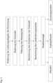
- Fig. 2
- ein Flussdiagramm eines erfindungsgemäßen Verfahrens sowie
- Fig. 3
- zwei Diagramme zur Regelung oder Steuerung eines Treibstoffventils.
- 1
- a schematic representation of a device according to the invention
- 2
- a flowchart of a method according to the invention and
- 3
- two diagrams for the regulation or control of a fuel valve.
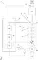
Die in
Der Verbrennungsmotor 2 verfügt über mehrere Zylinder 5. In diesem Ausführungsbeispiel sind konkret acht Zylinder 5 dargestellt, wobei die genaue Anzahl der Zylinder für die vorliegende Erfindung nicht wesentlich ist. Sie kann insbesondere bei einer Zylinderzahl von 8 bis 24 eingesetzt werden.The
Der Verbrennungsmotor 2 verfügt über eine Treibstoffquelle T und ein Treibstoffventil 3. Über dieses werden einer Mischeinrichtung 14 Treibstoff T und Luft L zugeführt. Das entstandene Gemisch wird über eine Drosselklappe 4 Zylindern 5 zugeführt. Die durch Zylinder 5 angetriebene Kurbelwelle 6 treibt ihrerseits einen Rotor des Generators 7 an. Die im Generator 7 bereitgestellte elektrische Energie wird einem oder mehreren Verbrauchern 15 zugeführt.The
An der Kurbelwelle 6 bzw. an der rotierenden Einheit ist ein Sensor 11 positioniert, welcher in diesem Ausführungsbeispiel die Drehzahl N misst. Die Messsignale werden über eine Eingabeschnittstelle 10 einer Kontrolleinheit 9 zugeführt. Das Messsignal wird zunächst mittels eines Filters 8 - in diesem Fall ein Bandpassfilter - gefiltert und einer Berechnungseinheit 12 zugeführt. Die Berechnungseinheit 12 berechnet gemäß der Formel

Falls die Anordnung nicht mit nur einem Massensystem abgebildet werden kann, muss dies mit einer Erweiterung durch die Kombination mehrerer Trägheitsmomente und Winkelgeschwindigkeiten berechnet werden.If the arrangement cannot be represented with only one mass system, this must be calculated with an extension by combining several moments of inertia and angular velocities.
Der Laständerungswert wird einer Regel- und/oder Steuereinheit 13 zugeführt, welche in Abhängigkeit des Laständerungswertes ΔP verschiedene Maßnahmen trifft. Hierzu ist die Regel- und/oder Steuereinheit 13 mit dem Treibstoffventil 3, der Drosselklappe 4 sowie optional einem Bremswiderstand 16 (Lastbank), welcher dem Generator 7 nachgeschaltet ist, verbunden.The load change value is supplied to a regulation and/or
Alternativ oder zusätzlich können andere Aktuatoren zur Regelung oder Steuerung beispielsweise des Ladedrucks zum Einsatz kommen. Beispiele sind das erfindungsgemäße Umblasventil oder ein sogenanntes Wastegate. Ersteres erlaubt einem Teilluftstrom die Umgehung eines Verdichters eines Turboladers. Zweiteres funktioniert analog bei einer Turbine eines Turboladers.Alternatively or additionally, other actuators can be used to regulate or control the charging pressure, for example. examples are the blow-off valve according to the invention or a so-called wastegate. The former allows a partial airflow to bypass a compressor of a turbocharger. The second works analogously with a turbine of a turbocharger.
Bei einer hohen Leistungsreduktion (Lastabwurf) kann das Treibstoffventil sofort geschlossen werden und für eine von der Höher der Leistungsänderung, der Rotationsleistung oder anderen Betriebsparameter (bspw. Drehzahlverlauf) abhängigen Zeit (100 ms bis 5 s) geschlossen bleiben.In the event of a large power reduction (load shedding), the fuel valve can be closed immediately and remain closed for a time (100 ms to 5 s) dependent on the magnitude of the power change, the rotational power or other operating parameters (e.g. speed curve).
Regelorgane zur Beeinflussung des Ladedrucks (In
In
In diesem Beispiel geht man davon aus, dass die Gemischzusammensetzung konstant bleibt, wodurch sich aufgrund der erhöhten Drehzahl und der dadurch erhöhten Gemischmenge eine kurzzeitige Erhöhung der Treibstoffmenge ergeben kann.In this example, it is assumed that the mixture composition remains constant, which can result in a brief increase in the fuel quantity due to the increased speed and the resulting increased mixture quantity.
Durch die relativ schnelle Reaktionszeit liegt der Reaktionszeitpunkt tR relativ nahe am Zeitpunkt tL der Änderung der Lastabgabe (etwa 100 bis 300 ms in diesem Ausführungsbeispiel). Bei einem relativ großen Lastabwurf kann die Treibstoffzufuhr sofort gesperrt werden, wie im unteren Diagramm der Figur erkennbar ist. Die Dauer der Abschaltung liegt in diesem speziellen Beispiel bei etwa 2 s.Due to the relatively fast reaction time, the reaction time tR is relatively close to the time tL of the change in load output (approximately 100 to 300 ms in this exemplary embodiment). In the case of a relatively large load shedding, the fuel supply can be shut off immediately, as can be seen in the lower diagram of the figure. In this specific example, the duration of the switch-off is around 2 s.
Dies ist die Situation beim erfindungsgemäßen Vorgehen, verdeutlicht durch die Kurven B in
Bei einem Vorgehen gemäß dem Stand der Technik (Kurven A in
Wie aus dem Diagramm ersichtlich ist, liegt dieser Grenzwert NL weiter weg vom Sollwert für die Drehzahl als die Drehzahl NR, bei welcher erfindungsgemäß reagiert werden kann. Ein robusterer Betrieb der rotierenden Antriebsmaschine ist also gegeben.As can be seen from the diagram, this limit value NL is further away from the target value for the rotational speed than the rotational speed NR at which a reaction can take place according to the invention. A more robust operation of the rotating drive machine is therefore given.
Claims (12)
- A method for operating an arrangement comprising a rotating drive machine (2), wherein a load change value (ΔP) characteristic of a change of a power output of the arrangement (1) is provided by measuring at least one parameter and/or calculation and- the rotating drive machine (2) is controlled and/or regulated as a function of the load change value (ΔP) and/or- a load of the rotating drive machine (2) is changed as a function of the load change value (ΔP),
such that the change of the power output of the arrangement is substantially compensated,characterised in that within the controlling or regulating as a function of the load change value (ΔP)- a regulating element for the load pressure regulation in the form of a bypass for bypassing a compressor of a turbocharger is controlled or regulated and/or- a fuel valve (3) is closed and/or- the load of the rotating drive machine (2) is changed by a brake resistor (16) which is arranged downstream of an electric generator (7), wherein the generator (7) is driven by the rotating drive machine (2). - The method according to one of claims 1,characterized in that at least one ignition time is changed as a function of the load change value (ΔP).
- The method according to one of claims 1 or 2,characterized in that an ignition of at least one cylinder (5) of the rotating drive machine (2) is suspended as a function of the load change value (ΔP).
- The method according to one of claims 1 to 3,characterized in that a parameter characteristic of a rotation of a shaft (6) driven by the rotating drive machine (2) is measured and the load change value (ΔP) is calculated from the measured parameter.
- The method according to claim 4,characterized in that a rotational speed (N) and/or an angular speed (W) of the driven shaft is measured as the parameter characteristic of the rotation of the shaft (6) driven by the rotating drive machine (2).
- The method according to claim 5,characterized in that the load change value (ΔP) is calculated by means of the formula,

- The method according to one of claims 4 to 6,characterized in that the parameter characteristic of the rotation of the shaft (6) driven by the rotating drive machine (2) is measured at a crankshaft of the rotating drive machine (2).
- The method according to one of claims 4 to 7,characterized in that a measurement signal is filtered from the measuring of the parameter characteristic of the rotation of the shaft (6) driven by the rotating drive machine (2), preferably by means of a low-pass filter (8).
- An arrangement comprising a rotating drive machine (2) and a control unit (9) for controlling and/or regulating the arrangement (1), in particular operating according to any one of claims 1 to 8, wherein the control unit (9) has an input interface (10), by means of which a load change value characteristic of a change of a power output of the arrangement (1) and/or at least one parameter is transmittable to the control unit (9), wherein the load change value (ΔP) is determinable from the at least one parameter, and in that the control unit (9) is designed- to control and/or to regulate the rotating drive machine (2) as a function of the load change value (ΔP) and/or- to change a load of the rotating drive machine (2) as a function of the load change value (ΔP),
such that the change of the power output of the arrangement (1) is substantially compensated,characterized in that the control unit (9) is designed as a function of the load change value (ΔP)- to control or regulate a regulating element for the load pressure regulation in the form of a bypass for bypassing a compressor of a turbocharger and/or- to close a fuel valve (3) and/or- to change the load of the rotating drive machine (2) by a brake resistor (16) which is arranged downstream of an electric generator (7), wherein the generator (7) is driven by the rotating drive machine (2). - The arrangement according to claim 9,characterized in that a sensor (11) connected to the control unit (9) for measuring a parameter characteristic of the rotation of a shaft (6) driven by the rotating drive machine (2) is provided, wherein the control unit (9) is designed to calculate the load change value (ΔP) from a temporal change of the parameter characteristic of the rotation of the driven shaft (6) measured by the sensor (11).
- The arrangement according to claim 9 or 10,characterized in that a generator (7) driven by the rotating drive machine (2) is provided.
- The arrangement according to one of claims 9 to 11,characterized in that the rotating drive machine (2) is a combustion engine, in particular a gas engine.

Applications Claiming Priority (1)
| Application Number | Priority Date | Filing Date | Title |
|---|---|---|---|
| ATA29/2015AAT516817A1 (en) | 2015-01-23 | 2015-01-23 | A method of operating an assembly comprising a rotating work machine |
Publications (2)
| Publication Number | Publication Date |
|---|---|
| EP3048719A1 EP3048719A1 (en) | 2016-07-27 |
| EP3048719B1true EP3048719B1 (en) | 2023-04-19 |
Family
ID=55174532
Family Applications (1)
| Application Number | Title | Priority Date | Filing Date |
|---|---|---|---|
| EP16000107.9AActiveEP3048719B1 (en) | 2015-01-23 | 2016-01-18 | Method for operating an assembly comprising a rotary work machine |
Country Status (7)
| Country | Link |
|---|---|
| US (1) | US10634080B2 (en) |
| EP (1) | EP3048719B1 (en) |
| JP (1) | JP6484185B2 (en) |
| KR (1) | KR101829524B1 (en) |
| CN (1) | CN105822442A (en) |
| AT (1) | AT516817A1 (en) |
| BR (1) | BR102016001325B1 (en) |
Families Citing this family (5)
| Publication number | Priority date | Publication date | Assignee | Title |
|---|---|---|---|---|
| DE102017219785A1 (en)* | 2017-11-07 | 2019-05-09 | Robert Bosch Gmbh | Method for controlling a speed of an internal combustion engine with compensation of a dead time |
| GB2579184B (en) | 2018-11-22 | 2022-02-09 | Dyson Technology Ltd | A method of controlling a brushless permanent magnet motor |
| US11035300B2 (en)* | 2019-03-29 | 2021-06-15 | Rolls-Royce Corporation | Control of a gas turbine driving a generator of an electrical system based on faults detected in the electrical system |
| CN110729925A (en)* | 2019-10-29 | 2020-01-24 | 大力电工襄阳股份有限公司 | Control method for high-voltage synchronous variable-frequency soft start device of blower in steel plant |
| CN112855362B (en)* | 2021-01-15 | 2023-06-16 | 东风越野车有限公司 | Engine speed self-adaptive control method and equipment based on load electricity consumption |
Citations (3)
| Publication number | Priority date | Publication date | Assignee | Title |
|---|---|---|---|---|
| DE10253739B3 (en)* | 2002-11-19 | 2004-05-06 | Mtu Friedrichshafen Gmbh | Idling rev regulation method for IC engine has two filters providing different filtered actual revs signals each compared with required revs signal for providing regulation disparities for rev regulator |
| WO2012135258A2 (en)* | 2011-03-29 | 2012-10-04 | Glacier Bay, Inc. | Generator |
| EP3294610B1 (en)* | 2015-05-11 | 2019-07-17 | ThyssenKrupp Presta AG | Electric power steering system with ripple compensation |
Family Cites Families (47)
| Publication number | Priority date | Publication date | Assignee | Title |
|---|---|---|---|---|
| CH431190A (en) | 1965-02-02 | 1967-02-28 | Sulzer Ag | Method for operating a power plant with a diesel internal combustion engine with liquid fuel and with gas as well as system for carrying out the method |
| JPS59190452A (en)* | 1983-04-12 | 1984-10-29 | Fuji Electric Corp Res & Dev Ltd | Constant rotation control method for diesel engine |
| DE3904480A1 (en) | 1989-02-15 | 1990-08-16 | Bosch Gmbh Robert | VALVE FOR INTERMITTENTLY PUTTING FUEL |
| JP3327696B2 (en)* | 1994-09-08 | 2002-09-24 | 東京瓦斯株式会社 | Operation control method and apparatus for gas engine power generation equipment |
| US5752489A (en) | 1997-02-10 | 1998-05-19 | Cummins Engine Company, Inc. | Integrated fuel measurement and control system for gaseous fuels |
| EP0903469B1 (en)* | 1997-09-22 | 2002-10-30 | Alstom | Method for controlling the power of a turbine plant and device for implementing the method |
| US6112765A (en) | 1998-05-26 | 2000-09-05 | Caterpillar Inc. | Method and apparatus for monitoring operation of a gaseous fuel admission valve |
| US6021755A (en) | 1998-07-23 | 2000-02-08 | Caterpillar Inc. | Method and apparatus for determining a fuel command for a fuel system |
| JP3843408B2 (en)* | 1998-09-16 | 2006-11-08 | 本田技研工業株式会社 | Engine power generation equipment control device |
| US6196189B1 (en) | 1999-06-18 | 2001-03-06 | Caterpillar Inc. | Method and apparatus for controlling the speed of an engine |
| US6606496B1 (en) | 2000-08-25 | 2003-08-12 | Lucent Technologies Inc. | Reverse link other cell interference locator and handoff trigger for wireless network |
| US6371081B1 (en)* | 2000-09-29 | 2002-04-16 | Detroit Diesel Corporation | Inhibit engine speed governor |
| GB2375834B (en) | 2001-02-22 | 2005-06-15 | Cummins Engine Co Inc | Regulating speed of an internal combustion engine |
| US7018254B2 (en)* | 2001-04-11 | 2006-03-28 | Yamaha Marine Kabushiki Kaisha | Fuel injection control for marine engine |
| US7277788B2 (en) | 2002-07-31 | 2007-10-02 | Caterpillar Inc | Charge density control for an internal combustion engine |
| US6728625B2 (en) | 2002-09-27 | 2004-04-27 | Caterpillar Inc | Humidity compensated charge density control for an internal combustion engine |
| CA2442601C (en) | 2003-09-26 | 2005-05-24 | Westport Research Inc. | A fuel injection system and method of operation for a gaseous fuelled engine with liquid pilot fuel ignition |
| GB2412751B (en) | 2004-04-01 | 2006-05-24 | Mtu Friedrichshafen Gmbh | Method for controlling and regulating an IC-engine/generator unit |
| US7117862B2 (en) | 2004-05-06 | 2006-10-10 | Dresser, Inc. | Adaptive engine control |
| DE102004023993B4 (en)* | 2004-05-14 | 2007-04-12 | Mtu Friedrichshafen Gmbh | Method for speed control of an internal combustion engine-generator unit |
| US7082924B1 (en) | 2005-02-04 | 2006-08-01 | Caterpillar Inc | Internal combustion engine speed control |
| US7235892B2 (en) | 2005-09-09 | 2007-06-26 | Cummins, Inc. | Load-based quadratic compensator gain adjustment |
| JP2007120382A (en)* | 2005-10-27 | 2007-05-17 | Toyota Motor Corp | POWER OUTPUT DEVICE, ITS CONTROL METHOD, AND VEHICLE |
| US8307645B2 (en)* | 2005-11-02 | 2012-11-13 | General Electric Company | Apparatus and method for avoidance of turbocharger surge on locomotive diesel engines |
| US7499842B2 (en) | 2005-11-18 | 2009-03-03 | Caterpillar Inc. | Process model based virtual sensor and method |
| JP4599378B2 (en) | 2007-08-30 | 2010-12-15 | 三菱重工業株式会社 | Integrated control method and apparatus for gas engine |
| JP4755155B2 (en) | 2007-08-30 | 2011-08-24 | 三菱重工業株式会社 | Integrated control method and apparatus for gas engine |
| JP4476317B2 (en) | 2007-08-30 | 2010-06-09 | 三菱重工業株式会社 | Integrated control method and apparatus for gas engine |
| DE102008006708B3 (en) | 2008-01-30 | 2009-08-20 | Mtu Friedrichshafen Gmbh | Method for controlling a stationary gas engine |
| FI125798B (en) | 2008-03-03 | 2016-02-29 | Wã Rtsilã Finland Oy | Speed controller for a piston engine |
| US20090261599A1 (en)* | 2008-04-21 | 2009-10-22 | Glacier Bay, Inc. | Power generation system |
| EP2199580A1 (en) | 2008-12-16 | 2010-06-23 | GE Jenbacher GmbH & Co. OHG | Method for operating an internal combustion engine |
| FI121318B (en) | 2008-12-31 | 2010-09-30 | Waertsilae Finland Oy | Method and apparatus for controlling the speed of an internal combustion engine |
| CN102388212B (en) | 2009-05-13 | 2014-03-26 | 瓦锡兰芬兰有限公司 | Engine fuel supply control |
| CN102460950B (en)* | 2009-05-20 | 2015-08-19 | 康明斯发电Ip公司 | Apparatus, system and method for handling electrical load transients, electrical faults and grid failures |
| US8912672B2 (en)* | 2009-05-20 | 2014-12-16 | Cummins Power Generator IP, Inc. | Control of an engine-driven generator to address transients of an electrical power grid connected thereto |
| DE102009023045B4 (en) | 2009-05-28 | 2019-09-12 | Man Energy Solutions Se | Method for operating an Otto internal combustion engine |
| FI20095913A0 (en) | 2009-09-04 | 2009-09-04 | Waertsilae Finland Oy | Control of internal combustion engine speed |
| US8253268B1 (en)* | 2009-10-15 | 2012-08-28 | Airgenesis, LLC | Wind power generation system |
| US8400001B2 (en)* | 2010-01-15 | 2013-03-19 | Kohler Co. | Adaptive control of an electrical generator set based on load magnitude |
| AT509558B1 (en) | 2010-01-19 | 2012-09-15 | Ge Jenbacher Gmbh & Co Ohg | STATIONARY POWER PLANT |
| US20120073550A1 (en) | 2010-09-27 | 2012-03-29 | Radu Oprea | Fuel Metering Device for a Gaseous Fuel Engine |
| WO2012115548A1 (en) | 2011-02-23 | 2012-08-30 | Husqvarna Ab | Control of a/f ratio at cut-out speed |
| FR2979773B1 (en)* | 2011-09-01 | 2013-09-20 | Leroy Somer Moteurs | METHOD FOR CONTROLLING THE OPERATION OF AN ELECTROGEN GROUP |
| JP5944222B2 (en) | 2012-05-01 | 2016-07-05 | ヤンマー株式会社 | Engine speed control device |
| JP2013249037A (en)* | 2012-06-04 | 2013-12-12 | Toyota Motor Corp | Control device for hybrid vehicle |
| FI125034B (en)* | 2013-04-09 | 2015-04-30 | Wärtsilä Finland Oy | Method of operating an electric generator set and electric generator set |
- 2015
- 2015-01-23ATATA29/2015Apatent/AT516817A1/enunknown
- 2016
- 2016-01-18EPEP16000107.9Apatent/EP3048719B1/enactiveActive
- 2016-01-20JPJP2016008388Apatent/JP6484185B2/enactiveActive
- 2016-01-21BRBR102016001325-9Apatent/BR102016001325B1/enactiveIP Right Grant
- 2016-01-21KRKR1020160007708Apatent/KR101829524B1/ennot_activeExpired - Fee Related
- 2016-01-21USUS15/002,783patent/US10634080B2/enactiveActive
- 2016-01-22CNCN201610243825.5Apatent/CN105822442A/enactivePending
Patent Citations (3)
| Publication number | Priority date | Publication date | Assignee | Title |
|---|---|---|---|---|
| DE10253739B3 (en)* | 2002-11-19 | 2004-05-06 | Mtu Friedrichshafen Gmbh | Idling rev regulation method for IC engine has two filters providing different filtered actual revs signals each compared with required revs signal for providing regulation disparities for rev regulator |
| WO2012135258A2 (en)* | 2011-03-29 | 2012-10-04 | Glacier Bay, Inc. | Generator |
| EP3294610B1 (en)* | 2015-05-11 | 2019-07-17 | ThyssenKrupp Presta AG | Electric power steering system with ripple compensation |
Also Published As
| Publication number | Publication date |
|---|---|
| EP3048719A1 (en) | 2016-07-27 |
| JP6484185B2 (en) | 2019-03-13 |
| US10634080B2 (en) | 2020-04-28 |
| BR102016001325A2 (en) | 2016-09-27 |
| JP2016136022A (en) | 2016-07-28 |
| BR102016001325B1 (en) | 2022-07-12 |
| KR101829524B1 (en) | 2018-02-14 |
| US20160215720A1 (en) | 2016-07-28 |
| AT516817A1 (en) | 2016-08-15 |
| KR20160091275A (en) | 2016-08-02 |
| CN105822442A (en) | 2016-08-03 |
Similar Documents
| Publication | Publication Date | Title |
|---|---|---|
| EP3048719B1 (en) | Method for operating an assembly comprising a rotary work machine | |
| EP2038517B1 (en) | Method for operating a gas turbine and gas turbine for carrying out said method | |
| AT509558B1 (en) | STATIONARY POWER PLANT | |
| DE4100692C3 (en) | Speed control device for an internal combustion engine | |
| DE102016106963B4 (en) | Control device for an internal combustion engine | |
| DE102016215610B4 (en) | Control system for an internal combustion engine equipped with a supercharger | |
| EP2312741A2 (en) | Method for early detection and anticipatory control of consumer-end load shedding in an electrical grid, and apparatus for carrying out the method | |
| DE102005040887A1 (en) | Electric turbo compound control system | |
| DE4308198C1 (en) | Torque control via swivel angle or eccentricity in hydrostatic machines with axial and radial piston arrangement | |
| DE102004056894A1 (en) | Method and device for controlling the boost pressure of an internal combustion engine | |
| EP2868903B1 (en) | Method for operating a combustion engine connected with an electric generator | |
| WO2012097389A2 (en) | Method for operating an internal combustion engine having at least two cylinders | |
| EP3061954B1 (en) | Method and device for controlling a drive system of a motor vehicle with a charged combustion engine | |
| WO2020164948A1 (en) | Method for operating a turbocharger | |
| EP2869459B1 (en) | Method for operating a generator connected to an energy supply network | |
| DE102008005121A1 (en) | A method of adjusting a predetermined flow rate in a variable turbine geometry of a turbocharger | |
| AT506182B1 (en) | INTERNAL COMBUSTION ENGINE AND ENGINE CONTROL DEVICE | |
| EP3071799B1 (en) | Determination method and gas turbine | |
| EP3910182A1 (en) | Method for controlling and limiting the speed of a turbocharger | |
| DE102015219459B3 (en) | Method for operating a turbocharger | |
| DE102009000292A1 (en) | Method for producing control or diagnostic variable for turbocharger, involves providing variable geometry to turbocharger in internal combustion engine, where control or diagnostic variable is based on turbine output of turbocharger | |
| DE102015213639B3 (en) | Method for operating an internal combustion engine, control device for an internal combustion engine, and internal combustion engine | |
| WO2024126719A1 (en) | Method for operating an internal combustion engine, control unit for an internal combustion engine, and internal combustion engine | |
| DE102015202691A1 (en) | Method for operating an internal combustion engine and internal combustion engine | |
| DE102019129188A1 (en) | Drive system with a generator control to reduce noise when changing tooth flanks |
Legal Events
| Date | Code | Title | Description |
|---|---|---|---|
| PUAI | Public reference made under article 153(3) epc to a published international application that has entered the european phase | Free format text:ORIGINAL CODE: 0009012 | |
| AK | Designated contracting states | Kind code of ref document:A1 Designated state(s):AL AT BE BG CH CY CZ DE DK EE ES FI FR GB GR HR HU IE IS IT LI LT LU LV MC MK MT NL NO PL PT RO RS SE SI SK SM TR | |
| AX | Request for extension of the european patent | Extension state:BA ME | |
| STAA | Information on the status of an ep patent application or granted ep patent | Free format text:STATUS: REQUEST FOR EXAMINATION WAS MADE | |
| 17P | Request for examination filed | Effective date:20170125 | |
| RBV | Designated contracting states (corrected) | Designated state(s):AL AT BE BG CH CY CZ DE DK EE ES FI FR GB GR HR HU IE IS IT LI LT LU LV MC MK MT NL NO PL PT RO RS SE SI SK SM TR | |
| STAA | Information on the status of an ep patent application or granted ep patent | Free format text:STATUS: EXAMINATION IS IN PROGRESS | |
| 17Q | First examination report despatched | Effective date:20181116 | |
| RAP1 | Party data changed (applicant data changed or rights of an application transferred) | Owner name:INNIO JENBACHER GMBH & CO OG | |
| RIC1 | Information provided on ipc code assigned before grant | Ipc:F02B 53/10 20060101ALN20220802BHEP Ipc:F02B 53/02 20060101ALN20220802BHEP Ipc:F02B 37/18 20060101ALN20220802BHEP Ipc:F02B 37/16 20060101ALN20220802BHEP Ipc:F02D 41/02 20060101ALI20220802BHEP Ipc:F02D 41/14 20060101ALI20220802BHEP Ipc:F02D 41/00 20060101ALI20220802BHEP Ipc:F02M 21/02 20060101ALI20220802BHEP Ipc:F02D 41/10 20060101ALI20220802BHEP Ipc:F02D 19/02 20060101ALI20220802BHEP Ipc:F02D 29/06 20060101ALI20220802BHEP Ipc:H02P 9/04 20060101AFI20220802BHEP | |
| RIC1 | Information provided on ipc code assigned before grant | Ipc:F02B 53/10 20060101ALN20220809BHEP Ipc:F02B 53/02 20060101ALN20220809BHEP Ipc:F02B 37/18 20060101ALN20220809BHEP Ipc:F02B 37/16 20060101ALN20220809BHEP Ipc:F02D 41/02 20060101ALI20220809BHEP Ipc:F02D 41/14 20060101ALI20220809BHEP Ipc:F02D 41/00 20060101ALI20220809BHEP Ipc:F02M 21/02 20060101ALI20220809BHEP Ipc:F02D 41/10 20060101ALI20220809BHEP Ipc:F02D 19/02 20060101ALI20220809BHEP Ipc:F02D 29/06 20060101ALI20220809BHEP Ipc:H02P 9/04 20060101AFI20220809BHEP | |
| GRAP | Despatch of communication of intention to grant a patent | Free format text:ORIGINAL CODE: EPIDOSNIGR1 | |
| STAA | Information on the status of an ep patent application or granted ep patent | Free format text:STATUS: GRANT OF PATENT IS INTENDED | |
| RIC1 | Information provided on ipc code assigned before grant | Ipc:F02B 53/10 20060101ALN20220905BHEP Ipc:F02B 53/02 20060101ALN20220905BHEP Ipc:F02B 37/18 20060101ALN20220905BHEP Ipc:F02B 37/16 20060101ALN20220905BHEP Ipc:F02D 41/02 20060101ALI20220905BHEP Ipc:F02D 41/14 20060101ALI20220905BHEP Ipc:F02D 41/00 20060101ALI20220905BHEP Ipc:F02M 21/02 20060101ALI20220905BHEP Ipc:F02D 41/10 20060101ALI20220905BHEP Ipc:F02D 19/02 20060101ALI20220905BHEP Ipc:F02D 29/06 20060101ALI20220905BHEP Ipc:H02P 9/04 20060101AFI20220905BHEP | |
| INTG | Intention to grant announced | Effective date:20220928 | |
| GRAS | Grant fee paid | Free format text:ORIGINAL CODE: EPIDOSNIGR3 | |
| GRAJ | Information related to disapproval of communication of intention to grant by the applicant or resumption of examination proceedings by the epo deleted | Free format text:ORIGINAL CODE: EPIDOSDIGR1 | |
| GRAL | Information related to payment of fee for publishing/printing deleted | Free format text:ORIGINAL CODE: EPIDOSDIGR3 | |
| STAA | Information on the status of an ep patent application or granted ep patent | Free format text:STATUS: EXAMINATION IS IN PROGRESS | |
| INTC | Intention to grant announced (deleted) | ||
| RIC1 | Information provided on ipc code assigned before grant | Ipc:F02B 53/10 19680901ALN20230104BHEP Ipc:F02B 53/02 19680901ALN20230104BHEP Ipc:F02B 37/18 19950101ALN20230104BHEP Ipc:F02B 37/16 19950101ALN20230104BHEP Ipc:F02D 41/02 19850101ALI20230104BHEP Ipc:F02D 41/14 19850101ALI20230104BHEP Ipc:F02D 41/00 19850101ALI20230104BHEP Ipc:F02M 21/02 19680901ALI20230104BHEP Ipc:F02D 41/10 19850101ALI20230104BHEP Ipc:F02D 19/02 19680901ALI20230104BHEP Ipc:F02D 29/06 19680901ALI20230104BHEP Ipc:H02P 9/04 19680901AFI20230104BHEP | |
| GRAP | Despatch of communication of intention to grant a patent | Free format text:ORIGINAL CODE: EPIDOSNIGR1 | |
| STAA | Information on the status of an ep patent application or granted ep patent | Free format text:STATUS: GRANT OF PATENT IS INTENDED | |
| RIC1 | Information provided on ipc code assigned before grant | Ipc:F02B 53/10 20060101ALN20230207BHEP Ipc:F02B 53/02 20060101ALN20230207BHEP Ipc:F02B 37/18 20060101ALN20230207BHEP Ipc:F02B 37/16 20060101ALN20230207BHEP Ipc:F02D 41/02 20060101ALI20230207BHEP Ipc:F02D 41/14 20060101ALI20230207BHEP Ipc:F02D 41/00 20060101ALI20230207BHEP Ipc:F02M 21/02 20060101ALI20230207BHEP Ipc:F02D 41/10 20060101ALI20230207BHEP Ipc:F02D 19/02 20060101ALI20230207BHEP Ipc:F02D 29/06 20060101ALI20230207BHEP Ipc:H02P 9/04 20060101AFI20230207BHEP | |
| GRAA | (expected) grant | Free format text:ORIGINAL CODE: 0009210 | |
| STAA | Information on the status of an ep patent application or granted ep patent | Free format text:STATUS: THE PATENT HAS BEEN GRANTED | |
| RIC1 | Information provided on ipc code assigned before grant | Ipc:F02B 53/10 20060101ALN20230213BHEP Ipc:F02B 53/02 20060101ALN20230213BHEP Ipc:F02B 37/18 20060101ALN20230213BHEP Ipc:F02B 37/16 20060101ALN20230213BHEP Ipc:F02D 41/02 20060101ALI20230213BHEP Ipc:F02D 41/14 20060101ALI20230213BHEP Ipc:F02D 41/00 20060101ALI20230213BHEP Ipc:F02M 21/02 20060101ALI20230213BHEP Ipc:F02D 41/10 20060101ALI20230213BHEP Ipc:F02D 19/02 20060101ALI20230213BHEP Ipc:F02D 29/06 20060101ALI20230213BHEP Ipc:H02P 9/04 20060101AFI20230213BHEP | |
| INTG | Intention to grant announced | Effective date:20230228 | |
| AK | Designated contracting states | Kind code of ref document:B1 Designated state(s):AL AT BE BG CH CY CZ DE DK EE ES FI FR GB GR HR HU IE IS IT LI LT LU LV MC MK MT NL NO PL PT RO RS SE SI SK SM TR | |
| REG | Reference to a national code | Ref country code:GB Ref legal event code:FG4D Free format text:NOT ENGLISH | |
| REG | Reference to a national code | Ref country code:DE Ref legal event code:R096 Ref document number:502016015698 Country of ref document:DE | |
| REG | Reference to a national code | Ref country code:CH Ref legal event code:EP | |
| REG | Reference to a national code | Ref country code:IE Ref legal event code:FG4D Free format text:LANGUAGE OF EP DOCUMENT: GERMAN | |
| REG | Reference to a national code | Ref country code:AT Ref legal event code:REF Ref document number:1561950 Country of ref document:AT Kind code of ref document:T Effective date:20230515 | |
| P01 | Opt-out of the competence of the unified patent court (upc) registered | Effective date:20230614 | |
| REG | Reference to a national code | Ref country code:LT Ref legal event code:MG9D | |
| REG | Reference to a national code | Ref country code:NL Ref legal event code:MP Effective date:20230419 | |
| PG25 | Lapsed in a contracting state [announced via postgrant information from national office to epo] | Ref country code:NL Free format text:LAPSE BECAUSE OF FAILURE TO SUBMIT A TRANSLATION OF THE DESCRIPTION OR TO PAY THE FEE WITHIN THE PRESCRIBED TIME-LIMIT Effective date:20230419 | |
| PG25 | Lapsed in a contracting state [announced via postgrant information from national office to epo] | Ref country code:SE Free format text:LAPSE BECAUSE OF FAILURE TO SUBMIT A TRANSLATION OF THE DESCRIPTION OR TO PAY THE FEE WITHIN THE PRESCRIBED TIME-LIMIT Effective date:20230419 Ref country code:PT Free format text:LAPSE BECAUSE OF FAILURE TO SUBMIT A TRANSLATION OF THE DESCRIPTION OR TO PAY THE FEE WITHIN THE PRESCRIBED TIME-LIMIT Effective date:20230821 Ref country code:NO Free format text:LAPSE BECAUSE OF FAILURE TO SUBMIT A TRANSLATION OF THE DESCRIPTION OR TO PAY THE FEE WITHIN THE PRESCRIBED TIME-LIMIT Effective date:20230719 Ref country code:ES Free format text:LAPSE BECAUSE OF FAILURE TO SUBMIT A TRANSLATION OF THE DESCRIPTION OR TO PAY THE FEE WITHIN THE PRESCRIBED TIME-LIMIT Effective date:20230419 | |
| PG25 | Lapsed in a contracting state [announced via postgrant information from national office to epo] | Ref country code:RS Free format text:LAPSE BECAUSE OF FAILURE TO SUBMIT A TRANSLATION OF THE DESCRIPTION OR TO PAY THE FEE WITHIN THE PRESCRIBED TIME-LIMIT Effective date:20230419 Ref country code:PL Free format text:LAPSE BECAUSE OF FAILURE TO SUBMIT A TRANSLATION OF THE DESCRIPTION OR TO PAY THE FEE WITHIN THE PRESCRIBED TIME-LIMIT Effective date:20230419 Ref country code:LV Free format text:LAPSE BECAUSE OF FAILURE TO SUBMIT A TRANSLATION OF THE DESCRIPTION OR TO PAY THE FEE WITHIN THE PRESCRIBED TIME-LIMIT Effective date:20230419 Ref country code:LT Free format text:LAPSE BECAUSE OF FAILURE TO SUBMIT A TRANSLATION OF THE DESCRIPTION OR TO PAY THE FEE WITHIN THE PRESCRIBED TIME-LIMIT Effective date:20230419 Ref country code:IS Free format text:LAPSE BECAUSE OF FAILURE TO SUBMIT A TRANSLATION OF THE DESCRIPTION OR TO PAY THE FEE WITHIN THE PRESCRIBED TIME-LIMIT Effective date:20230819 Ref country code:HR Free format text:LAPSE BECAUSE OF FAILURE TO SUBMIT A TRANSLATION OF THE DESCRIPTION OR TO PAY THE FEE WITHIN THE PRESCRIBED TIME-LIMIT Effective date:20230419 Ref country code:GR Free format text:LAPSE BECAUSE OF FAILURE TO SUBMIT A TRANSLATION OF THE DESCRIPTION OR TO PAY THE FEE WITHIN THE PRESCRIBED TIME-LIMIT Effective date:20230720 Ref country code:AL Free format text:LAPSE BECAUSE OF FAILURE TO SUBMIT A TRANSLATION OF THE DESCRIPTION OR TO PAY THE FEE WITHIN THE PRESCRIBED TIME-LIMIT Effective date:20230419 | |
| PG25 | Lapsed in a contracting state [announced via postgrant information from national office to epo] | Ref country code:FI Free format text:LAPSE BECAUSE OF FAILURE TO SUBMIT A TRANSLATION OF THE DESCRIPTION OR TO PAY THE FEE WITHIN THE PRESCRIBED TIME-LIMIT Effective date:20230419 | |
| PG25 | Lapsed in a contracting state [announced via postgrant information from national office to epo] | Ref country code:SK Free format text:LAPSE BECAUSE OF FAILURE TO SUBMIT A TRANSLATION OF THE DESCRIPTION OR TO PAY THE FEE WITHIN THE PRESCRIBED TIME-LIMIT Effective date:20230419 | |
| REG | Reference to a national code | Ref country code:DE Ref legal event code:R097 Ref document number:502016015698 Country of ref document:DE | |
| PG25 | Lapsed in a contracting state [announced via postgrant information from national office to epo] | Ref country code:SM Free format text:LAPSE BECAUSE OF FAILURE TO SUBMIT A TRANSLATION OF THE DESCRIPTION OR TO PAY THE FEE WITHIN THE PRESCRIBED TIME-LIMIT Effective date:20230419 Ref country code:SK Free format text:LAPSE BECAUSE OF FAILURE TO SUBMIT A TRANSLATION OF THE DESCRIPTION OR TO PAY THE FEE WITHIN THE PRESCRIBED TIME-LIMIT Effective date:20230419 Ref country code:RO Free format text:LAPSE BECAUSE OF FAILURE TO SUBMIT A TRANSLATION OF THE DESCRIPTION OR TO PAY THE FEE WITHIN THE PRESCRIBED TIME-LIMIT Effective date:20230419 Ref country code:EE Free format text:LAPSE BECAUSE OF FAILURE TO SUBMIT A TRANSLATION OF THE DESCRIPTION OR TO PAY THE FEE WITHIN THE PRESCRIBED TIME-LIMIT Effective date:20230419 Ref country code:DK Free format text:LAPSE BECAUSE OF FAILURE TO SUBMIT A TRANSLATION OF THE DESCRIPTION OR TO PAY THE FEE WITHIN THE PRESCRIBED TIME-LIMIT Effective date:20230419 Ref country code:CZ Free format text:LAPSE BECAUSE OF FAILURE TO SUBMIT A TRANSLATION OF THE DESCRIPTION OR TO PAY THE FEE WITHIN THE PRESCRIBED TIME-LIMIT Effective date:20230419 | |
| PLBE | No opposition filed within time limit | Free format text:ORIGINAL CODE: 0009261 | |
| STAA | Information on the status of an ep patent application or granted ep patent | Free format text:STATUS: NO OPPOSITION FILED WITHIN TIME LIMIT | |
| 26N | No opposition filed | Effective date:20240122 | |
| PG25 | Lapsed in a contracting state [announced via postgrant information from national office to epo] | Ref country code:SI Free format text:LAPSE BECAUSE OF FAILURE TO SUBMIT A TRANSLATION OF THE DESCRIPTION OR TO PAY THE FEE WITHIN THE PRESCRIBED TIME-LIMIT Effective date:20230419 | |
| PG25 | Lapsed in a contracting state [announced via postgrant information from national office to epo] | Ref country code:SI Free format text:LAPSE BECAUSE OF FAILURE TO SUBMIT A TRANSLATION OF THE DESCRIPTION OR TO PAY THE FEE WITHIN THE PRESCRIBED TIME-LIMIT Effective date:20230419 | |
| PG25 | Lapsed in a contracting state [announced via postgrant information from national office to epo] | Ref country code:MC Free format text:LAPSE BECAUSE OF FAILURE TO SUBMIT A TRANSLATION OF THE DESCRIPTION OR TO PAY THE FEE WITHIN THE PRESCRIBED TIME-LIMIT Effective date:20230419 | |
| PG25 | Lapsed in a contracting state [announced via postgrant information from national office to epo] | Ref country code:MC Free format text:LAPSE BECAUSE OF FAILURE TO SUBMIT A TRANSLATION OF THE DESCRIPTION OR TO PAY THE FEE WITHIN THE PRESCRIBED TIME-LIMIT Effective date:20230419 | |
| REG | Reference to a national code | Ref country code:CH Ref legal event code:PL | |
| PG25 | Lapsed in a contracting state [announced via postgrant information from national office to epo] | Ref country code:LU Free format text:LAPSE BECAUSE OF NON-PAYMENT OF DUE FEES Effective date:20240118 | |
| PG25 | Lapsed in a contracting state [announced via postgrant information from national office to epo] | Ref country code:LU Free format text:LAPSE BECAUSE OF NON-PAYMENT OF DUE FEES Effective date:20240118 | |
| PG25 | Lapsed in a contracting state [announced via postgrant information from national office to epo] | Ref country code:BE Free format text:LAPSE BECAUSE OF NON-PAYMENT OF DUE FEES Effective date:20240131 | |
| PG25 | Lapsed in a contracting state [announced via postgrant information from national office to epo] | Ref country code:CH Free format text:LAPSE BECAUSE OF NON-PAYMENT OF DUE FEES Effective date:20240131 | |
| PG25 | Lapsed in a contracting state [announced via postgrant information from national office to epo] | Ref country code:CH Free format text:LAPSE BECAUSE OF NON-PAYMENT OF DUE FEES Effective date:20240131 Ref country code:BE Free format text:LAPSE BECAUSE OF NON-PAYMENT OF DUE FEES Effective date:20240131 | |
| REG | Reference to a national code | Ref country code:BE Ref legal event code:MM Effective date:20240131 | |
| PG25 | Lapsed in a contracting state [announced via postgrant information from national office to epo] | Ref country code:BG Free format text:LAPSE BECAUSE OF FAILURE TO SUBMIT A TRANSLATION OF THE DESCRIPTION OR TO PAY THE FEE WITHIN THE PRESCRIBED TIME-LIMIT Effective date:20230419 | |
| PG25 | Lapsed in a contracting state [announced via postgrant information from national office to epo] | Ref country code:BG Free format text:LAPSE BECAUSE OF FAILURE TO SUBMIT A TRANSLATION OF THE DESCRIPTION OR TO PAY THE FEE WITHIN THE PRESCRIBED TIME-LIMIT Effective date:20230419 | |
| PGFP | Annual fee paid to national office [announced via postgrant information from national office to epo] | Ref country code:GB Payment date:20241219 Year of fee payment:10 | |
| PGFP | Annual fee paid to national office [announced via postgrant information from national office to epo] | Ref country code:FR Payment date:20241219 Year of fee payment:10 | |
| PG25 | Lapsed in a contracting state [announced via postgrant information from national office to epo] | Ref country code:IE Free format text:LAPSE BECAUSE OF NON-PAYMENT OF DUE FEES Effective date:20240118 | |
| PG25 | Lapsed in a contracting state [announced via postgrant information from national office to epo] | Ref country code:IE Free format text:LAPSE BECAUSE OF NON-PAYMENT OF DUE FEES Effective date:20240118 | |
| REG | Reference to a national code | Ref country code:AT Ref legal event code:MM01 Ref document number:1561950 Country of ref document:AT Kind code of ref document:T Effective date:20240118 | |
| PGFP | Annual fee paid to national office [announced via postgrant information from national office to epo] | Ref country code:DE Payment date:20241218 Year of fee payment:10 | |
| PG25 | Lapsed in a contracting state [announced via postgrant information from national office to epo] | Ref country code:AT Free format text:LAPSE BECAUSE OF NON-PAYMENT OF DUE FEES Effective date:20240118 | |
| PGFP | Annual fee paid to national office [announced via postgrant information from national office to epo] | Ref country code:IT Payment date:20250107 Year of fee payment:10 | |
| PG25 | Lapsed in a contracting state [announced via postgrant information from national office to epo] | Ref country code:CY Free format text:LAPSE BECAUSE OF FAILURE TO SUBMIT A TRANSLATION OF THE DESCRIPTION OR TO PAY THE FEE WITHIN THE PRESCRIBED TIME-LIMIT; INVALID AB INITIO Effective date:20160118 | |
| PG25 | Lapsed in a contracting state [announced via postgrant information from national office to epo] | Ref country code:HU Free format text:LAPSE BECAUSE OF FAILURE TO SUBMIT A TRANSLATION OF THE DESCRIPTION OR TO PAY THE FEE WITHIN THE PRESCRIBED TIME-LIMIT; INVALID AB INITIO Effective date:20160118 |