EP3047186B1 - Seal girding a stick of pipe or a pipeline in the entry or exit ports of a pipe fusion chamber - Google Patents
Seal girding a stick of pipe or a pipeline in the entry or exit ports of a pipe fusion chamberDownload PDFInfo
- Publication number
- EP3047186B1 EP3047186B1EP14771991.8AEP14771991AEP3047186B1EP 3047186 B1EP3047186 B1EP 3047186B1EP 14771991 AEP14771991 AEP 14771991AEP 3047186 B1EP3047186 B1EP 3047186B1
- Authority
- EP
- European Patent Office
- Prior art keywords
- pipe
- seal
- cloth
- opening
- sheets
- Prior art date
- Legal status (The legal status is an assumption and is not a legal conclusion. Google has not performed a legal analysis and makes no representation as to the accuracy of the status listed.)
- Active
Links
- 230000004927fusionEffects0.000titleclaimsdescription37
- 239000004744fabricSubstances0.000claimsdescription66
- 238000001556precipitationMethods0.000claimsdescription9
- 230000003466anti-cipated effectEffects0.000claimsdescription4
- 230000005012migrationEffects0.000claimsdescription3
- 238000013508migrationMethods0.000claimsdescription3
- 238000007499fusion processingMethods0.000description8
- 238000000034methodMethods0.000description4
- 239000000463materialSubstances0.000description3
- 238000007664blowingMethods0.000description2
- 239000000356contaminantSubstances0.000description2
- 230000007613environmental effectEffects0.000description2
- 230000003993interactionEffects0.000description2
- NIXOWILDQLNWCW-UHFFFAOYSA-Nacrylic acid groupChemical groupC(C=C)(=O)ONIXOWILDQLNWCW-UHFFFAOYSA-N0.000description1
- 230000001010compromised effectEffects0.000description1
- 238000010276constructionMethods0.000description1
- 230000003247decreasing effectEffects0.000description1
- 230000001419dependent effectEffects0.000description1
- 238000010586diagramMethods0.000description1
- 230000000694effectsEffects0.000description1
- 239000013536elastomeric materialSubstances0.000description1
- 238000009957hemmingMethods0.000description1
- 238000003780insertionMethods0.000description1
- 230000037431insertionEffects0.000description1
- 238000009413insulationMethods0.000description1
- 230000035515penetrationEffects0.000description1
- 229920000098polyolefinPolymers0.000description1
Images


Classifications
- F—MECHANICAL ENGINEERING; LIGHTING; HEATING; WEAPONS; BLASTING
- F16—ENGINEERING ELEMENTS AND UNITS; GENERAL MEASURES FOR PRODUCING AND MAINTAINING EFFECTIVE FUNCTIONING OF MACHINES OR INSTALLATIONS; THERMAL INSULATION IN GENERAL
- F16L—PIPES; JOINTS OR FITTINGS FOR PIPES; SUPPORTS FOR PIPES, CABLES OR PROTECTIVE TUBING; MEANS FOR THERMAL INSULATION IN GENERAL
- F16L5/00—Devices for use where pipes, cables or protective tubing pass through walls or partitions
- F16L5/02—Sealing
- F16L5/025—Sealing the pipe being movable
- B—PERFORMING OPERATIONS; TRANSPORTING
- B29—WORKING OF PLASTICS; WORKING OF SUBSTANCES IN A PLASTIC STATE IN GENERAL
- B29C—SHAPING OR JOINING OF PLASTICS; SHAPING OF MATERIAL IN A PLASTIC STATE, NOT OTHERWISE PROVIDED FOR; AFTER-TREATMENT OF THE SHAPED PRODUCTS, e.g. REPAIRING
- B29C65/00—Joining or sealing of preformed parts, e.g. welding of plastics materials; Apparatus therefor
- B29C65/02—Joining or sealing of preformed parts, e.g. welding of plastics materials; Apparatus therefor by heating, with or without pressure
- B29C65/18—Joining or sealing of preformed parts, e.g. welding of plastics materials; Apparatus therefor by heating, with or without pressure using heated tools
- B29C65/20—Joining or sealing of preformed parts, e.g. welding of plastics materials; Apparatus therefor by heating, with or without pressure using heated tools with direct contact, e.g. using "mirror"
- B29C65/2092—Joining or sealing of preformed parts, e.g. welding of plastics materials; Apparatus therefor by heating, with or without pressure using heated tools with direct contact, e.g. using "mirror" and involving the use of a facer
- B—PERFORMING OPERATIONS; TRANSPORTING
- B29—WORKING OF PLASTICS; WORKING OF SUBSTANCES IN A PLASTIC STATE IN GENERAL
- B29C—SHAPING OR JOINING OF PLASTICS; SHAPING OF MATERIAL IN A PLASTIC STATE, NOT OTHERWISE PROVIDED FOR; AFTER-TREATMENT OF THE SHAPED PRODUCTS, e.g. REPAIRING
- B29C66/00—General aspects of processes or apparatus for joining preformed parts
- B29C66/001—Joining in special atmospheres
- B29C66/0012—Joining in special atmospheres characterised by the type of environment
- B29C66/0018—Joining in special atmospheres characterised by the type of environment being sterile
- B—PERFORMING OPERATIONS; TRANSPORTING
- B29—WORKING OF PLASTICS; WORKING OF SUBSTANCES IN A PLASTIC STATE IN GENERAL
- B29C—SHAPING OR JOINING OF PLASTICS; SHAPING OF MATERIAL IN A PLASTIC STATE, NOT OTHERWISE PROVIDED FOR; AFTER-TREATMENT OF THE SHAPED PRODUCTS, e.g. REPAIRING
- B29C66/00—General aspects of processes or apparatus for joining preformed parts
- B29C66/01—General aspects dealing with the joint area or with the area to be joined
- B29C66/05—Particular design of joint configurations
- B29C66/10—Particular design of joint configurations particular design of the joint cross-sections
- B29C66/11—Joint cross-sections comprising a single joint-segment, i.e. one of the parts to be joined comprising a single joint-segment in the joint cross-section
- B29C66/114—Single butt joints
- B29C66/1142—Single butt to butt joints
- B—PERFORMING OPERATIONS; TRANSPORTING
- B29—WORKING OF PLASTICS; WORKING OF SUBSTANCES IN A PLASTIC STATE IN GENERAL
- B29C—SHAPING OR JOINING OF PLASTICS; SHAPING OF MATERIAL IN A PLASTIC STATE, NOT OTHERWISE PROVIDED FOR; AFTER-TREATMENT OF THE SHAPED PRODUCTS, e.g. REPAIRING
- B29C66/00—General aspects of processes or apparatus for joining preformed parts
- B29C66/50—General aspects of joining tubular articles; General aspects of joining long products, i.e. bars or profiled elements; General aspects of joining single elements to tubular articles, hollow articles or bars; General aspects of joining several hollow-preforms to form hollow or tubular articles
- B29C66/51—Joining tubular articles, profiled elements or bars; Joining single elements to tubular articles, hollow articles or bars; Joining several hollow-preforms to form hollow or tubular articles
- B29C66/52—Joining tubular articles, bars or profiled elements
- B29C66/522—Joining tubular articles
- B29C66/5221—Joining tubular articles for forming coaxial connections, i.e. the tubular articles to be joined forming a zero angle relative to each other
- B—PERFORMING OPERATIONS; TRANSPORTING
- B29—WORKING OF PLASTICS; WORKING OF SUBSTANCES IN A PLASTIC STATE IN GENERAL
- B29C—SHAPING OR JOINING OF PLASTICS; SHAPING OF MATERIAL IN A PLASTIC STATE, NOT OTHERWISE PROVIDED FOR; AFTER-TREATMENT OF THE SHAPED PRODUCTS, e.g. REPAIRING
- B29C66/00—General aspects of processes or apparatus for joining preformed parts
- B29C66/70—General aspects of processes or apparatus for joining preformed parts characterised by the composition, physical properties or the structure of the material of the parts to be joined; Joining with non-plastics material
- B29C66/71—General aspects of processes or apparatus for joining preformed parts characterised by the composition, physical properties or the structure of the material of the parts to be joined; Joining with non-plastics material characterised by the composition of the plastics material of the parts to be joined
- B—PERFORMING OPERATIONS; TRANSPORTING
- B29—WORKING OF PLASTICS; WORKING OF SUBSTANCES IN A PLASTIC STATE IN GENERAL
- B29C—SHAPING OR JOINING OF PLASTICS; SHAPING OF MATERIAL IN A PLASTIC STATE, NOT OTHERWISE PROVIDED FOR; AFTER-TREATMENT OF THE SHAPED PRODUCTS, e.g. REPAIRING
- B29C66/00—General aspects of processes or apparatus for joining preformed parts
- B29C66/80—General aspects of machine operations or constructions and parts thereof
- B29C66/84—Specific machine types or machines suitable for specific applications
- B29C66/841—Machines or tools adaptable for making articles of different dimensions or shapes or for making joints of different dimensions
- B29C66/8414—Machines or tools adaptable for making articles of different dimensions or shapes or for making joints of different dimensions of different diameter
Definitions
- This inventionrelates generally to fusion of polyolefin pipe and more particularly concerns the integrity of the internal environment of fusion chambers used in "pipelining.”
- Heat fusion joining of sticks of plastic pipe to make a pipelinenormally occurs in the field at the location where the pipeline will be installed, usually outdoors in an open or remote area with no protection from the elements.
- the heat fusion joining processrequires keeping the pipe ends, facer and heater clean and dry because, if precipitation or blowing dirt and debris contaminate the joint, the integrity and strength of the joint are compromised.
- satisfactory fusionis directly and indirectly dependent on the temperature maintained within the fusion chamber.
- a climate-controlled environmentis desirable simply because operator comfort during the fusion process facilitates better performance. It is necessary because in some environmental conditions the fusion process is likely not to produce a satisfactory result and the fusion process should not be performed.
- the fusion machineis kept stationary and a tent or makeshift tent like structure is used to cover the fusion machine and operator.
- the tentmust be large enough to house the fusion machine and its operators and to allow for the heater and facer of the machine to swing into and out of the pipe path.
- the tenthas openings to allow the pipe to enter and exit and to provide an escape for engine exhaust.
- the fusion machineis moved to make each fusion joint, a process known as "pipelining.” It is not practical, however, to move the tent with the machine for each fusion operation.
- the fusion machineis mounted in a climate controlled cab which travels on tracks and also incorporates some pipe handling apparatus.
- the cabhas front and rear openings to allow the pipe sticks to enter and the fused pipe string to exit the cab. These openings have hinged doors that can be closed when no pipe stick or pipeline is in the openings, but during the fusion process the pipe stick and pipeline are in their respective openings. As a result, during the critical fusion time, the doors are left open, leaving a large opening around the pipe.
- DE 10 2008 050 229 Ashows a seal between a perimeter of a pipe passage through a wall and the circumferential surface of pipes of several diameters.
- the pipe-to-cab sealmust minimize heat loss or gain in the climate-controlled air of the cab in cold or hot ambient conditions and also minimize the entry of airborne dirt and other contaminants and blowing rain, snow or sleet into the cab sufficiently to satisfy minimum fused joint standards.
- the sealbe passive so as to open or close without further operator interaction when the pipe stick or pipeline pushes against it on entry or is discharged from it on exit.
- a sealis provided for obstructing migration of outside particulates and precipitation between the perimeter of a pipe passage of a pipe fusion chamber and a pipe passing through the passage.
- the pipemay be a pipe stick or a pipeline of any of various diameters within a selected range of diameters to be passed through a given seal.
- a frame contiguous with a perimeter of the passagedefines an opening which is preferably at least half again as great as a greatest diameter of pipe sticks/pipelines in the range to be passed.
- Sheets of clotheach have an inner edge and an outer edge.
- the sheets of clothtaken together in overlapping serial relationship about a perimeter of the opening, cover the opening with each of the inner edges of the sheets of cloth overlapping an anticipated center axis of a pipe stick/pipeline to be passed through the opening.
- each sheet of clothis preferably at least twice as long as a distance across the opening taken along its respective inner edge in its pipe stick/pipeline center axis overlapping condition.
- the outer edge of each sheet of clothis pleated and fixed to the frame.
- the inner edge of each sheet of clothis gathered on an elastic band.
- Each elastic bandhas a free state length equal to its respective distance across the opening and is elastically stretchable to the length of the cloth's inner edge.
- the ends of each elastic bandare fixed to the frame at the points by which their lengths are determined.
- the pleats and the elastic bandcooperate to allow the inner edges of the sheets of cloth to slide over the face and hug substantially the entire outer circumference of the pipe stick/pipeline.
- the shape of the openingmay be rounded or polygonal and, if polygonal, may be but is not limited to orthogonal.
- the preferred shapeis orthogonal, most preferably square.
- the openinghas sides of length approximately 1.5 times the outer diameter of the largest diameter pipe to be passed through the chamber.
- Four rectangular sheets of clotheach have a length which is approximately twice the length of the sides of the opening and a width which is greater than half the length of the sides of the opening by approximately a quarter of the smallest pipe diameter to be passed through the chamber.
- the pleats in the outer edge of each of the sheets of clothare spaced variably symmetrically distant from the center of the outer edge of the sheet.
- Each of the sheets of clothhas its pleated edge fastened to a different side of the frame.
- the ends of its elastic bandare fixed to opposite sides of the frame with the band substantially parallel to its respective pleated edge and its short edges fully extended on their respective opposite sides of the frame.
- Opposite sheets of clothoverlap each other by approximately half the outer diameter of the smallest diameter pipe of the range to be passed through the chamber.
- the pleat spaces, the elasticity of the elastic bands and the opposite sheet overlapsare coordinated to permit the gathered edges of the sheets to substantially hug the circumference of any pipe within the range of diameters if the pipe is centrally disposed between the gathered edges.
- the present sealis useful for obstructing migration of outside particulates and precipitation into a pipe fusion chamber C in which pipe sticks S are being fused into a pipeline L.
- Pipe sticks S and pipelines Lare hereinafter generically identified as pipes P when the disclosed information is equally applicable to both the sticks S and the pipeline P.
- a fusion chamber Cgenerally houses the pipe fusion machine M and its associated operating equipment and operator (not shown).
- Pipe Pis fed to the fusion machine M in stick form S through an entry passage E in in one wall of the chamber C and exits the fusion machine M in pipeline form L through a pipeline exit passage Eout in an opposite wall of the chamber C.
- different diameters D of pipe Pmay be fused.
- the same fusion machine Mwill be used for a range of diameters D, all of which are accommodated by the same passages E in and E out .
- the smaller the pipe diameter Dthe greater the gap G between the circumference or outer wall W of the pipe P and the passages E in and E out .
- Outside particulates and precipitation, as well as undesirably hot or cold air,can migrate through any gaps G, contaminating and/or causing climatic discomfort in the fusion environment in the chamber C.
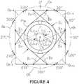
- an end wall F of a pipe P with a central longitudinal axis Ais positioned behind a randomly shaped passage E in a wall of the chamber C.
- Three sheets of cloth X, Y and Zare laid flat and overlapped to cover the entire passage E.
- the sheets of cloth X, Y and Zalso provide a common overlap O around the central longitudinal axis A of the pipe P. While the entire passage E is covered by one or two of the sheets, the common overlap O of the three sheets X, Y and Z is small and preferably, but not necessarily, geometrically symmetrical about the axis A.
- sheets of clothis intended to include any substantially flat and flexible material. Specific environmental conditions or application requirements will impact the selection of the material and its thickness. For example, in extreme cold, acrylic fabric will work well because it retains a high degree of flexibility.
- the sheets of cloth X, Y and Z which were shown flat in Figure 2have been pleated on their outer long edges but are still long enough to cover the passage E. Their inner long edges are gathered on elastic bands B X , B Y and Bz which are stretched across the entire length of their respective inner edges but in a free state are reduced to a length substantially equal to the pleated lengths of the outer edges but sufficient to extend across the passage E.
- the pleating and gathering of the cloths X, Y and Z, as the pipe P pushes against the clothsenable the overlap area O to be opened sufficiently wide for the pipe P to pass between them.
- the center portions of the bands B 1 , B 2 , B 3 and B 4each contact a 60° portion of the pipe circumference, from 60°-120°, 150°-210°, 240°-300° and 330°-30°, totaling 240°.
- the remaining four 30° portions from 30-60°, 120°-150°, 210°-240° and 300°-330°are each contacted by two overlapping band portions B 1 -B 4 , B 3 -B 4 , B 2 -B 3 and B 4 -B 2 , respectively.
- a preferred embodiment of the seal 10is provided for obstructing outside particulates and precipitation from entry into a pipe fusion chamber C along the perimeters of pipe sticks S and a pipeline L at their respective entry and exit passages E in or E out to and from the fusion chamber C.
- the seal 10is identical for both the entry and exit passages E in and E out . It includes a frame 11 with an outer perimeter 13 that is coincident with the entry or exit passage E in or E out in which it is installed.
- the preferred frame inner perimeter 15 showndefines a square opening 17, but perimeters of three or more sides, even if non-symmetrical, can be used. For example, four-sided frames need not necessarily be square or even orthogonal.
- the opening 17has sides 19 of length approximately 1.5 times the outer diameter of the largest diameter pipe stick S or pipeline L to be passed through the frame 11.
- the square opening 17is covered by four substantially rectangular overlapping sheets of cloth 21 b , 21 t , 21 r and 21 l fixed to the frame 11.
- the number of sheets of cloth 21 usedwill correspond to the number of sides 19 of the frame 11 and the shapes of the sheets of cloth 21 will correspond to the shapes defined by the sides 19 of the frame 11 to which they will be attached, though not necessarily symmetrically, as will hereinafter be seen.
- the angular and linear dimensions of the sheets of cloth 21will be empirically determined so that the overlapping sheets of cloth 21 will permit passage of the pipe P while substantially hugging the outer perimeter of pipe P over the entire range of diameters Ds - D L of pipe sticks S or pipelines L to be passed therebetween.
- Substantially huggingas used herein means that only the smallest diameter pipe P DL to be handled by a given seal may have gaps G in the contact of the circumference of the pipe P with the surrounding cloths 21, provided that the air pressure within the fusion chamber C is capable of impeding passage of particulates or precipitation through such gaps G.
- each sheet of cloth 21has a length 23 approximately twice the length of the sides 19 of the frame 11 and a width 25 approximately equal to the largest pipe outer diameter D L to be passed through the frame 11.
- the length 23will vary depending on the elasticity of the cloth 21.
- each sheet of cloth 21has pleats 27 at spaces 29 variably symmetrically distant from a center 31 of its long edge 23.
- the spacing of pleats in Figure 3is at consistent intervals on either side of the axis A.
- the spacingis decreased, preferably and as shown, symmetrically, from the center of the outer edges of the sheets of cloth toward, but short of, the extremities of the outer edges. Therefore, the bulk of available material in the sheets of cloth will be positioned to accommodate the portions of the pipe circumferences which are most problematic.
- the optimum number, spacing and location of the pleats 27 on the outboard edge 23 of the sheets of cloth 21should be located so as to allow the fabric inner gathered edge 23 to expand and allow the pipe P to pass through.
- the pleats 27fix the pleated long edge 23 at a length sufficient for the sheet 21 to overlap opposite sides 19 of the frame 11.
- the unpleated long edges 23 of the sheets of cloth 21 b , 21 t , 21 r and 21 lare hemmed and gathered on elastic bands 37 b , 37 t , 37 r and 37 l , preferably of elastomeric material or surgical tubing, inside of their hems 39.
- the elastic bands 37should be capable of elastically stretching to at least twice their unstretched length.
- each sheet of cloth 21has its pleated edge 23 fastened to a different side 19 of the frame 11 and has the ends 41 and 43 of its elastic band 37 fixed to opposite sides 19 of the frame 11 with the band 37 substantially parallel in an unstretched condition to its respective pleated edge 23.
- the short edges 25 of each sheet of cloth 21are fully extended on their respective opposite sides 19 of the frame 11.
- Opposite ones 21 t and 21 b and 21 l and 21 r of the sheets of cloth 21overlap each other 47 by approximately half of an outer diameter of a smallest diameter pipe P DS to be passed through the frame 11.
- the points 45 at which the elastic bands 37 in the gathered edge hems 39 attach to the frame 11determine the tangency points of the gathered edges 35 with the pipe P and, therefore, the amount of wrap achieved around the pipe P.
- the position of the pipe P in a passage Ealso affects the tangency points. Pipes P way off center would have better wrap in some areas and less in others, but they will be centered on the sheets of cloth 21 during the fusion process because they will be clamped in the fusion machine jaws (not shown). Only the smallest diameter pipe P DS of the range of pipe diameters could pose a problem.
- Internal chamber pressuregenerally allows pressurized and filtered chamber air to flow out through the open ends of the pipe stick S or pipeline L and prevents dirty unheated or uncooled air from flowing into the chamber C through the pipe stick S or pipeline L. This pressure may be sufficient to also handle the gaps G along the pipe circumference. If not, the smallest diameter Ds of the range D S -D L should be increased accordingly. Alternatively, a seal with a greater number of overlapping sheets could be used.
- the seal 10is preferably passive so as to open or close without further interaction when the pipe stick S or pipeline L pushes against the seal 10 on entry or is discharged from the seal 10 on exit. It seals the entry or exit passage E in or E out even when no pipe stick S or pipeline L is in the passage.
- two sets of sheets of cloth 21may be separated by an air gap.
- the outboard-most sheets of cloth 21 l and 21 rare lengthwise vertical so that if any precipitation is collected behind the outboard-most sheets 21 l and 21 r , it will be discharged between the vertical sheets of cloth 21 and away from the fusion chamber C.
- the more inboard sheets of cloth 21 t and 21 bare lengthwise horizontal with the lower horizontal sheet 21 b inward of the upper horizontal sheet 21 t to minimize the likelihood that collected precipitation will be able to pass into the fusion chamber C.
- the spaces 29 between the pleats 27, the length and elasticity of the elastic bands 37 and the amount of overlap 47 of opposite sheets of cloth 21 t and 21 b and 21 1 and 21 rare coordinated to permit the gathered edges 35 of the sheets of cloth 21 to hug entirely or, in the case of the smallest diameter pipe of the applicable range to hug substantially, the circumferential wall W of any pipe stick S or pipeline L having an outer diameter within a range between the largest and smallest outer diameters of pipe stick S or pipeline L to be passed through the seal 10, at least when the hugged pipe stick S or pipeline L is centrally disposed between the gathered edges 35.
- satisfactory coordinated relationships of spacing, elasticity and overlapmay be empirically determined.
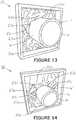
- Figures 12-14show the pipe P after penetration through the seal 10 for pipes having a largest, intermediate and smallest outer diameter, respectively, for example in a range of 20" to 6".
- a satisfactory embodiment of the seal 10has a frame 11 of inner perimeter 15 defining a square opening, perhaps 30" on each side.
- the cloth 21 usedis an elastic fabric.
- Each sheet of cloth 21has a length 23 of approximately 60" and a width 25 of approximately 20".
- the pleated edge 23is approximately 34" long after pleating and is attached to opposite sides 19t and 19 b and 19 l and 19 r of the frame 11.
- the short edges 25 of the cloths 21are approximately 18.5" wide after hemming 39 and are attached to their respective opposite sides 19 t and 19 b or 19 l and 19 r of the frame 11.
- the hemmed edge 23is gathered on a 30" length of surgical tubing 37 capable of elastically stretching to a length of 60" and the ends 41 and 43 of the tubing 37 are secured to the frame 11.
- the overlaps 47 of the gathered edges 35 of opposite sheets of cloth 21 t and 21 b or 21 l and 21 rare 3" wide.
- the 60" gathered edge 23allows each sheet of cloth 21 to "stretch” and curve around any pipe stick S or pipeline L within the 6" to 20" outer diameter range.
- the overlaps 47 of the gathered edges 23 t and 23 b or 23 l and 23 r of the opposing sheet of cloth 21 t and 21 b or 21 l and 21 rhelp to facilitate an air seal between the pipe stick S or the pipeline L and the surrounding gathered edges 23 of cloths 21 when closed on any pipe stick S or pipeline L within the 6" to 20" outer diameter range.
Landscapes
- Engineering & Computer Science (AREA)
- General Engineering & Computer Science (AREA)
- Mechanical Engineering (AREA)
- Lining Or Joining Of Plastics Or The Like (AREA)
- Thermal Insulation (AREA)
Description
- This invention relates generally to fusion of polyolefin pipe and more particularly concerns the integrity of the internal environment of fusion chambers used in "pipelining."
- Heat fusion joining of sticks of plastic pipe to make a pipeline normally occurs in the field at the location where the pipeline will be installed, usually outdoors in an open or remote area with no protection from the elements. The heat fusion joining process requires keeping the pipe ends, facer and heater clean and dry because, if precipitation or blowing dirt and debris contaminate the joint, the integrity and strength of the joint are compromised. Furthermore, satisfactory fusion is directly and indirectly dependent on the temperature maintained within the fusion chamber. A climate-controlled environment is desirable simply because operator comfort during the fusion process facilitates better performance. It is necessary because in some environmental conditions the fusion process is likely not to produce a satisfactory result and the fusion process should not be performed.
- In some known fusion processes, the fusion machine is kept stationary and a tent or makeshift tent like structure is used to cover the fusion machine and operator. The tent must be large enough to house the fusion machine and its operators and to allow for the heater and facer of the machine to swing into and out of the pipe path. The tent has openings to allow the pipe to enter and exit and to provide an escape for engine exhaust.
- In other known fusion processes, the fusion machine is moved to make each fusion joint, a process known as "pipelining." It is not practical, however, to move the tent with the machine for each fusion operation. For "pipelining," the fusion machine is mounted in a climate controlled cab which travels on tracks and also incorporates some pipe handling apparatus. The cab has front and rear openings to allow the pipe sticks to enter and the fused pipe string to exit the cab. These openings have hinged doors that can be closed when no pipe stick or pipeline is in the openings, but during the fusion process the pipe stick and pipeline are in their respective openings. As a result, during the critical fusion time, the doors are left open, leaving a large opening around the pipe. Since the openings are sized for the largest pipe in the pipe range that the machine can fuse, when smaller pipe is being fused the opening around the pipe is larger.
DE 10 2008 050 229 A - Since pipe fusion machines are generally capable of handling pipes within a wide range of pipe outer diameters, it is desirable that the same seal be suitable for use with pipes of any diameter within a given fusion machine's range of diameters. At the same time, however, it is also desirable that the same seal be sufficient to close the entry or exit passage so as to preserve the cabin conditions even when no pipe stick or pipeline is extended through the entry or exit passages.
- In order to keep the number of operators required by and for the fusion machine and process at a minimum, and to minimize the risk of damage to the pipe sticks or pipeline by untimely insertion into the seal, it is also desirable that the seal be passive so as to open or close without further operator interaction when the pipe stick or pipeline pushes against it on entry or is discharged from it on exit.
- The issues above, including adequate climate and contaminant control for both the operator and the process, cost effectiveness of the fusion equipment package and minimization of the operator's tasks in performance of the fusion process, are not fully resolved, if at all, by known stationary and "pipelining" equipment and particularly by known pipeline seals.
- In accordance with the invention, a seal is provided for obstructing migration of outside particulates and precipitation between the perimeter of a pipe passage of a pipe fusion chamber and a pipe passing through the passage. The pipe may be a pipe stick or a pipeline of any of various diameters within a selected range of diameters to be passed through a given seal.
- A frame contiguous with a perimeter of the passage defines an opening which is preferably at least half again as great as a greatest diameter of pipe sticks/pipelines in the range to be passed.
- Sheets of cloth each have an inner edge and an outer edge. The sheets of cloth, taken together in overlapping serial relationship about a perimeter of the opening, cover the opening with each of the inner edges of the sheets of cloth overlapping an anticipated center axis of a pipe stick/pipeline to be passed through the opening.
- The inner edge of each sheet of cloth is preferably at least twice as long as a distance across the opening taken along its respective inner edge in its pipe stick/pipeline center axis overlapping condition. The outer edge of each sheet of cloth is pleated and fixed to the frame. The inner edge of each sheet of cloth is gathered on an elastic band. Each elastic band has a free state length equal to its respective distance across the opening and is elastically stretchable to the length of the cloth's inner edge. The ends of each elastic band are fixed to the frame at the points by which their lengths are determined. When the face of a pipe stick/pipeline to be passed through the seal is aligned on its anticipated center axis with the seal and pushes the overlapping sheets of cloth away from the frame, the pleats and the elastic band cooperate to allow the inner edges of the sheets of cloth to slide over the face and hug substantially the entire outer circumference of the pipe stick/pipeline.
- The shape of the opening may be rounded or polygonal and, if polygonal, may be but is not limited to orthogonal. The preferred shape is orthogonal, most preferably square.
- For a seal with a square opening, the opening has sides of length approximately 1.5 times the outer diameter of the largest diameter pipe to be passed through the chamber. Four rectangular sheets of cloth each have a length which is approximately twice the length of the sides of the opening and a width which is greater than half the length of the sides of the opening by approximately a quarter of the smallest pipe diameter to be passed through the chamber. The pleats in the outer edge of each of the sheets of cloth are spaced variably symmetrically distant from the center of the outer edge of the sheet.
- Each of the sheets of cloth has its pleated edge fastened to a different side of the frame. The ends of its elastic band are fixed to opposite sides of the frame with the band substantially parallel to its respective pleated edge and its short edges fully extended on their respective opposite sides of the frame. Opposite sheets of cloth overlap each other by approximately half the outer diameter of the smallest diameter pipe of the range to be passed through the chamber.
- The pleat spaces, the elasticity of the elastic bands and the opposite sheet overlaps are coordinated to permit the gathered edges of the sheets to substantially hug the circumference of any pipe within the range of diameters if the pipe is centrally disposed between the gathered edges.
- Other objects and advantages of the invention will become apparent upon reading the following detailed description and upon reference to the drawings in which:
Figure1 is a block diagram illustrating a typical pipe fusion chamber;Figure2 is an elevation view illustrating the principles of the seal of the present invention;Figure3 is an elevation view illustrating the principles of the seal of the present invention;Figure4 is an elevation view illustrating the principles of the seal of the present invention ;Figure5 is a perspective assembly view of a seal according to the invention;Figure6 is a perspective view of the seal ofFigure5 fully assembled;Figure7 is a cross-sectional view taken along the line7-7 ofFigure6 ;Figure8 is a cross-sectional view taken along the line8-8 ofFigure6 ;Figure9 is a plan view of a typical sheet of cloth to be used in the seal ofFigure5 ;Figure10 is a plan view of the sheet of cloth ofFigure9 after pleating and gathering for use in the seal ofFigure5 ;Figure11 is a perspective view of the seal ofFigure6 with a large diameter pipe stick pushing against the sheets of the seal;Figure12 is a perspective view of the seal ofFigure6 with the large diameter pipe ofFigure7 pushed between the sheets of cloth to create an opening in the seal;Figure13 is a perspective view of the seal ofFigure6 with an intermediate diameter pipe pushed between the sheets of cloth to create an opening in the seal; andFigure14 is a perspective view of the seal ofFigure6 with a small diameter pipe pushed between the sheets of cloth to create an opening in the seal.- While the invention will be described in connection with a preferred embodiment thereof, it will be understood that it is not intended to limit the invention to that embodiment or to the details of the construction or arrangement of parts illustrated in the accompanying drawings.
- The present seal is useful for obstructing migration of outside particulates and precipitation into a pipe fusion chamber C in which pipe sticks S are being fused into a pipeline L. Pipe sticks S and pipelines L are hereinafter generically identified as pipes P when the disclosed information is equally applicable to both the sticks S and the pipeline P.
- Looking at
Figure1 , a fusion chamber C generally houses the pipe fusion machine M and its associated operating equipment and operator (not shown). Pipe P is fed to the fusion machine M in stick form S through an entry passage Ein in one wall of the chamber C and exits the fusion machine M in pipeline form L through a pipeline exit passage Eout in an opposite wall of the chamber C. From job to job, different diameters D of pipe P may be fused. The same fusion machine M will be used for a range of diameters D, all of which are accommodated by the same passages Ein and Eout. The smaller the pipe diameter D, the greater the gap G between the circumference or outer wall W of the pipe P and the passages Ein and Eout. Outside particulates and precipitation, as well as undesirably hot or cold air, can migrate through any gaps G, contaminating and/or causing climatic discomfort in the fusion environment in the chamber C. - Looking at
Figure2 , an end wall F of a pipe P with a central longitudinal axis A is positioned behind a randomly shaped passage E in a wall of the chamber C. Three sheets of cloth X, Y and Z are laid flat and overlapped to cover the entire passage E. The sheets of cloth X, Y and Z also provide a common overlap O around the central longitudinal axis A of the pipe P. While the entire passage E is covered by one or two of the sheets, the common overlap O of the three sheets X, Y and Z is small and preferably, but not necessarily, geometrically symmetrical about the axis A. - As used herein, "sheets of cloth" is intended to include any substantially flat and flexible material. Specific environmental conditions or application requirements will impact the selection of the material and its thickness. For example, in extreme cold, acrylic fabric will work well because it retains a high degree of flexibility.
- Looking at
Figure3 , the sheets of cloth X, Y and Z which were shown flat inFigure2 have been pleated on their outer long edges but are still long enough to cover the passage E. Their inner long edges are gathered on elastic bands BX, BY and Bz which are stretched across the entire length of their respective inner edges but in a free state are reduced to a length substantially equal to the pleated lengths of the outer edges but sufficient to extend across the passage E. The pleating and gathering of the cloths X, Y and Z, as the pipe P pushes against the cloths, enable the overlap area O to be opened sufficiently wide for the pipe P to pass between them. - Looking at
Figure4 , if a four sheet configuration of cloths were used to seal a passage E around a pipe, the inside long edges of the cloths would be gathered on elastic bands B1, B2, B3 and B4. The same configuration of cloths may be called upon to seal passages E for pipes P over a range of diameters D from a largest diameter DL of pipe PDL to a smallest diameter Ds of pipe PDS. In the example shown, the ends of the bands B1, B2, B3 and B4 are offset to cross at 0°, 90°, 180° and 270° in relation to the center axis A of the pipes PDL and PDS. For the largest diameter pipe PDL, the center portions of the bands B1, B2, B3 and B4 each contact a 60° portion of the pipe circumference, from 60°-120°, 150°-210°, 240°-300° and 330°-30°, totaling 240°. The remaining four 30° portions from 30-60°, 120°-150°, 210°-240° and 300°-330° are each contacted by two overlapping band portions B1-B4, B3-B4, B2-B3 and B4-B2, respectively. But, as seen in the example, for the smallest diameter pipe PDS, the offsets of the ends of the bands B1, B2, B3 and B4 may not provide contact with all 360° of the circumference, leaving small gaps G1-G4, G1-G3, G2-G3 and G2-G4 along the circumference of the smallest diameter pipe PDS. Thus,Figure 4 demonstrates that the smaller the diameter of the smallest pipe PDS, the more problematic might be the achievement of total circumferential pipe hugging. - Looking now at
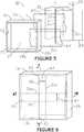
Figures5-8 , a preferred embodiment of theseal 10 is provided for obstructing outside particulates and precipitation from entry into a pipe fusion chamber C along the perimeters of pipe sticks S and a pipeline L at their respective entry and exit passages Ein or Eout to and from the fusion chamber C. - The
seal 10 is identical for both the entry and exit passages Ein and Eout. It includes aframe 11 with anouter perimeter 13 that is coincident with the entry or exit passage Ein or Eout in which it is installed. The preferred frameinner perimeter 15 shown defines asquare opening 17, but perimeters of three or more sides, even if non-symmetrical, can be used. For example, four-sided frames need not necessarily be square or even orthogonal. For thesquare frame 11 shown, theopening 17 hassides 19 of length approximately 1.5 times the outer diameter of the largest diameter pipe stick S or pipeline L to be passed through theframe 11. - As shown, the
square opening 17 is covered by four substantially rectangular overlapping sheets ofcloth frame 11. In most applications, the number of sheets ofcloth 21 used will correspond to the number ofsides 19 of theframe 11 and the shapes of the sheets ofcloth 21 will correspond to the shapes defined by thesides 19 of theframe 11 to which they will be attached, though not necessarily symmetrically, as will hereinafter be seen. The angular and linear dimensions of the sheets ofcloth 21 will be empirically determined so that the overlapping sheets ofcloth 21 will permit passage of the pipe P while substantially hugging the outer perimeter of pipe P over the entire range of diameters Ds - DL of pipe sticks S or pipelines L to be passed therebetween. "Substantially hugging" as used herein means that only the smallest diameter pipe PDL to be handled by a given seal may have gaps G in the contact of the circumference of the pipe P with the surroundingcloths 21, provided that the air pressure within the fusion chamber C is capable of impeding passage of particulates or precipitation through such gaps G. - Looking at
Figure9 , for thesquare frame 11 shown inFigures5-8 , each sheet ofcloth 21 has alength 23 approximately twice the length of thesides 19 of theframe 11 and awidth 25 approximately equal to the largest pipe outer diameter DL to be passed through theframe 11. Thelength 23 will vary depending on the elasticity of thecloth 21. - Looking at
Figure10 , each sheet ofcloth 21 haspleats 27 atspaces 29 variably symmetrically distant from acenter 31 of itslong edge 23. The spacing of pleats inFigure 3 is at consistent intervals on either side of the axis A. InFigure10 , the spacing is decreased, preferably and as shown, symmetrically, from the center of the outer edges of the sheets of cloth toward, but short of, the extremities of the outer edges. Therefore, the bulk of available material in the sheets of cloth will be positioned to accommodate the portions of the pipe circumferences which are most problematic. The optimum number, spacing and location of thepleats 27 on theoutboard edge 23 of the sheets ofcloth 21 should be located so as to allow the fabric inner gatherededge 23 to expand and allow the pipe P to pass through. Thepleats 27 fix the pleatedlong edge 23 at a length sufficient for thesheet 21 to overlapopposite sides 19 of theframe 11. The unpleatedlong edges 23 of the sheets ofcloth elastic bands hems 39. Theelastic bands 37 should be capable of elastically stretching to at least twice their unstretched length. - Returning to
Figures5-8 , each sheet ofcloth 21 has its pleatededge 23 fastened to adifferent side 19 of theframe 11 and has theends elastic band 37 fixed toopposite sides 19 of theframe 11 with theband 37 substantially parallel in an unstretched condition to its respectivepleated edge 23. The short edges 25 of each sheet ofcloth 21 are fully extended on their respectiveopposite sides 19 of theframe 11. Oppositeones cloth 21 overlap each other 47 by approximately half of an outer diameter of a smallest diameter pipe PDS to be passed through theframe 11. - As explained in relation to
Figure4 , thepoints 45 at which theelastic bands 37 in the gatherededge hems 39 attach to theframe 11 determine the tangency points of the gathered edges 35 with the pipe P and, therefore, the amount of wrap achieved around the pipe P. The position of the pipe P in a passage E also affects the tangency points. Pipes P way off center would have better wrap in some areas and less in others, but they will be centered on the sheets ofcloth 21 during the fusion process because they will be clamped in the fusion machine jaws (not shown). Only the smallest diameter pipe PDS of the range of pipe diameters could pose a problem. However, even if theoverlap 47 does not provide complete closure on the circumference of the pipe P, small open areas will not make the seal design impractical if the internal chamber pressure is sufficient. Internal chamber pressure generally allows pressurized and filtered chamber air to flow out through the open ends of the pipe stick S or pipeline L and prevents dirty unheated or uncooled air from flowing into the chamber C through the pipe stick S or pipeline L. This pressure may be sufficient to also handle the gaps G along the pipe circumference. If not, the smallest diameter Ds of the range DS-DL should be increased accordingly. Alternatively, a seal with a greater number of overlapping sheets could be used. - As seen in
Figure11 in which the pipe P is pushing against but not yet through theseal 10, the central portions of the sheets ofcloth frame 11 and, as seen inFigure12 , slide off the face F of the pipe P and onto the circumferential wall W of the pipe P. Greatest expansion is required at approximately the quarter points 49 of the pipe diameter and the need for expansion increases as the diameter increases. The greater the pipe diameter, the closer the quarter points 49 are to the frameinner perimeter 15. Therefore, as best seen inFigure10 , asmaller space 29 betweenpleats 27 is preferred closer to theframe 11 and agreater space 29 betweenpleats 27 is preferred closer to thecenter 31. - The
seal 10 is preferably passive so as to open or close without further interaction when the pipe stick S or pipeline L pushes against theseal 10 on entry or is discharged from theseal 10 on exit. It seals the entry or exit passage Ein or Eout even when no pipe stick S or pipeline L is in the passage. To increase the insulation effect of theseal 10, two sets of sheets ofcloth 21 may be separated by an air gap. - Preferably, the outboard-most sheets of
cloth outboard-most sheets cloth 21 and away from the fusion chamber C. Similarly, the more inboard sheets ofcloth horizontal sheet 21b inward of the upperhorizontal sheet 21t to minimize the likelihood that collected precipitation will be able to pass into the fusion chamber C. - The
spaces 29 between thepleats 27, the length and elasticity of theelastic bands 37 and the amount ofoverlap 47 of opposite sheets ofcloth cloth 21 to hug entirely or, in the case of the smallest diameter pipe of the applicable range to hug substantially, the circumferential wall W of any pipe stick S or pipeline L having an outer diameter within a range between the largest and smallest outer diameters of pipe stick S or pipeline L to be passed through theseal 10, at least when the hugged pipe stick S or pipeline L is centrally disposed between the gathered edges 35. As noted above, satisfactory coordinated relationships of spacing, elasticity and overlap may be empirically determined. Figures12-14 show the pipe P after penetration through theseal 10 for pipes having a largest, intermediate and smallest outer diameter, respectively, for example in a range of 20" to 6". A satisfactory embodiment of theseal 10 has aframe 11 ofinner perimeter 15 defining a square opening, perhaps 30" on each side. Thecloth 21 used is an elastic fabric. Each sheet ofcloth 21 has alength 23 of approximately 60" and awidth 25 of approximately 20". Thepleated edge 23 is approximately 34" long after pleating and is attached toopposite sides frame 11. The short edges 25 of thecloths 21 are approximately 18.5" wide after hemming 39 and are attached to their respectiveopposite sides frame 11. The hemmededge 23 is gathered on a 30" length ofsurgical tubing 37 capable of elastically stretching to a length of 60" and theends tubing 37 are secured to theframe 11. Theoverlaps 47 of the gathered edges 35 of opposite sheets ofcloth edge 23 allows each sheet ofcloth 21 to "stretch" and curve around any pipe stick S or pipeline L within the 6" to 20" outer diameter range. Theoverlaps 47 of the gathered edges 23t and 23b or 23l and 23r of the opposing sheet ofcloth edges 23 ofcloths 21 when closed on any pipe stick S or pipeline L within the 6" to 20" outer diameter range.- Thus, it is apparent that there has been provided, in accordance with the invention, a pipe fusion chamber passage seal that fully satisfies the objects, aims and advantages set forth above.
Claims (13)
- Seal (10) for obstructing migration of particulates and precipitation between a perimeter of a pipe stick/pipeline passage through a wall of a pipe fusion chamber (C) and circumferential surfaces of pipe sticks/pipelines (P) of various diameters within a selected range of diameters to be passed therethrough, the seal (10) comprising:a frame (11) contiguous with a perimeter (13) of the passage (Ein) and defining an opening (17) therein; anda plurality of sheets of cloth (21) each having an inner edge and an outer edge (23), each of said inner edges (23), with said plurality of sheets of cloth (21) taken together in overlapping serial relationship about a perimeter (13) of said opening (17) and covering said opening (17), overlapping an anticipated center axis of a pipe stick/pipeline to be passed through said opening (17);said inner edge (23) of each said sheet of cloth (21) being at least twice as long as a distance across said opening (17) taken along its respective inner edge in its pipe stick/pipeline center axis overlapping condition;said outer edge (23) of each said sheet of cloth (21) being pleated and fixed to said frame (11) and said inner edge (23) of each said sheet of cloth (21) being gathered on an elastic band (37);each said elastic band (37) having a free state length equal to its respective distance across said opening (17) and being elastically stretchable to said length of its respective said inner edge, ends of each of said elastic bands (37) being fixed to said frame (11) at points determining said length thereof;whereby, when a face of a pipe stick/pipeline to be passed through the seal (10) is aligned on said anticipated center axis and pushes said plurality of sheets of cloth (21) away from said frame (11), said pleats (27) and said elastic band (37) cooperate to allow said inner edges (23) of said plurality of sheets of cloth (21) to slide over the face and hug substantially the entire outer circumference of the pipe stick/pipeline.
- An assembly comprising the seal (10) according to claim 1 and the pipe sticks/pipelines (P), said opening in said frame (11) being at least half as great as a greatest diameter of the range.
- A seal (10) according to claim 1, said inner edge (23) of each said sheet of cloth (21) being at least twice as long as a distance across said opening taken along its respective inner edge in its pipe stick/pipeline center axis overlapping condition.
- A seal (10) according to claim 1, said opening being polygonal.
- A seal (10) according to claim 1, said opening being orthogonal.
- A seal (10) according to claim 1, said opening being square.
- An assembly comprising the seal (10) according to claim 6 and the pipe sticks/pipelines (P), said square opening (17) having sides of length approximately 1.5 times an outer diameter of a largest diameter pipe to be passed through the chamber (C).
- An assembly comprising the seal (10) according to claim 6 and the pipe sticks/pipelines (P), said plurality of sheets of cloth (21) comprising four rectangular sheets of cloth having a length approximately twice said length of said opening sides (19) and a width greater than half said length of said opening sides (19) by approximately a quarter of a smallest pipe diameter to be passed through said chamber (C).
- A seal (10) according to claim6, each of said plurality of sheets of cloth (21) having pleats (27) at spaces (29) variably symmetrically distant from a center of a long edge thereof.
- A seal (10) according to claim9, each of said plurality of sheets of cloth (21) having its pleated edge fastened to a different side of said frame (11) and having ends of its elastic band (37) fixed to opposite sides of said frame (11) with said band substantially parallel to its respective pleated edge and its short edges fully extended on their respective opposite sides of said frame (11).
- A seal (10) according to claim10, opposite ones of said plurality of sheets of cloth (21) overlapping each other by approximately half of an outer diameter of a smallest diameter pipe to be passed through the chamber (C).
- A seal (10) according to claim11, said pleat spaces (29), an elasticity of said elastic bands (37) and said opposite sheet overlaps being coordinated to permit said gathered edges of said sheets to hug a circumference of a pipe within a range of said largest and smallest outer diameters centrally disposed between said gathered edges.
- An assembly according to claim 8, wherein the seal (10) is a seal (10) according to any one of claims 9 to 12.
Applications Claiming Priority (2)
| Application Number | Priority Date | Filing Date | Title |
|---|---|---|---|
| US14/029,580US9638355B2 (en) | 2013-09-17 | 2013-09-17 | Seal girding a stick of pipe or a pipeline in the entry or exit ports of a pipe fusion chamber |
| PCT/US2014/052935WO2015041818A1 (en) | 2013-09-17 | 2014-08-27 | Seal girding a stick of pipe or a pipeline in the entry or exit ports of a pipe fusion chamber |
Publications (2)
| Publication Number | Publication Date |
|---|---|
| EP3047186A1 EP3047186A1 (en) | 2016-07-27 |
| EP3047186B1true EP3047186B1 (en) | 2017-10-04 |
Family
ID=51589504
Family Applications (1)
| Application Number | Title | Priority Date | Filing Date |
|---|---|---|---|
| EP14771991.8AActiveEP3047186B1 (en) | 2013-09-17 | 2014-08-27 | Seal girding a stick of pipe or a pipeline in the entry or exit ports of a pipe fusion chamber |
Country Status (4)
| Country | Link |
|---|---|
| US (1) | US9638355B2 (en) |
| EP (1) | EP3047186B1 (en) |
| AU (1) | AU2014321692A1 (en) |
| WO (1) | WO2015041818A1 (en) |
Family Cites Families (10)
| Publication number | Priority date | Publication date | Assignee | Title |
|---|---|---|---|---|
| US3365203A (en)* | 1965-07-26 | 1968-01-23 | Gen Motors Corp | Rolling type diaphragm type seal including oriented reinforcement |
| US4219203A (en)* | 1978-12-29 | 1980-08-26 | Nasa | Thermal barrier pressure seal |
| US5014917A (en)* | 1989-11-27 | 1991-05-14 | The United States Of America As Represented By The Administrator Of The National Aeronautics And Space Administration | High-temperature, flexible, thermal barrier seal |
| EP0551563A1 (en)* | 1992-01-16 | 1993-07-21 | Firma Carl Freudenberg | Shaft seal |
| JPH08187782A (en) | 1995-01-05 | 1996-07-23 | Sekisui Chem Co Ltd | Welding apparatus for plastic pipe |
| JPH10122428A (en) | 1996-10-18 | 1998-05-15 | Mitsubishi Plastics Ind Ltd | Piping construction method |
| DE10333365A1 (en) | 2003-07-23 | 2005-02-24 | Inoex Gmbh | Seal with variable inside diameter |
| GB2460031B (en)* | 2008-05-13 | 2010-08-04 | Rolls Royce Plc | Seal assembly |
| DE102008050229A1 (en) | 2008-10-02 | 2010-04-08 | Extrusion Kempen Gmbh | Device for sealing extruded plastic profile i.e. pipe, in output section of vacuum tank, has nested lamellas overlapped by adjustment, where freely permeable cross section is changeable by overlapping degree |
| DE102011105446B4 (en) | 2011-06-24 | 2013-01-10 | Kraussmaffei Technologies Gmbh | Seal for an extrusion line with variable strand diameter |
- 2013
- 2013-09-17USUS14/029,580patent/US9638355B2/enactiveActive
- 2014
- 2014-08-27EPEP14771991.8Apatent/EP3047186B1/enactiveActive
- 2014-08-27AUAU2014321692Apatent/AU2014321692A1/ennot_activeAbandoned
- 2014-08-27WOPCT/US2014/052935patent/WO2015041818A1/enactiveApplication Filing
Non-Patent Citations (1)
| Title |
|---|
| None* |
Also Published As
| Publication number | Publication date |
|---|---|
| US20150076772A1 (en) | 2015-03-19 |
| WO2015041818A8 (en) | 2015-06-11 |
| AU2014321692A1 (en) | 2016-02-25 |
| WO2015041818A1 (en) | 2015-03-26 |
| EP3047186A1 (en) | 2016-07-27 |
| US9638355B2 (en) | 2017-05-02 |
Similar Documents
| Publication | Publication Date | Title |
|---|---|---|
| US8245464B2 (en) | Flexible dual skin wall and device for tensioning a dual skin flexible wall | |
| CN102667046B (en) | There is the flexible insulated door panel of internal partition | |
| CN102705968A (en) | Cuboidal, in particular cubic, housing for accomodating components of an air-conditioning and/or ventilation system | |
| US10617067B2 (en) | Fastening system and screen installation for a greenhouse, as well as method for attaching the same | |
| EP3177483A1 (en) | Retractable truck bed cover having slat array with flexible joiner members and shielded seams | |
| CN107580521A (en) | Collapsible V-type filter | |
| EP3047186B1 (en) | Seal girding a stick of pipe or a pipeline in the entry or exit ports of a pipe fusion chamber | |
| EP2508690A1 (en) | Flashing for sealing a roof-penetrating building structure to the underroof structure | |
| US20160178104A1 (en) | Pipe assembly comprising a draining system | |
| KR100485009B1 (en) | Filter arrangement | |
| BR102016004591A2 (en) | rotary dust sieve for a vehicle cooling unit, cooling unit and farm vehicle | |
| JP2005504643A (en) | Bellows with molded panels | |
| US4279426A (en) | Seal for space between window openings of a vehicle cab and a camper carried thereby | |
| US5167818A (en) | Reinforced filtering hose | |
| US20140305534A1 (en) | Insulation Jacket | |
| EP1928575B1 (en) | Housing assembly with bagging ring | |
| US9320996B1 (en) | Filter housing utilizing heat shrinkable materials | |
| KR101423914B1 (en) | the system of windbreak for window and frames | |
| KR101459653B1 (en) | ridge of a roof of Glasshouse | |
| JP5600909B2 (en) | Dismantling method for long members with toxic substance-containing members attached | |
| JP2019116788A (en) | Water blocking device | |
| CN101610827A (en) | The device of cleaning industrial filters | |
| EP4115968A1 (en) | An assembly including a filtering element and a cover provided with an inspection hole | |
| US10150074B2 (en) | Air filter element and air filter | |
| AU688857B2 (en) | Sealed ventilation tubing |
Legal Events
| Date | Code | Title | Description |
|---|---|---|---|
| PUAI | Public reference made under article 153(3) epc to a published international application that has entered the european phase | Free format text:ORIGINAL CODE: 0009012 | |
| 17P | Request for examination filed | Effective date:20160209 | |
| AK | Designated contracting states | Kind code of ref document:A1 Designated state(s):AL AT BE BG CH CY CZ DE DK EE ES FI FR GB GR HR HU IE IS IT LI LT LU LV MC MK MT NL NO PL PT RO RS SE SI SK SM TR | |
| AX | Request for extension of the european patent | Extension state:BA ME | |
| DAX | Request for extension of the european patent (deleted) | ||
| GRAP | Despatch of communication of intention to grant a patent | Free format text:ORIGINAL CODE: EPIDOSNIGR1 | |
| INTG | Intention to grant announced | Effective date:20170419 | |
| GRAS | Grant fee paid | Free format text:ORIGINAL CODE: EPIDOSNIGR3 | |
| GRAA | (expected) grant | Free format text:ORIGINAL CODE: 0009210 | |
| AK | Designated contracting states | Kind code of ref document:B1 Designated state(s):AL AT BE BG CH CY CZ DE DK EE ES FI FR GB GR HR HU IE IS IT LI LT LU LV MC MK MT NL NO PL PT RO RS SE SI SK SM TR | |
| REG | Reference to a national code | Ref country code:GB Ref legal event code:FG4D | |
| REG | Reference to a national code | Ref country code:CH Ref legal event code:EP | |
| REG | Reference to a national code | Ref country code:AT Ref legal event code:REF Ref document number:934380 Country of ref document:AT Kind code of ref document:T Effective date:20171015 | |
| REG | Reference to a national code | Ref country code:IE Ref legal event code:FG4D | |
| REG | Reference to a national code | Ref country code:DE Ref legal event code:R096 Ref document number:602014015452 Country of ref document:DE | |
| REG | Reference to a national code | Ref country code:NL Ref legal event code:MP Effective date:20171004 | |
| REG | Reference to a national code | Ref country code:LT Ref legal event code:MG4D | |
| REG | Reference to a national code | Ref country code:AT Ref legal event code:MK05 Ref document number:934380 Country of ref document:AT Kind code of ref document:T Effective date:20171004 | |
| PG25 | Lapsed in a contracting state [announced via postgrant information from national office to epo] | Ref country code:NL Free format text:LAPSE BECAUSE OF FAILURE TO SUBMIT A TRANSLATION OF THE DESCRIPTION OR TO PAY THE FEE WITHIN THE PRESCRIBED TIME-LIMIT Effective date:20171004 | |
| PG25 | Lapsed in a contracting state [announced via postgrant information from national office to epo] | Ref country code:LT Free format text:LAPSE BECAUSE OF FAILURE TO SUBMIT A TRANSLATION OF THE DESCRIPTION OR TO PAY THE FEE WITHIN THE PRESCRIBED TIME-LIMIT Effective date:20171004 Ref country code:SE Free format text:LAPSE BECAUSE OF FAILURE TO SUBMIT A TRANSLATION OF THE DESCRIPTION OR TO PAY THE FEE WITHIN THE PRESCRIBED TIME-LIMIT Effective date:20171004 Ref country code:NO Free format text:LAPSE BECAUSE OF FAILURE TO SUBMIT A TRANSLATION OF THE DESCRIPTION OR TO PAY THE FEE WITHIN THE PRESCRIBED TIME-LIMIT Effective date:20180104 Ref country code:ES Free format text:LAPSE BECAUSE OF FAILURE TO SUBMIT A TRANSLATION OF THE DESCRIPTION OR TO PAY THE FEE WITHIN THE PRESCRIBED TIME-LIMIT Effective date:20171004 Ref country code:FI Free format text:LAPSE BECAUSE OF FAILURE TO SUBMIT A TRANSLATION OF THE DESCRIPTION OR TO PAY THE FEE WITHIN THE PRESCRIBED TIME-LIMIT Effective date:20171004 | |
| PG25 | Lapsed in a contracting state [announced via postgrant information from national office to epo] | Ref country code:RS Free format text:LAPSE BECAUSE OF FAILURE TO SUBMIT A TRANSLATION OF THE DESCRIPTION OR TO PAY THE FEE WITHIN THE PRESCRIBED TIME-LIMIT Effective date:20171004 Ref country code:LV Free format text:LAPSE BECAUSE OF FAILURE TO SUBMIT A TRANSLATION OF THE DESCRIPTION OR TO PAY THE FEE WITHIN THE PRESCRIBED TIME-LIMIT Effective date:20171004 Ref country code:BG Free format text:LAPSE BECAUSE OF FAILURE TO SUBMIT A TRANSLATION OF THE DESCRIPTION OR TO PAY THE FEE WITHIN THE PRESCRIBED TIME-LIMIT Effective date:20180104 Ref country code:HR Free format text:LAPSE BECAUSE OF FAILURE TO SUBMIT A TRANSLATION OF THE DESCRIPTION OR TO PAY THE FEE WITHIN THE PRESCRIBED TIME-LIMIT Effective date:20171004 Ref country code:AT Free format text:LAPSE BECAUSE OF FAILURE TO SUBMIT A TRANSLATION OF THE DESCRIPTION OR TO PAY THE FEE WITHIN THE PRESCRIBED TIME-LIMIT Effective date:20171004 Ref country code:IS Free format text:LAPSE BECAUSE OF FAILURE TO SUBMIT A TRANSLATION OF THE DESCRIPTION OR TO PAY THE FEE WITHIN THE PRESCRIBED TIME-LIMIT Effective date:20180204 Ref country code:GR Free format text:LAPSE BECAUSE OF FAILURE TO SUBMIT A TRANSLATION OF THE DESCRIPTION OR TO PAY THE FEE WITHIN THE PRESCRIBED TIME-LIMIT Effective date:20180105 | |
| REG | Reference to a national code | Ref country code:DE Ref legal event code:R097 Ref document number:602014015452 Country of ref document:DE | |
| PG25 | Lapsed in a contracting state [announced via postgrant information from national office to epo] | Ref country code:CZ Free format text:LAPSE BECAUSE OF FAILURE TO SUBMIT A TRANSLATION OF THE DESCRIPTION OR TO PAY THE FEE WITHIN THE PRESCRIBED TIME-LIMIT Effective date:20171004 Ref country code:DK Free format text:LAPSE BECAUSE OF FAILURE TO SUBMIT A TRANSLATION OF THE DESCRIPTION OR TO PAY THE FEE WITHIN THE PRESCRIBED TIME-LIMIT Effective date:20171004 Ref country code:EE Free format text:LAPSE BECAUSE OF FAILURE TO SUBMIT A TRANSLATION OF THE DESCRIPTION OR TO PAY THE FEE WITHIN THE PRESCRIBED TIME-LIMIT Effective date:20171004 Ref country code:SK Free format text:LAPSE BECAUSE OF FAILURE TO SUBMIT A TRANSLATION OF THE DESCRIPTION OR TO PAY THE FEE WITHIN THE PRESCRIBED TIME-LIMIT Effective date:20171004 | |
| PLBE | No opposition filed within time limit | Free format text:ORIGINAL CODE: 0009261 | |
| STAA | Information on the status of an ep patent application or granted ep patent | Free format text:STATUS: NO OPPOSITION FILED WITHIN TIME LIMIT | |
| PG25 | Lapsed in a contracting state [announced via postgrant information from national office to epo] | Ref country code:RO Free format text:LAPSE BECAUSE OF FAILURE TO SUBMIT A TRANSLATION OF THE DESCRIPTION OR TO PAY THE FEE WITHIN THE PRESCRIBED TIME-LIMIT Effective date:20171004 Ref country code:PL Free format text:LAPSE BECAUSE OF FAILURE TO SUBMIT A TRANSLATION OF THE DESCRIPTION OR TO PAY THE FEE WITHIN THE PRESCRIBED TIME-LIMIT Effective date:20171004 Ref country code:SM Free format text:LAPSE BECAUSE OF FAILURE TO SUBMIT A TRANSLATION OF THE DESCRIPTION OR TO PAY THE FEE WITHIN THE PRESCRIBED TIME-LIMIT Effective date:20171004 | |
| 26N | No opposition filed | Effective date:20180705 | |
| PG25 | Lapsed in a contracting state [announced via postgrant information from national office to epo] | Ref country code:SI Free format text:LAPSE BECAUSE OF FAILURE TO SUBMIT A TRANSLATION OF THE DESCRIPTION OR TO PAY THE FEE WITHIN THE PRESCRIBED TIME-LIMIT Effective date:20171004 | |
| PG25 | Lapsed in a contracting state [announced via postgrant information from national office to epo] | Ref country code:MC Free format text:LAPSE BECAUSE OF FAILURE TO SUBMIT A TRANSLATION OF THE DESCRIPTION OR TO PAY THE FEE WITHIN THE PRESCRIBED TIME-LIMIT Effective date:20171004 | |
| REG | Reference to a national code | Ref country code:CH Ref legal event code:PL | |
| PG25 | Lapsed in a contracting state [announced via postgrant information from national office to epo] | Ref country code:LU Free format text:LAPSE BECAUSE OF NON-PAYMENT OF DUE FEES Effective date:20180827 Ref country code:CH Free format text:LAPSE BECAUSE OF NON-PAYMENT OF DUE FEES Effective date:20180831 Ref country code:LI Free format text:LAPSE BECAUSE OF NON-PAYMENT OF DUE FEES Effective date:20180831 | |
| REG | Reference to a national code | Ref country code:BE Ref legal event code:MM Effective date:20180831 | |
| PG25 | Lapsed in a contracting state [announced via postgrant information from national office to epo] | Ref country code:BE Free format text:LAPSE BECAUSE OF NON-PAYMENT OF DUE FEES Effective date:20180831 Ref country code:FR Free format text:LAPSE BECAUSE OF NON-PAYMENT OF DUE FEES Effective date:20180831 | |
| PG25 | Lapsed in a contracting state [announced via postgrant information from national office to epo] | Ref country code:MT Free format text:LAPSE BECAUSE OF NON-PAYMENT OF DUE FEES Effective date:20180827 | |
| PG25 | Lapsed in a contracting state [announced via postgrant information from national office to epo] | Ref country code:TR Free format text:LAPSE BECAUSE OF FAILURE TO SUBMIT A TRANSLATION OF THE DESCRIPTION OR TO PAY THE FEE WITHIN THE PRESCRIBED TIME-LIMIT Effective date:20171004 | |
| PG25 | Lapsed in a contracting state [announced via postgrant information from national office to epo] | Ref country code:PT Free format text:LAPSE BECAUSE OF FAILURE TO SUBMIT A TRANSLATION OF THE DESCRIPTION OR TO PAY THE FEE WITHIN THE PRESCRIBED TIME-LIMIT Effective date:20171004 | |
| PG25 | Lapsed in a contracting state [announced via postgrant information from national office to epo] | Ref country code:MK Free format text:LAPSE BECAUSE OF NON-PAYMENT OF DUE FEES Effective date:20171004 Ref country code:CY Free format text:LAPSE BECAUSE OF FAILURE TO SUBMIT A TRANSLATION OF THE DESCRIPTION OR TO PAY THE FEE WITHIN THE PRESCRIBED TIME-LIMIT Effective date:20171004 Ref country code:HU Free format text:LAPSE BECAUSE OF FAILURE TO SUBMIT A TRANSLATION OF THE DESCRIPTION OR TO PAY THE FEE WITHIN THE PRESCRIBED TIME-LIMIT; INVALID AB INITIO Effective date:20140827 Ref country code:IE Free format text:LAPSE BECAUSE OF NON-PAYMENT OF DUE FEES Effective date:20180827 | |
| PG25 | Lapsed in a contracting state [announced via postgrant information from national office to epo] | Ref country code:AL Free format text:LAPSE BECAUSE OF FAILURE TO SUBMIT A TRANSLATION OF THE DESCRIPTION OR TO PAY THE FEE WITHIN THE PRESCRIBED TIME-LIMIT Effective date:20171004 | |
| P01 | Opt-out of the competence of the unified patent court (upc) registered | Effective date:20230528 | |
| PGFP | Annual fee paid to national office [announced via postgrant information from national office to epo] | Ref country code:DE Payment date:20240821 Year of fee payment:11 | |
| PGFP | Annual fee paid to national office [announced via postgrant information from national office to epo] | Ref country code:GB Payment date:20240819 Year of fee payment:11 | |
| PGFP | Annual fee paid to national office [announced via postgrant information from national office to epo] | Ref country code:IT Payment date:20240822 Year of fee payment:11 |