EP3042694B1 - Epicardial heart stimulator - Google Patents
Epicardial heart stimulatorDownload PDFInfo
- Publication number
- EP3042694B1 EP3042694B1EP15195554.9AEP15195554AEP3042694B1EP 3042694 B1EP3042694 B1EP 3042694B1EP 15195554 AEP15195554 AEP 15195554AEP 3042694 B1EP3042694 B1EP 3042694B1
- Authority
- EP
- European Patent Office
- Prior art keywords
- stimulation
- electrode
- sensing
- unit
- heart stimulator
- Prior art date
- Legal status (The legal status is an assumption and is not a legal conclusion. Google has not performed a legal analysis and makes no representation as to the accuracy of the status listed.)
- Active
Links
- 230000000638stimulationEffects0.000claimsdescription87
- 230000000747cardiac effectEffects0.000claimsdescription26
- 230000002861ventricularEffects0.000claimsdescription22
- 230000008602contractionEffects0.000claimsdescription14
- 238000002513implantationMethods0.000claimsdescription7
- 238000001514detection methodMethods0.000claimsdescription6
- 210000002837heart atriumAnatomy0.000claimsdescription4
- 230000004044responseEffects0.000claimsdescription3
- 230000001746atrial effectEffects0.000description13
- 210000005242cardiac chamberAnatomy0.000description11
- 210000004165myocardiumAnatomy0.000description7
- 230000000694effectsEffects0.000description6
- 210000005241right ventricleAnatomy0.000description6
- 210000005240left ventricleAnatomy0.000description4
- 230000000004hemodynamic effectEffects0.000description3
- 230000002169extracardiacEffects0.000description2
- 210000005245right atriumAnatomy0.000description2
- 230000004936stimulating effectEffects0.000description2
- 210000001519tissueAnatomy0.000description2
- 239000013598vectorSubstances0.000description2
- 210000002159anterior chamberAnatomy0.000description1
- 238000010586diagramMethods0.000description1
- 238000011156evaluationMethods0.000description1
- 230000006870functionEffects0.000description1
- 210000005003heart tissueAnatomy0.000description1
- 239000007943implantSubstances0.000description1
- 230000010354integrationEffects0.000description1
- 210000003205muscleAnatomy0.000description1
- 230000002107myocardial effectEffects0.000description1
- 230000033764rhythmic processEffects0.000description1
- 230000001360synchronised effectEffects0.000description1
Images


Classifications
- A—HUMAN NECESSITIES
- A61—MEDICAL OR VETERINARY SCIENCE; HYGIENE
- A61N—ELECTROTHERAPY; MAGNETOTHERAPY; RADIATION THERAPY; ULTRASOUND THERAPY
- A61N1/00—Electrotherapy; Circuits therefor
- A61N1/18—Applying electric currents by contact electrodes
- A61N1/32—Applying electric currents by contact electrodes alternating or intermittent currents
- A61N1/36—Applying electric currents by contact electrodes alternating or intermittent currents for stimulation
- A61N1/362—Heart stimulators
- A61N1/365—Heart stimulators controlled by a physiological parameter, e.g. heart potential
- A61N1/368—Heart stimulators controlled by a physiological parameter, e.g. heart potential comprising more than one electrode co-operating with different heart regions
- A—HUMAN NECESSITIES
- A61—MEDICAL OR VETERINARY SCIENCE; HYGIENE
- A61N—ELECTROTHERAPY; MAGNETOTHERAPY; RADIATION THERAPY; ULTRASOUND THERAPY
- A61N1/00—Electrotherapy; Circuits therefor
- A61N1/02—Details
- A61N1/04—Electrodes
- A61N1/05—Electrodes for implantation or insertion into the body, e.g. heart electrode
- A61N1/0587—Epicardial electrode systems; Endocardial electrodes piercing the pericardium
- A—HUMAN NECESSITIES
- A61—MEDICAL OR VETERINARY SCIENCE; HYGIENE
- A61N—ELECTROTHERAPY; MAGNETOTHERAPY; RADIATION THERAPY; ULTRASOUND THERAPY
- A61N1/00—Electrotherapy; Circuits therefor
- A61N1/18—Applying electric currents by contact electrodes
- A61N1/32—Applying electric currents by contact electrodes alternating or intermittent currents
- A61N1/36—Applying electric currents by contact electrodes alternating or intermittent currents for stimulation
- A61N1/372—Arrangements in connection with the implantation of stimulators
- A61N1/37205—Microstimulators, e.g. implantable through a cannula
- A—HUMAN NECESSITIES
- A61—MEDICAL OR VETERINARY SCIENCE; HYGIENE
- A61N—ELECTROTHERAPY; MAGNETOTHERAPY; RADIATION THERAPY; ULTRASOUND THERAPY
- A61N1/00—Electrotherapy; Circuits therefor
- A61N1/18—Applying electric currents by contact electrodes
- A61N1/32—Applying electric currents by contact electrodes alternating or intermittent currents
- A61N1/36—Applying electric currents by contact electrodes alternating or intermittent currents for stimulation
- A61N1/372—Arrangements in connection with the implantation of stimulators
- A61N1/375—Constructional arrangements, e.g. casings
- A61N1/3756—Casings with electrodes thereon, e.g. leadless stimulators
- A—HUMAN NECESSITIES
- A61—MEDICAL OR VETERINARY SCIENCE; HYGIENE
- A61B—DIAGNOSIS; SURGERY; IDENTIFICATION
- A61B5/00—Measuring for diagnostic purposes; Identification of persons
- A61B5/24—Detecting, measuring or recording bioelectric or biomagnetic signals of the body or parts thereof
- A61B5/316—Modalities, i.e. specific diagnostic methods
- A61B5/318—Heart-related electrical modalities, e.g. electrocardiography [ECG]
- A61B5/346—Analysis of electrocardiograms
- A61B5/349—Detecting specific parameters of the electrocardiograph cycle
- A—HUMAN NECESSITIES
- A61—MEDICAL OR VETERINARY SCIENCE; HYGIENE
- A61N—ELECTROTHERAPY; MAGNETOTHERAPY; RADIATION THERAPY; ULTRASOUND THERAPY
- A61N1/00—Electrotherapy; Circuits therefor
- A61N1/18—Applying electric currents by contact electrodes
- A61N1/32—Applying electric currents by contact electrodes alternating or intermittent currents
- A61N1/36—Applying electric currents by contact electrodes alternating or intermittent currents for stimulation
- A61N1/362—Heart stimulators
- A61N1/365—Heart stimulators controlled by a physiological parameter, e.g. heart potential
- A61N1/36507—Heart stimulators controlled by a physiological parameter, e.g. heart potential controlled by gradient or slope of the heart potential
Definitions
- the inventionrelates to an epicardial heart stimulator for stimulating a chamber or antechamber, in particular for stimulating the right or left ventricle of a heart.
- Implantable heart stimulators in the form of pacemakersare known in principle. Such cardiac stimulators are generally connected to electrode lines which have stimulation or defibrillation electrodes in a chamber of a heart or in the immediate vicinity. Epicardial pacemakers do not require such electrode leads, but are implanted on the outside of a heart and stimulate the heart tissue (myocardium) via a stimulation electrode attached to a housing. Such an epicardial pacemaker with a stimulation electrode in the form of a helix is in WO 2013/152259 described.
- a pacemakercan deliver an electrical stimulation pulse to the muscle tissue (myocardium) of a heart chamber in order to produce a stimulated contraction of the heart chamber, provided the stimulation pulse is of sufficient intensity and the heart muscle tissue (myocardium) is not exactly in a refractory phase.
- relatively small-area stimulation electrodesare usually used, since it is sufficient to trigger a stimulated contraction of a heart chamber if only a small part of the myocardium of this heart chamber is initially stimulated.
- Such a stimulated contraction of a ventricleis referred to as a stimulated event in the context of this description.
- Atrial eventcan be a natural atrial event, for example, or - in the case of an atrial pacemaker - also a stimulated atrial event.
- atrial eventcan be natural atrial event, for example, or - in the case of an atrial pacemaker - also a stimulated atrial event.
- a ventriclein particular the right or left ventricle of a heart
- theseare preferably carried out in atrium-synchronous fashion in order to best depict the natural contraction sequence of the heart, in which there is first a contraction of the right atrium and then after an atrioventricular conduction period, there is a contraction of the right ventricle and simultaneously or a little later of the left ventricle.
- the natural contraction of the ventricledoes not occur after some natural contraction of the atrium.
- the natural contraction of the atriumis recorded as an intrinsic atrial event and the right and / or left ventricle is stimulated after a predetermined conduction time.
- Such natural (intrinsic) eventsare detected by sensing, ie measuring, the electrical potentials of the myocardium of the respective heart chamber with the aid of sensing electrodes, which are part of a corresponding electrode lead in conventional heart stimulators.
- the detection of intrinsic events in the ventricleallows, for example, a ventricular cardiac stimulator to be operated in demand mode, in which the delivery of ventricular stimulation pulses is suppressed whenever a natural ventricular event is detected within a respective time window.
- the detection of intrinsic events in the atriumallows, for example, a ventricular cardiac stimulator to deliver ventricular stimulation pulses - as long as they are not suppressed - in atrium-synchronous fashion, i.e. after a predetermined atrioventricular delay time after detection of the respective atrial event.
- the typical stimulation modes that can be implemented with a cardiac stimulatorcan be assumed to be known (VVI, VDD, DDD, etc.), so that they cannot be explained further here.
- Epicardial cardiac stimulatorscan be implanted in 4 different positions, depending on which ventricle or anterior chamber is to be stimulated, i.e. left or right ventricular or left or right atrial.
- the U.S. patent application US 20090088813 A1describes an epicardial pacemaker that has a transmural catheter with electrodes.
- the electrodes arranged on the catheterserve both for the stimulation and for the detection of cardiac signals.
- the U.S. patent application US 20070179540 A1describes a cardiac rhythm sensor which has a screw by means of which it can be attached to the epicardium. A tip and a ring electrode are used to record heart signals, which can be transmitted to another implant via a telemetry unit.
- the object of the inventionis to develop further stimulation modes for epicardial cardiac stimulators.
- an epicardial heart stimulatorwhich has a housing and electrical components arranged in this housing, including a stimulation unit and a stimulation control unit, such as on the housing at least one stimulation electrode.
- the stimulation electrodeis connected to the stimulation unit, which in turn is connected to the stimulation control unit.
- the stimulation unitis designed to provide electrical energy for a stimulation pulse and to emit a stimulation pulse via the stimulation electrode in response to a corresponding trigger signal from the stimulation control unit.
- a sensing electrode for sensing electrical potentialsis provided on the housing and is electrically connected to a sensing unit in the housing.
- the sensing unitis in turn connected to the stimulation control unit connected and the stimulation control unit is configured in such a way that, in a corresponding operating mode, it controls the emission of a respective trigger signal as a function of an output signal of the sensing unit.
- the inventorshave recognized that the sensing of intrinsic signals in an epicardial cardiac stimulator is largely local and thus only the activity in a chamber can be detected. Since epicardial heart stimulators only have local electrodes (poles) attached to their housing, the sensing electrodes are always adjacent to the heart chamber or antechamber that is to be stimulated. With such an epicardial cardiac stimulator, usually only one sensing in the chamber is possible, which is adjacent to the epicardial cardiac pacemaker, so that such a cardiac pacemaker can also implement single-chamber operating modes such as AAI or VVI.
- the detection of the activityis also possible in a distant chamber, that is to say in a chamber other than the chamber to which the epicardial pacemaker is adjacent.
- a ventricular epicardial pacemakersensing atrial events and thus atrial synchronous stimulation is also necessary e.g. in VDD mode with a single epicardial ventricular cardiac stimulator possible without the need for a second implanted device.
- the integration of one or more sensing electrodesis thus provided in the housing of the epicardial cardiac stimulator, the electrodes preferably taking up a maximum spatial distance so that far-field signals from distant chambers can be perceived and used for the timing.
- the sensing unitis preferably connected to the sensing electrode and the stimulation electrode or a second sensing electrode and the stimulation control unit is designed to evaluate the output signal of the sensing unit with regard to those signal features which indicate a contraction of a distant antechamber and / or heart chamber.
- the output signal from the sensing unitis typical a femoral electrocardiogram so that the sensing unit is a far field sensing unit.
- a plurality of sensing electrodesare provided on the housing for sensing electrical potentials.
- the sensing unitcomprises a switch with which one or two of the sensing electrodes can be electrically connected to the other components of the sensing unit designed to record an electrocardiogram
- An indifferent electrode poleis arranged on the housing in the immediate vicinity of the stimulation electrode and, together with it, forms a stimulation electrode pair.
- the indifferent electrode poleis formed by a ring electrode which at least partially surrounds the stimulation electrode.
- the indifferent electrode polecan also be formed by another electrode in the vicinity of the stimulation electrode which has a larger surface than the stimulation electrode.
- the stimulation electrodeis a helix electrode.
- a helix electrodeallows the epicardial heart stimulator to be attached by screwing the helix electrode into the myocardium like a corkscrew.
- the epicardial cardiac stimulatoris preferably designed as a ventricular pacemaker in such a way that it can be operated in atrium-synchronous manner at least in a VDD operating mode.
- the epicardial cardiac stimulatoris preferably a demand pacemaker, which is designed to detect intrinsic events of a respective chamber to be stimulated and to suppress delivery of a stimulation pulse if an intrinsic activity of the respective cardiac chamber is detected within a corresponding time window.
- the epicardial heart stimulatoris a rate-adaptive pacemaker, which can adapt a stimulation rate to a hemodynamic requirement of a particular patient.
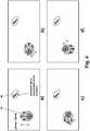
- Fig. 1shows a view of an epicardial pacemaker 10 on its side facing the heart after implantation.
- a helix electrode 12is arranged as a different stimulation electrode pole and around it a ring electrode 14 as an indifferent electrode pole.
- the helix electrode 12 and the ring electrode 14serve to stimulate the heart chamber or antechamber which is arranged adjacent to the epicardial pacemaker 10 after implantation.
- three sensing electrodes 16are arranged.
- Fig. 2It can be seen that the three sensing electrodes 16 are connected to a pacemaker logic and signal processing 20 via a programmable switch 18. Helix electrode 12 and ring electrode 14 are also connected to pacemaker logic and signal processing 20.
- the helix electrode 12forms the ventricular stimulation electrode and the ring electrode 14 the corresponding counter electrode.
- the helix electrode 12, together with one of the sensing electrodes 16,is used to detect electrical potential profiles that represent a far-field electrocardiogram, as is shown, for example, in FIG Fig. 6 is shown.
- the programmable switch 18makes it possible to connect each sensing electrode 16 to a corresponding far-field sensing unit of the pacemaker logic and signal processing 20, which together with the helix electrode 12 delivers the best signal.
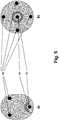
- pacemaker logic and signal processing 20are shown schematically.
- the pacemaker logic and signal processing 20are located in a housing 22, on the surface of which the stimulation electrode 12, the ring electrode 14 and the three sensing electrodes 16 are arranged.
- the stimulation electrode 12 and the ring electrode 14are each connected both to a stimulation unit 24 and to a sensing unit 26.
- the stimulation unit 24is a right ventricular stimulation unit and the sensing unit 26 is a right ventricular sensing unit.
- the stimulation unit 24is designed to provide the energy for a stimulation pulse and to deliver it to adjacent tissue via the stimulation electrode 12 in response to a trigger signal.
- the stimulation unit 24is connected to a stimulation control unit 28, which is a corresponding trigger signal generated.
- the sensing unit 26can detect local cardiac events via the stimulation electrode 12 and the ring electrode 14, that is to say in particular those cardiac events which are to be assigned to the chamber to which the epicardial cardiac stimulator 10 is arranged.
- the sensing unit 26thus detects right ventricular events and outputs a corresponding output signal to the stimulation control unit 28 when a respective ventricular event is sensed. This allows the stimulation control unit 28 to trigger stimulation pulses only when necessary, namely when the sensing unit 26 has not detected an intrinsic ventricular event.
- the three sensing electrodes 16are connected to a far field sensing unit 30, which is connected to the stimulation electrode 12 via a further input.
- the far-field sensing unit 30is designed to evaluate the potential difference between one of the three sensing electrodes 16 and the stimulation electrode in the sense of a far-field electrocardiogram.
- the far-field sensing unit 30has an in Fig. 3 not shown, but in Fig. 2 indicated programmable switch 18, which makes it possible to output and / or use one of the three sensing electrodes 16 for sensing.
- a single sensing electrode or two or more than three sensing electrodescan be provided. If only a single sensing electrode 16 is provided, the programmable switch 18 can be omitted.
- the far-field sensing unit 30supplies the stimulation control unit 28 with an output signal, as exemplarily shown in FIG Fig. 6 is depicted, and which contains signal features which, for example, signal an atrial activity. This is in Fig. 6 highlighted accordingly.
- the stimulation control unit 28is thus also able to detect, for example, atrial events if the epicardial heart stimulator 10 is used as a ventricular pacemaker and is arranged accordingly, for example adjacent to the right ventricle.
- the epicardial cardiac stimulator depictedis thus possible, for example, for atrium-synchronous stimulation of the right ventricle as needed.
- the stimulation control unitcan be connected to a storage unit 30, which is used, for example, to store control signals or also to store signal profiles that the epicardial cardiac stimulator 12 has recorded.
- the epicardial cardiac pacemaker 12also has a telemetry unit 34 which is connected to the memory 32.
- the stimulation control unitcan also be connected to an activity sensor 36 of the type known per se, so that a rate-adaptive pacemaker results.
- the activity sensor 36can be a sensor known per se that delivers an output signal that depends on the hemodynamic requirement of a patient.
- the stimulation control unit 28is also connected to a timer unit 38.
- Figures 4c) to 4dexplain, by way of example, that the three stimulation electrodes 16 of the epicardial stimulator 10 allow a sensing vector to be clamped with one of the sensing electrodes 16 and the stimulation electrode 12 allowed.
- Fig. 5explains that in addition to the example in the Figures 1 to 4 Arrangement of electrodes shown, alternative electrode numbers and arrangements can also be provided. So shows Fig. 5a that the indifferent electrode pole does not necessarily have to be formed by a ring electrode, but can also be formed, for example, only by half a ring or a different, somewhat larger area. In addition, instead of three sensing electrodes 16, only two sensing electrodes can be provided; please refer Fig. 5a ,
- a central arrangement of the different electrode pole(helix electrode 12) can also be provided, with an indifferent ring electrode 14 arranged around it.
- four sensing electrodes 16are arranged.
- sensingcan also take place via two of the four sensing electrodes.
- the far field sensing unitis not connected to one sensing electrode and the different stimulation electrode pole, but to two sensing electrodes.
- FIG 6an extracardiac electrocardiogram is shown as an example, as it can be recorded with an epicardial cardiac stimulator 10.
- a signal section 42which represents an atrial event, is marked as an example.
Landscapes
- Health & Medical Sciences (AREA)
- Life Sciences & Earth Sciences (AREA)
- Heart & Thoracic Surgery (AREA)
- Animal Behavior & Ethology (AREA)
- Radiology & Medical Imaging (AREA)
- Nuclear Medicine, Radiotherapy & Molecular Imaging (AREA)
- Biomedical Technology (AREA)
- General Health & Medical Sciences (AREA)
- Public Health (AREA)
- Veterinary Medicine (AREA)
- Engineering & Computer Science (AREA)
- Cardiology (AREA)
- Biophysics (AREA)
- Physiology (AREA)
- Electrotherapy Devices (AREA)
Description
Translated fromGermanDie Erfindung betrifft einen epikardialen Herzstimulator zur Stimulation einer Kammer oder Vorkammer, insbesondere zur Stimulation des rechten oder des linken Ventrikels eines Herzens.The invention relates to an epicardial heart stimulator for stimulating a chamber or antechamber, in particular for stimulating the right or left ventricle of a heart.
Implantierbare Herzstimulatoren in Form von Herzschrittmachern sind grundsätzlich bekannt. Solche Herzstimulatoren sind in der Regel an Elektrodenleitungen angeschlossen, die in einer Kammer eines Herzens oder in unmittelbarer Nähe Stimulations- oder Defibrillationselektroden besitzen. Epikardiale Herzschrittmacher benötigen solche Elektrodenleitungen nicht, sondern werden an der Außenseite eines Herzens implantiert und stimulieren das Herzgewebe (Myokard) über eine an einem Gehäuse angebrachte Stimulationselektrode. Ein solcher epikardialer Herzschrittmacher mit einer Stimulationselektrode in Form einer Helix ist in
Über die Stimulationselektrode kann ein Herzschrittmacher einen elektrischen Stimulationsimpuls an das Muskelgewebe (Myokard) einer Herzkammer abgeben, um so eine stimulierte Kontraktion der Herzkammer hervorzurufen, sofern der Stimulationsimpuls eine ausreichende Intensität besitzt und das Herzmuskelgewebe (Myokard) sich nicht gerade in einer refraktären Phase befindet. Um auf diese Weise eine stimulierte Kontraktion einer Herzkammer auszulösen, werden üblicher Weise relativ kleinflächige Stimulationselektroden verwendet, da es zum Auslösen einer stimulierten Kontraktion einer Herzkammer ausreicht, wenn nur ein kleiner Teil des Myokards dieser Herzkammer anfänglich stimuliert wird. Eine derartige stimulierte Kontraktion einer Herzkammer wird im Rahmen dieser Beschreibung als stimuliertes Ereignis bezeichnet. Kommt es zu einer natürlichen Kontraktion der Herzkammer, wird dies im Rahmen dieser Beschreibung als Eigenaktion oder als intrinsisches Ereignis bezeichnet. Eine Kontraktion beispielsweise des rechten Atriums eines Herzens wird als atriales Ereignis bezeichnet, welches beispielsweise ein natürliches atriales Ereignis sein kann, oder - im Falle eines atrialen Herzschrittmachers - auch ein stimuliertes atriales Ereignis. Im gleichen Sinne können natürliche (intrinsische) und stimulierte linksventrikuläre und rechtsventrikuläre Ereignisse unterschieden werden.Via the stimulation electrode, a pacemaker can deliver an electrical stimulation pulse to the muscle tissue (myocardium) of a heart chamber in order to produce a stimulated contraction of the heart chamber, provided the stimulation pulse is of sufficient intensity and the heart muscle tissue (myocardium) is not exactly in a refractory phase. In order to trigger a stimulated contraction of a heart chamber in this way, relatively small-area stimulation electrodes are usually used, since it is sufficient to trigger a stimulated contraction of a heart chamber if only a small part of the myocardium of this heart chamber is initially stimulated. Such a stimulated contraction of a ventricle is referred to as a stimulated event in the context of this description. If there is a natural contraction of the heart chamber, this is referred to as self-action or an intrinsic event in the context of this description. A contraction For example, the right atrium of a heart is referred to as an atrial event, which can be a natural atrial event, for example, or - in the case of an atrial pacemaker - also a stimulated atrial event. In the same sense, a distinction can be made between natural (intrinsic) and stimulated left ventricular and right ventricular events.
In Bezug auf die Stimulation einer Herzkammer, insbesondere des rechten oder des linken Ventrikels eines Herzens, ist weiter anzumerken, dass diese vorzugsweise atriumsynchron erfolgen, um möglichst gut die natürliche Kontraktionssequenz des Herzens abzubilden, bei der es zunächst zu einer Kontraktion des rechten Atriums und anschließend nach einer atrioventrikulären Überleitungszeit zu einer Kontraktion des rechten Ventrikels und gleichzeitig oder wenig später des linken Ventrikels kommt. Unter bestimmten Umständen unterbleibt bei einigen Patienten die natürliche Kontraktion des Ventrikels im Nachgang einer natürlichen Kontraktion des Atriums. In typischen Zweikammerschrittmachern wird daher die natürliche Kontraktion des Atriums als intrinsisches atriales Ereignis erfasst und nach einer vorgegebenen Überleitungszeit der rechte und/oder der linke Ventrikel stimuliert.With regard to the stimulation of a ventricle, in particular the right or left ventricle of a heart, it should also be noted that these are preferably carried out in atrium-synchronous fashion in order to best depict the natural contraction sequence of the heart, in which there is first a contraction of the right atrium and then after an atrioventricular conduction period, there is a contraction of the right ventricle and simultaneously or a little later of the left ventricle. In some patients, the natural contraction of the ventricle does not occur after some natural contraction of the atrium. In typical two-chamber pacemakers, the natural contraction of the atrium is recorded as an intrinsic atrial event and the right and / or left ventricle is stimulated after a predetermined conduction time.
Das Erfassen solcher natürlichen (intrinsischen) Ereignisse erfolgt durch Abfühlen, also Messen, der elektrischen Potenziale des Myokards der jeweiligen Herzkammer mit Hilfe von Sensingelektroden, die bei herkömmlichen Herzstimulatoren Teil einer entsprechenden Elektrodenleitung sind.Such natural (intrinsic) events are detected by sensing, ie measuring, the electrical potentials of the myocardium of the respective heart chamber with the aid of sensing electrodes, which are part of a corresponding electrode lead in conventional heart stimulators.
Das Erfassen von intrinsischen Ereignissen im Ventrikel erlaubt es beispielsweise einen ventrikulären Herzstimulator im Demand-Modus zu betreiben, in dem die Abgabe von ventrikulären Stimulationsimpulsen immer dann unterdrückt wird wenn innerhalb eines jeweiligen Zeitfensters ein natürliches ventrikuläres Ereignis erfasst wird. Das Erfassen von intrinsischen Ereignissen im Atrium erlaubt es beispielsweise einem ventrikulären Herzstimulator ventrikuläre Stimulationsimpulse - solange sie nicht unterdrückt werden - atriumsynchron, also nach einer vorgegebenen atrioventrikulären Verzögerungszeit nach Erfassen des jeweiligen atrialen Ereignisses abzugeben.The detection of intrinsic events in the ventricle allows, for example, a ventricular cardiac stimulator to be operated in demand mode, in which the delivery of ventricular stimulation pulses is suppressed whenever a natural ventricular event is detected within a respective time window. The detection of intrinsic events in the atrium allows, for example, a ventricular cardiac stimulator to deliver ventricular stimulation pulses - as long as they are not suppressed - in atrium-synchronous fashion, i.e. after a predetermined atrioventricular delay time after detection of the respective atrial event.
Die typischen Stimulationsmodi, die sich mit einem Herzstimulator verwirklichen lassen, können als bekannt vorausgesetzt werden (VVI, VDD, DDD usw.), so dass sie hier nicht weiter zu erläutern sind.The typical stimulation modes that can be implemented with a cardiac stimulator can be assumed to be known (VVI, VDD, DDD, etc.), so that they cannot be explained further here.
Epikardiale Herzstimulatoren können an 4 verschiedenen Positionen implantiert werden, je nachdem, welche Herzkammer oder Vorkammer stimuliert werden soll, also links- oder rechtsventrikulär oder links- oder rechtsatrial.Epicardial cardiac stimulators can be implanted in 4 different positions, depending on which ventricle or anterior chamber is to be stimulated, i.e. left or right ventricular or left or right atrial.
Die US-Patentanmeldung
Die US-Patentanmeldung
Der Erfindung liegt die Aufgabe zugrunde, möglichst weitere Stimulationsmodi für epikardiale Herzstimulatoren zu erschließen.The object of the invention is to develop further stimulation modes for epicardial cardiac stimulators.
Erfindungsgemäß wird diese Aufgabe durch einen epikardialen Herzstimulator nach Anspruch 1 gelöst, der ein Gehäuse und in diesem Gehäuse angeordnete elektrische Komponenten einschließlich einer Stimulationseinheit und einer Stimulationssteuereinheit aufweist, so wie an dem Gehäuse wenigstens eine Stimulationselektrode. Die Stimulationselektrode ist mit der Stimulationseinheit verbunden und diese wiederum mit der Stimulationssteuereinheit. Die Stimulationseinheit ist ausgebildet, elektrische Energie für einen Stimulationsimpuls zur Verfügung zu stellen und auf ein entsprechendes Auslösesignal der Stimulationssteuereinheit hin einen Stimulationsimpuls über die Stimulationselektrode abzugeben. Außerdem ist an dem Gehäuse eine Sensingelektrode zum Abfühlen elektrischer Potentiale vorgesehen, die mit einer Sensingeinheit in dem Gehäuse elektrisch verbunden ist. Die Sensingeinheit ist ihrerseits wiederum mit der Stimulationssteuereinheit verbunden und die Stimulationssteuereinheit ist so konfiguriert, dass sie in einem entsprechenden Betriebsmodus das Abgeben eines jeweiligen Auslösesignals in Abhängigkeit eines Ausgangssignals der Sensingeinheit steuert.According to the invention, this object is achieved by an epicardial heart stimulator according to
Die Erfinder haben erkannt, dass das Sensing intrinsischer Signale bei einem epikardialen Herzstimulator weitgehend lokal ist und damit nur die Erkennung der Aktivität in einer Kammer möglich ist. Da epikardiale Herzstimulatoren nur lokale, an ihrem Gehäuse angebrachte Elektroden (-pole) aufweisen, sind auch die Sensingelektroden immer der Herzkammer oder Vorkammer benachbart, die stimuliert werden soll. Mit einem derartigen epikardialen Herzstimulator ist üblicherweise nur ein Sensing in der Kammer möglich, der der epikardiale Herzschrittmacher benachbart ist, so dass ein derartiger Herzschrittmacher auch solche Einkammer-Betriebsmodi realisieren kann wie AAI oder VVI.The inventors have recognized that the sensing of intrinsic signals in an epicardial cardiac stimulator is largely local and thus only the activity in a chamber can be detected. Since epicardial heart stimulators only have local electrodes (poles) attached to their housing, the sensing electrodes are always adjacent to the heart chamber or antechamber that is to be stimulated. With such an epicardial cardiac stimulator, usually only one sensing in the chamber is possible, which is adjacent to the epicardial cardiac pacemaker, so that such a cardiac pacemaker can also implement single-chamber operating modes such as AAI or VVI.
Mit der vorliegenden Erfindung wird die Erkennung der Aktivität auch in einer entfernten Kammer, also einer anderen als derjenigen Kammer, der der epikardiale Herzschrittmacher benachbart ist, möglich. Bei einem ventrikulären epikardialen Herzschrittmacher ist also auch ein Sensing atrialer Ereignisse und dadurch eine vorhofsynchrone Stimulation z.B. im VDD Modus mit einem einzelnen epikardial platzierten ventrikulären Herzstimulator möglich, ohne dass hierzu ein zweites implantiertes Gerät erforderlich ist.With the present invention, the detection of the activity is also possible in a distant chamber, that is to say in a chamber other than the chamber to which the epicardial pacemaker is adjacent. With a ventricular epicardial pacemaker, sensing atrial events and thus atrial synchronous stimulation is also necessary e.g. in VDD mode with a single epicardial ventricular cardiac stimulator possible without the need for a second implanted device.
Erfindungsgemäß ist somit die Integration einer oder mehrerer Sensing-Elektroden im Gehäuse des epikardialen Herzstimulators vorgesehen, wobei die Elektroden vorzugsweise einen räumlich maximalen Abstand einnehmen, damit Fernfeld-Signale aus entfernten Kammern wahrgenommen und für das Timing verwendet werden können.According to the invention, the integration of one or more sensing electrodes is thus provided in the housing of the epicardial cardiac stimulator, the electrodes preferably taking up a maximum spatial distance so that far-field signals from distant chambers can be perceived and used for the timing.
Vorzugsweise ist die Sensingeinheit mit der Sensingelektrode und der Stimulationselektrode oder einer zweiten Sensingelektrode verbunden und die Stimulationssteuereinheit ausgebildet, das Ausgangssignal der Sensingeinheit hinsichtlich solcher Signalmerkmale auszuwerten, die eine Kontraktion einer entfernten Vorkammer und/oder Herzkammer anzeigen. Das Ausgangssignal der Sensingeinheit ist typischerweise ein Femfeldelektrokardiogramm, so dass die Sensingeinheit eine Fernfeldsensingeinheit ist.The sensing unit is preferably connected to the sensing electrode and the stimulation electrode or a second sensing electrode and the stimulation control unit is designed to evaluate the output signal of the sensing unit with regard to those signal features which indicate a contraction of a distant antechamber and / or heart chamber. The output signal from the sensing unit is typical a femoral electrocardiogram so that the sensing unit is a far field sensing unit.
Gemäß einer weiteren bevorzugten Ausführungsvariante sind an dem Gehäuse mehrere Sensingelektroden zum Abfühlen elektrischer Potentiale vorgesehen. Die Sensingeinheit umfasst einen Schalter, mit dem eine oder zwei der Sensingelektroden mit den übrigen zum Aufnehmen eines Elektrokardiogramm ausgebildeten Komponenten der Sensingeinheit umschaltbar elektrisch zu verbinden sindAccording to a further preferred embodiment variant, a plurality of sensing electrodes are provided on the housing for sensing electrical potentials. The sensing unit comprises a switch with which one or two of the sensing electrodes can be electrically connected to the other components of the sensing unit designed to record an electrocardiogram
An dem Gehäuse ist ein indifferenter Elektrodenpol in unmittelbarer Nähe der Stimulationselektrode angeordnet und bildet mit dieser zusammen ein Stimulationselektrodenpaar. Der indifferente Elektrodenpol ist von einer Ringelektrode gebildet, die die Stimulationselektrode wenigstens teilweise umschließt. Alternativ kann der indifferente Elektrodenpol auch von einer anderen gegenüber der Stimulationselektrode großflächigeren Elektrode in der Nähe der Stimulationselektrode gebildet sein.An indifferent electrode pole is arranged on the housing in the immediate vicinity of the stimulation electrode and, together with it, forms a stimulation electrode pair. The indifferent electrode pole is formed by a ring electrode which at least partially surrounds the stimulation electrode. Alternatively, the indifferent electrode pole can also be formed by another electrode in the vicinity of the stimulation electrode which has a larger surface than the stimulation electrode.
Die Stimulationselektrode ist eine Helixelektrode. Eine Helixelektrode erlaubt eine Befestigung des epikardialen Herzstimulators indem die Helixelektrode ähnlich eines Korkenziehers in das Myokard eingeschraubt wird.The stimulation electrode is a helix electrode. A helix electrode allows the epicardial heart stimulator to be attached by screwing the helix electrode into the myocardium like a corkscrew.
Vorzugsweise ist der epikardiale Herzstimulator als ventrikulärer Herzschrittmacher so ausgebildet, dass er wenigstens in einem VDD-Betriebsmodus atriumsynchron zu betreiben ist.The epicardial cardiac stimulator is preferably designed as a ventricular pacemaker in such a way that it can be operated in atrium-synchronous manner at least in a VDD operating mode.
Außerdem ist der epikardiale Herzstimulator vorzugsweise ein Demand-Schrittmacher, der ausgebildet ist, intrinsische Ereignisse einer jeweiligen zu stimulierenden Kammer zu erfassen und eine Abgabe eines Stimulationsimpulses zu unterdrücken, falls innerhalb eines entsprechenden Zeitfensters eine intrinsische Aktivität der jeweiligen Herzkammer erfasst wird.In addition, the epicardial cardiac stimulator is preferably a demand pacemaker, which is designed to detect intrinsic events of a respective chamber to be stimulated and to suppress delivery of a stimulation pulse if an intrinsic activity of the respective cardiac chamber is detected within a corresponding time window.
Gemäß einer weiteren bevorzugten Ausführungsvariante ist der epikardiale Herzstimulator ein ratenadaptiver Schrittmacher, der eine Stimulationsrate an einen hämodynamischen Bedarf eines jeweiligen Patienten anpassen kann.According to a further preferred embodiment variant, the epicardial heart stimulator is a rate-adaptive pacemaker, which can adapt a stimulation rate to a hemodynamic requirement of a particular patient.
Die Erfindung soll nun anhand von Ausführungsbeispielen mit Bezug auf die Figuren erläutert werden. Von den Figuren zeigen:
- Fig. 1:
- Eine Ansicht eines epikardialen Herzschrittmachers auf dessen nach Implantation dem Herzen zugewandter Seite;
- Fig. 2:
- eine Skizze zur Erläuterung der Verschaltung der Elektroden des epikardialen Herzschrittmachers aus
Fig. 1 mit einer Schrittmacher logik und Signalverarbeitung; - Fig. 3:
- ein schematisches Blockdiagramm der wesentlichen Komponenten der Schrittmacherlogik und Signalverarbeitung;
- Fig. 4a bis 4d:
- verschiedene mögliche Orientierungen des epikardialen Herzschrittmachers aus
Fig. 1 nach Implantation; - Fig. 5a und 5b:
- zwei alternative Ausführungsvarianten eines epikardialen Herzschrittmachers; und
- Fig. 6:
- von einem epikardialen Herzschrittmacher aufgenommene extrakardiale Signale.
- Fig. 1:
- A view of an epicardial pacemaker on its side facing the heart after implantation;
- Fig. 2:
- a sketch to explain the connection of the electrodes of the epicardial pacemaker
Fig. 1 with pacemaker logic and signal processing; - Fig. 3:
- a schematic block diagram of the essential components of the pacemaker logic and signal processing;
- 4a to 4d:
- different possible orientations of the epicardial pacemaker
Fig. 1 after implantation; - 5a and 5b:
- two alternative versions of an epicardial pacemaker; and
- Fig. 6:
- extracardiac signals recorded by an epicardial pacemaker.
Wie
Bei Verwendung des epikardialen Herzstimulators 10 als ventrikulären Herzschrittmacher bildet die Helixelektrode 12 die ventrikuläre Stimulationselektrode und die Ringelektrode 14 die entsprechende Gegenelektrode.When using the epicardial
Außerdem dient die Helixelektrode 12 zusammen mit einer der Sensingelektroden 16 zum Erfassen elektrischer Potentialverläufe, die ein Fernfeld-Elektrokardiogramm repräsentieren, so wie es beispielsweise in
In
Die Stimulationselektrode 12 und die Ringelektrode 14 sind jeweils sowohl mit einer Stimulationseinheit 24 als auch mit einer Sensingeinheit 26 verbunden. Bei Verwendung des epikardialen Herzstimulators als rechtsventrikulären Herzschrittmacher ist die Stimulationseinheit 24 eine rechtsventrikuläre Stimulationseinheit und die Sensingeinheit 26 eine rechtsventrikuläre Sensingeinheit. Die Stimulationseinheit 24 ist ausgebildet, die Energie für einen Stimulationsimpuls bereitzustellen und auf ein Auslösesignal hin über die Stimulationselektrode 12 an anliegendes Gewebe abzugeben. Hierzu ist die Stimulationseinheit 24 mit einer Stimulationssteuereinheit 28 verbunden, die ein entsprechendes Auslösesignal generiert. Die Sensingeinheit 26 kann über die Stimulationselektrode 12 und die Ringelektrode 14 lokale Herzereignisse erfassen, das heißt insbesondere solche Herzereignisse, die der Kammer zuzuordnen sind, der benachbart der epikardiale Herzstimulator 10 angeordnet ist. Im Falle eines ventrikulären Herzschrittmachers erfasst die Sensingeinheit 26 somit rechtsventrikuläre Ereignisse und gibt beim Erfassen eines jeweiligen ventrikulären Ereignisses ein entsprechendes Ausgangssignal an die Stimulationssteuereinheit 28 aus. Dies erlaubt es der Stimulationssteuereinheit 28, Stimulationsimpulse nur im Bedarfsfall auszulösen, nämlich dann, wenn die Sensingeinheit 26 kein intrinsisches ventrikuläres Ereignis erfasst hat.The
Die drei Sensingelektroden 16 sind mit einer Fernfeld-Sensingeinheit 30 verbunden, die über einen weiteren Eingang mit der Stimulationselektrode 12 verbunden ist. Die Fernfeld-Sensingeinheit 30 ist ausgebildet, die Potentialdifferenz zwischen einer der drei Sensingelektroden 16 und der Stimulationselektrode im Sinne eines Fernfeld-Elektrokardiogramms auszuwerten. Dazu weist die Fernfeld-Sensingeinheit 30 einen in
Mit dem in
In
In
In
- 1010
- HerzschrittmacherPacemaker
- 1212
- Stift- oder HelixelektrodePen or helix electrode
- 1414
- Ringelektrodering electrode
- 1616
- SensingelektrodeSensing electrode
- 1818
- Schalterswitch
- 2020
- Signalverarbeitungsignal processing
- 2222
- Gehäusecasing
- 2424
- Stimulationseinheitstimulation unit
- 2626
- SensingeinheitSensing unit
- 2828
- StimulationssteuereinheitStimulation control unit
- 3030
- Fernfeld-SensingeinheitFar-field sensing unit
- 3232
- SpeicherStorage
- 3434
- Telemetrieeinheittelemetry unit
- 3636
- Aktivitätssensoractivity sensor
- 3838
- ZeitgebereinheitTimer unit
- 4040
- elektrisch aktive myokardiale Zellenelectrically active myocardial cells
- 4242
- atriales Ereignis im fernfeld-ElektrokardiogrammAtrial event in the far-field electrocardiogram
Claims (7)
- An epicardial heart stimulator (10), comprising a housing (20) and electrical components arranged in this housing (20), which comprise a stimulation unit (24) and a stimulation control unit (28) connected to the stimulation unit (24), and further comprising, on the housing (20), at least one stimulation electrode (12), which is connected to the stimulation unit (24), the stimulation unit (24) being designed to provide electrical energy for a stimulation pulse and to emit a stimulation pulse via the stimulation electrode in response to a corresponding trigger signal of the stimulation control unit (28), and a sensing electrode (16), which is electrically connected to a sensing unit (30) in the housing (20), being provided on the housing (20) for sensing electrical potentials, the sensing unit (30) in turn being connected to the stimulation control unit (28), and the stimulation control unit (28) being configured, in an appropriate operating mode, to control the emission of a respective trigger signal as a function of an output signal of the sensing unit (30),
characterized in that
the stimulation electrode (12), the indifferent electrode pole (14) and the sensing electrodes (16) are arranged on the side facing the heart after implantation of the epicardial heart stimulator, the stimulation electrode (12) being designed as a helix electrode for attachment of the epicardial heart stimulator, the indifferent electrode pole (14) being formed by a ring electrode surrounding the stimulation electrode, and 4 sensing electrodes (16) for detecting electrical potential profiles representing a far-field electrocardiogram being arranged around the stimulation electrode (12), outside the annular indifferent electrode pole (14), the detection of electrical potential profiles representing a far-field electrocardiogram selectively taking place either by way of 2 of the 4 sensing electrodes (16) or by way of the stimulation electrode (12) and one of the sensing electrodes (16). - The epicardial heart stimulator according to claim 1,characterized in that the sensing unit (30) is connected to the sensing electrode (16) and the stimulation electrode (12) or a second sensing electrode (16), and the stimulation control unit (28) is designed to evaluate the output signal of the sensing unit (30) with respect to signal features that indicate a contraction of an atrium and/or a ventricle lying furthest away.
- The epicardial heart stimulator according to claim 1 or 2,characterized in that a plurality of sensing electrodes (16) for sensing electrical potentials are provided on the housing (20), and the sensing unit (30) comprises a switch by which one or two of the sensing electrodes (16) are to be electrically connected, so as to be switchable, to the remaining components of the sensing unit (30) that are designed to record an electrocardiogram.
- The epicardial heart stimulator according to at least one of claims 1 to 3,characterized in that an indifferent electrode pole (14) is arranged on the housing (20) in the immediate vicinity of the stimulation electrode (12).
- The epicardial heart stimulator according to at least one of claims 1 to 4,characterized in that the epicardial heart stimulator (10) is designed as a ventricular cardiac pacemaker so as to be operated atrial-synchronously at least in a VDD operating mode.
- The epicardial heart stimulator according to at least one of claims 1 to 5,characterized in that the epicardial heart stimulator (10) is a demand pacemaker.
- The epicardial heart stimulator according to at least one of claims 1 to 6,characterized in that the epicardial heart stimulator (10) is a rate-adaptive pacemaker.
Applications Claiming Priority (1)
| Application Number | Priority Date | Filing Date | Title |
|---|---|---|---|
| US201562100099P | 2015-01-06 | 2015-01-06 |
Publications (2)
| Publication Number | Publication Date |
|---|---|
| EP3042694A1 EP3042694A1 (en) | 2016-07-13 |
| EP3042694B1true EP3042694B1 (en) | 2020-01-08 |
Family
ID=54608432
Family Applications (1)
| Application Number | Title | Priority Date | Filing Date |
|---|---|---|---|
| EP15195554.9AActiveEP3042694B1 (en) | 2015-01-06 | 2015-11-20 | Epicardial heart stimulator |
Country Status (2)
| Country | Link |
|---|---|
| US (1) | US9956415B2 (en) |
| EP (1) | EP3042694B1 (en) |
Families Citing this family (1)
| Publication number | Priority date | Publication date | Assignee | Title |
|---|---|---|---|---|
| CN117159926A (en)* | 2022-05-27 | 2023-12-05 | 合源医疗器械(上海)有限公司 | Implantable heart failure treatment device |
Family Cites Families (9)
| Publication number | Priority date | Publication date | Assignee | Title |
|---|---|---|---|---|
| US20090088813A1 (en)* | 2004-03-12 | 2009-04-02 | Brockway Brian P | Cardiac Rhythm Management Device |
| US7890159B2 (en)* | 2004-09-30 | 2011-02-15 | Cardiac Pacemakers, Inc. | Cardiac activation sequence monitoring and tracking |
| US7650186B2 (en)* | 2004-10-20 | 2010-01-19 | Boston Scientific Scimed, Inc. | Leadless cardiac stimulation systems |
| EP1948296B2 (en)* | 2005-10-14 | 2017-10-11 | Pacesetter, Inc. | Leadless cardiac pacemaker and system |
| US8050759B2 (en)* | 2006-01-31 | 2011-11-01 | Medtronic, Inc. | Subcutaneous ICD with separate cardiac rhythm sensor |
| US20090275999A1 (en)* | 2008-04-30 | 2009-11-05 | Burnes John E | Extra-cardiac implantable device with fusion pacing capability |
| US9101281B2 (en)* | 2011-09-27 | 2015-08-11 | Medtronic, Inc. | IMD stability monitor |
| EP2833964B1 (en) | 2012-04-05 | 2021-06-23 | Childrens Hospital Los Angeles | Minimally invasive epicardial pacemaker |
| WO2014031752A1 (en)* | 2012-08-21 | 2014-02-27 | Nanostim, Inc. | X-ray identification for active implantable medical device |
- 2015
- 2015-11-20EPEP15195554.9Apatent/EP3042694B1/enactiveActive
- 2015-12-10USUS14/965,153patent/US9956415B2/enactiveActive
Non-Patent Citations (1)
| Title |
|---|
| None* |
Also Published As
| Publication number | Publication date |
|---|---|
| US20160193467A1 (en) | 2016-07-07 |
| US9956415B2 (en) | 2018-05-01 |
| EP3042694A1 (en) | 2016-07-13 |
Similar Documents
| Publication | Publication Date | Title |
|---|---|---|
| EP2060299B1 (en) | Biventricular heart stimulator | |
| EP1714670B1 (en) | Pacemaker | |
| DE69919983T2 (en) | SYSTEM FOR INTRODUCING HEART CHAMBER FLOURS USING NAHFELD WAVE SCANNING | |
| DE60221186T2 (en) | Dual chamber pacemaker system with a dynamically adjusted interpulse delay | |
| EP2433565B1 (en) | Implantable medical device | |
| DE60303244T2 (en) | An implantable cardiac stimulating device and system comprising this device | |
| EP2540341B1 (en) | Cardiac stimulator for delivery of cardiac contractility modulation therapy | |
| EP1774988B1 (en) | Implantable cardiac vector determination device | |
| EP2628503B1 (en) | Cardiac stimulator for cardiac contractility modulation | |
| EP3025759A1 (en) | Mri capable active implantable device | |
| EP2540342A1 (en) | Cardiac stimulator for delivery of cardiac contractility modulation therapy | |
| EP3042694B1 (en) | Epicardial heart stimulator | |
| DE102007057227B4 (en) | Cardiac stimulation arrangement | |
| EP1569715A1 (en) | Biventricular cardiac pacemaker for cardiac resynchronisation therapy | |
| EP2111894B1 (en) | Heart stimulator with stimulation success control | |
| EP3103513B1 (en) | Rate adaptive intra- or epicardial heart stimulator and activity sensor | |
| EP3025757A1 (en) | Mri capable active implantable device and mri sensor | |
| EP2422843B1 (en) | Implantable electronic therapy device | |
| EP2308558B1 (en) | Biventricular cardiac stimulator | |
| DE102008020123A1 (en) | Ventricular cardiac stimulator | |
| EP2140910B1 (en) | Heart stimulator for treating cardiac tachyarrhythmias | |
| DE102008002293A1 (en) | Anti-tachycardia cardiac stimulator | |
| EP2279775A1 (en) | Cardiac stimulator for stimulating one ventricle in response to an event sensed in the contralateral ventricle | |
| EP1512431B1 (en) | Electrostimulating device | |
| EP2174688B1 (en) | Device for Processing Cardiac Signals |
Legal Events
| Date | Code | Title | Description |
|---|---|---|---|
| PUAI | Public reference made under article 153(3) epc to a published international application that has entered the european phase | Free format text:ORIGINAL CODE: 0009012 | |
| AK | Designated contracting states | Kind code of ref document:A1 Designated state(s):AL AT BE BG CH CY CZ DE DK EE ES FI FR GB GR HR HU IE IS IT LI LT LU LV MC MK MT NL NO PL PT RO RS SE SI SK SM TR | |
| AX | Request for extension of the european patent | Extension state:BA ME | |
| STAA | Information on the status of an ep patent application or granted ep patent | Free format text:STATUS: REQUEST FOR EXAMINATION WAS MADE | |
| 17P | Request for examination filed | Effective date:20170111 | |
| RBV | Designated contracting states (corrected) | Designated state(s):AL AT BE BG CH CY CZ DE DK EE ES FI FR GB GR HR HU IE IS IT LI LT LU LV MC MK MT NL NO PL PT RO RS SE SI SK SM TR | |
| RIC1 | Information provided on ipc code assigned before grant | Ipc:A61N 1/372 20060101ALI20190510BHEP Ipc:A61N 1/375 20060101AFI20190510BHEP | |
| GRAP | Despatch of communication of intention to grant a patent | Free format text:ORIGINAL CODE: EPIDOSNIGR1 | |
| STAA | Information on the status of an ep patent application or granted ep patent | Free format text:STATUS: GRANT OF PATENT IS INTENDED | |
| INTG | Intention to grant announced | Effective date:20190702 | |
| GRAS | Grant fee paid | Free format text:ORIGINAL CODE: EPIDOSNIGR3 | |
| RIN1 | Information on inventor provided before grant (corrected) | Inventor name:BLOEMER, FRANK Inventor name:MOSS, CHRISTIAN | |
| GRAA | (expected) grant | Free format text:ORIGINAL CODE: 0009210 | |
| STAA | Information on the status of an ep patent application or granted ep patent | Free format text:STATUS: THE PATENT HAS BEEN GRANTED | |
| AK | Designated contracting states | Kind code of ref document:B1 Designated state(s):AL AT BE BG CH CY CZ DE DK EE ES FI FR GB GR HR HU IE IS IT LI LT LU LV MC MK MT NL NO PL PT RO RS SE SI SK SM TR | |
| REG | Reference to a national code | Ref country code:GB Ref legal event code:FG4D Free format text:NOT ENGLISH | |
| REG | Reference to a national code | Ref country code:CH Ref legal event code:EP | |
| REG | Reference to a national code | Ref country code:DE Ref legal event code:R096 Ref document number:502015011450 Country of ref document:DE | |
| REG | Reference to a national code | Ref country code:IE Ref legal event code:FG4D Free format text:LANGUAGE OF EP DOCUMENT: GERMAN | |
| REG | Reference to a national code | Ref country code:AT Ref legal event code:REF Ref document number:1221947 Country of ref document:AT Kind code of ref document:T Effective date:20200215 | |
| REG | Reference to a national code | Ref country code:NL Ref legal event code:MP Effective date:20200108 | |
| REG | Reference to a national code | Ref country code:LT Ref legal event code:MG4D | |
| PG25 | Lapsed in a contracting state [announced via postgrant information from national office to epo] | Ref country code:NL Free format text:LAPSE BECAUSE OF FAILURE TO SUBMIT A TRANSLATION OF THE DESCRIPTION OR TO PAY THE FEE WITHIN THE PRESCRIBED TIME-LIMIT Effective date:20200108 Ref country code:RS Free format text:LAPSE BECAUSE OF FAILURE TO SUBMIT A TRANSLATION OF THE DESCRIPTION OR TO PAY THE FEE WITHIN THE PRESCRIBED TIME-LIMIT Effective date:20200108 Ref country code:PT Free format text:LAPSE BECAUSE OF FAILURE TO SUBMIT A TRANSLATION OF THE DESCRIPTION OR TO PAY THE FEE WITHIN THE PRESCRIBED TIME-LIMIT Effective date:20200531 Ref country code:FI Free format text:LAPSE BECAUSE OF FAILURE TO SUBMIT A TRANSLATION OF THE DESCRIPTION OR TO PAY THE FEE WITHIN THE PRESCRIBED TIME-LIMIT Effective date:20200108 Ref country code:NO Free format text:LAPSE BECAUSE OF FAILURE TO SUBMIT A TRANSLATION OF THE DESCRIPTION OR TO PAY THE FEE WITHIN THE PRESCRIBED TIME-LIMIT Effective date:20200408 Ref country code:LT Free format text:LAPSE BECAUSE OF FAILURE TO SUBMIT A TRANSLATION OF THE DESCRIPTION OR TO PAY THE FEE WITHIN THE PRESCRIBED TIME-LIMIT Effective date:20200108 | |
| PG25 | Lapsed in a contracting state [announced via postgrant information from national office to epo] | Ref country code:LV Free format text:LAPSE BECAUSE OF FAILURE TO SUBMIT A TRANSLATION OF THE DESCRIPTION OR TO PAY THE FEE WITHIN THE PRESCRIBED TIME-LIMIT Effective date:20200108 Ref country code:SE Free format text:LAPSE BECAUSE OF FAILURE TO SUBMIT A TRANSLATION OF THE DESCRIPTION OR TO PAY THE FEE WITHIN THE PRESCRIBED TIME-LIMIT Effective date:20200108 Ref country code:GR Free format text:LAPSE BECAUSE OF FAILURE TO SUBMIT A TRANSLATION OF THE DESCRIPTION OR TO PAY THE FEE WITHIN THE PRESCRIBED TIME-LIMIT Effective date:20200409 Ref country code:BG Free format text:LAPSE BECAUSE OF FAILURE TO SUBMIT A TRANSLATION OF THE DESCRIPTION OR TO PAY THE FEE WITHIN THE PRESCRIBED TIME-LIMIT Effective date:20200408 Ref country code:IS Free format text:LAPSE BECAUSE OF FAILURE TO SUBMIT A TRANSLATION OF THE DESCRIPTION OR TO PAY THE FEE WITHIN THE PRESCRIBED TIME-LIMIT Effective date:20200508 Ref country code:HR Free format text:LAPSE BECAUSE OF FAILURE TO SUBMIT A TRANSLATION OF THE DESCRIPTION OR TO PAY THE FEE WITHIN THE PRESCRIBED TIME-LIMIT Effective date:20200108 | |
| REG | Reference to a national code | Ref country code:DE Ref legal event code:R097 Ref document number:502015011450 Country of ref document:DE | |
| PG25 | Lapsed in a contracting state [announced via postgrant information from national office to epo] | Ref country code:SM Free format text:LAPSE BECAUSE OF FAILURE TO SUBMIT A TRANSLATION OF THE DESCRIPTION OR TO PAY THE FEE WITHIN THE PRESCRIBED TIME-LIMIT Effective date:20200108 Ref country code:EE Free format text:LAPSE BECAUSE OF FAILURE TO SUBMIT A TRANSLATION OF THE DESCRIPTION OR TO PAY THE FEE WITHIN THE PRESCRIBED TIME-LIMIT Effective date:20200108 Ref country code:DK Free format text:LAPSE BECAUSE OF FAILURE TO SUBMIT A TRANSLATION OF THE DESCRIPTION OR TO PAY THE FEE WITHIN THE PRESCRIBED TIME-LIMIT Effective date:20200108 Ref country code:SK Free format text:LAPSE BECAUSE OF FAILURE TO SUBMIT A TRANSLATION OF THE DESCRIPTION OR TO PAY THE FEE WITHIN THE PRESCRIBED TIME-LIMIT Effective date:20200108 Ref country code:ES Free format text:LAPSE BECAUSE OF FAILURE TO SUBMIT A TRANSLATION OF THE DESCRIPTION OR TO PAY THE FEE WITHIN THE PRESCRIBED TIME-LIMIT Effective date:20200108 Ref country code:RO Free format text:LAPSE BECAUSE OF FAILURE TO SUBMIT A TRANSLATION OF THE DESCRIPTION OR TO PAY THE FEE WITHIN THE PRESCRIBED TIME-LIMIT Effective date:20200108 Ref country code:CZ Free format text:LAPSE BECAUSE OF FAILURE TO SUBMIT A TRANSLATION OF THE DESCRIPTION OR TO PAY THE FEE WITHIN THE PRESCRIBED TIME-LIMIT Effective date:20200108 | |
| PLBE | No opposition filed within time limit | Free format text:ORIGINAL CODE: 0009261 | |
| STAA | Information on the status of an ep patent application or granted ep patent | Free format text:STATUS: NO OPPOSITION FILED WITHIN TIME LIMIT | |
| 26N | No opposition filed | Effective date:20201009 | |
| PG25 | Lapsed in a contracting state [announced via postgrant information from national office to epo] | Ref country code:IT Free format text:LAPSE BECAUSE OF FAILURE TO SUBMIT A TRANSLATION OF THE DESCRIPTION OR TO PAY THE FEE WITHIN THE PRESCRIBED TIME-LIMIT Effective date:20200108 | |
| PG25 | Lapsed in a contracting state [announced via postgrant information from national office to epo] | Ref country code:SI Free format text:LAPSE BECAUSE OF FAILURE TO SUBMIT A TRANSLATION OF THE DESCRIPTION OR TO PAY THE FEE WITHIN THE PRESCRIBED TIME-LIMIT Effective date:20200108 Ref country code:PL Free format text:LAPSE BECAUSE OF FAILURE TO SUBMIT A TRANSLATION OF THE DESCRIPTION OR TO PAY THE FEE WITHIN THE PRESCRIBED TIME-LIMIT Effective date:20200108 | |
| PG25 | Lapsed in a contracting state [announced via postgrant information from national office to epo] | Ref country code:MC Free format text:LAPSE BECAUSE OF FAILURE TO SUBMIT A TRANSLATION OF THE DESCRIPTION OR TO PAY THE FEE WITHIN THE PRESCRIBED TIME-LIMIT Effective date:20200108 | |
| GBPC | Gb: european patent ceased through non-payment of renewal fee | Effective date:20201120 | |
| PG25 | Lapsed in a contracting state [announced via postgrant information from national office to epo] | Ref country code:LU Free format text:LAPSE BECAUSE OF NON-PAYMENT OF DUE FEES Effective date:20201120 | |
| REG | Reference to a national code | Ref country code:BE Ref legal event code:MM Effective date:20201130 | |
| PG25 | Lapsed in a contracting state [announced via postgrant information from national office to epo] | Ref country code:FR Free format text:LAPSE BECAUSE OF NON-PAYMENT OF DUE FEES Effective date:20201130 | |
| PG25 | Lapsed in a contracting state [announced via postgrant information from national office to epo] | Ref country code:GB Free format text:LAPSE BECAUSE OF NON-PAYMENT OF DUE FEES Effective date:20201120 | |
| REG | Reference to a national code | Ref country code:AT Ref legal event code:MM01 Ref document number:1221947 Country of ref document:AT Kind code of ref document:T Effective date:20201120 | |
| PG25 | Lapsed in a contracting state [announced via postgrant information from national office to epo] | Ref country code:AT Free format text:LAPSE BECAUSE OF NON-PAYMENT OF DUE FEES Effective date:20201120 | |
| PG25 | Lapsed in a contracting state [announced via postgrant information from national office to epo] | Ref country code:TR Free format text:LAPSE BECAUSE OF FAILURE TO SUBMIT A TRANSLATION OF THE DESCRIPTION OR TO PAY THE FEE WITHIN THE PRESCRIBED TIME-LIMIT Effective date:20200108 Ref country code:MT Free format text:LAPSE BECAUSE OF FAILURE TO SUBMIT A TRANSLATION OF THE DESCRIPTION OR TO PAY THE FEE WITHIN THE PRESCRIBED TIME-LIMIT Effective date:20200108 Ref country code:CY Free format text:LAPSE BECAUSE OF FAILURE TO SUBMIT A TRANSLATION OF THE DESCRIPTION OR TO PAY THE FEE WITHIN THE PRESCRIBED TIME-LIMIT Effective date:20200108 | |
| PG25 | Lapsed in a contracting state [announced via postgrant information from national office to epo] | Ref country code:MK Free format text:LAPSE BECAUSE OF FAILURE TO SUBMIT A TRANSLATION OF THE DESCRIPTION OR TO PAY THE FEE WITHIN THE PRESCRIBED TIME-LIMIT Effective date:20200108 Ref country code:AL Free format text:LAPSE BECAUSE OF FAILURE TO SUBMIT A TRANSLATION OF THE DESCRIPTION OR TO PAY THE FEE WITHIN THE PRESCRIBED TIME-LIMIT Effective date:20200108 | |
| PG25 | Lapsed in a contracting state [announced via postgrant information from national office to epo] | Ref country code:BE Free format text:LAPSE BECAUSE OF NON-PAYMENT OF DUE FEES Effective date:20201130 | |
| PGFP | Annual fee paid to national office [announced via postgrant information from national office to epo] | Ref country code:IE Payment date:20221122 Year of fee payment:8 Ref country code:DE Payment date:20221125 Year of fee payment:8 | |
| PGFP | Annual fee paid to national office [announced via postgrant information from national office to epo] | Ref country code:CH Payment date:20221124 Year of fee payment:8 | |
| REG | Reference to a national code | Ref country code:DE Ref legal event code:R119 Ref document number:502015011450 Country of ref document:DE | |
| REG | Reference to a national code | Ref country code:CH Ref legal event code:PL | |
| PG25 | Lapsed in a contracting state [announced via postgrant information from national office to epo] | Ref country code:CH Free format text:LAPSE BECAUSE OF NON-PAYMENT OF DUE FEES Effective date:20231130 | |
| PG25 | Lapsed in a contracting state [announced via postgrant information from national office to epo] | Ref country code:CH Free format text:LAPSE BECAUSE OF NON-PAYMENT OF DUE FEES Effective date:20231130 | |
| REG | Reference to a national code | Ref country code:IE Ref legal event code:MM4A | |
| PG25 | Lapsed in a contracting state [announced via postgrant information from national office to epo] | Ref country code:IE Free format text:LAPSE BECAUSE OF NON-PAYMENT OF DUE FEES Effective date:20231120 Ref country code:DE Free format text:LAPSE BECAUSE OF NON-PAYMENT OF DUE FEES Effective date:20240601 | |
| PG25 | Lapsed in a contracting state [announced via postgrant information from national office to epo] | Ref country code:IE Free format text:LAPSE BECAUSE OF NON-PAYMENT OF DUE FEES Effective date:20231120 Ref country code:DE Free format text:LAPSE BECAUSE OF NON-PAYMENT OF DUE FEES Effective date:20240601 |