EP3038556B1 - Neuromodulation systems having nerve monitoring assemblies - Google Patents
Neuromodulation systems having nerve monitoring assembliesDownload PDFInfo
- Publication number
- EP3038556B1 EP3038556B1EP14771432.3AEP14771432AEP3038556B1EP 3038556 B1EP3038556 B1EP 3038556B1EP 14771432 AEP14771432 AEP 14771432AEP 3038556 B1EP3038556 B1EP 3038556B1
- Authority
- EP
- European Patent Office
- Prior art keywords
- neuromodulation
- renal
- energy delivery
- electrodes
- delivery elements
- Prior art date
- Legal status (The legal status is an assumption and is not a legal conclusion. Google has not performed a legal analysis and makes no representation as to the accuracy of the status listed.)
- Active
Links
Images


Classifications
- A—HUMAN NECESSITIES
- A61—MEDICAL OR VETERINARY SCIENCE; HYGIENE
- A61B—DIAGNOSIS; SURGERY; IDENTIFICATION
- A61B5/00—Measuring for diagnostic purposes; Identification of persons
- A61B5/68—Arrangements of detecting, measuring or recording means, e.g. sensors, in relation to patient
- A61B5/6846—Arrangements of detecting, measuring or recording means, e.g. sensors, in relation to patient specially adapted to be brought in contact with an internal body part, i.e. invasive
- A61B5/6847—Arrangements of detecting, measuring or recording means, e.g. sensors, in relation to patient specially adapted to be brought in contact with an internal body part, i.e. invasive mounted on an invasive device
- A61B5/6852—Catheters
- A61B5/6853—Catheters with a balloon
- A—HUMAN NECESSITIES
- A61—MEDICAL OR VETERINARY SCIENCE; HYGIENE
- A61B—DIAGNOSIS; SURGERY; IDENTIFICATION
- A61B18/00—Surgical instruments, devices or methods for transferring non-mechanical forms of energy to or from the body
- A61B18/02—Surgical instruments, devices or methods for transferring non-mechanical forms of energy to or from the body by cooling, e.g. cryogenic techniques
- A—HUMAN NECESSITIES
- A61—MEDICAL OR VETERINARY SCIENCE; HYGIENE
- A61B—DIAGNOSIS; SURGERY; IDENTIFICATION
- A61B18/00—Surgical instruments, devices or methods for transferring non-mechanical forms of energy to or from the body
- A61B18/04—Surgical instruments, devices or methods for transferring non-mechanical forms of energy to or from the body by heating
- A61B18/12—Surgical instruments, devices or methods for transferring non-mechanical forms of energy to or from the body by heating by passing a current through the tissue to be heated, e.g. high-frequency current
- A61B18/14—Probes or electrodes therefor
- A61B18/1492—Probes or electrodes therefor having a flexible, catheter-like structure, e.g. for heart ablation
- A—HUMAN NECESSITIES
- A61—MEDICAL OR VETERINARY SCIENCE; HYGIENE
- A61B—DIAGNOSIS; SURGERY; IDENTIFICATION
- A61B5/00—Measuring for diagnostic purposes; Identification of persons
- A61B5/24—Detecting, measuring or recording bioelectric or biomagnetic signals of the body or parts thereof
- A—HUMAN NECESSITIES
- A61—MEDICAL OR VETERINARY SCIENCE; HYGIENE
- A61B—DIAGNOSIS; SURGERY; IDENTIFICATION
- A61B5/00—Measuring for diagnostic purposes; Identification of persons
- A61B5/48—Other medical applications
- A61B5/4836—Diagnosis combined with treatment in closed-loop systems or methods
- A—HUMAN NECESSITIES
- A61—MEDICAL OR VETERINARY SCIENCE; HYGIENE
- A61B—DIAGNOSIS; SURGERY; IDENTIFICATION
- A61B5/00—Measuring for diagnostic purposes; Identification of persons
- A61B5/68—Arrangements of detecting, measuring or recording means, e.g. sensors, in relation to patient
- A61B5/6846—Arrangements of detecting, measuring or recording means, e.g. sensors, in relation to patient specially adapted to be brought in contact with an internal body part, i.e. invasive
- A61B5/6847—Arrangements of detecting, measuring or recording means, e.g. sensors, in relation to patient specially adapted to be brought in contact with an internal body part, i.e. invasive mounted on an invasive device
- A61B5/6852—Catheters
- A61B5/6858—Catheters with a distal basket, e.g. expandable basket
- A—HUMAN NECESSITIES
- A61—MEDICAL OR VETERINARY SCIENCE; HYGIENE
- A61B—DIAGNOSIS; SURGERY; IDENTIFICATION
- A61B5/00—Measuring for diagnostic purposes; Identification of persons
- A61B5/72—Signal processing specially adapted for physiological signals or for diagnostic purposes
- A61B5/7203—Signal processing specially adapted for physiological signals or for diagnostic purposes for noise prevention, reduction or removal
- A—HUMAN NECESSITIES
- A61—MEDICAL OR VETERINARY SCIENCE; HYGIENE
- A61B—DIAGNOSIS; SURGERY; IDENTIFICATION
- A61B5/00—Measuring for diagnostic purposes; Identification of persons
- A61B5/72—Signal processing specially adapted for physiological signals or for diagnostic purposes
- A61B5/7225—Details of analogue processing, e.g. isolation amplifier, gain or sensitivity adjustment, filtering, baseline or drift compensation
- A—HUMAN NECESSITIES
- A61—MEDICAL OR VETERINARY SCIENCE; HYGIENE
- A61N—ELECTROTHERAPY; MAGNETOTHERAPY; RADIATION THERAPY; ULTRASOUND THERAPY
- A61N1/00—Electrotherapy; Circuits therefor
- A61N1/02—Details
- A61N1/04—Electrodes
- A61N1/05—Electrodes for implantation or insertion into the body, e.g. heart electrode
- A61N1/0551—Spinal or peripheral nerve electrodes
- A—HUMAN NECESSITIES
- A61—MEDICAL OR VETERINARY SCIENCE; HYGIENE
- A61N—ELECTROTHERAPY; MAGNETOTHERAPY; RADIATION THERAPY; ULTRASOUND THERAPY
- A61N1/00—Electrotherapy; Circuits therefor
- A61N1/18—Applying electric currents by contact electrodes
- A61N1/32—Applying electric currents by contact electrodes alternating or intermittent currents
- A61N1/36—Applying electric currents by contact electrodes alternating or intermittent currents for stimulation
- A61N1/3605—Implantable neurostimulators for stimulating central or peripheral nerve system
- A61N1/36057—Implantable neurostimulators for stimulating central or peripheral nerve system adapted for stimulating afferent nerves
- A—HUMAN NECESSITIES
- A61—MEDICAL OR VETERINARY SCIENCE; HYGIENE
- A61N—ELECTROTHERAPY; MAGNETOTHERAPY; RADIATION THERAPY; ULTRASOUND THERAPY
- A61N1/00—Electrotherapy; Circuits therefor
- A61N1/18—Applying electric currents by contact electrodes
- A61N1/32—Applying electric currents by contact electrodes alternating or intermittent currents
- A61N1/36—Applying electric currents by contact electrodes alternating or intermittent currents for stimulation
- A61N1/3605—Implantable neurostimulators for stimulating central or peripheral nerve system
- A61N1/3606—Implantable neurostimulators for stimulating central or peripheral nerve system adapted for a particular treatment
- A61N1/36114—Cardiac control, e.g. by vagal stimulation
- A61N1/36117—Cardiac control, e.g. by vagal stimulation for treating hypertension
- A—HUMAN NECESSITIES
- A61—MEDICAL OR VETERINARY SCIENCE; HYGIENE
- A61N—ELECTROTHERAPY; MAGNETOTHERAPY; RADIATION THERAPY; ULTRASOUND THERAPY
- A61N1/00—Electrotherapy; Circuits therefor
- A61N1/18—Applying electric currents by contact electrodes
- A61N1/32—Applying electric currents by contact electrodes alternating or intermittent currents
- A61N1/36—Applying electric currents by contact electrodes alternating or intermittent currents for stimulation
- A61N1/3605—Implantable neurostimulators for stimulating central or peripheral nerve system
- A61N1/36128—Control systems
- A61N1/36135—Control systems using physiological parameters
- A61N1/36139—Control systems using physiological parameters with automatic adjustment
- A—HUMAN NECESSITIES
- A61—MEDICAL OR VETERINARY SCIENCE; HYGIENE
- A61B—DIAGNOSIS; SURGERY; IDENTIFICATION
- A61B17/00—Surgical instruments, devices or methods
- A61B2017/00017—Electrical control of surgical instruments
- A61B2017/00022—Sensing or detecting at the treatment site
- A61B2017/00039—Electric or electromagnetic phenomena other than conductivity, e.g. capacity, inductivity, Hall effect
- A—HUMAN NECESSITIES
- A61—MEDICAL OR VETERINARY SCIENCE; HYGIENE
- A61B—DIAGNOSIS; SURGERY; IDENTIFICATION
- A61B17/00—Surgical instruments, devices or methods
- A61B17/32—Surgical cutting instruments
- A61B17/320068—Surgical cutting instruments using mechanical vibrations, e.g. ultrasonic
- A61B2017/320069—Surgical cutting instruments using mechanical vibrations, e.g. ultrasonic for ablating tissue
- A—HUMAN NECESSITIES
- A61—MEDICAL OR VETERINARY SCIENCE; HYGIENE
- A61B—DIAGNOSIS; SURGERY; IDENTIFICATION
- A61B18/00—Surgical instruments, devices or methods for transferring non-mechanical forms of energy to or from the body
- A61B2018/00053—Mechanical features of the instrument of device
- A61B2018/00214—Expandable means emitting energy, e.g. by elements carried thereon
- A61B2018/0022—Balloons
- A—HUMAN NECESSITIES
- A61—MEDICAL OR VETERINARY SCIENCE; HYGIENE
- A61B—DIAGNOSIS; SURGERY; IDENTIFICATION
- A61B18/00—Surgical instruments, devices or methods for transferring non-mechanical forms of energy to or from the body
- A61B2018/00053—Mechanical features of the instrument of device
- A61B2018/00214—Expandable means emitting energy, e.g. by elements carried thereon
- A61B2018/00267—Expandable means emitting energy, e.g. by elements carried thereon having a basket shaped structure
- A—HUMAN NECESSITIES
- A61—MEDICAL OR VETERINARY SCIENCE; HYGIENE
- A61B—DIAGNOSIS; SURGERY; IDENTIFICATION
- A61B18/00—Surgical instruments, devices or methods for transferring non-mechanical forms of energy to or from the body
- A61B2018/00315—Surgical instruments, devices or methods for transferring non-mechanical forms of energy to or from the body for treatment of particular body parts
- A61B2018/00345—Vascular system
- A61B2018/00404—Blood vessels other than those in or around the heart
- A—HUMAN NECESSITIES
- A61—MEDICAL OR VETERINARY SCIENCE; HYGIENE
- A61B—DIAGNOSIS; SURGERY; IDENTIFICATION
- A61B18/00—Surgical instruments, devices or methods for transferring non-mechanical forms of energy to or from the body
- A61B2018/00315—Surgical instruments, devices or methods for transferring non-mechanical forms of energy to or from the body for treatment of particular body parts
- A61B2018/00434—Neural system
- A—HUMAN NECESSITIES
- A61—MEDICAL OR VETERINARY SCIENCE; HYGIENE
- A61B—DIAGNOSIS; SURGERY; IDENTIFICATION
- A61B18/00—Surgical instruments, devices or methods for transferring non-mechanical forms of energy to or from the body
- A61B2018/00315—Surgical instruments, devices or methods for transferring non-mechanical forms of energy to or from the body for treatment of particular body parts
- A61B2018/00505—Urinary tract
- A61B2018/00511—Kidney
- A—HUMAN NECESSITIES
- A61—MEDICAL OR VETERINARY SCIENCE; HYGIENE
- A61B—DIAGNOSIS; SURGERY; IDENTIFICATION
- A61B18/00—Surgical instruments, devices or methods for transferring non-mechanical forms of energy to or from the body
- A61B2018/00571—Surgical instruments, devices or methods for transferring non-mechanical forms of energy to or from the body for achieving a particular surgical effect
- A61B2018/00577—Ablation
- A—HUMAN NECESSITIES
- A61—MEDICAL OR VETERINARY SCIENCE; HYGIENE
- A61B—DIAGNOSIS; SURGERY; IDENTIFICATION
- A61B18/00—Surgical instruments, devices or methods for transferring non-mechanical forms of energy to or from the body
- A61B2018/00636—Sensing and controlling the application of energy
- A61B2018/00642—Sensing and controlling the application of energy with feedback, i.e. closed loop control
- A—HUMAN NECESSITIES
- A61—MEDICAL OR VETERINARY SCIENCE; HYGIENE
- A61B—DIAGNOSIS; SURGERY; IDENTIFICATION
- A61B18/00—Surgical instruments, devices or methods for transferring non-mechanical forms of energy to or from the body
- A61B2018/00636—Sensing and controlling the application of energy
- A61B2018/00773—Sensed parameters
- A61B2018/00839—Bioelectrical parameters, e.g. ECG, EEG
- A—HUMAN NECESSITIES
- A61—MEDICAL OR VETERINARY SCIENCE; HYGIENE
- A61B—DIAGNOSIS; SURGERY; IDENTIFICATION
- A61B18/00—Surgical instruments, devices or methods for transferring non-mechanical forms of energy to or from the body
- A61B18/02—Surgical instruments, devices or methods for transferring non-mechanical forms of energy to or from the body by cooling, e.g. cryogenic techniques
- A61B2018/0212—Surgical instruments, devices or methods for transferring non-mechanical forms of energy to or from the body by cooling, e.g. cryogenic techniques using an instrument inserted into a body lumen, e.g. catheter
- A—HUMAN NECESSITIES
- A61—MEDICAL OR VETERINARY SCIENCE; HYGIENE
- A61B—DIAGNOSIS; SURGERY; IDENTIFICATION
- A61B18/00—Surgical instruments, devices or methods for transferring non-mechanical forms of energy to or from the body
- A61B18/04—Surgical instruments, devices or methods for transferring non-mechanical forms of energy to or from the body by heating
- A61B18/12—Surgical instruments, devices or methods for transferring non-mechanical forms of energy to or from the body by heating by passing a current through the tissue to be heated, e.g. high-frequency current
- A61B18/14—Probes or electrodes therefor
- A61B2018/1405—Electrodes having a specific shape
- A61B2018/1435—Spiral
- A—HUMAN NECESSITIES
- A61—MEDICAL OR VETERINARY SCIENCE; HYGIENE
- A61B—DIAGNOSIS; SURGERY; IDENTIFICATION
- A61B18/00—Surgical instruments, devices or methods for transferring non-mechanical forms of energy to or from the body
- A61B18/04—Surgical instruments, devices or methods for transferring non-mechanical forms of energy to or from the body by heating
- A61B18/12—Surgical instruments, devices or methods for transferring non-mechanical forms of energy to or from the body by heating by passing a current through the tissue to be heated, e.g. high-frequency current
- A61B18/14—Probes or electrodes therefor
- A61B2018/1467—Probes or electrodes therefor using more than two electrodes on a single probe
- A—HUMAN NECESSITIES
- A61—MEDICAL OR VETERINARY SCIENCE; HYGIENE
- A61B—DIAGNOSIS; SURGERY; IDENTIFICATION
- A61B5/00—Measuring for diagnostic purposes; Identification of persons
- A61B5/0002—Remote monitoring of patients using telemetry, e.g. transmission of vital signals via a communication network
- A61B5/0031—Implanted circuitry
- A—HUMAN NECESSITIES
- A61—MEDICAL OR VETERINARY SCIENCE; HYGIENE
- A61N—ELECTROTHERAPY; MAGNETOTHERAPY; RADIATION THERAPY; ULTRASOUND THERAPY
- A61N7/00—Ultrasound therapy
- A61N2007/0004—Applications of ultrasound therapy
- A61N2007/0021—Neural system treatment
- A—HUMAN NECESSITIES
- A61—MEDICAL OR VETERINARY SCIENCE; HYGIENE
- A61N—ELECTROTHERAPY; MAGNETOTHERAPY; RADIATION THERAPY; ULTRASOUND THERAPY
- A61N7/00—Ultrasound therapy
- A61N2007/0043—Ultrasound therapy intra-cavitary
- A—HUMAN NECESSITIES
- A61—MEDICAL OR VETERINARY SCIENCE; HYGIENE
- A61N—ELECTROTHERAPY; MAGNETOTHERAPY; RADIATION THERAPY; ULTRASOUND THERAPY
- A61N7/00—Ultrasound therapy
- A61N2007/0052—Ultrasound therapy using the same transducer for therapy and imaging
- A—HUMAN NECESSITIES
- A61—MEDICAL OR VETERINARY SCIENCE; HYGIENE
- A61N—ELECTROTHERAPY; MAGNETOTHERAPY; RADIATION THERAPY; ULTRASOUND THERAPY
- A61N7/00—Ultrasound therapy
- A61N2007/0056—Beam shaping elements
- A61N2007/006—Lenses
Definitions
- the present technologyis related to neuromodulation systems.
- at least some embodimentsare related to neuromodulation systems having nerve monitoring assemblies.
- the sympathetic nervous systemis a primarily involuntary bodily control system typically associated with stress responses. Fibers of the SNS extend through tissue in almost every organ system of the human body and can affect characteristics such as pupil diameter, gut motility, and urinary output. Such regulation can have adaptive utility in maintaining homeostasis or in preparing the body for rapid response to environmental factors. Chronic activation of the SNS, however, is a common maladaptive response that can drive the progression of many disease states. Excessive activation of the renal SNS in particular has been identified experimentally and in humans as a likely contributor to the complex pathophysiology of hypertension, states of volume overload (e.g., heart failure), and progressive renal disease.
- states of volume overloade.g., heart failure
- Sympathetic nerves of the kidneysterminate in the renal blood vessels, the juxtaglomerular apparatus, and the renal tubules, among other structures. Stimulation of the renal sympathetic nerves can cause, for example, increased renin release, increased sodium reabsorption, and reduced renal blood flow. These and other neural-regulated components of renal function are considerably stimulated in disease states characterized by heightened sympathetic tone. For example, reduced renal blood flow and glomerular filtration rate as a result of renal sympathetic efferent stimulation is likely a cornerstone of the loss of renal function in cardio-renal syndrome, (i.e., renal dysfunction as a progressive complication of chronic heart failure).
- Pharmacologic strategies to thwart the consequences of renal sympathetic stimulationinclude centrally-acting sympatholytic drugs, beta blockers (e.g., to reduce renin release), angiotensin-converting enzyme inhibitors and receptor blockers (e.g., to block the action of angiotensin II and aldosterone activation consequent to renin release), and diuretics (e.g., to counter the renal sympathetic mediated sodium and water retention).
- beta blockerse.g., to reduce renin release
- angiotensin-converting enzyme inhibitors and receptor blockerse.g., to block the action of angiotensin II and aldosterone activation consequent to renin release
- diureticse.g., to counter the renal sympathetic mediated sodium and water retention.
- Neuromodulation devicesconfigured in accordance with at least some embodiments of the present technology can include energy delivery elements or other contacts that are part of a neuromodulation assembly and configured to detect neural signals before and/or after neuromodulation. Specific details of several embodiments of the present technology are described herein with reference to FIGS. 1-14B . Although many of the embodiments are described with respect to devices and systems for intravascular renal neuromodulation, other applications and other embodiments in addition to those described herein are within the scope of the present technology. For example, at least some embodiments may be useful for intraluminal neuromodulation, and/or for non-renal neuromodulation.
- distal and proximaldefine a position or direction with respect to a clinician or a clinician's control device (e.g., a handle of a neuromodulation device).
- distaland disally refer to a position distant from or in a direction away from a clinician or a clinician's control device.
- proximaland proximally refer to a position near or in a direction toward a clinician or a clinician's control device.
- FIG. 1is a partially schematic illustration of a therapeutic system 100 (“system 100") configured in accordance with an embodiment of the present technology.
- the system 100can include a neuromodulation catheter 102, a console 104, and a cable 106 extending therebetween.
- the neuromodulation catheter 102can include an elongated shaft 108 having a proximal portion 108a and a distal portion 108b.
- the shaft 108 and the neuromodulation assembly 120can be 2, 3, 4, 5, 6, or 7 French or one or more other suitable sizes.
- a handle 110 of the neuromodulation catheter 102can be operably connected to the shaft 108 via the proximal portion 108a, and a neuromodulation assembly 120 can be operably connected to the shaft 108 via the distal portion 108b.
- the neuromodulation assembly 120can include a support structure 122 and an array of two or more contacts and/or energy delivery elements 124 (e.g., electrodes).
- the support structure 122has a spiral/helical arrangement.
- other neuromodulation assembliesmay have different structural configurations and/or include energy delivery elements other than electrodes.
- the shaft 108can be configured to locate the neuromodulation assembly 120 intravascularly at a target site within or otherwise proximate to a body lumen (e.g., a blood vessel, a duct, an airway, or another naturally occurring lumen within the human body).
- intravascular delivery of the neuromodulation catheter 102includes percutaneously inserting a guide wire (not shown) into a body lumen of a patient and moving the shaft 108 and/or the neuromodulation assembly 120 along the guide wire until the neuromodulation assembly 120 reaches a target site (e.g., a renal artery).
- the distal end of the neuromodulation assembly 120may define a passageway for engaging the guide wire for delivery of the neuromodulation assembly 120 using over-the-wire (OTW) or rapid exchange (RX) techniques.
- OWover-the-wire
- RXrapid exchange
- the neuromodulation catheter 102can be a steerable or non-steerable device configured for use without a guide wire.
- the neuromodulation catheter 102can be configured for delivery via a guide catheter or sheath (not shown).
- the neuromodulation assembly 120can be configured to detect neural signals proximate to the target site by recording electrical activity of neurons proximate to the target site using the energy delivery elements 124 and/or other contacts.
- the neuromodulation assembly 120can also be configured to provide or facilitate a neuromodulation treatment at the target site (e.g., a treatment location within the renal arteries) using various modalities (e.g., RF ablation, cryotherapeutic cooling, ultrasound radiation, etc.).
- the neuromodulation assembly 120can record nerve activity before and/or after neuromodulation treatment to determine the effectiveness of the neuromodulation treatment.
- the console 104can be configured to control, monitor, supply, and/or otherwise support operation of the neuromodulation catheter 102.
- the console 104can further be configured to generate a selected form and/or magnitude of energy for delivery to tissue at the target site via the neuromodulation assembly 120 (e.g., via the energy delivery elements 124).
- the console 104can have different configurations depending on the treatment modality of the neuromodulation catheter 102.
- the console 104can include an energy generator 126 (shown schematically) configured to generate radio frequency (RF) energy (e.g., monopolar and/or bipolar RF energy), pulsed energy, microwave energy, optical energy, ultrasound energy (e.g., intravascularly delivered ultrasound, extracorporeal ultrasound, and/or high-intensity focused ultrasound (HIFU)), direct heat energy, radiation (e.g., infrared, visible, and/or gamma radiation), and/or another suitable type of energy.
- RFradio frequency
- HIFUhigh-intensity focused ultrasound
- the console 104can include a refrigerant reservoir (not shown), and can be configured to supply the neuromodulation catheter 102 with refrigerant.
- the console 104can include a chemical reservoir (not shown) and can be configured to supply the neuromodulation catheter 102 with one or more chemicals.
- the system 100may be configured to deliver a monopolar electric field via one or more of the energy delivery elements 124.
- a neutral or dispersive electrode 130FIG. 2
- the energy delivery elements 124may deliver power independently (i.e., may be used in a monopolar fashion), either simultaneously, selectively, or sequentially, and/or may deliver power between any desired combination of the energy delivery elements 124 (i.e., may be used in a bipolar fashion).
- an operatoroptionally may be permitted to choose which energy delivery element(s) 124 are used for power delivery in order to form highly customized lesion(s) within the renal artery, as desired.
- one or more sensorssuch as one or more temperature (e.g., thermocouple, thermistor, etc.), impedance, pressure, optical, flow, chemical, neural signal, and/or other sensors, may be located proximate to, within, or integral with the energy delivery elements 124.
- the sensor(s) and the energy delivery elements 124can be connected to one or more supply wires (not shown) that transmit signals from the sensor(s) and/or convey energy to the energy delivery elements 124.
- the console 104can also include a nerve monitoring assembly 128 (shown schematically) that is configured to detect electroneurogram (ENG) signals based on recordings of electrical activity of neurons taken by the energy delivery elements 124 or other contacts of the neuromodulation assembly 120.
- a nerve monitoring assembly 128shown schematically
- the nerve monitoring assembly 128 and the generator 126are integrated into a single component, i.e., the console 104. In other embodiments, the nerve monitoring assembly 128 and the generator 126 can be separate components.
- the nerve monitoring assembly 128can be operably coupled to the energy delivery elements 124 and/or other contacts at the distal portion 108b of the catheter 102 via signal wires (e.g., copper wires) that extend through the cable 106 and through the length of the shaft 108.
- the energy delivery elements 124can be communicatively coupled to the nerve monitoring assembly 128 using other suitable communication means.
- the nerve monitoring assembly 128can distinguish the ENG signals from other signals (e.g., electromyogram (EMG) signals) in the electrical activity recorded by energy delivery elements 124.
- EMGelectromyogram
- the ENG signalscan then be used to make various determinations related to the nerves proximate to the target site, such as whether a neuromodulation treatment was effective in ablating the nerves at the target site.
- the energy delivery elements 124can be operably connected to one or more connectors.
- a first connector 132can operably couple the energy delivery elements 124 to the generator 126 to deliver energy to the energy delivery elements 124
- a second connector 134can operably couple the energy delivery elements 124 to the nerve monitoring assembly 128 to provide a recording function.
- the nerve monitoring assembly 128 and the generator 126are integrated into a single unit (e.g., the console 104 illustrated in FIG. 1 )
- the proximal portion 108a of the shaft 108can be connected to the console 104
- the first and second connectors 132 and 134can be separate connection lines within the console 104.
- the console 104can also or alternatively include a switching circuit that connects the energy delivery elements 124 to either the generator 126 or to the nerve monitoring assembly 128 depending on the desired function the neuromodulation assembly 120 (e.g., nerve monitoring or nerve recording).
- the console 104can be configured to automatically switch between the generator 126 and the nerve monitoring assembly 128, and in other embodiments this task can be performed manually (e.g., by an operator).
- the first and second connectors 132 and 134can be positioned at the proximal portion 108a of the shaft 108, in the handle 110, at the proximal portion the cable 106, and/or at other portions of the system 100.
- the cable 106, the handle 110, and/or the proximal portion 108a of the shaft 108can include a single connector that can be plugged into the nerve monitoring assembly 128 during nerve monitoring and then plugged into to the generator 126 during energy delivery.
- the cable 106, the handle 110, and/or the shaft 108can include a switching circuit that connects the energy delivery elements 124 to the generator 126 or to the nerve monitoring assembly 128 depending on the function the neuromodulation assembly 120 is performing. This change in connection can be performed manually or automatically.
- the neuromodulation catheter 102can detect whether it is connected to the nerve monitoring assembly 128 or the generator 126, and provide the correct connection to the neuromodulation assembly 120.
- the system 100can further include a control device 114 communicatively coupled to the neuromodulation catheter 102.
- the control device 114can be configured to initiate, terminate, and/or adjust operation of one or more components (e.g., the energy delivery elements 124) of the neuromodulation catheter 102 directly and/or via the console 104.
- the control device 114can be omitted or have other suitable locations (e.g., within the handle 110, along the cable 106, etc.).
- the console 104can be configured to execute an automated control algorithm 116 and/or to receive control instructions from an operator. Further, the console 104 can be configured to provide feedback to an operator before, during, and/or after a treatment procedure via an evaluation/feedback algorithm 118.
- FIG. 2illustrates modulating renal nerves in accordance with an embodiment of the system 100.
- the neuromodulation catheter 102provides access to the renal plexus RP through an intravascular path P, such as a percutaneous access site in the femoral (illustrated), brachial, radial, or axillary artery to a targeted treatment site within a respective renal artery RA.
- an intravascular path Psuch as a percutaneous access site in the femoral (illustrated), brachial, radial, or axillary artery to a targeted treatment site within a respective renal artery RA.
- a clinicianmay advance the shaft 108 through the sometimes tortuous intravascular path P and remotely manipulate the distal portion 108b ( FIG. 1 ) of the shaft 108.
- FIG. 1illustrates modulating renal nerves in accordance with an embodiment of the system 100.
- the neuromodulation assembly 120is delivered intravascularly to the treatment site using a guide wire 136 in an OTW technique.
- the distal end of the neuromodulation assembly 120may define a passageway for receiving the guide wire 136 for delivery of the neuromodulation catheter 120 using either OTW or RX techniques.
- the guide wire 136can be at least partially withdrawn or removed, and the neuromodulation assembly 120 can transform or otherwise be moved to a deployed arrangement for recording neural activity and/or delivering energy at the treatment site.
- the neuromodulation assembly 120may be delivered to the treatment site within a guide sheath (not shown) with or without using the guide wire 136.
- the guide sheathWhen the neuromodulation assembly 120 is at the target site, the guide sheath may be at least partially withdrawn or retracted and the neuromodulation assembly 120 can be transformed into the deployed arrangement.
- the shaft 108may be steerable itself such that the neuromodulation assembly 120 may be delivered to the treatment site without the aid of the guide wire 136 and/or guide sheath.
- Image guidancee.g., computed tomography (CT), fluoroscopy, intravascular ultrasound (IVUS), optical coherence tomography (OCT), intracardiac echocardiography (ICE), or another suitable guidance modality, or combinations thereof, may be used to aid the clinician's positioning and manipulation of the neuromodulation assembly 120.
- a fluoroscopy systeme.g., including a flat-panel detector, x-ray, or c-arm
- the treatment sitecan be determined using IVUS, OCT, and/or other suitable image mapping modalities that can correlate the target treatment site with an identifiable anatomical structure (e.g., a spinal feature) and/or a radiopaque ruler (e.g., positioned under or on the patient) before delivering the neuromodulation assembly 120.
- image guidance componentse.g., IVUS, OCT
- image guidance componentse.g., IVUS or OCT
- IVUSintravascular coronary intervention system
- OCToptical coherence tomography
- the purposeful application of energy (e.g., RF energy) from the energy delivery elements 124 ( FIG. 1 )may then be applied to target tissue to induce one or more desired neuromodulating effects on localized regions of the renal artery and adjacent regions of the renal plexus RP, which lay intimately within, adjacent to, or in close proximity to the adventitia of the renal artery RA.
- the purposeful application of the energymay achieve neuromodulation along all or at least a portion of the renal plexus RP.
- the neuromodulating effectsare generally a function of, at least in part, power, time, contact between the energy delivery elements 124 ( FIG. 1 ) and the vessel wall, and blood flow through the vessel.
- the neuromodulating effectsmay include denervation, thermal ablation, and/or non-ablative thermal alteration or damage (e.g., via sustained heating and/or resistive heating).
- Desired thermal heating effectsmay include raising the temperature of target neural fibers above a desired threshold to achieve non-ablative thermal alteration, or above a higher temperature to achieve ablative thermal alteration.
- the target temperaturemay be above body temperature (e.g., approximately 37°C) but less than about 45°C for non-ablative thermal alteration, or the target temperature may be about 45°C or higher for the ablative thermal alteration.
- Desired non-thermal neuromodulation effectsmay include altering the electrical signals transmitted in a nerve.
- hypothermic effectsmay also provide neuromodulation.
- Cryotherapymay be used to cool tissue at a target site to provide therapeutically-effective direct cell injury (e.g., necrosis), vascular injury (e.g., starving the cell from nutrients by damaging supplying blood vessels), and sublethal hypothermia with subsequent apoptosis. Exposure to cryotherapeutic cooling can cause acute cell death (e.g., immediately after exposure) and/or delayed cell death (e.g., during tissue thawing and subsequent hyperperfusion).
- Embodiments of the present technologycan include cooling a structure at or near an inner surface of a renal artery wall such that proximate (e.g., adjacent) tissue is effectively cooled to a depth where sympathetic renal nerves reside.
- the cooling structureis cooled to the extent that it causes therapeutically effective, cryogenic renal-nerve modulation.
- Sufficiently cooling at least a portion of a sympathetic renal nerveis expected to slow or potentially block conduction of neural signals to produce a prolonged or permanent reduction in renal sympathetic activity.
- Portions of the neuromodulation assembly 120can intravascularly detect electrical signals before and/or after neuromodulation energy is applied to the renal artery. This information can then be filtered or otherwise processed by the nerve monitoring assembly 128 ( FIG. 1 ) to differentiate the neural activity from other electrical signals (e.g., smooth cells/muscle signals), and the resultant ENG signals can be used to determine whether the neuromodulation treatment was effective. For example, statistically meaningful decreases in the ENG signal(s) taken after neuromodulation can serve as an indicator that the nerves were sufficiently ablated. Statistically meaningful decreases or drops in ENG signals generally refers to measureable or noticeable decreases in the ENG signals.
- FIG. 3Ais an enlarged isometric view of the neuromodulation assembly 120 of the neuromodulation catheter 102 of FIG. 1 configured in accordance with an embodiment of the present technology
- FIG. 3Bis a side view of the neuromodulation assembly 120 of FIG. 3A within a renal artery RA in accordance with an embodiment of the present technology
- the neuromodulation assembly 120can include an array of four energy delivery elements 124 (identified individually as first through fourth energy delivery elements 124a-d, respectively) defined by electrodes and arranged along the length of the support member 122.
- the neuromodulation assemblymay include a different number of energy delivery elements 124 (e.g., 1, 2, 8, 12, etc.
- one or more of the energy delivery elements 124can have other suitable structures (e.g., ultrasound transducers, radiation emitters, etc.) for delivering various forms of energy to a treatment site within a body lumen (e.g., a blood vessel) and/or recording neural activity proximate thereto.
- a body lumene.g., a blood vessel
- the support member 122can be made from various different types of materials (e.g., metals and/or polymers) suitable for supporting the energy delivery elements 124.
- the support member 122has a helical shape in the deployed state.
- the dimensions (e.g., outer diameter and length) of the helical support member 122can be selected to accommodate the vessels or other body lumens in which the neuromodulation assembly 120 is designed to be delivered.
- the axial length of the deployed support member 122may be selected to be no longer than a patient's renal artery (e.g., typically less than 7 cm), and have a diameter that accommodates the inner diameter of a typical renal artery RA (e.g., about 2-10 mm).
- the support member 122can have other dimensions depending on the body lumen within which it is configured to be deployed. In further embodiments, the support member 122 can have other suitable shapes (e.g., semi-circular, curved, straight, etc.), and/or the neuromodulation assembly 120 can include multiple support members 122 configured to carry one or more energy delivery elements 124.
- the support member 122may be designed to apply a desired outward radial force to a vessel when expanded to a deployed state (shown in FIG. 1 ) to place the energy delivery element 124 in contact with the inner surface of the vessel wall (e.g., a renal artery RA as shown in FIG. 3B ).
- the support member 122can optionally terminate with an atraumatic (e.g., rounded) tip 138.
- the atraumatic tip 138may reduce the risk of injuring the blood vessel as the helically-shaped support member 122 expands and/or as a delivery sheath is retracted from the neuromodulation assembly 120.
- the atraumatic tip 138can be made from a polymer or metal that is fixed to the end of the structural element by adhesive, welding, crimping, over-molding, solder, and/or other suitable attachment mechanisms.
- the atraumatic tip 138may be made from the same material as the support member 122, and integrally formed therefrom (e.g., by machining or melting).
- the distal end portion of the support member 122may have a different configuration and/or features.
- the tip 138may comprise an energy delivery element and/or a radiopaque marker.
- the energy delivery elements 124can be configured to detect nerve activity from within a blood vessel of a human patient (e.g., the renal artery shown in FIG. 3B ) and/or deliver a therapeutic energy to nerves proximate to the blood vessel.
- pairs of the energy delivery element 124can be configured to provide multi-polar (e.g., bipolar) recording of nerve activity proximate to a target site in a vessel and/or deliver bipolar energy to nerves proximate to the target site.
- the energy delivery elements 124can be paired in various different configurations, such as the first and second energy delivery elements 124a and 124b, the first and third energy delivery elements 124a and 124c, the first and fourth energy delivery elements 124a and 124d, the second and fourth energy delivery elements 124b and 124d, and/or other suitable pairs of energy delivery elements 124 depending on the number of energy delivery elements 124 on the neuromodulation assembly 120 and/or the configuration of the neuromodulation assembly 120.
- Multi-polar recordingis expected to reduce noise that would otherwise be collected via a single electrode because differential amplification of multi-polar recordings can selectively amplify the difference in the signal (the nerve action potential, i.e., the electrical activity developed in a nerve cell during activity), while suppressing the common signal (e.g., the background noise).
- the nerve action potentiali.e., the electrical activity developed in a nerve cell during activity
- the common signale.g., the background noise
- the neural recordings taken from a first pair of energy delivery elements 124can be compared with neural recordings taken from one or more other pairs of energy delivery elements 124.
- the neural recordings taken from a first electrode pair consisting of the first and second energy delivery elements 124a and 124bcan be compared with the neural recordings taken from electrode pairs consisting of the first and third energy delivery elements 124a and 124c and/or the first and fourth energy delivery elements 124a and 124d.
- the neural recordings taken from the first and second energy delivery elements 124a and 124bcan be compared with that taken from the third and fourth energy delivery elements 124c and 124d, and/or the neural recordings taken from the second and third energy delivery elements 124b and 124c can be compared with that taken from the third and fourth energy delivery elements 124c and 124d.
- neural recordings taken from different electrode pairscan be compared with each other. Comparing the different neural recordings can provide a more complete understanding of the neural activity before and/or after therapeutic energy delivery, such as whether neuromodulation was more effective along a certain longitudinal segment of the vessel. The comparison of neural recordings taken from different electrode pairs can also determine if certain electrode pairs detect stronger, more consistent, or otherwise better neural signals than other electrode pairs.
- the individual energy delivery elements 124can record neural activity and/or deliver therapeutic energy in a monopolar fashion.
- Each energy delivery element 124can be operatively coupled to one or more signal wires (not shown; e.g., copper wires) to transmit recorded electrical signals, drive therapeutic energy delivery, and/or otherwise provide a signal to/from the energy delivery elements 124.
- the signal wirescan extend along the body of the shaft 108 to a proximal end of the shaft 108 where the signal wires can be operatively connected to a signal processing console (e.g., the console 104 of FIG. 1 ) suitable for detecting neural recordings and/or providing energy for neural modulation.
- the energy delivery elements 124can first be positioned against the walls of a blood vessel when the neuromodulation assembly 120 is in a deployed state (e.g., as shown in FIG. 3B ), and one or more of the energy delivery elements 124 can record electrical activity proximate to the vessel wall before delivering therapeutic energy to the tissue. This information can be transmitted (e.g., via the signal wires or wirelessly) to the nerve monitoring assembly 128 ( FIG. 1 ), which can filter the recorded electrical signals to provide a baseline or reference ENG signal for determining whether subsequent neuromodulation is sufficient to provide a therapeutic effect.
- the neuromodulation assembly 120can be moved proximally or distally along the length of the vessel to record neural signals at a plurality of locations along the vessel, and the recorded neural signals can be analyzed using various different decision metrics to determine a baseline ENG signal.
- the recorded signalscan be analyzed by integrating the recorded neural signals, omitting some recorded signals from consideration (e.g., when the recording appears abnormal or insufficient for consideration), averaging a plurality of the recorded neural signals (e.g., if they are similar), and/or weighting averages of the recorded signals to provide the baseline ENG signal.
- recordingscan be taken from a plurality of electrode pairs (e.g., the first and second electrodes, the first and third electrodes, the first and fourth electrodes, the second and third electrodes, etc.), and compared with one another. If any of the electrode pairs record a signal that differs to a certain degree (e.g., a threshold percentage) from the signals recorded by the other electrode pairs, the outlier recordings can be discarded and the remaining recordings can be averaged or otherwise analyzed to determine the ENG signal. In other embodiments, the clearest signal of a plurality of signals taken from different electrode pairs may be used as the baseline ENG signal.
- a certain degreee.g., a threshold percentage
- one or more of the energy delivery elements 124can be used to modulate nerves proximate to the treatment site at non-therapeutic energy levels, and one or more energy delivery elements 124 can be configured to record the resultant neural activity of the modulated nerves.
- the first energy delivery element 124acan apply non-therapeutic levels of RF energy or another form of energy to a vessel wall sufficient to stimulate the nerves proximate to the vessel wall
- the second and third energy delivery elements 124b and 124ccan record the action potentials of the nerves during or after delivery of the energy from the first energy delivery element 124a. This procedure may be used when the recorded signals alone (i.e., without additional stimuli) are insufficient to measure neural activity.
- the energy delivery elements 124 that were used to record nerve activitycan subsequently be used to apply therapeutically-effective levels of energy (e.g., RF energy) to the vessel wall to modulate (e.g., ablate) the nerves proximate to the vessel wall.
- the energycan be delivered from an energy generator (e.g., the energy generator of FIG. 1 ) to the energy delivery elements 124 via the same signal wires used to transmit the recorded neural activity.
- the energy delivery elements 124can be coupled to separate signal wires that specifically transmit energy from the generator to the energy delivery elements 124.
- one or more of the energy delivery elements 124can be used to record neural activity from within the vessel and obtain an ENG signal after neuromodulation.
- selected energy delivery elements 124 or other contactscan be designated solely for recording, and other energy delivery elements can be designated for therapeutic energy delivery.
- the ENG signalcan be determined from recordings at one or more locations within the vessel. The ENG signals taken before and after energy application can be compared to determine the effects of the neuromodulation. For example, decreases in the ENG signal (compared to the baseline ENG signal) may indicate therapeutically effective neuromodulation of the target nerves.
- neural recordingscan be taken from different electrode pairs to provide a better understanding of the efficacy of the neuromodulation along the length of the vessel.
- the degree of the decreasemay be used as an indicator of the efficacy of the neuromodulation.
- a lack of an ENG signal after neuromodulationmay be indicative of sufficient denervation (e.g., 60%, 70%, 80%, 90% denervation) of the nerves extending proximate to the vessel.
- Increases in the ENG signalmay indicate that sufficient ablation was not achieved, or other factors unrelated to the ablation energy may cause increases in the ENG signal.
- FIGS. 4A-4Cillustrate circuit diagrams of various amplifier assemblies (identified individually as first through third amplifier assemblies 440a-c, respectively, and referred to collectively as amplifier assemblies 440) for detecting the ENG signals from the recordings taken at the energy delivery elements 124. Referring to the embodiment illustrated in FIG.
- the first amplifier assembly 440ais arranged in a QT circuit in which two energy delivery elements 124 (e.g., the first and third energy delivery elements 124a and 124c) are electrically coupled to a differential amplifier 442.
- two energy delivery elements 124e.g., the first and third energy delivery elements 124a and 124c
- a different pair of energy delivery elements 124e.g., the third and fourth energy delivery elements 124c and 124d
- the differential amplifier 442can amplify the difference between the two energy delivery elements 124 connected thereto and, in doing so, is expected to at least substantially cancel out (e.g., minimize) EMG signals and other background noise common between the two energy delivery elements 124.
- the extent to which the QT amplifier assembly 440a can remove EMG signalsdepends at least in part on the energy delivery elements 124 being positioned symmetrically with respect to the vessel and the uniformity of the tissue (e.g., in thickness and consistency) in contact with the energy delivery elements 124.
- Two energy delivery elementse.g., the second and fourth energy delivery elements 124b and 124d
- One of the remaining energy delivery elements 124can serve as a reference or ground electrode.
- another electrode 430 attached to the patiente.g., the dispersive electrode 130 of FIG. 2
- the second amplifier assembly 440bis arranged with the energy delivery elements 124 in a TT circuit.
- the TT circuitincludes three differential amplifiers (identified individually as first through third differential amplifiers 442a-c, respectively, and referred to collectively as differential amplifiers 442).
- the first and second energy delivery elements 124a and 124bcan be electrically coupled to the first differential amplifier 442a, and the second and third energy delivery elements 124b and 124c can be electrically coupled to the second differential amplifier 442b.
- the first and second differential amplifiers 442a and 442bcan in turn be coupled to a double-differential amplifier, i.e., the third differential amplifier 442c.
- the energy delivery elements 124are each connected to an input of a differential amplifier (which has a high impedance load), and therefore the TT amplifier assembly 440b is insensitive to electrode impedance. This reduces phase differences caused by electrode capacitance, and therefore causes the TT amplifier assembly 440b to be unaffected by electrode mismatches (e.g., when the electrodes are not positioned symmetrically).
- the gain of first stage amplifiers defined by first and second differential amplifiers 442a and 442bcan be manipulated to compensate for nonuniform readings from the two electrode pairs, such as the first and second energy delivery elements 124a and 124b and the second and third energy delivery elements 124b and 124c.
- the first stage amplifiers 442a and 442bcan be varied to compensate for nonuniform tissue contact between the electrode pairs 124a-b and 124b-c.
- a second stage differential amplifier defined by the third differential amplifier 442ccan then be used to at least substantially cancel out EMG signals (e.g., by matching the equal in amplitude but opposite in phase EMG potential gradient at each half of the circuit).
- the TT amplifier assembly 440bis expected to produce higher ENG signals (e.g., higher than the QT amplifier assembly 440a of FIG. 4A ), and improve the ENG to EMG ratio by tuning of the gains (e.g., using low noise first stage differential amplifiers).
- two different pairs of energy delivery elements 124can be electrically coupled to the first stage differential amplifiers, and/or additional energy delivery elements can be coupled in pairs to differential amplifiers that are in turn electrically coupled to a subset of differential amplifiers.
- the fourth energy delivery element 124d and/or another electrodecan serve as a reference/ground electrode.
- the third amplifier assembly 440cis arranged with the energy delivery elements 124 in an AT circuit. Similar to the TT circuit, the AT circuit includes two pairs of energy delivery elements 124 (e.g., the first and second energy delivery elements 124a and 124b and the second and third energy delivery elements 124b and 124c) electrically coupled to two corresponding differential amplifiers 442 (i.e., the first and second differential amplifiers 442a and 442b), which are in turn coupled to the third differential amplifier 442c. In addition, the output of the first stage differential amplifiers (i.e., the first and second differential amplifiers 442a and 442b) are also electrically coupled to controller 444.
- the first and second differential amplifiers 442a and 442bare also electrically coupled to controller 444.
- the controller 444can allow the AT circuit to automatically compensate for electrode errors using a closed-loop control approach (i.e., automatic feedback gain adjustment).
- the controller 444can include two additional variable gain amplifiers, two rectifiers, a comparator, an integrator, and a feedback amplifier to provide the desired automatic feedback gain adjustment.
- the AT amplifier assembly 440capplies a frequency independent method, and therefore is expected to reduce EMG interference and at the same time retain neural information at the ENG bandwidth of interest.
- the fourth energy delivery element 124d and/or another electrodecan serve as a reference electrode, and/or the energy delivery elements 124 can be arranged in different pairs than those shown in FIG. 4C .
- any one of the amplifier assemblies 440can be incorporated into a nerve monitoring assembly (e.g., the nerve monitoring assembly 128 of FIG. 1 ) to differentiate ENG signals from EMG signals and other background noise, and thereby detect neural activity.
- the detected ENG signalscan be displayed on a screen, monitor, or other type of display in real-time for an operator (e.g., a physician) to view during and/or after a procedure.
- ENG signalscan be filtered from the EMG signals using analog or digital filtering applied to the output signal, and the filtered ENG signals can be used in conjunction with amplifier neutralization.
- high-order filteringmay be used to separate ENG signals from slower EMG signals because the frequency spectra of the two signals overlap, but the peaks of their power spectral densities differs by about an order of magnitude.
- algorithms and/or artificial neural networkscan be used to separate ENG signals from EMG signals.
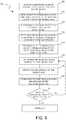
- FIG. 5is a block diagram illustrating a method 500 of monitoring nerve activity using the system 100 of FIGS. 1-4C or another suitable system in accordance with an embodiment of the present technology.
- the method 500can include intravascularly placing a neuromodulation assembly (e.g., the neuromodulation assembly 120 of FIG. 1 ) at a target site in a blood vessel (block 505), and deploying the neuromodulation assembly from a delivery state (e.g., a low-profile configuration) to a deployed state (e.g., an expanded configuration) to place two or more electrodes, contacts, and/or other energy delivery elements at least substantially in contact with the vessel wall (e.g., as shown in FIG. 3B ; block 510).
- a delivery statee.g., a low-profile configuration
- a deployed statee.g., an expanded configuration
- the method 500can further include recording electrical activity at the target site via the electrodes (block 515).
- the recorded electrical activitycan then be processed using a nerve monitoring assembly (e.g., the nerve monitoring assembly 128 of FIG. 1 ) operably coupled to the electrodes to detect ENG signals (block 520).
- the nerve monitoring assemblycan include an amplifier assembly that is electrically coupled to the electrodes in a QT, TT, and/or AT arrangement (e.g., as described above with reference to FIGS. 4A-4C ).
- neural activitycan be detected from several locations at and/or proximate to the target site (e.g., two or more positions along the length of the vessel; block 525), and the ENG signals from the various locations can be averaged to provide a baseline ENG of neural activity before neuromodulation.
- neural recordingscan be taken from different electrode pairs and compared to provide an understanding of the neural activity along the vessel and/or to select which electrode pair or pairs provide the best ENG signal (e.g., the clearest or strongest ENG signal).
- the operatormay optionally stimulate neural activity with a short current pulse supplied by one of the electrodes (e.g., a first electrode), and the other electrodes (e.g., a second, third, and/or fourth electrode) can be used to record the resultant neural activity.
- a short current pulsesupplied by one of the electrodes (e.g., a first electrode), and the other electrodes (e.g., a second, third, and/or fourth electrode) can be used to record the resultant neural activity.
- the method 500can continue by delivering neuromodulation energy to the target site via the electrodes (block 530).
- the same electrodes that are used to detect the neural activitycan be used to deliver the neuromodulation energy to the treatment site.
- different electrodescan be used for neuromodulation and recording.
- neuromodulation energycan be delivered to the target site using other modalities with various different types of energy applicators (e.g., cryotherapeutic applicators, ultrasound transducers, etc.).
- the method 500can further include detecting ENG signals proximate to the treatment site after the neuromodulation energy has been applied (block 535).
- the ENG signalscan be detected by the nerve monitoring assembly using the recordings taken from one or more pairs of electrodes and/or other contacts.
- the operatorcan optionally record neural activity from a plurality of different electrode pairs and/or at a plurality of locations proximate to the target site.
- the various neural recordingscan be compared with each other and/or averaged.
- the post-neuromodulation ENGcan then be compared with the ENG taken before neuromodulation (block 540).
- Decreases (e.g., substantial decreases) in a parameter (e.g., amplitude) of the ENG signals after neuromodulationmay indicate sufficient treatment of nerves proximate to the target site. For example, a decrease in amplitude of the ENG signals of 20%, 30%, 40%, 50%, 60%, 70%, 80%, and/or over 90% may indicate sufficient treatment of the target nerves.
- the method 500can then determine whether the nerves have been adequately modulated (block 545). For example, if the amplitude observed in ENG is below a threshold value, then the neuromodulation step may have effectively modulated or stopped conduction of the adjacent nerves and the neuromodulation process can be considered complete.
- the process of neuromodulating (block 530) and monitoring the resultant nerve activity (block 535)can be repeated until the nerves have been effectively modulated.
- the method 500can optionally be repeated after a time period (e.g., 5-30 minutes, 2 hours, 1 day, etc.) to confirm that the nerves were adequately ablated (e.g., rather than merely being stunned).
- the method 500 and the system 100 ( FIG. 1 ) used to implement the method 500can monitor neural activity and deliver therapeutic energy to modulate nerves to provide real time feedback of the effectiveness of a neuromodulation treatment.
- Both the recording of neural activity and the delivery of therapeutic energycan be provided by a single device (e.g., the neuromodulation catheter 102 ( FIG. 1 )), rather than a device dedicated to nerve monitoring and a separate device dedicated to neuromodulation that would each need to be delivered separately to the treatment site.
- the same elementse.g., electrodes
- the same signal wires that run along the length of a catheter to the electrodescan be used both to transmit recorded neural signals to the nerve monitoring assembly and deliver energy from the energy generator to the electrodes.
- the method 500can differentiate ENG signals from EMG signals using recordings taken intravascularly positioned electrodes.
- FIG. 6is a side view of a neuromodulation assembly 620 at a distal portion of a neuromodulation catheter configured in accordance with another embodiment of the present technology.
- the neuromodulation assembly 620includes various features generally similar to those of the neuromodulation assembly 120 described above with reference to FIGS. 1-3B .
- the neuromodulation assembly 620can be attached to a distal portion 608b of a shaft 608 and include a plurality of energy delivery elements 624 (e.g., electrodes) and/or contacts configured to contact a vessel wall V when the neuromodulation assembly 620 is in a deployed state (e.g., shown in FIG. 6 ).
- energy delivery elements 624e.g., electrodes
- the energy delivery elements 624are supported by an expandable mesh structure 650.
- the energy delivery elements 624may be proximate to, adjacent to, adhered to, and/or woven into the mesh structure 650.
- the energy delivery elements 624may also be formed by the mesh structure 650 itself (e.g., the fibers of the mesh may be capable of delivering energy). Whether the energy delivery elements 624 are mounted on or integrated into the mesh structure 650, the mesh structure 650 can be expanded such that the energy delivery elements 624 contact with the vessel wall V.
- the energy delivery elements 624may deliver power independently of each other (i.e., may be used in a monopolar fashion), either simultaneously or progressively, and/or may deliver power between any desired combination of the elements (i.e., may be used in a bipolar fashion).
- the energy delivery elements 624can perform a nerve monitoring function by detecting neural activity before and/or after in energy delivery.
- some of the energy delivery elements 624 and/or other contacts on the mesh structure 650can be configured solely for nerve recording and the other contacts can be configured for energy delivery.
- the neuromodulation assembly 620can further include a tube 652 or other type of shaft that extends through the length of the mesh structure 650, and a distal member 638 (e.g., a collar, shaft, or cap) at the distal end portion of the mesh structure 650 coupled to the tube 652.
- the distal member 638can include a rounded distal portion to provide atraumatic insertion of the neuromodulation assembly 620 into a vessel and an opening 654 that allows the neuromodulation assembly 620 to be threaded over a guide wire 656 for intravascular delivery to a target site.
- the shaft 608, the tube 652, the mesh structure 650, and/or the distal member 638may have a lumen sized and shaped to slideably accommodate a control wire 658.
- the control wire 658can facilitate the expansion and/or contraction of the mesh structure 650 when it is pulled or pushed (e.g., at the proximal end of the neuromodulation catheter). For example, pulling (i.e., an increase in tension) of control wire 658 may shorten the mesh structure 650 to increase its diameter placing it in an expanded configuration (e.g., FIG. 6 ), whereas pushing (i.e., an increase in compression) of control wire 658 may lengthen the mesh structure 650 to a compressed configuration. As shown in FIG.
- control wire 658can be a hollow tube that can be passed over the guide wire 656.
- control wire 658may be a solid structure (e.g., made from a metal or polymer). Further details and characteristics of neuromodulation assemblies with mesh structures are including in International Patent Application No. PCT/US2011/057153 (International Patent Application Publication No. WO2012/054862 ).
- FIG. 7is a side view of a neuromodulation assembly 720 at a distal portion of a neuromodulation catheter configured in accordance with yet another embodiment of the present technology.
- the neuromodulation assembly 720includes various features generally similar to those of the neuromodulation assemblies 120 and 620 described above.
- the neuromodulation assembly 720can be attached to a distal portion 708b of a shaft 708 and include a plurality of contacts or energy delivery elements 724 configured to be placed into contact with a vessel wall V when the neuromodulation assembly 720 is deployed within a vessel (e.g., FIG. 7 ).
- An atraumatic (e.g., rounded) distal member 738can be attached to the distal portion of the neuromodulation assembly 720 and can include a distal guide wire opening 754 to facilitate intravascular delivery of the neuromodulation assembly 720 to a target site.
- the neuromodulation assembly 720further includes a plurality of supports 760 that define an expandable basket structure and carry the energy delivery elements 724.
- the proximal ends of the supports 720can be attached or otherwise connected to the distal portion 708b of the shaft 708, and the distal ends of the supports 760 can be attached or otherwise connected to the distal member 738.
- At least one of the distal portion 708b of the shaft 708 and the distal member 738can be moveable along the longitudinal dimension A-A of the shaft 708 to transform the neuromodulation assembly 720 from a low-profile delivery state to an expanded deployed state in which the energy delivery elements 724 contact in the inner wall V of at a target site.
- the energy delivery elements 724can be spaced angularly apart from each other around the longitudinal dimension A-A of the shaft 708 at a common area along the length of the longitudinal dimension A-A. This arrangement places the energy delivery elements 724 in contact with the vessel wall V to provide an at least substantially circumferential exposure (e.g., for neural recording and/or neuromodulation) in a common plane perpendicular to the longitudinal dimension A-A of the shaft 708.
- the energy delivery elements 724can have other suitable configurations.
- one or more energy delivery elements 724can be spaced along the length of the supports 760 to provide nerve monitoring and/or neuromodulation at different zones along the length of the vessel and/or the neuromodulation assembly 720 can include a different number of supports 760 than the four supports 760 illustrated in FIG. 7 (e.g., to provide nerves with more fully circumferential exposure the energy delivery elements 724).
- the energy delivery elements 724can be positioned in a staggered relationship relative to each other along the length of the neuromodulation assembly 720.
- first electrodes 724a(shown in broken lines) at a proximal portion of two of the supports 760 can be longitudinally offset from second energy delivery elements 724b (shown in broken lines) on distal portions of two other longitudinal supports 760.
- the first electrodes 724acan also be angularly offset from the second electrodes 724b by, for example, 90° or some other suitable angle.
- the energy delivery elements 724can be electrodes configured to provide both energy delivery (e.g., RF energy) and recording of electrical activity at the target site. In other embodiments, some of the energy delivery elements 724 can serve solely as contacts for detecting neural signals while others are configured for energy delivery. In further embodiments, at least some of the energy delivery elements 724 can be configured to provide a form of energy other than electrical current (e.g., RF energy) to the target site, while others can provide the nerve monitoring function. For example, at least some of the energy delivery elements 724 can be defined by radiation emitters that expose target nerves to radiation at a wavelength that causes a previously administered photosensitizer to react, such that it damages or disrupts the nerves.
- energy delivery elements 724can be defined by radiation emitters that expose target nerves to radiation at a wavelength that causes a previously administered photosensitizer to react, such that it damages or disrupts the nerves.
- the radiation emitterscan be optical elements coupled to fiber optic cables (e.g., extending through the shaft 708) for delivering radiation from a radiation source (e.g., an energy generator) at an extracorporeal location to the target tissue at the vessel, or may be internal radiation sources (e.g., LEDs) that are electrically coupled to a power source at an extracorporeal location via electrical leads within the shaft 708.
- a radiation sourcee.g., an energy generator
- internal radiation sourcese.g., LEDs
- a photosensitizere.g., oxytetracycline, a suitable tetracycline analog, and/or other suitable photosensitive compounds that preferentially bind to neural tissue
- a photosensitizercan be administered to a patient (e.g., orally, via injection, through an intravascular device, etc.), and preferentially accumulate at selected nerves (e.g., rather than other tissues proximate to the selected nerves).
- selected nervese.g., rather than other tissues proximate to the selected nerves.
- more of the photosensitizercan accumulate in perivascular nerves around a blood vessel than in the non-neural tissues of the blood vessel.
- the mechanisms for preferentially accumulating the photosensitizer at the nervescan include faster uptake by the nerves, longer residual times at the nerves, or a combination of both.
- the photosensitizercan be irradiated using energy delivery elements 724.
- the energy delivery elements 724can deliver radiation to the target nerves at a wavelength that causes the photosensitizer to react such that it damages or disrupts the nerves.
- the photosensitizercan become toxic upon exposure to the radiation. Because the photosensitizer preferentially accumulates at the nerves and not the other tissue proximate the nerves, the toxicity and corresponding damage is localized primarily at the nerves.
- irradiative neuromodulationcan also or alternatively be incorporated in any one of the neuromodulation assemblies described herein. Further details and characteristics of neuromodulation assemblies with radiation emitters are included in U.S. Patent Application No. 13/826,604 , published as US2014/0005591 .
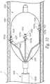
- FIG. 8is a side view of a neuromodulation assembly 820 at a distal portion of a neuromodulation catheter configured in accordance with a further embodiment of the present technology.
- the neuromodulation assembly 820includes various features generally similar to the features of the neuromodulation assemblies 120, 620 and 720 described above.
- the neuromodulation assembly 820can be attached to a distal portion 808b of a shaft 808 and include a plurality of energy delivery elements or contacts 824 configured to be placed into contact with a vessel wall V when the neuromodulation assembly 820 is deployed within a vessel (e.g., FIG. 8 ).
- FIG. 8illustrates the embodiment illustrated in FIG.
- the contacts 824are carried by an outer expandable body 862 (e.g., a balloon) that positions the contacts 824 against a vessel wall V when the expandable body 862 is deployed (e.g., inflated or otherwise expanded) within the vessel.
- the shaft 808 and/or another suitable elongated member connected to the shaft 808can extend at least partially through the expandable body 862 and carry an ultrasound transducer 864.
- the ultrasound transducer 864may be configured to provide therapeutically effective energy (e.g., HIFU) and, optionally, provide imaging information that may facilitate placement of the transducer 864 relative to a blood vessel, optimize energy delivery, and/or provide tissue feedback (e.g. to determine when treatment is complete).
- the lesion created by the application of ultrasound energymay be limited to very specific areas (e.g., focal zones or focal points) on the periphery of the vessel wall V or on the nerves themselves.
- the average ultrasound intensity for neural modulatione.g., ablation of renal nerves
- the neuromodulation assembly 820further includes an inner expandable body 866 (e.g., a balloon) positioned within the outer expandable body 862 and around the ultrasound transducer 864.
- the inner expandable body 866can be filled with a sound-conducting medium (e.g. water, a conductive medium, etc.) and act as an acoustic lens and transmission media for the emitted ultrasonic energy.
- the waves emitted by the ultrasound transducer 864can be formed into one or more focal beams focusing on corresponding focal points or regions 868 (e.g., about 0-5 mm deep in the surrounding tissue).
- other featurese.g., an acoustically reflective material
- the outer expandable body 862may be configured to position the contacts 824 away from the waves emitted by the ultrasound transducer 864 to avoid undesirably heating the contacts 824.
- the outer expandable body 862can be filled with a gas to contain the energy emitted by the ultrasound transducer 864 and inhibit it from escaping in the undesired directions.
- This form of ultrasound-based neuromodulationcan also or alternatively be incorporated in any one of the neuromodulation assemblies described above or below. Additional features and alternative embodiments of ultrasoundinduced neuromodulation devices are disclosed in U.S. Patent Application No. 12/940,0922 ( U.S. Patent Publication No. 2011/0112400 ).
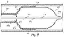
- FIG. 9is a partial cross-sectional side view of a neuromodulation assembly 920 at a distal portion of a neuromodulation catheter configured in accordance with yet another embodiment of the present technology.
- the neuromodulation assembly 920includes various features generally similar to the features of the neuromodulation assemblies 120, 620, 720 and 820 described above.
- the neuromodulation assembly 920can be attached to a distal portion 908b of a shaft 908 and include a plurality of energy delivery elements or contacts 924 configured to be placed into contact with a vessel wall V when the neuromodulation assembly 920 is deployed within a vessel (e.g., FIG. 9 ). As shown in FIG.
- the energy delivery elements 924can be electrically coupled to corresponding conductive leads 970 (e.g., electrical wires) that extend through or along the shaft 908.
- the leads 970can operably couple the energy delivery elements 924 to an energy source (e.g., the energy generator 126 of FIG. 1 ) and/or a nerve monitoring assembly (e.g., the nerve monitoring assembly 128 of FIG. 1 ) at a proximal portion of the shaft 908.
- the neuromodulation assembly 920can further include a cryogenic applicator 972 (e.g., a balloon or other expandable member) that can expand radially outward to press or otherwise contact the inner surface of the vessel wall V.
- the cryogenic applicator 972can define at least a portion of an expansion chamber in which a refrigerant expands or otherwise flows to provide cryogenic cooling.
- a supply lumen 974can be fluidly coupled to a refrigerant source (e.g., a refrigerant cartridge or canister; not shown) at its proximal end portion, and may be sized to retain at least a portion of the refrigerant that reaches the expansion chamber at a high pressure liquid state.
- the supply lumen 974can include one or more orifices or openings 976 from which refrigerant can expand into the expansion chamber, or refrigerant can be configured to expand from a distal opening of a capillary tube (not shown) extending from the supply lumen 974.
- the openings 976may have a cross-sectional area less than that of the supply lumen 974 to impede the flow of refrigerant proximate the expansion chamber, thereby increasing the pressure drop of the refrigerant entering the expansion chamber and concentrating the refrigeration power at the cryogenic applicator 974.
- the openings 976can be sized relative to the area and/or length of an exhaust lumen (e.g., defined by a distal portion of the shaft 908) to provide a sufficient flow rate of refrigerant, produce a sufficient pressure drop when the refrigerant enters the expansion chamber, and allow for sufficient venting of expanded refrigerant through the shaft 908 to establish and maintain cooling at the cryogenic applicator 972.
- an exhaust lumene.g., defined by a distal portion of the shaft 908
- a liquid refrigerantcan expand into a gaseous phase as it passes through the openings 976 of the supply lumen 974 into the expansion chamber (defined by at least a portion of the cryogenic applicator 974), thereby inflating the cryogenic applicator 972.
- the expansion of the refrigerantcauses a temperature drop in the expansion chamber, thereby forming one or more cooling zones around at least a portion of the cryogenic applicator 972.
- the cooling zones created by the cryogenic applicator 972can provide therapeutically effective cooling to nerves proximate to the vessel wall V, while the contacts 924 serve a nerve monitoring function.
- cryogenic applicator 972can be provided by a non-expandable member, such a cryoprobe at the distal portion 908b of the shaft 908 (e.g., a FREEZOR catheter available from Medtronic, Inc. of Minneapolis, Minnesota).
- a non-expandable membersuch as a cryoprobe at the distal portion 908b of the shaft 908 (e.g., a FREEZOR catheter available from Medtronic, Inc. of Minneapolis, Minnesota).
- the contacts 924can be configured to provide resistive heating in and/or at the tissue to raise the temperatures at hyperthermic zones in the vessel wall V and the surrounding neural fibers to provide therapeutically-effective neuromodulation
- the cryogenic applicator 972can be configured to form non-therapeutic cooling zones before, during, and/or after the delivery of hyperthermic energy by the contacts 924.
- the cooling zonecan be provided at a relatively low refrigeration power, e.g., a power less than that required to induce neuromodulation.
- the cooling zonecan cool the contacts 924 and/or the body tissue at or proximate to the target site (e.g., the inner surface of vessel wall V).
- the cooling zone provided by the cryogenic applicator 972is expected to maintain lower temperatures, and thereby reduce thermal trauma in the tissue proximate the inner surface of the vessel wall V during hyperthermic neuromodulation.
- the hyperthermic zonemay also extend or focus more on the exterior area of the vessel wall V where the nerves reside. Therefore, the neuromodulation assembly 920 can provide a reverse thermal gradient across a portion of the vessel wall V to provide hyperthermic neuromodulation at a depth in the tissue, while reducing potential hyperthermal effects on the vessel tissue closer to the neuromodulation assembly 920.
- cryotherapeutic neuromodulation and/or cryogenic cooling described abovecan also or alternatively be incorporated in any one of the neuromodulation assemblies described above. Further details and characteristics of neuromodulation assemblies with cryogenic applicators are included in International Patent Application No. PCT/US2011/057514 , published as WO20121058165 , and U.S. Patent Application No. 13/458,859 , published as US2013/0289678 .
- FIG. 10is a side view of a neuromodulation assembly 1020 at a distal portion of a neuromodulation catheter configured in accordance with yet another embodiment of the present technology.
- the neuromodulation assembly 1020includes various features generally similar to the features of the neuromodulation assemblies 120, 620, 720, 820 and 920 described above.
- the neuromodulation assembly 1020can be attached to a distal portion 1008b of a shaft 1008 and include a plurality of energy delivery elements or contacts 1024 configured to be placed into contact proximate to a vessel wall V when the neuromodulation assembly 1020 is deployed within a vessel.
- Each energy delivery element 1024can be a bipolar element having one or more oppositely biased contact pairs.
- the energy delivery elements 1024can each have a row of positive contacts 1025a and a row of negative contacts 1025b. In operation, a small electrical field is established between the positive contacts 1025a and the negative contacts 1025b.
- Each energy delivery element 1024can also include a thermistor 1026.
- the energy delivery elements 1024 with the various contacts 1025a-b and thermistors 1026can be flex circuits attached to the balloon 1080 or printed directly onto the balloon 1080.
- the neuromodulation assembly 1020can further include a balloon 1080 or other expandable member that carries the energy delivery elements 1024 (e.g., electrodes).
- the balloon 1080can be inflated with a fluid to place the energy delivery elements 1024 in contact with the vessel wall V and, optionally, occlude the vessel.
- the balloon 1080can be inflated by injecting a gas into the balloon 1080 via an inflation lumen (not shown) that extends along the length of the shaft 1008.
- a fluide.g., a gas, a cryogenic fluid
- the plurality of energy delivery elements 1024can be electrically coupled to a corresponding plurality of leads 1070 that are coupled to or positioned about the expandable member 1080.
- the leads 1070can be part of a flex circuit that easily expands or collapses with the expandable member 1080.
- the leads 1070can be electrically coupled to an energy source (e.g., the energy generator 126 of FIG. 1 ) and/or a nerve monitoring assembly (e.g., the nerve monitoring assembly 128 of FIG. 1 ) at a proximal portion of the shaft 1008 by wires that extend through or along the shaft 1008 or via a wireless connection.
- the energy delivery elements 1024can provide both a nerve recording function and a neuromodulation function.
- the energy delivery elements 1024are defined by individual bipolar point electrodes that are spaced at multiple lengthwise and angular positions relative to the outer surface of the balloon 1080 and the vessel wall V.
- the four energy delivery elements 1024 shown in FIG. 10can be angularly offset from each other by about 90°.
- the energy delivery elements 1024can be angularly offset from each other by different degrees (e.g., 60°, 80°, 180°, etc.) depending on the number of energy delivery elements 1024 and/or their relative spacing along the length of the balloon 1080.
- the lengthwise and/or angularly offset energy delivery elements 1024can provide non-continuous circumferential neuromodulation and/or neural recording without having to reposition the neuromodulation assembly 1020.
- the illustrated embodimentshows four energy delivery elements 1024, but other embodiments can include different numbers of energy delivery elements (e.g., 1-12 energy delivery elements 1024).
- the energy delivery elements 1024can have other suitable configurations on the outer surface of the balloon 1080, and/or the energy delivery elements 1024 may have other suitable structures.
- one or more of the energy delivery elements 1024can be defined by circular electrodes and/or spiral-shaped electrodes that extend around the outer surface of the balloon 1080. Such configurations can provide partial or full circumferential neuromodulation and/or neural recording along the vessel wall V.
- Renal neuromodulationis the partial or complete incapacitation or other effective disruption of nerves of the kidneys (e.g., nerves terminating in the kidneys or in structures closely associated with the kidneys).
- renal neuromodulationcan include inhibiting, reducing, and/or blocking neural communication along neural fibers (e.g., efferent and/or afferent neural fibers) of the kidneys.
- Such incapacitationcan be long-term (e.g., permanent or for periods of months, years, or decades) or short-term (e.g., for periods of minutes, hours, days, or weeks).
- Renal neuromodulationis expected to contribute to the systemic reduction of sympathetic tone or drive and/or to benefit at least some specific organs and/or other bodily structures innervated by sympathetic nerves. Accordingly, renal neuromodulation is expected to be useful in treating clinical conditions associated with systemic sympathetic overactivity or hyperactivity, particularly conditions associated with central sympathetic overstimulation. For example, renal neuromodulation is expected to efficaciously treat hypertension, heart failure, acute myocardial infarction, metabolic syndrome, insulin resistance, diabetes, left ventricular hypertrophy, chronic and end stage renal disease, inappropriate fluid retention in heart failure, cardio-renal syndrome, polycystic kidney disease, polycystic ovary syndrome, osteoporosis, erectile dysfunction, and sudden death, among other conditions.
- Renal neuromodulationcan be electrically-induced, thermally-induced, chemically-induced, or induced in another suitable manner or combination of manners at one or more suitable target sites during a treatment procedure.
- the target sitecan be within or otherwise proximate to a renal lumen (e.g., a renal artery, a ureter, a renal pelvis, a major renal calyx, a minor renal calyx, or another suitable structure), and the treated tissue can include tissue at least proximate to a wall of the renal lumen.
- a treatment procedurecan include modulating nerves in the renal plexus, which lay intimately within or adjacent to the adventitia of the renal artery.
- Renal neuromodulationcan include a cryotherapeutic treatment modality alone or in combination with another treatment modality.
- Cryotherapeutic treatmentcan include cooling tissue at a target site in a manner that modulates neural function.
- sufficiently cooling at least a portion of a sympathetic renal nervecan slow or potentially block conduction of neural signals to produce a prolonged or permanent reduction in renal sympathetic activity.
- cryotherapeutic tissue damagecan include, for example, direct cell injury (e.g., necrosis), vascular or luminal injury (e.g., starving cells from nutrients by damaging supplying blood vessels), and/or sublethal hypothermia with subsequent apoptosis.
- Exposure to cryotherapeutic coolingcan cause acute cell death (e.g., immediately after exposure) and/or delayed cell death (e.g., during tissue thawing and subsequent hyperperfusion).
- Neuromodulation using a cryotherapeutic treatment in accordance with embodiments of the present technologycan include cooling a structure proximate an inner surface of a body lumen wall such that tissue is effectively cooled to a depth where sympathetic renal nerves reside.
- a cooling assembly of a cryotherapeutic devicecan be cooled to the extent that it causes therapeutically-effective, cryogenic renal neuromodulation.
- a cryotherapeutic treatment modalitycan include cooling that is not configured to cause neuromodulation.
- the coolingcan be at or above cryogenic temperatures and can be used to control neuromodulation via another treatment modality (e.g., to protect tissue from neuromodulating energy).
- Renal neuromodulationcan include an electrode-based or transducer-based treatment modality alone or in combination with another treatment modality.
- Electrode-based or transducer-based treatmentcan include delivering electricity and/or another form of energy to tissue at a treatment location to stimulate and/or heat the tissue in a manner that modulates neural function. For example, sufficiently stimulating and/or heating at least a portion of a sympathetic renal nerve can slow or potentially block conduction of neural signals to produce a prolonged or permanent reduction in renal sympathetic activity.
- a variety of suitable types of energycan be used to stimulate and/or heat tissue at a treatment location.
- neuromodulation in accordance with embodiments of the present technologycan include delivering RF energy, pulsed energy, microwave energy, optical energy, focused ultrasound energy (e.g., high-intensity focused ultrasound energy), or another suitable type of energy alone or in combination.
- An electrode or transducer used to deliver this energycan be used alone or with other electrodes or transducers in a multi-electrode or multi-transducer array.
- the energycan be applied from within the body (e.g., within the vasculature or other body lumens in a catheter-based approach) and/or from outside the body (e.g., via an applicator positioned outside the body).
- energycan be used to reduce damage to non-targeted tissue when targeted tissue adjacent to the non-targeted tissue is subjected to neuromodulating cooling.
- Focused ultrasoundis an example of a transducer-based treatment modality that can be delivered from outside the body. Focused ultrasound treatment can be performed in close association with imaging (e.g., magnetic resonance, computed tomography, fluoroscopy, ultrasound (e.g., intravascular or intraluminal), optical coherence tomography, or another suitable imaging modality). For example, imaging can be used to identify an anatomical position of a treatment location (e.g., as a set of coordinates relative to a reference point).
- imagingcan be used to identify an anatomical position of a treatment location (e.g., as a set of coordinates relative to a reference point).
- the coordinatescan then entered into a focused ultrasound device configured to change the power, angle, phase, or other suitable parameters to generate an ultrasound focal zone at the location corresponding to the coordinates.
- the focal zonecan be small enough to localize therapeutically-effective heating at the treatment location while partially or fully avoiding potentially harmful disruption of nearby structures.
- the ultrasound devicecan be configured to pass ultrasound energy through a lens, and/or the ultrasound energy can be generated by a curved transducer or by multiple transducers in a phased array (curved or straight).
- Heating effects of electrode-based or transducer-based treatmentcan include ablation and/or non-ablative alteration or damage (e.g., via sustained heating and/or resistive heating).
- a treatment procedurecan include raising the temperature of target neural fibers to a target temperature above a first threshold to achieve non-ablative alteration, or above a second, higher threshold to achieve ablation.
- the target temperaturecan be higher than about body temperature (e.g., about 37°C) but less than about 45°C for non-ablative alteration, and the target temperature can be higher than about 45°C for ablation.
- Heating tissue to a temperature between about body temperature and about 45°Ccan induce non-ablative alteration, for example, via moderate heating of target neural fibers or of vascular or luminal structures that perfuse the target neural fibers. In cases where vascular structures are affected, the target neural fibers can be denied perfusion resulting in necrosis of the neural tissue. Heating tissue to a target temperature higher than about 45°C (e.g., higher than about 60°C) can induce ablation, for example, via substantial heating of target neural fibers or of vascular or luminal structures that perfuse the target fibers.
- tissueit can be desirable to heat tissue to temperatures that are sufficient to ablate the target neural fibers or the vascular or luminal structures, but that are less than about 90°C (e.g., less than about 85°C, less than about 80°C, or less than about 75°C).
- Renal neuromodulationcan include a chemical-based treatment modality alone or in combination with another treatment modality.
- Neuromodulation using chemical-based treatmentcan include delivering one or more chemicals (e.g., drugs or other agents) to tissue at a treatment location in a manner that modulates neural function.
- the chemicalfor example, can be selected to affect the treatment location generally or to selectively affect some structures at the treatment location over other structures.
- the chemicalfor example, can be guanethidine, ethanol, phenol, a neurotoxin, or another suitable agent selected to alter, damage, or disrupt nerves.
- a variety of suitable techniquescan be used to deliver chemicals to tissue at a treatment location.
- chemicalscan be delivered via one or more needles originating outside the body or within the vasculature or other body lumens.
- a cathetercan be used to intravascularly position a therapeutic element including a plurality of needles (e.g., micro-needles) that can be retracted or otherwise blocked prior to deployment.
- a chemicalcan be introduced into tissue at a treatment location via simple diffusion through a body lumen wall, electrophoresis, or another suitable mechanism. Similar techniques can be used to introduce chemicals that are not configured to cause neuromodulation, but rather to facilitate neuromodulation via another treatment modality.
- the sympathetic nervous systemis a branch of the autonomic nervous system along with the enteric nervous system and parasympathetic nervous system. It is always active at a basal level (called sympathetic tone) and becomes more active during times of stress.
- the sympathetic nervous systemoperates through a series of interconnected neurons. Sympathetic neurons are frequently considered part of the peripheral nervous system (PNS), although many lie within the central nervous system (CNS).
- Sympathetic neurons of the spinal cord(which is part of the CNS) communicate with peripheral sympathetic neurons via a series of sympathetic ganglia. Within the ganglia, spinal cord sympathetic neurons join peripheral sympathetic neurons through synapses. Spinal cord sympathetic neurons are therefore called presynaptic (or preganglionic) neurons, while peripheral sympathetic neurons are called postsynaptic (or postganglionic) neurons.
- preganglionic sympathetic neuronsrelease acetylcholine, a chemical messenger that binds and activates nicotinic acetylcholine receptors on postganglionic neurons.
- postganglionic neuronsprincipally release noradrenaline (norepinephrine). Prolonged activation may elicit the release of adrenaline from the adrenal medulla.
- norepinephrine and epinephrinebind adrenergic receptors on peripheral tissues. Binding to adrenergic receptors causes a neuronal and hormonal response. The physiologic manifestations include pupil dilation, increased heart rate, occasional vomiting, and increased blood pressure. Increased sweating is also seen due to binding of cholinergic receptors of the sweat glands.
- the sympathetic nervous systemis responsible for up- and down-regulating many homeostatic mechanisms in living organisms. Fibers from the SNS innervate tissues in almost every organ system, providing at least some regulatory function to physiological features as diverse as pupil diameter, gut motility, and urinary output. This response is also known as sympatho-adrenal response of the body, as the preganglionic sympathetic fibers that end in the adrenal medulla (but also all other sympathetic fibers) secrete acetylcholine, which activates the secretion of adrenaline (epinephrine) and to a lesser extent noradrenaline (norepinephrine). Therefore, this response that acts primarily on the cardiovascular system is mediated directly via impulses transmitted through the sympathetic nervous system and indirectly via catecholamines secreted from the adrenal medulla.
- the SNSprovides a network of nerves that allows the brain to communicate with the body.
- Sympathetic nervesoriginate inside the vertebral column, toward the middle of the spinal cord in the intermediolateral cell column (or lateral horn), beginning at the first thoracic segment of the spinal cord and are thought to extend to the second or third lumbar segments. Because its cells begin in the thoracic and lumbar regions of the spinal cord, the SNS is said to have a thoracolumbar outflow. Axons of these nerves leave the spinal cord through the anterior rootlet/root. They pass near the spinal (sensory) ganglion, where they enter the anterior rami of the spinal nerves.
- the axonsIn order to reach the target organs and glands, the axons should travel long distances in the body, and, to accomplish this, many axons relay their message to a second cell through synaptic transmission. The ends of the axons link across a space, the synapse, to the dendrites of the second cell. The first cell (the presynaptic cell) sends a neurotransmitter across the synaptic cleft where it activates the second cell (the postsynaptic cell). The message is then carried to the final destination.
- gangliaIn the SNS and other components of the peripheral nervous system, these synapses are made at sites called ganglia, discussed above.
- the cell that sends its fiberis called a preganglionic cell, while the cell whose fiber leaves the ganglion is called a postganglionic cell.
- the preganglionic cells of the SNSare located between the first thoracic (T1) segment and third lumbar (L3) segments of the spinal cord.
- Postganglionic cellshave their cell bodies in the ganglia and send their axons to target organs or glands.
- the gangliainclude not just the sympathetic trunks but also the cervical ganglia (superior, middle and inferior), which sends sympathetic nerve fibers to the head and thorax organs, and the celiac and mesenteric ganglia (which send sympathetic fibers to the gut).
- the kidneyis innervated by the renal plexus (RP), which is intimately associated with the renal artery.
- the renal plexus (RP)is an autonomic plexus that surrounds the renal artery and is embedded within the adventitia of the renal artery.
- the renal plexus (RP)extends along the renal artery until it arrives at the substance of the kidney. Fibers contributing to the renal plexus (RP) arise from the celiac ganglion, the superior mesenteric ganglion, the aorticorenal ganglion and the aortic plexus.
- the renal plexus (RP)also referred to as the renal nerve, is predominantly comprised of sympathetic components. There is no (or at least very minimal) parasympathetic innervation of the kidney.
- Preganglionic neuronal cell bodiesare located in the intermediolateral cell column of the spinal cord. Preganglionic axons pass through the paravertebral ganglia (they do not synapse) to become the lesser splanchnic nerve, the least splanchnic nerve, first lumbar splanchnic nerve, second lumbar splanchnic nerve, and travel to the celiac ganglion, the superior mesenteric ganglion, and the aorticorenal ganglion. Postganglionic neuronal cell bodies exit the celiac ganglion, the superior mesenteric ganglion, and the aorticorenal ganglion to the renal plexus (RP) and are distributed to the renal vasculature.
- RPrenal plexus
- Efferent messagesmay trigger changes in different parts of the body simultaneously.
- the sympathetic nervous systemmay accelerate heart rate; widen bronchial passages; decrease motility (movement) of the large intestine; constrict blood vessels; increase peristalsis in the esophagus; cause pupil dilation, piloerection (goose bumps) and perspiration (sweating); and raise blood pressure.
- Afferent messagescarry signals from various organs and sensory receptors in the body to other organs and, particularly, the brain.
- renin-angiotensin-aldosterone systemhas been a longstanding, but somewhat ineffective, approach for reducing over-activity of the SNS.
- the renal sympathetic nervous systemhas been identified as a major contributor to the complex pathophysiology of hypertension, states of volume overload (such as heart failure), and progressive renal disease, both experimentally and in humans.
- Studies employing radiotracer dilution methodology to measure overflow of norepinephrine from the kidneys to plasmarevealed increased renal norepinephrine (NE) spillover rates in patients with essential hypertension, particularly so in young hypertensive subjects, which in concert with increased NE spillover from the heart, is consistent with the hemodynamic profile typically seen in early hypertension and characterized by an increased heart rate, cardiac output, and renovascular resistance.
- NErenal norepinephrine
- Sympathetic nerves to the kidneysterminate in the blood vessels, the juxtaglomerular apparatus and the renal tubules. Stimulation of the renal sympathetic nerves causes increased renin release, increased sodium (Na + ) reabsorption, and a reduction of renal blood flow. These components of the neural regulation of renal function are considerably stimulated in disease states characterized by heightened sympathetic tone and clearly contribute to the rise in blood pressure in hypertensive patients. The reduction of renal blood flow and glomerular filtration rate as a result of renal sympathetic efferent stimulation is likely a cornerstone of the loss of renal function in cardio-renal syndrome, which is renal dysfunction as a progressive complication of chronic heart failure, with a clinical course that typically fluctuates with the patient's clinical status and treatment.
- Pharmacologic strategies to thwart the consequences of renal efferent sympathetic stimulationinclude centrally acting sympatholytic drugs, beta blockers (intended to reduce renin release), angiotensin converting enzyme inhibitors and receptor blockers (intended to block the action of angiotensin II and aldosterone activation consequent to renin release) and diuretics (intended to counter the renal sympathetic mediated sodium and water retention).
- the current pharmacologic strategieshave significant limitations including limited efficacy, compliance issues, side effects and others.
- the kidneyscommunicate with integral structures in the central nervous system via renal sensory afferent nerves.
- renal injurymay induce activation of sensory afferent signals.
- renal ischemia, reduction in stroke volume or renal blood flow, or an abundance of adenosine enzymemay trigger activation of afferent neural communication.
- this afferent communicationmight be from the kidney to the brain or might be from one kidney to the other kidney (via the central nervous system).
- These afferent signalsare centrally integrated and may result in increased sympathetic outflow.
- This sympathetic driveis directed towards the kidneys, thereby activating the RAAS and inducing increased renin secretion, sodium retention, volume retention and vasoconstriction.
- Central sympathetic over activityalso impacts other organs and bodily structures innervated by sympathetic nerves such as the heart and the peripheral vasculature, resulting in the described adverse effects of sympathetic activation, several aspects of which also contribute to the rise in blood pressure.
- renal denervationis likely to be valuable in the treatment of several clinical conditions characterized by increased overall and particularly renal sympathetic activity such as hypertension, metabolic syndrome, insulin resistance, diabetes, left ventricular hypertrophy, chronic end stage renal disease, inappropriate fluid retention in heart failure, cardio-renal syndrome, and sudden death.
- renal denervationmight also be useful in treating other conditions associated with systemic sympathetic hyperactivity.
- renal denervationmay also benefit other organs and bodily structures innervated by sympathetic nerves, including those identified in FIG. 11 .
- a reduction in central sympathetic drivemay reduce the insulin resistance that afflicts people with metabolic syndrome and Type II diabetics.
- patients with osteoporosisare also sympathetically activated and might also benefit from the down regulation of sympathetic drive that accompanies renal denervation.
- neuromodulation of a left and/or right renal plexusmay be achieved through intravascular access.
- FIG. 14Ablood moved by contractions of the heart is conveyed from the left ventricle of the heart by the aorta.
- the aortadescends through the thorax and branches into the left and right renal arteries.
- Below the renal arteriesthe aorta bifurcates at the left and right iliac arteries.
- the left and right iliac arteriesdescend, respectively, through the left and right legs and join the left and right femoral arteries.
- the bloodcollects in veins and returns to the heart, through the femoral veins into the iliac veins and into the inferior vena cava.
- the inferior vena cavabranches into the left and right renal veins. Above the renal veins, the inferior vena cava ascends to convey blood into the right atrium of the heart. From the right atrium, the blood is pumped through the right ventricle into the lungs, where it is oxygenated. From the lungs, the oxygenated blood is conveyed into the left atrium. From the left atrium, the oxygenated blood is conveyed by the left ventricle back to the aorta.
- the femoral arterymay be accessed and cannulated at the base of the femoral triangle just inferior to the midpoint of the inguinal ligament.
- a cathetermay be inserted percutaneously into the femoral artery through this access site, passed through the iliac artery and aorta, and placed into either the left or right renal artery. This comprises an intravascular path that offers minimally invasive access to a respective renal artery and/or other renal blood vessels.
- the wrist, upper arm, and shoulder regionprovide other locations for introduction of catheters into the arterial system.
- catheterization of either the radial, brachial, or axillary arterymay be utilized in select cases.
- Catheters introduced via these access pointsmay be passed through the subclavian artery on the left side (or via the subclavian and brachiocephalic arteries on the right side), through the aortic arch, down the descending aorta and into the renal arteries using standard angiographic technique.
- properties and characteristics of the renal vasculaturemay impose constraints upon and/or inform the design of apparatus, systems, and methods for achieving such renal neuromodulation. Some of these properties and characteristics may vary across the patient population and/or within a specific patient across time, as well as in response to disease states, such as hypertension, chronic kidney disease, vascular disease, end-stage renal disease, insulin resistance, diabetes, metabolic syndrome, etc. These properties and characteristics, as explained herein, may have bearing on the efficacy of the procedure and the specific design of the intravascular device. Properties of interest may include, for example, material/mechanical, spatial, fluid dynamic/hemodynamic and/or thermodynamic properties.
- a cathetermay be advanced percutaneously into either the left or right renal artery via a minimally invasive intravascular path.
- minimally invasive renal arterial accessmay be challenging, for example, because as compared to some other arteries that are routinely accessed using catheters, the renal arteries are often extremely tortuous, may be of relatively small diameter, and/or may be of relatively short length.
- renal arterial atherosclerosisis common in many patients, particularly those with cardiovascular disease. Renal arterial anatomy also may vary significantly from patient to patient, which further complicates minimally invasive access.
- Sufficient energyshould be delivered to or heat removed from the target renal nerves to modulate the target renal nerves without excessively cooling or heating the vessel wall to the extent that the wall is frozen, desiccated, or otherwise potentially affected to an undesirable extent.
- a potential clinical complication associated with excessive heatingis thrombus formation from coagulating blood flowing through the artery. Given that this thrombus may cause a kidney infarct, thereby causing irreversible damage to the kidney, thermal treatment from within the renal artery should be applied carefully.
- the complex fluid mechanics and thermodynamic conditions present in the renal artery during treatmentmay be important in applying energy (e.g., heating thermal energy) and/or removing heat from the tissue (e.g., cooling thermal conditions) from within the renal artery.
- energye.g., heating thermal energy
- tissuee.g., cooling thermal conditions
- the neuromodulatory apparatusshould also be configured to allow for adjustable positioning and repositioning of the energy delivery element within the renal artery since location of treatment may also impact clinical efficacy. For example, it may be helpful to apply a full circumferential treatment from within the renal artery given that the renal nerves may be spaced circumferentially around a renal artery. In some situations, a full-circle lesion likely resulting from a continuous circumferential treatment may be potentially related to renal artery stenosis. Therefore, the formation of more complex lesions along a longitudinal dimension of the renal artery and/or repositioning of the neuromodulatory apparatus to multiple treatment locations may be desirable.
- a benefit of creating a circumferential ablationmay outweigh the potential of renal artery stenosis or the risk may be mitigated with certain embodiments or in certain patients and creating a circumferential ablation could be a goal.
- variable positioning and repositioning of the neuromodulatory apparatusmay prove to be useful in circumstances where the renal artery is particularly tortuous or where there are proximal branch vessels off the renal artery main vessel, making treatment in certain locations challenging.
- Manipulation of a device in a renal arteryshould also consider mechanical injury imposed by the device on the renal artery. Motion of a device in an artery, for example by inserting, manipulating, negotiating bends and so forth, may contribute to dissection, perforation, denuding intima, or disrupting the interior elastic lamina.
- Blood flow through a renal arterymay be temporarily occluded for a short time with minimal or no complications.
- occlusion for a significant amount of timeshould be avoided because to prevent injury to the kidney such as ischemia. It could be beneficial to avoid occlusion all together or, if occlusion is beneficial to the embodiment, to limit the duration of occlusion, for example to 2-5 minutes.
- various independent and dependent properties of the renal vasculatureinclude, for example, (a) vessel diameter, vessel length, intima-media thickness, coefficient of friction, and tortuosity; (b) distensibility, stiffness and modulus of elasticity of the vessel wall; (c) peak systolic, end-diastolic blood flow velocity, as well as the mean systolic-diastolic peak blood flow velocity, and mean/max volumetric blood flow rate; (d) specific heat capacity of blood and/or of the vessel wall, thermal conductivity of blood and/or of the vessel wall, and/or thermal convectivity of blood flow past a vessel wall treatment site and/or radiative heat transfer;
- Renal artery vessel diameter, D RAtypically is in a range of about 2-10 mm, with most of the patient population having a D RA of about 4 mm to about 8 mm and an average of about 6 mm.
- Renal artery vessel length, L RAbetween its ostium at the aorta/renal artery juncture and its distal branchings, generally is in a range of about 5-70 mm, and a significant portion of the patient population is in a range of about 20-50 mm.
- the composite Intima-Media Thickness, IMT(i.e., the radial outward distance from the artery's luminal surface to the adventitia containing target neural structures) also is notable and generally is in a range of about 0.5-2.5 mm, with an average of about 1.5 mm. Although a certain depth of treatment is important to reach the target neural fibers, the treatment should not be too deep (e.g., > 5 mm from inner wall of the renal artery) to avoid non-target tissue and anatomical structures such as the renal vein.
- An additional property of the renal artery that may be of interestis the degree of renal motion relative to the aorta induced by respiration and/or blood flow pulsatility.
- a patient's kidneywhich is located at the distal end of the renal artery, may move as much as 4" cranially with respiratory excursion. This may impart significant motion to the renal artery connecting the aorta and the kidney, thereby requiring from the neuromodulatory apparatus a unique balance of stiffness and flexibility to maintain contact between the energy delivery element and the vessel wall during cycles of respiration.
- the take-off angle between the renal artery and the aortamay vary significantly between patients, and also may vary dynamically within a patient, e.g., due to kidney motion. The take-off angle generally may be in a range of about 30°-135°.
Landscapes
- Health & Medical Sciences (AREA)
- Life Sciences & Earth Sciences (AREA)
- Engineering & Computer Science (AREA)
- General Health & Medical Sciences (AREA)
- Veterinary Medicine (AREA)
- Public Health (AREA)
- Biomedical Technology (AREA)
- Animal Behavior & Ethology (AREA)
- Heart & Thoracic Surgery (AREA)
- Surgery (AREA)
- Medical Informatics (AREA)
- Molecular Biology (AREA)
- Physics & Mathematics (AREA)
- Nuclear Medicine, Radiotherapy & Molecular Imaging (AREA)
- Biophysics (AREA)
- Pathology (AREA)
- Neurology (AREA)
- Neurosurgery (AREA)
- Radiology & Medical Imaging (AREA)
- Signal Processing (AREA)
- Cardiology (AREA)
- Physiology (AREA)
- Computer Vision & Pattern Recognition (AREA)
- Psychiatry (AREA)
- Artificial Intelligence (AREA)
- Otolaryngology (AREA)
- Plasma & Fusion (AREA)
- Orthopedic Medicine & Surgery (AREA)
- Power Engineering (AREA)
- Surgical Instruments (AREA)
- Dentistry (AREA)
- Mechanical Engineering (AREA)
Description
- The present technology is related to neuromodulation systems. In particular, at least some embodiments are related to neuromodulation systems having nerve monitoring assemblies.
- The sympathetic nervous system (SNS) is a primarily involuntary bodily control system typically associated with stress responses. Fibers of the SNS extend through tissue in almost every organ system of the human body and can affect characteristics such as pupil diameter, gut motility, and urinary output. Such regulation can have adaptive utility in maintaining homeostasis or in preparing the body for rapid response to environmental factors. Chronic activation of the SNS, however, is a common maladaptive response that can drive the progression of many disease states. Excessive activation of the renal SNS in particular has been identified experimentally and in humans as a likely contributor to the complex pathophysiology of hypertension, states of volume overload (e.g., heart failure), and progressive renal disease.
- Sympathetic nerves of the kidneys terminate in the renal blood vessels, the juxtaglomerular apparatus, and the renal tubules, among other structures. Stimulation of the renal sympathetic nerves can cause, for example, increased renin release, increased sodium reabsorption, and reduced renal blood flow. These and other neural-regulated components of renal function are considerably stimulated in disease states characterized by heightened sympathetic tone. For example, reduced renal blood flow and glomerular filtration rate as a result of renal sympathetic efferent stimulation is likely a cornerstone of the loss of renal function in cardio-renal syndrome, (i.e., renal dysfunction as a progressive complication of chronic heart failure). Pharmacologic strategies to thwart the consequences of renal sympathetic stimulation include centrally-acting sympatholytic drugs, beta blockers (e.g., to reduce renin release), angiotensin-converting enzyme inhibitors and receptor blockers (e.g., to block the action of angiotensin II and aldosterone activation consequent to renin release), and diuretics (e.g., to counter the renal sympathetic mediated sodium and water retention). These pharmacologic strategies, however, have significant limitations including limited efficacy, compliance issues, side effects, and others.
- Many aspects of the present technology can be better understood with reference to the following drawings. The components in the drawings are not necessarily to scale. Instead, emphasis is placed on illustrating clearly the principles of the present technology. For ease of reference, throughout this disclosure identical reference numbers may be used to identify identical or at least generally similar or analogous components or features.
- Document
US 2013/0131743 A1 relates to endovascular nerve monitoring devices and associated systems and methods - The invention is defined in
independent claim 1, preferred embodiments are described in the dependent claims. FIG. 1 is a partially schematic illustration of a neuromodulation system including a neuromodulation catheter configured in accordance with an embodiment of the present technology.FIG. 2 illustrates monitoring and/or modulating renal nerves with the neuromodulation catheter ofFIG. 1 in accordance with an embodiment of the present technology.FIG. 3A is an enlarged isometric view of a distal portion of the neuromodulation catheter ofFIG. 1 configured in accordance with an embodiment of the present technology.FIG. 3B is a side view of the distal portion of the neuromodulation catheter ofFIG. 3A within a blood vessel in accordance with an embodiment of the present technology.FIGS. 4A-4C are circuit diagrams of amplifier assemblies arranged in quasi-tripole (QT), true-tripole (TT), and adaptive or automatic tripole (AT) configurations, respectively, in accordance with embodiments of the present technology.FIG. 5 is a block diagram illustrating a method of monitoring nerve activity in accordance with an embodiment of the present technology.FIG. 6 is a side view of a distal portion of a neuromodulation catheter configured in accordance with another embodiment of the present technology.FIG. 7 is a side view of a distal portion of a neuromodulation catheter configured in accordance with yet another embodiment of the present technology.FIG. 8 is a side view of a distal portion of a neuromodulation catheter configured in accordance with a further embodiment of the present technology.FIG. 9 is a partial cross-sectional side view of a distal portion of a neuromodulation catheter configured in accordance with yet another embodiment of the present technology.FIG. 10 is a side view of a distal portion of a neuromodulation catheter configured in accordance with still another embodiment of the present technology.FIG. 11 is a conceptual illustration of the sympathetic nervous system (SNS) and how the brain communicates with the body via the SNS.FIG. 12 is an enlarged anatomic view of nerves innervating a left kidney to form the renal plexus surrounding the left renal artery.FIGS. 13A and 13B are anatomic and conceptual views, respectively, of a human body depicting neural efferent and afferent communication between the brain and kidneys.FIGS. 14A and 14B are anatomic views of the arterial vasculature and venous vasculature, respectively, of a human.- Neuromodulation devices configured in accordance with at least some embodiments of the present technology can include energy delivery elements or other contacts that are part of a neuromodulation assembly and configured to detect neural signals before and/or after neuromodulation. Specific details of several embodiments of the present technology are described herein with reference to
FIGS. 1-14B . Although many of the embodiments are described with respect to devices and systems for intravascular renal neuromodulation, other applications and other embodiments in addition to those described herein are within the scope of the present technology. For example, at least some embodiments may be useful for intraluminal neuromodulation, and/or for non-renal neuromodulation. - As used herein, the terms "distal" and "proximal" define a position or direction with respect to a clinician or a clinician's control device (e.g., a handle of a neuromodulation device). The terms, "distal" and "distally" refer to a position distant from or in a direction away from a clinician or a clinician's control device. The terms "proximal" and "proximally" refer to a position near or in a direction toward a clinician or a clinician's control device. The headings provided herein are for convenience only and should not be construed as limiting the subject matter disclosed.
FIG. 1 is a partially schematic illustration of a therapeutic system 100 ("system 100") configured in accordance with an embodiment of the present technology. Thesystem 100 can include aneuromodulation catheter 102, aconsole 104, and acable 106 extending therebetween. Theneuromodulation catheter 102 can include anelongated shaft 108 having aproximal portion 108a and adistal portion 108b. Theshaft 108 and theneuromodulation assembly 120 can be 2, 3, 4, 5, 6, or 7 French or one or more other suitable sizes. Ahandle 110 of theneuromodulation catheter 102 can be operably connected to theshaft 108 via theproximal portion 108a, and aneuromodulation assembly 120 can be operably connected to theshaft 108 via thedistal portion 108b. Theneuromodulation assembly 120 can include asupport structure 122 and an array of two or more contacts and/or energy delivery elements 124 (e.g., electrodes). In the illustrated embodiment, thesupport structure 122 has a spiral/helical arrangement. However, other neuromodulation assemblies may have different structural configurations and/or include energy delivery elements other than electrodes.- The
shaft 108 can be configured to locate theneuromodulation assembly 120 intravascularly at a target site within or otherwise proximate to a body lumen (e.g., a blood vessel, a duct, an airway, or another naturally occurring lumen within the human body). In certain embodiments, intravascular delivery of theneuromodulation catheter 102 includes percutaneously inserting a guide wire (not shown) into a body lumen of a patient and moving theshaft 108 and/or theneuromodulation assembly 120 along the guide wire until theneuromodulation assembly 120 reaches a target site (e.g., a renal artery). In certain embodiments, for example, the distal end of theneuromodulation assembly 120 may define a passageway for engaging the guide wire for delivery of theneuromodulation assembly 120 using over-the-wire (OTW) or rapid exchange (RX) techniques. In other embodiments, theneuromodulation catheter 102 can be a steerable or non-steerable device configured for use without a guide wire. In still other embodiments, theneuromodulation catheter 102 can be configured for delivery via a guide catheter or sheath (not shown). - Once at the target site, the
neuromodulation assembly 120 can be configured to detect neural signals proximate to the target site by recording electrical activity of neurons proximate to the target site using theenergy delivery elements 124 and/or other contacts. Theneuromodulation assembly 120 can also be configured to provide or facilitate a neuromodulation treatment at the target site (e.g., a treatment location within the renal arteries) using various modalities (e.g., RF ablation, cryotherapeutic cooling, ultrasound radiation, etc.). As explained in further detail below, theneuromodulation assembly 120 can record nerve activity before and/or after neuromodulation treatment to determine the effectiveness of the neuromodulation treatment. - The
console 104 can be configured to control, monitor, supply, and/or otherwise support operation of theneuromodulation catheter 102. Theconsole 104 can further be configured to generate a selected form and/or magnitude of energy for delivery to tissue at the target site via the neuromodulation assembly 120 (e.g., via the energy delivery elements 124). Theconsole 104 can have different configurations depending on the treatment modality of theneuromodulation catheter 102. For example, when theneuromodulation catheter 102 is configured for electrode-based, heat-element-based, or transducer-based treatment, theconsole 104 can include an energy generator 126 (shown schematically) configured to generate radio frequency (RF) energy (e.g., monopolar and/or bipolar RF energy), pulsed energy, microwave energy, optical energy, ultrasound energy (e.g., intravascularly delivered ultrasound, extracorporeal ultrasound, and/or high-intensity focused ultrasound (HIFU)), direct heat energy, radiation (e.g., infrared, visible, and/or gamma radiation), and/or another suitable type of energy. When theneuromodulation catheter 102 is configured for cryotherapeutic treatment, theconsole 104 can include a refrigerant reservoir (not shown), and can be configured to supply theneuromodulation catheter 102 with refrigerant. Similarly, when theneuromodulation catheter 102 is configured for chemical-based treatment (e.g., drug infusion), theconsole 104 can include a chemical reservoir (not shown) and can be configured to supply theneuromodulation catheter 102 with one or more chemicals. - In selected embodiments, the
system 100 may be configured to deliver a monopolar electric field via one or more of theenergy delivery elements 124. In such embodiments, a neutral or dispersive electrode 130 (FIG. 2 ) may be electrically connected to thegenerator 126 and attached to the exterior of the patient. In embodiments including multipleenergy delivery elements 124, theenergy delivery elements 124 may deliver power independently (i.e., may be used in a monopolar fashion), either simultaneously, selectively, or sequentially, and/or may deliver power between any desired combination of the energy delivery elements 124 (i.e., may be used in a bipolar fashion). In addition, an operator optionally may be permitted to choose which energy delivery element(s) 124 are used for power delivery in order to form highly customized lesion(s) within the renal artery, as desired. Additionally, one or more sensors (not shown), such as one or more temperature (e.g., thermocouple, thermistor, etc.), impedance, pressure, optical, flow, chemical, neural signal, and/or other sensors, may be located proximate to, within, or integral with theenergy delivery elements 124. The sensor(s) and theenergy delivery elements 124 can be connected to one or more supply wires (not shown) that transmit signals from the sensor(s) and/or convey energy to theenergy delivery elements 124. - As further shown in
FIG. 1 , theconsole 104 can also include a nerve monitoring assembly 128 (shown schematically) that is configured to detect electroneurogram (ENG) signals based on recordings of electrical activity of neurons taken by theenergy delivery elements 124 or other contacts of theneuromodulation assembly 120. In the embodiment illustrated inFIG. 1 , thenerve monitoring assembly 128 and thegenerator 126 are integrated into a single component, i.e., theconsole 104. In other embodiments, thenerve monitoring assembly 128 and thegenerator 126 can be separate components. Thenerve monitoring assembly 128 can be operably coupled to theenergy delivery elements 124 and/or other contacts at thedistal portion 108b of thecatheter 102 via signal wires (e.g., copper wires) that extend through thecable 106 and through the length of theshaft 108. In other embodiments, theenergy delivery elements 124 can be communicatively coupled to thenerve monitoring assembly 128 using other suitable communication means. As explained in further detail below, thenerve monitoring assembly 128 can distinguish the ENG signals from other signals (e.g., electromyogram (EMG) signals) in the electrical activity recorded byenergy delivery elements 124. The ENG signals can then be used to make various determinations related to the nerves proximate to the target site, such as whether a neuromodulation treatment was effective in ablating the nerves at the target site. - In embodiments where the
energy delivery elements 124 both record neural signals and deliver energy, theenergy delivery elements 124 can be operably connected to one or more connectors. For example, afirst connector 132 can operably couple theenergy delivery elements 124 to thegenerator 126 to deliver energy to theenergy delivery elements 124, and asecond connector 134 can operably couple theenergy delivery elements 124 to thenerve monitoring assembly 128 to provide a recording function. When thenerve monitoring assembly 128 and thegenerator 126 are integrated into a single unit (e.g., theconsole 104 illustrated inFIG. 1 ), theproximal portion 108a of theshaft 108 can be connected to theconsole 104, and the first andsecond connectors console 104. For example, theconsole 104 can also or alternatively include a switching circuit that connects theenergy delivery elements 124 to either thegenerator 126 or to thenerve monitoring assembly 128 depending on the desired function the neuromodulation assembly 120 (e.g., nerve monitoring or nerve recording). In certain embodiments, theconsole 104 can be configured to automatically switch between thegenerator 126 and thenerve monitoring assembly 128, and in other embodiments this task can be performed manually (e.g., by an operator). In other embodiments (e.g., when thegenerator 126 and thenerve monitoring assembly 128 are separate components), the first andsecond connectors proximal portion 108a of theshaft 108, in thehandle 110, at the proximal portion thecable 106, and/or at other portions of thesystem 100. In further embodiments, thecable 106, thehandle 110, and/or theproximal portion 108a of theshaft 108 can include a single connector that can be plugged into thenerve monitoring assembly 128 during nerve monitoring and then plugged into to thegenerator 126 during energy delivery. In this embodiment, thecable 106, thehandle 110, and/or theshaft 108 can include a switching circuit that connects theenergy delivery elements 124 to thegenerator 126 or to thenerve monitoring assembly 128 depending on the function theneuromodulation assembly 120 is performing. This change in connection can be performed manually or automatically. For example, theneuromodulation catheter 102 can detect whether it is connected to thenerve monitoring assembly 128 or thegenerator 126, and provide the correct connection to theneuromodulation assembly 120. - In various embodiments, the
system 100 can further include acontrol device 114 communicatively coupled to theneuromodulation catheter 102. Thecontrol device 114 can be configured to initiate, terminate, and/or adjust operation of one or more components (e.g., the energy delivery elements 124) of theneuromodulation catheter 102 directly and/or via theconsole 104. In other embodiments, thecontrol device 114 can be omitted or have other suitable locations (e.g., within thehandle 110, along thecable 106, etc.). Theconsole 104 can be configured to execute anautomated control algorithm 116 and/or to receive control instructions from an operator. Further, theconsole 104 can be configured to provide feedback to an operator before, during, and/or after a treatment procedure via an evaluation/feedback algorithm 118. FIG. 2 (with additional reference toFIG. 1 ) illustrates modulating renal nerves in accordance with an embodiment of thesystem 100. Theneuromodulation catheter 102 provides access to the renal plexus RP through an intravascular path P, such as a percutaneous access site in the femoral (illustrated), brachial, radial, or axillary artery to a targeted treatment site within a respective renal artery RA. By manipulating theproximal portion 108a of theshaft 108 from outside the intravascular path P, a clinician may advance theshaft 108 through the sometimes tortuous intravascular path P and remotely manipulate thedistal portion 108b (FIG. 1 ) of theshaft 108. In the embodiment illustrated inFIG. 2 , theneuromodulation assembly 120 is delivered intravascularly to the treatment site using aguide wire 136 in an OTW technique. As noted previously, the distal end of theneuromodulation assembly 120 may define a passageway for receiving theguide wire 136 for delivery of theneuromodulation catheter 120 using either OTW or RX techniques. At the treatment site, theguide wire 136 can be at least partially withdrawn or removed, and theneuromodulation assembly 120 can transform or otherwise be moved to a deployed arrangement for recording neural activity and/or delivering energy at the treatment site. In other embodiments, theneuromodulation assembly 120 may be delivered to the treatment site within a guide sheath (not shown) with or without using theguide wire 136. When theneuromodulation assembly 120 is at the target site, the guide sheath may be at least partially withdrawn or retracted and theneuromodulation assembly 120 can be transformed into the deployed arrangement. In still other embodiments, theshaft 108 may be steerable itself such that theneuromodulation assembly 120 may be delivered to the treatment site without the aid of theguide wire 136 and/or guide sheath.- Image guidance, e.g., computed tomography (CT), fluoroscopy, intravascular ultrasound (IVUS), optical coherence tomography (OCT), intracardiac echocardiography (ICE), or another suitable guidance modality, or combinations thereof, may be used to aid the clinician's positioning and manipulation of the
neuromodulation assembly 120. For example, a fluoroscopy system (e.g., including a flat-panel detector, x-ray, or c-arm) can be rotated to accurately visualize and identify the target treatment site. In other embodiments, the treatment site can be determined using IVUS, OCT, and/or other suitable image mapping modalities that can correlate the target treatment site with an identifiable anatomical structure (e.g., a spinal feature) and/or a radiopaque ruler (e.g., positioned under or on the patient) before delivering theneuromodulation assembly 120. Further, in some embodiments, image guidance components (e.g., IVUS, OCT) may be integrated with theneuromodulation catheter 102 and/or run in parallel with theneuromodulation catheter 102 to provide image guidance during positioning of theneuromodulation assembly 120. For example, image guidance components (e.g., IVUS or OCT) can be coupled to theneuromodulation assembly 120 to provide three-dimensional images of the vasculature proximate the target site to facilitate positioning or deploying the multi-electrode assembly within the target renal blood vessel. - The purposeful application of energy (e.g., RF energy) from the energy delivery elements 124 (
FIG. 1 ) may then be applied to target tissue to induce one or more desired neuromodulating effects on localized regions of the renal artery and adjacent regions of the renal plexus RP, which lay intimately within, adjacent to, or in close proximity to the adventitia of the renal artery RA. The purposeful application of the energy may achieve neuromodulation along all or at least a portion of the renal plexus RP. The neuromodulating effects are generally a function of, at least in part, power, time, contact between the energy delivery elements 124 (FIG. 1 ) and the vessel wall, and blood flow through the vessel. The neuromodulating effects may include denervation, thermal ablation, and/or non-ablative thermal alteration or damage (e.g., via sustained heating and/or resistive heating). Desired thermal heating effects may include raising the temperature of target neural fibers above a desired threshold to achieve non-ablative thermal alteration, or above a higher temperature to achieve ablative thermal alteration. For example, the target temperature may be above body temperature (e.g., approximately 37°C) but less than about 45°C for non-ablative thermal alteration, or the target temperature may be about 45°C or higher for the ablative thermal alteration. Desired non-thermal neuromodulation effects may include altering the electrical signals transmitted in a nerve. - As described in greater detail below, hypothermic effects may also provide neuromodulation. Cryotherapy, for example, may be used to cool tissue at a target site to provide therapeutically-effective direct cell injury (e.g., necrosis), vascular injury (e.g., starving the cell from nutrients by damaging supplying blood vessels), and sublethal hypothermia with subsequent apoptosis. Exposure to cryotherapeutic cooling can cause acute cell death (e.g., immediately after exposure) and/or delayed cell death (e.g., during tissue thawing and subsequent hyperperfusion). Embodiments of the present technology can include cooling a structure at or near an inner surface of a renal artery wall such that proximate (e.g., adjacent) tissue is effectively cooled to a depth where sympathetic renal nerves reside. For example, the cooling structure is cooled to the extent that it causes therapeutically effective, cryogenic renal-nerve modulation. Sufficiently cooling at least a portion of a sympathetic renal nerve is expected to slow or potentially block conduction of neural signals to produce a prolonged or permanent reduction in renal sympathetic activity.
- Portions of the neuromodulation assembly 120 (e.g., the
energy delivery elements 124 ofFIG. 1 and/or other contacts) can intravascularly detect electrical signals before and/or after neuromodulation energy is applied to the renal artery. This information can then be filtered or otherwise processed by the nerve monitoring assembly 128 (FIG. 1 ) to differentiate the neural activity from other electrical signals (e.g., smooth cells/muscle signals), and the resultant ENG signals can be used to determine whether the neuromodulation treatment was effective. For example, statistically meaningful decreases in the ENG signal(s) taken after neuromodulation can serve as an indicator that the nerves were sufficiently ablated. Statistically meaningful decreases or drops in ENG signals generally refers to measureable or noticeable decreases in the ENG signals. FIG. 3A is an enlarged isometric view of theneuromodulation assembly 120 of theneuromodulation catheter 102 ofFIG. 1 configured in accordance with an embodiment of the present technology, andFIG. 3B is a side view of theneuromodulation assembly 120 ofFIG. 3A within a renal artery RA in accordance with an embodiment of the present technology. As shown inFIG. 3A , theneuromodulation assembly 120 can include an array of four energy delivery elements 124 (identified individually as first through fourthenergy delivery elements 124a-d, respectively) defined by electrodes and arranged along the length of thesupport member 122. In other embodiments the neuromodulation assembly may include a different number of energy delivery elements 124 (e.g., 1, 2, 8, 12, etc. energy delivery elements 124) arranged along the length of thesupport member 122. In further embodiments, one or more of theenergy delivery elements 124 can have other suitable structures (e.g., ultrasound transducers, radiation emitters, etc.) for delivering various forms of energy to a treatment site within a body lumen (e.g., a blood vessel) and/or recording neural activity proximate thereto.- The
support member 122 can be made from various different types of materials (e.g., metals and/or polymers) suitable for supporting theenergy delivery elements 124. In the illustrated embodiment, thesupport member 122 has a helical shape in the deployed state. The dimensions (e.g., outer diameter and length) of thehelical support member 122 can be selected to accommodate the vessels or other body lumens in which theneuromodulation assembly 120 is designed to be delivered. For example, the axial length of the deployedsupport member 122 may be selected to be no longer than a patient's renal artery (e.g., typically less than 7 cm), and have a diameter that accommodates the inner diameter of a typical renal artery RA (e.g., about 2-10 mm). In other embodiments, thesupport member 122 can have other dimensions depending on the body lumen within which it is configured to be deployed. In further embodiments, thesupport member 122 can have other suitable shapes (e.g., semi-circular, curved, straight, etc.), and/or theneuromodulation assembly 120 can includemultiple support members 122 configured to carry one or moreenergy delivery elements 124. Thesupport member 122 may be designed to apply a desired outward radial force to a vessel when expanded to a deployed state (shown inFIG. 1 ) to place theenergy delivery element 124 in contact with the inner surface of the vessel wall (e.g., a renal artery RA as shown inFIG. 3B ). - As shown in
FIG. 3A , thesupport member 122 can optionally terminate with an atraumatic (e.g., rounded)tip 138. Theatraumatic tip 138 may reduce the risk of injuring the blood vessel as the helically-shapedsupport member 122 expands and/or as a delivery sheath is retracted from theneuromodulation assembly 120. Theatraumatic tip 138 can be made from a polymer or metal that is fixed to the end of the structural element by adhesive, welding, crimping, over-molding, solder, and/or other suitable attachment mechanisms. In other embodiments, theatraumatic tip 138 may be made from the same material as thesupport member 122, and integrally formed therefrom (e.g., by machining or melting). In further embodiments, the distal end portion of thesupport member 122 may have a different configuration and/or features. For example, in some embodiments thetip 138 may comprise an energy delivery element and/or a radiopaque marker. - As discussed above, the
energy delivery elements 124 can be configured to detect nerve activity from within a blood vessel of a human patient (e.g., the renal artery shown inFIG. 3B ) and/or deliver a therapeutic energy to nerves proximate to the blood vessel. In various embodiments, for example, pairs of theenergy delivery element 124 can be configured to provide multi-polar (e.g., bipolar) recording of nerve activity proximate to a target site in a vessel and/or deliver bipolar energy to nerves proximate to the target site. Theenergy delivery elements 124 can be paired in various different configurations, such as the first and secondenergy delivery elements energy delivery elements energy delivery elements energy delivery elements energy delivery elements 124 depending on the number ofenergy delivery elements 124 on theneuromodulation assembly 120 and/or the configuration of theneuromodulation assembly 120. Multi-polar recording is expected to reduce noise that would otherwise be collected via a single electrode because differential amplification of multi-polar recordings can selectively amplify the difference in the signal (the nerve action potential, i.e., the electrical activity developed in a nerve cell during activity), while suppressing the common signal (e.g., the background noise). - In certain embodiments, the neural recordings taken from a first pair of
energy delivery elements 124 can be compared with neural recordings taken from one or more other pairs ofenergy delivery elements 124. For example, the neural recordings taken from a first electrode pair consisting of the first and secondenergy delivery elements energy delivery elements energy delivery elements energy delivery elements energy delivery elements energy delivery elements energy delivery elements energy delivery elements 124, neural recordings taken from different electrode pairs can be compared with each other. Comparing the different neural recordings can provide a more complete understanding of the neural activity before and/or after therapeutic energy delivery, such as whether neuromodulation was more effective along a certain longitudinal segment of the vessel. The comparison of neural recordings taken from different electrode pairs can also determine if certain electrode pairs detect stronger, more consistent, or otherwise better neural signals than other electrode pairs. In other embodiments, the individualenergy delivery elements 124 can record neural activity and/or deliver therapeutic energy in a monopolar fashion. - Each
energy delivery element 124 can be operatively coupled to one or more signal wires (not shown; e.g., copper wires) to transmit recorded electrical signals, drive therapeutic energy delivery, and/or otherwise provide a signal to/from theenergy delivery elements 124. The signal wires can extend along the body of theshaft 108 to a proximal end of theshaft 108 where the signal wires can be operatively connected to a signal processing console (e.g., theconsole 104 ofFIG. 1 ) suitable for detecting neural recordings and/or providing energy for neural modulation. - In operation, the
energy delivery elements 124 can first be positioned against the walls of a blood vessel when theneuromodulation assembly 120 is in a deployed state (e.g., as shown inFIG. 3B ), and one or more of theenergy delivery elements 124 can record electrical activity proximate to the vessel wall before delivering therapeutic energy to the tissue. This information can be transmitted (e.g., via the signal wires or wirelessly) to the nerve monitoring assembly 128 (FIG. 1 ), which can filter the recorded electrical signals to provide a baseline or reference ENG signal for determining whether subsequent neuromodulation is sufficient to provide a therapeutic effect. In certain embodiments, theneuromodulation assembly 120 can be moved proximally or distally along the length of the vessel to record neural signals at a plurality of locations along the vessel, and the recorded neural signals can be analyzed using various different decision metrics to determine a baseline ENG signal. For example, the recorded signals can be analyzed by integrating the recorded neural signals, omitting some recorded signals from consideration (e.g., when the recording appears abnormal or insufficient for consideration), averaging a plurality of the recorded neural signals (e.g., if they are similar), and/or weighting averages of the recorded signals to provide the baseline ENG signal. In one embodiment, for example, recordings can be taken from a plurality of electrode pairs (e.g., the first and second electrodes, the first and third electrodes, the first and fourth electrodes, the second and third electrodes, etc.), and compared with one another. If any of the electrode pairs record a signal that differs to a certain degree (e.g., a threshold percentage) from the signals recorded by the other electrode pairs, the outlier recordings can be discarded and the remaining recordings can be averaged or otherwise analyzed to determine the ENG signal. In other embodiments, the clearest signal of a plurality of signals taken from different electrode pairs may be used as the baseline ENG signal. - In various embodiments, one or more of the
energy delivery elements 124 can be used to modulate nerves proximate to the treatment site at non-therapeutic energy levels, and one or moreenergy delivery elements 124 can be configured to record the resultant neural activity of the modulated nerves. For example, the firstenergy delivery element 124a can apply non-therapeutic levels of RF energy or another form of energy to a vessel wall sufficient to stimulate the nerves proximate to the vessel wall, and the second and thirdenergy delivery elements energy delivery element 124a. This procedure may be used when the recorded signals alone (i.e., without additional stimuli) are insufficient to measure neural activity. - After an ENG signal has been obtained, the
energy delivery elements 124 that were used to record nerve activity can subsequently be used to apply therapeutically-effective levels of energy (e.g., RF energy) to the vessel wall to modulate (e.g., ablate) the nerves proximate to the vessel wall. The energy can be delivered from an energy generator (e.g., the energy generator ofFIG. 1 ) to theenergy delivery elements 124 via the same signal wires used to transmit the recorded neural activity. In other embodiments, theenergy delivery elements 124 can be coupled to separate signal wires that specifically transmit energy from the generator to theenergy delivery elements 124. - After applying the neuromodulation energy, one or more of the
energy delivery elements 124 can be used to record neural activity from within the vessel and obtain an ENG signal after neuromodulation. In other embodiments, selectedenergy delivery elements 124 or other contacts can be designated solely for recording, and other energy delivery elements can be designated for therapeutic energy delivery. As discussed above, the ENG signal can be determined from recordings at one or more locations within the vessel. The ENG signals taken before and after energy application can be compared to determine the effects of the neuromodulation. For example, decreases in the ENG signal (compared to the baseline ENG signal) may indicate therapeutically effective neuromodulation of the target nerves. In further embodiments, neural recordings can be taken from different electrode pairs to provide a better understanding of the efficacy of the neuromodulation along the length of the vessel. The degree of the decrease may be used as an indicator of the efficacy of the neuromodulation. A lack of an ENG signal after neuromodulation may be indicative of sufficient denervation (e.g., 60%, 70%, 80%, 90% denervation) of the nerves extending proximate to the vessel. Increases in the ENG signal may indicate that sufficient ablation was not achieved, or other factors unrelated to the ablation energy may cause increases in the ENG signal. - ENG recordings, which are typically on the order of micro volts (µV), may be degraded by interference signals that are typically generated from the muscles nearby (EMG signals on the order of several mV). However, as discussed above, the
nerve monitoring assembly 128 ofFIG. 1 can filter or otherwise process the signals recorded at theenergy delivery elements 124 to at least substantially remove EMG signals or other signals from nearby muscles and/or other background noise that interferes with the ENG signals.FIGS. 4A-4C , for example, illustrate circuit diagrams of various amplifier assemblies (identified individually as first throughthird amplifier assemblies 440a-c, respectively, and referred to collectively as amplifier assemblies 440) for detecting the ENG signals from the recordings taken at theenergy delivery elements 124. Referring to the embodiment illustrated inFIG. 4A , thefirst amplifier assembly 440a is arranged in a QT circuit in which two energy delivery elements 124 (e.g., the first and thirdenergy delivery elements differential amplifier 442. In other embodiments, a different pair of energy delivery elements 124 (e.g., the third and fourthenergy delivery elements differential amplifier 442. Thedifferential amplifier 442 can amplify the difference between the twoenergy delivery elements 124 connected thereto and, in doing so, is expected to at least substantially cancel out (e.g., minimize) EMG signals and other background noise common between the twoenergy delivery elements 124. The extent to which theQT amplifier assembly 440a can remove EMG signals depends at least in part on theenergy delivery elements 124 being positioned symmetrically with respect to the vessel and the uniformity of the tissue (e.g., in thickness and consistency) in contact with theenergy delivery elements 124. Two energy delivery elements (e.g., the second and fourthenergy delivery elements energy delivery elements 124. One of the remaining energy delivery elements 124 (e.g., the second or fourthenergy delivery element electrode 430 attached to the patient (e.g., thedispersive electrode 130 ofFIG. 2 ) can serve as the reference electrode. - Referring to
FIG. 4B , the second amplifier assembly 440b is arranged with theenergy delivery elements 124 in a TT circuit. The TT circuit includes three differential amplifiers (identified individually as first through thirddifferential amplifiers 442a-c, respectively, and referred to collectively as differential amplifiers 442). The first and secondenergy delivery elements differential amplifier 442a, and the second and thirdenergy delivery elements differential amplifiers 442a and 442b can in turn be coupled to a double-differential amplifier, i.e., the thirddifferential amplifier 442c. In this TT amplifier assembly 440b, theenergy delivery elements 124 are each connected to an input of a differential amplifier (which has a high impedance load), and therefore the TT amplifier assembly 440b is insensitive to electrode impedance. This reduces phase differences caused by electrode capacitance, and therefore causes the TT amplifier assembly 440b to be unaffected by electrode mismatches (e.g., when the electrodes are not positioned symmetrically). - In various embodiments, the gain of first stage amplifiers defined by first and second
differential amplifiers 442a and 442b can be manipulated to compensate for nonuniform readings from the two electrode pairs, such as the first and secondenergy delivery elements energy delivery elements first stage amplifiers 442a and 442b can be varied to compensate for nonuniform tissue contact between the electrode pairs 124a-b and 124b-c. A second stage differential amplifier defined by the thirddifferential amplifier 442c can then be used to at least substantially cancel out EMG signals (e.g., by matching the equal in amplitude but opposite in phase EMG potential gradient at each half of the circuit). At the same time, the TT amplifier assembly 440b is expected to produce higher ENG signals (e.g., higher than theQT amplifier assembly 440a ofFIG. 4A ), and improve the ENG to EMG ratio by tuning of the gains (e.g., using low noise first stage differential amplifiers). In other embodiments, two different pairs ofenergy delivery elements 124 can be electrically coupled to the first stage differential amplifiers, and/or additional energy delivery elements can be coupled in pairs to differential amplifiers that are in turn electrically coupled to a subset of differential amplifiers. As with the QT circuit ofFIG. 4A , the fourthenergy delivery element 124d and/or another electrode can serve as a reference/ground electrode. - In
FIG. 4C , thethird amplifier assembly 440c is arranged with theenergy delivery elements 124 in an AT circuit. Similar to the TT circuit, the AT circuit includes two pairs of energy delivery elements 124 (e.g., the first and secondenergy delivery elements energy delivery elements differential amplifiers 442a and 442b), which are in turn coupled to the thirddifferential amplifier 442c. In addition, the output of the first stage differential amplifiers (i.e., the first and seconddifferential amplifiers 442a and 442b) are also electrically coupled tocontroller 444. Thecontroller 444 can allow the AT circuit to automatically compensate for electrode errors using a closed-loop control approach (i.e., automatic feedback gain adjustment). For example, thecontroller 444 can include two additional variable gain amplifiers, two rectifiers, a comparator, an integrator, and a feedback amplifier to provide the desired automatic feedback gain adjustment. TheAT amplifier assembly 440c applies a frequency independent method, and therefore is expected to reduce EMG interference and at the same time retain neural information at the ENG bandwidth of interest. As discussed above with regard to the QT and TT circuit configurations, the fourthenergy delivery element 124d and/or another electrode can serve as a reference electrode, and/or theenergy delivery elements 124 can be arranged in different pairs than those shown inFIG. 4C . - Any one of the amplifier assemblies 440 can be incorporated into a nerve monitoring assembly (e.g., the
nerve monitoring assembly 128 ofFIG. 1 ) to differentiate ENG signals from EMG signals and other background noise, and thereby detect neural activity. The detected ENG signals can be displayed on a screen, monitor, or other type of display in real-time for an operator (e.g., a physician) to view during and/or after a procedure. In other embodiments, ENG signals can be filtered from the EMG signals using analog or digital filtering applied to the output signal, and the filtered ENG signals can be used in conjunction with amplifier neutralization. In further embodiments, high-order filtering may be used to separate ENG signals from slower EMG signals because the frequency spectra of the two signals overlap, but the peaks of their power spectral densities differs by about an order of magnitude. In still further embodiments, algorithms and/or artificial neural networks can be used to separate ENG signals from EMG signals. FIG. 5 is a block diagram illustrating amethod 500 of monitoring nerve activity using thesystem 100 ofFIGS. 1-4C or another suitable system in accordance with an embodiment of the present technology. Themethod 500 can include intravascularly placing a neuromodulation assembly (e.g., theneuromodulation assembly 120 ofFIG. 1 ) at a target site in a blood vessel (block 505), and deploying the neuromodulation assembly from a delivery state (e.g., a low-profile configuration) to a deployed state (e.g., an expanded configuration) to place two or more electrodes, contacts, and/or other energy delivery elements at least substantially in contact with the vessel wall (e.g., as shown inFIG. 3B ; block 510).- The
method 500 can further include recording electrical activity at the target site via the electrodes (block 515). The recorded electrical activity can then be processed using a nerve monitoring assembly (e.g., thenerve monitoring assembly 128 ofFIG. 1 ) operably coupled to the electrodes to detect ENG signals (block 520). The nerve monitoring assembly can include an amplifier assembly that is electrically coupled to the electrodes in a QT, TT, and/or AT arrangement (e.g., as described above with reference toFIGS. 4A-4C ). In various embodiments, neural activity can be detected from several locations at and/or proximate to the target site (e.g., two or more positions along the length of the vessel; block 525), and the ENG signals from the various locations can be averaged to provide a baseline ENG of neural activity before neuromodulation. In other embodiments, neural recordings can be taken from different electrode pairs and compared to provide an understanding of the neural activity along the vessel and/or to select which electrode pair or pairs provide the best ENG signal (e.g., the clearest or strongest ENG signal). If the ENG signal is low or indeterminable, the operator may optionally stimulate neural activity with a short current pulse supplied by one of the electrodes (e.g., a first electrode), and the other electrodes (e.g., a second, third, and/or fourth electrode) can be used to record the resultant neural activity. - After the baseline ENG has been detected, the
method 500 can continue by delivering neuromodulation energy to the target site via the electrodes (block 530). In certain embodiments, the same electrodes that are used to detect the neural activity can be used to deliver the neuromodulation energy to the treatment site. In other embodiments, different electrodes can be used for neuromodulation and recording. In further embodiments, neuromodulation energy can be delivered to the target site using other modalities with various different types of energy applicators (e.g., cryotherapeutic applicators, ultrasound transducers, etc.). - The
method 500 can further include detecting ENG signals proximate to the treatment site after the neuromodulation energy has been applied (block 535). As discussed above, the ENG signals can be detected by the nerve monitoring assembly using the recordings taken from one or more pairs of electrodes and/or other contacts. The operator can optionally record neural activity from a plurality of different electrode pairs and/or at a plurality of locations proximate to the target site. The various neural recordings can be compared with each other and/or averaged. The post-neuromodulation ENG can then be compared with the ENG taken before neuromodulation (block 540). Decreases (e.g., substantial decreases) in a parameter (e.g., amplitude) of the ENG signals after neuromodulation may indicate sufficient treatment of nerves proximate to the target site. For example, a decrease in amplitude of the ENG signals of 20%, 30%, 40%, 50%, 60%, 70%, 80%, and/or over 90% may indicate sufficient treatment of the target nerves. Using this information, themethod 500 can then determine whether the nerves have been adequately modulated (block 545). For example, if the amplitude observed in ENG is below a threshold value, then the neuromodulation step may have effectively modulated or stopped conduction of the adjacent nerves and the neuromodulation process can be considered complete. However, if nerve activity is detected above a threshold value, the process of neuromodulating (block 530) and monitoring the resultant nerve activity (block 535) can be repeated until the nerves have been effectively modulated. Themethod 500 can optionally be repeated after a time period (e.g., 5-30 minutes, 2 hours, 1 day, etc.) to confirm that the nerves were adequately ablated (e.g., rather than merely being stunned). - The
method 500 and the system 100 (FIG. 1 ) used to implement themethod 500 can monitor neural activity and deliver therapeutic energy to modulate nerves to provide real time feedback of the effectiveness of a neuromodulation treatment. Both the recording of neural activity and the delivery of therapeutic energy can be provided by a single device (e.g., the neuromodulation catheter 102 (FIG. 1 )), rather than a device dedicated to nerve monitoring and a separate device dedicated to neuromodulation that would each need to be delivered separately to the treatment site. In various embodiments, the same elements (e.g., electrodes) can be used to provide both the recording and energy delivery function. For example, the same signal wires that run along the length of a catheter to the electrodes can be used both to transmit recorded neural signals to the nerve monitoring assembly and deliver energy from the energy generator to the electrodes. In addition, themethod 500 can differentiate ENG signals from EMG signals using recordings taken intravascularly positioned electrodes. FIG. 6 is a side view of aneuromodulation assembly 620 at a distal portion of a neuromodulation catheter configured in accordance with another embodiment of the present technology. Theneuromodulation assembly 620 includes various features generally similar to those of theneuromodulation assembly 120 described above with reference toFIGS. 1-3B . For example, theneuromodulation assembly 620 can be attached to adistal portion 608b of ashaft 608 and include a plurality of energy delivery elements 624 (e.g., electrodes) and/or contacts configured to contact a vessel wall V when theneuromodulation assembly 620 is in a deployed state (e.g., shown inFIG. 6 ).- In the embodiment illustrated in
FIG. 6 , theenergy delivery elements 624 are supported by anexpandable mesh structure 650. For example, theenergy delivery elements 624 may be proximate to, adjacent to, adhered to, and/or woven into themesh structure 650. In other embodiments, theenergy delivery elements 624 may also be formed by themesh structure 650 itself (e.g., the fibers of the mesh may be capable of delivering energy). Whether theenergy delivery elements 624 are mounted on or integrated into themesh structure 650, themesh structure 650 can be expanded such that theenergy delivery elements 624 contact with the vessel wall V. Once in contact with the vessel wall V, theenergy delivery elements 624 may deliver power independently of each other (i.e., may be used in a monopolar fashion), either simultaneously or progressively, and/or may deliver power between any desired combination of the elements (i.e., may be used in a bipolar fashion). In addition, theenergy delivery elements 624 can perform a nerve monitoring function by detecting neural activity before and/or after in energy delivery. In other embodiments, some of theenergy delivery elements 624 and/or other contacts on themesh structure 650 can be configured solely for nerve recording and the other contacts can be configured for energy delivery. - As shown
FIG. 6 , theneuromodulation assembly 620 can further include atube 652 or other type of shaft that extends through the length of themesh structure 650, and a distal member 638 (e.g., a collar, shaft, or cap) at the distal end portion of themesh structure 650 coupled to thetube 652. Thedistal member 638 can include a rounded distal portion to provide atraumatic insertion of theneuromodulation assembly 620 into a vessel and anopening 654 that allows theneuromodulation assembly 620 to be threaded over aguide wire 656 for intravascular delivery to a target site. In addition, theshaft 608, thetube 652, themesh structure 650, and/or thedistal member 638 may have a lumen sized and shaped to slideably accommodate acontrol wire 658. Thecontrol wire 658 can facilitate the expansion and/or contraction of themesh structure 650 when it is pulled or pushed (e.g., at the proximal end of the neuromodulation catheter). For example, pulling (i.e., an increase in tension) ofcontrol wire 658 may shorten themesh structure 650 to increase its diameter placing it in an expanded configuration (e.g.,FIG. 6 ), whereas pushing (i.e., an increase in compression) ofcontrol wire 658 may lengthen themesh structure 650 to a compressed configuration. As shown inFIG. 6 , thecontrol wire 658 can be a hollow tube that can be passed over theguide wire 656. In other embodiments, thecontrol wire 658 may be a solid structure (e.g., made from a metal or polymer). Further details and characteristics of neuromodulation assemblies with mesh structures are including in International Patent Application No.PCT/US2011/057153 (International Patent Application Publication No.WO2012/054862 ). FIG. 7 is a side view of aneuromodulation assembly 720 at a distal portion of a neuromodulation catheter configured in accordance with yet another embodiment of the present technology. Theneuromodulation assembly 720 includes various features generally similar to those of theneuromodulation assemblies neuromodulation assembly 720 can be attached to adistal portion 708b of ashaft 708 and include a plurality of contacts orenergy delivery elements 724 configured to be placed into contact with a vessel wall V when theneuromodulation assembly 720 is deployed within a vessel (e.g.,FIG. 7 ). An atraumatic (e.g., rounded)distal member 738 can be attached to the distal portion of theneuromodulation assembly 720 and can include a distalguide wire opening 754 to facilitate intravascular delivery of theneuromodulation assembly 720 to a target site.- In the embodiment illustrated in
FIG. 7 , theneuromodulation assembly 720 further includes a plurality ofsupports 760 that define an expandable basket structure and carry theenergy delivery elements 724. The proximal ends of thesupports 720 can be attached or otherwise connected to thedistal portion 708b of theshaft 708, and the distal ends of thesupports 760 can be attached or otherwise connected to thedistal member 738. At least one of thedistal portion 708b of theshaft 708 and thedistal member 738 can be moveable along the longitudinal dimension A-A of theshaft 708 to transform theneuromodulation assembly 720 from a low-profile delivery state to an expanded deployed state in which theenergy delivery elements 724 contact in the inner wall V of at a target site. - As shown in
FIG. 7 , theenergy delivery elements 724 can be spaced angularly apart from each other around the longitudinal dimension A-A of theshaft 708 at a common area along the length of the longitudinal dimension A-A. This arrangement places theenergy delivery elements 724 in contact with the vessel wall V to provide an at least substantially circumferential exposure (e.g., for neural recording and/or neuromodulation) in a common plane perpendicular to the longitudinal dimension A-A of theshaft 708. In other embodiments, theenergy delivery elements 724 can have other suitable configurations. For example, one or moreenergy delivery elements 724 can be spaced along the length of thesupports 760 to provide nerve monitoring and/or neuromodulation at different zones along the length of the vessel and/or theneuromodulation assembly 720 can include a different number ofsupports 760 than the foursupports 760 illustrated inFIG. 7 (e.g., to provide nerves with more fully circumferential exposure the energy delivery elements 724). In further embodiments, theenergy delivery elements 724 can be positioned in a staggered relationship relative to each other along the length of theneuromodulation assembly 720. For example,first electrodes 724a (shown in broken lines) at a proximal portion of two of thesupports 760 can be longitudinally offset from secondenergy delivery elements 724b (shown in broken lines) on distal portions of two otherlongitudinal supports 760. Thefirst electrodes 724a can also be angularly offset from thesecond electrodes 724b by, for example, 90° or some other suitable angle. - The
energy delivery elements 724 can be electrodes configured to provide both energy delivery (e.g., RF energy) and recording of electrical activity at the target site. In other embodiments, some of theenergy delivery elements 724 can serve solely as contacts for detecting neural signals while others are configured for energy delivery. In further embodiments, at least some of theenergy delivery elements 724 can be configured to provide a form of energy other than electrical current (e.g., RF energy) to the target site, while others can provide the nerve monitoring function. For example, at least some of theenergy delivery elements 724 can be defined by radiation emitters that expose target nerves to radiation at a wavelength that causes a previously administered photosensitizer to react, such that it damages or disrupts the nerves. The radiation emitters can be optical elements coupled to fiber optic cables (e.g., extending through the shaft 708) for delivering radiation from a radiation source (e.g., an energy generator) at an extracorporeal location to the target tissue at the vessel, or may be internal radiation sources (e.g., LEDs) that are electrically coupled to a power source at an extracorporeal location via electrical leads within theshaft 708. - In embodiments where one or more of the
energy delivery elements 724 are defined by radiation emitters, a photosensitizer (e.g., oxytetracycline, a suitable tetracycline analog, and/or other suitable photosensitive compounds that preferentially bind to neural tissue) can be administered to a patient (e.g., orally, via injection, through an intravascular device, etc.), and preferentially accumulate at selected nerves (e.g., rather than other tissues proximate to the selected nerves). For example, more of the photosensitizer can accumulate in perivascular nerves around a blood vessel than in the non-neural tissues of the blood vessel. The mechanisms for preferentially accumulating the photosensitizer at the nerves can include faster uptake by the nerves, longer residual times at the nerves, or a combination of both. After a desired dosage of the photosensitizer has accumulated at the nerves, the photosensitizer can be irradiated usingenergy delivery elements 724. Theenergy delivery elements 724 can deliver radiation to the target nerves at a wavelength that causes the photosensitizer to react such that it damages or disrupts the nerves. For example, the photosensitizer can become toxic upon exposure to the radiation. Because the photosensitizer preferentially accumulates at the nerves and not the other tissue proximate the nerves, the toxicity and corresponding damage is localized primarily at the nerves. This form of irradiative neuromodulation can also or alternatively be incorporated in any one of the neuromodulation assemblies described herein. Further details and characteristics of neuromodulation assemblies with radiation emitters are included inU.S. Patent Application No. 13/826,604 , published asUS2014/0005591 . FIG. 8 is a side view of aneuromodulation assembly 820 at a distal portion of a neuromodulation catheter configured in accordance with a further embodiment of the present technology. Theneuromodulation assembly 820 includes various features generally similar to the features of theneuromodulation assemblies neuromodulation assembly 820 can be attached to adistal portion 808b of ashaft 808 and include a plurality of energy delivery elements orcontacts 824 configured to be placed into contact with a vessel wall V when theneuromodulation assembly 820 is deployed within a vessel (e.g.,FIG. 8 ). In the embodiment illustrated inFIG. 8 , thecontacts 824 are carried by an outer expandable body 862 (e.g., a balloon) that positions thecontacts 824 against a vessel wall V when theexpandable body 862 is deployed (e.g., inflated or otherwise expanded) within the vessel. Theshaft 808 and/or another suitable elongated member connected to theshaft 808 can extend at least partially through theexpandable body 862 and carry anultrasound transducer 864. Theultrasound transducer 864 may be configured to provide therapeutically effective energy (e.g., HIFU) and, optionally, provide imaging information that may facilitate placement of thetransducer 864 relative to a blood vessel, optimize energy delivery, and/or provide tissue feedback (e.g. to determine when treatment is complete). Further, depending on the particular arrangement of theultrasound transducer 864, the lesion created by the application of ultrasound energy may be limited to very specific areas (e.g., focal zones or focal points) on the periphery of the vessel wall V or on the nerves themselves. For example, it is expected that the average ultrasound intensity for neural modulation (e.g., ablation of renal nerves) may be in the range of about 1-4 kW/cm2 and may be delivered for a total of 10-60 seconds to create one focal lesion.- In the embodiment illustrated in
FIG. 8 , theneuromodulation assembly 820 further includes an inner expandable body 866 (e.g., a balloon) positioned within the outerexpandable body 862 and around theultrasound transducer 864. The innerexpandable body 866 can be filled with a sound-conducting medium (e.g. water, a conductive medium, etc.) and act as an acoustic lens and transmission media for the emitted ultrasonic energy. As indicated by the arrows, the waves emitted by theultrasound transducer 864 can be formed into one or more focal beams focusing on corresponding focal points or regions 868 (e.g., about 0-5 mm deep in the surrounding tissue). In other embodiments, other features (e.g., an acoustically reflective material) can be used to form the waves into one or more focal beams. - As shown in
FIG. 8 , the outerexpandable body 862 may be configured to position thecontacts 824 away from the waves emitted by theultrasound transducer 864 to avoid undesirably heating thecontacts 824. Optionally, the outerexpandable body 862 can be filled with a gas to contain the energy emitted by theultrasound transducer 864 and inhibit it from escaping in the undesired directions. This form of ultrasound-based neuromodulation can also or alternatively be incorporated in any one of the neuromodulation assemblies described above or below. Additional features and alternative embodiments of ultrasoundinduced neuromodulation devices are disclosed inU.S. Patent Application No. 12/940,0922 (U.S. Patent Publication No. 2011/0112400 ). FIG. 9 is a partial cross-sectional side view of aneuromodulation assembly 920 at a distal portion of a neuromodulation catheter configured in accordance with yet another embodiment of the present technology. Theneuromodulation assembly 920 includes various features generally similar to the features of theneuromodulation assemblies neuromodulation assembly 920 can be attached to adistal portion 908b of ashaft 908 and include a plurality of energy delivery elements orcontacts 924 configured to be placed into contact with a vessel wall V when theneuromodulation assembly 920 is deployed within a vessel (e.g.,FIG. 9 ). As shown inFIG. 9 , theenergy delivery elements 924 can be electrically coupled to corresponding conductive leads 970 (e.g., electrical wires) that extend through or along theshaft 908. The leads 970 can operably couple theenergy delivery elements 924 to an energy source (e.g., theenergy generator 126 ofFIG. 1 ) and/or a nerve monitoring assembly (e.g., thenerve monitoring assembly 128 ofFIG. 1 ) at a proximal portion of theshaft 908.- As shown in
FIG. 9 , theneuromodulation assembly 920 can further include a cryogenic applicator 972 (e.g., a balloon or other expandable member) that can expand radially outward to press or otherwise contact the inner surface of the vessel wall V. For example, thecryogenic applicator 972 can define at least a portion of an expansion chamber in which a refrigerant expands or otherwise flows to provide cryogenic cooling. Asupply lumen 974 can be fluidly coupled to a refrigerant source (e.g., a refrigerant cartridge or canister; not shown) at its proximal end portion, and may be sized to retain at least a portion of the refrigerant that reaches the expansion chamber at a high pressure liquid state. Thesupply lumen 974 can include one or more orifices oropenings 976 from which refrigerant can expand into the expansion chamber, or refrigerant can be configured to expand from a distal opening of a capillary tube (not shown) extending from thesupply lumen 974. In various embodiments, theopenings 976 may have a cross-sectional area less than that of thesupply lumen 974 to impede the flow of refrigerant proximate the expansion chamber, thereby increasing the pressure drop of the refrigerant entering the expansion chamber and concentrating the refrigeration power at thecryogenic applicator 974. For example, theopenings 976 can be sized relative to the area and/or length of an exhaust lumen (e.g., defined by a distal portion of the shaft 908) to provide a sufficient flow rate of refrigerant, produce a sufficient pressure drop when the refrigerant enters the expansion chamber, and allow for sufficient venting of expanded refrigerant through theshaft 908 to establish and maintain cooling at thecryogenic applicator 972. - In operation, a liquid refrigerant can expand into a gaseous phase as it passes through the
openings 976 of thesupply lumen 974 into the expansion chamber (defined by at least a portion of the cryogenic applicator 974), thereby inflating thecryogenic applicator 972. The expansion of the refrigerant causes a temperature drop in the expansion chamber, thereby forming one or more cooling zones around at least a portion of thecryogenic applicator 972. In various embodiments, the cooling zones created by thecryogenic applicator 972 can provide therapeutically effective cooling to nerves proximate to the vessel wall V, while thecontacts 924 serve a nerve monitoring function. In other embodiments, thecryogenic applicator 972 can be provided by a non-expandable member, such a cryoprobe at thedistal portion 908b of the shaft 908 (e.g., a FREEZOR catheter available from Medtronic, Inc. of Minneapolis, Minnesota). - In further embodiments, the
contacts 924 can be configured to provide resistive heating in and/or at the tissue to raise the temperatures at hyperthermic zones in the vessel wall V and the surrounding neural fibers to provide therapeutically-effective neuromodulation, and thecryogenic applicator 972 can be configured to form non-therapeutic cooling zones before, during, and/or after the delivery of hyperthermic energy by thecontacts 924. For example, concurrently with the application of hyperthermic energy via thecontacts 924, the cooling zone can be provided at a relatively low refrigeration power, e.g., a power less than that required to induce neuromodulation. The cooling zone can cool thecontacts 924 and/or the body tissue at or proximate to the target site (e.g., the inner surface of vessel wall V). The cooling zone provided by thecryogenic applicator 972 is expected to maintain lower temperatures, and thereby reduce thermal trauma in the tissue proximate the inner surface of the vessel wall V during hyperthermic neuromodulation. The hyperthermic zone may also extend or focus more on the exterior area of the vessel wall V where the nerves reside. Therefore, theneuromodulation assembly 920 can provide a reverse thermal gradient across a portion of the vessel wall V to provide hyperthermic neuromodulation at a depth in the tissue, while reducing potential hyperthermal effects on the vessel tissue closer to theneuromodulation assembly 920. - The cryotherapeutic neuromodulation and/or cryogenic cooling described above can also or alternatively be incorporated in any one of the neuromodulation assemblies described above. Further details and characteristics of neuromodulation assemblies with cryogenic applicators are included in International Patent Application No.
PCT/US2011/057514 , published asWO20121058165 U.S. Patent Application No. 13/458,859 , published asUS2013/0289678 . FIG. 10 is a side view of aneuromodulation assembly 1020 at a distal portion of a neuromodulation catheter configured in accordance with yet another embodiment of the present technology. Theneuromodulation assembly 1020 includes various features generally similar to the features of theneuromodulation assemblies neuromodulation assembly 1020 can be attached to adistal portion 1008b of ashaft 1008 and include a plurality of energy delivery elements orcontacts 1024 configured to be placed into contact proximate to a vessel wall V when theneuromodulation assembly 1020 is deployed within a vessel. Eachenergy delivery element 1024 can be a bipolar element having one or more oppositely biased contact pairs. For example, theenergy delivery elements 1024 can each have a row ofpositive contacts 1025a and a row ofnegative contacts 1025b. In operation, a small electrical field is established between thepositive contacts 1025a and thenegative contacts 1025b. Eachenergy delivery element 1024 can also include a thermistor 1026. Theenergy delivery elements 1024 with thevarious contacts 1025a-b and thermistors 1026 can be flex circuits attached to theballoon 1080 or printed directly onto theballoon 1080.- As shown in
FIG. 10 , theneuromodulation assembly 1020 can further include aballoon 1080 or other expandable member that carries the energy delivery elements 1024 (e.g., electrodes). Theballoon 1080 can be inflated with a fluid to place theenergy delivery elements 1024 in contact with the vessel wall V and, optionally, occlude the vessel. For example, theballoon 1080 can be inflated by injecting a gas into theballoon 1080 via an inflation lumen (not shown) that extends along the length of theshaft 1008. In other embodiments, a fluid (e.g., a gas, a cryogenic fluid) can be circulated through theballoon 1080 to inflate the device. - As further shown in
FIG. 10 , the plurality ofenergy delivery elements 1024 can be electrically coupled to a corresponding plurality ofleads 1070 that are coupled to or positioned about theexpandable member 1080. In various embodiments, theleads 1070 can be part of a flex circuit that easily expands or collapses with theexpandable member 1080. Theleads 1070 can be electrically coupled to an energy source (e.g., theenergy generator 126 ofFIG. 1 ) and/or a nerve monitoring assembly (e.g., thenerve monitoring assembly 128 ofFIG. 1 ) at a proximal portion of theshaft 1008 by wires that extend through or along theshaft 1008 or via a wireless connection. Accordingly, theenergy delivery elements 1024 can provide both a nerve recording function and a neuromodulation function. - In the embodiment illustrated in
FIG. 10 , theenergy delivery elements 1024 are defined by individual bipolar point electrodes that are spaced at multiple lengthwise and angular positions relative to the outer surface of theballoon 1080 and the vessel wall V. For example, the fourenergy delivery elements 1024 shown inFIG. 10 can be angularly offset from each other by about 90°. In other embodiments, theenergy delivery elements 1024 can be angularly offset from each other by different degrees (e.g., 60°, 80°, 180°, etc.) depending on the number ofenergy delivery elements 1024 and/or their relative spacing along the length of theballoon 1080. The lengthwise and/or angularly offsetenergy delivery elements 1024 can provide non-continuous circumferential neuromodulation and/or neural recording without having to reposition theneuromodulation assembly 1020. The illustrated embodiment shows fourenergy delivery elements 1024, but other embodiments can include different numbers of energy delivery elements (e.g., 1-12 energy delivery elements 1024). In further embodiments, theenergy delivery elements 1024 can have other suitable configurations on the outer surface of theballoon 1080, and/or theenergy delivery elements 1024 may have other suitable structures. For example, in certain embodiments one or more of theenergy delivery elements 1024 can be defined by circular electrodes and/or spiral-shaped electrodes that extend around the outer surface of theballoon 1080. Such configurations can provide partial or full circumferential neuromodulation and/or neural recording along the vessel wall V. - Renal neuromodulation is the partial or complete incapacitation or other effective disruption of nerves of the kidneys (e.g., nerves terminating in the kidneys or in structures closely associated with the kidneys). In particular, renal neuromodulation can include inhibiting, reducing, and/or blocking neural communication along neural fibers (e.g., efferent and/or afferent neural fibers) of the kidneys. Such incapacitation can be long-term (e.g., permanent or for periods of months, years, or decades) or short-term (e.g., for periods of minutes, hours, days, or weeks). Renal neuromodulation is expected to contribute to the systemic reduction of sympathetic tone or drive and/or to benefit at least some specific organs and/or other bodily structures innervated by sympathetic nerves. Accordingly, renal neuromodulation is expected to be useful in treating clinical conditions associated with systemic sympathetic overactivity or hyperactivity, particularly conditions associated with central sympathetic overstimulation. For example, renal neuromodulation is expected to efficaciously treat hypertension, heart failure, acute myocardial infarction, metabolic syndrome, insulin resistance, diabetes, left ventricular hypertrophy, chronic and end stage renal disease, inappropriate fluid retention in heart failure, cardio-renal syndrome, polycystic kidney disease, polycystic ovary syndrome, osteoporosis, erectile dysfunction, and sudden death, among other conditions.
- Renal neuromodulation can be electrically-induced, thermally-induced, chemically-induced, or induced in another suitable manner or combination of manners at one or more suitable target sites during a treatment procedure. The target site can be within or otherwise proximate to a renal lumen (e.g., a renal artery, a ureter, a renal pelvis, a major renal calyx, a minor renal calyx, or another suitable structure), and the treated tissue can include tissue at least proximate to a wall of the renal lumen. For example, with regard to a renal artery, a treatment procedure can include modulating nerves in the renal plexus, which lay intimately within or adjacent to the adventitia of the renal artery.
- Renal neuromodulation can include a cryotherapeutic treatment modality alone or in combination with another treatment modality. Cryotherapeutic treatment can include cooling tissue at a target site in a manner that modulates neural function. For example, sufficiently cooling at least a portion of a sympathetic renal nerve can slow or potentially block conduction of neural signals to produce a prolonged or permanent reduction in renal sympathetic activity. This effect can occur as a result of cryotherapeutic tissue damage, which can include, for example, direct cell injury (e.g., necrosis), vascular or luminal injury (e.g., starving cells from nutrients by damaging supplying blood vessels), and/or sublethal hypothermia with subsequent apoptosis. Exposure to cryotherapeutic cooling can cause acute cell death (e.g., immediately after exposure) and/or delayed cell death (e.g., during tissue thawing and subsequent hyperperfusion). Neuromodulation using a cryotherapeutic treatment in accordance with embodiments of the present technology can include cooling a structure proximate an inner surface of a body lumen wall such that tissue is effectively cooled to a depth where sympathetic renal nerves reside. For example, in some embodiments, a cooling assembly of a cryotherapeutic device can be cooled to the extent that it causes therapeutically-effective, cryogenic renal neuromodulation. In other embodiments, a cryotherapeutic treatment modality can include cooling that is not configured to cause neuromodulation. For example, the cooling can be at or above cryogenic temperatures and can be used to control neuromodulation via another treatment modality (e.g., to protect tissue from neuromodulating energy).
- Renal neuromodulation can include an electrode-based or transducer-based treatment modality alone or in combination with another treatment modality. Electrode-based or transducer-based treatment can include delivering electricity and/or another form of energy to tissue at a treatment location to stimulate and/or heat the tissue in a manner that modulates neural function. For example, sufficiently stimulating and/or heating at least a portion of a sympathetic renal nerve can slow or potentially block conduction of neural signals to produce a prolonged or permanent reduction in renal sympathetic activity. A variety of suitable types of energy can be used to stimulate and/or heat tissue at a treatment location. For example, neuromodulation in accordance with embodiments of the present technology can include delivering RF energy, pulsed energy, microwave energy, optical energy, focused ultrasound energy (e.g., high-intensity focused ultrasound energy), or another suitable type of energy alone or in combination. An electrode or transducer used to deliver this energy can be used alone or with other electrodes or transducers in a multi-electrode or multi-transducer array. Furthermore, the energy can be applied from within the body (e.g., within the vasculature or other body lumens in a catheter-based approach) and/or from outside the body (e.g., via an applicator positioned outside the body). Furthermore, energy can be used to reduce damage to non-targeted tissue when targeted tissue adjacent to the non-targeted tissue is subjected to neuromodulating cooling.
- Neuromodulation using focused ultrasound energy (e.g., high-intensity focused ultrasound energy) can be beneficial relative to neuromodulation using other treatment modalities. Focused ultrasound is an example of a transducer-based treatment modality that can be delivered from outside the body. Focused ultrasound treatment can be performed in close association with imaging (e.g., magnetic resonance, computed tomography, fluoroscopy, ultrasound (e.g., intravascular or intraluminal), optical coherence tomography, or another suitable imaging modality). For example, imaging can be used to identify an anatomical position of a treatment location (e.g., as a set of coordinates relative to a reference point). The coordinates can then entered into a focused ultrasound device configured to change the power, angle, phase, or other suitable parameters to generate an ultrasound focal zone at the location corresponding to the coordinates. The focal zone can be small enough to localize therapeutically-effective heating at the treatment location while partially or fully avoiding potentially harmful disruption of nearby structures. To generate the focal zone, the ultrasound device can be configured to pass ultrasound energy through a lens, and/or the ultrasound energy can be generated by a curved transducer or by multiple transducers in a phased array (curved or straight).
- Heating effects of electrode-based or transducer-based treatment can include ablation and/or non-ablative alteration or damage (e.g., via sustained heating and/or resistive heating). For example, a treatment procedure can include raising the temperature of target neural fibers to a target temperature above a first threshold to achieve non-ablative alteration, or above a second, higher threshold to achieve ablation. The target temperature can be higher than about body temperature (e.g., about 37°C) but less than about 45°C for non-ablative alteration, and the target temperature can be higher than about 45°C for ablation. Heating tissue to a temperature between about body temperature and about 45°C can induce non-ablative alteration, for example, via moderate heating of target neural fibers or of vascular or luminal structures that perfuse the target neural fibers. In cases where vascular structures are affected, the target neural fibers can be denied perfusion resulting in necrosis of the neural tissue. Heating tissue to a target temperature higher than about 45°C (e.g., higher than about 60°C) can induce ablation, for example, via substantial heating of target neural fibers or of vascular or luminal structures that perfuse the target fibers. In some patients, it can be desirable to heat tissue to temperatures that are sufficient to ablate the target neural fibers or the vascular or luminal structures, but that are less than about 90°C (e.g., less than about 85°C, less than about 80°C, or less than about 75°C).
- Renal neuromodulation can include a chemical-based treatment modality alone or in combination with another treatment modality. Neuromodulation using chemical-based treatment can include delivering one or more chemicals (e.g., drugs or other agents) to tissue at a treatment location in a manner that modulates neural function. The chemical, for example, can be selected to affect the treatment location generally or to selectively affect some structures at the treatment location over other structures. The chemical, for example, can be guanethidine, ethanol, phenol, a neurotoxin, or another suitable agent selected to alter, damage, or disrupt nerves. A variety of suitable techniques can be used to deliver chemicals to tissue at a treatment location. For example, chemicals can be delivered via one or more needles originating outside the body or within the vasculature or other body lumens. In an intravascular example, a catheter can be used to intravascularly position a therapeutic element including a plurality of needles (e.g., micro-needles) that can be retracted or otherwise blocked prior to deployment. In other embodiments, a chemical can be introduced into tissue at a treatment location via simple diffusion through a body lumen wall, electrophoresis, or another suitable mechanism. Similar techniques can be used to introduce chemicals that are not configured to cause neuromodulation, but rather to facilitate neuromodulation via another treatment modality.
- As noted previously, the sympathetic nervous system (SNS) is a branch of the autonomic nervous system along with the enteric nervous system and parasympathetic nervous system. It is always active at a basal level (called sympathetic tone) and becomes more active during times of stress. Like other parts of the nervous system, the sympathetic nervous system operates through a series of interconnected neurons. Sympathetic neurons are frequently considered part of the peripheral nervous system (PNS), although many lie within the central nervous system (CNS). Sympathetic neurons of the spinal cord (which is part of the CNS) communicate with peripheral sympathetic neurons via a series of sympathetic ganglia. Within the ganglia, spinal cord sympathetic neurons join peripheral sympathetic neurons through synapses. Spinal cord sympathetic neurons are therefore called presynaptic (or preganglionic) neurons, while peripheral sympathetic neurons are called postsynaptic (or postganglionic) neurons.
- At synapses within the sympathetic ganglia, preganglionic sympathetic neurons release acetylcholine, a chemical messenger that binds and activates nicotinic acetylcholine receptors on postganglionic neurons. In response to this stimulus, postganglionic neurons principally release noradrenaline (norepinephrine). Prolonged activation may elicit the release of adrenaline from the adrenal medulla.
- Once released, norepinephrine and epinephrine bind adrenergic receptors on peripheral tissues. Binding to adrenergic receptors causes a neuronal and hormonal response. The physiologic manifestations include pupil dilation, increased heart rate, occasional vomiting, and increased blood pressure. Increased sweating is also seen due to binding of cholinergic receptors of the sweat glands.
- The sympathetic nervous system is responsible for up- and down-regulating many homeostatic mechanisms in living organisms. Fibers from the SNS innervate tissues in almost every organ system, providing at least some regulatory function to physiological features as diverse as pupil diameter, gut motility, and urinary output. This response is also known assympatho-adrenal response of the body, as the preganglionic sympathetic fibers that end in the adrenal medulla (but also all other sympathetic fibers) secrete acetylcholine, which activates the secretion of adrenaline (epinephrine) and to a lesser extent noradrenaline (norepinephrine). Therefore, this response that acts primarily on the cardiovascular system is mediated directly via impulses transmitted through the sympathetic nervous system and indirectly via catecholamines secreted from the adrenal medulla.
- Science typically looks at the SNS as an automatic regulation system, that is, one that operates without the intervention of conscious thought. Some evolutionary theorists suggest that the sympathetic nervous system operated in early organisms to maintain survival as the sympathetic nervous system is responsible for priming the body for action. One example of this priming is in the moments before waking, in which sympathetic outflow spontaneously increases in preparation for action.
- As shown in
FIG. 11 , the SNS provides a network of nerves that allows the brain to communicate with the body. Sympathetic nerves originate inside the vertebral column, toward the middle of the spinal cord in the intermediolateral cell column (or lateral horn), beginning at the first thoracic segment of the spinal cord and are thought to extend to the second or third lumbar segments. Because its cells begin in the thoracic and lumbar regions of the spinal cord, the SNS is said to have a thoracolumbar outflow. Axons of these nerves leave the spinal cord through the anterior rootlet/root. They pass near the spinal (sensory) ganglion, where they enter the anterior rami of the spinal nerves. However, unlike somatic innervation, they quickly separate out through white rami connectors which connect to either the paravertebral (which lie near the vertebral column) or prevertebral (which lie near the aortic bifurcation) ganglia extending alongside the spinal column. - In order to reach the target organs and glands, the axons should travel long distances in the body, and, to accomplish this, many axons relay their message to a second cell through synaptic transmission. The ends of the axons link across a space, the synapse, to the dendrites of the second cell. The first cell (the presynaptic cell) sends a neurotransmitter across the synaptic cleft where it activates the second cell (the postsynaptic cell). The message is then carried to the final destination.
- In the SNS and other components of the peripheral nervous system, these synapses are made at sites called ganglia, discussed above. The cell that sends its fiber is called a preganglionic cell, while the cell whose fiber leaves the ganglion is called a postganglionic cell. As mentioned previously, the preganglionic cells of the SNS are located between the first thoracic (T1) segment and third lumbar (L3) segments of the spinal cord. Postganglionic cells have their cell bodies in the ganglia and send their axons to target organs or glands.
- The ganglia include not just the sympathetic trunks but also the cervical ganglia (superior, middle and inferior), which sends sympathetic nerve fibers to the head and thorax organs, and the celiac and mesenteric ganglia (which send sympathetic fibers to the gut).
- As
FIG. 12 shows, the kidney is innervated by the renal plexus (RP), which is intimately associated with the renal artery. The renal plexus (RP) is an autonomic plexus that surrounds the renal artery and is embedded within the adventitia of the renal artery. The renal plexus (RP) extends along the renal artery until it arrives at the substance of the kidney. Fibers contributing to the renal plexus (RP) arise from the celiac ganglion, the superior mesenteric ganglion, the aorticorenal ganglion and the aortic plexus. The renal plexus (RP), also referred to as the renal nerve, is predominantly comprised of sympathetic components. There is no (or at least very minimal) parasympathetic innervation of the kidney. - Preganglionic neuronal cell bodies are located in the intermediolateral cell column of the spinal cord. Preganglionic axons pass through the paravertebral ganglia (they do not synapse) to become the lesser splanchnic nerve, the least splanchnic nerve, first lumbar splanchnic nerve, second lumbar splanchnic nerve, and travel to the celiac ganglion, the superior mesenteric ganglion, and the aorticorenal ganglion. Postganglionic neuronal cell bodies exit the celiac ganglion, the superior mesenteric ganglion, and the aorticorenal ganglion to the renal plexus (RP) and are distributed to the renal vasculature.
- Messages travel through the SNS in a bidirectional flow. Efferent messages may trigger changes in different parts of the body simultaneously. For example, the sympathetic nervous system may accelerate heart rate; widen bronchial passages; decrease motility (movement) of the large intestine; constrict blood vessels; increase peristalsis in the esophagus; cause pupil dilation, piloerection (goose bumps) and perspiration (sweating); and raise blood pressure. Afferent messages carry signals from various organs and sensory receptors in the body to other organs and, particularly, the brain.
- Hypertension, heart failure and chronic kidney disease are a few of many disease states that result from chronic activation of the SNS, especially the renal sympathetic nervous system. Chronic activation of the SNS is a maladaptive response that drives the progression of these disease states. Pharmaceutical management of the renin-angiotensin-aldosterone system (RAAS) has been a longstanding, but somewhat ineffective, approach for reducing over-activity of the SNS.
- As mentioned above, the renal sympathetic nervous system has been identified as a major contributor to the complex pathophysiology of hypertension, states of volume overload (such as heart failure), and progressive renal disease, both experimentally and in humans. Studies employing radiotracer dilution methodology to measure overflow of norepinephrine from the kidneys to plasma revealed increased renal norepinephrine (NE) spillover rates in patients with essential hypertension, particularly so in young hypertensive subjects, which in concert with increased NE spillover from the heart, is consistent with the hemodynamic profile typically seen in early hypertension and characterized by an increased heart rate, cardiac output, and renovascular resistance. It is now known that essential hypertension is commonly neurogenic, often accompanied by pronounced sympathetic nervous system overactivity.
- Activation of cardiorenal sympathetic nerve activity is even more pronounced in heart failure, as demonstrated by an exaggerated increase of NE overflow from the heart and the kidneys to plasma in this patient group. In line with this notion is the recent demonstration of a strong negative predictive value of renal sympathetic activation on all-cause mortality and heart transplantation in patients with congestive heart failure, which is independent of overall sympathetic activity, glomerular filtration rate, and left ventricular ejection fraction. These findings support the notion that treatment regimens that are designed to reduce renal sympathetic stimulation have the potential to improve survival in patients with heart failure.
- Both chronic and end stage renal disease are characterized by heightened sympathetic nervous activation. In patients with end stage renal disease, plasma levels of norepinephrine above the median have been demonstrated to be predictive for both all-cause death and death from cardiovascular disease. This is also true for patients suffering from diabetic or contrast nephropathy. There is compelling evidence suggesting that sensory afferent signals originating from the diseased kidneys are major contributors to initiating and sustaining elevated central sympathetic outflow in this patient group; this facilitates the occurrence of the well known adverse consequences of chronic sympathetic over activity, such as hypertension, left ventricular hypertrophy, ventricular arrhythmias, sudden cardiac death, insulin resistance, diabetes, and metabolic syndrome.
- Sympathetic nerves to the kidneys terminate in the blood vessels, the juxtaglomerular apparatus and the renal tubules. Stimulation of the renal sympathetic nerves causes increased renin release, increased sodium (Na+) reabsorption, and a reduction of renal blood flow. These components of the neural regulation of renal function are considerably stimulated in disease states characterized by heightened sympathetic tone and clearly contribute to the rise in blood pressure in hypertensive patients. The reduction of renal blood flow and glomerular filtration rate as a result of renal sympathetic efferent stimulation is likely a cornerstone of the loss of renal function in cardio-renal syndrome, which is renal dysfunction as a progressive complication of chronic heart failure, with a clinical course that typically fluctuates with the patient's clinical status and treatment. Pharmacologic strategies to thwart the consequences of renal efferent sympathetic stimulation include centrally acting sympatholytic drugs, beta blockers (intended to reduce renin release), angiotensin converting enzyme inhibitors and receptor blockers (intended to block the action of angiotensin II and aldosterone activation consequent to renin release) and diuretics (intended to counter the renal sympathetic mediated sodium and water retention). However, the current pharmacologic strategies have significant limitations including limited efficacy, compliance issues, side effects and others.
- The kidneys communicate with integral structures in the central nervous system via renal sensory afferent nerves. Several forms of "renal injury" may induce activation of sensory afferent signals. For example, renal ischemia, reduction in stroke volume or renal blood flow, or an abundance of adenosine enzyme may trigger activation of afferent neural communication. As shown in
FIGS. 13A and 13B , this afferent communication might be from the kidney to the brain or might be from one kidney to the other kidney (via the central nervous system). These afferent signals are centrally integrated and may result in increased sympathetic outflow. This sympathetic drive is directed towards the kidneys, thereby activating the RAAS and inducing increased renin secretion, sodium retention, volume retention and vasoconstriction. Central sympathetic over activity also impacts other organs and bodily structures innervated by sympathetic nerves such as the heart and the peripheral vasculature, resulting in the described adverse effects of sympathetic activation, several aspects of which also contribute to the rise in blood pressure. - The physiology therefore suggests that (i) modulation of tissue with efferent sympathetic nerves will reduce inappropriate renin release, salt retention, and reduction of renal blood flow, and that (ii) modulation of tissue with afferent sensory nerves will reduce the systemic contribution to hypertension and other disease states associated with increased central sympathetic tone through its direct effect on the posterior hypothalamus as well as the contralateral kidney. In addition to the central hypotensive effects of afferent renal denervation, a desirable reduction of central sympathetic outflow to various other sympathetically innervated organs such as the heart and the vasculature is anticipated.
- As provided above, renal denervation is likely to be valuable in the treatment of several clinical conditions characterized by increased overall and particularly renal sympathetic activity such as hypertension, metabolic syndrome, insulin resistance, diabetes, left ventricular hypertrophy, chronic end stage renal disease, inappropriate fluid retention in heart failure, cardio-renal syndrome, and sudden death. Since the reduction of afferent neural signals contributes to the systemic reduction of sympathetic tone/drive, renal denervation might also be useful in treating other conditions associated with systemic sympathetic hyperactivity. Accordingly, renal denervation may also benefit other organs and bodily structures innervated by sympathetic nerves, including those identified in
FIG. 11 . For example, as previously discussed, a reduction in central sympathetic drive may reduce the insulin resistance that afflicts people with metabolic syndrome and Type II diabetics. Additionally, patients with osteoporosis are also sympathetically activated and might also benefit from the down regulation of sympathetic drive that accompanies renal denervation. - In accordance with the present technology, neuromodulation of a left and/or right renal plexus (RP), which is intimately associated with a left and/or right renal artery, may be achieved through intravascular access. As
FIG. 14A shows, blood moved by contractions of the heart is conveyed from the left ventricle of the heart by the aorta. The aorta descends through the thorax and branches into the left and right renal arteries. Below the renal arteries, the aorta bifurcates at the left and right iliac arteries. The left and right iliac arteries descend, respectively, through the left and right legs and join the left and right femoral arteries. - As
FIG. 14B shows, the blood collects in veins and returns to the heart, through the femoral veins into the iliac veins and into the inferior vena cava. The inferior vena cava branches into the left and right renal veins. Above the renal veins, the inferior vena cava ascends to convey blood into the right atrium of the heart. From the right atrium, the blood is pumped through the right ventricle into the lungs, where it is oxygenated. From the lungs, the oxygenated blood is conveyed into the left atrium. From the left atrium, the oxygenated blood is conveyed by the left ventricle back to the aorta. - As will be described in greater detail later, the femoral artery may be accessed and cannulated at the base of the femoral triangle just inferior to the midpoint of the inguinal ligament. A catheter may be inserted percutaneously into the femoral artery through this access site, passed through the iliac artery and aorta, and placed into either the left or right renal artery. This comprises an intravascular path that offers minimally invasive access to a respective renal artery and/or other renal blood vessels.
- The wrist, upper arm, and shoulder region provide other locations for introduction of catheters into the arterial system. For example, catheterization of either the radial, brachial, or axillary artery may be utilized in select cases. Catheters introduced via these access points may be passed through the subclavian artery on the left side (or via the subclavian and brachiocephalic arteries on the right side), through the aortic arch, down the descending aorta and into the renal arteries using standard angiographic technique.
- Since neuromodulation of a left and/or right renal plexus (RP) may be achieved in accordance with the present technology through intravascular access, properties and characteristics of the renal vasculature may impose constraints upon and/or inform the design of apparatus, systems, and methods for achieving such renal neuromodulation. Some of these properties and characteristics may vary across the patient population and/or within a specific patient across time, as well as in response to disease states, such as hypertension, chronic kidney disease, vascular disease, end-stage renal disease, insulin resistance, diabetes, metabolic syndrome, etc. These properties and characteristics, as explained herein, may have bearing on the efficacy of the procedure and the specific design of the intravascular device. Properties of interest may include, for example, material/mechanical, spatial, fluid dynamic/hemodynamic and/or thermodynamic properties.
- As discussed previously, a catheter may be advanced percutaneously into either the left or right renal artery via a minimally invasive intravascular path. However, minimally invasive renal arterial access may be challenging, for example, because as compared to some other arteries that are routinely accessed using catheters, the renal arteries are often extremely tortuous, may be of relatively small diameter, and/or may be of relatively short length. Furthermore, renal arterial atherosclerosis is common in many patients, particularly those with cardiovascular disease. Renal arterial anatomy also may vary significantly from patient to patient, which further complicates minimally invasive access. Significant inter-patient variation may be seen, for example, in relative tortuosity, diameter, length, and/or atherosclerotic plaque burden, as well as in the take-off angle at which a renal artery branches from the aorta. Apparatus, systems and methods for achieving renal neuromodulation via intravascular access should account for these and other aspects of renal arterial anatomy and its variation across the patient population when minimally invasively accessing a renal artery.
- In addition to complicating renal arterial access, specifics of the renal anatomy also complicate establishment of stable contact between neuromodulatory apparatus and a luminal surface or wall of a renal artery. For example, navigation can be impeded by the tight space within a renal artery, as well as tortuosity of the artery. Furthermore, establishing consistent contact is complicated by patient movement, respiration, and/or the cardiac cycle because these factors may cause significant movement of the renal artery relative to the aorta, and the cardiac cycle may transiently distend the renal artery (i.e. cause the wall of the artery to pulse).
- Even after accessing a renal artery and facilitating stable contact between neuromodulatory apparatus and a luminal surface of the artery, nerves in and around the adventia of the artery should be safely modulated via the neuromodulatory apparatus. Effectively applying thermal treatment from within a renal artery is non-trivial given the potential clinical complications associated with such treatment. For example, the intima and media of the renal artery are highly vulnerable to thermal injury. As discussed in greater detail below, the intima-media thickness separating the vessel lumen from its adventitia means that target renal nerves may be multiple millimeters distant from the luminal surface of the artery. Sufficient energy should be delivered to or heat removed from the target renal nerves to modulate the target renal nerves without excessively cooling or heating the vessel wall to the extent that the wall is frozen, desiccated, or otherwise potentially affected to an undesirable extent. A potential clinical complication associated with excessive heating is thrombus formation from coagulating blood flowing through the artery. Given that this thrombus may cause a kidney infarct, thereby causing irreversible damage to the kidney, thermal treatment from within the renal artery should be applied carefully. Accordingly, the complex fluid mechanics and thermodynamic conditions present in the renal artery during treatment, particularly those that may impact heat transfer dynamics at the treatment site, may be important in applying energy (e.g., heating thermal energy) and/or removing heat from the tissue (e.g., cooling thermal conditions) from within the renal artery.
- The neuromodulatory apparatus should also be configured to allow for adjustable positioning and repositioning of the energy delivery element within the renal artery since location of treatment may also impact clinical efficacy. For example, it may be tempting to apply a full circumferential treatment from within the renal artery given that the renal nerves may be spaced circumferentially around a renal artery. In some situations, a full-circle lesion likely resulting from a continuous circumferential treatment may be potentially related to renal artery stenosis. Therefore, the formation of more complex lesions along a longitudinal dimension of the renal artery and/or repositioning of the neuromodulatory apparatus to multiple treatment locations may be desirable. It should be noted, however, that a benefit of creating a circumferential ablation may outweigh the potential of renal artery stenosis or the risk may be mitigated with certain embodiments or in certain patients and creating a circumferential ablation could be a goal. Additionally, variable positioning and repositioning of the neuromodulatory apparatus may prove to be useful in circumstances where the renal artery is particularly tortuous or where there are proximal branch vessels off the renal artery main vessel, making treatment in certain locations challenging. Manipulation of a device in a renal artery should also consider mechanical injury imposed by the device on the renal artery. Motion of a device in an artery, for example by inserting, manipulating, negotiating bends and so forth, may contribute to dissection, perforation, denuding intima, or disrupting the interior elastic lamina.
- Blood flow through a renal artery may be temporarily occluded for a short time with minimal or no complications. However, occlusion for a significant amount of time should be avoided because to prevent injury to the kidney such as ischemia. It could be beneficial to avoid occlusion all together or, if occlusion is beneficial to the embodiment, to limit the duration of occlusion, for example to 2-5 minutes.
- Based on the above described challenges of (1) renal artery intervention, (2) consistent and stable placement of the treatment element against the vessel wall, (3) effective application of treatment across the vessel wall, (4) positioning and potentially repositioning the treatment apparatus to allow for multiple treatment locations, and (5) avoiding or limiting duration of blood flow occlusion, various independent and dependent properties of the renal vasculature that may be of interest include, for example, (a) vessel diameter, vessel length, intima-media thickness, coefficient of friction, and tortuosity; (b) distensibility, stiffness and modulus of elasticity of the vessel wall; (c) peak systolic, end-diastolic blood flow velocity, as well as the mean systolic-diastolic peak blood flow velocity, and mean/max volumetric blood flow rate; (d) specific heat capacity of blood and/or of the vessel wall, thermal conductivity of blood and/or of the vessel wall, and/or thermal convectivity of blood flow past a vessel wall treatment site and/or radiative heat transfer; (e) renal artery motion relative to the aorta induced by respiration, patient movement, and/or blood flow pulsatility; and (f) the take-off angle of a renal artery relative to the aorta. These properties will be discussed in greater detail with respect to the renal arteries. However, dependent on the apparatus, systems and methods utilized to achieve renal neuromodulation, such properties of the renal arteries, also may guide and/or constrain design characteristics.
- As noted above, an apparatus positioned within a renal artery should conform to the geometry of the artery. Renal artery vessel diameter, DRA, typically is in a range of about 2-10 mm, with most of the patient population having a DRA of about 4 mm to about 8 mm and an average of about 6 mm. Renal artery vessel length, LRA, between its ostium at the aorta/renal artery juncture and its distal branchings, generally is in a range of about 5-70 mm, and a significant portion of the patient population is in a range of about 20-50 mm. Since the target renal plexus is embedded within the adventitia of the renal artery, the composite Intima-Media Thickness, IMT, (i.e., the radial outward distance from the artery's luminal surface to the adventitia containing target neural structures) also is notable and generally is in a range of about 0.5-2.5 mm, with an average of about 1.5 mm. Although a certain depth of treatment is important to reach the target neural fibers, the treatment should not be too deep (e.g., > 5 mm from inner wall of the renal artery) to avoid non-target tissue and anatomical structures such as the renal vein.
- An additional property of the renal artery that may be of interest is the degree of renal motion relative to the aorta induced by respiration and/or blood flow pulsatility. A patient's kidney, which is located at the distal end of the renal artery, may move as much as 4" cranially with respiratory excursion. This may impart significant motion to the renal artery connecting the aorta and the kidney, thereby requiring from the neuromodulatory apparatus a unique balance of stiffness and flexibility to maintain contact between the energy delivery element and the vessel wall during cycles of respiration. Furthermore, the take-off angle between the renal artery and the aorta may vary significantly between patients, and also may vary dynamically within a patient, e.g., due to kidney motion. The take-off angle generally may be in a range of about 30°-135°.
- This disclosure is not intended to be exhaustive or to limit the present technology to the precise forms disclosed herein. Although specific embodiments are disclosed herein for illustrative purposes, various equivalent modifications are possible without deviating from the present scope of invention as defined in the appended claims.
- Throughout this disclosure, the singular terms "a," "an," and "the" include plural referents unless the context clearly indicates otherwise. Similarly, unless the word "or" is expressly limited to mean only a single item exclusive from the other items in reference to a list of two or more items, then the use of "or" in such a list is to be interpreted as including (a) any single item in the list, (b) all of the items in the list, or (c) any combination of the items in the list. Additionally, the terms "comprising" and the like are used throughout this disclosure to mean including at least the recited feature(s) such that any greater number of the same feature(s) and/or one or more additional types of features are not precluded. Directional terms, such as "upper," "lower," "front," "back," "vertical," and "horizontal," may be used herein to express and clarify the relationship between various elements. It should be understood that such terms do not denote absolute orientation. Reference herein to "one embodiment," "an embodiment," or similar formulations means that a particular feature, structure, operation, or characteristic described in connection with the embodiment can be included in at least one embodiment of the present technology. Thus, the appearances of such phrases or formulations herein are not necessarily all referring to the same embodiment. Furthermore, various particular features, structures, operations, or characteristics may be combined in any suitable manner in one or more embodiments.
Claims (9)
- A neuromodulation system (100), comprising:a generator (126);a nerve monitoring assembly (128) configured to detect electroneurogram (ENG) signals; anda neuromodulation catheter (102) having an elongated shaft (108) with a distal portion (108b) and a proximal portion (108a), wherein the distal portion comprises an array of electrodes (124) configured to detect nerve activity from within a blood vessel of a human, and wherein the proximal portion comprises at least one connector (132, 134) operably coupling the electrodes to the generator and to the nerve monitoring assembly, and
characterized in that
the nerve monitoring assembly (128) is further configured to differentiate the ENG signals from electromyogram (EMG) signals. - The neuromodulation system of claim 1 wherein the electrodes (124) are configured to deliver therapeutically effective energy to a target site in the blood vessel to modulate neural fibers proximate to the target site.
- The neuromodulation system of claim 1 wherein the distal portion (108b) of the neuromodulation catheter (108) comprises a support member (122) having a spiral shape and configured to contact an interior wall of the blood vessel when the support member (122) is in a deployed state, and wherein the electrodes (124) are spaced apart from each other along a length of the support member (122).
- The neuromodulation system of claim 1 wherein the distal portion (108b) of the neuromodulation catheter (108) comprises a plurality of supports that define a basket structure configured to contact an interior wall of the blood vessel when the supports are in a deployed state, and wherein the electrodes are arranged along the supports.
- The neuromodulation system of claim 1 wherein the distal portion (108b) of the neuromodulation catheter (108) comprises a mesh structure configured to contact an interior wall of the blood vessel when the mesh structure is in a deployed state, and wherein the electrodes are arranged along the mesh structure.
- The neuromodulation system of claim 1 wherein the distal portion (108b) of the neuromodulation catheter (108) comprises a balloon carrying the electrodes, and wherein the balloon is configured to place the electrodes into contact with an interior wall of the blood vessel when expanded.
- The neuromodulation system of claim 1 wherein:the nerve monitoring assembly (128) includes at least one amplifier (440a) arranged in a quasi-tripole (QT) circuit; andthe array of electrodes (124) comprises at least a first electrode and a second electrode electrically coupled to the amplifier (440a).
- The neuromodulation system of claim 1 wherein:the nerve monitoring (128) assembly includes a first amplifier, a second amplifier, and a third amplifier arranged (440a-c) in a true-tripole (TT) circuit, wherein the first and second amplifiers are electrically coupled to the third amplifier; andthe array of electrodes (124) comprises at least a first electrode, a second electrode, and a third electrode, wherein the first and second electrodes are coupled together to define a first electrode pair and the second and third electrodes are coupled together to define a second electrode pair, and wherein the first and second electrode pairs are operably coupled to the first and second amplifiers, respectively.
- The neuromodulation system of claim 1 wherein the nerve monitoring assembly (128) includes a plurality of amplifiers electrically coupled to the electrodes in an adaptive tripole (AT) circuit.
Priority Applications (1)
| Application Number | Priority Date | Filing Date | Title |
|---|---|---|---|
| EP21172482.8AEP3884897A1 (en) | 2013-08-30 | 2014-08-28 | Neuromodulation systems having nerve monitoring assemblies and associated device, systems, and methods |
Applications Claiming Priority (2)
| Application Number | Priority Date | Filing Date | Title |
|---|---|---|---|
| US14/015,793US9326816B2 (en) | 2013-08-30 | 2013-08-30 | Neuromodulation systems having nerve monitoring assemblies and associated devices, systems, and methods |
| PCT/US2014/053210WO2015031648A1 (en) | 2013-08-30 | 2014-08-28 | Neuromodulation systems having nerve monitoring assemblies and associated devices, systems, and methods |
Related Child Applications (1)
| Application Number | Title | Priority Date | Filing Date |
|---|---|---|---|
| EP21172482.8ADivisionEP3884897A1 (en) | 2013-08-30 | 2014-08-28 | Neuromodulation systems having nerve monitoring assemblies and associated device, systems, and methods |
Publications (2)
| Publication Number | Publication Date |
|---|---|
| EP3038556A1 EP3038556A1 (en) | 2016-07-06 |
| EP3038556B1true EP3038556B1 (en) | 2021-05-12 |
Family
ID=51582488
Family Applications (2)
| Application Number | Title | Priority Date | Filing Date |
|---|---|---|---|
| EP21172482.8APendingEP3884897A1 (en) | 2013-08-30 | 2014-08-28 | Neuromodulation systems having nerve monitoring assemblies and associated device, systems, and methods |
| EP14771432.3AActiveEP3038556B1 (en) | 2013-08-30 | 2014-08-28 | Neuromodulation systems having nerve monitoring assemblies |
Family Applications Before (1)
| Application Number | Title | Priority Date | Filing Date |
|---|---|---|---|
| EP21172482.8APendingEP3884897A1 (en) | 2013-08-30 | 2014-08-28 | Neuromodulation systems having nerve monitoring assemblies and associated device, systems, and methods |
Country Status (4)
| Country | Link |
|---|---|
| US (2) | US9326816B2 (en) |
| EP (2) | EP3884897A1 (en) |
| AU (1) | AU2014312243B2 (en) |
| WO (1) | WO2015031648A1 (en) |
Cited By (11)
| Publication number | Priority date | Publication date | Assignee | Title |
|---|---|---|---|---|
| US11848078B2 (en) | 2017-10-18 | 2023-12-19 | Autonomix Medical, Inc. | Medical devices with circuitry for capturing and processing physiological signals |
| US11883103B2 (en) | 2014-08-10 | 2024-01-30 | Autonomix Medical, Inc. | ANS assessment systems, kits, and methods |
| US12011214B2 (en) | 2012-11-05 | 2024-06-18 | Autonomix Medical, Inc. | Systems, methods, and devices for monitoring and treatment of tissues within and/or through a lumen wall |
| US12053634B2 (en) | 2012-05-29 | 2024-08-06 | Autonomix Medical, Inc. | Endoscopic sympathectomy systems and methods |
| US12064256B2 (en) | 2013-10-15 | 2024-08-20 | Autonomix Medical, Inc. | Systems and methods for treating cancer and/or augmenting organ function |
| US12257071B2 (en) | 2012-01-26 | 2025-03-25 | Autonomix Medical, Inc. | Controlled sympathectomy and micro-ablation systems and methods |
| US12279889B2 (en) | 2013-03-27 | 2025-04-22 | Autonomix Medical, Inc. | Systems and methods for neurological traffic and/or receptor functional evaluation and/or modification |
| US12369859B2 (en) | 2012-12-09 | 2025-07-29 | Autonomix Medical, Inc. | Systems and methods for regulating organ and/or tumor growth rates, function, and/or development |
| US12369852B2 (en) | 2015-10-21 | 2025-07-29 | Autonomix Medical, Inc. | Controlled and precise treatment of cardiac tissues |
| US12376757B2 (en) | 2012-01-26 | 2025-08-05 | Autonomix Medical, Inc. | Controlled sympathectomy and micro-ablation systems and methods |
| US12433670B2 (en) | 2013-10-15 | 2025-10-07 | Autonomix Medical, Inc. | Systems and methods for treating cancer and/or augmenting organ function |
Families Citing this family (106)
| Publication number | Priority date | Publication date | Assignee | Title |
|---|---|---|---|---|
| US10499937B2 (en) | 2006-05-19 | 2019-12-10 | Recor Medical, Inc. | Ablation device with optimized input power profile and method of using the same |
| WO2008070189A2 (en) | 2006-12-06 | 2008-06-12 | The Cleveland Clinic Foundation | Method and system for treating acute heart failure by neuromodulation |
| US11998266B2 (en) | 2009-10-12 | 2024-06-04 | Otsuka Medical Devices Co., Ltd | Intravascular energy delivery |
| KR101673574B1 (en) | 2009-10-30 | 2016-11-07 | 레코 메디컬, 인코포레이티드 | Method and apparatus for treatment of hypertension through percutaneous ultrasound renal denervation |
| JP6441679B2 (en) | 2011-12-09 | 2018-12-19 | メタベンション インコーポレイテッド | Therapeutic neuromodulation of the liver system |
| US11871901B2 (en) | 2012-05-20 | 2024-01-16 | Cilag Gmbh International | Method for situational awareness for surgical network or surgical network connected device capable of adjusting function based on a sensed situation or usage |
| WO2014159276A1 (en) | 2013-03-14 | 2014-10-02 | Recor Medical, Inc. | Ultrasound-based neuromodulation system |
| JP6153654B2 (en) | 2013-03-15 | 2017-06-28 | ジャイラス エーシーエムアイ インク | Combined electrosurgical device |
| AU2014274903B2 (en) | 2013-06-05 | 2019-03-07 | Medtronic Ireland Manufacturing Unlimited Company | Modulation of targeted nerve fibers |
| US9326816B2 (en)* | 2013-08-30 | 2016-05-03 | Medtronic Ardian Luxembourg S.A.R.L. | Neuromodulation systems having nerve monitoring assemblies and associated devices, systems, and methods |
| US20170027460A1 (en) | 2015-07-29 | 2017-02-02 | NeuroMedic, Inc. | Intraluminal microneurography probe |
| US12350050B2 (en) | 2014-04-14 | 2025-07-08 | Recor Medical, Inc. | Intraluminal microneurography probes and related systems and methods |
| US9999463B2 (en) | 2014-04-14 | 2018-06-19 | NeuroMedic, Inc. | Monitoring nerve activity |
| US10925579B2 (en) | 2014-11-05 | 2021-02-23 | Otsuka Medical Devices Co., Ltd. | Systems and methods for real-time tracking of a target tissue using imaging before and during therapy delivery |
| CA2969129A1 (en) | 2014-12-03 | 2016-06-09 | Metavention, Inc. | Systems and methods for modulating nerves or other tissue |
| US11234632B2 (en) | 2015-05-10 | 2022-02-01 | Alpha Omega Engineering Ltd. | Brain navigation lead |
| WO2018008034A2 (en)* | 2016-07-07 | 2018-01-11 | Alpha Omega Neuro Technologies Ltd. | Brain navigation methods and device |
| US11051889B2 (en)* | 2015-05-10 | 2021-07-06 | Alpha Omega Engineering Ltd. | Brain navigation methods and device |
| EP3294117B1 (en) | 2015-05-10 | 2025-07-02 | Alpha Omega Engineering Ltd. | Automatic brain probe guidance system |
| US12268433B2 (en) | 2015-05-12 | 2025-04-08 | National University Of Ireland, Galway | Devices for therapeutic nasal neuromodulation and associated methods and systems |
| WO2016183337A2 (en) | 2015-05-12 | 2016-11-17 | National University Of Ireland Galway | Devices for therapeutic nasal neuromodulation and associated methods and systems |
| US20170086901A1 (en)* | 2015-09-29 | 2017-03-30 | Cryomedix, Llc | Catheter for renal denervation |
| JP6785301B2 (en)* | 2015-11-04 | 2020-11-18 | ボストン サイエンティフィック サイムド,インコーポレイテッドBoston Scientific Scimed,Inc. | Medical devices and related methods |
| AU2017229496B2 (en) | 2016-03-09 | 2022-03-31 | CARDIONOMIC, Inc. | Cardiac contractility neurostimulation systems and methods |
| US10524859B2 (en) | 2016-06-07 | 2020-01-07 | Metavention, Inc. | Therapeutic tissue modulation devices and methods |
| AU2017357869B2 (en)* | 2016-11-11 | 2023-06-15 | National University Of Ireland, Galway | Devices, systems, and methods for specializing, monitoring, and/or evaluating therapeutic nasal neuromodulation |
| WO2019055434A1 (en) | 2017-09-13 | 2019-03-21 | CARDIONOMIC, Inc. | Neurostimulation systems and methods for affecting cardiac contractility |
| US11911045B2 (en) | 2017-10-30 | 2024-02-27 | Cllag GmbH International | Method for operating a powered articulating multi-clip applier |
| US11925373B2 (en) | 2017-10-30 | 2024-03-12 | Cilag Gmbh International | Surgical suturing instrument comprising a non-circular needle |
| US11291510B2 (en) | 2017-10-30 | 2022-04-05 | Cilag Gmbh International | Method of hub communication with surgical instrument systems |
| US11564756B2 (en) | 2017-10-30 | 2023-01-31 | Cilag Gmbh International | Method of hub communication with surgical instrument systems |
| US11801098B2 (en) | 2017-10-30 | 2023-10-31 | Cilag Gmbh International | Method of hub communication with surgical instrument systems |
| US11510741B2 (en) | 2017-10-30 | 2022-11-29 | Cilag Gmbh International | Method for producing a surgical instrument comprising a smart electrical system |
| US11744604B2 (en) | 2017-12-28 | 2023-09-05 | Cilag Gmbh International | Surgical instrument with a hardware-only control circuit |
| US20190206569A1 (en) | 2017-12-28 | 2019-07-04 | Ethicon Llc | Method of cloud based data analytics for use with the hub |
| US12127729B2 (en) | 2017-12-28 | 2024-10-29 | Cilag Gmbh International | Method for smoke evacuation for surgical hub |
| US11786251B2 (en) | 2017-12-28 | 2023-10-17 | Cilag Gmbh International | Method for adaptive control schemes for surgical network control and interaction |
| US11659023B2 (en) | 2017-12-28 | 2023-05-23 | Cilag Gmbh International | Method of hub communication |
| US11464559B2 (en) | 2017-12-28 | 2022-10-11 | Cilag Gmbh International | Estimating state of ultrasonic end effector and control system therefor |
| US10892995B2 (en) | 2017-12-28 | 2021-01-12 | Ethicon Llc | Surgical network determination of prioritization of communication, interaction, or processing based on system or device needs |
| US11076921B2 (en) | 2017-12-28 | 2021-08-03 | Cilag Gmbh International | Adaptive control program updates for surgical hubs |
| US11832899B2 (en) | 2017-12-28 | 2023-12-05 | Cilag Gmbh International | Surgical systems with autonomously adjustable control programs |
| US11202570B2 (en) | 2017-12-28 | 2021-12-21 | Cilag Gmbh International | Communication hub and storage device for storing parameters and status of a surgical device to be shared with cloud based analytics systems |
| US12396806B2 (en) | 2017-12-28 | 2025-08-26 | Cilag Gmbh International | Adjustment of a surgical device function based on situational awareness |
| US11666331B2 (en) | 2017-12-28 | 2023-06-06 | Cilag Gmbh International | Systems for detecting proximity of surgical end effector to cancerous tissue |
| US12376855B2 (en) | 2017-12-28 | 2025-08-05 | Cilag Gmbh International | Safety systems for smart powered surgical stapling |
| US11896322B2 (en)* | 2017-12-28 | 2024-02-13 | Cilag Gmbh International | Sensing the patient position and contact utilizing the mono-polar return pad electrode to provide situational awareness to the hub |
| US11696760B2 (en) | 2017-12-28 | 2023-07-11 | Cilag Gmbh International | Safety systems for smart powered surgical stapling |
| US11179175B2 (en) | 2017-12-28 | 2021-11-23 | Cilag Gmbh International | Controlling an ultrasonic surgical instrument according to tissue location |
| US11132462B2 (en) | 2017-12-28 | 2021-09-28 | Cilag Gmbh International | Data stripping method to interrogate patient records and create anonymized record |
| US12062442B2 (en) | 2017-12-28 | 2024-08-13 | Cilag Gmbh International | Method for operating surgical instrument systems |
| US11013563B2 (en) | 2017-12-28 | 2021-05-25 | Ethicon Llc | Drive arrangements for robot-assisted surgical platforms |
| US12096916B2 (en) | 2017-12-28 | 2024-09-24 | Cilag Gmbh International | Method of sensing particulate from smoke evacuated from a patient, adjusting the pump speed based on the sensed information, and communicating the functional parameters of the system to the hub |
| US11937769B2 (en) | 2017-12-28 | 2024-03-26 | Cilag Gmbh International | Method of hub communication, processing, storage and display |
| US11026751B2 (en) | 2017-12-28 | 2021-06-08 | Cilag Gmbh International | Display of alignment of staple cartridge to prior linear staple line |
| US11376002B2 (en) | 2017-12-28 | 2022-07-05 | Cilag Gmbh International | Surgical instrument cartridge sensor assemblies |
| US11998193B2 (en) | 2017-12-28 | 2024-06-04 | Cilag Gmbh International | Method for usage of the shroud as an aspect of sensing or controlling a powered surgical device, and a control algorithm to adjust its default operation |
| US11818052B2 (en) | 2017-12-28 | 2023-11-14 | Cilag Gmbh International | Surgical network determination of prioritization of communication, interaction, or processing based on system or device needs |
| US11559308B2 (en) | 2017-12-28 | 2023-01-24 | Cilag Gmbh International | Method for smart energy device infrastructure |
| US11389164B2 (en) | 2017-12-28 | 2022-07-19 | Cilag Gmbh International | Method of using reinforced flexible circuits with multiple sensors to optimize performance of radio frequency devices |
| US11166772B2 (en) | 2017-12-28 | 2021-11-09 | Cilag Gmbh International | Surgical hub coordination of control and communication of operating room devices |
| US11304699B2 (en) | 2017-12-28 | 2022-04-19 | Cilag Gmbh International | Method for adaptive control schemes for surgical network control and interaction |
| US20190201039A1 (en) | 2017-12-28 | 2019-07-04 | Ethicon Llc | Situational awareness of electrosurgical systems |
| US11857152B2 (en) | 2017-12-28 | 2024-01-02 | Cilag Gmbh International | Surgical hub spatial awareness to determine devices in operating theater |
| US11896443B2 (en) | 2017-12-28 | 2024-02-13 | Cilag Gmbh International | Control of a surgical system through a surgical barrier |
| US20190201112A1 (en) | 2017-12-28 | 2019-07-04 | Ethicon Llc | Computer implemented interactive surgical systems |
| WO2019133144A1 (en) | 2017-12-28 | 2019-07-04 | Ethicon Llc | Detection and escalation of security responses of surgical instruments to increasing severity threats |
| US11678881B2 (en) | 2017-12-28 | 2023-06-20 | Cilag Gmbh International | Spatial awareness of surgical hubs in operating rooms |
| US11324557B2 (en) | 2017-12-28 | 2022-05-10 | Cilag Gmbh International | Surgical instrument with a sensing array |
| US10918310B2 (en) | 2018-01-03 | 2021-02-16 | Biosense Webster (Israel) Ltd. | Fast anatomical mapping (FAM) using volume filling |
| US11612444B2 (en) | 2017-12-28 | 2023-03-28 | Cilag Gmbh International | Adjustment of a surgical device function based on situational awareness |
| US11969216B2 (en) | 2017-12-28 | 2024-04-30 | Cilag Gmbh International | Surgical network recommendations from real time analysis of procedure variables against a baseline highlighting differences from the optimal solution |
| US11633237B2 (en) | 2017-12-28 | 2023-04-25 | Cilag Gmbh International | Usage and technique analysis of surgeon / staff performance against a baseline to optimize device utilization and performance for both current and future procedures |
| US11257589B2 (en) | 2017-12-28 | 2022-02-22 | Cilag Gmbh International | Real-time analysis of comprehensive cost of all instrumentation used in surgery utilizing data fluidity to track instruments through stocking and in-house processes |
| US20190201142A1 (en) | 2017-12-28 | 2019-07-04 | Ethicon Llc | Automatic tool adjustments for robot-assisted surgical platforms |
| US11109866B2 (en) | 2017-12-28 | 2021-09-07 | Cilag Gmbh International | Method for circular stapler control algorithm adjustment based on situational awareness |
| US11969142B2 (en) | 2017-12-28 | 2024-04-30 | Cilag Gmbh International | Method of compressing tissue within a stapling device and simultaneously displaying the location of the tissue within the jaws |
| US11311306B2 (en) | 2017-12-28 | 2022-04-26 | Cilag Gmbh International | Surgical systems for detecting end effector tissue distribution irregularities |
| US11304763B2 (en) | 2017-12-28 | 2022-04-19 | Cilag Gmbh International | Image capturing of the areas outside the abdomen to improve placement and control of a surgical device in use |
| US20190201090A1 (en) | 2017-12-28 | 2019-07-04 | Ethicon Llc | Capacitive coupled return path pad with separable array elements |
| US11786245B2 (en) | 2017-12-28 | 2023-10-17 | Cilag Gmbh International | Surgical systems with prioritized data transmission capabilities |
| US11903601B2 (en) | 2017-12-28 | 2024-02-20 | Cilag Gmbh International | Surgical instrument comprising a plurality of drive systems |
| US10758310B2 (en) | 2017-12-28 | 2020-09-01 | Ethicon Llc | Wireless pairing of a surgical device with another device within a sterile surgical field based on the usage and situational awareness of devices |
| US11864728B2 (en) | 2017-12-28 | 2024-01-09 | Cilag Gmbh International | Characterization of tissue irregularities through the use of mono-chromatic light refractivity |
| US11717343B2 (en) | 2018-01-24 | 2023-08-08 | Medtronic Ireland Manufacturing Unlimited Company | Systems, devices, and associated methods for neuromodulation in heterogeneous tissue environments |
| US11259830B2 (en) | 2018-03-08 | 2022-03-01 | Cilag Gmbh International | Methods for controlling temperature in ultrasonic device |
| US11986233B2 (en) | 2018-03-08 | 2024-05-21 | Cilag Gmbh International | Adjustment of complex impedance to compensate for lost power in an articulating ultrasonic device |
| US11534196B2 (en) | 2018-03-08 | 2022-12-27 | Cilag Gmbh International | Using spectroscopy to determine device use state in combo instrument |
| US11589865B2 (en) | 2018-03-28 | 2023-02-28 | Cilag Gmbh International | Methods for controlling a powered surgical stapler that has separate rotary closure and firing systems |
| US11090047B2 (en) | 2018-03-28 | 2021-08-17 | Cilag Gmbh International | Surgical instrument comprising an adaptive control system |
| EP3836859B1 (en)* | 2018-08-13 | 2025-03-05 | Cardionomic, Inc. | Systems for affecting cardiac contractility and/or relaxation |
| CN109350222A (en)* | 2018-10-10 | 2019-02-19 | 郑州大学第附属医院 | A radiofrequency ablation device for thyroid tumors based on recurrent laryngeal nerve detection |
| US12102827B2 (en) | 2018-10-23 | 2024-10-01 | Saluda Medical Pty Limited | Supervisor for implantable stimulation devices |
| US11547473B2 (en) | 2018-12-11 | 2023-01-10 | Neurent Medical Limited | Systems and methods for therapeutic nasal neuromodulation |
| US11331100B2 (en) | 2019-02-19 | 2022-05-17 | Cilag Gmbh International | Staple cartridge retainer system with authentication keys |
| US11464511B2 (en) | 2019-02-19 | 2022-10-11 | Cilag Gmbh International | Surgical staple cartridges with movable authentication key arrangements |
| AU2020269601A1 (en) | 2019-05-06 | 2021-12-02 | CARDIONOMIC, Inc. | Systems and methods for denoising physiological signals during electrical neuromodulation |
| JP2022535931A (en)* | 2019-06-07 | 2022-08-10 | ザ・バイオニクス・インスティテュート・オブ・オーストラリア | Methods and systems for detecting neural activity |
| WO2021205229A1 (en) | 2020-04-09 | 2021-10-14 | Neurent Medical Limited | Systems and methods for improving sleep with therapeutic nasal treatment |
| US11896818B2 (en) | 2020-04-09 | 2024-02-13 | Neurent Medical Limited | Systems and methods for therapeutic nasal treatment |
| US12419662B2 (en) | 2021-02-19 | 2025-09-23 | Otsuka Medical Devices Co., Ltd. | Selectively insulated ultrasound transducers |
| JP2024528254A (en)* | 2021-08-03 | 2024-07-26 | テキサス メディカル センター | Phrenic nerve pacing device |
| JP2025509741A (en)* | 2022-03-15 | 2025-04-11 | 大塚メディカルデバイス株式会社 | Systems and methods for performing denervation procedures and determining their effectiveness - Patents.com |
| CN117159122A (en)* | 2022-05-25 | 2023-12-05 | 乐普(北京)医疗器械股份有限公司 | Radiofrequency ablation equipment |
| EP4389193A1 (en)* | 2022-12-20 | 2024-06-26 | Stichting IMEC Nederland | An apparatus, a system and a method for stimulating a part of a peripheral nervous system |
| WO2024197304A2 (en)* | 2023-03-23 | 2024-09-26 | The Regents Of The University Of California | Advanced function stent system for chronic on-demand drug delivery, sonogenetic control of cells, and acoustic modulation of cell function |
Family Cites Families (212)
| Publication number | Priority date | Publication date | Assignee | Title |
|---|---|---|---|---|
| US4618600A (en) | 1984-04-19 | 1986-10-21 | Biotechnology Research Associates, J.V. | Novel polypeptide diuretic/vasodilators |
| US4649936A (en) | 1984-10-11 | 1987-03-17 | Case Western Reserve University | Asymmetric single electrode cuff for generation of unidirectionally propagating action potentials for collision blocking |
| US4602624A (en) | 1984-10-11 | 1986-07-29 | Case Western Reserve University | Implantable cuff, method of manufacture, and method of installation |
| US4709698A (en) | 1986-05-14 | 1987-12-01 | Thomas J. Fogarty | Heatable dilation catheter |
| US4890623A (en) | 1988-03-14 | 1990-01-02 | C. R. Bard, Inc. | Biopotential sensing device and method for making |
| US4955377A (en) | 1988-10-28 | 1990-09-11 | Lennox Charles D | Device and method for heating tissue in a patient's body |
| AU4945490A (en) | 1989-01-06 | 1990-08-01 | Angioplasty Systems Inc. | Electrosurgical catheter for resolving atherosclerotic plaque |
| US5779698A (en) | 1989-01-18 | 1998-07-14 | Applied Medical Resources Corporation | Angioplasty catheter system and method for making same |
| US4976711A (en) | 1989-04-13 | 1990-12-11 | Everest Medical Corporation | Ablation catheter with selectively deployable electrodes |
| US5425364A (en) | 1991-02-15 | 1995-06-20 | Cardiac Pathways Corporation | Flexible strip assembly without feedthrough holes and device utilizing the same |
| US5766151A (en) | 1991-07-16 | 1998-06-16 | Heartport, Inc. | Endovascular system for arresting the heart |
| CA2106410C (en) | 1991-11-08 | 2004-07-06 | Stuart D. Edwards | Ablation electrode with insulated temperature sensing elements |
| US5358514A (en) | 1991-12-18 | 1994-10-25 | Alfred E. Mann Foundation For Scientific Research | Implantable microdevice with self-attaching electrodes |
| US5301683A (en) | 1991-12-23 | 1994-04-12 | Durkan John A | Diagnosing carpal tunnel syndrome |
| US5697882A (en) | 1992-01-07 | 1997-12-16 | Arthrocare Corporation | System and method for electrosurgical cutting and ablation |
| US5300068A (en) | 1992-04-21 | 1994-04-05 | St. Jude Medical, Inc. | Electrosurgical apparatus |
| US5772590A (en) | 1992-06-30 | 1998-06-30 | Cordis Webster, Inc. | Cardiovascular catheter with laterally stable basket-shaped electrode array with puller wire |
| US5542916A (en) | 1992-08-12 | 1996-08-06 | Vidamed, Inc. | Dual-channel RF power delivery system |
| US5484400A (en) | 1992-08-12 | 1996-01-16 | Vidamed, Inc. | Dual channel RF delivery system |
| WO1994007446A1 (en) | 1992-10-05 | 1994-04-14 | Boston Scientific Corporation | Device and method for heating tissue |
| US5634899A (en) | 1993-08-20 | 1997-06-03 | Cortrak Medical, Inc. | Simultaneous cardiac pacing and local drug delivery method |
| CA2109980A1 (en) | 1992-12-01 | 1994-06-02 | Mir A. Imran | Steerable catheter with adjustable bend location and/or radius and method |
| DE69318850T2 (en) | 1992-12-11 | 1998-10-22 | Siemens Medical Systems Inc | DOCKING STATION FOR PATIENT MONITORING SYSTEM |
| US5256141A (en) | 1992-12-22 | 1993-10-26 | Nelson Gencheff | Biological material deployment method and apparatus |
| EP0706345B1 (en) | 1993-07-01 | 2003-02-19 | Boston Scientific Limited | Imaging, electrical potential sensing, and ablation catheters |
| US5860974A (en) | 1993-07-01 | 1999-01-19 | Boston Scientific Corporation | Heart ablation catheter with expandable electrode and method of coupling energy to an electrode on a catheter shaft |
| US5571147A (en) | 1993-11-02 | 1996-11-05 | Sluijter; Menno E. | Thermal denervation of an intervertebral disc for relief of back pain |
| US5599346A (en) | 1993-11-08 | 1997-02-04 | Zomed International, Inc. | RF treatment system |
| US6099524A (en) | 1994-01-28 | 2000-08-08 | Cardiac Pacemakers, Inc. | Electrophysiological mapping and ablation catheter and method |
| US6405732B1 (en) | 1994-06-24 | 2002-06-18 | Curon Medical, Inc. | Method to treat gastric reflux via the detection and ablation of gastro-esophageal nerves and receptors |
| US6009877A (en) | 1994-06-24 | 2000-01-04 | Edwards; Stuart D. | Method for treating a sphincter |
| DE69635423T2 (en) | 1995-05-04 | 2006-06-08 | Sherwood Services Ag | THERMAL SURGERY SYSTEM WITH COLD ELECTRIC TIP |
| US6149620A (en) | 1995-11-22 | 2000-11-21 | Arthrocare Corporation | System and methods for electrosurgical tissue treatment in the presence of electrically conductive fluid |
| US6322558B1 (en) | 1995-06-09 | 2001-11-27 | Engineering & Research Associates, Inc. | Apparatus and method for predicting ablation depth |
| US5672174A (en) | 1995-08-15 | 1997-09-30 | Rita Medical Systems, Inc. | Multiple antenna ablation apparatus and method |
| US5707400A (en) | 1995-09-19 | 1998-01-13 | Cyberonics, Inc. | Treating refractory hypertension by nerve stimulation |
| US5700282A (en) | 1995-10-13 | 1997-12-23 | Zabara; Jacob | Heart rhythm stabilization using a neurocybernetic prosthesis |
| US6283951B1 (en) | 1996-10-11 | 2001-09-04 | Transvascular, Inc. | Systems and methods for delivering drugs to selected locations within the body |
| US6413255B1 (en) | 1999-03-09 | 2002-07-02 | Thermage, Inc. | Apparatus and method for treatment of tissue |
| US6036687A (en) | 1996-03-05 | 2000-03-14 | Vnus Medical Technologies, Inc. | Method and apparatus for treating venous insufficiency |
| US5859762A (en) | 1996-05-13 | 1999-01-12 | International Business Machines Corporation | Docking station for portable computers |
| US5944710A (en) | 1996-06-24 | 1999-08-31 | Genetronics, Inc. | Electroporation-mediated intravascular delivery |
| US6246912B1 (en) | 1996-06-27 | 2001-06-12 | Sherwood Services Ag | Modulated high frequency tissue modification |
| US5983141A (en) | 1996-06-27 | 1999-11-09 | Radionics, Inc. | Method and apparatus for altering neural tissue function |
| US5893885A (en) | 1996-11-01 | 1999-04-13 | Cordis Webster, Inc. | Multi-electrode ablation catheter |
| US6091995A (en) | 1996-11-08 | 2000-07-18 | Surx, Inc. | Devices, methods, and systems for shrinking tissues |
| US5954719A (en) | 1996-12-11 | 1999-09-21 | Irvine Biomedical, Inc. | System for operating a RF ablation generator |
| JP2002515801A (en) | 1997-02-12 | 2002-05-28 | オーレイテック インターヴェンションズ インコーポレイテッド | Concave tip for arthroscopic surgery |
| US5954761A (en) | 1997-03-25 | 1999-09-21 | Intermedics Inc. | Implantable endocardial lead assembly having a stent |
| US7027869B2 (en) | 1998-01-07 | 2006-04-11 | Asthmatx, Inc. | Method for treating an asthma attack |
| US6024740A (en) | 1997-07-08 | 2000-02-15 | The Regents Of The University Of California | Circumferential ablation device assembly |
| WO1999000060A1 (en) | 1997-06-26 | 1999-01-07 | Advanced Coronary Intervention | Electrosurgical catheter for resolving obstructions by radio frequency ablation |
| USRE40279E1 (en) | 1997-06-26 | 2008-04-29 | Sherwood Services Ag | Method and system for neural tissue modification |
| US6869431B2 (en) | 1997-07-08 | 2005-03-22 | Atrionix, Inc. | Medical device with sensor cooperating with expandable member |
| US6117101A (en) | 1997-07-08 | 2000-09-12 | The Regents Of The University Of California | Circumferential ablation device assembly |
| US6917834B2 (en) | 1997-12-03 | 2005-07-12 | Boston Scientific Scimed, Inc. | Devices and methods for creating lesions in endocardial and surrounding tissue to isolate focal arrhythmia substrates |
| US6273886B1 (en) | 1998-02-19 | 2001-08-14 | Curon Medical, Inc. | Integrated tissue heating and cooling apparatus |
| US6142993A (en) | 1998-02-27 | 2000-11-07 | Ep Technologies, Inc. | Collapsible spline structure using a balloon as an expanding actuator |
| US6314325B1 (en) | 1998-04-07 | 2001-11-06 | William R. Fitz | Nerve hyperpolarization method and apparatus for pain relief |
| US6219577B1 (en) | 1998-04-14 | 2001-04-17 | Global Vascular Concepts, Inc. | Iontophoresis, electroporation and combination catheters for local drug delivery to arteries and other body tissues |
| US7198635B2 (en) | 2000-10-17 | 2007-04-03 | Asthmatx, Inc. | Modification of airways by application of energy |
| WO1999065561A1 (en) | 1998-06-19 | 1999-12-23 | Cordis Webster, Inc. | Method and apparatus for transvascular treatment of tachycardia and fibrillation |
| US6322559B1 (en) | 1998-07-06 | 2001-11-27 | Vnus Medical Technologies, Inc. | Electrode catheter having coil structure |
| US6123702A (en) | 1998-09-10 | 2000-09-26 | Scimed Life Systems, Inc. | Systems and methods for controlling power in an electrosurgical probe |
| US7313444B2 (en) | 1998-11-20 | 2007-12-25 | Pacesetter, Inc. | Self-anchoring coronary sinus lead |
| US6325797B1 (en) | 1999-04-05 | 2001-12-04 | Medtronic, Inc. | Ablation catheter and method for isolating a pulmonary vein |
| US6939346B2 (en) | 1999-04-21 | 2005-09-06 | Oratec Interventions, Inc. | Method and apparatus for controlling a temperature-controlled probe |
| WO2000066017A1 (en) | 1999-05-04 | 2000-11-09 | Curon Medical, Inc. | Electrodes for creating lesions in tissue regions at or near a sphincter |
| US7171263B2 (en) | 1999-06-04 | 2007-01-30 | Impulse Dynamics Nv | Drug delivery device |
| JP2003503119A (en) | 1999-06-25 | 2003-01-28 | エモリ ユニバーシティ | Vagal nerve stimulation device and method |
| CA2384866C (en) | 1999-09-28 | 2012-07-10 | Stuart D. Edwards | Treatment of tissue by application of energy and drugs |
| US6711444B2 (en) | 1999-11-22 | 2004-03-23 | Scimed Life Systems, Inc. | Methods of deploying helical diagnostic and therapeutic element supporting structures within the body |
| US6542781B1 (en) | 1999-11-22 | 2003-04-01 | Scimed Life Systems, Inc. | Loop structures for supporting diagnostic and therapeutic elements in contact with body tissue |
| US6885888B2 (en) | 2000-01-20 | 2005-04-26 | The Cleveland Clinic Foundation | Electrical stimulation of the sympathetic nerve chain |
| US6514226B1 (en) | 2000-02-10 | 2003-02-04 | Chf Solutions, Inc. | Method and apparatus for treatment of congestive heart failure by improving perfusion of the kidney |
| US6770070B1 (en) | 2000-03-17 | 2004-08-03 | Rita Medical Systems, Inc. | Lung treatment apparatus and method |
| ES2240470T3 (en) | 2000-06-13 | 2005-10-16 | Atrionix, Inc. | SURGICAL ABLATION PROBE THAT ALLOWS TO PERFORM A CIRCULAR INJURY. |
| US6546270B1 (en) | 2000-07-07 | 2003-04-08 | Biosense, Inc. | Multi-electrode catheter, system and method |
| CN1241658C (en) | 2000-07-13 | 2006-02-15 | 普罗里森姆股份有限公司 | A device for applying energy within the body of a living subject |
| US6985774B2 (en) | 2000-09-27 | 2006-01-10 | Cvrx, Inc. | Stimulus regimens for cardiovascular reflex control |
| US6850801B2 (en) | 2001-09-26 | 2005-02-01 | Cvrx, Inc. | Mapping methods for cardiovascular reflex control devices |
| US6522926B1 (en) | 2000-09-27 | 2003-02-18 | Cvrx, Inc. | Devices and methods for cardiovascular reflex control |
| US6845267B2 (en) | 2000-09-28 | 2005-01-18 | Advanced Bionics Corporation | Systems and methods for modulation of circulatory perfusion by electrical and/or drug stimulation |
| US7306591B2 (en) | 2000-10-02 | 2007-12-11 | Novasys Medical, Inc. | Apparatus and methods for treating female urinary incontinence |
| US6640120B1 (en) | 2000-10-05 | 2003-10-28 | Scimed Life Systems, Inc. | Probe assembly for mapping and ablating pulmonary vein tissue and method of using same |
| US7104987B2 (en) | 2000-10-17 | 2006-09-12 | Asthmatx, Inc. | Control system and process for application of energy to airway walls and other mediums |
| US6616624B1 (en) | 2000-10-30 | 2003-09-09 | Cvrx, Inc. | Systems and method for controlling renovascular perfusion |
| EP1363700A4 (en) | 2001-01-11 | 2005-11-09 | Rita Medical Systems Inc | Bone-treatment instrument and method |
| US6972016B2 (en)* | 2001-05-01 | 2005-12-06 | Cardima, Inc. | Helically shaped electrophysiology catheter |
| US7160296B2 (en) | 2001-05-10 | 2007-01-09 | Rita Medical Systems, Inc. | Tissue ablation apparatus and method |
| US20030050635A1 (en) | 2001-08-22 | 2003-03-13 | Csaba Truckai | Embolization systems and techniques for treating tumors |
| US7778703B2 (en) | 2001-08-31 | 2010-08-17 | Bio Control Medical (B.C.M.) Ltd. | Selective nerve fiber stimulation for treating heart conditions |
| US20030125790A1 (en) | 2001-12-27 | 2003-07-03 | Vitaly Fastovsky | Deployment device, system and method for medical implantation |
| US6893436B2 (en) | 2002-01-03 | 2005-05-17 | Afx, Inc. | Ablation instrument having a flexible distal portion |
| US6736835B2 (en) | 2002-03-21 | 2004-05-18 | Depuy Acromed, Inc. | Early intervention spinal treatment methods and devices for use therein |
| WO2003082403A2 (en) | 2002-03-27 | 2003-10-09 | Cvrx, Inc. | Devices and methods for cardiovascular reflex control via coupled electrodes |
| US7162303B2 (en) | 2002-04-08 | 2007-01-09 | Ardian, Inc. | Renal nerve stimulation method and apparatus for treatment of patients |
| US7853333B2 (en) | 2002-04-08 | 2010-12-14 | Ardian, Inc. | Methods and apparatus for multi-vessel renal neuromodulation |
| US8150519B2 (en) | 2002-04-08 | 2012-04-03 | Ardian, Inc. | Methods and apparatus for bilateral renal neuromodulation |
| US8347891B2 (en) | 2002-04-08 | 2013-01-08 | Medtronic Ardian Luxembourg S.A.R.L. | Methods and apparatus for performing a non-continuous circumferential treatment of a body lumen |
| US7620451B2 (en) | 2005-12-29 | 2009-11-17 | Ardian, Inc. | Methods and apparatus for pulsed electric field neuromodulation via an intra-to-extravascular approach |
| US7653438B2 (en) | 2002-04-08 | 2010-01-26 | Ardian, Inc. | Methods and apparatus for renal neuromodulation |
| US8175711B2 (en) | 2002-04-08 | 2012-05-08 | Ardian, Inc. | Methods for treating a condition or disease associated with cardio-renal function |
| US8131371B2 (en) | 2002-04-08 | 2012-03-06 | Ardian, Inc. | Methods and apparatus for monopolar renal neuromodulation |
| US7617005B2 (en) | 2002-04-08 | 2009-11-10 | Ardian, Inc. | Methods and apparatus for thermally-induced renal neuromodulation |
| US8145317B2 (en) | 2002-04-08 | 2012-03-27 | Ardian, Inc. | Methods for renal neuromodulation |
| US6748953B2 (en) | 2002-06-11 | 2004-06-15 | Scimed Life Systems, Inc. | Method for thermal treatment of type II endoleaks in arterial aneurysms |
| US6923808B2 (en) | 2003-02-24 | 2005-08-02 | Boston Scientific Scimed, Inc. | Probes having helical and loop shaped inflatable therapeutic elements |
| EP1605875A3 (en) | 2003-03-03 | 2005-12-28 | Sinus Rhythm Technologies, Inc. | Electrical block positioning devices and methods of use therefor |
| US7221979B2 (en) | 2003-04-30 | 2007-05-22 | Medtronic, Inc. | Methods and apparatus for the regulation of hormone release |
| JP4212949B2 (en) | 2003-05-06 | 2009-01-21 | 朝日インテック株式会社 | Chemical injection device |
| US7149574B2 (en) | 2003-06-09 | 2006-12-12 | Palo Alto Investors | Treatment of conditions through electrical modulation of the autonomic nervous system |
| DE202004021953U1 (en) | 2003-09-12 | 2013-06-19 | Vessix Vascular, Inc. | Selectable eccentric remodeling and / or ablation of atherosclerotic material |
| US7435248B2 (en) | 2003-09-26 | 2008-10-14 | Boston Scientific Scimed, Inc. | Medical probes for creating and diagnosing circumferential lesions within or around the ostium of a vessel |
| US7416549B2 (en) | 2003-10-10 | 2008-08-26 | Boston Scientific Scimed, Inc. | Multi-zone bipolar ablation probe assembly |
| JP2005278739A (en) | 2004-03-29 | 2005-10-13 | Citizen Watch Co Ltd | Blood collecting device |
| US8412348B2 (en) | 2004-05-06 | 2013-04-02 | Boston Scientific Neuromodulation Corporation | Intravascular self-anchoring integrated tubular electrode body |
| WO2006031541A1 (en) | 2004-09-09 | 2006-03-23 | Vnus Medical Technologies, Inc. | Methods and apparatus for treatment of hollow anatomical structures |
| US7524318B2 (en) | 2004-10-28 | 2009-04-28 | Boston Scientific Scimed, Inc. | Ablation probe with flared electrodes |
| WO2006052905A2 (en) | 2004-11-08 | 2006-05-18 | Cardima, Inc. | System and method for performing ablation and other medical procedures using an electrode array with flex circuit |
| US7805195B2 (en)* | 2005-03-24 | 2010-09-28 | Vanderbilt University | Respiratory triggered, bilateral laryngeal stimulator to restore normal ventilation in vocal fold paralysis |
| EP2438877B1 (en) | 2005-03-28 | 2016-02-17 | Vessix Vascular, Inc. | Intraluminal electrical tissue characterization and tuned RF energy for selective treatment of atheroma and other target tissues |
| US7390894B2 (en) | 2005-07-07 | 2008-06-24 | Mayo Foundation For Medical Education And Research | Glutathione S-transferase sequence variants |
| AU2006268238A1 (en) | 2005-07-11 | 2007-01-18 | Medtronic Ablation Frontiers Llc | Low power tissue ablation system |
| US8140170B2 (en) | 2005-09-12 | 2012-03-20 | The Cleveland Clinic Foundation | Method and apparatus for renal neuromodulation |
| US8712522B1 (en) | 2005-10-18 | 2014-04-29 | Cvrx, Inc. | System for setting programmable parameters for an implantable hypertension treatment device |
| CN103222894B (en) | 2006-06-28 | 2015-07-01 | 美敦力Af卢森堡公司 | Methods and systems for thermally-induced renal neuromodulation |
| EP2455036B1 (en) | 2006-10-18 | 2015-07-15 | Vessix Vascular, Inc. | Tuned RF energy and electrical tissue characterization for selective treatment of target tissues |
| US8630704B2 (en) | 2007-06-25 | 2014-01-14 | Cardiac Pacemakers, Inc. | Neural stimulation with respiratory rhythm management |
| US8690823B2 (en) | 2007-07-13 | 2014-04-08 | Abbott Cardiovascular Systems Inc. | Drug coated balloon catheter |
| DE102008061418A1 (en) | 2007-12-12 | 2009-06-18 | Erbe Elektromedizin Gmbh | Apparatus for contactless communication and use of a memory device |
| US7949398B1 (en) | 2007-12-27 | 2011-05-24 | Pacesetter, Inc. | Acquiring nerve activity from carotid body and/or sinus |
| US7848816B1 (en) | 2007-12-27 | 2010-12-07 | Pacesetter, Inc. | Acquiring nerve activity from carotid body and/or sinus |
| US9204927B2 (en) | 2009-05-13 | 2015-12-08 | St. Jude Medical, Atrial Fibrillation Division, Inc. | System and method for presenting information representative of lesion formation in tissue during an ablation procedure |
| US20100168739A1 (en) | 2008-12-31 | 2010-07-01 | Ardian, Inc. | Apparatus, systems, and methods for achieving intravascular, thermally-induced renal neuromodulation |
| JP2010162163A (en) | 2009-01-15 | 2010-07-29 | Sumitomo Bakelite Co Ltd | Indwelling balloon catheter |
| US8568401B2 (en) | 2009-10-27 | 2013-10-29 | Covidien Lp | System for monitoring ablation size |
| US20110112400A1 (en) | 2009-11-06 | 2011-05-12 | Ardian, Inc. | High intensity focused ultrasound catheter apparatuses, systems, and methods for renal neuromodulation |
| JP2011147758A (en) | 2010-01-22 | 2011-08-04 | Olympus Corp | Treatment instrument |
| US10631912B2 (en) | 2010-04-30 | 2020-04-28 | Medtronic Xomed, Inc. | Interface module for use with nerve monitoring and electrosurgery |
| WO2011143199A1 (en) | 2010-05-10 | 2011-11-17 | Medtronic Inc. | System for selecting an ablation procedure based on comparing a biological response with a mathematical model |
| US8473067B2 (en) | 2010-06-11 | 2013-06-25 | Boston Scientific Scimed, Inc. | Renal denervation and stimulation employing wireless vascular energy transfer arrangement |
| US20120065506A1 (en) | 2010-09-10 | 2012-03-15 | Scott Smith | Mechanical, Electromechanical, and/or Elastographic Assessment for Renal Nerve Ablation |
| WO2012054862A2 (en) | 2010-10-21 | 2012-04-26 | The Brigham And Women's Hospital, Inc. | Agents, compositions, and methods for treating pruritis and related skin conditions |
| KR101912960B1 (en) | 2010-10-25 | 2018-10-29 | 메드트로닉 아르디언 룩셈부르크 에스에이알엘 | Catheter Appratuses having Multi-Electrode Arrays for Renal Neuromodulation and Associated Systems and Methods |
| JP6046631B2 (en) | 2010-11-19 | 2016-12-21 | ボストン サイエンティフィック サイムド,インコーポレイテッドBoston Scientific Scimed,Inc. | Renal nerve detection and excision device |
| US9023034B2 (en) | 2010-11-22 | 2015-05-05 | Boston Scientific Scimed, Inc. | Renal ablation electrode with force-activatable conduction apparatus |
| US10016233B2 (en) | 2010-12-06 | 2018-07-10 | Biosense Webster (Israel) Ltd. | Treatment of atrial fibrillation using high-frequency pacing and ablation of renal nerves |
| US20120191079A1 (en) | 2011-01-20 | 2012-07-26 | Hansen Medical, Inc. | System and method for endoluminal and translumenal therapy |
| WO2012158864A1 (en) | 2011-05-18 | 2012-11-22 | St. Jude Medical, Inc. | Apparatus and method of assessing transvascular denervation |
| US20120296232A1 (en) | 2011-05-18 | 2012-11-22 | St. Jude Medical, Inc. | Method and apparatus of assessing transvascular denervation |
| US8909316B2 (en) | 2011-05-18 | 2014-12-09 | St. Jude Medical, Cardiology Division, Inc. | Apparatus and method of assessing transvascular denervation |
| CN103813745B (en) | 2011-07-20 | 2016-06-29 | 波士顿科学西美德公司 | In order to visualize, be directed at and to melt transcutaneous device and the method for nerve |
| US8702619B2 (en) | 2011-08-26 | 2014-04-22 | Symap Holding Limited | Mapping sympathetic nerve distribution for renal ablation and catheters for same |
| CN103271766B (en) | 2012-08-24 | 2015-08-26 | 苏州信迈医疗器械有限公司 | A device for mapping and ablation of renal nerves located on the distribution of renal arteries |
| US9022948B2 (en) | 2011-08-26 | 2015-05-05 | Symap Holding Limited | System and method for locating and identifying the functional nerves innervating the wall of arteries |
| US9820811B2 (en) | 2011-08-26 | 2017-11-21 | Symap Medical (Suzhou), Ltd | System and method for mapping the functional nerves innervating the wall of arteries, 3-D mapping and catheters for same |
| US9427579B2 (en) | 2011-09-29 | 2016-08-30 | Pacesetter, Inc. | System and method for performing renal denervation verification |
| EP2775899B1 (en) | 2011-11-07 | 2017-08-23 | Medtronic Ardian Luxembourg S.à.r.l. | Endovascular nerve monitoring devices and associated systems |
| WO2013074813A1 (en) | 2011-11-15 | 2013-05-23 | Boston Scientific Scimed, Inc. | Device and methods for renal nerve modulation monitoring |
| EP2793723B1 (en) | 2011-12-20 | 2021-01-20 | Cardiac Pacemakers, Inc. | Apparatus for monitoring and ablating nerves |
| WO2013101485A1 (en) | 2011-12-29 | 2013-07-04 | Boston Scientific Scimed, Inc. | Device and methods for renal nerve modulation monitoring |
| US9649064B2 (en) | 2012-01-26 | 2017-05-16 | Autonomix Medical, Inc. | Controlled sympathectomy and micro-ablation systems and methods |
| CA2862862C (en) | 2012-01-26 | 2022-06-14 | Robert Schwartz | Controlled sympathectomy and micro-ablation systems and methods |
| US20130218029A1 (en) | 2012-02-16 | 2013-08-22 | Pacesetter, Inc. | System and method for assessing renal artery nerve density |
| US9597018B2 (en) | 2012-03-08 | 2017-03-21 | Medtronic Ardian Luxembourg S.A.R.L. | Biomarker sampling in the context of neuromodulation devices, systems, and methods |
| US9439598B2 (en) | 2012-04-12 | 2016-09-13 | NeuroMedic, Inc. | Mapping and ablation of nerves within arteries and tissues |
| SG11201407873RA (en) | 2012-05-29 | 2014-12-30 | Autonomix Medical Inc | Endoscopic sympathectomy systems and methods |
| US11357447B2 (en) | 2012-05-31 | 2022-06-14 | Sonivie Ltd. | Method and/or apparatus for measuring renal denervation effectiveness |
| US9295842B2 (en) | 2012-07-05 | 2016-03-29 | Mc10, Inc. | Catheter or guidewire device including flow sensing and use thereof |
| US9168094B2 (en) | 2012-07-05 | 2015-10-27 | Mc10, Inc. | Catheter device including flow sensing |
| CN102743225B (en) | 2012-07-18 | 2014-04-02 | 深圳市惠泰医疗器械有限公司 | Radiofrequency ablation controlled electrode catheter for renal artery |
| TWI498101B (en) | 2012-08-30 | 2015-09-01 | Univ Nat Chiao Tung | Method of analyzing nerve fiber distribution and measuring standardized induced compound motion electric potential |
| JP2014054430A (en) | 2012-09-13 | 2014-03-27 | Nippon Koden Corp | Catheter |
| CN104869930B (en) | 2012-10-10 | 2020-12-25 | 波士顿科学国际有限公司 | Renal neuromodulation apparatus and methods |
| CA2889674C (en) | 2012-11-05 | 2023-02-28 | Autonomix Medical, Inc. | Systems, methods, and devices for monitoring and treatment of tissues within and/or through a lumen wall |
| CN104902836B (en) | 2012-11-05 | 2017-08-08 | 毕达哥拉斯医疗有限公司 | controlled tissue ablation |
| US9770593B2 (en) | 2012-11-05 | 2017-09-26 | Pythagoras Medical Ltd. | Patient selection using a transluminally-applied electric current |
| US20140316496A1 (en) | 2012-11-21 | 2014-10-23 | NeuroTronik IP Holding (Jersey) Limited | Intravascular Electrode Arrays for Neuromodulation |
| WO2014091401A2 (en) | 2012-12-10 | 2014-06-19 | Perseus-Biomed Inc. | Dynamic denervation procedures and systems for the implementation thereof |
| JP6275158B2 (en) | 2012-12-10 | 2018-02-07 | コーニンクレッカ フィリップス エヌ ヴェKoninklijke Philips N.V. | Digital ruler and reticle for renal denervation |
| US10195467B2 (en) | 2013-02-21 | 2019-02-05 | Boston Scientific Scimed, Inc. | Ablation catheter system with wireless radio frequency temperature sensor |
| US10028764B2 (en) | 2013-02-21 | 2018-07-24 | Boston Scientific Scimed, Inc. | Ablation catheter with wireless temperature sensor |
| US20140249524A1 (en) | 2013-03-01 | 2014-09-04 | Boston Scientific Scimed, Inc. | System and method for performing renal nerve modulation |
| US20140246465A1 (en) | 2013-03-03 | 2014-09-04 | Joan Darnell Peterson | Fish n stow |
| US20140276755A1 (en) | 2013-03-12 | 2014-09-18 | Boston Scientific Scimed, Inc. | Medical systems and methods for modulating nerves |
| US9510902B2 (en) | 2013-03-13 | 2016-12-06 | St. Jude Medical, Cardiology Division, Inc. | Ablation catheters and systems including rotational monitoring means |
| US9131982B2 (en) | 2013-03-14 | 2015-09-15 | St. Jude Medical, Cardiology Division, Inc. | Mediguide-enabled renal denervation system for ensuring wall contact and mapping lesion locations |
| US8876813B2 (en) | 2013-03-14 | 2014-11-04 | St. Jude Medical, Inc. | Methods, systems, and apparatus for neural signal detection |
| US9561070B2 (en) | 2013-03-15 | 2017-02-07 | St. Jude Medical, Cardiology Division, Inc. | Ablation system, methods, and controllers |
| US9974477B2 (en) | 2013-03-15 | 2018-05-22 | St. Jude Medical, Cardiology Division, Inc. | Quantification of renal denervation via alterations in renal blood flow pre/post ablation |
| US9186212B2 (en) | 2013-03-15 | 2015-11-17 | St. Jude Medical, Cardiology Division, Inc. | Feedback systems and methods utilizing two or more sites along denervation catheter |
| US9610444B2 (en) | 2013-03-15 | 2017-04-04 | Pacesetter, Inc. | Erythropoeitin production by electrical stimulation |
| US9179973B2 (en) | 2013-03-15 | 2015-11-10 | St. Jude Medical, Cardiology Division, Inc. | Feedback systems and methods for renal denervation utilizing balloon catheter |
| EP3345564A1 (en) | 2013-03-15 | 2018-07-11 | St. Jude Medical, Cardiology Division, Inc. | Multi-electrode ablation system with a controller for determining a thermal gain of each electrode |
| CN105228546B (en) | 2013-03-15 | 2017-11-14 | 波士顿科学国际有限公司 | Medical devices and methods for treating hypertension utilizing impedance compensation |
| SG11201507936UA (en) | 2013-03-27 | 2015-10-29 | Autonomix Medical Inc | Neurological traffic and receptor evaluation and modification: systems and methods |
| WO2014162660A1 (en) | 2013-04-01 | 2014-10-09 | テルモ株式会社 | Monitoring device and monitoring device kit |
| CN105392519A (en) | 2013-05-02 | 2016-03-09 | 道格拉斯·C·哈灵顿 | Devices and methods for detection and treatment of aortorenal ganglion |
| WO2014182946A2 (en) | 2013-05-08 | 2014-11-13 | Boston Scientific Scimed, Inc. | Systems and methods for temperature monitoring and control during an ablation procedure |
| CN105358084B (en) | 2013-07-01 | 2018-11-09 | 波士顿科学国际有限公司 | Medical instrument for renal nerve ablation |
| US20150025524A1 (en) | 2013-07-18 | 2015-01-22 | St. Jude Medical, Cardiology Division, Inc. | Renal denervation monitoring and feedback apparatus, system and method |
| US9339332B2 (en)* | 2013-08-30 | 2016-05-17 | Medtronic Ardian Luxembourg S.A.R.L. | Neuromodulation catheters with nerve monitoring features for transmitting digital neural signals and associated systems and methods |
| US9326816B2 (en)* | 2013-08-30 | 2016-05-03 | Medtronic Ardian Luxembourg S.A.R.L. | Neuromodulation systems having nerve monitoring assemblies and associated devices, systems, and methods |
| US9931046B2 (en) | 2013-10-25 | 2018-04-03 | Ablative Solutions, Inc. | Intravascular catheter with peri-vascular nerve activity sensors |
| KR20160106582A (en) | 2014-01-03 | 2016-09-12 | 엠씨10, 인크 | Catheter or guidewire device including flow sensing and use thereof |
| US9848949B2 (en) | 2014-01-21 | 2017-12-26 | Oscor Inc. | Renal denervation system |
| US20150223877A1 (en) | 2014-02-12 | 2015-08-13 | Perseus-Biomed Inc. | Methods and systems for treating nerve structures |
| US10478249B2 (en) | 2014-05-07 | 2019-11-19 | Pythagoras Medical Ltd. | Controlled tissue ablation techniques |
| US11382515B2 (en) | 2014-08-07 | 2022-07-12 | Verve Medical, Inc. | Renal denervation using nerve fluorescing dye |
| US10231778B2 (en) | 2014-10-20 | 2019-03-19 | Biosense Webster (Israel) Ltd. | Methods for contemporaneous assessment of renal denervation |
| US10383685B2 (en) | 2015-05-07 | 2019-08-20 | Pythagoras Medical Ltd. | Techniques for use with nerve tissue |
- 2013
- 2013-08-30USUS14/015,793patent/US9326816B2/enactiveActive
- 2014
- 2014-08-28EPEP21172482.8Apatent/EP3884897A1/enactivePending
- 2014-08-28EPEP14771432.3Apatent/EP3038556B1/enactiveActive
- 2014-08-28WOPCT/US2014/053210patent/WO2015031648A1/enactiveApplication Filing
- 2014-08-28AUAU2014312243Apatent/AU2014312243B2/enactiveActive
- 2016
- 2016-03-31USUS15/087,798patent/US10292610B2/enactiveActive
Non-Patent Citations (1)
| Title |
|---|
| None* |
Cited By (12)
| Publication number | Priority date | Publication date | Assignee | Title |
|---|---|---|---|---|
| US12257071B2 (en) | 2012-01-26 | 2025-03-25 | Autonomix Medical, Inc. | Controlled sympathectomy and micro-ablation systems and methods |
| US12376757B2 (en) | 2012-01-26 | 2025-08-05 | Autonomix Medical, Inc. | Controlled sympathectomy and micro-ablation systems and methods |
| US12053634B2 (en) | 2012-05-29 | 2024-08-06 | Autonomix Medical, Inc. | Endoscopic sympathectomy systems and methods |
| US12011214B2 (en) | 2012-11-05 | 2024-06-18 | Autonomix Medical, Inc. | Systems, methods, and devices for monitoring and treatment of tissues within and/or through a lumen wall |
| US12369859B2 (en) | 2012-12-09 | 2025-07-29 | Autonomix Medical, Inc. | Systems and methods for regulating organ and/or tumor growth rates, function, and/or development |
| US12279889B2 (en) | 2013-03-27 | 2025-04-22 | Autonomix Medical, Inc. | Systems and methods for neurological traffic and/or receptor functional evaluation and/or modification |
| US12064256B2 (en) | 2013-10-15 | 2024-08-20 | Autonomix Medical, Inc. | Systems and methods for treating cancer and/or augmenting organ function |
| US12433670B2 (en) | 2013-10-15 | 2025-10-07 | Autonomix Medical, Inc. | Systems and methods for treating cancer and/or augmenting organ function |
| US11883103B2 (en) | 2014-08-10 | 2024-01-30 | Autonomix Medical, Inc. | ANS assessment systems, kits, and methods |
| US12369852B2 (en) | 2015-10-21 | 2025-07-29 | Autonomix Medical, Inc. | Controlled and precise treatment of cardiac tissues |
| US11848078B2 (en) | 2017-10-18 | 2023-12-19 | Autonomix Medical, Inc. | Medical devices with circuitry for capturing and processing physiological signals |
| US12217863B2 (en) | 2017-10-18 | 2025-02-04 | Autonomix Medical, Inc. | Medical devices with circuitry for capturing and processing physiological |
Also Published As
| Publication number | Publication date |
|---|---|
| EP3884897A1 (en) | 2021-09-29 |
| EP3038556A1 (en) | 2016-07-06 |
| US9326816B2 (en) | 2016-05-03 |
| US20150066006A1 (en) | 2015-03-05 |
| US10292610B2 (en) | 2019-05-21 |
| WO2015031648A1 (en) | 2015-03-05 |
| US20160287114A1 (en) | 2016-10-06 |
| AU2014312243A1 (en) | 2016-03-17 |
| AU2014312243B2 (en) | 2016-12-15 |
Similar Documents
| Publication | Publication Date | Title |
|---|---|---|
| US10292610B2 (en) | Neuromodulation systems having nerve monitoring assemblies and associated devices, systems, and methods | |
| US9931047B2 (en) | Neuromodulation catheters with nerve monitoring features for transmitting digital neural signals and associated systems and methods | |
| US12096978B2 (en) | Controlled irrigation for neuromodulation systems and associated methods | |
| EP3200712B1 (en) | Systems for evaluating neuromodulation therapy via hemodynamic responses | |
| EP3410923B1 (en) | System for monitoring and evaluating neuromodulation therapy | |
| EP3287067B1 (en) | Endovascular nerve monitoring devices and associated systems | |
| US20140114215A1 (en) | Methods for Renal Neuromodulation and Associated Systems and Devices | |
| US20220226042A1 (en) | Systems, devices, and associated methods for neuromodulation with enhanced nerve targeting | |
| WO2019147474A1 (en) | Systems, devices, and methods for assessing efficacy of renal neuromodulation therapy | |
| EP3548138A1 (en) | Neuromodulation devices for delivering neuromodulation energy to proximal vascular portions and distal vascular portions and associated systems and methods | |
| US20180092682A1 (en) | Spiral electrode for neuromodulation therapy |
Legal Events
| Date | Code | Title | Description |
|---|---|---|---|
| PUAI | Public reference made under article 153(3) epc to a published international application that has entered the european phase | Free format text:ORIGINAL CODE: 0009012 | |
| 17P | Request for examination filed | Effective date:20160304 | |
| AK | Designated contracting states | Kind code of ref document:A1 Designated state(s):AL AT BE BG CH CY CZ DE DK EE ES FI FR GB GR HR HU IE IS IT LI LT LU LV MC MK MT NL NO PL PT RO RS SE SI SK SM TR | |
| AX | Request for extension of the european patent | Extension state:BA ME | |
| DAX | Request for extension of the european patent (deleted) | ||
| STAA | Information on the status of an ep patent application or granted ep patent | Free format text:STATUS: EXAMINATION IS IN PROGRESS | |
| 17Q | First examination report despatched | Effective date:20190625 | |
| GRAP | Despatch of communication of intention to grant a patent | Free format text:ORIGINAL CODE: EPIDOSNIGR1 | |
| STAA | Information on the status of an ep patent application or granted ep patent | Free format text:STATUS: GRANT OF PATENT IS INTENDED | |
| RIC1 | Information provided on ipc code assigned before grant | Ipc:A61B 5/00 20060101ALN20201117BHEP Ipc:A61N 1/05 20060101ALN20201117BHEP Ipc:A61B 5/04 20060101ALI20201117BHEP Ipc:A61N 1/36 20060101ALN20201117BHEP Ipc:A61B 18/14 20060101AFI20201117BHEP | |
| INTG | Intention to grant announced | Effective date:20201207 | |
| GRAS | Grant fee paid | Free format text:ORIGINAL CODE: EPIDOSNIGR3 | |
| GRAA | (expected) grant | Free format text:ORIGINAL CODE: 0009210 | |
| STAA | Information on the status of an ep patent application or granted ep patent | Free format text:STATUS: THE PATENT HAS BEEN GRANTED | |
| AK | Designated contracting states | Kind code of ref document:B1 Designated state(s):AL AT BE BG CH CY CZ DE DK EE ES FI FR GB GR HR HU IE IS IT LI LT LU LV MC MK MT NL NO PL PT RO RS SE SI SK SM TR | |
| REG | Reference to a national code | Ref country code:GB Ref legal event code:FG4D | |
| REG | Reference to a national code | Ref country code:CH Ref legal event code:EP | |
| REG | Reference to a national code | Ref country code:DE Ref legal event code:R096 Ref document number:602014077411 Country of ref document:DE | |
| REG | Reference to a national code | Ref country code:IE Ref legal event code:FG4D | |
| REG | Reference to a national code | Ref country code:AT Ref legal event code:REF Ref document number:1391652 Country of ref document:AT Kind code of ref document:T Effective date:20210615 | |
| REG | Reference to a national code | Ref country code:LT Ref legal event code:MG9D | |
| REG | Reference to a national code | Ref country code:AT Ref legal event code:MK05 Ref document number:1391652 Country of ref document:AT Kind code of ref document:T Effective date:20210512 | |
| REG | Reference to a national code | Ref country code:NL Ref legal event code:MP Effective date:20210512 | |
| PG25 | Lapsed in a contracting state [announced via postgrant information from national office to epo] | Ref country code:LT Free format text:LAPSE BECAUSE OF FAILURE TO SUBMIT A TRANSLATION OF THE DESCRIPTION OR TO PAY THE FEE WITHIN THE PRESCRIBED TIME-LIMIT Effective date:20210512 Ref country code:FI Free format text:LAPSE BECAUSE OF FAILURE TO SUBMIT A TRANSLATION OF THE DESCRIPTION OR TO PAY THE FEE WITHIN THE PRESCRIBED TIME-LIMIT Effective date:20210512 Ref country code:AT Free format text:LAPSE BECAUSE OF FAILURE TO SUBMIT A TRANSLATION OF THE DESCRIPTION OR TO PAY THE FEE WITHIN THE PRESCRIBED TIME-LIMIT Effective date:20210512 Ref country code:BG Free format text:LAPSE BECAUSE OF FAILURE TO SUBMIT A TRANSLATION OF THE DESCRIPTION OR TO PAY THE FEE WITHIN THE PRESCRIBED TIME-LIMIT Effective date:20210812 Ref country code:HR Free format text:LAPSE BECAUSE OF FAILURE TO SUBMIT A TRANSLATION OF THE DESCRIPTION OR TO PAY THE FEE WITHIN THE PRESCRIBED TIME-LIMIT Effective date:20210512 | |
| PG25 | Lapsed in a contracting state [announced via postgrant information from national office to epo] | Ref country code:PT Free format text:LAPSE BECAUSE OF FAILURE TO SUBMIT A TRANSLATION OF THE DESCRIPTION OR TO PAY THE FEE WITHIN THE PRESCRIBED TIME-LIMIT Effective date:20210913 Ref country code:PL Free format text:LAPSE BECAUSE OF FAILURE TO SUBMIT A TRANSLATION OF THE DESCRIPTION OR TO PAY THE FEE WITHIN THE PRESCRIBED TIME-LIMIT Effective date:20210512 Ref country code:NO Free format text:LAPSE BECAUSE OF FAILURE TO SUBMIT A TRANSLATION OF THE DESCRIPTION OR TO PAY THE FEE WITHIN THE PRESCRIBED TIME-LIMIT Effective date:20210812 Ref country code:ES Free format text:LAPSE BECAUSE OF FAILURE TO SUBMIT A TRANSLATION OF THE DESCRIPTION OR TO PAY THE FEE WITHIN THE PRESCRIBED TIME-LIMIT Effective date:20210512 Ref country code:RS Free format text:LAPSE BECAUSE OF FAILURE TO SUBMIT A TRANSLATION OF THE DESCRIPTION OR TO PAY THE FEE WITHIN THE PRESCRIBED TIME-LIMIT Effective date:20210512 Ref country code:SE Free format text:LAPSE BECAUSE OF FAILURE TO SUBMIT A TRANSLATION OF THE DESCRIPTION OR TO PAY THE FEE WITHIN THE PRESCRIBED TIME-LIMIT Effective date:20210512 Ref country code:GR Free format text:LAPSE BECAUSE OF FAILURE TO SUBMIT A TRANSLATION OF THE DESCRIPTION OR TO PAY THE FEE WITHIN THE PRESCRIBED TIME-LIMIT Effective date:20210813 Ref country code:IS Free format text:LAPSE BECAUSE OF FAILURE TO SUBMIT A TRANSLATION OF THE DESCRIPTION OR TO PAY THE FEE WITHIN THE PRESCRIBED TIME-LIMIT Effective date:20210912 Ref country code:LV Free format text:LAPSE BECAUSE OF FAILURE TO SUBMIT A TRANSLATION OF THE DESCRIPTION OR TO PAY THE FEE WITHIN THE PRESCRIBED TIME-LIMIT Effective date:20210512 | |
| PG25 | Lapsed in a contracting state [announced via postgrant information from national office to epo] | Ref country code:NL Free format text:LAPSE BECAUSE OF FAILURE TO SUBMIT A TRANSLATION OF THE DESCRIPTION OR TO PAY THE FEE WITHIN THE PRESCRIBED TIME-LIMIT Effective date:20210512 | |
| PG25 | Lapsed in a contracting state [announced via postgrant information from national office to epo] | Ref country code:SM Free format text:LAPSE BECAUSE OF FAILURE TO SUBMIT A TRANSLATION OF THE DESCRIPTION OR TO PAY THE FEE WITHIN THE PRESCRIBED TIME-LIMIT Effective date:20210512 Ref country code:SK Free format text:LAPSE BECAUSE OF FAILURE TO SUBMIT A TRANSLATION OF THE DESCRIPTION OR TO PAY THE FEE WITHIN THE PRESCRIBED TIME-LIMIT Effective date:20210512 Ref country code:CZ Free format text:LAPSE BECAUSE OF FAILURE TO SUBMIT A TRANSLATION OF THE DESCRIPTION OR TO PAY THE FEE WITHIN THE PRESCRIBED TIME-LIMIT Effective date:20210512 Ref country code:DK Free format text:LAPSE BECAUSE OF FAILURE TO SUBMIT A TRANSLATION OF THE DESCRIPTION OR TO PAY THE FEE WITHIN THE PRESCRIBED TIME-LIMIT Effective date:20210512 Ref country code:EE Free format text:LAPSE BECAUSE OF FAILURE TO SUBMIT A TRANSLATION OF THE DESCRIPTION OR TO PAY THE FEE WITHIN THE PRESCRIBED TIME-LIMIT Effective date:20210512 Ref country code:RO Free format text:LAPSE BECAUSE OF FAILURE TO SUBMIT A TRANSLATION OF THE DESCRIPTION OR TO PAY THE FEE WITHIN THE PRESCRIBED TIME-LIMIT Effective date:20210512 | |
| REG | Reference to a national code | Ref country code:DE Ref legal event code:R097 Ref document number:602014077411 Country of ref document:DE | |
| PLBE | No opposition filed within time limit | Free format text:ORIGINAL CODE: 0009261 | |
| STAA | Information on the status of an ep patent application or granted ep patent | Free format text:STATUS: NO OPPOSITION FILED WITHIN TIME LIMIT | |
| REG | Reference to a national code | Ref country code:CH Ref legal event code:PL | |
| PG25 | Lapsed in a contracting state [announced via postgrant information from national office to epo] | Ref country code:MC Free format text:LAPSE BECAUSE OF FAILURE TO SUBMIT A TRANSLATION OF THE DESCRIPTION OR TO PAY THE FEE WITHIN THE PRESCRIBED TIME-LIMIT Effective date:20210512 | |
| 26N | No opposition filed | Effective date:20220215 | |
| REG | Reference to a national code | Ref country code:BE Ref legal event code:MM Effective date:20210831 | |
| GBPC | Gb: european patent ceased through non-payment of renewal fee | Effective date:20210828 | |
| PG25 | Lapsed in a contracting state [announced via postgrant information from national office to epo] | Ref country code:LI Free format text:LAPSE BECAUSE OF NON-PAYMENT OF DUE FEES Effective date:20210831 Ref country code:CH Free format text:LAPSE BECAUSE OF NON-PAYMENT OF DUE FEES Effective date:20210831 | |
| PG25 | Lapsed in a contracting state [announced via postgrant information from national office to epo] | Ref country code:IS Free format text:LAPSE BECAUSE OF FAILURE TO SUBMIT A TRANSLATION OF THE DESCRIPTION OR TO PAY THE FEE WITHIN THE PRESCRIBED TIME-LIMIT Effective date:20210912 Ref country code:LU Free format text:LAPSE BECAUSE OF NON-PAYMENT OF DUE FEES Effective date:20210828 Ref country code:AL Free format text:LAPSE BECAUSE OF FAILURE TO SUBMIT A TRANSLATION OF THE DESCRIPTION OR TO PAY THE FEE WITHIN THE PRESCRIBED TIME-LIMIT Effective date:20210512 | |
| PG25 | Lapsed in a contracting state [announced via postgrant information from national office to epo] | Ref country code:IT Free format text:LAPSE BECAUSE OF FAILURE TO SUBMIT A TRANSLATION OF THE DESCRIPTION OR TO PAY THE FEE WITHIN THE PRESCRIBED TIME-LIMIT Effective date:20210512 Ref country code:GB Free format text:LAPSE BECAUSE OF NON-PAYMENT OF DUE FEES Effective date:20210828 Ref country code:BE Free format text:LAPSE BECAUSE OF NON-PAYMENT OF DUE FEES Effective date:20210831 | |
| PG25 | Lapsed in a contracting state [announced via postgrant information from national office to epo] | Ref country code:HU Free format text:LAPSE BECAUSE OF FAILURE TO SUBMIT A TRANSLATION OF THE DESCRIPTION OR TO PAY THE FEE WITHIN THE PRESCRIBED TIME-LIMIT; INVALID AB INITIO Effective date:20140828 | |
| PG25 | Lapsed in a contracting state [announced via postgrant information from national office to epo] | Ref country code:CY Free format text:LAPSE BECAUSE OF FAILURE TO SUBMIT A TRANSLATION OF THE DESCRIPTION OR TO PAY THE FEE WITHIN THE PRESCRIBED TIME-LIMIT Effective date:20210512 | |
| PG25 | Lapsed in a contracting state [announced via postgrant information from national office to epo] | Ref country code:MK Free format text:LAPSE BECAUSE OF FAILURE TO SUBMIT A TRANSLATION OF THE DESCRIPTION OR TO PAY THE FEE WITHIN THE PRESCRIBED TIME-LIMIT Effective date:20210512 | |
| PG25 | Lapsed in a contracting state [announced via postgrant information from national office to epo] | Ref country code:MT Free format text:LAPSE BECAUSE OF FAILURE TO SUBMIT A TRANSLATION OF THE DESCRIPTION OR TO PAY THE FEE WITHIN THE PRESCRIBED TIME-LIMIT Effective date:20210512 | |
| PGFP | Annual fee paid to national office [announced via postgrant information from national office to epo] | Ref country code:DE Payment date:20240723 Year of fee payment:11 Ref country code:IE Payment date:20240725 Year of fee payment:11 | |
| PGFP | Annual fee paid to national office [announced via postgrant information from national office to epo] | Ref country code:FR Payment date:20240723 Year of fee payment:11 |