EP3038362B1 - Decoding method for intra predicting a block by first predicting the pixels at the boundary - Google Patents
Decoding method for intra predicting a block by first predicting the pixels at the boundaryDownload PDFInfo
- Publication number
- EP3038362B1 EP3038362B1EP16150161.4AEP16150161AEP3038362B1EP 3038362 B1EP3038362 B1EP 3038362B1EP 16150161 AEP16150161 AEP 16150161AEP 3038362 B1EP3038362 B1EP 3038362B1
- Authority
- EP
- European Patent Office
- Prior art keywords
- prediction
- ref
- pixel
- pixels
- block
- Prior art date
- Legal status (The legal status is an assumption and is not a legal conclusion. Google has not performed a legal analysis and makes no representation as to the accuracy of the status listed.)
- Active
Links
Images


Classifications
- H—ELECTRICITY
- H04—ELECTRIC COMMUNICATION TECHNIQUE
- H04N—PICTORIAL COMMUNICATION, e.g. TELEVISION
- H04N19/00—Methods or arrangements for coding, decoding, compressing or decompressing digital video signals
- H04N19/10—Methods or arrangements for coding, decoding, compressing or decompressing digital video signals using adaptive coding
- H04N19/102—Methods or arrangements for coding, decoding, compressing or decompressing digital video signals using adaptive coding characterised by the element, parameter or selection affected or controlled by the adaptive coding
- H04N19/103—Selection of coding mode or of prediction mode
- H04N19/11—Selection of coding mode or of prediction mode among a plurality of spatial predictive coding modes
- H—ELECTRICITY
- H04—ELECTRIC COMMUNICATION TECHNIQUE
- H04N—PICTORIAL COMMUNICATION, e.g. TELEVISION
- H04N19/00—Methods or arrangements for coding, decoding, compressing or decompressing digital video signals
- H04N19/10—Methods or arrangements for coding, decoding, compressing or decompressing digital video signals using adaptive coding
- H04N19/102—Methods or arrangements for coding, decoding, compressing or decompressing digital video signals using adaptive coding characterised by the element, parameter or selection affected or controlled by the adaptive coding
- H04N19/103—Selection of coding mode or of prediction mode
- H04N19/107—Selection of coding mode or of prediction mode between spatial and temporal predictive coding, e.g. picture refresh
- H—ELECTRICITY
- H04—ELECTRIC COMMUNICATION TECHNIQUE
- H04N—PICTORIAL COMMUNICATION, e.g. TELEVISION
- H04N19/00—Methods or arrangements for coding, decoding, compressing or decompressing digital video signals
- H04N19/10—Methods or arrangements for coding, decoding, compressing or decompressing digital video signals using adaptive coding
- H04N19/102—Methods or arrangements for coding, decoding, compressing or decompressing digital video signals using adaptive coding characterised by the element, parameter or selection affected or controlled by the adaptive coding
- H04N19/124—Quantisation
- H—ELECTRICITY
- H04—ELECTRIC COMMUNICATION TECHNIQUE
- H04N—PICTORIAL COMMUNICATION, e.g. TELEVISION
- H04N19/00—Methods or arrangements for coding, decoding, compressing or decompressing digital video signals
- H04N19/10—Methods or arrangements for coding, decoding, compressing or decompressing digital video signals using adaptive coding
- H04N19/134—Methods or arrangements for coding, decoding, compressing or decompressing digital video signals using adaptive coding characterised by the element, parameter or criterion affecting or controlling the adaptive coding
- H04N19/146—Data rate or code amount at the encoder output
- H04N19/147—Data rate or code amount at the encoder output according to rate distortion criteria
- H—ELECTRICITY
- H04—ELECTRIC COMMUNICATION TECHNIQUE
- H04N—PICTORIAL COMMUNICATION, e.g. TELEVISION
- H04N19/00—Methods or arrangements for coding, decoding, compressing or decompressing digital video signals
- H04N19/10—Methods or arrangements for coding, decoding, compressing or decompressing digital video signals using adaptive coding
- H04N19/134—Methods or arrangements for coding, decoding, compressing or decompressing digital video signals using adaptive coding characterised by the element, parameter or criterion affecting or controlling the adaptive coding
- H04N19/157—Assigned coding mode, i.e. the coding mode being predefined or preselected to be further used for selection of another element or parameter
- H04N19/159—Prediction type, e.g. intra-frame, inter-frame or bidirectional frame prediction
- H—ELECTRICITY
- H04—ELECTRIC COMMUNICATION TECHNIQUE
- H04N—PICTORIAL COMMUNICATION, e.g. TELEVISION
- H04N19/00—Methods or arrangements for coding, decoding, compressing or decompressing digital video signals
- H04N19/10—Methods or arrangements for coding, decoding, compressing or decompressing digital video signals using adaptive coding
- H04N19/169—Methods or arrangements for coding, decoding, compressing or decompressing digital video signals using adaptive coding characterised by the coding unit, i.e. the structural portion or semantic portion of the video signal being the object or the subject of the adaptive coding
- H04N19/17—Methods or arrangements for coding, decoding, compressing or decompressing digital video signals using adaptive coding characterised by the coding unit, i.e. the structural portion or semantic portion of the video signal being the object or the subject of the adaptive coding the unit being an image region, e.g. an object
- H04N19/176—Methods or arrangements for coding, decoding, compressing or decompressing digital video signals using adaptive coding characterised by the coding unit, i.e. the structural portion or semantic portion of the video signal being the object or the subject of the adaptive coding the unit being an image region, e.g. an object the region being a block, e.g. a macroblock
- H—ELECTRICITY
- H04—ELECTRIC COMMUNICATION TECHNIQUE
- H04N—PICTORIAL COMMUNICATION, e.g. TELEVISION
- H04N19/00—Methods or arrangements for coding, decoding, compressing or decompressing digital video signals
- H04N19/10—Methods or arrangements for coding, decoding, compressing or decompressing digital video signals using adaptive coding
- H04N19/169—Methods or arrangements for coding, decoding, compressing or decompressing digital video signals using adaptive coding characterised by the coding unit, i.e. the structural portion or semantic portion of the video signal being the object or the subject of the adaptive coding
- H04N19/182—Methods or arrangements for coding, decoding, compressing or decompressing digital video signals using adaptive coding characterised by the coding unit, i.e. the structural portion or semantic portion of the video signal being the object or the subject of the adaptive coding the unit being a pixel
- H—ELECTRICITY
- H04—ELECTRIC COMMUNICATION TECHNIQUE
- H04N—PICTORIAL COMMUNICATION, e.g. TELEVISION
- H04N19/00—Methods or arrangements for coding, decoding, compressing or decompressing digital video signals
- H04N19/50—Methods or arrangements for coding, decoding, compressing or decompressing digital video signals using predictive coding
- H04N19/503—Methods or arrangements for coding, decoding, compressing or decompressing digital video signals using predictive coding involving temporal prediction
- H04N19/51—Motion estimation or motion compensation
- H04N19/567—Motion estimation based on rate distortion criteria
- H—ELECTRICITY
- H04—ELECTRIC COMMUNICATION TECHNIQUE
- H04N—PICTORIAL COMMUNICATION, e.g. TELEVISION
- H04N19/00—Methods or arrangements for coding, decoding, compressing or decompressing digital video signals
- H04N19/50—Methods or arrangements for coding, decoding, compressing or decompressing digital video signals using predictive coding
- H04N19/593—Methods or arrangements for coding, decoding, compressing or decompressing digital video signals using predictive coding involving spatial prediction techniques
Definitions
- the present inventionrelates to moving image encoding techniques for encoding a moving image.
- Encoding methodsincluding MPEG (Moving Picture Experts Group) method have been drafted as techniques for converting a large amount of moving image information into digital data to write and transfer the digital data.
- Such encoding methodsinclude MPEG-1 standards, MPEG-2 standards, MPEG-4 standards, and H.264/AVC (Advanced Video Coding) standards and are used as international standard encoding methods.
- the intra prediction according to the H.264/AVC standardswhen executed, a prediction method thereof is too simple to achieve the sufficient prediction accuracy.
- the intra prediction based on the H.264/AVC standardsadopts a unidirectional prediction method in which only one reference pixel is specified so that all pixels in a prediction direction are predicted by use of a pixel value of only one reference pixel as a reference value. Accordingly, there was room for an improvement in prediction accuracy. Therefore, an intra encoding technique, which is capable of improving the accuracy of intra prediction to increase a compression ratio, is required.
- JP-A-2006-352181discloses that kinds of pixels which can be used for intra prediction are increased by enabling inverting of the whole image before encoding it.
- nonpatent literature 1discloses a technique in which prediction is performed by use of blocks existing on the upper and lower and right and left sides by changing the order of encoding on a block basis.
- Nonpatent literature 1" Block Based Extra/Interpolating Prediction for Intra Coding" T. Shiodera, A. Tanizawa, T. Chujoh, PCSJ2006, November, 2006 .
- unidirectional predictionis simply performed by using a pixel value of only one reference pixel as a reference value like in the H.264/AVC standards after the image is inverted. Therefore, it is not possible to further improve the prediction accuracy.
- US2007/110153discloses a method, medium, and apparatus encoding and/or decoding an image in order to increase encoding and decoding efficiency by performing binary-arithmetic coding/decoding on a binary value of a syntax element using a probability model having the same syntax element probability value for respective context index information of each of at least two image components.
- US2007/121731discloses an image coding method that includes dividing an input picture into a plurality of pixel block signals, performing intra prediction for extrapolating or interpolating a prediction pixel using reference pixels changed in number according to a distance between the prediction pixel and a reference pixel in plural prediction modes each representing a prediction direction, generating a predictive image signal by extrapolating or interpolating the prediction pixel, calculating a prediction error signal from the pixel block signal and the predictive image signal, selecting one prediction mode of the plural prediction modes using the prediction error signal, and performing entropy-coding using the prediction error signal based on the selected prediction mode.
- PENG ZHANG ET AL"Multiple modes intra-prediction in intra coding", 2004 IEEE INTERNATIONAL CONFERENCE ON MUL TI MEDIA AND EXPO (ICME) (IEEE CAT. N0.04TH8763) IEEE PISCATAWAY, NJ, USA, vol. 1, 27 June 2004 (2004-06-27), pages 419-422, XP010770800, ISBN: 978-0-7803-8603-7 , proposes a multiple mode intra prediction scheme to achieve a better balance between prediction precision and side information cost. Three kinds of additional modes are described that aim to increase prediction precision from different aspects. It says that a significant performance gain can be achieved using this multiple modes intra-prediction while with little complexity increase.
- the problem with the above conventional techniquesis that, for example, when a luminance value largely changes in a prediction direction, the difference in predicted value becomes larger, which causes the encoding amount to increase, resulting in a reduction in compression ratio.
- the present inventionhas been made taking the above-described problem into consideration, and a preferred aim of the present invention is to provide an image encoding/decoding technique that is capable of achieving the higher compression efficiency.
- a target image to be encodedis encoded in the order of raster scanning (301).
- the order of raster scanningmeans that processing is performed from the top left end of a screen to the right end, and then the processing is performed from the bottom left end of the screen to the right end, and this series of processing is repeated.
- each pixel of a target block to be encodedis predicted by using a pixel value of a decoded image in each of encoded blocks that are adjacent to the target block to be encoded on the left, upper left, upper, and upper right sides of the target block.
- a pixel value of one pixel selected from among 13 pixels in the encoded blocks shown in Fig. 3is used as a reference value. All pixels which are in alignment with the same straight line in a prediction direction from the one pixel (a start point) are predicted by referring to the pixel value of the one pixel as the reference value (302).
- the most suitable prediction direction candidatecan be selected from among eight kinds of prediction direction candidates (for example, vertical, horizontal, and diagonal) on a block basis, so that value of the difference in prediction, and a value of the prediction direction are encoded. It should be noted that, according to the H.264/AVC standards, it is possible to use "DC prediction" that predicts all pixels included in a target block to be encoded on the basis of an average value of reference pixels (304) in addition to the prediction in the specific direction.
- decoding processingis also executed in the order of raster scanning (601).
- a pixel value of a decoded imageis calculated by use of a decoded reference pixel and the difference in prediction.
- a decoded imageis acquired by adding the difference in prediction to the reference pixel in a prediction direction.
- decoded pixels B', C', D', E'decoded pixels for B, C, D, E shown in Fig. 3 .
- the intra prediction encoding processing based on the H.264/AVCadopts a simple unidirectional method in which only one reference pixel is specified to predict all pixels in a prediction direction by a value of the reference pixel.
- Fig. 9is a conceptual diagram illustrating intra prediction encoding based on the H.264/AVC standards.
- a horizontal axisindicates coordinate values in a target block in a prediction direction; and a vertical axis indicates a pixel value (luminance value) in the coordinates.
- a curve in a graphexpresses a luminance curve in a target block.
- blocks which can be referred to when intra prediction is performedare limited to blocks located on the left and upper sides of a target block.
- the H.264/AVC standardstherefore, adopt a method in which a reference pixel is copied in one direction.
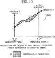
- Fig. 10is a conceptual diagram illustrating intra prediction encoding according to this embodiment.
- a pixel located at a boundary of a target blockis used as a new reference pixel (reference pixel 2) such that that prediction is performed in combination with a usual reference pixel (reference pixel 1).
- reference pixel 2two reference pixels (the reference pixel 1 and the reference pixel 2), both of which are located on a straight line passing through the target block, are selected.
- a value of a pixel located between these reference pixelsis then predicted by interpolation processing based on interpolative prediction that uses the two reference pixels. This makes it possible to increase the prediction accuracy particularly for a block whose luminance gradient is steep and to reduce the number of prediction errors.
- the reference pixel 1 and the reference pixel 2can be selected from among encoded pixels, they are selected from among the encoded pixels.
- the reference pixel 2is predicted from the encoded pixels in advance. After that, as shown in Fig. 10 , the prediction is performed by the interpolation processing based on the interpolative prediction that uses the two reference pixels.
- the prediction accuracy for a block whose luminance gradient is steepcan be increased, and accordingly, the number of prediction errors can be reduced.
- Fig. 4is a diagram conceptually illustrating an operation example of intra prediction encoding processing according to this embodiment.
- a target image to be encodedis encoded in the order of raster scanning, and the prediction is performed by referring to encoded blocks that are adjacent to a target block on the left, upper left, upper, and upper right sides of the target block.
- Reference numeral 401denotes intra prediction encoding steps in a vertical direction.
- predictionis executed by two steps as follows: a step 1 - prediction of a pixel located at a boundary of a target block (for example, a reference pixel 2 in (1001)) and the calculation of the difference in prediction; and a step 2 - bidirectional prediction using reference pixels located at both ends of a target block.
- two reference pixels used for the bidirectional predictionare selected.
- the reference pixelis predicted based on surrounding encoded blocks.
- values E, F, G, H of pixels located in the lowermost row of a target blockare predicted by an average value Z of four decoded pixels A', B', C', D' located in the same row of a block that is adjacent to the target block on the left side of the target block.
- difference values of the difference between Z and the four pixelsare encoded as difference in prediction values e, f, g, h respectively.
- step 2other pixel values included in the target block are predicted by performing interpolation processing based on the interpolative prediction that uses the two reference pixels selected or predicted in the step 1. For example, with reference to reference numeral 403, pixels J, K, L each belonging to the same column in the target block are predicted by linear interpolation that uses a reference pixel I' and a value of Z predicted in the step 1, and thereby difference in prediction values j, k, l are calculated. Moreover, these difference in prediction values are encoded.
- Fig. 7is a diagram conceptually illustrating an operation example of intra prediction decoding processing according to this embodiment.
- Decodingcan be made by executing steps reverse to those shown in Fig. 4 (701).
- an adjacent block located on the left side of the target blockis used to calculate the reference pixel Z (702), and the reference pixel Z is then added to the difference in prediction values e', f', g', h' of pixels located at the boundary of the target block so as to acquire decoded images E', F', G', H' respectively.
- each pixel included in the target blockis predicted (703) by the reference pixel I' included in an adjacent block located on the upper side of the target block, and by the linear interpolation based on the interpolative prediction of the value Z predicted by the above processing.
- Each predicted pixelis then added to difference in prediction values j', k', l' to acquire decoded pixels J', K ', L' respectively.
- the method according to the present applicationcannot be applied to blocks located at the end of a screen because the adjacent blocks located on the left and upper sides of the target pixel are used to predict one of the reference pixels. Accordingly, the bidirectional prediction according to this embodiment can be applied to the blocks located at the end of the screen by performing intra prediction encoding, for example, according to steps shown in Fig. 5 (501).
- the extrapolative predictionis performed by use of decoded values A', D' of two pixels located at both ends of an adjacent block located on the upper side of the target block to predict a pixel H located at a boundary of the same column included in the target block. Then the difference h between a pixel value H and a predicted value Z is encoded as the difference in prediction (502).
- pixels E, F, G each belonging to the same column in the target blockare predicted by performing linear interpolation based on the interpolative prediction that uses Z predicted in the step 1 as well as the reference pixel D', and then difference in prediction values e, f, g are encoded (503). That is, the step 1 of the intra prediction processing used for blocks located at the end of the screen differs in comparison with the other cases (shown in Fig. 4 ).
- the bidirectional prediction according to this embodimentcan be achieved by using the above step for the blocks located at the end of the screen.
- decodingcan be performed by use of steps shown in Fig. 8 .
- decodingcan be made by executing steps reverse to those shown in Fig. 5 (801).
- an adjacent block located on the upper side of the target blockis used to calculate the reference pixel Z (802), and the reference pixel Z is then added to a difference in prediction value h' of a pixel located at the boundary of the target block so as to acquire a decoded image H.
- each pixel included in the target blockis predicted (903) by the reference pixel D' included in an adjacent block located on the upper side of the target block, and by the linear interpolation using the value Z predicted by the above processing.
- Each predicted pixelis then added to difference in prediction values e', f', g' to acquire decoded pixels E', F', G' respectively.
- a prediction methodcan be selected from among a plurality of candidates.
- one of eight kinds of prediction directions other than DC predictioncan be selected from among nine prediction methods (1101) used in the H.264/AVC standards shown in Fig. 11 .
- prediction direction 1when prediction is performed in a horizontal direction (prediction direction 1) (1102), for blocks other than blocks located at the end of a screen, a pixel belonging to the rightmost column of a target block is predicted by use of an adjacent block located on the upper side of the target block. The predicted pixel is then used as one of reference pixels to perform the bidirectional prediction.
- a pixel belonging to the rightmost column of the target block, and a pixel belonging to the lowermost line of the target blockare predicted from adjacent blocks located on the upper and left sides of the target block respectively so as to achieve the bidirectional prediction.
- a prediction direction 4(1103)
- an adjacent block located on the left side of the target blockis used to predict a pixel value belonging to the leftmost column of the target block so as to achieve the bidirectional prediction.
- a prediction direction 7 (1105)an adjacent block located on the upper side of the target block is used to predict a pixel value belonging to the lowermost column of the target block so as to achieve the bidirectional prediction.
- the use of the steps of (1104) and (1105)makes it possible to achieve the bidirectional prediction according to this embodiment.
- a high compression ratiocan be achieved in response to characteristics of an image.
- encoding which is suitable for characteristics of the imagecan be made by appropriately using, on a block basis, the technique according to the present invention and the conventional techniques in performing encoding prediction.
- the conventional techniques which are effectiveinclude, for example, the intra prediction encoding method (decoding method) based on the H.264/AVC standards shown in Fig. 3 ( Fig. 6 ), and the inter prediction method that is also used in the H.264/AVC standards (prediction method referring to an image that differs from a target image to be encoded).
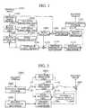
- Fig. 1is a diagram illustrating one embodiment of a moving image encoding apparatus according to the present invention.
- the moving image encoding apparatusincludes: an input image memory 102 for storing an inputted original image 101; a block dividing unit 103 for dividing an input image into small areas; and a motion estimating unit 104 for detecting motion on a block basis.
- the moving image encoding apparatusfurther includes: an old intra prediction unit 105 for performing intra prediction processing on a block basis according to steps other than those of this embodiment (for example, according to the intra prediction based on the H.264/AVC standards (shown in Fig. 3 )); a new intra prediction unit 106 for performing intra prediction according to this embodiment on a block basis (shown in Figs.
- the moving image encoding apparatusfurther includes: a mode selector 108 for determining prediction encoding means (a prediction method and the block size) that suit characteristics of an image; a subtraction unit 109 for calculating difference in prediction; a frequency converter 110 and a quantization unit 111 that encode the difference in prediction; a variable-length encoding unit 112 for performing encoding according to the probability of occurrence of a symbol; a reverse quantization processor 113 and a reverse frequency converter 114 that decode the difference in prediction which has been encoded; an adder 115 for generating a decoded image by use of the decoded difference in prediction; and a reference image memory 116 for storing a decoded image so that the decoded image is used for the prediction thereafter.
- a mode selector 108for determining prediction encoding means (a prediction method and the block size) that suit characteristics of an image
- a subtraction unit 109for calculating difference in prediction
- a frequency converter 110 and a quantization unit 111that encode the difference
- the input image memory 102stores, as a target image to be encoded, one image selected from among original images 101.
- the target imageis divided into small blocks by the block dividing unit 103.
- the small blocksare then sent to the motion estimating unit 104, the old intra prediction unit 105, and the new intra prediction unit 106.
- the motion estimating unit 104calculates the amount of motion of a particular block by use of a decoded image stored in the reference image memory 116, and then sends the calculated amount of motion to the inter prediction unit 107 as a motion vector.
- the old intra prediction unit 105, the new intra prediction unit 106, and the inter prediction unit 107executes intra prediction processing and inter prediction processing on a block basis using several kinds of block size.
- the mode selector 108selects the most suitable prediction encoding means.
- the subtraction unit 109generates the difference in prediction from the output by the most suitable prediction encoding means, and then sends the difference in prediction to the frequency converter 110.
- the frequency converter 110 and the quantization processor 111perform, on a block basis using the specified block size, the frequency conversion and quantization processing (for example, DCT (Discrete Cosine Transformation)) for the difference in prediction that has been sent.
- the result of the frequency conversion and quantization processingis sent to the variable-length encoding unit 112 and the reverse quantization processor 113.
- variable-length encoding unit 112not only information about the difference in prediction, which is expressed by a frequency conversion coefficient, but also information required for prediction encoding (including, for example, a prediction direction in intra prediction encoding, and a motion vector in inter prediction encoding), is subjected to variable-length encoding on the basis of the probability of occurrence of a symbol so that an encoded stream is generated.
- a frequency conversion coefficient subjected to quantizationundergoes reverse frequency conversion such as reverse quantization and IDCT (Inverse DCT) such that the difference in prediction is acquired.
- the difference in predictionis then transmitted to the adder 115.
- the adder 115generates a decoded image, which is then stored in the reference image memory 116.
- Fig. 2is a diagram illustrating one embodiment of a moving image decoding apparatus according to the present invention.
- the moving image decoding apparatusincludes: a variable-length decoder 202 for, according to steps reverse to those of the variable-length encoding, performing decoding of an encoded stream 201 generated by, for example, the moving image encoding apparatus shown in Fig. 1 ; and a reverse quantization processor 203 and a reverse frequency converter 204 that decode the difference in prediction.
- the moving image decoding apparatusfurther includes: an old intra prediction unit 205 for performing intra prediction processing according to steps other than those of this embodiment (for example, according to the intra prediction based on the H.264/AVC standards (shown in Fig.
- a new intra prediction unit 206for performing intra prediction according to this embodiment (shown in Figs. 7 , 8 ); an inter prediction unit 207 for performing intra prediction; an adder 208 for acquiring a decoded image; and a reference image memory 209 for temporarily storing the decoded image.
- the variable-length decoder 202decodes a encoded stream 201 in variable-length to acquire a frequency conversion coefficient component of the difference in prediction, and information required for prediction processing including a prediction direction or a motion vector.
- the formerwhich is the information about the difference in prediction
- the latterwhich is the information required for the prediction processing, is transmitted to the old intra prediction unit 205, the new intra prediction unit 206, or the inter prediction unit 207 in response to prediction means.
- the reverse quantization processor 203 and the reverse frequency converter 204the information about the difference in prediction is subjected to reverse quantization and reverse frequency conversion respectively such that the information about the difference in prediction is decoded.
- the prediction processingis executed with reference to the reference image memory 209 on the basis of information transmitted from the variable-length decoder 202 to allow the adder 208 to generate a decoded image, which is then stored in the reference image memory 209.
- Fig. 12is a flowchart illustrating how to encode one frame by the encode processing of the moving image encoding apparatus shown in Fig. 1 according to the embodiment of the present invention.
- all blocks existing in a target frame to be encoded(step 1201) are subjected to the following processing.
- each blockis subjected to prediction encoding processing in each of all encoding modes (that is to say, a combination of a prediction method and the block size) beforehand to calculate the difference in prediction.
- a block whose encoding efficiency is the highestis selected from among the calculated values of the difference in prediction.
- a prediction processing methodwill be described as below.
- step 1205new intra prediction encoding processing
- step 1206the intra prediction method adopted in the H.264/AVC standards
- step 1207inter prediction encoding processing
- the RD-Optimization methodis used to determine the most suitable encoding mode on the basis of, for example, the relationship between the distortion in image quality and the encoding amount. If the RD-Optimization method is used, for example, the method is applicable that is disclosed in G, Sullivan and T. Wiegand: "Rate-Distortion Optimization for Video Compression", IEEE Signal Processing Magazine, vol, 15, no.6, pp, 74-90, 1998 .
- the difference in prediction generated in the selected encoding modeis subjected to the frequency conversion (209) and the quantization processing (1210), and is then subjected to variable-length encoding so as to generate an encoded stream (step 1211).
- a frequency conversion coefficient subjected to quantizationundergoes reverse quantization processing (step 1212) and reverse frequency conversion processing (step 1213) to decode the difference in prediction such that a decoded image is generated.
- the decoded imageis then stored in the reference image memory (step 1214). If all blocks have been subjected to the above processing, encoding of one image frame ends (step 1215).
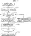
- Fig. 13is a flowchart illustrating in detail the new intra prediction encoding processing (the step 1205).
- the following processingis performed for all prediction directions defined beforehand (step 1301), and is performed for all lines in each prediction direction (step 1302).
- step 1303if a target block is located at the end of a screen (step 1303), a boundary pixel is predicted, and the difference in prediction is calculated, according to the step 1 shown in Fig. 5 (step 1304).
- the target blockis not located at the end of the screen, a boundary pixel is predicted, and the difference in prediction is calculated, according to the step 1 shown in Fig. 4 (step 1305).
- bidirectional predictionis performed according to the step 2 shown in Figs. 4 and 5 (step 1305). If the above processing for all prediction directions and all lines is completed, the prediction encoding processing for one block ends (step 1307).
- Fig. 14is a flowchart illustrating how to decode one frame by the decode processing of the moving image decoding apparatus shown in Fig. 2 according to the embodiment of the present invention.
- all blocks included in one frameare subjected to the following processing (step 1401).
- an input streamis subjected to variable-length decoding processing (step 1402), reverse quantization processing (step 1403), and reverse frequency conversion processing (step 1404) such that the difference in prediction is decoded.
- step 1407new intra prediction decoding processing
- old intra prediction decoding processingstep 1408)
- inter prediction decoding processingstep 1409 is executed to acquire a decoded image.
- the acquired decoded imageis then stored in the reference image memory. If all blocks included in the one frame have been completely subjected to the above processing, decoding for the one image frame ends (step 1410).
- Fig. 15is a flowchart illustrating in detail the new intra prediction decoding processing (the step 1407).
- all lines in a prediction directionare subjected to the following processing (step 1501).
- step 1501if a target block is located at the end of a screen (step 1402), a boundary pixel is predicted, and the difference in prediction is calculated, according to the step 1 shown in Fig. 8 (step 1403).
- step 1404if the target block is not located at the end of the screen, a boundary pixel is predicted, and the difference in prediction is calculated, according to the step 1 shown in Fig. 7 (step 1404).
- bidirectional predictionis performed according to the step 2 shown in Figs. 7 and 8 (step 1405). If all lines have been completely subjected to the above processing, the prediction encoding processing for one block ends (step 1406).
- DCTis taken as an example of the frequency conversion.
- any orthogonal transformation used for elimination of correlation between pixelsmay also be adopted (for example, DST (Discrete Sine Transformation), WT (Wavelet Transformation), DFT (Discrete Fourier Transformation), or KLT (Karhunen-Loeve Transformation)).
- the difference in prediction itselfmay also be encoded without performing the frequency conversion.
- the execution of variable-length encodingis not particularly required.
- this embodimentdescribes the case where luminance components are predicted particularly on a block (4x4 pixel size) basis. However, this embodiment may also be applied to any size block (for example, 8x8 pixel size, and 16x16 pixel size).
- this embodimentmay also be applied not only to the prediction of luminance components, but also to the prediction of color difference components Furthermore, according to this embodiment, the prediction is performed in eight directions that are specified in the H.264/AVC standards. However, the number of directions may also be increased or decreased.
- a prediction equation in this embodimentwill be described.
- a case where luminance components are predicted on a 4x4-pixel-size block basiswill be described.
- Fig. 16(1601)
- x axisis set on the right side in the horizontal direction
- y axisis set on the lower side in the vertical direction.
- a luminance value at coordinates (x, y) in a target blockis expressed as P [x, y]
- a predicted valueis expressed as pred4x4 [x, y].
- two reference pixels used for the bidirectional predictionare expressed as Ref1, Ref2 respectively.
- a function Min (a, b)returns a smaller one of two integers a, b
- a function ROUND (a)returns an integer value obtained by rounding off the first decimal place of a real number a.
- prediction of pixels which cannot be selected from encoded (decoded) pixelsis mainly performed by an average value of pixels belonging to the same row (or the same column) of encoded adjacent blocks.
- the above-described predictiondoes not need always the average value.
- a minimum value, a maximum value, and a median valuemay also be used.
- any kind of calculating formulafor example, extrapolative prediction (or interpolative prediction) using these pixels may also be used.
- any kind of methodfor example, linear interpolation, and nonlinear interpolation
- any kind of modelfor example, straight line/parabola approximation using the least-squares method, the Newton's interpolation, and the Lagrange interpolation
- Fig. 17is a conceptual diagram illustrating a case where the boundary pixels E, F, G, H are predicted by the extrapolative prediction in the step 1 (402) shown in Fig. 4 .
- a horizontal axisindicates coordinates
- a vertical axisindicates a luminance value.
- Reference numeral 1701shows a case where the straight-line approximation is performed.
- a predicted straight rowis calculated based on, for example, the least-squares method by using decoded pixels A', B', C', D' located in the lowermost line of an adjacent block located on the left side. Points corresponding to coordinates of boundary pixels E, F, G, H in the straight line are used as predicted values.
- reference numeral 1702shows a case where the same extrapolative prediction is performed by curve approximation including the parabola approximation, the Newton's interpolation, and the Lagrange interpolation.
- boundary pixels E, F, G, Hare predicted on the basis of a predicted curve calculated by use of decoded pixels A', B', C', D'.
- the boundary pixels predicted by the above processingare used as one of reference pixels, for example, when bidirectional prediction in the step 2 shown in Fig. 4 is performed.
- information used for the prediction of reference pixelsis not particularly limited to pixels belonging to the same row (or column) so long as it is information about adjacent blocks.
- the bidirectional prediction(for example, prediction of pixels J, K, L in the step 2 shown in Fig. 4 ) is performed by the linear interpolation that uses two reference pixels.
- the interpolation method thereofis not particularly limited so long as a target pixel is located between the two reference pixels to be used.
- a predicted value of the target pixelmay also be expressed by any straight-line equation of two reference pixels.
- each of a, brepresents a constant that is a real number. These values may also be defined as predetermined values, or may also be specified on a block basis.
- blocks to which the intra prediction encoding method (decoding method) used for the screen end shown in Fig. 5 ( Fig. 8 ) can be appliedare not particularly limited to blocks located at the screen end. In other words, this method may also be applied to blocks other than the blocks located at the screen end.
- Fig. 18is a diagram illustrating a configuration example of an encoded stream generated according to this embodiment, the diagram mainly showing encoding parameters that should be set on a block basis.
- an encoding modeis determined on a fixed-length macro block basis.
- Each macro blockcan be further divided into smaller blocks.
- Prediction encodingshall be performed on a divided block basis.
- informationis encoded in variable-length, and is then stored.
- the information to be subjected to encodingincludes: a macro block number (1801) used to identify coordinates on a macro block basis; an encoding mode number (1802) that indicates a prediction method and the block size; information required for prediction (1803) including, for example, a motion vector at the time of inter prediction, and a prediction direction at the time of intra prediction; and information about difference in prediction (1804).
- the encoding mode number (1802)may also be serially assigned to all prediction means, or may also be expressed with different bits on a prediction means basis.
- Fig. 19is a diagram illustrating another configuration example of an encoded stream generated according to this embodiment shown in Fig. 18 , the diagram mainly showing encoding parameters that should be set on a block basis.
- This configuration exampleincludes: a macro block number (1901); a prediction method (1902); a flag (1903) indicating whether or not to perform prediction using an adjacent pixel according to this embodiment; informational required for prediction (1904); and information about difference in prediction (1905).
Landscapes
- Engineering & Computer Science (AREA)
- Multimedia (AREA)
- Signal Processing (AREA)
- Compression Or Coding Systems Of Tv Signals (AREA)
Description
- The present invention relates to moving image encoding techniques for encoding a moving image.
- Encoding methods including MPEG (Moving Picture Experts Group) method have been drafted as techniques for converting a large amount of moving image information into digital data to write and transfer the digital data. Such encoding methods include MPEG-1 standards, MPEG-2 standards, MPEG-4 standards, and H.264/AVC (Advanced Video Coding) standards and are used as international standard encoding methods.
- According to the above-described standards, information about an image whose encoding processing has been completed is used to predict, on a block basis, a target image to be encoded. Then, by encoding the difference in prediction between the target image and an original image, the redundancy of the moving image is eliminated to reduce the encoding amount. In particular, according to the H.264/AVC standards, a drastic improvement in compression ratio is achieved by adopting the intra prediction encoding method that uses pixels surrounding a target block to be encoded.
- However, when the intra prediction according to the H.264/AVC standards is executed, a prediction method thereof is too simple to achieve the sufficient prediction accuracy. For example, the intra prediction based on the H.264/AVC standards adopts a unidirectional prediction method in which only one reference pixel is specified so that all pixels in a prediction direction are predicted by use of a pixel value of only one reference pixel as a reference value. Accordingly, there was room for an improvement in prediction accuracy. Therefore, an intra encoding technique, which is capable of improving the accuracy of intra prediction to increase a compression ratio, is required.
- As a technique for improving the accuracy in intra prediction, for example,
JP-A-2006-352181 - In addition,
nonpatent literature 1 discloses a technique in which prediction is performed by use of blocks existing on the upper and lower and right and left sides by changing the order of encoding on a block basis. - Nonpatent literature 1: "Block Based Extra/Interpolating Prediction for Intra Coding" T. Shiodera, A. Tanizawa, T. Chujoh, PCSJ2006, November, 2006.
- However, according to
JP-A-2006-352181 - In addition, according to the
nonpatent literature 1, the number of blocks, each of which can be predicted by use of blocks existing on the upper and lower and right and left sides, is limited. Therefore, the prediction accuracy of blocks other than these predictable blocks decreases in comparison with that in the case of the H.264/AVC standards. US2007/110153 discloses a method, medium, and apparatus encoding and/or decoding an image in order to increase encoding and decoding efficiency by performing binary-arithmetic coding/decoding on a binary value of a syntax element using a probability model having the same syntax element probability value for respective context index information of each of at least two image components.US2007/121731 discloses an image coding method that includes dividing an input picture into a plurality of pixel block signals, performing intra prediction for extrapolating or interpolating a prediction pixel using reference pixels changed in number according to a distance between the prediction pixel and a reference pixel in plural prediction modes each representing a prediction direction, generating a predictive image signal by extrapolating or interpolating the prediction pixel, calculating a prediction error signal from the pixel block signal and the predictive image signal, selecting one prediction mode of the plural prediction modes using the prediction error signal, and performing entropy-coding using the prediction error signal based on the selected prediction mode.- PENG ZHANG ET AL: "Multiple modes intra-prediction in intra coding", 2004 IEEE INTERNATIONAL CONFERENCE ON MUL TI MEDIA AND EXPO (ICME) (IEEE CAT. N0.04TH8763) IEEE PISCATAWAY, NJ, USA, vol. 1, 27 June 2004 (2004-06-27), pages 419-422, XP010770800, ISBN: 978-0-7803-8603-7, proposes a multiple mode intra prediction scheme to achieve a better balance between prediction precision and side information cost. Three kinds of additional modes are described that aim to increase prediction precision from different aspects. It says that a significant performance gain can be achieved using this multiple modes intra-prediction while with little complexity increase.
- The problem with the above conventional techniques is that, for example, when a luminance value largely changes in a prediction direction, the difference in predicted value becomes larger, which causes the encoding amount to increase, resulting in a reduction in compression ratio.
- The present invention has been made taking the above-described problem into consideration, and a preferred aim of the present invention is to provide an image encoding/decoding technique that is capable of achieving the higher compression efficiency.
- According to the present invention there is provided an image decoding method according to
claim 1. - These and other features, objects and advantages of the present invention will become apparent from the
following description when taken in conjunction with the accompanying drawings wherein: Fig. 1 is a diagram illustrating an image encoding apparatus according to one embodiment of the present invention;Fig. 2 is a diagram illustrating an image decoding apparatus according to one embodiment of the present invention;Fig. 3 is a diagram illustrating intra prediction encoding processing used in the H.264/AVC standards;Fig. 4 is a diagram illustrating intra prediction encoding processing according to one embodiment of the present invention;Fig. 5 is a diagram illustrating intra prediction encoding processing according to one embodiment of the present invention;Fig. 6 is a diagram illustrating intra prediction decoding processing used in the H.264/AVC standards;Fig. 7 is a diagram illustrating intra prediction decoding processing according to one embodiment of the present invention;Fig. 8 is a diagram illustrating intra prediction decoding processing according to one embodiment of the present invention;Fig. 9 is a diagram illustrating intra prediction used in the H.264/AVC standards;Fig. 10 is a diagram illustrating intra prediction according to one embodiment of the present invention;Fig. 11 is a diagram illustrating intra prediction according to one embodiment of the present invention;Fig. 12 is a flowchart illustrating an image encoding apparatus according to one embodiment of the present invention;Fig. 13 is a flowchart illustrating in detail an image encoding apparatus according to one embodiment of the present invention;Fig. 14 is a flowchart illustrating an image decoding apparatus according to one embodiment of the present invention;Fig. 15 is a flowchart illustrating in detail an image decoding apparatus according to one embodiment of the present invention;Fig. 16 is a diagram illustrating one embodiment of the present invention;Fig. 17 is a diagram illustrating a prediction method that differs from the intra prediction according to one embodiment of the present invention;Fig. 18 is a diagram illustrating a configuration example of an encoded stream according to one embodiment of the present invention; andFig. 19 is a diagram illustrating a configuration example of an encoded stream according to one embodiment of the present invention.- Embodiments of the present invention will be described below with reference to the accompanying drawings.
- Each element designated by the same reference numeral in the drawings has substantially the same function.
"the sum of pixels" in the description and drawings of this specification expresses a result obtained by adding pixel values. - First of all, the operation of intra prediction encoding processing based on the H.264/AVC standards will be described with reference to
Fig. 3 . In the case of the H.264/AVC standards, a target image to be encoded is encoded in the order of raster scanning (301). Incidentally, in general, the order of raster scanning means that processing is performed from the top left end of a screen to the right end, and then the processing is performed from the bottom left end of the screen to the right end, and this series of processing is repeated. - Here, each pixel of a target block to be encoded is predicted by using a pixel value of a decoded image in each of encoded blocks that are adjacent to the target block to be encoded on the left, upper left, upper, and upper right sides of the target block.
- In particular, a pixel value of one pixel selected from among 13 pixels in the encoded blocks shown in
Fig. 3 is used as a reference value. All pixels which are in alignment with the same straight line in a prediction direction from the one pixel (a start point) are predicted by referring to the pixel value of the one pixel as the reference value (302). - For example, as shown with
reference numeral 303, all of pixels B, C, D, E of the target block to be encoded are subjected to prediction encoding with reference to the same pixel. Next, difference values (difference in prediction) b, c, d, e from a value A', which has been obtained by decoding a pixel directly above the pixel B, are calculated. Moreover, in the case of the H.264/AVC standards, the most suitable prediction direction candidate can be selected from among eight kinds of prediction direction candidates (for example, vertical, horizontal, and diagonal) on a block basis, so that value of the difference in prediction, and a value of the prediction direction are encoded. It should be noted that, according to the H.264/AVC standards, it is possible to use "DC prediction" that predicts all pixels included in a target block to be encoded on the basis of an average value of reference pixels (304) in addition to the prediction in the specific direction. - Next, the operation of intra prediction decoding processing based on the H.264/AVC standards will be described with reference to
Fig. 6 . Similar to the encoding processing, decoding processing is also executed in the order of raster scanning (601). A pixel value of a decoded image is calculated by use of a decoded reference pixel and the difference in prediction. To be more specific, a decoded image is acquired by adding the difference in prediction to the reference pixel in a prediction direction. - For example, in
reference numeral 602, by adding difference in prediction values b', c', d', e' of a target block to be decoded (values obtained by decoding b, c, d, e shown inFig. 3 respectively, the values including a quantization error) to the decoded reference pixel A' respectively, decoded pixels B', C', D', E' (decoded pixels for B, C, D, E shown inFig. 3 ) are acquired respectively. - As described above, the intra prediction encoding processing based on the H.264/AVC adopts a simple unidirectional method in which only one reference pixel is specified to predict all pixels in a prediction direction by a value of the reference pixel.
Fig. 9 is a conceptual diagram illustrating intra prediction encoding based on the H.264/AVC standards. Here, a horizontal axis indicates coordinate values in a target block in a prediction direction; and a vertical axis indicates a pixel value (luminance value) in the coordinates. Accordingly, a curve in a graph expresses a luminance curve in a target block. As previously described, according to the H.264/AVC standards, blocks which can be referred to when intra prediction is performed are limited to blocks located on the left and upper sides of a target block. The H.264/AVC standards, therefore, adopt a method in which a reference pixel is copied in one direction. In this case, as indicated withreference numeral 901, if a luminance gradient in the target block is gentle, there is a higher possibility that prediction will come true. Accordingly, the difference in prediction decreases. However, as indicated with reference numeral 902, if the luminance gradient is steep, the difference in prediction increases with the increase in distance from the reference pixel, which results in an increase in the encoding amount.Fig. 10 is a conceptual diagram illustrating intra prediction encoding according to this embodiment. In order to solve the above problem accompanied by the H.264/AVC standards, in this embodiment, as indicated withreference numeral 1001, a pixel located at a boundary of a target block is used as a new reference pixel (reference pixel 2) such that that prediction is performed in combination with a usual reference pixel (reference pixel 1). Specifically, two reference pixels (thereference pixel 1 and the reference pixel 2), both of which are located on a straight line passing through the target block, are selected. A value of a pixel located between these reference pixels is then predicted by interpolation processing based on interpolative prediction that uses the two reference pixels. This makes it possible to increase the prediction accuracy particularly for a block whose luminance gradient is steep and to reduce the number of prediction errors.- However, similar to the H.264/AVC standards, if encoding is performed in the order of raster scanning, in many cases a value of only one (reference pixel 1) of two reference pixels located at a boundary of a target block can be acquired. For this reason, the method according to the present application predicts a value of the other reference pixel (reference pixel 2) from a pixel value included in a surrounding encoded block.
- To be more specific, according to this embodiment, if the
reference pixel 1 and thereference pixel 2 can be selected from among encoded pixels, they are selected from among the encoded pixels. Here, if thereference pixel 2 cannot be selected from among the encoded pixels, thereference pixel 2 is predicted from the encoded pixels in advance. After that, as shown inFig. 10 , the prediction is performed by the interpolation processing based on the interpolative prediction that uses the two reference pixels. - As a result, even if one of the two reference pixels is not an encoded pixel, the prediction accuracy for a block whose luminance gradient is steep can be increased, and accordingly, the number of prediction errors can be reduced.
Fig. 4 is a diagram conceptually illustrating an operation example of intra prediction encoding processing according to this embodiment. Also in this case, a target image to be encoded is encoded in the order of raster scanning, and the prediction is performed by referring to encoded blocks that are adjacent to a target block on the left, upper left, upper, and upper right sides of the target block.Reference numeral 401 denotes intra prediction encoding steps in a vertical direction. Here, prediction is executed by two steps as follows: a step 1 - prediction of a pixel located at a boundary of a target block (for example, areference pixel 2 in (1001)) and the calculation of the difference in prediction; and a step 2 - bidirectional prediction using reference pixels located at both ends of a target block.- In the
step 1, two reference pixels used for the bidirectional prediction are selected. Here, if a reference pixel cannot be selected from among encoded pixels, the reference pixel is predicted based on surrounding encoded blocks. For example, with reference to reference numeral 402, values E, F, G, H of pixels located in the lowermost row of a target block are predicted by an average value Z of four decoded pixels A', B', C', D' located in the same row of a block that is adjacent to the target block on the left side of the target block. Concurrently, difference values of the difference between Z and the four pixels are encoded as difference in prediction values e, f, g, h respectively. - Next, in the
step 2, other pixel values included in the target block are predicted by performing interpolation processing based on the interpolative prediction that uses the two reference pixels selected or predicted in thestep 1. For example, with reference toreference numeral 403, pixels J, K, L each belonging to the same column in the target block are predicted by linear interpolation that uses a reference pixel I' and a value of Z predicted in thestep 1,and thereby difference in prediction values j, k, l are calculated. Moreover, these difference in prediction values are encoded. Fig. 7 is a diagram conceptually illustrating an operation example of intra prediction decoding processing according to this embodiment. Decoding can be made by executing steps reverse to those shown inFig. 4 (701). First of all, an adjacent block located on the left side of the target block is used to calculate the reference pixel Z (702), and the reference pixel Z is then added to the difference in prediction values e', f', g', h' of pixels located at the boundary of the target block so as to acquire decoded images E', F', G', H' respectively. Subsequently, each pixel included in the target block is predicted (703) by the reference pixel I' included in an adjacent block located on the upper side of the target block, and by the linear interpolation based on the interpolative prediction of the value Z predicted by the above processing. Each predicted pixel is then added to difference in prediction values j', k', l' to acquire decoded pixels J', K ', L' respectively.- In the case of the intra prediction shown in
Fig. 4 , the method according to the present application cannot be applied to blocks located at the end of a screen because the adjacent blocks located on the left and upper sides of the target pixel are used to predict one of the reference pixels. Accordingly, the bidirectional prediction according to this embodiment can be applied to the blocks located at the end of the screen by performing intra prediction encoding, for example, according to steps shown inFig. 5 (501). To be more specific, in the step 1 (the prediction of pixels located at the boundary of the target block, and the calculation of the difference in prediction), the extrapolative prediction is performed by use of decoded values A', D' of two pixels located at both ends of an adjacent block located on the upper side of the target block to predict a pixel H located at a boundary of the same column included in the target block. Then the difference h between a pixel value H and a predicted value Z is encoded as the difference in prediction (502). - Next, in the step 2 (the bidirectional prediction using reference pixels located at both ends of the target block.), pixels E, F, G each belonging to the same column in the target block are predicted by performing linear interpolation based on the interpolative prediction that uses Z predicted in the
step 1 as well as the reference pixel D', and then difference in prediction values e, f, g are encoded (503). That is, thestep 1 of the intra prediction processing used for blocks located at the end of the screen differs in comparison with the other cases (shown inFig. 4 ). - Even if an adjacent block located on the left side of the target block cannot be used, the bidirectional prediction according to this embodiment can be achieved by using the above step for the blocks located at the end of the screen. In this case, decoding can be performed by use of steps shown in
Fig. 8 . To be more specific, decoding can be made by executing steps reverse to those shown inFig. 5 (801). First, an adjacent block located on the upper side of the target block is used to calculate the reference pixel Z (802), and the reference pixel Z is then added to a difference in prediction value h' of a pixel located at the boundary of the target block so as to acquire a decoded image H. Subsequently, each pixel included in the target block is predicted (903) by the reference pixel D' included in an adjacent block located on the upper side of the target block, and by the linear interpolation using the value Z predicted by the above processing. Each predicted pixel is then added to difference in prediction values e', f', g' to acquire decoded pixels E', F', G' respectively. - Even in the case of the method according to the present application, a prediction method can be selected from among a plurality of candidates. For example, one of eight kinds of prediction directions other than DC prediction can be selected from among nine prediction methods (1101) used in the H.264/AVC standards shown in
Fig. 11 . For example, when prediction is performed in a horizontal direction (prediction direction 1) (1102), for blocks other than blocks located at the end of a screen, a pixel belonging to the rightmost column of a target block is predicted by use of an adjacent block located on the upper side of the target block. The predicted pixel is then used as one of reference pixels to perform the bidirectional prediction. - In addition, when prediction is performed in a diagonal direction as indicated with a prediction direction 4 (1103), a pixel belonging to the rightmost column of the target block, and a pixel belonging to the lowermost line of the target block, are predicted from adjacent blocks located on the upper and left sides of the target block respectively so as to achieve the bidirectional prediction. On the other hand, for the blocks located at the end of the screen, for example, when prediction is performed in the horizontal direction (prediction direction 1) (1104), an adjacent block located on the left side of the target block is used to predict a pixel value belonging to the leftmost column of the target block so as to achieve the bidirectional prediction. Moreover, in the case of a prediction direction 7 (1105), an adjacent block located on the upper side of the target block is used to predict a pixel value belonging to the lowermost column of the target block so as to achieve the bidirectional prediction. In this case, even if adjacent blocks located on the upper and left sides cannot be used, the use of the steps of (1104) and (1105) makes it possible to achieve the bidirectional prediction according to this embodiment.
- If the prediction encoding technique according to this embodiment is used in combination with the conventional technologies, a high compression ratio can be achieved in response to characteristics of an image. For example, encoding which is suitable for characteristics of the image can be made by appropriately using, on a block basis, the technique according to the present invention and the conventional techniques in performing encoding prediction. The conventional techniques which are effective include, for example, the intra prediction encoding method (decoding method) based on the H.264/AVC standards shown in
Fig. 3 (Fig. 6 ), and the inter prediction method that is also used in the H.264/AVC standards (prediction method referring to an image that differs from a target image to be encoded). Fig. 1 is a diagram illustrating one embodiment of a moving image encoding apparatus according to the present invention. The moving image encoding apparatus includes: aninput image memory 102 for storing an inputtedoriginal image 101; ablock dividing unit 103 for dividing an input image into small areas; and amotion estimating unit 104 for detecting motion on a block basis. The moving image encoding apparatus further includes: an oldintra prediction unit 105 for performing intra prediction processing on a block basis according to steps other than those of this embodiment (for example, according to the intra prediction based on the H.264/AVC standards (shown inFig. 3 )); a newintra prediction unit 106 for performing intra prediction according to this embodiment on a block basis (shown inFigs. 4 ,5 ); and an inter prediction unit 107 for performing inter prediction on a block basis on the basis of the amount of motion estimated by the motion estimating unit 10.. The moving image encoding apparatus further includes: amode selector 108 for determining prediction encoding means (a prediction method and the block size) that suit characteristics of an image; asubtraction unit 109 for calculating difference in prediction; afrequency converter 110 and aquantization unit 111 that encode the difference in prediction; a variable-length encoding unit 112 for performing encoding according to the probability of occurrence of a symbol; areverse quantization processor 113 and areverse frequency converter 114 that decode the difference in prediction which has been encoded; anadder 115 for generating a decoded image by use of the decoded difference in prediction; and areference image memory 116 for storing a decoded image so that the decoded image is used for the prediction thereafter.- The
input image memory 102 stores, as a target image to be encoded, one image selected from amongoriginal images 101. The target image is divided into small blocks by theblock dividing unit 103. The small blocks are then sent to themotion estimating unit 104, the oldintra prediction unit 105, and the newintra prediction unit 106. Themotion estimating unit 104 calculates the amount of motion of a particular block by use of a decoded image stored in thereference image memory 116, and then sends the calculated amount of motion to the inter prediction unit 107 as a motion vector. The oldintra prediction unit 105, the newintra prediction unit 106, and the inter prediction unit 107 executes intra prediction processing and inter prediction processing on a block basis using several kinds of block size. Themode selector 108 selects the most suitable prediction encoding means. Next, thesubtraction unit 109 generates the difference in prediction from the output by the most suitable prediction encoding means, and then sends the difference in prediction to thefrequency converter 110. Thefrequency converter 110 and thequantization processor 111 perform, on a block basis using the specified block size, the frequency conversion and quantization processing (for example, DCT (Discrete Cosine Transformation)) for the difference in prediction that has been sent. The result of the frequency conversion and quantization processing is sent to the variable-length encoding unit 112 and thereverse quantization processor 113. Moreover, in the variable-length encoding unit 112, not only information about the difference in prediction, which is expressed by a frequency conversion coefficient, but also information required for prediction encoding (including, for example, a prediction direction in intra prediction encoding, and a motion vector in inter prediction encoding), is subjected to variable-length encoding on the basis of the probability of occurrence of a symbol so that an encoded stream is generated. - In addition, in the
reverse quantization processor 113 and thereverse frequency converter 114, a frequency conversion coefficient subjected to quantization undergoes reverse frequency conversion such as reverse quantization and IDCT (Inverse DCT) such that the difference in prediction is acquired. The difference in prediction is then transmitted to theadder 115. Next, theadder 115 generates a decoded image, which is then stored in thereference image memory 116. Fig. 2 is a diagram illustrating one embodiment of a moving image decoding apparatus according to the present invention. The moving image decoding apparatus includes: a variable-length decoder 202 for, according to steps reverse to those of the variable-length encoding, performing decoding of an encodedstream 201 generated by, for example, the moving image encoding apparatus shown inFig. 1 ; and areverse quantization processor 203 and areverse frequency converter 204 that decode the difference in prediction. The moving image decoding apparatus further includes: an oldintra prediction unit 205 for performing intra prediction processing according to steps other than those of this embodiment (for example, according to the intra prediction based on the H.264/AVC standards (shown inFig. 6 )); a newintra prediction unit 206 for performing intra prediction according to this embodiment (shown inFigs. 7 ,8 ); aninter prediction unit 207 for performing intra prediction; anadder 208 for acquiring a decoded image; and areference image memory 209 for temporarily storing the decoded image.- The variable-
length decoder 202 decodes a encodedstream 201 in variable-length to acquire a frequency conversion coefficient component of the difference in prediction, and information required for prediction processing including a prediction direction or a motion vector. The former, which is the information about the difference in prediction, is transmitted to thereverse quantization processor 203. The latter, which is the information required for the prediction processing, is transmitted to the oldintra prediction unit 205, the newintra prediction unit 206, or theinter prediction unit 207 in response to prediction means. Next, in thereverse quantization processor 203 and thereverse frequency converter 204, the information about the difference in prediction is subjected to reverse quantization and reverse frequency conversion respectively such that the information about the difference in prediction is decoded. On the other hand, in the oldintra prediction unit 205, the newintra prediction unit 206, or theinter prediction unit 206, the prediction processing is executed with reference to thereference image memory 209 on the basis of information transmitted from the variable-length decoder 202 to allow theadder 208 to generate a decoded image, which is then stored in thereference image memory 209. Fig. 12 is a flowchart illustrating how to encode one frame by the encode processing of the moving image encoding apparatus shown inFig. 1 according to the embodiment of the present invention. First, all blocks existing in a target frame to be encoded (step 1201) are subjected to the following processing. To be more specific, each block is subjected to prediction encoding processing in each of all encoding modes (that is to say, a combination of a prediction method and the block size) beforehand to calculate the difference in prediction. After that, a block whose encoding efficiency is the highest is selected from among the calculated values of the difference in prediction. A prediction processing method will be described as below. In addition to the method described in this embodiment (hereinafter referred to as "new intra prediction encoding processing" (step 1205)), for example, the intra prediction method adopted in the H.264/AVC standards (hereinafter referred to as "old intra prediction encode processing" (step 1206)), and inter prediction encoding processing (step 1207) are executed. By selecting the most suitable mode from among them, efficient encoding can be performed in response to characteristics of an image. When an encoding mode whose encoding efficiency is high is selected from among the large number of encoding modes described above (step 1208), the use of the RD-Optimization method enables efficient encoding. The RD-Optimization method is used to determine the most suitable encoding mode on the basis of, for example, the relationship between the distortion in image quality and the encoding amount. If the RD-Optimization method is used, for example, the method is applicable that is disclosed inG, Sullivan and T. Wiegand: "Rate-Distortion Optimization for Video Compression", IEEE Signal Processing Magazine, vol, 15, no.6, pp, 74-90, 1998.- Next, the difference in prediction generated in the selected encoding mode is subjected to the frequency conversion (209) and the quantization processing (1210), and is then subjected to variable-length encoding so as to generate an encoded stream (step 1211). In contrast, a frequency conversion coefficient subjected to quantization undergoes reverse quantization processing (step 1212) and reverse frequency conversion processing (step 1213) to decode the difference in prediction such that a decoded image is generated. The decoded image is then stored in the reference image memory (step 1214). If all blocks have been subjected to the above processing, encoding of one image frame ends (step 1215).
Fig. 13 is a flowchart illustrating in detail the new intra prediction encoding processing (the step 1205). Here, for example, as shown with thereference numeral 1101, the following processing is performed for all prediction directions defined beforehand (step 1301), and is performed for all lines in each prediction direction (step 1302). To be more specific, if a target block is located at the end of a screen (step 1303), a boundary pixel is predicted, and the difference in prediction is calculated, according to thestep 1 shown inFig. 5 (step 1304). In contrast, if the target block is not located at the end of the screen, a boundary pixel is predicted, and the difference in prediction is calculated, according to thestep 1 shown inFig. 4 (step 1305). Subsequently, based on values of reference pixels included in surrounding blocks and values of the boundary pixels predicted by the above steps, bidirectional prediction is performed according to thestep 2 shown inFigs. 4 and5 (step 1305). If the above processing for all prediction directions and all lines is completed, the prediction encoding processing for one block ends (step 1307).Fig. 14 is a flowchart illustrating how to decode one frame by the decode processing of the moving image decoding apparatus shown inFig. 2 according to the embodiment of the present invention. First, all blocks included in one frame are subjected to the following processing (step 1401). To be more specific, an input stream is subjected to variable-length decoding processing (step 1402), reverse quantization processing (step 1403), and reverse frequency conversion processing (step 1404) such that the difference in prediction is decoded. Subsequently, according to the method having subjected the target block to prediction encoding, new intra prediction decoding processing (step 1407), old intra prediction decoding processing (step 1408), or inter prediction decoding processing (step 1409) is executed to acquire a decoded image. The acquired decoded image is then stored in the reference image memory. If all blocks included in the one frame have been completely subjected to the above processing, decoding for the one image frame ends (step 1410).Fig. 15 is a flowchart illustrating in detail the new intra prediction decoding processing (the step 1407). Here, all lines in a prediction direction are subjected to the following processing (step 1501). To be more specific, if a target block is located at the end of a screen (step 1402), a boundary pixel is predicted, and the difference in prediction is calculated, according to thestep 1 shown inFig. 8 (step 1403). In contrast, if the target block is not located at the end of the screen, a boundary pixel is predicted, and the difference in prediction is calculated, according to thestep 1 shown inFig. 7 (step 1404). Subsequently, based on values of reference pixels included in surrounding blocks and values of the boundary pixels predicted by the above steps, bidirectional prediction is performed according to thestep 2 shown inFigs. 7 and8 (step 1405). If all lines have been completely subjected to the above processing, the prediction encoding processing for one block ends (step 1406).- In this embodiment, DCT is taken as an example of the frequency conversion. However, any orthogonal transformation used for elimination of correlation between pixels may also be adopted (for example, DST (Discrete Sine Transformation), WT (Wavelet Transformation), DFT (Discrete Fourier Transformation), or KLT (Karhunen-Loeve Transformation)). In particular, the difference in prediction itself may also be encoded without performing the frequency conversion. Moreover, the execution of variable-length encoding is not particularly required. In addition, this embodiment describes the case where luminance components are predicted particularly on a block (4x4 pixel size) basis. However, this embodiment may also be applied to any size block (for example, 8x8 pixel size, and 16x16 pixel size). Further, this embodiment may also be applied not only to the prediction of luminance components, but also to the prediction of color difference components Furthermore, according to this embodiment, the prediction is performed in eight directions that are specified in the H.264/AVC standards. However, the number of directions may also be increased or decreased.
- Next, an example of a prediction equation in this embodiment will be described. Here, a case where luminance components are predicted on a 4x4-pixel-size block basis will be described. First, as shown in
Fig. 16 (1601), on the assumption that coordinates of a pixel located at the upper leftmost of a target block are (0, 0), x axis is set on the right side in the horizontal direction, whereas y axis is set on the lower side in the vertical direction. Next, a luminance value at coordinates (x, y) in a target block is expressed as P [x, y]; and a predicted value is expressed as pred4x4 [x, y]. In addition, two reference pixels used for the bidirectional prediction are expressed as Ref1, Ref2 respectively. Incidentally, a function Min (a, b) returns a smaller one of two integers a, b; and a function ROUND (a) returns an integer value obtained by rounding off the first decimal place of a real number a. - Next, a case where prediction is performed in eight kinds of directions excluding DC prediction (1604) from among nine kinds of prediction methods (1602) through (1610) will be described using an equation of a predicted value pred4x4.
- When prediction is to be executed in a prediction direction 0 (Vertical) (1602), the prediction is performed by an
equation 1 as follows: - a case where adjacent blocks located on the left and the upper side can be used:


- a case where although an adjacent block located on the upper side can be used, an adjacent block located on the left side cannot be used:


- When prediction is to be executed in a prediction direction 1 (Horizontal) (1603), the prediction is performed by an
equation 2 as follows: - a case where adjacent blocks located on the left and the upper side can be used:


- a case where although an adjacent block located on the left side can be used, an adjacent block located on the upper side cannot be used:


- When prediction is to be executed in a prediction direction 3 (Diagonal Down Left) (1605), the prediction is performed by an
equation 3 as follows: - a case where adjacent blocks located on the left and the upper side can be used:
- when x = y = 3


- for the other cases (more specifically, x is not equivalent to 3, and y is not equivalent to 3)


- a case where although an adjacent block located on the upper side can be used, an adjacent block located on the left side cannot be used:
- when x = y = 3


- for the other cases (more specifically, x is not equivalent to 3, and y is not equivalent to 3)


- When prediction is to be executed in a prediction direction 4 (Diagonal Down Right) (1606), the prediction is performed by an
equation 4 as follows: - a case where adjacent blocks located on the left and the upper side can be used:
- when x >
y 


- when x <
y 


- when x =
y 


- When prediction is to be executed in a prediction direction 5 (Vertical Right) (1607), the prediction is performed by an
equation 5 as follows: - when zVR = 2*xy,
- a case where adjacent blocks located on the left and the upper side can be used:
- when zVR = 0, 2, 4, 6


- when zVR = 1, 3, 5


- when zVR = -1


- for the other cases (more specifically, zVR = -2, -3)


- When prediction is to be executed in a prediction direction 6 (Horizontal Down) (1608), the prediction is performed by an
equation 6 as follows: - when zHD = 2*yx,
- a case where adjacent blocks located on the left and the upper side can be used:
- when zHD = 0, 2, 4, 6


- when zHD = 1, 3, 5


- when zHD = -1


- for the other cases (more specifically, zHD = -2, -3)


- When prediction is to be executed in a prediction direction 7 (Vertical Left) (1609), the prediction is performed by an
equation 7 as follows: - a case where adjacent blocks located on the left and the upper side can be used:
- when y = 0, 2


- for the other cases (more specifically, y = 1, 3)


- a case where although an adjacent block located on the upper side can be used, an adjacent block located on the left side cannot be used:
- when y = 0, 2


- for the other cases (more specifically, y = 1, 3)


- When prediction is to be executed in a prediction direction 8 (Horizontal Up) (1610), the prediction is performed by an
equation 8 as follows: - when zHU = x+2*y,
- a case where adjacent blocks located on the left and the upper side can be used:
- when zHU = 0, 2, 4


- when zHU = 1, 3


- when zHU = 5


- for the other cases (more specifically, zHU > 5)


- a case where although an adjacent block located on the left side can be used, an adjacent block located on the upper side cannot be used:
- a case where zHU = 0, 2, 4


- when zHU = 1, 3


- when zHU = 5


- for the other cases (more specifically, zHU > 5)


- In the embodiment described above, when two reference pixels are used, prediction of pixels which cannot be selected from encoded (decoded) pixels (for example, prediction of boundary pixels E, F, G, H in the
step 1 shown inFig. 4 ) is mainly performed by an average value of pixels belonging to the same row (or the same column) of encoded adjacent blocks. However, the above-described prediction does not need always the average value. For example, a minimum value, a maximum value, and a median value may also be used. In addition, any kind of calculating formula (for example, extrapolative prediction (or interpolative prediction) using these pixels) may also be used. In particular, when the interpolative prediction is performed, any kind of method (for example, linear interpolation, and nonlinear interpolation) may also be used. On the other hand, when the extrapolative prediction is performed, any kind of model (for example, straight line/parabola approximation using the least-squares method, the Newton's interpolation, and the Lagrange interpolation) may also be used to perform the prediction. Fig. 17 is a conceptual diagram illustrating a case where the boundary pixels E, F, G, H are predicted by the extrapolative prediction in the step 1 (402) shown inFig. 4 . Here, a horizontal axis indicates coordinates, whereas a vertical axis indicates a luminance value.Reference numeral 1701 shows a case where the straight-line approximation is performed. A predicted straight row is calculated based on, for example, the least-squares method by using decoded pixels A', B', C', D' located in the lowermost line of an adjacent block located on the left side. Points corresponding to coordinates of boundary pixels E, F, G, H in the straight line are used as predicted values. In addition,reference numeral 1702 shows a case where the same extrapolative prediction is performed by curve approximation including the parabola approximation, the Newton's interpolation, and the Lagrange interpolation. In this case, boundary pixels E, F, G, H are predicted on the basis of a predicted curve calculated by use of decoded pixels A', B', C', D'. The boundary pixels predicted by the above processing are used as one of reference pixels, for example, when bidirectional prediction in thestep 2 shown inFig. 4 is performed.- In addition, information used for the prediction of reference pixels is not particularly limited to pixels belonging to the same row (or column) so long as it is information about adjacent blocks. Moreover, according to this embodiment, the bidirectional prediction (for example, prediction of pixels J, K, L in the
step 2 shown inFig. 4 ) is performed by the linear interpolation that uses two reference pixels. However, the interpolation method thereof is not particularly limited so long as a target pixel is located between the two reference pixels to be used. For example, a predicted value of the target pixel may also be expressed by any straight-line equation of two reference pixels. In this case, on the assumption that two reference pixels are defined as Ref1, Ref2, a predicted value pred4x4 is calculated by an equation 9 as follows:
- Here, each of a, b represents a constant that is a real number. These values may also be defined as predetermined values, or may also be specified on a block basis. In addition, blocks to which the intra prediction encoding method (decoding method) used for the screen end shown in
Fig. 5 (Fig. 8 ) can be applied are not particularly limited to blocks located at the screen end. In other words, this method may also be applied to blocks other than the blocks located at the screen end. Fig. 18 is a diagram illustrating a configuration example of an encoded stream generated according to this embodiment, the diagram mainly showing encoding parameters that should be set on a block basis. Here, as is the case with the unit of processing based on the H.264/AVC, an encoding mode is determined on a fixed-length macro block basis. Each macro block can be further divided into smaller blocks. Prediction encoding shall be performed on a divided block basis. In this case, information is encoded in variable-length, and is then stored. The information to be subjected to encoding includes: a macro block number (1801) used to identify coordinates on a macro block basis; an encoding mode number (1802) that indicates a prediction method and the block size; information required for prediction (1803) including, for example, a motion vector at the time of inter prediction, and a prediction direction at the time of intra prediction; and information about difference in prediction (1804). In particular, the encoding mode number (1802) may also be serially assigned to all prediction means, or may also be expressed with different bits on a prediction means basis.Fig. 19 is a diagram illustrating another configuration example of an encoded stream generated according to this embodiment shown inFig. 18 , the diagram mainly showing encoding parameters that should be set on a block basis. This configuration example includes: a macro block number (1901); a prediction method (1902); a flag (1903) indicating whether or not to perform prediction using an adjacent pixel according to this embodiment; informational required for prediction (1904); and information about difference in prediction (1905).- While we have shown and described several embodiments in accordance with our invention, it should be understood that disclosed embodiments are susceptible of changes and modifications without departing from the scope of the invention. Therefore, we do not intend to be bound by the details shown and described herein but intend to cover all such changes and modifications as fall within the ambit of the appended claims, as interpreted by the description and drawings.


Claims (1)
- An image decoding method for decoding intra prediction coded blocks in raster-scan order, the method comprising:a first step for performing inverse variable length coding processing;a second step for inverse quantization processing the data that has been processed in the first step;a third step for decoding prediction residuals by inverse frequency conversion processing the data obtained by inverse quantization in the second step; anda fourth step for obtaining a decoded image including decode target pixels by performing a decoding process using the prediction residuals and a decoded second reference pixel which is decoded before the decoding process for the decode target pixels,wherein, processes in the fourth step include:a first process for generating a first reference pixel, and for generating a prediction pixel in an intra prediction mode,wherein the first reference pixel is located at a boundary of a decode target block;wherein for generating the first reference pixel in the first process, at least one generating method is executed among generating methods including a generating method generating a plurality of first reference pixels located in line in a vertical direction by using at least one pixel located at a boundary of a decoded block adjacently located on an upper side of the decode target block and a generating method generating a plurality of first reference pixels located in line in a horizontal direction by using at least one pixel located at a boundary of a decoded block adjacently located on a left side of the decode target block;wherein in the first process for generating a prediction pixel, a calculation process is performed using the first reference pixel and the decoded second reference pixel for generating a prediction pixel located between the first reference pixel and the decoded second reference pixel, the second reference pixel being adjacently located on left side or upper side of the decode target block and located at a different side from the side of the first reference pixel; andwherein a decode target pixel is obtained by using the prediction pixel generated by the first process and the prediction residuals.
Priority Applications (6)
| Application Number | Priority Date | Filing Date | Title |
|---|---|---|---|
| EP20159494.2AEP3684059B1 (en) | 2007-10-10 | 2008-10-09 | Decoding method for intra predicting a block by first predicting the pixels at the boundary |
| EP25154628.9AEP4529165A3 (en) | 2007-10-10 | 2008-10-09 | Image encoding apparatus, image encoding method, image decoding apparatus, and image decoding method |
| EP23202909.0AEP4283994B1 (en) | 2007-10-10 | 2008-10-09 | Decoding method for intra predicting a block by first predicting the pixels at the boundary |
| PL18195786TPL3448038T3 (en) | 2007-10-10 | 2008-10-09 | A method of decoding to intra block prediction by first predicting pixels at the boundary |
| EP18195786.1AEP3448038B1 (en) | 2007-10-10 | 2008-10-09 | Decoding method for intra predicting a block by first predicting the pixels at the boundary |
| PL16150161TPL3038362T3 (en) | 2007-10-10 | 2008-10-09 | Method of decoding to intro block prediction by first prediction of pixels on the border |
Applications Claiming Priority (2)
| Application Number | Priority Date | Filing Date | Title |
|---|---|---|---|
| JP2007263888AJP2009094828A (en) | 2007-10-10 | 2007-10-10 | Image encoding device, image encoding method, image decoding device, and image decoding method |
| EP08253302.7AEP2059048B1 (en) | 2007-10-10 | 2008-10-09 | Decoding apparatus for intra predicting a block by first predicting the pixels at the boundary |
Related Parent Applications (2)
| Application Number | Title | Priority Date | Filing Date |
|---|---|---|---|
| EP08253302.7ADivisionEP2059048B1 (en) | 2007-10-10 | 2008-10-09 | Decoding apparatus for intra predicting a block by first predicting the pixels at the boundary |
| EP08253302.7ADivision-IntoEP2059048B1 (en) | 2007-10-10 | 2008-10-09 | Decoding apparatus for intra predicting a block by first predicting the pixels at the boundary |
Related Child Applications (5)
| Application Number | Title | Priority Date | Filing Date |
|---|---|---|---|
| EP23202909.0ADivisionEP4283994B1 (en) | 2007-10-10 | 2008-10-09 | Decoding method for intra predicting a block by first predicting the pixels at the boundary |
| EP20159494.2ADivisionEP3684059B1 (en) | 2007-10-10 | 2008-10-09 | Decoding method for intra predicting a block by first predicting the pixels at the boundary |
| EP18195786.1ADivision-IntoEP3448038B1 (en) | 2007-10-10 | 2008-10-09 | Decoding method for intra predicting a block by first predicting the pixels at the boundary |
| EP18195786.1ADivisionEP3448038B1 (en) | 2007-10-10 | 2008-10-09 | Decoding method for intra predicting a block by first predicting the pixels at the boundary |
| EP25154628.9ADivisionEP4529165A3 (en) | 2007-10-10 | 2008-10-09 | Image encoding apparatus, image encoding method, image decoding apparatus, and image decoding method |
Publications (2)
| Publication Number | Publication Date |
|---|---|
| EP3038362A1 EP3038362A1 (en) | 2016-06-29 |
| EP3038362B1true EP3038362B1 (en) | 2018-12-12 |
Family
ID=40456694
Family Applications (6)
| Application Number | Title | Priority Date | Filing Date |
|---|---|---|---|
| EP16150161.4AActiveEP3038362B1 (en) | 2007-10-10 | 2008-10-09 | Decoding method for intra predicting a block by first predicting the pixels at the boundary |
| EP18195786.1AActiveEP3448038B1 (en) | 2007-10-10 | 2008-10-09 | Decoding method for intra predicting a block by first predicting the pixels at the boundary |
| EP08253302.7AActiveEP2059048B1 (en) | 2007-10-10 | 2008-10-09 | Decoding apparatus for intra predicting a block by first predicting the pixels at the boundary |
| EP25154628.9APendingEP4529165A3 (en) | 2007-10-10 | 2008-10-09 | Image encoding apparatus, image encoding method, image decoding apparatus, and image decoding method |
| EP20159494.2AActiveEP3684059B1 (en) | 2007-10-10 | 2008-10-09 | Decoding method for intra predicting a block by first predicting the pixels at the boundary |
| EP23202909.0AActiveEP4283994B1 (en) | 2007-10-10 | 2008-10-09 | Decoding method for intra predicting a block by first predicting the pixels at the boundary |
Family Applications After (5)
| Application Number | Title | Priority Date | Filing Date |
|---|---|---|---|
| EP18195786.1AActiveEP3448038B1 (en) | 2007-10-10 | 2008-10-09 | Decoding method for intra predicting a block by first predicting the pixels at the boundary |
| EP08253302.7AActiveEP2059048B1 (en) | 2007-10-10 | 2008-10-09 | Decoding apparatus for intra predicting a block by first predicting the pixels at the boundary |
| EP25154628.9APendingEP4529165A3 (en) | 2007-10-10 | 2008-10-09 | Image encoding apparatus, image encoding method, image decoding apparatus, and image decoding method |
| EP20159494.2AActiveEP3684059B1 (en) | 2007-10-10 | 2008-10-09 | Decoding method for intra predicting a block by first predicting the pixels at the boundary |
| EP23202909.0AActiveEP4283994B1 (en) | 2007-10-10 | 2008-10-09 | Decoding method for intra predicting a block by first predicting the pixels at the boundary |
Country Status (6)
| Country | Link |
|---|---|
| US (6) | US8867626B2 (en) |
| EP (6) | EP3038362B1 (en) |
| JP (1) | JP2009094828A (en) |
| CN (6) | CN104053010B (en) |
| PL (3) | PL3038362T3 (en) |
| TR (1) | TR201902977T4 (en) |
Cited By (1)
| Publication number | Priority date | Publication date | Assignee | Title |
|---|---|---|---|---|
| EP4283994A3 (en)* | 2007-10-10 | 2023-12-20 | Maxell, Ltd. | Image encoding apparatus, image encoding method, image decoding apparatus, and image decoding method |
Families Citing this family (35)
| Publication number | Priority date | Publication date | Assignee | Title |
|---|---|---|---|---|
| US8542938B2 (en)* | 2008-12-31 | 2013-09-24 | Entropic Communications, Inc. | System and method for intra-frame compression using predictive coding |
| JP5216710B2 (en)* | 2009-07-24 | 2013-06-19 | 日立コンシューマエレクトロニクス株式会社 | Decryption processing method |
| CN102783151A (en)* | 2010-01-08 | 2012-11-14 | 诺基亚公司 | An apparatus, a method and a computer program for video coding |
| JP2011166218A (en)* | 2010-02-04 | 2011-08-25 | Victor Co Of Japan Ltd | Image signal encoding device, image signal encoding method, image signal decoding device, and image signal decoding method |
| TWI562600B (en) | 2010-02-08 | 2016-12-11 | Nokia Technologies Oy | An apparatus, a method and a computer program for video coding |
| JP5222878B2 (en)* | 2010-03-24 | 2013-06-26 | 日本放送協会 | Intra prediction apparatus, encoder, decoder, and program |
| KR101798079B1 (en)* | 2010-05-10 | 2017-11-16 | 삼성전자주식회사 | Method and apparatus for encoding video frame using difference between pixels |
| EP2569945A2 (en)* | 2010-05-14 | 2013-03-20 | Thomson Licensing | Methods and apparatus for intra coding a block having pixels assigned to groups |
| PT3457689T (en) | 2010-05-25 | 2020-10-15 | Lg Electronics Inc | NEW PLANAR FORECASTING MODE |
| JP5281624B2 (en) | 2010-09-29 | 2013-09-04 | 日本電信電話株式会社 | Image encoding method, image decoding method, image encoding device, image decoding device, and programs thereof |
| JP5281623B2 (en) | 2010-09-29 | 2013-09-04 | 日本電信電話株式会社 | Image encoding method, image decoding method, image encoding device, image decoding device, and programs thereof |
| CN102595118B (en)* | 2011-01-14 | 2015-04-08 | 华为技术有限公司 | A prediction method and predictor in encoding and decoding |
| JP6056122B2 (en) | 2011-01-24 | 2017-01-11 | ソニー株式会社 | Image encoding apparatus, image decoding apparatus, method and program thereof |
| JP5357199B2 (en) | 2011-03-14 | 2013-12-04 | 日本電信電話株式会社 | Image encoding method, image decoding method, image encoding device, image decoding device, image encoding program, and image decoding program |
| KR101855951B1 (en) | 2011-04-25 | 2018-05-09 | 엘지전자 주식회사 | Intra-prediction method, and encoder and decoder using same |
| CN103597831B (en)* | 2011-06-20 | 2017-09-15 | 寰发股份有限公司 | Directional Intra Prediction Method and Device |
| JP5677576B2 (en)* | 2011-07-22 | 2015-02-25 | 株式会社日立製作所 | Video decoding method and video encoding method |
| JP5711636B2 (en)* | 2011-09-26 | 2015-05-07 | 日本電信電話株式会社 | Image encoding method, image decoding method, image encoding device, image decoding device, image encoding program, image decoding program |
| HUE048779T2 (en)* | 2011-11-04 | 2020-08-28 | Lg Electronics Inc | Method and apparatus for encoding/decoding image information |
| ES2794582T3 (en) | 2011-11-08 | 2020-11-18 | Toshiba Kk | Image decoding procedure and image decoding apparatus |
| KR102186605B1 (en)* | 2012-09-28 | 2020-12-03 | 삼성전자주식회사 | Apparatus and method for encoding and decoding multi-view image |
| CN103391437B (en)* | 2013-07-16 | 2016-12-07 | 上海富瀚微电子股份有限公司 | A kind of method and device of high-dynamics image virtually lossless compression |
| CN103927767B (en)* | 2014-04-18 | 2018-05-04 | 北京智谷睿拓技术服务有限公司 | Image processing method and image processing apparatus |
| JP6723003B2 (en)* | 2015-11-25 | 2020-07-15 | キヤノン株式会社 | Image coding apparatus, control method thereof, program, and storage medium |
| US9830233B2 (en) | 2016-01-29 | 2017-11-28 | Netapp, Inc. | Online backup to an object service using bulk export |
| WO2017188565A1 (en)* | 2016-04-25 | 2017-11-02 | 엘지전자 주식회사 | Image decoding method and device in image coding system |
| EP3442231A4 (en) | 2016-05-02 | 2019-12-04 | Industry - University Cooperation Foundation Hanyang University | METHOD AND APPARATUS FOR IMAGE ENCODING / DECODING USING INTRA-SCREEN PREDICTION |
| EP3383043A1 (en) | 2017-03-27 | 2018-10-03 | Thomson Licensing | Methods and apparatus for picture encoding and decoding |
| CN113170131B (en)* | 2018-10-11 | 2025-06-20 | 维沃移动通信有限公司 | Transform coefficient encoding method and device |
| CN109309836B (en)* | 2018-10-25 | 2021-09-07 | 广州星唯信息科技有限公司 | An Image Compression Method Based on Predictive Difference |
| KR20210011545A (en) | 2019-07-22 | 2021-02-02 | 삼성디스플레이 주식회사 | Display device |
| CN114449273B (en)* | 2020-11-06 | 2023-07-21 | 北京大学 | HEVC-based enhanced block partition search method and device |
| CN113612992B (en)* | 2021-07-01 | 2023-11-03 | 杭州未名信科科技有限公司 | Encoding method of fast intra-frame encoding unit for AVS3 hardware encoder |
| EP4420350A1 (en)* | 2021-10-21 | 2024-08-28 | Nokia Technologies Oy | Video coding using parallel units |
| CN118015108B (en)* | 2024-04-10 | 2024-07-19 | 深圳市南华数字科技有限公司 | Intelligent property intelligent management method and system based on Internet of things |
Citations (1)
| Publication number | Priority date | Publication date | Assignee | Title |
|---|---|---|---|---|
| US20070121731A1 (en)* | 2005-11-30 | 2007-05-31 | Akiyuki Tanizawa | Image encoding/image decoding method and image encoding/image decoding apparatus |
Family Cites Families (48)
| Publication number | Priority date | Publication date | Assignee | Title |
|---|---|---|---|---|
| JPH04219074A (en) | 1990-08-31 | 1992-08-10 | Toshiba Corp | image encoding device |
| JP3676525B2 (en)* | 1996-10-30 | 2005-07-27 | 日本ビクター株式会社 | Moving picture coding / decoding apparatus and method |
| JP3348612B2 (en) | 1996-10-31 | 2002-11-20 | 日本ビクター株式会社 | Inter-block prediction coding device, inter-block prediction decoding device, inter-block prediction coding method, inter-block prediction decoding method, and inter-block prediction coding / decoding device |
| US6327383B2 (en)* | 1997-01-14 | 2001-12-04 | Seiko Epson Corporation | Multi-color image encoding apparatus and method, multi-color image decoding apparatus and method |
| TW398131B (en)* | 1997-06-20 | 2000-07-11 | Matsushita Electric Industrial Co Ltd | The image process method, the image process device and the data memory medium |
| FI116819B (en)* | 2000-01-21 | 2006-02-28 | Nokia Corp | Procedure for transferring images and an image encoder |
| EP1263239A3 (en)* | 2001-05-30 | 2005-02-09 | Nippon Telegraph and Telephone Corporation | Image compression system |
| EP2458865A3 (en)* | 2001-06-29 | 2014-10-01 | NTT DoCoMo, Inc. | Apparatuses for image coding and decoding |
| US7321626B2 (en)* | 2002-03-08 | 2008-01-22 | Sharp Laboratories Of America, Inc. | System and method for predictive motion estimation using a global motion predictor |
| US7289672B2 (en)* | 2002-05-28 | 2007-10-30 | Sharp Laboratories Of America, Inc. | Methods and systems for image intra-prediction mode estimation |
| US7386048B2 (en)* | 2002-05-28 | 2008-06-10 | Sharp Laboratories Of America, Inc. | Methods and systems for image intra-prediction mode organization |
| EP1427216A1 (en)* | 2002-07-02 | 2004-06-09 | Matsushita Electric Industrial Co., Ltd. | Image encoding method and image decoding method |
| JP3975188B2 (en)* | 2002-09-30 | 2007-09-12 | 三星電子株式会社 | Video coding and decoding method and apparatus using spatial prediction coding of hue |
| JP4290972B2 (en)* | 2002-12-18 | 2009-07-08 | 日本電信電話株式会社 | Image encoding method, image decoding method, image encoding device, image decoding device, image encoding program, image decoding program, recording medium on which image encoding program is recorded, and recording medium on which image decoding program is recorded |
| EP1645135A4 (en)* | 2003-01-10 | 2010-03-03 | Thomson Licensing | DEFINITION OF INTERPOLATION FILTERS FOR DISSIMULATION OF ERRORS IN AN ENCODED IMAGE |
| JP4373702B2 (en)* | 2003-05-07 | 2009-11-25 | 株式会社エヌ・ティ・ティ・ドコモ | Moving picture encoding apparatus, moving picture decoding apparatus, moving picture encoding method, moving picture decoding method, moving picture encoding program, and moving picture decoding program |
| US7426308B2 (en)* | 2003-07-18 | 2008-09-16 | Microsoft Corporation | Intraframe and interframe interlace coding and decoding |
| EP1530373A2 (en)* | 2003-11-06 | 2005-05-11 | Matsushita Electric Industrial Co., Ltd. | Memory arrangement for a quick read access to image blocks according to a different scan order |
| CN1225128C (en)* | 2003-12-31 | 2005-10-26 | 中国科学院计算技术研究所 | Method of determing reference image block under direct coding mode |
| WO2005107267A1 (en) | 2004-04-28 | 2005-11-10 | Hitachi, Ltd. | Image encoding/decoding device, encoding/decoding program, and encoding/decoding method |
| JP4542447B2 (en)* | 2005-02-18 | 2010-09-15 | 株式会社日立製作所 | Image encoding / decoding device, encoding / decoding program, and encoding / decoding method |
| JP4495580B2 (en)* | 2004-12-13 | 2010-07-07 | パナソニック株式会社 | In-plane prediction apparatus and in-plane prediction method |
| JP2006333436A (en)* | 2005-01-07 | 2006-12-07 | Ntt Docomo Inc | Moving picture encoding apparatus, moving picture decoding apparatus, moving picture encoding method, moving picture decoding method, moving picture encoding program, and moving picture decoding program |
| KR100913088B1 (en)* | 2005-01-21 | 2009-08-21 | 엘지전자 주식회사 | Method and apparatus for encoding/decoding video signal using prediction information of intra-mode macro blocks of base layer |
| DE602006020556D1 (en)* | 2005-04-01 | 2011-04-21 | Panasonic Corp | IMAGE DECODING DEVICE AND IMAGE DECODING METHOD |
| KR100703200B1 (en)* | 2005-06-29 | 2007-04-06 | 한국산업기술대학교산학협력단 | Intra encoding device and method |
| KR100667806B1 (en)* | 2005-07-07 | 2007-01-12 | 삼성전자주식회사 | Image encoding and decoding method and apparatus |
| CN102231835B (en)* | 2005-07-22 | 2013-04-17 | 三菱电机株式会社 | Image decoding device and method |
| JP2007110348A (en)* | 2005-10-12 | 2007-04-26 | Ntt Docomo Inc | Moving picture encoding apparatus, moving picture decoding apparatus, moving picture encoding method, moving picture decoding method, moving picture encoding program, and moving picture decoding program |
| KR100763194B1 (en)* | 2005-10-14 | 2007-10-04 | 삼성전자주식회사 | Intra base prediction method satisfying single loop decoding condition, video coding method and apparatus using the prediction method |
| JP2007116351A (en)* | 2005-10-19 | 2007-05-10 | Ntt Docomo Inc | Image predictive encoding device, image predictive decoding device, image predictive encoding method, image predictive decoding method, image predictive encoding program, and image predictive decoding program |
| CN101292537B (en)* | 2005-11-08 | 2010-10-20 | 松下电器产业株式会社 | Moving picture coding method, moving picture decoding method, and apparatuses of the same |
| KR100873636B1 (en)* | 2005-11-14 | 2008-12-12 | 삼성전자주식회사 | Method and apparatus for encoding/decoding image using single coding mode |
| EP1972150A2 (en)* | 2006-01-12 | 2008-09-24 | Gary Demos | Efficient bit-exact lossless image coding residual system |
| JP4732203B2 (en)* | 2006-03-17 | 2011-07-27 | キヤノン株式会社 | Image encoding apparatus, decoding apparatus, control method therefor, computer program, and computer-readable storage medium |
| WO2008012918A1 (en) | 2006-07-28 | 2008-01-31 | Kabushiki Kaisha Toshiba | Image encoding and decoding method and apparatus |
| JP4690966B2 (en)* | 2006-08-11 | 2011-06-01 | 株式会社東芝 | Video encoding device |
| US8345756B2 (en)* | 2006-08-31 | 2013-01-01 | Ati Technologies, Inc. | Method and system for parallel intra-prediction decoding of video data |
| US20080056349A1 (en)* | 2006-08-31 | 2008-03-06 | Ati Technologies, Inc. | Method and system for motion compensation method in decoding of video data |
| JP4786484B2 (en)* | 2006-09-15 | 2011-10-05 | ルネサスエレクトロニクス株式会社 | Data supply method for arithmetic processing and image processing apparatus |
| ZA200901048B (en)* | 2006-09-29 | 2010-05-26 | Thomson Licensing | Geometric intra prediction |
| US8233537B2 (en)* | 2007-03-19 | 2012-07-31 | Texas Instruments Incorporated | Efficient implementation of H.264 4 by 4 intra prediction on a VLIW processor |
| KR101379255B1 (en)* | 2007-04-06 | 2014-03-28 | 삼성전자주식회사 | Method and apparatus for encoding and decoding based on intra prediction using differential equation |
| JP2009094828A (en)* | 2007-10-10 | 2009-04-30 | Hitachi Ltd | Image encoding device, image encoding method, image decoding device, and image decoding method |
| JP5886922B2 (en) | 2014-09-22 | 2016-03-16 | 日立マクセル株式会社 | Image decoding method |
| JP5887013B2 (en) | 2015-09-11 | 2016-03-16 | 日立マクセル株式会社 | Image decoding method |
| JP5887012B2 (en) | 2015-09-11 | 2016-03-16 | 日立マクセル株式会社 | Image decoding method |
| JP5891333B2 (en) | 2015-09-11 | 2016-03-22 | 日立マクセル株式会社 | Image decoding method |
- 2007
- 2007-10-10JPJP2007263888Apatent/JP2009094828A/ennot_activeWithdrawn
- 2008
- 2008-10-09PLPL16150161Tpatent/PL3038362T3/enunknown
- 2008-10-09PLPL18195786Tpatent/PL3448038T3/enunknown
- 2008-10-09EPEP16150161.4Apatent/EP3038362B1/enactiveActive
- 2008-10-09EPEP18195786.1Apatent/EP3448038B1/enactiveActive
- 2008-10-09TRTR2019/02977Tpatent/TR201902977T4/enunknown
- 2008-10-09PLPL20159494.2Tpatent/PL3684059T3/enunknown
- 2008-10-09EPEP08253302.7Apatent/EP2059048B1/enactiveActive
- 2008-10-09EPEP25154628.9Apatent/EP4529165A3/enactivePending
- 2008-10-09EPEP20159494.2Apatent/EP3684059B1/enactiveActive
- 2008-10-09EPEP23202909.0Apatent/EP4283994B1/enactiveActive
- 2008-10-10USUS12/248,945patent/US8867626B2/enactiveActive
- 2008-10-10CNCN201410216290.3Apatent/CN104053010B/enactiveActive
- 2008-10-10CNCN201410217173.9Apatent/CN104052996B/enactiveActive
- 2008-10-10CNCN201410217175.8Apatent/CN104052997B/enactiveActive
- 2008-10-10CNCN200810167499.XApatent/CN101409840B/enactiveActive
- 2008-10-10CNCN201410216451.9Apatent/CN104052995B/enactiveActive
- 2008-10-10CNCN201410216455.7Apatent/CN104038763B/enactiveActive
- 2014
- 2014-10-21USUS14/519,332patent/US9451255B2/enactiveActive
- 2016
- 2016-08-24USUS15/245,435patent/US9699459B2/enactiveActive
- 2016-08-24USUS15/245,430patent/US9699458B2/enactiveActive
- 2016-08-24USUS15/245,427patent/US9609322B2/enactiveActive
- 2016-08-24USUS15/245,433patent/US9706202B2/enactiveActive
Patent Citations (1)
| Publication number | Priority date | Publication date | Assignee | Title |
|---|---|---|---|---|
| US20070121731A1 (en)* | 2005-11-30 | 2007-05-31 | Akiyuki Tanizawa | Image encoding/image decoding method and image encoding/image decoding apparatus |
Cited By (1)
| Publication number | Priority date | Publication date | Assignee | Title |
|---|---|---|---|---|
| EP4283994A3 (en)* | 2007-10-10 | 2023-12-20 | Maxell, Ltd. | Image encoding apparatus, image encoding method, image decoding apparatus, and image decoding method |
Also Published As
Similar Documents
| Publication | Publication Date | Title |
|---|---|---|
| EP3038362B1 (en) | Decoding method for intra predicting a block by first predicting the pixels at the boundary | |
| US11178421B2 (en) | Method and apparatus for encoding/decoding images using adaptive motion vector resolution | |
| US11638029B2 (en) | Method and apparatus for encoding/decoding images using adaptive motion vector resolution | |
| CN102271257A (en) | Image processing device, method, and program | |
| EP2034742A2 (en) | Video coding method and device | |
| CN115834882A (en) | Intra-frame prediction method and device, electronic equipment and storage medium | |
| JP2009049969A (en) | Moving picture coding apparatus and method and moving picture decoding apparatus and method | |
| JP5887012B2 (en) | Image decoding method | |
| JP5886922B2 (en) | Image decoding method | |
| JP5690898B2 (en) | Image decoding method | |
| JP5887013B2 (en) | Image decoding method | |
| JP5891333B2 (en) | Image decoding method | |
| JP5422681B2 (en) | Image decoding method | |
| WO2011002091A1 (en) | Moving image decoding method and moving image decoding apparatus | |
| JP5276957B2 (en) | Video coding method and apparatus | |
| JP2016129391A (en) | Image decoding method |
Legal Events
| Date | Code | Title | Description |
|---|---|---|---|
| PUAI | Public reference made under article 153(3) epc to a published international application that has entered the european phase | Free format text:ORIGINAL CODE: 0009012 | |
| 17P | Request for examination filed | Effective date:20160122 | |
| AC | Divisional application: reference to earlier application | Ref document number:2059048 Country of ref document:EP Kind code of ref document:P | |
| AK | Designated contracting states | Kind code of ref document:A1 Designated state(s):AT BE BG CH CY CZ DE DK EE ES FI FR GB GR HR HU IE IS IT LI LT LU LV MC MT NL NO PL PT RO SE SI SK TR | |
| STAA | Information on the status of an ep patent application or granted ep patent | Free format text:STATUS: EXAMINATION IS IN PROGRESS | |
| 17Q | First examination report despatched | Effective date:20170419 | |
| RAP1 | Party data changed (applicant data changed or rights of an application transferred) | Owner name:MAXELL, LTD. | |
| REG | Reference to a national code | Ref country code:DE Ref legal event code:R079 Ref document number:602008058350 Country of ref document:DE Free format text:PREVIOUS MAIN CLASS: H04N0019110000 Ipc:H04N0019593000 | |
| GRAJ | Information related to disapproval of communication of intention to grant by the applicant or resumption of examination proceedings by the epo deleted | Free format text:ORIGINAL CODE: EPIDOSDIGR1 | |
| STAA | Information on the status of an ep patent application or granted ep patent | Free format text:STATUS: GRANT OF PATENT IS INTENDED | |
| GRAP | Despatch of communication of intention to grant a patent | Free format text:ORIGINAL CODE: EPIDOSNIGR1 | |
| RIC1 | Information provided on ipc code assigned before grant | Ipc:H04N 19/593 20140101AFI20180424BHEP | |
| INTG | Intention to grant announced | Effective date:20180516 | |
| RIN1 | Information on inventor provided before grant (corrected) | Inventor name:MURAKAMI, TOMOKAZU Inventor name:TAKAHASHI, MASASHI | |
| GRAS | Grant fee paid | Free format text:ORIGINAL CODE: EPIDOSNIGR3 | |
| GRAA | (expected) grant | Free format text:ORIGINAL CODE: 0009210 | |
| STAA | Information on the status of an ep patent application or granted ep patent | Free format text:STATUS: THE PATENT HAS BEEN GRANTED | |
| AC | Divisional application: reference to earlier application | Ref document number:2059048 Country of ref document:EP Kind code of ref document:P | |
| AK | Designated contracting states | Kind code of ref document:B1 Designated state(s):AT BE BG CH CY CZ DE DK EE ES FI FR GB GR HR HU IE IS IT LI LT LU LV MC MT NL NO PL PT RO SE SI SK TR | |
| REG | Reference to a national code | Ref country code:GB Ref legal event code:FG4D | |
| REG | Reference to a national code | Ref country code:CH Ref legal event code:EP | |
| REG | Reference to a national code | Ref country code:AT Ref legal event code:REF Ref document number:1077544 Country of ref document:AT Kind code of ref document:T Effective date:20181215 | |
| REG | Reference to a national code | Ref country code:DE Ref legal event code:R096 Ref document number:602008058350 Country of ref document:DE | |
| REG | Reference to a national code | Ref country code:IE Ref legal event code:FG4D | |
| REG | Reference to a national code | Ref country code:NL Ref legal event code:MP Effective date:20181212 | |
| REG | Reference to a national code | Ref country code:LT Ref legal event code:MG4D | |
| PG25 | Lapsed in a contracting state [announced via postgrant information from national office to epo] | Ref country code:HR Free format text:LAPSE BECAUSE OF FAILURE TO SUBMIT A TRANSLATION OF THE DESCRIPTION OR TO PAY THE FEE WITHIN THE PRESCRIBED TIME-LIMIT Effective date:20181212 Ref country code:NO Free format text:LAPSE BECAUSE OF FAILURE TO SUBMIT A TRANSLATION OF THE DESCRIPTION OR TO PAY THE FEE WITHIN THE PRESCRIBED TIME-LIMIT Effective date:20190312 Ref country code:LV Free format text:LAPSE BECAUSE OF FAILURE TO SUBMIT A TRANSLATION OF THE DESCRIPTION OR TO PAY THE FEE WITHIN THE PRESCRIBED TIME-LIMIT Effective date:20181212 Ref country code:BG Free format text:LAPSE BECAUSE OF FAILURE TO SUBMIT A TRANSLATION OF THE DESCRIPTION OR TO PAY THE FEE WITHIN THE PRESCRIBED TIME-LIMIT Effective date:20190312 Ref country code:LT Free format text:LAPSE BECAUSE OF FAILURE TO SUBMIT A TRANSLATION OF THE DESCRIPTION OR TO PAY THE FEE WITHIN THE PRESCRIBED TIME-LIMIT Effective date:20181212 Ref country code:ES Free format text:LAPSE BECAUSE OF FAILURE TO SUBMIT A TRANSLATION OF THE DESCRIPTION OR TO PAY THE FEE WITHIN THE PRESCRIBED TIME-LIMIT Effective date:20181212 Ref country code:FI Free format text:LAPSE BECAUSE OF FAILURE TO SUBMIT A TRANSLATION OF THE DESCRIPTION OR TO PAY THE FEE WITHIN THE PRESCRIBED TIME-LIMIT Effective date:20181212 | |
| REG | Reference to a national code | Ref country code:AT Ref legal event code:MK05 Ref document number:1077544 Country of ref document:AT Kind code of ref document:T Effective date:20181212 | |
| PG25 | Lapsed in a contracting state [announced via postgrant information from national office to epo] | Ref country code:GR Free format text:LAPSE BECAUSE OF FAILURE TO SUBMIT A TRANSLATION OF THE DESCRIPTION OR TO PAY THE FEE WITHIN THE PRESCRIBED TIME-LIMIT Effective date:20190313 Ref country code:SE Free format text:LAPSE BECAUSE OF FAILURE TO SUBMIT A TRANSLATION OF THE DESCRIPTION OR TO PAY THE FEE WITHIN THE PRESCRIBED TIME-LIMIT Effective date:20181212 | |
| PG25 | Lapsed in a contracting state [announced via postgrant information from national office to epo] | Ref country code:NL Free format text:LAPSE BECAUSE OF FAILURE TO SUBMIT A TRANSLATION OF THE DESCRIPTION OR TO PAY THE FEE WITHIN THE PRESCRIBED TIME-LIMIT Effective date:20181212 | |
| PG25 | Lapsed in a contracting state [announced via postgrant information from national office to epo] | Ref country code:CZ Free format text:LAPSE BECAUSE OF FAILURE TO SUBMIT A TRANSLATION OF THE DESCRIPTION OR TO PAY THE FEE WITHIN THE PRESCRIBED TIME-LIMIT Effective date:20181212 Ref country code:PT Free format text:LAPSE BECAUSE OF FAILURE TO SUBMIT A TRANSLATION OF THE DESCRIPTION OR TO PAY THE FEE WITHIN THE PRESCRIBED TIME-LIMIT Effective date:20190412 | |
| PG25 | Lapsed in a contracting state [announced via postgrant information from national office to epo] | Ref country code:RO Free format text:LAPSE BECAUSE OF FAILURE TO SUBMIT A TRANSLATION OF THE DESCRIPTION OR TO PAY THE FEE WITHIN THE PRESCRIBED TIME-LIMIT Effective date:20181212 Ref country code:SK Free format text:LAPSE BECAUSE OF FAILURE TO SUBMIT A TRANSLATION OF THE DESCRIPTION OR TO PAY THE FEE WITHIN THE PRESCRIBED TIME-LIMIT Effective date:20181212 Ref country code:IS Free format text:LAPSE BECAUSE OF FAILURE TO SUBMIT A TRANSLATION OF THE DESCRIPTION OR TO PAY THE FEE WITHIN THE PRESCRIBED TIME-LIMIT Effective date:20190412 Ref country code:EE Free format text:LAPSE BECAUSE OF FAILURE TO SUBMIT A TRANSLATION OF THE DESCRIPTION OR TO PAY THE FEE WITHIN THE PRESCRIBED TIME-LIMIT Effective date:20181212 | |
| REG | Reference to a national code | Ref country code:DE Ref legal event code:R097 Ref document number:602008058350 Country of ref document:DE | |
| PLBE | No opposition filed within time limit | Free format text:ORIGINAL CODE: 0009261 | |
| STAA | Information on the status of an ep patent application or granted ep patent | Free format text:STATUS: NO OPPOSITION FILED WITHIN TIME LIMIT | |
| PG25 | Lapsed in a contracting state [announced via postgrant information from national office to epo] | Ref country code:SI Free format text:LAPSE BECAUSE OF FAILURE TO SUBMIT A TRANSLATION OF THE DESCRIPTION OR TO PAY THE FEE WITHIN THE PRESCRIBED TIME-LIMIT Effective date:20181212 Ref country code:AT Free format text:LAPSE BECAUSE OF FAILURE TO SUBMIT A TRANSLATION OF THE DESCRIPTION OR TO PAY THE FEE WITHIN THE PRESCRIBED TIME-LIMIT Effective date:20181212 Ref country code:DK Free format text:LAPSE BECAUSE OF FAILURE TO SUBMIT A TRANSLATION OF THE DESCRIPTION OR TO PAY THE FEE WITHIN THE PRESCRIBED TIME-LIMIT Effective date:20181212 | |
| 26N | No opposition filed | Effective date:20190913 | |
| PG25 | Lapsed in a contracting state [announced via postgrant information from national office to epo] | Ref country code:MC Free format text:LAPSE BECAUSE OF FAILURE TO SUBMIT A TRANSLATION OF THE DESCRIPTION OR TO PAY THE FEE WITHIN THE PRESCRIBED TIME-LIMIT Effective date:20181212 | |
| REG | Reference to a national code | Ref country code:CH Ref legal event code:PL | |
| PG25 | Lapsed in a contracting state [announced via postgrant information from national office to epo] | Ref country code:LI Free format text:LAPSE BECAUSE OF NON-PAYMENT OF DUE FEES Effective date:20191031 Ref country code:CH Free format text:LAPSE BECAUSE OF NON-PAYMENT OF DUE FEES Effective date:20191031 Ref country code:LU Free format text:LAPSE BECAUSE OF NON-PAYMENT OF DUE FEES Effective date:20191009 | |
| REG | Reference to a national code | Ref country code:BE Ref legal event code:MM Effective date:20191031 | |
| PG25 | Lapsed in a contracting state [announced via postgrant information from national office to epo] | Ref country code:BE Free format text:LAPSE BECAUSE OF NON-PAYMENT OF DUE FEES Effective date:20191031 | |
| PG25 | Lapsed in a contracting state [announced via postgrant information from national office to epo] | Ref country code:IE Free format text:LAPSE BECAUSE OF NON-PAYMENT OF DUE FEES Effective date:20191009 | |
| PG25 | Lapsed in a contracting state [announced via postgrant information from national office to epo] | Ref country code:CY Free format text:LAPSE BECAUSE OF FAILURE TO SUBMIT A TRANSLATION OF THE DESCRIPTION OR TO PAY THE FEE WITHIN THE PRESCRIBED TIME-LIMIT Effective date:20181212 | |
| PG25 | Lapsed in a contracting state [announced via postgrant information from national office to epo] | Ref country code:HU Free format text:LAPSE BECAUSE OF FAILURE TO SUBMIT A TRANSLATION OF THE DESCRIPTION OR TO PAY THE FEE WITHIN THE PRESCRIBED TIME-LIMIT; INVALID AB INITIO Effective date:20081009 Ref country code:MT Free format text:LAPSE BECAUSE OF FAILURE TO SUBMIT A TRANSLATION OF THE DESCRIPTION OR TO PAY THE FEE WITHIN THE PRESCRIBED TIME-LIMIT Effective date:20181212 | |
| REG | Reference to a national code | Ref country code:GB Ref legal event code:732E Free format text:REGISTERED BETWEEN 20220728 AND 20220803 | |
| REG | Reference to a national code | Ref country code:DE Ref legal event code:R081 Ref document number:602008058350 Country of ref document:DE Owner name:MAXELL, LTD., OYAMAZAKI, JP Free format text:FORMER OWNER: MAXELL, LTD., OTOKUNI-GUN, KYOTO, JP | |
| REG | Reference to a national code | Ref country code:DE Ref legal event code:R081 Ref document number:602008058350 Country of ref document:DE Owner name:MAXELL, LTD., OYAMAZAKI, JP Free format text:FORMER OWNER: MAXELL HOLDINGS, LTD., OYAMAZAKI, KYOTO, JP | |
| PGFP | Annual fee paid to national office [announced via postgrant information from national office to epo] | Ref country code:PL Payment date:20240927 Year of fee payment:17 | |
| PGFP | Annual fee paid to national office [announced via postgrant information from national office to epo] | Ref country code:TR Payment date:20240930 Year of fee payment:17 | |
| PGFP | Annual fee paid to national office [announced via postgrant information from national office to epo] | Ref country code:DE Payment date:20241021 Year of fee payment:17 | |
| PGFP | Annual fee paid to national office [announced via postgrant information from national office to epo] | Ref country code:GB Payment date:20241025 Year of fee payment:17 | |
| PGFP | Annual fee paid to national office [announced via postgrant information from national office to epo] | Ref country code:FR Payment date:20241021 Year of fee payment:17 | |
| PGFP | Annual fee paid to national office [announced via postgrant information from national office to epo] | Ref country code:IT Payment date:20241025 Year of fee payment:17 |