EP3037692B1 - Power split drive for a motor vehicle - Google Patents
Power split drive for a motor vehicleDownload PDFInfo
- Publication number
- EP3037692B1 EP3037692B1EP14200203.9AEP14200203AEP3037692B1EP 3037692 B1EP3037692 B1EP 3037692B1EP 14200203 AEP14200203 AEP 14200203AEP 3037692 B1EP3037692 B1EP 3037692B1
- Authority
- EP
- European Patent Office
- Prior art keywords
- power split
- driving range
- energy converter
- reversing stage
- reverse
- Prior art date
- Legal status (The legal status is an assumption and is not a legal conclusion. Google has not performed a legal analysis and makes no representation as to the accuracy of the status listed.)
- Active
Links
- 230000002441reversible effectEffects0.000claimsdescription60
- 230000008859changeEffects0.000claimsdescription8
- 238000002485combustion reactionMethods0.000claimsdescription8
- 241000239290AraneaeSpecies0.000claims3
- 230000009977dual effectEffects0.000claims1
- 230000005540biological transmissionEffects0.000description59
- 230000008878couplingEffects0.000description33
- 238000010168coupling processMethods0.000description33
- 238000005859coupling reactionMethods0.000description33
- 230000002706hydrostatic effectEffects0.000description14
- 238000010586diagramMethods0.000description8
- 230000008901benefitEffects0.000description7
- 238000010276constructionMethods0.000description2
- 230000033001locomotionEffects0.000description2
- 241000446313LamellaSpecies0.000description1
- 210000000078clawAnatomy0.000description1
- 230000001419dependent effectEffects0.000description1
- 238000011161developmentMethods0.000description1
- 230000018109developmental processEffects0.000description1
- 230000003467diminishing effectEffects0.000description1
- 230000000694effectsEffects0.000description1
- 239000000446fuelSubstances0.000description1
- 230000008439repair processEffects0.000description1
- 239000004460silageSubstances0.000description1
- 230000007704transitionEffects0.000description1
Images


Classifications
- F—MECHANICAL ENGINEERING; LIGHTING; HEATING; WEAPONS; BLASTING
- F16—ENGINEERING ELEMENTS AND UNITS; GENERAL MEASURES FOR PRODUCING AND MAINTAINING EFFECTIVE FUNCTIONING OF MACHINES OR INSTALLATIONS; THERMAL INSULATION IN GENERAL
- F16H—GEARING
- F16H3/00—Toothed gearings for conveying rotary motion with variable gear ratio or for reversing rotary motion
- F16H3/44—Toothed gearings for conveying rotary motion with variable gear ratio or for reversing rotary motion using gears having orbital motion
- F16H3/72—Toothed gearings for conveying rotary motion with variable gear ratio or for reversing rotary motion using gears having orbital motion with a secondary drive, e.g. regulating motor, in order to vary speed continuously
- F—MECHANICAL ENGINEERING; LIGHTING; HEATING; WEAPONS; BLASTING
- F16—ENGINEERING ELEMENTS AND UNITS; GENERAL MEASURES FOR PRODUCING AND MAINTAINING EFFECTIVE FUNCTIONING OF MACHINES OR INSTALLATIONS; THERMAL INSULATION IN GENERAL
- F16H—GEARING
- F16H47/00—Combinations of mechanical gearing with fluid clutches or fluid gearing
- F16H47/02—Combinations of mechanical gearing with fluid clutches or fluid gearing the fluid gearing being of the volumetric type
- F16H47/04—Combinations of mechanical gearing with fluid clutches or fluid gearing the fluid gearing being of the volumetric type the mechanical gearing being of the type with members having orbital motion
- F—MECHANICAL ENGINEERING; LIGHTING; HEATING; WEAPONS; BLASTING
- F16—ENGINEERING ELEMENTS AND UNITS; GENERAL MEASURES FOR PRODUCING AND MAINTAINING EFFECTIVE FUNCTIONING OF MACHINES OR INSTALLATIONS; THERMAL INSULATION IN GENERAL
- F16H—GEARING
- F16H3/00—Toothed gearings for conveying rotary motion with variable gear ratio or for reversing rotary motion
- F16H3/44—Toothed gearings for conveying rotary motion with variable gear ratio or for reversing rotary motion using gears having orbital motion
- F16H3/72—Toothed gearings for conveying rotary motion with variable gear ratio or for reversing rotary motion using gears having orbital motion with a secondary drive, e.g. regulating motor, in order to vary speed continuously
- F16H3/727—Toothed gearings for conveying rotary motion with variable gear ratio or for reversing rotary motion using gears having orbital motion with a secondary drive, e.g. regulating motor, in order to vary speed continuously with at least two dynamo electric machines for creating an electric power path inside the gearing, e.g. using generator and motor for a variable power torque path
- F16H3/728—Toothed gearings for conveying rotary motion with variable gear ratio or for reversing rotary motion using gears having orbital motion with a secondary drive, e.g. regulating motor, in order to vary speed continuously with at least two dynamo electric machines for creating an electric power path inside the gearing, e.g. using generator and motor for a variable power torque path with means to change ratio in the mechanical gearing
- F—MECHANICAL ENGINEERING; LIGHTING; HEATING; WEAPONS; BLASTING
- F16—ENGINEERING ELEMENTS AND UNITS; GENERAL MEASURES FOR PRODUCING AND MAINTAINING EFFECTIVE FUNCTIONING OF MACHINES OR INSTALLATIONS; THERMAL INSULATION IN GENERAL
- F16H—GEARING
- F16H37/00—Combinations of mechanical gearings, not provided for in groups F16H1/00 - F16H35/00
- F16H37/02—Combinations of mechanical gearings, not provided for in groups F16H1/00 - F16H35/00 comprising essentially only toothed or friction gearings
- F16H37/06—Combinations of mechanical gearings, not provided for in groups F16H1/00 - F16H35/00 comprising essentially only toothed or friction gearings with a plurality of driving or driven shafts; with arrangements for dividing torque between two or more intermediate shafts
- F16H37/08—Combinations of mechanical gearings, not provided for in groups F16H1/00 - F16H35/00 comprising essentially only toothed or friction gearings with a plurality of driving or driven shafts; with arrangements for dividing torque between two or more intermediate shafts with differential gearing
- F16H37/0833—Combinations of mechanical gearings, not provided for in groups F16H1/00 - F16H35/00 comprising essentially only toothed or friction gearings with a plurality of driving or driven shafts; with arrangements for dividing torque between two or more intermediate shafts with differential gearing with arrangements for dividing torque between two or more intermediate shafts, i.e. with two or more internal power paths
- F16H37/084—Combinations of mechanical gearings, not provided for in groups F16H1/00 - F16H35/00 comprising essentially only toothed or friction gearings with a plurality of driving or driven shafts; with arrangements for dividing torque between two or more intermediate shafts with differential gearing with arrangements for dividing torque between two or more intermediate shafts, i.e. with two or more internal power paths at least one power path being a continuously variable transmission, i.e. CVT
- F16H2037/0866—Power-split transmissions with distributing differentials, with the output of the CVT connected or connectable to the output shaft
- F16H2037/0873—Power-split transmissions with distributing differentials, with the output of the CVT connected or connectable to the output shaft with switching means, e.g. to change ranges
- F—MECHANICAL ENGINEERING; LIGHTING; HEATING; WEAPONS; BLASTING
- F16—ENGINEERING ELEMENTS AND UNITS; GENERAL MEASURES FOR PRODUCING AND MAINTAINING EFFECTIVE FUNCTIONING OF MACHINES OR INSTALLATIONS; THERMAL INSULATION IN GENERAL
- F16H—GEARING
- F16H37/00—Combinations of mechanical gearings, not provided for in groups F16H1/00 - F16H35/00
- F16H37/02—Combinations of mechanical gearings, not provided for in groups F16H1/00 - F16H35/00 comprising essentially only toothed or friction gearings
- F16H37/06—Combinations of mechanical gearings, not provided for in groups F16H1/00 - F16H35/00 comprising essentially only toothed or friction gearings with a plurality of driving or driven shafts; with arrangements for dividing torque between two or more intermediate shafts
- F16H37/08—Combinations of mechanical gearings, not provided for in groups F16H1/00 - F16H35/00 comprising essentially only toothed or friction gearings with a plurality of driving or driven shafts; with arrangements for dividing torque between two or more intermediate shafts with differential gearing
- F16H37/10—Combinations of mechanical gearings, not provided for in groups F16H1/00 - F16H35/00 comprising essentially only toothed or friction gearings with a plurality of driving or driven shafts; with arrangements for dividing torque between two or more intermediate shafts with differential gearing at both ends of intermediate shafts
- F16H2037/103—Power-split transmissions with each end of a CVT connected or connectable to a planetary gear set having four or more connections, e.g. a Ravigneaux set
- F—MECHANICAL ENGINEERING; LIGHTING; HEATING; WEAPONS; BLASTING
- F16—ENGINEERING ELEMENTS AND UNITS; GENERAL MEASURES FOR PRODUCING AND MAINTAINING EFFECTIVE FUNCTIONING OF MACHINES OR INSTALLATIONS; THERMAL INSULATION IN GENERAL
- F16H—GEARING
- F16H47/00—Combinations of mechanical gearing with fluid clutches or fluid gearing
- F16H47/02—Combinations of mechanical gearing with fluid clutches or fluid gearing the fluid gearing being of the volumetric type
- F16H47/04—Combinations of mechanical gearing with fluid clutches or fluid gearing the fluid gearing being of the volumetric type the mechanical gearing being of the type with members having orbital motion
- F16H2047/045—Combinations of mechanical gearing with fluid clutches or fluid gearing the fluid gearing being of the volumetric type the mechanical gearing being of the type with members having orbital motion the fluid gearing comprising a plurality of pumps or motors
Definitions
- the inventionrelates to a power split transmission for a motor vehicle, in particular for a self-propelled work machine.
- Power split transmissionsare used for power transmission via a purely mechanical and a hydrostatic or electrical branch. Thus, they are particularly suitable for motor vehicles such as self-propelled machines, wheel loaders or the like, which must be able to start on the one hand under high load, but on the other hand should also have a sufficient minimum speed to travel on public roads.
- a generic power split transmission for this purposecomprises a drive shaft which is connected to the input of torque to an internal combustion engine. Furthermore, the power split transmission comprises a mechanical first branch comprising a planetary gear arrangement having two sun gears of different diameters, a ring gear and a land shaft on which double planetary gears are meshed which mesh with the sun gears and the ring gear. At least one of the sun gears is coupled to the drive shaft.
- such a power split transmissioncomprises a continuously variable second branch which is at least partially connectable to the first branch via the planetary gear arrangement and comprises two, three or more adjustable hydraulic and / or electric rotary energy converters, which can be energetically coupled to each other and either in both directions Motor or in the case of a hydraulic motor as a pump or in the case of an electric motor can be operated as a generator.
- a power split transmissionincludes an output shaft to which the first arm and the second arm are coupled.
- a disadvantage of the known power split transmissionis its behavior when reversing. Initial situation is the stoppage of the motor vehicle. To reverse in a first reverse range now one of the pumps is swung in the reverse direction than when driving forward. As a result, the other hydrostat also rotates backwards and superimposes its now reversed rotary motion on the output of the planetary gear arrangement. Although the vehicle now moves backwards, the planetary gear arrangement is still driven by the internal combustion engine in the "forward direction". Part of the power does not flow to the output, but is held as reactive power in the braced planetary gear arrangement. The faster the motor vehicle travels backwards, the greater is this reactive power component, so that a reverse drive in a reverse driving range corresponding to the second forward driving range is usually not possible.
- This reactive power componenteven exceeds the input power during fast reverse drive and thus reduces the service life of the energy converters and the affected gears and bearings.
- a motor vehicle equipped with such a power split transmissionreaches a maximum of about 1/3 of the forward maximum speed, because only in a corresponding to the first forward driving range first reverse range, but not in a corresponding with a second forward range second reverse range can be driven.
- the increasing power losses when reversingalso result in an increasingly diminishing traction, which can lead to problems in reversing vehicles. Examples are the entry into a silage with tractors as well as insufficient traction with reversing construction and forestry machines. In applications with frequent reversing, the reactive power share also has negative effects due to increased fuel consumption. This is for example accepted in tractors, but in mobile machines such as wheel loaders and forestry machines, such a restriction is often unacceptable.
- the US Pat. No. 7,892,130 B1discloses a power split transmission according to the preamble of claim 1. It is an object of the present invention to provide a power split transmission which provides at least one blind power free reverse range.
- An inventive power split transmissionwhich can be moved backward without reactive power comprises between the drive shaft and the output shaft at least a first reversing stage for changing between at least a first forward range and at least a first reverse range, the reversing the directions of rotation of the sun gears, the ring gear and the web shaft Switching between the first forward range and the first reverse range all reverses.
- a mechanical reversing stagewhich keeps the relative directions of rotation of the sun gears, the ring gear and the web shaft in the same direction when changing between forward range and reverse range, so that not individual components of the planetary gear assembly are reversed, while other components are not reversed.
- the power branching transmission according to the inventioncan be selectively moved at least in a first forward driving range and in a first reverse driving range without reactive power losses.
- the power split transmission according to the inventionwith only one internal combustion engine and only two energy converters of a motor vehicle is connected, which can be independently designed as a hydraulic motor or as an electric motor and accordingly can act as a motor or pump or generator. Furthermore, it can be provided that the first energy converter can be coupled to the ring gear of the planetary gear arrangement and / or that the second energy converter can be coupled to the second sun gear of the planetary gear arrangement.
- the power split transmission according to the inventionis particularly suitable for motor vehicles such as self-propelled machines.
- the first reversing stageis arranged at the output of the planetary gear arrangement and coupled in particular with the web shaft of the planetary gear arrangement.
- a first coupling element and a second coupling elementare provided to transmit torque in the first forward driving range torque on the first coupling element and in the first reverse range torque on the second coupling element is.
- the coupling elementsmay be independently formed, for example, as a dog clutch, multi-plate clutch or the like.
- the first reversing stagecomprises a first gear pair with an even number of paired gears and a second gear pair with an odd number of paired gears and is designed to produce torque when changing between forward driving range and reverse driving range either via the first or the second gear pair of FIG to transmit the planetary gear assembly to the output shaft.
- Thisrepresents a structurally particularly simple, compact and cost-effective way to realize a blind power-free change between forward and reverse travel range.
- the first reversing stageis designed as a preassemblable module assembly.
- the first reversing stagecan be prefabricated as a subcomponent of the power split transmission and provided, for example, as an additional option or retrofit solution for the power split transmission, which thus can remain structurally at least largely unchanged.
- the first reversing stagecan be accommodated in an associated housing or partial housing. Equally sufficient in cases of damage either the replacement of the module assembly or the remaining power split transmission, which simplifies, for example, the repair of self-propelled machines accordingly.
- the first reversing stagecomprises the first and the second coupling element, by means of which when switching between forward range and reverse range either the first gear pair or the second gear pair for transmitting torque to the planetary gear assembly can be coupled.
- the coupling elementscan be designed as cost-effective and compact jaw clutches.
- other types of couplingsuch as e.g. Lamella clutches may be provided.
- a differential gearwhich is preferably lockable by means of a differential lock is provided, by means of which a torque can be split between a first output shaft and a second output shaft.
- a functional extension of the power split transmissionis possible with a functioning as an axle transfer case differential gear, by means of which the torque can be distributed for example to a front and a rear axle of an associated vehicle.
- the differential gearincludes a differential lock to rigidly coupled by front and Rear axle to prevent the motor vehicle is slowed down due to slippage on one of the wheels or even come to a standstill.
- the first energy converter and the second energy converter when changing between the first forward drive range and a second forward rangechange their function and / or that the first energy converter and the second energy converter when changing between the first forward range and the the first reverse drive range and / or that the first energy converter and the second energy converter in the first forward drive range and the first reverse drive range are operated in the same manner.
- the controlcan basically be done manually or preferably automated.
- the first reversing stageis designed to reverse a direction of rotation of the output of the planetary gear arrangement relative to a direction of rotation of the second energy converter.
- Thisis a structurally simple way to avoid reactive power losses, since by means of the first reversing stage, the direction of rotation of the output of the planetary drive is reversed together with the direction of rotation of the energy converter.
- the second energy converteris preferably coupled by means of a coupling device with an output shaft and decoupled from the output shaft. In other words, instead of a direct coupling of the second energy converter with the ridge wave of the planetary gear arrangement, a coupling of the second energy converter to the output shaft is provided.
- the mechanical branchcan be reversed before being coupled again to the hydrostatic power branch via the second hydrostat.
- Thisoffers the advantage that the sum of the torques of all drive motors does not have to be reversed at one point in the power split transmission, but that the mechanical and the hydrostatic or electrical branch reversed independently and can be brought together again only after reversing.
- the power split transmissioncan be made correspondingly compact.
- at least one coupling devicecan be provided, by means of which the second energy converter can be coupled to the output shaft or decoupled from the output shaft. This provides a simple possibility for the optional coupling of the torque of the second energy converter, for example, when changing between different speed levels.
- a second Reversiernote for changing between the first reverse range and a second reverse rangeis provided.
- a second reverse rangecan be provided, whereby the vehicle can be moved forward or backward at the same speed and without additionally occurring reactive power.
- a particularly space-saving arrangementis achieved in a further embodiment of the invention in that the second reversing stage is arranged between the second energy converter and the planetary gear arrangement.
- first reversing stageis assigned to the first branch and the second reversing stage to the second branch. This allows a particularly flexible and separate reversing of the mechanical and the hydraulic or electrical branch of the power split transmission.
- Fig. 1shows a schematic diagram of a first embodiment of an unclaimed power split transmission 30, which may be incorporated, for example, in motor vehicles such as self-propelled machines, wheel loaders or the like.
- the power split transmission 30comprises a drive shaft 12, which is connected to the input of torque to an internal combustion engine 14 of the motor vehicle (not shown) and is guided completely through a housing 15 for a fundamentally optional through drive.
- the power split transmission 30comprises a mechanical first branch 16, which comprises a planetary gear arrangement 18 with at least two sun gears Z1, Z1 'of different diameters, a ring gear Z3 and a bridge shaft 20 on which double planetary gears Z2, Z2' are arranged, which are connected to the sun gears Z1 , Z1 'and mesh with the ring gear Z3, wherein at least the sun gear Z1 is coupled to the drive shaft 12.
- the power split transmission 30comprises a presently hydraulic second branch 22, which is at least partially connectable via the planetary gear assembly 18 with the mechanical branch 16 and two present as adjustable hydrostatic energy converters H1, H2, the energetically coupled together and each in both directions as a motor or pump are operable.
- the energy converters H1, H2can also be designed independently of each other as an electric motor which can be operated either as a motor or as a generator. Alternatively or additionally, pneumatic energy converters can also be provided. In the simplest embodiment, however, the motor vehicle equipped with the power split transmission 30 comprises only one internal combustion engine 14 and only two energy converters H1, H2. Further, the power split transmission 30 includes an output shaft 24 to which the first branch 16 and the second branch 22 can be coupled by means of the gear stage Z8 / Z9. When the power split transmission 30, the output gear Z8 is brought to the land shaft 20 of the planetary gear assembly 18 with the gear Z10 a first reversing stage 32 is engaged or at least coupled. The first reversing stage 32 is in turn designed as a preassemblable module assembly and accommodated in a separate housing 33, which is connected to the housing 15.
- a first clutch device KVis closed in the first reversing stage 32 and a second clutch device KR is opened.
- a first output shaft 24 'at the gear Z15rotates in the same direction with the gear Z8 of the planetary gear assembly 18.
- the odd gear pair Z10 / Z12 / Z11rotates along with and does not transmit power.
- the clutch KVis opened while the clutch KR is closed.
- the output shaft 24 'of the gear Z15now rotates in the opposite direction to the gear Z8 of the planetary gear assembly 18.
- the straight gear pairing Z13 / Z15rotates along with and does not transmit power.
- the hydrostats H1 and H2 as well as the coupling devices K1 and K2remain unaffected in this arrangement, so that the power split transmission 30 functions backwards as well as forward without reactive power, since the direction of rotation of the housed in the housing 15 transmission part at the output by means of the first reversing 32 completely reversed , In other words, the superimposed torques of the mechanical branch 16 and the hydrostatic branch 22 are brought together before the reversing stage 32 and subsequently reversed together.
- the illustrated power split transmission 30provides two forward gears and two corresponding reverse gears, which are blind passable through.
- the coupling devices KV / KRcan also be advantageously carried out as jaw clutches. Conceivable but other forms of couplings such. B. multi-plate clutches.
- the output via the output shaft 24 'on the rear axle HA'is particularly advantageous for vehicles that require a relatively short gauge between input and output.
- an extension of the power split transmission 30 with a designed as an axle transfer case differential gear 34may be provided.
- the torquecan be distributed via a preferably lockable planetary gear 36 to a front axle VA and a rear axle HA.
- Such an arrangementis particularly advantageous for vehicles that require a longer gauge from input to output, such. B. wheel loader.
- Fig. 2shows a schematic diagram of a second embodiment of the power split transmission 30 according to the invention, in which the first reversing 32 is designed to reverse the direction of rotation of the web shaft 20 of the planetary gear assembly 18 (PLG) relative to the direction of rotation of the second hydrostatic H2.
- the second hydrostat or energy converter H2is again coupled to the mechanical branch 16 only after the reversing stage 32.
- the superimposed torques of the mechanical branch 16 and of the hydrostatic branch 22are not reversed together, but the reversing stage 32 reverses only the mechanical branch 16.
- a lower torqueacts on the reversing stage 32, making the power split transmission 30 more compact, lighter and less expensive can be trained.
- the coupling of the hydrostatic H2 to the output takes place in this variantis not directly on the web shaft 20 of the PLG 18, but instead via the coupling device K1 on an output shaft 38, where the optionally reversed mechanical branch 16 via the coupling devices KV and KR again with the hydrostatic branch 22 can be coupled.
- the clutch device K1can also be arranged between the further clutch device K2V, which serves to provide a basically optional second forward gear, and the gear Z9.
- the hydrostat H1acts as a pump, while the hydrostat H2 acts as a motor.
- the engine 14drives the PLG 18 via the sun gear Z1.
- the ring gear Z3is supported via the gear pair Z4 / Z5 on the pump H1.
- the web 20acts on the Reversierch 32 (gear pairings Z20 / Z21 and Z20 '/ Z21') as output.
- the clutch device K1is closed while the clutch device K2V is opened.
- the hydrostat H2is now connected via the gear pair Z9 / Z16 to the output of the mechanical reversing stage 32.
- the present case a gear chain comprehensive gear pair Z1 '/ Z6 / Z7runs along with and transmits no power.
- the in Fig. 2shown power split transmission 30 and the in Fig. 1 described embodiment in a similar manner.
- the first clutch device KVis opened while the clutch device KR is closed.
- the hydraulic motor H1in turn acts as a pump, but is now swung in the reverse direction than when driving forward.
- the hydrostat H2thus acts as a motor also in the opposite direction of rotation with the gear Z15 on the output shaft 24.
- the reversing stage 32Z20 / Z21
- the direction of rotation of the PLG 18was also reversed
- the direction of rotation of the motor H2now acts in the same direction like that of PLG 18. So there is no more reactive power.
- the power split transmission 30now travels in reverse in first gear with the same power and functionality as forward, with a total of two forward gears and one reverse gear available.
- the arrangement of the Reversierrun 32 on the web 20 of the PLG 18 and the subsequent coupling of the Hydrostaten H2are advantageous for several reasons. Since the couplings KV and KR only have to carry the mechanical part of the torque from the PLG 18, but not in addition the high torque of the hydrostatic H2, they can be designed significantly smaller and lighter.
- the output of the power split transmission 30is also separated from the PLG 18 only briefly. However, the vehicle does not start to move even on a slope, because the torque at the output is supported in extended position by the hydrostatic drive H1.
- the arrangement of the coupling device KV and KR between PLG 18 and energy converter H2finally results in an "automatic" rotation of the clutches KV / KR when switching.
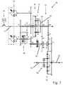
- Fig. 3shows a schematic diagram of a third embodiment of the power split transmission 30 according to the invention, in which a first reversing stage 32 associated with the first branch 16 and a second reversing stage 40 associated with the second branch 22 are provided.
- the power split transmission 30functions in this embodiment as described in connection with the second embodiment. The same applies to the change from the first to the second forward driving range.
- the power split transmission 30 in this arrangementrequires the second reversing stage 40.
- the engine H2 at the transition from the first driving range to the second driving range (V / R) to the pumpit must in turn be swung in the opposite direction as soon as the clutch device K1 is opened.
- the coupling device K1can alternatively be arranged in the gear Z9.
- the coupling devices K2V / K2R of the second reversing stage 40can also be arranged in the gear pairing Z6 / Z6 '.
- the web output of the planetary gear assembly 18should be made connectable in opposite directions of rotation with the output 24.
- Fig. 4shows a schematic diagram of a fourth embodiment of the power split transmission 30 of the invention.
- the general operation of the fourth embodimentbasically corresponds to that of the third embodiment, the fourth embodiment has in particular an even more compact design of the reversing 32 and the other Reversiercut 40 and no separate differential gear 34 has.
- the gear pairings Z7 / Z6 / Z6 'and Z7' / Z7 "of the second reversing stage 40are arranged differently in comparison to the third exemplary embodiment
- the coupling device K1 shown in the third exemplary embodimentwas placed in the area of the output shaft 24 (VA / HA) and coupled via an additional gear Z9 'to the second hydrostatic unit H2, resulting in a different configuration of the second reversing stage 40.
- the first reversing stage 32differs in terms of the jaw clutches KR and KV in the construction from that in connection with FIG
- the bridge shaft 20is connected to the toothed wheel Z20, which in turn meshes with the toothed wheels Z21 and Z21 ', which can be coupled with the toothed wheels Z22 or Z22' via the dog clutches KR or KV and act via the gear Z23 on the coupling device K1, the other ends on the Gear pairing Z16 / Z9 / 'Z9 is in operative connection with the second reversing stage 40.
Landscapes
- Engineering & Computer Science (AREA)
- General Engineering & Computer Science (AREA)
- Mechanical Engineering (AREA)
- Structure Of Transmissions (AREA)
- Arrangement Of Transmissions (AREA)
Description
Translated fromGermanDie Erfindung betrifft ein Leistungsverzweigungsgetriebe für ein Kraftfahrzeug, insbesondere für eine selbstfahrende Arbeitsmaschine.The invention relates to a power split transmission for a motor vehicle, in particular for a self-propelled work machine.
Leistungsverzweigungsgetriebe dienen zur Leistungsübertragung über einen rein mechanischen und einen hydrostatischen bzw. elektrischen Zweig. Damit eignen sie sich insbesondere für Kraftfahrzeuge wie selbstfahrende Arbeitsmaschinen, Radlader oder dergleichen, die einerseits unter hoher Last anfahren können müssen, andererseits aber auch eine ausreichende Mindestgeschwindigkeit zur Fortbewegung auf öffentlichen Straßen aufweisen sollen. Ein gattungsgemäßes Leistungsverzweigungsgetriebe umfasst dazu eine Antriebswelle, welche zum Einspeisen von Drehmoment mit einer Brennkraftmaschine verbunden ist. Weiterhin umfasst das Leistungsverzweigungsgetriebe einen mechanischen ersten Zweig, der eine Planetengetriebeanordnung mit zwei Sonnenrädern unterschiedlichen Durchmessers, einem Hohlrad und einer Stegwelle umfasst, auf der Doppelplanetenräder angeordnet sind, die mit den Sonnenrädern und mit dem Hohlrad kämmen. Zumindest eines der Sonnenräder ist mit der Antriebswelle gekoppelt. Weiterhin umfasst ein solches Leistungsverzweigungsgetriebe einen stufenlos verstellbaren zweiten Zweig, der zumindest teilweise über die Planetengetriebeanordnung mit dem ersten Zweig verbindbar ist und zwei, drei oder mehr verstellbare hydraulische und/oder elektrische rotatorische Energiewandler umfasst, die miteinander energetisch koppelbar und jeweils in beide Richtungen entweder als Motor oder im Fall eines Hydromotors als Pumpe bzw. im Fall eines Elektromotors als Generator betreibbar sind. Schließlich umfasst ein derartiges Leistungsverzweigungsgetriebe eine Abtriebswelle, auf die der erste Zweig und der zweite Zweig gekoppelt werden. Üblicherweise stellen solche Leistungsverzweigungsgetriebe, wie sie beispielsweise in der
Nachteilig an dem bekannten Leistungsverzweigungsgetriebe ist sein Verhalten beim Rückwärtsfahren. Ausgangssituation ist der Stillstand des Kraftfahrzeugs. Zum Rückwärtsfahren in einem ersten Rückwärtsfahrbereich wird nun eine der Pumpen in umgekehrter Richtung als beim Vorwärtsfahren ausgeschwenkt. Hierdurch dreht der andere Hydrostat ebenfalls rückwärts und überlagert seine nun umgekehrte Drehbewegung am Abtrieb der Planetengetriebeanordnung. Das Fahrzeug fährt nun zwar rückwärts, die Planetengetriebeanordnung wird jedoch nach wie vor von der Brennkraftmaschine in "Vorwärts-Richtung" angetrieben. Ein Teil der Leistung fließt dadurch nicht dem Abtrieb zu, sondern wird als Blindleistung in der verspannten Planetengetriebeanordnung gehalten. Je schneller das Kraftfahrzeug rückwärts fährt, desto größer wird dieser Blindleistungsanteil, so dass eine Rückwärtsfahrt im einem mit dem zweiten Vorwärtsfahrbereich korrespondierenden Rückwärtsfahrbereich üblicherweise nicht möglich ist. Dieser Blindleistungsanteil übersteigt bei schneller Rückwärtsfahrt sogar die Eintriebsleistung und reduziert somit die Lebensdauer der Energiewandler sowie der betroffenen Zahnräder und Lagerstellen. Zudem erreicht ein mit einem derartigen Leistungsverzweigungsgetriebe ausgerüstetes Kraftfahrzeug rückwärts maximal ca. 1/3 der Vorwärts-Höchstgeschwindigkeit, weil nur in einem mit dem ersten Vorwärtsfahrbereich korrespondierenden ersten Rückwärtsfahrbereich, aber nicht in einem mit einem zweiten Vorwärtsfahrbereich korrespondierenden zweiten Rückwärtsfahrbereich gefahren werden kann. Die zunehmenden Leistungsverluste beim Rückwärtsfahren resultieren zudem in einer zunehmend nachlassenden Zugkraft, was zu Problemen bei rückwärts fahrenden Kraftfahrzeugen führen kann. Beispiele sind das Einfahren in eine Silage bei Traktoren sowie eine nicht ausreichende Zugkraft bei rückwärts fahrenden Bau- und Forstmaschinen. Bei Anwendungen mit häufiger Rückwärtsfahrt macht sich der Blindleistungsanteil zudem durch erhöhten Kraftstoffverbrauch negativ bemerkbar. Dies wird beispielsweise bei Traktoren akzeptiert, bei fahrbaren Arbeitsmaschinen wie beispielsweise Radladern und Forstmaschinen ist eine solche Einschränkung jedoch oftmals nicht hinnehmbar.A disadvantage of the known power split transmission is its behavior when reversing. Initial situation is the stoppage of the motor vehicle. To reverse in a first reverse range now one of the pumps is swung in the reverse direction than when driving forward. As a result, the other hydrostat also rotates backwards and superimposes its now reversed rotary motion on the output of the planetary gear arrangement. Although the vehicle now moves backwards, the planetary gear arrangement is still driven by the internal combustion engine in the "forward direction". Part of the power does not flow to the output, but is held as reactive power in the braced planetary gear arrangement. The faster the motor vehicle travels backwards, the greater is this reactive power component, so that a reverse drive in a reverse driving range corresponding to the second forward driving range is usually not possible. This reactive power component even exceeds the input power during fast reverse drive and thus reduces the service life of the energy converters and the affected gears and bearings. In addition, a motor vehicle equipped with such a power split transmission reaches a maximum of about 1/3 of the forward maximum speed, because only in a corresponding to the first forward driving range first reverse range, but not in a corresponding with a second forward range second reverse range can be driven. The increasing power losses when reversing also result in an increasingly diminishing traction, which can lead to problems in reversing vehicles. Examples are the entry into a silage with tractors as well as insufficient traction with reversing construction and forestry machines. In applications with frequent reversing, the reactive power share also has negative effects due to increased fuel consumption. This is for example accepted in tractors, but in mobile machines such as wheel loaders and forestry machines, such a restriction is often unacceptable.
Die
Die Aufgabe wird erfindungsgemäß durch ein Leistungsverzweigungsgetriebe mit den Merkmalen des Patentanspruchs 1 gelöst. Vorteilhafte Ausgestaltungen mit zweckmäßigen Weiterbildungen des Leistungsverzweigungsgetriebes sind in den Unteransprüchen angegeben.
Ein erfindungsgemäßes Leistungsverzweigungsgetriebe, welches ohne Blindleistung rückwärts bewegt werden kann, umfasst zwischen der Antriebswelle und der Abtriebswelle zumindest eine erste Reversierstufe zum Wechseln zwischen zumindest einem ersten Vorwärtsfahrbereich und zumindest einem ersten Rückwärtsfahrbereich, wobei die Reversierstufe die Drehrichtungen der Sonnenräder, des Hohlrads und der Stegwelle beim Wechseln zwischen dem ersten Vorwärtsfahrbereich und dem ersten Rückwärtsfahrbereich alle umkehrt. Mit anderen Worten ist eine mechanische Reversierstufe vorgesehen, welche beim Wechseln zwischen Vorwärtsfahrbereich und Rückwärtsfahrbereich die relativen Drehrichtungen der Sonnenräder, des Hohlrads und der Stegwelle zueinander gleichsinnig hält, so dass nicht einzelne Komponenten der Planetengetriebeanordnung reversiert werden, während andere Komponenten nicht reversiert werden. Hierdurch wird zuverlässig ausgeschlossen, dass es beim Wechsel zwischen Vorwärts- und Rückwärtsfahrt in der Planetengetriebeanordnung zu unerwünschten Drehrichtungsüberlagerungen kommt, so dass das erfindungsgemäße Leistungsverzweigungsgetriebe ohne Blindleistungsverluste wahlweise zumindest in einem ersten Vorwärtsfahrbereich sowie in einem ersten Rückwärtsfahrbereich bewegt werden kann. Dabei ist es grundsätzlich ausreichend, wenn das erfindungsgemäße Leistungsverzweigungsgetriebe mit nur einer Brennkraftmaschine und nur zwei Energiewandlern eines Kraftfahrzeugs verbindbar ist, die unabhängig voneinander als Hydromotor oder als Elektromotor ausgebildet sein können und dementsprechend als Motor oder Pumpe bzw. Generator fungieren können. Weiterhin kann es vorgesehen sein, dass der erste Energiewandler mit dem Hohlrad der Planetengetriebeanordnung koppelbar ist und/oder dass der zweite Energiewandler mit dem zweiten Sonnenrad der Planetengetriebeanordnung koppelbar ist. Das erfindungsgemäße Leistungsverzweigungsgetriebe eignet sich insbesondere für Kraftfahrzeuge wie selbstfahrende Arbeitsmaschinen.The object is achieved by a power split transmission with the features of claim 1. Advantageous embodiments with expedient developments of the power split transmission are specified in the subclaims.
An inventive power split transmission, which can be moved backward without reactive power comprises between the drive shaft and the output shaft at least a first reversing stage for changing between at least a first forward range and at least a first reverse range, the reversing the directions of rotation of the sun gears, the ring gear and the web shaft Switching between the first forward range and the first reverse range all reverses. In other words, a mechanical reversing stage is provided, which keeps the relative directions of rotation of the sun gears, the ring gear and the web shaft in the same direction when changing between forward range and reverse range, so that not individual components of the planetary gear assembly are reversed, while other components are not reversed. As a result, it is reliably ruled out that undesired rotational superimpositions occur when changing between forward and reverse travel in the planetary gear arrangement, so that the power branching transmission according to the invention can be selectively moved at least in a first forward driving range and in a first reverse driving range without reactive power losses. It is basically sufficient if the power split transmission according to the invention with only one internal combustion engine and only two energy converters of a motor vehicle is connected, which can be independently designed as a hydraulic motor or as an electric motor and accordingly can act as a motor or pump or generator. Furthermore, it can be provided that the first energy converter can be coupled to the ring gear of the planetary gear arrangement and / or that the second energy converter can be coupled to the second sun gear of the planetary gear arrangement. The power split transmission according to the invention is particularly suitable for motor vehicles such as self-propelled machines.
In einer vorteilhaften Ausgestaltung der Erfindung ist die erste Reversierstufe am Abtrieb der Planetengetriebeanordnung angeordnet und insbesondere mit der Stegwelle der Planetengetriebeanordnung gekoppelt. Dies hat den Vorteil, dass das Leistungsverzweigungsgetriebe rückwärts genauso wie vorwärts funktioniert, da lediglich die Drehrichtung des gesamten Leistungsverzweigungsgetriebes am Abtrieb durch die erste Reversierstufe umgekehrt wird, so dass keinerlei Drehrichtungsumkehr bei den einzelnen Komponenten der Planetengetriebeanordnung stattfindet. Damit kann die erste Reversierstufe auch bei bereits bestehenden Leistungsverzweigungsgetrieben auf einfache Weise als optionale Zusatzfunktion ergänzt werden.In an advantageous embodiment of the invention, the first reversing stage is arranged at the output of the planetary gear arrangement and coupled in particular with the web shaft of the planetary gear arrangement. This has the advantage that the power split transmission works backwards as well as forward, since only the direction of rotation of the entire power split transmission is reversed at the output by the first reversing stage, so that no reversal occurs in the individual components of the planetary gear arrangement. This means that the first reversing stage can be easily supplemented as an optional additional function even with existing power split transmissions.
In einer weiteren vorteilhaften Ausgestaltung der Erfindung ist vorgesehen, dass zwischen einer Abtriebsseite der Planetengetriebeanordnung und der Abtriebswelle wenigstens ein erstes Kupplungselement und ein zweites Kupplungselement vorgesehen sind, wobei im ersten Vorwärtsfahrbereich Drehmoment über das erste Kupplungselement und im ersten Rückwärtsfahrbereich Drehmoment über das zweite Kupplungselement zu übertragen ist. Hierdurch kann das vom Motor bzw. den Energiewandlern gelieferte Drehmoment durch Schalten der Kupplungselemente fahrtrichtungsabhängig blindleistungsfrei entweder über das erste Kupplungselement oder über das zweite Kupplungselement an die Abtriebwelle geleitet werden. Die Kupplungselemente können unabhängig voneinander beispielsweise als Klauenkupplung, Lamellenkupplung oder dergleichen ausgebildet sein.In a further advantageous embodiment of the invention, it is provided that between a driven side of the planetary gear and the output shaft at least a first coupling element and a second coupling element are provided to transmit torque in the first forward driving range torque on the first coupling element and in the first reverse range torque on the second coupling element is. As a result, the torque delivered by the engine or the energy converters can be guided by switching the coupling elements in a direction-dependent manner, either free of power or via the first coupling element or via the second coupling element to the output shaft. The coupling elements may be independently formed, for example, as a dog clutch, multi-plate clutch or the like.
Weitere Vorteile ergeben sich, indem die erste Reversierstufe eine erste Zahnradpaarung mit einer geraden Anzahl gepaarter Zahnräder und eine zweite Zahnradpaarung mit einer ungeraden Anzahl gepaarter Zahnräder umfasst und ausgebildet ist, Drehmoment beim Wechseln zwischen Vorwärtsfahrbereich und Rückwärtsfahrbereich entweder über die erste oder über die zweite Zahnradpaarung von der Planetengetriebeanordnung an die Abtriebswelle zu übertragen. Dies stellt eine konstruktiv besonders einfache, kompakte und kostengünstige Möglichkeit zur Realisierung eines blindleistungsfreien Wechsels zwischen Vorwärts- und Rückwärtsfahrtbereich dar.Further advantages result from the fact that the first reversing stage comprises a first gear pair with an even number of paired gears and a second gear pair with an odd number of paired gears and is designed to produce torque when changing between forward driving range and reverse driving range either via the first or the second gear pair of FIG to transmit the planetary gear assembly to the output shaft. This represents a structurally particularly simple, compact and cost-effective way to realize a blind power-free change between forward and reverse travel range.
In einer weiteren vorteilhaften Ausgestaltung der Erfindung ist die erste Reversierstufe als vormontierbare Modulbaugruppe ausgebildet. Hierdurch kann die erste Reversierstufe als Teilkomponente des Leistungsverzweigungsgetriebes vorgefertigt und beispielsweise als Zusatzoption oder Nachrüstlösung für das Leistungsverzweigungsgetriebe bereitgestellt werden, das somit konstruktiv zumindest weitgehend unverändert bleiben kann. Dies hat den Vorteil, dass unterschiedlich ausgebildete Leistungsverzweigungsgetriebe schnell und einfach mit einer jeweils optimal angepassten Reversierstufe versehen werden können. Die erste Reversierstufe kann dabei in einem zugeordneten Gehäuse bzw. Teilgehäuse aufgenommen sein. Ebenso genügt in Schadensfällen entweder der Austausch der Modulbaugruppe oder des restlichen Leistungsverzweigungsgetriebes, was beispielsweise die Reparatur von selbstfahrenden Arbeitsmaschinen entsprechend vereinfacht.In a further advantageous embodiment of the invention, the first reversing stage is designed as a preassemblable module assembly. As a result, the first reversing stage can be prefabricated as a subcomponent of the power split transmission and provided, for example, as an additional option or retrofit solution for the power split transmission, which thus can remain structurally at least largely unchanged. This has the advantage that differently designed power split transmission can be quickly and easily provided with a respectively optimally adapted Reversierstufe. The first reversing stage can be accommodated in an associated housing or partial housing. Equally sufficient in cases of damage either the replacement of the module assembly or the remaining power split transmission, which simplifies, for example, the repair of self-propelled machines accordingly.
Weiterhin kann es grundsätzlich vorgesehen sein, dass die erste Reversierstufe das erste und das zweite Kupplungselement umfasst, mittels welchen beim Wechseln zwischen Vorwärtsfahrbereich und Rückwärtsfahrbereich entweder die erste Zahnradpaarung oder die zweite Zahnradpaarung zum Übertragen von Drehmoment mit der Planetengetriebeanordnung koppelbar ist. Da der Wechsel zwischen Vorwärts- und Rückwärtsfahrbereich im Stillstand des Kraftfahrzeugs geschieht, können die Kupplungselemente als kostengünstige und kompakte Klauenkupplungen ausgeführt sein. Alternativ können aber auch in diesem Fall andere Kupplungstypen wie z.B. Lamellenkupplungen vorgesehen sein.Furthermore, it can be provided in principle that the first reversing stage comprises the first and the second coupling element, by means of which when switching between forward range and reverse range either the first gear pair or the second gear pair for transmitting torque to the planetary gear assembly can be coupled. Since the change between forward and reverse driving range occurs at standstill of the motor vehicle, the coupling elements can be designed as cost-effective and compact jaw clutches. Alternatively, however, other types of coupling, such as e.g. Lamella clutches may be provided.
Weitere Vorteile ergeben sich, indem zwischen der ersten Reversierstufe und der wenigstens einen Abtriebwelle ein vorzugsweise mittels einer Differentialsperre sperrbares Differentialgetriebe vorgesehen ist, mittels welchem ein Drehmoment zwischen einer ersten Abtriebswelle und einer zweiten Abtriebswelle aufteilbar ist. Hierdurch ist eine funktionelle Erweiterung des Leistungsverzweigungsgetriebes mit einem als Achs-Verteilergetriebe fungierenden Differentialgetriebe ermöglicht, mittels welchem das Drehmoment beispielsweise auf eine Vorder- und eine Hinterachse eines zugeordneten Fahrzeugs verteilt werden kann. Vorzugsweise umfasst das Differentialgetriebe eine Differentialsperre, um durch starre Kopplung von Vorder- und Hinterachse zu verhindern, dass das Kraftfahrzeug aufgrund von Schlupf an einem der Räder verlangsamt wird oder gar zum Stillstand kommt.
In einer weiteren vorteilhaften Ausgestaltung der Erfindung ist vorgesehen, dass der erste Energiewandler und der zweite Energiewandler beim Wechseln zwischen dem ersten Vorwärtsfahrbereich und einem zweiten Vorwärtsfahrbereich ihre Funktion tauschen und/oder dass der erste Energiewandler und der zweite Energiewandler beim Wechseln zwischen dem ersten Vorwärtsfahrbereich und dem ersten Rückwärtsfahrbereich ihre Funktion beibehalten und/oder dass der erste Energiewandler und der zweite Energiewandler im ersten Vorwärtsfahrbereich und im ersten Rückwärtsfahrbereich jeweils gleichartig betrieben werden. Hierdurch ist eine besonders einfache Steuerung des Leistungsverzweigungsgetriebes ermöglicht, da im Hinblick auf die Energiewandler nicht zwischen Vorwärts- und Rückwärtsfahrt unterschieden werden muss. Die Steuerung kann dabei grundsätzlich manuell oder vorzugsweise automatisiert erfolgen. Erfindungsgemäß ist die erste Reversierstufe ausgebildet, eine Drehrichtung des Abtriebs der Planetengetriebeanordnung relativ zu einer Drehrichtung des zweiten Energiewandlers umzukehren. Dies stellt eine konstruktiv einfache Möglichkeit zur Vermeidung von Blindleistungsverlusten dar, da mittels der ersten Reversierstufe die Drehrichtung des Abtriebs des Planetentriebs zusammen mit der Drehrichtung des Energiewandlers umgekehrt wird.
In einer weiteren vorteilhaften Ausgestaltung der Erfindung ist vorgesehen, dass der zweite Energiewandler vorzugsweise mittels einer Kupplungseinrichtung mit einer Abtriebswelle koppelbar und von der Abtriebswelle entkoppelbar ist. Mit anderen Worten ist anstelle einer direkten Kopplung des zweiten Energiewandlers mit der Stegwelle der Planetengetriebeanordnung eine Kopplung des zweiten Energiewandlers mit der Abtriebswelle vorgesehen. Hierdurch kann der mechanische Zweig reversiert werden, bevor er über den zweiten Hydrostaten wieder mit dem hydrostatischen Leistungszweig gekoppelt wird. Dies bietet den Vorteil, dass nicht die Summe der Drehmomente aller Antriebsmotoren an einer Stelle im Leistungsverzweigungsgetriebe reversiert werden muss, sondern dass der mechanische und der hydrostatische bzw. elektrische Zweig unabhängig voneinander reversiert und erst nach der Reversierung wieder zusammengeführt werden können. Hierdurch kann das Leistungsverzweigungsgetriebe entsprechend kompakter ausgebildet werden. Grundsätzlich kann dabei wenigstens eine Kupplungseinrichtung vorgesehen sein, mittels welcher der zweite Energiewandler mit der Abtriebswelle koppelbar oder von der Abtriebswelle entkoppelbar ist. Hierdurch ist eine einfache Möglichkeit zur wahlweisen Einkopplung des Drehmoments des zweiten Energiewandlers gegeben, beispielsweise beim Wechsel zwischen unterschiedlichen Fahrstufen.Further advantages result from the fact that between the first reversing stage and the at least one output shaft, a differential gear which is preferably lockable by means of a differential lock is provided, by means of which a torque can be split between a first output shaft and a second output shaft. As a result, a functional extension of the power split transmission is possible with a functioning as an axle transfer case differential gear, by means of which the torque can be distributed for example to a front and a rear axle of an associated vehicle. Preferably, the differential gear includes a differential lock to rigidly coupled by front and Rear axle to prevent the motor vehicle is slowed down due to slippage on one of the wheels or even come to a standstill.
In a further advantageous embodiment of the invention, it is provided that the first energy converter and the second energy converter when changing between the first forward drive range and a second forward range change their function and / or that the first energy converter and the second energy converter when changing between the first forward range and the the first reverse drive range and / or that the first energy converter and the second energy converter in the first forward drive range and the first reverse drive range are operated in the same manner. As a result, a particularly simple control of the power split transmission is made possible, since with regard to the energy converter does not have to be distinguished between forward and reverse. The control can basically be done manually or preferably automated. According to the invention, the first reversing stage is designed to reverse a direction of rotation of the output of the planetary gear arrangement relative to a direction of rotation of the second energy converter. This is a structurally simple way to avoid reactive power losses, since by means of the first reversing stage, the direction of rotation of the output of the planetary drive is reversed together with the direction of rotation of the energy converter.
In a further advantageous embodiment of the invention it is provided that the second energy converter is preferably coupled by means of a coupling device with an output shaft and decoupled from the output shaft. In other words, instead of a direct coupling of the second energy converter with the ridge wave of the planetary gear arrangement, a coupling of the second energy converter to the output shaft is provided. As a result, the mechanical branch can be reversed before being coupled again to the hydrostatic power branch via the second hydrostat. This offers the advantage that the sum of the torques of all drive motors does not have to be reversed at one point in the power split transmission, but that the mechanical and the hydrostatic or electrical branch reversed independently and can be brought together again only after reversing. As a result, the power split transmission can be made correspondingly compact. In principle, at least one coupling device can be provided, by means of which the second energy converter can be coupled to the output shaft or decoupled from the output shaft. This provides a simple possibility for the optional coupling of the torque of the second energy converter, for example, when changing between different speed levels.
In einer weiteren vorteilhaften Ausgestaltung der Erfindung ist eine zweite Reversierstufe zum Wechseln zwischen dem ersten Rückwärtsfahrbereich und einem zweiten Rückwärtsfahrbereich vorgesehen. Hierdurch kann ein zweiter Rückwärtsfahrbereich bereitgestellt werden, wodurch das Fahrzeug mit gleicher Geschwindigkeit und ohne zusätzlich auftretende Blindleistung wahlweise vorwärts oder rückwärts bewegt werden kann.In a further advantageous embodiment of the invention, a second Reversierstufe for changing between the first reverse range and a second reverse range is provided. In this way, a second reverse range can be provided, whereby the vehicle can be moved forward or backward at the same speed and without additionally occurring reactive power.
Weitere Vorteile ergeben sich, indem die zweite Reversierstufe ausgebildet ist, eine Drehrichtung des zweiten Sonnenrads relativ zur Drehrichtung des zweiten Hydrostaten umzukehren. Dies erlaubt eine einfache Anpassung der Drehrichtungen des ersten und des zweiten Hydrostaten beim Durchfahren des zweiten Rückwärtsfahrbereichs.Further advantages result from the second reversing stage being designed to reverse a direction of rotation of the second sun gear relative to the direction of rotation of the second hydrostatic drive. This allows a simple adjustment of the directions of rotation of the first and the second Hydrostaten when driving through the second reverse range.
Eine besonders bauraumsparende Anordnung wird in weiterer Ausgestaltung der Erfindung dadurch erreicht, dass die zweite Reversierstufe zwischen dem zweiten Energiewandler und dem Planetengetriebeanordnung angeordnet ist.A particularly space-saving arrangement is achieved in a further embodiment of the invention in that the second reversing stage is arranged between the second energy converter and the planetary gear arrangement.
Weiterhin hat es sich als vorteilhaft gezeigt, wenn die erste Reversierstufe dem ersten Zweig und die zweite Reversierstufe dem zweiten Zweig zugeordnet ist. Dies erlaubt eine besonders flexible und voneinander getrennte Reversierung des mechanischen und des hydraulischen bzw. elektrischen Zweigs des Leistungsverzweigungsgetriebes.Furthermore, it has proven to be advantageous if the first reversing stage is assigned to the first branch and the second reversing stage to the second branch. This allows a particularly flexible and separate reversing of the mechanical and the hydraulic or electrical branch of the power split transmission.
Weitere Vorteile ergeben sich, wenn der erste Energiewandler und der zweite Energiewandler beim Wechseln zwischen dem ersten Rückwärtsfahrbereich und dem zweiten Rückwärtsfahrbereich ihre Funktion tauschen und/oder wenn der erste Energiewandler im zweiten Rückwärtsfahrbereich umgekehrt ausgeschwenkt wird als im zweiten Vorwärtsfahrbereich. Dies stellt eine konstruktiv einfache Möglichkeit zum Wechseln zwischen erstem und zweitem Rückwärtsfahrbereich dar.
Eine weitere vorteilhafte Möglichkeit zur bauraumsparenden Ausgestaltung des Leistungsverzweigungsgetriebes wird dadurch erreicht, dass wenigstens zwei Kupplungselemente in einer gemeinsamen Baugruppe zusammengefasst sind. Durch diese modulare Bauweise werden zudem die Montage und Demontage der wenigstens zwei Kupplungen erleichtert. Weiterhin können unterschiedliche Kupplungskombinationen vorgefertigt bereitgestellt und in Abhängigkeit der Ausgestaltung und des jeweiligen Einsatzzwecks des Leistungsverzweigungsgetriebes verbaut werden. Weitere Merkmale der Erfindung ergeben sich aus den Ansprüchen, den Ausführungsbeispielen sowie anhand der Zeichnungen. Die vorstehend in der Beschreibung genannten Merkmale und Merkmalskombinationen sowie die nachfolgend in den Ausführungsbeispielen genannten Merkmale und Merkmalskombinationen sind nicht nur in der jeweils angegebenen Kombination, sondern auch in anderen Kombinationen verwendbar, ohne den Rahmen der Erfindung zu verlassen. Dabei zeigt:
- Fig. 1
- eine Prinzipdarstellung eines ersten Ausführungsbeispiels eines nicht beanspruchten Leistungsverzweigungsgetriebes;
- Fig. 2
- eine Prinzipdarstellung eines zweiten Ausführungsbeispiels eines erfindungsgemäßen Leistungsverzweigungsgetriebes;
- Fig. 3
- eine Prinzipdarstellung eines dritten Ausführungsbeispiels des erfindungsgemäßen Leistungsverzweigungsgetriebes; und
- Fig. 4
- eine Prinzipdarstellung eines vierten Ausführungsbeispiels des erfindungsgemäßen Leistungsverzweigungsgetriebes.
A further advantageous possibility for space-saving design of the power split transmission is achieved in that at least two coupling elements are combined in a common assembly. This modular design also facilitates the assembly and disassembly of the at least two clutches. Furthermore, different coupling combinations can be prefabricated provided and installed depending on the design and the respective application purpose of the power split transmission. Further features of the invention will become apparent from the claims, the exemplary embodiments and with reference to the drawings. The features and combinations of features mentioned above in the description as well as the features and combinations of features mentioned below in the exemplary embodiments can be used not only in the respectively specified combination but also in other combinations, without departing from the scope of the invention. Showing:
- Fig. 1
- a schematic diagram of a first embodiment of an unclaimed power split transmission;
- Fig. 2
- a schematic diagram of a second embodiment of a power split transmission according to the invention;
- Fig. 3
- a schematic diagram of a third embodiment of the power split transmission according to the invention; and
- Fig. 4
- a schematic diagram of a fourth embodiment of the power split transmission according to the invention.
Ferner umfasst das Leistungsverzweigungsgetriebe 30 eine Abtriebswelle 24, auf die der erste Zweig 16 und der zweite Zweig 22 mittels der Zahnradstufe Z8/Z9 gekoppelt werden kann. Beim dem Leistungsverzweigungsgetriebe 30 ist das Abtriebsrad Z8 an der Stegwelle 20 der Planetengetriebeanordnung 18 mit dem Zahnrad Z10 einer ersten Reversierstufe 32 in Eingriff gebracht oder zumindest gekoppelt. Die erste Reversierstufe 32 ist ihrerseits als vormontierbare Modulbaugruppe ausgebildet und in einem separaten Gehäuse 33 aufgenommen, welches mit dem Gehäuse 15 verbunden ist.
Further, the
Für einen ersten Vorwärtsfahrbereich wird in der ersten Reversierstufe 32 eine erste Kupplungseinrichtung KV geschlossen und eine zweite Kupplungseinrichtung KR geöffnet. Damit dreht sich eine erste Abtriebswelle 24' beim Zahnrad Z15 gleichsinnig mit dem Zahnrad Z8 der Planetengetriebeanordnung 18. Die ungerade Zahnradpaarung Z10/Z12/Z11 dreht leer mit und überträgt keine Leistung.For a first forward driving range, a first clutch device KV is closed in the first reversing
Für einen ersten Rückwärtsfahrtbereich wird die Kupplungseinrichtung KV geöffnet, während die Kupplungseinrichtung KR geschlossen wird. Die Abtriebswelle 24' beim Zahnrad Z15 dreht nun gegensinnig mit dem Zahnrad Z8 der Planetengetriebeanordnung 18. Die gerade Zahnradpaarung Z13/Z15 dreht leer mit und überträgt keine Leistung.For a first reverse range, the clutch KV is opened while the clutch KR is closed. The output shaft 24 'of the gear Z15 now rotates in the opposite direction to the gear Z8 of the
Die Funktionen der Hydrostaten H1 und H2 sowie der Kupplungseinrichtungen K1 und K2 bleiben bei dieser Anordnung unbeeinflusst, so dass das Leistungsverzweigungsgetriebe 30 rückwärts genauso wie vorwärts blindleistungsfrei funktioniert, da die Drehrichtung des im Gehäuse 15 untergebrachten Getriebeteils am Abtrieb mittels der ersten Reversierstufe 32 vollständig umgekehrt wird. Mit anderen Worten werden die überlagerten Drehmomente des mechanischen Zweigs 16 und des hydrostatischen Zweigs 22 vor der Reversierstufe 32 zusammengeführt und anschließend gemeinsam reversiert. Damit stellt das gezeigte Leistungsverzweigungsgetriebe 30 zwei Vorwärtsgänge und zwei korrespondierende Rückwärtsgänge zur Verfügung, die blindleistungsfrei durchfahrbar sind.The functions of the hydrostats H1 and H2 as well as the coupling devices K1 and K2 remain unaffected in this arrangement, so that the
Da die Umschaltung Vorwärts/Rückwärts im Stillstand geschieht, können die Kupplungseinrichtungen KV/KR zudem vorteilhaft als Klauenkupplungen ausgeführt werden. Denkbar sind aber auch andere Formen von Kupplungen wie z. B. Lamellenkupplungen. Der Abtrieb über die Abtriebswelle 24' auf die Hinterachse HA' ist vor allem für Fahrzeuge vorteilhaft, die ein vergleichsweise kurzes Stichmaß zwischen Ein- und Abtrieb benötigen.Since the switching forward / backward happens at a standstill, the coupling devices KV / KR can also be advantageously carried out as jaw clutches. Conceivable but other forms of couplings such. B. multi-plate clutches. The output via the output shaft 24 'on the rear axle HA' is particularly advantageous for vehicles that require a relatively short gauge between input and output.
Alternativ oder zusätzlich kann auch eine Erweiterung des Leistungsverzweigungsgetriebes 30 mit einem als Achs-Verteilergetriebe ausgebildeten Differentialgetriebe 34 vorgesehen sein. Mit Hilfe des Differentialgetriebes 34 kann ausgehend vom Zahnrad Z14 das Drehmoment über ein vorzugsweise sperrbares Planetengetriebe 36 auf eine Vorderachse VA und eine Hinterachse HA verteilt werden. Eine solche Anordnung ist vor allem für Fahrzeuge vorteilhaft, die ein längeres Stichmaß vom Eintrieb zum Abtrieb benötigen, wie z. B. Radlader.Alternatively or additionally, an extension of the
In einem ersten Vorwärtsfahrbereich fungiert der Hydrostat H1 als Pumpe, während der Hydrostat H2 als Motor fungiert. Der Verbrennungsmotor 14 treibt die PLG 18 über das Sonnenrad Z1 an. Das Hohlrad Z3 stützt sich über die Zahnradpaarung Z4/Z5 an der Pumpe H1 ab. Der Steg 20 wirkt über die Reversierstufe 32 (Zahnradpaarungen Z20/Z21 und Z20'/Z21') als Abtrieb. Die Kupplungseinrichtung K1 wird geschlossen, während die Kupplungseinrichtung K2V geöffnet ist. Der Hydrostat H2 wird nun über die Zahnradpaarung Z9/Z16 mit dem Abtrieb der mechanischen Reversierstufe 32 verbunden. Die vorliegend eine Zahnradkette umfassende Zahnradpaarung Z1'/Z6/Z7 läuft leer mit und überträgt keine Leistung.In a first forward range, the hydrostat H1 acts as a pump, while the hydrostat H2 acts as a motor. The
Bei Vorwärtsfahrt funktionieren also das in
Die Anordnung der Reversierstufe 32 am Steg 20 der PLG 18 und die nachträgliche Einkopplung des Hydrostaten H2 sind aus mehreren Gründen vorteilhaft. Da die Kupplungen KV und KR nur den mechanischen Anteil des Drehmoments aus der PLG 18 tragen müssen, nicht jedoch zusätzlich das hohe Drehmoment des Hydrostaten H2, können sie bedeutend kleiner und leichter ausgelegt werden. Beim Umschalten der Kupplungseinrichtung KV und KR wird ferner der Abtrieb des Leistungsverzweigungsgetriebes 30 lediglich kurzzeitig von der PLG 18 getrennt. Das Fahrzeug setzt sich aber auch am Hang nicht in Bewegung, weil das Drehmoment am Abtrieb über den Hydrostaten H1 in gestreckter Lage abgestützt wird. Durch die Anordnung der Kupplungseinrichtung KV und KR zwischen PLG 18 und Energiewandler H2 ergibt sich schließlich eine "automatische" Verdrehung der Kupplungen KV/KR beim Schalten. Solange eine der Kupplungen KV/KR geschlossen ist, treibt die Brennkraftmaschine 14 den als Pumpe fungierenden Hydromotor H1 in gestreckter Lage an. Die Sonnenradwelle Z1 der Planetengetriebeanordnung 18 stützt sich am stehenden Fahrzeug ab. Wenn beim Schalten beide Kupplungen KV/KR öffnen, verlangsamt sich die Drehbewegung an der Pumpe H1, weil deren Schleppmoment das Hohlrad Z3 abbremst und die Brennkraftmaschine 14 beginnt, die nunmehr offene Reversierstufe 32 zu beschleunigen. Somit kann das Leistungsverzweigungsgetriebe 30 derart gesteuert werden, dass beim Umschalten zwischen Vorwärts- und Rückwärtsfahrt die KR-Kupplung bereits mit Druck beaufschlagt wird, bevor die KV-Kupplung öffnet. Die KR-Kupplung wird dann in vielen Fällen noch nicht schließen, weil sie Zahn auf Zahn steht. Wenn dann die KV-Kupplung öffnet, verdreht die Brennkraftmaschine 14 die Klauen der KR-Kupplung gegeneinander, so dass diese in die nächste freie Zahnlücke rutschen.The arrangement of the
Wenn die Höchstgeschwindigkeit des ersten Vorwärtsfahrbereichs bei korrespondierender Rückwärtsfahrt erreicht wird, befindet sich der als Pumpe fungierende Hydromotor H1 voll ausgeschwenkt in Richtung "rückwärts", während der Hydromotor H2 sich in gestreckter Lage befindet. Wie bereits erwähnt wurde, genügt es für viele Anwendungen, dass nur der erste Vorwärtsfahrbereich voll reversierbar ist und somit ohne Blindleistung betrieben werden kann, wie dies im zweiten Ausführungsbeispiel gezeigt wurde.If the maximum speed of the first forward driving range is achieved with a corresponding reverse drive, the hydraulic motor H1 acting as a pump is fully swung out in the "backwards" direction, while the hydraulic motor H2 is in an extended position. As already mentioned, it is sufficient for many applications that only the first forward driving range is fully reversible and thus can be operated without reactive power, as shown in the second embodiment.
Soll das Kraftfahrzeug jedoch vorwärts wie rückwärts dieselbe Geschwindigkeit erreichen können, benötigt das Leistungsverzweigungsgetriebe 30 in dieser Anordnung die zweite Reversierstufe 40. Damit der Motor H2 beim Übergang vom ersten Fahrbereich zum zweiten Fahrbereich (V/R) zur Pumpe werden kann, muss er seinerseits in entgegen gesetzter Richtung ausgeschwenkt werden, sobald die Kupplungseinrichtung K1 geöffnet wird.However, if the motor vehicle can achieve the same speed both forward and reverse, the
Dann passt aber seine Drehrichtung nicht mehr zu derjenigen des Hydrostaten H1 und muss also ebenfalls umgedreht werden. Dies wird durch die zweite Reversierstufe 40 mit der Zahnradpaarung Z6'/Z7"/Z7' erreicht. Das Leistungsverzweigungsgetriebe 30 ist somit auch im zweiten Fahrbereich vollständig und blindleistungsfrei reversierbar, indem die Pumpe H2, der Motor H1 und der Abtrieb über Z20/Z21 in umgekehrter Drehrichtung drehen. Die Kupplungen K2V, K2R sind als Teil der zweiten Reversierstufe 40 zwischen den Zahnradpaarungen Z6/Z7 und Z6'/Z7"/Z7' angeordnet und vorliegend als kompakte Baugruppe zusammengefasst. Im zweiten Vorwärtsgang wird die Kupplung K2V geschlossen, während die Kupplung K2R geöffnet wird, im zweiten Rückwärtsgang wird die Kupplung K2R geschlossen, während die andere Kupplung K2V geöffnet wird.But then his direction of rotation no longer matches that of the hydrostatic H1 and must therefore also be reversed. This is achieved by means of the second reversing
Es ist zu betonen, dass im Rahmen der Erfindung verschiedene konstruktive Varianten des Leistungsverzweigungsgetriebes 30 vorgesehen sein können. So kann beispielsweise die Kupplungseinrichtung K1 alternativ auch beim Zahnrad Z9 angeordnet werden. Alternativ oder zusätzlich können die Kupplungseinrichtungen K2V/K2R der zweiten Reversierstufe 40 auch bei der Zahnradpaarung Z6/Z6' angeordnet werden. In erster Linie sollte lediglich darauf geachtet werden, dass der Hydrostat H2 mit dem zweiten Sonnenrad Z1' in gegensätzlichen Drehrichtungen verbindbar gemacht werden kann und dass der Hydrostat H2 über die Kupplungseinrichtung K1 nach der Reversierung des mechanischen Zweigs 16 mit dem Abtrieb 24 verbunden werden kann. Ebenso sollte der Steg-Abtrieb der Planetengetriebeanordnung 18 in gegensätzlichen Drehrichtungen mit dem Abtrieb 24 verbindbar gemacht werden.It should be emphasized that various design variants of the
Claims (14)
- Power split gearbox (30) for a motor vehicle, in particular for a self-propelled work machine, including:- at least one drive shaft (12), which is connectible to an internal combustion engine (14) for inputting torque;- a first branch (16), which includes a planetary gear mechanism arrangement (18) with at least two sun gears (Z1, Z1'), an internal gear (Z3) and a spider shaft (20), on which dual planetary gears (Z2, Z2') are disposed, which mesh with the sun gears (Z1, Z1') and with the internal gear (Z3), wherein at least one of the sun gears (Z1) is coupled to the drive shaft (12);- an infinitely variable second branch (22), which can at least partially be connected to the first branch (16) via the planetary gear mechanism arrangement (18) and includes at least two adjustable hydraulic rotational energy converters (H1, H2) or at least two adjustable electrical rotational energy converters (H1, H2), which can be energetically coupled to each other and are each operable in both directions as a motor or a pump or generator, respectively; and- at least one output shaft (24), which can be coupled to the drive shaft (12) via the first branch (16) and the second branch (22);wherein at least one first reversing stage (32) for changing between at least one first forward driving range and at least one first reverse driving range is provided between the drive shaft (12) and the output shaft (24), wherein the reversing stage (32) reverses all of the rotational directions of the sun gears (Z1, Z1'), of the internal gear (Z3) and the spider shaft (20) upon changing between the first forward driving range and the first reverse driving range,
characterized in that
the first reversing stage (32) is configured to reverse a rotational direction of an output of the planetary gear mechanism arrangement (18) relative to a rotational direction of the second energy converter (H2). - Power split gearbox (30) according to claim 1,
characterized in that
the first reversing stage (32) is disposed at the output of the planetary gear mechanism arrangement (18) and in particular coupled to the spider shaft (20) of the planetary gear mechanism arrangement (18). - Power split gearbox (30) according to claim 1 or 2,
characterized in that
at least one first clutch element (KV) and one second clutch element (KR) are provided between an output side of the planetary gear mechanism arrangement (18) and the output shaft (24), wherein torque is to be transmitted via the first clutch element (KV) in the first forward driving range and torque is to be transmitted via the second clutch element (KR) in the first reverse driving range. - Power split gearbox (30) according to any one of claims 1 to 3,
characterized in that
the first reversing stage (32) includes a first gear pairing with an even number of paired gears (Z20, Z21) and a second gear pairing with an odd number of paired gears (Z20', Z22, Z21') and is formed to transmit torque from the planetary gear mechanism arrangement (18) to the output shaft (24) either via the first or via the second gear pairing upon changing between forward driving range and reverse driving range. - Power split gearbox (30) according to any one of claims 1 to 4,
characterized in that
the first reversing stage (32) is formed as a pre-mountable module assembly. - Power split gearbox (30) according to any one of claims 1 to 5,
characterized in that
a differential gear (34) preferably lockable by means of a differential lock (36) is provided between the first reversing stage (32) and the at least one output shaft (24), by means of which a torque can be divided between a first output shaft (24VA) and a second output shaft (24HA). - Power split gearbox (30) according to any one of claims 1 to 6,
characterized in that
the first energy converter (H1) and the second energy converter (H2) exchange their function upon change between the first forward driving range and a second forward driving range and/or that the first energy converter (H1) and the second energy converter (H2) maintain their function upon change between the first forward driving range and the first reverse driving range and/or that the first energy converter (H1) and the second energy converter (H2) are each similarly operated in the first forward drive range and in the first reverse driving range. - Power split gearbox (30) according to any one of claims 1 to 7,
characterized in that
the second energy converter (H2) can be coupled to an output shaft (38) and decoupled from the output shaft (38) preferably by means of a clutch device (K1). - Power split gearbox (30) according to any one of claims 1 to 8,
characterized in that
a second reversing stage (40) is provided for changing between the first reverse driving range and a second reverse driving range. - Power split gearbox (30) according to claim 9,
characterized in that
the second reversing stage (40) is formed to reverse a rotational direction of the second sun gear (Z1') relative to the rotational direction of the second energy converter (H2). - Power split gearbox (30) according to claim 9 or 10,
characterized in that
the second reversing stage (40) is disposed between the second energy converter (H2) and the planetary gear mechanism arrangement (18). - Power split gearbox (30) according to any one of claims 9 to 11,
characterized in that
the first reversing stage (32) is associated with the first branch (16) and the second reversing stage (40) is associated with the second branch (22). - Power split gearbox (30) according to any one of claims 9 to 12, if depending on claim 7,
characterized in that
the first energy converter (H1) and the second energy converter (H2) exchange their function upon change between the first reverse driving range and the second reverse driving range and/or that the first energy converter (H1) is reversely operated in the second reverse driving range to the second forward driving range. - Power split gearbox (30) according to any one of claims 1 to 13,
characterized in that
at least two clutch elements (K2V, K2R) are combined in a common assembly group.
Priority Applications (5)
| Application Number | Priority Date | Filing Date | Title |
|---|---|---|---|
| EP14200203.9AEP3037692B1 (en) | 2014-12-23 | 2014-12-23 | Power split drive for a motor vehicle |
| US15/538,711US10495204B2 (en) | 2014-12-23 | 2015-12-22 | Power split gearbox for a motor vehicle |
| RU2017126011ARU2676357C1 (en) | 2014-12-23 | 2015-12-22 | Transmission box with power distribution |
| PCT/EP2015/080985WO2016102572A1 (en) | 2014-12-23 | 2015-12-22 | Power split gearbox for a motor vehicle |
| CN201580070940.0ACN107110305B (en) | 2014-12-23 | 2015-12-22 | Power branch gearbox for motor vehicle |
Applications Claiming Priority (1)
| Application Number | Priority Date | Filing Date | Title |
|---|---|---|---|
| EP14200203.9AEP3037692B1 (en) | 2014-12-23 | 2014-12-23 | Power split drive for a motor vehicle |
Publications (2)
| Publication Number | Publication Date |
|---|---|
| EP3037692A1 EP3037692A1 (en) | 2016-06-29 |
| EP3037692B1true EP3037692B1 (en) | 2018-02-07 |
Family
ID=52232011
Family Applications (1)
| Application Number | Title | Priority Date | Filing Date |
|---|---|---|---|
| EP14200203.9AActiveEP3037692B1 (en) | 2014-12-23 | 2014-12-23 | Power split drive for a motor vehicle |
Country Status (5)
| Country | Link |
|---|---|
| US (1) | US10495204B2 (en) |
| EP (1) | EP3037692B1 (en) |
| CN (1) | CN107110305B (en) |
| RU (1) | RU2676357C1 (en) |
| WO (1) | WO2016102572A1 (en) |
Families Citing this family (10)
| Publication number | Priority date | Publication date | Assignee | Title |
|---|---|---|---|---|
| DE102016216315A1 (en)* | 2016-08-30 | 2018-03-01 | Volkswagen Aktiengesellschaft | Drive arrangement for a motor vehicle |
| CN107143636B (en)* | 2017-05-02 | 2019-04-19 | 北京理工大学 | Three-stage hydraulic-mechanical stepless transmission for loaders |
| AT520217B1 (en)* | 2017-07-21 | 2019-02-15 | Avl Commercial Driveline & Tractor Eng Gmbh | POWER BRANCHING TRANSMISSION |
| CN110805675B (en)* | 2019-10-08 | 2020-11-24 | 长沙桑铼特农业机械设备有限公司 | Multi-mode output integrated pump motor and application method thereof |
| CN111231650B (en)* | 2020-01-08 | 2022-11-15 | 同济大学 | Tractor power split hybrid power system and control method thereof |
| EP4151885B1 (en) | 2021-09-16 | 2025-10-08 | Dziuba Gears GmbH | Power split transmission, method for operating a power split transmission and motor vehicle with a power split transmission |
| DE202021004446U1 (en) | 2021-09-16 | 2024-08-29 | Dziuba Gears Gmbh | power split transmission and motor vehicle with a power split transmission |
| EP4249769A1 (en) | 2022-03-22 | 2023-09-27 | Fuss Spezialfahrzeugbau GmbH | Power split transmission for a motor vehicle with low reactive power and a large speed range |
| CN116624572B (en)* | 2023-04-27 | 2025-08-08 | 杭州前进齿轮箱集团股份有限公司 | Dual-clutch multi-speed transmission |
| DE102024124430B3 (en)* | 2024-08-27 | 2025-10-02 | Dziuba Gears Gmbh | Gear arrangement and motor vehicle with a gear arrangement |
Family Cites Families (15)
| Publication number | Priority date | Publication date | Assignee | Title |
|---|---|---|---|---|
| DE2904572C2 (en) | 1979-02-07 | 1984-04-05 | M.A.N. Maschinenfabrik Augsburg-Nürnberg AG, 8000 München | Hydrostatic-mechanical power split transmission |
| SU901091A2 (en)* | 1979-05-24 | 1982-01-30 | Предприятие П/Я А-1697 | Tractor hydraulic drive |
| DE3726080A1 (en)* | 1987-08-06 | 1989-02-16 | Man Nutzfahrzeuge Gmbh | HYDROMECHANICAL POWER BRANCHING GEARBOX FOR A VEHICLE |
| DE3817292A1 (en)* | 1988-05-20 | 1989-10-26 | Voith Gmbh J M | Torque dividing transmission |
| US6565471B2 (en)* | 2000-12-19 | 2003-05-20 | Case Corporation | Continuously variable hydro-mechanical transmission |
| DE102008040449A1 (en)* | 2008-07-16 | 2010-01-21 | Zf Friedrichshafen Ag | Hydrostatic mechanical power split transmission for use in e.g. tractor, has hydraulic unit and sun gear that are connected with main shaft over spur wheel sections and driving area clutches, respectively |
| US7892130B1 (en)* | 2007-12-04 | 2011-02-22 | Sauer-Dafoss Inc. | Transmission concept for dual yoke hydrostatic units |
| AT11545U1 (en)* | 2009-05-19 | 2010-12-15 | Heinz Dipl Ing Aitzetmueller | POWER BRANCHING TRANSMISSION |
| US8696509B2 (en)* | 2009-07-27 | 2014-04-15 | Dana Italia Spa | Power split transmission |
| US9097342B2 (en)* | 2010-01-05 | 2015-08-04 | Cnh Industrial America Llc | Method for estimating and controlling driveline torque in a continuously variable hydro-mechanical transmission |
| RU2013105451A (en)* | 2010-07-09 | 2014-08-20 | Мали Холдинг Аг | HYDRAULIC HYDROSTATIC-MECHANICAL TRANSMISSION WITH DIVISION OF POWER FLOW, METHOD OF OPERATION OF SUCH TRANSMISSION WITH DIVISION OF POWER FLOW, AND ALSO WHEEL LOADER WITH SUCH TRANSFER DIVISION |
| DE102010053012A1 (en)* | 2010-12-02 | 2012-06-06 | Claas Industrietechnik Gmbh | Hydromechanical transmission |
| BR112014008501A8 (en) | 2011-10-14 | 2017-06-20 | Abb Technology Ag | Multilevel converter and method for controlling the multilevel converter |
| US9447858B2 (en)* | 2011-11-14 | 2016-09-20 | Cnh Industrial America Llc | Hydro-mechanical continuously variable transmission for producing high torque output |
| US9975424B2 (en)* | 2015-05-15 | 2018-05-22 | Cnh Industrial America Llc | Dropbox assembly for transmission of work vehicle |
- 2014
- 2014-12-23EPEP14200203.9Apatent/EP3037692B1/enactiveActive
- 2015
- 2015-12-22USUS15/538,711patent/US10495204B2/enactiveActive
- 2015-12-22WOPCT/EP2015/080985patent/WO2016102572A1/enactiveApplication Filing
- 2015-12-22CNCN201580070940.0Apatent/CN107110305B/enactiveActive
- 2015-12-22RURU2017126011Apatent/RU2676357C1/enactive
Non-Patent Citations (1)
| Title |
|---|
| None* |
Also Published As
| Publication number | Publication date |
|---|---|
| CN107110305A (en) | 2017-08-29 |
| EP3037692A1 (en) | 2016-06-29 |
| US20180003280A1 (en) | 2018-01-04 |
| CN107110305B (en) | 2020-11-10 |
| WO2016102572A1 (en) | 2016-06-30 |
| US10495204B2 (en) | 2019-12-03 |
| RU2676357C1 (en) | 2018-12-28 |
Similar Documents
| Publication | Publication Date | Title |
|---|---|---|
| EP3037692B1 (en) | Power split drive for a motor vehicle | |
| EP1926620B1 (en) | Drive system for a vehicle, and agricultural vehicle | |
| EP3212447B1 (en) | Gearing device for a motor vehicle | |
| DE102014201254B4 (en) | Transmission arrangement and drive train for a hybrid vehicle and hybrid vehicle | |
| DE102015116537B4 (en) | Electric axle drive for a motor vehicle | |
| EP2215382B1 (en) | Torque-splitting transmission | |
| EP2253867A1 (en) | Power split drive | |
| EP3002146B1 (en) | Transmission assembly | |
| EP2258966A1 (en) | Summing drive | |
| EP4155578B1 (en) | Drive device for a motor vehicle drive train of an electric vehicle | |
| DE102014006232B4 (en) | Transmission device for a motor vehicle | |
| DE2239955C2 (en) | Gear change gears in group design for motor vehicles | |
| DE102017204336A1 (en) | Soil cultivation machine with manual transmission between drive motor and rotatable working device | |
| DE102020203391A1 (en) | Power-split continuously variable transmission | |
| DE102009013997A1 (en) | Crank-continuously variable transmission controlling method for motor vehicle, involves adjusting eccentricity of crank shaft of transmission in alternate adjusting directions, when drive power of engine of vehicle is not required | |
| WO2012146352A1 (en) | Drive device for a motor vehicle driven by a front, rear or all-wheel drive system | |
| EP3073149B1 (en) | Freewheel mechanism | |
| EP3034348B1 (en) | Distributor gear for dividing a torque to at least a first and a second axle shaft of a motor vehicle | |
| DE102020201690B3 (en) | Power-split continuously variable transmission | |
| WO2016173706A1 (en) | Working machine with power-branching drive | |
| EP1927788A1 (en) | Transmission device having hydraulic motors and planetary gear | |
| DE102006038068A1 (en) | Power split gearbox for e.g. wheeled loader, has summation gear section with output connected with input of another summation gear section, where latter summation gear section has another input connected with output of output branch | |
| DE102020201775B3 (en) | Power-split continuously variable transmission | |
| WO2020160864A1 (en) | Transmission device for a motor vehicle | |
| DE202015101190U1 (en) | Drive train for a motorized, mobile work machine |
Legal Events
| Date | Code | Title | Description |
|---|---|---|---|
| PUAI | Public reference made under article 153(3) epc to a published international application that has entered the european phase | Free format text:ORIGINAL CODE: 0009012 | |
| AK | Designated contracting states | Kind code of ref document:A1 Designated state(s):AL AT BE BG CH CY CZ DE DK EE ES FI FR GB GR HR HU IE IS IT LI LT LU LV MC MK MT NL NO PL PT RO RS SE SI SK SM TR | |
| AX | Request for extension of the european patent | Extension state:BA ME | |
| STAA | Information on the status of an ep patent application or granted ep patent | Free format text:STATUS: REQUEST FOR EXAMINATION WAS MADE | |
| 17P | Request for examination filed | Effective date:20161223 | |
| RBV | Designated contracting states (corrected) | Designated state(s):AL AT BE BG CH CY CZ DE DK EE ES FI FR GB GR HR HU IE IS IT LI LT LU LV MC MK MT NL NO PL PT RO RS SE SI SK SM TR | |
| RIC1 | Information provided on ipc code assigned before grant | Ipc:F16H 37/08 20060101ALN20170713BHEP Ipc:F16H 37/10 20060101ALN20170713BHEP Ipc:F16H 3/72 20060101ALI20170713BHEP Ipc:F16H 47/04 20060101AFI20170713BHEP | |
| RIC1 | Information provided on ipc code assigned before grant | Ipc:F16H 37/10 20060101ALN20170717BHEP Ipc:F16H 37/08 20060101ALN20170717BHEP Ipc:F16H 3/72 20060101ALI20170717BHEP Ipc:F16H 47/04 20060101AFI20170717BHEP | |
| GRAP | Despatch of communication of intention to grant a patent | Free format text:ORIGINAL CODE: EPIDOSNIGR1 | |
| STAA | Information on the status of an ep patent application or granted ep patent | Free format text:STATUS: GRANT OF PATENT IS INTENDED | |
| INTG | Intention to grant announced | Effective date:20170901 | |
| GRAS | Grant fee paid | Free format text:ORIGINAL CODE: EPIDOSNIGR3 | |
| GRAA | (expected) grant | Free format text:ORIGINAL CODE: 0009210 | |
| STAA | Information on the status of an ep patent application or granted ep patent | Free format text:STATUS: THE PATENT HAS BEEN GRANTED | |
| AK | Designated contracting states | Kind code of ref document:B1 Designated state(s):AL AT BE BG CH CY CZ DE DK EE ES FI FR GB GR HR HU IE IS IT LI LT LU LV MC MK MT NL NO PL PT RO RS SE SI SK SM TR | |
| REG | Reference to a national code | Ref country code:GB Ref legal event code:FG4D Free format text:NOT ENGLISH | |
| REG | Reference to a national code | Ref country code:AT Ref legal event code:REF Ref document number:968940 Country of ref document:AT Kind code of ref document:T Effective date:20180215 Ref country code:CH Ref legal event code:EP | |
| REG | Reference to a national code | Ref country code:IE Ref legal event code:FG4D Free format text:LANGUAGE OF EP DOCUMENT: GERMAN | |
| REG | Reference to a national code | Ref country code:DE Ref legal event code:R096 Ref document number:502014007200 Country of ref document:DE | |
| REG | Reference to a national code | Ref country code:SE Ref legal event code:TRGR | |
| REG | Reference to a national code | Ref country code:NL Ref legal event code:MP Effective date:20180207 | |
| PG25 | Lapsed in a contracting state [announced via postgrant information from national office to epo] | Ref country code:ES Free format text:LAPSE BECAUSE OF FAILURE TO SUBMIT A TRANSLATION OF THE DESCRIPTION OR TO PAY THE FEE WITHIN THE PRESCRIBED TIME-LIMIT Effective date:20180207 Ref country code:NL Free format text:LAPSE BECAUSE OF FAILURE TO SUBMIT A TRANSLATION OF THE DESCRIPTION OR TO PAY THE FEE WITHIN THE PRESCRIBED TIME-LIMIT Effective date:20180207 Ref country code:LT Free format text:LAPSE BECAUSE OF FAILURE TO SUBMIT A TRANSLATION OF THE DESCRIPTION OR TO PAY THE FEE WITHIN THE PRESCRIBED TIME-LIMIT Effective date:20180207 Ref country code:NO Free format text:LAPSE BECAUSE OF FAILURE TO SUBMIT A TRANSLATION OF THE DESCRIPTION OR TO PAY THE FEE WITHIN THE PRESCRIBED TIME-LIMIT Effective date:20180507 Ref country code:HR Free format text:LAPSE BECAUSE OF FAILURE TO SUBMIT A TRANSLATION OF THE DESCRIPTION OR TO PAY THE FEE WITHIN THE PRESCRIBED TIME-LIMIT Effective date:20180207 Ref country code:CY Free format text:LAPSE BECAUSE OF FAILURE TO SUBMIT A TRANSLATION OF THE DESCRIPTION OR TO PAY THE FEE WITHIN THE PRESCRIBED TIME-LIMIT Effective date:20180207 | |
| PG25 | Lapsed in a contracting state [announced via postgrant information from national office to epo] | Ref country code:PL Free format text:LAPSE BECAUSE OF FAILURE TO SUBMIT A TRANSLATION OF THE DESCRIPTION OR TO PAY THE FEE WITHIN THE PRESCRIBED TIME-LIMIT Effective date:20180207 Ref country code:IS Free format text:LAPSE BECAUSE OF FAILURE TO SUBMIT A TRANSLATION OF THE DESCRIPTION OR TO PAY THE FEE WITHIN THE PRESCRIBED TIME-LIMIT Effective date:20180607 Ref country code:LV Free format text:LAPSE BECAUSE OF FAILURE TO SUBMIT A TRANSLATION OF THE DESCRIPTION OR TO PAY THE FEE WITHIN THE PRESCRIBED TIME-LIMIT Effective date:20180207 Ref country code:GR Free format text:LAPSE BECAUSE OF FAILURE TO SUBMIT A TRANSLATION OF THE DESCRIPTION OR TO PAY THE FEE WITHIN THE PRESCRIBED TIME-LIMIT Effective date:20180508 Ref country code:BG Free format text:LAPSE BECAUSE OF FAILURE TO SUBMIT A TRANSLATION OF THE DESCRIPTION OR TO PAY THE FEE WITHIN THE PRESCRIBED TIME-LIMIT Effective date:20180507 Ref country code:RS Free format text:LAPSE BECAUSE OF FAILURE TO SUBMIT A TRANSLATION OF THE DESCRIPTION OR TO PAY THE FEE WITHIN THE PRESCRIBED TIME-LIMIT Effective date:20180207 | |
| PG25 | Lapsed in a contracting state [announced via postgrant information from national office to epo] | Ref country code:MT Free format text:LAPSE BECAUSE OF FAILURE TO SUBMIT A TRANSLATION OF THE DESCRIPTION OR TO PAY THE FEE WITHIN THE PRESCRIBED TIME-LIMIT Effective date:20180207 | |
| PG25 | Lapsed in a contracting state [announced via postgrant information from national office to epo] | Ref country code:AL Free format text:LAPSE BECAUSE OF FAILURE TO SUBMIT A TRANSLATION OF THE DESCRIPTION OR TO PAY THE FEE WITHIN THE PRESCRIBED TIME-LIMIT Effective date:20180207 Ref country code:EE Free format text:LAPSE BECAUSE OF FAILURE TO SUBMIT A TRANSLATION OF THE DESCRIPTION OR TO PAY THE FEE WITHIN THE PRESCRIBED TIME-LIMIT Effective date:20180207 Ref country code:RO Free format text:LAPSE BECAUSE OF FAILURE TO SUBMIT A TRANSLATION OF THE DESCRIPTION OR TO PAY THE FEE WITHIN THE PRESCRIBED TIME-LIMIT Effective date:20180207 | |
| REG | Reference to a national code | Ref country code:DE Ref legal event code:R097 Ref document number:502014007200 Country of ref document:DE | |
| PG25 | Lapsed in a contracting state [announced via postgrant information from national office to epo] | Ref country code:SM Free format text:LAPSE BECAUSE OF FAILURE TO SUBMIT A TRANSLATION OF THE DESCRIPTION OR TO PAY THE FEE WITHIN THE PRESCRIBED TIME-LIMIT Effective date:20180207 Ref country code:CZ Free format text:LAPSE BECAUSE OF FAILURE TO SUBMIT A TRANSLATION OF THE DESCRIPTION OR TO PAY THE FEE WITHIN THE PRESCRIBED TIME-LIMIT Effective date:20180207 Ref country code:SK Free format text:LAPSE BECAUSE OF FAILURE TO SUBMIT A TRANSLATION OF THE DESCRIPTION OR TO PAY THE FEE WITHIN THE PRESCRIBED TIME-LIMIT Effective date:20180207 Ref country code:DK Free format text:LAPSE BECAUSE OF FAILURE TO SUBMIT A TRANSLATION OF THE DESCRIPTION OR TO PAY THE FEE WITHIN THE PRESCRIBED TIME-LIMIT Effective date:20180207 | |
| PLBE | No opposition filed within time limit | Free format text:ORIGINAL CODE: 0009261 | |
| STAA | Information on the status of an ep patent application or granted ep patent | Free format text:STATUS: NO OPPOSITION FILED WITHIN TIME LIMIT | |
| 26N | No opposition filed | Effective date:20181108 | |
| PG25 | Lapsed in a contracting state [announced via postgrant information from national office to epo] | Ref country code:SI Free format text:LAPSE BECAUSE OF FAILURE TO SUBMIT A TRANSLATION OF THE DESCRIPTION OR TO PAY THE FEE WITHIN THE PRESCRIBED TIME-LIMIT Effective date:20180207 | |
| REG | Reference to a national code | Ref country code:CH Ref legal event code:PL | |
| PG25 | Lapsed in a contracting state [announced via postgrant information from national office to epo] | Ref country code:LU Free format text:LAPSE BECAUSE OF NON-PAYMENT OF DUE FEES Effective date:20181223 Ref country code:MC Free format text:LAPSE BECAUSE OF FAILURE TO SUBMIT A TRANSLATION OF THE DESCRIPTION OR TO PAY THE FEE WITHIN THE PRESCRIBED TIME-LIMIT Effective date:20180207 | |
| REG | Reference to a national code | Ref country code:IE Ref legal event code:MM4A | |
| REG | Reference to a national code | Ref country code:BE Ref legal event code:MM Effective date:20181231 | |
| PG25 | Lapsed in a contracting state [announced via postgrant information from national office to epo] | Ref country code:FR Free format text:LAPSE BECAUSE OF NON-PAYMENT OF DUE FEES Effective date:20181231 Ref country code:IE Free format text:LAPSE BECAUSE OF NON-PAYMENT OF DUE FEES Effective date:20181223 | |
| PG25 | Lapsed in a contracting state [announced via postgrant information from national office to epo] | Ref country code:BE Free format text:LAPSE BECAUSE OF NON-PAYMENT OF DUE FEES Effective date:20181231 | |
| PG25 | Lapsed in a contracting state [announced via postgrant information from national office to epo] | Ref country code:CH Free format text:LAPSE BECAUSE OF NON-PAYMENT OF DUE FEES Effective date:20181231 Ref country code:LI Free format text:LAPSE BECAUSE OF NON-PAYMENT OF DUE FEES Effective date:20181231 | |
| PG25 | Lapsed in a contracting state [announced via postgrant information from national office to epo] | Ref country code:TR Free format text:LAPSE BECAUSE OF FAILURE TO SUBMIT A TRANSLATION OF THE DESCRIPTION OR TO PAY THE FEE WITHIN THE PRESCRIBED TIME-LIMIT Effective date:20180207 | |
| PG25 | Lapsed in a contracting state [announced via postgrant information from national office to epo] | Ref country code:PT Free format text:LAPSE BECAUSE OF FAILURE TO SUBMIT A TRANSLATION OF THE DESCRIPTION OR TO PAY THE FEE WITHIN THE PRESCRIBED TIME-LIMIT Effective date:20180207 | |
| PG25 | Lapsed in a contracting state [announced via postgrant information from national office to epo] | Ref country code:HU Free format text:LAPSE BECAUSE OF FAILURE TO SUBMIT A TRANSLATION OF THE DESCRIPTION OR TO PAY THE FEE WITHIN THE PRESCRIBED TIME-LIMIT; INVALID AB INITIO Effective date:20141223 Ref country code:MK Free format text:LAPSE BECAUSE OF NON-PAYMENT OF DUE FEES Effective date:20180207 | |
| REG | Reference to a national code | Ref country code:AT Ref legal event code:MM01 Ref document number:968940 Country of ref document:AT Kind code of ref document:T Effective date:20191223 | |
| PG25 | Lapsed in a contracting state [announced via postgrant information from national office to epo] | Ref country code:AT Free format text:LAPSE BECAUSE OF NON-PAYMENT OF DUE FEES Effective date:20191223 | |
| P01 | Opt-out of the competence of the unified patent court (upc) registered | Effective date:20230525 | |
| PGFP | Annual fee paid to national office [announced via postgrant information from national office to epo] | Ref country code:FI Payment date:20241216 Year of fee payment:11 | |
| PGFP | Annual fee paid to national office [announced via postgrant information from national office to epo] | Ref country code:GB Payment date:20241218 Year of fee payment:11 | |
| PGFP | Annual fee paid to national office [announced via postgrant information from national office to epo] | Ref country code:IT Payment date:20241216 Year of fee payment:11 | |
| PGFP | Annual fee paid to national office [announced via postgrant information from national office to epo] | Ref country code:SE Payment date:20241217 Year of fee payment:11 | |
| PGFP | Annual fee paid to national office [announced via postgrant information from national office to epo] | Ref country code:DE Payment date:20241218 Year of fee payment:11 |