EP3037345B1 - A method of automatically controlling the descent phase of an aircraft using aircraft avionics executing a descent algorithm - Google Patents
A method of automatically controlling the descent phase of an aircraft using aircraft avionics executing a descent algorithmDownload PDFInfo
- Publication number
- EP3037345B1 EP3037345B1EP15197006.8AEP15197006AEP3037345B1EP 3037345 B1EP3037345 B1EP 3037345B1EP 15197006 AEP15197006 AEP 15197006AEP 3037345 B1EP3037345 B1EP 3037345B1
- Authority
- EP
- European Patent Office
- Prior art keywords
- aircraft
- airspeed
- speed
- descent
- input
- Prior art date
- Legal status (The legal status is an assumption and is not a legal conclusion. Google has not performed a legal analysis and makes no representation as to the accuracy of the status listed.)
- Active
Links
- 238000000034methodMethods0.000titleclaimsdescription22
- 230000004044responseEffects0.000claimsdescription2
- 239000000446fuelSubstances0.000description7
- 238000004891communicationMethods0.000description4
- 230000008901benefitEffects0.000description2
- 230000008859changeEffects0.000description2
- 238000013016dampingMethods0.000description2
- 238000010586diagramMethods0.000description2
- RZVHIXYEVGDQDX-UHFFFAOYSA-N9,10-anthraquinoneChemical compoundC1=CC=C2C(=O)C3=CC=CC=C3C(=O)C2=C1RZVHIXYEVGDQDX-UHFFFAOYSA-N0.000description1
- 230000001133accelerationEffects0.000description1
- 230000005540biological transmissionEffects0.000description1
- 230000008094contradictory effectEffects0.000description1
- 230000003247decreasing effectEffects0.000description1
- 230000000694effectsEffects0.000description1
- 230000007613environmental effectEffects0.000description1
- 230000006870functionEffects0.000description1
- 238000012423maintenanceMethods0.000description1
- 230000007704transitionEffects0.000description1
- 230000000007visual effectEffects0.000description1
Images


Classifications
- B—PERFORMING OPERATIONS; TRANSPORTING
- B64—AIRCRAFT; AVIATION; COSMONAUTICS
- B64C—AEROPLANES; HELICOPTERS
- B64C13/00—Control systems or transmitting systems for actuating flying-control surfaces, lift-increasing flaps, air brakes, or spoilers
- B64C13/02—Initiating means
- B64C13/16—Initiating means actuated automatically, e.g. responsive to gust detectors
- B64C13/18—Initiating means actuated automatically, e.g. responsive to gust detectors using automatic pilot
- G—PHYSICS
- G08—SIGNALLING
- G08G—TRAFFIC CONTROL SYSTEMS
- G08G5/00—Traffic control systems for aircraft
- G08G5/50—Navigation or guidance aids
- G08G5/54—Navigation or guidance aids for approach or landing
- B—PERFORMING OPERATIONS; TRANSPORTING
- B64—AIRCRAFT; AVIATION; COSMONAUTICS
- B64C—AEROPLANES; HELICOPTERS
- B64C13/00—Control systems or transmitting systems for actuating flying-control surfaces, lift-increasing flaps, air brakes, or spoilers
- B64C13/24—Transmitting means
- B64C13/38—Transmitting means with power amplification
- B64C13/50—Transmitting means with power amplification using electrical energy
- B64C13/503—Fly-by-Wire
- B—PERFORMING OPERATIONS; TRANSPORTING
- B64—AIRCRAFT; AVIATION; COSMONAUTICS
- B64C—AEROPLANES; HELICOPTERS
- B64C19/00—Aircraft control not otherwise provided for
- G—PHYSICS
- G05—CONTROLLING; REGULATING
- G05D—SYSTEMS FOR CONTROLLING OR REGULATING NON-ELECTRIC VARIABLES
- G05D1/00—Control of position, course, altitude or attitude of land, water, air or space vehicles, e.g. using automatic pilots
- G05D1/0088—Control of position, course, altitude or attitude of land, water, air or space vehicles, e.g. using automatic pilots characterized by the autonomous decision making process, e.g. artificial intelligence, predefined behaviours
- G—PHYSICS
- G05—CONTROLLING; REGULATING
- G05D—SYSTEMS FOR CONTROLLING OR REGULATING NON-ELECTRIC VARIABLES
- G05D1/00—Control of position, course, altitude or attitude of land, water, air or space vehicles, e.g. using automatic pilots
- G05D1/04—Control of altitude or depth
- G05D1/06—Rate of change of altitude or depth
- G05D1/0607—Rate of change of altitude or depth specially adapted for aircraft
- G05D1/0653—Rate of change of altitude or depth specially adapted for aircraft during a phase of take-off or landing
- G05D1/0676—Rate of change of altitude or depth specially adapted for aircraft during a phase of take-off or landing specially adapted for landing
Definitions
- the descent of an aircraft from a cruise phase to a landing phasemay be controlled for a variety of reasons, which may have contradictory goals.
- fuel conservationis the primary goal, it is common to perform an idle descent, where the engine is set at idle, i.e. minimum thrust, and controlling the path of descent using control surfaces.
- the aircraftmay encounter an over-speed condition, which is currently solved by the pilot deploying speed brakes, generating a great amount of noise, which many passengers do not like.
- speed brakesFor aircraft without speed brakes, other solutions, typically much less desirable, may be used.
- the pilotcan apply a pitch input into the aircraft, which change the trajectory and consumes additional fuel and defeating the purpose of the idle descent.
- Another alternative solutionis to utilize one or more of the aircraft avionics, like the Flight Management System and/or Flight Guidance System (FMS & FGS), and leave the engine throttle above idle, at approximately 10% and decrease the throttle when an over-speed condition occurs, which also consumes additional fuel and defeats the purpose of an idle descent.
- FMS & FGSFlight Management System and/or Flight Guidance System
- Airplane Flying HandbookFAA-H-8083-3A, of the U.S Department of Transportation Federal Aviation Administration, and dated 2004, describes on pages 8.10 to 8.11 thereof the use of a slip maneuver by pilots for decreasing the airspeed of an aircraft in an emergency and discloses features generally corresponding to the preamble of claim 1.
- EP 2151730 A1relates to four-dimensional navigation of an aircraft.
- the inventionrelates to a method of automatically controlling the descent phase of an aircraft using aircraft avionics executing a descent algorithm.
- the aircraft avionicsrepeatedly receives aircraft airspeed input and compares said airspeed with a first reference airspeed to determine if an over-speed condition has occurred. If an over-speed condition has occurred, the aircraft enters a slip maneuver.
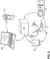
- Fig. 1illustrates an aircraft 10 that may execute embodiments of the invention using aircraft avionics 100, such as a Flight Management System and Flight Guidance System (herein after referred to as "FMS & FGS"). While it is within the scope of the invention for dedicated or specialized aircraft avionics 100 to carry out the different embodiments of the invention, currently practical implementations of the embodiment can use the FMS & FGS currently residing on contemporary aircraft. The FMS & FGS may be programmed to carry out the embodiments of the invention. For purposes of this description the aircraft avionics 100 will be described in the context of the FMS & FGS 100. However, it should be understood that the particular avionics system is not limiting to the invention.
- aircraft avionics 100such as a Flight Management System and Flight Guidance System (herein after referred to as "FMS & FGS"). While it is within the scope of the invention for dedicated or specialized aircraft avionics 100 to carry out the different embodiments of the invention, currently practical implementations of
- the aircraft 10may include a fuselage 12, a nose 26, one or more propulsion engines 16 coupled to the fuselage 12, a cockpit 14 positioned in the fuselage 12, and wings 30 extending outward from the fuselage 12.
- the aircraft 10may further include control surfaces 18 on the wing 30 and empennage 32.
- the control surfaces 18further comprise ailerons 22 which roll the aircraft 10, rudder 20 which turns the aircraft 10 in the yaw direction, engine throttles which can turn the aircraft 10 in the yaw direction if applied asymmetrically, e.g., differential thrust, and speed brakes 24 to slow the airspeed 40 of the aircraft 10.
- asymmetricallye.g., differential thrust, and speed brakes 24 to slow the airspeed 40 of the aircraft 10.
- control surfacesThere are many different types of control surfaces and their use may depend on the size, speed, and complexity of the aircraft 10 on which they are to be used.
- a ground system 404may communicate with the aircraft 10 and other devices including an interface device 400 via a wireless communication link 402, which may be any suitable type of communication such as satellite transmission, radio, etc.
- the ground system 404may be any type of communicating ground system 404 such as an airline control or flight operations department.
- Fig. 2schematically illustrates a FMS & FGS 100 with its surrounding environment.
- the FMS & FGS 100acquires input from flight instruments 140, avionics 150, and interface device 400 in order to control a flight plan 124 (shown schematically as a box) for an aircraft 10.
- the flight instruments 140include, but are not limited to, an altimeter, attitude indicator, airspeed indicator, compass, heading indicator, vertical speed indicator, course deviation indicator, and/or a radio magnetic indicator.
- the avionics 150comprise an electronic systems including, but not limited to, communications, navigation, and the display and management of multiple subsystems.
- the interface device 400may comprise any visual display which collects input from an operator 410 and presents output to the operator 410 and may comprise a control display unit which incorporates a small screen and keyboard or touchscreen.
- the FMS & FGS 100may be used for any aircraft 10 including commercial or military use with single or multiple engines 16.
- the aircraft 10may include but is not limited to a turbine, turbo prop, multi-engine piston, single engine piston and turbofan.
- the FMS & FGShave the primary function of in-flight management of a flight plan 124.
- various sensorssuch as GPS (global positioning system) and INS (inertial navigation system)
- GPSglobal positioning system
- INSintial navigation system
- the flight plan 124is generally determined on the ground, before departure either by the pilot or a professional dispatcher.
- the flight plan 124is entered into the FMS & FGS 100 either by typing it in, selecting it from a saved library of common routes or via a link with the airline dispatch center.
- a principal task of the FMS & FGS 100is to determine the aircraft's position and the accuracy of that position, especially relative to the flight plan.
- Simple FMS & FGS 100use a single sensor, generally GPS, in order to determine position.
- Fig. 3illustrates an exemplary altitude vs distance profile for a flight plan 124 which includes a takeoff phase 330, ascent phase 340, cruise phase 300 typically between 30,000 and 40,000 feet above sea level for contemporary commercial aircraft, then enters a descent phase 310 before a landing phase 320.
- the descent phase 310may be any time that the aircraft 10 descends in altitude other than the landing phase 320. In most cases the descent phase 310 is the transition from the cruise phase 300 to the landing phase 320. For purposes of this description, the descent phase 310 does not include the landing phase 320.
- the landing phase 320comprises a final approach phase 324, landing flare 322, touchdown 326, and roll-out phase 328.
- the landing flare 322is a maneuver or stage during the landing phase 320 of an aircraft 10 and follows the final approach phase 324 and precedes the touchdown 326 and roll-out phases 328 of landing 310.
- the nose 26 of aircraft 10is raised, slowing the descent rate, and the proper attitude is set for touchdown 326.
- the attitudeis set to touch down on all three wheels simultaneously or on just the main landing gear 34.
- the attitudeis set to touchdown 326 on the main landing gear 34.
- the descent 310may comprise a normal, rapid, stair-step, continuous, powered, unpowered descent, idle, or nominal thrust, or any combination of the preceding or any other known descent methods.
- An idle descentmay be utilized where the engine 16 is set at idle, i.e. minimum thrust, then descending the aircraft 10 in altitude towards a landing area or ground 54.
- a nominal thrust descentmay also be implemented during the descent phase 310 where the engine 16 is set at approximately 10% thrust above idle.
- the idle descent or the nominal thrust descentmay be part of a continuous approach descent wherein the altitude of the aircraft 10 changes at a steady rate.
- idle descenthas become the preferred method during the descent phase 310 as the idle descent provides the most efficient utilization of fuel while reducing noise and increasing the life of the engines 16.
- a detriment to an idle descentis that at least one degree of freedom of flight control is lost in that the pilot can no longer use thrust to control the rate of descent.
- the use of thrustincreases fuel consumption, which negates the fuel-saving benefit of an idle descent.
- An embodiment of the inventionaddresses this over-speed condition 120 by placing the aircraft 10 into a slip maneuver 200, which increases aerodynamic drag to slow the aircraft, instead of using thrust and pitch.
- the slip maneuver 200increases the aerodynamic drag of the aircraft 10, which reduces the airspeed 40.
- Applying the slip maneuver 200 during the descent phase 310may be accomplished by the FMS & FGS 100 repeatedly obtaining an airspeed input 116 which corresponds to the airspeed 40 of the aircraft 10.
- the FMS & FGS 100will enter the aircraft 10 into a slip maneuver 200 in order to slow the airspeed 40 of the aircraft 10.
- the descent phase 310continues as before, prior to entering the slip maneuver 200.
- the slip maneuver 200can be used to control the airspeed 40 in alternate descents 310 described above.
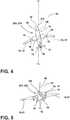
- specific implementations of the slip maneuver 200may be at least one side-slip 202 or forward-slip 204 maneuver.
- the aircraft 10enters the forward-slip maneuver 204 by the FMS & FGS 100 outputting control surface settings to adjust one or more control surface 18 of the aircraft 10. More specifically, the FMS & FGS will control the aircraft 10 such that the aircraft 10 banks and applies opposing rudder or throttle 20 and aileron 22 in order to keep moving straight along the ground track 52.
- the nose 26 of the aircraft 10will point in an alternate direction than the direction of the ground track 52, altered by a slip angle 212.
- the effect of the slip maneuver 204is to rotate the aircraft 10 by the slip angle 212, which is a fraction of a degree, in order to increase the aerodynamic drag to decrease the airspeed 40 of the aircraft 10.
- the slip angle 212 of the forward-slip maneuver 204is 0.2-0.3 degree, although the slip angle 212 may be larger or smaller in alternate embodiments.
- the slip angle 212is the angle between the heading 50 and the ground track 52.
- Heading 50is the direction which the nose 26 is pointed.
- Ground track 52is the path on the surface of the Earth directly below an aircraft 10. In the forward-slip maneuver 204, while the heading 50 of the aircraft changes, the ground track 52 remains the same as before the maneuver.
- a side-slip maneuver 202is when the heading 50 of the aircraft 10 remains the same but the ground track 52 changes due to the movement of control surfaces 18, particularly by adjusting rudder or throttle 20 and ailerons 22 in the opposite directions.
- the horizontal component of liftforces the aircraft 10 to move sideways toward the low wing, creating an angled ground track 52.
- the slip angle 212is a fraction of a degree and the slip maneuver is normally short lived such that the aircraft 10 will not substantially go off the predetermined course. The amount of off track travel can be easily corrected after exiting the slip maneuver 202.
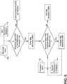
- Fig. 6illustrates a flow chart of exemplary operation of a specific implementation of the FMS & FGS 100 executing the descent algorithm 110.
- the airspeed input 116is repeatedly sent to the FMS & FGS 100 in order to determine if an over-speed condition 120 has occurred.
- the over-speed condition 120occurs if the airspeed 40 of the aircraft 10 is greater than or equal to a predetermined first reference airspeed 112.
- An exemplary first reference air speed 112is a threshold air speed 118 for the given conditions, i.e. a maximum operating speed limit (Vmo) 122. In this embodiment, the first reference airspeed 112 equals five knots less than the maximum operating speed limit (V mo ) 122.
- the descent phase 310continues as planned without a slip maneuver 200. If the airspeed input 116 is equal to or greater than the first reference airspeed 112, then a slip maneuver 200 is entered. Once the aircraft 10 is in the slip maneuver 200, the airspeed input 116 continues to be repeatedly send to the FMS & FGS 100 and compared to a predetermined second reference airspeed 114. Once the airspeed input 116 is determined to be below the second reference airspeed 114, the aircraft 10 will exit the slip maneuver 200. The second reference airspeed 114 is equal to fifteen knots less than V mo 122 in this embodiment. At that time the descent 310 will continue as before the slip maneuver 200.
- the first reference airspeed 112is greater than the second reference airspeed 114.
- the range between the first 112 and second reference airspeed 114is ten knots. In alternate embodiments, the range may be larger, in order to prevent the aircraft from entering and exiting the slip maneuver 200 many times during the descent phase 310.
- the rangemay be selected as appropriate for a particular aircraft 10 and its intended operation. Inherently after the slip maneuver 200 is exited, the airspeed 40 of the aircraft 10 would naturally increase again, it is contemplated that the aircraft 10 may enter a slip maneuver 200 multiple times.
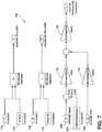
- Fig. 7illustrates an exemplary block diagram of a controller 130 for the FMS & FGS 100.
- the airspeed input 116is repeatedly sent to the FMS & FGS 100 and is compared via a relational operator to the first reference air speed 112. If the airspeed input 116 is equal to or greater than the first reference air speed 112, a slip maneuver 200 is activated. When the airspeed input 116 is determined to be less than the second reference air speed 114, the slip maneuver 200 is deactivated.
- a slip input 206 and slip maneuver 200is input to the FMS & FGS 100 then a slip error 210 is calculated from a summing point.
- the slip error 210determines the forward gain 132 which is summed with a damping gain 134 from the slip rate input 208. The sum of the forward gain 132 and damping gain 134 results in the scaling gain 136 and thus the control surface 18 command is determined.
- the illustrated exemplary controller 130is in no way limiting to the invention disclosed.
- the slip maneuvermay be entered into prior to reaching the over speed condition.
- the descent algorithm being executed by the FMS & FGS to control the descentmay be programmed to monitor the aircraft's speed and at a predetermined value (percentage, threshold, delta, rate of change, etc.) before reaching the operational speed limit, such as Vmo, the FMS & FGS initiates the sending of the appropriate control signals to the appropriate control surfaces, such as rudder or throttle and aileron, to perform the slip maneuver and put the aircraft into the slip condition.
- the FMS & FGScould also be programed to project if/when the aircraft is likely to reach an over speed condition based on the acceleration of the aircraft and the current airspeed. In response to this projection, the FMS & FGS can execute the slip maneuver.
Landscapes
- Engineering & Computer Science (AREA)
- Aviation & Aerospace Engineering (AREA)
- Automation & Control Theory (AREA)
- General Physics & Mathematics (AREA)
- Physics & Mathematics (AREA)
- Remote Sensing (AREA)
- Radar, Positioning & Navigation (AREA)
- Artificial Intelligence (AREA)
- Medical Informatics (AREA)
- Game Theory and Decision Science (AREA)
- Evolutionary Computation (AREA)
- Business, Economics & Management (AREA)
- Health & Medical Sciences (AREA)
- Traffic Control Systems (AREA)
- Tires In General (AREA)
Description
- The descent of an aircraft from a cruise phase to a landing phase may be controlled for a variety of reasons, which may have contradictory goals. When fuel conservation is the primary goal, it is common to perform an idle descent, where the engine is set at idle, i.e. minimum thrust, and controlling the path of descent using control surfaces. During an idle descent, the aircraft may encounter an over-speed condition, which is currently solved by the pilot deploying speed brakes, generating a great amount of noise, which many passengers do not like. For aircraft without speed brakes, other solutions, typically much less desirable, may be used.
- Alternatively, the pilot can apply a pitch input into the aircraft, which change the trajectory and consumes additional fuel and defeating the purpose of the idle descent. Another alternative solution is to utilize one or more of the aircraft avionics, like the Flight Management System and/or Flight Guidance System (FMS & FGS), and leave the engine throttle above idle, at approximately 10% and decrease the throttle when an over-speed condition occurs, which also consumes additional fuel and defeats the purpose of an idle descent.
- "Airplane Flying Handbook", FAA-H-8083-3A, of the U.S Department of Transportation Federal Aviation Administration, and dated 2004, describes on pages 8.10 to 8.11 thereof the use of a slip maneuver by pilots for decreasing the airspeed of an aircraft in an emergency and discloses features generally corresponding to the preamble of
claim 1.EP 2151730 A1 relates to four-dimensional navigation of an aircraft. - The invention relates to a method of automatically controlling the descent phase of an aircraft using aircraft avionics executing a descent algorithm. The aircraft avionics repeatedly receives aircraft airspeed input and compares said airspeed with a first reference airspeed to determine if an over-speed condition has occurred. If an over-speed condition has occurred, the aircraft enters a slip maneuver.
- In the drawings:
Fig. 1 is a perspective view of the aircraft in data communication with a ground system, and which provide an illustrative environment for aspects of the invention.Fig. 2 is a basic illustration of an aircraft avionics systems and its surrounding environment for use in controlling the aircraft.Fig. 3 is an exemplary altitude profile of a flight plan.Fig. 4 is a pictorial view of an aircraft in a forward-slip.Fig. 5 is a pictorial view of an aircraft in a side-slip.Fig. 6 is a flow chart of an aircraft system for controlling the flight of the aircraft in accordance with an exemplary aspect.Fig. 7 is a schematic block diagram of a controller to control the flight path of an aircraft according to an exemplary aspect.Fig. 1 illustrates anaircraft 10 that may execute embodiments of the invention usingaircraft avionics 100, such as a Flight Management System and Flight Guidance System (herein after referred to as "FMS & FGS"). While it is within the scope of the invention for dedicated orspecialized aircraft avionics 100 to carry out the different embodiments of the invention, currently practical implementations of the embodiment can use the FMS & FGS currently residing on contemporary aircraft. The FMS & FGS may be programmed to carry out the embodiments of the invention. For purposes of this description theaircraft avionics 100 will be described in the context of the FMS & FGS 100. However, it should be understood that the particular avionics system is not limiting to the invention.- The
aircraft 10 may include afuselage 12, anose 26, one ormore propulsion engines 16 coupled to thefuselage 12, acockpit 14 positioned in thefuselage 12, andwings 30 extending outward from thefuselage 12. Theaircraft 10 may further includecontrol surfaces 18 on thewing 30 andempennage 32. Thecontrol surfaces 18 further compriseailerons 22 which roll theaircraft 10,rudder 20 which turns theaircraft 10 in the yaw direction, engine throttles which can turn theaircraft 10 in the yaw direction if applied asymmetrically, e.g., differential thrust, andspeed brakes 24 to slow the airspeed 40 of theaircraft 10. There are many different types of control surfaces and their use may depend on the size, speed, and complexity of theaircraft 10 on which they are to be used. - A
ground system 404 may communicate with theaircraft 10 and other devices including aninterface device 400 via awireless communication link 402, which may be any suitable type of communication such as satellite transmission, radio, etc. Theground system 404 may be any type of communicatingground system 404 such as an airline control or flight operations department. Fig. 2 schematically illustrates a FMS & FGS 100 with its surrounding environment. The FMS & FGS 100 acquires input fromflight instruments 140,avionics 150, andinterface device 400 in order to control a flight plan 124 (shown schematically as a box) for anaircraft 10. Theflight instruments 140 include, but are not limited to, an altimeter, attitude indicator, airspeed indicator, compass, heading indicator, vertical speed indicator, course deviation indicator, and/or a radio magnetic indicator. Theavionics 150 comprise an electronic systems including, but not limited to, communications, navigation, and the display and management of multiple subsystems. Theinterface device 400 may comprise any visual display which collects input from anoperator 410 and presents output to theoperator 410 and may comprise a control display unit which incorporates a small screen and keyboard or touchscreen.- The FMS & FGS 100 may be used for any
aircraft 10 including commercial or military use with single ormultiple engines 16. Theaircraft 10 may include but is not limited to a turbine, turbo prop, multi-engine piston, single engine piston and turbofan. - The FMS & FGS have the primary function of in-flight management of a
flight plan 124. Using various sensors, such as GPS (global positioning system) and INS (inertial navigation system), to determine a position of theaircraft 10, the FMS & FGS 100 can guide theaircraft 10 along theflight plan 124. Theflight plan 124 is generally determined on the ground, before departure either by the pilot or a professional dispatcher. Theflight plan 124 is entered into the FMS & FGS 100 either by typing it in, selecting it from a saved library of common routes or via a link with the airline dispatch center. Once in flight, a principal task of the FMS & FGS 100 is to determine the aircraft's position and the accuracy of that position, especially relative to the flight plan. Simple FMS & FGS 100 use a single sensor, generally GPS, in order to determine position. Fig. 3 illustrates an exemplary altitude vs distance profile for aflight plan 124 which includes atakeoff phase 330,ascent phase 340,cruise phase 300 typically between 30,000 and 40,000 feet above sea level for contemporary commercial aircraft, then enters adescent phase 310 before alanding phase 320. Thedescent phase 310 may be any time that theaircraft 10 descends in altitude other than thelanding phase 320. In most cases thedescent phase 310 is the transition from thecruise phase 300 to thelanding phase 320. For purposes of this description, thedescent phase 310 does not include thelanding phase 320. Thelanding phase 320 comprises afinal approach phase 324,landing flare 322,touchdown 326, and roll-outphase 328. Thelanding flare 322 is a maneuver or stage during thelanding phase 320 of anaircraft 10 and follows thefinal approach phase 324 and precedes thetouchdown 326 and roll-outphases 328 oflanding 310. In theflare 322 thenose 26 ofaircraft 10 is raised, slowing the descent rate, and the proper attitude is set fortouchdown 326. In the case of conventional landing gear-equippedaircraft 10 the attitude is set to touch down on all three wheels simultaneously or on just themain landing gear 34. In the case of tricycle gear-equippedaircraft 10 the attitude is set totouchdown 326 on themain landing gear 34.- The
descent 310 may comprise a normal, rapid, stair-step, continuous, powered, unpowered descent, idle, or nominal thrust, or any combination of the preceding or any other known descent methods. An idle descent may be utilized where theengine 16 is set at idle, i.e. minimum thrust, then descending theaircraft 10 in altitude towards a landing area orground 54. A nominal thrust descent may also be implemented during thedescent phase 310 where theengine 16 is set at approximately 10% thrust above idle. The idle descent or the nominal thrust descent may be part of a continuous approach descent wherein the altitude of theaircraft 10 changes at a steady rate. - In the current market, cost pressures are driving aircraft operators to seek fuel, environmental and maintenance savings. Accordingly, idle descent has become the preferred method during the
descent phase 310 as the idle descent provides the most efficient utilization of fuel while reducing noise and increasing the life of theengines 16. A detriment to an idle descent is that at least one degree of freedom of flight control is lost in that the pilot can no longer use thrust to control the rate of descent. The use of thrust increases fuel consumption, which negates the fuel-saving benefit of an idle descent. Unfortunately, during an idle descent, it is common for theaircraft 10 to encounter an airspeed over-speedcondition 120. The current solution is to pitch up theaircraft 10 and increase the thrust to slow the airspeed 40 of theaircraft 10, which negates the fuel savings benefits of the idle descent. An embodiment of the invention addresses thisover-speed condition 120 by placing theaircraft 10 into aslip maneuver 200, which increases aerodynamic drag to slow the aircraft, instead of using thrust and pitch. Theslip maneuver 200 increases the aerodynamic drag of theaircraft 10, which reduces the airspeed 40. Applying theslip maneuver 200 during thedescent phase 310 may be accomplished by the FMS &FGS 100 repeatedly obtaining anairspeed input 116 which corresponds to the airspeed 40 of theaircraft 10. When theaircraft 10 encounters anover-speed condition 120 due to gravitational forces, the FMS &FGS 100 will enter theaircraft 10 into aslip maneuver 200 in order to slow the airspeed 40 of theaircraft 10. Once theslip maneuver 200 is completed and theairspeed 16 is reduced as desired, thedescent phase 310 continues as before, prior to entering theslip maneuver 200. Theslip maneuver 200 can be used to control the airspeed 40 inalternate descents 310 described above. - Referring to
Figs 4 and 5 , specific implementations of theslip maneuver 200 may be at least one side-slip 202 or forward-slip 204 maneuver. Looking first at the forward-slip maneuver 204, theaircraft 10 enters the forward-slip maneuver 204 by the FMS &FGS 100 outputting control surface settings to adjust one ormore control surface 18 of theaircraft 10. More specifically, the FMS & FGS will control theaircraft 10 such that theaircraft 10 banks and applies opposing rudder orthrottle 20 andaileron 22 in order to keep moving straight along theground track 52. Thenose 26 of theaircraft 10 will point in an alternate direction than the direction of theground track 52, altered by aslip angle 212. The effect of the slip maneuver 204 is to rotate theaircraft 10 by theslip angle 212, which is a fraction of a degree, in order to increase the aerodynamic drag to decrease the airspeed 40 of theaircraft 10. In one embodiment, theslip angle 212 of the forward-slip maneuver 204 is 0.2-0.3 degree, although theslip angle 212 may be larger or smaller in alternate embodiments. - The
slip angle 212 is the angle between the heading 50 and theground track 52. Heading 50 is the direction which thenose 26 is pointed.Ground track 52 is the path on the surface of the Earth directly below anaircraft 10. In the forward-slip maneuver 204, while the heading 50 of the aircraft changes, theground track 52 remains the same as before the maneuver. - Referring to
Fig. 5 , a side-slip maneuver 202 is when the heading 50 of theaircraft 10 remains the same but theground track 52 changes due to the movement ofcontrol surfaces 18, particularly by adjusting rudder orthrottle 20 andailerons 22 in the opposite directions. The horizontal component of lift forces theaircraft 10 to move sideways toward the low wing, creating anangled ground track 52. As theslip angle 212 is a fraction of a degree and the slip maneuver is normally short lived such that theaircraft 10 will not substantially go off the predetermined course. The amount of off track travel can be easily corrected after exiting the slip maneuver 202. Fig. 6 illustrates a flow chart of exemplary operation of a specific implementation of the FMS &FGS 100 executing the descent algorithm 110. Theairspeed input 116 is repeatedly sent to the FMS &FGS 100 in order to determine if anover-speed condition 120 has occurred. Theover-speed condition 120 occurs if the airspeed 40 of theaircraft 10 is greater than or equal to a predeterminedfirst reference airspeed 112. An exemplary firstreference air speed 112 is a threshold air speed 118 for the given conditions, i.e. a maximum operating speed limit (Vmo) 122. In this embodiment, thefirst reference airspeed 112 equals five knots less than the maximum operating speed limit (Vmo) 122. If theairspeed input 116 is less than thefirst reference airspeed 112, thedescent phase 310 continues as planned without aslip maneuver 200. If theairspeed input 116 is equal to or greater than thefirst reference airspeed 112, then aslip maneuver 200 is entered. Once theaircraft 10 is in theslip maneuver 200, theairspeed input 116 continues to be repeatedly send to the FMS &FGS 100 and compared to a predeterminedsecond reference airspeed 114. Once theairspeed input 116 is determined to be below thesecond reference airspeed 114, theaircraft 10 will exit theslip maneuver 200. Thesecond reference airspeed 114 is equal to fifteen knots less than Vmo 122 in this embodiment. At that time thedescent 310 will continue as before theslip maneuver 200.- The
first reference airspeed 112 is greater than thesecond reference airspeed 114. The range between the first 112 andsecond reference airspeed 114 is ten knots. In alternate embodiments, the range may be larger, in order to prevent the aircraft from entering and exiting theslip maneuver 200 many times during thedescent phase 310. The range may be selected as appropriate for aparticular aircraft 10 and its intended operation. Inherently after theslip maneuver 200 is exited, the airspeed 40 of theaircraft 10 would naturally increase again, it is contemplated that theaircraft 10 may enter aslip maneuver 200 multiple times. Fig. 7 illustrates an exemplary block diagram of acontroller 130 for the FMS &FGS 100. Theairspeed input 116 is repeatedly sent to the FMS &FGS 100 and is compared via a relational operator to the firstreference air speed 112. If theairspeed input 116 is equal to or greater than the firstreference air speed 112, aslip maneuver 200 is activated. When theairspeed input 116 is determined to be less than the secondreference air speed 114, theslip maneuver 200 is deactivated. Aslip input 206 and slipmaneuver 200 is input to the FMS &FGS 100 then aslip error 210 is calculated from a summing point. Theslip error 210 determines theforward gain 132 which is summed with a dampinggain 134 from theslip rate input 208. The sum of theforward gain 132 and dampinggain 134 results in thescaling gain 136 and thus thecontrol surface 18 command is determined. The illustratedexemplary controller 130 is in no way limiting to the invention disclosed.- In any of the previously described embodiments, the slip maneuver may be entered into prior to reaching the over speed condition. The descent algorithm being executed by the FMS & FGS to control the descent may be programmed to monitor the aircraft's speed and at a predetermined value (percentage, threshold, delta, rate of change, etc.) before reaching the operational speed limit, such as Vmo, the FMS & FGS initiates the sending of the appropriate control signals to the appropriate control surfaces, such as rudder or throttle and aileron, to perform the slip maneuver and put the aircraft into the slip condition. The FMS & FGS could also be programed to project if/when the aircraft is likely to reach an over speed condition based on the acceleration of the aircraft and the current airspeed. In response to this projection, the FMS & FGS can execute the slip maneuver.
- This written description uses examples to disclose the invention, including the best mode, and also to enable any person skilled in the art to practice the invention, including making and using any devices or systems and performing any incorporated methods. The patentable scope of the invention is defined by the claims, and may include other examples that occur to those skilled in the art. Such other examples are intended to be within the scope of the claims if they have structural elements that do not differ from the literal language of the claims, or if they include equivalent structural elements with insubstantial differences from the literal languages of the claims.
Claims (15)
- A method of controlling the descent phase of an aircraft (10),characterized in that the method automatically controls the descent phase of an aircraft (10) using aircraft avionics (100) executing a descent algorithm (110), the method comprising:repeatedly receiving as input to the aircraft avionics (100) an airspeed input (116) indicative of the airspeed of the aircraft (10);comparing by the aircraft avionics (100) the airspeed input (116) to a first reference airspeed (112);determining by the aircraft avionics when the airspeed input (116) indicates an over-speed condition based on the comparison; andplacing the aircraft (10) into a slip maneuver (200) in response to the determined over-speed condition by the aircraft avionics.
- The method of claim 1, further comprising exiting the aircraft (10) from the slip maneuver (200) when the over-speed condition ceases.
- The method of claim 2, further comprising determining the cessation of the over-speed condition by, during the slip maneuver (200):repeatedly receiving as input to a flight management system of the aircraft (10) an airspeed input indicative of the airspeed of the aircraft;comparing by the aircraft avionics (100) the airspeed input to a second reference airspeed (114); anddetermining by the aircraft avionics when the airspeed input indicates an absence of the over-speed condition based on the comparison.
- The method of claim 3, wherein the first reference air speed (112) is greater than the second reference air speed (114).
- The method of claim 4, wherein the first and second reference air speeds (112, 114) differ by at least 10 knots.
- The method of any preceding claim, wherein the first reference air speed (112) is a threshold speed.
- The method of claim 6, wherein the threshold speed is a maximum operating speed limit (Vmo).
- The method of any of claims 1 to 5, wherein the first reference air speed (112) is a speed range.
- The method of any preceding claim, wherein the determining of the over-speed condition comprises the airspeed input (116) exceeding the first reference airspeed (112).
- The method of any preceding claim, further comprising placing the aircraft (10) into the slip maneuver (200) when the over-speed condition occurs during a minimum thrust condition.
- The method of any preceding claim, further comprising placing the aircraft (10) into the slip maneuver (200) when the over-speed condition occurs during an idle descent.
- The method of any preceding claim, wherein the slip maneuver (200) comprises at least one of a side-slip maneuver or a forward-slip maneuver.
- The method of any preceding claim, wherein placing the aircraft (10) into the slip maneuver (200) comprises the aircraft avionics (100) outputting control surface settings to adjust one or more control surfaces of the aircraft and/or outputting engine throttle control signals.
- The method of claim 13, wherein the throttle control signals implement a differential thrust from the aircraft engines.
- The method of either of claims 13 or 14, wherein the control surfaces comprise at least one of a rudder and aileron.
Applications Claiming Priority (1)
| Application Number | Priority Date | Filing Date | Title |
|---|---|---|---|
| US14/581,709US9646505B2 (en) | 2014-12-23 | 2014-12-23 | Method of automatically controlling the descent phase of an aircraft using aircraft avionics executing a descent algorithm |
Publications (2)
| Publication Number | Publication Date |
|---|---|
| EP3037345A1 EP3037345A1 (en) | 2016-06-29 |
| EP3037345B1true EP3037345B1 (en) | 2018-07-04 |
Family
ID=54754515
Family Applications (1)
| Application Number | Title | Priority Date | Filing Date |
|---|---|---|---|
| EP15197006.8AActiveEP3037345B1 (en) | 2014-12-23 | 2015-11-30 | A method of automatically controlling the descent phase of an aircraft using aircraft avionics executing a descent algorithm |
Country Status (6)
| Country | Link |
|---|---|
| US (1) | US9646505B2 (en) |
| EP (1) | EP3037345B1 (en) |
| JP (1) | JP6457923B2 (en) |
| CN (1) | CN105717937B (en) |
| BR (1) | BR102015032182A2 (en) |
| CA (1) | CA2914291C (en) |
Cited By (1)
| Publication number | Priority date | Publication date | Assignee | Title |
|---|---|---|---|---|
| US10228692B2 (en) | 2017-03-27 | 2019-03-12 | Gulfstream Aerospace Corporation | Aircraft flight envelope protection and recovery autopilot |
Families Citing this family (7)
| Publication number | Priority date | Publication date | Assignee | Title |
|---|---|---|---|---|
| EP3514068B1 (en)* | 2016-09-14 | 2021-03-24 | Japan Aerospace Exploration Agency | Aircraft speed information providing system, speed information providing method, and program |
| CN108614571B (en)* | 2018-04-28 | 2021-03-02 | 上海微小卫星工程中心 | Satellite attitude control test method based on optical sensor |
| GB2580374A (en)* | 2019-01-07 | 2020-07-22 | Ge Aviat Systems Ltd | Aircraft airspeed system and method of cross checking airspeed |
| US11586196B2 (en) | 2020-01-22 | 2023-02-21 | Honeywell International Inc. | Approach mode activation monitoring function and automatic activation in an event of pilot incapacitation |
| CN111666672B (en)* | 2020-06-01 | 2023-11-14 | 北京航天自动控制研究所 | Capability assessment method for thrust decline fault of low-thrust engine |
| CN114063637B (en)* | 2021-09-27 | 2022-11-25 | 西安羚控电子科技有限公司 | Large and medium-sized fixed-wing rear three-point type unmanned aerial vehicle ground running control strategy |
| US12234026B2 (en) | 2022-05-18 | 2025-02-25 | Honeywell International Inc. | Aircraft flap malfunction detection and landing assist system and method |
Family Cites Families (18)
| Publication number | Priority date | Publication date | Assignee | Title |
|---|---|---|---|---|
| GB1561650A (en) | 1976-01-29 | 1980-02-27 | Sperry Rand Corp | Aircraft control system |
| US4709336A (en) | 1985-01-09 | 1987-11-24 | Sperry Corporation | Descent flight path control for aircraft |
| US5060889A (en)* | 1989-05-01 | 1991-10-29 | The Boeing Company | Apparatus and methods for maintaining aircraft track angle during an asymmetric flight condition |
| US5833177A (en)* | 1995-05-15 | 1998-11-10 | The Boeing Company | Autopilot/flight director overspeed protection system |
| US6186447B1 (en)* | 1997-11-10 | 2001-02-13 | The Boeing Company | Autothrottle retard rate control system |
| EP1684145B1 (en) | 2005-01-19 | 2013-05-29 | Airbus Operations | Flight management process for an aircraft |
| US7367530B2 (en) | 2005-06-21 | 2008-05-06 | The Boeing Company | Aerospace vehicle yaw generating systems and associated methods |
| FR2915610B1 (en) | 2007-04-24 | 2009-07-10 | Thales Sa | METHOD FOR CALCULATING AN AIRCRAFT APPROACH TRACK TO AN AIRPORT |
| EP2151730A1 (en)* | 2008-08-05 | 2010-02-10 | The Boeing Company | Four-dimensional navigation of an aircraft |
| DE102008044677B4 (en) | 2008-08-28 | 2012-03-22 | Eads Deutschland Gmbh | Air brake for aircraft |
| FR2945513B1 (en) | 2009-05-18 | 2013-02-08 | Airbus France | METHOD AND DEVICE FOR OPTIMIZING THE PERFORMANCE OF AN AIRCRAFT IN THE PRESENCE OF A SIDE DISSYMETRY |
| US8352099B1 (en) | 2009-07-09 | 2013-01-08 | The Boeing Company | Varying engine thrust for directional control of an aircraft experiencing engine thrust asymmetry |
| FR2956512B1 (en)* | 2010-02-16 | 2012-03-09 | Airbus Operations Sas | METHOD AND DEVICE FOR AUTOMATIC PROTECTION OF AN AIRCRAFT AGAINST AN EXCESSIVE DESCENT RATE. |
| US8688363B2 (en) | 2010-04-30 | 2014-04-01 | Honeywell International Inc. | Aircraft systems and methods with active deceleration control |
| EP2423773B1 (en) | 2010-08-24 | 2014-06-25 | The Boeing Company | Four-dimensional guidance of an aircraft |
| US8666567B2 (en) | 2011-03-31 | 2014-03-04 | Honeywell International Inc. | Systems and methods for controlling the speed of an aircraft |
| WO2012145608A1 (en) | 2011-04-20 | 2012-10-26 | Vos David W | Systems and methods for autonomously landing an aircraft |
| FR3003845B1 (en) | 2013-04-02 | 2016-04-15 | Labinal | SYSTEM FOR RECOVERING AND CONVERTING KINETIC ENERGY AND POTENTIAL ENERGY IN ELECTRIC ENERGY FOR AIRCRAFT |
- 2014
- 2014-12-23USUS14/581,709patent/US9646505B2/enactiveActive
- 2015
- 2015-11-30EPEP15197006.8Apatent/EP3037345B1/enactiveActive
- 2015-12-10CACA2914291Apatent/CA2914291C/ennot_activeExpired - Fee Related
- 2015-12-15JPJP2015243706Apatent/JP6457923B2/ennot_activeExpired - Fee Related
- 2015-12-22BRBR102015032182Apatent/BR102015032182A2/ennot_activeApplication Discontinuation
- 2015-12-23CNCN201510975482.7Apatent/CN105717937B/enactiveActive
Non-Patent Citations (1)
| Title |
|---|
| None* |
Cited By (3)
| Publication number | Priority date | Publication date | Assignee | Title |
|---|---|---|---|---|
| US10228692B2 (en) | 2017-03-27 | 2019-03-12 | Gulfstream Aerospace Corporation | Aircraft flight envelope protection and recovery autopilot |
| US10930164B2 (en) | 2017-03-27 | 2021-02-23 | Gulfstream Aerospace Corporation | Aircraft flight envelope protection and recovery autopilot |
| US11580865B2 (en) | 2017-03-27 | 2023-02-14 | Gulfstream Aerospace Corporation | Aircraft flight envelope protection and recovery autopilot |
Also Published As
| Publication number | Publication date |
|---|---|
| CN105717937A (en) | 2016-06-29 |
| EP3037345A1 (en) | 2016-06-29 |
| US9646505B2 (en) | 2017-05-09 |
| CA2914291C (en) | 2018-06-19 |
| CA2914291A1 (en) | 2016-06-23 |
| US20170011639A1 (en) | 2017-01-12 |
| JP2016164060A (en) | 2016-09-08 |
| BR102015032182A2 (en) | 2016-06-28 |
| JP6457923B2 (en) | 2019-01-23 |
| CN105717937B (en) | 2019-07-16 |
Similar Documents
| Publication | Publication Date | Title |
|---|---|---|
| EP3037345B1 (en) | A method of automatically controlling the descent phase of an aircraft using aircraft avionics executing a descent algorithm | |
| US8880247B2 (en) | Method for planning a landing approach of an aircraft, computer program product with a landing approach plan stored thereon, as well as device for planning a landing approach | |
| McLean | Automatic flight control systems | |
| US9132912B2 (en) | Automated take off control system and method | |
| US9472107B2 (en) | Method and device for determining a control set point of an aircraft, associated computer program and aircraft | |
| US8442707B2 (en) | Implementing continuous descent approaches for maximum predictability in aircraft | |
| EP2151730A1 (en) | Four-dimensional navigation of an aircraft | |
| EP3299924B1 (en) | Enhanced take-off system | |
| EP2506107B1 (en) | System for controlling the speed of an aircraft | |
| JP5292314B2 (en) | Flight management system that generates variable thrust cutback at aircraft departure | |
| EP2442199A1 (en) | Method and system for vertical navigation using time-of-arrival control | |
| JP7333696B2 (en) | Optimizing Climb Performance During Takeoff Using Variable Initial Pitch Angle Targets | |
| JP2016164060A5 (en) | ||
| EP3318486A1 (en) | Automatic braking system controller | |
| JP2010521359A (en) | Flight management system that generates variable thrust cutback at aircraft departure | |
| US20100274418A1 (en) | Method for Determining the Quantity of Fuel Taken On Board an Aircraft Making it Possible to Maintain a Time Requirement of the RTA Type | |
| CN109426276B (en) | Automatic command for lift control device | |
| US9815561B2 (en) | Device for regulating the speed of rotation of a rotorcraft rotor, a rotorcraft fitted with such a device, and an associated regulation method | |
| US20240321125A1 (en) | Method of assising an aircraft in landing on a runway and associated system | |
| US20230206774A1 (en) | Method and system for assisting with the approach of an aircraft with a view to landing | |
| KR100472968B1 (en) | Autonomous Take-Off and Landing System for Large-Class Unmanned Airship | |
| Sadraey | Attitude Control Systems | |
| Fisch et al. | Noise-minimal approach trajectories in mountainous areas | |
| Reel | A Flight Simulation Study of the Simultaneous Non Interfering Aircraft Approach |
Legal Events
| Date | Code | Title | Description |
|---|---|---|---|
| PUAI | Public reference made under article 153(3) epc to a published international application that has entered the european phase | Free format text:ORIGINAL CODE: 0009012 | |
| AK | Designated contracting states | Kind code of ref document:A1 Designated state(s):AL AT BE BG CH CY CZ DE DK EE ES FI FR GB GR HR HU IE IS IT LI LT LU LV MC MK MT NL NO PL PT RO RS SE SI SK SM TR | |
| AX | Request for extension of the european patent | Extension state:BA ME | |
| 17P | Request for examination filed | Effective date:20170102 | |
| RBV | Designated contracting states (corrected) | Designated state(s):AL AT BE BG CH CY CZ DE DK EE ES FI FR GB GR HR HU IE IS IT LI LT LU LV MC MK MT NL NO PL PT RO RS SE SI SK SM TR | |
| REG | Reference to a national code | Ref country code:DE Ref legal event code:R079 Ref document number:602015012965 Country of ref document:DE Free format text:PREVIOUS MAIN CLASS: B64C0013180000 Ipc:G08G0005020000 | |
| GRAP | Despatch of communication of intention to grant a patent | Free format text:ORIGINAL CODE: EPIDOSNIGR1 | |
| RIC1 | Information provided on ipc code assigned before grant | Ipc:B64C 13/18 20060101ALI20180130BHEP Ipc:G08G 5/02 20060101AFI20180130BHEP Ipc:G05D 1/06 20060101ALI20180130BHEP Ipc:G05D 1/00 20060101ALI20180130BHEP | |
| INTG | Intention to grant announced | Effective date:20180222 | |
| GRAS | Grant fee paid | Free format text:ORIGINAL CODE: EPIDOSNIGR3 | |
| GRAA | (expected) grant | Free format text:ORIGINAL CODE: 0009210 | |
| AK | Designated contracting states | Kind code of ref document:B1 Designated state(s):AL AT BE BG CH CY CZ DE DK EE ES FI FR GB GR HR HU IE IS IT LI LT LU LV MC MK MT NL NO PL PT RO RS SE SI SK SM TR | |
| REG | Reference to a national code | Ref country code:GB Ref legal event code:FG4D | |
| REG | Reference to a national code | Ref country code:CH Ref legal event code:EP | |
| REG | Reference to a national code | Ref country code:AT Ref legal event code:REF Ref document number:1015336 Country of ref document:AT Kind code of ref document:T Effective date:20180715 | |
| REG | Reference to a national code | Ref country code:IE Ref legal event code:FG4D | |
| REG | Reference to a national code | Ref country code:DE Ref legal event code:R096 Ref document number:602015012965 Country of ref document:DE | |
| REG | Reference to a national code | Ref country code:FR Ref legal event code:PLFP Year of fee payment:4 | |
| REG | Reference to a national code | Ref country code:NL Ref legal event code:MP Effective date:20180704 | |
| REG | Reference to a national code | Ref country code:LT Ref legal event code:MG4D | |
| REG | Reference to a national code | Ref country code:AT Ref legal event code:MK05 Ref document number:1015336 Country of ref document:AT Kind code of ref document:T Effective date:20180704 | |
| PG25 | Lapsed in a contracting state [announced via postgrant information from national office to epo] | Ref country code:NL Free format text:LAPSE BECAUSE OF FAILURE TO SUBMIT A TRANSLATION OF THE DESCRIPTION OR TO PAY THE FEE WITHIN THE PRESCRIBED TIME-LIMIT Effective date:20180704 | |
| PG25 | Lapsed in a contracting state [announced via postgrant information from national office to epo] | Ref country code:CZ Free format text:LAPSE BECAUSE OF FAILURE TO SUBMIT A TRANSLATION OF THE DESCRIPTION OR TO PAY THE FEE WITHIN THE PRESCRIBED TIME-LIMIT Effective date:20180704 Ref country code:BG Free format text:LAPSE BECAUSE OF FAILURE TO SUBMIT A TRANSLATION OF THE DESCRIPTION OR TO PAY THE FEE WITHIN THE PRESCRIBED TIME-LIMIT Effective date:20181004 Ref country code:LT Free format text:LAPSE BECAUSE OF FAILURE TO SUBMIT A TRANSLATION OF THE DESCRIPTION OR TO PAY THE FEE WITHIN THE PRESCRIBED TIME-LIMIT Effective date:20180704 Ref country code:IS Free format text:LAPSE BECAUSE OF FAILURE TO SUBMIT A TRANSLATION OF THE DESCRIPTION OR TO PAY THE FEE WITHIN THE PRESCRIBED TIME-LIMIT Effective date:20181104 Ref country code:PL Free format text:LAPSE BECAUSE OF FAILURE TO SUBMIT A TRANSLATION OF THE DESCRIPTION OR TO PAY THE FEE WITHIN THE PRESCRIBED TIME-LIMIT Effective date:20180704 Ref country code:SE Free format text:LAPSE BECAUSE OF FAILURE TO SUBMIT A TRANSLATION OF THE DESCRIPTION OR TO PAY THE FEE WITHIN THE PRESCRIBED TIME-LIMIT Effective date:20180704 Ref country code:NO Free format text:LAPSE BECAUSE OF FAILURE TO SUBMIT A TRANSLATION OF THE DESCRIPTION OR TO PAY THE FEE WITHIN THE PRESCRIBED TIME-LIMIT Effective date:20181004 Ref country code:FI Free format text:LAPSE BECAUSE OF FAILURE TO SUBMIT A TRANSLATION OF THE DESCRIPTION OR TO PAY THE FEE WITHIN THE PRESCRIBED TIME-LIMIT Effective date:20180704 Ref country code:AT Free format text:LAPSE BECAUSE OF FAILURE TO SUBMIT A TRANSLATION OF THE DESCRIPTION OR TO PAY THE FEE WITHIN THE PRESCRIBED TIME-LIMIT Effective date:20180704 Ref country code:RS Free format text:LAPSE BECAUSE OF FAILURE TO SUBMIT A TRANSLATION OF THE DESCRIPTION OR TO PAY THE FEE WITHIN THE PRESCRIBED TIME-LIMIT Effective date:20180704 Ref country code:GR Free format text:LAPSE BECAUSE OF FAILURE TO SUBMIT A TRANSLATION OF THE DESCRIPTION OR TO PAY THE FEE WITHIN THE PRESCRIBED TIME-LIMIT Effective date:20181005 | |
| PG25 | Lapsed in a contracting state [announced via postgrant information from national office to epo] | Ref country code:ES Free format text:LAPSE BECAUSE OF FAILURE TO SUBMIT A TRANSLATION OF THE DESCRIPTION OR TO PAY THE FEE WITHIN THE PRESCRIBED TIME-LIMIT Effective date:20180704 Ref country code:HR Free format text:LAPSE BECAUSE OF FAILURE TO SUBMIT A TRANSLATION OF THE DESCRIPTION OR TO PAY THE FEE WITHIN THE PRESCRIBED TIME-LIMIT Effective date:20180704 Ref country code:LV Free format text:LAPSE BECAUSE OF FAILURE TO SUBMIT A TRANSLATION OF THE DESCRIPTION OR TO PAY THE FEE WITHIN THE PRESCRIBED TIME-LIMIT Effective date:20180704 Ref country code:AL Free format text:LAPSE BECAUSE OF FAILURE TO SUBMIT A TRANSLATION OF THE DESCRIPTION OR TO PAY THE FEE WITHIN THE PRESCRIBED TIME-LIMIT Effective date:20180704 | |
| REG | Reference to a national code | Ref country code:DE Ref legal event code:R097 Ref document number:602015012965 Country of ref document:DE | |
| PG25 | Lapsed in a contracting state [announced via postgrant information from national office to epo] | Ref country code:EE Free format text:LAPSE BECAUSE OF FAILURE TO SUBMIT A TRANSLATION OF THE DESCRIPTION OR TO PAY THE FEE WITHIN THE PRESCRIBED TIME-LIMIT Effective date:20180704 Ref country code:IT Free format text:LAPSE BECAUSE OF FAILURE TO SUBMIT A TRANSLATION OF THE DESCRIPTION OR TO PAY THE FEE WITHIN THE PRESCRIBED TIME-LIMIT Effective date:20180704 Ref country code:RO Free format text:LAPSE BECAUSE OF FAILURE TO SUBMIT A TRANSLATION OF THE DESCRIPTION OR TO PAY THE FEE WITHIN THE PRESCRIBED TIME-LIMIT Effective date:20180704 | |
| PLBE | No opposition filed within time limit | Free format text:ORIGINAL CODE: 0009261 | |
| STAA | Information on the status of an ep patent application or granted ep patent | Free format text:STATUS: NO OPPOSITION FILED WITHIN TIME LIMIT | |
| PG25 | Lapsed in a contracting state [announced via postgrant information from national office to epo] | Ref country code:SM Free format text:LAPSE BECAUSE OF FAILURE TO SUBMIT A TRANSLATION OF THE DESCRIPTION OR TO PAY THE FEE WITHIN THE PRESCRIBED TIME-LIMIT Effective date:20180704 Ref country code:SK Free format text:LAPSE BECAUSE OF FAILURE TO SUBMIT A TRANSLATION OF THE DESCRIPTION OR TO PAY THE FEE WITHIN THE PRESCRIBED TIME-LIMIT Effective date:20180704 Ref country code:DK Free format text:LAPSE BECAUSE OF FAILURE TO SUBMIT A TRANSLATION OF THE DESCRIPTION OR TO PAY THE FEE WITHIN THE PRESCRIBED TIME-LIMIT Effective date:20180704 | |
| REG | Reference to a national code | Ref country code:DE Ref legal event code:R119 Ref document number:602015012965 Country of ref document:DE | |
| 26N | No opposition filed | Effective date:20190405 | |
| REG | Reference to a national code | Ref country code:CH Ref legal event code:PL | |
| PG25 | Lapsed in a contracting state [announced via postgrant information from national office to epo] | Ref country code:MC Free format text:LAPSE BECAUSE OF FAILURE TO SUBMIT A TRANSLATION OF THE DESCRIPTION OR TO PAY THE FEE WITHIN THE PRESCRIBED TIME-LIMIT Effective date:20180704 Ref country code:LU Free format text:LAPSE BECAUSE OF NON-PAYMENT OF DUE FEES Effective date:20181130 | |
| REG | Reference to a national code | Ref country code:BE Ref legal event code:MM Effective date:20181130 | |
| REG | Reference to a national code | Ref country code:IE Ref legal event code:MM4A | |
| PG25 | Lapsed in a contracting state [announced via postgrant information from national office to epo] | Ref country code:LI Free format text:LAPSE BECAUSE OF NON-PAYMENT OF DUE FEES Effective date:20181130 Ref country code:SI Free format text:LAPSE BECAUSE OF FAILURE TO SUBMIT A TRANSLATION OF THE DESCRIPTION OR TO PAY THE FEE WITHIN THE PRESCRIBED TIME-LIMIT Effective date:20180704 Ref country code:CH Free format text:LAPSE BECAUSE OF NON-PAYMENT OF DUE FEES Effective date:20181130 | |
| PG25 | Lapsed in a contracting state [announced via postgrant information from national office to epo] | Ref country code:DE Free format text:LAPSE BECAUSE OF NON-PAYMENT OF DUE FEES Effective date:20190601 Ref country code:IE Free format text:LAPSE BECAUSE OF NON-PAYMENT OF DUE FEES Effective date:20181130 | |
| PG25 | Lapsed in a contracting state [announced via postgrant information from national office to epo] | Ref country code:BE Free format text:LAPSE BECAUSE OF NON-PAYMENT OF DUE FEES Effective date:20181130 | |
| PG25 | Lapsed in a contracting state [announced via postgrant information from national office to epo] | Ref country code:MT Free format text:LAPSE BECAUSE OF NON-PAYMENT OF DUE FEES Effective date:20181130 | |
| PG25 | Lapsed in a contracting state [announced via postgrant information from national office to epo] | Ref country code:TR Free format text:LAPSE BECAUSE OF FAILURE TO SUBMIT A TRANSLATION OF THE DESCRIPTION OR TO PAY THE FEE WITHIN THE PRESCRIBED TIME-LIMIT Effective date:20180704 | |
| PG25 | Lapsed in a contracting state [announced via postgrant information from national office to epo] | Ref country code:PT Free format text:LAPSE BECAUSE OF FAILURE TO SUBMIT A TRANSLATION OF THE DESCRIPTION OR TO PAY THE FEE WITHIN THE PRESCRIBED TIME-LIMIT Effective date:20180704 | |
| PG25 | Lapsed in a contracting state [announced via postgrant information from national office to epo] | Ref country code:MK Free format text:LAPSE BECAUSE OF NON-PAYMENT OF DUE FEES Effective date:20180704 Ref country code:CY Free format text:LAPSE BECAUSE OF FAILURE TO SUBMIT A TRANSLATION OF THE DESCRIPTION OR TO PAY THE FEE WITHIN THE PRESCRIBED TIME-LIMIT Effective date:20180704 Ref country code:HU Free format text:LAPSE BECAUSE OF FAILURE TO SUBMIT A TRANSLATION OF THE DESCRIPTION OR TO PAY THE FEE WITHIN THE PRESCRIBED TIME-LIMIT; INVALID AB INITIO Effective date:20151130 | |
| P01 | Opt-out of the competence of the unified patent court (upc) registered | Effective date:20230414 | |
| PGFP | Annual fee paid to national office [announced via postgrant information from national office to epo] | Ref country code:GB Payment date:20241022 Year of fee payment:10 | |
| PGFP | Annual fee paid to national office [announced via postgrant information from national office to epo] | Ref country code:FR Payment date:20241022 Year of fee payment:10 |