EP3034054B1 - Wound dressing with a sensor and method for manufacturing the same - Google Patents
Wound dressing with a sensor and method for manufacturing the sameDownload PDFInfo
- Publication number
- EP3034054B1 EP3034054B1EP14198215.7AEP14198215AEP3034054B1EP 3034054 B1EP3034054 B1EP 3034054B1EP 14198215 AEP14198215 AEP 14198215AEP 3034054 B1EP3034054 B1EP 3034054B1
- Authority
- EP
- European Patent Office
- Prior art keywords
- sensor
- wound dressing
- wound
- display
- backing layer
- Prior art date
- Legal status (The legal status is an assumption and is not a legal conclusion. Google has not performed a legal analysis and makes no representation as to the accuracy of the status listed.)
- Not-in-force
Links
Images


Classifications
- A—HUMAN NECESSITIES
- A61—MEDICAL OR VETERINARY SCIENCE; HYGIENE
- A61F—FILTERS IMPLANTABLE INTO BLOOD VESSELS; PROSTHESES; DEVICES PROVIDING PATENCY TO, OR PREVENTING COLLAPSING OF, TUBULAR STRUCTURES OF THE BODY, e.g. STENTS; ORTHOPAEDIC, NURSING OR CONTRACEPTIVE DEVICES; FOMENTATION; TREATMENT OR PROTECTION OF EYES OR EARS; BANDAGES, DRESSINGS OR ABSORBENT PADS; FIRST-AID KITS
- A61F13/00—Bandages or dressings; Absorbent pads
- A61F13/00051—Accessories for dressings
- A61F13/00059—Accessories for dressings provided with visual effects, e.g. printed or colored
- A—HUMAN NECESSITIES
- A61—MEDICAL OR VETERINARY SCIENCE; HYGIENE
- A61F—FILTERS IMPLANTABLE INTO BLOOD VESSELS; PROSTHESES; DEVICES PROVIDING PATENCY TO, OR PREVENTING COLLAPSING OF, TUBULAR STRUCTURES OF THE BODY, e.g. STENTS; ORTHOPAEDIC, NURSING OR CONTRACEPTIVE DEVICES; FOMENTATION; TREATMENT OR PROTECTION OF EYES OR EARS; BANDAGES, DRESSINGS OR ABSORBENT PADS; FIRST-AID KITS
- A61F13/00—Bandages or dressings; Absorbent pads
- A61F13/00051—Accessories for dressings
- A61F13/00055—Saturation indicators
- A—HUMAN NECESSITIES
- A61—MEDICAL OR VETERINARY SCIENCE; HYGIENE
- A61B—DIAGNOSIS; SURGERY; IDENTIFICATION
- A61B5/00—Measuring for diagnostic purposes; Identification of persons
- A—HUMAN NECESSITIES
- A61—MEDICAL OR VETERINARY SCIENCE; HYGIENE
- A61F—FILTERS IMPLANTABLE INTO BLOOD VESSELS; PROSTHESES; DEVICES PROVIDING PATENCY TO, OR PREVENTING COLLAPSING OF, TUBULAR STRUCTURES OF THE BODY, e.g. STENTS; ORTHOPAEDIC, NURSING OR CONTRACEPTIVE DEVICES; FOMENTATION; TREATMENT OR PROTECTION OF EYES OR EARS; BANDAGES, DRESSINGS OR ABSORBENT PADS; FIRST-AID KITS
- A61F13/00—Bandages or dressings; Absorbent pads
- A61F13/00987—Apparatus or processes for manufacturing non-adhesive dressings or bandages
- A—HUMAN NECESSITIES
- A61—MEDICAL OR VETERINARY SCIENCE; HYGIENE
- A61F—FILTERS IMPLANTABLE INTO BLOOD VESSELS; PROSTHESES; DEVICES PROVIDING PATENCY TO, OR PREVENTING COLLAPSING OF, TUBULAR STRUCTURES OF THE BODY, e.g. STENTS; ORTHOPAEDIC, NURSING OR CONTRACEPTIVE DEVICES; FOMENTATION; TREATMENT OR PROTECTION OF EYES OR EARS; BANDAGES, DRESSINGS OR ABSORBENT PADS; FIRST-AID KITS
- A61F13/00—Bandages or dressings; Absorbent pads
- A61F13/01—Non-adhesive bandages or dressings
- A61F13/01021—Non-adhesive bandages or dressings characterised by the structure of the dressing
- A61F13/01029—Non-adhesive bandages or dressings characterised by the structure of the dressing made of multiple layers
- A—HUMAN NECESSITIES
- A61—MEDICAL OR VETERINARY SCIENCE; HYGIENE
- A61F—FILTERS IMPLANTABLE INTO BLOOD VESSELS; PROSTHESES; DEVICES PROVIDING PATENCY TO, OR PREVENTING COLLAPSING OF, TUBULAR STRUCTURES OF THE BODY, e.g. STENTS; ORTHOPAEDIC, NURSING OR CONTRACEPTIVE DEVICES; FOMENTATION; TREATMENT OR PROTECTION OF EYES OR EARS; BANDAGES, DRESSINGS OR ABSORBENT PADS; FIRST-AID KITS
- A61F13/00—Bandages or dressings; Absorbent pads
- A61F13/15—Absorbent pads, e.g. sanitary towels, swabs or tampons for external or internal application to the body; Supporting or fastening means therefor; Tampon applicators
- A61F13/42—Absorbent pads, e.g. sanitary towels, swabs or tampons for external or internal application to the body; Supporting or fastening means therefor; Tampon applicators with wetness indicator or alarm
- A—HUMAN NECESSITIES
- A61—MEDICAL OR VETERINARY SCIENCE; HYGIENE
- A61B—DIAGNOSIS; SURGERY; IDENTIFICATION
- A61B5/00—Measuring for diagnostic purposes; Identification of persons
- A61B5/103—Measuring devices for testing the shape, pattern, colour, size or movement of the body or parts thereof, for diagnostic purposes
- A61B5/11—Measuring movement of the entire body or parts thereof, e.g. head or hand tremor or mobility of a limb
- A61B5/1107—Measuring contraction of parts of the body, e.g. organ or muscle
- A61B5/1109—Measuring contraction of parts of the body, e.g. organ or muscle of wounds, e.g. at the operation site
- A—HUMAN NECESSITIES
- A61—MEDICAL OR VETERINARY SCIENCE; HYGIENE
- A61B—DIAGNOSIS; SURGERY; IDENTIFICATION
- A61B5/00—Measuring for diagnostic purposes; Identification of persons
- A61B5/44—Detecting, measuring or recording for evaluating the integumentary system, e.g. skin, hair or nails
- A61B5/441—Skin evaluation, e.g. for skin disorder diagnosis
- A61B5/445—Evaluating skin irritation or skin trauma, e.g. rash, eczema, wound, bed sore
- A—HUMAN NECESSITIES
- A61—MEDICAL OR VETERINARY SCIENCE; HYGIENE
- A61F—FILTERS IMPLANTABLE INTO BLOOD VESSELS; PROSTHESES; DEVICES PROVIDING PATENCY TO, OR PREVENTING COLLAPSING OF, TUBULAR STRUCTURES OF THE BODY, e.g. STENTS; ORTHOPAEDIC, NURSING OR CONTRACEPTIVE DEVICES; FOMENTATION; TREATMENT OR PROTECTION OF EYES OR EARS; BANDAGES, DRESSINGS OR ABSORBENT PADS; FIRST-AID KITS
- A61F13/00—Bandages or dressings; Absorbent pads
- A61F13/15—Absorbent pads, e.g. sanitary towels, swabs or tampons for external or internal application to the body; Supporting or fastening means therefor; Tampon applicators
- A61F13/42—Absorbent pads, e.g. sanitary towels, swabs or tampons for external or internal application to the body; Supporting or fastening means therefor; Tampon applicators with wetness indicator or alarm
- A61F2013/422—Absorbent pads, e.g. sanitary towels, swabs or tampons for external or internal application to the body; Supporting or fastening means therefor; Tampon applicators with wetness indicator or alarm the alarm being a colour change
- A—HUMAN NECESSITIES
- A61—MEDICAL OR VETERINARY SCIENCE; HYGIENE
- A61F—FILTERS IMPLANTABLE INTO BLOOD VESSELS; PROSTHESES; DEVICES PROVIDING PATENCY TO, OR PREVENTING COLLAPSING OF, TUBULAR STRUCTURES OF THE BODY, e.g. STENTS; ORTHOPAEDIC, NURSING OR CONTRACEPTIVE DEVICES; FOMENTATION; TREATMENT OR PROTECTION OF EYES OR EARS; BANDAGES, DRESSINGS OR ABSORBENT PADS; FIRST-AID KITS
- A61F13/00—Bandages or dressings; Absorbent pads
- A61F13/15—Absorbent pads, e.g. sanitary towels, swabs or tampons for external or internal application to the body; Supporting or fastening means therefor; Tampon applicators
- A61F13/42—Absorbent pads, e.g. sanitary towels, swabs or tampons for external or internal application to the body; Supporting or fastening means therefor; Tampon applicators with wetness indicator or alarm
- A61F2013/424—Absorbent pads, e.g. sanitary towels, swabs or tampons for external or internal application to the body; Supporting or fastening means therefor; Tampon applicators with wetness indicator or alarm having an electronic device
- A—HUMAN NECESSITIES
- A61—MEDICAL OR VETERINARY SCIENCE; HYGIENE
- A61F—FILTERS IMPLANTABLE INTO BLOOD VESSELS; PROSTHESES; DEVICES PROVIDING PATENCY TO, OR PREVENTING COLLAPSING OF, TUBULAR STRUCTURES OF THE BODY, e.g. STENTS; ORTHOPAEDIC, NURSING OR CONTRACEPTIVE DEVICES; FOMENTATION; TREATMENT OR PROTECTION OF EYES OR EARS; BANDAGES, DRESSINGS OR ABSORBENT PADS; FIRST-AID KITS
- A61F13/00—Bandages or dressings; Absorbent pads
- A61F13/15—Absorbent pads, e.g. sanitary towels, swabs or tampons for external or internal application to the body; Supporting or fastening means therefor; Tampon applicators
- A61F13/42—Absorbent pads, e.g. sanitary towels, swabs or tampons for external or internal application to the body; Supporting or fastening means therefor; Tampon applicators with wetness indicator or alarm
- A61F2013/426—Moisture sensitive polymers
Definitions
- the present inventionrelates to a wound dressing. Furthermore the present invention relates to a method for manufacturing a wound dressing.
- Wound dressings for covering woundsare known in various forms from the prior art. When applied to a wound, the dressings cover the wound such that the wound is prevented from being further harmed and may heal under the dressing.
- WO 2012/012286 A1systems and methods are provided for sensing fluid in a dressing on a patient and producing an electrical signal.
- a galvanic cellis used as an electronic detection device. The galvanic cell is placed in the dressing and produces a voltage when the dressing is substantially saturated.
- WO 2013/114273 A1relates to a wound dressing comprising an application surface for application to a wound, an absorbent structure for absorbing exudate discharged from the wound, an intermediate structure located between the application surface and the absorbent structure and arranged to promote distribution of exudate from the application surface to one or a plurality of inlet zones having a limited area in the absorbent structure, and a detection system to detect the extent of the absorbent structure that is wetted by the exudate having penetrated into the absorbent core via the inlet zone or zones.
- appurtenances to wound dressingswhich include: a substrate configured to mechanically or chemically attach to a wound dressing, a transmission unit attached to a surface of the substrate, the transmission unit including circuitry and at least one antenna, the transmission unit configured to transmit a signal, and a projection operably attached to the transmission unit, the projection being of a size and shape to extend into an interior region of the wound dressing and configured to sample a fluid associated with a wound.
- DE 10 2012 211 015 A1discloses a wound dressing having a wound contact area, a wound analyzing area, a backing layer area and a processing electronics, wherein the wound analyzing area is located between the wound contact area and the backing area, wherein the wound analyzing area has a carrier with a sensor on a side facing the wound and a display at a side facing away from the wound, wherein the display is guided through the backing area to the outside, wherein the sensor is arranged to measure a pH or at pOH value and/or another value to survey the wound status in a wound area underneath the wound contact area and wherein the processing electronics is arranged to receive sensor signals from the sensor and to control the display to generate a visualization of the wound status.
- US 2008/0266117 A1discloses a sensor for detecting the presence of fluid in an absorbent article.
- the sensormay include a fluid activated battery. Fluid received in the absorbent article may connect electrodes of the fluid activated battery and cause a voltage to be generated between battery electrodes. The voltage generated between the electrodes may provide power to the sensor circuit.
- the fluid activated batterymay be configured to detect the presence of fluid in the absorbent article and the presence and/or amount of particular substances in the received fluid.
- US 2005/0137542 A1discloses an absorbent article that includes an electro active display.
- the electro active displaymay include an electro chromic composition positioned between the electrodes.
- the electro active displayis configured to create and exhibit an image that contains active features such as moving graphics or color-changing objects. For instance, the electro active display may display an animated cartoon character or a moving vehicle.
- the electro active displaymay also create symbols or words.
- the electro active displaymay be used, for instance, as a wetness indicator or to indicate the presence of a particular substance.
- a wound dressing according to claim 1which comprises at least one sensor and a display, which is adapted to receive data determined by the sensor in form of an electrical signal and to display the received data.
- status information on the wound dressing and/or on the woundare displayed in a direct and easy way on the display.
- the need for indicatorsis satisfied that provide corresponding status information after the dressing is applied to the wound.
- a wound dressing in terms of the present applicationrefers to any wound care article for covering a wound such that the wound is prevented from being further harmed and may heal under the dressing.
- a wound dressingmay e.g. be a sterile pad, a compress, a bandage, an adhesive bandage, like a Band-Aid®, or a plaster.
- the wound dressingcomprises a backing layer.
- the backing layerin one embodiment serves as a cover of the wound dressing, which is not in direct contact with the wound.
- the wound dressingis designed to be in direct contact with the wound.
- the wound dressingis adapted for absorbing wound exudate discharged from a wound.
- the wound dressingis an adhesive bandage comprising a backing layer, an absorbent pad and an adhesive film.
- the wound dressingis self-adhesive.
- the absorbent padis located under the backing layer, wherein the absorbent pad is intended to come in direct contact with a wound and suitable to absorb blood from the wound.
- the backing layerprevents direct contact between the absorbent pad and e.g. a patient's clothing.
- a self-adhesive filmmay be applied to the bottom side of the backing layer or as a backing layer, which laterally extends beyond the absorbent pad. Those sections extending beyond the absorbent pad may be attached to a patient's skin.
- the wound dressingforms a plaster.
- the wound dressingcomprises an absorbent core, a facing layer, and a backing layer, wherein the absorbent core is located between the facing layer and the backing layer.
- placed/located on the backing layerrefers to being placed/located on an exterior surface of the backing layer, i.e. on an exterior surface of the wound dressing.
- Placed/located under the backing layerrefers to being placed/located on an interior surface of the backing layer, i.e. inside the wound dressing.
- Placed/located on the facing layerrefers to being placed/located on an interior surface of the backing layer, i.e. the wound dressing.
- Placed/located under the facing layerrefers to being placed/located on an exterior surface of the backing layer, i.e. the wound dressing, intended to make direct contact with the wound.
- Wound fluid discharged from the wound bedis absorbed by the absorbent core of the dressing through the facing layer. Once the core is saturated, the dressing has to be replaced by a new one. Furthermore, when becoming saturated the dressing may tend to provide leakage of wound fluid.
- a problematic behavior of the absorbent core, particularly of those comprising a superabsorbent,is that the superabsorbent can create a "gel blocking" resulting in blocking of the lateral flow, which negatively influences the filling behavior of the absorbent core.
- indicationmay be provided in time before saturation or leakage of a wound dressing occur.
- a high local moisture contentwhich can be disadvantageous for a wound's healing process, may be determined based on the data provided by the display.
- suitable indicatorswhen it is time to replace a wound dressing.
- even unforeseen complications like "gel blocking"may be resolved in time by replacing the wound dressing.
- Wound dressingsare in general intended as disposable items for reasons of hygiene.
- the wound dressingcomprises a layered structure comprising at least a facing layer, an absorbent core and a backing layer.
- a wide range of suitable structures and materialsmay be used for the wound dressing.
- the absorbent coremay be any structure suitable to absorb exudate from a wound.
- the material of the absorbent corein an embodiment may comprise any one of a group consisting of cellulose, regenerated cellulose, in particular cellulose fluff or regenerated cellulose fluff, air-laid cellulose or air-laid regenerated cellulose, tissue paper, a non-woven, a textile fabric, a foam, an alginate, ALT, and a hydrocolloid or a combination thereof.
- the absorbent coreis produced as a spunlaced web material of 100% pure cellulose or 100% regenerated cellulose.
- the absorbent corecomprises a mixture of pure cellulose or regenerated cellulose and synthetic fibers.
- the absorbent corecomprises a non-woven tamponade or pad containing sodium carboxymethyl cellulose and regenerated cellulose, as it is commercially available under the trade name aquacel® from ConvaTec (Germany) GmbH of Kunststoff, Germany.
- the wound dressingcomprises an absorbent pad, which is suitable to absorb blood from a wound.
- the material of the absorbent padin an embodiment may comprise any one and any combination of the materials listed above as materials of an absorbent core.
- such a structure of the absorbent coremay be used as a carrier layer to accommodate or carry an absorbent substance, in particular a superabsorbent substance.
- the absorbent core of the wound dressing in an embodimentmay be any structure comprising a superabsorbent substance.
- Superabsorbent substances in the sense of the present applicationare materials being able to absorb and retain large volumes of water in aqueous solutions.
- Superabsorbent substances falling into this categoryare for example modified starch, polymerized polyvinyl alcohol (PVA) and polyethylene oxide (PEO) which are all hydrophilic and have a high affinity to water. When chemically or physically cross-linked, these polymers are water-swellable but not water-soluble.
- PVApolymerized polyvinyl alcohol
- PEOpolyethylene oxide
- the superabsorbent substanceis a superabsorbent polymer (SAP), in particular in the form of (granular) particles or fibers.
- SAPsuperabsorbent polymer
- such a SAPis made from polymerization of acrylic acids blended with sodium hydroxide in the presence of an initiated form poly-acrylic acid sodium salt (sometimes referred to a sodium polyacrylate).
- the absorbent core containing SAPcomprises a carrier layer, wherein the superabsorbent polymer is dispersed in the carrier layer.
- the carrier layerin particular may comprise a material selected of a group consisting of tissue paper, a spunlaced polymer, a non-woven fabric, fluff/cellulose, regenerated cellulose as rayon, foam based on different chemistry as polyurethane, alginate, hydrocolloid, carboxymethyl cellulose (CMC) and its derivate and cotton.
- the absorbent core containing SAPcomprises at least two carrier layers, which together with the SAP form the absorbent core.
- the SAPis dispersed on the first layer, then the second layer is put on top and the two layers are consolidated providing a matrix carrying the SAP between the two layers.
- the absorbent corecomprises a carrier layer made of a spunlaced polymer as a non-woven fabric and a granular or fibrous SAP.
- the SAPis in a first step, preferably uniformly, dispersed on a first sheet or layer of the spunlaced nonwoven.
- a second sheet or layer of the spunlaced nonwovenis put on top of the first sheet, such that the SAP is located between the two sheets or layers.
- the SAPis integrated in both layers by applying pressure to this sandwich structure provided.
- pressureBy applying pressure, the two layers of spunlaced polymer are consolidated and the SAP to some extent fills up voids in the spunlaced material.
- the laminate formed this wayis soft and looks like a single uniform layer of material.
- a non-woven fabric in the sense of the present applicationis a material made of at least one layer of fibers that have been formed to a web and consolidated in a next step.
- consolidation of the non-woven fabricmay be achieved by friction and/or cohesion and/or adhesion, for example by needling, felting, spun-lacing, melting or heat embossing.
- a materialwill be considered a non-woven fabric in the sense of the present application once more than 50 % of the mass of its fiber components consist of fibers having a ratio of their length to their diameter of more than 300.
- the materialwill be considered a non-woven fabric in the sense of the present application if this condition is not fulfilled, but if more than 30 % of the mass of its fiber components consist of fibers having a ratio of their length to their diameter of more than 300 and its density is lower than 0.4 g / cm 3 . This is deemed to be equal to EM 29 092.
- An absorbent corein particular an absorbent core having a superabsorbent substance that in the following text may also be denoted as a superabsorbent core, extracts and stores liquid exudates from a wound, to which the wound dressing is applied to.
- the wound dressingfurther comprises a facing layer.
- the wound dressingfurther comprises a backing layer.
- the facing layercomprises a material selected of a group consisting of a non-woven fabric, e.g. containing polyethylene (PE), polyethylene terephthalate (PET), polypropylene (PP), polyamide or polytetrafluoroethylene (PTFE), a perforated sheet, e.g. containing polyethylene (PE), polyethylene terephthalate (PET), polypropylene (PP), poly-amide or polytetrafluoroethylene (PTFE), a perforated sheet laminated on a non-woven fabric, e.g.
- a non-woven fabrice.g. containing polyethylene (PE), polyethylene terephthalate (PET), polypropylene (PP), poly-amide or polytetrafluoroethylene (PTFE), a perforated sheet laminated on a non-woven fabric, e.g.
- PEpolyethylene
- PETpolyethylene terephthalate
- PPpolypropylene
- PTFEpolyamide or polytetrafluoroethylene
- a fine net or screene.g. containing polyethylene (PE), polyethylene terephthalate (PET), polypropylene (PP), polyamide or polytetrafluoroethylene (PTFE), a perforated foam or sheet comprising polyurethane, a perforated material based on silicone or a foam with open cells based on polyurethane or silicone or a combination thereof.
- the facing layercomprises a perforated sheet or film, wherein perforations in the facing layer form a three-dimensional structure in order to reduce the sticking surface between the facing layer and the wound surface and to enhance the contact with the wound.
- the facing layercomprises a non-woven fabric consisting of synthetic and/or cellulose fibers.
- the fibers of a non-woven fabric forming a facing layerare reoriented such that they predominantly extend in a direction perpendicular to the extension of the facing layer. Such a reorientation of the fibers in the non-woven fabric is achieved by orienting the fibers during the fabrication process, in particular during spun-lacing, needling or electrostatic processing.
- the facing layercomprises a density in a range from 0.1 g / cm 3 to 0.6 g / cm 3 .
- the facing layer made of a nonwoven in its unwetted statecomprises an area weight (also denoted as the gram weight, basis weight or grammage) in a range from 8 gsm (g / m 2 ) to 50 gsm (g / m 2 ), preferably in a range from 12 gsm (g / m 2 ) to 30 gsm (g / m 2 ).
- area weightalso denoted as the gram weight, basis weight or grammage
- the facing layercomprises a hydrophobic or hydrophilic surface. This is in particular applicable once the facing layer is brought into direct contact with the wound. Therefore, the facing layer in an embodiment may be coated by non-sticking material, e.g. silicone. In an embodiment, the non-sticking material on the facing layer may be structured to form a pattern with holes on the facing layer.
- non-sticking materiale.g. silicone.
- the non-sticking material on the facing layermay be structured to form a pattern with holes on the facing layer.
- the facing layeris brought into direct contact with the wound (it may then be denoted the contact layer), there may be an embodiment, wherein the wound dressing comprises one or more further layers between the facing layer and the wound.
- the wound dressingcomprises one or more further layers between the facing layer and the wound.
- the backing layerserves as a clothing protection.
- the backing layerthus is advantageously made of a breathable, non-woven fabric or a breathable film enabling breathing of the wound, but preventing wound exudates from exiting the wound dressing and contaminating a patient's clothing.
- the backing layerin particular when made of a non-woven fabric, is hydrophobic.
- the backing layeris a hydrophobic nonwoven based on polypropylene with a hydro head in a range from 40 cm H 2 O to 120 cm H 2 O, preferably in a range from 50 cm H 2 O to 80 cm H 2 O.
- a backing fulfilling this requirement on the one handprovides a good protection of a patient's clothing while on the other hand avoiding bacteria to enter into the wound dressing.
- the hydro head in the sense of the present applicationis the height of a vertical water column standing on and above the surface of the material and which the material can stand against before the water passes through the material to the other side.
- the numbers given for the hydro headare measured according to ISO 811:1981.
- the wound dressingcomprises a backing layer, e.g. a BTBS (breathable textile back sheet), folded such that it prevents side leakage.
- a backing layere.g. a BTBS (breathable textile back sheet)
- An effective prevention of leakagecan be achieved by a tubular arrangement, wherein a circumferential portion of the backing layer is folded around the edges of the absorbent core such that it extends at least partially below the absorbent core and overlaps the facing layer.
- the overlapping portion in direct contact with the facing layeris fixed onto the same, e.g. by gluing.
- backing layerespecially a BTBS backing layer.
- the displayis mounted on or integrated with a backing layer of the wound dressing.
- the displayis generated by a printing process. Since the surface structure of the backing layer is in general not suited for a direct printing, the display in one embodiment is printed on a substrate, which in turn is mounted on or integrated with the backing layer.
- the backing layeris in a first step prepared by applying a substrate, e.g. a plastic layer, onto the backing layer.
- the displayis printed onto the prepared substrate on the backing layer.
- a lacquer layeris printed onto the backing layer in order to smoothen the same.
- a displayis printed on the lacquer.
- the samemay be located on an extra area spaced apart from the absorbent core.
- an additional bandage materiallike a gauze bandage, the extra area with the display still remains visible.
- the displayis mounted on or integrated with a portion of the backing layer extending laterally spaced apart from the absorbent core.
- the displaymay be attached to any suitable surface of the dressing protruding laterally from the wound dressing.
- the displayis based on a conducting polymer, preferably on PEDOT:PSS.
- PEDOTPoly(3,4-ethylenedioxythiophene)
- the electrically conducting form of PEDOTis obtained by chemical doping of the pristine conjugated polymer, and charge neutrality is then maintained by an excess amount of poly(styrene sulfonic acid) (PSS), which is a polyanion.
- PSSpoly(styrene sulfonic acid)
- PSSpoly(styrene sulfonic acid)
- PEDOT:PSSis responsive to electrochemical reduction, wherein not only the color of the material is switched, but also the electronic conductivity.
- the corresponding color change of the materialis utilized in electrochromic displays.
- An electrochromic displayis based on electrochemical reactions on the electrodes. One electrode is reduced and the other is oxidized. Upon changing the oxidation state, the color is changed.
- a conducting polymerallows for a printable display.
- This displaymay be operable at low driving voltages of e.g. a voltage in a range from 1 V to 3 V.
- the displayalso has the advantage of being energy efficient, since it only requires an electric current during update or change of the display. To update the display a charge of only 200 nAh / cm 2 may be needed.
- an updating currentis provided to keep the display in a high contrast mode.
- the displayis further resistant to sterilization methods used for wound dressings, like exposition to ethylene oxide gas.
- the at least one sensoris adapted for determining data on moisture, moisture level, pressure, temperature, and/or pH level.
- Corresponding sensorsprovide an indication of the moisture distribution and level within the wound dressing. Based on these data, the appropriate time for replacement of an almost used up wound dressing as well as status information on the dressing and the wound may be determined. In particular, leakage of the wound dressing can thus be prevented.
- the senoris adapted to measure the moisture level in the wound bed, wherein the sensor is placed under the facing layer.
- data on temperature and pH level of the woundcan provide a suitable basis for conclusions on the healing process of the wound.
- a measurement of the pressure applied to the wound via the dressing and e.g. an additional bandagemay be used to judge whether the applied pressure is too large, too small or suitable.
- the senoris located between the facing layer and the backing layer, wherein the sensor is located at or integrated with the backing layer.
- Temperature and leakage sensorsare in some embodiments located at or integrated with the facing layer.
- a pressure sensormay be either located at or integrated with the facing layer or the backing layer.
- a moisture-detecting sensoris placed wherever a local occurrence or level of moisture is to be determined. Leakage in general occurs at the facing layer, which results in a need to have a sensor located peripherally between the facing layer and the absorbent core. For detection of saturation, the sensor may instead be placed at the backing layer to sense, when the fluid wets through the absorbent core. To be able to detect pattern of local saturation, there is a need to have sensors spread over larger areas, e.g. in a net or matrix shaped pattern. In one embodiment, moisture sensors are distributed according to a 3D matrix pattern over the wound dressing, thus providing information on the 3D distribution of moisture within the dressing.
- Pressure and temperaturemay be measured based on determining changes in resistance.
- the moisturemay be measured by a potential generated due to the contact between two electrodes of the sensor and an electrolytic wound fluid, i.e. wound exudate.
- a measurement of a moisture levelis intended to indicate, when it is time to replace a wound dressing.
- the switching time of the corresponding sensors and displaymay be set on the order of minutes, since the wetting process of an absorbent core, e.g. with superabsorbent particles, is rather slow, i.e. occurs on similar time scales.
- the displayshould be capable to show a corresponding message for about 2 to 7 days, which is the usual period a wound dressing is applied to a wound. It may be beneficial to have an icon, e.g. on the display, that is activated and lights up as soon as the dressing is applied and/or the sensor system/display is activated in order to indicate that the same are working.
- At least one sensordetermines the absolute temperature in order to fulfill the need to indicate and report changes in temperature.
- the sensoris adapted for a temperature range of 32 °C to 43 °C.
- a switch device for altering between the valuesmay be provided for displaying the temperature in both °C as well as °F. Switching time of the sensor and/or display may be on the order of minutes, since the change in temperature is a comparably slow process.
- a sensor for determining the temperatureis located in the center of the dressing close to the surface of the wound.
- a temperature sensoris placed on or under the facing layer in order to determine the temperature of the wound as directly as possible.
- a further parameter of interestis the absolute pressure, in particular the pressure generated by applying the dressing onto the wound. Therefore, in an embodiment of the present invention a pressure-determining sensor is provided, which is e.g. adapted for a pressure range of 18 mmHg to 70 mmHg with a resolution of 5 mmHg, corresponding to a range of 2.4 kPa to 9.3 kPa with a resolution of 0.7 kPa or a range of 0.4 psi to 1.4 psi.
- the pressure measured in mmHgmay e.g. be visualized in steps of 5 mmHg via the display. This enables simpler drive electronics and a smaller number of display segments.
- Switching time for sensor and displaymay beneficially be on the order of seconds, e.g. one second, in order to provide real time information on pressure during fixation of the wound dressing on the wound.
- one sensoris located close to the backing of the dressing, i.e. close to, on or under the backing layer.
- thermistors and thermocouplesare used as temperature sensors.
- Thermistorsmay be NTC (negative temperature coefficient) as well as PTC (positive temperature coefficient).
- printable ink with thermistorsmay be used, e.g. nano silicon based ink with NTC thermistors.
- a printable ink for inkjet printeris used to create a sensitive thermistor.
- the first layer thereofconsists of conductors made of silver and the second layer is made of nickel oxide (NiO) that act as a thermistor due to the semiconducting behavior that changes, when exposed to variations in the temperature.
- thermistorsare applied that can be surface mounted (SMD) using conducting glue.
- the thermistormay beneficially be encapsulated in glass for higher accuracy and lower moisture sensitivity.
- QTC materialswhich change their electrical resistance under pressure, are used in form of an in screen printable ink.
- QTC materialsare based on irregular particles that come close to each other and provide tunneling of electrons between the particles.
- the materials used to create the particlesare e.g. based on Nickel, Copper and Gold. The more particles come close together, the lower the resistance is.
- the senor and/or displayis arranged on a substrate.
- the sensor and the displayare arranged on a common substrate.
- the substrates used for printing on the electronics of the wound dressingare e.g. be PET (polyethylene terephthalate) or PC (polycarbonate).
- the componentsare applied, e.g. printed, to the substrate, which afterwards is fixed to the wound dressing.
- electronic componentsare directly printed on the backing layer, wherein a substrate in form of an extra dielectric layer has been deposited prior to printing in order to smoothen the surface for the printed electronics.
- the substrateis cut out as small as possible in order minimize any interference with the properties of the wound dressing.
- the substrateis a plastic layer printed or laminated onto the backing layer in order to create a surface that is compatible with the electronics. This advantagously kept as small as possible in order to keep influence on the properties of the wound dressing down to a minimum.
- the printed electronicsare printed on top of the plastic layer.
- a large number of detection pointsi.e. sensors, may be used depending on the accuracy needed, for example 50 measure points per 50 cm 2 .
- the concentrationvaries locally, e.g. less in the middle and more around the wound to follow the moisture gradient and the status of the wound exuding. Thereby, a picture indicating the status of wound healing or re-epithelialization may be provided on the display.
- the wound dressingfurthermore comprises a microcontroller and/or a data logger and/or an analog digital converter and/or a communication interface.
- the data determined by a sensor according to the present inventioni.e. the signal provided by such a sensor, may be converted from analog to digital by an analog digital converter.
- a microcontroller and a data loggermay be used.
- a communication interfacemay be used to communicate with external devices and thereby providing access to the data determined by the sensor.
- An example for such a communication interfaceis a RFID device.
- chipsexamples include the C8051 F996 from Silicon Labs, not adapted for wireless communication, or the MLX90129 from Melexis, which can communicate using RFID/NFC.
- chips with a battery assisted passive (BAP) configurationlike the RFID sensor chip ANDY100 from Farsens, may be used.
- Chips adapted for wireless communicationmay harvest energy from an RF beam emitted by a reader and may additionally comprise an auxiliary battery.
- the microcontrolleris mounted using conducting glue and is located outside the dressing next to the display, wherein the microcontroller is mounted on the same substrate as the printed display and/ or sensors.
- a data logger and/or an antennaare mounted in an analogous way. Further electronic devices like data logger, analog digital converter or communication interface may be mounted similarly.
- the wound dressingcomprises a chip, i.e. microcontroller, adapted for wireless communication together with a corresponding antenna.
- Chips adapted for wireless communication with a wireless devicee.g. a smart phone, do not require a battery in the wound dressing, due to power transmittance through an antenna.
- energyis harvested e.g. from the NFC.
- a wireless communicationoffers the additional possibility of easily visualizing the result on exterior displays.
- the wound dressingfurthermore comprises a battery.
- chipsmay be used that cannot communicate wirelessly.
- the batteryis a galvanic cell formed by the sensor, wherein the sensor comprises two electrodes, i.e. an anode and a cathode, which are adapted to be activated by a wound fluid.
- Wound fluidin general consist to 0.9% of NaCl and is therefore suitable as an electrolytic fluid for a galvanic element.
- a galvanic element in terms of the present inventionis every combination of at least two different electrodes and an electrolyte.
- the batteryis a passive battery, e.g. in form of a galvanic element, which is activated by the wound fluid acting as an electrolyte.
- the battery as provided by the wound dressingdoes not comprise any electrolyte per se. Thus, in order to generate voltage, the electrodes have to be exposed to the wound fluid acting as an electrolyte.
- a passive batteryis formed by a sensor comprising two different electrodes.
- the sensorin turn provides a voltage to drive a change of the display.
- the displayis updated by the sensor to indicate that it is time to change the dressing, when wound fluid connects the two electrodes of the battery generating a potential and a corresponding voltage signal is transferred to the display.
- the choice of the electrode materialdetermines the theoretical voltage that can be generated.
- the internal resistanceinfluences the practical output voltage generated from the sensor.
- the capacityis determined by the amount of active material used in the electrode, which needs to contain enough charge carriers to update the display.
- the senoris printed by using a mixture of ink with metal oxides, wherein for cathode and anode different types of oxides are used.
- Materials for the anodemay be zinc provided as a coating on carbon or zinc blended with carbon at different ratios and for the cathode MnO 2 blended with carbon at different ratios or Ag 2 O blended with carbon at different ratios.
- a material combination for the electrodesis zinc in combination with PEDOT:PSS.
- the zinc particlesare mixed with carbon in order to obtain a uniform conductivity in the electrode.
- zinc and silver oxideare used as electrode materials.
- the silver oxidemay preferably be divalent (AgO) or monovalent (Ag 2 O) silver oxide.
- the conductivity of the monovalent silver oxideis however rather poor.
- itmay be mixed with carbon powder. Since for an application according to the present invention with a low energy display no powerful battery is needed, the carbon may instead be mixed with silver oxide.
- Zn/MnO 2 electrodesare used, wherein the MnO 2 is e.g. blended with carbon to achieve a higher conductivity.
- a Fe/AgO combinationis used, providing high reliability, long life and better durability. Iron and silver oxide are mixed in a carbon ink to achieve functionalized electrodes.
- a bio fuel cellis used, which is triggered by the wound fluid.
- This technologyis based on enzyme reactions or bacteria that mimics the interactions found in nature.
- an autonomous batteryis provided. It is advantageous to use an all-printed power source, which is thin and flexible, e.g. based on zinc and manganese dioxide with zinc chloride as an electrolyte.
- the moisture sensorEven in case of embodiments comprising an autonomous battery or antenna as power sources, for the moisture sensor a similar sensor design may be used as for the battery-like sensor concept. In those embodiments, the sensor does not need to generate a certain potential. It is sufficient to measure the change in impedance as the absorbent core is absorbing moisture, wherein an increasing amount of moisture will result in a decrease in impedance.
- the electrodes in the sensorsmay be based on silver, carbon, or conducting polymers, which may be patterned using common printing technologies.
- the electrodesare flat and have a preferably circular, elliptical, rectangular or square shape. In another embodiment, the electrodes are elongated and form closed loops with a preferably circular, elliptical, rectangular or square shape.
- the wound dressingcomprises two or more sensors.
- sensorsmay be formed and placed such that they are exposed to moisture, when a certain level of saturation is reached.
- a sensormay be placed such that the fluid has to come in contact with the same, when the fluid is going to leak out of the wound dressing.
- the wound dressingcomprises at least two sensors, the electrodes of which are arranged concentrically within in a common plane and/or on parallel planes.
- the sensorswill trigger as soon as the liquid reaches a portion of the same.
- activation of the sensors one after anotherprovides information on the dynamical progress of the fluid within the wound dressing.
- the electrodesare elongated, straight and extend parallel to each other within in a common plane and/or on parallel planes.
- a plurality of sensorsare positioned according to a 2D and/or a 3D matrix. Based on the data gained by those sensor are 2D or 3D pictures of the moisture distribution and its progress within the wound dressing may be provided on the display.
- the absorbent coreis formed by at least three absorbent sub-layers, wherein at least two sensors are arranged between different sub-layers. Thereby a complex 3D distribution of sensors within the dressing is implemented.
- a method for manufacturing a wound dressingcomprising the steps of printing a display, which is adapted to receive data determined by at least one sensor in form of an electrical signal and to display the received data, onto the wound dressing and providing the at least one sensor.
- the wound dressingmay be provided according a known methods for manufacturing.
- the wound dressingis prepared by applying a substrate onto the same and the display is printed onto the prepared substrate.
- One embodiment of a method for manufacturing a wound dressing according to the present inventioncomprises the steps of providing an absorbent core, providing a facing layer, providing a backing layer, and locating the absorbent core between the facing layer and the backing layer, preparing the backing layer by applying a substrate onto the backing layer, printing a display, which is adapted to receive data determined by at least one sensor in form of an electrical signal and to display the received data, onto the prepared substrate and providing the at least one sensor.
- Providing the sensormay include locating the same at or integrated with the facing layer, the backing layer or the absorbent core.
- the backing layeris prepared and the display is printed before the absorbent core is located between the facing layer and the backing layer.
- the sensoris printed on the same substrate as the display.
- a further substrateis applied to the backing layer or the facing layer and the sensor is printed onto the further substrate.
- the absorbent core providedis formed by sub-layers, wherein at least one sub-layer is prepared by applying a substrate to the sub-layer and the sensor is printed onto the prepared substrate.
- a first embodiment of a wound dressing 1comprising features of the invention is schematically depicted.
- Figure 1shows a schematic top view of the top side of a wound dressing 1 according to the present invention.
- the top surfaceis formed by a backing layer 4 with a display 8 mounted thereon.
- the opposite surface, i.e. the bottom surface, of the wound dressing 1 of figure 1is shown.
- the bottom surfaceis formed a facing layer 3.
- FIG 3an alternative embodiment of a wound dressing 1 according to the present invention is shown, wherein the display 8 is mounted on or integrated within the top side of a portion 4' of the backing layer extending laterally spaced apart from the absorbent core 2 of the dressing 1.
- the portion 4' shown in figure 3is arranged along a long side of the rectangular backing layer 4.
- portion 4'may be positioned along any other side of backing layer 4.
- a display mounted on the backing layer 4 according to figure 1may be covered by the same.
- a display 8 located on an extra portion of the backing layer 4remains visible, even if the portion of the wound dressing 1 covering the wound is wrapped.
- the displaymay be placed on the top or the bottom side of the portion 4'. Located on the bottom side, the same may be folded around such that the top side rests on the gauze bandage, where it may be additionally fixed. Thus, the display 8 will be easily visible on top of the gauze bandage.
- the display 8may be placed on any arbitrary kind of substrate attached to the wound dressing 1 and laterally projecting from the same, such that the display 8 remains visible even if the rest of the wound dressing 1 is covered by additional dressing material.
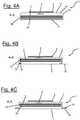
- the wound dressing 1consists of a layered structure which is best understood when considered with reference to the cross-sectional drawings of figures 4A, 4B and 4C , showing three alternative embodiments of the layered structures comprised by the wound dressing shown in figures 1 and 2 .
- the wound dressing 1 of figure 4Acomprises an absorbent core 2, which in this particular embodiment has two sub-layers 2a, 2b made of tissue paper with a superabsorbent polymer in the form of granular particles dispersed between the two sub-layers 2a, 2b.
- the two sub-layerstogether form the carrier layer of the absorbent core.
- the superabsorbent particlesare dispersed on a first sub-layer 2b thereof and then the second sub-layer 2a is consolidated on top of the first sub-layer 2b providing a fixation of the superabsorbent particles.
- the absorbent core 2is wrapped or enveloped in a pouch formed by a facing layer 3 and a backing layer 4.
- the facing layer 3 in this particular embodimentis made of a white hydrophilic non-woven fabric consisting of polypropylene fibers in order to provide a good transport of exudate from a wound to the absorbent core 2.
- the backing layer 4serves as a clothing protection and is made of a green breathable, hydrophobic non-woven fabric based on polypropylene.
- the non-wovenhas a hydro head of 50 cm / H 2 O. This backing layer 4 allows breathing of the wound while simultaneously preventing wound exudates from exiting the wound dressing and contaminating a patient's clothing.
- a moisture determining sensor 5is placed under the backing layer 4 .
- This sensor 5is in contact with the absorbent core 2.
- the sensor 5provides a corresponding voltage signal to the display 8.
- the display 8is updated and indicates that it is time to replace the wound dressing 1 before it is completely saturated such that no further wound fluid is absorbed and the healing process may be negatively influenced.
- the facing layer 3 and the backing layer 4have been joint together by two seams 18, 19 extending above the absorbent core.
- the facing layer 3has been folded in parallel to its long edges such that it also extends above the absorbent core 2 and it partly covers the top surface of the absorbent core 2. Furthermore, the facing layer 3 entirely covers the bottom surface of the absorbent core 2.
- a location of the seams in an area above the absorbent core 2, i.e. in a position where the facing layer 3 and the backing layer 4 overlap above the absorbent core 2,has the advantage that no reddening due to stiff edges along the long side of the wound dressing 1 occur.
- the wound dressing 1When considered in a cross-section along the line A-A of figure 2 the wound dressing 1 thus has a tubular structure as shown in figure 4A .
- sensors 5e.g. moisture sensors
- the sensors 5may be placed between both layers 2a, 2b.
- the sensors 5may be placed between different core layers, i.e. on different levels in the wound dressing 1.
- Sensors 5 distributed in three dimension over the wound dressing 1, e.g. between different core layers,allow to gain and display information on the development of the saturation status and the moisture distribution in 3D.
- a wound moisture level detection sensor 5may be provided detecting the moisture degree in different areas of the wound dressing corresponding to different areas of the wound as well as around the same.
- the moisture levelmay be determined by impedance measurements and e.g. translated into microgram/cm 2 or similar.
- FIG 4Ban embodiment of the wound dressing 1'with an alternative arrangement of the layered structure is shown.
- the cross-sectional view along a line corresponding to the line A-A of figure 2again illustrates a tubular structure.
- the backing layer 4has been folded in parallel to its long edges such that it extends beneath the absorbent core 2 and partly covers the bottom surface of the absorbent core 2. Furthermore, the backing layer 4 entirely covers the top surface of the absorbent core 2.
- the embodiment of figure 4Bavoids reddening due to stiff edges along the long side of the wound dressing 1' occur. Furthermore, the tubular structure of the breathable, hydrophobic backing layer 4, preferably made of a BTBS material, effectively minimizes the risk of a lateral leakage of wound fluid.
- figure 4Cshows a standard arrangement for the connection of backing layer 4 and facing layer 3 attached to each other via overlapping seams 18, 19 extending circumferentially around the absorbent core 2.
- the present inventionmay be advantageously applied even to those standard wound dressings 1".
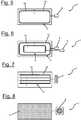
- Figure 5shows an embodiment of the invention with a single sensor 5 adapted as a leakage sensor located under the facing layer.
- the sensor 5is electrically conductive interconnected with a display 8.
- This sensor 5may e.g. be applied to any wound dressing of figures 4A to 4C .
- the backing layer 4consist of a hydrophobic sandwich material, while the facing layer 3 is made of a hydrophilic sandwich material.
- a BTBS back facing 4 with a reversed tube design as shown in figure 4Bmay be used.
- the sensor 5comprises an anode 15 and a cathode 16 extending parallel to each other around the edges of an imaginary rectangle.
- the electrodes 15, 16comprise a line structure, which extends parallel and spaced apart from the edge of the wound dressing 1.
- the electrodesmay be placed up to 50 mm from the edge.
- the galvanic element constituted by the anode 15, the cathode 16 and the electrolytic wound fluidwill be activated and a corresponding potential is generated.
- the resulting voltage signalwill update the display 8.
- the display 8may show a percentage value of the saturation degree of the dressing 1, depending on the position and size of the sensor 5 e.g. 70%, 80%, 90% or up to 100%.
- the sensor 5is preferably arranged such that the display 8 indicates a saturation degree sufficiently below 100% to indicate in time that it is time to change the dressing 1.
- the embodimentcorresponds to the one according to figure 5 except for the fact that in figure 6 two concentrically arranged sensors 5 and 6 are provided. Both sensors 5 and 6 are adapted for moisture determination and designed as galvanic elements to be activated by wound fluid.
- the first, inner sensor 6may be located spaced apart from the edge of the wound dressing 1 such that the enclosed area corresponds to about 30 % to 60 % of the absorbent core area, while the second, outer sensor 5 may enclose about 70 % to almost 100 % of the absorbent core area.
- the inner sensor 6will in general be activated first, giving a progress report of the saturation status of the dressing 1.
- the outer sensor 5When the wound fluid spread, the outer sensor 5 will ultimately be activated, indicating that the dressing 1 has to be replaced soon.
- the result of the two sensors 5, 6may be displayed in the same segment of the display 8. They may alternatively be displayed in different segments of the display 8 or there may be provided more than one display 8, thus displaying every result on a different display 8.
- the embodiment of figure 6provides more information regarding need for change of the dressing 1, in particular about the progress of saturation. Furthermore, it may allow for a better understanding, when maceration starts.
- FIG. 7is a schematic diagram of a sensor arrangement according to the present invention with four identical straight strip-like sensors 5 arranged parallel to each other. Those sensors may be placed on or under the backing layer 4 of a wound dressing 1. There may be more or less stripes provided depending on necessity, e.g. 4 to 10 stripes. Each stripe comprises an anode 15 and a cathode 16, extending parallel too each other. Arranged at the backing layer 4 of the dressing 1, those sensor stripes are provided for detecting a strike through of wound fluid, especially if the backing layer 4 comprises hydrophilic materials. When the fluid has spread upwards through the dressing 1 and reaches the backing layer 4, each single sensor 5 will send a signal to the display 8 as soon as it is activated by contact with the electrolytic wound fluid.
- the display 8provides a light for every sensor 5.
- the display 8comprises no light sources, but is based on a change of contrast, e.g. the color changes from a light blue to a deep blue.
- the display 8may provide a color changing segment for each sensor 5.
- the lights in the display 8will be turned on one by one, when the fluid strikes through, indicating an immediate need for replacement of the dressing 1. This sensor arrangement provides for a better understanding, when the dressing is filled up and when maceration starts.
- the sensor arrangements as shown in figures 5, 6, and 7may also be combined with each other.
- FIG 8an embodiment of a combined saturation and leakage sensor 5 based on a net-like structure is shown.
- the net 5may comprise a plurality of single sensors arranged at the knots of the net 5.
- the net structuremay be formed by a single sensor 5, i.e. every thread of the net is formed by a stripe comprising two electrodes 15, 16.
- the net 5as a matrix structure, from knowing which columns and which rows have been activated, it may be derived, where the wound fluid spreads over the net area.
- This embodimentis based on a chip solution with an active battery (not shown), wherein the sensor(s) 5 measure local impedances.
- the mesh sizemay be adapted as needed.
- the chipreceives those signals on impedance and converts the same to the display 8.
- the net 5may be placed above or below a portion of or the complete backing layer 4 and/or above or below a portion of or the complete facing layer 3.
- the covered areamay e.g. reach from about 40% up to 90% of the backing layer 4 and/or facing layer 3.
- a smaller area covered by the net 5requires a smaller battery capacity and thus allows for cheaper solution, while a larger area gives a more complete picture of the dressing status.
- This sensor 5may show a real time picture of the saturation degree in the dressing 1, which helps the nursing staff to understand what is happening in the wound due to maceration and to judge when it is time to replace the dressing 1.
- the resultsmay be displayed on a display 8 as an e.g. color-coded picture of the real time distribution of the saturation degree over the complete net area or as a %-value for the complete net 5.
- the sensor 5may detect the moisture level in different areas of the wound and around the wound. This information, when displayed by the display 8, may help a specialist nurse to understand the moisture status in the wound.
- FIGs 9A and 9Billustrate the method of detecting moisture via a sensor 5 formed as a galvanic element.
- a single sensor 5comprising an anode 15 and a cathode 16 is shown, both electrodes in the form of flat rectangular elements.
- the display 8indicates nothing.
- wound fluid 17spreads between the anode 15 and cathode 16
- an electrical contactis established and based on the resulting potential a voltage signal is transferred to the display 8.
- the display 8is updated and indicates that a certain saturation level has been reached.
- the displaymay e.g. indicate that the dressing 1 is almost entirely saturated and must be replaced soon.
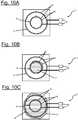
- FIGS 10A to 10Ba detection and determination method for a sensor arrangement corresponding to the one shown in Figure 6 is illustrated.
- a schematic diagram of two concentrically aligned circular shaped sensors 5, 6is shown, wherein the fluid may enter in the middle and then diffuse laterally towards the sensors 5, 6.
- the sensors 5, 6are formed as galvanic elements. As long as no electrolytic fluid has reached any of the electrodes 15, 16, no signal is transferred to the display 8. Again, signals of the two sensors 5, 6 may be displayed in the same segment of a display, in different segments of the same or even on different displays. As soon as wound fluid 17 has reached the first sensor 6, the corresponding galvanic element is activated and on display 8 an information, e.g.
- a %-valueis shown indication the saturation level corresponding to the first sensor 6.
- exposure of the inner rings to the fluid 17may result in triggering a first level note of "50%" on display 8.
- a second information displayed on display 8e.g. a %-value of the saturation level corresponding to the second sensor 5.
- "100%”may be shown on the display 8, indicating an immediate need for replacing the wound dressing 1.
- the second informationmay be shown in addition to the first one or replace the first one. Thereby, information on the moisture distribution over time is provided.
- FIG. 11Ashows a schematic top view of the top side of an adhesive bandage 1 according to the present invention.
- the top surfaceis formed by a backing layer 4 with a display 8 mounted thereon.
- the adhesive bandage 1 of figure 11Bwhich shows a schematic cross-sectional view along line B-B of figure 11A , comprises a backing layer 4.
- On the backing layer 4a display 8 is mounted, under the backing layer 4 an absorbent pad 20 is located.
- the bottom side of the backing layer 4, which laterally extends beyond the absorbent pad 20,is provided with a self-adhesive film 21.
- a sensor 5is located between the backing layer 4 and the absorbent pad 20.
- the sensor 5is e.g. a moisture determining sensor. This sensor 5 is in contact with the absorbent pad 20 and provides a corresponding voltage signal to the display 8, when fluid leaks from the absorbent pad 20.
- the display 8is updated and indicates that it is time to replace the adhesive bandage 1.
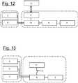
- Figure 12shows a diagram of a circuit comprising a chip, i.e. microcontroller 9, that wirelessly communicates with and harvests energy from an external reader 12, e.g. a RF reader, when it is time for a measurement. Therefore, an antenna 11 is provided for communication between the external reader 12 and the microcontroller 9 via a data logger 10. There may also be analog digital converter (not shown) provided for converting analog sensor signals to digital data. There are two sensors 5 and 6 provided within a wound dressing 1, e.g. a pressure and a temperature sensor, providing information on the temperature and applied pressure via date logger 10 and microcontroller 9 to the display 8. A moisture sensor may alternatively or additionally be provided at the same location as sensors 5 and 6 within the circuit.
- a pressure and a temperature sensore.g. a pressure and a temperature sensor
- the resultcan additionally be displayed on an external reader 12 such as a smart phone.
- an external reader 12such as a smart phone.
- Figure 13shows an alternative embodiment of a circuit according to the present invention.
- the circuit of figure 13uses a printed battery 13 as an energy source for power supply.
- the microcontroller 9performs the measurements on the sensors 5, 6, 7 and displays the result on the display 8.
- This circuitprovides a triggering function via switch 14 in order ensure for the battery 13 to last the shelf time needed.
- a time triggering functionmay be implemented by starting the circuit when the wound dressing 1 is mounted and then showing the results at specific times/time intervals or the result is displayed, when activated via an additional activation means like a push button.
- three sensors 5, 6, 7are provided, which are e.g. a pressure, a temperature as well as a moisture sensor.
Landscapes
- Health & Medical Sciences (AREA)
- Life Sciences & Earth Sciences (AREA)
- Engineering & Computer Science (AREA)
- Biomedical Technology (AREA)
- Heart & Thoracic Surgery (AREA)
- Animal Behavior & Ethology (AREA)
- General Health & Medical Sciences (AREA)
- Public Health (AREA)
- Veterinary Medicine (AREA)
- Vascular Medicine (AREA)
- Molecular Biology (AREA)
- Physics & Mathematics (AREA)
- Biophysics (AREA)
- Pathology (AREA)
- Medical Informatics (AREA)
- Surgery (AREA)
- Epidemiology (AREA)
- Manufacturing & Machinery (AREA)
- Dermatology (AREA)
- Materials For Medical Uses (AREA)
Description
- The present invention relates to a wound dressing. Furthermore the present invention relates to a method for manufacturing a wound dressing.
- Wound dressings for covering wounds are known in various forms from the prior art. When applied to a wound, the dressings cover the wound such that the wound is prevented from being further harmed and may heal under the dressing.
- Once a dressing is applied onto a wound, information on the status neither of the dressing nor of the healing are on hand, but have to be estimated based on experience. However, this has proven to be disadvantageous, especially in cases wherein unforeseen complications occur.
- Thus, there is a need for gaining information on the status of the dressing and/or the status of the wound healing, even when a dressing is in place on a wound.
- In
WO 2012/012286 A1 , systems and methods are provided for sensing fluid in a dressing on a patient and producing an electrical signal. In one instance, a galvanic cell is used as an electronic detection device. The galvanic cell is placed in the dressing and produces a voltage when the dressing is substantially saturated. WO 2013/114273 A1 relates to a wound dressing comprising an application surface for application to a wound, an absorbent structure for absorbing exudate discharged from the wound, an intermediate structure located between the application surface and the absorbent structure and arranged to promote distribution of exudate from the application surface to one or a plurality of inlet zones having a limited area in the absorbent structure, and a detection system to detect the extent of the absorbent structure that is wetted by the exudate having penetrated into the absorbent core via the inlet zone or zones.- In
US 2013/0274629 A1 , appurtenances to wound dressings are described, which include: a substrate configured to mechanically or chemically attach to a wound dressing, a transmission unit attached to a surface of the substrate, the transmission unit including circuitry and at least one antenna, the transmission unit configured to transmit a signal, and a projection operably attached to the transmission unit, the projection being of a size and shape to extend into an interior region of the wound dressing and configured to sample a fluid associated with a wound. DE 10 2012 211 015 A1US 2008/0266117 A1 discloses a sensor for detecting the presence of fluid in an absorbent article. The sensor may include a fluid activated battery. Fluid received in the absorbent article may connect electrodes of the fluid activated battery and cause a voltage to be generated between battery electrodes. The voltage generated between the electrodes may provide power to the sensor circuit. In one embodiment, the fluid activated battery may be configured to detect the presence of fluid in the absorbent article and the presence and/or amount of particular substances in the received fluid.US 2005/0137542 A1 discloses an absorbent article that includes an electro active display. The electro active display may include an electro chromic composition positioned between the electrodes. The electro active display is configured to create and exhibit an image that contains active features such as moving graphics or color-changing objects. For instance, the electro active display may display an animated cartoon character or a moving vehicle. The electro active display may also create symbols or words. When combined with sensors, a power source, and the proper circuitry, the electro active display may be used, for instance, as a wetness indicator or to indicate the presence of a particular substance.- When compared to the prior art it is an object of the present invention to provide an improved wound dressing, which is capable to provide status information on the wound dressing and/or on the wound in an easy and direct way of handling.
- The above object is solved by a wound dressing according to
claim 1, which comprises at least one sensor and a display, which is adapted to receive data determined by the sensor in form of an electrical signal and to display the received data. - With a wound dressing according to the present invention status information on the wound dressing and/or on the wound are displayed in a direct and easy way on the display. Thus, the need for indicators is satisfied that provide corresponding status information after the dressing is applied to the wound.
- A wound dressing in terms of the present application refers to any wound care article for covering a wound such that the wound is prevented from being further harmed and may heal under the dressing. A wound dressing may e.g. be a sterile pad, a compress, a bandage, an adhesive bandage, like a Band-Aid®, or a plaster.
- The wound dressing comprises a backing layer. When the wound dressing is applied to a wound, the backing layer in one embodiment serves as a cover of the wound dressing, which is not in direct contact with the wound.
- In an embodiment, the wound dressing is designed to be in direct contact with the wound. In one embodiment, according to the present invention, the wound dressing is adapted for absorbing wound exudate discharged from a wound.
- In an embodiment according to the present invention, the wound dressing is an adhesive bandage comprising a backing layer, an absorbent pad and an adhesive film. In this embodiment the wound dressing is self-adhesive. In an embodiment, the absorbent pad is located under the backing layer, wherein the absorbent pad is intended to come in direct contact with a wound and suitable to absorb blood from the wound. The backing layer prevents direct contact between the absorbent pad and e.g. a patient's clothing. For example a self-adhesive film may be applied to the bottom side of the backing layer or as a backing layer, which laterally extends beyond the absorbent pad. Those sections extending beyond the absorbent pad may be attached to a patient's skin. In a particular embodiment the wound dressing forms a plaster.
- The wound dressing comprises an absorbent core, a facing layer, and a backing layer, wherein the absorbent core is located between the facing layer and the backing layer.
- In the following placed/located on the backing layer refers to being placed/located on an exterior surface of the backing layer, i.e. on an exterior surface of the wound dressing. Placed/located under the backing layer refers to being placed/located on an interior surface of the backing layer, i.e. inside the wound dressing. Placed/located on the facing layer refers to being placed/located on an interior surface of the backing layer, i.e. the wound dressing. Placed/located under the facing layer refers to being placed/located on an exterior surface of the backing layer, i.e. the wound dressing, intended to make direct contact with the wound.
- Wound fluid discharged from the wound bed is absorbed by the absorbent core of the dressing through the facing layer. Once the core is saturated, the dressing has to be replaced by a new one. Furthermore, when becoming saturated the dressing may tend to provide leakage of wound fluid. A problematic behavior of the absorbent core, particularly of those comprising a superabsorbent, is that the superabsorbent can create a "gel blocking" resulting in blocking of the lateral flow, which negatively influences the filling behavior of the absorbent core.
- By a wound dressing according to the present invention indication may be provided in time before saturation or leakage of a wound dressing occur. In addition, a high local moisture content, which can be disadvantageous for a wound's healing process, may be determined based on the data provided by the display. Thus, it may be easily judged on basis of suitable indicators, when it is time to replace a wound dressing. In particular, even unforeseen complications like "gel blocking" may be resolved in time by replacing the wound dressing.
- Wound dressings are in general intended as disposable items for reasons of hygiene. The wound dressing comprises a layered structure comprising at least a facing layer, an absorbent core and a backing layer. A wide range of suitable structures and materials may be used for the wound dressing.
- In an embodiment, the absorbent core may be any structure suitable to absorb exudate from a wound. The material of the absorbent core in an embodiment may comprise any one of a group consisting of cellulose, regenerated cellulose, in particular cellulose fluff or regenerated cellulose fluff, air-laid cellulose or air-laid regenerated cellulose, tissue paper, a non-woven, a textile fabric, a foam, an alginate, ALT, and a hydrocolloid or a combination thereof. In one embodiment, the absorbent core is produced as a spunlaced web material of 100% pure cellulose or 100% regenerated cellulose. In another embodiment the absorbent core comprises a mixture of pure cellulose or regenerated cellulose and synthetic fibers. In yet another embodiment the absorbent core comprises a non-woven tamponade or pad containing sodium carboxymethyl cellulose and regenerated cellulose, as it is commercially available under the trade name aquacel® from ConvaTec (Germany) GmbH of Munich, Germany.
- In one embodiment of the present invention, the wound dressing comprises an absorbent pad, which is suitable to absorb blood from a wound. The material of the absorbent pad in an embodiment may comprise any one and any combination of the materials listed above as materials of an absorbent core.
- In an embodiment of the invention, such a structure of the absorbent core may be used as a carrier layer to accommodate or carry an absorbent substance, in particular a superabsorbent substance.
- The absorbent core of the wound dressing in an embodiment may be any structure comprising a superabsorbent substance. Superabsorbent substances in the sense of the present application are materials being able to absorb and retain large volumes of water in aqueous solutions. Superabsorbent substances falling into this category are for example modified starch, polymerized polyvinyl alcohol (PVA) and polyethylene oxide (PEO) which are all hydrophilic and have a high affinity to water. When chemically or physically cross-linked, these polymers are water-swellable but not water-soluble. The aforementioned superabsorbent substances have been known for a long time.
- In a particular embodiment of the present invention, the superabsorbent substance is a superabsorbent polymer (SAP), in particular in the form of (granular) particles or fibers. In an embodiment, such a SAP is made from polymerization of acrylic acids blended with sodium hydroxide in the presence of an initiated form poly-acrylic acid sodium salt (sometimes referred to a sodium polyacrylate).
- In a further embodiment, the absorbent core containing SAP comprises a carrier layer, wherein the superabsorbent polymer is dispersed in the carrier layer. In an embodiment, the carrier layer in particular may comprise a material selected of a group consisting of tissue paper, a spunlaced polymer, a non-woven fabric, fluff/cellulose, regenerated cellulose as rayon, foam based on different chemistry as polyurethane, alginate, hydrocolloid, carboxymethyl cellulose (CMC) and its derivate and cotton.
- In an embodiment, the absorbent core containing SAP comprises at least two carrier layers, which together with the SAP form the absorbent core. For manufacturing, the SAP is dispersed on the first layer, then the second layer is put on top and the two layers are consolidated providing a matrix carrying the SAP between the two layers.
- In an embodiment, the absorbent core comprises a carrier layer made of a spunlaced polymer as a non-woven fabric and a granular or fibrous SAP. For manufacturing, the SAP is in a first step, preferably uniformly, dispersed on a first sheet or layer of the spunlaced nonwoven. In a second step, a second sheet or layer of the spunlaced nonwoven is put on top of the first sheet, such that the SAP is located between the two sheets or layers. Then the SAP is integrated in both layers by applying pressure to this sandwich structure provided. By applying pressure, the two layers of spunlaced polymer are consolidated and the SAP to some extent fills up voids in the spunlaced material. The laminate formed this way is soft and looks like a single uniform layer of material.
- A non-woven fabric in the sense of the present application is a material made of at least one layer of fibers that have been formed to a web and consolidated in a next step. In particular, consolidation of the non-woven fabric may be achieved by friction and/or cohesion and/or adhesion, for example by needling, felting, spun-lacing, melting or heat embossing.
- If compared to tissue paper a material will be considered a non-woven fabric in the sense of the present application once more than 50 % of the mass of its fiber components consist of fibers having a ratio of their length to their diameter of more than 300. Alternatively, the material will be considered a non-woven fabric in the sense of the present application if this condition is not fulfilled, but if more than 30 % of the mass of its fiber components consist of fibers having a ratio of their length to their diameter of more than 300 and its density is lower than 0.4 g / cm3. This is deemed to be equal to EM 29 092.
- While an absorbent core as described above may be advantageous, it is not excluded to design absorbent cores using different material combinations.
- An absorbent core, in particular an absorbent core having a superabsorbent substance that in the following text may also be denoted as a superabsorbent core, extracts and stores liquid exudates from a wound, to which the wound dressing is applied to.
- In order to avoid direct contact between the absorbent core and the wound surface, the wound dressing further comprises a facing layer.
- In order to avoid direct contact between the absorbent core and e.g. a patient's clothing, the wound dressing further comprises a backing layer.
- In an embodiment, the facing layer comprises a material selected of a group consisting of a non-woven fabric, e.g. containing polyethylene (PE), polyethylene terephthalate (PET), polypropylene (PP), polyamide or polytetrafluoroethylene (PTFE), a perforated sheet, e.g. containing polyethylene (PE), polyethylene terephthalate (PET), polypropylene (PP), poly-amide or polytetrafluoroethylene (PTFE), a perforated sheet laminated on a non-woven fabric, e.g. containing polyethylene (PE), polyethylene terephthalate (PET), polypropylene (PP), polyamide or polytetrafluoroethylene (PTFE), a fine net or screen, e.g. containing polyethylene (PE), polyethylene terephthalate (PET), polypropylene (PP), polyamide or polytetrafluoroethylene (PTFE), a perforated foam or sheet comprising polyurethane, a perforated material based on silicone or a foam with open cells based on polyurethane or silicone or a combination thereof.
- In an embodiment, the facing layer comprises a perforated sheet or film, wherein perforations in the facing layer form a three-dimensional structure in order to reduce the sticking surface between the facing layer and the wound surface and to enhance the contact with the wound.
- In an embodiment, the facing layer comprises a non-woven fabric consisting of synthetic and/or cellulose fibers. In an embodiment, the fibers of a non-woven fabric forming a facing layer are reoriented such that they predominantly extend in a direction perpendicular to the extension of the facing layer. Such a reorientation of the fibers in the non-woven fabric is achieved by orienting the fibers during the fabrication process, in particular during spun-lacing, needling or electrostatic processing.
- In an embodiment of the invention, the facing layer comprises a density in a range from 0.1 g / cm3 to 0.6 g / cm3.
- In a further embodiment, the facing layer made of a nonwoven in its unwetted state comprises an area weight (also denoted as the gram weight, basis weight or grammage) in a range from 8 gsm (g / m2) to 50 gsm (g / m2), preferably in a range from 12 gsm (g / m2) to 30 gsm (g / m2).
- It is further useful if in an embodiment the facing layer comprises a hydrophobic or hydrophilic surface. This is in particular applicable once the facing layer is brought into direct contact with the wound. Therefore, the facing layer in an embodiment may be coated by non-sticking material, e.g. silicone. In an embodiment, the non-sticking material on the facing layer may be structured to form a pattern with holes on the facing layer.
- While it may be that the facing layer is brought into direct contact with the wound (it may then be denoted the contact layer), there may be an embodiment, wherein the wound dressing comprises one or more further layers between the facing layer and the wound. Depending on its functionality in the wound dressing, a person skilled in the art will choose the material of the facing layer in order to fulfil such functionality.
- In an embodiment of the present invention, the backing layer serves as a clothing protection. In an embodiment, the backing layer thus is advantageously made of a breathable, non-woven fabric or a breathable film enabling breathing of the wound, but preventing wound exudates from exiting the wound dressing and contaminating a patient's clothing. In a further embodiment the backing layer, in particular when made of a non-woven fabric, is hydrophobic.
- In an embodiment of the invention, the backing layer is a hydrophobic nonwoven based on polypropylene with a hydro head in a range from 40 cm H2O to 120 cm H2O, preferably in a range from 50 cm H2O to 80 cm H2O. A backing fulfilling this requirement on the one hand provides a good protection of a patient's clothing while on the other hand avoiding bacteria to enter into the wound dressing. The hydro head in the sense of the present application is the height of a vertical water column standing on and above the surface of the material and which the material can stand against before the water passes through the material to the other side. The numbers given for the hydro head are measured according to ISO 811:1981.
- In an embodiment of the invention, the wound dressing comprises a backing layer, e.g. a BTBS (breathable textile back sheet), folded such that it prevents side leakage. An effective prevention of leakage can be achieved by a tubular arrangement, wherein a circumferential portion of the backing layer is folded around the edges of the absorbent core such that it extends at least partially below the absorbent core and overlaps the facing layer. The overlapping portion in direct contact with the facing layer is fixed onto the same, e.g. by gluing. Thereby a leakage of absorbed wound fluid at the side portions of the wound dressing may be effectively prohibited by backing layer, especially a BTBS backing layer.
- The display is mounted on or integrated with a backing layer of the wound dressing. In one embodiment, the display is generated by a printing process. Since the surface structure of the backing layer is in general not suited for a direct printing, the display in one embodiment is printed on a substrate, which in turn is mounted on or integrated with the backing layer. In another embodiment, the backing layer is in a first step prepared by applying a substrate, e.g. a plastic layer, onto the backing layer. In a second step the display is printed onto the prepared substrate on the backing layer. In one embodiment, in a first step a lacquer layer is printed onto the backing layer in order to smoothen the same. Then in a second step a display is printed on the lacquer.
- In order improve visibility of the display, the same may be located on an extra area spaced apart from the absorbent core. Thus, even if the portion of the wound dressing with the absorbent core covering the wound is covered by an additional bandage material, like a gauze bandage, the extra area with the display still remains visible.
- In an embodiment, the display is mounted on or integrated with a portion of the backing layer extending laterally spaced apart from the absorbent core. Thus, even in case further bandage materials cover the portion of the wound dressing with the absorbent core that covers the wound, e.g. a gauze bandage being warped around, the display on the uncovered portion of the backing layer remains visible. In general, the display may be attached to any suitable surface of the dressing protruding laterally from the wound dressing.
- In one embodiment, the display is based on a conducting polymer, preferably on PEDOT:PSS. Poly(3,4-ethylenedioxythiophene) (PEDOT) is used as coloring and counter electrode material in electrochromic displays. The electrically conducting form of PEDOT is obtained by chemical doping of the pristine conjugated polymer, and charge neutrality is then maintained by an excess amount of poly(styrene sulfonic acid) (PSS), which is a polyanion. Hence, an air-stable and electrically conducting polymer complex PEDOT:PSS is formed. PEDOT:PSS is responsive to electrochemical reduction, wherein not only the color of the material is switched, but also the electronic conductivity. The corresponding color change of the material is utilized in electrochromic displays. An electrochromic display is based on electrochemical reactions on the electrodes. One electrode is reduced and the other is oxidized. Upon changing the oxidation state, the color is changed.
- Usage of such a conducting polymer allows for a printable display. This display may be operable at low driving voltages of e.g. a voltage in a range from 1 V to 3 V. The display also has the advantage of being energy efficient, since it only requires an electric current during update or change of the display. To update the display a charge of only 200 nAh / cm2 may be needed. In one embodiment according to the present invention, an updating current is provided to keep the display in a high contrast mode. In an embodiment, the display is further resistant to sterilization methods used for wound dressings, like exposition to ethylene oxide gas.
- The at least one sensor is adapted for determining data on moisture, moisture level, pressure, temperature, and/or pH level.
- Corresponding sensors provide an indication of the moisture distribution and level within the wound dressing. Based on these data, the appropriate time for replacement of an almost used up wound dressing as well as status information on the dressing and the wound may be determined. In particular, leakage of the wound dressing can thus be prevented.
- In one embodiment, the sensor is adapted to measure the moisture level in the wound bed, wherein the sensor is placed under the facing layer.
- Furthermore, data on temperature and pH level of the wound can provide a suitable basis for conclusions on the healing process of the wound. A measurement of the pressure applied to the wound via the dressing and e.g. an additional bandage may be used to judge whether the applied pressure is too large, too small or suitable.
- According to an embodiment, the sensor is located between the facing layer and the backing layer, wherein the sensor is located at or integrated with the backing layer.
- A suitable position of the sensor strongly depends on its nature. Temperature and leakage sensors are in some embodiments located at or integrated with the facing layer. A pressure sensor may be either located at or integrated with the facing layer or the backing layer.
- A moisture-detecting sensor is placed wherever a local occurrence or level of moisture is to be determined. Leakage in general occurs at the facing layer, which results in a need to have a sensor located peripherally between the facing layer and the absorbent core. For detection of saturation, the sensor may instead be placed at the backing layer to sense, when the fluid wets through the absorbent core. To be able to detect pattern of local saturation, there is a need to have sensors spread over larger areas, e.g. in a net or matrix shaped pattern. In one embodiment, moisture sensors are distributed according to a 3D matrix pattern over the wound dressing, thus providing information on the 3D distribution of moisture within the dressing.
- Pressure and temperature may be measured based on determining changes in resistance. The moisture may be measured by a potential generated due to the contact between two electrodes of the sensor and an electrolytic wound fluid, i.e. wound exudate.
- A measurement of a moisture level is intended to indicate, when it is time to replace a wound dressing. The switching time of the corresponding sensors and display may be set on the order of minutes, since the wetting process of an absorbent core, e.g. with superabsorbent particles, is rather slow, i.e. occurs on similar time scales. The display should be capable to show a corresponding message for about 2 to 7 days, which is the usual period a wound dressing is applied to a wound. It may be beneficial to have an icon, e.g. on the display, that is activated and lights up as soon as the dressing is applied and/or the sensor system/display is activated in order to indicate that the same are working.
- In an embodiment of the invention, at least one sensor determines the absolute temperature in order to fulfill the need to indicate and report changes in temperature. In one embodiment, the sensor is adapted for a temperature range of 32 °C to 43 °C. For displaying the temperature in both °C as well as °F a switch device for altering between the values may be provided. Switching time of the sensor and/or display may be on the order of minutes, since the change in temperature is a comparably slow process. In one embodiment, a sensor for determining the temperature is located in the center of the dressing close to the surface of the wound. In one embodiment, a temperature sensor is placed on or under the facing layer in order to determine the temperature of the wound as directly as possible.
- A further parameter of interest is the absolute pressure, in particular the pressure generated by applying the dressing onto the wound. Therefore, in an embodiment of the present invention a pressure-determining sensor is provided, which is e.g. adapted for a pressure range of 18 mmHg to 70 mmHg with a resolution of 5 mmHg, corresponding to a range of 2.4 kPa to 9.3 kPa with a resolution of 0.7 kPa or a range of 0.4 psi to 1.4 psi. The pressure measured in mmHg may e.g. be visualized in steps of 5 mmHg via the display. This enables simpler drive electronics and a smaller number of display segments. Switching time for sensor and display may beneficially be on the order of seconds, e.g. one second, in order to provide real time information on pressure during fixation of the wound dressing on the wound. In one embodiment, one sensor is located close to the backing of the dressing, i.e. close to, on or under the backing layer.
- In order to avoid a need for calibration of each single sensor before applying the wound dressing, use of sensors with only small variations in production is beneficial.
- In one embodiment of the present invention, thermistors and thermocouples are used as temperature sensors. Thermistors may be NTC (negative temperature coefficient) as well as PTC (positive temperature coefficient). In order to apply those sensors to the wound dressing preferably printable ink with thermistors may be used, e.g. nano silicon based ink with NTC thermistors. In one embodiment, a printable ink for inkjet printer is used to create a sensitive thermistor. The first layer thereof consists of conductors made of silver and the second layer is made of nickel oxide (NiO) that act as a thermistor due to the semiconducting behavior that changes, when exposed to variations in the temperature. In another embodiment, thermistors are applied that can be surface mounted (SMD) using conducting glue. The thermistor may beneficially be encapsulated in glass for higher accuracy and lower moisture sensitivity.
- Different types of pressure sensors may be used for a wound according to the present invention, e.g. piezo resistors, percolations resistors and quantum tunneling composites (QTC). In one embodiment, QTC materials, which change their electrical resistance under pressure, are used in form of an in screen printable ink. QTC materials are based on irregular particles that come close to each other and provide tunneling of electrons between the particles. The materials used to create the particles are e.g. based on Nickel, Copper and Gold. The more particles come close together, the lower the resistance is.
- According to an embodiment, the sensor and/or display is arranged on a substrate. In a further embodiment, the sensor and the display are arranged on a common substrate.
- In one embodiment, the substrates used for printing on the electronics of the wound dressing are e.g. be PET (polyethylene terephthalate) or PC (polycarbonate). The components are applied, e.g. printed, to the substrate, which afterwards is fixed to the wound dressing. In another embodiment, electronic components are directly printed on the backing layer, wherein a substrate in form of an extra dielectric layer has been deposited prior to printing in order to smoothen the surface for the printed electronics.
- In one embodiment, the substrate is cut out as small as possible in order minimize any interference with the properties of the wound dressing.
- In one embodiment, the substrate is a plastic layer printed or laminated onto the backing layer in order to create a surface that is compatible with the electronics. This advantagously kept as small as possible in order to keep influence on the properties of the wound dressing down to a minimum. The printed electronics are printed on top of the plastic layer.
- To generate a reliable picture showing on the display the moisture level in different areas of the dressing a large number of detection points, i.e. sensors, may be used depending on the accuracy needed, for example 50 measure points per 50 cm2. In one embodiment, the concentration varies locally, e.g. less in the middle and more around the wound to follow the moisture gradient and the status of the wound exuding. Thereby, a picture indicating the status of wound healing or re-epithelialization may be provided on the display.
- According to an embodiment, the wound dressing furthermore comprises a microcontroller and/or a data logger and/or an analog digital converter and/or a communication interface. The data determined by a sensor according to the present invention, i.e. the signal provided by such a sensor, may be converted from analog to digital by an analog digital converter. In order to process the data from different sensors and convert the same for a suitable presentation on the display, a microcontroller and a data logger may be used. A communication interface may be used to communicate with external devices and thereby providing access to the data determined by the sensor. An example for such a communication interface is a RFID device.
- Examples for suitable chips are the C8051 F996 from Silicon Labs, not adapted for wireless communication, or the MLX90129 from Melexis, which can communicate using RFID/NFC. In addition, chips with a battery assisted passive (BAP) configuration, like the RFID sensor chip ANDY100 from Farsens, may be used. Chips adapted for wireless communication may harvest energy from an RF beam emitted by a reader and may additionally comprise an auxiliary battery.
- In one embodiment, the microcontroller is mounted using conducting glue and is located outside the dressing next to the display, wherein the microcontroller is mounted on the same substrate as the printed display and/ or sensors. In one embodiment, also a data logger and/or an antenna are mounted in an analogous way. Further electronic devices like data logger, analog digital converter or communication interface may be mounted similarly.
- According to one embodiment, the wound dressing comprises a chip, i.e. microcontroller, adapted for wireless communication together with a corresponding antenna. Chips adapted for wireless communication with a wireless device, e.g. a smart phone, do not require a battery in the wound dressing, due to power transmittance through an antenna. In combination with a suitable antenna design energy is harvested e.g. from the NFC. A wireless communication offers the additional possibility of easily visualizing the result on exterior displays.
- The wound dressing furthermore comprises a battery. For systems including a battery, chips may be used that cannot communicate wirelessly.
- The battery is a galvanic cell formed by the sensor, wherein the sensor comprises two electrodes, i.e. an anode and a cathode, which are adapted to be activated by a wound fluid. Wound fluid in general consist to 0.9% of NaCl and is therefore suitable as an electrolytic fluid for a galvanic element.
- A galvanic element in terms of the present invention is every combination of at least two different electrodes and an electrolyte.
- The battery is a passive battery, e.g. in form of a galvanic element, which is activated by the wound fluid acting as an electrolyte. The battery as provided by the wound dressing does not comprise any electrolyte per se. Thus, in order to generate voltage, the electrodes have to be exposed to the wound fluid acting as an electrolyte.
- In one embodiment of the present invention, a passive battery is formed by a sensor comprising two different electrodes. The sensor in turn provides a voltage to drive a change of the display. Thus, the display is updated by the sensor to indicate that it is time to change the dressing, when wound fluid connects the two electrodes of the battery generating a potential and a corresponding voltage signal is transferred to the display.
- Three factors define the capability of a sensor to function as a battery, which are the electrode materials, capacity and the internal resistance. The choice of the electrode material determines the theoretical voltage that can be generated. The internal resistance influences the practical output voltage generated from the sensor. The capacity is determined by the amount of active material used in the electrode, which needs to contain enough charge carriers to update the display.
- According to one embodiment of the invention, the sensor is printed by using a mixture of ink with metal oxides, wherein for cathode and anode different types of oxides are used.
- Materials for the anode may be zinc provided as a coating on carbon or zinc blended with carbon at different ratios and for the cathode MnO2 blended with carbon at different ratios or Ag2O blended with carbon at different ratios.
- In one embodiment, a material combination for the electrodes is zinc in combination with PEDOT:PSS. The zinc particles are mixed with carbon in order to obtain a uniform conductivity in the electrode. Furthermore, zinc and silver oxide are used as electrode materials. The silver oxide may preferably be divalent (AgO) or monovalent (Ag2O) silver oxide. The conductivity of the monovalent silver oxide is however rather poor. To increase the conductivity of the silver oxide, it may be mixed with carbon powder. Since for an application according to the present invention with a low energy display no powerful battery is needed, the carbon may instead be mixed with silver oxide.
- In another embodiment, Zn/MnO2 electrodes are used, wherein the MnO2 is e.g. blended with carbon to achieve a higher conductivity. In yet another embodiment, a Fe/AgO combination is used, providing high reliability, long life and better durability. Iron and silver oxide are mixed in a carbon ink to achieve functionalized electrodes.
- Furthermore, in one embodiment a bio fuel cell is used, which is triggered by the wound fluid. This technology is based on enzyme reactions or bacteria that mimics the interactions found in nature. In one embodiment, an autonomous battery is provided. It is advantageous to use an all-printed power source, which is thin and flexible, e.g. based on zinc and manganese dioxide with zinc chloride as an electrolyte.
- Even in case of embodiments comprising an autonomous battery or antenna as power sources, for the moisture sensor a similar sensor design may be used as for the battery-like sensor concept. In those embodiments, the sensor does not need to generate a certain potential. It is sufficient to measure the change in impedance as the absorbent core is absorbing moisture, wherein an increasing amount of moisture will result in a decrease in impedance. The electrodes in the sensors may be based on silver, carbon, or conducting polymers, which may be patterned using common printing technologies.
- The electrodes are flat and have a preferably circular, elliptical, rectangular or square shape. In another embodiment, the electrodes are elongated and form closed loops with a preferably circular, elliptical, rectangular or square shape.
- According to an embodiment, the wound dressing comprises two or more sensors.
- Taking into account the general propagation path of the wound fluid in the wound dressing, sensors may be formed and placed such that they are exposed to moisture, when a certain level of saturation is reached. Alternatively or additionally, a sensor may be placed such that the fluid has to come in contact with the same, when the fluid is going to leak out of the wound dressing.
- According to an embodiment, the wound dressing comprises at least two sensors, the electrodes of which are arranged concentrically within in a common plane and/or on parallel planes. The sensors will trigger as soon as the liquid reaches a portion of the same. Thus, activation of the sensors one after another provides information on the dynamical progress of the fluid within the wound dressing.
- In an embodiment comprising at least two sensors, the electrodes are elongated, straight and extend parallel to each other within in a common plane and/or on parallel planes.
- In an embodiment, a plurality of sensors are positioned according to a 2D and/or a 3D matrix. Based on the data gained by those sensor are 2D or 3D pictures of the moisture distribution and its progress within the wound dressing may be provided on the display. According to one embodiment, the absorbent core is formed by at least three absorbent sub-layers, wherein at least two sensors are arranged between different sub-layers. Thereby a complex 3D distribution of sensors within the dressing is implemented.
- The above object is also solved by a method for manufacturing a wound dressing comprising the steps of printing a display, which is adapted to receive data determined by at least one sensor in form of an electrical signal and to display the received data, onto the wound dressing and providing the at least one sensor.
- The wound dressing may be provided according a known methods for manufacturing. In an embodiment, the wound dressing is prepared by applying a substrate onto the same and the display is printed onto the prepared substrate.
- One embodiment of a method for manufacturing a wound dressing according to the present invention comprises the steps of providing an absorbent core, providing a facing layer, providing a backing layer, and locating the absorbent core between the facing layer and the backing layer, preparing the backing layer by applying a substrate onto the backing layer, printing a display, which is adapted to receive data determined by at least one sensor in form of an electrical signal and to display the received data, onto the prepared substrate and providing the at least one sensor.
- Providing the sensor may include locating the same at or integrated with the facing layer, the backing layer or the absorbent core. According to one embodiment, the backing layer is prepared and the display is printed before the absorbent core is located between the facing layer and the backing layer. In one embodiment, the sensor is printed on the same substrate as the display. According to an embodiment of the invention, a further substrate is applied to the backing layer or the facing layer and the sensor is printed onto the further substrate. In one embodiment, the absorbent core provided is formed by sub-layers, wherein at least one sub-layer is prepared by applying a substrate to the sub-layer and the sensor is printed onto the prepared substrate.
- As far as aspects of the present invention have been described above regarding the wound dressing, they also apply to a process for manufacturing such wound dressing and vice versa.
- Further advantages, features and applications of the present invention will become apparent from the following description of embodiments and the corresponding figures attached.
Figure 1 shows a schematic top view onto the backing side of a wound dressing with a display according to a first embodiment of the present invention.Figure 2 shows a schematic top view onto the wound dressing offigure 1 from a facing side.Figure 3 shows a schematic top view onto the backing side of a wound dressing with a laterally displaced display according to a second embodiment of the present invention.Figures 4A to 4C show schematic cross-sectional views along line A-A offigure 2 with different designs of the pouch formed by the backing and facing layers.Figure 5 shows a schematic drawing of a first sensor arrangement with a single sensor in the form of a closed loop.Figure 6 shows a schematic drawing of a second sensor arrangement comprising two sensors the form of a closed loops.Figure 7 shows a schematic drawing of a third sensor arrangement comprising four strip-shaped sensors.Figure 8 shows a schematic drawing of a fourth sensor arrangement with a net structure.Figures 9A and 9B illustrate a moisture determination procedure based on a single sensor with two flat, rectangular electrodes.Figures 10A to 10C illustrate a moisture determination procedure based on two concentrically arranged circular sensors.Figures 11A and 11B show a schematic top view of an adhesive bandage and a schematic cross-sectional view along line B-B offigure 11A , respectively.Figure 12 shows a schematic diagram of a circuit with a microcontroller using an external reader and an antenna as energy source.Figure 13 shows a schematic diagram of a circuit with a microcontroller using an autonomous battery as energy source.- In the figures identical elements have been denoted by identical reference numbers. The figures only represent schematic views and are not to scale.
- According to
figures 1 and 2 , a first embodiment of a wound dressing 1 comprising features of the invention is schematically depicted. Figure 1 shows a schematic top view of the top side of a wound dressing 1 according to the present invention. The top surface is formed by abacking layer 4 with adisplay 8 mounted thereon. Infigure 2 the opposite surface, i.e. the bottom surface, of the wound dressing 1 offigure 1 is shown. The bottom surface is formed a facinglayer 3.- In
figure 3 an alternative embodiment of a wound dressing 1 according to the present invention is shown, wherein thedisplay 8 is mounted on or integrated within the top side of a portion 4' of the backing layer extending laterally spaced apart from theabsorbent core 2 of thedressing 1. The portion 4' shown infigure 3 is arranged along a long side of therectangular backing layer 4. In an alternative embodiment, portion 4' may be positioned along any other side ofbacking layer 4. When a wound dressing is additionally wrapped with further dressing material like a gauze bandage a display mounted on thebacking layer 4 according tofigure 1 may be covered by the same. Thus, adisplay 8 located on an extra portion of thebacking layer 4 remains visible, even if the portion of the wound dressing 1 covering the wound is wrapped. The display may be placed on the top or the bottom side of the portion 4'. Located on the bottom side, the same may be folded around such that the top side rests on the gauze bandage, where it may be additionally fixed. Thus, thedisplay 8 will be easily visible on top of the gauze bandage. In general, thedisplay 8 may be placed on any arbitrary kind of substrate attached to the wound dressing 1 and laterally projecting from the same, such that thedisplay 8 remains visible even if the rest of the wound dressing 1 is covered by additional dressing material. - The wound dressing 1 consists of a layered structure which is best understood when considered with reference to the cross-sectional drawings of
figures 4A, 4B and 4C , showing three alternative embodiments of the layered structures comprised by the wound dressing shown infigures 1 and 2 . - The wound dressing 1 of
figure 4A comprises anabsorbent core 2, which in this particular embodiment has twosub-layers sub-layers absorbent core 2 the superabsorbent particles are dispersed on afirst sub-layer 2b thereof and then thesecond sub-layer 2a is consolidated on top of thefirst sub-layer 2b providing a fixation of the superabsorbent particles. - In order not to come into direct contact with the wound on the one side and e.g. a clothing of the patient on the other side, the
absorbent core 2 is wrapped or enveloped in a pouch formed by a facinglayer 3 and abacking layer 4. - The facing
layer 3 in this particular embodiment is made of a white hydrophilic non-woven fabric consisting of polypropylene fibers in order to provide a good transport of exudate from a wound to theabsorbent core 2. - As an example, the
backing layer 4 serves as a clothing protection and is made of a green breathable, hydrophobic non-woven fabric based on polypropylene. The non-woven has a hydro head of 50 cm / H2O. Thisbacking layer 4 allows breathing of the wound while simultaneously preventing wound exudates from exiting the wound dressing and contaminating a patient's clothing. - Under the backing layer 4 a
moisture determining sensor 5 is placed. Thissensor 5 is in contact with theabsorbent core 2. When wound fluid is absorbed and theabsorbent core 2 reaches its saturation limit such that its top surface becomes wet and fluid may exit, thesensor 5 provides a corresponding voltage signal to thedisplay 8. Thedisplay 8 is updated and indicates that it is time to replace the wound dressing 1 before it is completely saturated such that no further wound fluid is absorbed and the healing process may be negatively influenced. - In
figure 4A the facinglayer 3 and thebacking layer 4 have been joint together by twoseams layer 3 has been folded in parallel to its long edges such that it also extends above theabsorbent core 2 and it partly covers the top surface of theabsorbent core 2. Furthermore, the facinglayer 3 entirely covers the bottom surface of theabsorbent core 2. - A location of the seams in an area above the
absorbent core 2, i.e. in a position where the facinglayer 3 and thebacking layer 4 overlap above theabsorbent core 2, has the advantage that no reddening due to stiff edges along the long side of the wound dressing 1 occur. When considered in a cross-section along the line A-A offigure 2 the wound dressing 1 thus has a tubular structure as shown infigure 4A . - Different designs of
sensors 5, e.g. moisture sensors, may be used in combination with each other. Furthermore, in one embodiment with anabsorbent core 2 comprising at least twocore layers sensors 5 may be placed between bothlayers sensors 5 may be placed between different core layers, i.e. on different levels in the wound dressing 1.Sensors 5 distributed in three dimension over the wound dressing 1, e.g. between different core layers, allow to gain and display information on the development of the saturation status and the moisture distribution in 3D. - In addition, a wound moisture
level detection sensor 5 may be provided detecting the moisture degree in different areas of the wound dressing corresponding to different areas of the wound as well as around the same. The moisture level may be determined by impedance measurements and e.g. translated into microgram/cm2 or similar. By using an advanced sensor system with an adequate chip solution, both leakage and saturation degree as well as moisture level in the wound may be displayed. - In
figure 4B an embodiment of the wound dressing 1'with an alternative arrangement of the layered structure is shown. The cross-sectional view along a line corresponding to the line A-A offigure 2 again illustrates a tubular structure. However, in this alternative embodiment thebacking layer 4 has been folded in parallel to its long edges such that it extends beneath theabsorbent core 2 and partly covers the bottom surface of theabsorbent core 2. Furthermore, thebacking layer 4 entirely covers the top surface of theabsorbent core 2. - As the embodiment of
figure 4A , the embodiment offigure 4B avoids reddening due to stiff edges along the long side of the wound dressing 1' occur. Furthermore, the tubular structure of the breathable,hydrophobic backing layer 4, preferably made of a BTBS material, effectively minimizes the risk of a lateral leakage of wound fluid. - Finally,
figure 4C shows a standard arrangement for the connection ofbacking layer 4 and facinglayer 3 attached to each other via overlappingseams absorbent core 2. The present invention may be advantageously applied even to thosestandard wound dressings 1". Figure 5 shows an embodiment of the invention with asingle sensor 5 adapted as a leakage sensor located under the facing layer. Thesensor 5 is electrically conductive interconnected with adisplay 8. Thissensor 5 may e.g. be applied to any wound dressing offigures 4A to 4C . Thebacking layer 4 consist of a hydrophobic sandwich material, while the facinglayer 3 is made of a hydrophilic sandwich material. To reduce the risk of leakage from the start, a BTBS back facing 4 with a reversed tube design as shown infigure 4B may be used. Thesensor 5 comprises ananode 15 and acathode 16 extending parallel to each other around the edges of an imaginary rectangle. Theelectrodes electrodes sensor 5 and establish an electric contact between them. Thus, the galvanic element constituted by theanode 15, thecathode 16 and the electrolytic wound fluid will be activated and a corresponding potential is generated. The resulting voltage signal will update thedisplay 8. Thedisplay 8 may show a percentage value of the saturation degree of thedressing 1, depending on the position and size of thesensor 5 e.g. 70%, 80%, 90% or up to 100%. The larger the closed loop formed by thesensor 5 is, the larger the saturation level of the wound dressing 1, which has to be reached such that wound fluid comes into contact withelectrodes sensor 5 is preferably arranged such that thedisplay 8 indicates a saturation degree sufficiently below 100% to indicate in time that it is time to change thedressing 1.- The embodiment, schematically shown in
figure 6 , corresponds to the one according tofigure 5 except for the fact that infigure 6 two concentrically arrangedsensors sensors inner sensor 6 may be located spaced apart from the edge of the wound dressing 1 such that the enclosed area corresponds to about 30 % to 60 % of the absorbent core area, while the second,outer sensor 5 may enclose about 70 % to almost 100 % of the absorbent core area. Thus, when wound fluid exits thecore 2 and reaches thebacking layer 4, theinner sensor 6 will in general be activated first, giving a progress report of the saturation status of thedressing 1. When the wound fluid spread, theouter sensor 5 will ultimately be activated, indicating that thedressing 1 has to be replaced soon. The result of the twosensors display 8. They may alternatively be displayed in different segments of thedisplay 8 or there may be provided more than onedisplay 8, thus displaying every result on adifferent display 8. Compared to the embodiment according tofigure 5 , the embodiment offigure 6 provides more information regarding need for change of thedressing 1, in particular about the progress of saturation. Furthermore, it may allow for a better understanding, when maceration starts. Figure 7 is a schematic diagram of a sensor arrangement according to the present invention with four identical straight strip-like sensors 5 arranged parallel to each other. Those sensors may be placed on or under thebacking layer 4 of a wound dressing 1. There may be more or less stripes provided depending on necessity, e.g. 4 to 10 stripes. Each stripe comprises ananode 15 and acathode 16, extending parallel too each other. Arranged at thebacking layer 4 of thedressing 1, those sensor stripes are provided for detecting a strike through of wound fluid, especially if thebacking layer 4 comprises hydrophilic materials. When the fluid has spread upwards through thedressing 1 and reaches thebacking layer 4, eachsingle sensor 5 will send a signal to thedisplay 8 as soon as it is activated by contact with the electrolytic wound fluid. In one embodiment, thedisplay 8 provides a light for everysensor 5. In another embodiment, thedisplay 8 comprises no light sources, but is based on a change of contrast, e.g. the color changes from a light blue to a deep blue. In such an embodiment, thedisplay 8 may provide a color changing segment for eachsensor 5. Thus, the lights in thedisplay 8 will be turned on one by one, when the fluid strikes through, indicating an immediate need for replacement of thedressing 1. This sensor arrangement provides for a better understanding, when the dressing is filled up and when maceration starts.- In an embodiment of the present invention, the sensor arrangements as shown in
figures 5, 6, and 7 may also be combined with each other. - In
figure 8 , an embodiment of a combined saturation andleakage sensor 5 based on a net-like structure is shown. The net 5 may comprise a plurality of single sensors arranged at the knots of thenet 5. Alternatively, the net structure may be formed by asingle sensor 5, i.e. every thread of the net is formed by a stripe comprising twoelectrodes - This embodiment is based on a chip solution with an active battery (not shown), wherein the sensor(s) 5 measure local impedances. The mesh size may be adapted as needed. The chip receives those signals on impedance and converts the same to the
display 8. The net 5 may be placed above or below a portion of or thecomplete backing layer 4 and/or above or below a portion of or thecomplete facing layer 3. The covered area may e.g. reach from about 40% up to 90% of thebacking layer 4 and/or facinglayer 3. A smaller area covered by thenet 5 requires a smaller battery capacity and thus allows for cheaper solution, while a larger area gives a more complete picture of the dressing status. Thissensor 5 may show a real time picture of the saturation degree in thedressing 1, which helps the nursing staff to understand what is happening in the wound due to maceration and to judge when it is time to replace thedressing 1. The results may be displayed on adisplay 8 as an e.g. color-coded picture of the real time distribution of the saturation degree over the complete net area or as a %-value for thecomplete net 5. Furthermore, thesensor 5 may detect the moisture level in different areas of the wound and around the wound. This information, when displayed by thedisplay 8, may help a specialist nurse to understand the moisture status in the wound. Figures 9A and 9B illustrate the method of detecting moisture via asensor 5 formed as a galvanic element. InFigure 9A asingle sensor 5 comprising ananode 15 and acathode 16 is shown, both electrodes in the form of flat rectangular elements. Without any electrolytic fluid establishing an electrically conductive interconnection between the twoelectrodes display 8 indicates nothing. When wound fluid 17 spreads between theanode 15 andcathode 16, an electrical contact is established and based on the resulting potential a voltage signal is transferred to thedisplay 8. Thereby, thedisplay 8 is updated and indicates that a certain saturation level has been reached. The display may e.g. indicate that thedressing 1 is almost entirely saturated and must be replaced soon.- In
figures 10A to 10B , a detection and determination method for a sensor arrangement corresponding to the one shown inFigure 6 is illustrated. A schematic diagram of two concentrically aligned circular shapedsensors sensors sensors electrodes display 8. Again, signals of the twosensors wound fluid 17 has reached thefirst sensor 6, the corresponding galvanic element is activated and ondisplay 8 an information, e.g. a %-value, is shown indication the saturation level corresponding to thefirst sensor 6. Thus, exposure of the inner rings to the fluid 17 may result in triggering a first level note of "50%" ondisplay 8. When more fluid 17 is absorbed and the same spreads further, it comes in contact with thesecond senor 5, resulting in a second information displayed ondisplay 8, e.g. a %-value of the saturation level corresponding to thesecond sensor 5. For example, "100%" may be shown on thedisplay 8, indicating an immediate need for replacing the wound dressing 1. The second information may be shown in addition to the first one or replace the first one. Thereby, information on the moisture distribution over time is provided. - In
figures 11A and 11B a wound dressing 11 in form of an adhesive bandage or plaster is shown.Figure 11A shows a schematic top view of the top side of anadhesive bandage 1 according to the present invention. The top surface is formed by abacking layer 4 with adisplay 8 mounted thereon. Theadhesive bandage 1 offigure 11B , which shows a schematic cross-sectional view along line B-B offigure 11A , comprises abacking layer 4. On the backing layer 4 adisplay 8 is mounted, under thebacking layer 4 anabsorbent pad 20 is located. The bottom side of thebacking layer 4, which laterally extends beyond theabsorbent pad 20, is provided with a self-adhesive film 21. These sections of thebacking layer 4 with theadhesive film 21 are intended to be attached to a patient's skin, while thebacking layer 4 prevents direct contact between theabsorbent pad 20 and a patient's clothing. Asensor 5 is located between thebacking layer 4 and theabsorbent pad 20. Thesensor 5 is e.g. a moisture determining sensor. Thissensor 5 is in contact with theabsorbent pad 20 and provides a corresponding voltage signal to thedisplay 8, when fluid leaks from theabsorbent pad 20. Thedisplay 8 is updated and indicates that it is time to replace theadhesive bandage 1. Figure 12 shows a diagram of a circuit comprising a chip, i.e.microcontroller 9, that wirelessly communicates with and harvests energy from anexternal reader 12, e.g. a RF reader, when it is time for a measurement. Therefore, anantenna 11 is provided for communication between theexternal reader 12 and themicrocontroller 9 via adata logger 10. There may also be analog digital converter (not shown) provided for converting analog sensor signals to digital data. There are twosensors date logger 10 andmicrocontroller 9 to thedisplay 8. A moisture sensor may alternatively or additionally be provided at the same location assensors display 8 of the wound dressing 1 the result can additionally be displayed on anexternal reader 12 such as a smart phone. With achip 9 harvesting energy from theexternal reader 12, there is no need for a battery, which lowers the costs and simplifies recycling of the final product.Figure 13 shows an alternative embodiment of a circuit according to the present invention. The circuit offigure 13 uses a printedbattery 13 as an energy source for power supply. Themicrocontroller 9 performs the measurements on thesensors display 8. There may also be analog digital converter (not shown) provided for converting analog sensor signals to digital data. This circuit provides a triggering function viaswitch 14 in order ensure for thebattery 13 to last the shelf time needed. A time triggering function may be implemented by starting the circuit when the wound dressing 1 is mounted and then showing the results at specific times/time intervals or the result is displayed, when activated via an additional activation means like a push button. In the embodiment according tofigure 13 , threesensors - For purposes of original disclosure it is pointed out that all features which are apparent for a person skilled in the art from the present description, the figures and the claims, even if they have only been described with further features, could be combined on their own or together with all the combinations of the features disclosed herein, if not excluded explicitly or technically impossible. A comprehensive explicit description of all possible combinations of features is only omitted in order to provide readability of the description.
- 1, 1', 1"
- wound dressing
- 2
- absorbent core
- 2a, 2b
- absorbent sub-layer
- 3
- facing layer
- 4, 4'
- backing layer
- 5, 6, 7
- sensor
- 8
- display
- 9
- microcontroller
- 10
- data logger
- 11
- antenna
- 12
- external reader
- 13
- battery
- 14
- switch
- 15
- anode
- 16
- cathode
- 17
- wound fluid
- 18, 19
- seam
- 20
- absorbent pad
- 21
- adhesive film
Claims (7)
- A wound dressing (1, 1', 1") comprising at least one sensor (5, 6, 7) and a display (8), which is adapted to receive data determined by the sensor (5, 6, 7) in form of an electrical signal and to display the received data, wherein the wound dressing (1, 1', 1") comprises an absorbent core (2), a facing layer (3), and a backing layer (4), wherein the absorbent core (2) is located between the facing layer (3) and the backing layer (4), wherein the display (8) is mounted on or integrated with a backing layer (4) of the wound dressing (1, 1', 1") and the sensor is located at or integrated with the backing layer (4), wherein the at least one sensor (5, 6, 7) is adapted for determining data on moisture, moisture level, pressure, temperature, and/or pH level,characterized in that the wound dressing (1, 1', 1") furthermore comprises a battery (13) which is a galvanic cell formed by the sensor (5, 6, 7), andin that the sensor (5, 6, 7) comprises two electrodes (15, 16), which are adapted to be activated by a wound fluid (17), wherein the electrodes (15, 16) are flat and have a circular, elliptical, rectangular or square shape.
- A wound dressing (1, 1', 1") according to claim 1,characterised in that the display (8) is mounted on or integrated with a portion (4') of the backing layer extending laterally spaced apart from the absorbent core (2).
- A wound dressing (1, 1', 1") according to any of the preceding claims,characterised in that the sensor (5, 6, 7) and/or the display (8) are arranged on a substrate, in particular on a common substrate.
- A wound dressing (1, 1', 1") according to any of the preceding claims,characterised in that the wound dressing (1, 1', 1") furthermore comprises a microcontroller (9) and/or a data logger (10) and/or an analog digital converter and/or a communication interface (11).
- A wound dressing (1, 1', 1") according to any of the preceding claims,characterised in that a plurality of sensors (5, 6, 7) are positioned according to a 2D matrix and/or a 3D matrix.
- A wound dressing (1, 1', 1") according to any of claims 1 to 6,characterised in that the absorbent core (2) is formed by at least three absorbent sub-layers (2a, 2b), wherein at least two sensors (5, 6, 7) are arranged between different sub-layers.
- A method for manufacturing a wound dressing (1, 1', 1") comprising the steps of printing a display (8), which is adapted to receive data determined by at least one sensor (5, 6, 7) in form of an electrical signal and to display the received data, onto the wound dressing (1, 1', 1") and
providing the at least one sensor (5, 6, 7),
providing an absorbent core (2),
providing a facing layer (3),
providing a backing layer (4), and
locating the absorbent core (2) between the facing layer (3) and the backing layer (4), preparing the backing layer (4) by applying a substrate onto the backing layer (4),
printing a display (8), which is adapted to receive data determined by at least one sensor (5, 6, 7) in form of an electrical signal and to display the received data, onto the prepared substrate and
providing the at least one sensor (5, 6, 7) located at or integrated in the backing layer, wherein the at least one sensor (5, 6, 7) is adapted for determining data on moisture, moisture level, pressure, temperature, and/or pH level,
characterized in that the sensor (5, 6, 7) forms a galvanic cell and comprises two electrodes (15, 16), which are adapted to be activated by a wound fluid (17), wherein the electrodes (15, 16) are flat and have a preferably circular, elliptical, rectangular or square shape.
Priority Applications (2)
| Application Number | Priority Date | Filing Date | Title |
|---|---|---|---|
| EP14198215.7AEP3034054B1 (en) | 2014-12-16 | 2014-12-16 | Wound dressing with a sensor and method for manufacturing the same |
| US14/968,007US10687984B2 (en) | 2014-12-16 | 2015-12-14 | Wound dressing with a sensor |
Applications Claiming Priority (1)
| Application Number | Priority Date | Filing Date | Title |
|---|---|---|---|
| EP14198215.7AEP3034054B1 (en) | 2014-12-16 | 2014-12-16 | Wound dressing with a sensor and method for manufacturing the same |
Publications (2)
| Publication Number | Publication Date |
|---|---|
| EP3034054A1 EP3034054A1 (en) | 2016-06-22 |
| EP3034054B1true EP3034054B1 (en) | 2021-01-20 |
Family
ID=52103068
Family Applications (1)
| Application Number | Title | Priority Date | Filing Date |
|---|---|---|---|
| EP14198215.7ANot-in-forceEP3034054B1 (en) | 2014-12-16 | 2014-12-16 | Wound dressing with a sensor and method for manufacturing the same |
Country Status (2)
| Country | Link |
|---|---|
| US (1) | US10687984B2 (en) |
| EP (1) | EP3034054B1 (en) |
Cited By (1)
| Publication number | Priority date | Publication date | Assignee | Title |
|---|---|---|---|---|
| AU2018253383B2 (en)* | 2017-04-11 | 2024-05-09 | Smith & Nephew Plc | Component positioning and stress relief for sensor enabled wound dressings |
Families Citing this family (141)
| Publication number | Priority date | Publication date | Assignee | Title |
|---|---|---|---|---|
| EP2214612B1 (en) | 2007-11-21 | 2019-05-01 | Smith & Nephew PLC | Wound dressing |
| AU2009223037A1 (en) | 2008-03-12 | 2009-09-17 | Smith & Nephew Plc | Negative pressure dressing and method of using same |
| JP6250571B2 (en) | 2012-03-12 | 2017-12-20 | スミス アンド ネフュー ピーエルシーSmith & Nephew Public Limited Company | Pressure reducing apparatus and method |
| GB2524738A (en)* | 2014-03-31 | 2015-10-07 | Eaton Ind Ip Gmbh & Co Kg | Sealing sleeve with leakage detection |
| US10531977B2 (en) | 2014-04-17 | 2020-01-14 | Coloplast A/S | Thermoresponsive skin barrier appliances |
| EP3034054B1 (en) | 2014-12-16 | 2021-01-20 | Absorbest AB | Wound dressing with a sensor and method for manufacturing the same |
| DE102015003254A1 (en)* | 2015-03-16 | 2016-09-22 | Fresenius Medical Care Deutschland Gmbh | Textile fabric for application to the skin and / or a wound of a patient and transdermal patch and arrangement of a transdermal patch and an evaluation unit |
| DK3288508T3 (en) | 2015-04-27 | 2020-03-09 | Smith & Nephew | REDUCED PRESSURE DEVICES |
| US11869329B2 (en)* | 2015-08-14 | 2024-01-09 | Gregory J. Hummer | Monitoring system for use with mobile communication device |
| US9922525B2 (en)* | 2015-08-14 | 2018-03-20 | Gregory J. Hummer | Monitoring system for use with mobile communication device |
| CZ29964U1 (en)* | 2015-11-06 | 2016-11-08 | Univerzita Pardubice | A sensor for detecting the degree of saturation of the dressing cover by body fluids |
| US11141100B2 (en) | 2015-12-23 | 2021-10-12 | Coloplast A/S | Moisture assessment system and method for wound care |
| ES2982282T3 (en)* | 2016-02-17 | 2024-10-15 | Parasol Medical LLC | Patient movement and incontinence notification devices. |
| EP3426206B1 (en) | 2016-03-07 | 2023-05-10 | Smith & Nephew plc | Wound treatment apparatuses and methods with negative pressure source integrated into wound dressing |
| CA3022184A1 (en) | 2016-04-26 | 2017-11-02 | Smith & Nephew Plc | Wound dressings and methods of use with integrated negative pressure source having a fluid ingress inhibition component |
| WO2017191158A1 (en) | 2016-05-03 | 2017-11-09 | Smith & Nephew Plc | Systems and methods for driving negative pressure sources in negative pressure therapy systems |
| US11096831B2 (en) | 2016-05-03 | 2021-08-24 | Smith & Nephew Plc | Negative pressure wound therapy device activation and control |
| CA3038206A1 (en) | 2016-05-03 | 2017-11-09 | Smith & Nephew Plc | Optimizing power transfer to negative pressure sources in negative pressure therapy systems |
| CA3023772A1 (en) | 2016-05-13 | 2017-11-16 | Smith & Nephew Plc | Sensor enabled wound monitoring and therapy apparatus |
| WO2018037075A1 (en) | 2016-08-25 | 2018-03-01 | Smith & Nephew Plc | Absorbent negative pressure wound therapy dressing |
| EP3512580B1 (en)* | 2016-09-16 | 2023-06-07 | Redsense Medical AB | A device for monitoring hose connectors and body fluid leakage |
| US12263294B2 (en) | 2016-09-28 | 2025-04-01 | T.J.Smith And Nephew, Limited | Systems and methods for operating negative pressure wound therapy devices |
| EP3519001B1 (en) | 2016-09-30 | 2025-05-21 | Smith & Nephew plc | Negative pressure wound treatment apparatuses and methods with integrated electronics |
| EP3551244A1 (en) | 2016-12-12 | 2019-10-16 | Smith & Nephew PLC | Pressure wound therapy status indication via external device |
| WO2018115461A1 (en)* | 2016-12-22 | 2018-06-28 | Fleming Medical Ltd. | A dressing system |
| ES2966366T3 (en) | 2017-02-03 | 2024-04-22 | Bbi Medical Innovations Llc | Tissue viability measurement |
| AU2018231073B2 (en)* | 2017-03-07 | 2023-06-29 | Medline Industries, Lp | Sensor for absorbent article |
| EP3592312B1 (en) | 2017-03-08 | 2024-01-10 | Smith & Nephew plc | Negative pressure wound therapy device control in presence of fault condition |
| EP3592230A1 (en) | 2017-03-09 | 2020-01-15 | Smith & Nephew PLC | Apparatus and method for imaging blood in a target region of tissue |
| JP7091356B2 (en)* | 2017-03-09 | 2022-06-27 | スミス アンド ネフュー ピーエルシー | Devices, devices, and methods for determining skin perfusion pressure |
| US11690570B2 (en) | 2017-03-09 | 2023-07-04 | Smith & Nephew Plc | Wound dressing, patch member and method of sensing one or more wound parameters |
| GB201800057D0 (en)* | 2018-01-03 | 2018-02-14 | Smith & Nephew Inc | Component Positioning And stress Relief For Sensor Enabled Wound Dressings |
| US10492959B2 (en)* | 2017-05-07 | 2019-12-03 | Dongguan Southstar Electronics Limited | Method for indicating and alarming about wet level of diaper |
| JP7121050B2 (en) | 2017-05-09 | 2022-08-17 | スミス アンド ネフュー ピーエルシー | Redundant control of negative pressure wound therapy systems |
| US11071657B2 (en)* | 2017-05-12 | 2021-07-27 | Ausense Technologies, Llc | System and apparatus for a smart diaper |
| AU2018269112B2 (en) | 2017-05-15 | 2024-05-02 | Smith & Nephew Plc | Wound analysis device and method |
| EP3635733A1 (en) | 2017-05-15 | 2020-04-15 | Smith & Nephew plc | Negative pressure wound therapy system using eulerian video magnification |
| EP3415130B1 (en)* | 2017-06-16 | 2022-04-13 | Ontex BV | Smart absorbent article, components, and process of making |
| JP7189159B2 (en) | 2017-06-23 | 2022-12-13 | スミス アンド ネフュー ピーエルシー | Sensor placement for sensor-enabled wound monitoring or therapy |
| EP3427709A1 (en)* | 2017-07-13 | 2019-01-16 | Assistr Digital Health Systems GmbH | Wetness monitoring apparatus for incontinence surveillance |
| GB201804502D0 (en) | 2018-03-21 | 2018-05-02 | Smith & Nephew | Biocompatible encapsulation and component stress relief for sensor enabled negative pressure wound therapy dressings |
| GB201809007D0 (en) | 2018-06-01 | 2018-07-18 | Smith & Nephew | Restriction of sensor-monitored region for sensor-enabled wound dressings |
| EP3664696B1 (en) | 2017-08-10 | 2024-05-01 | Parasol Medical LLC | Patient movement and incontinence notification system |
| SG11202000913XA (en) | 2017-08-10 | 2020-02-27 | Smith & Nephew | Positioning of sensors for sensor enabled wound monitoring or therapy |
| CN111093477B (en) | 2017-09-10 | 2023-09-12 | 史密夫及内修公开有限公司 | Systems and methods for inspecting packages and components in sensor-equipped wound dressings |
| GB201804971D0 (en) | 2018-03-28 | 2018-05-09 | Smith & Nephew | Electrostatic discharge protection for sensors in wound therapy |
| GB201718870D0 (en) | 2017-11-15 | 2017-12-27 | Smith & Nephew Inc | Sensor enabled wound therapy dressings and systems |
| CA3074780A1 (en) | 2017-09-13 | 2019-03-21 | Smith & Nephew Plc | Negative pressure wound treatment apparatuses and methods with integrated electronics |
| GB201718070D0 (en) | 2017-11-01 | 2017-12-13 | Smith & Nephew | Negative pressure wound treatment apparatuses and methods with integrated electronics |
| GB201718859D0 (en)* | 2017-11-15 | 2017-12-27 | Smith & Nephew | Sensor positioning for sensor enabled wound therapy dressings and systems |
| WO2019063481A1 (en) | 2017-09-27 | 2019-04-04 | Smith & Nephew Plc | Ph sensing for sensor enabled negative pressure wound monitoring and therapy apparatuses |
| WO2019072531A1 (en) | 2017-09-28 | 2019-04-18 | Smith & Nephew Plc | Neurostimulation and monitoring using sensor enabled wound monitoring and therapy apparatus |
| GB201718851D0 (en)* | 2017-11-15 | 2017-12-27 | Smith & Nephew | Flocked conformable circuit boards for sensor enabled wound therapy dressings and systems |
| IT201700120992A1 (en)* | 2017-10-25 | 2019-04-25 | S2Medical Ab | APPARATUS FOR NEGATIVE PRESSURE THERAPY FOR WOUNDS. |
| GB201717570D0 (en)* | 2017-10-25 | 2017-12-06 | Global Leak Tech Ltd | Leak detector |
| GB201718072D0 (en) | 2017-11-01 | 2017-12-13 | Smith & Nephew | Negative pressure wound treatment apparatuses and methods with integrated electronics |
| US11497653B2 (en) | 2017-11-01 | 2022-11-15 | Smith & Nephew Plc | Negative pressure wound treatment apparatuses and methods with integrated electronics |
| GB201718054D0 (en) | 2017-11-01 | 2017-12-13 | Smith & Nephew | Sterilization of integrated negative pressure wound treatment apparatuses and sterilization methods |
| EP3703634A1 (en)* | 2017-11-02 | 2020-09-09 | KCI Licensing, Inc. | Wound dressing with humidity colorimeter sensor |
| US11559438B2 (en) | 2017-11-15 | 2023-01-24 | Smith & Nephew Plc | Integrated sensor enabled wound monitoring and/or therapy dressings and systems |
| AU2018368707B2 (en) | 2017-11-16 | 2024-03-07 | Bruin Biometrics, Llc | Strategic treatment of pressure ulcer using sub-epidermal moisture values |
| US10383786B2 (en) | 2017-12-18 | 2019-08-20 | International Business Machines Corporation | Utilizing a human compound eye using an internet of things (“HCEI”) for obstacle protection of a user |
| WO2019126606A1 (en)* | 2017-12-21 | 2019-06-27 | Johnson & Johnson Consumer Inc. | Personal hygiene product with a digital element |
| US10849781B2 (en) | 2017-12-22 | 2020-12-01 | Coloplast A/S | Base plate for an ostomy appliance |
| JP7462558B2 (en) | 2017-12-22 | 2024-04-05 | コロプラスト アクティーゼルスカブ | Ostomy system and monitor device with angular leak detection - Patents.com |
| US20210369490A1 (en)* | 2017-12-22 | 2021-12-02 | Coloplast A/S | Base plate and sensor assembly part of a medical system having a moisture sensor |
| EP3727245B1 (en) | 2017-12-22 | 2025-04-30 | Coloplast A/S | Data transmission schemes for an ostomy system, monitoring device for an ostomy device, and associated methods |
| LT4032510T (en) | 2017-12-22 | 2025-08-25 | Coloplast A/S | BASE BOARD WITH SELECTIVE SENSOR POINTS AND METHOD FOR MANUFACTURING THEREOF |
| DK3729456T3 (en) | 2017-12-22 | 2022-03-07 | Coloplast As | MONITORING DEVICE FOR AN OSTOMY SYSTEM AND ASSOCIATED METHOD FOR OPERATING A MONITORING DEVICE |
| US11471318B2 (en) | 2017-12-22 | 2022-10-18 | Coloplast A/S | Data collection schemes for a medical appliance and related methods |
| WO2019120441A1 (en)* | 2017-12-22 | 2019-06-27 | Coloplast A/S | Sensor assembly part and a base plate for an ostomy appliance and a method for manufacturing a sensor assembly part and a base plate |
| EP4245273A3 (en) | 2017-12-22 | 2023-11-08 | Coloplast A/S | Base plate and sensor assembly of an ostomy system having a leakage sensor |
| EP4248920A3 (en) | 2017-12-22 | 2023-12-27 | Coloplast A/S | Ostomy appliance system, monitor device, and method of monitoring an ostomy appliance |
| US11707377B2 (en)* | 2017-12-22 | 2023-07-25 | Coloplast A/S | Coupling part with a hinge for a medical base plate and sensor assembly part |
| EP3727219B1 (en) | 2017-12-22 | 2023-08-09 | Coloplast A/S | Moisture detecting base plate for an ostomy appliance and a system for determining moisture propagation in a base plate and/or a sensor assembly part |
| EP4032511A1 (en)* | 2017-12-22 | 2022-07-27 | Coloplast A/S | Ostomy appliance with sensing zones |
| JP2021508269A (en)* | 2017-12-22 | 2021-03-04 | コロプラスト アクティーゼルスカブ | A method for manufacturing a base plate for an ostomy orthosis and a sensor assembly part for the base plate, and a base plate and a sensor assembly part. |
| US10799385B2 (en) | 2017-12-22 | 2020-10-13 | Coloplast A/S | Ostomy appliance with layered base plate |
| AU2018391313B2 (en) | 2017-12-22 | 2024-05-02 | Coloplast A/S | Accessory devices of an ostomy system, and related methods for communicating operating state |
| WO2019120431A1 (en) | 2017-12-22 | 2019-06-27 | Coloplast A/S | Tools and methods for cutting holes in an ostomy appliance |
| EP3727231B2 (en) | 2017-12-22 | 2025-03-12 | Coloplast A/S | Processing schemes for an ostomy system, monitor device for an ostomy appliance and related methods |
| US11627891B2 (en) | 2017-12-22 | 2023-04-18 | Coloplast A/S | Calibration methods for medical appliance tools |
| US11607334B2 (en) | 2017-12-22 | 2023-03-21 | Coloplast A/S | Base plate for a medical appliance, a monitor device and a system for a medical appliance |
| US11654043B2 (en)* | 2017-12-22 | 2023-05-23 | Coloplast A/S | Sensor assembly part and a base plate for a medical appliance and a method for manufacturing a base plate or a sensor assembly part |
| US10500084B2 (en) | 2017-12-22 | 2019-12-10 | Coloplast A/S | Accessory devices of an ostomy system, and related methods for communicating leakage state |
| LT3727228T (en)* | 2017-12-22 | 2022-08-10 | Coloplast A/S | MAIN BOARD AND SENSOR STRUCTURE PART FOR OSTOMY DEVICE AND METHOD OF MANUFACTURING THE MAIN BOARD AND SENSOR STRUCTURE PART |
| WO2019120442A1 (en) | 2017-12-22 | 2019-06-27 | Coloplast A/S | Sensor assembly part and a base plate for an ostomy appliance and a device for connecting to a base plate or a sensor assembly part |
| EP3727222B1 (en) | 2017-12-22 | 2024-05-08 | Coloplast A/S | Sensor assembly part for an ostomy appliance and a method for manufacturing a sensor assembly part |
| WO2019120438A1 (en) | 2017-12-22 | 2019-06-27 | Coloplast A/S | Tools and methods for placing an ostomy appliance on a user |
| EP4042987B1 (en) | 2017-12-22 | 2025-02-12 | Coloplast A/S | Monitor device of an ostomy system having a connector for coupling to both a base plate and an accessory device |
| EP3517086A1 (en) | 2018-01-30 | 2019-07-31 | Absorbest AB | Absorbent body |
| AU2019217995B2 (en) | 2018-02-09 | 2024-11-14 | Bruin Biometrics, Llc | Detection of tissue damage |
| US12208029B2 (en) | 2018-02-20 | 2025-01-28 | Coloplast A/S | Base plate having a mechanical and electrical connector |
| EP4631480A2 (en) | 2018-02-20 | 2025-10-15 | Coloplast A/S | Accessory devices of an ostomy system, and related methods for changing an ostomy appliance based on future operating state |
| WO2019161861A1 (en) | 2018-02-20 | 2019-08-29 | Coloplast A/S | Sensor assembly part and a base plate for an ostomy appliance and a device for connecting to a base plate and/or a sensor assembly part |
| US11903728B2 (en) | 2018-03-15 | 2024-02-20 | Coloplast A/S | Methods of configuring medical notifications and related accessory devices |
| US11998474B2 (en) | 2018-03-15 | 2024-06-04 | Coloplast A/S | Apparatus and methods for navigating ostomy appliance user to changing room |
| US11583449B2 (en) | 2018-06-06 | 2023-02-21 | Hill-Rom Services, Inc. | Systems for recognizing temperature as a sign of surgical infection and methods of using the same |
| CN112261923B (en)* | 2018-06-15 | 2022-09-06 | 科洛普拉斯特公司 | Moisture assessment system and method for wound care |
| US12097040B2 (en) | 2018-06-15 | 2024-09-24 | Coloplast A/S | Wound dressing system and method with data collection based on environmental factor of geographic location |
| EP4344687A3 (en)* | 2018-06-15 | 2024-06-19 | Coloplast A/S | Moisture sensing wound dressing |
| WO2019238195A1 (en)* | 2018-06-15 | 2019-12-19 | Coloplast A/S | Wound dressing system, monitor device and related methods |
| EP4254672A3 (en)* | 2018-06-15 | 2024-01-03 | Coloplast A/S | Wound dressing and method of manufacturing a wound dressing |
| CN112262503B (en)* | 2018-06-15 | 2023-03-14 | 科洛普拉斯特公司 | Wound dressing including monitor interface |
| EP4342365A3 (en)* | 2018-06-15 | 2024-04-03 | Coloplast A/S | Accessory device of a wound dressing system, and related methods for communicating operating state |
| GB201810531D0 (en)* | 2018-06-27 | 2018-08-15 | Univ Cork | A dressing System |
| EP3837520B1 (en) | 2018-08-15 | 2025-10-08 | Coloplast A/S | Accessory device of an ostomy system and related methods for issue identification |
| GB201814011D0 (en) | 2018-08-29 | 2018-10-10 | Smith & Nephew | Componet positioning and encapsulation for sensor enabled wound dressings |
| EP3849401A1 (en) | 2018-09-12 | 2021-07-21 | Smith & Nephew plc | Device, apparatus and method of determining skin perfusion pressure |
| USD898925S1 (en) | 2018-09-13 | 2020-10-13 | Smith & Nephew Plc | Medical dressing |
| WO2020064937A1 (en) | 2018-09-28 | 2020-04-02 | T.J.Smith And Nephew,Limited | Optical fibers for optically sensing through wound dressings |
| PL3861601T3 (en) | 2018-10-11 | 2024-06-10 | Bruin Biometrics, Llc | DEVICE WITH A SINGLE-USE ELEMENT |
| GB201816838D0 (en) | 2018-10-16 | 2018-11-28 | Smith & Nephew | Systems and method for applying biocompatible encapsulation to sensor enabled wound monitoring and therapy dressings |
| EP3897481B1 (en) | 2018-12-20 | 2023-08-09 | Coloplast A/S | Ostomy condition classification with masking, devices and related methods |
| EP3897482B1 (en) | 2018-12-20 | 2025-07-16 | Coloplast A/S | Ostomy condition classification with image data transformation, devices and related methods |
| GB201820927D0 (en) | 2018-12-21 | 2019-02-06 | Smith & Nephew | Wound therapy systems and methods with supercapacitors |
| KR102825171B1 (en) | 2019-01-31 | 2025-06-25 | 컬러플라스트 에이/에스 | Sensor patch for ostomy/urinary device |
| WO2020156624A1 (en) | 2019-01-31 | 2020-08-06 | Coloplast A/S | Application of a stomal sensor patch |
| US11612512B2 (en) | 2019-01-31 | 2023-03-28 | Coloplast A/S | Moisture detecting base plate for an ostomy appliance and a system for determining moisture propagation in a base plate and/or a sensor assembly part |
| US20200246175A1 (en)* | 2019-01-31 | 2020-08-06 | Coloplast A/S | Base plate and a sensor assembly part for an ostomy appliance |
| CN113365582B (en) | 2019-01-31 | 2024-12-31 | 科洛普拉斯特公司 | Stoma Sensor Patch |
| US11517469B2 (en) | 2019-01-31 | 2022-12-06 | Coloplast A/S | Base plate and sensor assembly part of an ostomy system having a moisture sensor |
| US12257172B2 (en) | 2019-02-28 | 2025-03-25 | Coloplast A/S | Sensor patch for attachment to a base plate |
| US11540950B2 (en) | 2019-03-14 | 2023-01-03 | Coloplast A/S | Moisture sensing wound dressing |
| JP7529681B2 (en) | 2019-03-18 | 2024-08-06 | スミス アンド ネフュー ピーエルシー | Design rules for sensor integrated boards |
| GB201903774D0 (en) | 2019-03-20 | 2019-05-01 | Smith & Nephew | Negative pressure wound treatment apparatuses and methods with integrated electronics |
| US11318241B2 (en) | 2019-03-27 | 2022-05-03 | Medsix Inc. | System and method for wound monitoring |
| GB201907716D0 (en) | 2019-05-31 | 2019-07-17 | Smith & Nephew | Systems and methods for extending operational time of negative pressure wound treatment apparatuses |
| DK3982890T3 (en)* | 2019-06-14 | 2025-05-05 | Hollister Inc | LEAK DETECTION SYSTEM FOR OSTOMIC APPLIANCES |
| CN112294538A (en)* | 2019-09-24 | 2021-02-02 | 黑龙江中医药大学 | All-in-one sterile gauze cotton pad |
| GB201914443D0 (en) | 2019-10-07 | 2019-11-20 | Smith & Nephew | Sensor enabled negative pressure wound monitoring apparatus with different impedances inks |
| GB201914807D0 (en)* | 2019-10-14 | 2019-11-27 | Smith & Nephew | Safety circuits for imaging with sensor intergrated dressings and systems |
| CA3171933A1 (en) | 2020-02-20 | 2021-08-26 | Convatec Limited | A wound dressing and a wound therapy apparatus |
| EP4512377A3 (en) | 2020-04-14 | 2025-04-30 | Coloplast A/S | METHOD FOR A MONITORING DEVICE FOR A PERSONAL CARE SYSTEM |
| EP4139904A1 (en) | 2020-04-21 | 2023-03-01 | T.J. Smith and Nephew, Limited | Wound treatment management using augmented reality overlay |
| GB202007391D0 (en)* | 2020-05-19 | 2020-07-01 | Smith & Nephew | Patient protection from unsafe electric current in sensor integrated dressings and systems |
| AU2021281459A1 (en)* | 2020-05-27 | 2022-11-10 | Hollister Incorporated | Ostomy leakage detection system |
| WO2022040791A1 (en)* | 2020-08-27 | 2022-03-03 | Raja Tuli | Absorbent article with conductive material on two layers |
| MX2023009108A (en) | 2021-02-03 | 2023-08-09 | Bruin Biometrics Llc | Methods of treating deep and early-stage pressure induced tissue damage. |
| FR3127577B1 (en) | 2021-09-30 | 2023-10-06 | Urgo Rech Innovation Et Developpement | Coupon for medical device with humidity sensor, corresponding medical device, system, and method. |
| WO2024253612A1 (en)* | 2023-06-08 | 2024-12-12 | Osti̇m Tekni̇k Üni̇versi̇tesi̇ | An antimicrobial bandage system comprising pressure and temperature sensor for use in effectively stopping bleeding in emergency injuries |
Family Cites Families (16)
| Publication number | Priority date | Publication date | Assignee | Title |
|---|---|---|---|---|
| US6617488B1 (en)* | 1997-10-14 | 2003-09-09 | Indicator Technologies, Inc. | Method and apparatus for indicating the conditions in an absorbent article |
| JP3971150B2 (en)* | 2001-10-23 | 2007-09-05 | ユニ・チャーム株式会社 | Absorbent article and container for absorbent article |
| US20050137542A1 (en)* | 2003-12-19 | 2005-06-23 | Kimberly-Clark Worldwide, Inc. | Live graphics on absorbent articles using electrochromic displays |
| US7410497B2 (en)* | 2004-12-14 | 2008-08-12 | Boston Scientific Scimed, Inc. | Stimulation of cell growth at implant surfaces |
| GB0506308D0 (en)* | 2005-03-29 | 2005-05-04 | Taylor Michael | Bandage pressure monitor |
| US7477156B2 (en)* | 2005-04-29 | 2009-01-13 | Kimberly-Clark Worldwide, Inc. | Connection mechanisms in absorbent articles for body fluid signaling devices |
| CA2583034C (en)* | 2006-03-03 | 2016-01-05 | James W. Haslett | Bandage with sensors |
| US20080266117A1 (en)* | 2007-04-30 | 2008-10-30 | Xuedong Song | Sensors and disposable articles that contain the sensors |
| US20090209896A1 (en)* | 2008-02-19 | 2009-08-20 | Selevan James R | Method and apparatus for time-dependent and temperature-dependent clinical alert |
| US8795257B2 (en) | 2010-07-19 | 2014-08-05 | Kci Licensing, Inc. | Systems and methods for electrically detecting the presence of exudate in dressings |
| US9681996B2 (en)* | 2011-08-11 | 2017-06-20 | 3M Innovative Properties Company | Wetness sensors |
| WO2013026999A1 (en)* | 2011-08-19 | 2013-02-28 | Pulse Innovate Ltd | A wound management system |
| FR2986151B1 (en)* | 2012-01-30 | 2014-03-14 | Commissariat Energie Atomique | DRESSING HAVING A DETECTION SYSTEM. |
| US10158928B2 (en) | 2012-04-12 | 2018-12-18 | Elwha Llc | Appurtenances for reporting information regarding wound dressings |
| DE102012211015A1 (en)* | 2012-06-27 | 2014-01-02 | Robert Bosch Gmbh | Wound dressing device has wound-contact region, wound analysis region, cover layer region and evaluation unit, where wound analysis region is arranged between wound-contact region and cover layer region |
| EP3034054B1 (en) | 2014-12-16 | 2021-01-20 | Absorbest AB | Wound dressing with a sensor and method for manufacturing the same |
- 2014
- 2014-12-16EPEP14198215.7Apatent/EP3034054B1/ennot_activeNot-in-force
- 2015
- 2015-12-14USUS14/968,007patent/US10687984B2/enactiveActive
Non-Patent Citations (1)
| Title |
|---|
| None* |
Cited By (1)
| Publication number | Priority date | Publication date | Assignee | Title |
|---|---|---|---|---|
| AU2018253383B2 (en)* | 2017-04-11 | 2024-05-09 | Smith & Nephew Plc | Component positioning and stress relief for sensor enabled wound dressings |
Also Published As
| Publication number | Publication date |
|---|---|
| US20160166438A1 (en) | 2016-06-16 |
| EP3034054A1 (en) | 2016-06-22 |
| US10687984B2 (en) | 2020-06-23 |
Similar Documents
| Publication | Publication Date | Title |
|---|---|---|
| EP3034054B1 (en) | Wound dressing with a sensor and method for manufacturing the same | |
| EP3681452B1 (en) | Sensor enabled wound therapy dressings and systems implementing cybersecurity | |
| JP7674835B2 (en) | INTEGRATED SENSOR-ENABLED WOUND MONITORING AND/OR THERAPEUTIC DRESSINGS AND SYSTEMS - Patent application | |
| CN110072437B (en) | Patch-type sensor module | |
| AU2018288530B2 (en) | Positioning of sensors for sensor enabled wound monitoring or therapy | |
| AU2018253383B2 (en) | Component positioning and stress relief for sensor enabled wound dressings | |
| CN111132605B (en) | PH sensing for negative pressure wound monitoring and treatment device implementing sensor | |
| CN103211680B (en) | Leak sensor | |
| CN210803348U (en) | Humidity sensitive system | |
| EP2595588B1 (en) | Systems and methods for electrically detecting the presence of exudate in dressings | |
| CN101960299A (en) | Sensor for humidity and management system therefor | |
| CN110072443B (en) | SMD sensor module | |
| JP2012515329A (en) | Interface pressure measurement system | |
| WO2006008866A1 (en) | Moisture sensor | |
| KR102706318B1 (en) | patch type sensor module | |
| US20140069170A1 (en) | Sensor for humidity and management system therefor | |
| EP3517086A1 (en) | Absorbent body | |
| US11988797B2 (en) | Moisture detection systems and devices | |
| KR102778487B1 (en) | patch type sensor module | |
| US20250205090A1 (en) | Absorbent article with leakage probability algorithm | |
| US20240241072A1 (en) | Moisture detection systems and devices |
Legal Events
| Date | Code | Title | Description |
|---|---|---|---|
| PUAI | Public reference made under article 153(3) epc to a published international application that has entered the european phase | Free format text:ORIGINAL CODE: 0009012 | |
| AK | Designated contracting states | Kind code of ref document:A1 Designated state(s):AL AT BE BG CH CY CZ DE DK EE ES FI FR GB GR HR HU IE IS IT LI LT LU LV MC MK MT NL NO PL PT RO RS SE SI SK SM TR | |
| AX | Request for extension of the european patent | Extension state:BA ME | |
| 17P | Request for examination filed | Effective date:20160706 | |
| RBV | Designated contracting states (corrected) | Designated state(s):AL AT BE BG CH CY CZ DE DK EE ES FI FR GB GR HR HU IE IS IT LI LT LU LV MC MK MT NL NO PL PT RO RS SE SI SK SM TR | |
| STAA | Information on the status of an ep patent application or granted ep patent | Free format text:STATUS: EXAMINATION IS IN PROGRESS | |
| 17Q | First examination report despatched | Effective date:20191209 | |
| REG | Reference to a national code | Ref country code:DE Ref legal event code:R079 Ref document number:602014074352 Country of ref document:DE Free format text:PREVIOUS MAIN CLASS: A61F0013420000 Ipc:A61B0005110000 | |
| GRAP | Despatch of communication of intention to grant a patent | Free format text:ORIGINAL CODE: EPIDOSNIGR1 | |
| STAA | Information on the status of an ep patent application or granted ep patent | Free format text:STATUS: GRANT OF PATENT IS INTENDED | |
| RIC1 | Information provided on ipc code assigned before grant | Ipc:A61B 5/11 20060101AFI20200901BHEP Ipc:A61B 5/00 20060101ALI20200901BHEP Ipc:A61F 13/42 20060101ALI20200901BHEP Ipc:A61F 13/00 20060101ALI20200901BHEP | |
| INTG | Intention to grant announced | Effective date:20200922 | |
| GRAS | Grant fee paid | Free format text:ORIGINAL CODE: EPIDOSNIGR3 | |
| GRAA | (expected) grant | Free format text:ORIGINAL CODE: 0009210 | |
| STAA | Information on the status of an ep patent application or granted ep patent | Free format text:STATUS: THE PATENT HAS BEEN GRANTED | |
| AK | Designated contracting states | Kind code of ref document:B1 Designated state(s):AL AT BE BG CH CY CZ DE DK EE ES FI FR GB GR HR HU IE IS IT LI LT LU LV MC MK MT NL NO PL PT RO RS SE SI SK SM TR | |
| REG | Reference to a national code | Ref country code:GB Ref legal event code:FG4D | |
| REG | Reference to a national code | Ref country code:CH Ref legal event code:EP | |
| REG | Reference to a national code | Ref country code:DE Ref legal event code:R096 Ref document number:602014074352 Country of ref document:DE | |
| REG | Reference to a national code | Ref country code:AT Ref legal event code:REF Ref document number:1355630 Country of ref document:AT Kind code of ref document:T Effective date:20210215 | |
| REG | Reference to a national code | Ref country code:IE Ref legal event code:FG4D | |
| REG | Reference to a national code | Ref country code:SE Ref legal event code:TRGR | |
| REG | Reference to a national code | Ref country code:NL Ref legal event code:MP Effective date:20210120 | |
| REG | Reference to a national code | Ref country code:LT Ref legal event code:MG9D | |
| REG | Reference to a national code | Ref country code:AT Ref legal event code:MK05 Ref document number:1355630 Country of ref document:AT Kind code of ref document:T Effective date:20210120 | |
| PG25 | Lapsed in a contracting state [announced via postgrant information from national office to epo] | Ref country code:HR Free format text:LAPSE BECAUSE OF FAILURE TO SUBMIT A TRANSLATION OF THE DESCRIPTION OR TO PAY THE FEE WITHIN THE PRESCRIBED TIME-LIMIT Effective date:20210120 Ref country code:FI Free format text:LAPSE BECAUSE OF FAILURE TO SUBMIT A TRANSLATION OF THE DESCRIPTION OR TO PAY THE FEE WITHIN THE PRESCRIBED TIME-LIMIT Effective date:20210120 Ref country code:GR Free format text:LAPSE BECAUSE OF FAILURE TO SUBMIT A TRANSLATION OF THE DESCRIPTION OR TO PAY THE FEE WITHIN THE PRESCRIBED TIME-LIMIT Effective date:20210421 Ref country code:PT Free format text:LAPSE BECAUSE OF FAILURE TO SUBMIT A TRANSLATION OF THE DESCRIPTION OR TO PAY THE FEE WITHIN THE PRESCRIBED TIME-LIMIT Effective date:20210520 Ref country code:LT Free format text:LAPSE BECAUSE OF FAILURE TO SUBMIT A TRANSLATION OF THE DESCRIPTION OR TO PAY THE FEE WITHIN THE PRESCRIBED TIME-LIMIT Effective date:20210120 Ref country code:BG Free format text:LAPSE BECAUSE OF FAILURE TO SUBMIT A TRANSLATION OF THE DESCRIPTION OR TO PAY THE FEE WITHIN THE PRESCRIBED TIME-LIMIT Effective date:20210420 Ref country code:NO Free format text:LAPSE BECAUSE OF FAILURE TO SUBMIT A TRANSLATION OF THE DESCRIPTION OR TO PAY THE FEE WITHIN THE PRESCRIBED TIME-LIMIT Effective date:20210420 Ref country code:NL Free format text:LAPSE BECAUSE OF FAILURE TO SUBMIT A TRANSLATION OF THE DESCRIPTION OR TO PAY THE FEE WITHIN THE PRESCRIBED TIME-LIMIT Effective date:20210120 | |
| PG25 | Lapsed in a contracting state [announced via postgrant information from national office to epo] | Ref country code:AT Free format text:LAPSE BECAUSE OF FAILURE TO SUBMIT A TRANSLATION OF THE DESCRIPTION OR TO PAY THE FEE WITHIN THE PRESCRIBED TIME-LIMIT Effective date:20210120 Ref country code:RS Free format text:LAPSE BECAUSE OF FAILURE TO SUBMIT A TRANSLATION OF THE DESCRIPTION OR TO PAY THE FEE WITHIN THE PRESCRIBED TIME-LIMIT Effective date:20210120 Ref country code:PL Free format text:LAPSE BECAUSE OF FAILURE TO SUBMIT A TRANSLATION OF THE DESCRIPTION OR TO PAY THE FEE WITHIN THE PRESCRIBED TIME-LIMIT Effective date:20210120 Ref country code:LV Free format text:LAPSE BECAUSE OF FAILURE TO SUBMIT A TRANSLATION OF THE DESCRIPTION OR TO PAY THE FEE WITHIN THE PRESCRIBED TIME-LIMIT Effective date:20210120 | |
| PG25 | Lapsed in a contracting state [announced via postgrant information from national office to epo] | Ref country code:IS Free format text:LAPSE BECAUSE OF FAILURE TO SUBMIT A TRANSLATION OF THE DESCRIPTION OR TO PAY THE FEE WITHIN THE PRESCRIBED TIME-LIMIT Effective date:20210520 | |
| REG | Reference to a national code | Ref country code:DE Ref legal event code:R097 Ref document number:602014074352 Country of ref document:DE | |
| PG25 | Lapsed in a contracting state [announced via postgrant information from national office to epo] | Ref country code:EE Free format text:LAPSE BECAUSE OF FAILURE TO SUBMIT A TRANSLATION OF THE DESCRIPTION OR TO PAY THE FEE WITHIN THE PRESCRIBED TIME-LIMIT Effective date:20210120 Ref country code:CZ Free format text:LAPSE BECAUSE OF FAILURE TO SUBMIT A TRANSLATION OF THE DESCRIPTION OR TO PAY THE FEE WITHIN THE PRESCRIBED TIME-LIMIT Effective date:20210120 Ref country code:SM Free format text:LAPSE BECAUSE OF FAILURE TO SUBMIT A TRANSLATION OF THE DESCRIPTION OR TO PAY THE FEE WITHIN THE PRESCRIBED TIME-LIMIT Effective date:20210120 | |
| PLBE | No opposition filed within time limit | Free format text:ORIGINAL CODE: 0009261 | |
| STAA | Information on the status of an ep patent application or granted ep patent | Free format text:STATUS: NO OPPOSITION FILED WITHIN TIME LIMIT | |
| PG25 | Lapsed in a contracting state [announced via postgrant information from national office to epo] | Ref country code:SK Free format text:LAPSE BECAUSE OF FAILURE TO SUBMIT A TRANSLATION OF THE DESCRIPTION OR TO PAY THE FEE WITHIN THE PRESCRIBED TIME-LIMIT Effective date:20210120 Ref country code:RO Free format text:LAPSE BECAUSE OF FAILURE TO SUBMIT A TRANSLATION OF THE DESCRIPTION OR TO PAY THE FEE WITHIN THE PRESCRIBED TIME-LIMIT Effective date:20210120 Ref country code:ES Free format text:LAPSE BECAUSE OF FAILURE TO SUBMIT A TRANSLATION OF THE DESCRIPTION OR TO PAY THE FEE WITHIN THE PRESCRIBED TIME-LIMIT Effective date:20210120 Ref country code:DK Free format text:LAPSE BECAUSE OF FAILURE TO SUBMIT A TRANSLATION OF THE DESCRIPTION OR TO PAY THE FEE WITHIN THE PRESCRIBED TIME-LIMIT Effective date:20210120 | |
| 26N | No opposition filed | Effective date:20211021 | |
| PG25 | Lapsed in a contracting state [announced via postgrant information from national office to epo] | Ref country code:AL Free format text:LAPSE BECAUSE OF FAILURE TO SUBMIT A TRANSLATION OF THE DESCRIPTION OR TO PAY THE FEE WITHIN THE PRESCRIBED TIME-LIMIT Effective date:20210120 | |
| PGFP | Annual fee paid to national office [announced via postgrant information from national office to epo] | Ref country code:SE Payment date:20211221 Year of fee payment:8 Ref country code:GB Payment date:20211222 Year of fee payment:8 Ref country code:DE Payment date:20211215 Year of fee payment:8 Ref country code:FR Payment date:20211224 Year of fee payment:8 | |
| PG25 | Lapsed in a contracting state [announced via postgrant information from national office to epo] | Ref country code:SI Free format text:LAPSE BECAUSE OF FAILURE TO SUBMIT A TRANSLATION OF THE DESCRIPTION OR TO PAY THE FEE WITHIN THE PRESCRIBED TIME-LIMIT Effective date:20210120 | |
| PG25 | Lapsed in a contracting state [announced via postgrant information from national office to epo] | Ref country code:IT Free format text:LAPSE BECAUSE OF FAILURE TO SUBMIT A TRANSLATION OF THE DESCRIPTION OR TO PAY THE FEE WITHIN THE PRESCRIBED TIME-LIMIT Effective date:20210120 | |
| PG25 | Lapsed in a contracting state [announced via postgrant information from national office to epo] | Ref country code:IS Free format text:LAPSE BECAUSE OF FAILURE TO SUBMIT A TRANSLATION OF THE DESCRIPTION OR TO PAY THE FEE WITHIN THE PRESCRIBED TIME-LIMIT Effective date:20210520 | |
| PG25 | Lapsed in a contracting state [announced via postgrant information from national office to epo] | Ref country code:MC Free format text:LAPSE BECAUSE OF FAILURE TO SUBMIT A TRANSLATION OF THE DESCRIPTION OR TO PAY THE FEE WITHIN THE PRESCRIBED TIME-LIMIT Effective date:20210120 | |
| REG | Reference to a national code | Ref country code:CH Ref legal event code:PL | |
| REG | Reference to a national code | Ref country code:BE Ref legal event code:MM Effective date:20211231 | |
| PG25 | Lapsed in a contracting state [announced via postgrant information from national office to epo] | Ref country code:LU Free format text:LAPSE BECAUSE OF NON-PAYMENT OF DUE FEES Effective date:20211216 Ref country code:IE Free format text:LAPSE BECAUSE OF NON-PAYMENT OF DUE FEES Effective date:20211216 | |
| PG25 | Lapsed in a contracting state [announced via postgrant information from national office to epo] | Ref country code:BE Free format text:LAPSE BECAUSE OF NON-PAYMENT OF DUE FEES Effective date:20211231 | |
| PG25 | Lapsed in a contracting state [announced via postgrant information from national office to epo] | Ref country code:LI Free format text:LAPSE BECAUSE OF NON-PAYMENT OF DUE FEES Effective date:20211231 Ref country code:CH Free format text:LAPSE BECAUSE OF NON-PAYMENT OF DUE FEES Effective date:20211231 | |
| PG25 | Lapsed in a contracting state [announced via postgrant information from national office to epo] | Ref country code:HU Free format text:LAPSE BECAUSE OF FAILURE TO SUBMIT A TRANSLATION OF THE DESCRIPTION OR TO PAY THE FEE WITHIN THE PRESCRIBED TIME-LIMIT; INVALID AB INITIO Effective date:20141216 | |
| PG25 | Lapsed in a contracting state [announced via postgrant information from national office to epo] | Ref country code:CY Free format text:LAPSE BECAUSE OF FAILURE TO SUBMIT A TRANSLATION OF THE DESCRIPTION OR TO PAY THE FEE WITHIN THE PRESCRIBED TIME-LIMIT Effective date:20210120 | |
| REG | Reference to a national code | Ref country code:DE Ref legal event code:R119 Ref document number:602014074352 Country of ref document:DE | |
| REG | Reference to a national code | Ref country code:SE Ref legal event code:EUG | |
| GBPC | Gb: european patent ceased through non-payment of renewal fee | Effective date:20221216 | |
| PG25 | Lapsed in a contracting state [announced via postgrant information from national office to epo] | Ref country code:SE Free format text:LAPSE BECAUSE OF NON-PAYMENT OF DUE FEES Effective date:20221217 Ref country code:GB Free format text:LAPSE BECAUSE OF NON-PAYMENT OF DUE FEES Effective date:20221216 Ref country code:DE Free format text:LAPSE BECAUSE OF NON-PAYMENT OF DUE FEES Effective date:20230701 | |
| PG25 | Lapsed in a contracting state [announced via postgrant information from national office to epo] | Ref country code:FR Free format text:LAPSE BECAUSE OF NON-PAYMENT OF DUE FEES Effective date:20221231 | |
| PG25 | Lapsed in a contracting state [announced via postgrant information from national office to epo] | Ref country code:MK Free format text:LAPSE BECAUSE OF FAILURE TO SUBMIT A TRANSLATION OF THE DESCRIPTION OR TO PAY THE FEE WITHIN THE PRESCRIBED TIME-LIMIT Effective date:20210120 | |
| PG25 | Lapsed in a contracting state [announced via postgrant information from national office to epo] | Ref country code:TR Free format text:LAPSE BECAUSE OF FAILURE TO SUBMIT A TRANSLATION OF THE DESCRIPTION OR TO PAY THE FEE WITHIN THE PRESCRIBED TIME-LIMIT Effective date:20210120 | |
| PG25 | Lapsed in a contracting state [announced via postgrant information from national office to epo] | Ref country code:MT Free format text:LAPSE BECAUSE OF FAILURE TO SUBMIT A TRANSLATION OF THE DESCRIPTION OR TO PAY THE FEE WITHIN THE PRESCRIBED TIME-LIMIT Effective date:20210120 |