EP3033804B1 - Millimeter wave antenna structures with air-gap layer or cavity - Google Patents
Millimeter wave antenna structures with air-gap layer or cavityDownload PDFInfo
- Publication number
- EP3033804B1 EP3033804B1EP13891615.0AEP13891615AEP3033804B1EP 3033804 B1EP3033804 B1EP 3033804B1EP 13891615 AEP13891615 AEP 13891615AEP 3033804 B1EP3033804 B1EP 3033804B1
- Authority
- EP
- European Patent Office
- Prior art keywords
- layer
- radiating
- examples
- antenna
- conductive material
- Prior art date
- Legal status (The legal status is an assumption and is not a legal conclusion. Google has not performed a legal analysis and makes no representation as to the accuracy of the status listed.)
- Active
Links
Images


Classifications
- H—ELECTRICITY
- H01—ELECTRIC ELEMENTS
- H01Q—ANTENNAS, i.e. RADIO AERIALS
- H01Q1/00—Details of, or arrangements associated with, antennas
- H01Q1/12—Supports; Mounting means
- H01Q1/22—Supports; Mounting means by structural association with other equipment or articles
- H01Q1/24—Supports; Mounting means by structural association with other equipment or articles with receiving set
- H01Q1/241—Supports; Mounting means by structural association with other equipment or articles with receiving set used in mobile communications, e.g. GSM
- H—ELECTRICITY
- H01—ELECTRIC ELEMENTS
- H01Q—ANTENNAS, i.e. RADIO AERIALS
- H01Q1/00—Details of, or arrangements associated with, antennas
- H01Q1/12—Supports; Mounting means
- H01Q1/22—Supports; Mounting means by structural association with other equipment or articles
- H01Q1/2291—Supports; Mounting means by structural association with other equipment or articles used in bluetooth or WI-FI devices of Wireless Local Area Networks [WLAN]
- H—ELECTRICITY
- H01—ELECTRIC ELEMENTS
- H01Q—ANTENNAS, i.e. RADIO AERIALS
- H01Q1/00—Details of, or arrangements associated with, antennas
- H01Q1/48—Earthing means; Earth screens; Counterpoises
- H—ELECTRICITY
- H01—ELECTRIC ELEMENTS
- H01Q—ANTENNAS, i.e. RADIO AERIALS
- H01Q21/00—Antenna arrays or systems
- H01Q21/06—Arrays of individually energised antenna units similarly polarised and spaced apart
- H01Q21/061—Two dimensional planar arrays
- H01Q21/065—Patch antenna array
- H—ELECTRICITY
- H01—ELECTRIC ELEMENTS
- H01Q—ANTENNAS, i.e. RADIO AERIALS
- H01Q9/00—Electrically-short antennas having dimensions not more than twice the operating wavelength and consisting of conductive active radiating elements
- H01Q9/04—Resonant antennas
- H01Q9/0407—Substantially flat resonant element parallel to ground plane, e.g. patch antenna
- H01Q9/045—Substantially flat resonant element parallel to ground plane, e.g. patch antenna with particular feeding means
Definitions
- Embodimentspertain to antennas and antenna structures. Some embodiments pertain to antennas and antenna structures for millimeter-wave communications. Some embodiments pertain to wireless communication devices (e.g., mobile devices and docking stations) that use antennas and antenna structures for communication of wireless signals. Some embodiments relate to devices that operate in accordance with the Wireless Gigabit Alliance (WiGig) (e.g., IEEE 802.1 lad) protocol.
- WiGigWireless Gigabit Alliance
- Antenna size and antenna performanceare some of the more challenging issues with wireless communications, particularly wireless communications at millimeter-wave wavelengths.
- High-speed wireless data communication protocolssuch as the WiGig protocol utilize a very broad bandwidth (e.g., up to 8GHz). This poses a challenge on antenna designers who are already managing to meet other requirements such as compact form factor, high directivity, adaptive beam steering, low cost, etc. Some of these requirements make it difficult for an antenna to achieve a broad impedance bandwidth (i.e., the insertion loss bandwidth).
- the bandwidthmay be directly proportional to the thickness of the substrate (h) and inversely proportional to the dielectric constant ( ⁇ ).
- ⁇dielectric constant
- a thicker substratemay result in an increase in overall antenna volume and may also mean more complicated and costly fabrication. This makes achieving a broad impedance bandwidth, while at the same time meeting other antenna performance, size and manufacturing goals, a significant challenge.
- antennas and antenna structuresthat can achieve a broad impedance bandwidth while meeting other performance, size and manufacturing goals.
- millimeter- wave antenna structuresthat can achieve a broad impedance bandwidth and may be suitable for communications in accordance with the WiGig protocol.
- wireless communication devicesthat can communicate with improved performance at millimeter-wave frequencies.
- GB2484704 Ateaches a patch antenna structure, or a method of manufacturing a patch antenna, which comprises two dielectric material layers with a plurality of height controlled structures.
- a patch antennais formed on one surface of a first dielectric layer and a ground layer with an aperture is formed on a surface of a second dielectric layer.
- the patch and apertureare aligned with each other with their respective surfaces facing one another when the dielectric layers are secured to and separated from one another by the plurality of height controlled structures.
- the said height controlled structurescomprise solder balls and connection pads, where the solder balls have a core material with a higher melting temperature than that of the surrounding solder material.
- the solder ballsserve to control the separation of the first and second layers, thereby determining the height of a void between those layers.
- a feed linemaybe arranged on or adjacent to the first or second surface of the second dielectric layer.
- US2007/296634 A1teaches an aperture-coupled antenna which has a first radiation electrode, a ground area and a wave guide which is implemented to supply energy to the antenna.
- the wave guideis arranged spaced apart from the ground area on a first side of the ground area
- the first radiation electrodeis arranged spaced apart from the ground area on a second side of the ground area.
- the ground areahas an aperture including a first slot in the ground area, a second slot in the ground area and a third slot in the ground area.
- the first slot and the second slottogether form a slot in the shape of a cross.
- the third slotpasses through an intersection of the first slot and the second slot.
- the wave guide and the radiation electrodeare arranged such that energy can be coupled from the wave guide through the aperture to the patch.
- EP2144329 A1teaches a radio-frequency integrated circuit chip package with N integrated aperture-coupled patch antennas, N being at least one, which includes a cover portion with N generally planar patches, and a main portion coupled to the cover portion.
- the main portionin turn comprises at least one generally planar ground plane spaced inwardly from the N generally planar patches and substantially parallel thereto.
- the ground planeis formed with at least N coupling aperture slots therein. The slots are substantially opposed to the patches.
- the main portionalso includes N feed lines spaced inwardly from the N generally planar patches and substantially parallel thereto, and at least one radio frequency chip coupled to the feed lines and the ground plane.
- the cover portion and the main portioncooperatively define an antenna cavity, with the N generally planar patches located in the antenna cavity.
- US 2010/327068 A1discloses an antenna structure comprising a radiating-element layer comprising patterned conductive material disposed on a radiating-element dielectric substrate, the patterned conductive material comprising a patch antenna, a ground layer comprising conductive material, and a feed-line layer comprising conductive material, wherein the radiating-element dielectric substrate comprises a thru-hole between the radiating-element layer and the ground layer, and wherein the radiating-element layer further comprises a thru-hole connected to the thru-hole of the radiating-element dielectric substrate, wherein the feed-line layer is disposed adjacent to the ground layer opposite the radiating element dielectric substrate.
- US 2012/280380 A1discloses an antenna structure comprising a radiating-element layer, comprising patterned conductive material disposed on a radiating-element dielectric substrate, the patterned conductive material comprising a plurality of patch antennas, a ground layer comprising conductive material, and a feed-line layer comprising conductive material, wherein the radiating-element dielectric substrate comprises a plurality of thru-holes between the radiating-element layer and the ground layer, wherein the feed-line layer is disposed at adjacent to the ground layer opposite the radiating-element dielectric substrate.
- the present inventionprovides an antenna structure according to the single claim.
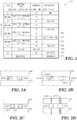
- FIG. 1il lustrates an example stack-up of the layers of an antenna structure 100 .
- Antenna structure 100may include a radiating-eiement layer 102 comprising a patterned conductive material, a ground layer 106 comprising conductive material disposed on a dielectric substrate 108, and a feed-line layer 110 comprising conductive material disposed on a dielectric substrate 1 12,
- the antenna structure 100may also include an air-gap layer 104 disposed between the radiating-eiement layer 102 and the ground layer 106.
- the air-gap layer 104may include a plurality of spacing elements to separate the radiating-eiement layer 102 and the ground layer 106 by a predetermined distance to provide a gap.
- the air-gap layer 104may comprise one or more cavities.
- the feed-line layer 110may be disposed adjacent to the ground layer 106 opposite the air-gap layer 104.
- the use of the air-gap layer 104 to separate the radiating-element layer 102 and the ground layer 106may help increase the impedance bandwidth of the antenna structure 100.
- the use of air-gap layer 104may also help minimize the permittivity ( ⁇ ⁇ ⁇ 0) which helps minimize the thickness of the antenna structure 100 (i.e., in the z-direction).
- ⁇ ⁇ ⁇ 0permittivity
- up to an 8 GBz impedance bandwidth at some millimeter-wave frequenciese.g., 57.4 GHz to 65.7GHz
- millimeter-wave frequenciese.g., 57.4 GHz to 65.7GHz
- air-gap layer 104is referred to as an 'air-gap' layer, the scope of it is not limited in this respect.
- the gapmay be filled with any substance (gas, liquid or solid) to help reduce or minimize the permittivity and increase the impedance bandwidth of the antenna structure 100.
- a dielectric constant of one or close to oneis desirable.
- Substances that may be suitable for use in the gapmay include air and other gases including inert gases, as well as non-conductive low permittivity materials.
- a vacuummay be provided in the gap.
- the separation between the radiatmg- eiement layer 102 and the ground layer 106may range from a little as 200um (microns) to as great as 6G0um or more depending on the operating frequency. In some embodiments, the separation between the radiating-element layer 102 and the ground layer 106 may be less than 0,08 wavelengths of a millimeter-wave operating frequency (e.g., about 400um at 60GHz). In some examples, the separation may be as great as 1 millimeter or more depending on the operating frequency.
- the ground layer 106may comprise conductive material disposed on a ground-layer dielectric substrate 108.
- the feed-line layer 110may comprise conductive material disposed on a feed-line dielectric substrate 1 12.
- the radiating-element layer 102, the ground layer 106, the feed-line layer 1 10, and the air-gap layer 104may be arranged to operate as an antenna for communication of millimeter-wave signals.
- the separation between the radiating-element layer 102 and the ground layer 106may be less than 0.08 wavelengths.
- the antenna structure 100may be used for communication at millimeter-wave frequencies within one or more of the WiGig channels.
- Millimeter- wave frequenciesmay include operating frequencies ranging from 30 GHz to up to 300 GHz.
- the patterned conductive material of the radiating-element layer 102may be disposed on a radiating-element dielectric substrate 101 opposite the air-gap layer 104.
- no substrateis provided at the location of the air-gap layer 104 and a suitable dielectric material may be used to position the conductive material of the radiating-element layer 102.
- the dielectric substrate 101may be a thin dielectric substrate (e.g., as thin as 60um if metal is provided on both sides of the substrate and as thin as 200um - 400um if metal is provided on one side of the substrate). In some examples illustrated in FIG.
- the radiating-element layer 102may be referred to as layer zero (L0), the ground layer 106 may be referred to as layer one (LI) and the feed-line layer 1 10 may be referred to as layer two (L2).
- the antenna structure 100may also include other layers including other dielectric substrates as illustrated in FIG. 1 .
- FIGs. 2A - Eillustrate side views of some of the layers of the antenna structure of FIG. 1 using different types of spacing elements.
- the spacing elements used to separate the radiating-element layer 102 and the ground layer 106 by a predetermined distancemay comprise solder balls 204 A.
- the solder balls 204 Amay be part of a ball-grid array (BGA).
- the solder balls 204Amay be provided to separate the radiating-element layer 102 and the ground layer 106 by a predetermined distance to provide a gap.
- the solder balls 204Amay also be used to help align the radiating-element layer 102 with the ground layer 106. This is described in more detail below.
- some further characterization of the antenna structure 100may be performed to adjust the height of the solder balls 204A after reflow to provide a predetermined distance between the radiating-element layer 102 with the ground layer 106.
- the spacing elementsmay also include spacers 204B (see FIG. 2B ).
- the spacers 204Bmay be used in addition to solder balls 204A.
- the spacers 204Bmay help control the gap during BGA reflow attach operations.
- the finished BGA heightmay be close to that of the spacers 204B to provide the predetermined distance between the radiating-element layer 102 and the ground layer 106.
- spacers 204B without solder balls 204Amay be used to separate the radiating-element layer 102 and the ground layer 106.
- the solder balls 204 Amay have a melting point temperature that is greater than the reflow temperature of the solder used to attach the solder balls 204 A to the boards (e.g., the radiating- element layer 102 with the ground layer 106). In these examples, the solder balls may hold their shape during reflow to help maintain the gap height (i.e., the predetermined distance between the radiating-element layer 102 with the ground layer 106).
- FIG. 2CAn example is illustrated in which solder 203 may be used to attach the solder balls 204D to the boards.
- the spacing elements to separate the radiating-element layer 102 and the ground layer 106may comprise connectors 204C (see FIGs. 2D and 2E ).
- the connectors 204Cmay be arranged to align the radiating-element layer 102 and the ground layer 106.
- the connectors 204Cmay be used with spacers 204E to separate the radiating- element layer 102 and the ground layer 106 by the predetermined distance to provide a gap.
- the use of connectors 204Cmay allow the radiating-element layer 102 and the ground layer 106 to self-align during assembly.
- the connectors 204Cmay extend through the boards (see FIG. 2D ), while in other examples, the connectors 204C may extend only part way through the boards (see FIG. 2E ).
- the connectors 204Cmay comprise pins.
- the pinsmay be stake pins although this is not a requirement.
- the pinsmay be soldered into a plated hole (not separately illustrated).
- the pinsmay be placed on a plated or non-plated thru-hole (i.e., not soldered) and the radiating-element layer 102 and the ground layer 106 maybe held together by other means (e.g., solder balls, adhesive, etc.).
- the connectors 204Cmay comprise a snap-fit or rivet-like device. In some examples, the connectors 204C may have a controlled standoff height to provide the predetermined distance to separate the radiating-element layer 102 and the ground layer 106.
- FIG. 3illustrates a side view of some of the layers of the antenna structure of FIG. 1 in which the radiating-element layer is printed on a non- conductive chassis 301.
- the patterned conductive material of the radiating-element layer 102may be printed on or disposed on a non-conductive chassis 301.
- the non- conductive chassis 301may be a docking station chassis or a chassis of any mobile platform and would serve as a dielectric substrate for the conductive material of the radiating-element layer 102, although it is not limited in this respect.
- FIG. 4Aillustrates a side view of some of the layers of an antenna structure 400 that includes a single cavity.
- FIG. 4Billustrates a top/bottom view of the cavity of the antenna structure 400 of FIG. 4A .
- FIG. 5Aillustrates a side view of some of the layers of an antenna structure 500 that includes a plurality of cavities in accordance with some embodiments.
- FIG. 5Billustrates a top/bottom view of the cavities of the antenna structure 500 of FIG. 5 A , in accordance with some embodiments.
- the antenna structures 400/500may comprise a radiating-element layer 402/502 comprising patterned conductive material disposed on a radiating- element dielectric substrate 404/504, a ground layer 406 comprising conductive material, and a feed- line layer 410 comprising conductive material.
- the radiating-element dielectric substrate 404may include one or more cavities 414/514 between the radiating-element layer 402 and the ground layer 406. Accordingly, a gap may be provided between the radiating-element layer 402/502 and the ground layer 406.
- the feed-line layer 410is disposed adjacent to the ground layer 406 opposite the radiating- element dielectric substrate 404.
- the one or more cavities 414/514 between the radiating-element layer 402/502 and the ground layer 406may help increase the impedance bandwidth of the antenna structure 400/500.
- the use of one or more cavities 414/514 within the radiating-element dielectric substrate 404/504may help minimize the permittivity which helps minimize the thickness of the antenna (in the z-direetion).
- the use of one or more cavities 414/514 in a non- conductive substrate 404/504may effectively provide a gap between the radiating-element layer 402 and the ground layer 406.
- the cavities 414/514may be filled with air or may be filled with almost any substance as discussed above to help minimize the permittivity.
- the ground layer 406may comprise conductive material disposed on a ground-layer dielectric substrate 408.
- the feed-line layer 410may comprise conductive material disposed on a feed-line dielectric substrate.
- the patterned conductive material of the radiating-element layer 402may comprise a single patch associated with the single cavity 414.
- the dielectric substrate 404may be arranged to provide a single larger cavity 414 between the radiating-element layer 402 and the ground layer 406.
- FIG. 4Billustrates a single large cavity 414
- the cavity 414may include structural elements, such as spacers.
- the patterned conductive material of the radiating-element layer 502( FIG. 5 A) comprises a plurality of patches as described above, each patch may be associated with one cavity 514.
- each cavitymay be associated with a single patch (e.g., metal for a patch would reside on top of or be provided over every cavity).
- the dielectric substrate 504may be arranged to provide a plurality of smaller cavities 514 between the radiating-element layer 502 and the ground layer 406.
- FIG. 5Billustrates a plurality of equal ly sized square-shaped cavities within the radiating-element dielectric substrate 504, this is not a requirement.
- the cavities 514may be have other sized and/or may be differently sized.
- the radiating-element layer 402/502( FIG. 4A or FIG. 5A ) also comprises a plurality of thru-holes.
- small holes in the radiating-element layer 402/502i.e., L0
- small holesare provided in the radiating-element layer 402/502 when the radiating-element dielectric substrate 404/504 comprises one or more cavities 414/514 (e.g., for release of hot air).
- FIG. 6illustrates three views of a radiating-element dielectric substrate 604 with thru-holes in accordance with some other embodiments.
- the radiating-element dielectric substrate 604has a plurality of thru-holes 614.
- the radiating-element dielectric substrate 604may be used in place of the dielectric substrate 404 ( FIGs, 4 A and 4B ) of antenna structure 400 or may be used in place of the dielectric substrate 504 ( FIGs. 5 A and 5B ) of antenna structure 500.
- the thru- holes 614may help increase the impedance bandwidth of an antenna structure and help minimize the permittivity. This may help minimize the thickness of an antenna structure.
- Reference number 604Aillustrates an end view of radiating- element dielectric substrate 604 (i.e., from the end or edge)
- reference number 604Bis a side view of radiating-element dielectric substrate 604 sectioned through the thru-holes 614
- reference number 604Cillustrates a top view of radiating-element dielectric substrate 604
- the radiating-element layer(e.g., radiating-element layer 402/502 ( FIG. 4A or FIG. 5A )) may also include a plurality of thru-holes.
- FIG. 7 Aillustrates patterned conductive material of the radiating- element layer.
- FIG. 7Billustrates conductive material of the ground layer 106 in accordance with some examples of FIG, 7A .
- the patterned conductive material of the radiating-element layermay comprise a plurality of patches 702 ( FIG. 7A ) and the conductive material of the ground layer 106 may comprise a plurality of slots 704 ( FIG. 7B ).
- Each slot 704may be devoid of conductive material may be aligned with one of the patches 702 to provide a patch/slot set.
- the feed-line layer 1 10/410FIG. 1 or FIG. 4A/FIG. 5 A
- each patch/ slot setmay have a single feed line.
- the slots 704may operate as apertures allowing the feed lines to couple signals to and from the patches 702.
- the feed lines of the feed-line layer 110/410may comprise microstrip feed lines to provide an aperture-coupled microstrip antenna configuration.
- the phase excitation of each element or patch 702may be controlled to provide an aperture-coupled microstrip phased-array antenna configuration.
- a microstrip feed linemay couple to a patch 702 through an aperture (e.g., slot 704) in the ground plane (i.e., ground layer 106 of FIG. 1 or ground layer 406 FIGs. 4A and 5A ).
- each patch 702by itself may operate as a single antenna or a single element of an array antenna.
- the patches 702may be square, circular, or rectangular or may have another shape based on desired antenna characteristics. In some examples, rather than patches 702, other conductive material patterns may be used. Slots 704 may be square, circular or bowtie-shaped, or may have another shape based on the desired antenna characteristics. In some examples, the conductive material of the radiating-element layer and the slots may be arranged to provide a single feed circularly polarized phased array antenna. A broadband antenna may also be provided.
- the antenna structures described hereinmay be arranged to provide one or more directional or omnidirectional antennas, including, for example, dipole antennas, monopole antennas, patch antennas, loop antennas, microstrip antennas or other types of antennas suitable for transmission of RF or millimeter-wave signals.
- each aperturemay be considered a separate antenna.
- the antenna structuremay be configured to take advantage of spatial diversity and the different channel characteristics in a MIMO channel.
- the patterned conductive material of the radiating-element layermay include a plurality of solder-ball pads 706 that are electrically isolated from the patches 702. Each of the pads 706 may be used for attachment of one of the solder balls 204 A. to the radiating-element dielectric layer (either layer 101 ( FIG. 1 ) or the non-conductive chassis 301 ( FIG. 3 ).
- the solder balls 204Afunctioning as spacing elements, may provide a mechanical connection (but not an electrical connection) between the ground layer 106 and the radiating-element layer ( FIG. 7A ).
- the spacing elementsmay be evenly distributed to provide vertical alignment between the slots 704 and the patches 702 such that- each slot 704 is centered below a corresponding patch 702.
- Other alignment techniques previously describedmay also be suitable for the alignment of these layers.
- a wireless communication devicemay be provided.
- the wireless communication devicemay be, for example, a mobile device or a docking station, although the scope of these embodiments is not limited in this respect.
- the wireless communication devicemay include a millimeter-wave transceiver and an antenna structure coupled to the millimeter-wave transceiver.
- the antennamay be arranged for communicating the millimeter-wave signals with another device. Any of the embodiments of the antenna structures described above may be suitable for use in the wireless communication device.
- the millimeter-wave transceivermay be part of a WiGig module, although this is not a requirement.
- the wireless communication devicemay be personal digital assistant (PDA), a laptop or portable computer with wireless communication capability, a web tablet, a wireless telephone, a smartphone, a wireless headset, a pager, an instant messaging device, a digital camera, an access point, a television, a medical device (e.g., a heart rate monitor, a blood pressure monitor, etc.), or other device that may receive and/or transmit information wirelessly.
- the wireless communication devicemay include one or more of a keyboard, a display, a non- volatile memory port, multiple antennas, a graphics processor, an application processor, speakers, and other mobile device elements.
- the displaymay be a liquid-crystal display (LCD) screen including a touch screen.
- LCDliquid-crystal display
- the antenna structurewhen the wireless communication device is a docking station, the antenna structure may be configured as an aperture- coupled antenna for communicating circularly-polarized signals with a mobile device that communicates signals having one of vertical, horizontal or slanted polarizations.
- the antenna structure of the docking stationsince the antenna structure of the docking station may be arranged to communicate circularly-polarized signals, the docking station may be able to communicate with mobile devices that communicate signals of various pol arizations.
- the antenna of the docking stationmay be a highly-directional phased-array antenna.
- the antenna structuremay provide an antenna for communicating signals having one of vertical, horizontal or slanted polarizations, although this is not a requirement.
- the mobile devi cemay be arranged to communicate with the docking station in accordance with a WiGig protocol.
Landscapes
- Engineering & Computer Science (AREA)
- Computer Networks & Wireless Communication (AREA)
- Details Of Aerials (AREA)
- Waveguide Aerials (AREA)
Description
- Embodiments pertain to antennas and antenna structures. Some embodiments pertain to antennas and antenna structures for millimeter-wave communications. Some embodiments pertain to wireless communication devices (e.g., mobile devices and docking stations) that use antennas and antenna structures for communication of wireless signals. Some embodiments relate to devices that operate in accordance with the Wireless Gigabit Alliance (WiGig) (e.g., IEEE 802.1 lad) protocol.
- Antenna size and antenna performance are some of the more challenging issues with wireless communications, particularly wireless communications at millimeter-wave wavelengths. High-speed wireless data communication protocols such as the WiGig protocol utilize a very broad bandwidth (e.g., up to 8GHz). This poses a challenge on antenna designers who are already managing to meet other requirements such as compact form factor, high directivity, adaptive beam steering, low cost, etc. Some of these requirements make it difficult for an antenna to achieve a broad impedance bandwidth (i.e., the insertion loss bandwidth). For planar antennas printed on a thin dielectric substrate (h « wavelength) of an arbitrary shape, the bandwidth may be directly proportional to the thickness of the substrate (h) and inversely proportional to the dielectric constant (εΓ). A thicker substrate, however, may result in an increase in overall antenna volume and may also mean more complicated and costly fabrication. This makes achieving a broad impedance bandwidth, while at the same time meeting other antenna performance, size and manufacturing goals, a significant challenge.
- Thus there are general needs for antennas and antenna structures that can achieve a broad impedance bandwidth while meeting other performance, size and manufacturing goals. There are also general needs for millimeter- wave antenna structures that can achieve a broad impedance bandwidth and may be suitable for communications in accordance with the WiGig protocol. There are also general needs for wireless communication devices that can communicate with improved performance at millimeter-wave frequencies.
GB2484704 A US2007/296634 A1 teaches an aperture-coupled antenna which has a first radiation electrode, a ground area and a wave guide which is implemented to supply energy to the antenna. The wave guide is arranged spaced apart from the ground area on a first side of the ground area, and the first radiation electrode is arranged spaced apart from the ground area on a second side of the ground area. The ground area has an aperture including a first slot in the ground area, a second slot in the ground area and a third slot in the ground area. The first slot and the second slot together form a slot in the shape of a cross. The third slot passes through an intersection of the first slot and the second slot. The wave guide and the radiation electrode are arranged such that energy can be coupled from the wave guide through the aperture to the patch.EP2144329 A1 teaches a radio-frequency integrated circuit chip package with N integrated aperture-coupled patch antennas, N being at least one, which includes a cover portion with N generally planar patches, and a main portion coupled to the cover portion. The main portion in turn comprises at least one generally planar ground plane spaced inwardly from the N generally planar patches and substantially parallel thereto. The ground plane is formed with at least N coupling aperture slots therein. The slots are substantially opposed to the patches. The main portion also includes N feed lines spaced inwardly from the N generally planar patches and substantially parallel thereto, and at least one radio frequency chip coupled to the feed lines and the ground plane. The cover portion and the main portion cooperatively define an antenna cavity, with the N generally planar patches located in the antenna cavity.US 2010/327068 A1 discloses an antenna structure comprising a radiating-element layer comprising patterned conductive material disposed on a radiating-element dielectric substrate, the patterned conductive material comprising a patch antenna, a ground layer comprising conductive material, and a feed-line layer comprising conductive material, wherein the radiating-element dielectric substrate comprises a thru-hole between the radiating-element layer and the ground layer, and wherein the radiating-element layer further comprises a thru-hole connected to the thru-hole of the radiating-element dielectric substrate, wherein the feed-line layer is disposed adjacent to the ground layer opposite the radiating element dielectric substrate.US 2012/280380 A1 discloses an antenna structure comprising a radiating-element layer, comprising patterned conductive material disposed on a radiating-element dielectric substrate, the patterned conductive material comprising a plurality of patch antennas, a ground layer comprising conductive material, and a feed-line layer comprising conductive material, wherein the radiating-element dielectric substrate comprises a plurality of thru-holes between the radiating-element layer and the ground layer, wherein the feed-line layer is disposed at adjacent to the ground layer opposite the radiating-element dielectric substrate.
The present invention provides an antenna structure according to the single claim.FIG. 1 illustrates an example stack-up of the layers of an antenna structure in accordance with some embodiments;FIGs. 2A - E illustrate side views of some of the layers of the antenna structure ofFIG. 1 in accordance with some embodiments;FIG. 3 illustrates a side view of some of the layers of the antenna structure ofFIG. 1 in which the radiating-element layer is printed on a non- conductive chassis in accordance with some embodiments;FIG. 4A illustrates a side view of some of the layers of an antenna structure that includes a single cavity;FIG. 4B illustrates a top/bottom view of the cavity of the antenna structure ofFIG. 4A ;FIG. 5A illustrates a side view of some of the layers of an antenna structure that includes a plurality of cavities in accordance with some embodiments;FIG. 5B illustrates a top/bottom view of the cavities of the antenna structure ofFIG. 5 A in accordance with some embodiments;FIG. 6 illustrates three views of a radiating-element dielectric substrate with thru-holes in accordance with some embodiments;FIG. 7A illustrates patterned conductive material of the radiating- element layer in accordance with some embodiments; andFIG. 7B illustrates conductive material of the ground layer in accordance with some embodiments.- The following description and the drawings sufficiently illustrate specific embodiments to enable those skilled in the art. to practice them. Other embodiments may incorporate structural, logical, electrical, process, and other changes. Portions and features of some embodiments may be included in, or substituted for, those of other embodiments.
FIG. 1 il lustrates an example stack-up of the layers of anantenna structure 100 .Antenna structure 100 may include a radiating-eiement layer 102 comprising a patterned conductive material, aground layer 106 comprising conductive material disposed on adielectric substrate 108, and a feed-line layer 110 comprising conductive material disposed on adielectric substrate 1 12, Theantenna structure 100 may also include an air-gap layer 104 disposed between the radiating-eiement layer 102 and theground layer 106. In these examples, the air-gap layer 104 may include a plurality of spacing elements to separate the radiating-eiement layer 102 and theground layer 106 by a predetermined distance to provide a gap. In some embodiments described in more detail below, the air-gap layer 104 may comprise one or more cavities. As il lustrated, the feed-line layer 110 may be disposed adjacent to theground layer 106 opposite the air-gap layer 104.- The use of the air-
gap layer 104 to separate the radiating-element layer 102 and theground layer 106 may help increase the impedance bandwidth of theantenna structure 100. The use of air-gap layer 104 may also help minimize the permittivity (εΓ∗ε0) which helps minimize the thickness of the antenna structure 100 (i.e., in the z-direction). In some examples , up to an 8 GBz impedance bandwidth at some millimeter-wave frequencies (e.g., 57.4 GHz to 65.7GHz) may be achieved, although the scope of the embodiments is not limited in this respect. - Although air-
gap layer 104 is referred to as an 'air-gap' layer, the scope of it is not limited in this respect. In some examples, the gap may be filled with any substance (gas, liquid or solid) to help reduce or minimize the permittivity and increase the impedance bandwidth of theantenna structure 100. In these examples, a dielectric constant of one or close to one is desirable. Substances that may be suitable for use in the gap may include air and other gases including inert gases, as well as non-conductive low permittivity materials. In some examples, a vacuum may be provided in the gap. - In some examples, the separation between the radiatmg-
eiement layer 102 and theground layer 106 may range from a little as 200um (microns) to as great as 6G0um or more depending on the operating frequency. In some embodiments, the separation between the radiating-element layer 102 and theground layer 106 may be less than 0,08 wavelengths of a millimeter-wave operating frequency (e.g., about 400um at 60GHz). In some examples, the separation may be as great as 1 millimeter or more depending on the operating frequency. - In some examples, the
ground layer 106 may comprise conductive material disposed on a ground-layer dielectric substrate 108. The feed-line layer 110 may comprise conductive material disposed on a feed-line dielectric substrate 1 12. - In some WiGig examples, the radiating-
element layer 102, theground layer 106, the feed-line layer 1 10, and the air-gap layer 104 (as well as other layers) may be arranged to operate as an antenna for communication of millimeter-wave signals. The separation between the radiating-element layer 102 and theground layer 106 may be less than 0.08 wavelengths. In these examples, theantenna structure 100 may be used for communication at millimeter-wave frequencies within one or more of the WiGig channels. - Millimeter- wave frequencies may include operating frequencies ranging from 30 GHz to up to 300 GHz.
- In some examples, the patterned conductive material of the radiating-
element layer 102 may be disposed on a radiating-element dielectric substrate 101 opposite the air-gap layer 104. In these examples, no substrate is provided at the location of the air-gap layer 104 and a suitable dielectric material may be used to position the conductive material of the radiating-element layer 102. Thedielectric substrate 101 may be a thin dielectric substrate (e.g., as thin as 60um if metal is provided on both sides of the substrate and as thin as 200um - 400um if metal is provided on one side of the substrate). In some examples illustrated inFIG. 1 , the radiating-element layer 102 may be referred to as layer zero (L0), theground layer 106 may be referred to as layer one (LI) and the feed-line layer 1 10 may be referred to as layer two (L2). Theantenna structure 100 may also include other layers including other dielectric substrates as illustrated inFIG. 1 . FIGs. 2A - E illustrate side views of some of the layers of the antenna structure ofFIG. 1 using different types of spacing elements. As illustrated inFIG. 2A , the spacing elements used to separate the radiating-element layer 102 and theground layer 106 by a predetermined distance may comprisesolder balls 204 A. In some of these embodiments, thesolder balls 204 A may be part of a ball-grid array (BGA). Thesolder balls 204A may be provided to separate the radiating-element layer 102 and theground layer 106 by a predetermined distance to provide a gap. Thesolder balls 204A may also be used to help align the radiating-element layer 102 with theground layer 106. This is described in more detail below. In some examples, some further characterization of theantenna structure 100 may be performed to adjust the height of thesolder balls 204A after reflow to provide a predetermined distance between the radiating-element layer 102 with theground layer 106.- In some examples, the spacing elements may also include spacers 204B (see
FIG. 2B ). In these examples, the spacers 204B may be used in addition tosolder balls 204A. In these BGA examples, the spacers 204B may help control the gap during BGA reflow attach operations. In these examples, the finished BGA height may be close to that of the spacers 204B to provide the predetermined distance between the radiating-element layer 102 and theground layer 106. In some alternate examples, spacers 204B withoutsolder balls 204A may be used to separate the radiating-element layer 102 and theground layer 106. - In some of these examples, the
solder balls 204 A may have a melting point temperature that is greater than the reflow temperature of the solder used to attach thesolder balls 204 A to the boards (e.g., the radiating-element layer 102 with the ground layer 106). In these examples, the solder balls may hold their shape during reflow to help maintain the gap height (i.e., the predetermined distance between the radiating-element layer 102 with the ground layer 106). An example is illustrated inFIG. 2C in which solder 203 may be used to attach the solder balls 204D to the boards. - In some other example, the spacing elements to separate the radiating-
element layer 102 and theground layer 106 may comprise connectors 204C (seeFIGs. 2D and2E ). The connectors 204C may be arranged to align the radiating-element layer 102 and theground layer 106. In these examples, the connectors 204C may be used withspacers 204E to separate the radiating-element layer 102 and theground layer 106 by the predetermined distance to provide a gap. The use of connectors 204C may allow the radiating-element layer 102 and theground layer 106 to self-align during assembly. - In some examples, the connectors 204C may extend through the boards (see
FIG. 2D ), while in other examples, the connectors 204C may extend only part way through the boards (seeFIG. 2E ). In some examples, the connectors 204C may comprise pins. The pins may be stake pins although this is not a requirement. In some alternate examples, the pins may be soldered into a plated hole (not separately illustrated). In some other examples, the pins may be placed on a plated or non-plated thru-hole (i.e., not soldered) and the radiating-element layer 102 and theground layer 106 maybe held together by other means (e.g., solder balls, adhesive, etc.). - In some examples, the connectors 204C may comprise a snap-fit or rivet-like device. In some examples, the connectors 204C may have a controlled standoff height to provide the predetermined distance to separate the radiating-
element layer 102 and theground layer 106. FIG. 3 illustrates a side view of some of the layers of the antenna structure ofFIG. 1 in which the radiating-element layer is printed on a non-conductive chassis 301. In these examples, the patterned conductive material of the radiating-element layer 102 may be printed on or disposed on anon-conductive chassis 301. The non-conductive chassis 301 may be a docking station chassis or a chassis of any mobile platform and would serve as a dielectric substrate for the conductive material of the radiating-element layer 102, although it is not limited in this respect.FIG. 4A illustrates a side view of some of the layers of anantenna structure 400 that includes a single cavity.FIG. 4B illustrates a top/bottom view of the cavity of theantenna structure 400 ofFIG. 4A .FIG. 5A illustrates a side view of some of the layers of anantenna structure 500 that includes a plurality of cavities in accordance with some embodiments.FIG. 5B illustrates a top/bottom view of the cavities of theantenna structure 500 ofFIG. 5 A , in accordance with some embodiments.- In the i examples illustrated in
FIGs. 4A and 4B and the embodiments illustrated inFIGs. 5 A. and 5B , theantenna structures 400/500 may comprise a radiating-element layer 402/502 comprising patterned conductive material disposed on a radiating-element dielectric substrate 404/504, aground layer 406 comprising conductive material, and a feed-line layer 410 comprising conductive material. The radiating-element dielectric substrate 404 may include one ormore cavities 414/514 between the radiating-element layer 402 and theground layer 406. Accordingly, a gap may be provided between the radiating-element layer 402/502 and theground layer 406. In these embodiments, the feed-line layer 410 is disposed adjacent to theground layer 406 opposite the radiating-element dielectric substrate 404. - The one or
more cavities 414/514 between the radiating-element layer 402/502 and theground layer 406 may help increase the impedance bandwidth of theantenna structure 400/500. The use of one ormore cavities 414/514 within the radiating-element dielectric substrate 404/504 may help minimize the permittivity which helps minimize the thickness of the antenna (in the z-direetion). The use of one ormore cavities 414/514 in a non-conductive substrate 404/504 may effectively provide a gap between the radiating-element layer 402 and theground layer 406. Thecavities 414/514 may be filled with air or may be filled with almost any substance as discussed above to help minimize the permittivity. - The
ground layer 406 may comprise conductive material disposed on a ground-layer dielectric substrate 408. The feed-line layer 410 may comprise conductive material disposed on a feed-line dielectric substrate. - In single-cavity examples, the patterned conductive material of the radiating-element layer 402 (
FIG. 4A ) may comprise a single patch associated with thesingle cavity 414. In some single-cavity examples, the dielectric substrate 404 (seeFIG. 4B ) may be arranged to provide a singlelarger cavity 414 between the radiating-element layer 402 and theground layer 406. AlthoughFIG. 4B illustrates a singlelarge cavity 414, thecavity 414 may include structural elements, such as spacers. - In multi-cavity embodiments, the patterned conductive material of the radiating-element layer 502 (
FIG. 5 A) comprises a plurality of patches as described above, each patch may be associated with onecavity 514. In these multi-cavity embodiments, each cavity may be associated with a single patch (e.g., metal for a patch would reside on top of or be provided over every cavity). - In some multi-cavity embodiments, the dielectric substrate 504 (see
FIG. 5B ) may be arranged to provide a plurality ofsmaller cavities 514 between the radiating-element layer 502 and theground layer 406. AlthoughFIG. 5B illustrates a plurality of equal ly sized square-shaped cavities within the radiating-element dielectric substrate 504, this is not a requirement. In some embodiments, thecavities 514 may be have other sized and/or may be differently sized. - In some embodiments, the radiating-
element layer 402/502 (FIG. 4A or FIG. 5A ) also comprises a plurality of thru-holes. In these embodiments, small holes in the radiating-element layer 402/502 (i.e., L0) may allow any hot air that may be trapped during manufacturing to be released. In some embodiments, small holes are provided in the radiating-element layer 402/502 when the radiating-element dielectric substrate 404/504 comprises one ormore cavities 414/514 (e.g., for release of hot air). FIG. 6 illustrates three views of a radiating-element dielectric substrate 604 with thru-holes in accordance with some other embodiments. In these embodiments, the radiating-element dielectric substrate 604 has a plurality of thru-holes 614. In these embodiments, the radiating-element dielectric substrate 604 may be used in place of the dielectric substrate 404 (FIGs, 4 A and 4B ) ofantenna structure 400 or may be used in place of the dielectric substrate 504 (FIGs. 5 A and 5B ) ofantenna structure 500. The thru-holes 614 may help increase the impedance bandwidth of an antenna structure and help minimize the permittivity. This may help minimize the thickness of an antenna structure.Reference number 604A illustrates an end view of radiating- element dielectric substrate 604 (i.e., from the end or edge), reference number 604B is a side view of radiating-element dielectric substrate 604 sectioned through the thru-holes 614, and reference number 604C illustrates a top view of radiating-element dielectric substrate 604,- In some embodiments in which the radiating-
element dielectric substrate 604 includes thru-holes 614, the radiating-element layer (e.g., radiating-element layer 402/502 (FIG. 4A or FIG. 5A )) may also include a plurality of thru-holes. FIG. 7 A illustrates patterned conductive material of the radiating- element layer.FIG. 7B illustrates conductive material of theground layer 106 in accordance with some examples ofFIG, 7A . In these examples, the patterned conductive material of the radiating-element layer may comprise a plurality of patches 702 (FIG. 7A ) and the conductive material of theground layer 106 may comprise a plurality of slots 704 (FIG. 7B ). Eachslot 704 may be devoid of conductive material may be aligned with one of thepatches 702 to provide a patch/slot set. In these examples, the feed-line layer 1 10/410 (FIG. 1 orFIG. 4A/FIG. 5 A) may comprise one or more feed lines to couple with the plurality ofpatches 702 through one or more of theslots 704 in theground layer 106 to provide an aperture-coupled antenna configuration.- In some examples, each patch/ slot set may have a single feed line. In these examples, the
slots 704 may operate as apertures allowing the feed lines to couple signals to and from thepatches 702. In some of these examples, the feed lines of the feed-line layer 110/410 may comprise microstrip feed lines to provide an aperture-coupled microstrip antenna configuration. In some phased-array examples, the phase excitation of each element or patch 702 may be controlled to provide an aperture-coupled microstrip phased-array antenna configuration. In these examples, a microstrip feed line may couple to apatch 702 through an aperture (e.g., slot 704) in the ground plane (i.e.,ground layer 106 ofFIG. 1 orground layer 406FIGs. 4A and 5A ). In some of these examples, eachpatch 702 by itself may operate as a single antenna or a single element of an array antenna. - In examples, the
patches 702 may be square, circular, or rectangular or may have another shape based on desired antenna characteristics. In some examples, rather thanpatches 702, other conductive material patterns may be used.Slots 704 may be square, circular or bowtie-shaped, or may have another shape based on the desired antenna characteristics. In some examples, the conductive material of the radiating-element layer and the slots may be arranged to provide a single feed circularly polarized phased array antenna. A broadband antenna may also be provided. - In some embodiments, the antenna structures described herein may be arranged to provide one or more directional or omnidirectional antennas, including, for example, dipole antennas, monopole antennas, patch antennas, loop antennas, microstrip antennas or other types of antennas suitable for transmission of RF or millimeter-wave signals. In some aperture-coupled embodiments, each aperture may be considered a separate antenna. In some multiple-input multiple-output (MIMO) embodiments, the antenna structure may be configured to take advantage of spatial diversity and the different channel characteristics in a MIMO channel.
- In some examples, when
solder balls 204A are used as the spacing elements, the patterned conductive material of the radiating-element layer may include a plurality of solder-ball pads 706 that are electrically isolated from thepatches 702. Each of the pads 706 may be used for attachment of one of thesolder balls 204 A. to the radiating-element dielectric layer (either layer 101 (FIG. 1 ) or the non-conductive chassis 301 (FIG. 3 ). - In some examples, the
solder balls 204A, functioning as spacing elements, may provide a mechanical connection (but not an electrical connection) between theground layer 106 and the radiating-element layer (FIG. 7A ). In these examples, the spacing elements may be evenly distributed to provide vertical alignment between theslots 704 and thepatches 702 such that- eachslot 704 is centered below acorresponding patch 702. Other alignment techniques previously described may also be suitable for the alignment of these layers. - In some embodiments, a wireless communication device may be provided. The wireless communication device may be, for example, a mobile device or a docking station, although the scope of these embodiments is not limited in this respect. In these embodiments, the wireless communication device may include a millimeter-wave transceiver and an antenna structure coupled to the millimeter-wave transceiver. The antenna may be arranged for communicating the millimeter-wave signals with another device. Any of the embodiments of the antenna structures described above may be suitable for use in the wireless communication device. In some embodiments, the millimeter-wave transceiver may be part of a WiGig module, although this is not a requirement.
- In some embodiments, the wireless communication device may be personal digital assistant (PDA), a laptop or portable computer with wireless communication capability, a web tablet, a wireless telephone, a smartphone, a wireless headset, a pager, an instant messaging device, a digital camera, an access point, a television, a medical device (e.g., a heart rate monitor, a blood pressure monitor, etc.), or other device that may receive and/or transmit information wirelessly. In some embodiments, the wireless communication device may include one or more of a keyboard, a display, a non- volatile memory port, multiple antennas, a graphics processor, an application processor, speakers, and other mobile device elements. The display may be a liquid-crystal display (LCD) screen including a touch screen.
- In these embodiments, when the wireless communication device is a docking station, the antenna structure may be configured as an aperture- coupled antenna for communicating circularly-polarized signals with a mobile device that communicates signals having one of vertical, horizontal or slanted polarizations. In these embodiments, since the antenna structure of the docking station may be arranged to communicate circularly-polarized signals, the docking station may be able to communicate with mobile devices that communicate signals of various pol arizations. In some of these embodiments, the antenna of the docking station may be a highly-directional phased-array antenna.
- In some embodiments in which the wireless communication device is a mobile device (e.g., a smart phone or other portable device), the antenna structure may provide an antenna for communicating signals having one of vertical, horizontal or slanted polarizations, although this is not a requirement. In some of these embodiments, the mobile devi ce may be arranged to communicate with the docking station in accordance with a WiGig protocol.
Claims (1)
- An antenna structure (400, 500) comprising:a radiating element dielectric substrate (604) anda radiating-element layer (402, 502) comprising patterned conductive material, wherein the patterned conductive material is disposed on the radiating-element dielectric substrate (604), the patterned conductive material comprising a plurality of patch antennas;a ground layer (406) comprising conductive material; anda feed-line layer (410) comprising conductive material, wherein the feed-line layer (410) is disposed adjacent the ground layer (406) opposite the radiating-element dielectric substrate (604),wherein the radiating-element dielectric substrate (604) comprises a plurality of thru-holes (614) between the radiating-element layer (402, 502) and the ground layer (406) andcharacterized in that the radiating-element layer (402; 502) further comprises a plurality of thru-holes connected to the thru-holes (614) of the radiating-element dielectric substrate ((604).
Applications Claiming Priority (1)
| Application Number | Priority Date | Filing Date | Title |
|---|---|---|---|
| PCT/US2013/055392WO2015023299A1 (en) | 2013-08-16 | 2013-08-16 | Millimeter wave antenna structures with air-gap layer or cavity |
Publications (3)
| Publication Number | Publication Date |
|---|---|
| EP3033804A1 EP3033804A1 (en) | 2016-06-22 |
| EP3033804A4 EP3033804A4 (en) | 2017-03-08 |
| EP3033804B1true EP3033804B1 (en) | 2020-12-02 |
Family
ID=52468558
Family Applications (1)
| Application Number | Title | Priority Date | Filing Date |
|---|---|---|---|
| EP13891615.0AActiveEP3033804B1 (en) | 2013-08-16 | 2013-08-16 | Millimeter wave antenna structures with air-gap layer or cavity |
Country Status (4)
| Country | Link |
|---|---|
| US (1) | US20150194724A1 (en) |
| EP (1) | EP3033804B1 (en) |
| CN (1) | CN105379007A (en) |
| WO (1) | WO2015023299A1 (en) |
Families Citing this family (12)
| Publication number | Priority date | Publication date | Assignee | Title |
|---|---|---|---|---|
| US10411505B2 (en)* | 2014-12-29 | 2019-09-10 | Ricoh Co., Ltd. | Reconfigurable reconstructive antenna array |
| US10361476B2 (en)* | 2015-05-26 | 2019-07-23 | Qualcomm Incorporated | Antenna structures for wireless communications |
| WO2017058446A1 (en)* | 2015-10-01 | 2017-04-06 | Intel Corporation | Integration of millimeter wave antennas in reduced form factor platforms |
| US20170110787A1 (en) | 2015-10-14 | 2017-04-20 | Apple Inc. | Electronic Devices With Millimeter Wave Antennas And Metal Housings |
| US9997844B2 (en) | 2016-08-15 | 2018-06-12 | Microsoft Technology Licensing, Llc | Contactless millimeter wave coupler, an electronic apparatus and a connector cable |
| CN113346221B (en)* | 2017-03-30 | 2024-03-19 | 住友电气工业株式会社 | Wireless module |
| EP3429026B1 (en)* | 2017-07-10 | 2020-12-02 | Nxp B.V. | An integrated circuit package and method of making thereof |
| CN107946738B (en)* | 2017-10-13 | 2020-11-17 | 瑞声科技(新加坡)有限公司 | Antenna system and mobile terminal |
| CN109888508B (en)* | 2018-12-28 | 2021-09-24 | 瑞声精密电子沭阳有限公司 | Phased array antenna |
| KR102647883B1 (en)* | 2019-01-25 | 2024-03-15 | 삼성전자주식회사 | Electronic device comprising antenna module |
| CN110212300B (en)* | 2019-05-22 | 2021-05-11 | 维沃移动通信有限公司 | Antenna unit and terminal equipment |
| KR20220131116A (en)* | 2021-03-19 | 2022-09-27 | 삼성전자주식회사 | Antenna structure and electronic device including same |
Citations (2)
| Publication number | Priority date | Publication date | Assignee | Title |
|---|---|---|---|---|
| US20100327068A1 (en)* | 2009-06-30 | 2010-12-30 | International Business Machines Corporation | Compact millimeter wave packages with integrated antennas |
| US20120280380A1 (en)* | 2011-05-05 | 2012-11-08 | Telesphor Kamgaing | High performance glass-based 60 ghz / mm-wave phased array antennas and methods of making same |
Family Cites Families (24)
| Publication number | Priority date | Publication date | Assignee | Title |
|---|---|---|---|---|
| US4170013A (en)* | 1978-07-28 | 1979-10-02 | The United States Of America As Represented By The Secretary Of The Navy | Stripline patch antenna |
| US4719470A (en)* | 1985-05-13 | 1988-01-12 | Ball Corporation | Broadband printed circuit antenna with direct feed |
| US4847625A (en)* | 1988-02-16 | 1989-07-11 | Ford Aerospace Corporation | Wideband, aperture-coupled microstrip antenna |
| US4903033A (en)* | 1988-04-01 | 1990-02-20 | Ford Aerospace Corporation | Planar dual polarization antenna |
| US4843400A (en)* | 1988-08-09 | 1989-06-27 | Ford Aerospace Corporation | Aperture coupled circular polarization antenna |
| US5043738A (en)* | 1990-03-15 | 1991-08-27 | Hughes Aircraft Company | Plural frequency patch antenna assembly |
| US5231406A (en)* | 1991-04-05 | 1993-07-27 | Ball Corporation | Broadband circular polarization satellite antenna |
| US5444453A (en)* | 1993-02-02 | 1995-08-22 | Ball Corporation | Microstrip antenna structure having an air gap and method of constructing same |
| FR2706085B1 (en)* | 1993-06-03 | 1995-07-07 | Alcatel Espace | Multilayer radiating structure with variable directivity. |
| JP4928052B2 (en)* | 2000-08-16 | 2012-05-09 | ヴァレオ・レイダー・システムズ・インコーポレーテッド | Switched beam antenna architecture |
| US6462711B1 (en)* | 2001-04-02 | 2002-10-08 | Comsat Corporation | Multi-layer flat plate antenna with low-cost material and high-conductivity additive processing |
| US6492947B2 (en)* | 2001-05-01 | 2002-12-10 | Raytheon Company | Stripline fed aperture coupled microstrip antenna |
| JP4121860B2 (en)* | 2001-05-17 | 2008-07-23 | サイプレス セミコンダクター コーポレーション | Ball grid array antenna |
| NL1019022C2 (en)* | 2001-09-24 | 2003-03-25 | Thales Nederland Bv | Printed antenna powered by a patch. |
| US6552687B1 (en)* | 2002-01-17 | 2003-04-22 | Harris Corporation | Enhanced bandwidth single layer current sheet antenna |
| GB2387036B (en)* | 2002-03-26 | 2005-03-02 | Ngk Spark Plug Co | Dielectric antenna |
| US7461444B2 (en)* | 2004-03-29 | 2008-12-09 | Deaett Michael A | Method for constructing antennas from textile fabrics and components |
| JP2006033583A (en)* | 2004-07-20 | 2006-02-02 | Sumitomo Electric Ind Ltd | antenna |
| DE102005010895B4 (en)* | 2005-03-09 | 2007-02-08 | Fraunhofer-Gesellschaft zur Förderung der angewandten Forschung e.V. | Aperture-coupled antenna |
| US7728774B2 (en)* | 2008-07-07 | 2010-06-01 | International Business Machines Corporation | Radio frequency (RF) integrated circuit (IC) packages having characteristics suitable for mass production |
| KR100988909B1 (en)* | 2008-09-23 | 2010-10-20 | 한국전자통신연구원 | Microstrip Patch Antenna with High Gain and Wideband Characteristics |
| US8278749B2 (en)* | 2009-01-30 | 2012-10-02 | Infineon Technologies Ag | Integrated antennas in wafer level package |
| US20100194643A1 (en)* | 2009-02-03 | 2010-08-05 | Think Wireless, Inc. | Wideband patch antenna with helix or three dimensional feed |
| GB2484704A (en)* | 2010-10-21 | 2012-04-25 | Bluwireless Tech Ltd | Patch antenna structure formed with an air gap in a flip-chip assembly |
- 2013
- 2013-08-16EPEP13891615.0Apatent/EP3033804B1/enactiveActive
- 2013-08-16CNCN201380078196.XApatent/CN105379007A/enactivePending
- 2013-08-16USUS14/124,207patent/US20150194724A1/ennot_activeAbandoned
- 2013-08-16WOPCT/US2013/055392patent/WO2015023299A1/enactiveApplication Filing
Patent Citations (2)
| Publication number | Priority date | Publication date | Assignee | Title |
|---|---|---|---|---|
| US20100327068A1 (en)* | 2009-06-30 | 2010-12-30 | International Business Machines Corporation | Compact millimeter wave packages with integrated antennas |
| US20120280380A1 (en)* | 2011-05-05 | 2012-11-08 | Telesphor Kamgaing | High performance glass-based 60 ghz / mm-wave phased array antennas and methods of making same |
Also Published As
| Publication number | Publication date |
|---|---|
| EP3033804A4 (en) | 2017-03-08 |
| US20150194724A1 (en) | 2015-07-09 |
| EP3033804A1 (en) | 2016-06-22 |
| CN105379007A (en) | 2016-03-02 |
| WO2015023299A1 (en) | 2015-02-19 |
Similar Documents
| Publication | Publication Date | Title |
|---|---|---|
| EP3033804B1 (en) | Millimeter wave antenna structures with air-gap layer or cavity | |
| US11677160B2 (en) | Electronic device having dual-band antennas mounted against a dielectric layer | |
| US11811133B2 (en) | Electronic device antenna arrays mounted against a dielectric layer | |
| US10978797B2 (en) | Electronic devices having antenna array apertures mounted against a dielectric layer | |
| US10608344B2 (en) | Electronic device antenna arrays mounted against a dielectric layer | |
| CN110534924B (en) | Antenna module and electronic equipment | |
| US9742070B2 (en) | Open end antenna, antenna array, and related system and method | |
| US11700035B2 (en) | Dielectric resonator antenna modules | |
| US11916311B2 (en) | Electronic devices having folded antenna modules | |
| CN110854529B (en) | A compact low-coupling tri-polarized MIMO antenna based on planar structure | |
| DE102019213594A1 (en) | Electronic devices with antenna module isolation structures | |
| CN113937482A (en) | Antenna and mobile terminal | |
| CN111029739B (en) | Antenna unit and electronic equipment | |
| US11374322B2 (en) | Perpendicular end fire antennas | |
| EP3780269B1 (en) | Packaging structure | |
| CN111129704A (en) | Antenna unit and electronic equipment | |
| Hwang et al. | Cavity-backed stacked patch array antenna with dual polarization for mmWave 5G base stations | |
| CN109560387B (en) | A millimeter wave dual-polarization antenna for mobile terminals | |
| US20240356225A1 (en) | Electronic Devices with Multi-Substrate Stacked Patch Antennas | |
| CN118539144A (en) | Antenna unit, antenna system and communication device | |
| US20250183540A1 (en) | Communication Terminal with Interwoven and Free-Standing Antenna Radiators | |
| US20250087868A1 (en) | Electronic Device with Folded Antenna Module | |
| US20240079761A1 (en) | Impedance Transitions Between Boards for Antennas | |
| Cetiner et al. | Small-size broadband multi-element antenna for RF/wireless systems | |
| CN114597634A (en) | Antennas, Antenna Modules and Electronics |
Legal Events
| Date | Code | Title | Description |
|---|---|---|---|
| PUAI | Public reference made under article 153(3) epc to a published international application that has entered the european phase | Free format text:ORIGINAL CODE: 0009012 | |
| 17P | Request for examination filed | Effective date:20160108 | |
| AK | Designated contracting states | Kind code of ref document:A1 Designated state(s):AL AT BE BG CH CY CZ DE DK EE ES FI FR GB GR HR HU IE IS IT LI LT LU LV MC MK MT NL NO PL PT RO RS SE SI SK SM TR | |
| AX | Request for extension of the european patent | Extension state:BA ME | |
| RIN1 | Information on inventor provided before grant (corrected) | Inventor name:MEGAHED, MOHAMED A. Inventor name:SOVER, RAANAN Inventor name:HORINE, BRYCE Inventor name:YEPES, ANA Inventor name:PAN, HELEN KANKAN Inventor name:GERSON, ERAN | |
| DAX | Request for extension of the european patent (deleted) | ||
| REG | Reference to a national code | Ref country code:DE Ref legal event code:R079 Ref document number:602013074533 Country of ref document:DE Free format text:PREVIOUS MAIN CLASS: H01Q0001240000 Ipc:H01Q0021060000 | |
| A4 | Supplementary search report drawn up and despatched | Effective date:20170208 | |
| RIC1 | Information provided on ipc code assigned before grant | Ipc:H01Q 21/06 20060101AFI20170202BHEP Ipc:H01Q 9/04 20060101ALI20170202BHEP Ipc:H01Q 1/22 20060101ALI20170202BHEP | |
| STAA | Information on the status of an ep patent application or granted ep patent | Free format text:STATUS: EXAMINATION IS IN PROGRESS | |
| 17Q | First examination report despatched | Effective date:20190130 | |
| GRAP | Despatch of communication of intention to grant a patent | Free format text:ORIGINAL CODE: EPIDOSNIGR1 | |
| STAA | Information on the status of an ep patent application or granted ep patent | Free format text:STATUS: GRANT OF PATENT IS INTENDED | |
| INTG | Intention to grant announced | Effective date:20200626 | |
| GRAS | Grant fee paid | Free format text:ORIGINAL CODE: EPIDOSNIGR3 | |
| GRAA | (expected) grant | Free format text:ORIGINAL CODE: 0009210 | |
| STAA | Information on the status of an ep patent application or granted ep patent | Free format text:STATUS: THE PATENT HAS BEEN GRANTED | |
| AK | Designated contracting states | Kind code of ref document:B1 Designated state(s):AL AT BE BG CH CY CZ DE DK EE ES FI FR GB GR HR HU IE IS IT LI LT LU LV MC MK MT NL NO PL PT RO RS SE SI SK SM TR | |
| REG | Reference to a national code | Ref country code:GB Ref legal event code:FG4D | |
| REG | Reference to a national code | Ref country code:AT Ref legal event code:REF Ref document number:1341940 Country of ref document:AT Kind code of ref document:T Effective date:20201215 Ref country code:CH Ref legal event code:EP | |
| REG | Reference to a national code | Ref country code:DE Ref legal event code:R096 Ref document number:602013074533 Country of ref document:DE | |
| REG | Reference to a national code | Ref country code:IE Ref legal event code:FG4D | |
| REG | Reference to a national code | Ref country code:NL Ref legal event code:FP | |
| PG25 | Lapsed in a contracting state [announced via postgrant information from national office to epo] | Ref country code:NO Free format text:LAPSE BECAUSE OF FAILURE TO SUBMIT A TRANSLATION OF THE DESCRIPTION OR TO PAY THE FEE WITHIN THE PRESCRIBED TIME-LIMIT Effective date:20210302 Ref country code:FI Free format text:LAPSE BECAUSE OF FAILURE TO SUBMIT A TRANSLATION OF THE DESCRIPTION OR TO PAY THE FEE WITHIN THE PRESCRIBED TIME-LIMIT Effective date:20201202 Ref country code:RS Free format text:LAPSE BECAUSE OF FAILURE TO SUBMIT A TRANSLATION OF THE DESCRIPTION OR TO PAY THE FEE WITHIN THE PRESCRIBED TIME-LIMIT Effective date:20201202 Ref country code:GR Free format text:LAPSE BECAUSE OF FAILURE TO SUBMIT A TRANSLATION OF THE DESCRIPTION OR TO PAY THE FEE WITHIN THE PRESCRIBED TIME-LIMIT Effective date:20210303 | |
| REG | Reference to a national code | Ref country code:AT Ref legal event code:MK05 Ref document number:1341940 Country of ref document:AT Kind code of ref document:T Effective date:20201202 | |
| PG25 | Lapsed in a contracting state [announced via postgrant information from national office to epo] | Ref country code:PL Free format text:LAPSE BECAUSE OF FAILURE TO SUBMIT A TRANSLATION OF THE DESCRIPTION OR TO PAY THE FEE WITHIN THE PRESCRIBED TIME-LIMIT Effective date:20201202 Ref country code:SE Free format text:LAPSE BECAUSE OF FAILURE TO SUBMIT A TRANSLATION OF THE DESCRIPTION OR TO PAY THE FEE WITHIN THE PRESCRIBED TIME-LIMIT Effective date:20201202 Ref country code:LV Free format text:LAPSE BECAUSE OF FAILURE TO SUBMIT A TRANSLATION OF THE DESCRIPTION OR TO PAY THE FEE WITHIN THE PRESCRIBED TIME-LIMIT Effective date:20201202 Ref country code:BG Free format text:LAPSE BECAUSE OF FAILURE TO SUBMIT A TRANSLATION OF THE DESCRIPTION OR TO PAY THE FEE WITHIN THE PRESCRIBED TIME-LIMIT Effective date:20210302 | |
| PG25 | Lapsed in a contracting state [announced via postgrant information from national office to epo] | Ref country code:HR Free format text:LAPSE BECAUSE OF FAILURE TO SUBMIT A TRANSLATION OF THE DESCRIPTION OR TO PAY THE FEE WITHIN THE PRESCRIBED TIME-LIMIT Effective date:20201202 | |
| REG | Reference to a national code | Ref country code:LT Ref legal event code:MG9D | |
| PG25 | Lapsed in a contracting state [announced via postgrant information from national office to epo] | Ref country code:SM Free format text:LAPSE BECAUSE OF FAILURE TO SUBMIT A TRANSLATION OF THE DESCRIPTION OR TO PAY THE FEE WITHIN THE PRESCRIBED TIME-LIMIT Effective date:20201202 Ref country code:EE Free format text:LAPSE BECAUSE OF FAILURE TO SUBMIT A TRANSLATION OF THE DESCRIPTION OR TO PAY THE FEE WITHIN THE PRESCRIBED TIME-LIMIT Effective date:20201202 Ref country code:CZ Free format text:LAPSE BECAUSE OF FAILURE TO SUBMIT A TRANSLATION OF THE DESCRIPTION OR TO PAY THE FEE WITHIN THE PRESCRIBED TIME-LIMIT Effective date:20201202 Ref country code:SK Free format text:LAPSE BECAUSE OF FAILURE TO SUBMIT A TRANSLATION OF THE DESCRIPTION OR TO PAY THE FEE WITHIN THE PRESCRIBED TIME-LIMIT Effective date:20201202 Ref country code:PT Free format text:LAPSE BECAUSE OF FAILURE TO SUBMIT A TRANSLATION OF THE DESCRIPTION OR TO PAY THE FEE WITHIN THE PRESCRIBED TIME-LIMIT Effective date:20210405 Ref country code:RO Free format text:LAPSE BECAUSE OF FAILURE TO SUBMIT A TRANSLATION OF THE DESCRIPTION OR TO PAY THE FEE WITHIN THE PRESCRIBED TIME-LIMIT Effective date:20201202 Ref country code:LT Free format text:LAPSE BECAUSE OF FAILURE TO SUBMIT A TRANSLATION OF THE DESCRIPTION OR TO PAY THE FEE WITHIN THE PRESCRIBED TIME-LIMIT Effective date:20201202 | |
| PG25 | Lapsed in a contracting state [announced via postgrant information from national office to epo] | Ref country code:AT Free format text:LAPSE BECAUSE OF FAILURE TO SUBMIT A TRANSLATION OF THE DESCRIPTION OR TO PAY THE FEE WITHIN THE PRESCRIBED TIME-LIMIT Effective date:20201202 | |
| REG | Reference to a national code | Ref country code:DE Ref legal event code:R097 Ref document number:602013074533 Country of ref document:DE | |
| PG25 | Lapsed in a contracting state [announced via postgrant information from national office to epo] | Ref country code:IS Free format text:LAPSE BECAUSE OF FAILURE TO SUBMIT A TRANSLATION OF THE DESCRIPTION OR TO PAY THE FEE WITHIN THE PRESCRIBED TIME-LIMIT Effective date:20210402 | |
| PLBE | No opposition filed within time limit | Free format text:ORIGINAL CODE: 0009261 | |
| STAA | Information on the status of an ep patent application or granted ep patent | Free format text:STATUS: NO OPPOSITION FILED WITHIN TIME LIMIT | |
| PG25 | Lapsed in a contracting state [announced via postgrant information from national office to epo] | Ref country code:IT Free format text:LAPSE BECAUSE OF FAILURE TO SUBMIT A TRANSLATION OF THE DESCRIPTION OR TO PAY THE FEE WITHIN THE PRESCRIBED TIME-LIMIT Effective date:20201202 Ref country code:AL Free format text:LAPSE BECAUSE OF FAILURE TO SUBMIT A TRANSLATION OF THE DESCRIPTION OR TO PAY THE FEE WITHIN THE PRESCRIBED TIME-LIMIT Effective date:20201202 | |
| 26N | No opposition filed | Effective date:20210903 | |
| PG25 | Lapsed in a contracting state [announced via postgrant information from national office to epo] | Ref country code:ES Free format text:LAPSE BECAUSE OF FAILURE TO SUBMIT A TRANSLATION OF THE DESCRIPTION OR TO PAY THE FEE WITHIN THE PRESCRIBED TIME-LIMIT Effective date:20201202 Ref country code:DK Free format text:LAPSE BECAUSE OF FAILURE TO SUBMIT A TRANSLATION OF THE DESCRIPTION OR TO PAY THE FEE WITHIN THE PRESCRIBED TIME-LIMIT Effective date:20201202 Ref country code:SI Free format text:LAPSE BECAUSE OF FAILURE TO SUBMIT A TRANSLATION OF THE DESCRIPTION OR TO PAY THE FEE WITHIN THE PRESCRIBED TIME-LIMIT Effective date:20201202 | |
| REG | Reference to a national code | Ref country code:CH Ref legal event code:PL | |
| PG25 | Lapsed in a contracting state [announced via postgrant information from national office to epo] | Ref country code:MC Free format text:LAPSE BECAUSE OF FAILURE TO SUBMIT A TRANSLATION OF THE DESCRIPTION OR TO PAY THE FEE WITHIN THE PRESCRIBED TIME-LIMIT Effective date:20201202 | |
| REG | Reference to a national code | Ref country code:BE Ref legal event code:MM Effective date:20210831 | |
| GBPC | Gb: european patent ceased through non-payment of renewal fee | Effective date:20210816 | |
| PG25 | Lapsed in a contracting state [announced via postgrant information from national office to epo] | Ref country code:LI Free format text:LAPSE BECAUSE OF NON-PAYMENT OF DUE FEES Effective date:20210831 Ref country code:CH Free format text:LAPSE BECAUSE OF NON-PAYMENT OF DUE FEES Effective date:20210831 | |
| PG25 | Lapsed in a contracting state [announced via postgrant information from national office to epo] | Ref country code:IS Free format text:LAPSE BECAUSE OF FAILURE TO SUBMIT A TRANSLATION OF THE DESCRIPTION OR TO PAY THE FEE WITHIN THE PRESCRIBED TIME-LIMIT Effective date:20210402 Ref country code:LU Free format text:LAPSE BECAUSE OF NON-PAYMENT OF DUE FEES Effective date:20210816 | |
| PG25 | Lapsed in a contracting state [announced via postgrant information from national office to epo] | Ref country code:IE Free format text:LAPSE BECAUSE OF NON-PAYMENT OF DUE FEES Effective date:20210816 Ref country code:GB Free format text:LAPSE BECAUSE OF NON-PAYMENT OF DUE FEES Effective date:20210816 Ref country code:FR Free format text:LAPSE BECAUSE OF NON-PAYMENT OF DUE FEES Effective date:20210831 Ref country code:BE Free format text:LAPSE BECAUSE OF NON-PAYMENT OF DUE FEES Effective date:20210831 | |
| PG25 | Lapsed in a contracting state [announced via postgrant information from national office to epo] | Ref country code:HU Free format text:LAPSE BECAUSE OF FAILURE TO SUBMIT A TRANSLATION OF THE DESCRIPTION OR TO PAY THE FEE WITHIN THE PRESCRIBED TIME-LIMIT; INVALID AB INITIO Effective date:20130816 | |
| P01 | Opt-out of the competence of the unified patent court (upc) registered | Effective date:20230518 | |
| PG25 | Lapsed in a contracting state [announced via postgrant information from national office to epo] | Ref country code:CY Free format text:LAPSE BECAUSE OF FAILURE TO SUBMIT A TRANSLATION OF THE DESCRIPTION OR TO PAY THE FEE WITHIN THE PRESCRIBED TIME-LIMIT Effective date:20201202 | |
| PG25 | Lapsed in a contracting state [announced via postgrant information from national office to epo] | Ref country code:MK Free format text:LAPSE BECAUSE OF FAILURE TO SUBMIT A TRANSLATION OF THE DESCRIPTION OR TO PAY THE FEE WITHIN THE PRESCRIBED TIME-LIMIT Effective date:20201202 | |
| PG25 | Lapsed in a contracting state [announced via postgrant information from national office to epo] | Ref country code:MT Free format text:LAPSE BECAUSE OF FAILURE TO SUBMIT A TRANSLATION OF THE DESCRIPTION OR TO PAY THE FEE WITHIN THE PRESCRIBED TIME-LIMIT Effective date:20201202 | |
| PGFP | Annual fee paid to national office [announced via postgrant information from national office to epo] | Ref country code:DE Payment date:20240717 Year of fee payment:12 | |
| PGFP | Annual fee paid to national office [announced via postgrant information from national office to epo] | Ref country code:NL Payment date:20250627 Year of fee payment:13 |