EP3033711B1 - System and method for a baseband nearfield magnetic stripe data transmitter - Google Patents
System and method for a baseband nearfield magnetic stripe data transmitterDownload PDFInfo
- Publication number
- EP3033711B1 EP3033711B1EP15818818.5AEP15818818AEP3033711B1EP 3033711 B1EP3033711 B1EP 3033711B1EP 15818818 AEP15818818 AEP 15818818AEP 3033711 B1EP3033711 B1EP 3033711B1
- Authority
- EP
- European Patent Office
- Prior art keywords
- pulses
- data
- magnetic
- magnetic stripe
- inductor
- Prior art date
- Legal status (The legal status is an assumption and is not a legal conclusion. Google has not performed a legal analysis and makes no representation as to the accuracy of the status listed.)
- Not-in-force
Links
Images


Classifications
- G—PHYSICS
- G06—COMPUTING OR CALCULATING; COUNTING
- G06Q—INFORMATION AND COMMUNICATION TECHNOLOGY [ICT] SPECIALLY ADAPTED FOR ADMINISTRATIVE, COMMERCIAL, FINANCIAL, MANAGERIAL OR SUPERVISORY PURPOSES; SYSTEMS OR METHODS SPECIALLY ADAPTED FOR ADMINISTRATIVE, COMMERCIAL, FINANCIAL, MANAGERIAL OR SUPERVISORY PURPOSES, NOT OTHERWISE PROVIDED FOR
- G06Q20/00—Payment architectures, schemes or protocols
- G06Q20/30—Payment architectures, schemes or protocols characterised by the use of specific devices or networks
- G06Q20/32—Payment architectures, schemes or protocols characterised by the use of specific devices or networks using wireless devices
- G06Q20/327—Short range or proximity payments by means of M-devices
- G06Q20/3278—RFID or NFC payments by means of M-devices
- G—PHYSICS
- G06—COMPUTING OR CALCULATING; COUNTING
- G06K—GRAPHICAL DATA READING; PRESENTATION OF DATA; RECORD CARRIERS; HANDLING RECORD CARRIERS
- G06K19/00—Record carriers for use with machines and with at least a part designed to carry digital markings
- G06K19/06—Record carriers for use with machines and with at least a part designed to carry digital markings characterised by the kind of the digital marking, e.g. shape, nature, code
- G06K19/06187—Record carriers for use with machines and with at least a part designed to carry digital markings characterised by the kind of the digital marking, e.g. shape, nature, code with magnetically detectable marking
- G06K19/06206—Record carriers for use with machines and with at least a part designed to carry digital markings characterised by the kind of the digital marking, e.g. shape, nature, code with magnetically detectable marking the magnetic marking being emulated
- G—PHYSICS
- G06—COMPUTING OR CALCULATING; COUNTING
- G06K—GRAPHICAL DATA READING; PRESENTATION OF DATA; RECORD CARRIERS; HANDLING RECORD CARRIERS
- G06K7/00—Methods or arrangements for sensing record carriers, e.g. for reading patterns
- G06K7/08—Methods or arrangements for sensing record carriers, e.g. for reading patterns by means detecting the change of an electrostatic or magnetic field, e.g. by detecting change of capacitance between electrodes
- G—PHYSICS
- G06—COMPUTING OR CALCULATING; COUNTING
- G06Q—INFORMATION AND COMMUNICATION TECHNOLOGY [ICT] SPECIALLY ADAPTED FOR ADMINISTRATIVE, COMMERCIAL, FINANCIAL, MANAGERIAL OR SUPERVISORY PURPOSES; SYSTEMS OR METHODS SPECIALLY ADAPTED FOR ADMINISTRATIVE, COMMERCIAL, FINANCIAL, MANAGERIAL OR SUPERVISORY PURPOSES, NOT OTHERWISE PROVIDED FOR
- G06Q20/00—Payment architectures, schemes or protocols
- G06Q20/30—Payment architectures, schemes or protocols characterised by the use of specific devices or networks
- G06Q20/32—Payment architectures, schemes or protocols characterised by the use of specific devices or networks using wireless devices
- G06Q20/322—Aspects of commerce using mobile devices [M-devices]
- G—PHYSICS
- G06—COMPUTING OR CALCULATING; COUNTING
- G06Q—INFORMATION AND COMMUNICATION TECHNOLOGY [ICT] SPECIALLY ADAPTED FOR ADMINISTRATIVE, COMMERCIAL, FINANCIAL, MANAGERIAL OR SUPERVISORY PURPOSES; SYSTEMS OR METHODS SPECIALLY ADAPTED FOR ADMINISTRATIVE, COMMERCIAL, FINANCIAL, MANAGERIAL OR SUPERVISORY PURPOSES, NOT OTHERWISE PROVIDED FOR
- G06Q20/00—Payment architectures, schemes or protocols
- G06Q20/30—Payment architectures, schemes or protocols characterised by the use of specific devices or networks
- G06Q20/32—Payment architectures, schemes or protocols characterised by the use of specific devices or networks using wireless devices
- G06Q20/326—Payment applications installed on the mobile devices
- G06Q20/3263—Payment applications installed on the mobile devices characterised by activation or deactivation of payment capabilities
- G—PHYSICS
- G06—COMPUTING OR CALCULATING; COUNTING
- G06Q—INFORMATION AND COMMUNICATION TECHNOLOGY [ICT] SPECIALLY ADAPTED FOR ADMINISTRATIVE, COMMERCIAL, FINANCIAL, MANAGERIAL OR SUPERVISORY PURPOSES; SYSTEMS OR METHODS SPECIALLY ADAPTED FOR ADMINISTRATIVE, COMMERCIAL, FINANCIAL, MANAGERIAL OR SUPERVISORY PURPOSES, NOT OTHERWISE PROVIDED FOR
- G06Q20/00—Payment architectures, schemes or protocols
- G06Q20/30—Payment architectures, schemes or protocols characterised by the use of specific devices or networks
- G06Q20/32—Payment architectures, schemes or protocols characterised by the use of specific devices or networks using wireless devices
- G06Q20/327—Short range or proximity payments by means of M-devices
- G—PHYSICS
- G06—COMPUTING OR CALCULATING; COUNTING
- G06Q—INFORMATION AND COMMUNICATION TECHNOLOGY [ICT] SPECIALLY ADAPTED FOR ADMINISTRATIVE, COMMERCIAL, FINANCIAL, MANAGERIAL OR SUPERVISORY PURPOSES; SYSTEMS OR METHODS SPECIALLY ADAPTED FOR ADMINISTRATIVE, COMMERCIAL, FINANCIAL, MANAGERIAL OR SUPERVISORY PURPOSES, NOT OTHERWISE PROVIDED FOR
- G06Q20/00—Payment architectures, schemes or protocols
- G06Q20/30—Payment architectures, schemes or protocols characterised by the use of specific devices or networks
- G06Q20/36—Payment architectures, schemes or protocols characterised by the use of specific devices or networks using electronic wallets or electronic money safes
- G—PHYSICS
- G06—COMPUTING OR CALCULATING; COUNTING
- G06Q—INFORMATION AND COMMUNICATION TECHNOLOGY [ICT] SPECIALLY ADAPTED FOR ADMINISTRATIVE, COMMERCIAL, FINANCIAL, MANAGERIAL OR SUPERVISORY PURPOSES; SYSTEMS OR METHODS SPECIALLY ADAPTED FOR ADMINISTRATIVE, COMMERCIAL, FINANCIAL, MANAGERIAL OR SUPERVISORY PURPOSES, NOT OTHERWISE PROVIDED FOR
- G06Q20/00—Payment architectures, schemes or protocols
- G06Q20/38—Payment protocols; Details thereof
- G06Q20/385—Payment protocols; Details thereof using an alias or single-use codes
- H—ELECTRICITY
- H04—ELECTRIC COMMUNICATION TECHNIQUE
- H04B—TRANSMISSION
- H04B5/00—Near-field transmission systems, e.g. inductive or capacitive transmission systems
- H04B5/40—Near-field transmission systems, e.g. inductive or capacitive transmission systems characterised by components specially adapted for near-field transmission
- H04B5/48—Transceivers
- H—ELECTRICITY
- H04—ELECTRIC COMMUNICATION TECHNIQUE
- H04L—TRANSMISSION OF DIGITAL INFORMATION, e.g. TELEGRAPHIC COMMUNICATION
- H04L1/00—Arrangements for detecting or preventing errors in the information received
- H04L1/0001—Systems modifying transmission characteristics according to link quality, e.g. power backoff
- H04L1/0009—Systems modifying transmission characteristics according to link quality, e.g. power backoff by adapting the channel coding
- H04L1/0011—Systems modifying transmission characteristics according to link quality, e.g. power backoff by adapting the channel coding applied to payload information
Definitions
- the present inventionrelates to a baseband nearfield magnetic stripe data transmitter and an associated apparatus and system, and in particular to a magnetic stripe data transmitter that transmits payment card data from a smartphone, or other electronic device, into a Point of Sale transaction terminal by pressing a payment button on the smartphone or on the magnetic stripe data transmitter.
- Magnetic stripe payment cardscarry a magnetic stripe that contains the payment card data.
- Magnetic stripe payment cardsinclude credit, debit, gift, and coupon cards, among others.
- the datais "written” onto the magnetic stripe by alternating the orientation of the magnetic particles embedded into the stripe.
- Card datais read from the magnetic stripe at a Point of Sale (POS) by swiping the card through a magnetic stripe reader.
- the readerincludes of a reader head and its associated decoding circuitry. When the card is swiped through the reader the magnetic stripe moves in front of the reader head.
- the moving magnetic stripewhich contains the alternating polarity magnetic domains, creates a fluctuating magnetic field within the narrow sensing aperture of the reader head.
- the reader headconverts this fluctuating magnetic field into an equivalent electrical signal.
- the decoding circuitryamplifies and digitizes this electrical signal, recreating the same data stream that was originally written onto the magnetic stripe.
- the encoding of the magnetic stripeis described in the international standard ISO 781 1
- the universal cardcan be used in place of all the other traditional cards which a person may want to carry.
- the universal cardcan include a short range communications transceiver to communicate with a mobile device.
- the mobile devicecan include a user interface and an e-wallet application so that the user can interface with the e-wallet application for programming the universal card via the short range communication link.
- the universal cardemulates a function of a traditional card.
- a dynamic magnetic stripeemulates a traditional magnetic stripe, wherein individually inducible transducer coils positioned within a universal card are used to emulate the static magnets in a traditional magnetic stripe.
- an electronic transaction cardthat communicates with an add-on slot of an intelligent electronic device.
- the add-on slotmay be a memory card slot.
- the intelligent electronic devicemay be a mobile phone or other device with or without network connectivity.
- the electronic transaction cardmay have magnetic field producing circuitry compatible with magnetic card readers, smartcard circuitry, other point-of-sale interfaces, or any combination thereof.
- US 8,376,239there is disclosed a method of reading magnetic stripe card(s) into a database, selecting a specific card from the database, and outputting the data related to that specific card to existing merchant card reader equipment with no modification.
- a simulated magnetic stripe cardcan be tethered to a cell phone via the headset jacks.
- a more complex designuses an un-tethered, simulated magnetic stripe card by including BLUETOOTH (or other wireless) communications on the card.
- This dual purpose inventionis intended to eliminate the need to carry multiple magnetic stripe cards in a wallet or purse by consolidating all of the individual card information into a form to be reproduced onto the simulation card when needed by the user. It can also be used at a merchant POS card reader to allow an existing MSD reader to be converted to use in wireless cell phone transactions e.g. BLUETOOTH or NFC.
- US 8,628,012there is disclosed a system and a method for a baseband near-field magnetic stripe data transmitter (MST) device that transmits payment card data from a smart-phone, or other electronic device, into a Point of Sale (POS) transaction terminal.
- MSTbaseband near-field magnetic stripe data transmitter
- POSPoint of Sale
- the MST deviceincludes a driver and an inductor.
- the MSTreceives magnetic stripe data comprising payment card data, processes the received magnetic stripe data and emits high energy magnetic pulses comprising the processed magnetic stripe data that are then received remotely by the magnetic stripe reader of the POS.
- a user interfacemay be placed on a card (e.g., a physical button) or a telephonic device (e.g., a virtual button on a capacitive touch screen).
- Manual input provided to this user interfacemay, for example, cause an item purchased on credit to be paid via one or more user accounts (e.g., bank accounts) as soon as the next credit statement posts or becomes due.
- a usermay decide to pay for an item when the next statement becomes due at a point-of-sale magnetic stripe reader by using an interface on a card to cause information to be communicated through the infrastructure indicative of a user's desire to pay the for an item when the next statement becomes due.
- US 4,798,322there is disclosed a personal memory card system arranged for use with a memory card which looks and feels much like an ordinary credit card. No ohmic electrical contact is required between the card and a reader/writer in an associated station for transferring data to and from the card and operating power to the card. The need for conductive contacts in transferring data between the reader/writer and the card is avoided through use of a capacitive interface formed when insulated metallic plates on the card are aligned in close proximity with corresponding plates on the reader/writer.
- the personal memory card systemis also arranged to permit an authorized user to selectively reprogram a memory card with new and different data as desired.
- the present disclosuredescribes a system and a method for a baseband near-field magnetic stripe data transmitter that transmits payment card data, or other information, from a smartphone, or other electronic device, remotely into a Point of Sale transaction terminal by pressing a payment button on the smartphone or on the magnetic stripe data transmitter.
- MSTmagnetic stripe transmission
- the present disclosuredescribes a system and a method for a baseband nearfield magnetic stripe data transmitter that transmits payment card data from a smartphone, or other electronic device, into a Point of Sale transaction terminal by pressing a payment button on the smartphone or on the magnetic stripe data transmitter.
- Baseband Nearfield Magnetic Stripe Transmissionuses a pulse modulated magnetic field to transmit from a distance data from a smartphone into a POS terminal.
- the systemis able to transmit card data into the POS terminal's reader without it being in contact with, or in close proximity to (less than 1 mm), the reader head, or without the need to be inserted into the card reader slot.
- the systemeliminates the need for the swiping motion required with magnetic stripe cards or prior-art magnetic stripe emulation or electronic magnetic stripes, as described by Narenda et al, in US 7,954,716 .
- the magnetic fieldis generated by a specially designed inductor, driven by a high power driver circuit.
- the inductor's unique structureresults in a complex omnidirectional magnetic field that, from a distance, is able to penetrate the magnetic stripe reader head located in the POS terminal.
- inductor 124includes one or more rectangular wire bundle(s) 125 of approximately 40x30 mm outside dimensions with a 3 mm bundle thickness. Inductor 124 has an inductance of such a value that properly timed current pulses reach their maximum value at the end of each pulse. Also, the ratio of inductance and winding resistance values is critical in shaping the current from the driver circuit to result in a magnetic field that closely resembles the magnetic signal seen by the magnetic reader head when a magnetic stripe card is swiped in front of it. In one example, the ratio of inductance to winding resistance is 80 ⁇ H/Ohm.
- the physical shape of the inductorensures that the magnetic flux lines are spread over a large enough area to include the sensing aperture of the reader head.
- the inductor windingsmay be enamel insulated magnet wire, or alternatively, the inductor may be implemented as a spiral inductor formed by conductor traces laid out on rigid or flexible printed circuit substrates.
- the inductoris stationary, the inductor is driven by a series of timed current pulses that result in a series of magnetic pulses that resemble the fluctuating magnetic field created by a moving magnetic stripe.
- the modulation of the fieldfollows the standard magnetic stripe encoding, which in turn results in a stream of electrical pulses on the reader's output that is identical to what would be obtained from a magnetic stripe.
- MSTworks with the existing infrastructure of point of sale card payment terminals. Unlike with NFC or 2D barcode, no external reader or new terminal has to be installed.
- a system 100comprises a suitable driver 122 and inductor 124 contained in a small capsule 120, which is connected to the audio jack 1 12 of the phone 1 10.
- Smartphone 1 10is loaded with a wallet software application 102.
- the phone 1 10is connected to the Magstripe Transmitter 120 via its audio jack 1 12.
- the consumerselects the wallet application 102 on his smartphone 110 and selects one of the preloaded payment cards (i.e., Visa, MasterCard, Amex) he wants to use for the payment.
- the wallet application 102 in the phone 110sends to the MST 120 via the audio jack 112 a stream of pulses that contain the selected card's magnetic stripe data.
- the MST 120amplifies, shapes and emits the pulses in the form of suitably modulated high energy magnetic impulses 130.
- the magnetic impulses 130are picked up by the magstripe reader head 142 located in the point of sale payment terminal 140 and are converted into electrical pulses.
- the resulting electrical pulsesare decoded by decoder 144 and processed by its central processing unit (CPU) 146, just like it would process a standard magnetic stripe card that was swiped through its reader slot.
- the merchantenters the payment amount and the transaction is sent by the POS terminal 140 via the network 150 to the payment transaction processor 160.
- the transaction processor 160returns the transaction authorization and the POS terminal 140 prints a receipt. With the exception of the card entry method, the entire transaction is completed in the same manner as with a standard magnetic stripe card.
- MST 120security is improved by the smartphone supplementing the transaction transmitted through the payment terminal with a separate secure wireless message sent to the processor, where the two transactions are combined for the purposes of authentication.
- the MST 120is integrated with a magnetic stripe reader (MSR) head 142a, creating a single device able to both read and transmit magnetic stripe information.
- MSRmagnetic stripe reader
- this exampleallows convenient person to person payments using credit or debit cards, where each person is equipped with an MST and is able to transmit his card information into the other person's mobile phone with the card reader included in that person's MST.
- magnetic stripe transmissionis used to transmit tokenized card data to the point of sale terminal.
- the actual payment card number or part of itis substituted by a cryptographically generated token, which is formatted as track data, including token data formatted to resemble a standard Primary Account Number (PAN).
- PANPrimary Account Number
- BINBank Identification Number
- Such tokenis either downloaded from the card issuer, another online source, or is locally generated.
- the MST transmission of tokensreplaces the transmission of valid card numbers by transmitting cryptographically generated tokens that are valid only for one transaction and thus eliminates the security risk inherent in the standard magnetic stripe, all without the need to change the existing point of sale hardware.
- more than one track dataare transmitted in order to increase compatibility with existing point of sale hardware and software.
- the transmission of Track 1 datamay be followed by the transmission of Track 2 data, or Track 2 data may be followed by Track 1 data.
- the MST 120also contains a secure microcontroller 126 which provides secure local storage of the card data and directly drives the inductor driver circuit 122. This example allows the MST to operate detached from the phone in a store-and-transmit mode.
- the MSTfurther includes volatile and nonvolatile memory for the secure storage of card data and other personal information.
- Yet another possible implementationuses BluetoothTM communications between the phone 110 and the MST 120, where two-way communications is used for enhanced security and flexibility, including the retrieval by the phone of card data stored in the secure element formed by the MST's secure microcontroller 126.
- the MST 120uses its built-in secure microcontroller 126 to encrypt, either partially or fully, the card data and transmits it via the magnetic field to the point of sale card reader.
- the payment card datacomprise card verification value (CVV) data that are changed dynamically.
- CVVcard verification value
- Magstripe Transmitter 120includes a wave shaper 121, a bipolar driver 123 and a loop inductor 124.
- Smartphone 110is loaded with a wallet software application 102, and is connected to the Magstripe Transmitter 120 via its audio jack 112.
- the consumerselects the wallet application 102 on his smartphone 110 and selects one of the pre-loaded payment cards (i.e., Visa, MasterCard, Amex) he wants to use for the payment.
- the wallet application 102 in the phone 110sends to the MST 120 via the audio jack a stream of pulses that contain the selected card's magnetic stripe data.
- the MST 120amplifies, shapes and emits the pulses in the form of suitably modulated high energy magnetic impulses 130.
- the magnetic impulses 130are picked up by the magstripe reader head 142 located in the point of sale payment terminal 140 and are converted into electrical pulses.
- the resulting electrical pulsesare decoded by decoder 144 and processed by its central processing unit (CPU) 146, just like it would process a standard magnetic stripe card that was swiped through its reader slot.
- the merchantenters the payment amount and the transaction is sent by the POS terminal 140 via the network 150 to the payment transaction processor 160.
- the transaction processor 160returns the transaction authorization and the POS terminal 140 prints a receipt. With the exception of the card entry method, the entire transaction is completed in the same manner as with a standard magnetic stripe card.
- the magnetic stripe reader-heads used in point of sale terminalsare designed to be sensitive only to magnetic fields that originate close to and within their sensing aperture, which is located right in front of the head. They are designed to ignore external magnetic fields outside this sensing aperture.
- the intended pick-up distanceis a fraction of an inch and the field of sensitivity is only a few degrees wide.
- reader headsare surrounded by a metal shield 141 that greatly attenuates changing magnetic fields outside the head's intended sensing aperture, shown in FIG. 4 .
- the shield 141is connected to the terminal's frame ground, which shunts to ground coupled common mode signals originating externally.
- the MST 120pre-shapes the waves with the wave shaper 121 to compensate for the effects of the shielding, eddy currents and the limited inductance of the reader head 142. Referring to FIG.
- a large DC component 81is added to the inductor current 80 to compensate for the rapidly collapsing magnetic fields inside the head's 142 shielded enclosure 141 and the effects of the relatively low inductance of the reader-head winding. Additionally, the reader-head amplifier has limited bandwidth. To achieve sufficient induced signal amplitudes, the pulse rise times 82 is controlled to be between 10 and 60 microseconds. This ensures that that the pulse rise times fall within the bandwidth of the reader-head amplifier but not outside the timing constraints of the decoder circuit.
- a suitable driver 123must deliver magnetic pulses having a large enough current, that exceeds 1 Ampere peak. Additionally, to create the right output on the reader-head, the current must be bipolar and must contain a large DC component, which is in excess of 40% of the peak current.
- the inductive device 124 of the MSTis specially designed to form a loosely coupled transformer, from a distance longer than 13 mm (0.5 inches), with the card reader-head 142, where the MST's inductor 124 is the primary and the reader-head's inductor is the secondary. Because the coupling between this primary and secondary is very loose, and because of the high losses caused by the head's shielding 141, as well as the losses caused by eddy currents, the current driving the inductor must be of a special level and shape. The magnetic field thus generated must be of a sufficient intensity that these losses are compensated for and sufficient signal is induced into the reader head's inductor.
- inductor 124is designed to have a very specific set of characteristics to make it suitable for the transmission function. It has low enough winding resistance to allow the large current needed to generate the intense magnetic field. At the same time, it has sufficient inductance to control the rise time of the current pulses. The inductance required mandates a large number of turns (over 20), without increasing the winding resistance beyond 3 ohms. Concurrent with that, the inductor is shaped to provide a sufficiently well distributed magnetic field with few nulls, as shown in FIG. 7 . Such an inductor is either a single inductor that encloses a large area (between 600 and 1700 square mm), shown in FIG.
- the inductormay have either, iron or ferrite core(s), which is designed such as to not saturate under the high current driven through the inductor(s).
- the inductor 124has a length 92 in the range between 15 mm to 50 mm.
- the MST 120includes an array 180 of two inductors 182a, 182b separated by a distance in the range of 15 mm to 50 mm.
- the traditional magnetic stripe data formatdoes not contain features that protect it against copying. While the MST transmits the card data in a magnetic stripe format, the actual data transmitted does not have to be identical to the data contained in the magnetic stripe of the physical card.
- the MST inventionincludes a secure transmission option where the card data is suitably modified by replacing part of the discretionary data field with a cryptographically generated dynamic element.
- This security data elementgenerated either in the phone or in the hardware of the MST, contains a secure hash which is generated using the card data, the MST ID and a sequence number that is incremented for each transmission, and encrypted by a Key supplied by either the card issuer of another third party.
- the issuer of the Keyis able to calculate this secure hash, using the Key, and thus able to verify that a transaction has originated from a legitimate device using legitimate card data.
- a fraudsterwho does not know the Key
- the recipientis able to identify a replay.
- the secure hashreplaces a crucial part of the original discretionary data field, data captured from an MST transaction is unsuitable for creating a valid counterfeit card.
- this schemepreserves compatibility with existing retail POS and acquirer processing system.
- Magstripe Transmitter (MST) 120further includes a payment button (“Button Pay") 170.
- Button Pay 170is programmed to be associated with a specific pre-selected payment card that is stored in an electronic wallet.
- the electronic wallet 102 or 102'may be located in the mobile phone 110 or the MST 120, as shown in FIG. 8 . Pressing the Button Pay 170 causes the data of the specific pre-selected payment card to be transmitted to the point of sale payment terminal 140.
- the consumerpresses the Button Pay 170 on the MST 120 and the system automatically selects the pre-programmed and pre-selected specific payment card that is associated with the Button Pay 170 and this causes the mobile phone 110 to send a stream of pulses that contain the pre-selected card's magnetic stripe data to the MST 120.
- the stream of pulses that contain the pre-selected card's magnetic stripe dataare amplified, shaped and emitted by the MST in the form of suitably modulated high energy magnetic impulses 130.
- the magnetic impulses 130are picked up by the mag-stripe reader head 142 located in the point of sale payment terminal 140 and are converted into electrical pulses.
- the resulting electrical pulsesare decoded by decoder 144 and processed by its central processing unit (CPU) 146.
- the merchantenters the payment amount and the transaction is sent by the POS terminal 140 via the network 150 to the payment transaction processor 160.
- the transaction processor 160returns the transaction authorization and the POS terminal 140 prints a receipt.
- Other embodimentsinclude one or more of the following.
- Key 104 in the mobile phone 110is programmed to be associated with a specific payment card and functions as a Button Pay. The user is notified by the mobile phone that the Button Pay was activated.
- the MST deviceis detached from the mobile phone and the Button Pay is remotely activated via the mobile phone's Bluetooth network.
- Button Payis very convenient to use because the consumer does not need to open the electronic wallet and select a card, or does not need to pull out the physical wallet and a card to present to the cashier. This convenience leads to changes in consumer behavior that could be very important to card issuers. Normally, with a physical or electronic wallet, the consumer has a relatively easy choice of pulling out or selecting one of a number of cards in his wallet, normally based on some "strategy" (Amex for entertainment, Visa for purchases, Visa debit for the groceries, etc.). Button Pay provides very convenient access to one card and therefore that card is used for everything. Button Pay changes the relatively level playing field offered by a conventional or electronic wallet in favor of one particular card. The average time for paying with the Button Pay is 3-4 seconds, whereas the average time for paying with a physical card is 17-22 seconds and the average time for paying with a card stored in an electronic wallet is 14-17 seconds.
Landscapes
- Engineering & Computer Science (AREA)
- Business, Economics & Management (AREA)
- Accounting & Taxation (AREA)
- General Physics & Mathematics (AREA)
- Theoretical Computer Science (AREA)
- Physics & Mathematics (AREA)
- Strategic Management (AREA)
- General Business, Economics & Management (AREA)
- Computer Networks & Wireless Communication (AREA)
- Finance (AREA)
- Signal Processing (AREA)
- Quality & Reliability (AREA)
- Artificial Intelligence (AREA)
- Computer Vision & Pattern Recognition (AREA)
- Cash Registers Or Receiving Machines (AREA)
- Near-Field Transmission Systems (AREA)
- Telephonic Communication Services (AREA)
Description
- This application claims priority to
U.S. Application No. 14/329, 130, filed on July 11, 2014 US 2015/0235204 , which is a continuation-in-part ofU.S. Application No. 14/181,947, filed on February 17, 2014 US 2014/0269946 , which is a continuation-in-part ofU.S. Application No. 13/826, 101, filed on March 14, 2013 US 8,690,059 , which claims priority fromU.S. Provisional Application No. 61/754,608, filed on January 20, 2013 - The present invention relates to a baseband nearfield magnetic stripe data transmitter and an associated apparatus and system, and in particular to a magnetic stripe data transmitter that transmits payment card data from a smartphone, or other electronic device, into a Point of Sale transaction terminal by pressing a payment button on the smartphone or on the magnetic stripe data transmitter.
- Magnetic stripe payment cards carry a magnetic stripe that contains the payment card data. Magnetic stripe payment cards include credit, debit, gift, and coupon cards, among others. The data is "written" onto the magnetic stripe by alternating the orientation of the magnetic particles embedded into the stripe. Card data is read from the magnetic stripe at a Point of Sale (POS) by swiping the card through a magnetic stripe reader. The reader includes of a reader head and its associated decoding circuitry. When the card is swiped through the reader the magnetic stripe moves in front of the reader head. The moving magnetic stripe, which contains the alternating polarity magnetic domains, creates a fluctuating magnetic field within the narrow sensing aperture of the reader head. The reader head converts this fluctuating magnetic field into an equivalent electrical signal. The decoding circuitry amplifies and digitizes this electrical signal, recreating the same data stream that was originally written onto the magnetic stripe. The encoding of the magnetic stripe is described in the international standard ISO 781 1 and 7813.
- With the increased popularity and capability of smartphones, there is a growing desire to use them as mobile wallets and to use them to make payments at the point of sale. The key impediment to adoption has been the lack of data transfer channel between mobile phones and the point of sale terminal. A number of alternatives have been proposed. These include the manual keying of data displayed on the phone's screen into POS terminal, 2D barcodes displayed on the phone's screen and read by a 2D barcode reader, RF ID tags attached to phones and built-in Near Field Communications (NFC) hardware driven by an application in the phone. Of these methods, 2D barcodes and NFC are the most promising. Their wide scale adoption, however, is prevented by a lack of suitable reading devices at the point of sale, and in the case of NFC, also the lack of standardized NFC capability in many smartphones.
- Accordingly, there is a need for improved devices and methods for transmitting payment card data, or other information, from a smartphone, or other electronic device, remotely into a Point of Sale transaction terminal.
- In
US 2012/074232 , there is disclosed a universal card that can be used in place of all the other traditional cards which a person may want to carry. The universal card can include a short range communications transceiver to communicate with a mobile device. The mobile device can include a user interface and an e-wallet application so that the user can interface with the e-wallet application for programming the universal card via the short range communication link. Once programmed, the universal card emulates a function of a traditional card. A dynamic magnetic stripe emulates a traditional magnetic stripe, wherein individually inducible transducer coils positioned within a universal card are used to emulate the static magnets in a traditional magnetic stripe. - In
US 2006/186209 , there is disclosed an electronic transaction card that communicates with an add-on slot of an intelligent electronic device. The add-on slot may be a memory card slot. The intelligent electronic device may be a mobile phone or other device with or without network connectivity. The electronic transaction card may have magnetic field producing circuitry compatible with magnetic card readers, smartcard circuitry, other point-of-sale interfaces, or any combination thereof. - In
US 8,376,239 , there is disclosed a method of reading magnetic stripe card(s) into a database, selecting a specific card from the database, and outputting the data related to that specific card to existing merchant card reader equipment with no modification. A simulated magnetic stripe card can be tethered to a cell phone via the headset jacks. A more complex design uses an un-tethered, simulated magnetic stripe card by including BLUETOOTH (or other wireless) communications on the card. This dual purpose invention is intended to eliminate the need to carry multiple magnetic stripe cards in a wallet or purse by consolidating all of the individual card information into a form to be reproduced onto the simulation card when needed by the user. It can also be used at a merchant POS card reader to allow an existing MSD reader to be converted to use in wireless cell phone transactions e.g. BLUETOOTH or NFC. - In
US 8,628,012 , there is disclosed a system and a method for a baseband near-field magnetic stripe data transmitter (MST) device that transmits payment card data from a smart-phone, or other electronic device, into a Point of Sale (POS) transaction terminal. The MST device includes a driver and an inductor. The MST receives magnetic stripe data comprising payment card data, processes the received magnetic stripe data and emits high energy magnetic pulses comprising the processed magnetic stripe data that are then received remotely by the magnetic stripe reader of the POS. - In
US 8,523,059 , there are disclosed advanced payment applications to improve the functionality of cards and devices. For example, a user interface may be placed on a card (e.g., a physical button) or a telephonic device (e.g., a virtual button on a capacitive touch screen). Manual input provided to this user interface may, for example, cause an item purchased on credit to be paid via one or more user accounts (e.g., bank accounts) as soon as the next credit statement posts or becomes due. A user may decide to pay for an item when the next statement becomes due at a point-of-sale magnetic stripe reader by using an interface on a card to cause information to be communicated through the infrastructure indicative of a user's desire to pay the for an item when the next statement becomes due. - In
US 4,798,322 , there is disclosed a personal memory card system arranged for use with a memory card which looks and feels much like an ordinary credit card. No ohmic electrical contact is required between the card and a reader/writer in an associated station for transferring data to and from the card and operating power to the card. The need for conductive contacts in transferring data between the reader/writer and the card is avoided through use of a capacitive interface formed when insulated metallic plates on the card are aligned in close proximity with corresponding plates on the reader/writer. The personal memory card system is also arranged to permit an authorized user to selectively reprogram a memory card with new and different data as desired. - The present disclosure describes a system and a method for a baseband near-field magnetic stripe data transmitter that transmits payment card data, or other information, from a smartphone, or other electronic device, remotely into a Point of Sale transaction terminal by pressing a payment button on the smartphone or on the magnetic stripe data transmitter.
- According to one aspect of the invention, there is provided a magnetic stripe transmission (MST) device as set forth in the accompanying claim 1.
- Optional aspects are set out in the accompanying claims 2 to 12, 16 to 19, and 24 to 28.
- According to another aspect, there is provided an apparatus as set forth in the accompanying claim 13.
- Optional aspects are set out in the accompanying claims 14 and 15.
- According to another aspect, there is provided a system for a baseband near field magnetic data stripe transmitter, as set forth in the accompanying claim 20.
- Optional aspects are set out in the accompanying claims 21 to 23.
- Referring to the figures, wherein like numerals represent like parts throughout the several views:
FIG. 1 is an overview diagram of a baseband nearfield magnetic stripe data transmitter system;FIG. 2 is a schematic diagram of a typical inductor used to generate the required magnetic field;FIG. 3 is an overview diagram of another example of the baseband nearfield magnetic stripe data transmitter system;FIG. 4 is an overview diagram of another baseband nearfield magnetic stripe data transmitter system;FIG. 5 is a graphical representation of the inductor current versus time and the magnetic reader head output voltage versus time, for the system ofFIG. 4 ;FIG. 6 depicts an array of two inductors;FIG. 7 depicts the inductor magnetic field; andFIG. 8 is an overview diagram of an embodiment of the baseband nearfield magnetic stripe data transmitter system, according to this invention.- The present disclosure describes a system and a method for a baseband nearfield magnetic stripe data transmitter that transmits payment card data from a smartphone, or other electronic device, into a Point of Sale transaction terminal by pressing a payment button on the smartphone or on the magnetic stripe data transmitter.
- Baseband Nearfield Magnetic Stripe Transmission (MST), the subject of this invention, uses a pulse modulated magnetic field to transmit from a distance data from a smartphone into a POS terminal. The system is able to transmit card data into the POS terminal's reader without it being in contact with, or in close proximity to (less than 1 mm), the reader head, or without the need to be inserted into the card reader slot. Furthermore, the system eliminates the need for the swiping motion required with magnetic stripe cards or prior-art magnetic stripe emulation or electronic magnetic stripes, as described by
Narenda et al, in US 7,954,716 . - The magnetic field is generated by a specially designed inductor, driven by a high power driver circuit. The inductor's unique structure results in a complex omnidirectional magnetic field that, from a distance, is able to penetrate the magnetic stripe reader head located in the POS terminal.
- Referring to
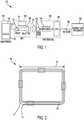
FIG. 2 ,inductor 124 includes one or more rectangular wire bundle(s) 125 of approximately 40x30 mm outside dimensions with a 3 mm bundle thickness.Inductor 124 has an inductance of such a value that properly timed current pulses reach their maximum value at the end of each pulse. Also, the ratio of inductance and winding resistance values is critical in shaping the current from the driver circuit to result in a magnetic field that closely resembles the magnetic signal seen by the magnetic reader head when a magnetic stripe card is swiped in front of it. In one example, the ratio of inductance to winding resistance is 80 µH/Ohm. - The physical shape of the inductor ensures that the magnetic flux lines are spread over a large enough area to include the sensing aperture of the reader head. The inductor windings may be enamel insulated magnet wire, or alternatively, the inductor may be implemented as a spiral inductor formed by conductor traces laid out on rigid or flexible printed circuit substrates.
- Although the inductor is stationary, the inductor is driven by a series of timed current pulses that result in a series of magnetic pulses that resemble the fluctuating magnetic field created by a moving magnetic stripe. The modulation of the field follows the standard magnetic stripe encoding, which in turn results in a stream of electrical pulses on the reader's output that is identical to what would be obtained from a magnetic stripe.
- The key benefit of MST is that it works with the existing infrastructure of point of sale card payment terminals. Unlike with NFC or 2D barcode, no external reader or new terminal has to be installed.
- Referring to
FIG. 1 , asystem 100, comprises asuitable driver 122 andinductor 124 contained in asmall capsule 120, which is connected to the audio jack 1 12 of the phone 1 10. Smartphone 1 10 is loaded with awallet software application 102. The phone 1 10 is connected to theMagstripe Transmitter 120 via its audio jack 1 12. To make a payment at a point of sale location equipped with a common card payment terminal capable of reading standard ISO/ABAmagnetic stripe cards 140 the consumer selects thewallet application 102 on hissmartphone 110 and selects one of the preloaded payment cards (i.e., Visa, MasterCard, Amex) he wants to use for the payment. He holds the phone close (2.5 to 5 cm (1 to 2 inches)) to the point ofsale terminal 140 and presses the pay icon/key 104 on thephone 110. Thewallet application 102 in thephone 110 sends to theMST 120 via the audio jack 112 a stream of pulses that contain the selected card's magnetic stripe data. TheMST 120 amplifies, shapes and emits the pulses in the form of suitably modulated high energymagnetic impulses 130. Themagnetic impulses 130 are picked up by themagstripe reader head 142 located in the point ofsale payment terminal 140 and are converted into electrical pulses. The resulting electrical pulses are decoded bydecoder 144 and processed by its central processing unit (CPU) 146, just like it would process a standard magnetic stripe card that was swiped through its reader slot. The merchant enters the payment amount and the transaction is sent by thePOS terminal 140 via thenetwork 150 to thepayment transaction processor 160. Thetransaction processor 160 returns the transaction authorization and thePOS terminal 140 prints a receipt. With the exception of the card entry method, the entire transaction is completed in the same manner as with a standard magnetic stripe card. - In another example of
MST 120, security is improved by the smartphone supplementing the transaction transmitted through the payment terminal with a separate secure wireless message sent to the processor, where the two transactions are combined for the purposes of authentication. - Referring to
FIG. 3 , in another example, theMST 120 is integrated with a magnetic stripe reader (MSR)head 142a, creating a single device able to both read and transmit magnetic stripe information. The combination of the MST and MSR in conjunction with anelectronic wallet 102, provides a convenient and secure means of loading payment cards into an electronic wallet and the subsequent transmission of the payment card data to aPOS system 140. Furthermore, this example allows convenient person to person payments using credit or debit cards, where each person is equipped with an MST and is able to transmit his card information into the other person's mobile phone with the card reader included in that person's MST. - In another example, magnetic stripe transmission is used to transmit tokenized card data to the point of sale terminal. In this example, the actual payment card number or part of it is substituted by a cryptographically generated token, which is formatted as track data, including token data formatted to resemble a standard Primary Account Number (PAN). The PAN may contain a valid Bank Identification Number (BIN). Such token is either downloaded from the card issuer, another online source, or is locally generated. The MST transmission of tokens replaces the transmission of valid card numbers by transmitting cryptographically generated tokens that are valid only for one transaction and thus eliminates the security risk inherent in the standard magnetic stripe, all without the need to change the existing point of sale hardware. In other examples, more than one track data are transmitted in order to increase compatibility with existing point of sale hardware and software. In these examples, the transmission of Track 1 data may be followed by the transmission of Track 2 data, or Track 2 data may be followed by Track 1 data.
- In a further example, the
MST 120 also contains asecure microcontroller 126 which provides secure local storage of the card data and directly drives theinductor driver circuit 122. This example allows the MST to operate detached from the phone in a store-and-transmit mode. In some examples, the MST further includes volatile and nonvolatile memory for the secure storage of card data and other personal information. - Yet another possible implementation uses Bluetooth™ communications between the
phone 110 and theMST 120, where two-way communications is used for enhanced security and flexibility, including the retrieval by the phone of card data stored in the secure element formed by the MST'ssecure microcontroller 126. - In yet another possible implementation the
MST 120 uses its built-insecure microcontroller 126 to encrypt, either partially or fully, the card data and transmits it via the magnetic field to the point of sale card reader. - In yet another possible implementation the payment card data comprise card verification value (CVV) data that are changed dynamically. In this case, the security of a transaction is improved due to the dynamic changing of the CVV data.
- Referring to
FIG. 4 , in anothersystem 100, is disclosed, in which Magstripe Transmitter (MST) 120 includes awave shaper 121, abipolar driver 123 and aloop inductor 124.Smartphone 110 is loaded with awallet software application 102, and is connected to theMagstripe Transmitter 120 via itsaudio jack 112. To make a payment at a point of sale location equipped with a common card payment terminal capable of reading standard ISO/ABAmagnetic stripe cards 140, the consumer selects thewallet application 102 on hissmartphone 110 and selects one of the pre-loaded payment cards (i.e., Visa, MasterCard, Amex) he wants to use for the payment. He holds the phone close (2.5 to 5 cm (1 to 2 inches)) to the point ofsale terminal 140 and presses the pay icon/key 104 on thephone 110. Thewallet application 102 in thephone 110 sends to theMST 120 via the audio jack a stream of pulses that contain the selected card's magnetic stripe data. TheMST 120 amplifies, shapes and emits the pulses in the form of suitably modulated high energymagnetic impulses 130. Themagnetic impulses 130 are picked up by themagstripe reader head 142 located in the point ofsale payment terminal 140 and are converted into electrical pulses. The resulting electrical pulses are decoded bydecoder 144 and processed by its central processing unit (CPU) 146, just like it would process a standard magnetic stripe card that was swiped through its reader slot. The merchant enters the payment amount and the transaction is sent by thePOS terminal 140 via thenetwork 150 to thepayment transaction processor 160. Thetransaction processor 160 returns the transaction authorization and thePOS terminal 140 prints a receipt. With the exception of the card entry method, the entire transaction is completed in the same manner as with a standard magnetic stripe card. - The magnetic stripe reader-heads used in point of sale terminals are designed to be sensitive only to magnetic fields that originate close to and within their sensing aperture, which is located right in front of the head. They are designed to ignore external magnetic fields outside this sensing aperture. The intended pick-up distance is a fraction of an inch and the field of sensitivity is only a few degrees wide. Additionally, reader heads are surrounded by a
metal shield 141 that greatly attenuates changing magnetic fields outside the head's intended sensing aperture, shown inFIG. 4 . Further, theshield 141 is connected to the terminal's frame ground, which shunts to ground coupled common mode signals originating externally. These design features are aimed at ensuring that the head does not pick up noise from nearby electrical equipment, transmitters or cell-phones. These same design features also prevent remote induction of card data when using an ordinary inductor and pulses that resemble those generated by a moving magnetic stripe. - Accordingly, penetrating the shielding 141 of the reader-head from a distance longer than 13 mm (0.5 inches), and from most angles, requires special techniques, which are the subject of this disclosure. These techniques assure that the signal reaching the head's internal inductor is free of distortion and have the right shape and timings. In order to meet these requirements, the
MST 120 pre-shapes the waves with thewave shaper 121 to compensate for the effects of the shielding, eddy currents and the limited inductance of thereader head 142. Referring toFIG. 5 , a large DC component 81 is added to the inductor current 80 to compensate for the rapidly collapsing magnetic fields inside the head's 142 shieldedenclosure 141 and the effects of the relatively low inductance of the reader-head winding. Additionally, the reader-head amplifier has limited bandwidth. To achieve sufficient induced signal amplitudes, thepulse rise times 82 is controlled to be between 10 and 60 microseconds. This ensures that that the pulse rise times fall within the bandwidth of the reader-head amplifier but not outside the timing constraints of the decoder circuit. - Furthermore, in order to achieve the required penetration from a distance larger than 13 mm (0.5 inches), a
suitable driver 123 must deliver magnetic pulses having a large enough current, that exceeds 1 Ampere peak. Additionally, to create the right output on the reader-head, the current must be bipolar and must contain a large DC component, which is in excess of 40% of the peak current. - The
inductive device 124 of the MST is specially designed to form a loosely coupled transformer, from a distance longer than 13 mm (0.5 inches), with the card reader-head 142, where the MST'sinductor 124 is the primary and the reader-head's inductor is the secondary. Because the coupling between this primary and secondary is very loose, and because of the high losses caused by the head's shielding 141, as well as the losses caused by eddy currents, the current driving the inductor must be of a special level and shape. The magnetic field thus generated must be of a sufficient intensity that these losses are compensated for and sufficient signal is induced into the reader head's inductor. - Therefore
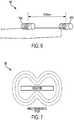
inductor 124 is designed to have a very specific set of characteristics to make it suitable for the transmission function. It has low enough winding resistance to allow the large current needed to generate the intense magnetic field. At the same time, it has sufficient inductance to control the rise time of the current pulses. The inductance required mandates a large number of turns (over 20), without increasing the winding resistance beyond 3 ohms. Concurrent with that, the inductor is shaped to provide a sufficiently well distributed magnetic field with few nulls, as shown inFIG. 7 . Such an inductor is either a single inductor that encloses a large area (between 600 and 1700 square mm), shown inFIG. 2 , or anarray 180 of spatially distributed two ormore inductors FIG. 6 . The inductor (or inductors) may have either, iron or ferrite core(s), which is designed such as to not saturate under the high current driven through the inductor(s). In one example, theinductor 124 has alength 92 in the range between 15 mm to 50 mm. In another example, theMST 120 includes anarray 180 of twoinductors - The traditional magnetic stripe data format does not contain features that protect it against copying. While the MST transmits the card data in a magnetic stripe format, the actual data transmitted does not have to be identical to the data contained in the magnetic stripe of the physical card.
- The MST invention includes a secure transmission option where the card data is suitably modified by replacing part of the discretionary data field with a cryptographically generated dynamic element. This security data element, generated either in the phone or in the hardware of the MST, contains a secure hash which is generated using the card data, the MST ID and a sequence number that is incremented for each transmission, and encrypted by a Key supplied by either the card issuer of another third party. The issuer of the Key is able to calculate this secure hash, using the Key, and thus able to verify that a transaction has originated from a legitimate device using legitimate card data. Because the secure hash changes with every transaction in an unpredictable way, a fraudster (who does not know the Key) cannot calculate a valid hash for a new transaction. As each transaction contains a sequence number, the recipient is able to identify a replay. Also, because the secure hash replaces a crucial part of the original discretionary data field, data captured from an MST transaction is unsuitable for creating a valid counterfeit card.
- By modifying only the part of the card data which is not used by the retailer and the acquirer, this scheme preserves compatibility with existing retail POS and acquirer processing system.
- Referring to
FIG. 8 , in an embodiment of thisinvention 100, Magstripe Transmitter (MST) 120 further includes a payment button ("Button Pay") 170.Button Pay 170 is programmed to be associated with a specific pre-selected payment card that is stored in an electronic wallet. Theelectronic wallet 102 or 102' may be located in themobile phone 110 or theMST 120, as shown inFIG. 8 . Pressing theButton Pay 170 causes the data of the specific pre-selected payment card to be transmitted to the point ofsale payment terminal 140. Accordingly, in order to make a payment at a point of sale location equipped with a common card payment terminal capable of reading standard ISO/ABAmagnetic stripe cards 140, the consumer presses theButton Pay 170 on theMST 120 and the system automatically selects the pre-programmed and pre-selected specific payment card that is associated with theButton Pay 170 and this causes themobile phone 110 to send a stream of pulses that contain the pre-selected card's magnetic stripe data to theMST 120. The stream of pulses that contain the pre-selected card's magnetic stripe data are amplified, shaped and emitted by the MST in the form of suitably modulated high energymagnetic impulses 130. Themagnetic impulses 130 are picked up by the mag-stripe reader head 142 located in the point ofsale payment terminal 140 and are converted into electrical pulses. The resulting electrical pulses are decoded bydecoder 144 and processed by its central processing unit (CPU) 146. The merchant enters the payment amount and the transaction is sent by thePOS terminal 140 via thenetwork 150 to thepayment transaction processor 160. Thetransaction processor 160 returns the transaction authorization and thePOS terminal 140 prints a receipt. Other embodiments include one or more of the following.Key 104 in themobile phone 110 is programmed to be associated with a specific payment card and functions as a Button Pay. The user is notified by the mobile phone that the Button Pay was activated. The MST device is detached from the mobile phone and the Button Pay is remotely activated via the mobile phone's Bluetooth network. - Button Pay is very convenient to use because the consumer does not need to open the electronic wallet and select a card, or does not need to pull out the physical wallet and a card to present to the cashier. This convenience leads to changes in consumer behavior that could be very important to card issuers. Normally, with a physical or electronic wallet, the consumer has a relatively easy choice of pulling out or selecting one of a number of cards in his wallet, normally based on some "strategy" (Amex for entertainment, Visa for purchases, Visa debit for the groceries, etc.). Button Pay provides very convenient access to one card and therefore that card is used for everything. Button Pay changes the relatively level playing field offered by a conventional or electronic wallet in favor of one particular card. The average time for paying with the Button Pay is 3-4 seconds, whereas the average time for paying with a physical card is 17-22 seconds and the average time for paying with a card stored in an electronic wallet is 14-17 seconds.
- Several examples and embodiments of the present invention have been described. Nevertheless, it will be understood that various modifications may be made without departing from the scope of the invention as defined by the accompanying claims.
Claims (28)
- A magnetic stripe transmission (MST) device (120) comprising:a driver (122);an inductor (124);wherein the MST device (120) is configured to receive a stream of pulses comprising magnetic stripe data of a payment card, to shape and amplify the received stream of pulses and to generate and emit magnetic pulses comprising the magnetic stripe data of the payment card;characterized in that the device further comprises a payment button (170) located in the MST device (120) and programmed to be associated with a pre-selected payment card; andwherein activating the payment button (170) causes the MST device (120) to receive a stream of pulses comprising magnetic stripe data of the preselected payment card, to shape and amplify the received stream of pulses and to generate and emit magnetic pulses (130) comprising the magnetic stripe data of the preselected payment card,wherein the magnetic pulses are formatted to be compatible with and to be contactlessly picked up by an existing infrastructure of a magnetic stripe reader head (142) located in a point of sale (POS) payment terminal (140).
- The MST device of claim 1, wherein the magnetic stripe data of the preselected payment card are stored in a memory of the MST device (120).
- The MST device of claim 1, wherein the magnetic stripe data of the preselected payment card are stored in a memory of a mobile phone (110).
- The MST device of any preceding claim,
wherein the driver (122) is configured to output a series of timed current pulses associated with magnetic stripe data of the pre-selected payment card; and
wherein the inductor (124) has one or more windings (125) configured to emit magnetic pulses based on the series of timed current pulses,
wherein the inductor (124) is configured to cause the series of timed current pulses for having a rising time, the one or more windings (125) of the inductor to generate the magnetic pulses. - The MST device of claim 4, wherein the windings of the inductor (124) are formed on a planar substrate layer.
- The MST device of claim 4, wherein the inductor (124) comprises a plurality of loop windings laid out on a printed circuit board substrate.
- The MST device of claim 6, wherein the loop windings comprise rectangular wire bundles (125).
- The MST device of any preceding claim, wherein:the magnetic stripe data of the pre-selected payment card comprise first data corresponding to first track data and second data corresponding to second track data, andthe magnetic pulses, to be received by the magnetic read head (142), are emitted by the inductor (124) in a first sequence comprising transmission of the second data followed by transmission of the first data, and in a second sequence comprising transmission of the first data followed by transmission of the second data.
- The MST device of any of claims 1 to 7, wherein:the magnetic stripe data of the pre-selected payment card comprise first data corresponding to track1 data of track 1 of a standard ISO/ABA magnetic stripe card and second data corresponding to track2 data of track 2 of the standard ISO/ABA magnetic stripe card, andthe magnetic pulses, to be received by the magnetic read head (142), are emitted by the inductor (124) in a first sequence comprising transmission of the first data followed by transmission of the second data, and in a second sequence comprising transmission of the second data followed by transmission of the first data.
- The MST device of any of claims 1 to 7 wherein:the magnetic stripe data of the pre-selected payment card comprise first data corresponding to first track data and second data corresponding to second track data, andthe magnetic pulses, to be received by the magnetic read head (142), are emitted by the inductor (124) in a sequence comprising transmission of the second data followed by transmission of the first data.
- The MST device of any preceding claim, wherein:
the magnetic pulses, to be received by the magnetic read head (142), emitted by the inductor (124) comprise transmission of data generated based on cryptographically generated dynamic element replacing part of the magnetic stripe data. - The MST device of any preceding claim, wherein the driver (122) comprises a bipolar driver to generate bipolar current pulses exceeding 1 Ampere peak.
- An apparatus comprising:the MST device of any preceding claim;a memory for storing a wallet application (102; 102') and information regarding a plurality of payment cards including the pre-selected payment card; anda controller configured to:execute the wallet application (102; 102') to select one of the plurality of payment cards based on a user input and to transmit a first stream of pulses associated with first magnetic stripe data of the selected payment card; andtransmit a second stream of pulses associated with second magnetic stripe data of the pre-selected payment card in response to an activation of the payment button (170) without opening the wallet application (102; 102') for selection of one of the plurality of payment cards;wherein the driver (122) is configured to output a first series of timed current pulses in response to the first stream of pulses, and to output a second series of timed current pulses in response to the second stream of pulses.
- The apparatus of claim 13, wherein the controller is configured to encrypt payment card information using a token downloaded from a card issuer, which is valid only for one magnetic stripe transmission transaction.
- The apparatus of claim 13, wherein the controller is configured to:receive a key supplied by a card issuer or another third party, andencrypt payment card information using the key prior to transmission.
- The MST device of any of claims 4 to 12, when incorporating the features of claim 4:wherein the inductor (124) has an inductance value coupled to the driver (122), which when driven by the output of the series of timed current pulses from the driver (122) results in emission of the magnetic pulses having a rising time that emulates fluctuating magnetic field created by a moving magnetic stripe.
- The MST device of claim 16, further comprising:a memory for storing a wallet application (102; 102'),a controller configured to execute the wallet application (102; 102') to select one of a plurality of payment cards based on a user input and to transmit the stream of pulses associated with magnetic stripe data of the selected payment card,wherein the magnetic pulses associated with the magnetic stripe data of the pre-selected payment card are emitted in response to the activating of the payment button without opening the wallet application (102; 102') for selection of one of the plurality of payment cards.
- The MST device of claim 16, further comprising:
a controller, wherein the controller is configured to encrypt payment card information using a token downloaded from a card issuer, which is valid only for one magnetic stripe transmission transaction. - The MST device of claim 16, further comprising:
a controller, wherein the controller is configured to:receive a key supplied by a card issuer or another third party, andencrypt payment card information using the key prior to emission of magnetic pulses corresponding to the payment card information. - A system for a baseband near field magnetic stripe data transmitter comprising:a mobile phone (110) comprising a payment wallet application (102) and being configured to transmit a stream of pulses comprising magnetic stripe data of a pre-selected payment card; anda magnetic stripe transmission (MST) device (120) according to any of claims 1 of 12 or 16 to 19, wherein the MST (120) device is configured to receive the stream of pulses from the mobile phone (110);wherein the inductor (124) is driven by a series of timed current pulses that result in a series of magnetic pulses that resemble the fluctuating magnetic field created by a moving magnetic stripe; andwherein activating of the payment button (170) located in the MST device 120 causes the mobile phone (110) to transmit the stream of pulses comprising the magnetic stripe data of the pre-selected payment card, initiating the emission of magnetic pulses comprising the magnetic stripe data of the pre-selected payment card.
- The system of claim 20, further comprising a the payment button (104) located in the mobile phone (110), wherein the payment button (104) located in the mobile phone is programmed to be associated with the preselected payment card and wherein activating of the payment button (104) located in the mobile phone initiates the emission of the magnetic pulses.
- The system of claim 20 or claim 21, wherein the mobile phone (110) is configured to output a notification that the payment button (170) located in the MST device (120) was activated.
- The system of any of claims 20 to 22, wherein the payment button (170) located in the MST device (120) is configured to be activated remotely via a wireless connection.
- The MST device of any of claims 1 to 12 or 16 to 19, further comprising a wave shaper (121) that receives the stream of pulses from the mobile phone, and shapes the stream of pulses to output shaped pulses to the driver (122) by controlling pulse rise time (82) to be between 10 to 60 microseconds.
- The MST device of claim 24, wherein the wave shaper (121) further shapes the received stream of pulses to add a DC component (81) to the shaped pulses.
- The MST device of any of claims 1 to 12, 16 to 19, 24 or 25, further comprising a magnetic read head (142) comprising a magnetic read head inductor and wherein the inductor (124) of the MST device (120) is configured to form a loosely coupled transformer with the magnetic read head inductor from a distance longer than 12.7 mm (0.5 inches) by having over twenty turns (125) and a winding resistance no greater than three ohms.
- The MST device of any of claims 1 to 12, 16 to 19 or 24 to 26, wherein the driver (122) comprises a bipolar driver to generate bipolar current pulses with peak current exceeding 1 Ampere, and containing a DC component which is in excess of forty percent of peak current, and
wherein the inductor (124) of the MST device (120) comprises an iron or ferrite core and wherein said core is designed not to saturate in response to the bipolar current pulses flowing through the inductor. - The MST device of any of claims 1 to 12, 16 to 19 or 24 to 27,
wherein the inductor (124) comprises one or more windings (125), and wherein said one or more windings are configured to generate magnetic flux lines that are spread over an area between 600 and 1700 square mm.
Priority Applications (1)
| Application Number | Priority Date | Filing Date | Title |
|---|---|---|---|
| EP16200980.7AEP3171319B1 (en) | 2014-07-11 | 2015-07-07 | System and method for a baseband nearfield magnetic stripe data transmitter |
Applications Claiming Priority (2)
| Application Number | Priority Date | Filing Date | Title |
|---|---|---|---|
| US14/329,130US9361613B2 (en) | 2014-02-17 | 2014-07-11 | System and method for a baseband nearfield magnetic stripe data transmitter |
| PCT/US2015/039327WO2016007475A1 (en) | 2014-07-11 | 2015-07-07 | System and method for a baseband nearfield magnetic stripe data transmitter |
Related Child Applications (2)
| Application Number | Title | Priority Date | Filing Date |
|---|---|---|---|
| EP16200980.7ADivision-IntoEP3171319B1 (en) | 2014-07-11 | 2015-07-07 | System and method for a baseband nearfield magnetic stripe data transmitter |
| EP16200980.7ADivisionEP3171319B1 (en) | 2014-07-11 | 2015-07-07 | System and method for a baseband nearfield magnetic stripe data transmitter |
Publications (3)
| Publication Number | Publication Date |
|---|---|
| EP3033711A1 EP3033711A1 (en) | 2016-06-22 |
| EP3033711A4 EP3033711A4 (en) | 2017-04-12 |
| EP3033711B1true EP3033711B1 (en) | 2018-10-31 |
Family
ID=55064752
Family Applications (2)
| Application Number | Title | Priority Date | Filing Date |
|---|---|---|---|
| EP15818818.5ANot-in-forceEP3033711B1 (en) | 2014-07-11 | 2015-07-07 | System and method for a baseband nearfield magnetic stripe data transmitter |
| EP16200980.7AActiveEP3171319B1 (en) | 2014-07-11 | 2015-07-07 | System and method for a baseband nearfield magnetic stripe data transmitter |
Family Applications After (1)
| Application Number | Title | Priority Date | Filing Date |
|---|---|---|---|
| EP16200980.7AActiveEP3171319B1 (en) | 2014-07-11 | 2015-07-07 | System and method for a baseband nearfield magnetic stripe data transmitter |
Country Status (10)
| Country | Link |
|---|---|
| EP (2) | EP3033711B1 (en) |
| JP (2) | JP6122219B2 (en) |
| KR (2) | KR101784122B1 (en) |
| CN (2) | CN105787542B (en) |
| AU (1) | AU2015288021B2 (en) |
| BR (1) | BR112016011488B1 (en) |
| CA (1) | CA2923479C (en) |
| RU (1) | RU2668720C2 (en) |
| SG (2) | SG10201605590PA (en) |
| WO (1) | WO2016007475A1 (en) |
Families Citing this family (21)
| Publication number | Priority date | Publication date | Assignee | Title |
|---|---|---|---|---|
| WO2016106277A2 (en)* | 2014-12-22 | 2016-06-30 | Capital One Services, LLC. | A system, method and apparatus for reprogramming a transaction card |
| KR102553318B1 (en)* | 2016-01-19 | 2023-07-10 | 삼성전자주식회사 | Device for Performing Transaction and Method Thereof |
| US10417630B2 (en) | 2016-07-28 | 2019-09-17 | Samsung Electronics Co., Ltd. | Transmission-pulse sequence including proxy for secondary magnetic stripe |
| US9697450B1 (en)* | 2016-07-29 | 2017-07-04 | Alpha And Omega Semiconductor Incorporated | Magnetic stripe data transmission system and method for reliable data transmission and low power consumption |
| KR102646761B1 (en)* | 2016-09-07 | 2024-03-13 | 삼성전자주식회사 | Method and electronic device for registration of financial account and payment using the same |
| US10846579B2 (en) | 2016-10-13 | 2020-11-24 | Samsung Electronics Co., Ltd. | Apparatus and method for emitting magnetic signal using plurality of frequencies |
| KR102583254B1 (en) | 2016-10-27 | 2023-09-27 | 삼성전자주식회사 | Semiconductor integrated circuit, operating method thereof, and electronic device including including the same |
| CN108736719B (en)* | 2017-04-14 | 2020-08-07 | 瑞尼斯股份有限公司 | Method for improving MST driver transmission efficiency and driver device for MST driver transmission efficiency |
| CN107316191A (en)* | 2017-05-10 | 2017-11-03 | 上海易码信息科技有限公司 | The information transceiving device of magnetic and the information transmitting methods of magnetic and transfer account method |
| KR20180129449A (en)* | 2017-05-26 | 2018-12-05 | 삼성전기주식회사 | Terminal for mst and electromagnetic wave shield structure therefor |
| FR3067492B1 (en) | 2017-06-13 | 2019-07-19 | Ingenico Group | METHOD OF TRANSMITTING DATA TO A MAGNETIC READING HEAD, RECEIVED DATA PROCESSING METHOD, PAYMENT TERMINAL AND PROGRAM THEREOF |
| KR102395069B1 (en)* | 2017-06-19 | 2022-05-09 | 삼성전자주식회사 | A magnetic secure transmission device and an electronic device comprising that |
| KR102323560B1 (en)* | 2017-08-08 | 2021-11-08 | 삼성전자주식회사 | Electronic device including circuit configured to adjust peak intensity of current |
| KR101840013B1 (en)* | 2017-10-20 | 2018-03-19 | 주식회사 단솔플러스 | Proximity payment system using inaudible sound wave technology |
| KR102066727B1 (en)* | 2017-11-02 | 2020-01-15 | 주식회사 지니틱스 | Magnetic stripe transmitter driving device with low power consumption with limited maximum value of a driving current |
| KR102044214B1 (en)* | 2017-11-17 | 2019-11-13 | 주식회사 지니틱스 | Magnetic stripe transmitter driving device with low power consumption using current shaper |
| US11202604B2 (en) | 2018-04-19 | 2021-12-21 | University Of South Florida | Comprehensive and context-sensitive neonatal pain assessment system and methods using multiple modalities |
| WO2019204700A1 (en) | 2018-04-19 | 2019-10-24 | University Of South Florida | Neonatal pain identification from neonatal facial expressions |
| RU196149U1 (en)* | 2019-12-17 | 2020-02-18 | Общество с ограниченной ответственностью "ПРИССКО" | UNIVERSAL USER ACCESS CARD READER |
| CN112396779A (en)* | 2020-11-06 | 2021-02-23 | 中国农业银行股份有限公司四川省分行 | Multifunctional safety payment device for internet financial business |
| KR102810139B1 (en)* | 2023-11-24 | 2025-05-19 | 한국정보통신주식회사 | Payment method using magnetic stripe transmission and device for performing the same |
Family Cites Families (17)
| Publication number | Priority date | Publication date | Assignee | Title |
|---|---|---|---|---|
| US4798322A (en)* | 1986-04-28 | 1989-01-17 | American Telephone And Telegraph Company | Card reader/writer station for use with a personal memory card using differential data transfer |
| RU2232418C2 (en)* | 1998-04-17 | 2004-07-10 | Дайболд, Инкорпорейтед | Device for executing financial transactions |
| EP1232469B1 (en)* | 1999-11-15 | 2006-03-08 | C-Sam, Inc. | Point of sale and display adapter for electronic transaction device |
| US20030155966A1 (en)* | 2002-02-20 | 2003-08-21 | Harrison Reid R. | Low-power, low-noise CMOS amplifier |
| US7543739B2 (en)* | 2003-12-17 | 2009-06-09 | Qsecure, Inc. | Automated payment card fraud detection and location |
| US7641124B2 (en)* | 2003-12-17 | 2010-01-05 | Qsecure, Inc. | Magnetic data recording device |
| US7357319B1 (en)* | 2005-01-24 | 2008-04-15 | Vivotech, Inc. | External adapter for magnetic stripe card reader |
| US7581678B2 (en) | 2005-02-22 | 2009-09-01 | Tyfone, Inc. | Electronic transaction card |
| US20080126260A1 (en)* | 2006-07-12 | 2008-05-29 | Cox Mark A | Point Of Sale Transaction Device With Magnetic Stripe Emulator And Biometric Authentication |
| CN102460520B (en)* | 2009-05-03 | 2015-01-21 | 洛格摩提公司 | A payment terminal using a mobile communication device, such as a mobile phone, and method for directly debit payment transaction |
| US8523059B1 (en)* | 2009-10-20 | 2013-09-03 | Dynamics Inc. | Advanced payment options for powered cards and devices |
| US8788418B2 (en)* | 2010-03-02 | 2014-07-22 | Gonow Technologies, Llc | Portable E-wallet and universal card |
| US8376239B1 (en)* | 2011-07-08 | 2013-02-19 | Thomas David Humphrey | Method of use of a simulated magnetic stripe card system for use with magnetic stripe card reading terminals |
| CN202267993U (en)* | 2011-09-30 | 2012-06-06 | 重庆南天数据资讯服务有限公司 | System for implementing mobile communication terminal-based point-of-sale (POS) card swiping payment device |
| CN102509218B (en)* | 2011-09-30 | 2017-04-26 | 重庆南天数据资讯服务有限公司 | System implementation method for realizing POS (point-of-sale) card swiping payment device based on mobile communication terminal |
| US8690059B1 (en)* | 2013-01-20 | 2014-04-08 | George Wallner | System and method for a baseband nearfield magnetic stripe data transmitter |
| US8814046B1 (en)* | 2013-03-14 | 2014-08-26 | Looppay Inc | System and method for a baseband nearfield magnetic stripe data transmitter |
- 2015
- 2015-07-07EPEP15818818.5Apatent/EP3033711B1/ennot_activeNot-in-force
- 2015-07-07CNCN201610115716.5Apatent/CN105787542B/enactiveActive
- 2015-07-07AUAU2015288021Apatent/AU2015288021B2/ennot_activeCeased
- 2015-07-07CACA2923479Apatent/CA2923479C/ennot_activeExpired - Fee Related
- 2015-07-07RURU2016114291Apatent/RU2668720C2/enactive
- 2015-07-07KRKR1020167010384Apatent/KR101784122B1/enactiveActive
- 2015-07-07EPEP16200980.7Apatent/EP3171319B1/enactiveActive
- 2015-07-07KRKR1020167031222Apatent/KR101775305B1/enactiveActive
- 2015-07-07WOPCT/US2015/039327patent/WO2016007475A1/enactiveApplication Filing
- 2015-07-07SGSG10201605590PApatent/SG10201605590PA/enunknown
- 2015-07-07SGSG11201603051RApatent/SG11201603051RA/enunknown
- 2015-07-07JPJP2016524421Apatent/JP6122219B2/ennot_activeExpired - Fee Related
- 2015-07-07CNCN201580000203.3Apatent/CN105474229B/ennot_activeExpired - Fee Related
- 2015-07-07BRBR112016011488-4Apatent/BR112016011488B1/enactiveIP Right Grant
- 2016
- 2016-06-14JPJP2016118204Apatent/JP6122182B2/ennot_activeExpired - Fee Related
Non-Patent Citations (1)
| Title |
|---|
| None* |
Also Published As
| Publication number | Publication date |
|---|---|
| WO2016007475A1 (en) | 2016-01-14 |
| CN105474229B (en) | 2019-08-23 |
| JP6122182B2 (en) | 2017-04-26 |
| HK1217554A1 (en) | 2017-01-13 |
| BR112016011488A8 (en) | 2020-04-28 |
| AU2015288021A1 (en) | 2016-03-24 |
| CN105787542B (en) | 2021-08-24 |
| RU2668720C2 (en) | 2018-10-02 |
| CA2923479A1 (en) | 2016-01-14 |
| SG10201605590PA (en) | 2016-08-30 |
| AU2015288021B2 (en) | 2017-04-13 |
| KR20160133008A (en) | 2016-11-21 |
| JP2017500626A (en) | 2017-01-05 |
| EP3033711A4 (en) | 2017-04-12 |
| CN105787542A (en) | 2016-07-20 |
| CA2923479C (en) | 2018-02-20 |
| CN105474229A (en) | 2016-04-06 |
| BR112016011488B1 (en) | 2023-03-21 |
| RU2016114291A (en) | 2017-10-18 |
| JP6122219B2 (en) | 2017-04-26 |
| EP3033711A1 (en) | 2016-06-22 |
| JP2016186802A (en) | 2016-10-27 |
| KR20160058913A (en) | 2016-05-25 |
| KR101784122B1 (en) | 2017-11-06 |
| EP3171319A1 (en) | 2017-05-24 |
| EP3171319B1 (en) | 2019-09-18 |
| SG11201603051RA (en) | 2016-05-30 |
| KR101775305B1 (en) | 2017-09-05 |
Similar Documents
| Publication | Publication Date | Title |
|---|---|---|
| EP3033711B1 (en) | System and method for a baseband nearfield magnetic stripe data transmitter | |
| US9652642B2 (en) | Magnetic secure transmission device hardware | |
| AU2015218340B2 (en) | Baseband nearfield magnetic stripe data transmitter | |
| EP2946334B1 (en) | System and method for a baseband nearfield magentic stripe data transmitter | |
| HK1228061A1 (en) | Magnetic secure transmission device hardware | |
| HK1228061A (en) | Magnetic secure transmission device hardware | |
| HK1228061B (en) | Magnetic secure transmission device hardware | |
| HK1217554B (en) | System and method for a baseband nearfield magnetic stripe data transmitter |
Legal Events
| Date | Code | Title | Description |
|---|---|---|---|
| PUAI | Public reference made under article 153(3) epc to a published international application that has entered the european phase | Free format text:ORIGINAL CODE: 0009012 | |
| 17P | Request for examination filed | Effective date:20160307 | |
| AK | Designated contracting states | Kind code of ref document:A1 Designated state(s):AL AT BE BG CH CY CZ DE DK EE ES FI FR GB GR HR HU IE IS IT LI LT LU LV MC MK MT NL NO PL PT RO RS SE SI SK SM TR | |
| AX | Request for extension of the european patent | Extension state:BA ME | |
| REG | Reference to a national code | Ref country code:DE Ref legal event code:R079 Ref document number:602015019290 Country of ref document:DE Free format text:PREVIOUS MAIN CLASS: G06K0007080000 Ipc:G06Q0020360000 | |
| A4 | Supplementary search report drawn up and despatched | Effective date:20170313 | |
| RIC1 | Information provided on ipc code assigned before grant | Ipc:G06Q 20/32 20120101ALI20170307BHEP Ipc:G06Q 20/36 20120101AFI20170307BHEP Ipc:G06Q 20/38 20120101ALI20170307BHEP Ipc:G06K 19/06 20060101ALI20170307BHEP | |
| DAV | Request for validation of the european patent (deleted) | ||
| DAX | Request for extension of the european patent (deleted) | ||
| STAA | Information on the status of an ep patent application or granted ep patent | Free format text:STATUS: EXAMINATION IS IN PROGRESS | |
| 17Q | First examination report despatched | Effective date:20180116 | |
| GRAP | Despatch of communication of intention to grant a patent | Free format text:ORIGINAL CODE: EPIDOSNIGR1 | |
| STAA | Information on the status of an ep patent application or granted ep patent | Free format text:STATUS: GRANT OF PATENT IS INTENDED | |
| INTG | Intention to grant announced | Effective date:20180508 | |
| GRAS | Grant fee paid | Free format text:ORIGINAL CODE: EPIDOSNIGR3 | |
| RAP1 | Party data changed (applicant data changed or rights of an application transferred) | Owner name:SAMSUNG ELECTRONICS CO., LTD. | |
| GRAA | (expected) grant | Free format text:ORIGINAL CODE: 0009210 | |
| STAA | Information on the status of an ep patent application or granted ep patent | Free format text:STATUS: THE PATENT HAS BEEN GRANTED | |
| AK | Designated contracting states | Kind code of ref document:B1 Designated state(s):AL AT BE BG CH CY CZ DE DK EE ES FI FR GB GR HR HU IE IS IT LI LT LU LV MC MK MT NL NO PL PT RO RS SE SI SK SM TR | |
| REG | Reference to a national code | Ref country code:CH Ref legal event code:EP Ref country code:GB Ref legal event code:FG4D | |
| REG | Reference to a national code | Ref country code:AT Ref legal event code:REF Ref document number:1060289 Country of ref document:AT Kind code of ref document:T Effective date:20181115 | |
| REG | Reference to a national code | Ref country code:IE Ref legal event code:FG4D | |
| REG | Reference to a national code | Ref country code:DE Ref legal event code:R096 Ref document number:602015019290 Country of ref document:DE | |
| REG | Reference to a national code | Ref country code:NL Ref legal event code:FP | |
| REG | Reference to a national code | Ref country code:LT Ref legal event code:MG4D | |
| REG | Reference to a national code | Ref country code:AT Ref legal event code:MK05 Ref document number:1060289 Country of ref document:AT Kind code of ref document:T Effective date:20181031 | |
| PG25 | Lapsed in a contracting state [announced via postgrant information from national office to epo] | Ref country code:ES Free format text:LAPSE BECAUSE OF FAILURE TO SUBMIT A TRANSLATION OF THE DESCRIPTION OR TO PAY THE FEE WITHIN THE PRESCRIBED TIME-LIMIT Effective date:20181031 Ref country code:PL Free format text:LAPSE BECAUSE OF FAILURE TO SUBMIT A TRANSLATION OF THE DESCRIPTION OR TO PAY THE FEE WITHIN THE PRESCRIBED TIME-LIMIT Effective date:20181031 Ref country code:BG Free format text:LAPSE BECAUSE OF FAILURE TO SUBMIT A TRANSLATION OF THE DESCRIPTION OR TO PAY THE FEE WITHIN THE PRESCRIBED TIME-LIMIT Effective date:20190131 Ref country code:HR Free format text:LAPSE BECAUSE OF FAILURE TO SUBMIT A TRANSLATION OF THE DESCRIPTION OR TO PAY THE FEE WITHIN THE PRESCRIBED TIME-LIMIT Effective date:20181031 Ref country code:AT Free format text:LAPSE BECAUSE OF FAILURE TO SUBMIT A TRANSLATION OF THE DESCRIPTION OR TO PAY THE FEE WITHIN THE PRESCRIBED TIME-LIMIT Effective date:20181031 Ref country code:LT Free format text:LAPSE BECAUSE OF FAILURE TO SUBMIT A TRANSLATION OF THE DESCRIPTION OR TO PAY THE FEE WITHIN THE PRESCRIBED TIME-LIMIT Effective date:20181031 Ref country code:LV Free format text:LAPSE BECAUSE OF FAILURE TO SUBMIT A TRANSLATION OF THE DESCRIPTION OR TO PAY THE FEE WITHIN THE PRESCRIBED TIME-LIMIT Effective date:20181031 Ref country code:NO Free format text:LAPSE BECAUSE OF FAILURE TO SUBMIT A TRANSLATION OF THE DESCRIPTION OR TO PAY THE FEE WITHIN THE PRESCRIBED TIME-LIMIT Effective date:20190131 Ref country code:FI Free format text:LAPSE BECAUSE OF FAILURE TO SUBMIT A TRANSLATION OF THE DESCRIPTION OR TO PAY THE FEE WITHIN THE PRESCRIBED TIME-LIMIT Effective date:20181031 Ref country code:IS Free format text:LAPSE BECAUSE OF FAILURE TO SUBMIT A TRANSLATION OF THE DESCRIPTION OR TO PAY THE FEE WITHIN THE PRESCRIBED TIME-LIMIT Effective date:20190228 | |
| PG25 | Lapsed in a contracting state [announced via postgrant information from national office to epo] | Ref country code:AL Free format text:LAPSE BECAUSE OF FAILURE TO SUBMIT A TRANSLATION OF THE DESCRIPTION OR TO PAY THE FEE WITHIN THE PRESCRIBED TIME-LIMIT Effective date:20181031 Ref country code:SE Free format text:LAPSE BECAUSE OF FAILURE TO SUBMIT A TRANSLATION OF THE DESCRIPTION OR TO PAY THE FEE WITHIN THE PRESCRIBED TIME-LIMIT Effective date:20181031 Ref country code:GR Free format text:LAPSE BECAUSE OF FAILURE TO SUBMIT A TRANSLATION OF THE DESCRIPTION OR TO PAY THE FEE WITHIN THE PRESCRIBED TIME-LIMIT Effective date:20190201 Ref country code:RS Free format text:LAPSE BECAUSE OF FAILURE TO SUBMIT A TRANSLATION OF THE DESCRIPTION OR TO PAY THE FEE WITHIN THE PRESCRIBED TIME-LIMIT Effective date:20181031 Ref country code:PT Free format text:LAPSE BECAUSE OF FAILURE TO SUBMIT A TRANSLATION OF THE DESCRIPTION OR TO PAY THE FEE WITHIN THE PRESCRIBED TIME-LIMIT Effective date:20190301 | |
| PG25 | Lapsed in a contracting state [announced via postgrant information from national office to epo] | Ref country code:CZ Free format text:LAPSE BECAUSE OF FAILURE TO SUBMIT A TRANSLATION OF THE DESCRIPTION OR TO PAY THE FEE WITHIN THE PRESCRIBED TIME-LIMIT Effective date:20181031 Ref country code:IT Free format text:LAPSE BECAUSE OF FAILURE TO SUBMIT A TRANSLATION OF THE DESCRIPTION OR TO PAY THE FEE WITHIN THE PRESCRIBED TIME-LIMIT Effective date:20181031 Ref country code:DK Free format text:LAPSE BECAUSE OF FAILURE TO SUBMIT A TRANSLATION OF THE DESCRIPTION OR TO PAY THE FEE WITHIN THE PRESCRIBED TIME-LIMIT Effective date:20181031 | |
| REG | Reference to a national code | Ref country code:DE Ref legal event code:R097 Ref document number:602015019290 Country of ref document:DE | |
| PG25 | Lapsed in a contracting state [announced via postgrant information from national office to epo] | Ref country code:EE Free format text:LAPSE BECAUSE OF FAILURE TO SUBMIT A TRANSLATION OF THE DESCRIPTION OR TO PAY THE FEE WITHIN THE PRESCRIBED TIME-LIMIT Effective date:20181031 Ref country code:SK Free format text:LAPSE BECAUSE OF FAILURE TO SUBMIT A TRANSLATION OF THE DESCRIPTION OR TO PAY THE FEE WITHIN THE PRESCRIBED TIME-LIMIT Effective date:20181031 Ref country code:RO Free format text:LAPSE BECAUSE OF FAILURE TO SUBMIT A TRANSLATION OF THE DESCRIPTION OR TO PAY THE FEE WITHIN THE PRESCRIBED TIME-LIMIT Effective date:20181031 Ref country code:SM Free format text:LAPSE BECAUSE OF FAILURE TO SUBMIT A TRANSLATION OF THE DESCRIPTION OR TO PAY THE FEE WITHIN THE PRESCRIBED TIME-LIMIT Effective date:20181031 | |
| PLBE | No opposition filed within time limit | Free format text:ORIGINAL CODE: 0009261 | |
| STAA | Information on the status of an ep patent application or granted ep patent | Free format text:STATUS: NO OPPOSITION FILED WITHIN TIME LIMIT | |
| 26N | No opposition filed | Effective date:20190801 | |
| PG25 | Lapsed in a contracting state [announced via postgrant information from national office to epo] | Ref country code:SI Free format text:LAPSE BECAUSE OF FAILURE TO SUBMIT A TRANSLATION OF THE DESCRIPTION OR TO PAY THE FEE WITHIN THE PRESCRIBED TIME-LIMIT Effective date:20181031 | |
| PG25 | Lapsed in a contracting state [announced via postgrant information from national office to epo] | Ref country code:MC Free format text:LAPSE BECAUSE OF FAILURE TO SUBMIT A TRANSLATION OF THE DESCRIPTION OR TO PAY THE FEE WITHIN THE PRESCRIBED TIME-LIMIT Effective date:20181031 | |
| REG | Reference to a national code | Ref country code:CH Ref legal event code:PL | |
| PG25 | Lapsed in a contracting state [announced via postgrant information from national office to epo] | Ref country code:TR Free format text:LAPSE BECAUSE OF FAILURE TO SUBMIT A TRANSLATION OF THE DESCRIPTION OR TO PAY THE FEE WITHIN THE PRESCRIBED TIME-LIMIT Effective date:20181031 | |
| REG | Reference to a national code | Ref country code:BE Ref legal event code:MM Effective date:20190731 | |
| PG25 | Lapsed in a contracting state [announced via postgrant information from national office to epo] | Ref country code:LI Free format text:LAPSE BECAUSE OF NON-PAYMENT OF DUE FEES Effective date:20190731 Ref country code:BE Free format text:LAPSE BECAUSE OF NON-PAYMENT OF DUE FEES Effective date:20190731 Ref country code:CH Free format text:LAPSE BECAUSE OF NON-PAYMENT OF DUE FEES Effective date:20190731 Ref country code:LU Free format text:LAPSE BECAUSE OF NON-PAYMENT OF DUE FEES Effective date:20190707 | |
| PG25 | Lapsed in a contracting state [announced via postgrant information from national office to epo] | Ref country code:FR Free format text:LAPSE BECAUSE OF NON-PAYMENT OF DUE FEES Effective date:20190731 | |
| PG25 | Lapsed in a contracting state [announced via postgrant information from national office to epo] | Ref country code:IE Free format text:LAPSE BECAUSE OF NON-PAYMENT OF DUE FEES Effective date:20190707 | |
| PG25 | Lapsed in a contracting state [announced via postgrant information from national office to epo] | Ref country code:CY Free format text:LAPSE BECAUSE OF FAILURE TO SUBMIT A TRANSLATION OF THE DESCRIPTION OR TO PAY THE FEE WITHIN THE PRESCRIBED TIME-LIMIT Effective date:20181031 | |
| PG25 | Lapsed in a contracting state [announced via postgrant information from national office to epo] | Ref country code:MT Free format text:LAPSE BECAUSE OF FAILURE TO SUBMIT A TRANSLATION OF THE DESCRIPTION OR TO PAY THE FEE WITHIN THE PRESCRIBED TIME-LIMIT Effective date:20181031 Ref country code:HU Free format text:LAPSE BECAUSE OF FAILURE TO SUBMIT A TRANSLATION OF THE DESCRIPTION OR TO PAY THE FEE WITHIN THE PRESCRIBED TIME-LIMIT; INVALID AB INITIO Effective date:20150707 | |
| PGFP | Annual fee paid to national office [announced via postgrant information from national office to epo] | Ref country code:NL Payment date:20210622 Year of fee payment:7 | |
| PGFP | Annual fee paid to national office [announced via postgrant information from national office to epo] | Ref country code:GB Payment date:20210625 Year of fee payment:7 | |
| PG25 | Lapsed in a contracting state [announced via postgrant information from national office to epo] | Ref country code:MK Free format text:LAPSE BECAUSE OF FAILURE TO SUBMIT A TRANSLATION OF THE DESCRIPTION OR TO PAY THE FEE WITHIN THE PRESCRIBED TIME-LIMIT Effective date:20181031 | |
| PGFP | Annual fee paid to national office [announced via postgrant information from national office to epo] | Ref country code:DE Payment date:20220621 Year of fee payment:8 | |
| REG | Reference to a national code | Ref country code:NL Ref legal event code:MM Effective date:20220801 | |
| GBPC | Gb: european patent ceased through non-payment of renewal fee | Effective date:20220707 | |
| PG25 | Lapsed in a contracting state [announced via postgrant information from national office to epo] | Ref country code:GB Free format text:LAPSE BECAUSE OF NON-PAYMENT OF DUE FEES Effective date:20220707 | |
| PG25 | Lapsed in a contracting state [announced via postgrant information from national office to epo] | Ref country code:NL Free format text:LAPSE BECAUSE OF NON-PAYMENT OF DUE FEES Effective date:20220801 | |
| REG | Reference to a national code | Ref country code:DE Ref legal event code:R119 Ref document number:602015019290 Country of ref document:DE | |
| PG25 | Lapsed in a contracting state [announced via postgrant information from national office to epo] | Ref country code:DE Free format text:LAPSE BECAUSE OF NON-PAYMENT OF DUE FEES Effective date:20240201 |