EP3033135B1 - Medical guidewire - Google Patents
Medical guidewireDownload PDFInfo
- Publication number
- EP3033135B1 EP3033135B1EP14755553.6AEP14755553AEP3033135B1EP 3033135 B1EP3033135 B1EP 3033135B1EP 14755553 AEP14755553 AEP 14755553AEP 3033135 B1EP3033135 B1EP 3033135B1
- Authority
- EP
- European Patent Office
- Prior art keywords
- guidewire
- distal
- inflatable balloon
- expandable element
- left ventricle
- Prior art date
- Legal status (The legal status is an assumption and is not a legal conclusion. Google has not performed a legal analysis and makes no representation as to the accuracy of the status listed.)
- Revoked
Links
- 230000007704transitionEffects0.000claimsdescription17
- 239000006260foamSubstances0.000claimsdescription5
- 238000013519translationMethods0.000claimsdescription3
- 210000005240left ventricleAnatomy0.000description63
- 238000000034methodMethods0.000description58
- 210000001765aortic valveAnatomy0.000description32
- 239000000463materialSubstances0.000description24
- 238000003466weldingMethods0.000description19
- 238000011282treatmentMethods0.000description18
- 210000003709heart valveAnatomy0.000description17
- 210000000709aortaAnatomy0.000description16
- 229910001000nickel titaniumInorganic materials0.000description12
- 238000011144upstream manufacturingMethods0.000description12
- 229910045601alloyInorganic materials0.000description11
- 239000000956alloySubstances0.000description11
- 238000000576coating methodMethods0.000description10
- 238000000227grindingMethods0.000description9
- PXHVJJICTQNCMI-UHFFFAOYSA-NnickelSubstances[Ni]PXHVJJICTQNCMI-UHFFFAOYSA-N0.000description8
- 238000002595magnetic resonance imagingMethods0.000description6
- HLXZNVUGXRDIFK-UHFFFAOYSA-Nnickel titaniumChemical compound[Ti].[Ti].[Ti].[Ti].[Ti].[Ti].[Ti].[Ti].[Ti].[Ti].[Ti].[Ni].[Ni].[Ni].[Ni].[Ni].[Ni].[Ni].[Ni].[Ni].[Ni].[Ni].[Ni].[Ni].[Ni]HLXZNVUGXRDIFK-UHFFFAOYSA-N0.000description6
- 238000001356surgical procedureMethods0.000description6
- 210000003484anatomyAnatomy0.000description5
- 230000000694effectsEffects0.000description5
- 239000012530fluidSubstances0.000description5
- 238000003780insertionMethods0.000description5
- 230000037431insertionEffects0.000description5
- 239000000203mixtureSubstances0.000description5
- 230000008569processEffects0.000description5
- 238000002560therapeutic procedureMethods0.000description5
- 239000008280bloodSubstances0.000description4
- 210000004369bloodAnatomy0.000description4
- 238000010276constructionMethods0.000description4
- 229910052751metalInorganic materials0.000description4
- 239000002184metalSubstances0.000description4
- 229910052759nickelInorganic materials0.000description4
- 238000005476solderingMethods0.000description4
- 239000000126substanceSubstances0.000description4
- 239000010936titaniumSubstances0.000description4
- 208000003017Aortic Valve StenosisDiseases0.000description3
- 210000002376aorta thoracicAnatomy0.000description3
- 206010002906aortic stenosisDiseases0.000description3
- 230000009286beneficial effectEffects0.000description3
- 238000005219brazingMethods0.000description3
- 239000011248coating agentSubstances0.000description3
- 210000004351coronary vesselAnatomy0.000description3
- 230000006870functionEffects0.000description3
- 229920001477hydrophilic polymerPolymers0.000description3
- 229910001092metal group alloyInorganic materials0.000description3
- 150000002739metalsChemical class0.000description3
- 229920000642polymerPolymers0.000description3
- 229910052719titaniumInorganic materials0.000description3
- KDLHZDBZIXYQEI-UHFFFAOYSA-NPalladiumChemical compound[Pd]KDLHZDBZIXYQEI-UHFFFAOYSA-N0.000description2
- RTAQQCXQSZGOHL-UHFFFAOYSA-NTitaniumChemical compound[Ti]RTAQQCXQSZGOHL-UHFFFAOYSA-N0.000description2
- 229910001080W alloyInorganic materials0.000description2
- 238000004026adhesive bondingMethods0.000description2
- 229910001566austeniteInorganic materials0.000description2
- 238000005452bendingMethods0.000description2
- 210000000748cardiovascular systemAnatomy0.000description2
- 238000002788crimpingMethods0.000description2
- 238000005520cutting processMethods0.000description2
- 229920002313fluoropolymerPolymers0.000description2
- 239000004811fluoropolymerSubstances0.000description2
- 210000001035gastrointestinal tractAnatomy0.000description2
- 230000002209hydrophobic effectEffects0.000description2
- 238000003384imaging methodMethods0.000description2
- 230000001788irregularEffects0.000description2
- 230000005291magnetic effectEffects0.000description2
- 229910000734martensiteInorganic materials0.000description2
- 230000007246mechanismEffects0.000description2
- 238000012986modificationMethods0.000description2
- 230000004048modificationEffects0.000description2
- 210000000214mouthAnatomy0.000description2
- 210000003800pharynxAnatomy0.000description2
- BASFCYQUMIYNBI-UHFFFAOYSA-NplatinumChemical compound[Pt]BASFCYQUMIYNBI-UHFFFAOYSA-N0.000description2
- 229920001343polytetrafluoroethylenePolymers0.000description2
- 230000002787reinforcementEffects0.000description2
- 210000002345respiratory systemAnatomy0.000description2
- 239000010935stainless steelSubstances0.000description2
- 229910001220stainless steelInorganic materials0.000description2
- WFKWXMTUELFFGS-UHFFFAOYSA-NtungstenChemical compound[W]WFKWXMTUELFFGS-UHFFFAOYSA-N0.000description2
- 229910052721tungstenInorganic materials0.000description2
- 239000010937tungstenSubstances0.000description2
- 210000005166vasculatureAnatomy0.000description2
- 229910001152Bi alloyInorganic materials0.000description1
- SAZNQYYKGDCJGT-YFKPBYRVSA-NCC[C@H](C=C)[N+]([O-])=OChemical compoundCC[C@H](C=C)[N+]([O-])=OSAZNQYYKGDCJGT-YFKPBYRVSA-N0.000description1
- OYPRJOBELJOOCE-UHFFFAOYSA-NCalciumChemical compound[Ca]OYPRJOBELJOOCE-UHFFFAOYSA-N0.000description1
- 229910000531Co alloyInorganic materials0.000description1
- 229910000640Fe alloyInorganic materials0.000description1
- 229910000934Monel 400Inorganic materials0.000description1
- 108091092920SmY RNAProteins0.000description1
- 241001237710SmyrnaSpecies0.000description1
- HZEWFHLRYVTOIW-UHFFFAOYSA-N[Ti].[Ni]Chemical compound[Ti].[Ni]HZEWFHLRYVTOIW-UHFFFAOYSA-N0.000description1
- 238000005299abrasionMethods0.000description1
- 230000002745absorbentEffects0.000description1
- 239000002250absorbentSubstances0.000description1
- 229920000615alginic acidPolymers0.000description1
- 235000010443alginic acidNutrition0.000description1
- 238000002399angioplastyMethods0.000description1
- 230000006399behaviorEffects0.000description1
- 230000005540biological transmissionEffects0.000description1
- 230000017531blood circulationEffects0.000description1
- 230000036760body temperatureEffects0.000description1
- 229910052791calciumInorganic materials0.000description1
- 239000011575calciumSubstances0.000description1
- 150000001720carbohydratesChemical class0.000description1
- 229910052799carbonInorganic materials0.000description1
- 238000005266castingMethods0.000description1
- 229910052804chromiumInorganic materials0.000description1
- 239000011651chromiumSubstances0.000description1
- BIJOYKCOMBZXAE-UHFFFAOYSA-Nchromium iron nickelChemical compound[Cr].[Fe].[Ni]BIJOYKCOMBZXAE-UHFFFAOYSA-N0.000description1
- 239000011247coating layerSubstances0.000description1
- 210000001072colonAnatomy0.000description1
- 238000004891communicationMethods0.000description1
- 230000000295complement effectEffects0.000description1
- 239000002131composite materialSubstances0.000description1
- 150000001875compoundsChemical class0.000description1
- OANFWJQPUHQWDL-UHFFFAOYSA-Ncopper iron manganese nickelChemical compound[Mn].[Fe].[Ni].[Cu]OANFWJQPUHQWDL-UHFFFAOYSA-N0.000description1
- 230000003247decreasing effectEffects0.000description1
- 230000001419dependent effectEffects0.000description1
- 230000008021depositionEffects0.000description1
- 229910003460diamondInorganic materials0.000description1
- 239000010432diamondSubstances0.000description1
- 230000001079digestive effectEffects0.000description1
- 210000002249digestive systemAnatomy0.000description1
- 201000010099diseaseDiseases0.000description1
- 208000037265diseases, disorders, signs and symptomsDiseases0.000description1
- 238000010894electron beam technologyMethods0.000description1
- 229910000701elgiloys (Co-Cr-Ni Alloy)Inorganic materials0.000description1
- 238000005530etchingMethods0.000description1
- 238000001125extrusionMethods0.000description1
- 239000003302ferromagnetic materialSubstances0.000description1
- 239000000945fillerSubstances0.000description1
- 238000002594fluoroscopyMethods0.000description1
- PCHJSUWPFVWCPO-UHFFFAOYSA-NgoldChemical compound[Au]PCHJSUWPFVWCPO-UHFFFAOYSA-N0.000description1
- 229910052737goldInorganic materials0.000description1
- 239000010931goldSubstances0.000description1
- 229910000856hastalloyInorganic materials0.000description1
- 230000036541healthEffects0.000description1
- 208000018578heart valve diseaseDiseases0.000description1
- 238000010438heat treatmentMethods0.000description1
- 125000002768hydroxyalkyl groupChemical group0.000description1
- 239000007943implantSubstances0.000description1
- 238000002513implantationMethods0.000description1
- 229910001119inconels 625Inorganic materials0.000description1
- XEEYBQQBJWHFJM-UHFFFAOYSA-NironSubstances[Fe]XEEYBQQBJWHFJM-UHFFFAOYSA-N0.000description1
- 229910052742ironInorganic materials0.000description1
- 238000005304joiningMethods0.000description1
- 210000002429large intestineAnatomy0.000description1
- 238000003698laser cuttingMethods0.000description1
- 230000003902lesionEffects0.000description1
- 210000004072lungAnatomy0.000description1
- 229910052748manganeseInorganic materials0.000description1
- 238000005459micromachiningMethods0.000description1
- 238000003801millingMethods0.000description1
- 210000004115mitral valveAnatomy0.000description1
- 229910052750molybdenumInorganic materials0.000description1
- 238000000465mouldingMethods0.000description1
- 229910000623nickel–chromium alloyInorganic materials0.000description1
- 230000003287optical effectEffects0.000description1
- 229910052763palladiumInorganic materials0.000description1
- 239000004033plasticSubstances0.000description1
- 229920003023plasticPolymers0.000description1
- 229910052697platinumInorganic materials0.000description1
- 229920000412polyarylenePolymers0.000description1
- 239000002861polymer materialSubstances0.000description1
- 229920001296polysiloxanePolymers0.000description1
- 229920002451polyvinyl alcoholPolymers0.000description1
- 235000019422polyvinyl alcoholNutrition0.000description1
- 230000002685pulmonary effectEffects0.000description1
- 210000003102pulmonary valveAnatomy0.000description1
- 238000011084recoveryMethods0.000description1
- 210000000664rectumAnatomy0.000description1
- 230000008439repair processEffects0.000description1
- 238000009256replacement therapyMethods0.000description1
- 230000000452restraining effectEffects0.000description1
- 238000012552reviewMethods0.000description1
- 238000007789sealingMethods0.000description1
- 210000000813small intestineAnatomy0.000description1
- 239000007787solidSubstances0.000description1
- 229910052715tantalumInorganic materials0.000description1
- GUVRBAGPIYLISA-UHFFFAOYSA-Ntantalum atomChemical compound[Ta]GUVRBAGPIYLISA-UHFFFAOYSA-N0.000description1
- 210000000591tricuspid valveAnatomy0.000description1
- 230000002792vascularEffects0.000description1
- XLYOFNOQVPJJNP-UHFFFAOYSA-NwaterSubstancesOXLYOFNOQVPJJNP-UHFFFAOYSA-N0.000description1
Images


Classifications
- A—HUMAN NECESSITIES
- A61—MEDICAL OR VETERINARY SCIENCE; HYGIENE
- A61F—FILTERS IMPLANTABLE INTO BLOOD VESSELS; PROSTHESES; DEVICES PROVIDING PATENCY TO, OR PREVENTING COLLAPSING OF, TUBULAR STRUCTURES OF THE BODY, e.g. STENTS; ORTHOPAEDIC, NURSING OR CONTRACEPTIVE DEVICES; FOMENTATION; TREATMENT OR PROTECTION OF EYES OR EARS; BANDAGES, DRESSINGS OR ABSORBENT PADS; FIRST-AID KITS
- A61F2/00—Filters implantable into blood vessels; Prostheses, i.e. artificial substitutes or replacements for parts of the body; Appliances for connecting them with the body; Devices providing patency to, or preventing collapsing of, tubular structures of the body, e.g. stents
- A61F2/02—Prostheses implantable into the body
- A61F2/24—Heart valves ; Vascular valves, e.g. venous valves; Heart implants, e.g. passive devices for improving the function of the native valve or the heart muscle; Transmyocardial revascularisation [TMR] devices; Valves implantable in the body
- A61F2/2427—Devices for manipulating or deploying heart valves during implantation
- A—HUMAN NECESSITIES
- A61—MEDICAL OR VETERINARY SCIENCE; HYGIENE
- A61M—DEVICES FOR INTRODUCING MEDIA INTO, OR ONTO, THE BODY; DEVICES FOR TRANSDUCING BODY MEDIA OR FOR TAKING MEDIA FROM THE BODY; DEVICES FOR PRODUCING OR ENDING SLEEP OR STUPOR
- A61M25/00—Catheters; Hollow probes
- A61M25/01—Introducing, guiding, advancing, emplacing or holding catheters
- A61M25/09—Guide wires
- A61M25/0905—Guide wires extendable, e.g. mechanisms for extension
- A—HUMAN NECESSITIES
- A61—MEDICAL OR VETERINARY SCIENCE; HYGIENE
- A61M—DEVICES FOR INTRODUCING MEDIA INTO, OR ONTO, THE BODY; DEVICES FOR TRANSDUCING BODY MEDIA OR FOR TAKING MEDIA FROM THE BODY; DEVICES FOR PRODUCING OR ENDING SLEEP OR STUPOR
- A61M25/00—Catheters; Hollow probes
- A61M25/01—Introducing, guiding, advancing, emplacing or holding catheters
- A61M25/09—Guide wires
- A61M2025/09008—Guide wires having a balloon
- A—HUMAN NECESSITIES
- A61—MEDICAL OR VETERINARY SCIENCE; HYGIENE
- A61M—DEVICES FOR INTRODUCING MEDIA INTO, OR ONTO, THE BODY; DEVICES FOR TRANSDUCING BODY MEDIA OR FOR TAKING MEDIA FROM THE BODY; DEVICES FOR PRODUCING OR ENDING SLEEP OR STUPOR
- A61M25/00—Catheters; Hollow probes
- A61M25/01—Introducing, guiding, advancing, emplacing or holding catheters
- A61M25/09—Guide wires
- A61M2025/091—Guide wires having a lumen for drug delivery or suction
- A—HUMAN NECESSITIES
- A61—MEDICAL OR VETERINARY SCIENCE; HYGIENE
- A61M—DEVICES FOR INTRODUCING MEDIA INTO, OR ONTO, THE BODY; DEVICES FOR TRANSDUCING BODY MEDIA OR FOR TAKING MEDIA FROM THE BODY; DEVICES FOR PRODUCING OR ENDING SLEEP OR STUPOR
- A61M25/00—Catheters; Hollow probes
- A61M25/01—Introducing, guiding, advancing, emplacing or holding catheters
- A61M25/09—Guide wires
- A61M2025/09133—Guide wires having specific material compositions or coatings; Materials with specific mechanical behaviours, e.g. stiffness, strength to transmit torque
- A—HUMAN NECESSITIES
- A61—MEDICAL OR VETERINARY SCIENCE; HYGIENE
- A61M—DEVICES FOR INTRODUCING MEDIA INTO, OR ONTO, THE BODY; DEVICES FOR TRANSDUCING BODY MEDIA OR FOR TAKING MEDIA FROM THE BODY; DEVICES FOR PRODUCING OR ENDING SLEEP OR STUPOR
- A61M25/00—Catheters; Hollow probes
- A61M25/01—Introducing, guiding, advancing, emplacing or holding catheters
- A61M25/09—Guide wires
- A61M2025/0915—Guide wires having features for changing the stiffness
- A—HUMAN NECESSITIES
- A61—MEDICAL OR VETERINARY SCIENCE; HYGIENE
- A61M—DEVICES FOR INTRODUCING MEDIA INTO, OR ONTO, THE BODY; DEVICES FOR TRANSDUCING BODY MEDIA OR FOR TAKING MEDIA FROM THE BODY; DEVICES FOR PRODUCING OR ENDING SLEEP OR STUPOR
- A61M25/00—Catheters; Hollow probes
- A61M25/01—Introducing, guiding, advancing, emplacing or holding catheters
- A61M25/09—Guide wires
- A61M2025/09166—Guide wires having radio-opaque features
- A—HUMAN NECESSITIES
- A61—MEDICAL OR VETERINARY SCIENCE; HYGIENE
- A61M—DEVICES FOR INTRODUCING MEDIA INTO, OR ONTO, THE BODY; DEVICES FOR TRANSDUCING BODY MEDIA OR FOR TAKING MEDIA FROM THE BODY; DEVICES FOR PRODUCING OR ENDING SLEEP OR STUPOR
- A61M25/00—Catheters; Hollow probes
- A61M25/01—Introducing, guiding, advancing, emplacing or holding catheters
- A61M25/09—Guide wires
- A61M2025/09175—Guide wires having specific characteristics at the distal tip
- A61M2025/09183—Guide wires having specific characteristics at the distal tip having tools at the distal tip
- A—HUMAN NECESSITIES
- A61—MEDICAL OR VETERINARY SCIENCE; HYGIENE
- A61M—DEVICES FOR INTRODUCING MEDIA INTO, OR ONTO, THE BODY; DEVICES FOR TRANSDUCING BODY MEDIA OR FOR TAKING MEDIA FROM THE BODY; DEVICES FOR PRODUCING OR ENDING SLEEP OR STUPOR
- A61M2210/00—Anatomical parts of the body
- A61M2210/12—Blood circulatory system
- A61M2210/125—Heart
- A—HUMAN NECESSITIES
- A61—MEDICAL OR VETERINARY SCIENCE; HYGIENE
- A61M—DEVICES FOR INTRODUCING MEDIA INTO, OR ONTO, THE BODY; DEVICES FOR TRANSDUCING BODY MEDIA OR FOR TAKING MEDIA FROM THE BODY; DEVICES FOR PRODUCING OR ENDING SLEEP OR STUPOR
- A61M2210/00—Anatomical parts of the body
- A61M2210/12—Blood circulatory system
- A61M2210/127—Aorta
Definitions
- the disclosurerelates generally to medical devices and more particularly to medical devices that are adapted for use in procedures for repairing heart valves.
- Aortic valve stenosisis a frequent expression of valvular heart disease, and may often be a leading indicator for valve replacement therapy in Europe and the United States. The prevalence of aortic valve stenosis tends to increase in older population groups. In some cases, traditional open-heart valve replacement surgery is not suitable for patients with higher surgical risk factors. Alternate therapies, and/or linking therapies that may transition an at-risk patient to a more suitable condition for traditional open-heart valve replacement surgery, may be beneficial in improving the lifestyle of patients suffering from aortic valve stenosis.
- US 2013/0158655discloses a medical device handle including a handle housing, a rotatable collar, a rotatable control knob and a slidable door disposed about the collar.
- US 2003/163156 A1discloses a guidewire comprising an expandable balloon, which is used to open a stenosed vessel.
- the present inventionpertains to a guidewire system as set forth in the claims.
- the guidewire systemincludes a guidewire having a proximal end, a distal end, and a length extending therebetween, wherein the guidewire includes a relatively stiff proximal section and a relatively flexible distal section joined by a transition region, and a TAVI device slidably disposed on the guidewire, wherein the guidewire includes an expandable element disposed about the transition region in a first position, wherein the expandable element is configured to expand from a collapsed configuration to an expanded configuration.
- medical devices and methods of use in accordance with the disclosurecan be adapted and configured for use in other parts of the anatomy, such as the digestive system, the respiratory system, or other parts of the anatomy of a patient.
- upstream and downstreamrefer to a position or location relative to the direction of blood flow through a particular element or location, such as a vessel (i.e., the aorta), a heart valve (i.e., the aortic valve), and the like.
- a vesseli.e., the aorta
- a heart valvei.e., the aortic valve
- numeric valuesare herein assumed to be modified by the term "about,” whether or not explicitly indicated.
- the term “about”, in the context of numeric values,generally refers to a range of numbers that one of skill in the art would consider equivalent to the recited value (i.e., having the same function or result). In many instances, the term “about” may include numbers that are rounded to the nearest significant figure. Other uses of the term “about” (i.e., in a context other than numeric values) may be assumed to have their ordinary and customary definition(s), as understood from and consistent with the context of the specification, unless otherwise specified.
- Weight percent, percent by weight, wt%, wt-%, % by weight, and the likeare synonyms that refer to the concentration of a substance as the weight of that substance divided by the weight of the composition and multiplied by 100.
- references in the specification to "an embodiment”, “some embodiments”, “other embodiments”, etc.,indicate that the embodiment(s) described may include a particular feature, structure, or characteristic, but every embodiment may not necessarily include the particular feature, structure, or characteristic. Moreover, such phrases are not necessarily referring to the same embodiment. Further, when a particular feature, structure, or characteristic is described in connection with an embodiment, it would be within the knowledge of one skilled in the art to effect such feature, structure, or characteristic in connection with other embodiments, whether or not explicitly described, unless clearly stated to the contrary.
- Some relatively common medical conditionsmay include or be the result of inefficiency, ineffectiveness, or complete failure of one or more of the valves within the heart.
- failure of the aortic valvecan have a serious effect on a human and could lead to a serious health condition and/or death if not dealt with.
- a human heartincludes several different heart valves, including aortic, pulmonary, mitral, and tricuspid valves, which control the flow of blood to and from the heart.
- a heart valvemay become obstructed, narrowed, and/or less flexible (i.e., stenosed) due to hardening, calcium deposition, or other factors, thereby reducing the flow of blood through the valve and/or increasing the pressure within the chambers of the heart as the heart attempts to pump the blood through the vasculature.
- One traditional treatment methodis valve replacement, where the stenosed valve is removed and a replacement tissue or mechanical valve is implanted via open heart surgery.
- Alternative treatmentsincluding percutaneous valve replacement procedures (i.e., transcatheter aortic valve implantation, or TAVI) which may deliver and implant a replacement heart valve (i.e., aortic valve), have been developed which may be much less invasive to the patient.
- TAVItranscatheter aortic valve implantation
- a typical aortic valvemay comprise three leaflets, although two leaflet and four leaflet valves are known to occur in a portion of the population.
- the following discussionwill be described in the context of treating a typical aortic valve.
- the devices and methods described hereinmay be adapted for use in the treatment of a two or four (or more) leaflet heart valve and/or a non-aortic heart valve.
- the relative orientations and directions associated with the described devices and methodsmay be modified to accommodate the specifics (i.e., orientation, location, size, etc.) of the heart valve undergoing treatment.
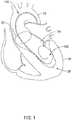
- FIG. 1schematically illustrates a guidewire 100 disposed within an aorta 10, and/or an aortic valve 22 and a left ventricle 24 of a heart 20.
- Treatment of an aortic valve 22 using a TAVI devicemay sometimes involve insertion of a relatively stiff guidewire 100, which may or may not have a relatively flexible distal tip, upstream through the aorta 10 and/or the aortic valve 22 into the left ventricle 24.
- a suitable TAVI devicemay be inserted and/or advanced over the guidewire 100 to the heart 20 and/or the aortic valve 22. As shown in FIG.
- the guidewire 100may extend upstream through the aorta 10, across or through the aortic arch, and through the aortic valve 22 into the left ventricle 24 of a patient's heart 20.
- a distal end 102 of the guidewire 100may be positioned within the left ventricle 24 during a TAVI procedure.
- the guidewire 100may have a substantially solid cross-section.
- the guidewire 100may be tubular or hollow in construction, with one or more lumens disposed therein, such as, for example, a hypotube or a thin-walled tubular catheter.
- the guidewire 100may be formed of any materials suitable for use, dependent upon the desired properties of the guidewire 100.
- suitable materialsinclude metals, metal alloys, polymers, composites, or the like, or combinations or mixtures thereof.
- suitable metals and metal alloysinclude stainless steel, such as 304V, 304L, and 316L stainless steel; alloys including nickel-titanium alloy such as linear elastic or superelastic (i.e., pseudoelastic) nitinol; nickel-chromium alloy; nickel-chromium-iron alloy; cobalt alloy; tungsten or tungsten alloys; MP35-N (having a composition of about 35% Ni, 35% Co, 20% Cr, 9.75% Mo, a maximum 1% Fe, a maximum 1% Ti, a maximum 0.25% C, a maximum 0.15% Mn, and a maximum 0.15% Si); hastelloy; monel 400; inconel 625; or the like; or other suitable material, or combinations or alloy
- metals or metal alloysthat are suitable for metal joining techniques such as welding, soldering, brazing, crimping, friction fitting, adhesive bonding, etc.
- the particular material usedcan also be chosen in part based on the desired flexibility requirements or other desired characteristics.
- nitinolwas coined by a group of researchers at the United States Naval Ordinance Laboratory (NOL) who were the first to observe the shape memory behavior of this material.
- NOLUnited States Naval Ordinance Laboratory
- the word nitinolis an acronym including the chemical symbol for nickel (Ni), the chemical symbol for titanium (Ti), and an acronym identifying the Naval Ordinance Laboratory (NOL).
- linear elasticwhich, although similar in chemistry to conventional shape memory and superelastic (i.e., pseudoelastic) varieties, exhibits distinct and useful mechanical properties.
- the wireis fabricated in such a way that it does not display a substantial "superelastic plateau” or “flag region” in its stress/strain curve. Instead, as recoverable strain increases, the stress continues to increase in an essentially linear relationship until plastic deformation begins.
- the linear elastic nickel-titanium alloyis an alloy that does not show any martensite/austenite phase changes that are detectable by DSC and DMTA analysis over a large temperature range.
- the mechanical bending properties of such a materialare therefore generally inert to the effect of temperature over this very broad range of temperatures.
- the mechanical properties of the alloy at ambient or room temperatureare substantially the same as the mechanical properties at body temperature.
- the use of the linear elastic nickel-titanium alloyallows the guidewire to exhibit superior "pushability" around tortuous anatomy.
- the linear elastic nickel-titanium alloyis in the range of about 50 to about 60 weight percent nickel, with the remainder being essentially titanium. In some particular embodiments, the composition is in the range of about 54 to about 57 weight percent nickel.
- a suitable nickel-titanium alloyis FHP-NT alloy commercially available from Furukawa Techno Material Co. of Kanagawa, Japan.
- suitable nickel-titanium alloysinclude those disclosed in U.S. Patent Nos. 5,238,004 and 6,508,803 .
- a superelastic alloyfor example a superelastic nitinol, can be used to achieve desired properties.
- Radiopaque materialsare understood to be materials capable of producing a relatively bright image on a fluoroscopy screen or another imaging technique during a medical procedure. This relatively bright image aids the user of the guidewire 100 in determining its location.
- radiopaque materialscan include, but are not limited to, gold, platinum, palladium, tantalum, tungsten alloy, polymer material loaded with a radiopaque filler, and the like, or combinations or alloys thereof.
- a degree of MRI compatibilitycan be imparted into the guidewire 100.
- the guidewire 100, or other portions of the guidewire 100can be made in a manner that would impart a degree of MRI compatibility.
- the guidewire 100, or portions thereofmay be made of a material that does not substantially distort the image and create substantial artifacts (artifacts are gaps in the image) during MRI imaging. Certain ferromagnetic materials, for example, may not be suitable because they may create artifacts in an MRI image.
- the guidewire 100, or portions thereof,may also be made from a material that the MRI machine can image. Some materials that exhibit these characteristics include, for example, tungsten, Elgiloy TM , MP35N, nitinol, and the like, and others, or combinations or alloys thereof.
- a particular cross-sectional shape of the guidewire 100can be any desired shape, for example rounded, oval, rectangular, square, polygonal, and the like, or other such various cross-sectional geometries.
- the cross-sectional geometries along the length of the guidewire 100can be constant or can vary.
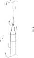
- the guidewire 100includes a distal end 102 and a proximal end 104, as illustrated for example, in FIG. 2 .
- the guidewire 100may include a transition region 106 disposed between the proximal end 104 and the distal end 102, the transition region 106 providing a transition in stiffness/flexibility characteristics of the guidewire 100 along the length thereof.
- the guidewire 100may include one or more tapers and/or tapered regions, one or more constant diameter sections, and/or may generally include a constant inner and outer diameter. The tapers and/or constant diameters may be manifested in variations and/or consistencies in the size of the outer diameter, inner diameter, and/or wall thickness of the guidewire 100.
- the constant diameter sectionsmay be the same diameter or different diameters.
- a proximal section 110may have a first generally constant diameter and a distal section 120 may have a second generally constant diameter.
- the second diametermay be less than the first diameter.
- the first diametermay be less than the second diameter.
- the first diameter and the second diametermay be substantially equal.
- the proximal section 110 and/or the distal section 120may be tapered and/or have a varying diameter.
- a tapered transition region 106may be disposed between the proximal section 110 and the distal section 120, as seen in FIG. 2 .
- the tapered transition region 106may taper distally from the first diameter to the second diameter.
- Tapered transition region(s) 106may be linearly tapered, tapered in a curvilinear fashion, uniformly tapered, non-uniformly tapered, or tapered in a step-wise fashion. The angle of any such tapers can vary, depending upon the desired flexibility characteristics.
- the length of the tapermay be selected to obtain a more (longer length) or less (shorter length) gradual transition in stiffness/flexibility characteristics.
- any portion of the guidewire 100may be tapered or can have a constant diameter, and that any tapers and/or constant diameter can extend in either the proximal or the distal direction, for example, to achieve the desired flexibility, stiffness, and/or torque transmission characteristics.
- the guidewire 100may have one or more lumens having an inner diameter that is in the range of about 0,2032 mm [0.008 inch] to about 0,762 mm [0.030 inch] in size, and in some embodiments, in the range of about 0,381 mm [0.015 inch] to about 0,635 mm [0.025 inch] in size.
- the guidewire 100may have a maximum or first outer diameter that is in the range of about 0,254 mm [0.010 inch] to about 1,27 mm [0.050 inch] in size, and in some embodiments, in the range of about 0,508 mm [0.020 inch] to about 1,016 mm [0.040 inch] in size, and in some embodiments, about 0,889 mm [0.035 inch]. It should be understood however, that these and other dimensions provided herein are by way of example embodiments only, and that in other embodiments, the size of the inner and outer diameter of the guidewire 100 can vary greatly from the dimensions given, depending upon the desired characteristics and function of the device.
- An outer profile of the guidewire 100may be formed by any one of a number of different techniques, for example, by centerless grinding methods, stamping methods, extrusion methods, coextrusion methods, and the like.
- a centerless grinding techniquemay utilize an indexing system employing sensors (e.g., optical/reflective, magnetic) to avoid excessive grinding.
- the centerless grinding techniquemay utilize a CBN or diamond abrasive grinding wheel that is well shaped and dressed to avoid grabbing the guidewire 100 during the grinding process.
- centerless grindingcan be achieved using a Royal Master HI-AC centerless grinder.
- the guidewire 100may also include structure or otherwise be adapted and/or configured to achieve a desired level of stiffness, torqueability, flexibility, and/or other characteristics.
- the desired stiffness, torqueability, lateral flexibility, bendability or other such characteristics of the guidewire 100can be imparted, enhanced, or modified by the particular structure that may be used or incorporated into the guidewire 100.
- the flexibility of the guidewire 100can vary along its length, for example, such that the flexibility can be higher at the distal end 102 relative to the proximal end 104, or vice versa.
- the distal section 120is more flexible than the proximal section 110.
- the guidewire 100can have a substantially constant flexibility along the entire length thereof.
- the distal section 120may be pre-shaped to form a distal loop disposed distally of the tapered region 106 within the distal section 120.
- a guidewiremay include a thin wall tubular structure including a plurality of apertures, such as grooves, cuts, slits, slots, or the like, formed in a portion of, or along the entire length of, the guidewire.
- the plurality of aperturesmay be formed such that one or more spines or beams are formed in the guidewire.
- Such spines or beamscould include portions of the guidewire that remain after the plurality of apertures is formed in the thin wall tubular structure of the guidewire, and may act to maintain a relatively high degree of torsional stiffness while maintaining a desired level of lateral flexibility due to the plurality of apertures.
- the plurality of aperturescan be formed in essentially any known way.
- the plurality of aperturescan be formed by methods such as micro-machining, saw-cutting, laser cutting, grinding, milling, casting, molding, chemically etching or treating, or other known methods, and the like.
- the structure of the guidewireis formed by cutting and/or removing portions of the thin wall tubular structure to form the plurality of apertures.
- the plurality of aperturescan completely penetrate an outer wall of the guidewire such that there is fluid communication between a lumen extending therethrough (i.e., defined by the outer wall) and an exterior of the guidewire through the plurality of apertures.
- the shape and size of the plurality of aperturescan vary, for example, to achieve the desired characteristics.
- the shape of the plurality of aperturescan vary to include essentially any appropriate shape, such as squared, round, rectangular, pill-shaped, oval, polygonal, elongated, irregular, spiral (which may or may not vary in pitch), or other suitable means or the like, and may include rounded or squared edges, and can be variable in length and width, and the like.
- a guidewiremay include a helical coil having adjacent turns spaced apart to form a plurality of apertures extending through to an interior lumen. Other configurations, arrangements, and/or combinations thereof may also be used.
- some adjacent aperturescan be formed such that they include portions that overlap with each other about the circumference of the guidewire. In other embodiments, some adjacent apertures can be disposed such that they do not necessarily overlap with each other, but are disposed in a pattern that provides the desired degree of lateral flexibility. Additionally, the apertures can be arranged along the length of, or about the circumference of, the guidewire to achieve desired properties. For example, the apertures can be arranged in a symmetrical pattern, such as being disposed essentially equally on opposite sides about the circumference of the guidewire, or equally spaced along the length of the guidewire, or can be arranged in an increasing or decreasing density pattern, or can be arranged in a non-symmetric or irregular pattern.
- the spacing, arrangement, and/or orientation of the plurality of apertures, or in the associated spines or beams that may be formedcan be varied to achieve the desired characteristics.
- the number, proximity (to one another), density, size, shape, and/or depth of the plurality of apertures along the length of the guidewiremay vary in either a stepwise fashion or consistently, depending upon the desired characteristics.
- the quantity or proximity of the plurality of apertures to one another near one end of the guidewiremay be high, while the quantity or proximity of the plurality of apertures to one another near the other end of the guidewire, may be relatively low, or vice versa.
- a distal region of the guidewiremay include a greater density of apertures, while a proximal region of the guidewire may include a lesser density of apertures, or may even be devoid of any apertures.
- the distal regionmay have a greater degree of lateral flexibility relative to the proximal region. It should be understood that similar variations in the size, shape and/or depth of the plurality of apertures along the length of the guidewire can also be used to achieve desired flexibility differences thereof.
- the flexibility characteristics of a guidewirecould also be achieved using other methods, such as by the addition of material and/or one or more reinforcement members to certain portions of the guidewire.
- any of a broad variety of attachment techniques and/or structurescan be used to attachment additional material and/or one or more reinforcement members to a guidewire.
- suitable attachment techniquesinclude welding, soldering, brazing, crimping, friction fitting, adhesive bonding, mechanical interlocking and the like.
- Some examples of welding processes that can be suitable in some embodimentsinclude LASER welding, resistance welding, TIG welding, microplasma welding, electron beam welding, friction welding, inertia welding, or the like.
- LASER welding equipmentwhich may be suitable in some applications is commercially available from Unitek Miyachi of Monrovia, California and Rofin-Sinar Incorporated of Georgia, Michigan. Resistance welding equipment which may be suitable in some applications is commercially available from Palomar Products Incorporated of Carlsbad, California and Polaris Electronics of Olathe, Kansas.
- TIG welding equipment which may be suitable in some applicationsis commercially available from Weldlogic Incorporated of Newbury Park, California.
- Microplasma welding equipmentwhich may be suitable in some applications is commercially available from Process Welding Systems Incorporated of Smyrna, Tennessee.
- LASER or plasma weldingcan be used to achieve the attachment.
- a light beamis used to supply the necessary heat.
- LASER weldingcan be beneficial in the processes contemplated by the invention, as the use of a LASER light heat source can provide significant accuracy. It should also be understood that such LASER welding can also be used to attach other components to the device.
- LASER energycan be used as the heat source for soldering, brazing, or the like for attaching different components or structures of the guidewire together.
- the use of a LASER as a heat source for such connection techniquescan be beneficial, as the use of a LASER light heat source can provide substantial accuracy.
- One particular example of such a techniqueincludes LASER diode soldering.
- attachmentmay be achieved and/or aided through the use of a mechanical connector or body, and/or by an expandable alloy, for example, a bismuth alloy.
- an expandable alloyfor example, a bismuth alloy.
- a coatingfor example a lubricious (i.e., hydrophilic, hydrophobic, etc.) or other type of coating may be applied over portions or all of the guidewire 100 discussed above.
- Hydrophobic coatingssuch as fluoropolymers, silicones, and the like provide a dry lubricity which improves guidewire handling and device exchanges.
- Lubricious coatingsimprove steerability and improve lesion crossing capability.
- Suitable lubricious polymersare well known in the art and may include (but are not limited to) hydrophilic polymers such as polyarylene oxides, polyvinylpyrolidones, polyvinylalcohols, hydroxy alkyl cellulosics, algins, saccharides, caprolactones, and the like, and mixtures and combinations thereof. Hydrophilic polymers may be blended among themselves or with formulated amounts of water insoluble compounds (including some polymers) to yield coatings with suitable lubricity, bonding, and solubility. Some other examples of such coatings and materials and methods used to create such coatings can be found in U.S. Patent Nos. 6,139,510 and 5,772,609 . In some embodiments, a more distal portion of a guidewire is coated with a hydrophilic polymer, and a more proximal portion is coated with a fluoropolymer, such as polytetrafluroethylene (PTFE).
- PTFEpolytetrafluroethylene
- coating layerin some embodiments can impart a desired flexibility to the guidewire.
- Choice of coating materialsmay vary, depending upon the desired characteristics. For example, coatings with a low durometer or hardness may have very little effect on the overall flexibility of the guidewire. Conversely, coatings with a high durometer may make for a stiffer and/or less flexible shaft.
- a distal end 102 of the guidewire 100may be advanced percutaneously upstream within a patient's aorta 10 to a treatment site (i.e., a patient's heart 20 and/or an aortic valve 22).
- the distal end 102may be advanced through the treatment site (i.e., the patient's aortic valve 22) into a patient's left ventricle 24.
- the distal section 120may curl within the left ventricle 24 and/or make contact with an apex 26 of the left ventricle, as seen in FIG. 1 .
- the distal section 120may be flexible enough to bend and/or curl within the left ventricle 24 so as to form a distal loop.
- proximal section 110is stiffer than the distal section 120 and may resist bending.
- contact within the apex 26may result in a kink 108 forming within or adjacent to the distal section 120, as illustrated for example, in FIG.'s 3 and 4.
- the kink 108may undesirably perforate a wall of the left ventricle 24, for example at or near the apex 26.
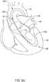
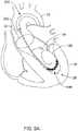
- FIG. 5Aillustratively shows a typical positioning of the guidewire 100 within the aorta 10 and the left ventricle 24 during a TAVI procedure.
- a suitable TAVI device 200may be disposed on and/or advanced distally over the guidewire 100.
- the TAVI device 200may end in a position illustrated in FIG. 5B , wherein a portion of the TAVI device 200 (i.e., nosecone 202, for example, which may be attached to an inner shaft 204 in some embodiments) may follow the guidewire 100 past the apex 26.
- the nosecone 202may be advanced far enough into the left ventricle 24 to provide adequate clearance for deployment and/or expansion of a replacement heart valve member.
- the TAVI device 200may end in a position illustrated in FIG. 5B , wherein a portion of the TAVI device 200 (i.e., nosecone 202, for example) may track the guidewire 100 past the apex 26. This may happen, for example, in instances where the patient being treated has a small left ventricle.
- a portion of the TAVI device 200i.e., nosecone 202, for example
- movement of the TAVI device 200 over the guidewire 100 and/or deployment of the replacement heart valve member 210may result in the stiffer proximal section 110 of the guidewire 100 perforating a wall of the left ventricle 24 due to friction (i.e., a "sawing" effect, for example), excessive pressure placed on the wall of the ventricle 24, abrasion by passage of the nosecone 202, or for other reasons.
- FIG. 6schematically illustrates an expandable protection element 140 disposed on, over, or about the guidewire 100 in a collapsed configuration.
- the expandable protection element 140may extend from or over at least a portion of the proximal section 110, across the tapered region 106, and onto or over at least a portion of the distal section 120.
- the guidewire 100may extend through the expandable protection element 140.
- the expandable protection element 140may be disposed alongside or adjacent to the guidewire 100.
- the expandable protection element 140may be disposed at a position along a length of the guidewire 100 most likely to form or develop kink 108 and/or to be located at or within the apex 26.
- the expandable protection element 140may be designed and/or configured to be placed within the apex 26. In some embodiments, the expandable protection element 140 may be located within the apex 26 through normal operation of the guidewire 100 and/or the TAVI device 200.
- the expandable protection element 140may include an inflatable balloon 340, as seen for example in FIG.'s 7 and 8, and/or other suitable soft feature.
- a suitable soft featuremay include an expandable sponge, foam, or soft rubbery material, for example.
- the inflatable balloon 340 or other suitable soft featurein an expanded configuration, may include a generally wide, flat cross-section thereby providing a large surface area to contact the wall of the left ventricle 24 and/or the apex 26.
- at least a portion of the proximal section 110 of the guidewire 100may include an inflation lumen extending therethrough to an inflation port 342 opening into the inflatable balloon 340, as may be seen in FIG. 7 .
- the inflation port 342may be disposed at or adjacent to a distal end of the proximal section 110.
- the inflation port 342may be disposed within the tapered region 106.
- the inflatable balloon 340may include a thin middle section extending along a longitudinal length of the inflatable balloon 340, as seen for example in FIG. 7A , for easier insertion and withdrawal through a guide catheter or delivery system.
- the thin middle sectionmay provide enhanced folding characteristics.
- a proximal waist of the inflatable balloon 340may be fixedly attached to the proximal section 110 of the guidewire 100, and a distal waist of the inflatable balloon 340 may be fixedly attached to the distal section 120 of the guidewire 100.
- the large surface area of the inflatable balloon 340may spread force(s) applied to the guidewire 100 out over a larger area of a wall of the left ventricle 24 and prevent a kink 108 from perforating a wall of the left ventricle 24 and/or the apex 26.
- the skilled artisanwill readily recognize that when the guidewire 100 illustrated in FIG.8 is positioned as shown in FIG.
- the inflatable balloon 340 or other suitable soft featuremay prevent a kink 108 from perforating a wall of the left ventricle 24 and/or the apex 26 by substantially increasing the surface area of the expandable element thereby reducing and/or eliminating puncture pressure (i.e., force per area), and/or protecting any sharp point, tip, or apex along a length of the guidewire 100 that may contact and/or penetrate the adjacent tissue (i.e., the wall of the left ventricle 24 and/or the apex 26).
- puncture pressurei.e., force per area
- a shape of the balloon 340 or other suitable soft featuremay maintain the guidewire 100 and/or kink 108 in a spaced-apart relationship with the wall of the left ventricle 24, wherein only the inflatable balloon 340 or other suitable soft feature contacts the apex 26.
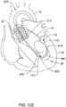
- FIG. 9Aschematically illustrates an expandable element 440 fixedly attached to the guidewire 100 at or adjacent to the tapered region 106 in an expanded configuration, and disposed within the left ventricle 24 bridging or extending over the apex 26.
- the expandable element 440may be a stent-like structure, an expandable frame or cage, or other suitable element.
- the expandable element 440may be self-expanding.
- the expandable element 440may be actuated between the collapsed configuration and the expanded configuration by a pull wire, a suture, a release element, or other actuation element.
- a proximal end of the expandable element 440may include a tapered structure extending distally and/or radially outwardly from the proximal section 110 of the guidewire 100.
- the expandable element 440may extend longitudinally along the guidewire 100 and/or the expandable element 440 may maintain the guidewire 100 and/or kink 108 in a spaced-apart relationship with the wall of the left ventricle 24. In some embodiments, only the expandable element 440 contacts the apex 26.
- a distal nosecone 202may engage the proximal end of the expandable element 440. Further advancement of the TAVI device 200 may advance the nosecone 202 and the inner shaft 204 over the expandable element 440, which may gradually collapse toward the collapsed configuration as the nosecone 202 and/or the inner shaft 204 is advanced distally over the expandable element 440, as seen in FIG. 9B .
- FIG. 10schematically illustrates an example guidewire 500 having an expandable element 540 disposed on the guidewire 500 in an expanded configuration, and disposed within the apex 26 of the left ventricle 24.
- the guidewire 500may extend into and/or through the expandable protection element 540.
- the expandable element 540may be disposed at the distal end of the guidewire 500.
- the expandable element 540may include a rounded, irregularly-shaped, and/or ball-shaped balloon or other suitable soft feature.
- a suitable soft featuremay include an expandable sponge, foam, or soft rubbery material, for example.
- the expandable element 540in an expanded configuration, may include a shape that enables the expandable element 540 to engage and/or interact with the apex 26 such that the distal end of the guidewire may be anchored in the apex 26.
- at least a portion of the proximal section 510 and/or the distal section 520 of the guidewire 500may include an inflation lumen extending therethrough to an inflation port.
- the inflation portmay be disposed at or adjacent to the distal end of the guidewire 500.
- the guidewire 500may have substantially the same construction and/or characteristics as the guidewire 100 discussed above.
- the guidewire 500may be pre-shaped to generally position the guidewire 500 off of (i.e., in a spaced-apart relationship with) the wall of the left ventricle 24. Such positioning may prevent the nosecone 202 from damaging the wall of the left ventricle 24 and/or from pushing into or damaging the apex 26. Since the guidewire 500 is generally anchored in place suspended within the left ventricle 24, movement of a TAVI device 200 would be prevented from causing the guidewire 500 to perforate the wall of the left ventricle 24.
- FIG. 11Aschematically illustrates a guidewire 600 disposed within an aorta 10, and/or an aortic valve 22 and a left ventricle 24 of a heart 20.
- Treatment of an aortic valve 22 using a TAVI devicemay sometimes involve insertion of a relatively stiff guidewire 600, which may or may not have a relatively flexible distal tip, upstream through the aorta 10 and/or the aortic valve 22 into the left ventricle 24.
- a suitable TAVI devicemay be inserted and/or advanced over the guidewire 600 to the heart 20 and/or the aortic valve 22. As shown in FIG.
- the guidewire 600may extend upstream through the aorta 10, across or through the aortic arch, and through the aortic valve 22 into the left ventricle 24 of a patient's heart 20.
- a distal end of the guidewire 600may be positioned within the left ventricle 24 during a TAVI procedure.
- the guidewire 600may have substantially the same construction and/or characteristics as the guidewire 100 discussed above.
- a distal end of the guidewire 600may be advanced percutaneously upstream within a patient's aorta 10 to a treatment site (i.e., a patient's heart 20 and/or an aortic valve 22).
- the distal endmay be advanced through the treatment site (i.e., the patient's aortic valve 22) into a patient's left ventricle 24.
- the distal section 620may curl within the left ventricle 24 and/or make contact with an apex 26 of the left ventricle, as seen in FIG. 11A .
- the distal section 620may be of sufficient length and flexibility to bend and/or curl within the left ventricle 24 so as to form more than one distal loop.
- the distal section 620 of the guidewire 600may include at least two distal curves 660 traversing the apex 26 and at least one proximal curve disposed therebetween. Each of the distal curves 660 may be in contact with the wall(s) of the left ventricle 24.
- force(s) applied to the guidewire 600may be spread out to a greater area of the wall(s) of the left ventricle 24. Additionally, more than one distal loop may increase available counter-traction, thereby making it harder to accidentally pull or remove the guidewire 600 when advancing a TAVI device or other medical device thereover.
- FIG. 11Bschematically illustrates a guidewire 700 disposed within an aorta 10, and/or an aortic valve 22 and a left ventricle 24 of a heart 20.
- Treatment of an aortic valve 22 using a TAVI devicemay sometimes involve insertion of a relatively stiff guidewire 700, which may or may not have a relatively flexible distal tip, upstream through the aorta 10 and/or the aortic valve 22 into the left ventricle 24.
- a suitable TAVI device 200may be inserted and/or advanced over the guidewire 700 to the heart 20 and/or the aortic valve 22. As shown in FIG.
- the guidewire 700may extend upstream through the aorta 10, across or through the aortic arch, and through the aortic valve 22 into the left ventricle 24 of a patient's heart 20.
- a distal end of the guidewire 700may be positioned within the left ventricle 24 during a TAVI procedure.
- the guidewire 700may have substantially the same construction and/or characteristics as the guidewire 100 discussed above.
- a distal end of the guidewire 700may be advanced percutaneously upstream within a patient's aorta 10 to a treatment site (i.e., a patient's heart 20 and/or an aortic valve 22).
- the distal endmay be advanced through the treatment site (i.e., the patient's aortic valve 22) into a patient's left ventricle 24.
- the distal section of the guidewire 700may curl within the left ventricle 24 and/or make contact with an apex 26 of the left ventricle, as seen in FIG. 11B .
- the distal section of the guidewire 700may be of sufficient length and flexibility to bend and/or curl within the left ventricle 24 so as to form more than one distal loop.
- the distal section of the guidewire 700may be pre-shaped to generally position at least a portion of the guidewire 700 off of (i.e., in a spaced-apart relationship with) the wall of the left ventricle 24.
- a proximally-disposed distal loop, relative to a length of the guidewire 700may be suspended off of the wall(s) of the left ventricle 24, such that only a more distally-disposed distal loop, relative to the length of the guidewire 700, contacts the wall(s) of the left ventricle 24.
- Such a configurationmay prevent the nosecone 202 from damaging the wall of the left ventricle 24 and/or from pushing into or damaging the apex 26 as the nosecone 202 and/or the TAVI device 200 is advanced distally and/or deployed.
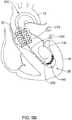
- FIG. 12Aschematically illustrates an expandable element 840 slidably disposed about an example guidewire 100 in an expanded configuration at a first position.
- the expandable element 840may include an inflatable balloon and/or other suitable soft feature.
- a suitable soft featuremay include an expandable sponge, foam, or soft rubbery material, for example.
- the inflatable balloon or other suitable soft featurein an expanded configuration, may include a generally wide, flat cross-section thereby providing a large surface area to contact the wall of the left ventricle 24 and/or the apex 26.
- at least a portion of the proximal section 110 of the guidewire 100may include an inflation lumen extending therethrough to an inflation port 842.
- the inflation port 842may be disposed at or adjacent to a distal end of the proximal section 110.
- the inflation port 842may be disposed within the tapered region 106.
- the inflatable balloonmay include a thin middle section extending along a longitudinal length of the inflatable balloon for easier insertion and withdrawal through a guide catheter or delivery system.
- the thin middle sectionmay provide enhanced folding characteristics.
- a proximal waist of the inflatable balloonmay be slidably attached to the proximal section 110 of the guidewire 100, and a distal waist of the inflatable balloon may be slidably attached to the distal section 120 of the guidewire 100.
- Each of the proximal waist and the distal waistmay include a sealing feature configured to maintain inflation fluid within an interior of the inflatable balloon while permitting the inflatable balloon to slide axially along the guidewire 100.
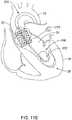
- a distal stop 870such as a ring, a protrusion, or other suitable feature, may be disposed on or formed as a part of the distal section 120 of the guidewire 100, wherein the distal stop 870 arrests distal translation of inflatable balloon at a second position, as seen in FIG. 12B .
- the inflation port 842may be maintained within an interior of the inflatable balloon (i.e., disposed between the proximal waist and the distal waist) in both the first position and the second position in order to maintain and/or adjust inflation fluid pressure within the inflatable balloon at any time during the procedure.
- the nosecone 202may come into contact with the expandable element 840.
- the expandable element 840may slide axially in a distal direction as the nosecone 202 is advanced until the expandable element contacts the distal stop 870.
- the large surface area of the inflatable balloonmay spread force(s) applied to the guidewire 100 out over a larger area of a wall of the left ventricle 24 and prevent a kink 108 from perforating a wall of the left ventricle 24 and/or the apex 26.
- the skilled artisanwill readily recognize that when the guidewire 100 illustrated in FIG.12B is positioned as shown in FIG.
- the inflatable balloon or other suitable soft featuremay prevent a kink 108 from perforating a wall of the left ventricle 24 and/or the apex 26 by substantially increasing the surface area of the expandable element thereby reducing and/or eliminating puncture pressure (i.e., force per area), and/or protecting any sharp point, tip, or apex along a length of the guidewire 100 that may contact and/or penetrate the adjacent tissue (i.e., the wall of the left ventricle 24 and/or the apex 26).
- puncture pressurei.e., force per area
- a shape of the inflatable balloon or other suitable soft featuremay maintain the guidewire 100 and/or kink 108 in a spaced-apart relationship with the wall of the left ventricle 24, wherein only the inflatable balloon or other suitable soft feature contacts the apex 26.
- a method of protecting an apex of a left ventricle of a heart of a patient during a TAVI proceduremay include:
- each of the guidewires described abovemay include and/or be used with a wire holder configured to fixedly mount the guidewire in place axially during a TAVI procedure.
- a wire holdermay mount using magnetic, mechanical, or other suitable means to an operating or procedure table.
- a suitable mechanism for securing the guidewire to the wire holdermay be used, including but not limited to, friction, mechanical, notching, pinching, extendable feature(s), or other suitable mechanisms.
- additional stress and/or force(s)may be applied to the guidewire, which may lead to axial movement and/or damage and/or perforation of the wall of the left ventricle.
- a practitionermay engage the guidewire with the wire holder, thereby locking the guidewire in place and preventing axial translation of the guidewire relative to the wire holder.
- a method of protecting an apex of a left ventricle of a heart of a patient during a TAVI proceduremay include:
- the distal section of the guidewiremay form one or more distal loops within the left ventricle, wherein positioning the tapered region adjacent the apex further includes positioning the one or more distal loops against a wall of the left ventricle.
- one or both of the steps of advancing the TAVI device distally over the guidewire or performing a TAVI proceduremay include advancing a nosecone of the TAVI device distally onto the one or more distal loops.
- advancing a nosecone of the TAVI device distallymay include at least partially collapsing the expandable element as the nosecone is advanced over the expandable element.
- advancing a nosecone of the TAVI device distallymay translate the expandable element distally along the guidewire until a distal end of the expandable element contacts a distal stop.
- distal advancement of the noseconemay be stopped or prevented by the expandable element.
- expanding the expandable elementmay include releasing a restraining member such that a self-expanding expandable element may be permitted to expand.
- expanding the expandable elementmay include transferring an inflation fluid through an inflation lumen to the expandable element.
- expanding the expandable elementmay include exposing an absorbent sponge or foam to fluid or blood.
- the methodmay include engaging the guidewire with a guidewire holder disposed external to the patient, the guidewire holder being configured to prevent axial movement of the guidewire during the TAVI procedure.
- devices and methods in accordance with the inventioncan be adapted and configured for use in other parts of the anatomy of a patient.
- devices and methods in accordance with the inventioncan be adapted for use in the digestive or gastrointestinal tract, such as in the mouth, throat, small and large intestine, colon, rectum, and the like.
- devices and methodscan be adapted and configured for use within the respiratory tract, such as in the mouth, nose, throat, bronchial passages, nasal passages, lungs, and the like.
- the medical devices described herein with respect to percutaneous deploymentmay be used in other types of surgical procedures as appropriate.
- the medical devicesmay be deployed in a non-percutaneous procedure, including an open heart procedure.
- Devices and methods in accordance with the inventioncan also be adapted and configured for other uses within the anatomy.
Landscapes
- Health & Medical Sciences (AREA)
- Life Sciences & Earth Sciences (AREA)
- Veterinary Medicine (AREA)
- Animal Behavior & Ethology (AREA)
- Engineering & Computer Science (AREA)
- Public Health (AREA)
- Biomedical Technology (AREA)
- Heart & Thoracic Surgery (AREA)
- General Health & Medical Sciences (AREA)
- Cardiology (AREA)
- Pulmonology (AREA)
- Hematology (AREA)
- Anesthesiology (AREA)
- Biophysics (AREA)
- Oral & Maxillofacial Surgery (AREA)
- Transplantation (AREA)
- Vascular Medicine (AREA)
- Prostheses (AREA)
Description
- The disclosure relates generally to medical devices and more particularly to medical devices that are adapted for use in procedures for repairing heart valves.
- Aortic valve stenosis is a frequent expression of valvular heart disease, and may often be a leading indicator for valve replacement therapy in Europe and the United States. The prevalence of aortic valve stenosis tends to increase in older population groups. In some cases, traditional open-heart valve replacement surgery is not suitable for patients with higher surgical risk factors. Alternate therapies, and/or linking therapies that may transition an at-risk patient to a more suitable condition for traditional open-heart valve replacement surgery, may be beneficial in improving the lifestyle of patients suffering from aortic valve stenosis.
US 2013/0158655 discloses a medical device handle including a handle housing, a rotatable collar, a rotatable control knob and a slidable door disposed about the collar.US 2003/163156 A1 discloses a guidewire comprising an expandable balloon, which is used to open a stenosed vessel. A continuing need exists for improved devices and methods for use in alternative or predecessor treatments to traditional open-heart valve replacement surgery.- The present invention pertains to a guidewire system as set forth in the claims. The guidewire system includes a guidewire having a proximal end, a distal end, and a length extending therebetween, wherein the guidewire includes a relatively stiff proximal section and a relatively flexible distal section joined by a transition region, and a TAVI device slidably disposed on the guidewire, wherein the guidewire includes an expandable element disposed about the transition region in a first position, wherein the expandable element is configured to expand from a collapsed configuration to an expanded configuration.
- Although discussed with specific reference to use within the coronary vasculature of a patient, for example to repair a heart valve, medical devices and methods of use in accordance with the disclosure can be adapted and configured for use in other parts of the anatomy, such as the digestive system, the respiratory system, or other parts of the anatomy of a patient.
FIG. 1 is a schematic partial view of an aortic heart valve having an example guidewire system disposed therein;FIG. 2 is a side view of an example guidewire system;FIG. 3 is a side view of an example guidewire system;FIG. 4 is a schematic partial view of an aortic heart valve having an example guidewire system disposed therein;FIG. 5A is a schematic partial view of an example TAVI device disposed on an example guidewire system disposed within an aortic heart valve;FIG. 5B is a schematic partial view of the example TAVI device ofFIG. 5A expanded within the aortic heart valve;FIG. 6 is a side view of an example guidewire system;FIG. 7 is a side view of an example guidewire system;FIG. 7A is an end view of the example guidewire system ofFIG. 7 ;FIG. 8 is a side view of an example guidewire system;FIG. 9A is a schematic partial view of an example guidewire system disposed within an aortic heart valve;FIG. 9B is a schematic partial view of the example guidewire system ofFIG. 9A with an example TAVI device partially advanced thereover;FIG. 10 is a schematic partial view of an example guidewire system;FIG. 11A is a schematic partial view of an example guidewire system;FIG. 11B is a schematic partial view of an example guidewire system with a portion of an example TAVI device disposed thereon;FIG. 12A is a schematic partial view of an example guidewire system with an example TAVI device disposed thereon; andFIG. 12B is a schematic partial view of the example guidewire system ofFIG. 12A with an example TAVI device disposed thereon.- While the invention is amenable to various modifications and alternative forms, specifics thereof have been shown by way of example in the drawings and will be described in greater detail below. It should be understood, however, that the intention is not to limit the invention to the particular embodiments described.
- The following description should be read with reference to the drawings, which are not necessarily to scale, wherein like reference numerals indicate like elements throughout the several views. One of ordinary skill in the art will readily appreciate and understand that a particular element or feature from any disclosed or illustrated example embodiment herein may be incorporated into any other example embodiment unless expressly stated otherwise. The detailed description and drawings are intended to illustrate but not limit the claimed invention.
- For the following defined terms, these definitions shall be applied, unless a different definition is given in the claims or elsewhere in this specification.
- The terms "upstream" and "downstream" refer to a position or location relative to the direction of blood flow through a particular element or location, such as a vessel (i.e., the aorta), a heart valve (i.e., the aortic valve), and the like.
- All numeric values are herein assumed to be modified by the term "about," whether or not explicitly indicated. The term "about", in the context of numeric values, generally refers to a range of numbers that one of skill in the art would consider equivalent to the recited value (i.e., having the same function or result). In many instances, the term "about" may include numbers that are rounded to the nearest significant figure. Other uses of the term "about" (i.e., in a context other than numeric values) may be assumed to have their ordinary and customary definition(s), as understood from and consistent with the context of the specification, unless otherwise specified.
- Weight percent, percent by weight, wt%, wt-%, % by weight, and the like are synonyms that refer to the concentration of a substance as the weight of that substance divided by the weight of the composition and multiplied by 100.
- The recitation of numerical ranges by endpoints includes all numbers within that range (e.g. 1 to 5 includes 1, 1.5, 2, 2.75, 3, 3.80, 4, and 5).
- As used in this specification and the appended claims, the singular forms "a", "an", and "the" include plural referents unless the content clearly dictates otherwise. As used in this specification and the appended claims, the term "or" is generally employed in its sense including "and/or" unless the content clearly dictates otherwise.
- It is noted that references in the specification to "an embodiment", "some embodiments", "other embodiments", etc., indicate that the embodiment(s) described may include a particular feature, structure, or characteristic, but every embodiment may not necessarily include the particular feature, structure, or characteristic. Moreover, such phrases are not necessarily referring to the same embodiment. Further, when a particular feature, structure, or characteristic is described in connection with an embodiment, it would be within the knowledge of one skilled in the art to effect such feature, structure, or characteristic in connection with other embodiments, whether or not explicitly described, unless clearly stated to the contrary. That is, the various individual elements described below, even if not explicitly shown in a particular combination, are nevertheless contemplated as being combinable or arrangable with each other to form other additional embodiments or to complement and/or enrich the described embodiment(s), as would be understood by one of ordinary skill in the art.
- Diseases and/or medical conditions that impact the cardiovascular system are prevalent in the United States and throughout the world. Traditionally, treatment of the cardiovascular system was often conducted by directly accessing the impacted part of the system. For example, treatment of a blockage in one or more of the coronary arteries was traditionally treated using coronary artery bypass surgery. As can be readily appreciated, such therapies are rather invasive to the patient and require significant recovery times and/or treatments. More recently, less invasive therapies have been developed, for example, where a blocked coronary artery could be accessed and treated via a percutaneous catheter (e.g., angioplasty). Such therapies have gained wide acceptance among patients and clinicians.
- Some relatively common medical conditions may include or be the result of inefficiency, ineffectiveness, or complete failure of one or more of the valves within the heart. For example, failure of the aortic valve can have a serious effect on a human and could lead to a serious health condition and/or death if not dealt with. A human heart includes several different heart valves, including aortic, pulmonary, mitral, and tricuspid valves, which control the flow of blood to and from the heart. Over time, a heart valve may become obstructed, narrowed, and/or less flexible (i.e., stenosed) due to hardening, calcium deposition, or other factors, thereby reducing the flow of blood through the valve and/or increasing the pressure within the chambers of the heart as the heart attempts to pump the blood through the vasculature. One traditional treatment method is valve replacement, where the stenosed valve is removed and a replacement tissue or mechanical valve is implanted via open heart surgery. Alternative treatments, including percutaneous valve replacement procedures (i.e., transcatheter aortic valve implantation, or TAVI) which may deliver and implant a replacement heart valve (i.e., aortic valve), have been developed which may be much less invasive to the patient. The devices and methods described herein may provide additional desirable features and benefits for use in such procedures.
- A typical aortic valve may comprise three leaflets, although two leaflet and four leaflet valves are known to occur in a portion of the population. For simplicity, the following discussion will be described in the context of treating a typical aortic valve. However, it is fully contemplated that the devices and methods described herein may be adapted for use in the treatment of a two or four (or more) leaflet heart valve and/or a non-aortic heart valve. One of ordinary skill in the art will understand that in the event of treating a non-aortic heart valve, the relative orientations and directions associated with the described devices and methods may be modified to accommodate the specifics (i.e., orientation, location, size, etc.) of the heart valve undergoing treatment.
FIG. 1 schematically illustrates aguidewire 100 disposed within anaorta 10, and/or anaortic valve 22 and aleft ventricle 24 of aheart 20. Treatment of anaortic valve 22 using a TAVI device may sometimes involve insertion of a relativelystiff guidewire 100, which may or may not have a relatively flexible distal tip, upstream through theaorta 10 and/or theaortic valve 22 into theleft ventricle 24. Later, a suitable TAVI device may be inserted and/or advanced over theguidewire 100 to theheart 20 and/or theaortic valve 22. As shown inFIG. 1 , theguidewire 100 may extend upstream through theaorta 10, across or through the aortic arch, and through theaortic valve 22 into theleft ventricle 24 of a patient'sheart 20. In some embodiments, adistal end 102 of theguidewire 100 may be positioned within theleft ventricle 24 during a TAVI procedure.- In some embodiments, the
guidewire 100 may have a substantially solid cross-section. In some embodiments, theguidewire 100 may be tubular or hollow in construction, with one or more lumens disposed therein, such as, for example, a hypotube or a thin-walled tubular catheter. Those of skill in the art and others will recognize that the materials, structures, and dimensions of theguidewire 100 are dictated primarily by the desired characteristics and function of the final guidewire, and that any of a broad range of materials, structures, and dimensions can be used. - For example, the
guidewire 100 may be formed of any materials suitable for use, dependent upon the desired properties of theguidewire 100. Some examples of suitable materials include metals, metal alloys, polymers, composites, or the like, or combinations or mixtures thereof. Some examples of suitable metals and metal alloys include stainless steel, such as 304V, 304L, and 316L stainless steel; alloys including nickel-titanium alloy such as linear elastic or superelastic (i.e., pseudoelastic) nitinol; nickel-chromium alloy; nickel-chromium-iron alloy; cobalt alloy; tungsten or tungsten alloys; MP35-N (having a composition of about 35% Ni, 35% Co, 20% Cr, 9.75% Mo, a maximum 1% Fe, a maximum 1% Ti, a maximum 0.25% C, a maximum 0.15% Mn, and a maximum 0.15% Si); hastelloy; monel 400; inconel 625; or the like; or other suitable material, or combinations or alloys thereof. In some embodiments, it is desirable to use metals or metal alloys that are suitable for metal joining techniques such as welding, soldering, brazing, crimping, friction fitting, adhesive bonding, etc. The particular material used can also be chosen in part based on the desired flexibility requirements or other desired characteristics. - The word nitinol was coined by a group of researchers at the United States Naval Ordinance Laboratory (NOL) who were the first to observe the shape memory behavior of this material. The word nitinol is an acronym including the chemical symbol for nickel (Ni), the chemical symbol for titanium (Ti), and an acronym identifying the Naval Ordinance Laboratory (NOL).
- Within the family of commercially available nitinol alloys is a category designated "linear elastic" which, although similar in chemistry to conventional shape memory and superelastic (i.e., pseudoelastic) varieties, exhibits distinct and useful mechanical properties. By skilled applications of cold work, directional stress and heat treatment, the wire is fabricated in such a way that it does not display a substantial "superelastic plateau" or "flag region" in its stress/strain curve. Instead, as recoverable strain increases, the stress continues to increase in an essentially linear relationship until plastic deformation begins. In some embodiments, the linear elastic nickel-titanium alloy is an alloy that does not show any martensite/austenite phase changes that are detectable by DSC and DMTA analysis over a large temperature range.
- For example, in some embodiments, there are no martensite/austenite phase changes detectable by DSC and DMTA analysis in the range of about -60°C to about 120°C. The mechanical bending properties of such a material are therefore generally inert to the effect of temperature over this very broad range of temperatures. In some particular embodiments, the mechanical properties of the alloy at ambient or room temperature are substantially the same as the mechanical properties at body temperature. In some embodiments, the use of the linear elastic nickel-titanium alloy allows the guidewire to exhibit superior "pushability" around tortuous anatomy.
- In some embodiments, the linear elastic nickel-titanium alloy is in the range of about 50 to about 60 weight percent nickel, with the remainder being essentially titanium. In some particular embodiments, the composition is in the range of about 54 to about 57 weight percent nickel. One example of a suitable nickel-titanium alloy is FHP-NT alloy commercially available from Furukawa Techno Material Co. of Kanagawa, Japan. Some examples of suitable nickel-titanium alloys include those disclosed in
U.S. Patent Nos. 5,238,004 and6,508,803 . In some other embodiments, a superelastic alloy, for example a superelastic nitinol, can be used to achieve desired properties. - Portions or all of the
guidewire 100, or other structures (i.e., markers, for example) included within theguidewire 100, may in some cases be doped with, coated or plated with, made of, or otherwise include a radiopaque material. Radiopaque materials are understood to be materials capable of producing a relatively bright image on a fluoroscopy screen or another imaging technique during a medical procedure. This relatively bright image aids the user of theguidewire 100 in determining its location. Some examples of radiopaque materials can include, but are not limited to, gold, platinum, palladium, tantalum, tungsten alloy, polymer material loaded with a radiopaque filler, and the like, or combinations or alloys thereof. - Additionally, in some instances a degree of MRI compatibility can be imparted into the
guidewire 100. For example, to enhance compatibility with Magnetic Resonance Imaging (MRI) machines, theguidewire 100, or other portions of theguidewire 100, can be made in a manner that would impart a degree of MRI compatibility. For example, theguidewire 100, or portions thereof, may be made of a material that does not substantially distort the image and create substantial artifacts (artifacts are gaps in the image) during MRI imaging. Certain ferromagnetic materials, for example, may not be suitable because they may create artifacts in an MRI image. Theguidewire 100, or portions thereof, may also be made from a material that the MRI machine can image. Some materials that exhibit these characteristics include, for example, tungsten, Elgiloy™, MP35N, nitinol, and the like, and others, or combinations or alloys thereof. - A particular cross-sectional shape of the
guidewire 100 can be any desired shape, for example rounded, oval, rectangular, square, polygonal, and the like, or other such various cross-sectional geometries. The cross-sectional geometries along the length of theguidewire 100 can be constant or can vary. For example, the figures depict theguidewire 100 as having a generally constant round cross-sectional shape, but it can be appreciated that other cross-sectional shapes or combinations of shapes, while not expressly illustrated, may be utilized without departing from the spirit of the invention. - The
guidewire 100 includes adistal end 102 and aproximal end 104, as illustrated for example, inFIG. 2 . In some embodiments, theguidewire 100 may include atransition region 106 disposed between theproximal end 104 and thedistal end 102, thetransition region 106 providing a transition in stiffness/flexibility characteristics of theguidewire 100 along the length thereof. In some embodiments, theguidewire 100 may include one or more tapers and/or tapered regions, one or more constant diameter sections, and/or may generally include a constant inner and outer diameter. The tapers and/or constant diameters may be manifested in variations and/or consistencies in the size of the outer diameter, inner diameter, and/or wall thickness of theguidewire 100. The constant diameter sections may be the same diameter or different diameters. For example, as illustrated inFIG. 2 , aproximal section 110 may have a first generally constant diameter and adistal section 120 may have a second generally constant diameter. In some embodiments, the second diameter may be less than the first diameter. In some embodiments, the first diameter may be less than the second diameter. In some embodiments, the first diameter and the second diameter may be substantially equal. In some embodiments, theproximal section 110 and/or thedistal section 120 may be tapered and/or have a varying diameter. - In some embodiments, a tapered
transition region 106 may be disposed between theproximal section 110 and thedistal section 120, as seen inFIG. 2 . In some embodiments, the taperedtransition region 106 may taper distally from the first diameter to the second diameter. Tapered transition region(s) 106 may be linearly tapered, tapered in a curvilinear fashion, uniformly tapered, non-uniformly tapered, or tapered in a step-wise fashion. The angle of any such tapers can vary, depending upon the desired flexibility characteristics. The length of the taper may be selected to obtain a more (longer length) or less (shorter length) gradual transition in stiffness/flexibility characteristics. It can be appreciated that essentially any portion of theguidewire 100 may be tapered or can have a constant diameter, and that any tapers and/or constant diameter can extend in either the proximal or the distal direction, for example, to achieve the desired flexibility, stiffness, and/or torque transmission characteristics. - In some embodiments, the
guidewire 100 may have one or more lumens having an inner diameter that is in the range of about 0,2032 mm [0.008 inch] to about 0,762 mm [0.030 inch] in size, and in some embodiments, in the range of about 0,381 mm [0.015 inch] to about 0,635 mm [0.025 inch] in size. Additionally, in some embodiments, theguidewire 100 may have a maximum or first outer diameter that is in the range of about 0,254 mm [0.010 inch] to about 1,27 mm [0.050 inch] in size, and in some embodiments, in the range of about 0,508 mm [0.020 inch] to about 1,016 mm [0.040 inch] in size, and in some embodiments, about 0,889 mm [0.035 inch]. It should be understood however, that these and other dimensions provided herein are by way of example embodiments only, and that in other embodiments, the size of the inner and outer diameter of theguidewire 100 can vary greatly from the dimensions given, depending upon the desired characteristics and function of the device. - An outer profile of the
guidewire 100, including any tapered and/or constant diameter portions, may be formed by any one of a number of different techniques, for example, by centerless grinding methods, stamping methods, extrusion methods, coextrusion methods, and the like. A centerless grinding technique may utilize an indexing system employing sensors (e.g., optical/reflective, magnetic) to avoid excessive grinding. In addition, the centerless grinding technique may utilize a CBN or diamond abrasive grinding wheel that is well shaped and dressed to avoid grabbing theguidewire 100 during the grinding process. In some embodiments, centerless grinding can be achieved using a Royal Master HI-AC centerless grinder. Some examples of suitable grinding methods are disclosed inU.S. Patent Application Ser. No. 10/346,698 filed January 17, 2003 U.S. 2004/0142643 ). - The
guidewire 100 may also include structure or otherwise be adapted and/or configured to achieve a desired level of stiffness, torqueability, flexibility, and/or other characteristics. The desired stiffness, torqueability, lateral flexibility, bendability or other such characteristics of theguidewire 100 can be imparted, enhanced, or modified by the particular structure that may be used or incorporated into theguidewire 100. As can thus be appreciated, the flexibility of theguidewire 100 can vary along its length, for example, such that the flexibility can be higher at thedistal end 102 relative to theproximal end 104, or vice versa. According to the invention, thedistal section 120 is more flexible than theproximal section 110. However, in some embodiments not claimed by the present invention, theguidewire 100 can have a substantially constant flexibility along the entire length thereof. In some embodiments, thedistal section 120 may be pre-shaped to form a distal loop disposed distally of the taperedregion 106 within thedistal section 120. - One manner of imparting additional flexibility is to selectively remove material from portions of the guidewire. For example, a guidewire may include a thin wall tubular structure including a plurality of apertures, such as grooves, cuts, slits, slots, or the like, formed in a portion of, or along the entire length of, the guidewire. The plurality of apertures may be formed such that one or more spines or beams are formed in the guidewire. Such spines or beams could include portions of the guidewire that remain after the plurality of apertures is formed in the thin wall tubular structure of the guidewire, and may act to maintain a relatively high degree of torsional stiffness while maintaining a desired level of lateral flexibility due to the plurality of apertures. Such structure may be desirable because it may allow guidewire, or portions thereof, to have a desired level of laterally flexibility as well as have the ability to transmit torque and pushing forces from the proximal end to the distal end. The plurality of apertures can be formed in essentially any known way. For example, the plurality of apertures can be formed by methods such as micro-machining, saw-cutting, laser cutting, grinding, milling, casting, molding, chemically etching or treating, or other known methods, and the like. In some such embodiments, the structure of the guidewire is formed by cutting and/or removing portions of the thin wall tubular structure to form the plurality of apertures.
- In some embodiments, the plurality of apertures can completely penetrate an outer wall of the guidewire such that there is fluid communication between a lumen extending therethrough (i.e., defined by the outer wall) and an exterior of the guidewire through the plurality of apertures. The shape and size of the plurality of apertures can vary, for example, to achieve the desired characteristics. For example, the shape of the plurality of apertures can vary to include essentially any appropriate shape, such as squared, round, rectangular, pill-shaped, oval, polygonal, elongated, irregular, spiral (which may or may not vary in pitch), or other suitable means or the like, and may include rounded or squared edges, and can be variable in length and width, and the like. In some embodiments, a guidewire may include a helical coil having adjacent turns spaced apart to form a plurality of apertures extending through to an interior lumen. Other configurations, arrangements, and/or combinations thereof may also be used.
- In some embodiments, some adjacent apertures can be formed such that they include portions that overlap with each other about the circumference of the guidewire. In other embodiments, some adjacent apertures can be disposed such that they do not necessarily overlap with each other, but are disposed in a pattern that provides the desired degree of lateral flexibility. Additionally, the apertures can be arranged along the length of, or about the circumference of, the guidewire to achieve desired properties. For example, the apertures can be arranged in a symmetrical pattern, such as being disposed essentially equally on opposite sides about the circumference of the guidewire, or equally spaced along the length of the guidewire, or can be arranged in an increasing or decreasing density pattern, or can be arranged in a non-symmetric or irregular pattern.
- As can be appreciated, the spacing, arrangement, and/or orientation of the plurality of apertures, or in the associated spines or beams that may be formed, can be varied to achieve the desired characteristics. For example, the number, proximity (to one another), density, size, shape, and/or depth of the plurality of apertures along the length of the guidewire may vary in either a stepwise fashion or consistently, depending upon the desired characteristics. For example, the quantity or proximity of the plurality of apertures to one another near one end of the guidewire may be high, while the quantity or proximity of the plurality of apertures to one another near the other end of the guidewire, may be relatively low, or vice versa. For example, in the some embodiments, a distal region of the guidewire may include a greater density of apertures, while a proximal region of the guidewire may include a lesser density of apertures, or may even be devoid of any apertures. As such, the distal region may have a greater degree of lateral flexibility relative to the proximal region. It should be understood that similar variations in the size, shape and/or depth of the plurality of apertures along the length of the guidewire can also be used to achieve desired flexibility differences thereof.
- The flexibility characteristics of a guidewire could also be achieved using other methods, such as by the addition of material and/or one or more reinforcement members to certain portions of the guidewire. As understood by one of skill in the art, any of a broad variety of attachment techniques and/or structures can be used to attachment additional material and/or one or more reinforcement members to a guidewire. Some examples of suitable attachment techniques include welding, soldering, brazing, crimping, friction fitting, adhesive bonding, mechanical interlocking and the like.
- Some examples of welding processes that can be suitable in some embodiments include LASER welding, resistance welding, TIG welding, microplasma welding, electron beam welding, friction welding, inertia welding, or the like. LASER welding equipment which may be suitable in some applications is commercially available from Unitek Miyachi of Monrovia, California and Rofin-Sinar Incorporated of Plymouth, Michigan. Resistance welding equipment which may be suitable in some applications is commercially available from Palomar Products Incorporated of Carlsbad, California and Polaris Electronics of Olathe, Kansas. TIG welding equipment which may be suitable in some applications is commercially available from Weldlogic Incorporated of Newbury Park, California. Microplasma welding equipment which may be suitable in some applications is commercially available from Process Welding Systems Incorporated of Smyrna, Tennessee.
- In some embodiments, LASER or plasma welding can be used to achieve the attachment. In LASER welding, a light beam is used to supply the necessary heat. LASER welding can be beneficial in the processes contemplated by the invention, as the use of a LASER light heat source can provide significant accuracy. It should also be understood that such LASER welding can also be used to attach other components to the device. Additionally, in some embodiments, LASER energy can be used as the heat source for soldering, brazing, or the like for attaching different components or structures of the guidewire together. Again, the use of a LASER as a heat source for such connection techniques can be beneficial, as the use of a LASER light heat source can provide substantial accuracy. One particular example of such a technique includes LASER diode soldering.
- Additionally, in some other example embodiments, attachment may be achieved and/or aided through the use of a mechanical connector or body, and/or by an expandable alloy, for example, a bismuth alloy. Some examples of methods, techniques and structures that can be used to interconnect different portions of a guidewire using such expandable material are disclosed in a
U.S. Patent Application Ser. No. 10/375,766 filed February 26, 2003 U.S. 2004/0167441 ). Some methods and structures that can be used to interconnect different sections are disclosed inU.S. Patent No. 6,918,882 , andU.S. Patent Application Ser. No. 10/086,992 filed February 28, 2002 (Pub. No.U.S. 2003/0069521 ). - Additionally, in some embodiments, a coating, for example a lubricious (i.e., hydrophilic, hydrophobic, etc.) or other type of coating may be applied over portions or all of the
guidewire 100 discussed above. Hydrophobic coatings such as fluoropolymers, silicones, and the like provide a dry lubricity which improves guidewire handling and device exchanges. Lubricious coatings improve steerability and improve lesion crossing capability. Suitable lubricious polymers are well known in the art and may include (but are not limited to) hydrophilic polymers such as polyarylene oxides, polyvinylpyrolidones, polyvinylalcohols, hydroxy alkyl cellulosics, algins, saccharides, caprolactones, and the like, and mixtures and combinations thereof. Hydrophilic polymers may be blended among themselves or with formulated amounts of water insoluble compounds (including some polymers) to yield coatings with suitable lubricity, bonding, and solubility. Some other examples of such coatings and materials and methods used to create such coatings can be found inU.S. Patent Nos. 6,139,510 and5,772,609 . In some embodiments, a more distal portion of a guidewire is coated with a hydrophilic polymer, and a more proximal portion is coated with a fluoropolymer, such as polytetrafluroethylene (PTFE). - The use of a coating layer in some embodiments can impart a desired flexibility to the guidewire. Choice of coating materials may vary, depending upon the desired characteristics. For example, coatings with a low durometer or hardness may have very little effect on the overall flexibility of the guidewire. Conversely, coatings with a high durometer may make for a stiffer and/or less flexible shaft.
- In use, a
distal end 102 of theguidewire 100 may be advanced percutaneously upstream within a patient'saorta 10 to a treatment site (i.e., a patient'sheart 20 and/or an aortic valve 22). Thedistal end 102 may be advanced through the treatment site (i.e., the patient's aortic valve 22) into a patient'sleft ventricle 24. In some embodiments, thedistal section 120 may curl within theleft ventricle 24 and/or make contact with an apex 26 of the left ventricle, as seen inFIG. 1 . In general, thedistal section 120 may be flexible enough to bend and/or curl within theleft ventricle 24 so as to form a distal loop. However, theproximal section 110 is stiffer than thedistal section 120 and may resist bending. In some cases, contact within the apex 26 may result in akink 108 forming within or adjacent to thedistal section 120, as illustrated for example, in FIG.'s 3 and 4. Thekink 108 may undesirably perforate a wall of theleft ventricle 24, for example at or near the apex 26. FIG. 5A illustratively shows a typical positioning of theguidewire 100 within theaorta 10 and theleft ventricle 24 during a TAVI procedure. Asuitable TAVI device 200 may be disposed on and/or advanced distally over theguidewire 100. In some embodiments, theTAVI device 200 may end in a position illustrated inFIG. 5B , wherein a portion of the TAVI device 200 (i.e.,nosecone 202, for example, which may be attached to aninner shaft 204 in some embodiments) may follow theguidewire 100 past the apex 26. During use, thenosecone 202 may be advanced far enough into theleft ventricle 24 to provide adequate clearance for deployment and/or expansion of a replacement heart valve member. In some embodiments, theTAVI device 200 may end in a position illustrated inFIG. 5B , wherein a portion of the TAVI device 200 (i.e.,nosecone 202, for example) may track theguidewire 100 past the apex 26. This may happen, for example, in instances where the patient being treated has a small left ventricle. In some cases, movement of theTAVI device 200 over theguidewire 100 and/or deployment of the replacementheart valve member 210 may result in the stifferproximal section 110 of theguidewire 100 perforating a wall of theleft ventricle 24 due to friction (i.e., a "sawing" effect, for example), excessive pressure placed on the wall of theventricle 24, abrasion by passage of thenosecone 202, or for other reasons.FIG. 6 schematically illustrates anexpandable protection element 140 disposed on, over, or about theguidewire 100 in a collapsed configuration. In some embodiments, theexpandable protection element 140 may extend from or over at least a portion of theproximal section 110, across the taperedregion 106, and onto or over at least a portion of thedistal section 120. In some embodiments, theguidewire 100 may extend through theexpandable protection element 140. In some embodiments, theexpandable protection element 140 may be disposed alongside or adjacent to theguidewire 100. In some embodiments, theexpandable protection element 140 may be disposed at a position along a length of theguidewire 100 most likely to form or developkink 108 and/or to be located at or within the apex 26. In some embodiments, theexpandable protection element 140 may be designed and/or configured to be placed within the apex 26. In some embodiments, theexpandable protection element 140 may be located within the apex 26 through normal operation of theguidewire 100 and/or theTAVI device 200.- In some embodiments, the
expandable protection element 140 may include aninflatable balloon 340, as seen for example in FIG.'s 7 and 8, and/or other suitable soft feature. In some embodiments, a suitable soft feature may include an expandable sponge, foam, or soft rubbery material, for example. In some embodiments, in an expanded configuration, theinflatable balloon 340 or other suitable soft feature may include a generally wide, flat cross-section thereby providing a large surface area to contact the wall of theleft ventricle 24 and/or the apex 26. In some embodiments, at least a portion of theproximal section 110 of theguidewire 100 may include an inflation lumen extending therethrough to aninflation port 342 opening into theinflatable balloon 340, as may be seen inFIG. 7 . In some embodiments, theinflation port 342 may be disposed at or adjacent to a distal end of theproximal section 110. In some embodiments, theinflation port 342 may be disposed within the taperedregion 106. - In some embodiments, the
inflatable balloon 340 may include a thin middle section extending along a longitudinal length of theinflatable balloon 340, as seen for example inFIG. 7A , for easier insertion and withdrawal through a guide catheter or delivery system. In some embodiments, the thin middle section may provide enhanced folding characteristics. In some embodiments, a proximal waist of theinflatable balloon 340 may be fixedly attached to theproximal section 110 of theguidewire 100, and a distal waist of theinflatable balloon 340 may be fixedly attached to thedistal section 120 of theguidewire 100. - In use, the large surface area of the
inflatable balloon 340 may spread force(s) applied to theguidewire 100 out over a larger area of a wall of theleft ventricle 24 and prevent akink 108 from perforating a wall of theleft ventricle 24 and/or the apex 26. The skilled artisan will readily recognize that when theguidewire 100 illustrated inFIG.8 is positioned as shown inFIG. 4 , theinflatable balloon 340 or other suitable soft feature may prevent akink 108 from perforating a wall of theleft ventricle 24 and/or the apex 26 by substantially increasing the surface area of the expandable element thereby reducing and/or eliminating puncture pressure (i.e., force per area), and/or protecting any sharp point, tip, or apex along a length of theguidewire 100 that may contact and/or penetrate the adjacent tissue (i.e., the wall of theleft ventricle 24 and/or the apex 26). In some embodiments, a shape of theballoon 340 or other suitable soft feature may maintain theguidewire 100 and/or kink 108 in a spaced-apart relationship with the wall of theleft ventricle 24, wherein only theinflatable balloon 340 or other suitable soft feature contacts the apex 26. FIG. 9A schematically illustrates anexpandable element 440 fixedly attached to theguidewire 100 at or adjacent to the taperedregion 106 in an expanded configuration, and disposed within theleft ventricle 24 bridging or extending over the apex 26. In some embodiments, theexpandable element 440 may be a stent-like structure, an expandable frame or cage, or other suitable element. In some embodiments, theexpandable element 440 may be self-expanding. In some embodiments, theexpandable element 440 may be actuated between the collapsed configuration and the expanded configuration by a pull wire, a suture, a release element, or other actuation element.- A proximal end of the
expandable element 440 may include a tapered structure extending distally and/or radially outwardly from theproximal section 110 of theguidewire 100. In some embodiments, theexpandable element 440 may extend longitudinally along theguidewire 100 and/or theexpandable element 440 may maintain theguidewire 100 and/or kink 108 in a spaced-apart relationship with the wall of theleft ventricle 24. In some embodiments, only theexpandable element 440 contacts the apex 26. - In use, as a
TAVI device 200 is advanced over theguidewire 100, adistal nosecone 202 may engage the proximal end of theexpandable element 440. Further advancement of theTAVI device 200 may advance thenosecone 202 and theinner shaft 204 over theexpandable element 440, which may gradually collapse toward the collapsed configuration as thenosecone 202 and/or theinner shaft 204 is advanced distally over theexpandable element 440, as seen inFIG. 9B . FIG. 10 schematically illustrates anexample guidewire 500 having anexpandable element 540 disposed on theguidewire 500 in an expanded configuration, and disposed within the apex 26 of theleft ventricle 24. In some embodiments, at least a portion of theguidewire 500 may extend into and/or through theexpandable protection element 540. In some embodiments, theexpandable element 540 may be disposed at the distal end of theguidewire 500. In some embodiments, theexpandable element 540 may include a rounded, irregularly-shaped, and/or ball-shaped balloon or other suitable soft feature. In some embodiments, a suitable soft feature may include an expandable sponge, foam, or soft rubbery material, for example. In some embodiments, in an expanded configuration, theexpandable element 540 may include a shape that enables theexpandable element 540 to engage and/or interact with the apex 26 such that the distal end of the guidewire may be anchored in the apex 26. In some embodiments, at least a portion of theproximal section 510 and/or thedistal section 520 of theguidewire 500 may include an inflation lumen extending therethrough to an inflation port. In some embodiments, the inflation port may be disposed at or adjacent to the distal end of theguidewire 500.- In general, the
guidewire 500 may have substantially the same construction and/or characteristics as theguidewire 100 discussed above. In some embodiments, theguidewire 500 may be pre-shaped to generally position theguidewire 500 off of (i.e., in a spaced-apart relationship with) the wall of theleft ventricle 24. Such positioning may prevent thenosecone 202 from damaging the wall of theleft ventricle 24 and/or from pushing into or damaging the apex 26. Since theguidewire 500 is generally anchored in place suspended within theleft ventricle 24, movement of aTAVI device 200 would be prevented from causing theguidewire 500 to perforate the wall of theleft ventricle 24. FIG. 11A schematically illustrates aguidewire 600 disposed within anaorta 10, and/or anaortic valve 22 and aleft ventricle 24 of aheart 20. Treatment of anaortic valve 22 using a TAVI device may sometimes involve insertion of a relativelystiff guidewire 600, which may or may not have a relatively flexible distal tip, upstream through theaorta 10 and/or theaortic valve 22 into theleft ventricle 24. Later, a suitable TAVI device may be inserted and/or advanced over theguidewire 600 to theheart 20 and/or theaortic valve 22. As shown inFIG. 11A , theguidewire 600 may extend upstream through theaorta 10, across or through the aortic arch, and through theaortic valve 22 into theleft ventricle 24 of a patient'sheart 20. In some embodiments, a distal end of theguidewire 600 may be positioned within theleft ventricle 24 during a TAVI procedure. In general, theguidewire 600 may have substantially the same construction and/or characteristics as theguidewire 100 discussed above.- In use, a distal end of the
guidewire 600 may be advanced percutaneously upstream within a patient'saorta 10 to a treatment site (i.e., a patient'sheart 20 and/or an aortic valve 22). The distal end may be advanced through the treatment site (i.e., the patient's aortic valve 22) into a patient'sleft ventricle 24. In some embodiments, thedistal section 620 may curl within theleft ventricle 24 and/or make contact with an apex 26 of the left ventricle, as seen inFIG. 11A . In general, thedistal section 620 may be of sufficient length and flexibility to bend and/or curl within theleft ventricle 24 so as to form more than one distal loop. In some embodiments, thedistal section 620 of theguidewire 600 may include at least twodistal curves 660 traversing the apex 26 and at least one proximal curve disposed therebetween. Each of thedistal curves 660 may be in contact with the wall(s) of theleft ventricle 24. - By providing additional surface area of the
guidewire 100 contacting the wall(s) of the left ventricle (compared to the single loop shown in FIG.'s 1, 4, 5A, and 5B, and described above) force(s) applied to theguidewire 600 may be spread out to a greater area of the wall(s) of theleft ventricle 24. Additionally, more than one distal loop may increase available counter-traction, thereby making it harder to accidentally pull or remove theguidewire 600 when advancing a TAVI device or other medical device thereover. FIG. 11B schematically illustrates aguidewire 700 disposed within anaorta 10, and/or anaortic valve 22 and aleft ventricle 24 of aheart 20. Treatment of anaortic valve 22 using a TAVI device may sometimes involve insertion of a relativelystiff guidewire 700, which may or may not have a relatively flexible distal tip, upstream through theaorta 10 and/or theaortic valve 22 into theleft ventricle 24. Later, asuitable TAVI device 200 may be inserted and/or advanced over theguidewire 700 to theheart 20 and/or theaortic valve 22. As shown inFIG. 11B , theguidewire 700 may extend upstream through theaorta 10, across or through the aortic arch, and through theaortic valve 22 into theleft ventricle 24 of a patient'sheart 20. In some embodiments, a distal end of theguidewire 700 may be positioned within theleft ventricle 24 during a TAVI procedure. In general, theguidewire 700 may have substantially the same construction and/or characteristics as theguidewire 100 discussed above.- In use, a distal end of the
guidewire 700 may be advanced percutaneously upstream within a patient'saorta 10 to a treatment site (i.e., a patient'sheart 20 and/or an aortic valve 22). The distal end may be advanced through the treatment site (i.e., the patient's aortic valve 22) into a patient'sleft ventricle 24. In some embodiments, the distal section of theguidewire 700 may curl within theleft ventricle 24 and/or make contact with an apex 26 of the left ventricle, as seen inFIG. 11B . In general, the distal section of theguidewire 700 may be of sufficient length and flexibility to bend and/or curl within theleft ventricle 24 so as to form more than one distal loop. In some embodiments, the distal section of theguidewire 700 may be pre-shaped to generally position at least a portion of theguidewire 700 off of (i.e., in a spaced-apart relationship with) the wall of theleft ventricle 24. In some embodiments, a proximally-disposed distal loop, relative to a length of theguidewire 700, may be suspended off of the wall(s) of theleft ventricle 24, such that only a more distally-disposed distal loop, relative to the length of theguidewire 700, contacts the wall(s) of theleft ventricle 24. Such a configuration may prevent thenosecone 202 from damaging the wall of theleft ventricle 24 and/or from pushing into or damaging the apex 26 as thenosecone 202 and/or theTAVI device 200 is advanced distally and/or deployed. FIG. 12A schematically illustrates anexpandable element 840 slidably disposed about anexample guidewire 100 in an expanded configuration at a first position. In some embodiments, theexpandable element 840 may include an inflatable balloon and/or other suitable soft feature. In some embodiments, a suitable soft feature may include an expandable sponge, foam, or soft rubbery material, for example. In some embodiments, in an expanded configuration, the inflatable balloon or other suitable soft feature may include a generally wide, flat cross-section thereby providing a large surface area to contact the wall of theleft ventricle 24 and/or the apex 26. In some embodiments, at least a portion of theproximal section 110 of theguidewire 100 may include an inflation lumen extending therethrough to aninflation port 842. In some embodiments, theinflation port 842 may be disposed at or adjacent to a distal end of theproximal section 110. In some embodiments, theinflation port 842 may be disposed within the taperedregion 106.- In some embodiments, the inflatable balloon may include a thin middle section extending along a longitudinal length of the inflatable balloon for easier insertion and withdrawal through a guide catheter or delivery system. In some embodiments, the thin middle section may provide enhanced folding characteristics. In some embodiments, a proximal waist of the inflatable balloon may be slidably attached to the
proximal section 110 of theguidewire 100, and a distal waist of the inflatable balloon may be slidably attached to thedistal section 120 of theguidewire 100. Each of the proximal waist and the distal waist may include a sealing feature configured to maintain inflation fluid within an interior of the inflatable balloon while permitting the inflatable balloon to slide axially along theguidewire 100. In some embodiments, adistal stop 870, such as a ring, a protrusion, or other suitable feature, may be disposed on or formed as a part of thedistal section 120 of theguidewire 100, wherein thedistal stop 870 arrests distal translation of inflatable balloon at a second position, as seen inFIG. 12B . Theinflation port 842 may be maintained within an interior of the inflatable balloon (i.e., disposed between the proximal waist and the distal waist) in both the first position and the second position in order to maintain and/or adjust inflation fluid pressure within the inflatable balloon at any time during the procedure. - In use, as a
TAVI device 200 and/or anosecone 202 is advanced distally, thenosecone 202 may come into contact with theexpandable element 840. Theexpandable element 840 may slide axially in a distal direction as thenosecone 202 is advanced until the expandable element contacts thedistal stop 870. Once inflated, the large surface area of the inflatable balloon may spread force(s) applied to theguidewire 100 out over a larger area of a wall of theleft ventricle 24 and prevent akink 108 from perforating a wall of theleft ventricle 24 and/or the apex 26. The skilled artisan will readily recognize that when theguidewire 100 illustrated inFIG.12B is positioned as shown inFIG. 4 , the inflatable balloon or other suitable soft feature may prevent akink 108 from perforating a wall of theleft ventricle 24 and/or the apex 26 by substantially increasing the surface area of the expandable element thereby reducing and/or eliminating puncture pressure (i.e., force per area), and/or protecting any sharp point, tip, or apex along a length of theguidewire 100 that may contact and/or penetrate the adjacent tissue (i.e., the wall of theleft ventricle 24 and/or the apex 26). In some embodiments, a shape of the inflatable balloon or other suitable soft feature may maintain theguidewire 100 and/or kink 108 in a spaced-apart relationship with the wall of theleft ventricle 24, wherein only the inflatable balloon or other suitable soft feature contacts the apex 26. - In some embodiments, a method of protecting an apex of a left ventricle of a heart of a patient during a TAVI procedure may include:
- inserting a guidewire upstream through an aorta of the patient and into the left ventricle, the guidewire including a relatively stiff proximal section, a relatively flexible distal section joined to the proximal section by a tapered transition region, and an expandable element disposed at a distal end of the guidewire;
- positioning the expandable element within the apex;
- expanding the expandable element from a collapsed configuration to an expanded configuration within the apex such that the expandable element anchors the distal end of the guidewire;
- advancing a TAVI device distally over the guidewire to an aortic valve; and
- performing a TAVI procedure at the aortic valve.
- Additionally, in some embodiments, each of the guidewires described above may include and/or be used with a wire holder configured to fixedly mount the guidewire in place axially during a TAVI procedure. A wire holder may mount using magnetic, mechanical, or other suitable means to an operating or procedure table. A suitable mechanism for securing the guidewire to the wire holder may be used, including but not limited to, friction, mechanical, notching, pinching, extendable feature(s), or other suitable mechanisms. During deployment of the replacement valve member, additional stress and/or force(s) may be applied to the guidewire, which may lead to axial movement and/or damage and/or perforation of the wall of the left ventricle. As such, after advancing the guidewire to the treatment site, a practitioner may engage the guidewire with the wire holder, thereby locking the guidewire in place and preventing axial translation of the guidewire relative to the wire holder.
- As such, in some embodiments, a method of protecting an apex of a left ventricle of a heart of a patient during a TAVI procedure may include:
- inserting a guidewire upstream through an aorta of the patient and into the left ventricle, the guidewire including a relatively stiff proximal section, a relatively flexible distal section joined to the proximal section by a tapered transition region, and an expandable element disposed about the tapered transition region;
- positioning the tapered transition region adjacent the apex;
- expanding the expandable element from a collapsed configuration to an expanded configuration within the left ventricle such that the expandable element spans the apex;
- advancing a TAVI device distally over the guidewire to an aortic valve; and
- performing a TAVI procedure at the aortic valve.
- In some embodiments, before positioning the tapered transition region adjacent the apex, the distal section of the guidewire may form one or more distal loops within the left ventricle, wherein positioning the tapered region adjacent the apex further includes positioning the one or more distal loops against a wall of the left ventricle.
- In some embodiments, one or both of the steps of advancing the TAVI device distally over the guidewire or performing a TAVI procedure may include advancing a nosecone of the TAVI device distally onto the one or more distal loops. In some embodiments, advancing a nosecone of the TAVI device distally may include at least partially collapsing the expandable element as the nosecone is advanced over the expandable element. In some embodiments, advancing a nosecone of the TAVI device distally may translate the expandable element distally along the guidewire until a distal end of the expandable element contacts a distal stop. In some embodiments, distal advancement of the nosecone may be stopped or prevented by the expandable element.
- In some embodiments, expanding the expandable element may include releasing a restraining member such that a self-expanding expandable element may be permitted to expand. In some embodiments, expanding the expandable element may include transferring an inflation fluid through an inflation lumen to the expandable element. In some embodiments, expanding the expandable element may include exposing an absorbent sponge or foam to fluid or blood.
- In some embodiments, before performing the TAVI procedure, the method may include engaging the guidewire with a guidewire holder disposed external to the patient, the guidewire holder being configured to prevent axial movement of the guidewire during the TAVI procedure.
- It should be understood that although the above discussion was focused on a medical device and methods of use within the coronary vascular system of a patient, other embodiments of medical devices or methods in accordance with the invention can be adapted and configured for use in other parts of the anatomy of a patient. For example, devices and methods in accordance with the invention can be adapted for use in the digestive or gastrointestinal tract, such as in the mouth, throat, small and large intestine, colon, rectum, and the like. For another example, devices and methods can be adapted and configured for use within the respiratory tract, such as in the mouth, nose, throat, bronchial passages, nasal passages, lungs, and the like. Similarly, the medical devices described herein with respect to percutaneous deployment may be used in other types of surgical procedures as appropriate. For example, in some embodiments, the medical devices may be deployed in a non-percutaneous procedure, including an open heart procedure. Devices and methods in accordance with the invention can also be adapted and configured for other uses within the anatomy.
- The present invention should not be considered limited to the particular examples described above, but rather should be understood to cover all aspects of the invention as fairly set out in the attached claims. Various modifications, equivalent processes, as well as numerous structures to which the present invention may be applicable will be readily apparent to those of skill in the art to which the present invention is directed upon review of the instant specification. It should be understood that this disclosure is, in many respects, only illustrative. Changes may be made in details, particularly in matters of shape, size, and arrangement of steps.
Claims (13)
- A guidewire system, comprising:a guidewire (100) having a proximal end (104), a distal end (102), and a length extending therebetween;wherein the guidewire includes a relatively stiff proximal section (110) and a relatively flexible distal section (120) joined by a transition region (106); anda TAVI device (200) slidably disposed on the guidewire;characterized in that the guidewire includes an expandable element (140, 340, 440, 540, 840) disposed about the transition region in a first position;wherein the expandable element is configured to expand from a collapsed configuration to an expanded configuration.
- The guidewire system of claim 1, wherein the expandable element includes an inflatable balloon (340, 540, 840).
- The guidewire system of claim 2, wherein the guidewire includes a lumen extending through the proximal section to an inflation port (342, 842) opening into the inflatable balloon.
- The guidewire system of claim 2, wherein the inflatable balloon includes a generally wide, flat cross-section.
- The guidewire system of claim 4, wherein the inflatable balloon includes a thin middle section extending longitudinally along a length of the inflatable balloon.
- The guidewire system of claim 2, wherein the inflatable balloon is fixedly attached to the guidewire.
- The guidewire system of claim 2, wherein the inflatable balloon is slidably attached to the guidewire.
- The guidewire system of claim 7, wherein the guidewire includes a distal stop (870) fixed to the distal section.
- The guidewire system of claim 8, wherein the distal stop is configured to arrest distal translation of the inflatable balloon along the guidewire at a second position.
- The guidewire system of claim 1, wherein the expandable element includes an expandable foam.
- The guidewire system of claim 1, wherein the expandable element includes a self-expanding frame.
- The guidewire system of claim 11, wherein the self-expanding frame is configured to collapse as the TAVI device is advanced distally over the self-expanding frame.
- The guidewire system of claim 1, wherein the distal section is pre-shaped to form a distal loop.
Applications Claiming Priority (3)
| Application Number | Priority Date | Filing Date | Title |
|---|---|---|---|
| US201361865800P | 2013-08-14 | 2013-08-14 | |
| US14/458,757US20150051696A1 (en) | 2013-08-14 | 2014-08-13 | Medical guidewire |
| PCT/US2014/051130WO2015023880A1 (en) | 2013-08-14 | 2014-08-14 | Medical guidewire |
Publications (2)
| Publication Number | Publication Date |
|---|---|
| EP3033135A1 EP3033135A1 (en) | 2016-06-22 |
| EP3033135B1true EP3033135B1 (en) | 2017-05-24 |
Family
ID=52467371
Family Applications (1)
| Application Number | Title | Priority Date | Filing Date |
|---|---|---|---|
| EP14755553.6ARevokedEP3033135B1 (en) | 2013-08-14 | 2014-08-14 | Medical guidewire |
Country Status (3)
| Country | Link |
|---|---|
| US (2) | US20150051696A1 (en) |
| EP (1) | EP3033135B1 (en) |
| WO (1) | WO2015023880A1 (en) |
Cited By (15)
| Publication number | Priority date | Publication date | Assignee | Title |
|---|---|---|---|---|
| US10856984B2 (en) | 2017-08-25 | 2020-12-08 | Neovasc Tiara Inc. | Sequentially deployed transcatheter mitral valve prosthesis |
| US10940001B2 (en) | 2012-05-30 | 2021-03-09 | Neovasc Tiara Inc. | Methods and apparatus for loading a prosthesis onto a delivery system |
| US11311376B2 (en) | 2019-06-20 | 2022-04-26 | Neovase Tiara Inc. | Low profile prosthetic mitral valve |
| US11357622B2 (en) | 2016-01-29 | 2022-06-14 | Neovase Tiara Inc. | Prosthetic valve for avoiding obstruction of outflow |
| US11389291B2 (en) | 2013-04-04 | 2022-07-19 | Neovase Tiara Inc. | Methods and apparatus for delivering a prosthetic valve to a beating heart |
| US11413139B2 (en) | 2011-11-23 | 2022-08-16 | Neovasc Tiara Inc. | Sequentially deployed transcatheter mitral valve prosthesis |
| US11419720B2 (en) | 2010-05-05 | 2022-08-23 | Neovasc Tiara Inc. | Transcatheter mitral valve prosthesis |
| US11464631B2 (en) | 2016-11-21 | 2022-10-11 | Neovasc Tiara Inc. | Methods and systems for rapid retraction of a transcatheter heart valve delivery system |
| US11491006B2 (en) | 2019-04-10 | 2022-11-08 | Neovasc Tiara Inc. | Prosthetic valve with natural blood flow |
| US11497602B2 (en) | 2012-02-14 | 2022-11-15 | Neovasc Tiara Inc. | Methods and apparatus for engaging a valve prosthesis with tissue |
| US11602429B2 (en) | 2019-04-01 | 2023-03-14 | Neovasc Tiara Inc. | Controllably deployable prosthetic valve |
| US11737872B2 (en) | 2018-11-08 | 2023-08-29 | Neovasc Tiara Inc. | Ventricular deployment of a transcatheter mitral valve prosthesis |
| US11779742B2 (en) | 2019-05-20 | 2023-10-10 | Neovasc Tiara Inc. | Introducer with hemostasis mechanism |
| US11998447B2 (en) | 2019-03-08 | 2024-06-04 | Neovasc Tiara Inc. | Retrievable prosthesis delivery system |
| US12109111B2 (en) | 2015-12-15 | 2024-10-08 | Neovasc Tiara Inc. | Transseptal delivery system |
Families Citing this family (40)
| Publication number | Priority date | Publication date | Assignee | Title |
|---|---|---|---|---|
| US9707071B2 (en) | 2004-11-24 | 2017-07-18 | Contego Medical Llc | Percutaneous transluminal angioplasty device with integral embolic filter |
| US10335580B2 (en) | 2013-09-30 | 2019-07-02 | Abbott Cardiovascular Systems Inc. | Guidewire with varying properties |
| US20150094690A1 (en)* | 2013-09-30 | 2015-04-02 | Abbott Cardiovasular Systems Inc. | Guidewire with varying properties |
| JP2017529222A (en)* | 2014-09-25 | 2017-10-05 | コンテゴ メディカル エルエルシー | Temporary embolism protection device and method |
| AU2016282495B2 (en)* | 2015-06-23 | 2021-04-08 | Zurich Medical Corporation | Apparatus and method for intravascular measurements |
| US10575951B2 (en) | 2015-08-26 | 2020-03-03 | Edwards Lifesciences Cardiaq Llc | Delivery device and methods of use for transapical delivery of replacement mitral valve |
| WO2017136746A1 (en)* | 2016-02-03 | 2017-08-10 | Cormetrics Llc | Modular sensing guidewire |
| WO2017147493A1 (en) | 2016-02-24 | 2017-08-31 | Incept, Llc | Enhanced flexibility neurovascular catheter |
| EP3892324B1 (en) | 2016-03-18 | 2023-05-24 | Teleflex Life Sciences Limited | Pacing guidewire |
| WO2018157243A1 (en) | 2017-03-01 | 2018-09-07 | Power Adam | Looped wire for advanced stent grafts and methods of using same |
| EP3717922B1 (en) | 2017-12-03 | 2025-08-20 | Cook Medical Technologies, LLC | Mri compatible interventional wireguide |
| US10925728B2 (en)* | 2018-02-22 | 2021-02-23 | Medtronic Vascular, Inc. | Prosthetic heart valve delivery systems and methods |
| WO2019195860A2 (en) | 2018-04-04 | 2019-10-10 | Vdyne, Llc | Devices and methods for anchoring transcatheter heart valve |
| US11344413B2 (en) | 2018-09-20 | 2022-05-31 | Vdyne, Inc. | Transcatheter deliverable prosthetic heart valves and methods of delivery |
| US10595994B1 (en) | 2018-09-20 | 2020-03-24 | Vdyne, Llc | Side-delivered transcatheter heart valve replacement |
| US11278437B2 (en) | 2018-12-08 | 2022-03-22 | Vdyne, Inc. | Compression capable annular frames for side delivery of transcatheter heart valve replacement |
| US11071627B2 (en) | 2018-10-18 | 2021-07-27 | Vdyne, Inc. | Orthogonally delivered transcatheter heart valve frame for valve in valve prosthesis |
| US12186187B2 (en) | 2018-09-20 | 2025-01-07 | Vdyne, Inc. | Transcatheter deliverable prosthetic heart valves and methods of delivery |
| US10321995B1 (en) | 2018-09-20 | 2019-06-18 | Vdyne, Llc | Orthogonally delivered transcatheter heart valve replacement |
| US11109969B2 (en) | 2018-10-22 | 2021-09-07 | Vdyne, Inc. | Guidewire delivery of transcatheter heart valve |
| US11253359B2 (en) | 2018-12-20 | 2022-02-22 | Vdyne, Inc. | Proximal tab for side-delivered transcatheter heart valves and methods of delivery |
| US10653522B1 (en) | 2018-12-20 | 2020-05-19 | Vdyne, Inc. | Proximal tab for side-delivered transcatheter heart valve prosthesis |
| WO2020146842A1 (en) | 2019-01-10 | 2020-07-16 | Vdyne, Llc | Anchor hook for side-delivery transcatheter heart valve prosthesis |
| US11185409B2 (en) | 2019-01-26 | 2021-11-30 | Vdyne, Inc. | Collapsible inner flow control component for side-delivered transcatheter heart valve prosthesis |
| US11273032B2 (en) | 2019-01-26 | 2022-03-15 | Vdyne, Inc. | Collapsible inner flow control component for side-deliverable transcatheter heart valve prosthesis |
| WO2020181154A2 (en) | 2019-03-05 | 2020-09-10 | Vdyne, Inc. | Tricuspid regurgitation control devices for orthogonal transcatheter heart valve prosthesis |
| US10758346B1 (en) | 2019-03-14 | 2020-09-01 | Vdyne, Inc. | A2 clip for side-delivered transcatheter mitral valve prosthesis |
| US10631983B1 (en) | 2019-03-14 | 2020-04-28 | Vdyne, Inc. | Distal subannular anchoring tab for side-delivered transcatheter valve prosthesis |
| US11076956B2 (en) | 2019-03-14 | 2021-08-03 | Vdyne, Inc. | Proximal, distal, and anterior anchoring tabs for side-delivered transcatheter mitral valve prosthesis |
| US11173027B2 (en) | 2019-03-14 | 2021-11-16 | Vdyne, Inc. | Side-deliverable transcatheter prosthetic valves and methods for delivering and anchoring the same |
| US11766539B2 (en) | 2019-03-29 | 2023-09-26 | Incept, Llc | Enhanced flexibility neurovascular catheter |
| CA3138875A1 (en) | 2019-05-04 | 2020-11-12 | Vdyne, Inc. | Cinch device and method for deployment of a side-delivered prosthetic heart valve in a native annulus |
| EP4480458A3 (en) | 2019-08-20 | 2025-04-09 | Vdyne, Inc. | Delivery devices for side-deliverable transcatheter prosthetic valves |
| CN120531525A (en) | 2019-08-26 | 2025-08-26 | 维迪内股份有限公司 | Laterally deliverable transcatheter prosthetic valve and method for its delivery and anchoring |
| WO2021146015A1 (en) | 2020-01-17 | 2021-07-22 | Wright Medical Technology, Inc. | Guidance tools, systems, and methods |
| US11234813B2 (en) | 2020-01-17 | 2022-02-01 | Vdyne, Inc. | Ventricular stability elements for side-deliverable prosthetic heart valves and methods of delivery |
| US11684759B2 (en) | 2020-01-22 | 2023-06-27 | Abbott Cardiovascular Systems Inc. | Guidewire having varying diameters and method of making |
| US20230062364A1 (en)* | 2020-02-16 | 2023-03-02 | Cardiac Success Ltd. | Flexible secure connection of multiple guidewires |
| US11744566B2 (en)* | 2020-05-29 | 2023-09-05 | Tendyne Holdings, Inc. | Apparatus and methods for minimally invasive transcatheter transapical puncture, imaging, and catheter alignment techniques |
| US12171917B1 (en) | 2024-01-08 | 2024-12-24 | Imperative Care, Inc. | Devices for blood capture and reintroduction during aspiration procedure |
Citations (13)
| Publication number | Priority date | Publication date | Assignee | Title |
|---|---|---|---|---|
| WO1997018006A1 (en) | 1995-11-10 | 1997-05-22 | Endogad Research Pty. Limited | Flow directed placement of an intraluminal guidewire |
| US5908405A (en) | 1994-10-28 | 1999-06-01 | Intella Interventional Systems, Inc. | Low profile balloon-on-a-wire catheter with shapeable and/or deflectable tip and method |
| WO2000060995A2 (en) | 1999-04-09 | 2000-10-19 | Evalve, Inc. | Methods and apparatus for cardiac valve repair |
| WO2003000331A1 (en) | 2001-06-21 | 2003-01-03 | Jomed Gmbh | Methods and apparatus for crossing a heart valve |
| US6595989B1 (en) | 1999-05-11 | 2003-07-22 | Atrionix, Inc. | Balloon anchor wire |
| US20080097402A1 (en) | 2006-08-18 | 2008-04-24 | Hoganson David M | Flow directed guidewire |
| US7393360B2 (en) | 2001-10-11 | 2008-07-01 | Edwards Lifesciences Pvt, Inc. | Implantable prosthetic valve |
| US20100274085A1 (en) | 2007-12-28 | 2010-10-28 | John Mugan | Exchangeable guide-wire with balloon for foreign body extraction |
| US20110213459A1 (en) | 2010-02-26 | 2011-09-01 | Garrison Michi E | Systems and methods for transcatheter aortic valve treatment |
| US8182530B2 (en) | 2004-10-02 | 2012-05-22 | Christoph Hans Huber | Methods and devices for repair or replacement of heart valves or adjacent tissue without the need for full cardiopulmonary support |
| US20120209375A1 (en) | 2011-02-11 | 2012-08-16 | Gilbert Madrid | Stability device for use with percutaneous delivery systems |
| US20130046376A1 (en) | 2011-06-24 | 2013-02-21 | Ali Hassan | Method and devices for flow occlusion during device exchanges |
| WO2013128461A1 (en) | 2012-02-29 | 2013-09-06 | Cardiapex Ltd. | Minimally invasive surgical techniques |
Family Cites Families (23)
| Publication number | Priority date | Publication date | Assignee | Title |
|---|---|---|---|---|
| US4576142A (en)* | 1982-11-19 | 1986-03-18 | Peter Schiff | Percutaneous intra-aortic balloon and method for using same |
| US4971490A (en)* | 1988-03-01 | 1990-11-20 | National Standard Company | Flexible guide wire with improved mounting arrangement for coil spring tip |
| US5167239A (en)* | 1991-05-30 | 1992-12-01 | Endomedix Corporation | Anchorable guidewire |
| US5772609A (en) | 1993-05-11 | 1998-06-30 | Target Therapeutics, Inc. | Guidewire with variable flexibility due to polymeric coatings |
| US6139510A (en) | 1994-05-11 | 2000-10-31 | Target Therapeutics Inc. | Super elastic alloy guidewire |
| US6132389A (en)* | 1998-04-23 | 2000-10-17 | Advanced Cardiovascular Systems, Inc. | Proximally tapered guidewire tip coil |
| US6619291B2 (en)* | 2001-04-24 | 2003-09-16 | Edwin J. Hlavka | Method and apparatus for catheter-based annuloplasty |
| US6918882B2 (en) | 2001-10-05 | 2005-07-19 | Scimed Life Systems, Inc. | Guidewire with stiffness blending connection |
| US6989024B2 (en)* | 2002-02-28 | 2006-01-24 | Counter Clockwise, Inc. | Guidewire loaded stent for delivery through a catheter |
| WO2004018031A2 (en)* | 2002-08-22 | 2004-03-04 | William A. Cook Australia Pty. Ltd. | Guide wire |
| US8113916B2 (en) | 2003-01-17 | 2012-02-14 | Boston Scientific Scimed, Inc. | Straightening and centerless grinding of wire for use with medical devices |
| US20040167441A1 (en) | 2003-02-26 | 2004-08-26 | Reynolds Brian R. | Composite medical device |
| US20040260331A1 (en)* | 2003-06-20 | 2004-12-23 | D'aquanni Peter | Beta titanium embolic protection frame and guide wire |
| US20080194993A1 (en)* | 2006-11-15 | 2008-08-14 | Mclaren Douglas E | Multi-dimensional loop tip elongated medical structures |
| GR20070100291A (en)* | 2007-05-14 | 2008-12-19 | Κωνστατινος Σπαργιας | Anti-restenosis drug covered and eluting baloons for valvuloplasty of aortic valve stenosiis for the prevention of restenosis. |
| EP2155082B1 (en)* | 2007-05-17 | 2012-06-20 | Boston Scientific Scimed, Inc. | Tissue securing and sealing apparatus |
| WO2008147861A1 (en)* | 2007-05-22 | 2008-12-04 | Wilson-Cook Medical Inc. | Embolization coil delivery system |
| US8235988B2 (en)* | 2008-01-24 | 2012-08-07 | Coherex Medical, Inc. | Systems and methods for reduction of atrial fibrillation |
| AU2010226598A1 (en)* | 2009-03-17 | 2011-10-27 | Pivot Medical, Inc. | Method and apparatus for distracting a joint, including the provision and use of a novel joint-spacing balloon catheter and a novel inflatable perineal post |
| WO2011134070A1 (en)* | 2010-04-29 | 2011-11-03 | Coroneo, Inc. | Aortic conduit configured with terminal ends having neosinuses of valsalva |
| US20130197571A1 (en)* | 2011-08-24 | 2013-08-01 | Cardiapex Ltd. | Minimally invasive surgical techniques |
| US9510945B2 (en)* | 2011-12-20 | 2016-12-06 | Boston Scientific Scimed Inc. | Medical device handle |
| US9066800B2 (en)* | 2012-03-28 | 2015-06-30 | Medtronic, Inc. | Dual valve prosthesis for transcatheter valve implantation |
- 2014
- 2014-08-13USUS14/458,757patent/US20150051696A1/ennot_activeAbandoned
- 2014-08-14WOPCT/US2014/051130patent/WO2015023880A1/enactiveApplication Filing
- 2014-08-14EPEP14755553.6Apatent/EP3033135B1/ennot_activeRevoked
- 2016
- 2016-12-22USUS15/389,224patent/US10258467B2/enactiveActive
Patent Citations (13)
| Publication number | Priority date | Publication date | Assignee | Title |
|---|---|---|---|---|
| US5908405A (en) | 1994-10-28 | 1999-06-01 | Intella Interventional Systems, Inc. | Low profile balloon-on-a-wire catheter with shapeable and/or deflectable tip and method |
| WO1997018006A1 (en) | 1995-11-10 | 1997-05-22 | Endogad Research Pty. Limited | Flow directed placement of an intraluminal guidewire |
| WO2000060995A2 (en) | 1999-04-09 | 2000-10-19 | Evalve, Inc. | Methods and apparatus for cardiac valve repair |
| US6595989B1 (en) | 1999-05-11 | 2003-07-22 | Atrionix, Inc. | Balloon anchor wire |
| WO2003000331A1 (en) | 2001-06-21 | 2003-01-03 | Jomed Gmbh | Methods and apparatus for crossing a heart valve |
| US7393360B2 (en) | 2001-10-11 | 2008-07-01 | Edwards Lifesciences Pvt, Inc. | Implantable prosthetic valve |
| US8182530B2 (en) | 2004-10-02 | 2012-05-22 | Christoph Hans Huber | Methods and devices for repair or replacement of heart valves or adjacent tissue without the need for full cardiopulmonary support |
| US20080097402A1 (en) | 2006-08-18 | 2008-04-24 | Hoganson David M | Flow directed guidewire |
| US20100274085A1 (en) | 2007-12-28 | 2010-10-28 | John Mugan | Exchangeable guide-wire with balloon for foreign body extraction |
| US20110213459A1 (en) | 2010-02-26 | 2011-09-01 | Garrison Michi E | Systems and methods for transcatheter aortic valve treatment |
| US20120209375A1 (en) | 2011-02-11 | 2012-08-16 | Gilbert Madrid | Stability device for use with percutaneous delivery systems |
| US20130046376A1 (en) | 2011-06-24 | 2013-02-21 | Ali Hassan | Method and devices for flow occlusion during device exchanges |
| WO2013128461A1 (en) | 2012-02-29 | 2013-09-06 | Cardiapex Ltd. | Minimally invasive surgical techniques |
Non-Patent Citations (1)
| Title |
|---|
| HARRISON ET AL.: "Guidewire Stiffness: what's in a name?", J. ENDOVASC. THER., vol. 211, no. 18, December 2011 (2011-12-01), pages 797 - 801, XP002774731 |
Cited By (24)
| Publication number | Priority date | Publication date | Assignee | Title |
|---|---|---|---|---|
| US11419720B2 (en) | 2010-05-05 | 2022-08-23 | Neovasc Tiara Inc. | Transcatheter mitral valve prosthesis |
| US11413139B2 (en) | 2011-11-23 | 2022-08-16 | Neovasc Tiara Inc. | Sequentially deployed transcatheter mitral valve prosthesis |
| US12053369B2 (en) | 2011-11-23 | 2024-08-06 | Neovasc Tiara Inc. | Sequentially deployed transcatheter mitral valve prosthesis |
| US12138159B2 (en) | 2012-02-14 | 2024-11-12 | Neovasc Tiara Inc. | Methods and apparatus for engaging a valve prosthesis with tissue |
| US11497602B2 (en) | 2012-02-14 | 2022-11-15 | Neovasc Tiara Inc. | Methods and apparatus for engaging a valve prosthesis with tissue |
| US11617650B2 (en) | 2012-05-30 | 2023-04-04 | Neovasc Tiara Inc. | Methods and apparatus for loading a prosthesis onto a delivery system |
| US11389294B2 (en) | 2012-05-30 | 2022-07-19 | Neovasc Tiara Inc. | Methods and apparatus for loading a prosthesis onto a delivery system |
| US10940001B2 (en) | 2012-05-30 | 2021-03-09 | Neovasc Tiara Inc. | Methods and apparatus for loading a prosthesis onto a delivery system |
| US11389291B2 (en) | 2013-04-04 | 2022-07-19 | Neovase Tiara Inc. | Methods and apparatus for delivering a prosthetic valve to a beating heart |
| US12109111B2 (en) | 2015-12-15 | 2024-10-08 | Neovasc Tiara Inc. | Transseptal delivery system |
| US12193932B2 (en) | 2016-01-29 | 2025-01-14 | Neovasc Tiara Inc. | Prosthetic valve for avoiding obstruction of outflow |
| US11357622B2 (en) | 2016-01-29 | 2022-06-14 | Neovase Tiara Inc. | Prosthetic valve for avoiding obstruction of outflow |
| US11464631B2 (en) | 2016-11-21 | 2022-10-11 | Neovasc Tiara Inc. | Methods and systems for rapid retraction of a transcatheter heart valve delivery system |
| US12201524B2 (en) | 2016-11-21 | 2025-01-21 | Neovasc Tiara Inc. | Methods and systems for rapid retraction of a transcatheter heart valve delivery system |
| US10856984B2 (en) | 2017-08-25 | 2020-12-08 | Neovasc Tiara Inc. | Sequentially deployed transcatheter mitral valve prosthesis |
| US11793640B2 (en) | 2017-08-25 | 2023-10-24 | Neovasc Tiara Inc. | Sequentially deployed transcatheter mitral valve prosthesis |
| US11737872B2 (en) | 2018-11-08 | 2023-08-29 | Neovasc Tiara Inc. | Ventricular deployment of a transcatheter mitral valve prosthesis |
| US11998447B2 (en) | 2019-03-08 | 2024-06-04 | Neovasc Tiara Inc. | Retrievable prosthesis delivery system |
| US11602429B2 (en) | 2019-04-01 | 2023-03-14 | Neovasc Tiara Inc. | Controllably deployable prosthetic valve |
| US12036117B2 (en) | 2019-04-10 | 2024-07-16 | Neovasc Tiara Inc. | Prosthetic valve with natural blood flow |
| US11491006B2 (en) | 2019-04-10 | 2022-11-08 | Neovasc Tiara Inc. | Prosthetic valve with natural blood flow |
| US11779742B2 (en) | 2019-05-20 | 2023-10-10 | Neovasc Tiara Inc. | Introducer with hemostasis mechanism |
| US11311376B2 (en) | 2019-06-20 | 2022-04-26 | Neovase Tiara Inc. | Low profile prosthetic mitral valve |
| US11931254B2 (en) | 2019-06-20 | 2024-03-19 | Neovasc Tiara Inc. | Low profile prosthetic mitral valve |
Also Published As
| Publication number | Publication date |
|---|---|
| US20150051696A1 (en) | 2015-02-19 |
| US10258467B2 (en) | 2019-04-16 |
| US20170100244A1 (en) | 2017-04-13 |
| WO2015023880A1 (en) | 2015-02-19 |
| EP3033135A1 (en) | 2016-06-22 |
Similar Documents
| Publication | Publication Date | Title |
|---|---|---|
| US10258467B2 (en) | Medical guidewire | |
| US20130274618A1 (en) | Guidewire system for use in transcatheter aortic valve implantation procedures | |
| EP2885017B1 (en) | Guide extension catheter | |
| CN109310846B (en) | Guide extension catheter with grooved pusher member segments | |
| CA2660542C (en) | Elongate medical device including deformable distal end | |
| US6156046A (en) | Methods and systems for treating obstructions in a body lumen | |
| EP1637084B1 (en) | Total occlusion guidewire device | |
| US9364255B2 (en) | Medical cutting devices and methods of use | |
| EP3332830B1 (en) | Guide extension catheter | |
| US8167821B2 (en) | Multiple diameter guidewire | |
| EP1701658B1 (en) | Catheter with distal occlusion | |
| US20200179661A1 (en) | Intravascular delivery system and method for percutaneous coronary intervention | |
| EP1365708B1 (en) | Filter retrieval catheter | |
| WO2017062559A1 (en) | Occlusion bypassing apparatus with a re-entry needle and a distal stabilization balloon | |
| CA2309428A1 (en) | Methods and systems for treating obstructions in a body lumen | |
| US20150352330A1 (en) | Deliver assist device for guide catheter | |
| JP2006513799A (en) | Medical device | |
| WO2019155285A2 (en) | Flexible delivery system and implantable stent for surgical use | |
| WO2024044421A1 (en) | Hypotube with progressive bending stiffness and improved tensile strength |
Legal Events
| Date | Code | Title | Description |
|---|---|---|---|
| PUAI | Public reference made under article 153(3) epc to a published international application that has entered the european phase | Free format text:ORIGINAL CODE: 0009012 | |
| 17P | Request for examination filed | Effective date:20160301 | |
| AK | Designated contracting states | Kind code of ref document:A1 Designated state(s):AL AT BE BG CH CY CZ DE DK EE ES FI FR GB GR HR HU IE IS IT LI LT LU LV MC MK MT NL NO PL PT RO RS SE SI SK SM TR | |
| AX | Request for extension of the european patent | Extension state:BA ME | |
| DAX | Request for extension of the european patent (deleted) | ||
| RIC1 | Information provided on ipc code assigned before grant | Ipc:A61F 2/24 20060101ALI20161109BHEP Ipc:A61M 25/09 20060101AFI20161109BHEP | |
| GRAP | Despatch of communication of intention to grant a patent | Free format text:ORIGINAL CODE: EPIDOSNIGR1 | |
| STAA | Information on the status of an ep patent application or granted ep patent | Free format text:STATUS: GRANT OF PATENT IS INTENDED | |
| INTG | Intention to grant announced | Effective date:20161222 | |
| GRAS | Grant fee paid | Free format text:ORIGINAL CODE: EPIDOSNIGR3 | |
| GRAA | (expected) grant | Free format text:ORIGINAL CODE: 0009210 | |
| STAA | Information on the status of an ep patent application or granted ep patent | Free format text:STATUS: THE PATENT HAS BEEN GRANTED | |
| AK | Designated contracting states | Kind code of ref document:B1 Designated state(s):AL AT BE BG CH CY CZ DE DK EE ES FI FR GB GR HR HU IE IS IT LI LT LU LV MC MK MT NL NO PL PT RO RS SE SI SK SM TR | |
| REG | Reference to a national code | Ref country code:GB Ref legal event code:FG4D | |
| REG | Reference to a national code | Ref country code:CH Ref legal event code:EP | |
| REG | Reference to a national code | Ref country code:IE Ref legal event code:FG4D | |
| REG | Reference to a national code | Ref country code:AT Ref legal event code:REF Ref document number:895711 Country of ref document:AT Kind code of ref document:T Effective date:20170615 | |
| REG | Reference to a national code | Ref country code:DE Ref legal event code:R096 Ref document number:602014010140 Country of ref document:DE | |
| REG | Reference to a national code | Ref country code:NL Ref legal event code:FP | |
| REG | Reference to a national code | Ref country code:LT Ref legal event code:MG4D | |
| REG | Reference to a national code | Ref country code:AT Ref legal event code:MK05 Ref document number:895711 Country of ref document:AT Kind code of ref document:T Effective date:20170524 | |
| PG25 | Lapsed in a contracting state [announced via postgrant information from national office to epo] | Ref country code:ES Free format text:LAPSE BECAUSE OF FAILURE TO SUBMIT A TRANSLATION OF THE DESCRIPTION OR TO PAY THE FEE WITHIN THE PRESCRIBED TIME-LIMIT Effective date:20170524 Ref country code:NO Free format text:LAPSE BECAUSE OF FAILURE TO SUBMIT A TRANSLATION OF THE DESCRIPTION OR TO PAY THE FEE WITHIN THE PRESCRIBED TIME-LIMIT Effective date:20170824 Ref country code:GR Free format text:LAPSE BECAUSE OF FAILURE TO SUBMIT A TRANSLATION OF THE DESCRIPTION OR TO PAY THE FEE WITHIN THE PRESCRIBED TIME-LIMIT Effective date:20170825 Ref country code:FI Free format text:LAPSE BECAUSE OF FAILURE TO SUBMIT A TRANSLATION OF THE DESCRIPTION OR TO PAY THE FEE WITHIN THE PRESCRIBED TIME-LIMIT Effective date:20170524 Ref country code:LT Free format text:LAPSE BECAUSE OF FAILURE TO SUBMIT A TRANSLATION OF THE DESCRIPTION OR TO PAY THE FEE WITHIN THE PRESCRIBED TIME-LIMIT Effective date:20170524 Ref country code:AT Free format text:LAPSE BECAUSE OF FAILURE TO SUBMIT A TRANSLATION OF THE DESCRIPTION OR TO PAY THE FEE WITHIN THE PRESCRIBED TIME-LIMIT Effective date:20170524 Ref country code:HR Free format text:LAPSE BECAUSE OF FAILURE TO SUBMIT A TRANSLATION OF THE DESCRIPTION OR TO PAY THE FEE WITHIN THE PRESCRIBED TIME-LIMIT Effective date:20170524 | |
| PG25 | Lapsed in a contracting state [announced via postgrant information from national office to epo] | Ref country code:LV Free format text:LAPSE BECAUSE OF FAILURE TO SUBMIT A TRANSLATION OF THE DESCRIPTION OR TO PAY THE FEE WITHIN THE PRESCRIBED TIME-LIMIT Effective date:20170524 Ref country code:SE Free format text:LAPSE BECAUSE OF FAILURE TO SUBMIT A TRANSLATION OF THE DESCRIPTION OR TO PAY THE FEE WITHIN THE PRESCRIBED TIME-LIMIT Effective date:20170524 Ref country code:RS Free format text:LAPSE BECAUSE OF FAILURE TO SUBMIT A TRANSLATION OF THE DESCRIPTION OR TO PAY THE FEE WITHIN THE PRESCRIBED TIME-LIMIT Effective date:20170524 Ref country code:IS Free format text:LAPSE BECAUSE OF FAILURE TO SUBMIT A TRANSLATION OF THE DESCRIPTION OR TO PAY THE FEE WITHIN THE PRESCRIBED TIME-LIMIT Effective date:20170924 Ref country code:BG Free format text:LAPSE BECAUSE OF FAILURE TO SUBMIT A TRANSLATION OF THE DESCRIPTION OR TO PAY THE FEE WITHIN THE PRESCRIBED TIME-LIMIT Effective date:20170824 | |
| PG25 | Lapsed in a contracting state [announced via postgrant information from national office to epo] | Ref country code:EE Free format text:LAPSE BECAUSE OF FAILURE TO SUBMIT A TRANSLATION OF THE DESCRIPTION OR TO PAY THE FEE WITHIN THE PRESCRIBED TIME-LIMIT Effective date:20170524 Ref country code:SK Free format text:LAPSE BECAUSE OF FAILURE TO SUBMIT A TRANSLATION OF THE DESCRIPTION OR TO PAY THE FEE WITHIN THE PRESCRIBED TIME-LIMIT Effective date:20170524 Ref country code:DK Free format text:LAPSE BECAUSE OF FAILURE TO SUBMIT A TRANSLATION OF THE DESCRIPTION OR TO PAY THE FEE WITHIN THE PRESCRIBED TIME-LIMIT Effective date:20170524 Ref country code:RO Free format text:LAPSE BECAUSE OF FAILURE TO SUBMIT A TRANSLATION OF THE DESCRIPTION OR TO PAY THE FEE WITHIN THE PRESCRIBED TIME-LIMIT Effective date:20170524 Ref country code:CZ Free format text:LAPSE BECAUSE OF FAILURE TO SUBMIT A TRANSLATION OF THE DESCRIPTION OR TO PAY THE FEE WITHIN THE PRESCRIBED TIME-LIMIT Effective date:20170524 | |
| REG | Reference to a national code | Ref country code:DE Ref legal event code:R026 Ref document number:602014010140 Country of ref document:DE | |
| PG25 | Lapsed in a contracting state [announced via postgrant information from national office to epo] | Ref country code:IT Free format text:LAPSE BECAUSE OF FAILURE TO SUBMIT A TRANSLATION OF THE DESCRIPTION OR TO PAY THE FEE WITHIN THE PRESCRIBED TIME-LIMIT Effective date:20170524 Ref country code:SM Free format text:LAPSE BECAUSE OF FAILURE TO SUBMIT A TRANSLATION OF THE DESCRIPTION OR TO PAY THE FEE WITHIN THE PRESCRIBED TIME-LIMIT Effective date:20170524 Ref country code:PL Free format text:LAPSE BECAUSE OF FAILURE TO SUBMIT A TRANSLATION OF THE DESCRIPTION OR TO PAY THE FEE WITHIN THE PRESCRIBED TIME-LIMIT Effective date:20170524 | |
| PLBI | Opposition filed | Free format text:ORIGINAL CODE: 0009260 | |
| PLAX | Notice of opposition and request to file observation + time limit sent | Free format text:ORIGINAL CODE: EPIDOSNOBS2 | |
| REG | Reference to a national code | Ref country code:CH Ref legal event code:PL | |
| PG25 | Lapsed in a contracting state [announced via postgrant information from national office to epo] | Ref country code:MC Free format text:LAPSE BECAUSE OF FAILURE TO SUBMIT A TRANSLATION OF THE DESCRIPTION OR TO PAY THE FEE WITHIN THE PRESCRIBED TIME-LIMIT Effective date:20170524 | |
| 26 | Opposition filed | Opponent name:EDWARDS LIFESCIENCES CORPORATION Effective date:20180223 | |
| PG25 | Lapsed in a contracting state [announced via postgrant information from national office to epo] | Ref country code:CH Free format text:LAPSE BECAUSE OF NON-PAYMENT OF DUE FEES Effective date:20170831 Ref country code:LI Free format text:LAPSE BECAUSE OF NON-PAYMENT OF DUE FEES Effective date:20170831 | |
| REG | Reference to a national code | Ref country code:FR Ref legal event code:ST Effective date:20180430 | |
| PG25 | Lapsed in a contracting state [announced via postgrant information from national office to epo] | Ref country code:SI Free format text:LAPSE BECAUSE OF FAILURE TO SUBMIT A TRANSLATION OF THE DESCRIPTION OR TO PAY THE FEE WITHIN THE PRESCRIBED TIME-LIMIT Effective date:20170524 | |
| REG | Reference to a national code | Ref country code:BE Ref legal event code:MM Effective date:20170831 | |
| PG25 | Lapsed in a contracting state [announced via postgrant information from national office to epo] | Ref country code:LU Free format text:LAPSE BECAUSE OF NON-PAYMENT OF DUE FEES Effective date:20170814 | |
| PLBB | Reply of patent proprietor to notice(s) of opposition received | Free format text:ORIGINAL CODE: EPIDOSNOBS3 | |
| PG25 | Lapsed in a contracting state [announced via postgrant information from national office to epo] | Ref country code:FR Free format text:LAPSE BECAUSE OF NON-PAYMENT OF DUE FEES Effective date:20170831 Ref country code:BE Free format text:LAPSE BECAUSE OF NON-PAYMENT OF DUE FEES Effective date:20170831 | |
| PG25 | Lapsed in a contracting state [announced via postgrant information from national office to epo] | Ref country code:MT Free format text:LAPSE BECAUSE OF NON-PAYMENT OF DUE FEES Effective date:20170814 | |
| PLBP | Opposition withdrawn | Free format text:ORIGINAL CODE: 0009264 | |
| GBPC | Gb: european patent ceased through non-payment of renewal fee | Effective date:20180814 | |
| PG25 | Lapsed in a contracting state [announced via postgrant information from national office to epo] | Ref country code:HU Free format text:LAPSE BECAUSE OF FAILURE TO SUBMIT A TRANSLATION OF THE DESCRIPTION OR TO PAY THE FEE WITHIN THE PRESCRIBED TIME-LIMIT; INVALID AB INITIO Effective date:20140814 | |
| PGFP | Annual fee paid to national office [announced via postgrant information from national office to epo] | Ref country code:NL Payment date:20190814 Year of fee payment:6 | |
| PG25 | Lapsed in a contracting state [announced via postgrant information from national office to epo] | Ref country code:GB Free format text:LAPSE BECAUSE OF NON-PAYMENT OF DUE FEES Effective date:20180814 Ref country code:CY Free format text:LAPSE BECAUSE OF FAILURE TO SUBMIT A TRANSLATION OF THE DESCRIPTION OR TO PAY THE FEE WITHIN THE PRESCRIBED TIME-LIMIT Effective date:20170524 | |
| PGFP | Annual fee paid to national office [announced via postgrant information from national office to epo] | Ref country code:DE Payment date:20190730 Year of fee payment:6 Ref country code:IE Payment date:20190813 Year of fee payment:6 | |
| PG25 | Lapsed in a contracting state [announced via postgrant information from national office to epo] | Ref country code:MK Free format text:LAPSE BECAUSE OF FAILURE TO SUBMIT A TRANSLATION OF THE DESCRIPTION OR TO PAY THE FEE WITHIN THE PRESCRIBED TIME-LIMIT Effective date:20170524 | |
| APBM | Appeal reference recorded | Free format text:ORIGINAL CODE: EPIDOSNREFNO | |
| APBP | Date of receipt of notice of appeal recorded | Free format text:ORIGINAL CODE: EPIDOSNNOA2O | |
| APAH | Appeal reference modified | Free format text:ORIGINAL CODE: EPIDOSCREFNO | |
| APBQ | Date of receipt of statement of grounds of appeal recorded | Free format text:ORIGINAL CODE: EPIDOSNNOA3O | |
| PG25 | Lapsed in a contracting state [announced via postgrant information from national office to epo] | Ref country code:TR Free format text:LAPSE BECAUSE OF FAILURE TO SUBMIT A TRANSLATION OF THE DESCRIPTION OR TO PAY THE FEE WITHIN THE PRESCRIBED TIME-LIMIT Effective date:20170524 | |
| PG25 | Lapsed in a contracting state [announced via postgrant information from national office to epo] | Ref country code:PT Free format text:LAPSE BECAUSE OF FAILURE TO SUBMIT A TRANSLATION OF THE DESCRIPTION OR TO PAY THE FEE WITHIN THE PRESCRIBED TIME-LIMIT Effective date:20170524 | |
| PLAB | Opposition data, opponent's data or that of the opponent's representative modified | Free format text:ORIGINAL CODE: 0009299OPPO | |
| PG25 | Lapsed in a contracting state [announced via postgrant information from national office to epo] | Ref country code:AL Free format text:LAPSE BECAUSE OF FAILURE TO SUBMIT A TRANSLATION OF THE DESCRIPTION OR TO PAY THE FEE WITHIN THE PRESCRIBED TIME-LIMIT Effective date:20170524 | |
| REG | Reference to a national code | Ref country code:DE Ref legal event code:R119 Ref document number:602014010140 Country of ref document:DE | |
| REG | Reference to a national code | Ref country code:NL Ref legal event code:MM Effective date:20200901 | |
| PG25 | Lapsed in a contracting state [announced via postgrant information from national office to epo] | Ref country code:DE Free format text:LAPSE BECAUSE OF NON-PAYMENT OF DUE FEES Effective date:20210302 | |
| PG25 | Lapsed in a contracting state [announced via postgrant information from national office to epo] | Ref country code:IE Free format text:LAPSE BECAUSE OF NON-PAYMENT OF DUE FEES Effective date:20200814 | |
| PG25 | Lapsed in a contracting state [announced via postgrant information from national office to epo] | Ref country code:NL Free format text:LAPSE BECAUSE OF NON-PAYMENT OF DUE FEES Effective date:20200901 | |
| APBU | Appeal procedure closed | Free format text:ORIGINAL CODE: EPIDOSNNOA9O | |
| RDAF | Communication despatched that patent is revoked | Free format text:ORIGINAL CODE: EPIDOSNREV1 | |
| REG | Reference to a national code | Ref country code:DE Ref legal event code:R103 Ref document number:602014010140 Country of ref document:DE Ref country code:DE Ref legal event code:R064 Ref document number:602014010140 Country of ref document:DE | |
| RDAG | Patent revoked | Free format text:ORIGINAL CODE: 0009271 | |
| STAA | Information on the status of an ep patent application or granted ep patent | Free format text:STATUS: PATENT REVOKED | |
| 27W | Patent revoked | Effective date:20231215 |