EP3032288B1 - Alignment system and method for container or vehicle inspection system - Google Patents
Alignment system and method for container or vehicle inspection systemDownload PDFInfo
- Publication number
- EP3032288B1 EP3032288B1EP15199611.3AEP15199611AEP3032288B1EP 3032288 B1EP3032288 B1EP 3032288B1EP 15199611 AEP15199611 AEP 15199611AEP 3032288 B1EP3032288 B1EP 3032288B1
- Authority
- EP
- European Patent Office
- Prior art keywords
- detector
- ray
- detector module
- module
- container
- Prior art date
- Legal status (The legal status is an assumption and is not a legal conclusion. Google has not performed a legal analysis and makes no representation as to the accuracy of the status listed.)
- Active
Links
Images


Classifications
- G—PHYSICS
- G01—MEASURING; TESTING
- G01V—GEOPHYSICS; GRAVITATIONAL MEASUREMENTS; DETECTING MASSES OR OBJECTS; TAGS
- G01V5/00—Prospecting or detecting by the use of ionising radiation, e.g. of natural or induced radioactivity
- G01V5/20—Detecting prohibited goods, e.g. weapons, explosives, hazardous substances, contraband or smuggled objects
- G01V5/22—Active interrogation, i.e. by irradiating objects or goods using external radiation sources, e.g. using gamma rays or cosmic rays
- G—PHYSICS
- G01—MEASURING; TESTING
- G01V—GEOPHYSICS; GRAVITATIONAL MEASUREMENTS; DETECTING MASSES OR OBJECTS; TAGS
- G01V5/00—Prospecting or detecting by the use of ionising radiation, e.g. of natural or induced radioactivity
- G01V5/20—Detecting prohibited goods, e.g. weapons, explosives, hazardous substances, contraband or smuggled objects
- G—PHYSICS
- G21—NUCLEAR PHYSICS; NUCLEAR ENGINEERING
- G21K—TECHNIQUES FOR HANDLING PARTICLES OR IONISING RADIATION NOT OTHERWISE PROVIDED FOR; IRRADIATION DEVICES; GAMMA RAY OR X-RAY MICROSCOPES
- G21K1/00—Arrangements for handling particles or ionising radiation, e.g. focusing or moderating
- G21K1/02—Arrangements for handling particles or ionising radiation, e.g. focusing or moderating using diaphragms, collimators
Definitions
- Embodiments of the present disclosurerelate to the field of X or Gamma ray security inspection, and particularly, to an X or Gamma ray inspection system for inspecting an object such as a container or vehicle, and an alignment system and an alignment method for the inspection system.
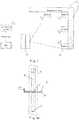
- Term "three points on one line”relates to a target spot of an accelerator, a central line of a detector tip, a central line of a collimator which are coplanar, and adjustments of "three points on one line” are intended to ensure that the target spot of the accelerator, the central line of the detector tip, and the central line of the collimator (sometimes including a central line of a calibrating device and the like) are located in one reference plane, as shown in Fig. 1 .
- alignment of the target spot of the accelerator, the central line of the detector tip, and the central line of the collimatoris manually measured by using a laser theodolite.
- a vertical line of a reticle of the theodoliteis arranged to coincide with central lines of detectors on upper and lower ends of a detector vertical arm, and to align with a center of the target spot as far as possible.
- a detector arm mountis generally used in many existing movable inspection systems, and needs to be unfolded quickly for operation after these movable inspection systems reach a new inspection site.
- the detector arm or mountas a mechanical structure, needs to be further adjusted so that the ray source, the collimator and the detector are located within one plane.
- US 2009/086907 A1discloses a dual-energy x-ray imaging system for searching a moving automobile for concealed objects.
- US 2011/274242 A1discloses an apparatus for X-ray scanning of vehicles.
- CN 103185891 Adiscloses a measurement device for accelerator ray bundles.
- US 2014/192958 A1discloses methods and an x-ray system for dynamically regulating x-ray dose.
- US 2014/321588 A1describes systems and methods for detecting specific classes of materials in transmission images and clearing or confirming their presence.
- US 2009/116614 A1discloses a portable inspection system for generating an image representation of target objects using a radiation source.
- CN 200993644discloses a x, gamma radial beam flux center check device, which comprises a detector module, a detector pen rack, a fixing support, a rotary support, an axle and an axle sleeve.
- JP H 1123482discloses a method for adjusting irradiation position with beam, foreign matter detecting apparatus using laser beam, scanning electron microscope and composition analyzing apparatus.
- CN 1133440 Adiscloses a self-scanned radiation detecting system for large-size body includes radiation source, collimating tower, detection tower, guide tracks and scanning portal frame.
- an object of the present disclosureis aimed to solve at least one of the above problems so as to achieve quick alignment of the ray beam and the detector module of the inspection system.
- an alignment systemfor a container or vehicle inspection system in which X or Gamma rays are applied, wherein the container or vehicle inspection system comprises a detector module and is operable to perform an inspection on a container or vehicle by irradiating the container or vehicle with a ray and detecting the ray transmitted from the container or vehicle using the detector module, wherein the alignment system comprises a measuring module, which includes a sensor row or a sensor array consisting of a plurality of sensors each configured to measure an intensity of the ray, wherein the sensor row or the sensor array is arranged along a direction perpendicular to a longitudinal central line of the detector module such that one sensor in the sensor row or at least one column of sensors in the sensor array is arranged on the longitudinal central line of the detector module of the container or vehicle inspection system, so that it is determined that the ray is aligned with the detector module when an intensity value of the ray measured by the one sensor or the at least one column of sensors of the measuring module arranged on the longitudinal central
- an inspection system for a container or a vehicle in which X rays or Gamma rays are appliedcomprising an ray source, a collimator, a detector arm and a detector module mounted on the detector arm, the ray source, the collimator and the detector module being arranged to form an inspection passage, rays emitted from the ray source passing through collimator, irradiating onto an inspected object and collected by the detector module so as to complete inspection, wherein the inspection system further comprises the above alignment system.
- an alignment method for an inspection system for a container or a vehicle in which X rays or Gamma rays are appliedcomprising: arranging the above alignment system on the longitudinal central line of the detector module located on a detector arm of the container or vehicle inspection system; arranging a ray source, a collimator and the detector module of the container or vehicle inspection system to form an inspection passage, the ray source emitting rays, which pass through the collimator and are received by the measuring module of the alignment system and the detector module; determining a position of a main ray beam based on ray intensity maximum values fed back from respective sensors of the measuring module; calculating a difference between a position on the detector module to which the main ray beam irradiates and the position of the longitudinal central line of the detector module; and adjusting the position of the ray source, the collimator or the detector module so that the position on the detector module to which the main ray beam irradiates coincides with the position of the
- a container or vehicle inspection systemin which X or Gamma rays are applied, comprises a ray source 1, a collimator 2 and a detector module 3 mounted on a detector arm.
- the ray source 1may be an X-ray accelerator or a Gamma ray accelerator.
- the collimator 2may be arranged at a ray outlet of the accelerator.
- desired raysmay be obtained by using other devices, for example, a device for directly emitting collimated rays.
- the detector module 3is provided on the detector arm 4.
- the detector arm 4comprises a detector transverse arm 41 and a detector vertical arm 42, and when the detector arm 4 is unfolded, the detectors 3 on the detector transverse arm 41 and the detector vertical arm 42 receive a ray beam collimated by the collimator 2 and transmitted through an inspected object, thereby achieving inspection. That is, in use, the ray source 1, the collimator 2 and the detector module 3 forms an inspection passage, as shown in Fig. 2 .
- the container or vehicle inspection systemin which X or Gamma rays are applied, further comprises an alignment system configured to align the ray source 1, the collimator 2 and the detector module 3.
- the alignment systemcomprises a measuring module 5.
- the measuring module 5is arranged on the detector module 3.
- the measuring module 5is arranged on the arm or mount 4 of the detector module 3.
- the measuring module 5is arranged to receive rays emitted from the ray source 1. As shown in Fig. 3 , the measuring module 5 extends in a transverse direction, and the detector module 3 extends in a longitudinal direction.
- the measuring module 5in order to determine the position of the detector module 3, the measuring module 5 is located at the position of the detector module 3 of the inspection system, so that the orientation of the collimator 2, that is, the position of a point of fall of the ray, is measured by the measuring module 5, and according to the measurement, the collimator 2 is adjusted to face towards the detector module 3.
- the measuring module 5is arranged on the detector arm 4 provided with the detector module 3, and it is ensured that a central line 3' of the detector module 3 in a transverse direction or a central line of the detector arm 4 in the transverse direction corresponds to a certain known portion of the measuring module 5, for example, to a middle point 5' of the measuring module 5.
- the central line 3' of the detector module 3is the same as the central line of the detector arm or mount 4, that is, the detectors are arranged in a vertical direction, and the detector arm 4 is divided into two equal halves by the central line 3' extending in the vertical direction.
- the measuring module 5is provided on the detector arm 4, as shown in Figs. 2 and 3 .
- the measuring module 5consists of a plurality of detector crystals 6, which have sizes smaller than those of detector crystals 6 of the imaging detector module 3 of the inspection system, or are small-sized detectors when compared to the detector crystals 6 of the imaging detector module 3 of the inspection system.
- the width of each small-sized detector crystal 6 of the measuring module 5may be 1/n of width D of the measuring module 5, where n is an integer and may be selected as required.
- the measuring module 5may consist of several small-sized detector crystals 6, which are arranged side by side to form a slender or elongate block body.
- the total width of the measuring module 5is larger than the width of the detector module 3 of the system, as shown in Fig. 4 .
- the length direction of the measuring module 5extends in the transverse direction of the detector module 3.
- the measuring module 5may be mechanically positioned on the detector module 3, and the elongate measuring module 5 may be arranged such that its middle point is located on the central line of the detector arm 4.
- the length extending direction of the elongate measuring module 5is perpendicular to the length extending direction of the detector arm 4. As such, a specific position of a center of a beam may be finely and quantificationally measured.
- Data measured by each measuring module 5may be transmitted to a computer for analysis.
- the total width of the measuring module 5is four to five times of the width of the detector module 3 of the system.
- the width of the detector module 3is 10mm
- the width of each small-sized detector crystal 6 of the measuring module 5is 1.5mm
- a ray beamirradiates the measuring module 5 after being collimated by the collimator 2, the collimated rays are incident onto the plurality of detector crystals 6 of the measuring module 5, where a ray intensity received by a detector crystal 6 onto which the rays are being incident is the greatest, and energy of rays received by the detector crystals 6 adjacent to the detector crystal 6 onto which the rays are being incident is gradually reduced, that is, the ray intensities measured by the detector crystals 6 reduce as distances at which they are located away from the detector crystal 6 onto which the rays are being incident increase.
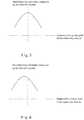
- Fig. 5is a schematic diagram showing a curve formed by intensity values respectively measured by the thirty two detector crystals 6 when the center of the measuring module 5 is located on the central line of the detector arm 4.
- the ray intensity detected by the detector crystal 6 at the middle of the measuring module 5is the strongest, that is, the highest point in the curve of the figure (the Y axis in the Figure shows normalized values of the measured ray intensities).
- Ray intensities measured by the detector crystals 6 located away from the middle point of the measuring module 5reduce as distances between these detector crystals 6 and the middle point.
- the operatormay directly determine the position of a peak of the rays according to positions on the curve and thus directly determine a direction to which an adjustment is to be made.
- Fig. 6 and Fig. 7are schematic diagrams respectively showing intensity curves measured when the collimator 2 deviates from the central line of the detector arm 4.
- deviation of the peak on the intensity curve from the Y axismay be used to indicate deviation of the collimator 2 or X-ray (or misalignment of the detector module; it will be understood by those skilled in the art that the misalignment is relative, that is, relates to relative positions between the combination of the X-rays and the collimator on an emitting side and the detector module on a receiving side), and the intensity peak can be adjusted onto the Y axis by adjusting the direction of the collimator 2 to face or align with the central line of the detector arm 4.
- the operatorcan directly judge the deviation and approximately estimate deviation amount through the deviation of the peak of the curve from the Y axis, thereby the alignment operation is easy.
- the alignment methodis simple and explicit, adjustment is direct and quick, so that it is convenient for the operator to quickly complete preparation work before inspection.
- the detector modulemay be adjusted rightward. If the mount on which the detector module is provided is fixed, the X-rays and collimator are adjusted so that the ray beam or ray beams move leftward. In practice operation, the operator observes the curve to make a direct judgement without trying to find out adjustment direction, so that the preparation work before inspection is easy and quick.
- An adjustment devicemay be provided to adjust the orientation of the collimator 2.
- a motor and a pivoting devicemay be provided, and the motor drives the pivoting device to pivot the collimator 2 so as to adjust the orientation of the collimator 2.
- automated adjustmentmay be achieved.
- a method of aligning an accelerator and a detector by using an X or Gamma ray container or vehicle inspection systemcomprises steps of: 1) emitting rays by the accelerator; 2) measuring an ray intensity distribution by using the measuring module 5; 3) determining relative positions of the ray source 1, the collimator 2 and the arm 4, and making an adjustment; 4) repeating the steps 2, 3, until the ray beam collimated by the collimator 2 is aligned with the detector module 3.
- the operatormay adjust the collimator 2 rightward so that the intensity peak of the curve shown in Fig. 6 is moved to the Y axis.
- the operatormay adjust the collimator 2 leftward so that the intensity peak of the curve shown in Fig. 6 is moved to the Y axis.
- relative position relationship between the ray source 1, the collimator 2 and the arm or mount 4may be determined, and position offset and angle deflection may be calculated to correct the system, so that the intensity distribution measured by all detector modules 3 is a parabola-like curve, as shown in Fig. 5 .
- a certain detector crystal 6 of the measuring module 5is located on the central line of the detector module 3. Since it is known that the detector crystal 6 is located on the central line, it only needs to adjust the orientation of the collimator 2 so that the detected ray intensity maximum value is positioned at the position of the known detector crystal 6, thereby it can be determined that the collimator 2 is aligned with the central line of the detector module 3. That is, in this embodiment, the center of the measuring module 5 is not located on the central line of the detector module 3.
- the measuring module 5is integrated into a whole.
- the measuring module 5is an elongate measuring module 5, which may be an array consisting of a set of sensors each located at a defined and known position.
- the intensity of the ray beam received by each sensoris known. That is, the intensity of the ray beam received by each position is known.
- the orientation of the collimator 2may be determined by viewing the position of the peak in the ray beam intensities. Similar to the above embodiments, the orientation of the collimator 2 may be adjusted so that the ray beam emitted from the collimator 2 faces toward a desired position, for example, toward the central line of the detector module 3.
- an alignment system for a container or vehicle inspection systemcomprises a measuring module 5, which is a sensor array consisting of a plurality of sensors each configured to measure ray intensity.
- a column 7 of sensors of the measuring moduleis arranged on a longitudinal central line of a detector module of the container or vehicle inspection system. It is determined that rays are aligned with the detector module when a ray intensity value measured by the column of sensors (or a number of columns of small-sized sensors if the small-sized sensor of the measuring module has a volume much smaller than that of the detector module) of the measuring module arranged on the longitudinal central line of the detector module ray intensity value is a maximum value of a ray intensity value curve.
- the detector crystal 6may has a certain volume, and the measuring module 5 is substantially transversely arranged along the detector arm 4, thus the technique solutions of the present disclosure are possible when an angle between the measuring module 5 and the detector arm 4 is in a certain range around 90 degrees.
- an alignment method for aligning a container or vehicle inspection systemcomprises a ray source 1, a collimator 2 and a detector module 3 mounted on a detector arm 4, the ray source 1, the collimator 2 and the detector module 3 being arranged to form an inspection passage, rays emitted from the ray source 1 passing through collimator 2, irradiating onto an inspected object and collected by the detector module 3 so as to complete inspection.
- the alignment methodcomprises at least providing a measuring module 5, the measuring module 5 being arranged to receive rays emitted from the ray source 1 and collimated by the collimator 2.
- the alignment methodfurther comprises determining a position of a main ray beam based on ray intensity peak values measured by the measuring module 5. It is determined that the main ray beam emitted from the ray source 1 and passing through the collimator 2 has be aligned with the detector module 3 when measurement from the measuring module 5 shows that the ray beam detected at the longitudinal central line of the detector module 3 has the largest intensity (that is, is the main ray beam).
- the ray beam described in the present disclosuremay be rays in any form for irradiation, for example, may be a pen shaped beam, a fan ray beam or any other desired ray forms.
Landscapes
- Physics & Mathematics (AREA)
- High Energy & Nuclear Physics (AREA)
- Life Sciences & Earth Sciences (AREA)
- General Life Sciences & Earth Sciences (AREA)
- General Physics & Mathematics (AREA)
- Geophysics (AREA)
- Spectroscopy & Molecular Physics (AREA)
- Engineering & Computer Science (AREA)
- General Engineering & Computer Science (AREA)
- Measurement Of Radiation (AREA)
Description
- Embodiments of the present disclosure relate to the field of X or Gamma ray security inspection, and particularly, to an X or Gamma ray inspection system for inspecting an object such as a container or vehicle, and an alignment system and an alignment method for the inspection system.
- Term "three points on one line" relates to a target spot of an accelerator, a central line of a detector tip, a central line of a collimator which are coplanar, and adjustments of "three points on one line" are intended to ensure that the target spot of the accelerator, the central line of the detector tip, and the central line of the collimator (sometimes including a central line of a calibrating device and the like) are located in one reference plane, as shown in
Fig. 1 . - In an existing measurement method, alignment of the target spot of the accelerator, the central line of the detector tip, and the central line of the collimator is manually measured by using a laser theodolite. A vertical line of a reticle of the theodolite is arranged to coincide with central lines of detectors on upper and lower ends of a detector vertical arm, and to align with a center of the target spot as far as possible. This method is implemented through the human eye, and thus is insufficient in objectivity and accuracy, that is, is easily and greatly affected by placement and debugging of instruments and the visual sense of the measurer.
- Further, a detector arm mount is generally used in many existing movable inspection systems, and needs to be unfolded quickly for operation after these movable inspection systems reach a new inspection site. However, the detector arm or mount, as a mechanical structure, needs to be further adjusted so that the ray source, the collimator and the detector are located within one plane. Thus, there is a need to alignment system and method enabling accurate, quick and reliable alignment.
US 2009/086907 A1 discloses a dual-energy x-ray imaging system for searching a moving automobile for concealed objects.US 2011/274242 A1 discloses an apparatus for X-ray scanning of vehicles.CN 103185891 A discloses a measurement device for accelerator ray bundles.US 2014/192958 A1 discloses methods and an x-ray system for dynamically regulating x-ray dose.US 2014/321588 A1 describes systems and methods for detecting specific classes of materials in transmission images and clearing or confirming their presence.US 2009/116614 A1 discloses a portable inspection system for generating an image representation of target objects using a radiation source.CN 200993644 discloses a x, gamma radial beam flux center check device, which comprises a detector module, a detector pen rack, a fixing support, a rotary support, an axle and an axle sleeve.JP H 1123482 CN 1133440 A discloses a self-scanned radiation detecting system for large-size body includes radiation source, collimating tower, detection tower, guide tracks and scanning portal frame.- In view of the above, an object of the present disclosure is aimed to solve at least one of the above problems so as to achieve quick alignment of the ray beam and the detector module of the inspection system.
- According to an aspect of the present disclosure, there is provided an alignment system for a container or vehicle inspection system in which X or Gamma rays are applied, wherein the container or vehicle inspection system comprises a detector module and is operable to perform an inspection on a container or vehicle by irradiating the container or vehicle with a ray and detecting the ray transmitted from the container or vehicle using the detector module, wherein the alignment system comprises a measuring module, which includes a sensor row or a sensor array consisting of a plurality of sensors each configured to measure an intensity of the ray, wherein the sensor row or the sensor array is arranged along a direction perpendicular to a longitudinal central line of the detector module such that one sensor in the sensor row or at least one column of sensors in the sensor array is arranged on the longitudinal central line of the detector module of the container or vehicle inspection system, so that it is determined that the ray is aligned with the detector module when an intensity value of the ray measured by the one sensor or the at least one column of sensors of the measuring module arranged on the longitudinal central line of the detector module is a maximum value of an intensity value curve of the ray, wherein the intensity value curve of the ray is determined by intensity values measured by the plurality of sensors of the measuring module.
- According to another aspect of the present disclosure, there is provided an inspection system for a container or a vehicle in which X rays or Gamma rays are applied, comprising an ray source, a collimator, a detector arm and a detector module mounted on the detector arm, the ray source, the collimator and the detector module being arranged to form an inspection passage, rays emitted from the ray source passing through collimator, irradiating onto an inspected object and collected by the detector module so as to complete inspection, wherein the inspection system further comprises the above alignment system.
- According to a further aspect of the present disclosure, there is provided an alignment method for an inspection system for a container or a vehicle in which X rays or Gamma rays are applied, comprising: arranging the above alignment system on the longitudinal central line of the detector module located on a detector arm of the container or vehicle inspection system; arranging a ray source, a collimator and the detector module of the container or vehicle inspection system to form an inspection passage, the ray source emitting rays, which pass through the collimator and are received by the measuring module of the alignment system and the detector module; determining a position of a main ray beam based on ray intensity maximum values fed back from respective sensors of the measuring module; calculating a difference between a position on the detector module to which the main ray beam irradiates and the position of the longitudinal central line of the detector module; and adjusting the position of the ray source, the collimator or the detector module so that the position on the detector module to which the main ray beam irradiates coincides with the position of the longitudinal central line of the detector module.
Fig. 1 is a schematic diagram showing a plane where a ray source, a collimator and detectors of a detector module arranged on a detector arm are desired to be located;Fig. 2 is another schematic diagram showing a ray source, a collimator and detectors of a detector module arranged on a detector arm;Fig. 3a is a schematic diagram showing a measuring module according to an embodiment of the present disclosure, the measuring module being transversely arranged on a detector module;Fig. 3b is a schematic diagram showing a measuring module according to an embodiment of the present disclosure, the measuring module being transversely arranged on a detector module;Fig. 4 is a schematic diagram showing a particular size of a measuring module according to an embodiment of the present disclosure;Fig. 5 is a schematic diagram showing a ray intensity distribution measured by a measuring module when a collimator is positioned to align with a central line of a detector module; andFigs. 6 and7 are schematic diagrams showing ray intensity distributions measured by a measuring module when a collimator is positioned to deviate from a central line of a detector module.- Exemplary embodiments of the present invention will be described hereinafter in detail with reference to the attached drawings, wherein the like reference numbers refer to the like elements. In the following detailed description, for purposes of explanation, numerous specific details are set forth in order to provide a thorough understanding of the disclosed embodiments. It will be apparent, however, that one or more embodiments may be practiced without these specific details. In other instances, well-known structures and devices are schematically shown in order to simplify the drawings.
- In an embodiment of the present disclosure, a container or vehicle inspection system, in which X or Gamma rays are applied, comprises a
ray source 1, acollimator 2 and adetector module 3 mounted on a detector arm. Theray source 1 may be an X-ray accelerator or a Gamma ray accelerator. In order to obtain better collimated rays, thecollimator 2 may be arranged at a ray outlet of the accelerator. Those skilled in the art will understand that desired rays may be obtained by using other devices, for example, a device for directly emitting collimated rays. Thedetector module 3 is provided on the detector arm 4.Thedetector arm 4 comprises a detectortransverse arm 41 and a detectorvertical arm 42, and when thedetector arm 4 is unfolded, thedetectors 3 on the detectortransverse arm 41 and the detectorvertical arm 42 receive a ray beam collimated by thecollimator 2 and transmitted through an inspected object, thereby achieving inspection. That is, in use, theray source 1, thecollimator 2 and thedetector module 3 forms an inspection passage, as shown inFig. 2 . - The container or vehicle inspection system, in which X or Gamma rays are applied, further comprises an alignment system configured to align the
ray source 1, thecollimator 2 and thedetector module 3. - The alignment system comprises a
measuring module 5. Themeasuring module 5 is arranged on thedetector module 3. In one embodiment, themeasuring module 5 is arranged on the arm ormount 4 of thedetector module 3. Themeasuring module 5 is arranged to receive rays emitted from theray source 1. As shown inFig. 3 , themeasuring module 5 extends in a transverse direction, and thedetector module 3 extends in a longitudinal direction. - In an embodiment of the present disclosure, in order to determine the position of the
detector module 3, themeasuring module 5 is located at the position of thedetector module 3 of the inspection system, so that the orientation of thecollimator 2, that is, the position of a point of fall of the ray, is measured by themeasuring module 5, and according to the measurement, thecollimator 2 is adjusted to face towards thedetector module 3. In this embodiment, themeasuring module 5 is arranged on thedetector arm 4 provided with thedetector module 3, and it is ensured that a central line 3' of thedetector module 3 in a transverse direction or a central line of thedetector arm 4 in the transverse direction corresponds to a certain known portion of themeasuring module 5, for example, to a middle point 5' of themeasuring module 5. Herein, the central line 3' of thedetector module 3 is the same as the central line of the detector arm ormount 4, that is, the detectors are arranged in a vertical direction, and thedetector arm 4 is divided into two equal halves by the central line 3' extending in the vertical direction. - In an embodiment of the present disclosure, the
measuring module 5 is provided on thedetector arm 4, as shown inFigs. 2 and3 . Themeasuring module 5 consists of a plurality ofdetector crystals 6, which have sizes smaller than those ofdetector crystals 6 of theimaging detector module 3 of the inspection system, or are small-sized detectors when compared to thedetector crystals 6 of theimaging detector module 3 of the inspection system. Preferably, as shown inFig. 3a , the width of each small-sized detector crystal 6 of themeasuring module 5 may be 1/n of width D of themeasuring module 5, where n is an integer and may be selected as required. In other words, themeasuring module 5 may consist of several small-sized detector crystals 6, which are arranged side by side to form a slender or elongate block body. The total width of themeasuring module 5 is larger than the width of thedetector module 3 of the system, as shown inFig. 4 . The length direction of themeasuring module 5 extends in the transverse direction of thedetector module 3. - The
measuring module 5 may be mechanically positioned on thedetector module 3, and theelongate measuring module 5 may be arranged such that its middle point is located on the central line of thedetector arm 4. The length extending direction of theelongate measuring module 5 is perpendicular to the length extending direction of thedetector arm 4. As such, a specific position of a center of a beam may be finely and quantificationally measured. - Data measured by each
measuring module 5 may be transmitted to a computer for analysis. - In an unclaimed example not forming part of the presently claimed invention, the total width of the
measuring module 5 is four to five times of the width of thedetector module 3 of the system. For example, the width of thedetector module 3 is 10mm, the width of each small-sized detector crystal 6 of themeasuring module 5 is 1.5mm, and themeasuring module 5 consists of thirty two small-sized detector crystals 6 and thus its width is 32×1.5=48mm, as shown inFig. 4 . - When the
ray source 1 emits rays, a ray beam irradiates the measuringmodule 5 after being collimated by thecollimator 2, the collimated rays are incident onto the plurality ofdetector crystals 6 of themeasuring module 5, where a ray intensity received by adetector crystal 6 onto which the rays are being incident is the greatest, and energy of rays received by thedetector crystals 6 adjacent to thedetector crystal 6 onto which the rays are being incident is gradually reduced, that is, the ray intensities measured by thedetector crystals 6 reduce as distances at which they are located away from thedetector crystal 6 onto which the rays are being incident increase.Fig. 5 is a schematic diagram showing a curve formed by intensity values respectively measured by the thirty twodetector crystals 6 when the center of themeasuring module 5 is located on the central line of thedetector arm 4. - As can be seen from
Fig. 5 , since the collimated rays are aligned with the central line of thedetector arm 4, the ray intensity detected by thedetector crystal 6 at the middle of themeasuring module 5 is the strongest, that is, the highest point in the curve of the figure (the Y axis in the Figure shows normalized values of the measured ray intensities). Ray intensities measured by thedetector crystals 6 located away from the middle point of themeasuring module 5 reduce as distances between thesedetector crystals 6 and the middle point. According to embodiments of the present disclosure, it is advantageous to determine alignment by using the curve shown inFig. 5 , for example, the operator may directly determine the position of a peak of the rays according to positions on the curve and thus directly determine a direction to which an adjustment is to be made. - When the
collimator 2 is not aligned with the middle point of themeasuring module 5, that is, not aligned with the central line of thedetector arm 4, the highest point on the curve shown inFig. 5 will deviate from the middle point of the measuring module 5 (because thedetector crystals 6 are fixed in position, the position of themiddle detector crystal 6 is known, and measured ray intensity value fall on the Y axis). Fig. 6 andFig. 7 are schematic diagrams respectively showing intensity curves measured when thecollimator 2 deviates from the central line of thedetector arm 4. In the present disclosure, deviation of the peak on the intensity curve from the Y axis may be used to indicate deviation of thecollimator 2 or X-ray (or misalignment of the detector module; it will be understood by those skilled in the art that the misalignment is relative, that is, relates to relative positions between the combination of the X-rays and the collimator on an emitting side and the detector module on a receiving side), and the intensity peak can be adjusted onto the Y axis by adjusting the direction of thecollimator 2 to face or align with the central line of thedetector arm 4. With such a curve analogous to a parabola, the operator can directly judge the deviation and approximately estimate deviation amount through the deviation of the peak of the curve from the Y axis, thereby the alignment operation is easy.- Thus, with the technique solutions provided according to embodiments of the present disclosure, uncertainty and randomicity of manual operations and adverse effects on subsequent inspection due to the randomicity can be avoided, and the alignment method is simple and explicit, adjustment is direct and quick, so that it is convenient for the operator to quickly complete preparation work before inspection. When the operator observes that the peak of the curve is on the right side of the Y axis, the detector module may be adjusted rightward. If the mount on which the detector module is provided is fixed, the X-rays and collimator are adjusted so that the ray beam or ray beams move leftward. In practice operation, the operator observes the curve to make a direct judgement without trying to find out adjustment direction, so that the preparation work before inspection is easy and quick.
- An adjustment device may be provided to adjust the orientation of the
collimator 2. For example, a motor and a pivoting device may be provided, and the motor drives the pivoting device to pivot thecollimator 2 so as to adjust the orientation of thecollimator 2. Thus, automated adjustment may be achieved. - According to an unclaimed example not forming part of the presently claimed invention, a method of aligning an accelerator and a detector by using an X or Gamma ray container or vehicle inspection system comprises steps of: 1) emitting rays by the accelerator; 2) measuring an ray intensity distribution by using the
measuring module 5; 3) determining relative positions of theray source 1, thecollimator 2 and thearm 4, and making an adjustment; 4) repeating thesteps collimator 2 is aligned with thedetector module 3. - Specifically, for example, when a curve shown in
Fig. 6 is displayed, the operator may adjust thecollimator 2 rightward so that the intensity peak of the curve shown inFig. 6 is moved to the Y axis. When a curve shown in Fig. 9 is displayed, the operator may adjust thecollimator 2 leftward so that the intensity peak of the curve shown inFig. 6 is moved to the Y axis. - When the target spot of the accelerator, the central line of the detector tip and the central line of the
collimator 2 are completely aligned with each other, signal intensities of X or Gamma rays received byrespective detector crystals 6 of each measuringmodule 5 would be those shown inFig. 5 , in order words, the center of the ray beam may impinge the middlemost portion of themeasuring module 5, that is, the tip central line of eachdetector module 3. - According to the ray intensity distribution measured by
respective detector modules 3 on the arm ormount 4, relative position relationship between theray source 1, thecollimator 2 and the arm ormount 4 may be determined, and position offset and angle deflection may be calculated to correct the system, so that the intensity distribution measured by alldetector modules 3 is a parabola-like curve, as shown inFig. 5 . - In another embodiment according to the present disclosure, a
certain detector crystal 6 of themeasuring module 5 is located on the central line of thedetector module 3. Since it is known that thedetector crystal 6 is located on the central line, it only needs to adjust the orientation of thecollimator 2 so that the detected ray intensity maximum value is positioned at the position of the knowndetector crystal 6, thereby it can be determined that thecollimator 2 is aligned with the central line of thedetector module 3. That is, in this embodiment, the center of themeasuring module 5 is not located on the central line of thedetector module 3. - In a further embodiment according to the present disclosure, the measuring
module 5 is integrated into a whole. The measuringmodule 5 is anelongate measuring module 5, which may be an array consisting of a set of sensors each located at a defined and known position. Thus, the intensity of the ray beam received by each sensor is known. That is, the intensity of the ray beam received by each position is known. Accordingly, the orientation of thecollimator 2 may be determined by viewing the position of the peak in the ray beam intensities. Similar to the above embodiments, the orientation of thecollimator 2 may be adjusted so that the ray beam emitted from thecollimator 2 faces toward a desired position, for example, toward the central line of thedetector module 3. - In a further embodiment according to the present disclosure, as shown in
Fig. 3b , an alignment system for a container or vehicle inspection system comprises ameasuring module 5, which is a sensor array consisting of a plurality of sensors each configured to measure ray intensity. A column 7 of sensors of the measuring module is arranged on a longitudinal central line of a detector module of the container or vehicle inspection system. It is determined that rays are aligned with the detector module when a ray intensity value measured by the column of sensors (or a number of columns of small-sized sensors if the small-sized sensor of the measuring module has a volume much smaller than that of the detector module) of the measuring module arranged on the longitudinal central line of the detector module ray intensity value is a maximum value of a ray intensity value curve. - It is known for those skilled in the art that the
detector crystal 6 may has a certain volume, and themeasuring module 5 is substantially transversely arranged along thedetector arm 4, thus the technique solutions of the present disclosure are possible when an angle between the measuringmodule 5 and thedetector arm 4 is in a certain range around 90 degrees. - According to an embodiment of the present disclosure, there is provided an alignment method for aligning a container or vehicle inspection system, according to
claim 6. The inspection system comprises aray source 1, acollimator 2 and adetector module 3 mounted on adetector arm 4, theray source 1, thecollimator 2 and thedetector module 3 being arranged to form an inspection passage, rays emitted from theray source 1 passing throughcollimator 2, irradiating onto an inspected object and collected by thedetector module 3 so as to complete inspection. The alignment method comprises at least providing ameasuring module 5, the measuringmodule 5 being arranged to receive rays emitted from theray source 1 and collimated by thecollimator 2. The alignment method further comprises determining a position of a main ray beam based on ray intensity peak values measured by the measuringmodule 5. It is determined that the main ray beam emitted from theray source 1 and passing through thecollimator 2 has be aligned with thedetector module 3 when measurement from the measuringmodule 5 shows that the ray beam detected at the longitudinal central line of thedetector module 3 has the largest intensity (that is, is the main ray beam). - It will be appreciated by those skilled in the art that the ray beam described in the present disclosure may be rays in any form for irradiation, for example, may be a pen shaped beam, a fan ray beam or any other desired ray forms.
- Although several exemplary embodiments have been shown and described, it would be appreciated by those skilled in the art that various changes or modifications may be made in these embodiments without departing from the disclosure, the scope of which is defined in the claims
Claims (6)
- An alignment system for a container or vehicle inspection system in which X rays or Gamma rays are applied, wherein the container or vehicle inspection system comprises a detector module (3)
and is operable to perform an inspection on a container or vehicle by irradiating the container or vehicle with a ray and detecting the ray transmitted from the container or vehicle using the detector module,characterised in that:the alignment system comprises a measuring module (5), which includes a sensor row or a sensor array consisting a plurality of sensors (6) each configured to measure an intensity of the ray;wherein the sensor row or the sensor array is arranged along a direction perpendicular to a longitudinal central line (3') of the detector module such that one sensor in the sensor row or at least one column of sensors in the sensor array is arranged on the longitudinal central line of the detector module (3) of the container or vehicle inspection system, so that it is determined that the ray is aligned with the detector module when an intensity value of the ray measured by the one sensor or the at least one column of sensors of the measuring module arranged on the longitudinal central line of the detector module is a maximum value of an intensity value curve of the ray,wherein the intensity value curve of the ray is determined by intensity values measured by the plurality of sensors of the measuring module. - The alignment system according to claim 1, wherein
the sensor is a small-sized detector having a size smaller than a size of a detector crystal of the detector module of the container or vehicle inspection system, and one small-sized detector of the measuring module is arranged on the longitudinal central line of the detector module of the container or vehicle inspection system. - The alignment system according to claim 1 or 2, wherein
the sensor arranged on the longitudinal central line of the detector module of the container or vehicle inspection system is a sensor located at a middle point of the measuring module. - The alignment system according to claim 3, wherein
it is determined that rays passing through a collimator (2) have been aligned with the detector module when a ray intensity value measured by the sensor of the measuring module located at the middle point of the detector module is the maximum. - An inspection system for a container or a vehicle in which X rays or Gamma rays are applied, comprising a ray source (1), a collimator (2), a detector arm (4, 41, 42) and a detector module (3) mounted on the detector arm, the ray source, the collimator and the detector module being arranged to form an inspection passage, rays emitted from the ray source passing through the collimator, irradiating onto an object to be inspected and collected by the detector module so as to complete inspection,
wherein the inspection system further comprises the alignment system according to any one of preceding claims. - An alignment method for an inspection system for a container or a vehicle in which X rays or Gamma rays are applied, comprising:arranging the alignment system according to any one of claims 1 to 4 on the longitudinal central line of the detector module located on a detector arm of the container or vehicle inspection system;arranging a ray source, a collimator and the detector module of the container or vehicle inspection system to form an inspection passage, the ray source emitting rays, which pass through the collimator and are received by the measuring module of the alignment system and the detector module;determining a position of a main ray beam based on ray intensity maximum values fed back from respective sensors of the measuring module;calculating a difference between a position on the detector module to which the main ray beam irradiates and the position of the longitudinal central line of the detector module; andadjusting the position of the ray source, the collimator or the detector module so that the position on the detector module to which the main ray beam irradiates coincides with the position of the longitudinal central line of the detector module.
Priority Applications (1)
| Application Number | Priority Date | Filing Date | Title |
|---|---|---|---|
| PL15199611TPL3032288T3 (en) | 2014-12-11 | 2015-12-11 | Alignment system and method for container or vehicle inspection system |
Applications Claiming Priority (1)
| Application Number | Priority Date | Filing Date | Title |
|---|---|---|---|
| CN201410767544.0ACN104634796B (en) | 2014-12-11 | 2014-12-11 | For container or vehicle inspection system to Barebone and alignment methods |
Publications (2)
| Publication Number | Publication Date |
|---|---|
| EP3032288A1 EP3032288A1 (en) | 2016-06-15 |
| EP3032288B1true EP3032288B1 (en) | 2022-01-12 |
Family
ID=53213788
Family Applications (1)
| Application Number | Title | Priority Date | Filing Date |
|---|---|---|---|
| EP15199611.3AActiveEP3032288B1 (en) | 2014-12-11 | 2015-12-11 | Alignment system and method for container or vehicle inspection system |
Country Status (5)
| Country | Link |
|---|---|
| US (1) | US9910184B2 (en) |
| EP (1) | EP3032288B1 (en) |
| CN (1) | CN104634796B (en) |
| PL (1) | PL3032288T3 (en) |
| WO (1) | WO2016091132A1 (en) |
Families Citing this family (12)
| Publication number | Priority date | Publication date | Assignee | Title |
|---|---|---|---|---|
| CN104634796B (en)* | 2014-12-11 | 2017-12-12 | 清华大学 | For container or vehicle inspection system to Barebone and alignment methods |
| CN106290419B (en)* | 2016-08-31 | 2024-08-20 | 同方威视技术股份有限公司 | Movable split type inspection system and method |
| CN106442585A (en)* | 2016-10-17 | 2017-02-22 | 北京君和信达科技有限公司 | Back scattering radiation imaging system |
| CN109683204B (en)* | 2017-10-19 | 2020-07-28 | 北京君和信达科技有限公司 | Radiation imaging device adjusting method |
| CN111374692A (en)* | 2018-12-27 | 2020-07-07 | 有方(合肥)医疗科技有限公司 | Oral CT |
| CN111374693A (en)* | 2018-12-27 | 2020-07-07 | 有方(合肥)医疗科技有限公司 | Oral CT |
| CN110057848A (en)* | 2019-04-17 | 2019-07-26 | 苏州曼德克光电有限公司 | A kind of system and method being aligned for detector array with radiographic source |
| CN114222915B (en)* | 2019-08-16 | 2024-09-06 | 卓缤科技贸易公司 | X-ray automated calibration and monitoring |
| CN113406710A (en)* | 2020-03-17 | 2021-09-17 | 同方威视技术股份有限公司 | Detector module, detector device and inspection device |
| CN113945989B (en)* | 2021-09-08 | 2024-12-03 | 浙江华视智检科技有限公司 | Radiation source fine-tuning system and method |
| CN114121334B (en)* | 2021-11-16 | 2025-04-22 | 湖州霍里思特智能科技有限公司 | A ray collimation adjustment device |
| CN114563428B (en)* | 2022-03-09 | 2025-08-01 | 河南省科学院同位素研究所有限责任公司 | Corrosion positioning non-contact evaluation system for steel structure in high-altitude enclosed space |
Citations (4)
| Publication number | Priority date | Publication date | Assignee | Title |
|---|---|---|---|---|
| CN1133440A (en)* | 1995-03-31 | 1996-10-16 | 清华大学 | Self-scanning radiation detection system for large objects |
| JPH1123482A (en)* | 1997-06-30 | 1999-01-29 | Advantest Corp | Method for adjusting irradiation position with beam, foreign matter detecting apparatus using laser beam, scanning electron microscope and composition analyzing apparatus |
| CN200993644Y (en)* | 2006-12-30 | 2007-12-19 | 清华同方威视技术股份有限公司 | X-gamma ray beam detecting device for large-sized containers |
| US20090116614A1 (en)* | 2002-07-23 | 2009-05-07 | Andreas Kotowski | Cargo Scanning System |
Family Cites Families (14)
| Publication number | Priority date | Publication date | Assignee | Title |
|---|---|---|---|---|
| US7963695B2 (en)* | 2002-07-23 | 2011-06-21 | Rapiscan Systems, Inc. | Rotatable boom cargo scanning system |
| US6995372B2 (en)* | 2003-02-12 | 2006-02-07 | Voith Paper Patent Gmbh | Nuclear gauge for measuring a characteristic of a sheet material with sheet position and alignment compensation |
| CN1963476A (en)* | 2005-11-09 | 2007-05-16 | 清华同方威视技术股份有限公司 | A centre alignment apparatus for ray bundle |
| CN2890902Y (en)* | 2005-11-09 | 2007-04-18 | 清华同方威视技术股份有限公司 | Ray beam center aligning device |
| US20080298546A1 (en)* | 2007-05-31 | 2008-12-04 | General Electric Company | Cargo container inspection method |
| US7742568B2 (en)* | 2007-06-09 | 2010-06-22 | Spectrum San Diego, Inc. | Automobile scanning system |
| CN102023306B (en)* | 2009-09-11 | 2013-10-09 | 同方威视技术股份有限公司 | Accelerator dose monitoring device and calibration method, accelerator target point P offset monitoring method |
| CN101813642A (en)* | 2009-12-31 | 2010-08-25 | 苏州和君科技发展有限公司 | Microscopy CT imaging device with three-free degree motion control and correcting method thereof |
| US10393915B2 (en)* | 2010-02-25 | 2019-08-27 | Rapiscan Systems, Inc. | Integrated primary and special nuclear material alarm resolution |
| BR112012021696A2 (en)* | 2010-05-05 | 2018-05-08 | Nauchno Proizvodstvennoe Chastnoe Unitarnoe Predpriyatie Adani | vehicle and cargo inspection system. |
| CN103645494B (en)* | 2011-12-30 | 2016-04-06 | 同方威视技术股份有限公司 | Measure the method for the energy of accelerator beam |
| CN104903708B (en)* | 2013-01-04 | 2019-09-10 | 美国科技工程公司 | Dynamic dose in X-ray examination reduces |
| CN204314235U (en)* | 2014-12-11 | 2015-05-06 | 清华大学 | For container or the check system of vehicle and the alignment system for this check system |
| CN104634796B (en)* | 2014-12-11 | 2017-12-12 | 清华大学 | For container or vehicle inspection system to Barebone and alignment methods |
- 2014
- 2014-12-11CNCN201410767544.0Apatent/CN104634796B/enactiveActive
- 2015
- 2015-12-07WOPCT/CN2015/096537patent/WO2016091132A1/enactiveApplication Filing
- 2015-12-11PLPL15199611Tpatent/PL3032288T3/enunknown
- 2015-12-11EPEP15199611.3Apatent/EP3032288B1/enactiveActive
- 2015-12-11USUS14/965,978patent/US9910184B2/enactiveActive
Patent Citations (4)
| Publication number | Priority date | Publication date | Assignee | Title |
|---|---|---|---|---|
| CN1133440A (en)* | 1995-03-31 | 1996-10-16 | 清华大学 | Self-scanning radiation detection system for large objects |
| JPH1123482A (en)* | 1997-06-30 | 1999-01-29 | Advantest Corp | Method for adjusting irradiation position with beam, foreign matter detecting apparatus using laser beam, scanning electron microscope and composition analyzing apparatus |
| US20090116614A1 (en)* | 2002-07-23 | 2009-05-07 | Andreas Kotowski | Cargo Scanning System |
| CN200993644Y (en)* | 2006-12-30 | 2007-12-19 | 清华同方威视技术股份有限公司 | X-gamma ray beam detecting device for large-sized containers |
Also Published As
| Publication number | Publication date |
|---|---|
| EP3032288A1 (en) | 2016-06-15 |
| PL3032288T3 (en) | 2022-05-09 |
| US9910184B2 (en) | 2018-03-06 |
| CN104634796B (en) | 2017-12-12 |
| CN104634796A (en) | 2015-05-20 |
| WO2016091132A1 (en) | 2016-06-16 |
| US20160170074A1 (en) | 2016-06-16 |
Similar Documents
| Publication | Publication Date | Title |
|---|---|---|
| EP3032288B1 (en) | Alignment system and method for container or vehicle inspection system | |
| US20240017095A1 (en) | Systems, methods, and devices for radiation beam asymmetry measurements using electronic portal imaging devices | |
| EP2929291B1 (en) | Device testing the horizontal dispersion of a laser beam and corresponding method | |
| US9562865B2 (en) | Method and apparatus for analysis of samples | |
| CN104316293B (en) | Device and method for determining parallelism of continuous zooming television optical axis | |
| CN114323571B (en) | Multi-optical-axis consistency detection method for photoelectric aiming system | |
| US20130329217A1 (en) | Laser System for Aligning a Bed Transport Mechanism in an Imaging System | |
| EP3249393B1 (en) | Two-dimensional x-ray detector position calibration and correction with diffraction pattern | |
| US20080210853A1 (en) | Medical apparatus and procedure for positioning a patient in an isocenter | |
| CN102813525A (en) | Digital radiography (DR) center calibration device and calibration method thereof | |
| JP5710332B2 (en) | Alignment adjustment method, alignment measurement method, and alignment jig | |
| CN204314235U (en) | For container or the check system of vehicle and the alignment system for this check system | |
| US10918889B2 (en) | LINAC quality control device | |
| KR101608669B1 (en) | Apparatus alignment of beam stopper | |
| CN211906985U (en) | Gamma ray collimation positioner | |
| Xiao et al. | Design of locating system on EAST horizontal Thomson scattering diagnostic | |
| CN103808748B (en) | Light-path system enabling test light path and imaging light path to be coaxial | |
| KR101500287B1 (en) | Center jig of gamma-ray irradiation apparatus for calibration | |
| US7651270B2 (en) | Automated x-ray optic alignment with four-sector sensor | |
| CN202486335U (en) | Physical Model System Tuning System for Container Imaging | |
| RU2413396C1 (en) | Laser centraliser for x-ray emitter | |
| KR101596748B1 (en) | Small angle x-ray scattering apparatus with tube align means and method for adjusting x-ray beam using the same | |
| CN210775283U (en) | Radiation imaging index testing equipment and inspection device | |
| US20240310308A1 (en) | Measurement object and method for verifying a calibration of an x-ray fluorescence device | |
| JP6914053B2 (en) | QA method and system for radiotherapy equipment or diagnostic equipment |
Legal Events
| Date | Code | Title | Description |
|---|---|---|---|
| PUAI | Public reference made under article 153(3) epc to a published international application that has entered the european phase | Free format text:ORIGINAL CODE: 0009012 | |
| 17P | Request for examination filed | Effective date:20151229 | |
| AK | Designated contracting states | Kind code of ref document:A1 Designated state(s):AL AT BE BG CH CY CZ DE DK EE ES FI FR GB GR HR HU IE IS IT LI LT LU LV MC MK MT NL NO PL PT RO RS SE SI SK SM TR | |
| AX | Request for extension of the european patent | Extension state:BA ME | |
| STAA | Information on the status of an ep patent application or granted ep patent | Free format text:STATUS: EXAMINATION IS IN PROGRESS | |
| 17Q | First examination report despatched | Effective date:20181106 | |
| GRAP | Despatch of communication of intention to grant a patent | Free format text:ORIGINAL CODE: EPIDOSNIGR1 | |
| STAA | Information on the status of an ep patent application or granted ep patent | Free format text:STATUS: GRANT OF PATENT IS INTENDED | |
| INTG | Intention to grant announced | Effective date:20210728 | |
| GRAS | Grant fee paid | Free format text:ORIGINAL CODE: EPIDOSNIGR3 | |
| GRAA | (expected) grant | Free format text:ORIGINAL CODE: 0009210 | |
| STAA | Information on the status of an ep patent application or granted ep patent | Free format text:STATUS: THE PATENT HAS BEEN GRANTED | |
| AK | Designated contracting states | Kind code of ref document:B1 Designated state(s):AL AT BE BG CH CY CZ DE DK EE ES FI FR GB GR HR HU IE IS IT LI LT LU LV MC MK MT NL NO PL PT RO RS SE SI SK SM TR | |
| REG | Reference to a national code | Ref country code:GB Ref legal event code:FG4D | |
| REG | Reference to a national code | Ref country code:CH Ref legal event code:EP | |
| REG | Reference to a national code | Ref country code:DE Ref legal event code:R096 Ref document number:602015076395 Country of ref document:DE | |
| REG | Reference to a national code | Ref country code:IE Ref legal event code:FG4D | |
| REG | Reference to a national code | Ref country code:AT Ref legal event code:REF Ref document number:1462750 Country of ref document:AT Kind code of ref document:T Effective date:20220215 | |
| REG | Reference to a national code | Ref country code:LT Ref legal event code:MG9D | |
| REG | Reference to a national code | Ref country code:NL Ref legal event code:MP Effective date:20220112 | |
| REG | Reference to a national code | Ref country code:AT Ref legal event code:MK05 Ref document number:1462750 Country of ref document:AT Kind code of ref document:T Effective date:20220112 | |
| PG25 | Lapsed in a contracting state [announced via postgrant information from national office to epo] | Ref country code:NL Free format text:LAPSE BECAUSE OF FAILURE TO SUBMIT A TRANSLATION OF THE DESCRIPTION OR TO PAY THE FEE WITHIN THE PRESCRIBED TIME-LIMIT Effective date:20220112 | |
| PG25 | Lapsed in a contracting state [announced via postgrant information from national office to epo] | Ref country code:SE Free format text:LAPSE BECAUSE OF FAILURE TO SUBMIT A TRANSLATION OF THE DESCRIPTION OR TO PAY THE FEE WITHIN THE PRESCRIBED TIME-LIMIT Effective date:20220112 Ref country code:RS Free format text:LAPSE BECAUSE OF FAILURE TO SUBMIT A TRANSLATION OF THE DESCRIPTION OR TO PAY THE FEE WITHIN THE PRESCRIBED TIME-LIMIT Effective date:20220112 Ref country code:PT Free format text:LAPSE BECAUSE OF FAILURE TO SUBMIT A TRANSLATION OF THE DESCRIPTION OR TO PAY THE FEE WITHIN THE PRESCRIBED TIME-LIMIT Effective date:20220512 Ref country code:NO Free format text:LAPSE BECAUSE OF FAILURE TO SUBMIT A TRANSLATION OF THE DESCRIPTION OR TO PAY THE FEE WITHIN THE PRESCRIBED TIME-LIMIT Effective date:20220412 Ref country code:LT Free format text:LAPSE BECAUSE OF FAILURE TO SUBMIT A TRANSLATION OF THE DESCRIPTION OR TO PAY THE FEE WITHIN THE PRESCRIBED TIME-LIMIT Effective date:20220112 Ref country code:HR Free format text:LAPSE BECAUSE OF FAILURE TO SUBMIT A TRANSLATION OF THE DESCRIPTION OR TO PAY THE FEE WITHIN THE PRESCRIBED TIME-LIMIT Effective date:20220112 Ref country code:ES Free format text:LAPSE BECAUSE OF FAILURE TO SUBMIT A TRANSLATION OF THE DESCRIPTION OR TO PAY THE FEE WITHIN THE PRESCRIBED TIME-LIMIT Effective date:20220112 Ref country code:BG Free format text:LAPSE BECAUSE OF FAILURE TO SUBMIT A TRANSLATION OF THE DESCRIPTION OR TO PAY THE FEE WITHIN THE PRESCRIBED TIME-LIMIT Effective date:20220412 | |
| PG25 | Lapsed in a contracting state [announced via postgrant information from national office to epo] | Ref country code:LV Free format text:LAPSE BECAUSE OF FAILURE TO SUBMIT A TRANSLATION OF THE DESCRIPTION OR TO PAY THE FEE WITHIN THE PRESCRIBED TIME-LIMIT Effective date:20220112 Ref country code:GR Free format text:LAPSE BECAUSE OF FAILURE TO SUBMIT A TRANSLATION OF THE DESCRIPTION OR TO PAY THE FEE WITHIN THE PRESCRIBED TIME-LIMIT Effective date:20220413 Ref country code:FI Free format text:LAPSE BECAUSE OF FAILURE TO SUBMIT A TRANSLATION OF THE DESCRIPTION OR TO PAY THE FEE WITHIN THE PRESCRIBED TIME-LIMIT Effective date:20220112 Ref country code:AT Free format text:LAPSE BECAUSE OF FAILURE TO SUBMIT A TRANSLATION OF THE DESCRIPTION OR TO PAY THE FEE WITHIN THE PRESCRIBED TIME-LIMIT Effective date:20220112 | |
| PG25 | Lapsed in a contracting state [announced via postgrant information from national office to epo] | Ref country code:IS Free format text:LAPSE BECAUSE OF FAILURE TO SUBMIT A TRANSLATION OF THE DESCRIPTION OR TO PAY THE FEE WITHIN THE PRESCRIBED TIME-LIMIT Effective date:20220512 | |
| REG | Reference to a national code | Ref country code:DE Ref legal event code:R097 Ref document number:602015076395 Country of ref document:DE | |
| PG25 | Lapsed in a contracting state [announced via postgrant information from national office to epo] | Ref country code:SM Free format text:LAPSE BECAUSE OF FAILURE TO SUBMIT A TRANSLATION OF THE DESCRIPTION OR TO PAY THE FEE WITHIN THE PRESCRIBED TIME-LIMIT Effective date:20220112 Ref country code:SK Free format text:LAPSE BECAUSE OF FAILURE TO SUBMIT A TRANSLATION OF THE DESCRIPTION OR TO PAY THE FEE WITHIN THE PRESCRIBED TIME-LIMIT Effective date:20220112 Ref country code:RO Free format text:LAPSE BECAUSE OF FAILURE TO SUBMIT A TRANSLATION OF THE DESCRIPTION OR TO PAY THE FEE WITHIN THE PRESCRIBED TIME-LIMIT Effective date:20220112 Ref country code:EE Free format text:LAPSE BECAUSE OF FAILURE TO SUBMIT A TRANSLATION OF THE DESCRIPTION OR TO PAY THE FEE WITHIN THE PRESCRIBED TIME-LIMIT Effective date:20220112 Ref country code:DK Free format text:LAPSE BECAUSE OF FAILURE TO SUBMIT A TRANSLATION OF THE DESCRIPTION OR TO PAY THE FEE WITHIN THE PRESCRIBED TIME-LIMIT Effective date:20220112 Ref country code:CZ Free format text:LAPSE BECAUSE OF FAILURE TO SUBMIT A TRANSLATION OF THE DESCRIPTION OR TO PAY THE FEE WITHIN THE PRESCRIBED TIME-LIMIT Effective date:20220112 | |
| PLBE | No opposition filed within time limit | Free format text:ORIGINAL CODE: 0009261 | |
| STAA | Information on the status of an ep patent application or granted ep patent | Free format text:STATUS: NO OPPOSITION FILED WITHIN TIME LIMIT | |
| PG25 | Lapsed in a contracting state [announced via postgrant information from national office to epo] | Ref country code:AL Free format text:LAPSE BECAUSE OF FAILURE TO SUBMIT A TRANSLATION OF THE DESCRIPTION OR TO PAY THE FEE WITHIN THE PRESCRIBED TIME-LIMIT Effective date:20220112 | |
| 26N | No opposition filed | Effective date:20221013 | |
| PG25 | Lapsed in a contracting state [announced via postgrant information from national office to epo] | Ref country code:SI Free format text:LAPSE BECAUSE OF FAILURE TO SUBMIT A TRANSLATION OF THE DESCRIPTION OR TO PAY THE FEE WITHIN THE PRESCRIBED TIME-LIMIT Effective date:20220112 | |
| REG | Reference to a national code | Ref country code:DE Ref legal event code:R119 Ref document number:602015076395 Country of ref document:DE | |
| P01 | Opt-out of the competence of the unified patent court (upc) registered | Effective date:20230528 | |
| PG25 | Lapsed in a contracting state [announced via postgrant information from national office to epo] | Ref country code:IT Free format text:LAPSE BECAUSE OF FAILURE TO SUBMIT A TRANSLATION OF THE DESCRIPTION OR TO PAY THE FEE WITHIN THE PRESCRIBED TIME-LIMIT Effective date:20220112 | |
| REG | Reference to a national code | Ref country code:CH Ref legal event code:PL | |
| GBPC | Gb: european patent ceased through non-payment of renewal fee | Effective date:20221211 | |
| REG | Reference to a national code | Ref country code:BE Ref legal event code:MM Effective date:20221231 | |
| PG25 | Lapsed in a contracting state [announced via postgrant information from national office to epo] | Ref country code:LU Free format text:LAPSE BECAUSE OF NON-PAYMENT OF DUE FEES Effective date:20221211 | |
| PG25 | Lapsed in a contracting state [announced via postgrant information from national office to epo] | Ref country code:LI Free format text:LAPSE BECAUSE OF NON-PAYMENT OF DUE FEES Effective date:20221231 Ref country code:IE Free format text:LAPSE BECAUSE OF NON-PAYMENT OF DUE FEES Effective date:20221211 Ref country code:GB Free format text:LAPSE BECAUSE OF NON-PAYMENT OF DUE FEES Effective date:20221211 Ref country code:DE Free format text:LAPSE BECAUSE OF NON-PAYMENT OF DUE FEES Effective date:20230701 Ref country code:CH Free format text:LAPSE BECAUSE OF NON-PAYMENT OF DUE FEES Effective date:20221231 | |
| PG25 | Lapsed in a contracting state [announced via postgrant information from national office to epo] | Ref country code:FR Free format text:LAPSE BECAUSE OF NON-PAYMENT OF DUE FEES Effective date:20221231 Ref country code:BE Free format text:LAPSE BECAUSE OF NON-PAYMENT OF DUE FEES Effective date:20221231 | |
| PG25 | Lapsed in a contracting state [announced via postgrant information from national office to epo] | Ref country code:HU Free format text:LAPSE BECAUSE OF FAILURE TO SUBMIT A TRANSLATION OF THE DESCRIPTION OR TO PAY THE FEE WITHIN THE PRESCRIBED TIME-LIMIT; INVALID AB INITIO Effective date:20151211 | |
| PG25 | Lapsed in a contracting state [announced via postgrant information from national office to epo] | Ref country code:CY Free format text:LAPSE BECAUSE OF FAILURE TO SUBMIT A TRANSLATION OF THE DESCRIPTION OR TO PAY THE FEE WITHIN THE PRESCRIBED TIME-LIMIT Effective date:20220112 | |
| PG25 | Lapsed in a contracting state [announced via postgrant information from national office to epo] | Ref country code:MK Free format text:LAPSE BECAUSE OF FAILURE TO SUBMIT A TRANSLATION OF THE DESCRIPTION OR TO PAY THE FEE WITHIN THE PRESCRIBED TIME-LIMIT Effective date:20220112 | |
| PG25 | Lapsed in a contracting state [announced via postgrant information from national office to epo] | Ref country code:MC Free format text:LAPSE BECAUSE OF FAILURE TO SUBMIT A TRANSLATION OF THE DESCRIPTION OR TO PAY THE FEE WITHIN THE PRESCRIBED TIME-LIMIT Effective date:20220112 | |
| PG25 | Lapsed in a contracting state [announced via postgrant information from national office to epo] | Ref country code:TR Free format text:LAPSE BECAUSE OF FAILURE TO SUBMIT A TRANSLATION OF THE DESCRIPTION OR TO PAY THE FEE WITHIN THE PRESCRIBED TIME-LIMIT Effective date:20220112 Ref country code:MC Free format text:LAPSE BECAUSE OF FAILURE TO SUBMIT A TRANSLATION OF THE DESCRIPTION OR TO PAY THE FEE WITHIN THE PRESCRIBED TIME-LIMIT Effective date:20220112 | |
| PG25 | Lapsed in a contracting state [announced via postgrant information from national office to epo] | Ref country code:MT Free format text:LAPSE BECAUSE OF FAILURE TO SUBMIT A TRANSLATION OF THE DESCRIPTION OR TO PAY THE FEE WITHIN THE PRESCRIBED TIME-LIMIT Effective date:20220112 | |
| PGFP | Annual fee paid to national office [announced via postgrant information from national office to epo] | Ref country code:PL Payment date:20241202 Year of fee payment:10 |