EP3030179B1 - Bipolar surgical instrument - Google Patents
Bipolar surgical instrumentDownload PDFInfo
- Publication number
- EP3030179B1 EP3030179B1EP13891305.8AEP13891305AEP3030179B1EP 3030179 B1EP3030179 B1EP 3030179B1EP 13891305 AEP13891305 AEP 13891305AEP 3030179 B1EP3030179 B1EP 3030179B1
- Authority
- EP
- European Patent Office
- Prior art keywords
- knife
- jaw members
- knife blade
- bipolar forceps
- housing
- Prior art date
- Legal status (The legal status is an assumption and is not a legal conclusion. Google has not performed a legal analysis and makes no representation as to the accuracy of the status listed.)
- Active
Links
- 230000007246mechanismEffects0.000claimsdescription65
- 238000007789sealingMethods0.000claimsdescription28
- 230000033001locomotionEffects0.000claimsdescription20
- 239000000758substrateSubstances0.000claimsdescription12
- 230000000694effectsEffects0.000claimsdescription11
- 230000000295complement effectEffects0.000claimsdescription4
- 238000013519translationMethods0.000claimsdescription3
- 239000012636effectorSubstances0.000description11
- 238000000034methodMethods0.000description5
- 210000004204blood vesselAnatomy0.000description4
- 238000003780insertionMethods0.000description4
- 230000037431insertionEffects0.000description4
- 238000002355open surgical procedureMethods0.000description4
- 230000009471actionEffects0.000description2
- 239000000463materialSubstances0.000description2
- 238000012986modificationMethods0.000description2
- 230000004048modificationEffects0.000description2
- 239000004033plasticSubstances0.000description2
- 230000004913activationEffects0.000description1
- 210000001367arteryAnatomy0.000description1
- 230000000740bleeding effectEffects0.000description1
- 239000000919ceramicSubstances0.000description1
- 238000005345coagulationMethods0.000description1
- 230000015271coagulationEffects0.000description1
- 239000004020conductorSubstances0.000description1
- 230000008878couplingEffects0.000description1
- 238000010168coupling processMethods0.000description1
- 238000005859coupling reactionMethods0.000description1
- 230000001419dependent effectEffects0.000description1
- 238000011161developmentMethods0.000description1
- 238000009297electrocoagulationMethods0.000description1
- 238000010438heat treatmentMethods0.000description1
- 230000023597hemostasisEffects0.000description1
- 239000002874hemostatic agentSubstances0.000description1
- 230000001939inductive effectEffects0.000description1
- 238000002347injectionMethods0.000description1
- 239000007924injectionSubstances0.000description1
- 238000001746injection mouldingMethods0.000description1
- 230000002452interceptive effectEffects0.000description1
- 239000002991molded plasticSubstances0.000description1
- 230000002028prematureEffects0.000description1
- 230000008569processEffects0.000description1
- 230000004044responseEffects0.000description1
- 238000000926separation methodMethods0.000description1
- 238000001356surgical procedureMethods0.000description1
- 238000010998test methodMethods0.000description1
- 230000002792vascularEffects0.000description1
Images


Classifications
- A—HUMAN NECESSITIES
- A61—MEDICAL OR VETERINARY SCIENCE; HYGIENE
- A61B—DIAGNOSIS; SURGERY; IDENTIFICATION
- A61B18/00—Surgical instruments, devices or methods for transferring non-mechanical forms of energy to or from the body
- A61B18/04—Surgical instruments, devices or methods for transferring non-mechanical forms of energy to or from the body by heating
- A61B18/12—Surgical instruments, devices or methods for transferring non-mechanical forms of energy to or from the body by heating by passing a current through the tissue to be heated, e.g. high-frequency current
- A61B18/14—Probes or electrodes therefor
- A61B18/1442—Probes having pivoting end effectors, e.g. forceps
- A—HUMAN NECESSITIES
- A61—MEDICAL OR VETERINARY SCIENCE; HYGIENE
- A61B—DIAGNOSIS; SURGERY; IDENTIFICATION
- A61B17/00—Surgical instruments, devices or methods
- A61B2017/0023—Surgical instruments, devices or methods disposable
- A—HUMAN NECESSITIES
- A61—MEDICAL OR VETERINARY SCIENCE; HYGIENE
- A61B—DIAGNOSIS; SURGERY; IDENTIFICATION
- A61B18/00—Surgical instruments, devices or methods for transferring non-mechanical forms of energy to or from the body
- A61B2018/00053—Mechanical features of the instrument of device
- A61B2018/00059—Material properties
- A61B2018/00071—Electrical conductivity
- A61B2018/00077—Electrical conductivity high, i.e. electrically conducting
- A—HUMAN NECESSITIES
- A61—MEDICAL OR VETERINARY SCIENCE; HYGIENE
- A61B—DIAGNOSIS; SURGERY; IDENTIFICATION
- A61B18/00—Surgical instruments, devices or methods for transferring non-mechanical forms of energy to or from the body
- A61B2018/00053—Mechanical features of the instrument of device
- A61B2018/00059—Material properties
- A61B2018/00071—Electrical conductivity
- A61B2018/00083—Electrical conductivity low, i.e. electrically insulating
- A—HUMAN NECESSITIES
- A61—MEDICAL OR VETERINARY SCIENCE; HYGIENE
- A61B—DIAGNOSIS; SURGERY; IDENTIFICATION
- A61B18/00—Surgical instruments, devices or methods for transferring non-mechanical forms of energy to or from the body
- A61B2018/00571—Surgical instruments, devices or methods for transferring non-mechanical forms of energy to or from the body for achieving a particular surgical effect
- A61B2018/00607—Coagulation and cutting with the same instrument
- A—HUMAN NECESSITIES
- A61—MEDICAL OR VETERINARY SCIENCE; HYGIENE
- A61B—DIAGNOSIS; SURGERY; IDENTIFICATION
- A61B18/00—Surgical instruments, devices or methods for transferring non-mechanical forms of energy to or from the body
- A61B2018/00571—Surgical instruments, devices or methods for transferring non-mechanical forms of energy to or from the body for achieving a particular surgical effect
- A61B2018/0063—Sealing
- A—HUMAN NECESSITIES
- A61—MEDICAL OR VETERINARY SCIENCE; HYGIENE
- A61B—DIAGNOSIS; SURGERY; IDENTIFICATION
- A61B18/00—Surgical instruments, devices or methods for transferring non-mechanical forms of energy to or from the body
- A61B2018/0091—Handpieces of the surgical instrument or device
- A61B2018/00916—Handpieces of the surgical instrument or device with means for switching or controlling the main function of the instrument or device
- A61B2018/0094—Types of switches or controllers
- A—HUMAN NECESSITIES
- A61—MEDICAL OR VETERINARY SCIENCE; HYGIENE
- A61B—DIAGNOSIS; SURGERY; IDENTIFICATION
- A61B18/00—Surgical instruments, devices or methods for transferring non-mechanical forms of energy to or from the body
- A61B2018/0091—Handpieces of the surgical instrument or device
- A61B2018/00916—Handpieces of the surgical instrument or device with means for switching or controlling the main function of the instrument or device
- A61B2018/00958—Handpieces of the surgical instrument or device with means for switching or controlling the main function of the instrument or device for switching between different working modes of the main function
- A—HUMAN NECESSITIES
- A61—MEDICAL OR VETERINARY SCIENCE; HYGIENE
- A61B—DIAGNOSIS; SURGERY; IDENTIFICATION
- A61B18/00—Surgical instruments, devices or methods for transferring non-mechanical forms of energy to or from the body
- A61B18/04—Surgical instruments, devices or methods for transferring non-mechanical forms of energy to or from the body by heating
- A61B18/12—Surgical instruments, devices or methods for transferring non-mechanical forms of energy to or from the body by heating by passing a current through the tissue to be heated, e.g. high-frequency current
- A61B18/1206—Generators therefor
- A61B2018/1246—Generators therefor characterised by the output polarity
- A61B2018/126—Generators therefor characterised by the output polarity bipolar
- A—HUMAN NECESSITIES
- A61—MEDICAL OR VETERINARY SCIENCE; HYGIENE
- A61B—DIAGNOSIS; SURGERY; IDENTIFICATION
- A61B18/00—Surgical instruments, devices or methods for transferring non-mechanical forms of energy to or from the body
- A61B18/04—Surgical instruments, devices or methods for transferring non-mechanical forms of energy to or from the body by heating
- A61B18/12—Surgical instruments, devices or methods for transferring non-mechanical forms of energy to or from the body by heating by passing a current through the tissue to be heated, e.g. high-frequency current
- A61B18/14—Probes or electrodes therefor
- A61B2018/1405—Electrodes having a specific shape
- A61B2018/142—Electrodes having a specific shape at least partly surrounding the target, e.g. concave, curved or in the form of a cave
- A—HUMAN NECESSITIES
- A61—MEDICAL OR VETERINARY SCIENCE; HYGIENE
- A61B—DIAGNOSIS; SURGERY; IDENTIFICATION
- A61B18/00—Surgical instruments, devices or methods for transferring non-mechanical forms of energy to or from the body
- A61B18/04—Surgical instruments, devices or methods for transferring non-mechanical forms of energy to or from the body by heating
- A61B18/12—Surgical instruments, devices or methods for transferring non-mechanical forms of energy to or from the body by heating by passing a current through the tissue to be heated, e.g. high-frequency current
- A61B18/14—Probes or electrodes therefor
- A61B18/1442—Probes having pivoting end effectors, e.g. forceps
- A61B2018/1452—Probes having pivoting end effectors, e.g. forceps including means for cutting
- A61B2018/1455—Probes having pivoting end effectors, e.g. forceps including means for cutting having a moving blade for cutting tissue grasped by the jaws
- A—HUMAN NECESSITIES
- A61—MEDICAL OR VETERINARY SCIENCE; HYGIENE
- A61B—DIAGNOSIS; SURGERY; IDENTIFICATION
- A61B18/00—Surgical instruments, devices or methods for transferring non-mechanical forms of energy to or from the body
- A61B18/04—Surgical instruments, devices or methods for transferring non-mechanical forms of energy to or from the body by heating
- A61B18/12—Surgical instruments, devices or methods for transferring non-mechanical forms of energy to or from the body by heating by passing a current through the tissue to be heated, e.g. high-frequency current
- A61B18/14—Probes or electrodes therefor
- A61B2018/1495—Electrodes being detachable from a support structure
Definitions
- the present disclosurerelates to forceps used for open surgical procedures. More particularly, the present disclosure relates to a bipolar forceps for treating tissue that is capable of sealing and cutting tissue.
- a hemostat or forcepsis a simple plier-like tool which uses mechanical action between its jaws to constrict vessels and is commonly used in open surgical procedures to grasp, dissect and/or clamp tissue. Electrosurgical forceps utilize both mechanical clamping action and electrical energy to effect hemostasis by heating the tissue and blood vessels to coagulate, cauterize and/or seal tissue.
- electrosurgical forcepsBy utilizing an electrosurgical forceps, a surgeon can either cauterize, coagulate/desiccate, reduce or slow bleeding and/or seal vessels by controlling the intensity, frequency and duration of the electrosurgical energy applied to the tissue.
- the electrical configuration of electrosurgical forcepscan be categorized in two classifications: 1) monopolar electrosurgical forceps; and 2) bipolar electrosurgical forceps.
- Monopolar forcepsutilize one active electrode associated with the clamping end effector and a remote patient return electrode or pad which is typically attached externally to the patient. When the electrosurgical energy is applied, the energy travels from the active electrode, to the surgical site, through the patient and to the return electrode.
- Bipolar electrosurgical forcepsutilize two generally opposing electrodes which are disposed on the inner opposing surfaces of the end effectors and which are both electrically coupled to an electrosurgical generator. Each electrode is charged to a different electric potential. Since tissue is a conductor of electrical energy, when the effectors are utilized to grasp tissue therebetween, the electrical energy can be selectively transferred through the tissue.
- US2011238067discloses mechanical forceps with a disposable housing comprising electrodes for the jaws and a cutting blade.
- the present disclosurerelates to forceps used for open surgical procedures. More particularly, the present disclosure relates to a bipolar forceps for treating tissue that is capable of sealing and cutting tissue, according to independent claim 1. Preferred embodiments are disclosed in the dependent claims.
- distalrefers herein to an end of the apparatus that is farther from an operator
- proximalrefers herein to the end of the electrosurgical forceps that is closer to the operator
- the bipolar forcepsincludes a mechanical forceps including first and second shafts.
- a jaw memberextends from a distal end of each shaft.
- a handleis disposed at a proximal end of each shaft for effecting movement of the jaw members relative to one another about a pivot from a first position wherein the jaw members are disposed in spaced relation relative to one another to a second position wherein the jaw members cooperate to grasp tissue.
- a disposable housingis configured to releasably couple to one or both of the shafts.
- An electrode assemblyis associated with the disposable housing and has a first electrode releasably coupleable to the jaw member of the first shaft and a second electrode releasably coupleable to the jaw member of the second shaft.
- Each electrodeis adapted to connect to a source of electrosurgical energy to allow selective conduction of electrosurgical energy through tissue.
- One or both of the electrodesincludes a knife channel defined along its length. The knife channel is configured to receive a knife blade therethrough to cut tissue grasped between the jaw members.
- An actuation mechanismis at least partially disposed within the housing and configured to selectively advance the knife blade through the knife channel to cut tissue.
- the bipolar forcepsmay also include a knife lockout mechanism configured to prohibit advancement of the knife blade into the knife channel when the jaw members are in the first position.
- the knife lockout mechanismmay move from a first position wherein the knife lockout mechanism engages the actuation mechanism when the jaw members are in the first position to a second position wherein the knife lockout mechanism disengages the actuation mechanism when the jaw members are in the second position to permit selective advancement of the knife blade through the knife channel.
- At least one of the shaftsmay be configured to engage the knife lockout mechanism upon movement of the jaw members to the second position and move the knife lockout mechanism out of engagement with the actuation mechanism to permit advancement of the knife blade through the knife channel.
- the bipolar forcepsmay also include at least one depressible button supported by the housing configured to selectively deliver electrosurgical energy to the electrodes.
- the pivotmay define a longitudinal slot therethrough and the knife blade may be configured to move within the longitudinal slot upon translation thereof.
- the bipolar forcepsmay also include at least one handle member extending from the housing.
- the at least one handle membermay be operably coupled to the actuation mechanism and configured to effect advancement of the knife blade through the knife channel.
- each of the electrodesmay include an electrically conductive sealing surface and an insulating substrate coupled thereto.
- each of the electrodesmay include at least one mechanical interface configured to complement a corresponding mechanical interface on one of the jaw members to releasably couple the electrode to the jaw member.
- the actuation mechanismmay include a biasing member configured to bias the actuation mechanism to an unactuated position.
- the bipolar forcepsmay also include a knife guide supported in the housing and having a longitudinal slot defined therethrough that receives the knife blade therein to align the knife blade with the knife channel.
- a bipolar forcepsincludes a mechanical forceps including first and second shafts each having a jaw member extending from its distal end.
- a handleis disposed at a proximal end of each shaft for effecting movement of the jaw members relative to one another about a pivot from a first position wherein the jaw members are disposed in spaced relation relative to one another to a second position wherein the jaw members cooperate to grasp tissue.
- a disposable housinghas opposing halves configured to releasably couple to each other to at least partially encompass one or both of the shafts.
- An electrode assemblyis associated with the disposable housing and has a first electrode releasably coupleable to the jaw member of the first shaft and a second electrode releasably coupleable to the jaw member of the second shaft.
- Each electrodeis adapted to connect to a source of electrosurgical energy to allow selective conduction of electrosurgical energy through tissue held therebetween.
- At least one of the electrodesincludes a knife channel defined along a length thereof, the knife channel configured to receive a knife blade therethrough to cut tissue grasped between the jaw members.
- An actuation mechanismis at least partially disposed within the housing and is configured to selectively advance the knife blade through the knife channel to cut tissue.
- a knife lockout mechanismis configured to move from a first position wherein the knife lockout mechanism engages the actuation mechanism to prohibit advancement of the knife blade through the knife channel when the jaw members are in the first position to a second position wherein the knife lockout mechanism disengages the actuation mechanism when the jaw members are in the second position to permit advancement of the knife blade through the knife channel.
- At least one of the shaftsmay be configured to engage the knife lockout mechanism upon movement of the jaw members to the second position and move the knife lockout mechanism out of engagement with the actuation mechanism and permit advancement of the knife blade through the knife channel.
- the pivotmay define a longitudinal slot therethrough and the knife blade may be configured to advance through the longitudinal slot upon translation thereof.
- the bipolar forcepsmay also include a knife guide supported in the housing and having a longitudinal slot defined therethrough that receives the knife blade therein to align the knife blade with the knife channel.
- the bipolar forcepsmay also include at least one handle member configured to effect advancement of the knife blade through the knife channel.
- the at least one handle membermay extend from the housing and may be operably coupled to the actuation mechanism.
- a bipolar forcepsincludes a mechanical forceps including first and second shafts each having a jaw member extending from its distal end.
- a handleis disposed at a proximal end of each shaft for effecting movement of the jaw members relative to one another about a pivot from a first position wherein the jaw members are disposed in spaced relation relative to one another to a second position wherein the jaw members cooperate to grasp tissue therebetween.
- a disposable housingis configured to be releasably coupled to at least one of the shafts.
- An electrode assemblyis configured to releasably couple to the jaw members and is adapted to connect to a source of electrosurgical energy to allow selective conduction of electrosurgical energy through tissue held between the jaw members.
- At least one of the jaw membersincludes a knife channel defined along its length. The knife channel is configured to receive a knife blade therethrough to cut tissue grasped between the jaw members.
- a knife guideis supported in the housing and has a longitudinal slot defined therethrough that receives the knife blade therein to align the knife blade with the knife channel.
- An actuation mechanismis at least partially disposed within the housing and is configured to selectively advance the knife blade through the knife channel to cut tissue. At least one handle member extends from the housing.
- the at least one handle memberis operably coupled to the actuation mechanism and is configured to effect advancement of the knife blade through the knife channel.
- a knife lockout mechanismis configured to be engaged by at least one of the shaft members and move the knife lockout mechanism from a first position wherein the knife lockout mechanism engages the actuation mechanism to prohibit advancement of the knife blade into the knife channel when the jaw members are in the first position to a second position wherein the knife lockout mechanism disengages the actuation mechanism when the jaw members are in the second position to permit selective advancement of the knife blade through the knife channel.
- the knife guidemay extend through a longitudinal slot defined through the pivot.
- the at least one handle membermay be moveable from a first position wherein the knife blade is disposed within the housing to a second position wherein the knife blade is advanced through the knife channel.
- the actuating mechanismmay include a biasing member configured to bias the at least one movable handle from the second position to the first position.
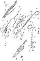
- a bipolar forceps 10 for use with open surgical proceduresincludes a mechanical forceps 20 having an end effector 24 and a disposable electrode assembly 21.
- Mechanical forceps 20includes first and second elongated shaft members 12 and 14.
- Elongated shaft member 12includes proximal and distal end portions 13 and 17, respectively, and elongated shaft member 14 includes proximal and distal end portions 15 and 19, respectively.
- Disposed at proximal end portions 13, 15 of shaft members 12, 14are handle members 16 and 18, respectively, that are configured to allow a user to effect movement of at least one of the shaft members 12 and 14 relative to the other.
- the end effector 24includes opposing jaw members 42, 44 that extend from the distal end portions 17 and 19 of shaft members 12 and 14, respectively.
- the jaw members 42, 44are movable relative to each other in response to movement of shaft members 12, 14.
- Shaft members 12 and 14are affixed to one another about a pivot 25 such that movement of shaft members 12, 14, imparts movement of the jaw members 42, 44 from a first configuration ( FIG. 9A ) wherein the jaw members 44, 42 are disposed in spaced relation relative to one another, e.g., an open configuration, to a second configuration ( FIGS. 9B and 9C ) wherein the jaw members 42, 44 cooperate to grasp tissue 150 therebetween ( FIG. 8 ), e.g., a clamping or closed configuration.
- the forceps 10may be configured such that movement of one or both of the shaft members 12, 14 causes only one of the jaw members to move with respect to the other jaw member.
- Pivot 25includes a pair of generally semi-circular shaped apertures 25a, 25b disposed therethrough and is configured to be seated in a pivot aperture 29 ( FIG. 3 ) such that pivot 25 is permitted to freely rotate within pivot aperture 29, as further detailed below.
- Each shaft member 12 and 14also includes a ratchet portion 32 and 34, respectively.
- Each ratchet 32, 34extends from the proximal end portion 13, 15 of its respective shaft member 12, 14 towards the other ratchet in a generally vertically aligned manner such that the inner facing surfaces of each ratchet 32 and 34 abut one another when the shaft members 12, 14 are approximated.
- Each ratchet 32 and 34includes a plurality of flanges 31 and 33 ( FIG. 3 ), respectively, that project from the inner facing surface of each ratchet 32 and 34 such that the ratchets 32 and 34 may interlock at one or more positions.
- Each ratchet positionholds a particular strain energy in the shaft members 12 and 14 to impart a specific closure force to the end effector 24.
- At least one of the shaft members, e.g., shaft member 12,includes a tang 99 that facilitates manipulation of forceps 20 during surgical conditions as well as facilitates attachment of electrode assembly 21 on mechanical forceps 20 as will be described in greater detail below.
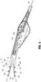
- disposable electrode assembly 21is configured to releasably couple to mechanical forceps 20, as detailed below, and is operably coupled to a housing 70 having a pair of housing halves 70a, 70b configured to matingly engage and releasably encompass at least a portion of shaft member 14.
- Housing 70also serves to house a knife 85 having a sharpened distal cutting edge 89 ( FIG. 9C ), a knife guide 86 having a longitudinal slot 87 ( FIG. 3 ) configured to receive the knife blade 85 therein, and a knife actuation mechanism 90 ( FIG. 3 ) configured to effect advancement of the knife blade 85 through a knife channel 58 ( FIG.
- each of housing half 70a, 70bmay include a plurality of cooperating mechanical interfaces disposed at various positions to effect mechanical coupling of housing halves 70a, 70b to form housing 70.
- a pair of wires 61 and 62are electrically connected to the electrodes 120 and 110, respectively, and are bundled to form a cable 28 that extends through housing 70 and terminates at a terminal connector 30 ( FIGS. 1 and 3 ) configured to mechanically and electrically couple to a suitable energy source such as an electrosurgical generator (not shown).
- a suitable energy sourcesuch as an electrosurgical generator (not shown).
- an electrosurgical generatoris the LIGASURE® Vessel Sealing Generator and the ForceTriad® Generator sold by Covidien.
- handle members 16 and 18may include a suitable mechanical interface (e.g., a wire holder) configured to releasably retain cable 28 to aid in keeping cable 28 from interfering with a surgeon's hands during operation of forceps 10.
- electrode assembly 21includes a generally circular boss member 49 configured to be seated (e.g., friction fit) within a complementary aperture 71 disposed through a distal end of housing half 70a to releasably attach electrode assembly 21 thereto. Electrode assembly 21 is bifurcated such that two prong-like members 103 and 105 extend distally therefrom to support electrodes 110 and 120, respectively. Electrode 120 includes an electrically conductive sealing surface 126 configured to conduct electrosurgical energy therethrough and an electrically insulative substrate 121 that serves to electrically insulate jaw member 42 from sealing surface 126.
- Sealing surface 126 and substrate 121are attached to one another by any suitable method of assembly such as, for example, snap-fit engagement or by overmolding substrate 121 to sealing surface 126.
- substrate 121is made from an injection molded plastic material.
- Substrate 121includes a plurality of bifurcated anchor members 122 extending therefrom that are configured to compress during insertion into a corresponding plurality of sockets 43 disposed at least partially through an inner facing surface 47 ( FIG. 3 ) of jaw member 44 and subsequently expand to releasably engage corresponding sockets 43 after insertion to couple electrode 120 to inner facing surface 47.
- Substrate 121also includes an alignment pin 124 ( FIG.
- Conductive sealing surface 126includes an extension 135 having a wire crimp 117 configured to be inserted into the distal end 106 of prong 105 of electrode assembly 21 and electrically connect to wire 61 disposed therein ( FIG. 5 ).
- electrode 110includes an electrically conductive sealing surface 116 configured to conduct electrosurgical energy therethrough and an electrically insulative substrate 111 attached thereto, as shown in FIG. 7 .
- Substrate 111includes a plurality of bifurcated anchor members 112 extending therefrom that are configured to compress during insertion into a corresponding plurality of sockets 41 disposed at least partially through an inner facing surface 45 ( FIG. 3 ) of jaw member 42 and subsequently expand to releasably engage corresponding sockets 41 after insertion to couple electrode 110 to inner facing surface 45.
- Substrate 111also includes an alignment pin 128 ( FIG.
- Sealing surface 116includes an extension 155 having a wire crimp 119 extending therefrom configured to be inserted into the distal end 104 of prong 103 of electrode assembly 21 and electrically connect to wire 62 disposed therein.
- Substrate 111includes an extension 165 extending proximally therefrom and configured to couple to extension 155 of sealing surface 116.
- the prong members 103, 105is flexible such that prong members 105 and 103 are readily moveable relative to each other.
- the electrode assembly 21is removably attached to the mechanical forceps 20 by initially moving prongs 103, 105 towards each other. While jaw members 42, 44 are in an open configuration, the electrodes 120 and 110 may be slid between opposing jaw members 44 and 42 such that anchor members 122 and 112 and guide pins 124 and 128, respectively, may be aligned with and releasably inserted into corresponding sockets 43 and 41 or apertures 65 and 67, respectively, to couple electrodes 120 and 110 with jaw members 44 and 42, respectively. Housing halves 70a, 70b may then be releasably coupled to form housing 70 to encompass at least a portion of shaft member 14 in the manner described above.
- the housing 70supports a pair of depressible activation buttons 50a, 50b that are operable by the user to actuate corresponding switches 60a, 60b, respectively, disposed within housing 70.
- switches 60a, 60bare electrically interconnected with wires 61, 62, respectively, and serve to initiate and terminate the delivery of electrosurgical energy from a suitable energy source to the end effector 24 to effect a tissue seal.
- the knife blade 85may be advanced through the knife channel 58 to transect the sealed tissue, as detailed below. However, in some examples, knife blade 85 may be advanced through the knife channel 58 before, during, or after tissue sealing.
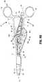
- a knife lockout mechanism 80is provided to prevent extension of the knife blade 85 into the knife channel 58 when the jaw members 42, 44 are in the open configuration, thus preventing accidental or premature transection of tissue, as detailed below.
- the knife actuation mechanism 90is operably associated with a trigger 45 having opposing handle members 45a, 45b extending from opposing sides of housing 70. Upon actuation of handle members 45a, 45b, the knife actuation mechanism 90 responds utilizing a series of inter-cooperating elements to actuate the knife blade 85 through the knife channel 58 to sever tissue grasped between jaw members 42, 44, as detailed below with reference to FIG. 9C . More specifically, the knife actuation mechanism 90 includes a first link 92 operably coupled at one end to a shaft member 47 and at an opposing end to a second link 94 by a pivot pin 92a.
- Shaft member 47extends laterally through housing 70 to operably connect handle members 45a, 45b from opposing sides of housing 70.
- the second link 94is operably coupled at one end to the first link 92 by the pivot pin 92a and at the other end to a proximal end of the knife blade 85 by a pivot pin 94a ( FIG. 9A ).
- Shaft member 14defines a longitudinal slot 14a therethrough that is configured to receive first and second links 92, 94 therein.
- First and second links 92, 94extend through longitudinal slot 14a and are free to move therethrough upon actuation of the handle members 45a, 45b, as further detailed below with reference to FIG. 9C .
- a biasing member 95(e.g., torsion spring) is disposed coaxially about at least a portion of the shaft member 47 between the first link 92 and handle member 45a.
- the biasing member 95is operably coupled at one end to a portion of the first link 92 and at the other end to a suitable mechanical interface within the housing 70 that braces or stabilizes biasing member 95 during use of the knife actuation mechanism 90.
- the biasing member 95serves to bias the trigger 45 such that subsequent to actuation of the knife blade 85 through the knife channel 58 ( FIG. 9C ), handle members 45a, 45 are biased to return to an unactuated position ( FIGS. 9A and 9B ), thereby retracting the knife blade 85 proximally to an unactuated position ( FIGS. 9A and 9B ).
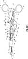
- pivot 25includes a pair of apertures 25a, 25b disposed therethrough that are configured to receive a pair of complementary raised portions 13a, 13b therein, respectively, extending from the distal end portion 17 of shaft member 12 and defining a longitudinal passageway 27 therebetween.
- Raised portions 13a, 13bextend sufficiently from the distal portion of shaft member 14 so that apertures 25a, 25b may receive raised portions 13a, 13b therein, respectively, while maintaining pivot 25 in spaced relation with the distal portion of shaft member 14 to allow the knife guide 86 to be received through passageway 27. Movement of shaft members 12, 14 relative to each other causes rotational movement of pivot 25 within pivot aperture 29.
- a knife guide 86is supported within the housing 70 between the end effector 24 and the knife actuation mechanism 90 and extends through passageway 27.
- the longitudinal slot 87 of the knife guide 86provides lateral support to the knife blade 85 and constrains side-to-side lateral motion of the knife blade 85.
- the distal knife guide 86serves to urge the knife blade 85 into a central position relative to end effector 24, thereby ensuring proper alignment of the knife blade 85 as the knife blade 85 enters the knife channel 58 ( FIG. 2 ) defined in electrodes 110, 120.
- the forceps 10includes a knife blade lockout mechanism 80 supported within the housing 70 and that serves to prevent advancement of the knife blade 85 into the knife channel 85 when the jaw members 42, 44 are in the open configuration ( FIG. 9A ).
- the knife blade lockout mechanism 80includes a safety link 81 operably coupled with a biasing member 83 (e.g., a leaf spring) and pivotally supported within the housing 70.
- a biasing member 83e.g., a leaf spring
- housing 70includes a longitudinal opening 70c that opposes shaft member 12 and exposes the knife blade lockout mechanism 80 such that upon approximation of the shaft members 12, 14 to move the jaw members 42, 44 to the closed position ( FIG. 9B ), safety link 81 is engaged by shaft member 12. Pressure applied to safety link 81 by approximation of shaft members 12, 14 operates to bias the biasing member 83 against the knife blade 85 and, in turn, rotate the safety link 81 out of engagement with the pivot pin 94a ( FIG. 9B ) such that knife blade 85 is permitted to advance distally into the knife channel 58 ( FIG. 9C ). Operation of the knife actuation mechanism 90, the knife lockout mechanism 80, and actuation of the knife blade 85 is further detailed below with reference to FIGS. 9A-9C .
- the tissue seal thickness and tissue seal effectivenessmay be influenced by the pressure applied to tissue between jaw members 44, 42 and the gap distance between the opposing electrodes 110 and 120 ( FIG. 5 ) during tissue sealing.
- a separation or gap distance "G"may be maintained between the sealing surfaces 116, 126 by an array of stop members 54 ( FIG. 2 ) disposed on one or both of sealing surfaces 116, 126 (only shown disposed on sealing surface 126 for purposes of illustration).
- the stop members 54contact the sealing surface on the opposing jaw member and prohibit further approximation of the sealing surfaces 116, 126.
- an appropriate gap distance of about (0.0254 mm) 0.001 inches to about (0.254 mm) 0.010 inches and, desirably, between about (0.051 mm) 0.002 and about (0.127 mm) 0.005 inchesmay be provided.
- the stop members 54are constructed of an electrically non-conductive plastic or other material molded onto the sealing surfaces 116, 126, e.g., by a process such as overmolding or injection molding. In other embodiments, the stop members 54 are constructed of a heat-resistant ceramic deposited onto sealing surfaces 116, 126.
- FIG. 8shows the bipolar forceps 10 during use wherein the shaft members 12 and 14 are approximated to apply clamping force to tissue 150 and to effect a tissue seal. Once sealed, tissue 150 may be cut along the tissue seal through actuation of the knife blade 85, as detailed below with reference to FIGS. 9A-9C .
- the performance of forceps 10may be tested using a virtual tissue vessel. More specifically, the user may place a virtual tissue vessel between sealing surfaces 116, 126 and apply a clamping force to the vessel.
- the virtual tissue vesselmay be, for example, any suitable plastic having impedance.
- the usermay seal the virtual tissue vessel using electrosurgical energy from a suitable electrosurgical generator, e.g., LIGASURE® Vessel Sealing Generator and the ForceTriad® Generator sold by Covidien.
- the usermay also actuate the handle members 45a, 45b to advance the knife blade 85 through the knife channel 58 to cut the sealed virtual tissue vessel.
- the electrosurgical generatormay be configured to automatically run a test procedure that serves to sense the applied clamping force, the gap distance between the opposing electrodes 110, 120, and/or the impedance of the virtual tissue vessel before, during, or after sealing. From this sensed information, the electrosurgical generator may serve to verify that the forceps 10 is in proper working condition (e.g., proper clamping force, gap distance, etc.) following assembly of the electrode assembly 21 to the mechanical forceps 20 and prior to use of the assembled forceps 10 in a vessel sealing procedure.
- proper working conditione.g., proper clamping force, gap distance, etc.
- a sequence of motionsmay be initiated by moving the shaft members 12, 14 in order to close the jaw members 42, 44, and by rotating the handle members 45a, 45b to induce the knife actuation mechanism 90 to translate the knife blade 85 through the knife channel 58.
- shaft members 12, 14are in the open configuration and the handle members 45a, 45b are in an un-actuated position as depicted in FIG. 9A .
- This arrangement of shaft members 12, 14 and handle members 45a, 45bsustains the end effector 24 in the open configuration wherein the jaw members 42, 44 are substantially spaced from one another, and the knife blade 85 is in a retracted or proximal position with respect to the jaw members 42, 44.
- the jaw members 42, 44may be moved from the open configuration of FIG. 9A to the closed configuration depicted in FIG. 9B .
- shaft member 12engages safety link 81.
- shaft member 12applies a force on the safety link 81 that causes biasing member 83 to flex against the bias of knife blade 85, thereby inducing rotation of the safety link 81 in the direction depicted by rotational arrow A3 in FIG. 9B .
- Rotation of safety link 81 in the direction of rotational arrow A3operates to move the safety link 81 out of engagement with pivot pin 94a as shown in FIG. 9C .
- handle members 45a, 45bmay be selectively moved from the unactuated configuration of FIGS. 9A and 9B to the actuated position of FIG. 9C to advance the knife blade 85 distally through knife channel 58. More specifically, as handle members 45a, 45b rotate in the general proximal direction, depicted by rotational arrow A4, to the actuated configuration depicted in FIG. 9C , the first link 92 imparts a rotational force on second link 94, thereby causing second link 94 to rotate about pivot pin 94a and move in a general distal direction to advance knife blade 85 distally into the knife channel 58.
- the knife actuation mechanism 90may be positioned relative to shaft member 14 different than the depiction of knife actuation mechanism 90 in FIG. 3 .
- knife actuation mechanism 90 depicted in FIG. 3is disposed substantially between shaft members 14 and 12
- knife actuation mechanism 90may be disposed on an opposing side of shaft member 14 such that shaft member 14 is disposed between knife actuation mechanism 90 and shaft member 12.
- shaft members 12, 14may be alternatively configured to allow knife blade 85 to advance through longitudinal passageway 27 defined by raised portions 13a, 13b (e.g., via knife guide 86) and into knife channel 58.
- distal ends 17, 19 of shaft members 12, 14, respectivelymay be configured in various interlocking relationships (e.g., a lock-box configuration) that facilitate the knife 85 entering the knife channel 58 in various orientations relative to shaft members 12, 14 and/or knife channel 58.
- various interlocking relationshipse.g., a lock-box configuration
Landscapes
- Health & Medical Sciences (AREA)
- Surgery (AREA)
- Engineering & Computer Science (AREA)
- Life Sciences & Earth Sciences (AREA)
- Biomedical Technology (AREA)
- Otolaryngology (AREA)
- Nuclear Medicine, Radiotherapy & Molecular Imaging (AREA)
- Plasma & Fusion (AREA)
- Physics & Mathematics (AREA)
- Heart & Thoracic Surgery (AREA)
- Medical Informatics (AREA)
- Molecular Biology (AREA)
- Animal Behavior & Ethology (AREA)
- General Health & Medical Sciences (AREA)
- Public Health (AREA)
- Veterinary Medicine (AREA)
- Surgical Instruments (AREA)
Description
- The present disclosure relates to forceps used for open surgical procedures. More particularly, the present disclosure relates to a bipolar forceps for treating tissue that is capable of sealing and cutting tissue.
- A hemostat or forceps is a simple plier-like tool which uses mechanical action between its jaws to constrict vessels and is commonly used in open surgical procedures to grasp, dissect and/or clamp tissue. Electrosurgical forceps utilize both mechanical clamping action and electrical energy to effect hemostasis by heating the tissue and blood vessels to coagulate, cauterize and/or seal tissue.
- Certain surgical procedures require sealing and cutting blood vessels or vascular tissue. Several journal articles have disclosed methods for sealing small blood vessels using electrosurgery. An article entitledStudies on Coagulation and the Development of an Automatic Computerized Bipolar Coagulator, J. Neurosurg., Volume 75, July 1991, describes a bipolar coagulator which is used to seal small blood vessels. The article states that it is not possible to safely coagulate arteries with a diameter larger than 2 to 2.5 mm. A second article is entitledAutomatically Controlled Bipolar Electrocoagulation - "COA-COMP", Neurosurg. Rev. (1984), pp. 187-190, describes a method for terminating electrosurgical power to the vessel so that charring of the vessel walls can be avoided.
- By utilizing an electrosurgical forceps, a surgeon can either cauterize, coagulate/desiccate, reduce or slow bleeding and/or seal vessels by controlling the intensity, frequency and duration of the electrosurgical energy applied to the tissue. Generally, the electrical configuration of electrosurgical forceps can be categorized in two classifications: 1) monopolar electrosurgical forceps; and 2) bipolar electrosurgical forceps.
- Monopolar forceps utilize one active electrode associated with the clamping end effector and a remote patient return electrode or pad which is typically attached externally to the patient. When the electrosurgical energy is applied, the energy travels from the active electrode, to the surgical site, through the patient and to the return electrode.
- Bipolar electrosurgical forceps utilize two generally opposing electrodes which are disposed on the inner opposing surfaces of the end effectors and which are both electrically coupled to an electrosurgical generator. Each electrode is charged to a different electric potential. Since tissue is a conductor of electrical energy, when the effectors are utilized to grasp tissue therebetween, the electrical energy can be selectively transferred through the tissue.
US2011238067 discloses mechanical forceps with a disposable housing comprising electrodes for the jaws and a cutting blade. - The present disclosure relates to forceps used for open surgical procedures. More particularly, the present disclosure relates to a bipolar forceps for treating tissue that is capable of sealing and cutting tissue, according to independent claim 1. Preferred embodiments are disclosed in the dependent claims.
- As is traditional, the term "distal" refers herein to an end of the apparatus that is farther from an operator, and the term "proximal" refers herein to the end of the electrosurgical forceps that is closer to the operator.
- The bipolar forceps includes a mechanical forceps including first and second shafts. A jaw member extends from a distal end of each shaft. A handle is disposed at a proximal end of each shaft for effecting movement of the jaw members relative to one another about a pivot from a first position wherein the jaw members are disposed in spaced relation relative to one another to a second position wherein the jaw members cooperate to grasp tissue. A disposable housing is configured to releasably couple to one or both of the shafts. An electrode assembly is associated with the disposable housing and has a first electrode releasably coupleable to the jaw member of the first shaft and a second electrode releasably coupleable to the jaw member of the second shaft. Each electrode is adapted to connect to a source of electrosurgical energy to allow selective conduction of electrosurgical energy through tissue. One or both of the electrodes includes a knife channel defined along its length. The knife channel is configured to receive a knife blade therethrough to cut tissue grasped between the jaw members. An actuation mechanism is at least partially disposed within the housing and configured to selectively advance the knife blade through the knife channel to cut tissue.
- Additionally or alternatively, the bipolar forceps may also include a knife lockout mechanism configured to prohibit advancement of the knife blade into the knife channel when the jaw members are in the first position.
- Additionally or alternatively, the knife lockout mechanism may move from a first position wherein the knife lockout mechanism engages the actuation mechanism when the jaw members are in the first position to a second position wherein the knife lockout mechanism disengages the actuation mechanism when the jaw members are in the second position to permit selective advancement of the knife blade through the knife channel.
- Additionally or alternatively, at least one of the shafts may be configured to engage the knife lockout mechanism upon movement of the jaw members to the second position and move the knife lockout mechanism out of engagement with the actuation mechanism to permit advancement of the knife blade through the knife channel.
- Additionally or alternatively, the bipolar forceps may also include at least one depressible button supported by the housing configured to selectively deliver electrosurgical energy to the electrodes.
- Additionally or alternatively, the pivot may define a longitudinal slot therethrough and the knife blade may be configured to move within the longitudinal slot upon translation thereof.
- Additionally or alternatively, the bipolar forceps may also include at least one handle member extending from the housing. The at least one handle member may be operably coupled to the actuation mechanism and configured to effect advancement of the knife blade through the knife channel.
- Additionally or alternatively, each of the electrodes may include an electrically conductive sealing surface and an insulating substrate coupled thereto.
- Additionally or alternatively, each of the electrodes may include at least one mechanical interface configured to complement a corresponding mechanical interface on one of the jaw members to releasably couple the electrode to the jaw member.
- Additionally or alternatively, the actuation mechanism may include a biasing member configured to bias the actuation mechanism to an unactuated position.
- Additionally or alternatively, the bipolar forceps may also include a knife guide supported in the housing and having a longitudinal slot defined therethrough that receives the knife blade therein to align the knife blade with the knife channel.
- According to another aspect of the present disclosure, a bipolar forceps is provided. The bipolar forceps includes a mechanical forceps including first and second shafts each having a jaw member extending from its distal end. A handle is disposed at a proximal end of each shaft for effecting movement of the jaw members relative to one another about a pivot from a first position wherein the jaw members are disposed in spaced relation relative to one another to a second position wherein the jaw members cooperate to grasp tissue. A disposable housing has opposing halves configured to releasably couple to each other to at least partially encompass one or both of the shafts. An electrode assembly is associated with the disposable housing and has a first electrode releasably coupleable to the jaw member of the first shaft and a second electrode releasably coupleable to the jaw member of the second shaft. Each electrode is adapted to connect to a source of electrosurgical energy to allow selective conduction of electrosurgical energy through tissue held therebetween. At least one of the electrodes includes a knife channel defined along a length thereof, the knife channel configured to receive a knife blade therethrough to cut tissue grasped between the jaw members. An actuation mechanism is at least partially disposed within the housing and is configured to selectively advance the knife blade through the knife channel to cut tissue. A knife lockout mechanism is configured to move from a first position wherein the knife lockout mechanism engages the actuation mechanism to prohibit advancement of the knife blade through the knife channel when the jaw members are in the first position to a second position wherein the knife lockout mechanism disengages the actuation mechanism when the jaw members are in the second position to permit advancement of the knife blade through the knife channel.
- Additionally or alternatively, at least one of the shafts may be configured to engage the knife lockout mechanism upon movement of the jaw members to the second position and move the knife lockout mechanism out of engagement with the actuation mechanism and permit advancement of the knife blade through the knife channel.
- Additionally or alternatively, the pivot may define a longitudinal slot therethrough and the knife blade may be configured to advance through the longitudinal slot upon translation thereof.
- Additionally or alternatively, the bipolar forceps may also include a knife guide supported in the housing and having a longitudinal slot defined therethrough that receives the knife blade therein to align the knife blade with the knife channel.
- Additionally or alternatively, the bipolar forceps may also include at least one handle member configured to effect advancement of the knife blade through the knife channel. The at least one handle member may extend from the housing and may be operably coupled to the actuation mechanism.
- According to another aspect of the present disclosure, a bipolar forceps is provided. The bipolar forceps includes a mechanical forceps including first and second shafts each having a jaw member extending from its distal end. A handle is disposed at a proximal end of each shaft for effecting movement of the jaw members relative to one another about a pivot from a first position wherein the jaw members are disposed in spaced relation relative to one another to a second position wherein the jaw members cooperate to grasp tissue therebetween. A disposable housing is configured to be releasably coupled to at least one of the shafts. An electrode assembly is configured to releasably couple to the jaw members and is adapted to connect to a source of electrosurgical energy to allow selective conduction of electrosurgical energy through tissue held between the jaw members. At least one of the jaw members includes a knife channel defined along its length. The knife channel is configured to receive a knife blade therethrough to cut tissue grasped between the jaw members. A knife guide is supported in the housing and has a longitudinal slot defined therethrough that receives the knife blade therein to align the knife blade with the knife channel. An actuation mechanism is at least partially disposed within the housing and is configured to selectively advance the knife blade through the knife channel to cut tissue. At least one handle member extends from the housing. The at least one handle member is operably coupled to the actuation mechanism and is configured to effect advancement of the knife blade through the knife channel. A knife lockout mechanism is configured to be engaged by at least one of the shaft members and move the knife lockout mechanism from a first position wherein the knife lockout mechanism engages the actuation mechanism to prohibit advancement of the knife blade into the knife channel when the jaw members are in the first position to a second position wherein the knife lockout mechanism disengages the actuation mechanism when the jaw members are in the second position to permit selective advancement of the knife blade through the knife channel.
- Additionally or alternatively, the knife guide may extend through a longitudinal slot defined through the pivot.
- Additionally or alternatively, the at least one handle member may be moveable from a first position wherein the knife blade is disposed within the housing to a second position wherein the knife blade is advanced through the knife channel.
- Additionally or alternatively, the actuating mechanism may include a biasing member configured to bias the at least one movable handle from the second position to the first position.
- Various embodiments of the subject instrument are described herein with reference to the drawings wherein:
FIG. 1 is a perspective view of a bipolar forceps according to an embodiment of the present disclosure including a mechanical forceps, a disposable housing, and a disposable electrode assembly;FIG. 2 is an enlarged, perspective view of a distal end of the bipolar forceps ofFIG. 1 ;FIG. 3 is a perspective view of the bipolar forceps ofFIG. 1 with parts separated;FIG. 4 is an enlarged, internal side view of the disposable housing and the disposable electrode assembly ofFIG. 1 with parts partially removed;FIG. 5 is a greatly-enlarged, perspective view of the disposable electrode assembly ofFIG. 1 ;FIGS. 6 and 7 are greatly-enlarged perspective views of electrodes of the disposable electrode assembly ofFIG. 1 with parts separated;FIG. 8 is a perspective view of the bipolar forceps ofFIG. 1 grasping tissue to effect a tissue seal; andFIGS. 9A-9C are generally internal, side views of the bipolar forceps ofFIG. 1 depicting a sequence of motions to illustrate operation of the bipolar forceps.- Referring initially to
FIGS. 1-3 , abipolar forceps 10 for use with open surgical procedures includes amechanical forceps 20 having anend effector 24 and adisposable electrode assembly 21.Mechanical forceps 20 includes first and secondelongated shaft members Elongated shaft member 12 includes proximal anddistal end portions elongated shaft member 14 includes proximal anddistal end portions proximal end portions shaft members handle members shaft members end effector 24 includes opposingjaw members distal end portions shaft members jaw members shaft members Shaft members pivot 25 such that movement ofshaft members jaw members FIG. 9A ) wherein thejaw members FIGS. 9B and9C ) wherein thejaw members tissue 150 therebetween (FIG. 8 ), e.g., a clamping or closed configuration. Theforceps 10 may be configured such that movement of one or both of theshaft members Pivot 25 includes a pair of generally semi-circular shapedapertures FIG. 3 ) such thatpivot 25 is permitted to freely rotate withinpivot aperture 29, as further detailed below.- Each
shaft member ratchet portion ratchet proximal end portion respective shaft member ratchet shaft members ratchet flanges 31 and 33 (FIG. 3 ), respectively, that project from the inner facing surface of eachratchet ratchets shaft members end effector 24. At least one of the shaft members, e.g.,shaft member 12, includes atang 99 that facilitates manipulation offorceps 20 during surgical conditions as well as facilitates attachment ofelectrode assembly 21 onmechanical forceps 20 as will be described in greater detail below. - Referring to
FIGS. 2 and3 ,disposable electrode assembly 21 is configured to releasably couple tomechanical forceps 20, as detailed below, and is operably coupled to ahousing 70 having a pair ofhousing halves shaft member 14.Housing 70 also serves to house aknife 85 having a sharpened distal cutting edge 89 (FIG. 9C ), aknife guide 86 having a longitudinal slot 87 (FIG. 3 ) configured to receive theknife blade 85 therein, and a knife actuation mechanism 90 (FIG. 3 ) configured to effect advancement of theknife blade 85 through a knife channel 58 (FIG. 2 ) defined in one or bothelectrodes housing half housing halves housing 70. - As shown in
FIGS. 4 and5 , a pair ofwires electrodes cable 28 that extends throughhousing 70 and terminates at a terminal connector 30 (FIGS. 1 and3 ) configured to mechanically and electrically couple to a suitable energy source such as an electrosurgical generator (not shown). One example of an electrosurgical generator is the LIGASURE® Vessel Sealing Generator and the ForceTriad® Generator sold by Covidien. One or both ofhandle members cable 28 to aid in keepingcable 28 from interfering with a surgeon's hands during operation offorceps 10. - Referring now to
FIGS. 3-7 ,electrode assembly 21 includes a generallycircular boss member 49 configured to be seated (e.g., friction fit) within acomplementary aperture 71 disposed through a distal end ofhousing half 70a to releasably attachelectrode assembly 21 thereto.Electrode assembly 21 is bifurcated such that two prong-like members electrodes Electrode 120 includes an electricallyconductive sealing surface 126 configured to conduct electrosurgical energy therethrough and an electricallyinsulative substrate 121 that serves to electrically insulatejaw member 42 from sealingsurface 126. Sealingsurface 126 andsubstrate 121 are attached to one another by any suitable method of assembly such as, for example, snap-fit engagement or byovermolding substrate 121 to sealingsurface 126. In some examples,substrate 121 is made from an injection molded plastic material.Substrate 121 includes a plurality ofbifurcated anchor members 122 extending therefrom that are configured to compress during insertion into a corresponding plurality ofsockets 43 disposed at least partially through an inner facing surface 47 (FIG. 3 ) ofjaw member 44 and subsequently expand to releasably engage correspondingsockets 43 after insertion tocouple electrode 120 to inner facingsurface 47.Substrate 121 also includes an alignment pin 124 (FIG. 6 ) that is configured to engage anaperture 65 disposed at least partially through inner facingsurface 47 ofjaw member 44 to ensure proper alignment ofelectrode 120 withjaw member 44 during assembly.Conductive sealing surface 126 includes anextension 135 having awire crimp 117 configured to be inserted into thedistal end 106 ofprong 105 ofelectrode assembly 21 and electrically connect to wire 61 disposed therein (FIG. 5 ). - Substantially as described above with respect to
electrode 120,electrode 110 includes an electricallyconductive sealing surface 116 configured to conduct electrosurgical energy therethrough and an electricallyinsulative substrate 111 attached thereto, as shown inFIG. 7 .Substrate 111 includes a plurality ofbifurcated anchor members 112 extending therefrom that are configured to compress during insertion into a corresponding plurality ofsockets 41 disposed at least partially through an inner facing surface 45 (FIG. 3 ) ofjaw member 42 and subsequently expand to releasably engage correspondingsockets 41 after insertion tocouple electrode 110 to inner facingsurface 45.Substrate 111 also includes an alignment pin 128 (FIG. 4 ) that is configured to engage anaperture 67 disposed at least partially through inner facingsurface 45 ofjaw member 42 to ensure proper alignment ofelectrode 110 withjaw member 42 during assembly. Sealingsurface 116 includes anextension 155 having awire crimp 119 extending therefrom configured to be inserted into thedistal end 104 ofprong 103 ofelectrode assembly 21 and electrically connect to wire 62 disposed therein.Substrate 111 includes anextension 165 extending proximally therefrom and configured to couple toextension 155 of sealingsurface 116. - Referring to
FIG. 4 , at least one of theprong members prong members electrode assembly 21 is removably attached to themechanical forceps 20 by initially movingprongs jaw members electrodes jaw members anchor members pins corresponding sockets apertures electrodes jaw members Housing halves housing 70 to encompass at least a portion ofshaft member 14 in the manner described above. - To electrically control the
end effector 24, thehousing 70 supports a pair ofdepressible activation buttons corresponding switches housing 70. Although not explicitly shown,switches wires end effector 24 to effect a tissue seal. - Once a tissue seal is established, the
knife blade 85 may be advanced through theknife channel 58 to transect the sealed tissue, as detailed below. However, in some examples,knife blade 85 may be advanced through theknife channel 58 before, during, or after tissue sealing. In the invention, aknife lockout mechanism 80 is provided to prevent extension of theknife blade 85 into theknife channel 58 when thejaw members - With reference to
FIG. 3 , theknife actuation mechanism 90 is operably associated with atrigger 45 having opposing handlemembers housing 70. Upon actuation ofhandle members knife actuation mechanism 90 responds utilizing a series of inter-cooperating elements to actuate theknife blade 85 through theknife channel 58 to sever tissue grasped betweenjaw members FIG. 9C . More specifically, theknife actuation mechanism 90 includes afirst link 92 operably coupled at one end to ashaft member 47 and at an opposing end to asecond link 94 by apivot pin 92a.Shaft member 47 extends laterally throughhousing 70 to operably connecthandle members housing 70. Thesecond link 94 is operably coupled at one end to thefirst link 92 by thepivot pin 92a and at the other end to a proximal end of theknife blade 85 by apivot pin 94a (FIG. 9A ).Shaft member 14 defines alongitudinal slot 14a therethrough that is configured to receive first andsecond links second links longitudinal slot 14a and are free to move therethrough upon actuation of thehandle members FIG. 9C . - A biasing member 95 (e.g., torsion spring) is disposed coaxially about at least a portion of the
shaft member 47 between thefirst link 92 and handlemember 45a. The biasingmember 95 is operably coupled at one end to a portion of thefirst link 92 and at the other end to a suitable mechanical interface within thehousing 70 that braces or stabilizes biasingmember 95 during use of theknife actuation mechanism 90. The biasingmember 95 serves to bias thetrigger 45 such that subsequent to actuation of theknife blade 85 through the knife channel 58 (FIG. 9C ), handlemembers FIGS. 9A and9B ), thereby retracting theknife blade 85 proximally to an unactuated position (FIGS. 9A and9B ). - With reference to
FIG. 3 ,pivot 25 includes a pair ofapertures portions distal end portion 17 ofshaft member 12 and defining alongitudinal passageway 27 therebetween. Raisedportions shaft member 14 so thatapertures portions pivot 25 in spaced relation with the distal portion ofshaft member 14 to allow theknife guide 86 to be received throughpassageway 27. Movement ofshaft members pivot 25 withinpivot aperture 29. - A
knife guide 86 is supported within thehousing 70 between theend effector 24 and theknife actuation mechanism 90 and extends throughpassageway 27. Thelongitudinal slot 87 of theknife guide 86 provides lateral support to theknife blade 85 and constrains side-to-side lateral motion of theknife blade 85. Thus, thedistal knife guide 86 serves to urge theknife blade 85 into a central position relative to endeffector 24, thereby ensuring proper alignment of theknife blade 85 as theknife blade 85 enters the knife channel 58 (FIG. 2 ) defined inelectrodes - In the invention, the
forceps 10 includes a knifeblade lockout mechanism 80 supported within thehousing 70 and that serves to prevent advancement of theknife blade 85 into theknife channel 85 when thejaw members FIG. 9A ). With reference toFIG. 3 , the knifeblade lockout mechanism 80 includes asafety link 81 operably coupled with a biasing member 83 (e.g., a leaf spring) and pivotally supported within thehousing 70. In the open configuration ofjaw members knife blade 85 is in an unactuated position (FIG. 9A and9B ) and thesafety link 81 is engaged withpivot pin 94a (FIG. 9A ) such that distal advancement ofknife blade 85 is prohibited. As shown inFIG. 1 ,housing 70 includes alongitudinal opening 70c that opposesshaft member 12 and exposes the knifeblade lockout mechanism 80 such that upon approximation of theshaft members jaw members FIG. 9B ),safety link 81 is engaged byshaft member 12. Pressure applied tosafety link 81 by approximation ofshaft members member 83 against theknife blade 85 and, in turn, rotate thesafety link 81 out of engagement with thepivot pin 94a (FIG. 9B ) such thatknife blade 85 is permitted to advance distally into the knife channel 58 (FIG. 9C ). Operation of theknife actuation mechanism 90, theknife lockout mechanism 80, and actuation of theknife blade 85 is further detailed below with reference toFIGS. 9A-9C . - The tissue seal thickness and tissue seal effectiveness may be influenced by the pressure applied to tissue between
jaw members electrodes 110 and 120 (FIG. 5 ) during tissue sealing. In the closed configuration, a separation or gap distance "G" may be maintained between the sealingsurfaces FIG. 2 ) disposed on one or both of sealingsurfaces 116, 126 (only shown disposed on sealingsurface 126 for purposes of illustration). Thestop members 54 contact the sealing surface on the opposing jaw member and prohibit further approximation of the sealing surfaces 116, 126. In some examples, to provide an effective tissue seal, an appropriate gap distance of about (0.0254 mm) 0.001 inches to about (0.254 mm) 0.010 inches and, desirably, between about (0.051 mm) 0.002 and about (0.127 mm) 0.005 inches may be provided. In some examples, thestop members 54 are constructed of an electrically non-conductive plastic or other material molded onto the sealing surfaces 116, 126, e.g., by a process such as overmolding or injection molding. In other embodiments, thestop members 54 are constructed of a heat-resistant ceramic deposited onto sealingsurfaces FIG. 8 shows thebipolar forceps 10 during use wherein theshaft members tissue 150 and to effect a tissue seal. Once sealed,tissue 150 may be cut along the tissue seal through actuation of theknife blade 85, as detailed below with reference toFIGS. 9A-9C .- In some examples, the performance of
forceps 10 may be tested using a virtual tissue vessel. More specifically, the user may place a virtual tissue vessel between sealingsurfaces handle members knife blade 85 through theknife channel 58 to cut the sealed virtual tissue vessel. In this scenario, the electrosurgical generator may be configured to automatically run a test procedure that serves to sense the applied clamping force, the gap distance between the opposingelectrodes forceps 10 is in proper working condition (e.g., proper clamping force, gap distance, etc.) following assembly of theelectrode assembly 21 to themechanical forceps 20 and prior to use of the assembledforceps 10 in a vessel sealing procedure. - Referring now to
FIGS. 9A ,9B , and9C , a sequence of motions may be initiated by moving theshaft members jaw members handle members knife actuation mechanism 90 to translate theknife blade 85 through theknife channel 58. Initially,shaft members handle members FIG. 9A . This arrangement ofshaft members members end effector 24 in the open configuration wherein thejaw members knife blade 85 is in a retracted or proximal position with respect to thejaw members handle members FIGS. 9A and9B is actively maintained by the influence of the biasingmember 95 on thetrigger 45. Whenjaw members FIG. 9A ,safety link 81 is engaged withpivot pin 94a such that rotational motion of thehandle members FIG. 9C ) is prohibited so thatknife blade 85 is prohibited from advancing intoknife channel 58. - The
jaw members FIG. 9A to the closed configuration depicted inFIG. 9B . As theshaft members pivot 25 in the directions of arrows A1 and A2 (FIG. 9B ), respectively,shaft member 12 engagessafety link 81. As theshaft members pivot 25 in the directions of arrows A1 and A2, respectively,shaft member 12 applies a force on thesafety link 81 that causes biasingmember 83 to flex against the bias ofknife blade 85, thereby inducing rotation of thesafety link 81 in the direction depicted by rotational arrow A3 inFIG. 9B . Rotation ofsafety link 81 in the direction of rotational arrow A3 operates to move thesafety link 81 out of engagement withpivot pin 94a as shown inFIG. 9C . - Upon movement of the
safety link 81 out of engagement with thepivot pin 94a, handlemembers FIGS. 9A and9B to the actuated position ofFIG. 9C to advance theknife blade 85 distally throughknife channel 58. More specifically, ashandle members FIG. 9C , thefirst link 92 imparts a rotational force onsecond link 94, thereby causingsecond link 94 to rotate aboutpivot pin 94a and move in a general distal direction to advanceknife blade 85 distally into theknife channel 58. - In some examples the
knife actuation mechanism 90 may be positioned relative toshaft member 14 different than the depiction ofknife actuation mechanism 90 inFIG. 3 . For example, if theknife actuation mechanism 90 depicted inFIG. 3 is disposed substantially betweenshaft members knife actuation mechanism 90 may be disposed on an opposing side ofshaft member 14 such thatshaft member 14 is disposed betweenknife actuation mechanism 90 andshaft member 12. In this scenario,shaft members knife blade 85 to advance throughlongitudinal passageway 27 defined by raisedportions knife channel 58. For example, the distal ends 17, 19 ofshaft members knife 85 entering theknife channel 58 in various orientations relative toshaft members knife channel 58. - While several embodiments of the disclosure have been shown in the drawings, it is not intended that the disclosure be limited thereto, as it is intended that the disclosure be as broad in scope as the art will allow and that the specification be read likewise. Therefore, the above description should not be construed as limiting, but merely as examples of particular embodiments. Those skilled in the art will envision other modifications within the scope of the claims appended hereto.
- Although the foregoing disclosure has been described in some detail by way of illustration and example, for purposes of clarity or understanding, it will be obvious that certain changes and modifications may be practiced within the scope of the appended claims.
Claims (11)
- A bipolar forceps (10), comprising:a mechanical forceps (20) including first and second shafts (12, 14) each having a jaw member (42, 44) extending from a distal end (17, 19) thereof and a handle (16, 18) disposed at a proximal end (13, 15) thereof for effecting movement of the jaw members relative to one another about a pivot (25) from a first position wherein the jaw members are disposed in spaced relation relative to one another to a second position wherein the jaw members cooperate to grasp tissue therebetween;a disposable housing (70) comprising halves (70a, 70b) configured to matingly engage and to releasably encompass at least a portion of at least one of the shafts;an electrode assembly (21) associated with the disposable housing and having a first electrode (110) releasably coupleable to the jaw member of the first shaft and a second electrode (120) releasably coupleable to the jaw member of the second shaft, each electrode adapted to connect to a source of electro surgical energy to allow selective conduction of electrosurgical energy through tissue held therebetween;at least one of the electrodes including a knife channel (58) defined along a length thereof, the knife channel configured to receive a knife blade (85) therethrough to cut tissue grasped between the jaw members;an actuation mechanism (90) at least partially disposed within the housing and configured to selectively advance the knife blade through the knife channel to cut tissue; anda knife lockout mechanism (80) configured to prohibit advancement of the knife blade into the knife channel when the jaw members are in the first position,characterised by further comprising a knife guide (86) supported in the housing (70) and having a longitudinal slot (87) defined therethrough that receives the knife blade (85) therein to align the knife blade with the knife channel (58), wherein the knife guide (86) extends through a longitudinal slot (27) defined through the pivot (25).
- The bipolar forceps (10) according to claim 1, wherein the knife lockout mechanism (80) moves from a first position wherein the knife lockout mechanism engages the actuation mechanism (90) when the jaw members (42, 44) are in the first position to a second position wherein the knife lockout mechanism disengages the actuation mechanism when the jaw members are in the second position to permit selective advancement of the knife blade (85) through the knife channel (58).
- The bipolar forceps (10) according to claim 1, wherein at least one of the shafts (12, 14) is configured to engage the knife lockout mechanism (80) upon movement of the jaw members (42, 44) to the second position and move the knife lockout mechanism out of engagement with the actuation mechanism (90) to permit advancement of the knife blade (85) through the knife channel (58).
- The bipolar forceps (10) according to any preceding claim, further comprising at least one depressible button (50a, 50b) supported by the housing (70) configured to selectively deliver electrosurgical energy to the electrodes (110, 120).
- The bipolar forceps (10) according to any preceding claim, wherein the knife blade (85) is configured to move within the longitudinal slot (27) defined through the pivot (25) upon translation thereof.
- The bipolar forceps (10) according to any preceding claim, further comprising at least one handle member (45a, 45b) configured to effect advancement of the knife blade (85) through the knife channel (58), the at least one handle member extending from the housing (70) and operably coupled to the actuation mechanism (90).
- The bipolar forceps (10) according to any preceding claim, wherein each of the electrodes (110, 120) includes an electrically conductive sealing surface (116, 126) and an insulating substrate (111, 121) coupled thereto.
- The bipolar forceps (10) according to any preceding claim, wherein each of the electrodes (110, 120) includes at least one mechanical interface (112, 122) configured to complement a corresponding mechanical interface (41, 43) on one of the jaw members (42, 44) to releasably couple the electrode to the jaw member.
- The bipolar forceps (10) according to any preceding claim, wherein the actuation mechanism (90) includes a biasing member (95) configured to bias the actuation mechanism to an unactuated position.
- The bipolar forceps (10) according to any preceding claim, the knife lockout mechanism (80) including a safety link (81) operably coupled with a biasing member (83) and pivotally supported within the disposable housing (70), wherein the safety link is configured to engage with a pivot pin (94a) of the actuation mechanism (90) to prohibit advancement of the knife blade (85) into the knife channel (58) when the jaw members (42, 44) are in the first position.
- The bipolar forceps (10) according to claim 10, wherein at least one of the shafts (12, 14) is configured to engage the safety link (81) upon movement of the jaw members (42, 44) to the second position and move the safety link out of engagement with the pivot pin (94a) to permit advancement of the knife blade (85) through the knife channel (58).
Applications Claiming Priority (1)
| Application Number | Priority Date | Filing Date | Title |
|---|---|---|---|
| PCT/CN2013/080953WO2015017994A1 (en) | 2013-08-07 | 2013-08-07 | Bipolar surgical instrument |
Publications (3)
| Publication Number | Publication Date |
|---|---|
| EP3030179A1 EP3030179A1 (en) | 2016-06-15 |
| EP3030179A4 EP3030179A4 (en) | 2017-03-29 |
| EP3030179B1true EP3030179B1 (en) | 2019-05-08 |
Family
ID=52460498
Family Applications (1)
| Application Number | Title | Priority Date | Filing Date |
|---|---|---|---|
| EP13891305.8AActiveEP3030179B1 (en) | 2013-08-07 | 2013-08-07 | Bipolar surgical instrument |
Country Status (6)
| Country | Link |
|---|---|
| US (2) | US10499975B2 (en) |
| EP (1) | EP3030179B1 (en) |
| KR (1) | KR102128705B1 (en) |
| AU (1) | AU2013377234B2 (en) |
| CA (1) | CA2918484C (en) |
| WO (1) | WO2015017994A1 (en) |
Families Citing this family (7)
| Publication number | Priority date | Publication date | Assignee | Title |
|---|---|---|---|---|
| US10499975B2 (en) | 2013-08-07 | 2019-12-10 | Covidien Lp | Bipolar surgical instrument |
| US10245057B2 (en) | 2015-10-28 | 2019-04-02 | Covidien Lp | Surgical instruments including knife assemblies with reducible cutting height |
| US10426543B2 (en) | 2016-01-23 | 2019-10-01 | Covidien Lp | Knife trigger for vessel sealer |
| US10653475B2 (en) | 2017-06-08 | 2020-05-19 | Covidien Lp | Knife lockout for electrosurgical forceps |
| KR102316810B1 (en)* | 2019-06-17 | 2021-10-25 | 주식회사 청우메디칼 | High Frequency Wave Type of a Cutting Device for a Laparoscopic Surgery |
| PL3815642T3 (en)* | 2019-10-28 | 2023-09-25 | Erbe Elektromedizin Gmbh | Blade cartridge and sealing instrument |
| KR102450610B1 (en)* | 2020-09-14 | 2022-10-04 | 사회복지법인 삼성생명공익재단 | A Ferromagnetic Electrode Type of a Surgical Device |
Citations (2)
| Publication number | Priority date | Publication date | Assignee | Title |
|---|---|---|---|---|
| US20040236325A1 (en)* | 2001-04-06 | 2004-11-25 | Tetzlaff Philip M. | Vesel sealing forceps with disposable electrodes |
| US20110238067A1 (en)* | 2003-11-19 | 2011-09-29 | Moses Michael C | Open vessel sealing instrument with cutting mechanism |
Family Cites Families (213)
| Publication number | Priority date | Publication date | Assignee | Title |
|---|---|---|---|---|
| SU401367A1 (en) | 1971-10-05 | 1973-10-12 | Тернопольский государственный медицинский институт | BIAKTIVNYE ELECTRO SURGICAL INSTRUMENT |
| DE2415263A1 (en) | 1974-03-29 | 1975-10-02 | Aesculap Werke Ag | Surgical H.F. coagulation probe has electrode tongs - with exposed ends of insulated conductors forming tong-jaws |
| DE2514501A1 (en) | 1975-04-03 | 1976-10-21 | Karl Storz | Bipolar coagulation instrument for endoscopes - has two high frequency electrodes looped over central insulating piece |
| FR2315286A2 (en) | 1975-06-26 | 1977-01-21 | Lamidey Marcel | H.F. blood coagulating dissecting forceps - with adjustable stops to vary clamping space and circuit making contacts |
| USD249549S (en) | 1976-10-22 | 1978-09-19 | Aspen Laboratories, Inc. | Electrosurgical handle |
| USD263020S (en) | 1980-01-22 | 1982-02-16 | Rau Iii David M | Retractable knife |
| US4671274A (en) | 1984-01-30 | 1987-06-09 | Kharkovsky Nauchno-Issledovatelsky Institut Obschei I | Bipolar electrosurgical instrument |
| DE3423356C2 (en) | 1984-06-25 | 1986-06-26 | Berchtold Medizin-Elektronik GmbH & Co, 7200 Tuttlingen | Electrosurgical high frequency cutting instrument |
| US4657016A (en) | 1984-08-20 | 1987-04-14 | Garito Jon C | Electrosurgical handpiece for blades, needles and forceps |
| USD299413S (en) | 1985-07-17 | 1989-01-17 | The Stanley Works | Folding pocket saw handle |
| USD295893S (en) | 1985-09-25 | 1988-05-24 | Acme United Corporation | Disposable surgical clamp |
| USD295894S (en) | 1985-09-26 | 1988-05-24 | Acme United Corporation | Disposable surgical scissors |
| DE3627221A1 (en) | 1986-01-15 | 1988-02-18 | Siemens Ag | HF SURGERY DEVICE WITH POWER CONTROL FROM THE SURGICAL HANDLE |
| USD298353S (en) | 1986-05-06 | 1988-11-01 | Vitalmetrics, Inc. | Handle for surgical instrument |
| DE8712328U1 (en) | 1987-09-11 | 1988-02-18 | Jakoubek, Franz, 7201 Emmingen-Liptingen | Endoscopy forceps |
| JPH0813260B2 (en) | 1988-06-09 | 1996-02-14 | 株式会社上野製薬応用研究所 | How to store food |
| JP2806511B2 (en) | 1990-07-31 | 1998-09-30 | 松下電工株式会社 | Manufacturing method of sintered alloy |
| US5389102A (en) | 1990-09-13 | 1995-02-14 | United States Surgical Corporation | Apparatus and method for subcuticular stapling of body tissue |
| JP2951418B2 (en) | 1991-02-08 | 1999-09-20 | トキコ株式会社 | Sample liquid component analyzer |
| US5330471A (en) | 1991-06-07 | 1994-07-19 | Hemostatic Surgery Corporation | Bi-polar electrosurgical endoscopic instruments and methods of use |
| USD348930S (en) | 1991-10-11 | 1994-07-19 | Ethicon, Inc. | Endoscopic stapler |
| JPH0630945B2 (en) | 1991-12-20 | 1994-04-27 | 株式会社サトー | Winding mechanism to prevent meandering of carbon ribbon |
| JPH0630945A (en) | 1992-05-19 | 1994-02-08 | Olympus Optical Co Ltd | Suturing apparatus |
| ES2115068T3 (en)* | 1992-06-24 | 1998-06-16 | Microsurge Inc | REUSABLE ENDOSCOPIC SURGICAL INSTRUMENT. |
| USD349341S (en) | 1992-10-28 | 1994-08-02 | Microsurge, Inc. | Endoscopic grasper |
| DE4303882C2 (en) | 1993-02-10 | 1995-02-09 | Kernforschungsz Karlsruhe | Combination instrument for separation and coagulation for minimally invasive surgery |
| JP3390041B2 (en) | 1993-04-05 | 2003-03-24 | オリンパス光学工業株式会社 | Forceps |
| GB9309142D0 (en) | 1993-05-04 | 1993-06-16 | Gyrus Medical Ltd | Laparoscopic instrument |
| USD343453S (en) | 1993-05-05 | 1994-01-18 | Laparomed Corporation | Handle for laparoscopic surgical instrument |
| USD354564S (en) | 1993-06-25 | 1995-01-17 | Richard-Allan Medical Industries, Inc. | Surgical clip applier |
| US5688270A (en) | 1993-07-22 | 1997-11-18 | Ethicon Endo-Surgery,Inc. | Electrosurgical hemostatic device with recessed and/or offset electrodes |
| US5693051A (en) | 1993-07-22 | 1997-12-02 | Ethicon Endo-Surgery, Inc. | Electrosurgical hemostatic device with adaptive electrodes |
| GB9322464D0 (en) | 1993-11-01 | 1993-12-22 | Gyrus Medical Ltd | Electrosurgical apparatus |
| USD358887S (en) | 1993-12-02 | 1995-05-30 | Cobot Medical Corporation | Combined cutting and coagulating forceps |
| DE4403252A1 (en) | 1994-02-03 | 1995-08-10 | Michael Hauser | Instrument shaft for min. invasive surgery |
| GB9413070D0 (en) | 1994-06-29 | 1994-08-17 | Gyrus Medical Ltd | Electrosurgical apparatus |
| USD384413S (en) | 1994-10-07 | 1997-09-30 | United States Surgical Corporation | Endoscopic suturing instrument |
| GB9425781D0 (en) | 1994-12-21 | 1995-02-22 | Gyrus Medical Ltd | Electrosurgical instrument |
| DE19506363A1 (en) | 1995-02-24 | 1996-08-29 | Frost Lore Geb Haupt | Non-invasive thermometry in organs under hyperthermia and coagulation conditions |
| JPH08289895A (en) | 1995-04-21 | 1996-11-05 | Olympus Optical Co Ltd | Suture device |
| DE19515914C1 (en) | 1995-05-02 | 1996-07-25 | Aesculap Ag | Tong or scissor-shaped surgical instrument |
| JPH09538A (en) | 1995-06-21 | 1997-01-07 | Fuji Photo Optical Co Ltd | High-frequency medical treatment instrument |
| US6293942B1 (en) | 1995-06-23 | 2001-09-25 | Gyrus Medical Limited | Electrosurgical generator method |
| JPH1024051A (en) | 1995-09-20 | 1998-01-27 | Olympus Optical Co Ltd | Coagulation forceps with separating function |
| USH1745H (en) | 1995-09-29 | 1998-08-04 | Paraschac; Joseph F. | Electrosurgical clamping device with insulation limited bipolar electrode |
| AU703455B2 (en) | 1995-10-20 | 1999-03-25 | Ethicon Endo-Surgery, Inc. | Self protecting knife for curved jaw surgical instruments |
| US5673842A (en) | 1996-03-05 | 1997-10-07 | Ethicon Endo-Surgery | Surgical stapler with locking mechanism |
| DE19608716C1 (en) | 1996-03-06 | 1997-04-17 | Aesculap Ag | Bipolar surgical holding instrument |
| USD408018S (en) | 1996-03-12 | 1999-04-13 | Mcnaughton Patrick J | Switch guard |
| USD416089S (en) | 1996-04-08 | 1999-11-02 | Richard-Allan Medical Industries, Inc. | Endoscopic linear stapling and dividing surgical instrument |
| DE29616210U1 (en) | 1996-09-18 | 1996-11-14 | Olympus Winter & Ibe Gmbh, 22045 Hamburg | Handle for surgical instruments |
| US5735849A (en)* | 1996-11-07 | 1998-04-07 | Everest Medical Corporation | Endoscopic forceps with thumb-slide lock release mechanism |
| US5923475A (en) | 1996-11-27 | 1999-07-13 | Eastman Kodak Company | Laser printer using a fly's eye integrator |
| JP3836551B2 (en) | 1996-12-04 | 2006-10-25 | ペンタックス株式会社 | Endoscopic hot biopsy forceps |
| US5891142A (en) | 1996-12-06 | 1999-04-06 | Eggers & Associates, Inc. | Electrosurgical forceps |
| US5800449A (en)* | 1997-03-11 | 1998-09-01 | Ethicon Endo-Surgery, Inc. | Knife shield for surgical instruments |
| USH1904H (en) | 1997-05-14 | 2000-10-03 | Ethicon Endo-Surgery, Inc. | Electrosurgical hemostatic method and device |
| USH2037H1 (en) | 1997-05-14 | 2002-07-02 | David C. Yates | Electrosurgical hemostatic device including an anvil |
| JP3986126B2 (en) | 1997-08-04 | 2007-10-03 | オリンパス株式会社 | Endoscopic surgical instrument |
| JP3986127B2 (en) | 1997-08-06 | 2007-10-03 | オリンパス株式会社 | Endoscopic surgical instrument |
| DE19738457B4 (en) | 1997-09-03 | 2009-01-02 | Celon Ag Medical Instruments | Method and device for in vivo deep coagulation of biological tissue volumes while sparing the tissue surface with high frequency alternating current |
| USD402028S (en) | 1997-10-10 | 1998-12-01 | Invasatec, Inc. | Hand controller for medical system |
| US5980510A (en) | 1997-10-10 | 1999-11-09 | Ethicon Endo-Surgery, Inc. | Ultrasonic clamp coagulator apparatus having improved clamp arm pivot mount |
| DE19751108A1 (en) | 1997-11-18 | 1999-05-20 | Beger Frank Michael Dipl Desig | Electrosurgical operation tool, especially for diathermy |
| JPH11169381A (en) | 1997-12-15 | 1999-06-29 | Olympus Optical Co Ltd | High frequency treating device |
| EP0923907A1 (en) | 1997-12-19 | 1999-06-23 | Gyrus Medical Limited | An electrosurgical instrument |
| JP4225624B2 (en) | 1998-08-27 | 2009-02-18 | オリンパス株式会社 | High frequency treatment device |
| USD425201S (en) | 1998-10-23 | 2000-05-16 | Sherwood Services Ag | Disposable electrode assembly |
| US7267677B2 (en)* | 1998-10-23 | 2007-09-11 | Sherwood Services Ag | Vessel sealing instrument |
| USD449886S1 (en) | 1998-10-23 | 2001-10-30 | Sherwood Services Ag | Forceps with disposable electrode |
| USD424694S (en) | 1998-10-23 | 2000-05-09 | Sherwood Services Ag | Forceps |
| AU756626B2 (en) | 1998-10-23 | 2003-01-16 | Covidien Ag | Open vessel sealing forceps with disposable electrodes |
| DE19858512C1 (en) | 1998-12-18 | 2000-05-25 | Storz Karl Gmbh & Co Kg | Bipolar medical instrument for minimally invasive surgery for endoscopic operations; has mutually insulated leads passing through tubular shaft to conductor elements on linked jaw parts |
| DE19915061A1 (en) | 1999-04-01 | 2000-10-26 | Erbe Elektromedizin | Surgical instrument |
| GB9911954D0 (en) | 1999-05-21 | 1999-07-21 | Gyrus Medical Ltd | Electrosurgery system and instrument |
| GB9911956D0 (en) | 1999-05-21 | 1999-07-21 | Gyrus Medical Ltd | Electrosurgery system and method |
| GB9912627D0 (en) | 1999-05-28 | 1999-07-28 | Gyrus Medical Ltd | An electrosurgical instrument |
| GB9912625D0 (en) | 1999-05-28 | 1999-07-28 | Gyrus Medical Ltd | An electrosurgical generator and system |
| GB9913652D0 (en) | 1999-06-11 | 1999-08-11 | Gyrus Medical Ltd | An electrosurgical generator |
| JP2001003400A (en) | 1999-06-21 | 2001-01-09 | Sumitomo Constr Mach Co Ltd | Monitor device for hydraulic shovel |
| JP2001029355A (en) | 1999-07-21 | 2001-02-06 | Olympus Optical Co Ltd | Electric cautery device |
| DE19940689A1 (en) | 1999-08-27 | 2001-04-05 | Storz Karl Gmbh & Co Kg | Bipolar medical instrument |
| USD465281S1 (en) | 1999-09-21 | 2002-11-05 | Karl Storz Gmbh & Co. Kg | Endoscopic medical instrument |
| DE19946527C1 (en) | 1999-09-28 | 2001-07-12 | Storz Karl Gmbh & Co Kg | Bipolar, e.g. laparoscopic surgery instrument, cuts electrically, cauterizes and grips using simple design with high frequency current-concentrating projections |
| US20030109875A1 (en)* | 1999-10-22 | 2003-06-12 | Tetzlaff Philip M. | Open vessel sealing forceps with disposable electrodes |
| JP4315557B2 (en) | 2000-01-12 | 2009-08-19 | オリンパス株式会社 | Medical treatment tool |
| DE10003020C2 (en) | 2000-01-25 | 2001-12-06 | Aesculap Ag & Co Kg | Bipolar barrel instrument |
| DE10031773B4 (en) | 2000-05-04 | 2007-11-29 | Erbe Elektromedizin Gmbh | Surgical gripping instrument, in particular tweezers or forceps |
| DE10027727C1 (en) | 2000-06-03 | 2001-12-06 | Aesculap Ag & Co Kg | Scissors-shaped or forceps-shaped surgical instrument |
| DE10045375C2 (en) | 2000-09-14 | 2002-10-24 | Aesculap Ag & Co Kg | Medical instrument |
| AU2002246923A1 (en) | 2000-10-20 | 2002-07-30 | Onux Medical, Inc. | Surgical suturing instrument and method of use |
| JP3523839B2 (en) | 2000-10-30 | 2004-04-26 | オリンパス株式会社 | Surgical instruments |
| USD453923S1 (en) | 2000-11-16 | 2002-02-26 | Carling Technologies, Inc. | Electrical rocker switch guard |
| DE10061278B4 (en) | 2000-12-08 | 2004-09-16 | GFD-Gesellschaft für Diamantprodukte mbH | Instrument for surgical purposes |
| US20020111624A1 (en) | 2001-01-26 | 2002-08-15 | Witt David A. | Coagulating electrosurgical instrument with tissue dam |
| DE20121161U1 (en) | 2001-01-31 | 2002-04-04 | Olympus Winter & Ibe Gmbh, 22045 Hamburg | Endoscopic instrument |
| USD466209S1 (en) | 2001-02-27 | 2002-11-26 | Visionary Biomedical, Inc. | Steerable catheter |
| USD454951S1 (en) | 2001-02-27 | 2002-03-26 | Visionary Biomedical, Inc. | Steerable catheter |
| USD457958S1 (en) | 2001-04-06 | 2002-05-28 | Sherwood Services Ag | Vessel sealer and divider |
| CA2443279C (en) | 2001-04-06 | 2011-06-14 | Sherwood Services Ag | Vessel sealing forceps with disposable electrodes |
| EP1527747B1 (en) | 2001-04-06 | 2015-09-30 | Covidien AG | Electrosurgical instrument which reduces collateral damage to adjacent tissue |
| USD457959S1 (en) | 2001-04-06 | 2002-05-28 | Sherwood Services Ag | Vessel sealer |
| FR2828248B1 (en) | 2001-08-02 | 2003-11-14 | Peugeot Citroen Automobiles Sa | PIVOT LINK BETWEEN TWO PARTS |
| JP2003116871A (en) | 2001-10-16 | 2003-04-22 | Olympus Optical Co Ltd | Surgical tool |
| US7041102B2 (en) | 2001-10-22 | 2006-05-09 | Surgrx, Inc. | Electrosurgical working end with replaceable cartridges |
| US6676660B2 (en) | 2002-01-23 | 2004-01-13 | Ethicon Endo-Surgery, Inc. | Feedback light apparatus and method for use with an electrosurgical instrument |
| EP1795140B1 (en) | 2002-10-04 | 2017-02-22 | Covidien AG | Electrode assembly for sealing and cutting tissue |
| US7276068B2 (en) | 2002-10-04 | 2007-10-02 | Sherwood Services Ag | Vessel sealing instrument with electrical cutting mechanism |
| JP2003175052A (en) | 2002-11-01 | 2003-06-24 | Olympus Optical Co Ltd | Coagulation treatment tool |
| USD493888S1 (en) | 2003-02-04 | 2004-08-03 | Sherwood Services Ag | Electrosurgical pencil with pistol grip |
| USD496997S1 (en) | 2003-05-15 | 2004-10-05 | Sherwood Services Ag | Vessel sealer and divider |
| USD499181S1 (en) | 2003-05-15 | 2004-11-30 | Sherwood Services Ag | Handle for a vessel sealer and divider |
| USD502994S1 (en) | 2003-05-21 | 2005-03-15 | Blake, Iii Joseph W | Repeating multi-clip applier |
| US7156846B2 (en) | 2003-06-13 | 2007-01-02 | Sherwood Services Ag | Vessel sealer and divider for use with small trocars and cannulas |
| US7150749B2 (en) | 2003-06-13 | 2006-12-19 | Sherwood Services Ag | Vessel sealer and divider having elongated knife stroke and safety cutting mechanism |
| USD545432S1 (en) | 2003-08-08 | 2007-06-26 | Olympus Corporation | Distal portion of hemostatic forceps for endoscope |
| USD509297S1 (en) | 2003-10-17 | 2005-09-06 | Tyco Healthcare Group, Lp | Surgical instrument |
| US7442193B2 (en) | 2003-11-20 | 2008-10-28 | Covidien Ag | Electrically conductive/insulative over-shoe for tissue fusion |
| US7632269B2 (en)* | 2004-01-16 | 2009-12-15 | Ethicon Endo-Surgery, Inc. | Electrosurgical instrument with replaceable cartridge |
| JP4624697B2 (en) | 2004-03-12 | 2011-02-02 | オリンパス株式会社 | Surgical instrument |
| USD541938S1 (en) | 2004-04-09 | 2007-05-01 | Sherwood Services Ag | Open vessel sealer with mechanical cutter |
| JP2005312807A (en) | 2004-04-30 | 2005-11-10 | Olympus Corp | Energy therapy device |
| DE102004026179B4 (en) | 2004-05-14 | 2009-01-22 | Erbe Elektromedizin Gmbh | Electrosurgical instrument |
| USD533942S1 (en) | 2004-06-30 | 2006-12-19 | Sherwood Services Ag | Open vessel sealer with mechanical cutter |
| JP2006015078A (en) | 2004-07-05 | 2006-01-19 | Olympus Corp | Medical apparatus |
| DE102004040959B4 (en) | 2004-08-24 | 2008-12-24 | Erbe Elektromedizin Gmbh | Surgical instrument |
| USD535027S1 (en) | 2004-10-06 | 2007-01-09 | Sherwood Services Ag | Low profile vessel sealing and cutting mechanism |
| USD531311S1 (en) | 2004-10-06 | 2006-10-31 | Sherwood Services Ag | Pistol grip style elongated dissecting and dividing instrument |
| USD541418S1 (en) | 2004-10-06 | 2007-04-24 | Sherwood Services Ag | Lung sealing device |
| USD525361S1 (en) | 2004-10-06 | 2006-07-18 | Sherwood Services Ag | Hemostat style elongated dissecting and dividing instrument |
| USD567943S1 (en) | 2004-10-08 | 2008-04-29 | Sherwood Services Ag | Over-ratchet safety for a vessel sealing instrument |
| USD533274S1 (en) | 2004-10-12 | 2006-12-05 | Allegiance Corporation | Handle for surgical suction-irrigation device |
| USD564662S1 (en) | 2004-10-13 | 2008-03-18 | Sherwood Services Ag | Hourglass-shaped knife for electrosurgical forceps |
| USD582038S1 (en) | 2004-10-13 | 2008-12-02 | Medtronic, Inc. | Transurethral needle ablation device |
| USD538932S1 (en) | 2005-06-30 | 2007-03-20 | Medical Action Industries Inc. | Surgical needle holder |
| US8734443B2 (en) | 2006-01-24 | 2014-05-27 | Covidien Lp | Vessel sealer and divider for large tissue structures |
| US8298232B2 (en)* | 2006-01-24 | 2012-10-30 | Tyco Healthcare Group Lp | Endoscopic vessel sealer and divider for large tissue structures |
| USD541611S1 (en) | 2006-01-26 | 2007-05-01 | Robert Bosch Gmbh | Cordless screwdriver |
| JP4701401B2 (en) | 2006-08-31 | 2011-06-15 | 国立大学法人滋賀医科大学 | Microwave surgical device |
| USD547154S1 (en) | 2006-09-08 | 2007-07-24 | Winsource Industries Limited | Rotary driving tool |
| JP5149903B2 (en) | 2006-10-05 | 2013-02-20 | エルベ・エレクトロメディティン・ゲゼルシャフト・ミット・ベシュレンクテル・ハフツング | Medical equipment |
| USD575395S1 (en) | 2007-02-15 | 2008-08-19 | Tyco Healthcare Group Lp | Hemostat style elongated dissecting and dividing instrument |
| USD649249S1 (en) | 2007-02-15 | 2011-11-22 | Tyco Healthcare Group Lp | End effectors of an elongated dissecting and dividing instrument |
| USD575401S1 (en) | 2007-06-12 | 2008-08-19 | Tyco Healthcare Group Lp | Vessel sealer |
| DE202007009318U1 (en) | 2007-06-26 | 2007-08-30 | Aesculap Ag & Co. Kg | Surgical instrument |
| DE202007009317U1 (en) | 2007-06-26 | 2007-08-30 | Aesculap Ag & Co. Kg | Surgical instrument |
| DE202007009165U1 (en) | 2007-06-29 | 2007-08-30 | Kls Martin Gmbh + Co. Kg | Surgical instrument e.g. tube shaft, for use in e.g. high frequency coagulation instrument, has separator inserted through opening such that largest extension of opening transverse to moving direction corresponds to dimension of separator |
| AU2008221509B2 (en) | 2007-09-28 | 2013-10-10 | Covidien Lp | Dual durometer insulating boot for electrosurgical forceps |
| DE202007016233U1 (en) | 2007-11-20 | 2008-01-31 | Aesculap Ag & Co. Kg | Surgical forceps |
| DE102008018406B3 (en) | 2008-04-10 | 2009-07-23 | Bowa-Electronic Gmbh & Co. Kg | Electrosurgical device |
| US8357158B2 (en) | 2008-04-22 | 2013-01-22 | Covidien Lp | Jaw closure detection system |
| CN201299462Y (en) | 2008-10-28 | 2009-09-02 | 宋洪海 | Multi-layer metal composite pot |
| US8197479B2 (en)* | 2008-12-10 | 2012-06-12 | Tyco Healthcare Group Lp | Vessel sealer and divider |
| US8632539B2 (en)* | 2009-01-14 | 2014-01-21 | Covidien Lp | Vessel sealer and divider |
| USD621503S1 (en) | 2009-04-28 | 2010-08-10 | Tyco Healthcare Group Ip | Pistol grip laparoscopic sealing and dissection device |
| USD617902S1 (en) | 2009-05-13 | 2010-06-15 | Tyco Healthcare Group Lp | End effector tip with undercut top jaw |
| USD649643S1 (en) | 2009-05-13 | 2011-11-29 | Tyco Healthcare Group Lp | End effector with a rounded tip |
| USD617903S1 (en) | 2009-05-13 | 2010-06-15 | Tyco Healthcare Group Lp | End effector pointed tip |
| USD617900S1 (en) | 2009-05-13 | 2010-06-15 | Tyco Healthcare Group Lp | End effector tip with undercut bottom jaw |
| USD617901S1 (en) | 2009-05-13 | 2010-06-15 | Tyco Healthcare Group Lp | End effector chamfered tip |
| USD618798S1 (en) | 2009-05-13 | 2010-06-29 | Tyco Healthcare Group Lp | Vessel sealing jaw seal plate |
| USD630324S1 (en) | 2009-08-05 | 2011-01-04 | Tyco Healthcare Group Lp | Dissecting surgical jaw |
| DE102009037614A1 (en) | 2009-08-14 | 2011-02-24 | Erbe Elektromedizin Gmbh | Electrosurgical instrument |
| USD627462S1 (en) | 2009-09-09 | 2010-11-16 | Tyco Healthcare Group Lp | Knife channel of a jaw device |
| USD628289S1 (en) | 2009-11-30 | 2010-11-30 | Tyco Healthcare Group Lp | Surgical instrument handle |
| USD628290S1 (en) | 2009-11-30 | 2010-11-30 | Tyco Healthcare Group Lp | Surgical instrument handle |
| JP5579427B2 (en) | 2009-12-14 | 2014-08-27 | 中国電力株式会社 | Indirect hot wire work tool support device |
| US8814864B2 (en) | 2010-08-23 | 2014-08-26 | Covidien Lp | Method of manufacturing tissue sealing electrodes |
| US8734445B2 (en) | 2010-09-07 | 2014-05-27 | Covidien Lp | Electrosurgical instrument with sealing and dissection modes and related methods of use |
| USD670808S1 (en) | 2010-10-01 | 2012-11-13 | Tyco Healthcare Group Lp | Open vessel sealing forceps |
| US9017372B2 (en)* | 2010-10-01 | 2015-04-28 | Covidien Lp | Blade deployment mechanisms for surgical forceps |
| US9655672B2 (en) | 2010-10-04 | 2017-05-23 | Covidien Lp | Vessel sealing instrument |
| US9345534B2 (en)* | 2010-10-04 | 2016-05-24 | Covidien Lp | Vessel sealing instrument |
| USD661394S1 (en) | 2011-02-24 | 2012-06-05 | Tyco Healthcare Group Lp | Device jaw |
| CN202086579U (en)* | 2011-05-24 | 2011-12-28 | 胡伟九 | Closed cutting forceps head device of high-frequency bipolar closed cutting forceps |
| US9358065B2 (en)* | 2011-06-23 | 2016-06-07 | Covidien Lp | Shaped electrode bipolar resection apparatus, system and methods of use |
| US8745840B2 (en) | 2011-07-11 | 2014-06-10 | Covidien Lp | Surgical forceps and method of manufacturing thereof |
| US9039732B2 (en)* | 2011-07-11 | 2015-05-26 | Covidien Lp | Surgical forceps |
| US8968306B2 (en) | 2011-08-09 | 2015-03-03 | Covidien Lp | Surgical forceps |
| US9028492B2 (en) | 2011-08-18 | 2015-05-12 | Covidien Lp | Surgical instruments with removable components |
| US8756785B2 (en) | 2011-09-29 | 2014-06-24 | Covidien Lp | Surgical instrument shafts and methods of manufacturing shafts for surgical instruments |
| US9265565B2 (en) | 2011-11-29 | 2016-02-23 | Covidien Lp | Open vessel sealing instrument and method of manufacturing the same |
| USD680220S1 (en) | 2012-01-12 | 2013-04-16 | Coviden IP | Slider handle for laparoscopic device |
| US8747434B2 (en) | 2012-02-20 | 2014-06-10 | Covidien Lp | Knife deployment mechanisms for surgical forceps |
| US8752264B2 (en) | 2012-03-06 | 2014-06-17 | Covidien Lp | Surgical tissue sealer |
| JP6030945B2 (en) | 2012-12-20 | 2016-11-24 | 日本電信電話株式会社 | Viewer video display control device, viewer video display control method, and viewer video display control program |
| US20140221994A1 (en) | 2013-02-05 | 2014-08-07 | Covidien Lp | Electrosurgical instrument |
| US9375256B2 (en) | 2013-02-05 | 2016-06-28 | Covidien Lp | Electrosurgical forceps |
| US10265119B2 (en) | 2013-02-15 | 2019-04-23 | Covidien Lp | Electrosurgical forceps |
| EP2956096A1 (en) | 2013-02-15 | 2015-12-23 | Allergan, Inc. | Sustained drug delivery implant |
| US9713491B2 (en) | 2013-02-19 | 2017-07-25 | Covidien Lp | Method for manufacturing an electrode assembly configured for use with an electrosurigcal instrument |
| US9375262B2 (en) | 2013-02-27 | 2016-06-28 | Covidien Lp | Limited use medical devices |
| US9456863B2 (en) | 2013-03-11 | 2016-10-04 | Covidien Lp | Surgical instrument with switch activation control |
| US10070916B2 (en) | 2013-03-11 | 2018-09-11 | Covidien Lp | Surgical instrument with system and method for springing open jaw members |
| US9655673B2 (en) | 2013-03-11 | 2017-05-23 | Covidien Lp | Surgical instrument |
| US9877775B2 (en) | 2013-03-12 | 2018-01-30 | Covidien Lp | Electrosurgical instrument with a knife blade stop |
| US9468453B2 (en) | 2013-05-03 | 2016-10-18 | Covidien Lp | Endoscopic surgical forceps |
| US9622810B2 (en) | 2013-05-10 | 2017-04-18 | Covidien Lp | Surgical forceps |
| US20140353188A1 (en) | 2013-06-04 | 2014-12-04 | Covidien Lp | Transportation integrity device for medical instruments |
| US20150018816A1 (en) | 2013-07-11 | 2015-01-15 | Covidien Lp | Electrode assembly for use with surgical instruments |
| US9554845B2 (en) | 2013-07-18 | 2017-01-31 | Covidien Lp | Surgical forceps for treating and cutting tissue |
| US20150032106A1 (en) | 2013-07-24 | 2015-01-29 | Covidien Lp | Vessel corset for use with electrosurgical forceps |
| US10499975B2 (en) | 2013-08-07 | 2019-12-10 | Covidien Lp | Bipolar surgical instrument |
| US9439717B2 (en) | 2013-08-13 | 2016-09-13 | Covidien Lp | Surgical forceps including thermal spread control |
| US10405874B2 (en) | 2013-08-13 | 2019-09-10 | Covidien Lp | Surgical instrument |
| US20150066026A1 (en) | 2013-08-30 | 2015-03-05 | Covidien Lp | Switch assemblies for multi-function, energy-based surgical instruments |
| US9943357B2 (en) | 2013-09-16 | 2018-04-17 | Covidien Lp | Split electrode for use in a bipolar electrosurgical instrument |
| US9717548B2 (en) | 2013-09-24 | 2017-08-01 | Covidien Lp | Electrode for use in a bipolar electrosurgical instrument |
| US10231772B2 (en) | 2013-09-25 | 2019-03-19 | Covidien Lp | Wire retention unit for a surgical instrument |
| US10610289B2 (en) | 2013-09-25 | 2020-04-07 | Covidien Lp | Devices, systems, and methods for grasping, treating, and dividing tissue |
| US9579117B2 (en) | 2013-09-25 | 2017-02-28 | Covidien Lp | Multi-function surgical instruments |
| FR3011095B1 (en) | 2013-09-26 | 2016-12-23 | Valeo Vision | ADAPTIVE OPTICAL FILTER FOR GLASSES OF GLASSES |
| US9642671B2 (en) | 2013-09-30 | 2017-05-09 | Covidien Lp | Limited-use medical device |
- 2013
- 2013-08-07USUS14/907,222patent/US10499975B2/enactiveActive
- 2013-08-07WOPCT/CN2013/080953patent/WO2015017994A1/enactiveApplication Filing
- 2013-08-07CACA2918484Apatent/CA2918484C/enactiveActive
- 2013-08-07EPEP13891305.8Apatent/EP3030179B1/enactiveActive
- 2013-08-07KRKR1020167001411Apatent/KR102128705B1/ennot_activeExpired - Fee Related
- 2013-08-07AUAU2013377234Apatent/AU2013377234B2/ennot_activeCeased
- 2019
- 2019-12-06USUS16/705,819patent/US11224476B2/enactiveActive
Patent Citations (2)
| Publication number | Priority date | Publication date | Assignee | Title |
|---|---|---|---|---|
| US20040236325A1 (en)* | 2001-04-06 | 2004-11-25 | Tetzlaff Philip M. | Vesel sealing forceps with disposable electrodes |
| US20110238067A1 (en)* | 2003-11-19 | 2011-09-29 | Moses Michael C | Open vessel sealing instrument with cutting mechanism |
Also Published As
| Publication number | Publication date |
|---|---|
| AU2013377234A1 (en) | 2015-02-26 |
| KR102128705B1 (en) | 2020-07-02 |
| US20160157924A1 (en) | 2016-06-09 |
| WO2015017994A1 (en) | 2015-02-12 |
| US10499975B2 (en) | 2019-12-10 |
| EP3030179A1 (en) | 2016-06-15 |
| KR20160039605A (en) | 2016-04-11 |
| CA2918484C (en) | 2020-08-25 |
| US20200107875A1 (en) | 2020-04-09 |
| AU2013377234B2 (en) | 2015-10-01 |
| EP3030179A4 (en) | 2017-03-29 |
| US11224476B2 (en) | 2022-01-18 |
| CA2918484A1 (en) | 2015-02-12 |
Similar Documents
| Publication | Publication Date | Title |
|---|---|---|
| US11612428B2 (en) | Bipolar surgical instrument | |
| US11826090B2 (en) | Bipolar surgical instrument | |
| US11224476B2 (en) | Bipolar surgical instrument | |
| CN104434298A (en) | Bipolar surgical instrument with tissue limiting piece | |
| CN109512506B (en) | Bipolar surgical instrument | |
| JP6326609B2 (en) | Bipolar surgical instrument | |
| AU2015264858B2 (en) | Bipolar surgical instrument | |
| CN204106191U (en) | Bipolar forceps | |
| JP2017060846A (en) | Bipolar surgical instrument | |
| CN104665925A (en) | Bipolar forceps |
Legal Events
| Date | Code | Title | Description |
|---|---|---|---|
| PUAI | Public reference made under article 153(3) epc to a published international application that has entered the european phase | Free format text:ORIGINAL CODE: 0009012 | |
| 17P | Request for examination filed | Effective date:20151223 | |
| AK | Designated contracting states | Kind code of ref document:A1 Designated state(s):AL AT BE BG CH CY CZ DE DK EE ES FI FR GB GR HR HU IE IS IT LI LT LU LV MC MK MT NL NO PL PT RO RS SE SI SK SM TR | |
| AX | Request for extension of the european patent | Extension state:BA ME | |
| DAX | Request for extension of the european patent (deleted) | ||
| A4 | Supplementary search report drawn up and despatched | Effective date:20170224 | |
| RIC1 | Information provided on ipc code assigned before grant | Ipc:A61B 18/14 20060101ALI20170220BHEP Ipc:A61B 17/00 20060101ALI20170220BHEP Ipc:A61B 18/00 20060101ALI20170220BHEP Ipc:A61B 18/12 20060101AFI20170220BHEP | |
| STAA | Information on the status of an ep patent application or granted ep patent | Free format text:STATUS: EXAMINATION IS IN PROGRESS | |
| 17Q | First examination report despatched | Effective date:20180221 | |
| GRAP | Despatch of communication of intention to grant a patent | Free format text:ORIGINAL CODE: EPIDOSNIGR1 | |
| STAA | Information on the status of an ep patent application or granted ep patent | Free format text:STATUS: GRANT OF PATENT IS INTENDED | |
| INTG | Intention to grant announced | Effective date:20181130 | |
| GRAS | Grant fee paid | Free format text:ORIGINAL CODE: EPIDOSNIGR3 | |
| GRAA | (expected) grant | Free format text:ORIGINAL CODE: 0009210 | |
| STAA | Information on the status of an ep patent application or granted ep patent | Free format text:STATUS: THE PATENT HAS BEEN GRANTED | |
| AK | Designated contracting states | Kind code of ref document:B1 Designated state(s):AL AT BE BG CH CY CZ DE DK EE ES FI FR GB GR HR HU IE IS IT LI LT LU LV MC MK MT NL NO PL PT RO RS SE SI SK SM TR | |
| REG | Reference to a national code | Ref country code:GB Ref legal event code:FG4D | |
| REG | Reference to a national code | Ref country code:CH Ref legal event code:EP Ref country code:AT Ref legal event code:REF Ref document number:1128969 Country of ref document:AT Kind code of ref document:T Effective date:20190515 | |
| REG | Reference to a national code | Ref country code:DE Ref legal event code:R096 Ref document number:602013055297 Country of ref document:DE Ref country code:IE Ref legal event code:FG4D | |
| REG | Reference to a national code | Ref country code:NL Ref legal event code:MP Effective date:20190508 | |
| REG | Reference to a national code | Ref country code:LT Ref legal event code:MG4D | |
| PG25 | Lapsed in a contracting state [announced via postgrant information from national office to epo] | Ref country code:NO Free format text:LAPSE BECAUSE OF FAILURE TO SUBMIT A TRANSLATION OF THE DESCRIPTION OR TO PAY THE FEE WITHIN THE PRESCRIBED TIME-LIMIT Effective date:20190808 Ref country code:FI Free format text:LAPSE BECAUSE OF FAILURE TO SUBMIT A TRANSLATION OF THE DESCRIPTION OR TO PAY THE FEE WITHIN THE PRESCRIBED TIME-LIMIT Effective date:20190508 Ref country code:LT Free format text:LAPSE BECAUSE OF FAILURE TO SUBMIT A TRANSLATION OF THE DESCRIPTION OR TO PAY THE FEE WITHIN THE PRESCRIBED TIME-LIMIT Effective date:20190508 Ref country code:NL Free format text:LAPSE BECAUSE OF FAILURE TO SUBMIT A TRANSLATION OF THE DESCRIPTION OR TO PAY THE FEE WITHIN THE PRESCRIBED TIME-LIMIT Effective date:20190508 Ref country code:ES Free format text:LAPSE BECAUSE OF FAILURE TO SUBMIT A TRANSLATION OF THE DESCRIPTION OR TO PAY THE FEE WITHIN THE PRESCRIBED TIME-LIMIT Effective date:20190508 Ref country code:AL Free format text:LAPSE BECAUSE OF FAILURE TO SUBMIT A TRANSLATION OF THE DESCRIPTION OR TO PAY THE FEE WITHIN THE PRESCRIBED TIME-LIMIT Effective date:20190508 Ref country code:HR Free format text:LAPSE BECAUSE OF FAILURE TO SUBMIT A TRANSLATION OF THE DESCRIPTION OR TO PAY THE FEE WITHIN THE PRESCRIBED TIME-LIMIT Effective date:20190508 Ref country code:SE Free format text:LAPSE BECAUSE OF FAILURE TO SUBMIT A TRANSLATION OF THE DESCRIPTION OR TO PAY THE FEE WITHIN THE PRESCRIBED TIME-LIMIT Effective date:20190508 Ref country code:PT Free format text:LAPSE BECAUSE OF FAILURE TO SUBMIT A TRANSLATION OF THE DESCRIPTION OR TO PAY THE FEE WITHIN THE PRESCRIBED TIME-LIMIT Effective date:20190908 | |
| PG25 | Lapsed in a contracting state [announced via postgrant information from national office to epo] | Ref country code:GR Free format text:LAPSE BECAUSE OF FAILURE TO SUBMIT A TRANSLATION OF THE DESCRIPTION OR TO PAY THE FEE WITHIN THE PRESCRIBED TIME-LIMIT Effective date:20190809 Ref country code:RS Free format text:LAPSE BECAUSE OF FAILURE TO SUBMIT A TRANSLATION OF THE DESCRIPTION OR TO PAY THE FEE WITHIN THE PRESCRIBED TIME-LIMIT Effective date:20190508 Ref country code:LV Free format text:LAPSE BECAUSE OF FAILURE TO SUBMIT A TRANSLATION OF THE DESCRIPTION OR TO PAY THE FEE WITHIN THE PRESCRIBED TIME-LIMIT Effective date:20190508 Ref country code:BG Free format text:LAPSE BECAUSE OF FAILURE TO SUBMIT A TRANSLATION OF THE DESCRIPTION OR TO PAY THE FEE WITHIN THE PRESCRIBED TIME-LIMIT Effective date:20190808 | |
| REG | Reference to a national code | Ref country code:AT Ref legal event code:MK05 Ref document number:1128969 Country of ref document:AT Kind code of ref document:T Effective date:20190508 | |
| PG25 | Lapsed in a contracting state [announced via postgrant information from national office to epo] | Ref country code:SK Free format text:LAPSE BECAUSE OF FAILURE TO SUBMIT A TRANSLATION OF THE DESCRIPTION OR TO PAY THE FEE WITHIN THE PRESCRIBED TIME-LIMIT Effective date:20190508 Ref country code:RO Free format text:LAPSE BECAUSE OF FAILURE TO SUBMIT A TRANSLATION OF THE DESCRIPTION OR TO PAY THE FEE WITHIN THE PRESCRIBED TIME-LIMIT Effective date:20190508 Ref country code:CZ Free format text:LAPSE BECAUSE OF FAILURE TO SUBMIT A TRANSLATION OF THE DESCRIPTION OR TO PAY THE FEE WITHIN THE PRESCRIBED TIME-LIMIT Effective date:20190508 Ref country code:AT Free format text:LAPSE BECAUSE OF FAILURE TO SUBMIT A TRANSLATION OF THE DESCRIPTION OR TO PAY THE FEE WITHIN THE PRESCRIBED TIME-LIMIT Effective date:20190508 Ref country code:EE Free format text:LAPSE BECAUSE OF FAILURE TO SUBMIT A TRANSLATION OF THE DESCRIPTION OR TO PAY THE FEE WITHIN THE PRESCRIBED TIME-LIMIT Effective date:20190508 Ref country code:DK Free format text:LAPSE BECAUSE OF FAILURE TO SUBMIT A TRANSLATION OF THE DESCRIPTION OR TO PAY THE FEE WITHIN THE PRESCRIBED TIME-LIMIT Effective date:20190508 | |
| REG | Reference to a national code | Ref country code:DE Ref legal event code:R097 Ref document number:602013055297 Country of ref document:DE | |
| PG25 | Lapsed in a contracting state [announced via postgrant information from national office to epo] | Ref country code:SM Free format text:LAPSE BECAUSE OF FAILURE TO SUBMIT A TRANSLATION OF THE DESCRIPTION OR TO PAY THE FEE WITHIN THE PRESCRIBED TIME-LIMIT Effective date:20190508 Ref country code:IT Free format text:LAPSE BECAUSE OF FAILURE TO SUBMIT A TRANSLATION OF THE DESCRIPTION OR TO PAY THE FEE WITHIN THE PRESCRIBED TIME-LIMIT Effective date:20190508 | |
| PLBE | No opposition filed within time limit | Free format text:ORIGINAL CODE: 0009261 | |
| STAA | Information on the status of an ep patent application or granted ep patent | Free format text:STATUS: NO OPPOSITION FILED WITHIN TIME LIMIT | |
| PG25 | Lapsed in a contracting state [announced via postgrant information from national office to epo] | Ref country code:TR Free format text:LAPSE BECAUSE OF FAILURE TO SUBMIT A TRANSLATION OF THE DESCRIPTION OR TO PAY THE FEE WITHIN THE PRESCRIBED TIME-LIMIT Effective date:20190508 | |
| 26N | No opposition filed | Effective date:20200211 | |
| PG25 | Lapsed in a contracting state [announced via postgrant information from national office to epo] | Ref country code:PL Free format text:LAPSE BECAUSE OF FAILURE TO SUBMIT A TRANSLATION OF THE DESCRIPTION OR TO PAY THE FEE WITHIN THE PRESCRIBED TIME-LIMIT Effective date:20190508 | |
| PG25 | Lapsed in a contracting state [announced via postgrant information from national office to epo] | Ref country code:LU Free format text:LAPSE BECAUSE OF NON-PAYMENT OF DUE FEES Effective date:20190807 Ref country code:MC Free format text:LAPSE BECAUSE OF FAILURE TO SUBMIT A TRANSLATION OF THE DESCRIPTION OR TO PAY THE FEE WITHIN THE PRESCRIBED TIME-LIMIT Effective date:20190508 Ref country code:SI Free format text:LAPSE BECAUSE OF FAILURE TO SUBMIT A TRANSLATION OF THE DESCRIPTION OR TO PAY THE FEE WITHIN THE PRESCRIBED TIME-LIMIT Effective date:20190508 Ref country code:CH Free format text:LAPSE BECAUSE OF NON-PAYMENT OF DUE FEES Effective date:20190831 Ref country code:LI Free format text:LAPSE BECAUSE OF NON-PAYMENT OF DUE FEES Effective date:20190831 | |
| REG | Reference to a national code | Ref country code:BE Ref legal event code:MM Effective date:20190831 | |
| PG25 | Lapsed in a contracting state [announced via postgrant information from national office to epo] | Ref country code:IE Free format text:LAPSE BECAUSE OF NON-PAYMENT OF DUE FEES Effective date:20190807 | |
| PG25 | Lapsed in a contracting state [announced via postgrant information from national office to epo] | Ref country code:BE Free format text:LAPSE BECAUSE OF NON-PAYMENT OF DUE FEES Effective date:20190831 | |
| PG25 | Lapsed in a contracting state [announced via postgrant information from national office to epo] | Ref country code:CY Free format text:LAPSE BECAUSE OF FAILURE TO SUBMIT A TRANSLATION OF THE DESCRIPTION OR TO PAY THE FEE WITHIN THE PRESCRIBED TIME-LIMIT Effective date:20190508 | |
| PG25 | Lapsed in a contracting state [announced via postgrant information from national office to epo] | Ref country code:IS Free format text:LAPSE BECAUSE OF FAILURE TO SUBMIT A TRANSLATION OF THE DESCRIPTION OR TO PAY THE FEE WITHIN THE PRESCRIBED TIME-LIMIT Effective date:20190908 | |
| PG25 | Lapsed in a contracting state [announced via postgrant information from national office to epo] | Ref country code:MT Free format text:LAPSE BECAUSE OF FAILURE TO SUBMIT A TRANSLATION OF THE DESCRIPTION OR TO PAY THE FEE WITHIN THE PRESCRIBED TIME-LIMIT Effective date:20190508 Ref country code:HU Free format text:LAPSE BECAUSE OF FAILURE TO SUBMIT A TRANSLATION OF THE DESCRIPTION OR TO PAY THE FEE WITHIN THE PRESCRIBED TIME-LIMIT; INVALID AB INITIO Effective date:20130807 | |
| PGFP | Annual fee paid to national office [announced via postgrant information from national office to epo] | Ref country code:GB Payment date:20210720 Year of fee payment:9 | |
| PG25 | Lapsed in a contracting state [announced via postgrant information from national office to epo] | Ref country code:MK Free format text:LAPSE BECAUSE OF FAILURE TO SUBMIT A TRANSLATION OF THE DESCRIPTION OR TO PAY THE FEE WITHIN THE PRESCRIBED TIME-LIMIT Effective date:20190508 | |
| GBPC | Gb: european patent ceased through non-payment of renewal fee | Effective date:20220807 | |
| PG25 | Lapsed in a contracting state [announced via postgrant information from national office to epo] | Ref country code:GB Free format text:LAPSE BECAUSE OF NON-PAYMENT OF DUE FEES Effective date:20220807 | |
| PGFP | Annual fee paid to national office [announced via postgrant information from national office to epo] | Ref country code:DE Payment date:20240723 Year of fee payment:12 | |
| PGFP | Annual fee paid to national office [announced via postgrant information from national office to epo] | Ref country code:FR Payment date:20240723 Year of fee payment:12 |