EP3028660A1 - Surgical instrument - Google Patents
Surgical instrumentDownload PDFInfo
- Publication number
- EP3028660A1 EP3028660A1EP16150380.0AEP16150380AEP3028660A1EP 3028660 A1EP3028660 A1EP 3028660A1EP 16150380 AEP16150380 AEP 16150380AEP 3028660 A1EP3028660 A1EP 3028660A1
- Authority
- EP
- European Patent Office
- Prior art keywords
- jaw members
- elongated shaft
- jaw
- knife
- housing
- Prior art date
- Legal status (The legal status is an assumption and is not a legal conclusion. Google has not performed a legal analysis and makes no representation as to the accuracy of the status listed.)
- Granted
Links
- 230000033001locomotionEffects0.000claimsabstractdescription75
- 239000012636effectorSubstances0.000claimsabstractdescription64
- 230000000694effectsEffects0.000claimsabstractdescription9
- 238000007789sealingMethods0.000claimsdescription39
- 230000004044responseEffects0.000claimsdescription11
- 230000007246mechanismEffects0.000description34
- 239000012212insulatorSubstances0.000description20
- 238000000034methodMethods0.000description8
- 238000013519translationMethods0.000description6
- 238000003466weldingMethods0.000description6
- 230000004913activationEffects0.000description5
- 230000008878couplingEffects0.000description5
- 238000010168coupling processMethods0.000description5
- 238000005859coupling reactionMethods0.000description5
- 238000004519manufacturing processMethods0.000description5
- 239000002184metalSubstances0.000description5
- 239000000919ceramicSubstances0.000description3
- 230000000295complement effectEffects0.000description3
- 239000004033plasticSubstances0.000description3
- 229920003023plasticPolymers0.000description3
- 239000002985plastic filmSubstances0.000description3
- 229920006255plastic filmPolymers0.000description3
- 238000009736wettingMethods0.000description3
- 239000004954PolyphthalamideSubstances0.000description2
- 239000004676acrylonitrile butadiene styreneSubstances0.000description2
- 230000003213activating effectEffects0.000description2
- 210000004204blood vesselAnatomy0.000description2
- 238000005520cutting processMethods0.000description2
- 238000000151depositionMethods0.000description2
- 238000009429electrical wiringMethods0.000description2
- 238000012976endoscopic surgical procedureMethods0.000description2
- 238000005530etchingMethods0.000description2
- 238000001746injection mouldingMethods0.000description2
- 230000002452interceptive effectEffects0.000description2
- 238000012986modificationMethods0.000description2
- 230000004048modificationEffects0.000description2
- 239000004417polycarbonateSubstances0.000description2
- 229920000515polycarbonatePolymers0.000description2
- 229920006375polyphtalamidePolymers0.000description2
- 230000008569processEffects0.000description2
- 238000000926separation methodMethods0.000description2
- 229920006104Amodel®Polymers0.000description1
- 239000004677NylonSubstances0.000description1
- XECAHXYUAAWDEL-UHFFFAOYSA-Nacrylonitrile butadiene styreneChemical compoundC=CC=C.C=CC#N.C=CC1=CC=CC=C1XECAHXYUAAWDEL-UHFFFAOYSA-N0.000description1
- 229920000122acrylonitrile butadiene styrenePolymers0.000description1
- 239000000853adhesiveSubstances0.000description1
- 230000001070adhesive effectEffects0.000description1
- 238000005452bendingMethods0.000description1
- 230000002146bilateral effectEffects0.000description1
- 230000015572biosynthetic processEffects0.000description1
- 238000004891communicationMethods0.000description1
- 230000023597hemostasisEffects0.000description1
- 238000003780insertionMethods0.000description1
- 230000037431insertionEffects0.000description1
- 238000012830laparoscopic surgical procedureMethods0.000description1
- 239000000463materialSubstances0.000description1
- 239000000203mixtureSubstances0.000description1
- 229920001778nylonPolymers0.000description1
- 238000002355open surgical procedureMethods0.000description1
- 230000037361pathwayEffects0.000description1
Images


Classifications
- A—HUMAN NECESSITIES
- A61—MEDICAL OR VETERINARY SCIENCE; HYGIENE
- A61B—DIAGNOSIS; SURGERY; IDENTIFICATION
- A61B18/00—Surgical instruments, devices or methods for transferring non-mechanical forms of energy to or from the body
- A61B18/04—Surgical instruments, devices or methods for transferring non-mechanical forms of energy to or from the body by heating
- A61B18/12—Surgical instruments, devices or methods for transferring non-mechanical forms of energy to or from the body by heating by passing a current through the tissue to be heated, e.g. high-frequency current
- A61B18/14—Probes or electrodes therefor
- A61B18/1442—Probes having pivoting end effectors, e.g. forceps
- A61B18/1445—Probes having pivoting end effectors, e.g. forceps at the distal end of a shaft, e.g. forceps or scissors at the end of a rigid rod
- A—HUMAN NECESSITIES
- A61—MEDICAL OR VETERINARY SCIENCE; HYGIENE
- A61B—DIAGNOSIS; SURGERY; IDENTIFICATION
- A61B17/00—Surgical instruments, devices or methods
- A61B17/28—Surgical forceps
- A61B17/29—Forceps for use in minimally invasive surgery
- A61B17/2909—Handles
- A61B2017/2912—Handles transmission of forces to actuating rod or piston
- A61B2017/2919—Handles transmission of forces to actuating rod or piston details of linkages or pivot points
- A61B2017/292—Handles transmission of forces to actuating rod or piston details of linkages or pivot points connection of actuating rod to handle, e.g. ball end in recess
- A—HUMAN NECESSITIES
- A61—MEDICAL OR VETERINARY SCIENCE; HYGIENE
- A61B—DIAGNOSIS; SURGERY; IDENTIFICATION
- A61B18/00—Surgical instruments, devices or methods for transferring non-mechanical forms of energy to or from the body
- A61B2018/00571—Surgical instruments, devices or methods for transferring non-mechanical forms of energy to or from the body for achieving a particular surgical effect
- A61B2018/00601—Cutting
- A—HUMAN NECESSITIES
- A61—MEDICAL OR VETERINARY SCIENCE; HYGIENE
- A61B—DIAGNOSIS; SURGERY; IDENTIFICATION
- A61B18/00—Surgical instruments, devices or methods for transferring non-mechanical forms of energy to or from the body
- A61B2018/00571—Surgical instruments, devices or methods for transferring non-mechanical forms of energy to or from the body for achieving a particular surgical effect
- A61B2018/0063—Sealing
- A—HUMAN NECESSITIES
- A61—MEDICAL OR VETERINARY SCIENCE; HYGIENE
- A61B—DIAGNOSIS; SURGERY; IDENTIFICATION
- A61B18/00—Surgical instruments, devices or methods for transferring non-mechanical forms of energy to or from the body
- A61B2018/0091—Handpieces of the surgical instrument or device
- A61B2018/00916—Handpieces of the surgical instrument or device with means for switching or controlling the main function of the instrument or device
- A61B2018/00928—Handpieces of the surgical instrument or device with means for switching or controlling the main function of the instrument or device by sending a signal to an external energy source
- A—HUMAN NECESSITIES
- A61—MEDICAL OR VETERINARY SCIENCE; HYGIENE
- A61B—DIAGNOSIS; SURGERY; IDENTIFICATION
- A61B18/00—Surgical instruments, devices or methods for transferring non-mechanical forms of energy to or from the body
- A61B18/04—Surgical instruments, devices or methods for transferring non-mechanical forms of energy to or from the body by heating
- A61B18/12—Surgical instruments, devices or methods for transferring non-mechanical forms of energy to or from the body by heating by passing a current through the tissue to be heated, e.g. high-frequency current
- A61B18/14—Probes or electrodes therefor
- A61B18/1442—Probes having pivoting end effectors, e.g. forceps
- A61B2018/1452—Probes having pivoting end effectors, e.g. forceps including means for cutting
- A61B2018/1455—Probes having pivoting end effectors, e.g. forceps including means for cutting having a moving blade for cutting tissue grasped by the jaws
- A—HUMAN NECESSITIES
- A61—MEDICAL OR VETERINARY SCIENCE; HYGIENE
- A61B—DIAGNOSIS; SURGERY; IDENTIFICATION
- A61B90/00—Instruments, implements or accessories specially adapted for surgery or diagnosis and not covered by any of the groups A61B1/00 - A61B50/00, e.g. for luxation treatment or for protecting wound edges
- A61B90/03—Automatic limiting or abutting means, e.g. for safety
- A61B2090/031—Automatic limiting or abutting means, e.g. for safety torque limiting
Definitions
- the present disclosurerelates generally to the field of surgical instruments.
- the disclosurerelates to an endoscopic electrosurgical forceps that is economical to manufacture and is capable of sealing and cutting relatively large tissue structures.
- Instrumentssuch as electrosurgical forceps are commonly used in open and endoscopic surgical procedures to coagulate, cauterize and seal tissue.
- Such forcepstypically include a pair of jaw members that can be controlled by a surgeon to grasp targeted tissue, such as, e.g., a blood vessel.
- the jaw membersmay be approximated to apply a mechanical clamping force to the tissue, and are associated with at least one electrode to permit the delivery of electrosurgical energy to the tissue.
- the combination of the mechanical clamping force and the electrosurgical energyhas been demonstrated to join adjacent layers of tissue captured between the jaw members. When the adjacent layers of tissue include the walls of a blood vessel, sealing the tissue may result in hemostasis, which may facilitate the transection of the sealed tissue.
- a detailed discussion of the use of an electrosurgical forcepsmay be found in U.S. Patent No. 7,255,697 to Dycus et al.
- a bipolar electrosurgical forcepstypically includes opposed electrodes disposed on clamping faces of the jaw members.
- the electrodesare charged to opposite electrical potentials such that an electrosurgical current may be selectively transferred through tissue grasped between the electrodes.
- an electrosurgical currentmay be selectively transferred through tissue grasped between the electrodes.
- Both the pressure and gap distanceinfluence the effectiveness of the resultant tissue seal. If an adequate gap distance is not maintained, there is a possibility that the opposed electrodes will contact one another, which may cause a short circuit and prevent energy from being transferred through the tissue. Also, if too low a force is applied the tissue may have a tendency to move before an adequate seal can be generated.
- the thickness of a typical effective tissue sealis optimally between about 0.001 and about 0.006 inches. Below this range, the seal may shred or tear and above this range the vessel walls may not be effectively joined. Closure pressures for sealing large tissue structures preferably fall within the range of about 3kg/cm 2 to about 16 kg/cm 2 .
- the present disclosurerelates to an electrosurgical apparatus and methods for performing electrosurgical procedures. More particularly, the present disclosure relates to electrosurgically sealing tissue.
- the present disclosuredescribes an electrosurgical instrument for treating tissue that is economical to manufacture and is capable of sealing and cutting relatively large tissue structures.
- the electrosurgical instrumentincludes a housing including an elongated shaft having distal and proximal portions.
- the proximal portionis coupled to the housing.
- distalrefers herein to an end of the apparatus that is farther from an operator
- proximalrefers herein to the end of the electrosurgical forceps that is closer to the operator.
- the elongated shaftdefines a longitudinal axis.
- a stationary actuation memberis axially disposed within the elongated shaft and includes a cam pin mechanically coupled to a distal end thereof.
- An actuating mechanismis operably coupled to the proximal portion of the elongated shaft and is moveable relative to the housing to selectively cause movement of the elongated shaft along the longitudinal axis relative to the stationary actuation member.
- An end effectorincludes a pair of opposing first and second jaw members operably coupled about a common pivot such that at least one of the jaw members is movable relative to the other jaw member from a first position wherein the jaw members are disposed in spaced relation relative to one another to a second position wherein the jaw members cooperate to grasp tissue therebetween.
- At least one of the first and second jaw membersincludes a camming slot configured to engage the cam pin to move the at least one movable jaw member between the first position and the second position upon movement of the elongated shaft along the longitudinal axis.
- Each jaw memberincludes an electrically conductive tissue sealing surface. Each tissue sealing surface is adapted to connect to a source of electrosurgical energy for conducting electrosurgical energy through tissue grasped therebetween to effect a tissue seal.
- a knife bladeis supported in the elongated shaft and is moveable in a longitudinal direction through a knife channel defined along a length of at least one of the jaw members to cut tissue disposed between the jaw members.
- a switchis supported by the housing and is configured to be engaged by the actuating mechanism to initiate delivery of electrosurgical energy from the electrosurgical energy source to the end effector to treat tissue.
- the switchis operably coupled to a depressible button extending from the housing.
- the buttonis configured to be selectively engaged by the actuating mechanism to activate the switch.
- the second jaw memberis mechanically coupled to a distal end of the elongated shaft and the first jaw member is configured to move relative to the second jaw member.
- the stationary actuation memberincludes a longitudinal recess formed along a length thereof.
- the longitudinal recessis configured to permit movement of the pivot pin in a longitudinal direction upon movement of the elongated shaft.
- the actuation mechanismis configured to engage a mechanical interface disposed within the housing.
- the mechanical interfaceis configured to generate a response to engagement with the actuation mechanism upon movement thereof relative to the housing.
- the mechanical interfacemay be constructed of a plastic film or the mechanical interface may be constructed of sheet metal.
- the responsemay be tactile and/or audible and may correspond to the second position of at least one jaw member. Additionally or alternatively, the response may indicate a position of the actuation mechanism relative to the switch.
- the actuation mechanismincludes a handle moveable relative to the housing between a distal position to move at least one jaw member to the first position and a proximal position to move the at least one jaw member to the second position.
- the handlemay engage the switch upon movement of the handle to the proximal position.
- At least one of the jaw membersincludes an insulator coupled thereto.
- the insulatormay be configured to electrically insulate the electrically conductive tissue sealing surface from the jaw member.
- the insulatormay form at least one knife blade guide configured to guide the knife into the knife channel.
- the insulatoris configured to control splay of at least one of the jaw members.
- an electrosurgical instrumentincludes a housing and an elongated shaft coupled to the housing and defining a longitudinal axis.
- An actuating mechanismis operably coupled to the elongated shaft and moveable relative to the housing to selectively cause movement of the elongated shaft along the longitudinal axis.
- An end effectoris supported by the elongated shaft and is adapted for treating tissue.
- the end effectorincludes first and second jaw members pivotally coupled to one another to move between open and closed configurations. Each of the jaw members includes a camming surface.
- a switchis supported by the housing and is configured to be engaged by the actuating mechanism to initiate treatment of tissue.
- a knife rodextends at least partially through the elongated shaft and is selectively movable in a longitudinal direction.
- a blade operably coupled to the knife rodis extendable through a knife channel defined along a length of at least one of the jaw members.
- An inner actuation memberextends at least partially through the elongated shaft and the elongated shaft is selectively movable in a longitudinal direction with respect to the knife and with respect to the inner actuation member.
- the inner actuation membercarries a cam pin positioned to engage the camming surface of each of the jaw members to induce the jaw members to move between the open and closed configurations.
- an electrosurgical systemfor performing electrosurgery.
- the electrosurgical systemincludes an electrosurgical generator configured to provide electrosurgical energy and an electrosurgical instrument.
- the electrosurgical instrumentincludes a housing including an elongated shaft having distal and proximal portions. The proximal portion is coupled to the housing.
- the elongated shaftdefines a longitudinal axis.
- a stationary actuation memberis axially disposed within the elongated shaft and includes a cam pin mechanically coupled to a distal end thereof.
- An actuating mechanismis operably coupled to the proximal portion of the elongated shaft and is moveable relative to the housing to selectively cause movement of the elongated shaft along the longitudinal axis relative to the stationary actuation member.
- An end effectorincludes a pair of opposing first and second jaw members operably coupled about a common pivot such that at least one of the jaw members is movable relative to the other jaw member from a first position wherein the jaw members are disposed in spaced relation relative to one another to a second position wherein the jaw members cooperate to grasp tissue therebetween.
- At least one of the first and second jaw membersincludes a camming slot configured to engage the cam pin to move the at least one movable jaw member between the first position and the second position upon movement of the elongated shaft along the longitudinal axis.
- Each jaw memberincludes an electrically conductive tissue sealing surface. Each tissue sealing surface is configured to connect to the electrosurgical generator for conducting electrosurgical energy through tissue grasped therebetween to effect a tissue seal.
- a knife bladeis supported in the elongated shaft and is moveable in a longitudinal direction through a knife channel defined along a length of at least one of the jaw members to cut tissue disposed between the jaw members.
- a switchis supported by the housing and is configured to be engaged by the actuating mechanism to initiate delivery of electrosurgical energy from the electrosurgical generator to the end effector to treat tissue.
- a surgical instrumentcomprising: a housing; an elongated shaft including distal and proximal portions, the proximal portion coupled to the housing, the elongated shaft defining a longitudinal axis; an actuating mechanism operably coupled to the proximal portion of the elongated shaft and moveable relative to the housing to selectively cause movement of the elongated shaft along the longitudinal axis; an end effector supported by the distal portion of the elongated shaft, the end effector adapted for treating tissue and including first and second jaw members pivotally coupled to one another to move between open and closed configurations, wherein each of the jaw members includes a camming surface thereon; the inner actuation member extending at least partially through the elongated shaft, the elongated shaft selectively movable in a longitudinal direction with respect to the inner actuation member, the inner actuation member carrying a cam pin positioned to engage the camming surface of each of the jaw members to induce the jaw members
- the jaw membersare pivotable about a pivot pin to move the end effector between the open and closed configurations.
- the pivot pinis longitudinally reciprocable via longitudinal reciprocation of the elongated shaft independent of the inner actuation member.
- a distal portion of the inner actuation memberincludes a longitudinal recess defined therein that provides clearance for the pivot pin and thus, permits longitudinal reciprocation of the pivot pin independent of the inner actuation member.
- the inner actuation memberis longitudinally fixed relative to the housing.
- the elongated shaftis longitudinally moveable relative to the housing upon actuation.
- the pivot pinextends through a proximal portion of each of the jaw members to pivotally support the jaw members wherein a proximal portion of each of the jaw members includes two laterally spaced parallel flanges or "flags" respectively, extending proximally from a distal portion of the jaw members.
- a lateral cam slot forming part of the camming surface and a lateral pivot bore for receiving the pivot pinextend through each of the flags of each of the jaws.
- a switchis supported by the housing and configured to be engaged by the actuating mechanism to initiate treatment of tissue.
- a knife rodextends at least partially through the elongated shaft and is selectively movable in a longitudinal direction.
- a bladeis operably coupled to the knife rod and is extendable through a knife channel defined along a length of at least one of the jaw members.
- the proximal portion of one of the jaw membersincludes a blade guide, e.g. the guide including a channel, that serves to align the knife blade such that the knife blade is guided to enter the knife channel defined in the distal portion of the at least one of the jaw members.
- a blade guidee.g. the guide including a channel
- At least part of the blade guideis included in an insulator of the proximal portion os that the knife blade is guided to enter a knife slot in a seal plate of the jaw member.
- one of the membersis fixedly engaged to the elongated shaft while the other of the jaw members is pivotable relative to the one of the jaw members between the open and closed configurations.
- a tube guideis disposed with in the elongated shaft member and includes a guide lumen axially disposed therethrough, wherein the inner actuation member is received within the guide lumen, which serves to orient and align the inner actuation member within the elongated shaft.
- the knife rodis received within a longitudinal guide recess formed in the outer surface of the guide tube, wherein the guide recess serves to guide longitudinal motion of the knife rod within the elongated shaft member.
- the knife rodis radially spaced from the inner actuation member to prevent the inner actuation member from interfering with reciprocal motion of the knife rod.
- the inner actuation membermay be centrally disposed within the elongated shaft in the radial direction.
- a knife triggeris pivotally supported in the housing and is operatively coupled to the knife rod by a knife connection mechanism such that pivotal motion of the trigger induces longitudinal motion of the knife rod
- the knife connection mechanismincludes a knife collar that captures an angled proximal end of the knife rod to couple the knife rod to the knife collar.
- the knife collarincludes an interior circular channel that captures the angled proximal end of the knife rod to couple the knife rod to the knife collar and to allow relative rotation of the knife collar and the knife rod.
- the angled proximal end of the knife rodtranslates longitudinally, within a knife slot of the elongated shaft.
- the actuating mechanismincludes a movable handle movable/pivotable from a distal position corresponding to the open configuration of the jaw members to an intermediate position corresponding to the closed configuration of the jaw members.
- a portion of the moveable handleengages a clicker mechanism supported in the housing to generate a clicking sound as the clicker mechanism is engaged corresponding to a complete grasping of tissue between the jaw members and serving to indicate such to a surgeon.
- the clickserves to indicate to the surgeon that further movement of the moveable handle will cause the moveable handle to engage and activate the switch.
- the moveable handleis movable from an intermediate position corresponding to the closed configuration of the jaw members to the actuated position in which a part of the handle depresses a depressible button, thereby activating the switch to initiate the delivery of electrosurgical energy to the end effector to generate a tissue seal.
- the instrumentis configured so that pressure applied between the jaw members is increased as the moveable handle moves from the intermediate position to the actuated position.
- an electrosurgical forceps 100generally includes a housing 112 that supports various actuators thereon for remotely controlling an end effector 114 through an elongated shaft 116.
- the housing 112is constructed of a left housing half 112a and a right housing half 112b.
- the left and right designation of the housing halves 112a, 112brefer to the respective directions as perceived by an operator using the forceps 100.
- the housing halves 112a, 112bmay be constructed of sturdy plastic, and may be joined to one another by adhesives, ultrasonic welding or other suitable assembly methods.
- the housing 112supports a stationary handle 120, a movable handle 122, a trigger 126 and a rotation knob 128.
- the movable handle 122is operable to move the end effector 114 between an open configuration ( FIG. 2A ) wherein a pair of opposed jaw members 130, 132 are disposed in spaced relation relative to one another, and a closed or clamping configuration ( FIG. 2B ) wherein the jaw members 130, 132 are closer together. Approximation of the movable handle 122 with the stationary handle 120 serves to move the end effector 114 to the closed configuration and separation of the movable handle 122 from the stationary handle 120 serves to move the end effector 114 to the open configuration.
- the trigger 126is operable to extend and retract a knife blade 156 (see FIGS. 2A and 2B ) through the end effector 114 when the end effector 114 is in the closed configuration.
- the rotation knob 128serves to rotate the elongated shaft 116 and the end effector 114 about a longitudinal axis A-A extending through the forceps 114.
- the stationary handle 120supports a depressible button 137 thereon, which is operable by the user to initiate and terminate the delivery of electrosurgical energy to the end effector 114.
- the depressible button 137is mechanically coupled to a switch 136 ( FIGS. 13A-13D ) disposed within the stationary handle 120 and is engageable by a button activation post 138 extending from a proximal side of the moveable handle 122 upon proximal movement of the moveable handle 122 to an actuated or proximal position ( FIG. 13C ).
- the switch 136is in electrical communication with an electrosurgical generator 141 via suitable electrical wiring (not explicitly referenced) extending from the housing 112 through a cable 143 extending between the housing 112 and the electrosurgical generator 141.
- the generator 141may include devices such as the LigaSure® Vessel Sealing Generator and the ForceTriad® Generator sold by Covidien.
- the cable 143may include a connector (not shown) thereon such that the forceps 100 may be selectively coupled electrically to the generator 141.
- the end effector 114may be moved from the open configuration ( FIG. 2A ) wherein tissue (not shown) is received between the jaw members 130, 132, and the closed configuration ( FIG. 2B ), wherein the tissue is clamped and treated.
- the jaw members 130, 132pivot about a pivot pin 144 to move the end effector 114 to the closed configuration of FIG. 2B wherein the sealing plates 148, 150 provide a pressure to tissue grasped therebetween.
- a pressure within a range between about 3 kg/cm 2 to about 16 kg/cm 2 and, desirably, within a working range of about 7kg/cm 2 to about 13 kg/cm 2may be applied to the tissue.
- a separation or gap distanceis maintained between the sealing plates 148, 150 by an array of stop members 154 ( FIG. 2A ) disposed on or adjacent the sealing plates 148, 150. The stop members 154 contact opposing surfaces on the opposing jaw member 130, 132 and prohibit further approximation of the sealing plates 148, 150.
- an appropriate gap distance of about 0.001 inches to about 0.010 inches and, desirably, between about 0.002 inches to about 0.005 inchesmay be provided.
- the stop members 154are constructed of a heat-resistant ceramic deposited onto the jaw members 130, 132.
- the stop members 154are constructed of an electrically non-conductive plastic molded onto the jaw members 130, 132, e.g., by a process such as overmolding or injection molding.
- the stop members 154may define any suitable number, arrangement, and/or configuration, depending on a particular purpose.
- Lower jaw member 132'is similar to lower jaw member 132 ( FIGS. 2A - 3A ) except as detailed below.
- Lower jaw member 132'includes a sealing plate 148' having a plurality of stop members 154' disposed thereon in any suitable configuration.
- a wetting ring 155' defined within the sealing plate 148'is disposed about each of the stop members 154'. Wetting rings 155' may be formed via etching or other suitable process and are formed on sealing plate 148' prior to depositing (or otherwise forming) the stop members 154'.
- wetting rings 155'facilitate the formation of each of the stop members 154' in a particular shape, e.g., circular, thus providing greater shape uniformity among the plurality of stop members 154'.
- the upper and lower jaw members 130, 132are electrically coupled to cable 143, and thus to the generator 141 (e.g., via respective suitable electrical wiring extending through the elongated shaft 116) to provide an electrical pathway to a pair of electrically conductive, tissue-engaging sealing plates 148, 150 disposed on the lower and upper jaw members 132, 130, respectively.
- the sealing plate 148 of the lower jaw member 132opposes the sealing plate 150 of the upper jaw member 130.
- the sealing plates 148 and 150are electrically coupled to opposite terminals, e.g., positive or active (+) and negative or return (-) terminals associated with the generator 141.
- bipolar energymay be provided through the sealing plates 148 and 150 to tissue.
- the sealing plates 148 and 150may be configured to deliver monopolar energy to tissue.
- one or both sealing plates 148 and 150deliver electrosurgical energy from an active terminal, e.g., (+), while a return pad (not shown) is placed generally on a patient and provides a return path to the opposite terminal, e.g., (-), of the generator 141.
- Each jaw member 130, 132includes ajaw insert 140 and an insulator 142 that serves to electrically insulate the sealing plates 150, 148 from the jaw insert 140 of the jaw members 130, 132, respectively.
- Electrosurgical energymay be delivered to the tissue through the electrically conductive seal plates 148, 150 to effect a tissue seal.
- a knife blade 156 having a sharpened distal edge 157may be advanced through a knife channel 158 defined in one or both jaw members 130, 132 to transect the sealed tissue.
- the knife blade 156is depicted in FIG. 2A as extending from the elongated shaft 116 when the end effector 114 is in an open configuration, in some embodiments, extension of the knife blade 156 into the knife channel 158 when the end effector 114 is in the open configuration is prevented, as discussed below with reference to FIGS. 13A-13D .
- the elongated shaft 116includes various longitudinal components that operatively couple the end effector 114 to the various actuators supported by the housing 112 ( FIG. 1 ).
- An outer shaft member 160defines an exterior surface of the elongated shaft 116 and houses other components therein as described below.
- the outer shaft member 160is configured for longitudinal motion with respect to an inner actuation member 180 axially received within the outer shaft member 160.
- the inner actuation member 180may be a rod, a shaft, a tube, folded metal, stamped metal, or other suitable structure.
- a proximal portion 166 of the outer shaft member 160is configured for receipt within the housing 112 ( FIG. 1 ), and includes features for operatively coupling the outer shaft member 160 to various elements of the housing 112.
- the proximal portion 166 of the outer shaft member 160includes, in order from distal to proximal, a longitudinal slot 169 to couple the outer shaft member 160 to the rotation knob 128, a longitudinal knife slot 168 defined therethrough, a pair of opposing distal locking slots 161a, 161b, and a pair of opposing proximal locking slots 171a, 171b.
- the connection established between the outer shaft member 160 and the rotation knob 128is described below with reference to FIG. 4 .
- a distal portion 186 of the inner actuation member 180includes a longitudinal recess 190 defined therein that provides clearance for the pivot pin 144 and thus, permits longitudinal reciprocation of the pivot pin 144 (via longitudinal reciprocation of the outer shaft member 160) independent of the inner actuation member 180.
- a cam pin 192is mechanically coupled (e.g., via welding, friction-fit, laser welding, etc) to the distal portion 186 of the inner actuation member 180.
- a proximal portion 188 of the inner actuation member 180includes a washer 187 coupled thereto ( FIG. 10 ). The washer 187 is captured within the housing 112 and serves to prohibit longitudinal motion of the inner actuation member 180 parallel to the longitudinal axis A-A.
- the pivot pin 144extends through a proximal portion of each of the jaw members 130, 132 to pivotally support the jaw members 130, 132 at the distal end of the inner actuation member 180.
- a proximal portion of each of the jaw members 130, 132includes two laterally spaced parallel flanges or "flags" 130a, 130b and 132a, 132b respectively, extending proximally from a distal portion of the jaw members 130 and 132 ( FIGS. 3A, 5, and 7-9 ).
- a lateral cam slot 130c and a lateral pivot bore 130dextend through each of the flags 130a, 130b of the upper jaw member 130 ( FIG. 3A ).
- a lateral cam slot 132c and a lateral pivot bore 132dextend through each of the flags 132a, 132b of the lower jaw member 132 ( FIGS. 8 and 9 ).
- the pivot bores 130d, 132dreceive the pivot pin 144 in a slip-fit relation that permits the jaw members 130, 132 to pivot about the pivot pin 144 to move the end effector 114 between the open and closed configurations ( FIGS. 2A and 2B , respectively).
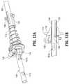
- a knife rod 102is coupled (e.g., via welding) at a distal-most end to the sharpened knife blade 156 and includes an angled proximal end 108 that provides a mechanism for operatively coupling the knife rod 102 to the trigger 126.
- the angled proximal end 108 of the knife rod 102is formed by bending the knife rod 102 ninety degrees at its proximal end during manufacturing. The connection between the knife rod 102 and the trigger 126 is described in detail below with reference to FIGS. 10 , 11 , 12A, and 12B .
- the sharpened distal edge 157 of the knife blade 156may be applied to the distal end of the knife blade 156 using a variety of manufacturing techniques such as, for example, grinding, coining, electrochemical etching, electropolishing, or other suitable manufacturing technique, for forming sharpened edges.
- a tube guide 109is disposed within the outer shaft member 160 and includes a lumen 107 axially disposed therethrough.
- the inner actuation member 180is received within the guide lumen 107, which serves to orient and align the inner actuation member 180 within the outer shaft member 160.
- the knife rod 102is received within a longitudinal guide recess 105 formed in the outer surface of the guide tube 109.
- the guide recess 105serves to guide longitudinal motion of the knife rod 102 within the outer shaft member 160 and to radially space the knife rod 102 from the inner actuation member 180 to prevent the inner actuation member 180 from interfering with reciprocal motion of the knife rod 102.
- the rotation knob 128includes a distal portion 125 extending distally therefrom and a passageway 129 defined therethrough for receiving the outer shaft member 160.
- the passageway 129has a generally circular profile corresponding to the circular profile of the outer shaft member 160.
- the passageway 129includes a longitudinal keying member 124 that is configured to align with and be seated within longitudinal slot 169 ( FIG. 3A ) of the outer shaft member 160.
- the keying member 124projects laterally inward along the length of passageway 129 such that the insertion of the outer shaft member 160 into the passageway 129 of the rotation knob 128 operatively couples the outer shaft member 160 to the rotation knob 128.
- Rotational motion imparted to the rotation knob 128may thus impart rotational motion to each of the components of the elongated shaft 116, and to the end effector 114, which is coupled thereto.
- the rotation knob 128is supported in the housing 112 and, as shown in FIG. 1 , extends radially outward from opposing sides of the housing 112 (only shown extending radially outward from housing half 112b).
- the end effector 114is coupled to the distal end of the inner actuation member 180 by the cam pin 192.
- the cam pin 192represents a longitudinally stationary reference for longitudinal movement of the outer shaft member 160 and the knife rod 102.
- the cam pin 192extends through the flags 132a, 132b of the lower jaw member 132 and the flags 130a and 130b of the upper jaw member 130.
- the end effector 114is shown in the open configuration. Since the inner actuation member 180 is coupled to the cam pin 192, when the outer shaft member 160 (removed from view in FIG. 6 for clarity) is in an unactuated or distal position such that the inner actuation member 180 is in a proximal position relative to the outer shaft member 160, the cam pin 192 is located in a proximal position in cam slots 130c and 132c defined through the flags 130a, 130b, 132a, 132b of the jaw members 130, 132, respectively.
- the outer shaft member 160may be drawn proximally relative to the inner actuation member 180 and the cam pin 192 to move the end effector 114 to the closed configuration (see FIG. 2B ). Since the longitudinal position of the cam pin 192 is fixed, and since the cam slot 130c is obliquely arranged with respect to the longitudinal axis A-A, proximal retraction of the outer shaft member 160 induces distal translation of the cam pin 192 through the cam slots 130c, 132c such that the jaw member 130 pivots toward jaw member 132 about the pivot pin 144.
- the inner actuation member 180may be configured to move relative to the outer shaft member 160 to move the end effector 114 between the open and closed configurations.
- the moveable handle 122may be operably coupled to the inner actuation member 180 and the washer 187 coupled to the proximal portion 188 of the inner actuation member 180 may be removed such that the inner shaft member 180 is free to move longitudinally along the longitudinal axis A-A upon actuation of the moveable handle 122.
- Proximal retraction of the inner actuation member 180may induce proximal translation of the cam pin 192 through the cam slots 130c, 132c such that the jaw member 130 pivots away from jaw member 132 about the pivot pin 144 toward the open configuration.
- the pins 144, 192do not interfere with the reciprocal motion of the knife blade 156.
- a proximal portion of the insulator 142forms a blade guide 152 (also see FIGS. 5 , 8, and 9 ) that serves to align the knife blade 156 such that the knife blade 156 readily enters the knife channel 158 defined in the jaw members 130, 132 (jaw member 130 removed from view in FIG. 7 for clarity).
- the lower jaw member 132is constructed of three major components: the jaw insert 140, the insulator 142, and the sealing plate 148.
- the flags 132a, 132b of the jaw member 132define a proximal portion of the jaw insert 140 and a generally u-shaped profile of the jaw insert 140 extends distally to support the tissue engaging portion of the jaw member 132.
- Upper jaw member 130includes the same three major components as lower jaw member 132, including sealing plate 150, jaw insert 140, and insulator 142, and is constructed in the same manner as lower jaw member 132.
- jaw insert 140 and outer shaft member 160may include complementary alignment features, e.g., a complementary recess (not explicitly shown) defined within jaw insert 140 and a complementary protrusion (not explicitly shown) extending from outer shaft member 160.
- both of the upper and lower jaw members 130, 132, respectivelymay be pivotable relative to one another and outer shaft member 160, thus defining a bilateral configuration.
- the insulator 142 of jaw members 130, 132may be constructed of an electrically insulative plastic such as a polyphthalamide (PPA) (e.g., Amodel®), polycarbonate (PC), acrylonitrile butadiene styrene (ABS), a blend of PC and ABS, nylon, ceramic, etc.
- PPApolyphthalamide
- PCpolycarbonate
- ABSacrylonitrile butadiene styrene
- the insulator 142may be overmolded onto the jaw insert 140 in either a single-shot or a two-shot injection molding process such that each of the sealing plates 148, 150 are coupled to and in spaced relation with their respective jaw inserts 140. Additionally or alternatively, the insulator 142 may be mechanically coupled to the jaw insert 140, e.g., pressed, snapped, glued, etc.
- insulator 142may be molded into the insulator 142 that facilitate the attachment of the sealing plates 148, 150 to the jaw inserts 140.
- tabsmay be provided that permit a snap-fit attachment, or ridges may be formed that permit ultrasonic welding of the sealing plates 148, 150 onto the insulators 142.
- the insulator 142 on the lower jaw member 132forms a tissue stop 142a extending therefrom adjacent to the knife channel 158 and proximal to the sealing plate 148.
- the tissue stop 142aserves to prevent tissue from entering the distal end of the outer shaft member 160 and to prevent splay of the flags 130a, 130b of the upper jaw member 130.
- the tissue stop 142amay be formed by the insulator 142 on the upper jaw member 130 or on both the upper jaw member 130 and the lower jaw member 132.
- the tissue stop 142amay also serve to align the knife blade 156 as the knife blade 156 enters the knife channel 158 defined in the jaw members 130, 132.
- the surface of the tissue stop 142a extending along the path of the knife blade 156may define a chamfered configuration to further facilitate alignment of the knife blade 156 as the knife blade 156 enters the knife channel 158.
- the movable handle 122may be manipulated to impart longitudinal motion to the outer shaft member 160
- the knife trigger 126may be manipulated to impart longitudinal motion to the knife rod 102.
- longitudinal motion of the outer shaft member 160serves to move the end effector 114 between the open configuration of FIG. 2A and the closed configuration of FIG. 2B
- longitudinal motion of the knife rod 102serves to move knife blade 156 through knife channel 158 ( FIG. 2A ).
- the movable handle 122is operatively coupled to the outer shaft member 160 by a clevis 178 defined at an upper end of the movable handle 122.
- the clevis 178is pivotally supported on the housing 112.
- the clevis 178extends upwardly about opposing sides of a drive collar 184 ( FIG. 11 ) supported on the outer shaft member 160 and includes rounded drive surfaces 197a and 197b thereon.
- Drive surface 197aengages a proximal-facing surface of a distal spring washer 184a and drive surface 197b engages a distal facing surface of a proximal rim 184b of the drive collar 184 ( FIG. 11 ).
- the distal spring washer 184aengages a proximal facing surface of a distal spring stop 184c that, in turn, engages the opposing distal locking slots 161 a, 161b ( FIG. 3A ) extending through the proximal portion 166 ( FIG. 3A ) of the outer shaft member 160 to couple the distal spring stop 184c to the outer shaft member 160.
- the drive surfaces 197a, 197bare arranged along the longitudinal axis A-A such that pivotal motion of the movable handle 122 induces corresponding longitudinal motion of the drive collar 184 ( FIG. 11 ) along the longitudinal axis A-A.
- proximal longitudinal motionmay be imparted to the outer shaft member 160 by pushing the proximal rim 184b of the drive collar 184 proximally with the movable handle 122 ( FIG. 10 ) as indicated by arrow D4 ( FIG. 11 ).
- a spring 189is constrained between a proximal facing surface of the drive collar 184 and a proximal spring stop 115.
- the proximal spring stop 115engages the opposing proximal locking slots 171 a, 171b ( FIG. 3A ) extending through the proximal portion 166 ( FIG. 3A ) of the outer shaft member 160 to couple the proximal spring stop 115 to the outer shaft member 160.
- the proximal spring stop 115serves as a proximal stop against which spring 189 compresses.
- Distal longitudinal motionis imparted to the outer shaft member 160 by driving the drive collar 184 distally with the movable handle 122 ( FIG. 10 ).
- Distal longitudinal motion of the drive collar 184induces a corresponding distal motion of the outer shaft member 160 by virtue of the coupling of the drive collar 184 to opposing distal locking slots 181a, 181b extending through the proximal portion 166 of the outer shaft member 160 ( FIG. 3A ).
- a kick-out spring 199is positioned between proximal spring stop 115 and a portion of housing 112 to ensure full return of outer shaft member 160 distally upon release or return of movable handle 122 ( FIG. 10 ).
- the kick-out spring 199may include a pair of plate surfaces interconnected via living hinges, as shown, although any other suitable spring may be provided.
- Proximal longitudinal motion of the outer shaft member 160draws jaw member 132 proximally such that the cam pin 192 advances distally to pivot jaw member 130 toward jaw member 132 to move the end effector 114 to the closed configuration as described above with reference to FIG. 6 .
- the outer shaft member 160essentially bottoms out (i.e., further proximal movement of the outer shaft member 160 is prohibited since the jaw members 130, 132 contact one another).
- Further proximal movement of the movable handle 122FIG. 10
- the trigger 126is pivotally supported in the housing 112 about a pivot boss 103 protruding from the trigger 126.
- the trigger 126is operatively coupled to the knife rod 102 by a knife connection mechanism 104 such that pivotal motion of the trigger 126 induces longitudinal motion of the knife rod 102.
- the knife connection mechanism 104includes upper flanges 126a, 126b of the trigger 126 and a knife collar 110.
- the knife collar 110includes a pair of integrally formed pin bosses 139a, 139b extending from opposing sides thereof. As shown by FIG. 12B , the knife collar 110 includes an interior circular channel 113 that captures the angled proximal end 108 of the knife rod 102 to couple the knife rod 102 to the knife collar 110. Referring momentarily to FIGS. 3C and 3D , in conjunction with FIG. 12B , in some embodiments, the proximal end 108' of the knife rod 102' may alternatively define a hooked configuration to help further inhibit disengagement of the proximal end 108' of the knife rod 102' from within the channel 113 of the knife collar 110.
- the knife slot 168' defined within the outer shaft member 160'further includes an angled portion 168a' disposed at the proximal end thereof to accommodate the hooked proximal end 108' of the knife rod 102'.
- the angled proximal end 108 of the knife rod 102translates longitudinally within knife slot 168 ( FIG. 3A ) of the outer shaft member 160 such that the longitudinal motion of outer shaft member 160 is unimpeded by the angled proximal end 108 of the knife rod 102.
- the angled proximal end 108 of the knife rod 102freely rotates within the interior circular channel 113 of the knife collar 110 such that the outer and inner actuation members 160 and 180 (removed from view in FIG.
- the knife rod 102rotate within the knife collar 110 about the longitudinal axis A-A.
- the knife collar 110serves as a stationary reference for the rotational movement of the outer shaft member 160, the inner actuation member 180, and the knife rod 102.
- the upper flanges 126a, 126b of the trigger 126include respective slots 127a, 127b defined therethrough that are configured to receive the pin bosses 139a, 139b, respectively, of the knife collar 110 such that pivotal motion of the trigger 126 induces longitudinal motion of the knife collar 110 and, thus, the knife rod 102 by virtue of the coupling of knife rod 102 to the knife collar 110.
- a hard stop 156a' formed at the proximal end of knife blade 156'is provided for interference with the pivot pin 144 of end effector 114 ( FIG. 2B ) to limit the travel distance, e.g., extension, of knife blade 156'.
- a sequence of motionsmay be initiated by moving the movable handle 122 to induce motion of the outer shaft member 160 in order to close the jaws 130, 132, and by moving the trigger 126 to induce motion of the knife collar 110 in order to translate the blade 156 through the knife channel 158.
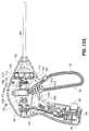
- both the moveable handle 122 and the knife trigger 126are in a distal or un-actuated position as depicted in FIG. 13A .
- This arrangement of the moveable handle 122 and trigger 126sustains the end effector 114 in the open configuration ( FIG.
- Movable handle 122may additionally include a protrusion (not shown) or other feature extending distally therefrom that is configured to contact the trigger 126 upon return of the movable handle 122 distally towards the un-actuated position, thereby returning the trigger 126 towards its un-actuated position if not previously returned via the spring 119 ( FIG. 11 ).
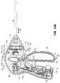
- the movable handle 122may be moved from the distal position of FIG. 13A to the intermediate position depicted in FIG. 13B to move the jaw members 130, 132 to the closed configuration ( FIG. 2B ).
- the drive surface 197b of the movable handle 122engages the proximal rim 184b of the drive collar 184.
- the drive collar 184is driven proximally such that the spring 189 biases the proximal spring stop 115 and, thus, the outer shaft member 160 is driven proximally in the direction of arrow M2 ( FIG. 13B ).
- proximal movement of the outer shaft member 160serves to translate the cam pin 192 distally though the cam slots 130c, 132c ( FIG. 3A ) of the jaw members 130, 132, respectively, and thus pivot jaw member 130 toward jaw member 132 ( FIG. 2B ).
- the jaw members 130, 132engage one another and no further pivotal movement of the jaw members 130, 132 may be achieved, further distal movement of the cam pin 192 and further proximal movement of the outer shaft member 160 are prevented.
- a tooth 122aextending proximally from an upper portion of the moveable handle 122 engages a clicker tab 120a supported within the stationary handle 120 to generate a tactile and/or an audible response.
- the clicker tab 120amay be constructed of a plastic film, sheet metal, or any suitable material configured to generate a "clicking" sound as the clicker tab 120a is engaged and disengaged by the tooth 122a.
- This response generated by the clicker tab 120acorresponds to a complete grasping of tissue between the jaw members 130, 132 and serves to indicate to the surgeon that further pivotal motion of the moveable handle 122 in a proximal direction, i.e., toward the stationary handle 120, will cause the button activation post 138 to engage the depressible button 137.
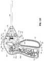
- the button activation post 138depresses the depressible button 137, thereby activating the switch 136 disposed within the stationary handle 120 to initiate the delivery of electrosurgical energy to the end effector 114 to generate a tissue seal.
- the depressible button 137'includes an inner button member 137a' operably coupled to the switch 136', an outer button member 137b' disposed about the inner button member 137a', and a spring 137c' disposed between the inner and outer button members 137a', 137b', respectively.
- the moveable handle 122FIG. 10
- the button activation post 138FIG. 10
- the knife trigger 126When the movable handle 122 is in the actuated or proximal position, the knife trigger 126 may be selectively moved from the distal position of FIG. 13C to the proximal position of FIG 13D to advance the knife blade 156 distally through knife channel 158.
- the knife trigger 126may be pivoted in the direction of arrow M5 ( FIG. 13D ), about pivot boss 103 to advance the flanges 126a, 126b of the knife trigger 126 distally in the direction of arrow M6 such that the pin bosses 139a, 139b translate within respective slots 127a, 127b from the position shown in FIGS. 13A- 13C to the position shown in FIG.
- FIGS. 13A-13Dflange 126b, pin boss 139b, and slot 127b are obstructed from view in FIGS. 13A-13D ). Movement of flanges 126a, 126b draws the knife collar 110 distally, which induces distal longitudinal motion of the knife rod 102 by virtue of the coupling of the knife rod 102 to the knife collar 110, as described above with reference to FIG. 12B .
Landscapes
- Health & Medical Sciences (AREA)
- Surgery (AREA)
- Engineering & Computer Science (AREA)
- Life Sciences & Earth Sciences (AREA)
- Biomedical Technology (AREA)
- Otolaryngology (AREA)
- Nuclear Medicine, Radiotherapy & Molecular Imaging (AREA)
- Plasma & Fusion (AREA)
- Physics & Mathematics (AREA)
- Heart & Thoracic Surgery (AREA)
- Medical Informatics (AREA)
- Molecular Biology (AREA)
- Animal Behavior & Ethology (AREA)
- General Health & Medical Sciences (AREA)
- Public Health (AREA)
- Veterinary Medicine (AREA)
- Surgical Instruments (AREA)
Abstract
Description
- The present disclosure relates generally to the field of surgical instruments. In particular, the disclosure relates to an endoscopic electrosurgical forceps that is economical to manufacture and is capable of sealing and cutting relatively large tissue structures.
- Instruments such as electrosurgical forceps are commonly used in open and endoscopic surgical procedures to coagulate, cauterize and seal tissue. Such forceps typically include a pair of jaw members that can be controlled by a surgeon to grasp targeted tissue, such as, e.g., a blood vessel. The jaw members may be approximated to apply a mechanical clamping force to the tissue, and are associated with at least one electrode to permit the delivery of electrosurgical energy to the tissue. The combination of the mechanical clamping force and the electrosurgical energy has been demonstrated to join adjacent layers of tissue captured between the jaw members. When the adjacent layers of tissue include the walls of a blood vessel, sealing the tissue may result in hemostasis, which may facilitate the transection of the sealed tissue. A detailed discussion of the use of an electrosurgical forceps may be found in
U.S. Patent No. 7,255,697 to Dycus et al. - A bipolar electrosurgical forceps typically includes opposed electrodes disposed on clamping faces of the jaw members. The electrodes are charged to opposite electrical potentials such that an electrosurgical current may be selectively transferred through tissue grasped between the electrodes. To effect a proper seal, particularly in relatively large vessels, two predominant mechanical parameters must be accurately controlled; the pressure applied to the vessel, and the gap distance established between the electrodes.
- Both the pressure and gap distance influence the effectiveness of the resultant tissue seal. If an adequate gap distance is not maintained, there is a possibility that the opposed electrodes will contact one another, which may cause a short circuit and prevent energy from being transferred through the tissue. Also, if too low a force is applied the tissue may have a tendency to move before an adequate seal can be generated. The thickness of a typical effective tissue seal is optimally between about 0.001 and about 0.006 inches. Below this range, the seal may shred or tear and above this range the vessel walls may not be effectively joined. Closure pressures for sealing large tissue structures preferably fall within the range of about 3kg/cm2 to about 16 kg/cm2.
- The present disclosure relates to an electrosurgical apparatus and methods for performing electrosurgical procedures. More particularly, the present disclosure relates to electrosurgically sealing tissue.
- The present disclosure describes an electrosurgical instrument for treating tissue that is economical to manufacture and is capable of sealing and cutting relatively large tissue structures.
- The electrosurgical instrument includes a housing including an elongated shaft having distal and proximal portions. The proximal portion is coupled to the housing. As is traditional, the term "distal" refers herein to an end of the apparatus that is farther from an operator, and the term "proximal" refers herein to the end of the electrosurgical forceps that is closer to the operator.
- The elongated shaft defines a longitudinal axis. A stationary actuation member is axially disposed within the elongated shaft and includes a cam pin mechanically coupled to a distal end thereof. An actuating mechanism is operably coupled to the proximal portion of the elongated shaft and is moveable relative to the housing to selectively cause movement of the elongated shaft along the longitudinal axis relative to the stationary actuation member. An end effector includes a pair of opposing first and second jaw members operably coupled about a common pivot such that at least one of the jaw members is movable relative to the other jaw member from a first position wherein the jaw members are disposed in spaced relation relative to one another to a second position wherein the jaw members cooperate to grasp tissue therebetween. At least one of the first and second jaw members includes a camming slot configured to engage the cam pin to move the at least one movable jaw member between the first position and the second position upon movement of the elongated shaft along the longitudinal axis. Each jaw member includes an electrically conductive tissue sealing surface. Each tissue sealing surface is adapted to connect to a source of electrosurgical energy for conducting electrosurgical energy through tissue grasped therebetween to effect a tissue seal. A knife blade is supported in the elongated shaft and is moveable in a longitudinal direction through a knife channel defined along a length of at least one of the jaw members to cut tissue disposed between the jaw members. A switch is supported by the housing and is configured to be engaged by the actuating mechanism to initiate delivery of electrosurgical energy from the electrosurgical energy source to the end effector to treat tissue.
- Additionally or alternatively, the switch is operably coupled to a depressible button extending from the housing. The button is configured to be selectively engaged by the actuating mechanism to activate the switch.
- Additionally or alternatively, the second jaw member is mechanically coupled to a distal end of the elongated shaft and the first jaw member is configured to move relative to the second jaw member.
- Additionally or alternatively, the stationary actuation member includes a longitudinal recess formed along a length thereof. The longitudinal recess is configured to permit movement of the pivot pin in a longitudinal direction upon movement of the elongated shaft.
- Additionally or alternatively, the actuation mechanism is configured to engage a mechanical interface disposed within the housing. The mechanical interface is configured to generate a response to engagement with the actuation mechanism upon movement thereof relative to the housing. The mechanical interface may be constructed of a plastic film or the mechanical interface may be constructed of sheet metal. The response may be tactile and/or audible and may correspond to the second position of at least one jaw member. Additionally or alternatively, the response may indicate a position of the actuation mechanism relative to the switch.
- Additionally or alternatively, the actuation mechanism includes a handle moveable relative to the housing between a distal position to move at least one jaw member to the first position and a proximal position to move the at least one jaw member to the second position. The handle may engage the switch upon movement of the handle to the proximal position.
- Additionally or alternatively, movement of the knife blade in a longitudinal direction is prevented when the handle is in the distal position.
- Additionally or alternatively, at least one of the jaw members includes an insulator coupled thereto. The insulator may be configured to electrically insulate the electrically conductive tissue sealing surface from the jaw member. The insulator may form at least one knife blade guide configured to guide the knife into the knife channel.
- Additionally or alternatively, the insulator is configured to control splay of at least one of the jaw members.
- According to another aspect of the present disclosure, an electrosurgical instrument is provided. The electrosurgical instrument includes a housing and an elongated shaft coupled to the housing and defining a longitudinal axis. An actuating mechanism is operably coupled to the elongated shaft and moveable relative to the housing to selectively cause movement of the elongated shaft along the longitudinal axis. An end effector is supported by the elongated shaft and is adapted for treating tissue. The end effector includes first and second jaw members pivotally coupled to one another to move between open and closed configurations. Each of the jaw members includes a camming surface. A switch is supported by the housing and is configured to be engaged by the actuating mechanism to initiate treatment of tissue. A knife rod extends at least partially through the elongated shaft and is selectively movable in a longitudinal direction. A blade operably coupled to the knife rod is extendable through a knife channel defined along a length of at least one of the jaw members. An inner actuation member extends at least partially through the elongated shaft and the elongated shaft is selectively movable in a longitudinal direction with respect to the knife and with respect to the inner actuation member. The inner actuation member carries a cam pin positioned to engage the camming surface of each of the jaw members to induce the jaw members to move between the open and closed configurations.
- According to another aspect of the present disclosure, an electrosurgical system for performing electrosurgery is provided. The electrosurgical system includes an electrosurgical generator configured to provide electrosurgical energy and an electrosurgical instrument. The electrosurgical instrument includes a housing including an elongated shaft having distal and proximal portions. The proximal portion is coupled to the housing. The elongated shaft defines a longitudinal axis. A stationary actuation member is axially disposed within the elongated shaft and includes a cam pin mechanically coupled to a distal end thereof. An actuating mechanism is operably coupled to the proximal portion of the elongated shaft and is moveable relative to the housing to selectively cause movement of the elongated shaft along the longitudinal axis relative to the stationary actuation member. An end effector includes a pair of opposing first and second jaw members operably coupled about a common pivot such that at least one of the jaw members is movable relative to the other jaw member from a first position wherein the jaw members are disposed in spaced relation relative to one another to a second position wherein the jaw members cooperate to grasp tissue therebetween. At least one of the first and second jaw members includes a camming slot configured to engage the cam pin to move the at least one movable jaw member between the first position and the second position upon movement of the elongated shaft along the longitudinal axis. Each jaw member includes an electrically conductive tissue sealing surface. Each tissue sealing surface is configured to connect to the electrosurgical generator for conducting electrosurgical energy through tissue grasped therebetween to effect a tissue seal. A knife blade is supported in the elongated shaft and is moveable in a longitudinal direction through a knife channel defined along a length of at least one of the jaw members to cut tissue disposed between the jaw members. A switch is supported by the housing and is configured to be engaged by the actuating mechanism to initiate delivery of electrosurgical energy from the electrosurgical generator to the end effector to treat tissue.
- In another aspect of the present disclosure, there is provided a surgical instrument, comprising: a housing; an elongated shaft including distal and proximal portions, the proximal portion coupled to the housing, the elongated shaft defining a longitudinal axis; an actuating mechanism operably coupled to the proximal portion of the elongated shaft and moveable relative to the housing to selectively cause movement of the elongated shaft along the longitudinal axis; an end effector supported by the distal portion of the elongated shaft, the end effector adapted for treating tissue and including first and second jaw members pivotally coupled to one another to move between open and closed configurations, wherein each of the jaw members includes a camming surface thereon; the inner actuation member extending at least partially through the elongated shaft, the elongated shaft selectively movable in a longitudinal direction with respect to the inner actuation member, the inner actuation member carrying a cam pin positioned to engage the camming surface of each of the jaw members to induce the jaw members to move between the open and closed configurations.
- In embodiments of the various aspects, the jaw members are pivotable about a pivot pin to move the end effector between the open and closed configurations.
- In an embodiment, the pivot pin is longitudinally reciprocable via longitudinal reciprocation of the elongated shaft independent of the inner actuation member.
- In an embodiment, a distal portion of the inner actuation member includes a longitudinal recess defined therein that provides clearance for the pivot pin and thus, permits longitudinal reciprocation of the pivot pin independent of the inner actuation member.
- In embodiments of the various aspects, the inner actuation member is longitudinally fixed relative to the housing.
- In embodiments of the various aspects, the elongated shaft is longitudinally moveable relative to the housing upon actuation.
- In an embodiment, the pivot pin extends through a proximal portion of each of the jaw members to pivotally support the jaw members wherein a proximal portion of each of the jaw members includes two laterally spaced parallel flanges or "flags" respectively, extending proximally from a distal portion of the jaw members. A lateral cam slot forming part of the camming surface and a lateral pivot bore for receiving the pivot pin extend through each of the flags of each of the jaws.
- In an embodiment of the present aspect, a switch is supported by the housing and configured to be engaged by the actuating mechanism to initiate treatment of tissue.
- In another embodiment of the present aspect, a knife rod extends at least partially through the elongated shaft and is selectively movable in a longitudinal direction. A blade is operably coupled to the knife rod and is extendable through a knife channel defined along a length of at least one of the jaw members.
- In an embodiment, the proximal portion of one of the jaw members includes a blade guide, e.g. the guide including a channel, that serves to align the knife blade such that the knife blade is guided to enter the knife channel defined in the distal portion of the at least one of the jaw members.
- In an embodiment, at least part of the blade guide is included in an insulator of the proximal portion os that the knife blade is guided to enter a knife slot in a seal plate of the jaw member.
- In embodiments of the various aspect, one of the members is fixedly engaged to the elongated shaft while the other of the jaw members is pivotable relative to the one of the jaw members between the open and closed configurations.
- In embodiments of the various aspects, a tube guide is disposed with in the elongated shaft member and includes a guide lumen axially disposed therethrough, wherein the inner actuation member is received within the guide lumen, which serves to orient and align the inner actuation member within the elongated shaft. In embodiments including the knife rod, the knife rod is received within a longitudinal guide recess formed in the outer surface of the guide tube, wherein the guide recess serves to guide longitudinal motion of the knife rod within the elongated shaft member.
- In embodiments of the various aspects including the knife rod, the knife rod is radially spaced from the inner actuation member to prevent the inner actuation member from interfering with reciprocal motion of the knife rod. The inner actuation member may be centrally disposed within the elongated shaft in the radial direction.
- In embodiments of the various aspects, a knife trigger is pivotally supported in the housing and is operatively coupled to the knife rod by a knife connection mechanism such that pivotal motion of the trigger induces longitudinal motion of the knife rod, wherein the knife connection mechanism includes a knife collar that captures an angled proximal end of the knife rod to couple the knife rod to the knife collar. In an embodiment, the knife collar includes an interior circular channel that captures the angled proximal end of the knife rod to couple the knife rod to the knife collar and to allow relative rotation of the knife collar and the knife rod.
- In embodiments, upon longitudinal motion of the elongated shaft, the angled proximal end of the knife rod translates longitudinally, within a knife slot of the elongated shaft.
- In embodiments of the various aspects, the actuating mechanism includes a movable handle movable/pivotable from a distal position corresponding to the open configuration of the jaw members to an intermediate position corresponding to the closed configuration of the jaw members.
- In an embodiment, a portion of the moveable handle engages a clicker mechanism supported in the housing to generate a clicking sound as the clicker mechanism is engaged corresponding to a complete grasping of tissue between the jaw members and serving to indicate such to a surgeon.
- In an embodiment of aspects including the switch, the click serves to indicate to the surgeon that further movement of the moveable handle will cause the moveable handle to engage and activate the switch.
- In embodiments of the various aspects, the moveable handle is movable from an intermediate position corresponding to the closed configuration of the jaw members to the actuated position in which a part of the handle depresses a depressible button, thereby activating the switch to initiate the delivery of electrosurgical energy to the end effector to generate a tissue seal.
- In an embodiment, the instrument is configured so that pressure applied between the jaw members is increased as the moveable handle moves from the intermediate position to the actuated position.
- The accompanying drawings, which are incorporated in and constitute a part of this specification, illustrate embodiments of the present disclosure and, together with the detailed description of the embodiments given below, serve to explain the principles of the disclosure.
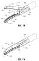
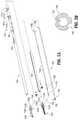
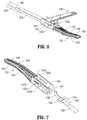
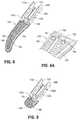
FIG. 1 is a perspective view of an electrosurgical forceps according to an embodiment of the present disclosure including a housing, an elongated shaft, and an end effector;FIG. 2A is an enlarged, perspective view of the end effector ofFIG. 1 depicted with a pair of jaw members in an open configuration;FIG. 2B is an enlarged, perspective view of the end effector ofFIG. 1 depicted with the pair of jaw members in a closed configuration;FIG. 3A is a perspective view of the end effector and elongated shaft ofFIG. 1 with parts separated;FIG. 3B is cross-sectional view taken alongline 3B-3B ofFIG. 3A showing a distal portion of the electrosurgical forceps ofFIG. 1 depicting a tube guide;FIG. 3C is a perspective view of another knife blade and knife bar configuration for use with the end effector and elongated shaft ofFIG. 1 ;FIG. 3D is an enlarged, perspective view of the area of detail indicated inFIG. 3C ;FIG. 3E is a perspective view of a portion of another elongated shaft, similar to the elongated shaft ofFIG. 1 , configured for use with the end effector ofFIG. 1 ;FIG. 4 is a proximally-facing, perspective view of a rotation knob depicting a passageway for receiving the elongated shaft ofFIG. 1 ;FIG. 5 is a cross-sectional, perspective view of the end effector ofFIG. 1 ;FIG. 6 is a partial, proximal-facing perspective view of a distal portion of a jaw actuation mechanism of the end effector ofFIG. 1 ;FIG. 7 is a partial, distal-facing perspective view of distal portion of a knife actuation mechanism of the end effector ofFIG. 1 ;FIG. 8 is a perspective view of a lower jaw member of the end effector ofFIG. 1 ;FIG. 8A is an enlarged, perspective view of a portion of another lower jaw member, similar to the lower jaw member ofFIG. 8 , configured for use with the end effector ofFIG. 1 ;FIG. 9 is a cross-sectional, perspective view of the lower jaw member ofFIG. 8 ;FIG. 10 is a perspective view of a proximal portion of the instrument ofFIG. 1 with a portion of the housing removed revealing internal components;FIG. 10A is a cross-sectional view of another switch and activation button configured for use with the instrument ofFIG. 1 ;FIG. 11 is a partial, side view of a proximal portion of the instrument ofFIG. 1 ;FIG. 12A is a perspective view of a proximal portion of the knife actuation mechanism of the end effector ofFIG. 1 ;FIG. 12B is a cross-sectional, side view of a knife collar of the knife actuation mechanism of the end effector ofFIG. 1 ;FIG. 13A is a side view of the proximal portion of the instrument ofFIG. 10 depicting a movable handle in a separated position with respect to a stationary handle, which corresponds to the open configuration of the end effector depicted inFIG. 2A , and a knife trigger in a separated configuration with respect to the stationary handle, which corresponds to an un-actuated or proximal configuration of a knife with respect to the jaw members;FIG. 13B is a side view of the proximal portion of the instrument ofFIG. 10 depicting the movable handle in an intermediate position with respect to the stationary handle, which corresponds to a first closed configuration of the end effector wherein the jaw members encounter one another;FIG. 13C is a side view of the proximal portion of the instrument ofFIG. 10 depicting the movable handle in an approximated configuration with respect to the stationary handle, which corresponds to a second closed configuration of the end effector wherein the jaw members apply an appropriate pressure to generate a tissue seal; andFIG. 13D is a side view of the proximal portion of the instrument ofFIG. 10 depicting the knife trigger in an actuated configuration, which corresponds to an actuated or distal position of the knife with respect to the jaw members.- Referring initially to
FIG. 1 , anelectrosurgical forceps 100 generally includes ahousing 112 that supports various actuators thereon for remotely controlling anend effector 114 through anelongated shaft 116. Although this configuration is typically associated with instruments for use in laparoscopic or endoscopic surgical procedures, various aspects of the present disclosure may be practiced with traditional open instruments and in connection with endoluminal procedures as well. Thehousing 112 is constructed of aleft housing half 112a and aright housing half 112b. The left and right designation of thehousing halves forceps 100. Thehousing halves - To mechanically control the
end effector 114, thehousing 112 supports astationary handle 120, amovable handle 122, atrigger 126 and arotation knob 128. Themovable handle 122 is operable to move theend effector 114 between an open configuration (FIG. 2A ) wherein a pair ofopposed jaw members FIG. 2B ) wherein thejaw members movable handle 122 with thestationary handle 120 serves to move theend effector 114 to the closed configuration and separation of themovable handle 122 from thestationary handle 120 serves to move theend effector 114 to the open configuration. Thetrigger 126 is operable to extend and retract a knife blade 156 (seeFIGS. 2A and 2B ) through theend effector 114 when theend effector 114 is in the closed configuration. Therotation knob 128 serves to rotate theelongated shaft 116 and theend effector 114 about a longitudinal axis A-A extending through theforceps 114. - To electrically control the
end effector 114, thestationary handle 120 supports adepressible button 137 thereon, which is operable by the user to initiate and terminate the delivery of electrosurgical energy to theend effector 114. Thedepressible button 137 is mechanically coupled to a switch 136 (FIGS. 13A-13D ) disposed within thestationary handle 120 and is engageable by abutton activation post 138 extending from a proximal side of themoveable handle 122 upon proximal movement of themoveable handle 122 to an actuated or proximal position (FIG. 13C ). Theswitch 136 is in electrical communication with anelectrosurgical generator 141 via suitable electrical wiring (not explicitly referenced) extending from thehousing 112 through acable 143 extending between thehousing 112 and theelectrosurgical generator 141. Thegenerator 141 may include devices such as the LigaSure® Vessel Sealing Generator and the ForceTriad® Generator sold by Covidien. Thecable 143 may include a connector (not shown) thereon such that theforceps 100 may be selectively coupled electrically to thegenerator 141. - Referring now to
FIGS. 2A - 3A , theend effector 114 may be moved from the open configuration (FIG. 2A ) wherein tissue (not shown) is received between thejaw members FIG. 2B ), wherein the tissue is clamped and treated. Thejaw members pivot pin 144 to move theend effector 114 to the closed configuration ofFIG. 2B wherein the sealingplates plates FIG. 2A ) disposed on or adjacent the sealingplates stop members 154 contact opposing surfaces on the opposingjaw member plates stop members 154 are constructed of a heat-resistant ceramic deposited onto thejaw members stop members 154 are constructed of an electrically non-conductive plastic molded onto thejaw members stop members 154 may define any suitable number, arrangement, and/or configuration, depending on a particular purpose. - Referring momentarily to
FIG. 8A , another embodiment of a lower jaw member 132' is shown. Lower jaw member 132' is similar to lower jaw member 132 (FIGS. 2A - 3A ) except as detailed below. Lower jaw member 132' includes a sealing plate 148' having a plurality of stop members 154' disposed thereon in any suitable configuration. A wetting ring 155' defined within the sealing plate 148' is disposed about each of the stop members 154'. Wetting rings 155' may be formed via etching or other suitable process and are formed on sealing plate 148' prior to depositing (or otherwise forming) the stop members 154'. Upon depositing the ceramic onto sealing plate 148' to form the stop members 154' (or prior to otherwise forming the stop members 154'), wetting rings 155' facilitate the formation of each of the stop members 154' in a particular shape, e.g., circular, thus providing greater shape uniformity among the plurality of stop members 154'. - Referring again to
FIGS. 2A - 3A , the upper andlower jaw members cable 143, and thus to the generator 141 (e.g., via respective suitable electrical wiring extending through the elongated shaft 116) to provide an electrical pathway to a pair of electrically conductive, tissue-engagingsealing plates upper jaw members plate 148 of thelower jaw member 132 opposes the sealingplate 150 of theupper jaw member 130. In some embodiments, the sealingplates generator 141. Thus, bipolar energy may be provided through the sealingplates plates plates generator 141. Eachjaw member ajaw insert 140 and aninsulator 142 that serves to electrically insulate the sealingplates jaw insert 140 of thejaw members - Electrosurgical energy may be delivered to the tissue through the electrically
conductive seal plates knife blade 156 having a sharpeneddistal edge 157 may be advanced through aknife channel 158 defined in one or bothjaw members knife blade 156 is depicted inFIG. 2A as extending from theelongated shaft 116 when theend effector 114 is in an open configuration, in some embodiments, extension of theknife blade 156 into theknife channel 158 when theend effector 114 is in the open configuration is prevented, as discussed below with reference toFIGS. 13A-13D . - Referring to
FIG. 3A , theelongated shaft 116 includes various longitudinal components that operatively couple theend effector 114 to the various actuators supported by the housing 112 (FIG. 1 ). Anouter shaft member 160 defines an exterior surface of theelongated shaft 116 and houses other components therein as described below. Theouter shaft member 160 is configured for longitudinal motion with respect to aninner actuation member 180 axially received within theouter shaft member 160. Theinner actuation member 180 may be a rod, a shaft, a tube, folded metal, stamped metal, or other suitable structure. Aproximal portion 166 of theouter shaft member 160 is configured for receipt within the housing 112 (FIG. 1 ), and includes features for operatively coupling theouter shaft member 160 to various elements of thehousing 112. More specifically, theproximal portion 166 of theouter shaft member 160 includes, in order from distal to proximal, alongitudinal slot 169 to couple theouter shaft member 160 to therotation knob 128, alongitudinal knife slot 168 defined therethrough, a pair of opposingdistal locking slots proximal locking slots outer shaft member 160 and therotation knob 128 is described below with reference toFIG. 4 . - A
distal portion 186 of theinner actuation member 180 includes alongitudinal recess 190 defined therein that provides clearance for thepivot pin 144 and thus, permits longitudinal reciprocation of the pivot pin 144 (via longitudinal reciprocation of the outer shaft member 160) independent of theinner actuation member 180. Distally of thelongitudinal recess 190, acam pin 192 is mechanically coupled (e.g., via welding, friction-fit, laser welding, etc) to thedistal portion 186 of theinner actuation member 180. Aproximal portion 188 of theinner actuation member 180 includes awasher 187 coupled thereto (FIG. 10 ). Thewasher 187 is captured within thehousing 112 and serves to prohibit longitudinal motion of theinner actuation member 180 parallel to the longitudinal axis A-A. - The
pivot pin 144 extends through a proximal portion of each of thejaw members jaw members inner actuation member 180. A proximal portion of each of thejaw members jaw members 130 and 132 (FIGS. 3A, 5, and 7-9 ). Alateral cam slot 130c and alateral pivot bore 130d extend through each of theflags FIG. 3A ). Similarly, alateral cam slot 132c and alateral pivot bore 132d extend through each of theflags FIGS. 8 and 9 ). The pivot bores 130d, 132d receive thepivot pin 144 in a slip-fit relation that permits thejaw members pivot pin 144 to move theend effector 114 between the open and closed configurations (FIGS. 2A and 2B , respectively). - A
knife rod 102 is coupled (e.g., via welding) at a distal-most end to the sharpenedknife blade 156 and includes an angledproximal end 108 that provides a mechanism for operatively coupling theknife rod 102 to thetrigger 126. In some embodiments, the angledproximal end 108 of theknife rod 102 is formed by bending theknife rod 102 ninety degrees at its proximal end during manufacturing. The connection between theknife rod 102 and thetrigger 126 is described in detail below with reference toFIGS. 10 ,11 ,12A, and 12B . The sharpeneddistal edge 157 of theknife blade 156 may be applied to the distal end of theknife blade 156 using a variety of manufacturing techniques such as, for example, grinding, coining, electrochemical etching, electropolishing, or other suitable manufacturing technique, for forming sharpened edges. - Referring to
FIGS. 3A and 3B , atube guide 109 is disposed within theouter shaft member 160 and includes alumen 107 axially disposed therethrough. Theinner actuation member 180 is received within theguide lumen 107, which serves to orient and align theinner actuation member 180 within theouter shaft member 160. Theknife rod 102 is received within alongitudinal guide recess 105 formed in the outer surface of theguide tube 109. Theguide recess 105 serves to guide longitudinal motion of theknife rod 102 within theouter shaft member 160 and to radially space theknife rod 102 from theinner actuation member 180 to prevent theinner actuation member 180 from interfering with reciprocal motion of theknife rod 102. - Referring now to
FIG. 4 , therotation knob 128 includes adistal portion 125 extending distally therefrom and apassageway 129 defined therethrough for receiving theouter shaft member 160. Thepassageway 129 has a generally circular profile corresponding to the circular profile of theouter shaft member 160. Thepassageway 129 includes alongitudinal keying member 124 that is configured to align with and be seated within longitudinal slot 169 (FIG. 3A ) of theouter shaft member 160. The keyingmember 124 projects laterally inward along the length ofpassageway 129 such that the insertion of theouter shaft member 160 into thepassageway 129 of therotation knob 128 operatively couples theouter shaft member 160 to therotation knob 128. Rotational motion imparted to therotation knob 128 may thus impart rotational motion to each of the components of theelongated shaft 116, and to theend effector 114, which is coupled thereto. As shown inFIGS. 10 ,11 , and13A-13D , therotation knob 128 is supported in thehousing 112 and, as shown inFIG. 1 , extends radially outward from opposing sides of the housing 112 (only shown extending radially outward fromhousing half 112b). - Referring now to
FIG. 5 , theend effector 114 is coupled to the distal end of theinner actuation member 180 by thecam pin 192. Thecam pin 192 represents a longitudinally stationary reference for longitudinal movement of theouter shaft member 160 and theknife rod 102. Thecam pin 192 extends through theflags lower jaw member 132 and theflags upper jaw member 130. - Referring now to
FIG. 6 , theend effector 114 is shown in the open configuration. Since theinner actuation member 180 is coupled to thecam pin 192, when the outer shaft member 160 (removed from view inFIG. 6 for clarity) is in an unactuated or distal position such that theinner actuation member 180 is in a proximal position relative to theouter shaft member 160, thecam pin 192 is located in a proximal position incam slots flags jaw members - The
outer shaft member 160 may be drawn proximally relative to theinner actuation member 180 and thecam pin 192 to move theend effector 114 to the closed configuration (seeFIG. 2B ). Since the longitudinal position of thecam pin 192 is fixed, and since thecam slot 130c is obliquely arranged with respect to the longitudinal axis A-A, proximal retraction of theouter shaft member 160 induces distal translation of thecam pin 192 through thecam slots jaw member 130 pivots towardjaw member 132 about thepivot pin 144. Conversely, when theend effector 114 is in the closed configuration, longitudinal translation of theouter shaft member 160 in a distal direction induces proximal translation of thecam pin 192 through thecam slots jaw member 130 pivots away fromjaw member 132 toward the open configuration. - In some embodiments, the
inner actuation member 180 may be configured to move relative to theouter shaft member 160 to move theend effector 114 between the open and closed configurations. In this scenario, themoveable handle 122 may be operably coupled to theinner actuation member 180 and thewasher 187 coupled to theproximal portion 188 of theinner actuation member 180 may be removed such that theinner shaft member 180 is free to move longitudinally along the longitudinal axis A-A upon actuation of themoveable handle 122. Proximal retraction of theinner actuation member 180 may induce proximal translation of thecam pin 192 through thecam slots jaw member 130 pivots away fromjaw member 132 about thepivot pin 144 toward the open configuration. Conversely, when theend effector 114 is in the open configuration, longitudinal translation of theinner actuation member 180 in a distal direction induces distal translation of thecam pin 192 through thecam slots jaw member 130 pivots towardjaw member 132 toward the closed configuration. - Referring now to
FIG. 7 , thepins knife blade 156. A proximal portion of theinsulator 142 forms a blade guide 152 (also seeFIGS. 5 ,8, and 9 ) that serves to align theknife blade 156 such that theknife blade 156 readily enters theknife channel 158 defined in thejaw members 130, 132 (jaw member 130 removed from view inFIG. 7 for clarity). - Referring now to
FIGS. 8 and 9 , thelower jaw member 132 is constructed of three major components: thejaw insert 140, theinsulator 142, and the sealingplate 148. Theflags jaw member 132 define a proximal portion of thejaw insert 140 and a generally u-shaped profile of thejaw insert 140 extends distally to support the tissue engaging portion of thejaw member 132.Upper jaw member 130 includes the same three major components aslower jaw member 132, including sealingplate 150,jaw insert 140, andinsulator 142, and is constructed in the same manner aslower jaw member 132. However,lower jaw member 132 is fixedly engaged, e.g., welded, toouter shaft member 160, whileupper jaw member 130 is pivotable relative tolower jaw member 132 andouter shaft member 160 between the open and closed configurations. In order to facilitate alignment oflower jaw member 132 and, more particularly,jaw insert 140 oflower jaw member 132, withouter shaft member 160 during welding (or other suitable fixed engagement),jaw insert 140 andouter shaft member 160 may include complementary alignment features, e.g., a complementary recess (not explicitly shown) defined withinjaw insert 140 and a complementary protrusion (not explicitly shown) extending fromouter shaft member 160. As an alternative to the unilateral configuration detailed above, both of the upper andlower jaw members outer shaft member 160, thus defining a bilateral configuration. - The
insulator 142 ofjaw members insulator 142 may be overmolded onto thejaw insert 140 in either a single-shot or a two-shot injection molding process such that each of the sealingplates insulator 142 may be mechanically coupled to thejaw insert 140, e.g., pressed, snapped, glued, etc. Various features may be molded into theinsulator 142 that facilitate the attachment of the sealingplates plates insulators 142. In some embodiments, theinsulator 142 on thelower jaw member 132 forms atissue stop 142a extending therefrom adjacent to theknife channel 158 and proximal to the sealingplate 148. Thetissue stop 142a serves to prevent tissue from entering the distal end of theouter shaft member 160 and to prevent splay of theflags upper jaw member 130. In some embodiments, thetissue stop 142a may be formed by theinsulator 142 on theupper jaw member 130 or on both theupper jaw member 130 and thelower jaw member 132. Thetissue stop 142a may also serve to align theknife blade 156 as theknife blade 156 enters theknife channel 158 defined in thejaw members tissue stop 142a extending along the path of theknife blade 156 may define a chamfered configuration to further facilitate alignment of theknife blade 156 as theknife blade 156 enters theknife channel 158. - Referring now to
FIG. 10 , the connection of themovable handle 122 and theknife trigger 126 to the longitudinally movable components of theelongated shaft 116 is described. Themovable handle 122 may be manipulated to impart longitudinal motion to theouter shaft member 160, and theknife trigger 126 may be manipulated to impart longitudinal motion to theknife rod 102. As discussed above, longitudinal motion of theouter shaft member 160 serves to move theend effector 114 between the open configuration ofFIG. 2A and the closed configuration ofFIG. 2B , and longitudinal motion of theknife rod 102 serves to moveknife blade 156 through knife channel 158 (FIG. 2A ). - The
movable handle 122 is operatively coupled to theouter shaft member 160 by aclevis 178 defined at an upper end of themovable handle 122. Theclevis 178 is pivotally supported on thehousing 112. Theclevis 178 extends upwardly about opposing sides of a drive collar 184 (FIG. 11 ) supported on theouter shaft member 160 and includesrounded drive surfaces Drive surface 197a engages a proximal-facing surface of adistal spring washer 184a and drivesurface 197b engages a distal facing surface of aproximal rim 184b of the drive collar 184 (FIG. 11 ). Thedistal spring washer 184a engages a proximal facing surface of adistal spring stop 184c that, in turn, engages the opposingdistal locking slots FIG. 3A ) extending through the proximal portion 166 (FIG. 3A ) of theouter shaft member 160 to couple thedistal spring stop 184c to theouter shaft member 160. The drive surfaces 197a, 197b are arranged along the longitudinal axis A-A such that pivotal motion of themovable handle 122 induces corresponding longitudinal motion of the drive collar 184 (FIG. 11 ) along the longitudinal axis A-A. - Referring now to
FIG. 11 , proximal longitudinal motion may be imparted to theouter shaft member 160 by pushing theproximal rim 184b of thedrive collar 184 proximally with the movable handle 122 (FIG. 10 ) as indicated by arrow D4 (FIG. 11 ). Aspring 189 is constrained between a proximal facing surface of thedrive collar 184 and aproximal spring stop 115. Theproximal spring stop 115 engages the opposingproximal locking slots FIG. 3A ) extending through the proximal portion 166 (FIG. 3A ) of theouter shaft member 160 to couple theproximal spring stop 115 to theouter shaft member 160. Thus, theproximal spring stop 115 serves as a proximal stop against which spring 189 compresses. - Distal longitudinal motion is imparted to the
outer shaft member 160 by driving thedrive collar 184 distally with the movable handle 122 (FIG. 10 ). Distal longitudinal motion of thedrive collar 184 induces a corresponding distal motion of theouter shaft member 160 by virtue of the coupling of thedrive collar 184 to opposing distal locking slots 181a, 181b extending through theproximal portion 166 of the outer shaft member 160 (FIG. 3A ). In some embodiments, a kick-outspring 199 is positioned betweenproximal spring stop 115 and a portion ofhousing 112 to ensure full return ofouter shaft member 160 distally upon release or return of movable handle 122 (FIG. 10 ). The kick-outspring 199 may include a pair of plate surfaces interconnected via living hinges, as shown, although any other suitable spring may be provided. - Proximal longitudinal motion of the
outer shaft member 160 drawsjaw member 132 proximally such that thecam pin 192 advances distally to pivotjaw member 130 towardjaw member 132 to move theend effector 114 to the closed configuration as described above with reference toFIG. 6 . Once thejaw members outer shaft member 160 essentially bottoms out (i.e., further proximal movement of theouter shaft member 160 is prohibited since thejaw members FIG. 10 ), however, will continue to move thedrive collar 184 proximally. This continued proximal movement of thedrive collar 184 further compresses thespring 189 to impart additional force to theouter shaft member 160, which results in additional closure force applied to tissue grasped between thejaw members 130, 132 (seeFIG. 2B ). - Referring again to
FIG. 10 , thetrigger 126 is pivotally supported in thehousing 112 about apivot boss 103 protruding from thetrigger 126. Thetrigger 126 is operatively coupled to theknife rod 102 by aknife connection mechanism 104 such that pivotal motion of thetrigger 126 induces longitudinal motion of theknife rod 102. Theknife connection mechanism 104 includesupper flanges trigger 126 and aknife collar 110. - Referring now to
FIGS. 11 ,12A, and 12B , theknife collar 110 includes a pair of integrally formed pin bosses 139a, 139b extending from opposing sides thereof. As shown byFIG. 12B , theknife collar 110 includes an interiorcircular channel 113 that captures the angledproximal end 108 of theknife rod 102 to couple theknife rod 102 to theknife collar 110. Referring momentarily toFIGS. 3C and 3D , in conjunction withFIG. 12B , in some embodiments, the proximal end 108' of the knife rod 102' may alternatively define a hooked configuration to help further inhibit disengagement of the proximal end 108' of the knife rod 102' from within thechannel 113 of theknife collar 110. In such embodiments, as shown inFIG. 3E , the knife slot 168' defined within the outer shaft member 160' further includes anangled portion 168a' disposed at the proximal end thereof to accommodate the hooked proximal end 108' of the knife rod 102'. - Referring again to
FIGS. 11 ,12A, and 12B , upon longitudinal motion of theouter shaft member 160, the angledproximal end 108 of theknife rod 102 translates longitudinally within knife slot 168 (FIG. 3A ) of theouter shaft member 160 such that the longitudinal motion ofouter shaft member 160 is unimpeded by the angledproximal end 108 of theknife rod 102. Upon rotation of theelongated shaft 116 andend effector 114 about the longitudinal axis A-A via the rotation knob 128 (FIG. 1 ), the angledproximal end 108 of theknife rod 102 freely rotates within the interiorcircular channel 113 of theknife collar 110 such that the outer andinner actuation members 160 and 180 (removed from view inFIG. 12B for clarity), and theknife rod 102 rotate within theknife collar 110 about the longitudinal axis A-A. In this way, theknife collar 110 serves as a stationary reference for the rotational movement of theouter shaft member 160, theinner actuation member 180, and theknife rod 102. - Referring again to
FIG. 10 , theupper flanges trigger 126 includerespective slots 127a, 127b defined therethrough that are configured to receive the pin bosses 139a, 139b, respectively, of theknife collar 110 such that pivotal motion of thetrigger 126 induces longitudinal motion of theknife collar 110 and, thus, theknife rod 102 by virtue of the coupling ofknife rod 102 to theknife collar 110. - Referring now to
FIGS. 11 and12A , when thetrigger 126 is moved to induce motion of theknife collar 110 in order to translate theblade 156 through theknife channel 158, theknife collar 110 translates along theouter shaft member 160 in the direction of arrow A5 to abut aspring 119 such thatspring 119 compresses against thedistal portion 125 of the rotation knob 128 (FIG. 12A ). Thespring 119 biases theknife collar 110 proximally along theouter shaft member 160. With reference toFIG. 3C , in some embodiments, ahard stop 156a' formed at the proximal end of knife blade 156' is provided for interference with thepivot pin 144 of end effector 114 (FIG. 2B ) to limit the travel distance, e.g., extension, of knife blade 156'. - Referring now to
FIGS. 13A ,13B ,13C and13D , a sequence of motions may be initiated by moving themovable handle 122 to induce motion of theouter shaft member 160 in order to close thejaws trigger 126 to induce motion of theknife collar 110 in order to translate theblade 156 through theknife channel 158. Initially, both themoveable handle 122 and theknife trigger 126 are in a distal or un-actuated position as depicted inFIG. 13A . This arrangement of themoveable handle 122 and trigger 126 sustains theend effector 114 in the open configuration (FIG. 2A ) wherein thejaw members knife blade 156 is in a retracted or proximal position with respect to thejaw members moveable handle 122 and theknife trigger 126 are in the distal, un-actuated position, pivotal motion of theknife trigger 126 in a proximal direction, i.e., toward thestationary handle 120, is passively prohibited by interference between thetrigger 126 andmoveable handle 122. This interference prohibits advancement of theknife blade 156 through theknife channel 158 when theend effector 114 is in the open configuration.Movable handle 122 may additionally include a protrusion (not shown) or other feature extending distally therefrom that is configured to contact thetrigger 126 upon return of themovable handle 122 distally towards the un-actuated position, thereby returning thetrigger 126 towards its un-actuated position if not previously returned via the spring 119 (FIG. 11 ). - The
movable handle 122 may be moved from the distal position ofFIG. 13A to the intermediate position depicted inFIG. 13B to move thejaw members FIG. 2B ). As themovable handle 122 pivots in the direction of arrow M1 (FIG. 13B ), thedrive surface 197b of themovable handle 122 engages theproximal rim 184b of thedrive collar 184. Thedrive collar 184 is driven proximally such that thespring 189 biases theproximal spring stop 115 and, thus, theouter shaft member 160 is driven proximally in the direction of arrow M2 (FIG. 13B ). As discussed above with reference toFIG. 6 , proximal movement of theouter shaft member 160 serves to translate thecam pin 192 distally though thecam slots FIG. 3A ) of thejaw members jaw member 130 toward jaw member 132 (FIG. 2B ). As thejaw members jaw members cam pin 192 and further proximal movement of theouter shaft member 160 are prevented. - As the
movable handle 122 is moved from the distal position ofFIG. 13A to the intermediate position depicted inFIG. 13B , atooth 122a extending proximally from an upper portion of themoveable handle 122 engages aclicker tab 120a supported within thestationary handle 120 to generate a tactile and/or an audible response. Theclicker tab 120a may be constructed of a plastic film, sheet metal, or any suitable material configured to generate a "clicking" sound as theclicker tab 120a is engaged and disengaged by thetooth 122a. This response generated by theclicker tab 120a corresponds to a complete grasping of tissue between thejaw members moveable handle 122 in a proximal direction, i.e., toward thestationary handle 120, will cause thebutton activation post 138 to engage thedepressible button 137. As themoveable handle 122 is moved from the intermediate position ofFIG. 13B to the actuated or proximal position ofFIG. 13C , thebutton activation post 138 depresses thedepressible button 137, thereby activating theswitch 136 disposed within thestationary handle 120 to initiate the delivery of electrosurgical energy to theend effector 114 to generate a tissue seal. - With reference to
FIG. 10A , in some embodiments, the depressible button 137' includes aninner button member 137a' operably coupled to the switch 136', an outer button member 137b' disposed about theinner button member 137a', and aspring 137c' disposed between the inner andouter button members 137a', 137b', respectively. In order to activate the switch 136' in such a configuration, the moveable handle 122 (FIG. 10 ) is moved to the actuated position such that the button activation post 138 (FIG. 10 ) depresses the outer button member 137b' which, in turn, compresses and urges thespring 137c into contact with theinner button member 137a' to depress theinner button member 137a' and activate the switch 136'. This configuration is advantageous at least in that the biasing force ofspring 137c' maintains the switch 136' in an activated state even if handle 122 (FIG. 10 ) is returned slightly, e.g., moved distally a slight distance. Thus, accidental release of some of the pressure on handle 122 (FIG. 10 ) will not deactivate the switch 136'. - Referring again to
FIGS. 13A ,13B ,13C and13D , as themovable handle 122 is moved from the intermediate position ofFIG. 13B to the actuated or proximal position ofFIG 13C , the pressure applied by thejaw members movable handle 122 pivots further in the direction of arrow M3 (FIG. 13C ), thedrive surface 197b presses theproximal rim 184b of thedrive collar 184 further proximally against thespring 189 in the direction of arrow M4 (FIG. 13C ). Thespring 189 is compressed against theproximal spring stop 115, and a tensile force is transmitted through theouter shaft member 160 to thejaw members spring 189 ensures that thejaw members - When the
movable handle 122 is in the actuated or proximal position, theknife trigger 126 may be selectively moved from the distal position ofFIG. 13C to the proximal position ofFIG 13D to advance theknife blade 156 distally throughknife channel 158. Theknife trigger 126 may be pivoted in the direction of arrow M5 (FIG. 13D ), aboutpivot boss 103 to advance theflanges knife trigger 126 distally in the direction of arrow M6 such that the pin bosses 139a, 139b translate withinrespective slots 127a, 127b from the position shown inFIGS. 13A- 13C to the position shown inFIG. 13D (flange 126b, pin boss 139b, and slot 127b are obstructed from view inFIGS. 13A-13D ). Movement offlanges knife collar 110 distally, which induces distal longitudinal motion of theknife rod 102 by virtue of the coupling of theknife rod 102 to theknife collar 110, as described above with reference toFIG. 12B . - While several embodiments of the disclosure have been shown in the drawings, it is not intended that the disclosure be limited thereto, as it is intended that the disclosure be as broad in scope as the art will allow and that the specification be read likewise. Therefore, the above description should not be construed as limiting, but merely as examples of particular embodiments. Those skilled in the art will envision other modifications within the scope and spirit of the claims appended hereto.
- Although the foregoing disclosure has been described in some detail by way of illustration and example, for purposes of clarity or understanding, it will be obvious that certain changes and modifications may be practiced within the scope of the appended claims.
- The invention may be described by reference to the following numbered paragraphs:-
- 1. A surgical instrument, comprising:
- a housing including an elongated shaft having distal and proximal portions, the proximal portion coupled to the housing, the elongated shaft defining a longitudinal axis;
- a stationary actuation member axially disposed within the elongated shaft, the stationary actuation member including a cam pin mechanically coupled to a distal end thereof;
- an actuating mechanism operably coupled to the proximal portion of the elongated shaft and moveable relative to the housing to selectively cause movement of the elongated shaft along the longitudinal axis relative to the stationary actuation member;
- an end effector including a pair of opposing first and second jaw members operably coupled about a common pivot such that at least one of the jaw members is movable relative to the other jaw member from a first position wherein the jaw members are disposed in spaced relation relative to one another to a second position wherein the jaw members cooperate to grasp tissue therebetween, at least one of the first and second jaw members including a camming slot configured to engage the cam pin to move the at least one movable jaw member between the first position and the second position upon movement of the elongated shaft along the longitudinal axis;
- each jaw member including an electrically conductive tissue sealing surface extending along a length thereof, each tissue sealing surface adapted to connect to a source of electrosurgical energy for conducting electrosurgical energy through tissue grasped therebetween to effect a tissue seal;
- a knife blade supported in the elongated shaft and moveable in a longitudinal direction through a knife channel defined along a length of at least one of the jaw members to cut tissue disposed between the jaw members; and
- a switch supported by the housing and configured to be engaged by the actuating mechanism to initiate delivery of electrosurgical energy from the electrosurgical energy source to the end effector to treat tissue.
- 2. The surgical instrument according to paragraph 1, wherein the stationary actuation member includes a longitudinal recess formed along a length thereof, the longitudinal recess configured to permit movement of the pivot pin in a longitudinal direction upon movement of the elongated shaft.
- 3. A surgical instrument, comprising:
- a housing;
- an elongated shaft including distal and proximal portions, the proximal portion coupled to the housing, the elongated shaft defining a longitudinal axis;
- an actuating mechanism operably coupled to the proximal portion of the elongated shaft and moveable relative to the housing to selectively cause movement of the elongated shaft along the longitudinal axis;
- an end effector supported by the distal portion of the elongated shaft, the end effector adapted for treating tissue and including first and second jaw members pivotally coupled to one another to move between open and closed configurations, wherein each of the jaw members includes a camming surface thereon;
- a switch supported by the housing and configured to be engaged by the actuating mechanism to initiate treatment of tissue;
- a knife rod extending at least partially through the elongated shaft and selectively movable in a longitudinal direction, a blade operably coupled to the knife rod extendable through a knife channel defined along a length of at least one of the jaw members; and
- an inner actuation member extending at least partially through the elongated shaft, the elongated shaft selectively movable in a longitudinal direction with respect to the knife and with respect to the inner actuation member, the inner actuation member carrying a cam pin positioned to engage the camming surface of each of the jaw members to induce the jaw members to move between the open and closed configurations.
- 4. The surgical instrument according to paragraph 1, 2 or 3, wherein the switch is operably coupled to a depressible button extending from the housing and configured to be selectively engaged by the actuating mechanism.
- 5. The surgical instrument according to any preceding paragraph, wherein the second jaw member is mechanically coupled to a distal end of the elongated shaft and the first jaw member is configured to move relative to the second jaw member.
- 6. The surgical instrument according to any preceding paragraph, wherein the actuating mechanism is configured to engage a mechanical interface disposed within the housing, the mechanical interface configured to generate a response to engagement with the actuation mechanism upon movement thereof relative to the housing.
- 7. The surgical instrument according to paragraph 6, wherein the mechanical interface is constructed of a plastic film, or wherein the mechanical interface is constructed of sheet metal.
- 8. The surgical instrument according to paragraph 6 or 7, wherein the response corresponds to the second position of the at least one jaw member.
- 9. The surgical instrument according to paragraph 6, 7 or 8, wherein the response indicates a position of the actuating mechanism relative to the switch.
- 10. The surgical instrument according to paragraph 6, 7, 8 or 9, wherein the response is at least one of tactile and audible.
- 11. The surgical instrument according to any preceding paragraph, wherein the actuating mechanism includes a handle moveable relative to the housing between a distal position to move the at least one jaw member to the first position and a proximal position to move the at least one jaw member to the second position.
- 12. The surgical instrument according to paragraph 11, wherein the handle engages the switch upon movement thereof to the proximal position and/or wherein movement of the knife blade in a longitudinal direction is prevented when the handle is in the distal position.
- 13. The surgical instrument according to any preceding paragraph, wherein at least one of the jaw members includes an insulator coupled thereto, the insulator configured to electrically insulate the electrically conductive tissue sealing surface from the jaw member.
- 14. The surgical instrument according to paragraph 13, wherein the insulator forms at least one knife blade guide configured to guide the knife into the knife channel, and/or wherein the insulator is configured to control splay of at least one of the jaw members.
- 15. An electrosurgical system for performing electrosurgery, comprising:
- an electrosurgical generator configured to provide electrosurgical energy;
- the surgical instrument according to any one of paragraphs 1 to 14, the surgical instrument being an electrosurgical instrument, wherein:
- each jaw member includes an electrically conductive tissue sealing surface extending along a length thereof, each tissue sealing surface configured to connect to the electrosurgical generator for conducting electrosurgical energy through tissue grasped therebetween to effect a tissue seal.
Claims (9)
- A surgical instrument, comprising:an elongated shaft extending from a housing and defining a longitudinal axis;an end effector disposed at a distal end of the elongated shaft, the end effector including first and second jaw members pivotably coupled to one another and configured to move between an open position and a closed position, each of the first and second jaw members adapted to operably connect to a source of electrosurgical energy;a moveable handle operably coupled to a proximal portion of the elongated shaft and configured to move relative to the housing to effect movement of the elongated shaft along the longitudinal axis to move the first and second jaw members between the open and closed positions;a camming slot defined in each of the first and second jaw members;a switch supported by the housing and configured to control a supply of electrosurgical energy to the first and second jaw members;a knife blade configured to reciprocate through at least one of the jaw members; andan inner actuation member disposed within the elongated shaft, the inner actuation member carrying a cam pin configured to translate along the camming slot defined in each of the first and second jaw members upon movement of the elongated shaft along the longitudinal axis to induce movement of the first and second jaw members between the open and closed positions.
- The surgical instrument according to claim 1, wherein the switch is operably coupled to a depressible button extending from the housing, the depressible button configured to be selectively engaged by the movable handle to actuate the switch.
- The surgical instrument according to claim 1 or 2, wherein the second jaw member is mechanically coupled to a distal end of the elongated shaft and the first jaw member is configured to pivot relative to the second jaw member.
- The surgical instrument according to any preceding claim, further comprising a clicker tab disposed within the housing and configured to be engaged by the movable handle upon movement of the jaw members to the closed position.
- The surgical instrument according to claim 4, wherein the clicker tab generates a response upon engagement with the movable handle, the response indicating a position of the movable handle relative to the switch.
- The surgical instrument according to any preceding claim, wherein the movable handle is movable between a distal position wherein the jaw members are disposed in the open position and a proximal position wherein the jaw members are disposed in the closed position.
- The surgical instrument according to claim 6, wherein the movable handle is configured to actuate the switch upon movement of the movable handle to the proximal position.
- The surgical instrument according to any preceding claim, wherein reciprocation of the knife blade through the jaw members is prevented when the movable handle is disposed in the distal position.
- An electrosurgical system, comprising:an electrosurgical generator;the surgical instrument according to any one of claims 1 to 8, the surgical instrument being an electrosurgical instrument, wherein:each jaw member includes an electrically conductive tissue sealing surface configured to connect to the electrosurgical generator for conducting electrosurgical energy through tissue grasped between the jaw members to treat tissue.
Applications Claiming Priority (3)
| Application Number | Priority Date | Filing Date | Title |
|---|---|---|---|
| US201361776136P | 2013-03-11 | 2013-03-11 | |
| US14/196,066US9655673B2 (en) | 2013-03-11 | 2014-03-04 | Surgical instrument |
| EP14158818.6AEP2777586B1 (en) | 2013-03-11 | 2014-03-11 | Surgical instrument |
Related Parent Applications (2)
| Application Number | Title | Priority Date | Filing Date |
|---|---|---|---|
| EP14158818.6ADivisionEP2777586B1 (en) | 2013-03-11 | 2014-03-11 | Surgical instrument |
| EP14158818.6ADivision-IntoEP2777586B1 (en) | 2013-03-11 | 2014-03-11 | Surgical instrument |
Publications (2)
| Publication Number | Publication Date |
|---|---|
| EP3028660A1true EP3028660A1 (en) | 2016-06-08 |
| EP3028660B1 EP3028660B1 (en) | 2017-10-18 |
Family
ID=50342152
Family Applications (2)
| Application Number | Title | Priority Date | Filing Date |
|---|---|---|---|
| EP16150380.0AActiveEP3028660B1 (en) | 2013-03-11 | 2014-03-11 | Surgical instrument |
| EP14158818.6AActiveEP2777586B1 (en) | 2013-03-11 | 2014-03-11 | Surgical instrument |
Family Applications After (1)
| Application Number | Title | Priority Date | Filing Date |
|---|---|---|---|
| EP14158818.6AActiveEP2777586B1 (en) | 2013-03-11 | 2014-03-11 | Surgical instrument |
Country Status (3)
| Country | Link |
|---|---|
| US (4) | US9655673B2 (en) |
| EP (2) | EP3028660B1 (en) |
| CN (3) | CN203777049U (en) |
Families Citing this family (104)
| Publication number | Priority date | Publication date | Assignee | Title |
|---|---|---|---|---|
| US9655673B2 (en)* | 2013-03-11 | 2017-05-23 | Covidien Lp | Surgical instrument |
| US10499975B2 (en) | 2013-08-07 | 2019-12-10 | Covidien Lp | Bipolar surgical instrument |
| USD738499S1 (en) | 2013-08-07 | 2015-09-08 | Covidien Lp | Open vessel sealer with mechanical cutter |
| US9445865B2 (en) | 2013-09-16 | 2016-09-20 | Covidien Lp | Electrosurgical instrument with end-effector assembly including electrically-conductive, tissue-engaging surfaces and switchable bipolar electrodes |
| US10231776B2 (en) | 2014-01-29 | 2019-03-19 | Covidien Lp | Tissue sealing instrument with tissue-dissecting electrode |
| CN106999202B (en) | 2014-09-25 | 2019-11-15 | 柯惠有限合伙公司 | The surgical instruments of extensible length |
| US10463422B2 (en) | 2014-12-18 | 2019-11-05 | Covidien Lp | Surgical instrument with stopper assembly |
| US10758257B2 (en) | 2015-04-24 | 2020-09-01 | Covidien Lp | Vessel sealing device with fine dissection function |
| WO2016169038A1 (en) | 2015-04-24 | 2016-10-27 | Covidien Lp | Multifunctional vessel sealing and divider device |
| CA3029355A1 (en)* | 2015-05-22 | 2016-11-22 | Covidien Lp | Surgical instruments and methods for performing tonsillectomy, adenoidectomy, and other surgical procedures |
| US10624662B2 (en) | 2015-05-22 | 2020-04-21 | Covidien Lp | Surgical instruments and methods for performing tonsillectomy, adenoidectomy, and other surgical procedures |
| US10828084B2 (en) | 2015-05-22 | 2020-11-10 | Covidien Lp | Surgical instruments and methods for performing tonsillectomy, adenoidectomy, and other surgical procedures |
| US10226269B2 (en) | 2015-05-27 | 2019-03-12 | Covidien Lp | Surgical forceps |
| US10722293B2 (en) | 2015-05-29 | 2020-07-28 | Covidien Lp | Surgical device with an end effector assembly and system for monitoring of tissue before and after a surgical procedure |
| CN106264714B (en)* | 2015-06-11 | 2019-01-04 | 天津瑞奇外科器械股份有限公司 | A kind of high frequency electrosurgical surgical instrument and its driving device |
| AU2016306667B2 (en)* | 2015-08-13 | 2020-12-03 | Covidien Ag | Electrosurgical method and apparatus with varying stiffness capture components |
| US10213221B2 (en)* | 2015-10-28 | 2019-02-26 | Covidien Lp | Surgical instruments including cam surfaces |
| US10470790B2 (en)* | 2015-12-16 | 2019-11-12 | Ethicon Llc | Surgical instrument with selector |
| CN108430350B (en) | 2016-01-11 | 2021-06-08 | 捷锐士阿希迈公司(以奥林巴斯美国外科技术名义) | Clamps with Tissue Stops |
| GB201600546D0 (en)* | 2016-01-12 | 2016-02-24 | Gyrus Medical Ltd | Electrosurgical device |
| US10695123B2 (en) | 2016-01-29 | 2020-06-30 | Covidien Lp | Surgical instrument with sensor |
| US10864003B2 (en) | 2016-02-05 | 2020-12-15 | Covidien Lp | Articulation assemblies for use with endoscopic surgical instruments |
| US10537381B2 (en) | 2016-02-26 | 2020-01-21 | Covidien Lp | Surgical instrument having a bipolar end effector assembly and a deployable monopolar assembly |
| USD828554S1 (en) | 2016-03-09 | 2018-09-11 | Covidien Lp | Contoured blade trigger for an electrosurgical instrument |
| USD819815S1 (en) | 2016-03-09 | 2018-06-05 | Covidien Lp | L-shaped blade trigger for an electrosurgical instrument |
| CN109069172B (en)* | 2016-05-05 | 2021-09-24 | 柯惠有限合伙公司 | Surgical forceps for treating and cutting tissue |
| US10517665B2 (en) | 2016-07-14 | 2019-12-31 | Covidien Lp | Devices and methods for tissue sealing and mechanical clipping |
| US10631887B2 (en) | 2016-08-15 | 2020-04-28 | Covidien Lp | Electrosurgical forceps for video assisted thoracoscopic surgery and other surgical procedures |
| US10441305B2 (en) | 2016-08-18 | 2019-10-15 | Covidien Lp | Surgical forceps |
| US10772642B2 (en) | 2016-08-18 | 2020-09-15 | Covidien Lp | Surgical forceps |
| CN109475362A (en)* | 2016-09-29 | 2019-03-15 | 奥林匹斯冬季和Ibe有限公司 | Surgical clamp mouthpart tool including projecting lever system |
| US10813695B2 (en) | 2017-01-27 | 2020-10-27 | Covidien Lp | Reflectors for optical-based vessel sealing |
| US11229480B2 (en)* | 2017-02-02 | 2022-01-25 | Covidien Lp | Latching mechanism for in-line activated electrosurgical device |
| US10881445B2 (en) | 2017-02-09 | 2021-01-05 | Covidien Lp | Adapters, systems incorporating the same, and methods for providing an electrosurgical forceps with clip-applying functionality |
| US10595855B2 (en)* | 2017-02-23 | 2020-03-24 | Covidien Lp | Surgical suturing instruments |
| US11540872B2 (en) | 2017-03-13 | 2023-01-03 | Covidien Lp | Electrosurgical instrument with trigger driven cutting function |
| US10973567B2 (en) | 2017-05-12 | 2021-04-13 | Covidien Lp | Electrosurgical forceps for grasping, treating, and/or dividing tissue |
| US11172980B2 (en) | 2017-05-12 | 2021-11-16 | Covidien Lp | Electrosurgical forceps for grasping, treating, and/or dividing tissue |
| US11065062B2 (en) | 2017-05-17 | 2021-07-20 | Covidien Lp | Systems and methods of tracking and analyzing use of medical instruments |
| USD854684S1 (en) | 2017-06-08 | 2019-07-23 | Covidien Lp | Open vessel sealer with mechanical cutter |
| USD854149S1 (en) | 2017-06-08 | 2019-07-16 | Covidien Lp | End effector for open vessel sealer |
| US10512501B2 (en) | 2017-06-08 | 2019-12-24 | Covidien Lp | Electrosurgical apparatus |
| US10653475B2 (en) | 2017-06-08 | 2020-05-19 | Covidien Lp | Knife lockout for electrosurgical forceps |
| USD859658S1 (en) | 2017-06-16 | 2019-09-10 | Covidien Lp | Vessel sealer for tonsillectomy |
| US20190015124A1 (en)* | 2017-07-11 | 2019-01-17 | Conmed Corporation | Jaw assembly for a vessel sealer |
| US11154348B2 (en) | 2017-08-29 | 2021-10-26 | Covidien Lp | Surgical instruments and methods of assembling surgical instruments |
| US10743903B2 (en)* | 2017-08-30 | 2020-08-18 | Ethicon Llc | Ultrasonic surgical instrument with pre-assembled acoustic assembly |
| US10709497B2 (en)* | 2017-09-22 | 2020-07-14 | Covidien Lp | Electrosurgical tissue sealing device with non-stick coating |
| US11364067B2 (en)* | 2017-10-06 | 2022-06-21 | Cilag Gmbh International | Electrical isolation of electrosurgical instruments |
| WO2019089305A1 (en)* | 2017-10-30 | 2019-05-09 | Ethicon Llc | Surgical suturing instrument configured to manipulate tissue using mechanical and electrical power |
| US11241275B2 (en)* | 2018-03-21 | 2022-02-08 | Covidien Lp | Energy-based surgical instrument having multiple operational configurations |
| US10639038B2 (en)* | 2018-03-23 | 2020-05-05 | Ethicon Llc | Staple cartridge with short circuit prevention features |
| US11033289B2 (en) | 2018-05-02 | 2021-06-15 | Covidien Lp | Jaw guard for surgical forceps |
| US11109930B2 (en) | 2018-06-08 | 2021-09-07 | Covidien Lp | Enhanced haptic feedback system |
| CN110680496B (en)* | 2018-07-07 | 2025-01-10 | 广州迪克医疗器械有限公司 | Tissue ablation, cutting and fusion systems |
| CN110680497A (en)* | 2018-07-07 | 2020-01-14 | 广州迪克医疗器械有限公司 | A tissue ablation, cutting and fusion system |
| US11406254B2 (en) | 2018-07-23 | 2022-08-09 | Covidien Lp | Surgical devices and systems for minimally-invasive vessel-harvesting and other surgical procedures |
| US11612403B2 (en) | 2018-10-03 | 2023-03-28 | Covidien Lp | Multi-function surgical transection instrument |
| USD904611S1 (en) | 2018-10-10 | 2020-12-08 | Bolder Surgical, Llc | Jaw design for a surgical instrument |
| US11471211B2 (en) | 2018-10-12 | 2022-10-18 | Covidien Lp | Electrosurgical forceps |
| US11376062B2 (en) | 2018-10-12 | 2022-07-05 | Covidien Lp | Electrosurgical forceps |
| US10881452B2 (en) | 2018-10-16 | 2021-01-05 | Covidien Lp | Method of assembling an end effector for a surgical instrument |
| US11350982B2 (en) | 2018-12-05 | 2022-06-07 | Covidien Lp | Electrosurgical forceps |
| US11246648B2 (en) | 2018-12-10 | 2022-02-15 | Covidien Lp | Surgical forceps with bilateral and unilateral jaw members |
| EP3669807B1 (en) | 2018-12-20 | 2024-05-01 | Covidien LP | Electrosurgical forceps |
| US11179206B2 (en)* | 2019-01-29 | 2021-11-23 | Covidien Lp | Geared actuation mechanisms for surgical instruments such as for use in robotic surgical systems |
| US11147613B2 (en) | 2019-03-15 | 2021-10-19 | Covidien Lp | Surgical instrument with increased lever stroke |
| US12220159B2 (en) | 2019-03-15 | 2025-02-11 | Covidien Lp | Surgical instrument with eccentric cam |
| US11523861B2 (en) | 2019-03-22 | 2022-12-13 | Covidien Lp | Methods for manufacturing a jaw assembly for an electrosurgical forceps |
| US11490916B2 (en) | 2019-03-29 | 2022-11-08 | Covidien Lp | Engagement features and methods for attaching a drive rod to a knife blade in an articulating surgical instrument |
| US11576696B2 (en) | 2019-03-29 | 2023-02-14 | Covidien Lp | Engagement features and methods for attaching a drive rod to a knife blade in an articulating surgical instrument |
| AU2020253238B2 (en) | 2019-03-29 | 2025-03-06 | Gyrus Acmi, Inc. D/B/A Olympus Surgical Technologies America | Forceps motion transfer assembly |
| US11490917B2 (en) | 2019-03-29 | 2022-11-08 | Covidien Lp | Drive rod and knife blade for an articulating surgical instrument |
| CN111759452A (en)* | 2019-04-01 | 2020-10-13 | 广州迪克医疗器械有限公司 | A tissue ablation, cutting and fusion system |
| CN111759453B (en)* | 2019-04-01 | 2025-08-12 | 广州迪克医疗器械有限公司 | Power supply for tissue ablation, cutting and fusion system and tissue ablation, cutting and fusion system |
| CN111759454A (en)* | 2019-04-01 | 2020-10-13 | 广州迪克医疗器械有限公司 | A thermal energy cutter head and tissue ablation, cutting and fusion system |
| US11471212B2 (en) | 2019-04-04 | 2022-10-18 | Cilag Gmbh International | Electrosurgical devices with monopolar and bipolar functionality |
| US11241269B2 (en) | 2019-04-04 | 2022-02-08 | Cilag Gmbh International | Surgical devices switchable between monopolar functionality and bipolar functionality |
| JP2022533002A (en)* | 2019-04-30 | 2022-07-21 | コンメッド コーポレーション | Electrosurgical vascular sealer with opposing sealing surfaces with different gap heights |
| PL3744266T3 (en)* | 2019-05-27 | 2024-05-06 | Erbe Elektromedizin Gmbh | ELECTROSURGICAL INSTRUMENT |
| US11607267B2 (en) | 2019-06-10 | 2023-03-21 | Covidien Lp | Electrosurgical forceps |
| US11207124B2 (en) | 2019-07-08 | 2021-12-28 | Covidien Lp | Electrosurgical system for use with non-stick coated electrodes |
| CN112294426B (en)* | 2019-07-31 | 2025-02-18 | 广州迪克医疗器械有限公司 | Thermal energy blade and tissue ablation, cutting and fusion system |
| US11090050B2 (en) | 2019-09-03 | 2021-08-17 | Covidien Lp | Trigger mechanisms for surgical instruments and surgical instruments including the same |
| US12402934B2 (en) | 2019-09-15 | 2025-09-02 | Covidien Lp | Electrosurgical instrument for grasping, treating, and/or dividing tissue incorporating thermal management feature |
| US10993764B1 (en)* | 2020-01-14 | 2021-05-04 | Microline Surgical, Inc. | Insulating grips for minimally invasive surgical instruments |
| US11331113B2 (en)* | 2020-01-22 | 2022-05-17 | Covidien Lp | Drive and articulation mechanisms for surgical instruments for use in robotic surgical systems |
| US11969203B2 (en) | 2020-02-14 | 2024-04-30 | Covidien Lp | Colpotomy system with applied energy |
| US11622804B2 (en) | 2020-03-16 | 2023-04-11 | Covidien Lp | Forceps with linear trigger mechanism |
| US11844562B2 (en) | 2020-03-23 | 2023-12-19 | Covidien Lp | Electrosurgical forceps for grasping, treating, and/or dividing tissue |
| US12295641B2 (en) | 2020-07-01 | 2025-05-13 | Covidien Lp | Electrosurgical forceps with swivel action nerve probe |
| US11660109B2 (en)* | 2020-09-08 | 2023-05-30 | Covidien Lp | Cutting elements for surgical instruments such as for use in robotic surgical systems |
| USD934423S1 (en) | 2020-09-11 | 2021-10-26 | Bolder Surgical, Llc | End effector for a surgical device |
| US20220079662A1 (en)* | 2020-09-14 | 2022-03-17 | Covidien Lp | End effector assemblies for surgical instruments |
| US11925406B2 (en) | 2020-09-14 | 2024-03-12 | Covidien Lp | End effector assemblies for surgical instruments |
| CN112716595B (en)* | 2020-12-14 | 2021-11-02 | 常州柯柏电子科技有限公司 | Bipolar tissue closer linkage power component |
| US12059196B2 (en) | 2020-12-15 | 2024-08-13 | Covidien Lp | Energy-based surgical instrument for grasping, treating, and/or dividing tissue |
| US12343065B2 (en) | 2020-12-15 | 2025-07-01 | Covidien Lp | Energy-based surgical instrument for grasping, treating, and/or dividing tissue |
| US11806068B2 (en) | 2020-12-15 | 2023-11-07 | Covidien Lp | Energy-based surgical instrument for grasping, treating, and/or dividing tissue |
| GB2604352B (en)* | 2021-03-01 | 2025-07-30 | Gyrus Acmi Inc | Electrosurgical device |
| USD1046129S1 (en) | 2021-04-14 | 2024-10-08 | Bolder Surgical, Llc | End effector for a surgical instrument |
| KR102580851B1 (en)* | 2021-07-13 | 2023-09-22 | 대화기기주식회사 | Bipolar energy device |
| WO2024160104A1 (en)* | 2023-02-02 | 2024-08-08 | 江苏风和医疗器材股份有限公司 | Surgical instrument |
| CN117338349A (en)* | 2023-08-30 | 2024-01-05 | 杭州安杰思医学科技股份有限公司 | Clamp head mechanism and bipolar electric processing device thereof |
Citations (7)
| Publication number | Priority date | Publication date | Assignee | Title |
|---|---|---|---|---|
| WO2002080799A1 (en)* | 2001-04-06 | 2002-10-17 | Sherwood Services Ag | Vessel sealer and divider |
| US20020188294A1 (en)* | 2001-04-06 | 2002-12-12 | Couture Gary M. | Vessel sealer and divider |
| US20030229344A1 (en)* | 2002-01-22 | 2003-12-11 | Dycus Sean T. | Vessel sealer and divider and method of manufacturing same |
| US20040243125A1 (en)* | 2001-04-06 | 2004-12-02 | Sean Dycus | Vessel sealer and divider |
| US7255697B2 (en) | 2001-04-06 | 2007-08-14 | Sherwood Services Ag | Vessel sealer and divider |
| WO2008045348A2 (en)* | 2006-10-06 | 2008-04-17 | Tyco Healthcare Group Lp | Endoscopic vessel sealer and divider having a flexible articulating shaft |
| US20100179540A1 (en)* | 2006-10-06 | 2010-07-15 | Stanislaw Marczyk | Endoscopic Vessel Sealer and Divider Having a Flexible Articulating Shaft |
Family Cites Families (253)
| Publication number | Priority date | Publication date | Assignee | Title |
|---|---|---|---|---|
| US3100489A (en) | 1957-09-30 | 1963-08-13 | Medtronic Inc | Cautery device |
| SU401367A1 (en) | 1971-10-05 | 1973-10-12 | Тернопольский государственный медицинский институт | BIAKTIVNYE ELECTRO SURGICAL INSTRUMENT |
| DE2415263A1 (en) | 1974-03-29 | 1975-10-02 | Aesculap Werke Ag | Surgical H.F. coagulation probe has electrode tongs - with exposed ends of insulated conductors forming tong-jaws |
| DE2514501A1 (en) | 1975-04-03 | 1976-10-21 | Karl Storz | Bipolar coagulation instrument for endoscopes - has two high frequency electrodes looped over central insulating piece |
| JPS55106B1 (en) | 1975-04-03 | 1980-01-05 | ||
| FR2315286A2 (en) | 1975-06-26 | 1977-01-21 | Lamidey Marcel | H.F. blood coagulating dissecting forceps - with adjustable stops to vary clamping space and circuit making contacts |
| USD249549S (en) | 1976-10-22 | 1978-09-19 | Aspen Laboratories, Inc. | Electrosurgical handle |
| USD263020S (en) | 1980-01-22 | 1982-02-16 | Rau Iii David M | Retractable knife |
| DE3110666C2 (en) | 1981-03-19 | 1984-08-30 | Holzhauer + Sutter medizinisch-technische Geräte und Instrumente, GmbH, 7800 Freiburg | Forceps for microsurgery |
| US4461305A (en) | 1981-09-04 | 1984-07-24 | Cibley Leonard J | Automated biopsy device |
| JPS5890474A (en) | 1981-11-18 | 1983-05-30 | 芝浦メカトロニクス株式会社 | Selectable tightening method bolt tightening device |
| JPS58168310U (en) | 1982-05-07 | 1983-11-10 | オリンパス光学工業株式会社 | Support device with fall prevention mechanism for surgical microscope |
| US4671274A (en) | 1984-01-30 | 1987-06-09 | Kharkovsky Nauchno-Issledovatelsky Institut Obschei I | Bipolar electrosurgical instrument |
| DE3423356C2 (en) | 1984-06-25 | 1986-06-26 | Berchtold Medizin-Elektronik GmbH & Co, 7200 Tuttlingen | Electrosurgical high frequency cutting instrument |
| US4657016A (en) | 1984-08-20 | 1987-04-14 | Garito Jon C | Electrosurgical handpiece for blades, needles and forceps |
| JPH0211401Y2 (en) | 1984-11-22 | 1990-03-22 | ||
| USD299413S (en) | 1985-07-17 | 1989-01-17 | The Stanley Works | Folding pocket saw handle |
| USD295893S (en) | 1985-09-25 | 1988-05-24 | Acme United Corporation | Disposable surgical clamp |
| USD295894S (en) | 1985-09-26 | 1988-05-24 | Acme United Corporation | Disposable surgical scissors |
| DE3627221A1 (en) | 1986-01-15 | 1988-02-18 | Siemens Ag | HF SURGERY DEVICE WITH POWER CONTROL FROM THE SURGICAL HANDLE |
| USD298353S (en) | 1986-05-06 | 1988-11-01 | Vitalmetrics, Inc. | Handle for surgical instrument |
| JPH0540112Y2 (en) | 1987-03-03 | 1993-10-12 | ||
| JPH0753872B2 (en) | 1987-06-22 | 1995-06-07 | ミヨシ油脂株式会社 | Water-soluble cutting oil composition |
| DE8712328U1 (en) | 1987-09-11 | 1988-02-18 | Jakoubek, Franz, 7201 Emmingen-Liptingen | Endoscopy forceps |
| JPH0630945Y2 (en) | 1988-10-21 | 1994-08-22 | 株式会社イナックス | Siphon wash toilet |
| DE3937700C2 (en) | 1989-11-13 | 1998-02-19 | Sutter Hermann Select Med Tech | Bipolar coagulation forceps with switch |
| JP2806511B2 (en) | 1990-07-31 | 1998-09-30 | 松下電工株式会社 | Manufacturing method of sintered alloy |
| US5389102A (en) | 1990-09-13 | 1995-02-14 | United States Surgical Corporation | Apparatus and method for subcuticular stapling of body tissue |
| US5190541A (en) | 1990-10-17 | 1993-03-02 | Boston Scientific Corporation | Surgical instrument and method |
| JP2951418B2 (en) | 1991-02-08 | 1999-09-20 | トキコ株式会社 | Sample liquid component analyzer |
| US5330471A (en) | 1991-06-07 | 1994-07-19 | Hemostatic Surgery Corporation | Bi-polar electrosurgical endoscopic instruments and methods of use |
| USD348930S (en) | 1991-10-11 | 1994-07-19 | Ethicon, Inc. | Endoscopic stapler |
| US5433725A (en) | 1991-12-13 | 1995-07-18 | Unisurge, Inc. | Hand-held surgical device and tools for use therewith, assembly and method |
| JPH0630945B2 (en) | 1991-12-20 | 1994-04-27 | 株式会社サトー | Winding mechanism to prevent meandering of carbon ribbon |
| US5201743A (en)* | 1992-05-05 | 1993-04-13 | Habley Medical Technology Corp. | Axially extendable endoscopic surgical instrument |
| US5211655A (en) | 1992-05-08 | 1993-05-18 | Hasson Harrith M | Multiple use forceps for endoscopy |
| JPH0630945A (en) | 1992-05-19 | 1994-02-08 | Olympus Optical Co Ltd | Suturing apparatus |
| US5478351A (en) | 1992-06-24 | 1995-12-26 | Microsurge, Inc. | Endoscopic surgical tool with handle and detachable tool assembly |
| USD349341S (en) | 1992-10-28 | 1994-08-02 | Microsurge, Inc. | Endoscopic grasper |
| DE4303882C2 (en) | 1993-02-10 | 1995-02-09 | Kernforschungsz Karlsruhe | Combination instrument for separation and coagulation for minimally invasive surgery |
| JP3390041B2 (en) | 1993-04-05 | 2003-03-24 | オリンパス光学工業株式会社 | Forceps |
| GB9309142D0 (en) | 1993-05-04 | 1993-06-16 | Gyrus Medical Ltd | Laparoscopic instrument |
| USD343453S (en) | 1993-05-05 | 1994-01-18 | Laparomed Corporation | Handle for laparoscopic surgical instrument |
| USD354564S (en) | 1993-06-25 | 1995-01-17 | Richard-Allan Medical Industries, Inc. | Surgical clip applier |
| US5693051A (en) | 1993-07-22 | 1997-12-02 | Ethicon Endo-Surgery, Inc. | Electrosurgical hemostatic device with adaptive electrodes |
| US5688270A (en) | 1993-07-22 | 1997-11-18 | Ethicon Endo-Surgery,Inc. | Electrosurgical hemostatic device with recessed and/or offset electrodes |
| US5512721A (en) | 1993-09-28 | 1996-04-30 | Unisurge, Inc. | Autoclavable electrical switch assembly for use with a medical device and medical device using the same |
| GB9322464D0 (en) | 1993-11-01 | 1993-12-22 | Gyrus Medical Ltd | Electrosurgical apparatus |
| USD358887S (en) | 1993-12-02 | 1995-05-30 | Cobot Medical Corporation | Combined cutting and coagulating forceps |
| DE4403252A1 (en) | 1994-02-03 | 1995-08-10 | Michael Hauser | Instrument shaft for min. invasive surgery |
| US5454827A (en) | 1994-05-24 | 1995-10-03 | Aust; Gilbert M. | Surgical instrument |
| US5383875A (en) | 1994-05-31 | 1995-01-24 | Zimmer, Inc. | Safety device for a powered surgical instrument |
| GB9413070D0 (en) | 1994-06-29 | 1994-08-17 | Gyrus Medical Ltd | Electrosurgical apparatus |
| DE69530642T2 (en)* | 1994-07-29 | 2004-04-01 | Olympus Optical Co., Ltd. | Medical instrument for use in combination with endoscopes |
| USD384413S (en) | 1994-10-07 | 1997-09-30 | United States Surgical Corporation | Endoscopic suturing instrument |
| US5746739A (en) | 1994-11-10 | 1998-05-05 | Select Medizin-Technik Hermann Sutter Gmbh | Bipolar coagulation forceps with rinsing tube |
| GB9425781D0 (en) | 1994-12-21 | 1995-02-22 | Gyrus Medical Ltd | Electrosurgical instrument |
| DE19506363A1 (en) | 1995-02-24 | 1996-08-29 | Frost Lore Geb Haupt | Non-invasive thermometry in organs under hyperthermia and coagulation conditions |
| JPH08289895A (en) | 1995-04-21 | 1996-11-05 | Olympus Optical Co Ltd | Suture device |
| DE19515914C1 (en) | 1995-05-02 | 1996-07-25 | Aesculap Ag | Tong or scissor-shaped surgical instrument |
| JPH09538A (en) | 1995-06-21 | 1997-01-07 | Fuji Photo Optical Co Ltd | High-frequency medical treatment instrument |
| US6293942B1 (en) | 1995-06-23 | 2001-09-25 | Gyrus Medical Limited | Electrosurgical generator method |
| JPH1024051A (en) | 1995-09-20 | 1998-01-27 | Olympus Optical Co Ltd | Coagulation forceps with separating function |
| USH1745H (en) | 1995-09-29 | 1998-08-04 | Paraschac; Joseph F. | Electrosurgical clamping device with insulation limited bipolar electrode |
| AU703455B2 (en) | 1995-10-20 | 1999-03-25 | Ethicon Endo-Surgery, Inc. | Self protecting knife for curved jaw surgical instruments |
| US5673842A (en) | 1996-03-05 | 1997-10-07 | Ethicon Endo-Surgery | Surgical stapler with locking mechanism |
| DE19608716C1 (en) | 1996-03-06 | 1997-04-17 | Aesculap Ag | Bipolar surgical holding instrument |
| USD408018S (en) | 1996-03-12 | 1999-04-13 | Mcnaughton Patrick J | Switch guard |
| USD416089S (en) | 1996-04-08 | 1999-11-02 | Richard-Allan Medical Industries, Inc. | Endoscopic linear stapling and dividing surgical instrument |
| DE29616210U1 (en) | 1996-09-18 | 1996-11-14 | Olympus Winter & Ibe Gmbh, 22045 Hamburg | Handle for surgical instruments |
| US5923475A (en) | 1996-11-27 | 1999-07-13 | Eastman Kodak Company | Laser printer using a fly's eye integrator |
| JP3836551B2 (en) | 1996-12-04 | 2006-10-25 | ペンタックス株式会社 | Endoscopic hot biopsy forceps |
| US5891142A (en) | 1996-12-06 | 1999-04-06 | Eggers & Associates, Inc. | Electrosurgical forceps |
| US5891140A (en) | 1996-12-23 | 1999-04-06 | Cardiothoracic Systems, Inc. | Electrosurgical device for harvesting a vessel especially the internal mammary artery for coronary artery bypass grafting |
| US7083613B2 (en) | 1997-03-05 | 2006-08-01 | The Trustees Of Columbia University In The City Of New York | Ringed forceps |
| USH2037H1 (en) | 1997-05-14 | 2002-07-02 | David C. Yates | Electrosurgical hemostatic device including an anvil |
| USH1904H (en) | 1997-05-14 | 2000-10-03 | Ethicon Endo-Surgery, Inc. | Electrosurgical hemostatic method and device |
| JP3986127B2 (en) | 1997-08-06 | 2007-10-03 | オリンパス株式会社 | Endoscopic surgical instrument |
| DE19738457B4 (en) | 1997-09-03 | 2009-01-02 | Celon Ag Medical Instruments | Method and device for in vivo deep coagulation of biological tissue volumes while sparing the tissue surface with high frequency alternating current |
| US5954736A (en)* | 1997-10-10 | 1999-09-21 | Ethicon Endo-Surgery, Inc. | Coagulator apparatus having indexed rotational positioning |
| USD402028S (en) | 1997-10-10 | 1998-12-01 | Invasatec, Inc. | Hand controller for medical system |
| US5980510A (en) | 1997-10-10 | 1999-11-09 | Ethicon Endo-Surgery, Inc. | Ultrasonic clamp coagulator apparatus having improved clamp arm pivot mount |
| DE19751108A1 (en) | 1997-11-18 | 1999-05-20 | Beger Frank Michael Dipl Desig | Electrosurgical operation tool, especially for diathermy |
| JPH11169381A (en) | 1997-12-15 | 1999-06-29 | Olympus Optical Co Ltd | High frequency treating device |
| EP0923907A1 (en) | 1997-12-19 | 1999-06-23 | Gyrus Medical Limited | An electrosurgical instrument |
| US6106542A (en) | 1998-01-23 | 2000-08-22 | Microsurgical Laboratories, Inc. | Surgical forceps |
| US6010516A (en) | 1998-03-20 | 2000-01-04 | Hulka; Jaroslav F. | Bipolar coaptation clamps |
| JP4225624B2 (en) | 1998-08-27 | 2009-02-18 | オリンパス株式会社 | High frequency treatment device |
| USD425201S (en) | 1998-10-23 | 2000-05-16 | Sherwood Services Ag | Disposable electrode assembly |
| AU756626B2 (en) | 1998-10-23 | 2003-01-16 | Covidien Ag | Open vessel sealing forceps with disposable electrodes |
| USD449886S1 (en) | 1998-10-23 | 2001-10-30 | Sherwood Services Ag | Forceps with disposable electrode |
| USD424694S (en) | 1998-10-23 | 2000-05-09 | Sherwood Services Ag | Forceps |
| DE19858512C1 (en) | 1998-12-18 | 2000-05-25 | Storz Karl Gmbh & Co Kg | Bipolar medical instrument for minimally invasive surgery for endoscopic operations; has mutually insulated leads passing through tubular shaft to conductor elements on linked jaw parts |
| US6235027B1 (en) | 1999-01-21 | 2001-05-22 | Garrett D. Herzon | Thermal cautery surgical forceps |
| US20030171747A1 (en) | 1999-01-25 | 2003-09-11 | Olympus Optical Co., Ltd. | Medical treatment instrument |
| DE19915061A1 (en) | 1999-04-01 | 2000-10-26 | Erbe Elektromedizin | Surgical instrument |
| GB9911954D0 (en) | 1999-05-21 | 1999-07-21 | Gyrus Medical Ltd | Electrosurgery system and instrument |
| GB9911956D0 (en) | 1999-05-21 | 1999-07-21 | Gyrus Medical Ltd | Electrosurgery system and method |
| GB9912627D0 (en) | 1999-05-28 | 1999-07-28 | Gyrus Medical Ltd | An electrosurgical instrument |
| GB9912625D0 (en) | 1999-05-28 | 1999-07-28 | Gyrus Medical Ltd | An electrosurgical generator and system |
| GB9913652D0 (en) | 1999-06-11 | 1999-08-11 | Gyrus Medical Ltd | An electrosurgical generator |
| JP2001003400A (en) | 1999-06-21 | 2001-01-09 | Sumitomo Constr Mach Co Ltd | Monitor device for hydraulic shovel |
| US6117158A (en) | 1999-07-07 | 2000-09-12 | Ethicon Endo-Surgery, Inc. | Ratchet release mechanism for hand held instruments |
| DE19940689A1 (en) | 1999-08-27 | 2001-04-05 | Storz Karl Gmbh & Co Kg | Bipolar medical instrument |
| EP1372505B1 (en) | 1999-09-01 | 2006-06-21 | Sherwood Services AG | Electrosurgical instrument reducing thermal spread |
| USD465281S1 (en) | 1999-09-21 | 2002-11-05 | Karl Storz Gmbh & Co. Kg | Endoscopic medical instrument |
| DE19946527C1 (en) | 1999-09-28 | 2001-07-12 | Storz Karl Gmbh & Co Kg | Bipolar, e.g. laparoscopic surgery instrument, cuts electrically, cauterizes and grips using simple design with high frequency current-concentrating projections |
| US20030109875A1 (en) | 1999-10-22 | 2003-06-12 | Tetzlaff Philip M. | Open vessel sealing forceps with disposable electrodes |
| JP4315557B2 (en) | 2000-01-12 | 2009-08-19 | オリンパス株式会社 | Medical treatment tool |
| DE10003020C2 (en) | 2000-01-25 | 2001-12-06 | Aesculap Ag & Co Kg | Bipolar barrel instrument |
| DE10031773B4 (en) | 2000-05-04 | 2007-11-29 | Erbe Elektromedizin Gmbh | Surgical gripping instrument, in particular tweezers or forceps |
| DE10027727C1 (en) | 2000-06-03 | 2001-12-06 | Aesculap Ag & Co Kg | Scissors-shaped or forceps-shaped surgical instrument |
| DE10045375C2 (en) | 2000-09-14 | 2002-10-24 | Aesculap Ag & Co Kg | Medical instrument |
| AU2002246923A1 (en) | 2000-10-20 | 2002-07-30 | Onux Medical, Inc. | Surgical suturing instrument and method of use |
| JP3523839B2 (en) | 2000-10-30 | 2004-04-26 | オリンパス株式会社 | Surgical instruments |
| USD453923S1 (en) | 2000-11-16 | 2002-02-26 | Carling Technologies, Inc. | Electrical rocker switch guard |
| DE10061278B4 (en) | 2000-12-08 | 2004-09-16 | GFD-Gesellschaft für Diamantprodukte mbH | Instrument for surgical purposes |
| US20020111624A1 (en) | 2001-01-26 | 2002-08-15 | Witt David A. | Coagulating electrosurgical instrument with tissue dam |
| DE20121161U1 (en) | 2001-01-31 | 2002-04-04 | Olympus Winter & Ibe Gmbh, 22045 Hamburg | Endoscopic instrument |
| USD454951S1 (en) | 2001-02-27 | 2002-03-26 | Visionary Biomedical, Inc. | Steerable catheter |
| USD466209S1 (en) | 2001-02-27 | 2002-11-26 | Visionary Biomedical, Inc. | Steerable catheter |
| USD457959S1 (en) | 2001-04-06 | 2002-05-28 | Sherwood Services Ag | Vessel sealer |
| USD457958S1 (en) | 2001-04-06 | 2002-05-28 | Sherwood Services Ag | Vessel sealer and divider |
| WO2002098313A1 (en) | 2001-06-05 | 2002-12-12 | Erbe Elektromedizin Gmbh | Bipolar clamp |
| FR2828248B1 (en) | 2001-08-02 | 2003-11-14 | Peugeot Citroen Automobiles Sa | PIVOT LINK BETWEEN TWO PARTS |
| JP2003116871A (en) | 2001-10-16 | 2003-04-22 | Olympus Optical Co Ltd | Surgical tool |
| US6676660B2 (en) | 2002-01-23 | 2004-01-13 | Ethicon Endo-Surgery, Inc. | Feedback light apparatus and method for use with an electrosurgical instrument |
| EP1795140B1 (en) | 2002-10-04 | 2017-02-22 | Covidien AG | Electrode assembly for sealing and cutting tissue |
| JP2003175052A (en) | 2002-11-01 | 2003-06-24 | Olympus Optical Co Ltd | Coagulation treatment tool |
| USD493888S1 (en) | 2003-02-04 | 2004-08-03 | Sherwood Services Ag | Electrosurgical pencil with pistol grip |
| USD499181S1 (en) | 2003-05-15 | 2004-11-30 | Sherwood Services Ag | Handle for a vessel sealer and divider |
| USD496997S1 (en) | 2003-05-15 | 2004-10-05 | Sherwood Services Ag | Vessel sealer and divider |
| USD502994S1 (en) | 2003-05-21 | 2005-03-15 | Blake, Iii Joseph W | Repeating multi-clip applier |
| US7150749B2 (en) | 2003-06-13 | 2006-12-19 | Sherwood Services Ag | Vessel sealer and divider having elongated knife stroke and safety cutting mechanism |
| US7156846B2 (en) | 2003-06-13 | 2007-01-02 | Sherwood Services Ag | Vessel sealer and divider for use with small trocars and cannulas |
| USD545432S1 (en) | 2003-08-08 | 2007-06-26 | Olympus Corporation | Distal portion of hemostatic forceps for endoscope |
| USD509297S1 (en) | 2003-10-17 | 2005-09-06 | Tyco Healthcare Group, Lp | Surgical instrument |
| US7367976B2 (en) | 2003-11-17 | 2008-05-06 | Sherwood Services Ag | Bipolar forceps having monopolar extension |
| US7811283B2 (en) | 2003-11-19 | 2010-10-12 | Covidien Ag | Open vessel sealing instrument with hourglass cutting mechanism and over-ratchet safety |
| US7131970B2 (en) | 2003-11-19 | 2006-11-07 | Sherwood Services Ag | Open vessel sealing instrument with cutting mechanism |
| US7442193B2 (en) | 2003-11-20 | 2008-10-28 | Covidien Ag | Electrically conductive/insulative over-shoe for tissue fusion |
| JP4624697B2 (en) | 2004-03-12 | 2011-02-02 | オリンパス株式会社 | Surgical instrument |
| USD541938S1 (en) | 2004-04-09 | 2007-05-01 | Sherwood Services Ag | Open vessel sealer with mechanical cutter |
| JP2005312807A (en) | 2004-04-30 | 2005-11-10 | Olympus Corp | Energy therapy device |
| DE102004026179B4 (en) | 2004-05-14 | 2009-01-22 | Erbe Elektromedizin Gmbh | Electrosurgical instrument |
| USD533942S1 (en) | 2004-06-30 | 2006-12-19 | Sherwood Services Ag | Open vessel sealer with mechanical cutter |
| JP2006015078A (en) | 2004-07-05 | 2006-01-19 | Olympus Corp | Medical apparatus |
| US8911438B2 (en) | 2004-08-10 | 2014-12-16 | Medtronic, Inc. | Tuna device with integrated saline reservoir |
| DE102004040959B4 (en) | 2004-08-24 | 2008-12-24 | Erbe Elektromedizin Gmbh | Surgical instrument |
| USD531311S1 (en) | 2004-10-06 | 2006-10-31 | Sherwood Services Ag | Pistol grip style elongated dissecting and dividing instrument |
| USD535027S1 (en) | 2004-10-06 | 2007-01-09 | Sherwood Services Ag | Low profile vessel sealing and cutting mechanism |
| USD541418S1 (en) | 2004-10-06 | 2007-04-24 | Sherwood Services Ag | Lung sealing device |
| USD525361S1 (en) | 2004-10-06 | 2006-07-18 | Sherwood Services Ag | Hemostat style elongated dissecting and dividing instrument |
| US7955332B2 (en) | 2004-10-08 | 2011-06-07 | Covidien Ag | Mechanism for dividing tissue in a hemostat-style instrument |
| USD567943S1 (en) | 2004-10-08 | 2008-04-29 | Sherwood Services Ag | Over-ratchet safety for a vessel sealing instrument |
| USD533274S1 (en) | 2004-10-12 | 2006-12-05 | Allegiance Corporation | Handle for surgical suction-irrigation device |
| USD582038S1 (en) | 2004-10-13 | 2008-12-02 | Medtronic, Inc. | Transurethral needle ablation device |
| USD564662S1 (en) | 2004-10-13 | 2008-03-18 | Sherwood Services Ag | Hourglass-shaped knife for electrosurgical forceps |
| USD538932S1 (en) | 2005-06-30 | 2007-03-20 | Medical Action Industries Inc. | Surgical needle holder |
| US7628791B2 (en) | 2005-08-19 | 2009-12-08 | Covidien Ag | Single action tissue sealer |
| US7722607B2 (en) | 2005-09-30 | 2010-05-25 | Covidien Ag | In-line vessel sealer and divider |
| CA2561034C (en) | 2005-09-30 | 2014-12-09 | Sherwood Services Ag | Flexible endoscopic catheter with an end effector for coagulating and transfecting tissue |
| DE102006042985A1 (en) | 2005-10-04 | 2007-04-19 | Erbe Elektromedizin Gmbh | Electrosurgical instrument for coagulating tissue, has deformable unit arranged on branch or gripping device such that area of gripping device can be moved to actuate switching device when branches are closed and minimum distance is reached |
| US7766910B2 (en) | 2006-01-24 | 2010-08-03 | Tyco Healthcare Group Lp | Vessel sealer and divider for large tissue structures |
| USD541611S1 (en) | 2006-01-26 | 2007-05-01 | Robert Bosch Gmbh | Cordless screwdriver |
| US7641653B2 (en) | 2006-05-04 | 2010-01-05 | Covidien Ag | Open vessel sealing forceps disposable handswitch |
| US7776037B2 (en)* | 2006-07-07 | 2010-08-17 | Covidien Ag | System and method for controlling electrode gap during tissue sealing |
| USD547154S1 (en) | 2006-09-08 | 2007-07-24 | Winsource Industries Limited | Rotary driving tool |
| JP5149903B2 (en) | 2006-10-05 | 2013-02-20 | エルベ・エレクトロメディティン・ゲゼルシャフト・ミット・ベシュレンクテル・ハフツング | Medical equipment |
| USD649249S1 (en) | 2007-02-15 | 2011-11-22 | Tyco Healthcare Group Lp | End effectors of an elongated dissecting and dividing instrument |
| USD575395S1 (en) | 2007-02-15 | 2008-08-19 | Tyco Healthcare Group Lp | Hemostat style elongated dissecting and dividing instrument |
| USD575401S1 (en) | 2007-06-12 | 2008-08-19 | Tyco Healthcare Group Lp | Vessel sealer |
| DE202007009318U1 (en) | 2007-06-26 | 2007-08-30 | Aesculap Ag & Co. Kg | Surgical instrument |
| DE202007009317U1 (en) | 2007-06-26 | 2007-08-30 | Aesculap Ag & Co. Kg | Surgical instrument |
| DE202007009165U1 (en) | 2007-06-29 | 2007-08-30 | Kls Martin Gmbh + Co. Kg | Surgical instrument e.g. tube shaft, for use in e.g. high frequency coagulation instrument, has separator inserted through opening such that largest extension of opening transverse to moving direction corresponds to dimension of separator |
| US9707003B2 (en)* | 2007-10-02 | 2017-07-18 | Covidien Lp | Articulating surgical instrument |
| DE202007016233U1 (en) | 2007-11-20 | 2008-01-31 | Aesculap Ag & Co. Kg | Surgical forceps |
| US8623276B2 (en) | 2008-02-15 | 2014-01-07 | Covidien Lp | Method and system for sterilizing an electrosurgical instrument |
| DE102008018406B3 (en) | 2008-04-10 | 2009-07-23 | Bowa-Electronic Gmbh & Co. Kg | Electrosurgical device |
| US8968355B2 (en) | 2008-08-04 | 2015-03-03 | Covidien Lp | Articulating surgical device |
| US8152806B2 (en) | 2008-09-11 | 2012-04-10 | Black & Black Surgical, Inc. | Monopolar electrosurgical instrument |
| US20100069903A1 (en) | 2008-09-18 | 2010-03-18 | Tyco Healthcare Group Lp | Vessel Sealing Instrument With Cutting Mechanism |
| CN201299462Y (en) | 2008-10-28 | 2009-09-02 | 宋洪海 | Multi-layer metal composite pot |
| US8277446B2 (en) | 2009-04-24 | 2012-10-02 | Tyco Healthcare Group Lp | Electrosurgical tissue sealer and cutter |
| USD621503S1 (en) | 2009-04-28 | 2010-08-10 | Tyco Healthcare Group Ip | Pistol grip laparoscopic sealing and dissection device |
| USD617901S1 (en) | 2009-05-13 | 2010-06-15 | Tyco Healthcare Group Lp | End effector chamfered tip |
| USD649643S1 (en) | 2009-05-13 | 2011-11-29 | Tyco Healthcare Group Lp | End effector with a rounded tip |
| USD618798S1 (en) | 2009-05-13 | 2010-06-29 | Tyco Healthcare Group Lp | Vessel sealing jaw seal plate |
| USD617902S1 (en) | 2009-05-13 | 2010-06-15 | Tyco Healthcare Group Lp | End effector tip with undercut top jaw |
| USD617903S1 (en) | 2009-05-13 | 2010-06-15 | Tyco Healthcare Group Lp | End effector pointed tip |
| USD617900S1 (en) | 2009-05-13 | 2010-06-15 | Tyco Healthcare Group Lp | End effector tip with undercut bottom jaw |
| USD630324S1 (en) | 2009-08-05 | 2011-01-04 | Tyco Healthcare Group Lp | Dissecting surgical jaw |
| DE102009037614A1 (en) | 2009-08-14 | 2011-02-24 | Erbe Elektromedizin Gmbh | Electrosurgical instrument |
| US8679115B2 (en) | 2009-08-19 | 2014-03-25 | Covidien Lp | Electrical cutting and vessel sealing jaw members |
| USD627462S1 (en) | 2009-09-09 | 2010-11-16 | Tyco Healthcare Group Lp | Knife channel of a jaw device |
| WO2011044343A2 (en) | 2009-10-09 | 2011-04-14 | Ethicon Endo-Surgery, Inc. | Surgical instrument |
| USD628290S1 (en) | 2009-11-30 | 2010-11-30 | Tyco Healthcare Group Lp | Surgical instrument handle |
| USD628289S1 (en) | 2009-11-30 | 2010-11-30 | Tyco Healthcare Group Lp | Surgical instrument handle |
| JP5579427B2 (en) | 2009-12-14 | 2014-08-27 | 中国電力株式会社 | Indirect hot wire work tool support device |
| US8480671B2 (en) | 2010-01-22 | 2013-07-09 | Covidien Lp | Compact jaw including split pivot pin |
| US8858553B2 (en) | 2010-01-29 | 2014-10-14 | Covidien Lp | Dielectric jaw insert for electrosurgical end effector |
| US8556929B2 (en) | 2010-01-29 | 2013-10-15 | Covidien Lp | Surgical forceps capable of adjusting seal plate width based on vessel size |
| US8961504B2 (en) | 2010-04-09 | 2015-02-24 | Covidien Lp | Optical hydrology arrays and system and method for monitoring water displacement during treatment of patient tissue |
| US8496682B2 (en) | 2010-04-12 | 2013-07-30 | Ethicon Endo-Surgery, Inc. | Electrosurgical cutting and sealing instruments with cam-actuated jaws |
| US8597295B2 (en) | 2010-04-12 | 2013-12-03 | Covidien Lp | Surgical instrument with non-contact electrical coupling |
| US8430877B2 (en) | 2010-06-02 | 2013-04-30 | Covidien Lp | Apparatus for performing an electrosurgical procedure |
| US8540749B2 (en) | 2010-06-02 | 2013-09-24 | Covidien Lp | Apparatus for performing an electrosurgical procedure |
| US8585736B2 (en) | 2010-06-02 | 2013-11-19 | Covidien Lp | Apparatus for performing an electrosurgical procedure |
| US8647343B2 (en) | 2010-06-23 | 2014-02-11 | Covidien Lp | Surgical forceps for sealing and dividing tissue |
| US8979843B2 (en) | 2010-07-23 | 2015-03-17 | Ethicon Endo-Surgery, Inc. | Electrosurgical cutting and sealing instrument |
| US8702704B2 (en) | 2010-07-23 | 2014-04-22 | Ethicon Endo-Surgery, Inc. | Electrosurgical cutting and sealing instrument |
| US8663222B2 (en) | 2010-09-07 | 2014-03-04 | Covidien Lp | Dynamic and static bipolar electrical sealing and cutting device |
| AU2011308509B8 (en) | 2010-10-01 | 2015-04-02 | Applied Medical Resources Corporation | Electrosurgical instrument |
| US9655672B2 (en) | 2010-10-04 | 2017-05-23 | Covidien Lp | Vessel sealing instrument |
| USD661394S1 (en) | 2011-02-24 | 2012-06-05 | Tyco Healthcare Group Lp | Device jaw |
| US8628557B2 (en) | 2011-07-11 | 2014-01-14 | Covidien Lp | Surgical forceps |
| US9820765B2 (en) | 2012-05-01 | 2017-11-21 | Covidien Lp | Surgical instrument with stamped double-flange jaws |
| US8968311B2 (en) | 2012-05-01 | 2015-03-03 | Covidien Lp | Surgical instrument with stamped double-flag jaws and actuation mechanism |
| US9549749B2 (en) | 2012-10-08 | 2017-01-24 | Covidien Lp | Surgical forceps |
| US20140100564A1 (en) | 2012-10-08 | 2014-04-10 | Covidien Lp | Jaw assemblies for electrosurgical instruments and methods of manufacturing jaw assemblies |
| US9681908B2 (en) | 2012-10-08 | 2017-06-20 | Covidien Lp | Jaw assemblies for electrosurgical instruments and methods of manufacturing jaw assemblies |
| US9526564B2 (en) | 2012-10-08 | 2016-12-27 | Covidien Lp | Electric stapler device |
| US9124013B2 (en) | 2012-10-16 | 2015-09-01 | Covidien Lp | Electrical contact pins for electrically coupling electronic devices, batteries, and/or battery chargers |
| US9265566B2 (en) | 2012-10-16 | 2016-02-23 | Covidien Lp | Surgical instrument |
| US9241732B2 (en) | 2012-10-16 | 2016-01-26 | Covdien LP | Surgical instrument |
| US9368004B2 (en) | 2012-10-17 | 2016-06-14 | Covidien Lp | Battery-powered surgical devices including internally-mounted visual indicators |
| US9375259B2 (en) | 2012-10-24 | 2016-06-28 | Covidien Lp | Electrosurgical instrument including an adhesive applicator assembly |
| US10206583B2 (en) | 2012-10-31 | 2019-02-19 | Covidien Lp | Surgical devices and methods utilizing optical coherence tomography (OCT) to monitor and control tissue sealing |
| US9572529B2 (en) | 2012-10-31 | 2017-02-21 | Covidien Lp | Surgical devices and methods utilizing optical coherence tomography (OCT) to monitor and control tissue sealing |
| US10772674B2 (en) | 2012-11-15 | 2020-09-15 | Covidien Lp | Deployment mechanisms for surgical instruments |
| US9375205B2 (en) | 2012-11-15 | 2016-06-28 | Covidien Lp | Deployment mechanisms for surgical instruments |
| US9498281B2 (en) | 2012-11-27 | 2016-11-22 | Covidien Lp | Surgical apparatus |
| US20140194875A1 (en) | 2013-01-10 | 2014-07-10 | Covidien Lp | Surgical forceps |
| US9375256B2 (en) | 2013-02-05 | 2016-06-28 | Covidien Lp | Electrosurgical forceps |
| US20140221994A1 (en) | 2013-02-05 | 2014-08-07 | Covidien Lp | Electrosurgical instrument |
| EP2956096A1 (en) | 2013-02-15 | 2015-12-23 | Allergan, Inc. | Sustained drug delivery implant |
| US10265119B2 (en) | 2013-02-15 | 2019-04-23 | Covidien Lp | Electrosurgical forceps |
| US9713491B2 (en) | 2013-02-19 | 2017-07-25 | Covidien Lp | Method for manufacturing an electrode assembly configured for use with an electrosurigcal instrument |
| US9375262B2 (en) | 2013-02-27 | 2016-06-28 | Covidien Lp | Limited use medical devices |
| US9655673B2 (en)* | 2013-03-11 | 2017-05-23 | Covidien Lp | Surgical instrument |
| US9456863B2 (en) | 2013-03-11 | 2016-10-04 | Covidien Lp | Surgical instrument with switch activation control |
| US10070916B2 (en)* | 2013-03-11 | 2018-09-11 | Covidien Lp | Surgical instrument with system and method for springing open jaw members |
| US9877775B2 (en) | 2013-03-12 | 2018-01-30 | Covidien Lp | Electrosurgical instrument with a knife blade stop |
| US9468453B2 (en) | 2013-05-03 | 2016-10-18 | Covidien Lp | Endoscopic surgical forceps |
| US9622810B2 (en) | 2013-05-10 | 2017-04-18 | Covidien Lp | Surgical forceps |
| JP6121797B2 (en) | 2013-05-21 | 2017-04-26 | 株式会社オーク製作所 | Protective cover device for lamp, lamp with cover device, and method of attaching lamp to lamp holder |
| US20140353188A1 (en) | 2013-06-04 | 2014-12-04 | Covidien Lp | Transportation integrity device for medical instruments |
| US20150018816A1 (en) | 2013-07-11 | 2015-01-15 | Covidien Lp | Electrode assembly for use with surgical instruments |
| US9554845B2 (en) | 2013-07-18 | 2017-01-31 | Covidien Lp | Surgical forceps for treating and cutting tissue |
| FR3011095B1 (en) | 2013-09-26 | 2016-12-23 | Valeo Vision | ADAPTIVE OPTICAL FILTER FOR GLASSES OF GLASSES |
| CN104032737B (en) | 2014-05-21 | 2016-05-04 | 苏州市能工基础工程有限责任公司 | Construction method and the structure of pressure dispersing type enlarged footing anchor pole |
| JP7190834B2 (en) | 2018-07-19 | 2022-12-16 | 株式会社野村総合研究所 | Apparatus and computer program |
| JP2020018944A (en) | 2019-11-12 | 2020-02-06 | 株式会社ユニバーサルエンターテインメント | Game machine |
- 2014
- 2014-03-04USUS14/196,066patent/US9655673B2/enactiveActive
- 2014-03-11CNCN201420185530.3Upatent/CN203777049U/ennot_activeExpired - Fee Related
- 2014-03-11CNCN201710815708.6Apatent/CN107397586B/enactiveActive
- 2014-03-11CNCN201410153594.XApatent/CN104095680B/enactiveActive
- 2014-03-11EPEP16150380.0Apatent/EP3028660B1/enactiveActive
- 2014-03-11EPEP14158818.6Apatent/EP2777586B1/enactiveActive
- 2017
- 2017-03-14USUS15/458,228patent/US10687886B2/enactiveActive
- 2020
- 2020-06-05USUS16/893,508patent/US12011208B2/enactiveActive
- 2024
- 2024-06-03USUS18/731,513patent/US20240315759A1/enactivePending
Patent Citations (7)
| Publication number | Priority date | Publication date | Assignee | Title |
|---|---|---|---|---|
| WO2002080799A1 (en)* | 2001-04-06 | 2002-10-17 | Sherwood Services Ag | Vessel sealer and divider |
| US20020188294A1 (en)* | 2001-04-06 | 2002-12-12 | Couture Gary M. | Vessel sealer and divider |
| US20040243125A1 (en)* | 2001-04-06 | 2004-12-02 | Sean Dycus | Vessel sealer and divider |
| US7255697B2 (en) | 2001-04-06 | 2007-08-14 | Sherwood Services Ag | Vessel sealer and divider |
| US20030229344A1 (en)* | 2002-01-22 | 2003-12-11 | Dycus Sean T. | Vessel sealer and divider and method of manufacturing same |
| WO2008045348A2 (en)* | 2006-10-06 | 2008-04-17 | Tyco Healthcare Group Lp | Endoscopic vessel sealer and divider having a flexible articulating shaft |
| US20100179540A1 (en)* | 2006-10-06 | 2010-07-15 | Stanislaw Marczyk | Endoscopic Vessel Sealer and Divider Having a Flexible Articulating Shaft |
Also Published As
| Publication number | Publication date |
|---|---|
| US10687886B2 (en) | 2020-06-23 |
| EP2777586A1 (en) | 2014-09-17 |
| CN104095680B (en) | 2017-10-13 |
| US20240315759A1 (en) | 2024-09-26 |
| US9655673B2 (en) | 2017-05-23 |
| EP3028660B1 (en) | 2017-10-18 |
| US20170196636A1 (en) | 2017-07-13 |
| CN107397586A (en) | 2017-11-28 |
| US20200297406A1 (en) | 2020-09-24 |
| CN104095680A (en) | 2014-10-15 |
| CN203777049U (en) | 2014-08-20 |
| US20140257274A1 (en) | 2014-09-11 |
| EP2777586B1 (en) | 2016-03-09 |
| US12011208B2 (en) | 2024-06-18 |
| CN107397586B (en) | 2020-05-01 |
Similar Documents
| Publication | Publication Date | Title |
|---|---|---|
| US12011208B2 (en) | Surgical instrument | |
| US12048476B2 (en) | Surgical instrument with switch activation control | |
| US11974802B2 (en) | Surgical instrument with system and method for springing open jaw members | |
| US11350983B2 (en) | Tissue sealing instrument with tissue-dissecting electrode | |
| US10231772B2 (en) | Wire retention unit for a surgical instrument | |
| EP2722017B1 (en) | Surgical instrument with a shaft | |
| US9820765B2 (en) | Surgical instrument with stamped double-flange jaws |
Legal Events
| Date | Code | Title | Description |
|---|---|---|---|
| PUAI | Public reference made under article 153(3) epc to a published international application that has entered the european phase | Free format text:ORIGINAL CODE: 0009012 | |
| AC | Divisional application: reference to earlier application | Ref document number:2777586 Country of ref document:EP Kind code of ref document:P | |
| AK | Designated contracting states | Kind code of ref document:A1 Designated state(s):AL AT BE BG CH CY CZ DE DK EE ES FI FR GB GR HR HU IE IS IT LI LT LU LV MC MK MT NL NO PL PT RO RS SE SI SK SM TR | |
| 17P | Request for examination filed | Effective date:20161130 | |
| RBV | Designated contracting states (corrected) | Designated state(s):AL AT BE BG CH CY CZ DE DK EE ES FI FR GB GR HR HU IE IS IT LI LT LU LV MC MK MT NL NO PL PT RO RS SE SI SK SM TR | |
| GRAP | Despatch of communication of intention to grant a patent | Free format text:ORIGINAL CODE: EPIDOSNIGR1 | |
| INTG | Intention to grant announced | Effective date:20170511 | |
| GRAS | Grant fee paid | Free format text:ORIGINAL CODE: EPIDOSNIGR3 | |
| GRAA | (expected) grant | Free format text:ORIGINAL CODE: 0009210 | |
| AC | Divisional application: reference to earlier application | Ref document number:2777586 Country of ref document:EP Kind code of ref document:P | |
| AK | Designated contracting states | Kind code of ref document:B1 Designated state(s):AL AT BE BG CH CY CZ DE DK EE ES FI FR GB GR HR HU IE IS IT LI LT LU LV MC MK MT NL NO PL PT RO RS SE SI SK SM TR | |
| REG | Reference to a national code | Ref country code:GB Ref legal event code:FG4D | |
| REG | Reference to a national code | Ref country code:CH Ref legal event code:EP | |
| REG | Reference to a national code | Ref country code:AT Ref legal event code:REF Ref document number:937264 Country of ref document:AT Kind code of ref document:T Effective date:20171115 Ref country code:IE Ref legal event code:FG4D | |
| REG | Reference to a national code | Ref country code:DE Ref legal event code:R096 Ref document number:602014016145 Country of ref document:DE | |
| REG | Reference to a national code | Ref country code:FR Ref legal event code:PLFP Year of fee payment:5 | |
| REG | Reference to a national code | Ref country code:NL Ref legal event code:MP Effective date:20171018 | |
| REG | Reference to a national code | Ref country code:LT Ref legal event code:MG4D | |
| REG | Reference to a national code | Ref country code:AT Ref legal event code:MK05 Ref document number:937264 Country of ref document:AT Kind code of ref document:T Effective date:20171018 | |
| PG25 | Lapsed in a contracting state [announced via postgrant information from national office to epo] | Ref country code:NL Free format text:LAPSE BECAUSE OF FAILURE TO SUBMIT A TRANSLATION OF THE DESCRIPTION OR TO PAY THE FEE WITHIN THE PRESCRIBED TIME-LIMIT Effective date:20171018 | |
| PG25 | Lapsed in a contracting state [announced via postgrant information from national office to epo] | Ref country code:FI Free format text:LAPSE BECAUSE OF FAILURE TO SUBMIT A TRANSLATION OF THE DESCRIPTION OR TO PAY THE FEE WITHIN THE PRESCRIBED TIME-LIMIT Effective date:20171018 Ref country code:ES Free format text:LAPSE BECAUSE OF FAILURE TO SUBMIT A TRANSLATION OF THE DESCRIPTION OR TO PAY THE FEE WITHIN THE PRESCRIBED TIME-LIMIT Effective date:20171018 Ref country code:LT Free format text:LAPSE BECAUSE OF FAILURE TO SUBMIT A TRANSLATION OF THE DESCRIPTION OR TO PAY THE FEE WITHIN THE PRESCRIBED TIME-LIMIT Effective date:20171018 Ref country code:SE Free format text:LAPSE BECAUSE OF FAILURE TO SUBMIT A TRANSLATION OF THE DESCRIPTION OR TO PAY THE FEE WITHIN THE PRESCRIBED TIME-LIMIT Effective date:20171018 Ref country code:NO Free format text:LAPSE BECAUSE OF FAILURE TO SUBMIT A TRANSLATION OF THE DESCRIPTION OR TO PAY THE FEE WITHIN THE PRESCRIBED TIME-LIMIT Effective date:20180118 | |
| PG25 | Lapsed in a contracting state [announced via postgrant information from national office to epo] | Ref country code:BG Free format text:LAPSE BECAUSE OF FAILURE TO SUBMIT A TRANSLATION OF THE DESCRIPTION OR TO PAY THE FEE WITHIN THE PRESCRIBED TIME-LIMIT Effective date:20180118 Ref country code:RS Free format text:LAPSE BECAUSE OF FAILURE TO SUBMIT A TRANSLATION OF THE DESCRIPTION OR TO PAY THE FEE WITHIN THE PRESCRIBED TIME-LIMIT Effective date:20171018 Ref country code:LV Free format text:LAPSE BECAUSE OF FAILURE TO SUBMIT A TRANSLATION OF THE DESCRIPTION OR TO PAY THE FEE WITHIN THE PRESCRIBED TIME-LIMIT Effective date:20171018 Ref country code:HR Free format text:LAPSE BECAUSE OF FAILURE TO SUBMIT A TRANSLATION OF THE DESCRIPTION OR TO PAY THE FEE WITHIN THE PRESCRIBED TIME-LIMIT Effective date:20171018 Ref country code:AT Free format text:LAPSE BECAUSE OF FAILURE TO SUBMIT A TRANSLATION OF THE DESCRIPTION OR TO PAY THE FEE WITHIN THE PRESCRIBED TIME-LIMIT Effective date:20171018 Ref country code:IS Free format text:LAPSE BECAUSE OF FAILURE TO SUBMIT A TRANSLATION OF THE DESCRIPTION OR TO PAY THE FEE WITHIN THE PRESCRIBED TIME-LIMIT Effective date:20180218 Ref country code:GR Free format text:LAPSE BECAUSE OF FAILURE TO SUBMIT A TRANSLATION OF THE DESCRIPTION OR TO PAY THE FEE WITHIN THE PRESCRIBED TIME-LIMIT Effective date:20180119 | |
| REG | Reference to a national code | Ref country code:DE Ref legal event code:R097 Ref document number:602014016145 Country of ref document:DE | |
| PG25 | Lapsed in a contracting state [announced via postgrant information from national office to epo] | Ref country code:EE Free format text:LAPSE BECAUSE OF FAILURE TO SUBMIT A TRANSLATION OF THE DESCRIPTION OR TO PAY THE FEE WITHIN THE PRESCRIBED TIME-LIMIT Effective date:20171018 Ref country code:DK Free format text:LAPSE BECAUSE OF FAILURE TO SUBMIT A TRANSLATION OF THE DESCRIPTION OR TO PAY THE FEE WITHIN THE PRESCRIBED TIME-LIMIT Effective date:20171018 Ref country code:SK Free format text:LAPSE BECAUSE OF FAILURE TO SUBMIT A TRANSLATION OF THE DESCRIPTION OR TO PAY THE FEE WITHIN THE PRESCRIBED TIME-LIMIT Effective date:20171018 Ref country code:CZ Free format text:LAPSE BECAUSE OF FAILURE TO SUBMIT A TRANSLATION OF THE DESCRIPTION OR TO PAY THE FEE WITHIN THE PRESCRIBED TIME-LIMIT Effective date:20171018 | |
| PLBE | No opposition filed within time limit | Free format text:ORIGINAL CODE: 0009261 | |
| STAA | Information on the status of an ep patent application or granted ep patent | Free format text:STATUS: NO OPPOSITION FILED WITHIN TIME LIMIT | |
| PG25 | Lapsed in a contracting state [announced via postgrant information from national office to epo] | Ref country code:PL Free format text:LAPSE BECAUSE OF FAILURE TO SUBMIT A TRANSLATION OF THE DESCRIPTION OR TO PAY THE FEE WITHIN THE PRESCRIBED TIME-LIMIT Effective date:20171018 Ref country code:SM Free format text:LAPSE BECAUSE OF FAILURE TO SUBMIT A TRANSLATION OF THE DESCRIPTION OR TO PAY THE FEE WITHIN THE PRESCRIBED TIME-LIMIT Effective date:20171018 Ref country code:IT Free format text:LAPSE BECAUSE OF FAILURE TO SUBMIT A TRANSLATION OF THE DESCRIPTION OR TO PAY THE FEE WITHIN THE PRESCRIBED TIME-LIMIT Effective date:20171018 Ref country code:RO Free format text:LAPSE BECAUSE OF FAILURE TO SUBMIT A TRANSLATION OF THE DESCRIPTION OR TO PAY THE FEE WITHIN THE PRESCRIBED TIME-LIMIT Effective date:20171018 | |
| 26N | No opposition filed | Effective date:20180719 | |
| REG | Reference to a national code | Ref country code:CH Ref legal event code:PL | |
| PG25 | Lapsed in a contracting state [announced via postgrant information from national office to epo] | Ref country code:SI Free format text:LAPSE BECAUSE OF FAILURE TO SUBMIT A TRANSLATION OF THE DESCRIPTION OR TO PAY THE FEE WITHIN THE PRESCRIBED TIME-LIMIT Effective date:20171018 Ref country code:MC Free format text:LAPSE BECAUSE OF FAILURE TO SUBMIT A TRANSLATION OF THE DESCRIPTION OR TO PAY THE FEE WITHIN THE PRESCRIBED TIME-LIMIT Effective date:20171018 | |
| REG | Reference to a national code | Ref country code:BE Ref legal event code:MM Effective date:20180331 | |
| PG25 | Lapsed in a contracting state [announced via postgrant information from national office to epo] | Ref country code:LU Free format text:LAPSE BECAUSE OF NON-PAYMENT OF DUE FEES Effective date:20180311 | |
| PG25 | Lapsed in a contracting state [announced via postgrant information from national office to epo] | Ref country code:LI Free format text:LAPSE BECAUSE OF NON-PAYMENT OF DUE FEES Effective date:20180331 Ref country code:CH Free format text:LAPSE BECAUSE OF NON-PAYMENT OF DUE FEES Effective date:20180331 Ref country code:BE Free format text:LAPSE BECAUSE OF NON-PAYMENT OF DUE FEES Effective date:20180331 | |
| PG25 | Lapsed in a contracting state [announced via postgrant information from national office to epo] | Ref country code:MT Free format text:LAPSE BECAUSE OF NON-PAYMENT OF DUE FEES Effective date:20180311 | |
| PG25 | Lapsed in a contracting state [announced via postgrant information from national office to epo] | Ref country code:TR Free format text:LAPSE BECAUSE OF FAILURE TO SUBMIT A TRANSLATION OF THE DESCRIPTION OR TO PAY THE FEE WITHIN THE PRESCRIBED TIME-LIMIT Effective date:20171018 | |
| PG25 | Lapsed in a contracting state [announced via postgrant information from national office to epo] | Ref country code:PT Free format text:LAPSE BECAUSE OF FAILURE TO SUBMIT A TRANSLATION OF THE DESCRIPTION OR TO PAY THE FEE WITHIN THE PRESCRIBED TIME-LIMIT Effective date:20171018 | |
| PG25 | Lapsed in a contracting state [announced via postgrant information from national office to epo] | Ref country code:CY Free format text:LAPSE BECAUSE OF FAILURE TO SUBMIT A TRANSLATION OF THE DESCRIPTION OR TO PAY THE FEE WITHIN THE PRESCRIBED TIME-LIMIT Effective date:20171018 Ref country code:HU Free format text:LAPSE BECAUSE OF FAILURE TO SUBMIT A TRANSLATION OF THE DESCRIPTION OR TO PAY THE FEE WITHIN THE PRESCRIBED TIME-LIMIT; INVALID AB INITIO Effective date:20140311 Ref country code:MK Free format text:LAPSE BECAUSE OF NON-PAYMENT OF DUE FEES Effective date:20171018 | |
| PG25 | Lapsed in a contracting state [announced via postgrant information from national office to epo] | Ref country code:AL Free format text:LAPSE BECAUSE OF FAILURE TO SUBMIT A TRANSLATION OF THE DESCRIPTION OR TO PAY THE FEE WITHIN THE PRESCRIBED TIME-LIMIT Effective date:20171018 | |
| PGFP | Annual fee paid to national office [announced via postgrant information from national office to epo] | Ref country code:IE Payment date:20210219 Year of fee payment:8 | |
| PGFP | Annual fee paid to national office [announced via postgrant information from national office to epo] | Ref country code:GB Payment date:20220225 Year of fee payment:9 | |
| PG25 | Lapsed in a contracting state [announced via postgrant information from national office to epo] | Ref country code:IE Free format text:LAPSE BECAUSE OF NON-PAYMENT OF DUE FEES Effective date:20220311 | |
| GBPC | Gb: european patent ceased through non-payment of renewal fee | Effective date:20230311 | |
| PG25 | Lapsed in a contracting state [announced via postgrant information from national office to epo] | Ref country code:GB Free format text:LAPSE BECAUSE OF NON-PAYMENT OF DUE FEES Effective date:20230311 | |
| PG25 | Lapsed in a contracting state [announced via postgrant information from national office to epo] | Ref country code:GB Free format text:LAPSE BECAUSE OF NON-PAYMENT OF DUE FEES Effective date:20230311 | |
| PGFP | Annual fee paid to national office [announced via postgrant information from national office to epo] | Ref country code:DE Payment date:20250218 Year of fee payment:12 | |
| PGFP | Annual fee paid to national office [announced via postgrant information from national office to epo] | Ref country code:FR Payment date:20250219 Year of fee payment:12 |