EP3028657B1 - High level algorithms - Google Patents
High level algorithmsDownload PDFInfo
- Publication number
- EP3028657B1 EP3028657B1EP15191293.8AEP15191293AEP3028657B1EP 3028657 B1EP3028657 B1EP 3028657B1EP 15191293 AEP15191293 AEP 15191293AEP 3028657 B1EP3028657 B1EP 3028657B1
- Authority
- EP
- European Patent Office
- Prior art keywords
- radio frequency
- configuration files
- electrosurgical generator
- interpreted language
- generate
- Prior art date
- Legal status (The legal status is an assumption and is not a legal conclusion. Google has not performed a legal analysis and makes no representation as to the accuracy of the status listed.)
- Active
Links
- 238000004422calculation algorithmMethods0.000titleclaimsdescription28
- 238000000034methodMethods0.000claimsdescription36
- 230000000694effectsEffects0.000claimsdescription17
- 238000012545processingMethods0.000claimsdescription11
- 230000008569processEffects0.000claimsdescription5
- 230000006870functionEffects0.000description6
- 238000007789sealingMethods0.000description5
- 230000010363phase shiftEffects0.000description3
- 230000004044responseEffects0.000description3
- 230000009471actionEffects0.000description2
- 230000004913activationEffects0.000description2
- 238000010586diagramMethods0.000description2
- 238000005516engineering processMethods0.000description2
- 230000023597hemostasisEffects0.000description2
- 238000005259measurementMethods0.000description2
- 230000005055memory storageEffects0.000description2
- 239000007921spraySubstances0.000description2
- 238000002679ablationMethods0.000description1
- 239000012190activatorSubstances0.000description1
- 238000004364calculation methodMethods0.000description1
- 230000008859changeEffects0.000description1
- 238000004891communicationMethods0.000description1
- 238000010276constructionMethods0.000description1
- 238000002955isolationMethods0.000description1
- 239000000203mixtureSubstances0.000description1
- 238000012986modificationMethods0.000description1
- 230000004048modificationEffects0.000description1
- 238000012544monitoring processMethods0.000description1
- 230000003287optical effectEffects0.000description1
- 230000003362replicative effectEffects0.000description1
- 239000000523sampleSubstances0.000description1
- 239000007787solidSubstances0.000description1
- 230000000451tissue damageEffects0.000description1
- 231100000827tissue damageToxicity0.000description1
Images


Classifications
- A—HUMAN NECESSITIES
- A61—MEDICAL OR VETERINARY SCIENCE; HYGIENE
- A61B—DIAGNOSIS; SURGERY; IDENTIFICATION
- A61B18/00—Surgical instruments, devices or methods for transferring non-mechanical forms of energy to or from the body
- A61B18/04—Surgical instruments, devices or methods for transferring non-mechanical forms of energy to or from the body by heating
- A61B18/12—Surgical instruments, devices or methods for transferring non-mechanical forms of energy to or from the body by heating by passing a current through the tissue to be heated, e.g. high-frequency current
- A61B18/1206—Generators therefor
- G—PHYSICS
- G05—CONTROLLING; REGULATING
- G05B—CONTROL OR REGULATING SYSTEMS IN GENERAL; FUNCTIONAL ELEMENTS OF SUCH SYSTEMS; MONITORING OR TESTING ARRANGEMENTS FOR SUCH SYSTEMS OR ELEMENTS
- G05B15/00—Systems controlled by a computer
- G05B15/02—Systems controlled by a computer electric
- A—HUMAN NECESSITIES
- A61—MEDICAL OR VETERINARY SCIENCE; HYGIENE
- A61B—DIAGNOSIS; SURGERY; IDENTIFICATION
- A61B18/00—Surgical instruments, devices or methods for transferring non-mechanical forms of energy to or from the body
- A61B2018/00571—Surgical instruments, devices or methods for transferring non-mechanical forms of energy to or from the body for achieving a particular surgical effect
- A61B2018/00607—Coagulation and cutting with the same instrument
- A—HUMAN NECESSITIES
- A61—MEDICAL OR VETERINARY SCIENCE; HYGIENE
- A61B—DIAGNOSIS; SURGERY; IDENTIFICATION
- A61B18/00—Surgical instruments, devices or methods for transferring non-mechanical forms of energy to or from the body
- A61B2018/00571—Surgical instruments, devices or methods for transferring non-mechanical forms of energy to or from the body for achieving a particular surgical effect
- A61B2018/0063—Sealing
- A—HUMAN NECESSITIES
- A61—MEDICAL OR VETERINARY SCIENCE; HYGIENE
- A61B—DIAGNOSIS; SURGERY; IDENTIFICATION
- A61B18/00—Surgical instruments, devices or methods for transferring non-mechanical forms of energy to or from the body
- A61B2018/00636—Sensing and controlling the application of energy
- A61B2018/00642—Sensing and controlling the application of energy with feedback, i.e. closed loop control
- A61B2018/00648—Sensing and controlling the application of energy with feedback, i.e. closed loop control using more than one sensed parameter
- A—HUMAN NECESSITIES
- A61—MEDICAL OR VETERINARY SCIENCE; HYGIENE
- A61B—DIAGNOSIS; SURGERY; IDENTIFICATION
- A61B18/00—Surgical instruments, devices or methods for transferring non-mechanical forms of energy to or from the body
- A61B2018/00636—Sensing and controlling the application of energy
- A61B2018/00696—Controlled or regulated parameters
- A61B2018/00702—Power or energy
- A—HUMAN NECESSITIES
- A61—MEDICAL OR VETERINARY SCIENCE; HYGIENE
- A61B—DIAGNOSIS; SURGERY; IDENTIFICATION
- A61B18/00—Surgical instruments, devices or methods for transferring non-mechanical forms of energy to or from the body
- A61B2018/00636—Sensing and controlling the application of energy
- A61B2018/00773—Sensed parameters
- A61B2018/00779—Power or energy
- A—HUMAN NECESSITIES
- A61—MEDICAL OR VETERINARY SCIENCE; HYGIENE
- A61B—DIAGNOSIS; SURGERY; IDENTIFICATION
- A61B18/00—Surgical instruments, devices or methods for transferring non-mechanical forms of energy to or from the body
- A61B2018/00636—Sensing and controlling the application of energy
- A61B2018/00773—Sensed parameters
- A61B2018/00791—Temperature
- A—HUMAN NECESSITIES
- A61—MEDICAL OR VETERINARY SCIENCE; HYGIENE
- A61B—DIAGNOSIS; SURGERY; IDENTIFICATION
- A61B18/00—Surgical instruments, devices or methods for transferring non-mechanical forms of energy to or from the body
- A61B2018/00636—Sensing and controlling the application of energy
- A61B2018/00773—Sensed parameters
- A61B2018/00827—Current
- A—HUMAN NECESSITIES
- A61—MEDICAL OR VETERINARY SCIENCE; HYGIENE
- A61B—DIAGNOSIS; SURGERY; IDENTIFICATION
- A61B18/00—Surgical instruments, devices or methods for transferring non-mechanical forms of energy to or from the body
- A61B2018/00636—Sensing and controlling the application of energy
- A61B2018/00773—Sensed parameters
- A61B2018/00875—Resistance or impedance
- A—HUMAN NECESSITIES
- A61—MEDICAL OR VETERINARY SCIENCE; HYGIENE
- A61B—DIAGNOSIS; SURGERY; IDENTIFICATION
- A61B18/00—Surgical instruments, devices or methods for transferring non-mechanical forms of energy to or from the body
- A61B2018/00636—Sensing and controlling the application of energy
- A61B2018/00773—Sensed parameters
- A61B2018/00892—Voltage
- A—HUMAN NECESSITIES
- A61—MEDICAL OR VETERINARY SCIENCE; HYGIENE
- A61B—DIAGNOSIS; SURGERY; IDENTIFICATION
- A61B18/00—Surgical instruments, devices or methods for transferring non-mechanical forms of energy to or from the body
- A61B18/04—Surgical instruments, devices or methods for transferring non-mechanical forms of energy to or from the body by heating
- A61B18/12—Surgical instruments, devices or methods for transferring non-mechanical forms of energy to or from the body by heating by passing a current through the tissue to be heated, e.g. high-frequency current
- A61B18/14—Probes or electrodes therefor
- A61B18/1442—Probes having pivoting end effectors, e.g. forceps
- A61B2018/1452—Probes having pivoting end effectors, e.g. forceps including means for cutting
- A61B2018/1455—Probes having pivoting end effectors, e.g. forceps including means for cutting having a moving blade for cutting tissue grasped by the jaws
Definitions
- the present disclosurerelates to a system and method for operating an electrosurgical generator. More particularly, the present disclosure relates to a system, method, and apparatus for using a high level algorithm (HLA) to operate and control an electrosurgical generator.
- HLAhigh level algorithm
- Electrosurgeryinvolves application of high radio frequency electrical current to a surgical site to cut, ablate, or coagulate tissue.
- Electrosurgeryinvolves application of high radio frequency electrical current to a surgical site to, e.g., cut, ablate, or coagulate tissue.
- a source or active electrodedelivers radio frequency alternating current from the electrosurgical generator to the targeted tissue.
- a patient return electrodeis placed remotely from the active electrode to conduct the current back to the generator.
- bipolar electrosurgeryIn bipolar electrosurgery, return and active electrodes are placed in close proximity to each other such that an electrical circuit is formed between the two electrodes (e.g., in the case of an electrosurgical forceps). In this manner, the applied electrical current is limited to the body tissue positioned between the electrodes. Accordingly, bipolar electrosurgery generally involves the use of instruments where it is desired to achieve a focused delivery of electrosurgical energy between two electrodes positioned on the instrument, e.g. forceps or the like. A forceps is a pliers-like instrument which relies on mechanical action between its jaws to grasp, clamp, and constrict vessels or tissue. Electrosurgical forceps (open or endoscopic) utilize mechanical clamping action and electrical energy to affect hemostasis on the clamped tissue.
- the forcepsinclude electrosurgical conductive surfaces which apply the electrosurgical energy to the clamped tissue.
- electrosurgical conductive surfacesBy controlling the intensity, frequency, and duration of the electrosurgical energy applied through the conductive plates to the tissue, the surgeon can, for example, coagulate, cauterize, and/or seal tissue.
- the above exampleis for illustrative purposes only and there are many other known bipolar electrosurgical instruments which are within the scope of the present disclosure.
- US 2009/0248007discloses an electrosurgical generator that supplies RF energy to a connected electrosurgical tool.
- the toolhas memory integrated with or removable from the tool.
- a tool algorithm or script within the tool's memoryis loaded into a script interpreter of the generator.
- the scriptprovides commands and parameters readying the tool for use when connected to the generator.
- the controllerUpon activation of a switch coupled to the tool, the controller detects the switch closure, and authenticates the tool, checks the tool's expiration status, and initializes internal data structures representing the receptacle's tool.
- a subsequent activation of the tool switchinitiates an event that causes the script to direct the generator to supply RF energy.
- the present disclosureprovides for a method for operating an electro surgical generator.
- the methodincludes receiving a high level algorithm at an electrosurgical generator including a processor, a power supply, and a radio frequency amplifier, the high level algorithm including an interpreted language script, processing the interpreted language script through an interpreter engine executed by the processor, selecting at least one of a plurality of configuration files stored in the electrosurgical generator based on the interpreted language script to effect a desired mode of operation, and executing the interpreted language script based on the selected one of the plurality of configuration files to generate instructions which cause the electrosurgical generator to control at least one of the power supply and the radio frequency amplifier to generate radio frequency energy according to the selected one of the plurality of configuration files.
- the methodincludes measuring, at a sensor coupled to the radio frequency amplifier, at least one property of the radio frequency energy.
- the methodincludes selecting another mode of operation based on the at least one property of the radio frequency energy.
- the methodincludes selecting a second one of the plurality of configuration files based on the selected another mode of operation.
- the methodincludes selecting the second one of the plurality of configuration files based on the interpreted language script to effect the selected another mode of operation, and executing the interpreted language script based on the selected second one of the plurality of configuration files to generate instructions which cause the electrosurgical generator to control at least one of the power supply and the radio frequency amplifier to generate radio frequency energy according to the selected second one of the plurality of configuration files.
- the methodincludes modifying the selected one of the plurality of configuration files to generate a modified configuration file, and executing the interpreted language script based on the modified configuration file to generate instructions which cause the electrosurgical generator to control at least one of the power supply and the radio frequency amplifier to generate radio frequency energy according to the modified configuration file.
- the present disclosureprovides for a system for operating an electrosurgical generator.
- the systemincludes an external download source configured to provide a high level algorithm to the electrosurgical generator, and the electrosurgical generator including a power supply, a radio frequency amplifier, a processor, and a memory, the processor configured to receive the high level algorithm from the external download source, the high level algorithm including an interpreted language script, process the interpreted language script through an interpreter engine executed by the processor, select at least one of a plurality of configuration files stored in the memory based on the interpreted language script to effect a desired mode of operation, and execute the interpreted language script based on the selected on of the plurality of configuration files to generate instructions which cause the electrosurgical generator to control at least one of the power supply and the radio frequency amplifier to generate radio frequency energy according to the selected one of the plurality of configuration files.
- the electrosurgical generatorincluding a power supply, a radio frequency amplifier, a processor, and a memory
- the processorconfigured to receive the high level algorithm from the external download source, the high level algorithm including an interpreted language script, process the interpreted language script through an interpreter engine executed by the processor, select
- the electrosurgical generatorfurther includes a sensor coupled to the radio frequency amplifier, the sensor configured to measure at least one property of the radio frequency energy.
- the processoris further configured to select another mode of operation based on the at least one property of the radio frequency energy.
- the processoris further configured to select a second one of the plurality of configuration files based on the selected another mode of operation.
- the processoris further configured to select the second one of the plurality of configuration files based on the interpreted language script to effect the another mode of operation, and execute the interpreted language script based on the selected second one of the plurality of configuration files to generate instructions which cause the electrosurgical generator to control at least one of the power supply and the radio frequency amplifier to generate radio frequency energy according to the selected second one of the plurality of configuration files.
- the processoris further configured to modify the selected one of the plurality of configuration files to generate a modified configuration file, and execute the interpreted language script based on the modified configuration file to generate instructions which cause the electrosurgical generator to control at least one of the power supply and the radio frequency amplifier to generate radio frequency energy according to the modified configuration file.
- the present disclosureprovides for an electrosurgical generator.
- the electrosurgical generatorincludes a power supply, a radio frequency amplifier, a processor, and a memory, the processor configured to receive a high level algorithm, the high level algorithm including an interpreted language script, process the interpreted language script through an interpreter engine executed by the processor, select at least one of a plurality of configuration files stored in the memory based on the interpreted language script to effect a desired mode of operation, and execute the interpreted language script based on the selected one of the plurality of configuration files to generate instructions which cause the electrosurgical generator to control at least one of the power supply and the radio frequency amplifier to generate radio frequency energy according to the selected one of the plurality of configuration files.
- the processorconfigured to receive a high level algorithm, the high level algorithm including an interpreted language script, process the interpreted language script through an interpreter engine executed by the processor, select at least one of a plurality of configuration files stored in the memory based on the interpreted language script to effect a desired mode of operation, and execute the interpreted language script based on the selected one of the plurality of configuration files to generate instructions which
- the electrosurgical generatorfurther includes a sensor coupled to the radio frequency amplifier, the sensor configured to measure at least one property of the radio frequency energy.
- the processoris further configured to select another mode of operation based on at least one property of the radio frequency energy.
- the processoris further configured to select a second one of the plurality of configuration files based on the selected another mode of operation.
- the processoris further configured to select the second one of the plurality of configuration files based on the interpreted language script to effect the another mode of operation, and execute the interpreted language script based on the selected second one of the plurality of configuration files to generate instructions which cause the electrosurgical generator to control at least one of the power supply and the radio frequency amplifier to generate radio frequency energy according to the selected second one of the plurality of configuration files.
- the processoris further configured to modify the selected one of the plurality of configuration files to generate a modified configuration file, and execute the interpreted language script based on the modified configuration file to generate instructions which cause the electrosurgical generator to control at least one of the power supply and the radio frequency amplifier to generate radio frequency energy according to the modified configuration file.
- the processoris further configured to modify to select another mode of operation based on at least one of user input or an identifier associated with an instrument coupled to the power supply.
- the identifiermay be a barcode, a radio frequency identification tag, or a storage device.
- the present disclosureprovides for systems and methods for operating an electrosurgical generator to perform any suitable electrosurgical procedure.
- the generatormay include a plurality of outputs for interfacing with various electrosurgical instruments (e.g., a monopolar instrument, return electrode, bipolar electrosurgical forceps, footswitch, etc.). Further, the generator includes electronic circuitry configured to generate radio frequency energy specifically suited for various electrosurgical modes (e.g., cut, blend, coagulate, division with hemostasis, fulgurate, spray, etc.) and procedures (e.g., vessel sealing).
- the generatormay be embedded, integrated, or otherwise coupled to the electrosurgical instruments providing for an all-in-one electrosurgical apparatus.
- the generatormay be configured to receive a high level algorithm (HLA) which may be executable by an HLA Engine incorporated within the electrosurgical generator, allowing the electrosurgical generator to modify its operation in real-time
- HLAhigh level algorithm
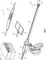
- Fig. 1is a perspective view of the components of one illustrative embodiment of a bipolar and monopolar electrosurgical system 10 according to the present disclosure.
- the system 10may include one or more monopolar electrosurgical instruments 20 having one or more active electrodes 23 (e.g., electrosurgical cutting probe, ablation electrode(s), etc.) for treating tissue of a patient.
- Electrosurgical alternating currentis supplied to the instrument 20 by a generator 200 via a supply line 24 that is connected to an active terminal 230 ( Fig. 3 ) of the generator 200, allowing the instrument 20 to cut, coagulate, ablate and/or otherwise treat tissue.
- the alternating currentis returned to the generator 200 through a return electrode pad 26 via a return line 28 at a return terminal 32 ( Fig.
- the system 10may include a plurality of return electrode pads 26 that, in use, are disposed on a patient to minimize the chances of tissue damage by maximizing the overall contact area with the patient.
- the generator 200 and the return electrode pads 26may be configured for monitoring tissue-to-patient contact to ensure that sufficient contact exists therebetween.
- the system 10may also include one or more bipolar electrosurgical instruments, for example, a bipolar electrosurgical forceps 30 having one or more electrodes for treating tissue of a patient.
- the electrosurgical forceps 30includes a housing 31 and opposing jaw members 33 and 35 disposed at a distal end of a shaft 32.
- the jaw members 33 and 35have one or more active electrodes 34 and a return electrode 36 disposed therein, respectively.
- the active electrode 34 and the return electrode 36are connected to the generator 200 through cable 38 that includes the supply and return lines 24, 28 coupled to the active and return terminals 230, 232, respectively ( Fig. 3 ).
- the electrosurgical forceps 30is coupled to the generator 200 at a connector having connections to the active and return terminals 230 and 232 (e.g., pins) via a plug disposed at the end of the cable 38, wherein the plug includes contacts from the supply and return lines 24, 28 as described in more detail below.
- the generator 200may be any suitable type (e.g., electrosurgical, microwave, etc.) and may include a plurality of connectors 250-262 to accommodate various types of electrosurgical instruments (e.g., electrosurgical forceps 30, etc.).
- electrosurgical instrumentse.g., electrosurgical forceps 30, etc.
- the generator 200includes a user interface 241 having one or more display screens or information panels 242, 244, 246 for providing the user with variety of output information (e.g., intensity settings, treatment complete indicators, etc.). Each of the screens 242, 244, 246 is associated with corresponding connector 250-262.
- the generator 200includes suitable input controls (e.g., buttons, activators, switches, touch screen, etc.) for controlling the generator 200.
- the display screens 242, 244, 246are also configured as touch screens that display a corresponding menu for the electrosurgical instruments (e.g., electrosurgical forceps 30, etc.). The user then adjusts inputs by simply touching corresponding menu options.
- Screen 242controls monopolar output and the devices connected to the connectors 250 and 252.
- Connector 250is configured to couple to a monopolar electrosurgical instrument (e.g., electrosurgical instrument 20) and connector 252 is configured to couple to a foot switch (not shown). The foot switch provides for additional inputs (e.g., replicating inputs of the generator 200).
- Screen 244controls monopolar and bipolar output and the devices connected to the connectors 256 and 258.
- Connector 256is configured to couple to other monopolar instruments.
- Connector 258is configured to couple to a bipolar instrument (not shown).
- Screen 246controls bipolar sealing procedures performed by the forceps 30 that may be plugged into the connectors 260 and 262.
- the generator 200outputs energy through the connectors 260 and 262 suitable for sealing tissue grasped by the forceps 30.
- screen 246outputs a user interface that allows the user to input a user-defined intensity setting.
- the user-defined settingis transmitted to the controller 224 where the setting may be saved in memory 226, and may be any setting that allows the user to adjust one or more energy delivery parameters, such as power, current, voltage, energy, etc. or sealing parameters, such as energy rate limiters, sealing duration, etc..
- the intensity settingmay be a number scale, such as for example, from one to ten or one to five.
- the intensity settingmay be associated with an output curve of the generator 200.
- the intensity settingsmay be specific for each forceps 30 being utilized, such that various instruments provide the user with a specific intensity scale corresponding to the forceps 30.
- Fig. 3shows a schematic block diagram of the generator 200 configured to output electrosurgical energy.
- the generator 200includes a controller 224, a power supply 227, and a radio-frequency (RF) amplifier 228.
- the power supply 227may be a high voltage, DC power supply connected to an AC source (e.g., line voltage) and provides high voltage, DC power to the RF amplifier 228 via leads 227a and 227b, which then converts high voltage, DC power into treatment energy (e.g., electrosurgical or microwave) and delivers the energy to the active terminal 230.
- the output voltagetypically ranges from about 50v to 350v, and is controlled by the HLA via a software target generator 406 ( Fig. 4 ). The energy is returned the generator 200 via the return terminal 232.
- the active and return terminals 230 and 232are coupled to the RF amplifier 228 through an isolation transformer 229.
- the RF amplifier 228is configured to operate in a plurality of modes, during which the generator 200 outputs corresponding waveforms having specific duty cycles, peak voltages, crest factors, etc.
- the RF amplifier 228may be a phase shifted resonant inverter topology, with a pulse width modulator (PWM) input and a high voltage, DC input. Adjustments to the PWM phase control the output energy of the RF amplifier 228 such that minimum energy output is associated with low PWM phase shifts while high energy outputs are associated with high PWM phase shifts.
- PWMpulse width modulator
- the power supply 227acts as a multiplier to the RF amplifier 228 output, wherein a lower power supply value will case the RF amplifier 228 output energy to be lower than the output with the same PWM phase but at a higher power supply value. It is envisioned that in other embodiments, the generator 200 may be based on other types of suitable power supply topologies.
- the controller 224includes a microprocessor 225 operably connected to a memory 226.
- Memory 226may include any non-transitory computer-readable storage media for storing data and/or software that is executable by the microprocessor 225 and which controls the operation of the generator.
- memory 226may include one or more solid-state storage devices such as flash memory chips.
- memory 226may include one or more mass storage devices connected to the microprocessor 225 through a mass storage controller (not shown) and a communications bus (not shown).
- computer-readable mediacan be any available media that can be accessed by the microprocessor 225. That is, computer readable storage media includes non-transitory, volatile and non-volatile, removable and non-removable media implemented in any method or technology for storage of information such as computer-readable instructions, data structures, program modules, or other data.
- computer-readable storage mediaincludes RAM, ROM, EPROM, EEPROM, flash memory or other solid state memory technology, CD-ROM, DVD, BLU-RAY® or any other optical storage, magnetic cassettes, magnetic tape, magnetic disk storage or other magnetic storage devices, or any other medium which can be used to store the desired information and which can be accessed by the generator.
- the microprocessor 225includes an output port that is operably connected to the power supply 227 and/or RF amplifier 228 allowing the microprocessor 225 to control the output of the generator 200 according to either open and/or closed control loop schemes.
- a closed loop control schemeis a feedback control loop, in which a plurality of sensors measure a variety of tissue and energy properties (e.g., tissue impedance, tissue temperature, output power, current and/or voltage, etc.), and provide feedback to the controller 224.
- the controller 224then signals the power supply 227 and/or RF amplifier 228, which adjusts the DC and/or power supply, respectively.
- microprocessor 225may be substituted for by using any logic processor (e.g., control circuit) adapted to perform the calculations and/or set of instructions described herein including, but not limited to, field programmable gate array, digital signal processor, and combinations thereof.
- logic processore.g., control circuit
- the generator 200includes a plurality of sensors 280, e.g., an RF current sensor 280a, and an RF voltage sensor 280b.
- Various components of the generator 200namely, the RF amplifier 228, the RF current and voltage sensors 280a and 280b, may be disposed on a printed circuit board (PCB).
- the RF current sensor 280ais coupled to the active terminal 230 and provides measurements of the RF current supplied by the RF amplifier 228.
- the RF voltage sensor 280bis coupled to the active and return terminals 230 and 232 provides measurements of the RF voltage supplied by the RF amplifier 228.
- the RF current and voltage sensors 280a and 280bmay be coupled to active and return leads 228a and 228b, which interconnect the active and return terminals 230 and 232 to the RF amplifier 228, respectively.
- the RF sensorsrepresent the analog and digital hardware and software required to convert the sensed voltage and current RF waveforms delivered to the patient into the representative current, voltage, and power delivered to the patient, as well as the complex patient load impedance.
- the RF current and voltage sensors 280a and 280bprovide the sensed RF voltage and current signals, respectively, to the controller 224, which then may adjust output of the power supply 227 and/or the RF amplifier 228 in response to the sensed RF voltage and current signals.
- the controller 224also receives input signals from the input controls of the generator 200, the instrument 20, and/or forceps 30. The controller 224 utilizes the input signals to adjust power outputted by the generator 200 and/or performs other control functions.
- HLA engine 404a high level algorithm engine
- interpreted languagerefers to any computer language that is interpreted directly by an interpreter, rather than first being compiled into machine-language instructions.
- the HLA engine 404is a language interpreter configured to execute an interpreted language script (HLA script).
- the HLA engine 404may be implemented in either software executable by the microprocessor 225 or hardware, e.g., microprocessor 225.
- the HLA scriptcontains instructions to be executed by the engine and may include any software instructions, such as an RF delivery algorithm, which may be stored on any suitable computer-readable medium, e.g., memory 226.
- the instructions for performing the various functions of the generatormay be contained in pre-compiled subroutines that are called by the HLA script to be executed.
- the HLA scriptmay not need to include the specific instructions for causing the generator to perform a particular function, and would instead call on these pre-compiled subroutines for executing those functions.
- the usage of an interpreted languageallows the underlying engine to be created and executed on any microprocessor or digital machine, which may then in turn execute the HLA script, thus making the HLA script highly portable and easily replaceable.
- the HLAmay be received by the generator 200 from a download source.
- the download sourcemay be external to the generator 200, such as another computer or server accessible over a network, or internal, such as a memory storage device, for example memory 226 and/or a removable storage medium.
- the download sourcemay be a cloud-based update server or the like.
- a handset for use with the generator 200may incorporate a radio frequency identification (RFID) device, or any other suitable storage medium, which may include its own memory storing a HLA script that the generator 200 may download, and/or instructions to configure the generator to download a particular HLA script from an external source, such as a cloud-based update server.
- the storage mediummay be a barcode including a link to the external source for downloading the HLA.
- the networkmay be any network known to those skilled in the art, such as a local area network (LAN) consisting of a wired network and/or a wireless network, a wide area network (WAN), a wireless mobile network, a BLUETOOTH® network, and/or the Internet.
- LANlocal area network
- WANwide area network
- BLUETOOTH®wireless mobile network
- the generator 200may receive or store, e.g., by preloading, a set of mode configuration files ("CFG files") 402 which control the operation of the generator.
- the CFG files 402contain all the information required to generate a specific form of RF energy, which enables the generator 200 to operate in various RF modes, such as, for example, cut, coag, spray, fulgurate, etc.
- Multiple CFG files 402may be associated with a single HLA, which allows the HLA to use several modes during execution.
- the HLAcan load a specific CFG file 402 to start RF generation, and then monitor the delivered RF and tissue response and during energy application, a new CFG file 402 may be loaded based on sensed tissue or energy properties as needed.
- the HLAmay modify the existing CFG files 402 to modify RF energy delivery, e.g., change mode, adjust amplitude, etc., when a specific tissue event occurs.
- the HLAmay start treatment using a first mode, e.g., a cut RF mode, and, once cutting is completed, the HLA may then load a second mode, e.g., coag RF mode which then cauterizes the tissue.
- HLA engine 404sends instructions to a software target generator (SWC) 406.
- SWC 406controls the programming of a hardware compensator (HWC) 408, and controls target adjustments so that HWC 408 correctly implements a desired RF energy profile specified by the loaded CFG file 402.
- HWC 408is described below as one exemplary embodiment of an RF inverter or output stage and any other suitable inverter may be utilized by the generator 200 according to the present disclosure.
- HWC 408in turn controls RF amplifier 228 based on the loaded CFG file 402 to implement the correct configuration and the desired RF energy output range.
- SWC 406may be implemented as software executable by a microprocessor, and/or implemented as a hardware component.
- HWC 408is designed to adjust the PWM phase shift such that energy is delivered to the patient at the desired RF current, voltage, and/or power. HWC 408 also creates the pulse patterns of the RF waveform.
- Fig. 5a flowchart is shown of a method for using an HLA to operate and control the generator 200 according to the present disclosure. Processing may start at step S502, when the generator 200 receives an HLA. Receiving the HLA may include one or more of loading the HLA from internal storage, loading the HLA from external storage, and/or downloading the HLA from a source external to the generator 200, such as, for example, a computer connected via a network. At step S504, the generator 200 receives one or more CFG files.
- Receiving the CFG filesmay also include one or more of loading the CFG files from internal storage, loading the CFG files from external storage, loading the CFG files from a memory storage device associated with the electrosurgical instrument 20 connected to generator 200, and/or downloading the CFG files from a source external to the generator 200, such as, for example, a computer connected via a network.
- CFG filesmay be preloaded in the generator 200, e.g., memory 226.
- a CFG fileis selected and loaded based on a desired mode of operation.
- a cut operationis desired, a corresponding CFG file may be loaded to implement a RF energy profile to perform a cut operation.
- a corresponding CFG filemay be loaded to implement a RF energy profile to perform a coag operation.
- the HLAis executed by the HLA engine using the loaded CFG file.
- the execution of the HLAin turn, at step S510, controls the power supply 227 and the RF amplifier 228 to generate RF energy according to the RF energy profile associated with the loaded CFG file.
- the generated RF energyis applied to the patient.
- step S514feedback regarding the application of the RF energy to the patient is received by the RF sensors 280. Based on the feedback received by the RF sensors 280, the HLA, at step S516, determines whether a different mode of operation is required. If YES, processing proceeds to step S518. If NO, processing proceeds to step S522. At step S518, the HLA determines whether a different CFG file is required to control the generator 200 to operate in a different mode. If YES, processing returns to step S506 where a new CFG file is selected and loaded based on the desired mode of operation. If NO, processing proceeds to step S520.
- the loaded CFG fileis modified by the HLA to slightly adjust its parameters. For example, based on the feedback received by RF sensors 280, the HLA may determine that the generated RF energy is to be adjusted. In such a case, the HLA may modify the CFG file to adjust the generated RF energy profile instead of loading a new CFG file.
- processingreturns to step S508 where the HLA is executed by the HLA engine using the modified CFG file.
- the generator 200 at step S520may also receive another HLA in response to the detected feedback, thus moving back to S502.
- step S522which is reached if it is determined at step S516 that a different mode of operation is not required, the HLA determines whether additional RF energy generation is required. If YES, processing returns to step S510 where the power supply 227 and the RF amplifier 228 is controlled to generate additional RF energy according to the RF energy profile associated with the loaded CFG file. If NO, processing ends.
Landscapes
- Engineering & Computer Science (AREA)
- Health & Medical Sciences (AREA)
- Surgery (AREA)
- Life Sciences & Earth Sciences (AREA)
- Physics & Mathematics (AREA)
- Medical Informatics (AREA)
- Animal Behavior & Ethology (AREA)
- Nuclear Medicine, Radiotherapy & Molecular Imaging (AREA)
- Biomedical Technology (AREA)
- Heart & Thoracic Surgery (AREA)
- Plasma & Fusion (AREA)
- Molecular Biology (AREA)
- Otolaryngology (AREA)
- General Health & Medical Sciences (AREA)
- Public Health (AREA)
- Veterinary Medicine (AREA)
- General Engineering & Computer Science (AREA)
- General Physics & Mathematics (AREA)
- Automation & Control Theory (AREA)
- Surgical Instruments (AREA)
Description
- The present disclosure relates to a system and method for operating an electrosurgical generator. More particularly, the present disclosure relates to a system, method, and apparatus for using a high level algorithm (HLA) to operate and control an electrosurgical generator.
- Electrosurgery involves application of high radio frequency electrical current to a surgical site to cut, ablate, or coagulate tissue.
- Electrosurgery involves application of high radio frequency electrical current to a surgical site to, e.g., cut, ablate, or coagulate tissue. In monopolar electrosurgery, a source or active electrode delivers radio frequency alternating current from the electrosurgical generator to the targeted tissue. A patient return electrode is placed remotely from the active electrode to conduct the current back to the generator.
- In bipolar electrosurgery, return and active electrodes are placed in close proximity to each other such that an electrical circuit is formed between the two electrodes (e.g., in the case of an electrosurgical forceps). In this manner, the applied electrical current is limited to the body tissue positioned between the electrodes. Accordingly, bipolar electrosurgery generally involves the use of instruments where it is desired to achieve a focused delivery of electrosurgical energy between two electrodes positioned on the instrument, e.g. forceps or the like. A forceps is a pliers-like instrument which relies on mechanical action between its jaws to grasp, clamp, and constrict vessels or tissue. Electrosurgical forceps (open or endoscopic) utilize mechanical clamping action and electrical energy to affect hemostasis on the clamped tissue. The forceps include electrosurgical conductive surfaces which apply the electrosurgical energy to the clamped tissue. By controlling the intensity, frequency, and duration of the electrosurgical energy applied through the conductive plates to the tissue, the surgeon can, for example, coagulate, cauterize, and/or seal tissue. However, the above example is for illustrative purposes only and there are many other known bipolar electrosurgical instruments which are within the scope of the present disclosure.
- The electrosurgical procedures outlined above may utilize various tissue and energy parameters in a feedback-based control system. In electrosurgery, there is a continual need to improve delivery of energy to the tissue.
US 2009/0248007 discloses an electrosurgical generator that supplies RF energy to a connected electrosurgical tool. The tool has memory integrated with or removable from the tool. A tool algorithm or script within the tool's memory is loaded into a script interpreter of the generator. The script provides commands and parameters readying the tool for use when connected to the generator. Upon activation of a switch coupled to the tool, the controller detects the switch closure, and authenticates the tool, checks the tool's expiration status, and initializes internal data structures representing the receptacle's tool. A subsequent activation of the tool switch initiates an event that causes the script to direct the generator to supply RF energy. - The invention is defined in the claims. Any method
disclosed herein does not form part of the scope of the invention. - According to one embodiment, the present disclosure provides for a method for operating an electro surgical generator.
- In an aspect of the present disclosure, the method includes receiving a high level algorithm at an electrosurgical generator including a processor, a power supply, and a radio frequency amplifier, the high level algorithm including an interpreted language script, processing the interpreted language script through an interpreter engine executed by the processor, selecting at least one of a plurality of configuration files stored in the electrosurgical generator based on the interpreted language script to effect a desired mode of operation, and executing the interpreted language script based on the selected one of the plurality of configuration files to generate instructions which cause the electrosurgical generator to control at least one of the power supply and the radio frequency amplifier to generate radio frequency energy according to the selected one of the plurality of configuration files.
- In another aspect of the present disclosure, the method includes measuring, at a sensor coupled to the radio frequency amplifier, at least one property of the radio frequency energy.
- In a further aspect of the present disclosure, the method includes selecting another mode of operation based on the at least one property of the radio frequency energy.
- In yet a further aspect of the present disclosure, the method includes selecting a second one of the plurality of configuration files based on the selected another mode of operation.
- In a still further aspect of the present disclosure, the method includes selecting the second one of the plurality of configuration files based on the interpreted language script to effect the selected another mode of operation, and executing the interpreted language script based on the selected second one of the plurality of configuration files to generate instructions which cause the electrosurgical generator to control at least one of the power supply and the radio frequency amplifier to generate radio frequency energy according to the selected second one of the plurality of configuration files.
- In another aspect of the present disclosure, the method includes modifying the selected one of the plurality of configuration files to generate a modified configuration file, and executing the interpreted language script based on the modified configuration file to generate instructions which cause the electrosurgical generator to control at least one of the power supply and the radio frequency amplifier to generate radio frequency energy according to the modified configuration file.
- According to another embodiment, the present disclosure provides for a system for operating an electrosurgical generator.
- In an aspect of the present disclosure, the system includes an external download source configured to provide a high level algorithm to the electrosurgical generator, and the electrosurgical generator including a power supply, a radio frequency amplifier, a processor, and a memory, the processor configured to receive the high level algorithm from the external download source, the high level algorithm including an interpreted language script, process the interpreted language script through an interpreter engine executed by the processor, select at least one of a plurality of configuration files stored in the memory based on the interpreted language script to effect a desired mode of operation, and execute the interpreted language script based on the selected on of the plurality of configuration files to generate instructions which cause the electrosurgical generator to control at least one of the power supply and the radio frequency amplifier to generate radio frequency energy according to the selected one of the plurality of configuration files.
- In another aspect of the present disclosure, the electrosurgical generator further includes a sensor coupled to the radio frequency amplifier, the sensor configured to measure at least one property of the radio frequency energy.
- In a further aspect of the present disclosure, the processor is further configured to select another mode of operation based on the at least one property of the radio frequency energy.
- In yet a further aspect of the present disclosure, the processor is further configured to select a second one of the plurality of configuration files based on the selected another mode of operation.
- In still a further aspect of the present disclosure, the processor is further configured to select the second one of the plurality of configuration files based on the interpreted language script to effect the another mode of operation, and execute the interpreted language script based on the selected second one of the plurality of configuration files to generate instructions which cause the electrosurgical generator to control at least one of the power supply and the radio frequency amplifier to generate radio frequency energy according to the selected second one of the plurality of configuration files.
- In another aspect of the present disclosure, the processor is further configured to modify the selected one of the plurality of configuration files to generate a modified configuration file, and execute the interpreted language script based on the modified configuration file to generate instructions which cause the electrosurgical generator to control at least one of the power supply and the radio frequency amplifier to generate radio frequency energy according to the modified configuration file.
- According to another embodiment, the present disclosure provides for an electrosurgical generator.
- In an aspect of the present disclosure, the electrosurgical generator includes a power supply, a radio frequency amplifier, a processor, and a memory, the processor configured to receive a high level algorithm, the high level algorithm including an interpreted language script, process the interpreted language script through an interpreter engine executed by the processor, select at least one of a plurality of configuration files stored in the memory based on the interpreted language script to effect a desired mode of operation, and execute the interpreted language script based on the selected one of the plurality of configuration files to generate instructions which cause the electrosurgical generator to control at least one of the power supply and the radio frequency amplifier to generate radio frequency energy according to the selected one of the plurality of configuration files.
- In another aspect of the present disclosure, the electrosurgical generator further includes a sensor coupled to the radio frequency amplifier, the sensor configured to measure at least one property of the radio frequency energy.
- In a further aspect of the present disclosure, the processor is further configured to select another mode of operation based on at least one property of the radio frequency energy.
- In yet a further aspect of the present disclosure, the processor is further configured to select a second one of the plurality of configuration files based on the selected another mode of operation.
- In still a further aspect of the present disclosure, the processor is further configured to select the second one of the plurality of configuration files based on the interpreted language script to effect the another mode of operation, and execute the interpreted language script based on the selected second one of the plurality of configuration files to generate instructions which cause the electrosurgical generator to control at least one of the power supply and the radio frequency amplifier to generate radio frequency energy according to the selected second one of the plurality of configuration files.
- In another aspect of the present disclosure, the processor is further configured to modify the selected one of the plurality of configuration files to generate a modified configuration file, and execute the interpreted language script based on the modified configuration file to generate instructions which cause the electrosurgical generator to control at least one of the power supply and the radio frequency amplifier to generate radio frequency energy according to the modified configuration file.
- In another aspect of the present disclosure, the processor is further configured to modify to select another mode of operation based on at least one of user input or an identifier associated with an instrument coupled to the power supply. The identifier may be a barcode, a radio frequency identification tag, or a storage device.
- Any of the above aspects and embodiments of the present disclosure may be combined without departing from the scope of the present disclosure.
- Various illustrative embodiments of the present disclosure are described herein with reference to the drawings wherein:
Fig. 1 is a perspective view of the components of an electrosurgical system according to one illustrative embodiment of the present disclosure;Fig. 2 is a front view of one embodiment of an electrosurgical generator according to an illustrative embodiment of the present disclosure;Fig. 3 is a schematic, block diagram of the embodiment of an electrosurgical generator ofFig. 2 ;Fig. 4 is a flowchart of an illustrative configuration of the electrosurgical generator ofFig. 2 using a high level algorithm; andFig. 5 is a flowchart of a method for operating the electrosurgical generator ofFig. 2 using the high level algorithm ofFig. 4 .- Particular embodiments of the present disclosure are described below with reference to the accompanying drawings. In the following description, well-known functions or constructions are not described in detail to avoid obscuring the present disclosure in unnecessary detail.
- The present disclosure provides for systems and methods for operating an electrosurgical generator to perform any suitable electrosurgical procedure. The generator may include a plurality of outputs for interfacing with various electrosurgical instruments (e.g., a monopolar instrument, return electrode, bipolar electrosurgical forceps, footswitch, etc.). Further, the generator includes electronic circuitry configured to generate radio frequency energy specifically suited for various electrosurgical modes (e.g., cut, blend, coagulate, division with hemostasis, fulgurate, spray, etc.) and procedures (e.g., vessel sealing). In embodiments, the generator may be embedded, integrated, or otherwise coupled to the electrosurgical instruments providing for an all-in-one electrosurgical apparatus. The generator may be configured to receive a high level algorithm (HLA) which may be executable by an HLA Engine incorporated within the electrosurgical generator, allowing the electrosurgical generator to modify its operation in real-time
Fig. 1 is a perspective view of the components of one illustrative embodiment of a bipolar and monopolarelectrosurgical system 10 according to the present disclosure. Thesystem 10 may include one or more monopolarelectrosurgical instruments 20 having one or more active electrodes 23 (e.g., electrosurgical cutting probe, ablation electrode(s), etc.) for treating tissue of a patient. Electrosurgical alternating current is supplied to theinstrument 20 by agenerator 200 via asupply line 24 that is connected to an active terminal 230 (Fig. 3 ) of thegenerator 200, allowing theinstrument 20 to cut, coagulate, ablate and/or otherwise treat tissue. The alternating current is returned to thegenerator 200 through areturn electrode pad 26 via areturn line 28 at a return terminal 32 (Fig. 3 ) of thegenerator 200. For monopolar operation, thesystem 10 may include a plurality ofreturn electrode pads 26 that, in use, are disposed on a patient to minimize the chances of tissue damage by maximizing the overall contact area with the patient. In addition, thegenerator 200 and thereturn electrode pads 26 may be configured for monitoring tissue-to-patient contact to ensure that sufficient contact exists therebetween.- The
system 10 may also include one or more bipolar electrosurgical instruments, for example, a bipolarelectrosurgical forceps 30 having one or more electrodes for treating tissue of a patient. Theelectrosurgical forceps 30 includes ahousing 31 and opposingjaw members shaft 32. Thejaw members active electrodes 34 and areturn electrode 36 disposed therein, respectively. Theactive electrode 34 and thereturn electrode 36 are connected to thegenerator 200 throughcable 38 that includes the supply and returnlines terminals Fig. 3 ). Theelectrosurgical forceps 30 is coupled to thegenerator 200 at a connector having connections to the active and returnterminals 230 and 232 (e.g., pins) via a plug disposed at the end of thecable 38, wherein the plug includes contacts from the supply and returnlines - With reference to
Fig. 2 , a front face 240 of thegenerator 200 is shown. Thegenerator 200 may be any suitable type (e.g., electrosurgical, microwave, etc.) and may include a plurality of connectors 250-262 to accommodate various types of electrosurgical instruments (e.g.,electrosurgical forceps 30, etc.). - The
generator 200 includes auser interface 241 having one or more display screens orinformation panels screens generator 200 includes suitable input controls (e.g., buttons, activators, switches, touch screen, etc.) for controlling thegenerator 200. The display screens 242, 244, 246 are also configured as touch screens that display a corresponding menu for the electrosurgical instruments (e.g.,electrosurgical forceps 30, etc.). The user then adjusts inputs by simply touching corresponding menu options. Screen 242 controls monopolar output and the devices connected to theconnectors Connector 250 is configured to couple to a monopolar electrosurgical instrument (e.g., electrosurgical instrument 20) andconnector 252 is configured to couple to a foot switch (not shown). The foot switch provides for additional inputs (e.g., replicating inputs of the generator 200).Screen 244 controls monopolar and bipolar output and the devices connected to theconnectors Connector 256 is configured to couple to other monopolar instruments.Connector 258 is configured to couple to a bipolar instrument (not shown).Screen 246 controls bipolar sealing procedures performed by theforceps 30 that may be plugged into theconnectors generator 200 outputs energy through theconnectors forceps 30. In particular,screen 246 outputs a user interface that allows the user to input a user-defined intensity setting. The user-defined setting is transmitted to thecontroller 224 where the setting may be saved inmemory 226, and may be any setting that allows the user to adjust one or more energy delivery parameters, such as power, current, voltage, energy, etc. or sealing parameters, such as energy rate limiters, sealing duration, etc.. In embodiments, the intensity setting may be a number scale, such as for example, from one to ten or one to five. In embodiments, the intensity setting may be associated with an output curve of thegenerator 200. The intensity settings may be specific for eachforceps 30 being utilized, such that various instruments provide the user with a specific intensity scale corresponding to theforceps 30.Fig. 3 shows a schematic block diagram of thegenerator 200 configured to output electrosurgical energy. Thegenerator 200 includes acontroller 224, apower supply 227, and a radio-frequency (RF)amplifier 228. Thepower supply 227 may be a high voltage, DC power supply connected to an AC source (e.g., line voltage) and provides high voltage, DC power to theRF amplifier 228 vialeads active terminal 230. The output voltage typically ranges from about 50v to 350v, and is controlled by the HLA via a software target generator 406 (Fig. 4 ). The energy is returned thegenerator 200 via thereturn terminal 232. The active and returnterminals RF amplifier 228 through an isolation transformer 229. TheRF amplifier 228 is configured to operate in a plurality of modes, during which thegenerator 200 outputs corresponding waveforms having specific duty cycles, peak voltages, crest factors, etc. TheRF amplifier 228 may be a phase shifted resonant inverter topology, with a pulse width modulator (PWM) input and a high voltage, DC input. Adjustments to the PWM phase control the output energy of theRF amplifier 228 such that minimum energy output is associated with low PWM phase shifts while high energy outputs are associated with high PWM phase shifts. Thepower supply 227 acts as a multiplier to theRF amplifier 228 output, wherein a lower power supply value will case theRF amplifier 228 output energy to be lower than the output with the same PWM phase but at a higher power supply value. It is envisioned that in other embodiments, thegenerator 200 may be based on other types of suitable power supply topologies.- The
controller 224 includes amicroprocessor 225 operably connected to amemory 226.Memory 226 may include any non-transitory computer-readable storage media for storing data and/or software that is executable by themicroprocessor 225 and which controls the operation of the generator. In an embodiment,memory 226 may include one or more solid-state storage devices such as flash memory chips. Alternatively, or in addition to the one or more solid-state storage devices,memory 226 may include one or more mass storage devices connected to themicroprocessor 225 through a mass storage controller (not shown) and a communications bus (not shown). Although the description of computer-readable media contained herein refers to a solid-state storage, it should be appreciated by those skilled in the art that computer-readable storage media can be any available media that can be accessed by themicroprocessor 225. That is, computer readable storage media includes non-transitory, volatile and non-volatile, removable and non-removable media implemented in any method or technology for storage of information such as computer-readable instructions, data structures, program modules, or other data. For example, computer-readable storage media includes RAM, ROM, EPROM, EEPROM, flash memory or other solid state memory technology, CD-ROM, DVD, BLU-RAY® or any other optical storage, magnetic cassettes, magnetic tape, magnetic disk storage or other magnetic storage devices, or any other medium which can be used to store the desired information and which can be accessed by the generator. - The
microprocessor 225 includes an output port that is operably connected to thepower supply 227 and/orRF amplifier 228 allowing themicroprocessor 225 to control the output of thegenerator 200 according to either open and/or closed control loop schemes. A closed loop control scheme is a feedback control loop, in which a plurality of sensors measure a variety of tissue and energy properties (e.g., tissue impedance, tissue temperature, output power, current and/or voltage, etc.), and provide feedback to thecontroller 224. Thecontroller 224 then signals thepower supply 227 and/orRF amplifier 228, which adjusts the DC and/or power supply, respectively. Those skilled in the art will appreciate that themicroprocessor 225 may be substituted for by using any logic processor (e.g., control circuit) adapted to perform the calculations and/or set of instructions described herein including, but not limited to, field programmable gate array, digital signal processor, and combinations thereof. - The
generator 200 according to the present disclosure includes a plurality ofsensors 280, e.g., an RFcurrent sensor 280a, and anRF voltage sensor 280b. Various components of thegenerator 200, namely, theRF amplifier 228, the RF current andvoltage sensors current sensor 280a is coupled to theactive terminal 230 and provides measurements of the RF current supplied by theRF amplifier 228. TheRF voltage sensor 280b is coupled to the active and returnterminals RF amplifier 228. In embodiments, the RF current andvoltage sensors terminals RF amplifier 228, respectively. The RF sensors represent the analog and digital hardware and software required to convert the sensed voltage and current RF waveforms delivered to the patient into the representative current, voltage, and power delivered to the patient, as well as the complex patient load impedance. - The RF current and
voltage sensors controller 224, which then may adjust output of thepower supply 227 and/or theRF amplifier 228 in response to the sensed RF voltage and current signals. Thecontroller 224 also receives input signals from the input controls of thegenerator 200, theinstrument 20, and/orforceps 30. Thecontroller 224 utilizes the input signals to adjust power outputted by thegenerator 200 and/or performs other control functions. - With reference to
Fig. 4 , a flowchart of a method for using a HLA to operate and control theelectrosurgical generator 200 according to the present disclosure is shown. Elements and structures with the same function as shown inFigs. 1-3 are numbered the same and will not be described again for purpose of brevity. The HLA may be written in an interpreted language which can be executed by a high level algorithm engine (HLA engine) 404. As used herein, "interpreted language" refers to any computer language that is interpreted directly by an interpreter, rather than first being compiled into machine-language instructions. TheHLA engine 404 is a language interpreter configured to execute an interpreted language script (HLA script). TheHLA engine 404 may be implemented in either software executable by themicroprocessor 225 or hardware, e.g.,microprocessor 225. The HLA script contains instructions to be executed by the engine and may include any software instructions, such as an RF delivery algorithm, which may be stored on any suitable computer-readable medium, e.g.,memory 226. The instructions for performing the various functions of the generator may be contained in pre-compiled subroutines that are called by the HLA script to be executed. Thus, the HLA script may not need to include the specific instructions for causing the generator to perform a particular function, and would instead call on these pre-compiled subroutines for executing those functions. The usage of an interpreted language allows the underlying engine to be created and executed on any microprocessor or digital machine, which may then in turn execute the HLA script, thus making the HLA script highly portable and easily replaceable. - The HLA may be received by the
generator 200 from a download source. The download source may be external to thegenerator 200, such as another computer or server accessible over a network, or internal, such as a memory storage device, forexample memory 226 and/or a removable storage medium. Alternatively, the download source may be a cloud-based update server or the like. A handset for use with thegenerator 200 may incorporate a radio frequency identification (RFID) device, or any other suitable storage medium, which may include its own memory storing a HLA script that thegenerator 200 may download, and/or instructions to configure the generator to download a particular HLA script from an external source, such as a cloud-based update server. In embodiments, the storage medium may be a barcode including a link to the external source for downloading the HLA. The network may be any network known to those skilled in the art, such as a local area network (LAN) consisting of a wired network and/or a wireless network, a wide area network (WAN), a wireless mobile network, a BLUETOOTH® network, and/or the Internet. - In addition to the HLA, the
generator 200 may receive or store, e.g., by preloading, a set of mode configuration files ("CFG files") 402 which control the operation of the generator. The CFG files 402 contain all the information required to generate a specific form of RF energy, which enables thegenerator 200 to operate in various RF modes, such as, for example, cut, coag, spray, fulgurate, etc. Multiple CFG files 402 may be associated with a single HLA, which allows the HLA to use several modes during execution. The HLA can load aspecific CFG file 402 to start RF generation, and then monitor the delivered RF and tissue response and during energy application, anew CFG file 402 may be loaded based on sensed tissue or energy properties as needed. In embodiments, to enter a different RF mode, the HLA may modify the existing CFG files 402 to modify RF energy delivery, e.g., change mode, adjust amplitude, etc., when a specific tissue event occurs. In further embodiments, during execution, the HLA may start treatment using a first mode, e.g., a cut RF mode, and, once cutting is completed, the HLA may then load a second mode, e.g., coag RF mode which then cauterizes the tissue. - During execution of the HLA in conjunction with the CFG files 402,
HLA engine 404 sends instructions to a software target generator (SWC) 406.SWC 406 controls the programming of a hardware compensator (HWC) 408, and controls target adjustments so thatHWC 408 correctly implements a desired RF energy profile specified by the loadedCFG file 402.HWC 408 is described below as one exemplary embodiment of an RF inverter or output stage and any other suitable inverter may be utilized by thegenerator 200 according to the present disclosure.HWC 408 in turn controlsRF amplifier 228 based on the loadedCFG file 402 to implement the correct configuration and the desired RF energy output range.SWC 406 may be implemented as software executable by a microprocessor, and/or implemented as a hardware component.HWC 408 is designed to adjust the PWM phase shift such that energy is delivered to the patient at the desired RF current, voltage, and/or power.HWC 408 also creates the pulse patterns of the RF waveform. Referring now toFig. 5 , a flowchart is shown of a method for using an HLA to operate and control thegenerator 200 according to the present disclosure. Processing may start at step S502, when thegenerator 200 receives an HLA. Receiving the HLA may include one or more of loading the HLA from internal storage, loading the HLA from external storage, and/or downloading the HLA from a source external to thegenerator 200, such as, for example, a computer connected via a network. At step S504, thegenerator 200 receives one or more CFG files. Receiving the CFG files may also include one or more of loading the CFG files from internal storage, loading the CFG files from external storage, loading the CFG files from a memory storage device associated with theelectrosurgical instrument 20 connected togenerator 200, and/or downloading the CFG files from a source external to thegenerator 200, such as, for example, a computer connected via a network. In embodiments, CFG files may be preloaded in thegenerator 200, e.g.,memory 226. Thereafter, at step S506, a CFG file is selected and loaded based on a desired mode of operation. In one aspect of the present disclosure, if a cut operation is desired, a corresponding CFG file may be loaded to implement a RF energy profile to perform a cut operation. Alternatively, if a coag operation is desired, a corresponding CFG file may be loaded to implement a RF energy profile to perform a coag operation. - At step S508, the HLA is executed by the HLA engine using the loaded CFG file. The execution of the HLA in turn, at step S510, controls the
power supply 227 and theRF amplifier 228 to generate RF energy according to the RF energy profile associated with the loaded CFG file. At step S512, the generated RF energy is applied to the patient. - At step S514, feedback regarding the application of the RF energy to the patient is received by the
RF sensors 280. Based on the feedback received by theRF sensors 280, the HLA, at step S516, determines whether a different mode of operation is required. If YES, processing proceeds to step S518. If NO, processing proceeds to step S522. At step S518, the HLA determines whether a different CFG file is required to control thegenerator 200 to operate in a different mode. If YES, processing returns to step S506 where a new CFG file is selected and loaded based on the desired mode of operation. If NO, processing proceeds to step S520. - At step S520, the loaded CFG file is modified by the HLA to slightly adjust its parameters. For example, based on the feedback received by
RF sensors 280, the HLA may determine that the generated RF energy is to be adjusted. In such a case, the HLA may modify the CFG file to adjust the generated RF energy profile instead of loading a new CFG file. After the CFG file has been modified, processing returns to step S508 where the HLA is executed by the HLA engine using the modified CFG file. In embodiments, thegenerator 200 at step S520 may also receive another HLA in response to the detected feedback, thus moving back to S502. - At step S522, which is reached if it is determined at step S516 that a different mode of operation is not required, the HLA determines whether additional RF energy generation is required. If YES, processing returns to step S510 where the
power supply 227 and theRF amplifier 228 is controlled to generate additional RF energy according to the RF energy profile associated with the loaded CFG file. If NO, processing ends. - While several embodiments of the disclosure have been shown in the drawings and/or described herein, it is not intended that the disclosure be limited thereto, as it is intended that the disclosure be as broad in scope as the art will allow and that the specification be read likewise. Therefore, the above description should not be construed as limiting, but merely as exemplifications of particular embodiments. Those skilled in the art will envision other modifications within the scope and spirit of the claims appended hereto.
- The invention may be described by reference to the following numbered paragraphs:-
- 1. A method for operating an electrosurgical generator, the method comprising:
- receiving a high level algorithm at an electrosurgical generator including a processor, a power supply, and a radio frequency amplifier, the high level algorithm including an interpreted language script;
- processing the interpreted language script through an interpreter engine executed by the processor;
- selecting at least one of a plurality of configuration files stored in the electrosurgical generator based on the interpreted language script to effect a desired mode of operation; and
- executing the interpreted language script based on the selected one of the plurality of configuration files to generate instructions which cause the electrosurgical generator to control at least one of the power supply and the radio frequency amplifier to generate radio frequency energy according to the selected one of the plurality of configuration files.
- 2. The method according to
paragraph 1, further comprising measuring, at a sensor coupled to the radio frequency amplifier, at least one property of the radio frequency energy. - 3. The method according to
paragraph 2, further comprising selecting another mode of operation based on the at least one property of the radio frequency energy. - 4. The method according to paragraph 3, wherein selecting one of a plurality of configuration files includes selecting a second one of the plurality of configuration files based on the selected another mode of operation.
- 5. The method according to paragraph 4, further comprising:
- selecting the second one of the plurality of configuration files based on the interpreted language script to effect the selected another mode of operation; and
- executing the interpreted language script based on the selected second one of the plurality of configuration files to generate instructions which cause the electrosurgical generator to control at least one of the power supply and the radio frequency amplifier to generate radio frequency energy according to the selected second one of the plurality of configuration files.
- 6. The method according to
paragraph 1, further comprising:- modifying the selected one of the plurality of configuration files to generate a modified configuration file; and
- executing the interpreted language script based on the modified configuration file to generate instructions which cause the electrosurgical generator to control at least one of the power supply and the radio frequency amplifier to generate radio frequency energy according to the modified configuration file.
- 7. A system for operating an electrosurgical generator, the system comprising:
- an external download source configured to provide a high level algorithm to the electrosurgical generator; and
- the electrosurgical generator including a power supply, a radio frequency amplifier, a processor, and a memory, the processor configured to:
- receive the high level algorithm from the external download source, the high level algorithm including an interpreted language script;
- process the interpreted language script through an interpreter engine executed by the processor;
- select at least one of a plurality of configuration files stored in the memory based on the interpreted language script to effect a desired mode of operation; and
- execute the interpreted language script based on the selected on of the plurality of configuration files to generate instructions which cause the electrosurgical generator to control at least one of the power supply and the radio frequency amplifier to generate radio frequency energy according to the selected one of the plurality of configuration files.
- 8. The system according to paragraph 7, wherein the electrosurgical generator further includes a sensor coupled to the radio frequency amplifier, the sensor configured to measure at least one property of the radio frequency energy.
- 9. The system according to paragraph 8, wherein the processor is further configured to select another mode of operation based on the at least one property of the radio frequency energy.
- 10. The system according to paragraph 9, wherein selecting one of a plurality of configuration files includes selecting a second one of the plurality of configuration files based on the selected another mode of operation.
- 11. The system according to
paragraph 10, wherein the processor is further configured to:- select the second one of the plurality of configuration files based on the interpreted language script to effect the another mode of operation; and
- execute the interpreted language script based on the selected second one of the plurality of configuration files to generate instructions which cause the electrosurgical generator to control at least one of the power supply and the radio frequency amplifier to generate radio frequency energy according to the selected second one of the plurality of configuration files.
- 12. The system according to paragraph 7, wherein the processor is further configured to:
- modify the selected one of the plurality of configuration files to generate a modified configuration file; and
- execute the interpreted language script based on the modified configuration file to generate instructions which cause the electrosurgical generator to control at least one of the power supply and the radio frequency amplifier to generate radio frequency energy according to the modified configuration file.
- 13. An electrosurgical generator comprising:
a power supply, a radio frequency amplifier, a processor, and a memory, the processor configured to:- receive a high level algorithm, the high level algorithm including an interpreted language script;
- process the interpreted language script through an interpreter engine executed by the processor;
- select at least one of a plurality of configuration files stored in the memory based on the interpreted language script to effect a desired mode of operation; and
- execute the interpreted language script based on the selected one of the plurality of configuration files to generate instructions which cause the electrosurgical generator to control at least one of the power supply and the radio frequency amplifier to generate radio frequency energy according to the selected one of the plurality of configuration files.
- 14. The electrosurgical generator according to paragraph 13, further comprising a sensor coupled to the radio frequency amplifier, the sensor configured to measure at least one property of the radio frequency energy.
- 15. The electrosurgical generator according to paragraph 14, wherein the processor is further configured to select another mode of operation based on at least one property of the radio frequency energy.
- 16. The electrosurgical generator according to paragraph 15, wherein selecting one of a plurality of configuration files includes selecting a second one of the plurality of configuration files based on the selected another mode of operation.
- 17. The electrosurgical generator according to paragraph 16, wherein the processor is further configured to:
- select the second one of the plurality of configuration files based on the interpreted language script to effect the another mode of operation; and
- execute the interpreted language script based on the selected second one of the plurality of configuration files to generate instructions which cause the electrosurgical generator to control at least one of the power supply and the radio frequency amplifier to generate radio frequency energy according to the selected second one of the plurality of configuration files.
- 18. The electrosurgical generator according to paragraph 13, wherein processor is further configured to:
- modify the selected one of the plurality of configuration files to generate a modified configuration file; and
- execute the interpreted language script based on the modified configuration file to generate instructions which cause the electrosurgical generator to control at least one of the power supply and the radio frequency amplifier to generate radio frequency energy according to the modified configuration file.
- 19. The electrosurgical generator according to paragraph 13, wherein the processor is further configured to select another mode of operation based on at least one of user input or an identifier associated with an instrument coupled to the power supply.
- 20. The electrosurgical generator according to paragraph 13, wherein the identifier is selected from the group consisting of a barcode, a radio frequency identification tag, and a storage device.
Claims (15)
- An electrosurgical generator (200) comprising:
a power supply (227), a radio frequency amplifier (228), a processor (225), and a memory (226), the processor configured to:receive a high level algorithm, the high level algorithm including an interpreted language script;process the interpreted language script through an interpreter engine (404) executed by the processor;select at least one of a plurality of configuration files (402) stored in the memory based on the interpreted language script to effect a desired mode of operation; andexecute the interpreted language script based on the selected one of the plurality of configuration files to generate instructions which cause the electrosurgical generator to control at least one of the power supply and the radio frequency amplifier to generate radio frequency energy according to the selected one of the plurality of configuration files. - The electrosurgical generator according to claim 1, further comprising a sensor coupled to the radio frequency amplifier, the sensor configured to measure at least one property of the radio frequency energy, preferably wherein the processor is further configured to select another mode of operation based on at least one property of the radio frequency energy.
- The electrosurgical generator according to claim 2, wherein selecting one of a plurality of configuration files includes selecting a second one of the plurality of configuration files based on the selected another mode of operation.
- The electrosurgical generator according to claim 3, wherein the processor is further configured to:select the second one of the plurality of configuration files based on the interpreted language script to effect the another mode of operation; andexecute the interpreted language script based on the selected second one of the plurality of configuration files to generate instructions which cause the electrosurgical generator to control at least one of the power supply and the radio frequency amplifier to generate radio frequency energy according to the selected second one of the plurality of configuration files.
- The electrosurgical generator according to any one of claims 1 to 4, wherein processor is further configured to:modify the selected one of the plurality of configuration files to generate a modified configuration file; andexecute the interpreted language script based on the modified configuration file to generate instructions which cause the electrosurgical generator to control at least one of the power supply and the radio frequency amplifier to generate radio frequency energy according to the modified configuration file.
- The electrosurgical generator according to any preceding claim, wherein the processor is further configured to select another mode of operation based on at least one of user input or an identifier associated with an instrument coupled to the power supply, preferably wherein the identifier is selected from the group consisting of a barcode, a radio frequency identification tag, and a storage device.
- A system for operating an electrosurgical generator according to claim 6, the system comprising:an external download source configured to provide the high level algorithm to the electrosurgical generator; andthe processor configured to:
receive the high level algorithm from the external download source. - The system according to claim 7, wherein the electrosurgical generator further includes a sensor (280) coupled to the radio frequency amplifier, the sensor configured to measure at least one property of the radio frequency energy, preferably wherein the processor is further configured to select another mode of operation based on the at least one property of the radio frequency energy.
- The system according to claim 8, wherein selecting one of a plurality of configuration files includes selecting a second one of the plurality of configuration files based on the selected another mode of operation, preferably wherein the processor is further configured to:select the second one of the plurality of configuration files based on the interpreted language script to effect the another mode of operation; andexecute the interpreted language script based on the selected second one of the plurality of configuration files to generate instructions which cause the electrosurgical generator to control at least one of the power supply and the radio frequency amplifier to generate radio frequency energy according to the selected second one of the plurality of configuration files.
- The system according to claim 8 or 9, wherein the processor is further configured to:modify the selected one of the plurality of configuration files to generate a modified configuration file; andexecute the interpreted language script based on the modified configuration file to generate instructions which cause the electrosurgical generator to control at least one of the power supply and the radio frequency amplifier to generate radio frequency energy according to the modified configuration file.
- Non-transitory computer readable storage media storing software executable by a microprocessor to control operation of an electrosurgical generator according to a method comprising:receiving a high level algorithm at the electrosurgical generator (200) including the processor (225), a power supply (227), and a radio frequency amplifier (228), the high level algorithm including an interpreted language script;processing the interpreted language script through an interpreter engine (404) executed by the processor;selecting at least one of a plurality of configuration files (402) stored in the electrosurgical generator based on the interpreted language script to effect a desired mode of operation; andexecuting the interpreted language script based on the selected one of the plurality of configuration files to generate instructions which cause the electrosurgical generator to control at least one of the power supply and the radio frequency amplifier to generate radio frequency energy according to the selected one of the plurality of configuration files.
- Non-transitory computer readable storage media according to claim 11, the method further comprising measuring, at a sensor (280) coupled to the radio frequency amplifier, at least one property of the radio frequency energy.
- Non-transitory computer readable storage media according to claim 12, the method further comprising selecting another mode of operation based on the at least one property of the radio frequency energy preferably wherein selecting one of a plurality of configuration files includes selecting a second one of the plurality of configuration files based on the selected another mode of operation.
- Non-transitory computer readable storage media according to claim 13, the method further comprising:selecting the second one of the plurality of configuration files based on the interpreted language script to effect the selected another mode of operation; andexecuting the interpreted language script based on the selected second one of the plurality of configuration files to generate instructions which cause the electrosurgical generator to control at least one of the power supply and the radio frequency amplifier to generate radio frequency energy according to the selected second one of the plurality of configuration files.
- Non-transitory computer readable storage media according to any of claims 11 to 14, the method further comprising:modifying the selected one of the plurality of configuration files to generate a modified configuration file; andexecuting the interpreted language script based on the modified configuration file to generate instructions which cause the electrosurgical generator to control at least one of the power supply and the radio frequency amplifier to generate radio frequency energy according to the modified configuration file.
Priority Applications (1)
| Application Number | Priority Date | Filing Date | Title |
|---|---|---|---|
| EP17184809.6AEP3281595B1 (en) | 2014-12-02 | 2015-10-23 | High level algorithms |
Applications Claiming Priority (1)
| Application Number | Priority Date | Filing Date | Title |
|---|---|---|---|
| US14/557,612US9782212B2 (en) | 2014-12-02 | 2014-12-02 | High level algorithms |
Related Child Applications (2)
| Application Number | Title | Priority Date | Filing Date |
|---|---|---|---|
| EP17184809.6ADivisionEP3281595B1 (en) | 2014-12-02 | 2015-10-23 | High level algorithms |
| EP17184809.6ADivision-IntoEP3281595B1 (en) | 2014-12-02 | 2015-10-23 | High level algorithms |
Publications (2)
| Publication Number | Publication Date |
|---|---|
| EP3028657A1 EP3028657A1 (en) | 2016-06-08 |
| EP3028657B1true EP3028657B1 (en) | 2018-05-16 |
Family
ID=54360176
Family Applications (2)
| Application Number | Title | Priority Date | Filing Date |
|---|---|---|---|
| EP15191293.8AActiveEP3028657B1 (en) | 2014-12-02 | 2015-10-23 | High level algorithms |
| EP17184809.6AActiveEP3281595B1 (en) | 2014-12-02 | 2015-10-23 | High level algorithms |
Family Applications After (1)
| Application Number | Title | Priority Date | Filing Date |
|---|---|---|---|
| EP17184809.6AActiveEP3281595B1 (en) | 2014-12-02 | 2015-10-23 | High level algorithms |
Country Status (2)
| Country | Link |
|---|---|
| US (1) | US9782212B2 (en) |
| EP (2) | EP3028657B1 (en) |
Families Citing this family (135)
| Publication number | Priority date | Publication date | Assignee | Title |
|---|---|---|---|---|
| US11871901B2 (en) | 2012-05-20 | 2024-01-16 | Cilag Gmbh International | Method for situational awareness for surgical network or surgical network connected device capable of adjusting function based on a sensed situation or usage |
| US11504192B2 (en) | 2014-10-30 | 2022-11-22 | Cilag Gmbh International | Method of hub communication with surgical instrument systems |
| US11911045B2 (en) | 2017-10-30 | 2024-02-27 | Cllag GmbH International | Method for operating a powered articulating multi-clip applier |
| US11801098B2 (en) | 2017-10-30 | 2023-10-31 | Cilag Gmbh International | Method of hub communication with surgical instrument systems |
| US11510741B2 (en) | 2017-10-30 | 2022-11-29 | Cilag Gmbh International | Method for producing a surgical instrument comprising a smart electrical system |
| US11564756B2 (en) | 2017-10-30 | 2023-01-31 | Cilag Gmbh International | Method of hub communication with surgical instrument systems |
| US11229436B2 (en) | 2017-10-30 | 2022-01-25 | Cilag Gmbh International | Surgical system comprising a surgical tool and a surgical hub |
| US11026687B2 (en) | 2017-10-30 | 2021-06-08 | Cilag Gmbh International | Clip applier comprising clip advancing systems |
| US11317919B2 (en) | 2017-10-30 | 2022-05-03 | Cilag Gmbh International | Clip applier comprising a clip crimping system |
| US11925373B2 (en) | 2017-10-30 | 2024-03-12 | Cilag Gmbh International | Surgical suturing instrument comprising a non-circular needle |
| US11311342B2 (en) | 2017-10-30 | 2022-04-26 | Cilag Gmbh International | Method for communicating with surgical instrument systems |
| US11291510B2 (en) | 2017-10-30 | 2022-04-05 | Cilag Gmbh International | Method of hub communication with surgical instrument systems |
| US10898622B2 (en) | 2017-12-28 | 2021-01-26 | Ethicon Llc | Surgical evacuation system with a communication circuit for communication between a filter and a smoke evacuation device |
| US11903601B2 (en) | 2017-12-28 | 2024-02-20 | Cilag Gmbh International | Surgical instrument comprising a plurality of drive systems |
| US11304763B2 (en) | 2017-12-28 | 2022-04-19 | Cilag Gmbh International | Image capturing of the areas outside the abdomen to improve placement and control of a surgical device in use |
| US11364075B2 (en) | 2017-12-28 | 2022-06-21 | Cilag Gmbh International | Radio frequency energy device for delivering combined electrical signals |
| US11786245B2 (en) | 2017-12-28 | 2023-10-17 | Cilag Gmbh International | Surgical systems with prioritized data transmission capabilities |
| US20190201090A1 (en) | 2017-12-28 | 2019-07-04 | Ethicon Llc | Capacitive coupled return path pad with separable array elements |
| US20190201142A1 (en) | 2017-12-28 | 2019-07-04 | Ethicon Llc | Automatic tool adjustments for robot-assisted surgical platforms |
| US11633237B2 (en) | 2017-12-28 | 2023-04-25 | Cilag Gmbh International | Usage and technique analysis of surgeon / staff performance against a baseline to optimize device utilization and performance for both current and future procedures |
| US10918310B2 (en) | 2018-01-03 | 2021-02-16 | Biosense Webster (Israel) Ltd. | Fast anatomical mapping (FAM) using volume filling |
| US11069012B2 (en) | 2017-12-28 | 2021-07-20 | Cilag Gmbh International | Interactive surgical systems with condition handling of devices and data capabilities |
| US20190201112A1 (en) | 2017-12-28 | 2019-07-04 | Ethicon Llc | Computer implemented interactive surgical systems |
| US11744604B2 (en) | 2017-12-28 | 2023-09-05 | Cilag Gmbh International | Surgical instrument with a hardware-only control circuit |
| US10892995B2 (en) | 2017-12-28 | 2021-01-12 | Ethicon Llc | Surgical network determination of prioritization of communication, interaction, or processing based on system or device needs |
| US11389164B2 (en) | 2017-12-28 | 2022-07-19 | Cilag Gmbh International | Method of using reinforced flexible circuits with multiple sensors to optimize performance of radio frequency devices |
| US11559308B2 (en) | 2017-12-28 | 2023-01-24 | Cilag Gmbh International | Method for smart energy device infrastructure |
| US11026751B2 (en) | 2017-12-28 | 2021-06-08 | Cilag Gmbh International | Display of alignment of staple cartridge to prior linear staple line |
| US11304745B2 (en) | 2017-12-28 | 2022-04-19 | Cilag Gmbh International | Surgical evacuation sensing and display |
| US11013563B2 (en) | 2017-12-28 | 2021-05-25 | Ethicon Llc | Drive arrangements for robot-assisted surgical platforms |
| US11308075B2 (en) | 2017-12-28 | 2022-04-19 | Cilag Gmbh International | Surgical network, instrument, and cloud responses based on validation of received dataset and authentication of its source and integrity |
| US11273001B2 (en) | 2017-12-28 | 2022-03-15 | Cilag Gmbh International | Surgical hub and modular device response adjustment based on situational awareness |
| US11304699B2 (en) | 2017-12-28 | 2022-04-19 | Cilag Gmbh International | Method for adaptive control schemes for surgical network control and interaction |
| US11969216B2 (en) | 2017-12-28 | 2024-04-30 | Cilag Gmbh International | Surgical network recommendations from real time analysis of procedure variables against a baseline highlighting differences from the optimal solution |
| US11324557B2 (en) | 2017-12-28 | 2022-05-10 | Cilag Gmbh International | Surgical instrument with a sensing array |
| US11179175B2 (en) | 2017-12-28 | 2021-11-23 | Cilag Gmbh International | Controlling an ultrasonic surgical instrument according to tissue location |
| US11696760B2 (en) | 2017-12-28 | 2023-07-11 | Cilag Gmbh International | Safety systems for smart powered surgical stapling |
| US10892899B2 (en) | 2017-12-28 | 2021-01-12 | Ethicon Llc | Self describing data packets generated at an issuing instrument |
| US11464535B2 (en) | 2017-12-28 | 2022-10-11 | Cilag Gmbh International | Detection of end effector emersion in liquid |
| US10943454B2 (en) | 2017-12-28 | 2021-03-09 | Ethicon Llc | Detection and escalation of security responses of surgical instruments to increasing severity threats |
| US11234756B2 (en) | 2017-12-28 | 2022-02-01 | Cilag Gmbh International | Powered surgical tool with predefined adjustable control algorithm for controlling end effector parameter |
| US11202570B2 (en) | 2017-12-28 | 2021-12-21 | Cilag Gmbh International | Communication hub and storage device for storing parameters and status of a surgical device to be shared with cloud based analytics systems |
| US11056244B2 (en) | 2017-12-28 | 2021-07-06 | Cilag Gmbh International | Automated data scaling, alignment, and organizing based on predefined parameters within surgical networks |
| US11076921B2 (en) | 2017-12-28 | 2021-08-03 | Cilag Gmbh International | Adaptive control program updates for surgical hubs |
| US10966791B2 (en) | 2017-12-28 | 2021-04-06 | Ethicon Llc | Cloud-based medical analytics for medical facility segmented individualization of instrument function |
| US11659023B2 (en) | 2017-12-28 | 2023-05-23 | Cilag Gmbh International | Method of hub communication |
| US10755813B2 (en) | 2017-12-28 | 2020-08-25 | Ethicon Llc | Communication of smoke evacuation system parameters to hub or cloud in smoke evacuation module for interactive surgical platform |
| WO2019133144A1 (en) | 2017-12-28 | 2019-07-04 | Ethicon Llc | Detection and escalation of security responses of surgical instruments to increasing severity threats |
| US11571234B2 (en) | 2017-12-28 | 2023-02-07 | Cilag Gmbh International | Temperature control of ultrasonic end effector and control system therefor |
| US11291495B2 (en) | 2017-12-28 | 2022-04-05 | Cilag Gmbh International | Interruption of energy due to inadvertent capacitive coupling |
| US11786251B2 (en) | 2017-12-28 | 2023-10-17 | Cilag Gmbh International | Method for adaptive control schemes for surgical network control and interaction |
| US10944728B2 (en) | 2017-12-28 | 2021-03-09 | Ethicon Llc | Interactive surgical systems with encrypted communication capabilities |
| US11051876B2 (en) | 2017-12-28 | 2021-07-06 | Cilag Gmbh International | Surgical evacuation flow paths |
| US11464559B2 (en) | 2017-12-28 | 2022-10-11 | Cilag Gmbh International | Estimating state of ultrasonic end effector and control system therefor |
| US20190206569A1 (en) | 2017-12-28 | 2019-07-04 | Ethicon Llc | Method of cloud based data analytics for use with the hub |
| US11266468B2 (en) | 2017-12-28 | 2022-03-08 | Cilag Gmbh International | Cooperative utilization of data derived from secondary sources by intelligent surgical hubs |
| US11529187B2 (en) | 2017-12-28 | 2022-12-20 | Cilag Gmbh International | Surgical evacuation sensor arrangements |
| US11602393B2 (en) | 2017-12-28 | 2023-03-14 | Cilag Gmbh International | Surgical evacuation sensing and generator control |
| US11166772B2 (en) | 2017-12-28 | 2021-11-09 | Cilag Gmbh International | Surgical hub coordination of control and communication of operating room devices |
| US11832899B2 (en) | 2017-12-28 | 2023-12-05 | Cilag Gmbh International | Surgical systems with autonomously adjustable control programs |
| US11160605B2 (en) | 2017-12-28 | 2021-11-02 | Cilag Gmbh International | Surgical evacuation sensing and motor control |
| US11540855B2 (en) | 2017-12-28 | 2023-01-03 | Cilag Gmbh International | Controlling activation of an ultrasonic surgical instrument according to the presence of tissue |
| US12396806B2 (en) | 2017-12-28 | 2025-08-26 | Cilag Gmbh International | Adjustment of a surgical device function based on situational awareness |
| US11253315B2 (en) | 2017-12-28 | 2022-02-22 | Cilag Gmbh International | Increasing radio frequency to create pad-less monopolar loop |
| US11832840B2 (en) | 2017-12-28 | 2023-12-05 | Cilag Gmbh International | Surgical instrument having a flexible circuit |
| US10849697B2 (en) | 2017-12-28 | 2020-12-01 | Ethicon Llc | Cloud interface for coupled surgical devices |
| US11666331B2 (en) | 2017-12-28 | 2023-06-06 | Cilag Gmbh International | Systems for detecting proximity of surgical end effector to cancerous tissue |
| US20190201039A1 (en) | 2017-12-28 | 2019-07-04 | Ethicon Llc | Situational awareness of electrosurgical systems |
| US12376855B2 (en) | 2017-12-28 | 2025-08-05 | Cilag Gmbh International | Safety systems for smart powered surgical stapling |
| US11896322B2 (en) | 2017-12-28 | 2024-02-13 | Cilag Gmbh International | Sensing the patient position and contact utilizing the mono-polar return pad electrode to provide situational awareness to the hub |
| US11317937B2 (en) | 2018-03-08 | 2022-05-03 | Cilag Gmbh International | Determining the state of an ultrasonic end effector |
| US11132462B2 (en) | 2017-12-28 | 2021-09-28 | Cilag Gmbh International | Data stripping method to interrogate patient records and create anonymized record |
| US11857152B2 (en) | 2017-12-28 | 2024-01-02 | Cilag Gmbh International | Surgical hub spatial awareness to determine devices in operating theater |
| US10695081B2 (en) | 2017-12-28 | 2020-06-30 | Ethicon Llc | Controlling a surgical instrument according to sensed closure parameters |
| US12062442B2 (en) | 2017-12-28 | 2024-08-13 | Cilag Gmbh International | Method for operating surgical instrument systems |
| US12096916B2 (en) | 2017-12-28 | 2024-09-24 | Cilag Gmbh International | Method of sensing particulate from smoke evacuated from a patient, adjusting the pump speed based on the sensed information, and communicating the functional parameters of the system to the hub |
| US11424027B2 (en) | 2017-12-28 | 2022-08-23 | Cilag Gmbh International | Method for operating surgical instrument systems |
| US10987178B2 (en) | 2017-12-28 | 2021-04-27 | Ethicon Llc | Surgical hub control arrangements |
| US11937769B2 (en) | 2017-12-28 | 2024-03-26 | Cilag Gmbh International | Method of hub communication, processing, storage and display |
| US11376002B2 (en) | 2017-12-28 | 2022-07-05 | Cilag Gmbh International | Surgical instrument cartridge sensor assemblies |
| US11419667B2 (en) | 2017-12-28 | 2022-08-23 | Cilag Gmbh International | Ultrasonic energy device which varies pressure applied by clamp arm to provide threshold control pressure at a cut progression location |
| US11998193B2 (en) | 2017-12-28 | 2024-06-04 | Cilag Gmbh International | Method for usage of the shroud as an aspect of sensing or controlling a powered surgical device, and a control algorithm to adjust its default operation |
| US11818052B2 (en) | 2017-12-28 | 2023-11-14 | Cilag Gmbh International | Surgical network determination of prioritization of communication, interaction, or processing based on system or device needs |
| US11559307B2 (en) | 2017-12-28 | 2023-01-24 | Cilag Gmbh International | Method of robotic hub communication, detection, and control |
| US11419630B2 (en) | 2017-12-28 | 2022-08-23 | Cilag Gmbh International | Surgical system distributed processing |
| US11147607B2 (en) | 2017-12-28 | 2021-10-19 | Cilag Gmbh International | Bipolar combination device that automatically adjusts pressure based on energy modality |
| US10932872B2 (en) | 2017-12-28 | 2021-03-02 | Ethicon Llc | Cloud-based medical analytics for linking of local usage trends with the resource acquisition behaviors of larger data set |
| US11410259B2 (en) | 2017-12-28 | 2022-08-09 | Cilag Gmbh International | Adaptive control program updates for surgical devices |
| US11576677B2 (en) | 2017-12-28 | 2023-02-14 | Cilag Gmbh International | Method of hub communication, processing, display, and cloud analytics |
| US11096693B2 (en) | 2017-12-28 | 2021-08-24 | Cilag Gmbh International | Adjustment of staple height of at least one row of staples based on the sensed tissue thickness or force in closing |
| US11100631B2 (en) | 2017-12-28 | 2021-08-24 | Cilag Gmbh International | Use of laser light and red-green-blue coloration to determine properties of back scattered light |
| US11896443B2 (en) | 2017-12-28 | 2024-02-13 | Cilag Gmbh International | Control of a surgical system through a surgical barrier |
| US11423007B2 (en) | 2017-12-28 | 2022-08-23 | Cilag Gmbh International | Adjustment of device control programs based on stratified contextual data in addition to the data |
| US11589888B2 (en) | 2017-12-28 | 2023-02-28 | Cilag Gmbh International | Method for controlling smart energy devices |
| US11179208B2 (en) | 2017-12-28 | 2021-11-23 | Cilag Gmbh International | Cloud-based medical analytics for security and authentication trends and reactive measures |
| US11678881B2 (en) | 2017-12-28 | 2023-06-20 | Cilag Gmbh International | Spatial awareness of surgical hubs in operating rooms |
| US11284936B2 (en) | 2017-12-28 | 2022-03-29 | Cilag Gmbh International | Surgical instrument having a flexible electrode |
| US11278281B2 (en) | 2017-12-28 | 2022-03-22 | Cilag Gmbh International | Interactive surgical system |
| US11612444B2 (en) | 2017-12-28 | 2023-03-28 | Cilag Gmbh International | Adjustment of a surgical device function based on situational awareness |
| US11864728B2 (en) | 2017-12-28 | 2024-01-09 | Cilag Gmbh International | Characterization of tissue irregularities through the use of mono-chromatic light refractivity |
| US12127729B2 (en) | 2017-12-28 | 2024-10-29 | Cilag Gmbh International | Method for smoke evacuation for surgical hub |
| US11446052B2 (en) | 2017-12-28 | 2022-09-20 | Cilag Gmbh International | Variation of radio frequency and ultrasonic power level in cooperation with varying clamp arm pressure to achieve predefined heat flux or power applied to tissue |
| US11257589B2 (en) | 2017-12-28 | 2022-02-22 | Cilag Gmbh International | Real-time analysis of comprehensive cost of all instrumentation used in surgery utilizing data fluidity to track instruments through stocking and in-house processes |
| US11304720B2 (en) | 2017-12-28 | 2022-04-19 | Cilag Gmbh International | Activation of energy devices |
| US11109866B2 (en) | 2017-12-28 | 2021-09-07 | Cilag Gmbh International | Method for circular stapler control algorithm adjustment based on situational awareness |
| US11969142B2 (en) | 2017-12-28 | 2024-04-30 | Cilag Gmbh International | Method of compressing tissue within a stapling device and simultaneously displaying the location of the tissue within the jaws |
| US11432885B2 (en) | 2017-12-28 | 2022-09-06 | Cilag Gmbh International | Sensing arrangements for robot-assisted surgical platforms |
| US11311306B2 (en) | 2017-12-28 | 2022-04-26 | Cilag Gmbh International | Surgical systems for detecting end effector tissue distribution irregularities |
| US10758310B2 (en) | 2017-12-28 | 2020-09-01 | Ethicon Llc | Wireless pairing of a surgical device with another device within a sterile surgical field based on the usage and situational awareness of devices |
| US11534196B2 (en) | 2018-03-08 | 2022-12-27 | Cilag Gmbh International | Using spectroscopy to determine device use state in combo instrument |
| US11986233B2 (en) | 2018-03-08 | 2024-05-21 | Cilag Gmbh International | Adjustment of complex impedance to compensate for lost power in an articulating ultrasonic device |
| US11259830B2 (en) | 2018-03-08 | 2022-03-01 | Cilag Gmbh International | Methods for controlling temperature in ultrasonic device |
| US12303159B2 (en) | 2018-03-08 | 2025-05-20 | Cilag Gmbh International | Methods for estimating and controlling state of ultrasonic end effector |
| US11096688B2 (en) | 2018-03-28 | 2021-08-24 | Cilag Gmbh International | Rotary driven firing members with different anvil and channel engagement features |
| US11090047B2 (en) | 2018-03-28 | 2021-08-17 | Cilag Gmbh International | Surgical instrument comprising an adaptive control system |
| US11207067B2 (en) | 2018-03-28 | 2021-12-28 | Cilag Gmbh International | Surgical stapling device with separate rotary driven closure and firing systems and firing member that engages both jaws while firing |
| US11213294B2 (en) | 2018-03-28 | 2022-01-04 | Cilag Gmbh International | Surgical instrument comprising co-operating lockout features |
| US11471156B2 (en) | 2018-03-28 | 2022-10-18 | Cilag Gmbh International | Surgical stapling devices with improved rotary driven closure systems |
| US11219453B2 (en) | 2018-03-28 | 2022-01-11 | Cilag Gmbh International | Surgical stapling devices with cartridge compatible closure and firing lockout arrangements |
| US11589865B2 (en) | 2018-03-28 | 2023-02-28 | Cilag Gmbh International | Methods for controlling a powered surgical stapler that has separate rotary closure and firing systems |
| US10973520B2 (en) | 2018-03-28 | 2021-04-13 | Ethicon Llc | Surgical staple cartridge with firing member driven camming assembly that has an onboard tissue cutting feature |
| US11278280B2 (en) | 2018-03-28 | 2022-03-22 | Cilag Gmbh International | Surgical instrument comprising a jaw closure lockout |
| CN112055568B (en)* | 2018-03-30 | 2024-08-16 | 爱惜康有限责任公司 | Bipolar combined device for automatic pressure regulation based on energy mode |
| US11324542B2 (en)* | 2018-08-13 | 2022-05-10 | Elliquence, Llc | RF generator for an electrosurgical instrument |
| JP7610777B2 (en)* | 2018-09-05 | 2025-01-09 | アプライド メディカル リソーシーズ コーポレイション | Electrosurgical Generator Control System |
| US11331100B2 (en) | 2019-02-19 | 2022-05-17 | Cilag Gmbh International | Staple cartridge retainer system with authentication keys |
| US11357503B2 (en) | 2019-02-19 | 2022-06-14 | Cilag Gmbh International | Staple cartridge retainers with frangible retention features and methods of using same |
| US11464511B2 (en) | 2019-02-19 | 2022-10-11 | Cilag Gmbh International | Surgical staple cartridges with movable authentication key arrangements |
| US11369377B2 (en) | 2019-02-19 | 2022-06-28 | Cilag Gmbh International | Surgical stapling assembly with cartridge based retainer configured to unlock a firing lockout |
| US11317915B2 (en) | 2019-02-19 | 2022-05-03 | Cilag Gmbh International | Universal cartridge based key feature that unlocks multiple lockout arrangements in different surgical staplers |
| USD950728S1 (en) | 2019-06-25 | 2022-05-03 | Cilag Gmbh International | Surgical staple cartridge |
| USD964564S1 (en) | 2019-06-25 | 2022-09-20 | Cilag Gmbh International | Surgical staple cartridge retainer with a closure system authentication key |
| USD952144S1 (en) | 2019-06-25 | 2022-05-17 | Cilag Gmbh International | Surgical staple cartridge retainer with firing system authentication key |
| PL3871627T3 (en)* | 2020-02-27 | 2024-07-01 | Erbe Elektromedizin Gmbh | Surgical device and control method therefor |
| DE102020105834A1 (en) | 2020-03-04 | 2021-09-09 | Olympus Winter & Ibe Gmbh | Method and system for supporting HF and / or US surgical interventions and software program product |
Family Cites Families (73)
| Publication number | Priority date | Publication date | Assignee | Title |
|---|---|---|---|---|
| DE179607C (en) | 1906-11-12 | |||
| DE390937C (en) | 1922-10-13 | 1924-03-03 | Adolf Erb | Device for internal heating of furnace furnaces for hardening, tempering, annealing, quenching and melting |
| DE1099658B (en) | 1959-04-29 | 1961-02-16 | Siemens Reiniger Werke Ag | Automatic switch-on device for high-frequency surgical devices |
| FR1275415A (en) | 1960-09-26 | 1961-11-10 | Device for detecting disturbances for electrical installations, in particular electrosurgery | |
| DE1139927B (en) | 1961-01-03 | 1962-11-22 | Friedrich Laber | High-frequency surgical device |
| DE1149832C2 (en) | 1961-02-25 | 1977-10-13 | Siemens AG, 1000 Berlin und 8000 München | HIGH FREQUENCY SURGICAL EQUIPMENT |
| FR1347865A (en) | 1962-11-22 | 1964-01-04 | Improvements to diathermo-coagulation devices | |
| DE1439302B2 (en) | 1963-10-26 | 1971-05-19 | Siemens AG, 1000 Berlin u 8000 München | High frequency surgical device |
| GB1480736A (en) | 1973-08-23 | 1977-07-20 | Matburn Ltd | Electrodiathermy apparatus |
| FR2251864A1 (en) | 1973-11-21 | 1975-06-13 | Termiflex Corp | Portable input and output unit for connection to a data processor - is basically a calculator with transmitter and receiver |
| DE2407559C3 (en) | 1974-02-16 | 1982-01-21 | Dornier System Gmbh, 7990 Friedrichshafen | Heat probe |
| US4237887A (en) | 1975-01-23 | 1980-12-09 | Valleylab, Inc. | Electrosurgical device |
| DE2504280C3 (en) | 1975-02-01 | 1980-08-28 | Hans Heinrich Prof. Dr. 8035 Gauting Meinke | Device for cutting and / or coagulating human tissue with high frequency current |
| CA1064581A (en) | 1975-06-02 | 1979-10-16 | Stephen W. Andrews | Pulse control circuit and method for electrosurgical units |
| DE2540968C2 (en) | 1975-09-13 | 1982-12-30 | Erbe Elektromedizin GmbH, 7400 Tübingen | Device for switching on the coagulation current of a bipolar coagulation forceps |
| US4094320A (en) | 1976-09-09 | 1978-06-13 | Valleylab, Inc. | Electrosurgical safety circuit and method of using same |
| FR2390968A1 (en) | 1977-05-16 | 1978-12-15 | Skovajsa Joseph | Local acupuncture treatment appts. - has oblong head with end aperture and contains laser diode unit (NL 20.11.78) |
| SU727201A2 (en) | 1977-11-02 | 1980-04-15 | Киевский Научно-Исследовательский Институт Нейрохирургии | Electric surgical apparatus |
| DE2803275C3 (en) | 1978-01-26 | 1980-09-25 | Aesculap-Werke Ag Vormals Jetter & Scheerer, 7200 Tuttlingen | Remote switching device for switching a monopolar HF surgical device |
| DE2823291A1 (en) | 1978-05-27 | 1979-11-29 | Rainer Ing Grad Koch | Coagulation instrument automatic HF switching circuit - has first lead to potentiometer and second to transistor base |
| DE2946728A1 (en) | 1979-11-20 | 1981-05-27 | Erbe Elektromedizin GmbH & Co KG, 7400 Tübingen | HF surgical appts. for use with endoscope - provides cutting or coagulation current at preset intervals and of selected duration |
| JPS5778844A (en) | 1980-11-04 | 1982-05-17 | Kogyo Gijutsuin | Lasre knife |
| DE3045996A1 (en) | 1980-12-05 | 1982-07-08 | Medic Eschmann Handelsgesellschaft für medizinische Instrumente mbH, 2000 Hamburg | Electro-surgical scalpel instrument - has power supply remotely controlled by surgeon |
| FR2502935B1 (en) | 1981-03-31 | 1985-10-04 | Dolley Roger | METHOD AND DEVICE FOR CONTROLLING THE COAGULATION OF TISSUES USING A HIGH FREQUENCY CURRENT |
| DE3120102A1 (en) | 1981-05-20 | 1982-12-09 | F.L. Fischer GmbH & Co, 7800 Freiburg | ARRANGEMENT FOR HIGH-FREQUENCY COAGULATION OF EGG WHITE FOR SURGICAL PURPOSES |
| FR2517953A1 (en) | 1981-12-10 | 1983-06-17 | Alvar Electronic | Diaphanometer for optical examination of breast tissue structure - measures tissue transparency using two plates and optical fibre bundle cooperating with photoelectric cells |
| FR2573301B3 (en) | 1984-11-16 | 1987-04-30 | Lamidey Gilles | SURGICAL PLIERS AND ITS CONTROL AND CONTROL APPARATUS |
| DE3510586A1 (en) | 1985-03-23 | 1986-10-02 | Erbe Elektromedizin GmbH, 7400 Tübingen | Control device for a high-frequency surgical instrument |
| DE3604823C2 (en) | 1986-02-15 | 1995-06-01 | Lindenmeier Heinz | High frequency generator with automatic power control for high frequency surgery |
| EP0246350A1 (en) | 1986-05-23 | 1987-11-25 | Erbe Elektromedizin GmbH. | Coagulation electrode |
| JPS635876A (en) | 1986-06-27 | 1988-01-11 | Hitachi Seiko Ltd | Arc welding machine |
| DE3638748A1 (en) | 1986-11-13 | 1988-06-01 | Hirschmann Radiotechnik | CAPACITIVE DISCONNECT |
| US5073167A (en) | 1987-06-26 | 1991-12-17 | M/A-Com, Inc. | In-line microwave warming apparatus |
| US4931047A (en) | 1987-09-30 | 1990-06-05 | Cavitron, Inc. | Method and apparatus for providing enhanced tissue fragmentation and/or hemostasis |
| EP0325456B1 (en) | 1988-01-20 | 1995-12-27 | G2 Design Limited | Diathermy unit |
| EP0336742A3 (en) | 1988-04-08 | 1990-05-16 | Bristol-Myers Company | Method and apparatus for the calibration of electrosurgical apparatus |
| DE3904558C2 (en) | 1989-02-15 | 1997-09-18 | Lindenmeier Heinz | Automatically power-controlled high-frequency generator for high-frequency surgery |
| EP0390937B1 (en) | 1989-04-01 | 1994-11-02 | Erbe Elektromedizin GmbH | Device for the surveillance of the adherence of neutral electrodes in high-frequency surgery |
| DE3942998C2 (en) | 1989-12-27 | 1998-11-26 | Delma Elektro Med App | High frequency electrosurgical unit |
| DE4205213A1 (en) | 1992-02-20 | 1993-08-26 | Delma Elektro Med App | HIGH FREQUENCY SURGERY DEVICE |
| DE4206443C2 (en) | 1992-02-29 | 1998-12-24 | Sandler Helmut Helsa Werke | Flexible sheet material with active particles, process for its production and use |
| US5348554A (en) | 1992-12-01 | 1994-09-20 | Cardiac Pathways Corporation | Catheter for RF ablation with cooled electrode |
| DE4339049C2 (en) | 1993-11-16 | 2001-06-28 | Erbe Elektromedizin | Surgical system configuration facility |
| DE19506363A1 (en) | 1995-02-24 | 1996-08-29 | Frost Lore Geb Haupt | Non-invasive thermometry in organs under hyperthermia and coagulation conditions |
| US5837001A (en) | 1995-12-08 | 1998-11-17 | C. R. Bard | Radio frequency energy delivery system for multipolar electrode catheters |
| DE19643127A1 (en) | 1996-10-18 | 1998-04-23 | Berchtold Gmbh & Co Geb | High frequency surgical device and method for its operation |
| DE19717411A1 (en) | 1997-04-25 | 1998-11-05 | Aesculap Ag & Co Kg | Monitoring of thermal loading of patient tissue in contact region of neutral electrode of HF treatment unit |
| US5838558A (en) | 1997-05-19 | 1998-11-17 | Trw Inc. | Phase staggered full-bridge converter with soft-PWM switching |
| DE59712260D1 (en) | 1997-06-06 | 2005-05-12 | Endress & Hauser Gmbh & Co Kg | Microwave level gauge |
| DE19848540A1 (en) | 1998-10-21 | 2000-05-25 | Reinhard Kalfhaus | Circuit layout and method for operating a single- or multiphase current inverter connects an AC voltage output to a primary winding and current and a working resistance to a transformer's secondary winding and current. |
| US7901400B2 (en)* | 1998-10-23 | 2011-03-08 | Covidien Ag | Method and system for controlling output of RF medical generator |
| US6203541B1 (en) | 1999-04-23 | 2001-03-20 | Sherwood Services Ag | Automatic activation of electrosurgical generator bipolar output |
| JP4667709B2 (en) | 2000-08-08 | 2011-04-13 | エルベ エレクトロメディツィン ゲーエムベーハー | High-frequency surgical high-frequency generator capable of adjusting allowable power amount and control method of allowable power |
| JP4499893B2 (en) | 2000-08-23 | 2010-07-07 | オリンパス株式会社 | Electrosurgical equipment |
| DE10061278B4 (en) | 2000-12-08 | 2004-09-16 | GFD-Gesellschaft für Diamantprodukte mbH | Instrument for surgical purposes |
| DE10218895B4 (en) | 2002-04-26 | 2006-12-21 | Storz Endoskop Produktions Gmbh | High-frequency surgical generator |
| US6948503B2 (en)* | 2002-11-19 | 2005-09-27 | Conmed Corporation | Electrosurgical generator and method for cross-checking output power |
| AU2004235739B2 (en)* | 2003-05-01 | 2010-06-17 | Covidien Ag | Method and system for programming and controlling an electrosurgical generator system |
| JP2005185657A (en) | 2003-12-26 | 2005-07-14 | Olympus Corp | Surgical treatment instrument |
| DE102004054575A1 (en) | 2004-11-11 | 2006-05-24 | Erbe Elektromedizin Gmbh | Control for an electrosurgical unit |
| US8734438B2 (en) | 2005-10-21 | 2014-05-27 | Covidien Ag | Circuit and method for reducing stored energy in an electrosurgical generator |
| AU2007200299B2 (en) | 2006-01-24 | 2012-11-15 | Covidien Ag | System and method for tissue sealing |
| US8216223B2 (en) | 2006-01-24 | 2012-07-10 | Covidien Ag | System and method for tissue sealing |
| US9186200B2 (en) | 2006-01-24 | 2015-11-17 | Covidien Ag | System and method for tissue sealing |
| US8147485B2 (en) | 2006-01-24 | 2012-04-03 | Covidien Ag | System and method for tissue sealing |
| US8685016B2 (en) | 2006-01-24 | 2014-04-01 | Covidien Ag | System and method for tissue sealing |
| US7651493B2 (en)* | 2006-03-03 | 2010-01-26 | Covidien Ag | System and method for controlling electrosurgical snares |
| WO2008053532A1 (en) | 2006-10-31 | 2008-05-08 | Olympus Medical Systems Corp. | High frequency cautery electric power source device |
| ES2442241T3 (en) | 2008-03-31 | 2014-02-10 | Applied Medical Resources Corporation | Electrosurgical system with a switching mechanism |
| DE102008058737B4 (en) | 2008-09-08 | 2019-12-12 | Erbe Elektromedizin Gmbh | Electrosurgical generator |
| US8920421B2 (en) | 2010-11-29 | 2014-12-30 | Covidien Lp | System and method for tissue sealing |
| US9113887B2 (en)* | 2012-04-10 | 2015-08-25 | Covidien Lp | Electrosurgical generator |
| US9439627B2 (en) | 2012-05-22 | 2016-09-13 | Covidien Lp | Planning system and navigation system for an ablation procedure |
- 2014
- 2014-12-02USUS14/557,612patent/US9782212B2/enactiveActive
- 2015
- 2015-10-23EPEP15191293.8Apatent/EP3028657B1/enactiveActive
- 2015-10-23EPEP17184809.6Apatent/EP3281595B1/enactiveActive
Non-Patent Citations (1)
| Title |
|---|
| None* |
Also Published As
| Publication number | Publication date |
|---|---|
| EP3281595A1 (en) | 2018-02-14 |
| EP3028657A1 (en) | 2016-06-08 |
| US20160151107A1 (en) | 2016-06-02 |
| US9782212B2 (en) | 2017-10-10 |
| EP3281595B1 (en) | 2019-03-13 |
Similar Documents
| Publication | Publication Date | Title |
|---|---|---|
| EP3028657B1 (en) | High level algorithms | |
| US11950834B2 (en) | Systems and methods for detecting opening of the jaws of a vessel sealer mid-seal | |
| JP6321085B2 (en) | Electrosurgical generator to minimize neuromuscular stimulation | |
| EP2750618B1 (en) | System for dc tissue impedance sensing | |
| EP2649956B1 (en) | Electrosurgical monopolar apparatus with arc energy vascular coagulation control | |
| EP3075338B1 (en) | Interdigitation of waveforms for dual-output electrosurgical generators | |
| EP2301462B1 (en) | Electrosurgical generator for controlling output in response to voltage and current phases and for sustaining microbubble formation | |
| US10285750B2 (en) | Systems and methods for operating an electrosurgical generator | |
| EP2353533B1 (en) | Square wave for vessel sealing | |
| CN104300826B (en) | Electrosurgical generator | |
| WO2015068697A1 (en) | Treatment system | |
| EP2160993A2 (en) | Electrosurgical apparatus with high speed energy recovery | |
| EP2499983B1 (en) | Isolated current sensor | |
| EP2404564A1 (en) | Current-fed push-pull converter with passive voltage clamp | |
| JP2010057926A (en) | Electrosurgical apparatus with high speed energy recovery | |
| EP3243471B1 (en) | Ancillary circuit to induce zero voltage switching in a power converter |
Legal Events
| Date | Code | Title | Description |
|---|---|---|---|
| PUAI | Public reference made under article 153(3) epc to a published international application that has entered the european phase | Free format text:ORIGINAL CODE: 0009012 | |
| 17P | Request for examination filed | Effective date:20151023 | |
| AK | Designated contracting states | Kind code of ref document:A1 Designated state(s):AL AT BE BG CH CY CZ DE DK EE ES FI FR GB GR HR HU IE IS IT LI LT LU LV MC MK MT NL NO PL PT RO RS SE SI SK SM TR | |
| AX | Request for extension of the european patent | Extension state:BA ME | |
| RIC1 | Information provided on ipc code assigned before grant | Ipc:A61B 18/14 20060101ALN20160506BHEP Ipc:A61B 18/12 20060101AFI20160506BHEP | |
| RIC1 | Information provided on ipc code assigned before grant | Ipc:A61B 18/14 20060101ALN20161223BHEP Ipc:A61B 18/12 20060101AFI20161223BHEP | |
| RIC1 | Information provided on ipc code assigned before grant | Ipc:A61B 18/12 20060101AFI20170109BHEP Ipc:A61B 18/14 20060101ALN20170109BHEP | |
| RIC1 | Information provided on ipc code assigned before grant | Ipc:A61B 18/14 20060101ALN20170131BHEP Ipc:A61B 18/12 20060101AFI20170131BHEP | |
| GRAP | Despatch of communication of intention to grant a patent | Free format text:ORIGINAL CODE: EPIDOSNIGR1 | |
| RIC1 | Information provided on ipc code assigned before grant | Ipc:A61B 18/14 20060101ALN20170307BHEP Ipc:A61B 18/12 20060101AFI20170307BHEP | |
| INTG | Intention to grant announced | Effective date:20170323 | |
| RIC1 | Information provided on ipc code assigned before grant | Ipc:A61B 18/14 20060101ALN20170310BHEP Ipc:A61B 18/12 20060101AFI20170310BHEP | |
| GRAJ | Information related to disapproval of communication of intention to grant by the applicant or resumption of examination proceedings by the epo deleted | Free format text:ORIGINAL CODE: EPIDOSDIGR1 | |
| INTC | Intention to grant announced (deleted) | ||
| RIC1 | Information provided on ipc code assigned before grant | Ipc:A61B 18/12 20060101AFI20170828BHEP Ipc:A61B 18/14 20060101ALN20170828BHEP | |
| GRAP | Despatch of communication of intention to grant a patent | Free format text:ORIGINAL CODE: EPIDOSNIGR1 | |
| RIC1 | Information provided on ipc code assigned before grant | Ipc:A61B 18/12 20060101AFI20171002BHEP Ipc:A61B 18/14 20060101ALN20171002BHEP | |
| INTG | Intention to grant announced | Effective date:20171030 | |
| RIN1 | Information on inventor provided before grant (corrected) | Inventor name:WHAM, ROBERT H. Inventor name:FAULKNER, WILLIAM D. | |
| GRAJ | Information related to disapproval of communication of intention to grant by the applicant or resumption of examination proceedings by the epo deleted | Free format text:ORIGINAL CODE: EPIDOSDIGR1 | |
| INTC | Intention to grant announced (deleted) | ||
| GRAR | Information related to intention to grant a patent recorded | Free format text:ORIGINAL CODE: EPIDOSNIGR71 | |
| GRAS | Grant fee paid | Free format text:ORIGINAL CODE: EPIDOSNIGR3 | |
| GRAA | (expected) grant | Free format text:ORIGINAL CODE: 0009210 | |
| RIC1 | Information provided on ipc code assigned before grant | Ipc:A61B 18/14 20060101ALN20180322BHEP Ipc:A61B 18/12 20060101AFI20180322BHEP | |
| INTG | Intention to grant announced | Effective date:20180405 | |
| AK | Designated contracting states | Kind code of ref document:B1 Designated state(s):AL AT BE BG CH CY CZ DE DK EE ES FI FR GB GR HR HU IE IS IT LI LT LU LV MC MK MT NL NO PL PT RO RS SE SI SK SM TR | |
| REG | Reference to a national code | Ref country code:GB Ref legal event code:FG4D | |
| REG | Reference to a national code | Ref country code:CH Ref legal event code:EP | |
| REG | Reference to a national code | Ref country code:IE Ref legal event code:FG4D | |
| REG | Reference to a national code | Ref country code:DE Ref legal event code:R096 Ref document number:602015011116 Country of ref document:DE | |
| REG | Reference to a national code | Ref country code:AT Ref legal event code:REF Ref document number:998851 Country of ref document:AT Kind code of ref document:T Effective date:20180615 | |
| REG | Reference to a national code | Ref country code:NL Ref legal event code:MP Effective date:20180516 Ref country code:FR Ref legal event code:PLFP Year of fee payment:4 | |
| REG | Reference to a national code | Ref country code:LT Ref legal event code:MG4D | |
| PG25 | Lapsed in a contracting state [announced via postgrant information from national office to epo] | Ref country code:FI Free format text:LAPSE BECAUSE OF FAILURE TO SUBMIT A TRANSLATION OF THE DESCRIPTION OR TO PAY THE FEE WITHIN THE PRESCRIBED TIME-LIMIT Effective date:20180516 Ref country code:BG Free format text:LAPSE BECAUSE OF FAILURE TO SUBMIT A TRANSLATION OF THE DESCRIPTION OR TO PAY THE FEE WITHIN THE PRESCRIBED TIME-LIMIT Effective date:20180816 Ref country code:NO Free format text:LAPSE BECAUSE OF FAILURE TO SUBMIT A TRANSLATION OF THE DESCRIPTION OR TO PAY THE FEE WITHIN THE PRESCRIBED TIME-LIMIT Effective date:20180816 Ref country code:SE Free format text:LAPSE BECAUSE OF FAILURE TO SUBMIT A TRANSLATION OF THE DESCRIPTION OR TO PAY THE FEE WITHIN THE PRESCRIBED TIME-LIMIT Effective date:20180516 Ref country code:LT Free format text:LAPSE BECAUSE OF FAILURE TO SUBMIT A TRANSLATION OF THE DESCRIPTION OR TO PAY THE FEE WITHIN THE PRESCRIBED TIME-LIMIT Effective date:20180516 Ref country code:ES Free format text:LAPSE BECAUSE OF FAILURE TO SUBMIT A TRANSLATION OF THE DESCRIPTION OR TO PAY THE FEE WITHIN THE PRESCRIBED TIME-LIMIT Effective date:20180516 | |
| PG25 | Lapsed in a contracting state [announced via postgrant information from national office to epo] | Ref country code:HR Free format text:LAPSE BECAUSE OF FAILURE TO SUBMIT A TRANSLATION OF THE DESCRIPTION OR TO PAY THE FEE WITHIN THE PRESCRIBED TIME-LIMIT Effective date:20180516 Ref country code:GR Free format text:LAPSE BECAUSE OF FAILURE TO SUBMIT A TRANSLATION OF THE DESCRIPTION OR TO PAY THE FEE WITHIN THE PRESCRIBED TIME-LIMIT Effective date:20180817 Ref country code:NL Free format text:LAPSE BECAUSE OF FAILURE TO SUBMIT A TRANSLATION OF THE DESCRIPTION OR TO PAY THE FEE WITHIN THE PRESCRIBED TIME-LIMIT Effective date:20180516 Ref country code:LV Free format text:LAPSE BECAUSE OF FAILURE TO SUBMIT A TRANSLATION OF THE DESCRIPTION OR TO PAY THE FEE WITHIN THE PRESCRIBED TIME-LIMIT Effective date:20180516 Ref country code:RS Free format text:LAPSE BECAUSE OF FAILURE TO SUBMIT A TRANSLATION OF THE DESCRIPTION OR TO PAY THE FEE WITHIN THE PRESCRIBED TIME-LIMIT Effective date:20180516 | |
| REG | Reference to a national code | Ref country code:AT Ref legal event code:MK05 Ref document number:998851 Country of ref document:AT Kind code of ref document:T Effective date:20180516 | |
| PG25 | Lapsed in a contracting state [announced via postgrant information from national office to epo] | Ref country code:SK Free format text:LAPSE BECAUSE OF FAILURE TO SUBMIT A TRANSLATION OF THE DESCRIPTION OR TO PAY THE FEE WITHIN THE PRESCRIBED TIME-LIMIT Effective date:20180516 Ref country code:RO Free format text:LAPSE BECAUSE OF FAILURE TO SUBMIT A TRANSLATION OF THE DESCRIPTION OR TO PAY THE FEE WITHIN THE PRESCRIBED TIME-LIMIT Effective date:20180516 Ref country code:EE Free format text:LAPSE BECAUSE OF FAILURE TO SUBMIT A TRANSLATION OF THE DESCRIPTION OR TO PAY THE FEE WITHIN THE PRESCRIBED TIME-LIMIT Effective date:20180516 Ref country code:CZ Free format text:LAPSE BECAUSE OF FAILURE TO SUBMIT A TRANSLATION OF THE DESCRIPTION OR TO PAY THE FEE WITHIN THE PRESCRIBED TIME-LIMIT Effective date:20180516 Ref country code:AT Free format text:LAPSE BECAUSE OF FAILURE TO SUBMIT A TRANSLATION OF THE DESCRIPTION OR TO PAY THE FEE WITHIN THE PRESCRIBED TIME-LIMIT Effective date:20180516 Ref country code:DK Free format text:LAPSE BECAUSE OF FAILURE TO SUBMIT A TRANSLATION OF THE DESCRIPTION OR TO PAY THE FEE WITHIN THE PRESCRIBED TIME-LIMIT Effective date:20180516 Ref country code:PL Free format text:LAPSE BECAUSE OF FAILURE TO SUBMIT A TRANSLATION OF THE DESCRIPTION OR TO PAY THE FEE WITHIN THE PRESCRIBED TIME-LIMIT Effective date:20180516 | |
| REG | Reference to a national code | Ref country code:DE Ref legal event code:R097 Ref document number:602015011116 Country of ref document:DE | |
| PG25 | Lapsed in a contracting state [announced via postgrant information from national office to epo] | Ref country code:SM Free format text:LAPSE BECAUSE OF FAILURE TO SUBMIT A TRANSLATION OF THE DESCRIPTION OR TO PAY THE FEE WITHIN THE PRESCRIBED TIME-LIMIT Effective date:20180516 Ref country code:IT Free format text:LAPSE BECAUSE OF FAILURE TO SUBMIT A TRANSLATION OF THE DESCRIPTION OR TO PAY THE FEE WITHIN THE PRESCRIBED TIME-LIMIT Effective date:20180516 | |
| PLBE | No opposition filed within time limit | Free format text:ORIGINAL CODE: 0009261 | |
| STAA | Information on the status of an ep patent application or granted ep patent | Free format text:STATUS: NO OPPOSITION FILED WITHIN TIME LIMIT | |
| 26N | No opposition filed | Effective date:20190219 | |
| PG25 | Lapsed in a contracting state [announced via postgrant information from national office to epo] | Ref country code:SI Free format text:LAPSE BECAUSE OF FAILURE TO SUBMIT A TRANSLATION OF THE DESCRIPTION OR TO PAY THE FEE WITHIN THE PRESCRIBED TIME-LIMIT Effective date:20180516 | |
| REG | Reference to a national code | Ref country code:CH Ref legal event code:PL | |
| REG | Reference to a national code | Ref country code:BE Ref legal event code:MM Effective date:20181031 | |
| PG25 | Lapsed in a contracting state [announced via postgrant information from national office to epo] | Ref country code:MC Free format text:LAPSE BECAUSE OF FAILURE TO SUBMIT A TRANSLATION OF THE DESCRIPTION OR TO PAY THE FEE WITHIN THE PRESCRIBED TIME-LIMIT Effective date:20180516 Ref country code:LU Free format text:LAPSE BECAUSE OF NON-PAYMENT OF DUE FEES Effective date:20181023 | |
| REG | Reference to a national code | Ref country code:IE Ref legal event code:MM4A | |
| PG25 | Lapsed in a contracting state [announced via postgrant information from national office to epo] | Ref country code:LI Free format text:LAPSE BECAUSE OF NON-PAYMENT OF DUE FEES Effective date:20181031 Ref country code:BE Free format text:LAPSE BECAUSE OF NON-PAYMENT OF DUE FEES Effective date:20181031 Ref country code:CH Free format text:LAPSE BECAUSE OF NON-PAYMENT OF DUE FEES Effective date:20181031 | |
| PG25 | Lapsed in a contracting state [announced via postgrant information from national office to epo] | Ref country code:IE Free format text:LAPSE BECAUSE OF NON-PAYMENT OF DUE FEES Effective date:20181023 | |
| PG25 | Lapsed in a contracting state [announced via postgrant information from national office to epo] | Ref country code:AL Free format text:LAPSE BECAUSE OF FAILURE TO SUBMIT A TRANSLATION OF THE DESCRIPTION OR TO PAY THE FEE WITHIN THE PRESCRIBED TIME-LIMIT Effective date:20180516 | |
| PG25 | Lapsed in a contracting state [announced via postgrant information from national office to epo] | Ref country code:MT Free format text:LAPSE BECAUSE OF NON-PAYMENT OF DUE FEES Effective date:20181023 | |
| PG25 | Lapsed in a contracting state [announced via postgrant information from national office to epo] | Ref country code:TR Free format text:LAPSE BECAUSE OF FAILURE TO SUBMIT A TRANSLATION OF THE DESCRIPTION OR TO PAY THE FEE WITHIN THE PRESCRIBED TIME-LIMIT Effective date:20180516 | |
| PG25 | Lapsed in a contracting state [announced via postgrant information from national office to epo] | Ref country code:PT Free format text:LAPSE BECAUSE OF FAILURE TO SUBMIT A TRANSLATION OF THE DESCRIPTION OR TO PAY THE FEE WITHIN THE PRESCRIBED TIME-LIMIT Effective date:20180516 | |
| PG25 | Lapsed in a contracting state [announced via postgrant information from national office to epo] | Ref country code:MK Free format text:LAPSE BECAUSE OF NON-PAYMENT OF DUE FEES Effective date:20180516 Ref country code:HU Free format text:LAPSE BECAUSE OF FAILURE TO SUBMIT A TRANSLATION OF THE DESCRIPTION OR TO PAY THE FEE WITHIN THE PRESCRIBED TIME-LIMIT; INVALID AB INITIO Effective date:20151023 Ref country code:CY Free format text:LAPSE BECAUSE OF FAILURE TO SUBMIT A TRANSLATION OF THE DESCRIPTION OR TO PAY THE FEE WITHIN THE PRESCRIBED TIME-LIMIT Effective date:20180516 | |
| PG25 | Lapsed in a contracting state [announced via postgrant information from national office to epo] | Ref country code:IS Free format text:LAPSE BECAUSE OF FAILURE TO SUBMIT A TRANSLATION OF THE DESCRIPTION OR TO PAY THE FEE WITHIN THE PRESCRIBED TIME-LIMIT Effective date:20180916 | |
| GBPC | Gb: european patent ceased through non-payment of renewal fee | Effective date:20191023 | |
| PG25 | Lapsed in a contracting state [announced via postgrant information from national office to epo] | Ref country code:GB Free format text:LAPSE BECAUSE OF NON-PAYMENT OF DUE FEES Effective date:20191023 | |
| PGFP | Annual fee paid to national office [announced via postgrant information from national office to epo] | Ref country code:FR Payment date:20240919 Year of fee payment:10 | |
| PGFP | Annual fee paid to national office [announced via postgrant information from national office to epo] | Ref country code:DE Payment date:20240919 Year of fee payment:10 |