EP3028587B1 - Device for determining effects of aging of a wearable device - Google Patents
Device for determining effects of aging of a wearable deviceDownload PDFInfo
- Publication number
- EP3028587B1 EP3028587B1EP15197241.1AEP15197241AEP3028587B1EP 3028587 B1EP3028587 B1EP 3028587B1EP 15197241 AEP15197241 AEP 15197241AEP 3028587 B1EP3028587 B1EP 3028587B1
- Authority
- EP
- European Patent Office
- Prior art keywords
- loop
- wearable device
- aging
- sensor
- property
- Prior art date
- Legal status (The legal status is an assumption and is not a legal conclusion. Google has not performed a legal analysis and makes no representation as to the accuracy of the status listed.)
- Active
Links
- 230000032683agingEffects0.000titleclaimsdescription85
- 230000000694effectsEffects0.000titleclaimsdescription34
- 238000005259measurementMethods0.000claimsdescription10
- 238000000034methodMethods0.000claimsdescription8
- 230000005540biological transmissionEffects0.000claimsdescription6
- 230000008859changeEffects0.000claimsdescription6
- 230000003628erosive effectEffects0.000claimsdescription4
- 238000005299abrasionMethods0.000claimsdescription3
- 230000008878couplingEffects0.000claimsdescription3
- 238000010168coupling processMethods0.000claimsdescription3
- 238000005859coupling reactionMethods0.000claimsdescription3
- 230000006866deteriorationEffects0.000claimsdescription3
- 230000001133accelerationEffects0.000claimsdescription2
- 238000004519manufacturing processMethods0.000claimsdescription2
- 230000029058respiratory gaseous exchangeEffects0.000claimsdescription2
- 230000009182swimmingEffects0.000claimsdescription2
- 239000004020conductorSubstances0.000description14
- 238000010276constructionMethods0.000description4
- 230000006698inductionEffects0.000description4
- 239000000463materialSubstances0.000description4
- 238000010586diagramMethods0.000description3
- 230000003287optical effectEffects0.000description3
- 230000035882stressEffects0.000description3
- 238000004891communicationMethods0.000description2
- 230000001419dependent effectEffects0.000description2
- 230000001939inductive effectEffects0.000description2
- 230000008569processEffects0.000description2
- 230000001225therapeutic effectEffects0.000description2
- OKTJSMMVPCPJKN-UHFFFAOYSA-NCarbonChemical compound[C]OKTJSMMVPCPJKN-UHFFFAOYSA-N0.000description1
- RYGMFSIKBFXOCR-UHFFFAOYSA-NCopperChemical compound[Cu]RYGMFSIKBFXOCR-UHFFFAOYSA-N0.000description1
- BQCADISMDOOEFD-UHFFFAOYSA-NSilverChemical compound[Ag]BQCADISMDOOEFD-UHFFFAOYSA-N0.000description1
- 230000036760body temperatureEffects0.000description1
- 229910052799carbonInorganic materials0.000description1
- 229910052802copperInorganic materials0.000description1
- 239000010949copperSubstances0.000description1
- 238000001514detection methodMethods0.000description1
- 238000009429electrical wiringMethods0.000description1
- 238000010438heat treatmentMethods0.000description1
- 230000010287polarizationEffects0.000description1
- 150000003839saltsChemical class0.000description1
- 229910052709silverInorganic materials0.000description1
- 239000004332silverSubstances0.000description1
- 210000004243sweatAnatomy0.000description1
Images


Classifications
- A—HUMAN NECESSITIES
- A61—MEDICAL OR VETERINARY SCIENCE; HYGIENE
- A61B—DIAGNOSIS; SURGERY; IDENTIFICATION
- A61B5/00—Measuring for diagnostic purposes; Identification of persons
- A61B5/01—Measuring temperature of body parts ; Diagnostic temperature sensing, e.g. for malignant or inflamed tissue
- A—HUMAN NECESSITIES
- A61—MEDICAL OR VETERINARY SCIENCE; HYGIENE
- A61B—DIAGNOSIS; SURGERY; IDENTIFICATION
- A61B5/00—Measuring for diagnostic purposes; Identification of persons
- A61B5/02—Detecting, measuring or recording for evaluating the cardiovascular system, e.g. pulse, heart rate, blood pressure or blood flow
- A61B5/024—Measuring pulse rate or heart rate
- A—HUMAN NECESSITIES
- A61—MEDICAL OR VETERINARY SCIENCE; HYGIENE
- A61B—DIAGNOSIS; SURGERY; IDENTIFICATION
- A61B5/00—Measuring for diagnostic purposes; Identification of persons
- A61B5/05—Detecting, measuring or recording for diagnosis by means of electric currents or magnetic fields; Measuring using microwaves or radio waves
- A61B5/053—Measuring electrical impedance or conductance of a portion of the body
- A—HUMAN NECESSITIES
- A61—MEDICAL OR VETERINARY SCIENCE; HYGIENE
- A61B—DIAGNOSIS; SURGERY; IDENTIFICATION
- A61B5/00—Measuring for diagnostic purposes; Identification of persons
- A61B5/08—Measuring devices for evaluating the respiratory organs
- A61B5/0816—Measuring devices for examining respiratory frequency
- A—HUMAN NECESSITIES
- A61—MEDICAL OR VETERINARY SCIENCE; HYGIENE
- A61B—DIAGNOSIS; SURGERY; IDENTIFICATION
- A61B5/00—Measuring for diagnostic purposes; Identification of persons
- A61B5/103—Measuring devices for testing the shape, pattern, colour, size or movement of the body or parts thereof, for diagnostic purposes
- A61B5/11—Measuring movement of the entire body or parts thereof, e.g. head or hand tremor or mobility of a limb
- A61B5/1116—Determining posture transitions
- A—HUMAN NECESSITIES
- A61—MEDICAL OR VETERINARY SCIENCE; HYGIENE
- A61B—DIAGNOSIS; SURGERY; IDENTIFICATION
- A61B5/00—Measuring for diagnostic purposes; Identification of persons
- A61B5/68—Arrangements of detecting, measuring or recording means, e.g. sensors, in relation to patient
- A61B5/6801—Arrangements of detecting, measuring or recording means, e.g. sensors, in relation to patient specially adapted to be attached to or worn on the body surface
- A61B5/6802—Sensor mounted on worn items
- A61B5/6804—Garments; Clothes
- G—PHYSICS
- G01—MEASURING; TESTING
- G01M—TESTING STATIC OR DYNAMIC BALANCE OF MACHINES OR STRUCTURES; TESTING OF STRUCTURES OR APPARATUS, NOT OTHERWISE PROVIDED FOR
- G01M99/00—Subject matter not provided for in other groups of this subclass
- G01M99/008—Subject matter not provided for in other groups of this subclass by doing functionality tests
- G—PHYSICS
- G16—INFORMATION AND COMMUNICATION TECHNOLOGY [ICT] SPECIALLY ADAPTED FOR SPECIFIC APPLICATION FIELDS
- G16H—HEALTHCARE INFORMATICS, i.e. INFORMATION AND COMMUNICATION TECHNOLOGY [ICT] SPECIALLY ADAPTED FOR THE HANDLING OR PROCESSING OF MEDICAL OR HEALTHCARE DATA
- G16H40/00—ICT specially adapted for the management or administration of healthcare resources or facilities; ICT specially adapted for the management or operation of medical equipment or devices
- G16H40/60—ICT specially adapted for the management or administration of healthcare resources or facilities; ICT specially adapted for the management or operation of medical equipment or devices for the operation of medical equipment or devices
- G16H40/63—ICT specially adapted for the management or administration of healthcare resources or facilities; ICT specially adapted for the management or operation of medical equipment or devices for the operation of medical equipment or devices for local operation
- A—HUMAN NECESSITIES
- A41—WEARING APPAREL
- A41D—OUTERWEAR; PROTECTIVE GARMENTS; ACCESSORIES
- A41D13/00—Professional, industrial or sporting protective garments, e.g. surgeons' gowns or garments protecting against blows or punches
- A41D13/12—Surgeons' or patients' gowns or dresses
- A41D13/1236—Patients' garments
- A41D13/1281—Patients' garments with incorporated means for medical monitoring
- A—HUMAN NECESSITIES
- A61—MEDICAL OR VETERINARY SCIENCE; HYGIENE
- A61B—DIAGNOSIS; SURGERY; IDENTIFICATION
- A61B2560/00—Constructional details of operational features of apparatus; Accessories for medical measuring apparatus
- A61B2560/02—Operational features
- A61B2560/0223—Operational features of calibration, e.g. protocols for calibrating sensors
- A—HUMAN NECESSITIES
- A61—MEDICAL OR VETERINARY SCIENCE; HYGIENE
- A61B—DIAGNOSIS; SURGERY; IDENTIFICATION
- A61B2560/00—Constructional details of operational features of apparatus; Accessories for medical measuring apparatus
- A61B2560/02—Operational features
- A61B2560/0266—Operational features for monitoring or limiting apparatus function
- A61B2560/028—Arrangements to prevent overuse, e.g. by counting the number of uses
- A—HUMAN NECESSITIES
- A61—MEDICAL OR VETERINARY SCIENCE; HYGIENE
- A61B—DIAGNOSIS; SURGERY; IDENTIFICATION
- A61B2562/00—Details of sensors; Constructional details of sensor housings or probes; Accessories for sensors
- A61B2562/02—Details of sensors specially adapted for in-vivo measurements
- A61B2562/0219—Inertial sensors, e.g. accelerometers, gyroscopes, tilt switches
- A—HUMAN NECESSITIES
- A61—MEDICAL OR VETERINARY SCIENCE; HYGIENE
- A61B—DIAGNOSIS; SURGERY; IDENTIFICATION
- A61B2562/00—Details of sensors; Constructional details of sensor housings or probes; Accessories for sensors
- A61B2562/02—Details of sensors specially adapted for in-vivo measurements
- A61B2562/029—Humidity sensors
- A—HUMAN NECESSITIES
- A61—MEDICAL OR VETERINARY SCIENCE; HYGIENE
- A61B—DIAGNOSIS; SURGERY; IDENTIFICATION
- A61B2562/00—Details of sensors; Constructional details of sensor housings or probes; Accessories for sensors
- A61B2562/16—Details of sensor housings or probes; Details of structural supports for sensors
- A61B2562/166—Details of sensor housings or probes; Details of structural supports for sensors the sensor is mounted on a specially adapted printed circuit board
- A—HUMAN NECESSITIES
- A61—MEDICAL OR VETERINARY SCIENCE; HYGIENE
- A61B—DIAGNOSIS; SURGERY; IDENTIFICATION
- A61B5/00—Measuring for diagnostic purposes; Identification of persons
- A—HUMAN NECESSITIES
- A61—MEDICAL OR VETERINARY SCIENCE; HYGIENE
- A61B—DIAGNOSIS; SURGERY; IDENTIFICATION
- A61B5/00—Measuring for diagnostic purposes; Identification of persons
- A61B5/0002—Remote monitoring of patients using telemetry, e.g. transmission of vital signals via a communication network
- A61B5/0015—Remote monitoring of patients using telemetry, e.g. transmission of vital signals via a communication network characterised by features of the telemetry system
- A61B5/0022—Monitoring a patient using a global network, e.g. telephone networks, internet
- A—HUMAN NECESSITIES
- A61—MEDICAL OR VETERINARY SCIENCE; HYGIENE
- A61B—DIAGNOSIS; SURGERY; IDENTIFICATION
- A61B5/00—Measuring for diagnostic purposes; Identification of persons
- A61B5/02—Detecting, measuring or recording for evaluating the cardiovascular system, e.g. pulse, heart rate, blood pressure or blood flow
- A61B5/0205—Simultaneously evaluating both cardiovascular conditions and different types of body conditions, e.g. heart and respiratory condition
- A—HUMAN NECESSITIES
- A61—MEDICAL OR VETERINARY SCIENCE; HYGIENE
- A61B—DIAGNOSIS; SURGERY; IDENTIFICATION
- A61B5/00—Measuring for diagnostic purposes; Identification of persons
- A61B5/02—Detecting, measuring or recording for evaluating the cardiovascular system, e.g. pulse, heart rate, blood pressure or blood flow
- A61B5/024—Measuring pulse rate or heart rate
- A61B5/02438—Measuring pulse rate or heart rate with portable devices, e.g. worn by the patient
- A—HUMAN NECESSITIES
- A61—MEDICAL OR VETERINARY SCIENCE; HYGIENE
- A61B—DIAGNOSIS; SURGERY; IDENTIFICATION
- A61B5/00—Measuring for diagnostic purposes; Identification of persons
- A61B5/05—Detecting, measuring or recording for diagnosis by means of electric currents or magnetic fields; Measuring using microwaves or radio waves
- A61B5/053—Measuring electrical impedance or conductance of a portion of the body
- A61B5/0537—Measuring body composition by impedance, e.g. tissue hydration or fat content
- A—HUMAN NECESSITIES
- A61—MEDICAL OR VETERINARY SCIENCE; HYGIENE
- A61B—DIAGNOSIS; SURGERY; IDENTIFICATION
- A61B5/00—Measuring for diagnostic purposes; Identification of persons
- A61B5/103—Measuring devices for testing the shape, pattern, colour, size or movement of the body or parts thereof, for diagnostic purposes
- A61B5/11—Measuring movement of the entire body or parts thereof, e.g. head or hand tremor or mobility of a limb
- A61B5/1118—Determining activity level
- A—HUMAN NECESSITIES
- A61—MEDICAL OR VETERINARY SCIENCE; HYGIENE
- A61B—DIAGNOSIS; SURGERY; IDENTIFICATION
- A61B5/00—Measuring for diagnostic purposes; Identification of persons
- A61B5/68—Arrangements of detecting, measuring or recording means, e.g. sensors, in relation to patient
- A61B5/6801—Arrangements of detecting, measuring or recording means, e.g. sensors, in relation to patient specially adapted to be attached to or worn on the body surface
- A61B5/6802—Sensor mounted on worn items
- A61B5/6804—Garments; Clothes
- A61B5/6805—Vests, e.g. shirts or gowns
- A—HUMAN NECESSITIES
- A61—MEDICAL OR VETERINARY SCIENCE; HYGIENE
- A61B—DIAGNOSIS; SURGERY; IDENTIFICATION
- A61B5/00—Measuring for diagnostic purposes; Identification of persons
- A61B5/72—Signal processing specially adapted for physiological signals or for diagnostic purposes
- A61B5/7221—Determining signal validity, reliability or quality
- A—HUMAN NECESSITIES
- A61—MEDICAL OR VETERINARY SCIENCE; HYGIENE
- A61F—FILTERS IMPLANTABLE INTO BLOOD VESSELS; PROSTHESES; DEVICES PROVIDING PATENCY TO, OR PREVENTING COLLAPSING OF, TUBULAR STRUCTURES OF THE BODY, e.g. STENTS; ORTHOPAEDIC, NURSING OR CONTRACEPTIVE DEVICES; FOMENTATION; TREATMENT OR PROTECTION OF EYES OR EARS; BANDAGES, DRESSINGS OR ABSORBENT PADS; FIRST-AID KITS
- A61F13/00—Bandages or dressings; Absorbent pads
- A61F13/15—Absorbent pads, e.g. sanitary towels, swabs or tampons for external or internal application to the body; Supporting or fastening means therefor; Tampon applicators
- A61F13/42—Absorbent pads, e.g. sanitary towels, swabs or tampons for external or internal application to the body; Supporting or fastening means therefor; Tampon applicators with wetness indicator or alarm
- G—PHYSICS
- G16—INFORMATION AND COMMUNICATION TECHNOLOGY [ICT] SPECIALLY ADAPTED FOR SPECIFIC APPLICATION FIELDS
- G16H—HEALTHCARE INFORMATICS, i.e. INFORMATION AND COMMUNICATION TECHNOLOGY [ICT] SPECIALLY ADAPTED FOR THE HANDLING OR PROCESSING OF MEDICAL OR HEALTHCARE DATA
- G16H40/00—ICT specially adapted for the management or administration of healthcare resources or facilities; ICT specially adapted for the management or operation of medical equipment or devices
- G16H40/60—ICT specially adapted for the management or administration of healthcare resources or facilities; ICT specially adapted for the management or operation of medical equipment or devices for the operation of medical equipment or devices
- G16H40/67—ICT specially adapted for the management or administration of healthcare resources or facilities; ICT specially adapted for the management or operation of medical equipment or devices for the operation of medical equipment or devices for remote operation
Definitions
- the inventionrelates to a device for determining effects of aging of a wearable device or an object integrated into the wearable device, such as a garment. Especially the invention relates to determining effects of aging related to a wearable sensor, object or device. In addition the invention relates to a method of manufacturing the devices.
- the wearable devicesmay nowadays comprise plurality of electronic sensor, including e.g. sensors and data processing units, as well as electrical wires or other data communication lines integrated into the wearable devices, especially into the apparels, garments or clothing, for transmitting e.g. measured electrical signals between the sensors, sensors or data processing units or the like.
- US20110282164discloses a sensing device having a plurality of sensors, which are electrically connected to form a loop.
- the loophas two output ends. There is a loop output value between the two output ends.
- the loop output valuevaries when the sensors are subjected to an external force.
- Each sensorhas one induction value.
- the induction value of each sensoris different from each other.
- a total induction value of any one or more sensorsis different from a total induction value of the other one or more sensors.
- WO2013033238discloses a wearable therapeutic device having a sensing electrode in a garment to facilitate care of a subject.
- the garmentincludes at least one of an inductive element and a capacitive element, and a controller identifies an inductance of the inductive element or a capacitance of the capacitive element, and determines a confidence level of information received from the sensing electrode based on the inductance or the capacitance.
- the wearable therapeutic devicealso includes an alarm module coupled with the controller and configured to provide a notification to a subject based on the confidence level.
- US8704758B1discloses a method for enabling contact or touch point location detection to be implemented on a particular garment for example in relation to a human interface input devices for data, control and command entry into computers and other systems.
- US8704758B1relates to a method to detect the presence or absence of users touch along a curvilinear element, that can be configured as a simple loop or that may form more complex two dimensional regions. This curvilinear element would be established on a flexible material that could be fabricated into a wearable garment such as a glove, armband or vest.
- An object of the inventionis to alleviate and eliminate the problems relating to the known prior art.
- Especially the object of the inventionis to provide a device for determining effects of aging of an object of a wearable device, such as aging of a signal transmitting lines or wires or the like, aging of the wearable device itself or aging of a portion of the wearable device.
- the agingshould be understood as a time based aging or aging due to mechanical or stress based aging or deterioration, detrition, erosion or abrasion or all of these.
- An additional object of the inventionis to compensate the measured signals by taking into account the effects of the aging.
- a wearable devicecomprises an object integrated into the wearable device as well as an arrangement for determining effects of aging of an object of a wearable device.
- the objectmay be e.g. the wearable device, like garment itself, or any electrical wiring or conductor, such as printed conductor in or on the wearable device, as an example.
- the arrangementadvantageously comprises first and second transmitting loops coupled with the wearable device and connected to a data processing unit.
- the second transmitting loopmay also be coupled with an end device, such as a sensor outputting a measuring signal.
- the loopshave a property with a readable value, where the readable value depends on an aging of the object of a wearable device, whereupon the data processing unit measures the value of the property of the first transmitting loop and thereby determines effects or amount of the aging, as is described in more details elsewhere in this document.
- the first transmitting loopis physically one transmitting loop, whereupon the measurements of the value of the property are made sequentially, so the first measurement is done at the first moment and the second measurement is done at the second moment being later than said first moment.
- the effects of the agingare determined by comparing the sequentially measured results with each other and thereby determining the aging via the changed measured values.
- a baseline or factory value of said property of said loopcan be used for determination of aging.
- the baseline or factory value (property) of the loop at a first timewhereupon the read current value can be compared to the baseline or factory value.
- the effects or amount of agingcan be determined based on the comparison of the current value to the baseline or factory value. For example it is known that baseline or factory value for resistance of a certain loop is ⁇ 1 at first, but during time i.e.
- the resistance of said loopfor example increases linearly (or other manner), whereupon the degree of the aging can be estimated and determined based on current reading and comparing to known behaviour or trend of that component property.
- the data processing unitmay be configured to determine the effects or amount of aging by comparing the currently read value of said property at a second time to said baseline or factory value.
- resistance of a printed conductorwill increase in time, whereupon the aging can be determined via determining changes in resistance in time.
- at least portion of the first and/or second transmitting loopsis advantageously printed conductive conductor.
- other electrical properties of the loopcan be detected, such as conductance, capacitance or inductance.
- the propertymay also be another property, such as an optical property, like intensity, polarization or wavelength.
- an optical propertylike intensity, polarization or wavelength.
- the loopsmay be e.g. electrically or optically implemented loops, whereupon they are coupled with the data processing unit advantageously either galvanically and/or optically, and the property is electrical or optical property.
- the determined effect or amount of the agingcan be used to provide notification of either aging level of the object or notification, such as an indication via a LED light or sound device that the object or the wearable device is over aged based on said determined effect or amount of aging.
- the data processing unitmay send information related to the determined effect or amount of the aging further e.g. to an outer device, such as a smart phone or the like, which then can provide notification or even further process said data and provide an indication about the aging level of the object or that the object or the wearable device is over aged.
- an outer devicesuch as a smart phone or the like
- the determined effect or amount of the agingcan be used to manipulate, such as compensate or correct, the measured signals read via the second transmitting loop.
- the signal manipulationis advantageously based on the value of the property of the first transmitting loop.
- the second transmitting loopmay be a loop or conductor, such as a printed conductor, used for powering an end device, like a LED light source, heating element, antenna, intelligent component or the like, whereupon the determined effect or amount of the aging of the first transmitting loop can be used to manipulate the fed power to the second transmitting loop and again to the end device, such as adjusting the electric current or voltage and thereby compensating possible changes in conductivity of the second transmitting loop.
- an end devicelike a LED light source, heating element, antenna, intelligent component or the like
- the wearable deviceis advantageously a garment or a structure portion of the garment, such as a strap or belt, heart rate sensor strap, shirt, belt, sleeve, back or front portion of a shirt, leg, pocket, brand label, elastic portion of the garment, hat, bra, underwear, jacket, trousers, swimming suit, band, shoe, sock and/or glove, for example.
- the sensoris advantageously a sensor for detecting biosignals, heart rate, respiration rate, posture of the user, temperature, humidity, conductivity, and/or acceleration, for example.
- the present inventionoffers advantages over the known prior art, such as the possibility to determine the degree of the aging of the object, such as aging of the printed loops integrated into the garment or even the garment as such.
- the effects or amount of the agingcan be taken into account in order to correct e.g. measuring signals, because the aging causes changes into the property of the measuring lines, such as to the printed conductors, which is especially important when measuring very weak signals or where the sensor as such determines e.g. changes in resistance, whereupon the resistance changes in the measuring loop due to aging are highly important.
- FIGs 1-2illustrate principles of exemplary prior art arrangements 100 for measuring signals. These arrangements 100 may be integrated into the garment for measuring biosignals via a sensor 101, such as voltage induced by heart rate ( Figure 1 ) or e.g. body temperature via thermocouple illustrated in Figure 2 .
- the conductors 102may be implemented e.g. by a copper conductors, which are however uncomfortable.
- printed conductorsare used because they are comfortable and are very durable.
- the problems related to the printed conductorsinclude e.g. the changes in resistances in time and due to mechanical stress and loads.
- the loop construction or the arrangement 200comprises actually one physical transmitting loop 103, which is however construed to function functionally as said first transmitting loop so that the transmitting loop 103 functions as the first transmitting loop 103A at the first moment and as the second transmitting loop 103B at the second moment being late that said first moment.
- the effects or amount of agingare determined by comparing the sequentially measured results with each other and thereby determining the aging via the changed measured values.
- the measurement of agingis not continuous, but must be made sequentially. For example change of resistance or other value of the loop is depend on time, whereupon the aging can be determined based on the change of resistance or other value.
- the loop construction or the arrangement 200comprises the transmitting loop 103, which corresponds the case described in Figure 3 , but the transmitting loop is additionally coupled with a sensor 101.
- the arrangement 200 in Figure 4is construed to function as said first and second transmitting loops 103A, 103B so that the transmitting loop 103 functions as the first transmitting loop 103A at the first moment (reference loop) and as the second transmitting loop 103B (measuring loop) at the second moment measuring the reading of the sensor 101.
- the effect of agingis taken into account by comparing sequentially measured results of the transmitting loop 103A, when functioning as said reference loop and not as said measuring loop.
- the measurement of agingis not continuous. Thereby the effects or amount of aging can also be taking into account in the measured signal of the sensor.
- the arrangementcomprises the second transmitting loop 103B coupled with the sensors 101, as well the first transmitting loop 103A coupled advantageously with the wearable device and functioning as a reference loop.
- the term loopis used even if the measurement can be done by one wire.
- the signal measurement by the second transmitting loop 103B and the aging determination via the first transmitting loop 103Acan be done simultaneously. Also the effect or amount of aging can be taken into account at every turn when measuring either signal.
- Figure 6illustrates an arrangement 200, where the second transmitting loop 103B is again coupled with the sensor 101.
- the first transmitting loop 103A functioning as a reference loopmay be either a separate loop of the second transmitting loop 103B and thus corresponding the embodiment of Figure 5 .
- one branch 103A 1 of the first transmitting loop 103Bcan be implemented by the first branch 103A 1 of the second transmitting loop 103B and the second branch (as a return channel) 103A 2 of the first transmitting loop can be implemented by a separate branch (dashed line), whereupon the signal measurement by the second transmitting loop 103B and the aging determination via the first transmitting loop 103A, 103A 1 , 103A 2 can be done simultaneously, as was the case also in Figure 5 .
- Figure 7illustrates an arrangement 300, where the first 103A and second (or third) 103C transmitting loops are separate transmitting loops.
- the arrangementmay additionally comprise an end device or sensor 101 for detecting biosignals, which has own loop for transferring measuring signal.
- the property to be measured and depending on the aging of the object of a wearable deviceis a mutual property 601 of said loops 103A 103B, such as electrical property, like capacitance or resistance between said loops.
- the mutual property 601such as capacitance or resistance between said loops, changes.
- the wearable device and objectabsorbs sweat including e.g.
- the mutual property 601(so e.g. electrical property) is changed over a predetermined threshold value, it can be construed that the object of the wearable device is then aged and should be e.g. disposed of or changed.
- the mutual property 601may be understood also according to an embodiment as a short circuit in an electrical way at the situation where the object of the wearable device is aged.
- the first 103A and second 103C transmitting loopsare selected so that their properties (so readable values) depend on aging in different way.
- the electrical property of the first loop 103A materiale.g. carbon ink
- the electrical property of the second loop materiale.g. silver ink
- the physical structure of the first and second loops 103A, 103Cmay differ which each other and selected so that e.g. electrical property of the structure (e.g. thin, zigzag printed loop) of the first loop 103A changes more rapidly during aging than the electrical property of the second loop structure (e.g. thick and wide straight printed loop), whereupon the trend or amount of difference between these two values implies the aging of the object of the wearable device.
- the arrangementmay also comprise a reference component, such as a resistance 201 corresponding the original resistance (or other property) of the sensor 101, whereupon the compensation for the measured signal of 101 can be compensated by using the value of the component 201, to which said aging does not influence as it does to the component or sensor 101.
- a reference componentsuch as a resistance 201 corresponding the original resistance (or other property) of the sensor 101
- Figure 8illustrate exemplary diagram 800 of changing properties of two different loops 103A, 103B, 103C in function of time according to an advantageous embodiment of the invention, where the property 701 of the first loop changes more rapidly during aging than the property 702 of the second loop.
- the difference of the properties between the first and second loopshas a certain first value 703, whereas at the second moment t 2 later than said first moment the difference has a certain second value 704 being greater than said first value at the first moment. Therefore the trend or amount of differences 703, 704 between these two values implies the aging of the object of the wearable device.
- Figure 9illustrates an exemplary arrangement 300 for determining effect or amount of aging according to an advantageous embodiment of the invention, where the arrangement 300 comprises any of previous arrangement illustrated in Figures 3-7 with the first and second transmitting loops.
- the arrangement 300advantageously comprises a data processing unit 104, wherein the first and second transmitting loops are coupled with said data processing unit.
- the couplingmay be made galvanically and/or optically, depending on the type of the loop and the property to be read (electrical or optical property).
- the data processing unitmay be any known data processing unit, which is configured to measure the value of said property of the first and second transmitting loops 103A, 103B and thereby determine effects or amount of aging, as depicted elsewhere in this document.
- the data processing unitis advantageously configured to provide indication for example via an indication device 105 of either aging level of the object, where it is integrated, or notification (such as LED light or sound or the like 105) that the object or the wearable device is over aged based on said determined effect or amount of aging.
- the data processing unit 104may be configured to communicate 301 the determined effect or amount of the aging further e.g. to an outer device 302, such as a smart phone or the like, which then can provide notification or even further process said data and provide an indication about the aging level of the object or that the object or the wearable device is over aged.
- the arrangement 200, 300may comprise plurality of first transmitting loops 103A and/or second transmitting loops 103B.
- the arrangement 200, 300may comprise also an end device 303, such as a LED light source, whereupon at least one second transmitting loop 103B (left in Figure 9 ) may be used for powering it.
- the data processing unit 104is advantageously configured to manipulate, such as compensate or correct, the measured signals read via the second transmitting loop 103B based on the value of the property of the first transmitting loop, when this is possible so when the signal reading from the sensor is read (e.g. arrangements in Figures 5, 6 ), or to manipulate the fed power to the second transmitting loop 103B (left in Figure 9 ) and again to the end device 303.
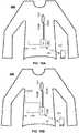
- FIGS 10A, 10Billustrate exemplary wearable devices 400 for determining effect or amount of aging according to an advantageous embodiment of the invention, where said wearable device comprises the arrangement 300 of Figure 9 having at least one of the previous arrangements 200 illustrated in Figures 3-7 with the first and second transmitting loops.
- the loops 103A, 103Care arranged in different locations of the wearable device so that another transmitting loop 103C will be exposed to higher erosion than the first transmitting loop 103A during usage, whereupon the aging can again be detected by comparing the different rates of changing of the properties, such as different rates of changing of resistances of the loops, as can be seen in diagram depicted in Figure 8 ..
- the wearable devicemay comprise plurality of first transmitting loops and/or second transmitting loops with the same functional analogy as described in this document.
- at least one second transmitting loopmay be used for powering the end device.
- the arrangementmay also control data transmission via the second transmitting loop, whereupon the manipulation may also comprise adapting line impedance of the data transmission loop or line based on the (changed) value of the property of the first transmitting loop.
- the line impedance of the data transmission loop or lineis typically 50 ⁇ or 75 ⁇ (Ohm). However, during the use of the wearable device the line impedance may change.
- the data processing unit 104may also perform active impedance matching to the transmission line (so the second transmitting loop used as said transmission line) so to keep the impedance of the line as desired.
- the impedance matchingis advantageously done based on the (changed) value of the property of the first transmitting loop.
- the first and second transmitting loopsmay be physically separate loops or the same transmitting loop.
Landscapes
- Health & Medical Sciences (AREA)
- Life Sciences & Earth Sciences (AREA)
- Engineering & Computer Science (AREA)
- Biomedical Technology (AREA)
- Medical Informatics (AREA)
- Public Health (AREA)
- General Health & Medical Sciences (AREA)
- Physics & Mathematics (AREA)
- Veterinary Medicine (AREA)
- Surgery (AREA)
- Animal Behavior & Ethology (AREA)
- Heart & Thoracic Surgery (AREA)
- Pathology (AREA)
- Biophysics (AREA)
- Molecular Biology (AREA)
- Physiology (AREA)
- Pulmonology (AREA)
- Cardiology (AREA)
- Dentistry (AREA)
- Oral & Maxillofacial Surgery (AREA)
- Business, Economics & Management (AREA)
- General Business, Economics & Management (AREA)
- Epidemiology (AREA)
- Primary Health Care (AREA)
- Nuclear Medicine, Radiotherapy & Molecular Imaging (AREA)
- Radiology & Medical Imaging (AREA)
- General Physics & Mathematics (AREA)
- Measuring And Recording Apparatus For Diagnosis (AREA)
Description
- The invention relates to a device for determining effects of aging of a wearable device or an object integrated into the wearable device, such as a garment. Especially the invention relates to determining effects of aging related to a wearable sensor, object or device. In addition the invention relates to a method of manufacturing the devices.
- Generally known fact is that all devices and especially wearable device wear or ages during using of it. In some cases there is a need for determining a level of aging of the device, such as especially wearable devices, like apparels, garments or clothing, and in particularly sport or activity apparels. In addition it is commonly known that the wearable devices may nowadays comprise plurality of electronic sensor, including e.g. sensors and data processing units, as well as electrical wires or other data communication lines integrated into the wearable devices, especially into the apparels, garments or clothing, for transmitting e.g. measured electrical signals between the sensors, sensors or data processing units or the like.
US20110282164 discloses a sensing device having a plurality of sensors, which are electrically connected to form a loop. The loop has two output ends. There is a loop output value between the two output ends. The loop output value varies when the sensors are subjected to an external force. Each sensor has one induction value. The induction value of each sensor is different from each other. A total induction value of any one or more sensors is different from a total induction value of the other one or more sensors.- In addition
WO2013033238 discloses a wearable therapeutic device having a sensing electrode in a garment to facilitate care of a subject. The garment includes at least one of an inductive element and a capacitive element, and a controller identifies an inductance of the inductive element or a capacitance of the capacitive element, and determines a confidence level of information received from the sensing electrode based on the inductance or the capacitance. The wearable therapeutic device also includes an alarm module coupled with the controller and configured to provide a notification to a subject based on the confidence level. - Furthermore
US8704758B1 discloses a method for enabling contact or touch point location detection to be implemented on a particular garment for example in relation to a human interface input devices for data, control and command entry into computers and other systems. In particularlyUS8704758B1 relates to a method to detect the presence or absence of users touch along a curvilinear element, that can be configured as a simple loop or that may form more complex two dimensional regions. This curvilinear element would be established on a flexible material that could be fabricated into a wearable garment such as a glove, armband or vest. - There are however some disadvantages relating to the known prior art, such as e.g. when the wearable device ages, the aging affects to electrical or other properties of the sensors, sensors and especially to the electrical wires or other data communication lines changes. For example resistance of the electric wire connecting the data processing units and the measuring sensor may change due to aging or e.g. mechanical stress, whereupon it causes error or deviations to the signal, e.g. measured resistance, detected by the data processing units.
- An object of the invention is to alleviate and eliminate the problems relating to the known prior art. Especially the object of the invention is to provide a device for determining effects of aging of an object of a wearable device, such as aging of a signal transmitting lines or wires or the like, aging of the wearable device itself or aging of a portion of the wearable device. The aging should be understood as a time based aging or aging due to mechanical or stress based aging or deterioration, detrition, erosion or abrasion or all of these. An additional object of the invention is to compensate the measured signals by taking into account the effects of the aging.
- The object of the invention can be achieved by the features of independent claims.
- In accordance with aspects of the invention, there is provided a wearable device according to appended claim 1 and a method according to appended claim 9. Preferable features of the invention are defined in the appended dependent claims.
According to an embodiment of the invention a wearable device comprises an object integrated into the wearable device as well as an arrangement for determining effects of aging of an object of a wearable device. The object may be e.g. the wearable device, like garment itself, or any electrical wiring or conductor, such as printed conductor in or on the wearable device, as an example. The arrangement advantageously comprises first and second transmitting loops coupled with the wearable device and connected to a data processing unit. The second transmitting loop may also be coupled with an end device, such as a sensor outputting a measuring signal. In addition the loops have a property with a readable value, where the readable value depends on an aging of the object of a wearable device, whereupon the data processing unit measures the value of the property of the first transmitting loop and thereby determines effects or amount of the aging, as is described in more details elsewhere in this document.
According to an embodiment the first transmitting loop is physically one transmitting loop, whereupon the measurements of the value of the property are made sequentially, so the first measurement is done at the first moment and the second measurement is done at the second moment being later than said first moment. In this embodiment the effects of the aging are determined by comparing the sequentially measured results with each other and thereby determining the aging via the changed measured values. Alternatively or in addition to a baseline or factory value of said property of said loop can be used for determination of aging. In this case it is advantageous to know the baseline or factory value (property) of the loop at a first time, whereupon the read current value can be compared to the baseline or factory value. When the trend or dependency or behaviour of the property of the loop is known in function of time, the effects or amount of aging can be determined based on the comparison of the current value to the baseline or factory value. For example it is known that baseline or factory value for resistance of a certain loop is Ω1 at first, but during time i.e. due to aging the resistance of said loop for example increases linearly (or other manner), whereupon the degree of the aging can be estimated and determined based on current reading and comparing to known behaviour or trend of that component property. In practice the data processing unit may be configured to determine the effects or amount of aging by comparing the currently read value of said property at a second time to said baseline or factory value.
As an example, resistance of a printed conductor will increase in time, whereupon the aging can be determined via determining changes in resistance in time. Thus according to an example at least portion of the first and/or second transmitting loops is advantageously printed conductive conductor.
Also other electrical properties of the loop can be detected, such as conductance, capacitance or inductance. In addition the property may also be another property, such as an optical property, like intensity, polarization or wavelength. When the behaviour or changes of the property in time or under mechanical pressure or under loading is known, the effect or amount of aging can be determined. Therefore the loops may be e.g. electrically or optically implemented loops, whereupon they are coupled with the data processing unit advantageously either galvanically and/or optically, and the property is electrical or optical property.
The determined effect or amount of the aging can be used to provide notification of either aging level of the object or notification, such as an indication via a LED light or sound device that the object or the wearable device is over aged based on said determined effect or amount of aging. According to an embodiment the data processing unit may send information related to the determined effect or amount of the aging further e.g. to an outer device, such as a smart phone or the like, which then can provide notification or even further process said data and provide an indication about the aging level of the object or that the object or the wearable device is over aged. Alternative, or in addition, the determined effect or amount of the aging (or even the measured difference in the values of the property) can be used to manipulate, such as compensate or correct, the measured signals read via the second transmitting loop. The signal manipulation is advantageously based on the value of the property of the first transmitting loop. - According to an example the second transmitting loop may be a loop or conductor, such as a printed conductor, used for powering an end device, like a LED light source, heating element, antenna, intelligent component or the like, whereupon the determined effect or amount of the aging of the first transmitting loop can be used to manipulate the fed power to the second transmitting loop and again to the end device, such as adjusting the electric current or voltage and thereby compensating possible changes in conductivity of the second transmitting loop.
The wearable device is advantageously a garment or a structure portion of the garment, such as a strap or belt, heart rate sensor strap, shirt, belt, sleeve, back or front portion of a shirt, leg, pocket, brand label, elastic portion of the garment, hat, bra, underwear, jacket, trousers, swimming suit, band, shoe, sock and/or glove, for example. The sensor is advantageously a sensor for detecting biosignals, heart rate, respiration rate, posture of the user, temperature, humidity, conductivity, and/or acceleration, for example.
The present invention offers advantages over the known prior art, such as the possibility to determine the degree of the aging of the object, such as aging of the printed loops integrated into the garment or even the garment as such. In addition according to the invention the effects or amount of the aging can be taken into account in order to correct e.g. measuring signals, because the aging causes changes into the property of the measuring lines, such as to the printed conductors, which is especially important when measuring very weak signals or where the sensor as such determines e.g. changes in resistance, whereupon the resistance changes in the measuring loop due to aging are highly important. - Next the invention will be described in greater detail with reference to exemplary embodiments in accordance with the accompanying drawings, in which:
- Figures 1-2
- illustrate principles of exemplary prior art devices for measuring signals,
- Figure 3-7
- illustrate exemplary loop constructions for determining effect or amount of aging,
- Figure 8
- illustrate exemplary diagram of changing properties of two different loops in function of time,
- Figure 9
- illustrates an exemplary arrangement for determining effect or amount of aging, and
- Figures 10A, 10B
- illustrate exemplary wearable devices for determining effect or amount of aging.
Figures 1-2 illustrate principles of exemplaryprior art arrangements 100 for measuring signals. Thesearrangements 100 may be integrated into the garment for measuring biosignals via asensor 101, such as voltage induced by heart rate (Figure 1 ) or e.g. body temperature via thermocouple illustrated inFigure 2 . Theconductors 102 may be implemented e.g. by a copper conductors, which are however uncomfortable. Nowadays printed conductors are used because they are comfortable and are very durable. However the problems related to the printed conductors include e.g. the changes in resistances in time and due to mechanical stress and loads. The changes in resistances in theconductors 102 causes easily interferences to the measuring signals, especially when the measuring signals are weak or base on measuring resistance or other property, to which the aging also affects in theconductors 102.Figure 3-7 illustrate exemplary loop constructions for determining effect or amount of aging.- In
Figure 3 the loop construction or thearrangement 200 comprises actually onephysical transmitting loop 103, which is however construed to function functionally as said first transmitting loop so that the transmittingloop 103 functions as thefirst transmitting loop 103A at the first moment and as thesecond transmitting loop 103B at the second moment being late that said first moment. In this embodiment the effects or amount of aging are determined by comparing the sequentially measured results with each other and thereby determining the aging via the changed measured values. Thus the measurement of aging is not continuous, but must be made sequentially. For example change of resistance or other value of the loop is depend on time, whereupon the aging can be determined based on the change of resistance or other value. - In
Figure 4 the loop construction or thearrangement 200 comprises the transmittingloop 103, which corresponds the case described inFigure 3 , but the transmitting loop is additionally coupled with asensor 101. Thearrangement 200 inFigure 4 is construed to function as said first andsecond transmitting loops loop 103 functions as thefirst transmitting loop 103A at the first moment (reference loop) and as thesecond transmitting loop 103B (measuring loop) at the second moment measuring the reading of thesensor 101. In this embodiment the effect of aging is taken into account by comparing sequentially measured results of the transmittingloop 103A, when functioning as said reference loop and not as said measuring loop. Thus the measurement of aging is not continuous. Thereby the effects or amount of aging can also be taking into account in the measured signal of the sensor. - In
Figure 5 the arrangement comprises thesecond transmitting loop 103B coupled with thesensors 101, as well thefirst transmitting loop 103A coupled advantageously with the wearable device and functioning as a reference loop. The term loop is used even if the measurement can be done by one wire. There the signal measurement by thesecond transmitting loop 103B and the aging determination via thefirst transmitting loop 103A can be done simultaneously. Also the effect or amount of aging can be taken into account at every turn when measuring either signal. Figure 6 illustrates anarrangement 200, where thesecond transmitting loop 103B is again coupled with thesensor 101. Thefirst transmitting loop 103A functioning as a reference loop may be either a separate loop of thesecond transmitting loop 103B and thus corresponding the embodiment ofFigure 5 . Alternatively onebranch 103A1 of thefirst transmitting loop 103B can be implemented by thefirst branch 103A1 of thesecond transmitting loop 103B and the second branch (as a return channel) 103A2 of the first transmitting loop can be implemented by a separate branch (dashed line), whereupon the signal measurement by thesecond transmitting loop 103B and the aging determination via thefirst transmitting loop Figure 5 .Figure 7 illustrates anarrangement 300, where the first 103A and second (or third) 103C transmitting loops are separate transmitting loops. In addition the arrangement may additionally comprise an end device orsensor 101 for detecting biosignals, which has own loop for transferring measuring signal. According to an example the property to be measured and depending on the aging of the object of a wearable device is amutual property 601 of saidloops 103Amutual property 601, such as capacitance or resistance between said loops, changes. Typically the wearable device and object absorbs sweat including e.g. salts, which will be trapped into the porosity material structure of the wearable device and object and thus changes electrical properties between said loops, such as capacitance or resistance. When the mutual property 601 (so e.g. electrical property) is changed over a predetermined threshold value, it can be construed that the object of the wearable device is then aged and should be e.g. disposed of or changed. Themutual property 601 may be understood also according to an embodiment as a short circuit in an electrical way at the situation where the object of the wearable device is aged.- According to an example the first 103A and second 103C transmitting loops are selected so that their properties (so readable values) depend on aging in different way. For example the electrical property of the
first loop 103A material (e.g. carbon ink) changes more rapidly during aging than the electrical property of the second loop material (e.g. silver ink), whereupon the trend or amount of difference between these two values implies the aging of the object of the wearable device. Also or alternatively the physical structure of the first andsecond loops first loop 103A changes more rapidly during aging than the electrical property of the second loop structure (e.g. thick and wide straight printed loop), whereupon the trend or amount of difference between these two values implies the aging of the object of the wearable device. - In addition it is to be noted that the arrangement may also comprise a reference component, such as a
resistance 201 corresponding the original resistance (or other property) of thesensor 101, whereupon the compensation for the measured signal of 101 can be compensated by using the value of thecomponent 201, to which said aging does not influence as it does to the component orsensor 101. Figure 8 illustrate exemplary diagram 800 of changing properties of twodifferent loops property 701 of the first loop changes more rapidly during aging than theproperty 702 of the second loop. For example at the first time moment t1 the difference of the properties between the first and second loops has a certainfirst value 703, whereas at the second moment t2 later than said first moment the difference has a certainsecond value 704 being greater than said first value at the first moment. Therefore the trend or amount ofdifferences Figure 9 illustrates anexemplary arrangement 300 for determining effect or amount of aging according to an advantageous embodiment of the invention, where thearrangement 300 comprises any of previous arrangement illustrated inFigures 3-7 with the first and second transmitting loops. Thearrangement 300 advantageously comprises adata processing unit 104, wherein the first and second transmitting loops are coupled with said data processing unit. The coupling may be made galvanically and/or optically, depending on the type of the loop and the property to be read (electrical or optical property).- The data processing unit may be any known data processing unit, which is configured to measure the value of said property of the first and
second transmitting loops indication device 105 of either aging level of the object, where it is integrated, or notification (such as LED light or sound or the like 105) that the object or the wearable device is over aged based on said determined effect or amount of aging. Alternatively, or in addition to, thedata processing unit 104 may be configured to communicate 301 the determined effect or amount of the aging further e.g. to anouter device 302, such as a smart phone or the like, which then can provide notification or even further process said data and provide an indication about the aging level of the object or that the object or the wearable device is over aged. - Again it is to be noted that the
arrangement first transmitting loops 103A and/or second transmittingloops 103B. In addition thearrangement end device 303, such as a LED light source, whereupon at least onesecond transmitting loop 103B (left inFigure 9 ) may be used for powering it. - Furthermore according to an embodiment the
data processing unit 104 is advantageously configured to manipulate, such as compensate or correct, the measured signals read via thesecond transmitting loop 103B based on the value of the property of the first transmitting loop, when this is possible so when the signal reading from the sensor is read (e.g. arrangements inFigures 5, 6 ), or to manipulate the fed power to thesecond transmitting loop 103B (left inFigure 9 ) and again to theend device 303. Figures 10A, 10B illustrate exemplarywearable devices 400 for determining effect or amount of aging according to an advantageous embodiment of the invention, where said wearable device comprises thearrangement 300 ofFigure 9 having at least one of theprevious arrangements 200 illustrated inFigures 3-7 with the first and second transmitting loops.- In
Figure 10B theloops loop 103C will be exposed to higher erosion than thefirst transmitting loop 103A during usage, whereupon the aging can again be detected by comparing the different rates of changing of the properties, such as different rates of changing of resistances of the loops, as can be seen in diagram depicted inFigure 8 .. - The invention has been explained above with reference to the aforementioned embodiments, and several advantages of the invention have been demonstrated. It is to be noted that even if the term loop is used, the measurements can also be done by one conductor. The features recited in dependent claims are mutually freely combinable unless otherwise explicitly stated.
- In addition it is to be noted that the wearable device may comprise plurality of first transmitting loops and/or second transmitting loops with the same functional analogy as described in this document. Furthermore it is to be noted that at least one second transmitting loop may be used for powering the end device. Still on addition the arrangement may also control data transmission via the second transmitting loop, whereupon the manipulation may also comprise adapting line impedance of the data transmission loop or line based on the (changed) value of the property of the first transmitting loop. As an example the line impedance of the data transmission loop or line is typically 50 Ω or 75Ω (Ohm). However, during the use of the wearable device the line impedance may change. Thus, according to the invention the
data processing unit 104 may also perform active impedance matching to the transmission line (so the second transmitting loop used as said transmission line) so to keep the impedance of the line as desired. The impedance matching is advantageously done based on the (changed) value of the property of the first transmitting loop. Again it is to be noted that the first and second transmitting loops may be physically separate loops or the same transmitting loop.
Claims (9)
- A wearable device (400) comprising an arrangement (200, 300) for determining amount of aging of the wearable device:
wherein the arrangement comprises:- a data processing unit (104),- a sensor (101) having a property, and- a loop (103) coupled with the wearable device and sensor, which loop is an electrically implemented loop and has an electrical property which can be measured from the loop,- the loop (103) is configured to function as a reference loop (103A) at a first moment measuring the electrical property of the loop (103) and as a measuring loop (103B) at a second moment measuring the reading of the sensor (101),- the electrical property with a readable value of the loop (103) and the property of the sensor (101) vary different ways in time and thereby the readable value of the loop depends on the amount of aging of the loop and the readable value of the sensor depends on the amount of aging of the loop and sensor and thereby both values depend on aging of the wearable device to which the loop and sensor are coupled with, and- wherein the loop (103) is coupled with the data processing unit (104) electrically, so that the data processing unit (104) is configured to measure electrical property values of the reference loop (103A) and measuring loop (103B),wherein the data processing unit (104) is configured to determine the amount of aging based on a different amount of change in measured values of the electrical property of the reference loop (103A) and measuring loop (103B), wherein the difference of the measured values is compared to another predetermined measured difference value of the electrical property of the reference loop and measuring loop, where a trend or dependency or behaviour of the electrical property of the measured values is known in function of time or under mechanical deterioration, detrition, erosion or abrasion. - A wearable device of any of previous claims, wherein a baseline or factory value of the property of the loop (103) is known at a first time and the data processing unit is configured to determine the effects or amount of aging by comparing the currently read value of the electrical property at a second time to the baseline or factory value, and where the trend of the property as a function of time is also known.
- A wearable device of any of previous claims, wherein whereupon the aging of the wearable device causes changes to the readable value of the electrical property of the loop (103, 103A, 103B).
- A wearable device of any of previous claims, wherein the data processing unit (104) is configured to manipulate, such as compensate or correct, the measured signals read via the measuring loop (103B) based on the value of the property of the reference loop (103A), or to manipulate power to the measuring loop coupled with an end device (303) or to perform active impedance matching to the measuring loop (103B) functioning as a transmission line so to keep the impedance of the line as desired based on the value of the property of the reference loop (103A).
- A wearable device of any of previous claims, wherein the wearable device (400) is a garment or a structure portion of the garment, such as a strap or belt, heart rate sensor strap, shirt, belt, sleeve, back or front portion of a shirt, leg, pocket, brand label, elastic portion of the garment, hat, bra, underwear, jacket, trousers, swimming suit, band, shoe, sock or glove.
- A wearable device of any of previous claims, wherein the sensor (101) is configured to detect biosignals, heart rate, respiration rate, posture of the user, temperature, humidity, conductivity, or acceleration.
- A wearable device of any of previous claims, wherein the electrical property of the loop is resistance, conductance, capacitance or inductance.
- A wearable device of any of previous claims, wherein the wearable device is configured to provide a notification (105) of either an aging level of an object integrated into the wearable device or a notification that the object or the wearable device is over aged based on the determined effect or amount of aging, whereupon the notification is provided to an indication device of the wearable device or to an outer device (302).
- A method for manufacturing a wearable device (400) of any of previous claims comprising an arrangement (200, 300) for determining effects of aging of the wearable device
wherein the method comprises steps:- providing the wearable device with a data processing unit (104),- providing the wearable device with a sensor (101) having a property,- coupling a loop (103) with the wearable device and sensor, where the loop is an electrically implemented loop and has an electrical property which is to be measured from the loop,- providing the loop (103) to function as a reference loop (103A) at a first moment measuring the electrical property of the loop (103) and as a measuring loop (103B) at a second moment measuring the reading of the sensor (101),- the electrical property with a readable value of the loop (103) and the property of the sensor (101) vary different ways in time and thereby the readable value of the loop depends on amount of aging of the loop and the readable value of the sensor depends on the amount of aging of the loop and sensor and thereby both values depend on aging of the wearable device to which the loop and sensor are coupled with, and- coupling the loop (103) with the data processing unit (104) electrically so that the data processing unit measures electrical property values of the reference loop (103A) and measuring loop (103B), the method further comprising a step wherein:- configuring the data processing unit (104) to determine the amount of aging based on a different amount of change in the measured values of the electrical property of the reference loop (103A) and measuring loop (10B), wherein the difference of the measured values is compared to another predetermined measured difference value of the electrical property of the reference loop and measurement loop, where a trend or dependency or behaviour of the electrical property of the measured values is known in function of time or under mechanical deterioration, detrition, erosion or abrasion.
Applications Claiming Priority (1)
| Application Number | Priority Date | Filing Date | Title |
|---|---|---|---|
| FI20146057 | 2014-12-03 |
Publications (2)
| Publication Number | Publication Date |
|---|---|
| EP3028587A1 EP3028587A1 (en) | 2016-06-08 |
| EP3028587B1true EP3028587B1 (en) | 2020-03-11 |
Family
ID=54782492
Family Applications (1)
| Application Number | Title | Priority Date | Filing Date |
|---|---|---|---|
| EP15197241.1AActiveEP3028587B1 (en) | 2014-12-03 | 2015-12-01 | Device for determining effects of aging of a wearable device |
Country Status (2)
| Country | Link |
|---|---|
| US (2) | US11291409B2 (en) |
| EP (1) | EP3028587B1 (en) |
Families Citing this family (10)
| Publication number | Priority date | Publication date | Assignee | Title |
|---|---|---|---|---|
| US10892588B2 (en)* | 2016-12-01 | 2021-01-12 | Dupont Electronics, Inc. | Electrical connections for wearables and other articles |
| EP3366211A1 (en)* | 2017-02-27 | 2018-08-29 | Koninklijke Philips N.V. | Wearable device |
| CN108538799B (en) | 2017-03-02 | 2024-02-27 | 弗莱克斯有限公司 | Interconnect component and interconnect assembly |
| CN107280652A (en)* | 2017-07-21 | 2017-10-24 | 镇安县秦绿食品有限公司 | A kind of monitoring swimmer's safety information system in real time |
| CN108926430A (en)* | 2018-09-26 | 2018-12-04 | 深圳市安全家科技有限公司 | A kind of intelligent paper diaper |
| US11668686B1 (en) | 2019-06-17 | 2023-06-06 | Flex Ltd. | Batteryless architecture for color detection in smart labels |
| GB2597726B (en)* | 2020-07-31 | 2023-07-12 | Prevayl Innovations Ltd | System comprising an electronics module |
| WO2022172033A1 (en)* | 2021-02-15 | 2022-08-18 | Prevayl Innovations Limited | Method, wearable article and assembly |
| GB2603794A (en)* | 2021-02-15 | 2022-08-17 | Prevayl Innovations Ltd | Method, wearable article and assembly |
| CN118177822B (en)* | 2024-03-27 | 2024-11-19 | 宁波理得医疗科技有限公司 | Signal processing method and system based on wearable electrocardiograph acquisition |
Citations (1)
| Publication number | Priority date | Publication date | Assignee | Title |
|---|---|---|---|---|
| US8704758B1 (en)* | 2008-11-17 | 2014-04-22 | Iron Will Innovations Canada Inc. | Resistive loop excitation and readout for touch point detection and generation of corresponding control signals |
Family Cites Families (123)
| Publication number | Priority date | Publication date | Assignee | Title |
|---|---|---|---|---|
| US3479565A (en) | 1967-09-06 | 1969-11-18 | Southern Weaving Co | Woven circuit device |
| US3631298A (en) | 1969-10-24 | 1971-12-28 | Bunker Ramo | Woven interconnection structure |
| US3954100A (en) | 1974-12-10 | 1976-05-04 | International Defense Consultant Services, Inc. | Flexible sensor pad for non-attached monitoring EKG signals of human subjects |
| CH662717A5 (en) | 1983-04-12 | 1987-10-30 | Jago Pharma Ag | Electrode with a lead for detecting electric signals on a living body, in particular for detecting electric signals to be related to the heart |
| US4729377A (en) | 1983-06-01 | 1988-03-08 | Bio-Stimu Trend Corporation | Garment apparatus for delivering or receiving electric impulses |
| US4763660A (en) | 1985-12-10 | 1988-08-16 | Cherne Industries, Inc. | Flexible and disposable electrode belt device |
| US5341806A (en) | 1991-04-18 | 1994-08-30 | Physio-Control Corporation | Multiple electrode strip |
| FI88223C (en) | 1991-05-22 | 1993-04-13 | Polar Electro Oy | Telemetric transmitter unit |
| US5450845A (en) | 1993-01-11 | 1995-09-19 | Axelgaard; Jens | Medical electrode system |
| EP0692774B1 (en) | 1994-06-13 | 2000-03-01 | Paxar Corporation | Fabric security label |
| US5624736A (en) | 1995-05-12 | 1997-04-29 | Milliken Research Corporation | Patterned conductive textiles |
| US5868671A (en) | 1997-01-28 | 1999-02-09 | Hewlett-Packard Company | Multiple ECG electrode strip |
| DE69841846D1 (en)* | 1997-03-17 | 2010-09-30 | Adidas Ag | INFORMATION RECONDITIONING SYSTEM FOR PHYSIOLOGICAL SIGNALS |
| US6368990B1 (en) | 1997-08-04 | 2002-04-09 | Bba Nonwovens Sweden Ab | Fabrics formed of hollow filaments and fibers and methods of making the same |
| US6400975B1 (en) | 1997-08-14 | 2002-06-04 | Mcfee Robin B. | Apparatus and method for consistent patient-specific electrode positioning for EKG testing and delivery of electrical energy to the heart |
| KR20010024222A (en) | 1997-09-22 | 2001-03-26 | 베리 로센베르그 | Full-Fashioned Weaving Process for Production of a Woven Garment with Intelligence Capability |
| US6381482B1 (en) | 1998-05-13 | 2002-04-30 | Georgia Tech Research Corp. | Fabric or garment with integrated flexible information infrastructure |
| US6210771B1 (en) | 1997-09-24 | 2001-04-03 | Massachusetts Institute Of Technology | Electrically active textiles and articles made therefrom |
| US6080690A (en) | 1998-04-29 | 2000-06-27 | Motorola, Inc. | Textile fabric with integrated sensing device and clothing fabricated thereof |
| SE518130C2 (en) | 1998-10-05 | 2002-08-27 | Sca Hygiene Prod Ab | Absorbent articles with thermoplastic fibers in the liquid transfer layer |
| FI107776B (en) | 1998-06-22 | 2001-10-15 | Polar Electro Oy | shield |
| US6970731B1 (en) | 1998-09-21 | 2005-11-29 | Georgia Tech Research Corp. | Fabric-based sensor for monitoring vital signs |
| WO2000044411A1 (en) | 1999-01-27 | 2000-08-03 | Kimberly-Clark Worldwide, Inc. | Hollow polymer fiber nonwoven web material |
| US6373034B1 (en) | 1999-04-22 | 2002-04-16 | Malden Mills Industries, Inc. | Electric heating/warming fabric articles |
| WO2001002052A2 (en) | 1999-07-01 | 2001-01-11 | N.V. Bekaert S.A. | Garment comprising electrode |
| MXPA02000169A (en) | 1999-07-06 | 2002-07-02 | Georgia Tech Res Inst | Fabric or garment for monitoring vital signs of infants. |
| EP1095612A1 (en) | 1999-10-29 | 2001-05-02 | Arif Dr. Naqvi | Portable ECG apparatus and method |
| US20030022581A1 (en) | 1999-12-29 | 2003-01-30 | Fu-Jya Daniel Tsai | Biodegradable thermoplastic nonwoven webs for fluid management |
| RU2002120286A (en) | 1999-12-29 | 2004-01-10 | Кимберли-Кларк Ворлдвайд, Инк. (Us) | BIOLOGICALLY DEGRADABLE NONWOVEN MATERIALS FOR THE DISTRIBUTION OF LIQUID |
| EP2324760B1 (en) | 2000-04-17 | 2019-07-24 | Adidas AG | System for ambulatory monitoring of physiological signs |
| CA2425224A1 (en) | 2000-10-10 | 2002-04-18 | Alan Remy Magill | Health monitoring |
| ATE494763T1 (en)* | 2000-10-16 | 2011-01-15 | Foster Miller Inc | METHOD FOR PRODUCING A FABRIC ARTICLE WITH ELECTRONIC CIRCUIT AND FABRIC ARTICLE |
| FI119716B (en) | 2000-10-18 | 2009-02-27 | Polar Electro Oy | Electrode construction and pulse measurement device |
| US20020124295A1 (en) | 2000-10-30 | 2002-09-12 | Loel Fenwick | Clothing apparatus, carrier for a biophysical sensor, and patient alarm system |
| FI110915B (en) | 2001-02-19 | 2003-04-30 | Polar Electro Oy | Sensor placed on the skin |
| DE10119283A1 (en)* | 2001-04-20 | 2002-10-24 | Philips Corp Intellectual Pty | System for wireless transmission of electric power, item of clothing, a system of clothing items and method for transmission of signals and/or electric power |
| US7118639B2 (en) | 2001-05-31 | 2006-10-10 | Kimberly-Clark Worldwide, Inc. | Structured material having apertures and method of producing the same |
| WO2003010561A2 (en) | 2001-07-25 | 2003-02-06 | Argose, Inc. | Optical coupler for measuring tissue fluorescence |
| US6755795B2 (en)* | 2001-10-26 | 2004-06-29 | Koninklijke Philips Electronics N.V. | Selectively applied wearable medical sensors |
| US6941775B2 (en) | 2002-04-05 | 2005-09-13 | Electronic Textile, Inc. | Tubular knit fabric and system |
| US6731529B2 (en)* | 2002-06-04 | 2004-05-04 | Infineon Technologies Aktiengesellschaft | Variable capacitances for memory cells within a cell group |
| US20070100666A1 (en)* | 2002-08-22 | 2007-05-03 | Stivoric John M | Devices and systems for contextual and physiological-based detection, monitoring, reporting, entertainment, and control of other devices |
| GB0311320D0 (en) | 2003-05-19 | 2003-06-25 | Univ Manchester | Knitted transducer devices |
| EP1504739B1 (en) | 2003-08-07 | 2013-01-30 | The Procter & Gamble Company | Latex bonded acquisition layer for absorbent articles |
| DE10338029B4 (en) | 2003-08-19 | 2010-04-08 | Infineon Technologies Ag | Fabric and garment made from this fabric |
| WO2005032447A2 (en) | 2003-08-22 | 2005-04-14 | Foster-Miller, Inc. | Physiological monitoring garment |
| ITFI20030308A1 (en) | 2003-12-03 | 2005-06-04 | Milior S P A | KNITTED FABRIC FOR MONITORING OF VITAL SIGNALS. |
| US8668653B2 (en)* | 2004-03-24 | 2014-03-11 | Nihon Kohden Corporation | Biological information measuring garment having sensor, biological information measuring system and equipment, and control method of equipment |
| US9026200B2 (en)* | 2004-03-24 | 2015-05-05 | Nihon Kohden Corporation | Garment for bioinformation measurement having electrode, bioinformation measurement system and bioinformation measurement device, and device control method |
| US7173437B2 (en) | 2004-06-10 | 2007-02-06 | Quantum Applied Science And Research, Inc. | Garment incorporating embedded physiological sensors |
| US7206630B1 (en) | 2004-06-29 | 2007-04-17 | Cleveland Medical Devices, Inc | Electrode patch and wireless physiological measurement system and method |
| DE102004038636A1 (en) | 2004-07-24 | 2006-02-16 | medi Bayreuth Weihermüller & Voigtmann GmbH & Co. KG | Electrically biaxially conductive fabric |
| ES2338062T3 (en) | 2004-09-06 | 2010-05-03 | Upm Raflatac Oy | A LABEL. |
| WO2006029105A2 (en) | 2004-09-07 | 2006-03-16 | Meadwestvaco Corporation | Apparatus for and method of providing rfid tags |
| US20080039687A1 (en)* | 2004-10-15 | 2008-02-14 | Hatsuo Shimizu | Radio Intra-Subject Information Acquiring System |
| DE102004058731A1 (en) | 2004-12-06 | 2006-06-08 | Infineon Technologies Ag | Measurement system for control keys in smart fabrics, for garments with wearable electronics e.g. music systems, has an ohmmeter to measure the key resistance to determine if it is pressed deliberately or accidentally |
| US7191803B2 (en) | 2004-12-13 | 2007-03-20 | Woven Electronics Corporation | Elastic fabric with sinusoidally disposed wires |
| US7212127B2 (en) | 2004-12-20 | 2007-05-01 | Avery Dennison Corp. | RFID tag and label |
| US8224418B2 (en) | 2004-12-21 | 2012-07-17 | Polar Electro Oy | Integral heart rate monitoring garment |
| FI20045503A7 (en) | 2004-12-28 | 2006-06-29 | Polar Electro Oy | Sensor system, accessory and heart rate monitor |
| US7277021B2 (en) | 2005-01-11 | 2007-10-02 | Wisconsin Alumni Research Foundation | Device and method for alerting a runner when a new pair of running shoes is needed |
| WO2006094152A2 (en) | 2005-03-01 | 2006-09-08 | National Label Company | Radio frequency identification and method of labeling |
| WO2006095279A1 (en) | 2005-03-08 | 2006-09-14 | Philips Intellectual Property & Standards Gmbh | A garment comprising at least one dry electrode |
| US7308294B2 (en) | 2005-03-16 | 2007-12-11 | Textronics Inc. | Textile-based electrode system |
| US20060224072A1 (en) | 2005-03-31 | 2006-10-05 | Cardiovu, Inc. | Disposable extended wear heart monitor patch |
| US20060267790A1 (en) | 2005-05-24 | 2006-11-30 | Dräger Safety AG & Co. KGaA | Modular system for electronic assembly units worn close to the body |
| CN101184876A (en) | 2005-05-31 | 2008-05-21 | 皇家飞利浦电子股份有限公司 | Full fabric electrode layout allowing passive and active matrix addressing |
| FI20050593A0 (en) | 2005-06-03 | 2005-06-03 | Clothing Plus Oy | Procedure and arrangement for protecting sensitive components with textile and product containing the arrangement |
| KR100734986B1 (en) | 2005-09-23 | 2007-07-06 | 한국전자통신연구원 | Bio signal garment |
| US20070089800A1 (en) | 2005-10-24 | 2007-04-26 | Sensatex, Inc. | Fabrics and Garments with Information Infrastructure |
| FI119456B (en) | 2006-01-31 | 2008-11-14 | Polar Electro Oy | The connector mechanism |
| US7712373B2 (en) | 2006-03-03 | 2010-05-11 | Nagle H Troy | Sensor device for real-time monitoring or relative movement using capacitive fabric sensors |
| US7790640B2 (en) | 2006-03-23 | 2010-09-07 | Kimberly-Clark Worldwide, Inc. | Absorbent articles having biodegradable nonwoven webs |
| FI120482B (en) | 2006-06-08 | 2009-11-13 | Suunto Oy | Anturointijärjestely |
| JP4829043B2 (en) | 2006-08-29 | 2011-11-30 | セイコーインスツル株式会社 | Biological information detector |
| WO2008039082A2 (en) | 2006-09-25 | 2008-04-03 | Zephyr Technology Limited | Bio-mechanical sensor system |
| CN200966186Y (en) | 2006-09-30 | 2007-10-24 | 比亚迪股份有限公司 | A flexible printed circuit product |
| FI20065787A7 (en) | 2006-12-11 | 2008-06-12 | Corusfit Oy | System, measuring device and method for measuring a person's electrocardiogram |
| US8527028B2 (en) | 2007-05-16 | 2013-09-03 | Medicomp, Inc. | Harness with sensors |
| US8140154B2 (en) | 2007-06-13 | 2012-03-20 | Zoll Medical Corporation | Wearable medical treatment device |
| CN201114998Y (en) | 2007-09-27 | 2008-09-10 | 惠州市蓝微电子有限公司 | A soft and hard combination board structure |
| FI20075798A0 (en) | 2007-11-12 | 2007-11-12 | Polar Electro Oy | The electrode structure |
| TWI370714B (en) | 2008-01-09 | 2012-08-11 | Ind Tech Res Inst | Circuit structure and menufacturing method thereof |
| US8099254B2 (en)* | 2008-01-11 | 2012-01-17 | Minnesota Wire and Cable | Elastomeric conductor and shield fault detection |
| US7832133B2 (en) | 2008-01-28 | 2010-11-16 | Avery Dennison Corporation | Labeling method, web of labels and label array |
| KR100982532B1 (en) | 2008-02-26 | 2010-09-16 | 한국생산기술연구원 | Digital garment using knitting technology and manufacturing method thereof |
| DE102008051536A1 (en)* | 2008-10-14 | 2010-04-15 | Cairos Technologies Ag | Garment for monitoring physiological properties |
| KR101551881B1 (en)* | 2008-10-30 | 2015-09-21 | 삼성전자주식회사 | Apparatus and method of integratedly processing a plurality of bio signals |
| US9462978B2 (en)* | 2009-01-24 | 2016-10-11 | Ming Young Biomedical Corp. | Sensing device |
| US20110160601A1 (en) | 2009-12-30 | 2011-06-30 | Yang Wang | Wire Free Self-Contained Single or Multi-Lead Ambulatory ECG Recording and Analyzing Device, System and Method Thereof |
| US8874180B2 (en) | 2010-02-28 | 2014-10-28 | Covidien Lp | Ambient electromagnetic energy harvesting with wireless sensors |
| CN102315574A (en) | 2010-07-09 | 2012-01-11 | 鸿富锦精密工业(深圳)有限公司 | Connecting component |
| US8904214B2 (en)* | 2010-07-09 | 2014-12-02 | Zoll Medical Corporation | System and method for conserving power in a medical device |
| FI123363B (en)* | 2011-01-31 | 2013-03-15 | Clothing Plus Holding Oy | Substrate of textile for measuring a physical quantity |
| AU2012220340A1 (en)* | 2011-02-22 | 2013-08-22 | Joelmar Pty Ltd | Survival and location enhancement garment and headgear |
| US20130281795A1 (en) | 2012-04-18 | 2013-10-24 | The Board Of Trustees Of The University Of Arkansas | Wearable remote electrophysiological monitoring system |
| BR112013032419A2 (en) | 2011-06-20 | 2017-01-17 | Healthwatch Ltd | Independent, non-interfering usable health monitoring and alert system |
| CN103764222B (en)* | 2011-09-01 | 2016-02-10 | 佐尔医药公司 | Wearable monitoring and treatment equipment |
| WO2013075270A1 (en) | 2011-11-25 | 2013-05-30 | Yang Chang-Ming | Object, method, and system for detecting heartbeat or whether or not electrodes are in proper contact |
| US20130160183A1 (en) | 2011-12-23 | 2013-06-27 | Akseli Reho | Textile arrangement and method for manufacturing |
| US9737261B2 (en) | 2012-04-13 | 2017-08-22 | Adidas Ag | Wearable athletic activity monitoring systems |
| GB2503716A (en) | 2012-07-05 | 2014-01-08 | Sml Europ Ltd | Composite label comprising two detachable portions where one portion comprises an identification device |
| JP2014031157A (en) | 2012-07-10 | 2014-02-20 | Koito Mfg Co Ltd | Vehicular lamp |
| US8945328B2 (en)* | 2012-09-11 | 2015-02-03 | L.I.F.E. Corporation S.A. | Methods of making garments having stretchable and conductive ink |
| EP2895050B8 (en)* | 2012-09-11 | 2018-12-19 | L.I.F.E. Corporation S.A. | Wearable communication platform |
| US8948839B1 (en)* | 2013-08-06 | 2015-02-03 | L.I.F.E. Corporation S.A. | Compression garments having stretchable and conductive ink |
| US9817440B2 (en)* | 2012-09-11 | 2017-11-14 | L.I.F.E. Corporation S.A. | Garments having stretchable and conductive ink |
| US10462898B2 (en)* | 2012-09-11 | 2019-10-29 | L.I.F.E. Corporation S.A. | Physiological monitoring garments |
| DE102012218068B4 (en) | 2012-10-02 | 2025-10-09 | Adidas Ag | ITEM OF GARMENT |
| US10143405B2 (en)* | 2012-11-14 | 2018-12-04 | MAD Apparel, Inc. | Wearable performance monitoring, analysis, and feedback systems and methods |
| US20140180036A1 (en)* | 2012-12-21 | 2014-06-26 | The Board Of Regents For Oklahoma State University | Device and method for predicting and preventing obstructive sleep apnea (osa) episodes |
| US20140275883A1 (en) | 2013-03-14 | 2014-09-18 | Covidien Lp | Wireless sensors |
| FI124902B (en) | 2013-07-18 | 2015-03-13 | Framgo Oy | Apparatus for measuring electrophysiological signals and a manufacturing method for making the apparatus |
| SG11201607189VA (en) | 2014-03-09 | 2016-09-29 | Healthwatch Ltd | Elastic conductive stripe and methods of utilizing thereof |
| EP2928271A1 (en)* | 2014-04-04 | 2015-10-07 | Clothing Plus MBU Oy | Stretchable device for transmitting signal |
| US9474154B2 (en) | 2014-07-18 | 2016-10-18 | Starkey Laboratories, Inc. | Reflow solderable flexible circuit board — to — flexible circuit board connector reinforcement |
| WO2016023027A1 (en)* | 2014-08-08 | 2016-02-11 | Orn, Inc. | Garment including integrated sensor components and feedback components |
| FI20145747A7 (en)* | 2014-08-28 | 2016-02-29 | Clothing Plus Mbu Oy | A module installable with a garment and the garment |
| US10660382B2 (en)* | 2015-02-27 | 2020-05-26 | Honeywell Safety Products Usa, Inc. | Apparatus, systems and methods for optimizing and masking compression in a biosensing garment |
| CN108139197B (en)* | 2015-09-01 | 2020-11-17 | 霍尼韦尔安全产品美国股份有限公司 | System and method for monitoring respiration in biosensing garments |
| US20170082418A1 (en)* | 2015-09-21 | 2017-03-23 | Figur8, Inc. | Electronic fabric for shape measurement |
| US20180010902A1 (en)* | 2015-09-21 | 2018-01-11 | Figur8, Inc. | Fabric with stretchable sensors for shape measurement |
| US10037672B1 (en)* | 2017-03-29 | 2018-07-31 | International Business Machines Corporation | Smart garments that identify user changes |
- 2015
- 2015-12-01EPEP15197241.1Apatent/EP3028587B1/enactiveActive
- 2015-12-02USUS14/956,458patent/US11291409B2/enactiveActive
- 2022
- 2022-03-04USUS17/686,555patent/US20220183628A1/enactivePending
Patent Citations (1)
| Publication number | Priority date | Publication date | Assignee | Title |
|---|---|---|---|---|
| US8704758B1 (en)* | 2008-11-17 | 2014-04-22 | Iron Will Innovations Canada Inc. | Resistive loop excitation and readout for touch point detection and generation of corresponding control signals |
Also Published As
| Publication number | Publication date |
|---|---|
| US20160161376A1 (en) | 2016-06-09 |
| US20220183628A1 (en) | 2022-06-16 |
| US11291409B2 (en) | 2022-04-05 |
| EP3028587A1 (en) | 2016-06-08 |
Similar Documents
| Publication | Publication Date | Title |
|---|---|---|
| EP3028587B1 (en) | Device for determining effects of aging of a wearable device | |
| US10362958B2 (en) | Systems, articles, and methods for electromyography sensors | |
| US20170075481A1 (en) | Wearable device exhibiting capacitive sensing function | |
| US10180721B2 (en) | Fabric-based devices with force sensing | |
| EP2180091B1 (en) | Pressure-sensitive conductive yarn and biological information-measuring garment | |
| US20100286546A1 (en) | Garment for detecting respiratory movement | |
| US12038274B2 (en) | Deformable sensor | |
| US6923571B2 (en) | Temperature-based sensing device for detecting presence of body part | |
| JP7495183B2 (en) | Wearable touch-sensitive clothing | |
| US20160235334A1 (en) | Length measurement device, length measurement method, program, shape estimation device, and body fat percentage measurement device | |
| KR101789876B1 (en) | Textile type hybrid controller | |
| US11478192B2 (en) | Apparatus for sensing comprising a flexible substrate | |
| CN107454949A (en) | A kind of motion sensor means, method and wearing module | |
| KR101711754B1 (en) | Textile type controller | |
| KR101711753B1 (en) | Textile type slide controller | |
| US12008429B2 (en) | Wearable assembly | |
| CN213022056U (en) | Pressure sensor, pressure sensing system and fabric piece | |
| TWM587506U (en) | Wearable article with sensing function | |
| CN106376983B (en) | Split type element and clothing | |
| NL2026448B1 (en) | Garment | |
| KR20190050421A (en) | Textile type slide controller includeing one touch electrode | |
| TWI672103B (en) | Smart garment | |
| WO2006066773A1 (en) | Elastic conductor, particularly for providing variable-distance electrical connections | |
| WO2017129865A1 (en) | Electrode arrangement for measuring electrophysiological signals | |
| KR102002699B1 (en) | Textile type hybrid controller includeing one touch electrode |
Legal Events
| Date | Code | Title | Description |
|---|---|---|---|
| PUAI | Public reference made under article 153(3) epc to a published international application that has entered the european phase | Free format text:ORIGINAL CODE: 0009012 | |
| AK | Designated contracting states | Kind code of ref document:A1 Designated state(s):AL AT BE BG CH CY CZ DE DK EE ES FI FR GB GR HR HU IE IS IT LI LT LU LV MC MK MT NL NO PL PT RO RS SE SI SK SM TR | |
| AX | Request for extension of the european patent | Extension state:BA ME | |
| STAA | Information on the status of an ep patent application or granted ep patent | Free format text:STATUS: REQUEST FOR EXAMINATION WAS MADE | |
| 17P | Request for examination filed | Effective date:20161208 | |
| RBV | Designated contracting states (corrected) | Designated state(s):AL AT BE BG CH CY CZ DE DK EE ES FI FR GB GR HR HU IE IS IT LI LT LU LV MC MK MT NL NO PL PT RO RS SE SI SK SM TR | |
| STAA | Information on the status of an ep patent application or granted ep patent | Free format text:STATUS: EXAMINATION IS IN PROGRESS | |
| 17Q | First examination report despatched | Effective date:20180123 | |
| GRAP | Despatch of communication of intention to grant a patent | Free format text:ORIGINAL CODE: EPIDOSNIGR1 | |
| STAA | Information on the status of an ep patent application or granted ep patent | Free format text:STATUS: GRANT OF PATENT IS INTENDED | |
| INTG | Intention to grant announced | Effective date:20191002 | |
| GRAS | Grant fee paid | Free format text:ORIGINAL CODE: EPIDOSNIGR3 | |
| GRAA | (expected) grant | Free format text:ORIGINAL CODE: 0009210 | |
| STAA | Information on the status of an ep patent application or granted ep patent | Free format text:STATUS: THE PATENT HAS BEEN GRANTED | |
| AK | Designated contracting states | Kind code of ref document:B1 Designated state(s):AL AT BE BG CH CY CZ DE DK EE ES FI FR GB GR HR HU IE IS IT LI LT LU LV MC MK MT NL NO PL PT RO RS SE SI SK SM TR | |
| REG | Reference to a national code | Ref country code:GB Ref legal event code:FG4D | |
| REG | Reference to a national code | Ref country code:CH Ref legal event code:EP | |
| REG | Reference to a national code | Ref country code:AT Ref legal event code:REF Ref document number:1242043 Country of ref document:AT Kind code of ref document:T Effective date:20200315 | |
| REG | Reference to a national code | Ref country code:IE Ref legal event code:FG4D | |
| REG | Reference to a national code | Ref country code:DE Ref legal event code:R096 Ref document number:602015048496 Country of ref document:DE | |
| PG25 | Lapsed in a contracting state [announced via postgrant information from national office to epo] | Ref country code:NO Free format text:LAPSE BECAUSE OF FAILURE TO SUBMIT A TRANSLATION OF THE DESCRIPTION OR TO PAY THE FEE WITHIN THE PRESCRIBED TIME-LIMIT Effective date:20200611 Ref country code:FI Free format text:LAPSE BECAUSE OF FAILURE TO SUBMIT A TRANSLATION OF THE DESCRIPTION OR TO PAY THE FEE WITHIN THE PRESCRIBED TIME-LIMIT Effective date:20200311 Ref country code:RS Free format text:LAPSE BECAUSE OF FAILURE TO SUBMIT A TRANSLATION OF THE DESCRIPTION OR TO PAY THE FEE WITHIN THE PRESCRIBED TIME-LIMIT Effective date:20200311 | |
| REG | Reference to a national code | Ref country code:NL Ref legal event code:MP Effective date:20200311 | |
| PG25 | Lapsed in a contracting state [announced via postgrant information from national office to epo] | Ref country code:GR Free format text:LAPSE BECAUSE OF FAILURE TO SUBMIT A TRANSLATION OF THE DESCRIPTION OR TO PAY THE FEE WITHIN THE PRESCRIBED TIME-LIMIT Effective date:20200612 Ref country code:SE Free format text:LAPSE BECAUSE OF FAILURE TO SUBMIT A TRANSLATION OF THE DESCRIPTION OR TO PAY THE FEE WITHIN THE PRESCRIBED TIME-LIMIT Effective date:20200311 Ref country code:LV Free format text:LAPSE BECAUSE OF FAILURE TO SUBMIT A TRANSLATION OF THE DESCRIPTION OR TO PAY THE FEE WITHIN THE PRESCRIBED TIME-LIMIT Effective date:20200311 Ref country code:BG Free format text:LAPSE BECAUSE OF FAILURE TO SUBMIT A TRANSLATION OF THE DESCRIPTION OR TO PAY THE FEE WITHIN THE PRESCRIBED TIME-LIMIT Effective date:20200611 Ref country code:HR Free format text:LAPSE BECAUSE OF FAILURE TO SUBMIT A TRANSLATION OF THE DESCRIPTION OR TO PAY THE FEE WITHIN THE PRESCRIBED TIME-LIMIT Effective date:20200311 | |
| REG | Reference to a national code | Ref country code:LT Ref legal event code:MG4D | |
| PG25 | Lapsed in a contracting state [announced via postgrant information from national office to epo] | Ref country code:NL Free format text:LAPSE BECAUSE OF FAILURE TO SUBMIT A TRANSLATION OF THE DESCRIPTION OR TO PAY THE FEE WITHIN THE PRESCRIBED TIME-LIMIT Effective date:20200311 | |
| PG25 | Lapsed in a contracting state [announced via postgrant information from national office to epo] | Ref country code:SM Free format text:LAPSE BECAUSE OF FAILURE TO SUBMIT A TRANSLATION OF THE DESCRIPTION OR TO PAY THE FEE WITHIN THE PRESCRIBED TIME-LIMIT Effective date:20200311 Ref country code:EE Free format text:LAPSE BECAUSE OF FAILURE TO SUBMIT A TRANSLATION OF THE DESCRIPTION OR TO PAY THE FEE WITHIN THE PRESCRIBED TIME-LIMIT Effective date:20200311 Ref country code:LT Free format text:LAPSE BECAUSE OF FAILURE TO SUBMIT A TRANSLATION OF THE DESCRIPTION OR TO PAY THE FEE WITHIN THE PRESCRIBED TIME-LIMIT Effective date:20200311 Ref country code:SK Free format text:LAPSE BECAUSE OF FAILURE TO SUBMIT A TRANSLATION OF THE DESCRIPTION OR TO PAY THE FEE WITHIN THE PRESCRIBED TIME-LIMIT Effective date:20200311 Ref country code:PT Free format text:LAPSE BECAUSE OF FAILURE TO SUBMIT A TRANSLATION OF THE DESCRIPTION OR TO PAY THE FEE WITHIN THE PRESCRIBED TIME-LIMIT Effective date:20200805 Ref country code:IS Free format text:LAPSE BECAUSE OF FAILURE TO SUBMIT A TRANSLATION OF THE DESCRIPTION OR TO PAY THE FEE WITHIN THE PRESCRIBED TIME-LIMIT Effective date:20200711 Ref country code:RO Free format text:LAPSE BECAUSE OF FAILURE TO SUBMIT A TRANSLATION OF THE DESCRIPTION OR TO PAY THE FEE WITHIN THE PRESCRIBED TIME-LIMIT Effective date:20200311 Ref country code:CZ Free format text:LAPSE BECAUSE OF FAILURE TO SUBMIT A TRANSLATION OF THE DESCRIPTION OR TO PAY THE FEE WITHIN THE PRESCRIBED TIME-LIMIT Effective date:20200311 | |
| REG | Reference to a national code | Ref country code:AT Ref legal event code:MK05 Ref document number:1242043 Country of ref document:AT Kind code of ref document:T Effective date:20200311 | |
| REG | Reference to a national code | Ref country code:DE Ref legal event code:R097 Ref document number:602015048496 Country of ref document:DE | |
| PLBE | No opposition filed within time limit | Free format text:ORIGINAL CODE: 0009261 | |
| STAA | Information on the status of an ep patent application or granted ep patent | Free format text:STATUS: NO OPPOSITION FILED WITHIN TIME LIMIT | |
| PG25 | Lapsed in a contracting state [announced via postgrant information from national office to epo] | Ref country code:ES Free format text:LAPSE BECAUSE OF FAILURE TO SUBMIT A TRANSLATION OF THE DESCRIPTION OR TO PAY THE FEE WITHIN THE PRESCRIBED TIME-LIMIT Effective date:20200311 Ref country code:DK Free format text:LAPSE BECAUSE OF FAILURE TO SUBMIT A TRANSLATION OF THE DESCRIPTION OR TO PAY THE FEE WITHIN THE PRESCRIBED TIME-LIMIT Effective date:20200311 Ref country code:AT Free format text:LAPSE BECAUSE OF FAILURE TO SUBMIT A TRANSLATION OF THE DESCRIPTION OR TO PAY THE FEE WITHIN THE PRESCRIBED TIME-LIMIT Effective date:20200311 Ref country code:IT Free format text:LAPSE BECAUSE OF FAILURE TO SUBMIT A TRANSLATION OF THE DESCRIPTION OR TO PAY THE FEE WITHIN THE PRESCRIBED TIME-LIMIT Effective date:20200311 | |
| 26N | No opposition filed | Effective date:20201214 | |
| PG25 | Lapsed in a contracting state [announced via postgrant information from national office to epo] | Ref country code:SI Free format text:LAPSE BECAUSE OF FAILURE TO SUBMIT A TRANSLATION OF THE DESCRIPTION OR TO PAY THE FEE WITHIN THE PRESCRIBED TIME-LIMIT Effective date:20200311 Ref country code:PL Free format text:LAPSE BECAUSE OF FAILURE TO SUBMIT A TRANSLATION OF THE DESCRIPTION OR TO PAY THE FEE WITHIN THE PRESCRIBED TIME-LIMIT Effective date:20200311 | |
| REG | Reference to a national code | Ref country code:CH Ref legal event code:PL | |
| GBPC | Gb: european patent ceased through non-payment of renewal fee | Effective date:20201201 | |
| PG25 | Lapsed in a contracting state [announced via postgrant information from national office to epo] | Ref country code:MC Free format text:LAPSE BECAUSE OF FAILURE TO SUBMIT A TRANSLATION OF THE DESCRIPTION OR TO PAY THE FEE WITHIN THE PRESCRIBED TIME-LIMIT Effective date:20200311 | |
| REG | Reference to a national code | Ref country code:BE Ref legal event code:MM Effective date:20201231 | |
| PG25 | Lapsed in a contracting state [announced via postgrant information from national office to epo] | Ref country code:LU Free format text:LAPSE BECAUSE OF NON-PAYMENT OF DUE FEES Effective date:20201201 Ref country code:FR Free format text:LAPSE BECAUSE OF NON-PAYMENT OF DUE FEES Effective date:20201231 Ref country code:IE Free format text:LAPSE BECAUSE OF NON-PAYMENT OF DUE FEES Effective date:20201201 | |
| PG25 | Lapsed in a contracting state [announced via postgrant information from national office to epo] | Ref country code:CH Free format text:LAPSE BECAUSE OF NON-PAYMENT OF DUE FEES Effective date:20201231 Ref country code:LI Free format text:LAPSE BECAUSE OF NON-PAYMENT OF DUE FEES Effective date:20201231 Ref country code:GB Free format text:LAPSE BECAUSE OF NON-PAYMENT OF DUE FEES Effective date:20201201 | |
| PG25 | Lapsed in a contracting state [announced via postgrant information from national office to epo] | Ref country code:TR Free format text:LAPSE BECAUSE OF FAILURE TO SUBMIT A TRANSLATION OF THE DESCRIPTION OR TO PAY THE FEE WITHIN THE PRESCRIBED TIME-LIMIT Effective date:20200311 Ref country code:MT Free format text:LAPSE BECAUSE OF FAILURE TO SUBMIT A TRANSLATION OF THE DESCRIPTION OR TO PAY THE FEE WITHIN THE PRESCRIBED TIME-LIMIT Effective date:20200311 Ref country code:CY Free format text:LAPSE BECAUSE OF FAILURE TO SUBMIT A TRANSLATION OF THE DESCRIPTION OR TO PAY THE FEE WITHIN THE PRESCRIBED TIME-LIMIT Effective date:20200311 | |
| PG25 | Lapsed in a contracting state [announced via postgrant information from national office to epo] | Ref country code:MK Free format text:LAPSE BECAUSE OF FAILURE TO SUBMIT A TRANSLATION OF THE DESCRIPTION OR TO PAY THE FEE WITHIN THE PRESCRIBED TIME-LIMIT Effective date:20200311 Ref country code:AL Free format text:LAPSE BECAUSE OF FAILURE TO SUBMIT A TRANSLATION OF THE DESCRIPTION OR TO PAY THE FEE WITHIN THE PRESCRIBED TIME-LIMIT Effective date:20200311 | |
| PG25 | Lapsed in a contracting state [announced via postgrant information from national office to epo] | Ref country code:BE Free format text:LAPSE BECAUSE OF NON-PAYMENT OF DUE FEES Effective date:20201231 | |
| P01 | Opt-out of the competence of the unified patent court (upc) registered | Effective date:20230524 | |
| PGFP | Annual fee paid to national office [announced via postgrant information from national office to epo] | Ref country code:DE Payment date:20241216 Year of fee payment:10 |