EP3028370B1 - Motor drive cover - Google Patents
Motor drive coverDownload PDFInfo
- Publication number
- EP3028370B1 EP3028370B1EP14737325.2AEP14737325AEP3028370B1EP 3028370 B1EP3028370 B1EP 3028370B1EP 14737325 AEP14737325 AEP 14737325AEP 3028370 B1EP3028370 B1EP 3028370B1
- Authority
- EP
- European Patent Office
- Prior art keywords
- cover
- drive
- air
- opening
- rain
- Prior art date
- Legal status (The legal status is an assumption and is not a legal conclusion. Google has not performed a legal analysis and makes no representation as to the accuracy of the status listed.)
- Active
Links
Images

Classifications
- H—ELECTRICITY
- H02—GENERATION; CONVERSION OR DISTRIBUTION OF ELECTRIC POWER
- H02K—DYNAMO-ELECTRIC MACHINES
- H02K5/00—Casings; Enclosures; Supports
- H02K5/04—Casings or enclosures characterised by the shape, form or construction thereof
- H02K5/10—Casings or enclosures characterised by the shape, form or construction thereof with arrangements for protection from ingress, e.g. water or fingers
- H—ELECTRICITY
- H02—GENERATION; CONVERSION OR DISTRIBUTION OF ELECTRIC POWER
- H02K—DYNAMO-ELECTRIC MACHINES
- H02K5/00—Casings; Enclosures; Supports
- H02K5/04—Casings or enclosures characterised by the shape, form or construction thereof
- H02K5/20—Casings or enclosures characterised by the shape, form or construction thereof with channels or ducts for flow of cooling medium
- H02K5/207—Casings or enclosures characterised by the shape, form or construction thereof with channels or ducts for flow of cooling medium with openings in the casing specially adapted for ambient air
- H—ELECTRICITY
- H02—GENERATION; CONVERSION OR DISTRIBUTION OF ELECTRIC POWER
- H02K—DYNAMO-ELECTRIC MACHINES
- H02K9/00—Arrangements for cooling or ventilating
- H02K9/02—Arrangements for cooling or ventilating by ambient air flowing through the machine
- H—ELECTRICITY
- H02—GENERATION; CONVERSION OR DISTRIBUTION OF ELECTRIC POWER
- H02K—DYNAMO-ELECTRIC MACHINES
- H02K2205/00—Specific aspects not provided for in the other groups of this subclass relating to casings, enclosures, supports
- H02K2205/09—Machines characterised by drain passages or by venting, breathing or pressure compensating means
Definitions
- the present inventionrelates to a cover for a motor drive.
- the covermay, for example, provide additional protection for the motor drive in order to enable the drive to be placed outside in potentially hostile conditions.
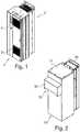
- FIG. 1shows a known motor drive (the terms variable speed drive or variable frequency drive are also used to refer to a motor drive - the terms are used interchangeably in this document), indicated generally by the reference numeral 1.
- Motor drivesgenerate significant heat during use and therefore require cooling.
- the variable speed drive 1 shown in Figure 1includes a back channel 2 that provides the bulk of the cooling for the electrical circuitry within the drive 1. Nevertheless, this is not sufficient and an air inlet 3 and air outlet 4 are provided on the front of the drive to provide an additional air flow for cooling purposes.
- the air inlet 3 and air outlet 4are not blocked. This is not generally a problem when the drive 1 is mounted indoors in a relatively clean environment.
- the air inlets and outletsprovide a weakness in the structure of the cabinet that is particularly problematic if the drive 1 is mounted outdoors (where it may, for example, be required to withstand rain) or in a particularly harsh indoor environment.
- NEMA 3R cabinetstypically involve mounting the drive within the cabinet.
- Fansare typically provided at the bottom of the cabinet to draw air in for cooling the drive. The air is typically expelled out of the side of the cabinet.
- heatersare often provided in order to be able to heat the cabinet to prevent condensation when the drive is not operational.
- Other possible featuresinclude filters and mounting feet to raise the cabinet off the ground.
- Cabinets such as NEMA 3R cabinetsare expensive. Moreover, such cabinets are necessarily larger than the drive that is being enclosed (substantially larger in the case of a typical NEMA 3R implementation). The additional expense and/or the additional space requirements are unacceptable in many circumstances.
- US 2002/0175573 A1discloses a combination of a cover for a motor drive and a motor drive being state of the prior art.
- the present inventionseeks to address at least some of the problems outlined above.
- the present inventionprovides a combination of a cover (typically a partial cover) for a motor drive and a motor drive comprising the features of claim 1.
- a motor drivecomprising an air inlet, an air outlet and a (partial) cover, the cover comprising: a first opening, wherein, in use, air is allowed to pass through the first opening to the air inlet; a second opening, wherein, in use, air is allowed to pass from the air outlet through second opening; and a separator (such as a baffle) inside the cover that is dimensioned and positioned such that, in use, air is prevented from flowing inside the cover from the air outlet to the air inlet.
- a separatorsuch as a baffle
- the rain restrictor"restricts" the ingress of rain into the cover, but does not necessarily prevent the rain from entering the cover completely. This is possible in many forms of the invention because the drive itself provides significant protection from water ingress. What is typically required of the rain restrictor is to prevent very large quantities of water from impacting on the drive in a short space of time, since the drive may not be capable of withstanding such a harsh environment.
- the rain restrictor and/or the separatormay be shaped to direct at least some air from the air outlet away from the cover (in order to reduce the re-circulation of air). Where both are provided, the rain restrictor and the separator may co-operate to direct air from the air outlet away from the cover.
- the coveronly covers a portion of the drive (so that portions of the drive that are not already sufficiently well protected are protected by the cover). This reduces materials, and reduces size requirements, as well as allowing other parts of the drive to be cooled "as normal".
- the rear of the drivemay be uncovered.
- the second openingmay be provided on the front of the cover and, in use, extend parallel to the air outlet.
- the first and/or the second openingmay be on a side of the front cover.
- the separator/bafflemay extend upwards from the second opening to the exterior of the drive.
- the separatormay direct air from the air outlet towards the second opening. If the separator extends upwards from the bottom of the second opening to the air outlet, then air exiting the cover will tend to be directed away from the cover (thereby reducing re-circulation).
- the second openingis provided on the side of the cover (and may extend perpendicular to the air outlet).
- the rain restrictoris provided in the form of a hood provided on the exterior of the cover.
- the hoodis shaped to direct at least some air from the air outlet away from the cover, and is shaped by providing a notch towards the bottom of the hood.
- the rain restrictoris a louvered opening.
- the rain restrictorrestricts the ingress of rain into the cover through the second opening.
- the rain restrictoraddresses one of the problems associated with providing the second opening in the cover.
- the covermay be provided as a kit that, in use, is placed over an existing drive.
- the kitincludes connection means for attaching the cover to the motor drive.
- the inventorshave realized that many of the problems with the prior art can be addressed by providing only a partial cover, wherein the partial cover covers the portions of the drive that are vulnerable, but leaves other portions uncovered. This may be true, for example, where the drives itself provides good protection from, for example, rain, sand or excessive dust.
- the air inlet 3 and air outlet 4need to be covered, but, in many embodiments, the back channel 2 (if provided) does not need to be covered, since the back channel is not vulnerable to rain ingress.
- Figure 2shows the drive of Fig. 1 that is protected with a partial cover 10 in accordance with an aspect of the present invention.
- the cover 10comprises a hood 12, a top 14 and a mounting arrangement 16.
- the mounting arrangement 16is used to physically connect the cover 10 to the drive 1 (for example using screws, as shown in Figure 2 ).
- the hood 12includes a notch 18 that is described in detail below.
- Figure 3shows a partially cut-away view of the drive 1 and cover 10 of Figure 2 .
- Figure 3shows the drive 1, including the back channel 2, air inlet 3 and air outlet 4.
- the cover 10includes the hood 12 (including the notch 18), top 14 and mounting arrangement 16 as shown in Figure 2 .
- the mounting arrangement 16is screwed to the drive 1 so that the cover is held in place, with a gap between the front of the drive 1 and the front of the cover 10. The gap allows air to flow, as described further below.
- the cover 10includes an opening at the bottom, indicated generally by the reference numeral 20, an opening in the front of the cover, indicated generally by the reference numeral 22, and a baffle 24.
- the baffleis connected to the cover 10 (or forms part of the cover) and, in use, is in contact with the front of the drive 1. For reasons described in detail below, the baffle 24 prevents air from flowing between the openings 20 and 22 within the space between the cover 10 and the drive 1.
- Figure 4is a rear view of the cover 10. In Figure 4 , the opening 22 and the baffle 24 are more clearly visible than in Figure 3 .
- the hood 12(which is partially obscured), the top 14 and the mounting arrangement 16 are also shown in Figure 4 .
- cooling airis able to enter drive 1 via the opening 20 and the air inlet 3.
- a fanis typically provided to draw air in through the opening 20.
- Air drawn in through the air inlet 3is used to cool the drive 1 and is then expelled through the air outlet 4. Air expelled through the air outlet 4 is able to leave the vicinity of the drive 1 through the opening 22.
- the provision of the opening 22enables air flow.
- the provision of the hood 12provides protection against rain ingress (and also at least some protection against other contaminants, such as sand). Together, the opening 22 and the hood 12 seek to address the twin problems of rain protection and heat dissipation.
- a further problem with providing a cover for the drive 1is that hot air expelled through the air outlet 4 tends to be directed, by the cover, towards the air inlet 3. This leads to the recirculation of air that has already been heated within the cooling arrangement of the drive. Clearly, this significantly reduces the effectiveness of the cooling arrangement.
- the cover 10partially addresses this problem using the baffle 24.
- the baffleprevents air from flowing from the air outlet 4 to the air inlet 3 in the region between the drive 1 and the cover 10. This arrangement significantly reduces the recirculation of air as all of the air entering the air inlet 3 must enter the cover via the opening 20.
- the baffle 24prevents the recirculation of air within the interior of the cover 10
- air exiting the air outlet 4can recirculate by passing through the opening 22 and then entering the cover via the opening 20.
- the provision of the hood 12tends to direct hot air exiting the opening 22 downwards (i.e. towards the opening 20); accordingly, the hood 12 can add to the problem of recirculation of air outside the cover.
- the cover 10seeks to reduce this external recirculation problem by shaping the hood and/or the baffle to direct air away from the drive (rather the directly downwards). This reduces the tendency of hot air to be recirculated via the inlet.
- the baffleis angled in order to direct the air away from the cover 1 rather than directly downwards.
- the rain hood 12includes a rectangular cutout portion or notch, indicated generally by the reference numeral 18. If the notch in the hood were not provided, air directed by the baffle 24 tends to hit the rain hood and then be redirected downwards. The provision of the notch allows at least some of the air passing through the opening 22 to be directed away from the cover 10.
- the size and shape of the notch shown in Figure 3is provided by way of example; many alternatives will be apparent to the person skilled in the art.
- the problem of recirculationcould be reduced further by increasing the height of the notch, or by simply reducing the size of the rain hood 12.
- the rain hoodis also required to reduce the amount of rain (or other substances) from entering the interior of the cover through the opening 22 and so a balance is required between directing air away from the cover and preventing rain from entering through the opening 22.
- the optimum balancemay vary from application to application.
- the position of the air inlet 3 and/or air outlet 4 as shown in attached Figuresis not essential to all forms of the invention.
- at least one of the inlet and outletcould be provided on the side of the drive (rather than on the front).
- at least one of the inlet and outletcould be provided on the top and/or the bottom of the drive.
- the air inlet 3is provided towards the bottom of the drive 1 and the air outlet 4 is provided near the top of the drive; these positions could be reversed.
- Other possible variantswill be apparent to the person skilled in the art.
- the baffle 24act as separators that prevent air from re-circulating within the cover from the outlet to the inlet of the drive. This is a particular problem with the configurations shown in Figures in which the air inlet 3 and the air outlet 4 are both provided on the front of the drive. Clearly, if the air inlet and air outlet are not both provided on the front of the drive, then the problem of air re-circulation may be significantly reduced.
- a rain restrictor(such as the hood 12) is provided to reduce the amount of rain that enters the interior of the cover, thereby reducing the likelihood of rain entering the air outlet 4.
- the restriction of rainis often required in order to enable the drive/cover assembly to be sufficiently water-resistant.
Landscapes
- Engineering & Computer Science (AREA)
- Power Engineering (AREA)
- Housings, Intake/Discharge, And Installation Of Fluid Heaters (AREA)
- Motor Or Generator Frames (AREA)
- Air-Flow Control Members (AREA)
Description
- The present invention relates to a cover for a motor drive. The cover may, for example, provide additional protection for the motor drive in order to enable the drive to be placed outside in potentially hostile conditions.
Figure 1 shows a known motor drive (the terms variable speed drive or variable frequency drive are also used to refer to a motor drive - the terms are used interchangeably in this document), indicated generally by thereference numeral 1. Motor drives generate significant heat during use and therefore require cooling. Thevariable speed drive 1 shown inFigure 1 includes aback channel 2 that provides the bulk of the cooling for the electrical circuitry within thedrive 1. Nevertheless, this is not sufficient and anair inlet 3 andair outlet 4 are provided on the front of the drive to provide an additional air flow for cooling purposes.- In order for sufficient cooling to be provided, it is important that the
air inlet 3 andair outlet 4 are not blocked. This is not generally a problem when thedrive 1 is mounted indoors in a relatively clean environment. However, the air inlets and outlets provide a weakness in the structure of the cabinet that is particularly problematic if thedrive 1 is mounted outdoors (where it may, for example, be required to withstand rain) or in a particularly harsh indoor environment. - It is possible to mount the
drive 1 within an enclosure box in order to protect the drive from, for example, rain, sand or excessive dust. However, such an enclosure must allow sufficient air to flow into theair inlet 3 and away from theair outlet 4, otherwise the thermal performance of thedrive 1 will be adversely affected. - A known solution to this problem is to provide a cabinet to protect the
drive 1. A commonly used cabinet is the so-called NEMA 3R cabinet (as rated by the National Electrical Manufacturers Association). NEMA 3R cabinets typically involve mounting the drive within the cabinet. Fans are typically provided at the bottom of the cabinet to draw air in for cooling the drive. The air is typically expelled out of the side of the cabinet. In addition to cooling fans, heaters are often provided in order to be able to heat the cabinet to prevent condensation when the drive is not operational. Other possible features include filters and mounting feet to raise the cabinet off the ground. - Cabinets such as NEMA 3R cabinets are expensive. Moreover, such cabinets are necessarily larger than the drive that is being enclosed (substantially larger in the case of a typical NEMA 3R implementation). The additional expense and/or the additional space requirements are unacceptable in many circumstances.
US 2002/0175573 A1 discloses a combination of a cover for a motor drive and a motor drive being state of the prior art.- The present invention seeks to address at least some of the problems outlined above.
- The present invention provides a combination of a cover (typically a partial cover) for a motor drive and a motor drive comprising the features of
claim 1. - In an example not falling under the scope of the present invention there is further provided a motor drive comprising an air inlet, an air outlet and a (partial) cover, the cover comprising: a first opening, wherein, in use, air is allowed to pass through the first opening to the air inlet; a second opening, wherein, in use, air is allowed to pass from the air outlet through second opening; and a separator (such as a baffle) inside the cover that is dimensioned and positioned such that, in use, air is prevented from flowing inside the cover from the air outlet to the air inlet.
- Where provided, the rain restrictor "restricts" the ingress of rain into the cover, but does not necessarily prevent the rain from entering the cover completely. This is possible in many forms of the invention because the drive itself provides significant protection from water ingress. What is typically required of the rain restrictor is to prevent very large quantities of water from impacting on the drive in a short space of time, since the drive may not be capable of withstanding such a harsh environment.
- The rain restrictor and/or the separator may be shaped to direct at least some air from the air outlet away from the cover (in order to reduce the re-circulation of air). Where both are provided, the rain restrictor and the separator may co-operate to direct air from the air outlet away from the cover.
- In many forms of the invention, the cover only covers a portion of the drive (so that portions of the drive that are not already sufficiently well protected are protected by the cover). This reduces materials, and reduces size requirements, as well as allowing other parts of the drive to be cooled "as normal". By way of example, the rear of the drive may be uncovered.
- The second opening may be provided on the front of the cover and, in use, extend parallel to the air outlet. The first and/or the second opening may be on a side of the front cover.
- The separator/baffle may extend upwards from the second opening to the exterior of the drive. Thus, the separator may direct air from the air outlet towards the second opening. If the separator extends upwards from the bottom of the second opening to the air outlet, then air exiting the cover will tend to be directed away from the cover (thereby reducing re-circulation).
- In an alternative form of the invention, the second opening is provided on the side of the cover (and may extend perpendicular to the air outlet).
- The rain restrictor is provided in the form of a hood provided on the exterior of the cover. The hood is shaped to direct at least some air from the air outlet away from the cover, and is shaped by providing a notch towards the bottom of the hood.
- In an example not falling under the present invention, the rain restrictor is a louvered opening.
- The rain restrictor restricts the ingress of rain into the cover through the second opening. Thus, the rain restrictor addresses one of the problems associated with providing the second opening in the cover.
- The cover may be provided as a kit that, in use, is placed over an existing drive. The kit includes connection means for attaching the cover to the motor drive.
- The invention will now be described in further detail with reference to the following schematic drawings, in which:
Figure 1 shows a known variable speed drive;Figure 2 shows the drive ofFig. 1 that is protected with a partial cover in accordance with an aspect of the present invention;Figure 3 is a partially cut-away view of the drive and cover ofFig. 2 ; andFigure 4 is a rear view of a cover in accordance with an aspect of the present invention;- The inventors have realized that many of the problems with the prior art can be addressed by providing only a partial cover, wherein the partial cover covers the portions of the drive that are vulnerable, but leaves other portions uncovered. This may be true, for example, where the drives itself provides good protection from, for example, rain, sand or excessive dust.
- In particular, the
air inlet 3 andair outlet 4 need to be covered, but, in many embodiments, the back channel 2 (if provided) does not need to be covered, since the back channel is not vulnerable to rain ingress. - Providing a partial cover reduces cost (by reducing material requirements) and also reduces size. However, dealing with heat generation by the drive is not trivial as any covering of the drive reduces the scope for heat removal.
Figure 2 shows the drive ofFig. 1 that is protected with apartial cover 10 in accordance with an aspect of the present invention.- The
cover 10 comprises ahood 12, atop 14 and amounting arrangement 16. Themounting arrangement 16 is used to physically connect thecover 10 to the drive 1 (for example using screws, as shown inFigure 2 ). Thehood 12 includes anotch 18 that is described in detail below. Figure 3 shows a partially cut-away view of thedrive 1 and cover 10 ofFigure 2 .Figure 3 shows thedrive 1, including theback channel 2,air inlet 3 andair outlet 4. Thecover 10 includes the hood 12 (including the notch 18), top 14 and mountingarrangement 16 as shown inFigure 2 . As shown inFigure 3 , the mountingarrangement 16 is screwed to thedrive 1 so that the cover is held in place, with a gap between the front of thedrive 1 and the front of thecover 10. The gap allows air to flow, as described further below.- The
cover 10 includes an opening at the bottom, indicated generally by thereference numeral 20, an opening in the front of the cover, indicated generally by thereference numeral 22, and abaffle 24. The baffle is connected to the cover 10 (or forms part of the cover) and, in use, is in contact with the front of thedrive 1. For reasons described in detail below, thebaffle 24 prevents air from flowing between theopenings cover 10 and thedrive 1. Figure 4 is a rear view of thecover 10. InFigure 4 , theopening 22 and thebaffle 24 are more clearly visible than inFigure 3 . The hood 12 (which is partially obscured), the top 14 and the mountingarrangement 16 are also shown inFigure 4 .- When the
cover 10 is attached to the drive, cooling air is able to enterdrive 1 via theopening 20 and theair inlet 3. A fan is typically provided to draw air in through theopening 20. - Air drawn in through the
air inlet 3 is used to cool thedrive 1 and is then expelled through theair outlet 4. Air expelled through theair outlet 4 is able to leave the vicinity of thedrive 1 through theopening 22. - As described above, a disadvantage with the provision of the
air inlet 3 and theair outlet 4 is that when used outdoors without a cover, rain can enter the inlets and outlets and potentially damage the drive. Providing a cover addresses this problem, but prevents air flow. - The provision of the
opening 22 enables air flow. The provision of thehood 12 provides protection against rain ingress (and also at least some protection against other contaminants, such as sand). Together, theopening 22 and thehood 12 seek to address the twin problems of rain protection and heat dissipation. - A further problem with providing a cover for the
drive 1 is that hot air expelled through theair outlet 4 tends to be directed, by the cover, towards theair inlet 3. This leads to the recirculation of air that has already been heated within the cooling arrangement of the drive. Clearly, this significantly reduces the effectiveness of the cooling arrangement. - The
cover 10 partially addresses this problem using thebaffle 24. The baffle prevents air from flowing from theair outlet 4 to theair inlet 3 in the region between thedrive 1 and thecover 10. This arrangement significantly reduces the recirculation of air as all of the air entering theair inlet 3 must enter the cover via theopening 20. - Although the
baffle 24 prevents the recirculation of air within the interior of thecover 10, air exiting theair outlet 4 can recirculate by passing through theopening 22 and then entering the cover via theopening 20. The provision of thehood 12 tends to direct hot air exiting theopening 22 downwards (i.e. towards the opening 20); accordingly, thehood 12 can add to the problem of recirculation of air outside the cover. - The
cover 10 seeks to reduce this external recirculation problem by shaping the hood and/or the baffle to direct air away from the drive (rather the directly downwards). This reduces the tendency of hot air to be recirculated via the inlet. - As shown in
Figures 3 and 4 , the baffle is angled in order to direct the air away from thecover 1 rather than directly downwards. - As shown in
Figure 3 , therain hood 12 includes a rectangular cutout portion or notch, indicated generally by thereference numeral 18. If the notch in the hood were not provided, air directed by thebaffle 24 tends to hit the rain hood and then be redirected downwards. The provision of the notch allows at least some of the air passing through theopening 22 to be directed away from thecover 10. The size and shape of the notch shown inFigure 3 is provided by way of example; many alternatives will be apparent to the person skilled in the art. - The problem of recirculation could be reduced further by increasing the height of the notch, or by simply reducing the size of the
rain hood 12. However, the rain hood is also required to reduce the amount of rain (or other substances) from entering the interior of the cover through theopening 22 and so a balance is required between directing air away from the cover and preventing rain from entering through theopening 22. The optimum balance may vary from application to application. - The position of the
air inlet 3 and/orair outlet 4 as shown in attached Figures is not essential to all forms of the invention. For example, at least one of the inlet and outlet could be provided on the side of the drive (rather than on the front). Furthermore, at least one of the inlet and outlet could be provided on the top and/or the bottom of the drive. In the arrangements described above, theair inlet 3 is provided towards the bottom of thedrive 1 and theair outlet 4 is provided near the top of the drive; these positions could be reversed. Other possible variants will be apparent to the person skilled in the art. - As described above, the
baffle 24 act as separators that prevent air from re-circulating within the cover from the outlet to the inlet of the drive. This is a particular problem with the configurations shown in Figures in which theair inlet 3 and theair outlet 4 are both provided on the front of the drive. Clearly, if the air inlet and air outlet are not both provided on the front of the drive, then the problem of air re-circulation may be significantly reduced. - As described above, a rain restrictor (such as the hood 12) is provided to reduce the amount of rain that enters the interior of the cover, thereby reducing the likelihood of rain entering the
air outlet 4. The restriction of rain is often required in order to enable the drive/cover assembly to be sufficiently water-resistant. - The
prior art drive 1 described above with reference toFigure 1 includes backchannel cooling. It should be stressed that although the provision of backchannel cooling has many advantages for use with the principles of the present invention, it is not essential to all forms of the invention.
Claims (8)
- A combination of a cover (10) for a motor drive (1) and a motor drive (1), wherein the drive includes an air inlet (3) and an air outlet (4), the cover (10) comprising:a first opening (20), wherein, in use, air is allowed to pass through the first opening (20) to the air inlet (3);a second opening (22), wherein, in use, air is allowed to pass from the air outlet (4) through second opening (22); anda separator (24) inside the cover (10) that is dimensioned and positioned such that, in use, air is prevented from flowing inside the cover (10) from the air outlet (4) to the air inlet (3); and a rain restrictor that restricts the ingress of rain into the cover, wherein said rain restrictor is a hood (12) provided on the exterior of the cover (10), and wherein the hood (12) is shaped to direct at least some air from the air outlet (4) away from the cover (10),characterized in that the hood (12) is shaped by providing a notch (18) towards the bottom of the hood (12).
- A combination as claimed in claim 1, wherein the separator (24) is shaped to direct at least some air from the air outlet (4) away from the cover (10).
- A combination as claimed in claim 1 or claim 2, wherein the second opening (22) is provided on the front of the cover (10) and, in use, extends parallel to the air outlet (4).
- A combination as claimed in claim 3, wherein the separator (24) extends upwards from the second opening (22) to the exterior of the drive (1).
- A combination as claimed in claim 1, wherein the hood (12) is shaped by providing a projection (34) towards the bottom of the hood (12) that extends, at an angle, away from the plane of the cover (10).
- A combination as claimed in any one of claims 1 to 5, wherein said rain restrictor is provided to restrict the ingress of rain into the cover (10) through the second opening (22).
- A combination as claimed in any preceding claim, wherein the cover (10) only covers a portion of the drive (1).
- A combination as claimed in claim 7, wherein the rear of the drive (1) is uncovered.
Applications Claiming Priority (2)
| Application Number | Priority Date | Filing Date | Title |
|---|---|---|---|
| US201361861184P | 2013-08-01 | 2013-08-01 | |
| PCT/IB2014/062153WO2015015329A2 (en) | 2013-08-01 | 2014-06-12 | Motor drive cover |
Publications (2)
| Publication Number | Publication Date |
|---|---|
| EP3028370A2 EP3028370A2 (en) | 2016-06-08 |
| EP3028370B1true EP3028370B1 (en) | 2021-09-08 |
Family
ID=51168302
Family Applications (1)
| Application Number | Title | Priority Date | Filing Date |
|---|---|---|---|
| EP14737325.2AActiveEP3028370B1 (en) | 2013-08-01 | 2014-06-12 | Motor drive cover |
Country Status (4)
| Country | Link |
|---|---|
| US (1) | US10447107B2 (en) |
| EP (1) | EP3028370B1 (en) |
| CN (1) | CN105409099B (en) |
| WO (1) | WO2015015329A2 (en) |
Families Citing this family (6)
| Publication number | Priority date | Publication date | Assignee | Title |
|---|---|---|---|---|
| EP3028370B1 (en)* | 2013-08-01 | 2021-09-08 | Danfoss Power Electronics A/S | Motor drive cover |
| CN105827858A (en)* | 2016-05-10 | 2016-08-03 | 南京铁道职业技术学院 | Smart phone Bluetooth infrared meter reading system and method for improved electric energy meter |
| USD944204S1 (en) | 2019-07-01 | 2022-02-22 | Nidec Motor Corporation | Motor controller housing |
| USD920914S1 (en) | 2019-07-01 | 2021-06-01 | Nidec Motor Corporation | Motor air scoop |
| DE102021116812A1 (en)* | 2021-06-30 | 2023-01-05 | Vertiv S.R.L. | EXPANSION KIT |
| US12222132B2 (en)* | 2023-03-11 | 2025-02-11 | Lacroix Industries, Inc. | Protective cover for ductless mini split air conditioners |
Family Cites Families (27)
| Publication number | Priority date | Publication date | Assignee | Title |
|---|---|---|---|---|
| US3364838A (en)* | 1966-02-01 | 1968-01-23 | Gen Electric | Cabinet for mounting, enclosing and cooling electrical apparatus |
| DE2048255A1 (en)* | 1970-10-01 | 1972-04-06 | Bbc Brown Boveri & Cie | |
| US4726198A (en)* | 1987-03-27 | 1988-02-23 | Ouwenga John N | Centrifugal heat exchanger |
| US4759196A (en)* | 1987-05-26 | 1988-07-26 | American Standard Inc. | Two-position cover for air handling equipment enclosure |
| US5266856A (en)* | 1992-11-30 | 1993-11-30 | Siemens Energy & Automation, Inc. | Vibration reduction for electric motors |
| DE19515252A1 (en)* | 1995-04-26 | 1996-11-07 | Vorwerk Co Interholding | Electric motor with casing protecting against moisture ingress |
| US5886868A (en) | 1996-10-10 | 1999-03-23 | Eaton Corporation | Electrical distribution panel enclosure |
| US6105875A (en)* | 1998-09-08 | 2000-08-22 | Lucent Technologies, Inc. | Direct air cooling of outdoor electronic cabinets |
| US5944595A (en)* | 1998-11-18 | 1999-08-31 | Prothro; Glenn J. | Feather picking device |
| US6703730B2 (en)* | 2001-05-24 | 2004-03-09 | Asmo Co., Ltd. | Electric motor cooling having air-communication restrain between intake duct and exhaust duct, and having cooling fan received in yoke |
| US6643130B1 (en)* | 2002-07-08 | 2003-11-04 | Demarchis John A. | Wash down filtered fan apparatus |
| US6889752B2 (en)* | 2002-07-11 | 2005-05-10 | Avaya Technology Corp. | Systems and methods for weatherproof cabinets with multiple compartment cooling |
| EP1548916B1 (en)* | 2002-09-13 | 2008-07-02 | Aisin Aw Co., Ltd. | Drive device |
| US6879483B2 (en) | 2003-08-29 | 2005-04-12 | Eaton Corporation | Outdoor electrical enclosure and hood therefor |
| US7075003B2 (en) | 2004-07-01 | 2006-07-11 | Eaton Corporation | Outdoor electrical enclosure and moisture-resistant flange and side assembly structures therefor |
| CA2510529C (en)* | 2005-06-20 | 2013-08-27 | Emerson Network Power, Energy Systems, North America, Inc. | Electromagnet-assisted ventilation cover for an electronic equipment enclosure |
| US7543793B2 (en)* | 2005-12-21 | 2009-06-09 | Graham Wayne A | Generator set tank and enclosure with adjustable mounting system |
| US8590602B2 (en)* | 2007-06-12 | 2013-11-26 | Asymblix, Llc | Heat exchanger for outdoor enclosures |
| DE102008016889B4 (en) | 2008-04-02 | 2014-03-20 | Siemens Aktiengesellschaft | Housing attachment for an electrical machine with degree of protection IP 24W |
| US8800403B2 (en)* | 2010-09-17 | 2014-08-12 | Nicholas A. Gargaro, III | Boat lift drive housing apparatus |
| US20120083196A1 (en)* | 2010-10-01 | 2012-04-05 | Peter Leslie Gregory Mockridge | System and Method for Conditioning Air |
| CN202231982U (en) | 2011-08-25 | 2012-05-23 | 三垦力达电气(江阴)有限公司 | A waterproof operating panel for indoor outer electrical equipment |
| CN102325436A (en) | 2011-09-15 | 2012-01-18 | 无锡山亿新能源科技有限公司 | Protecting device of display operation region of outdoor inverter |
| CA2763183A1 (en)* | 2012-01-05 | 2013-07-05 | Pumpwell Solutions Ltd. | Vent cover |
| DE102012219122A1 (en)* | 2012-10-19 | 2014-04-24 | Siemens Aktiengesellschaft | Electric machine and method for cooling an electrical machine |
| CN202931111U (en)* | 2012-11-29 | 2013-05-08 | 湘潭电机股份有限公司 | Fan housing for open-type climate protective type motor |
| EP3028370B1 (en)* | 2013-08-01 | 2021-09-08 | Danfoss Power Electronics A/S | Motor drive cover |
- 2014
- 2014-06-12EPEP14737325.2Apatent/EP3028370B1/enactiveActive
- 2014-06-12WOPCT/IB2014/062153patent/WO2015015329A2/enactiveApplication Filing
- 2014-06-12CNCN201480042462.8Apatent/CN105409099B/enactiveActive
- 2014-06-12USUS14/907,912patent/US10447107B2/enactiveActive
Also Published As
| Publication number | Publication date |
|---|---|
| WO2015015329A2 (en) | 2015-02-05 |
| US10447107B2 (en) | 2019-10-15 |
| CN105409099A (en) | 2016-03-16 |
| WO2015015329A3 (en) | 2015-05-14 |
| EP3028370A2 (en) | 2016-06-08 |
| US20160172926A1 (en) | 2016-06-16 |
| CN105409099B (en) | 2018-04-27 |
Similar Documents
| Publication | Publication Date | Title |
|---|---|---|
| EP3028370B1 (en) | Motor drive cover | |
| US8590602B2 (en) | Heat exchanger for outdoor enclosures | |
| US7453696B2 (en) | Cooling device for a radial fan driven by an electric motor with IC | |
| US11015617B2 (en) | Rear guard of box fan and box fan | |
| CN206674404U (en) | Tube tower and base station | |
| KR101468874B1 (en) | The emergency protection apparatus of the server rack | |
| EP3102014B1 (en) | Arrangement for cooling a cabinet | |
| CN216852950U (en) | Electrical control cabinet and oil smoke clarifier | |
| CN209299599U (en) | A dust-proof and heat-dissipating communication cabinet | |
| JP4958264B2 (en) | Electrical and electronic equipment storage cabinet | |
| JP2004044962A (en) | Cooling device | |
| CN209150553U (en) | A kind of novel explosion-proof distribution box | |
| CN220755341U (en) | Equipment compartment air duct system of outdoor energy storage cabinet | |
| JP7094355B2 (en) | Outdoor unit of air conditioner | |
| CN110571675A (en) | A multifunctional low-voltage distribution box | |
| CN205191779U (en) | Air conditioner outdoor unit and air conditioner | |
| JP2002151874A (en) | Power converter | |
| CN209930662U (en) | Control cabinet with protective device | |
| CN223005059U (en) | Electric control box and air conditioner outdoor unit | |
| CN210074528U (en) | Dustproof heat dissipation formula power distribution box | |
| CN222381098U (en) | A power distribution box for power equipment used in safe production | |
| EP3923688B1 (en) | Fire shield for variable frequency drive enclosure | |
| CN219893574U (en) | Ventilating box body and electric cabinet | |
| CN219739738U (en) | Weak current intelligent control cabinet | |
| CN222462527U (en) | An external DC reactor |
Legal Events
| Date | Code | Title | Description |
|---|---|---|---|
| PUAI | Public reference made under article 153(3) epc to a published international application that has entered the european phase | Free format text:ORIGINAL CODE: 0009012 | |
| 17P | Request for examination filed | Effective date:20160107 | |
| AK | Designated contracting states | Kind code of ref document:A2 Designated state(s):AL AT BE BG CH CY CZ DE DK EE ES FI FR GB GR HR HU IE IS IT LI LT LU LV MC MK MT NL NO PL PT RO RS SE SI SK SM TR | |
| AX | Request for extension of the european patent | Extension state:BA ME | |
| RIN1 | Information on inventor provided before grant (corrected) | Inventor name:STOUTENBOROUGH, ERIC VON Inventor name:MILLER, GEORGE Inventor name:DRABEK, RYAN Inventor name:GRAY, MATTHEW Inventor name:GRZESIK, LESTER Inventor name:JOHANSEN, FRANK-ERIK | |
| DAX | Request for extension of the european patent (deleted) | ||
| STAA | Information on the status of an ep patent application or granted ep patent | Free format text:STATUS: EXAMINATION IS IN PROGRESS | |
| 17Q | First examination report despatched | Effective date:20180425 | |
| GRAP | Despatch of communication of intention to grant a patent | Free format text:ORIGINAL CODE: EPIDOSNIGR1 | |
| STAA | Information on the status of an ep patent application or granted ep patent | Free format text:STATUS: GRANT OF PATENT IS INTENDED | |
| INTG | Intention to grant announced | Effective date:20210504 | |
| GRAS | Grant fee paid | Free format text:ORIGINAL CODE: EPIDOSNIGR3 | |
| GRAA | (expected) grant | Free format text:ORIGINAL CODE: 0009210 | |
| STAA | Information on the status of an ep patent application or granted ep patent | Free format text:STATUS: THE PATENT HAS BEEN GRANTED | |
| AK | Designated contracting states | Kind code of ref document:B1 Designated state(s):AL AT BE BG CH CY CZ DE DK EE ES FI FR GB GR HR HU IE IS IT LI LT LU LV MC MK MT NL NO PL PT RO RS SE SI SK SM TR | |
| REG | Reference to a national code | Ref country code:GB Ref legal event code:FG4D | |
| REG | Reference to a national code | Ref country code:CH Ref legal event code:EP Ref country code:AT Ref legal event code:REF Ref document number:1429442 Country of ref document:AT Kind code of ref document:T Effective date:20210915 | |
| REG | Reference to a national code | Ref country code:DE Ref legal event code:R096 Ref document number:602014079982 Country of ref document:DE | |
| REG | Reference to a national code | Ref country code:IE Ref legal event code:FG4D | |
| REG | Reference to a national code | Ref country code:LT Ref legal event code:MG9D | |
| REG | Reference to a national code | Ref country code:NL Ref legal event code:MP Effective date:20210908 | |
| PG25 | Lapsed in a contracting state [announced via postgrant information from national office to epo] | Ref country code:HR Free format text:LAPSE BECAUSE OF FAILURE TO SUBMIT A TRANSLATION OF THE DESCRIPTION OR TO PAY THE FEE WITHIN THE PRESCRIBED TIME-LIMIT Effective date:20210908 Ref country code:RS Free format text:LAPSE BECAUSE OF FAILURE TO SUBMIT A TRANSLATION OF THE DESCRIPTION OR TO PAY THE FEE WITHIN THE PRESCRIBED TIME-LIMIT Effective date:20210908 Ref country code:SE Free format text:LAPSE BECAUSE OF FAILURE TO SUBMIT A TRANSLATION OF THE DESCRIPTION OR TO PAY THE FEE WITHIN THE PRESCRIBED TIME-LIMIT Effective date:20210908 Ref country code:FI Free format text:LAPSE BECAUSE OF FAILURE TO SUBMIT A TRANSLATION OF THE DESCRIPTION OR TO PAY THE FEE WITHIN THE PRESCRIBED TIME-LIMIT Effective date:20210908 Ref country code:ES Free format text:LAPSE BECAUSE OF FAILURE TO SUBMIT A TRANSLATION OF THE DESCRIPTION OR TO PAY THE FEE WITHIN THE PRESCRIBED TIME-LIMIT Effective date:20210908 Ref country code:NO Free format text:LAPSE BECAUSE OF FAILURE TO SUBMIT A TRANSLATION OF THE DESCRIPTION OR TO PAY THE FEE WITHIN THE PRESCRIBED TIME-LIMIT Effective date:20211208 Ref country code:LT Free format text:LAPSE BECAUSE OF FAILURE TO SUBMIT A TRANSLATION OF THE DESCRIPTION OR TO PAY THE FEE WITHIN THE PRESCRIBED TIME-LIMIT Effective date:20210908 Ref country code:BG Free format text:LAPSE BECAUSE OF FAILURE TO SUBMIT A TRANSLATION OF THE DESCRIPTION OR TO PAY THE FEE WITHIN THE PRESCRIBED TIME-LIMIT Effective date:20211208 | |
| REG | Reference to a national code | Ref country code:AT Ref legal event code:MK05 Ref document number:1429442 Country of ref document:AT Kind code of ref document:T Effective date:20210908 | |
| PG25 | Lapsed in a contracting state [announced via postgrant information from national office to epo] | Ref country code:LV Free format text:LAPSE BECAUSE OF FAILURE TO SUBMIT A TRANSLATION OF THE DESCRIPTION OR TO PAY THE FEE WITHIN THE PRESCRIBED TIME-LIMIT Effective date:20210908 Ref country code:GR Free format text:LAPSE BECAUSE OF FAILURE TO SUBMIT A TRANSLATION OF THE DESCRIPTION OR TO PAY THE FEE WITHIN THE PRESCRIBED TIME-LIMIT Effective date:20211209 | |
| PG25 | Lapsed in a contracting state [announced via postgrant information from national office to epo] | Ref country code:AT Free format text:LAPSE BECAUSE OF FAILURE TO SUBMIT A TRANSLATION OF THE DESCRIPTION OR TO PAY THE FEE WITHIN THE PRESCRIBED TIME-LIMIT Effective date:20210908 | |
| PG25 | Lapsed in a contracting state [announced via postgrant information from national office to epo] | Ref country code:IS Free format text:LAPSE BECAUSE OF FAILURE TO SUBMIT A TRANSLATION OF THE DESCRIPTION OR TO PAY THE FEE WITHIN THE PRESCRIBED TIME-LIMIT Effective date:20220108 Ref country code:SM Free format text:LAPSE BECAUSE OF FAILURE TO SUBMIT A TRANSLATION OF THE DESCRIPTION OR TO PAY THE FEE WITHIN THE PRESCRIBED TIME-LIMIT Effective date:20210908 Ref country code:SK Free format text:LAPSE BECAUSE OF FAILURE TO SUBMIT A TRANSLATION OF THE DESCRIPTION OR TO PAY THE FEE WITHIN THE PRESCRIBED TIME-LIMIT Effective date:20210908 Ref country code:RO Free format text:LAPSE BECAUSE OF FAILURE TO SUBMIT A TRANSLATION OF THE DESCRIPTION OR TO PAY THE FEE WITHIN THE PRESCRIBED TIME-LIMIT Effective date:20210908 Ref country code:PT Free format text:LAPSE BECAUSE OF FAILURE TO SUBMIT A TRANSLATION OF THE DESCRIPTION OR TO PAY THE FEE WITHIN THE PRESCRIBED TIME-LIMIT Effective date:20220110 Ref country code:PL Free format text:LAPSE BECAUSE OF FAILURE TO SUBMIT A TRANSLATION OF THE DESCRIPTION OR TO PAY THE FEE WITHIN THE PRESCRIBED TIME-LIMIT Effective date:20210908 Ref country code:NL Free format text:LAPSE BECAUSE OF FAILURE TO SUBMIT A TRANSLATION OF THE DESCRIPTION OR TO PAY THE FEE WITHIN THE PRESCRIBED TIME-LIMIT Effective date:20210908 Ref country code:EE Free format text:LAPSE BECAUSE OF FAILURE TO SUBMIT A TRANSLATION OF THE DESCRIPTION OR TO PAY THE FEE WITHIN THE PRESCRIBED TIME-LIMIT Effective date:20210908 Ref country code:CZ Free format text:LAPSE BECAUSE OF FAILURE TO SUBMIT A TRANSLATION OF THE DESCRIPTION OR TO PAY THE FEE WITHIN THE PRESCRIBED TIME-LIMIT Effective date:20210908 Ref country code:AL Free format text:LAPSE BECAUSE OF FAILURE TO SUBMIT A TRANSLATION OF THE DESCRIPTION OR TO PAY THE FEE WITHIN THE PRESCRIBED TIME-LIMIT Effective date:20210908 | |
| REG | Reference to a national code | Ref country code:DE Ref legal event code:R097 Ref document number:602014079982 Country of ref document:DE | |
| PLBE | No opposition filed within time limit | Free format text:ORIGINAL CODE: 0009261 | |
| STAA | Information on the status of an ep patent application or granted ep patent | Free format text:STATUS: NO OPPOSITION FILED WITHIN TIME LIMIT | |
| PG25 | Lapsed in a contracting state [announced via postgrant information from national office to epo] | Ref country code:DK Free format text:LAPSE BECAUSE OF FAILURE TO SUBMIT A TRANSLATION OF THE DESCRIPTION OR TO PAY THE FEE WITHIN THE PRESCRIBED TIME-LIMIT Effective date:20210908 | |
| 26N | No opposition filed | Effective date:20220609 | |
| PG25 | Lapsed in a contracting state [announced via postgrant information from national office to epo] | Ref country code:SI Free format text:LAPSE BECAUSE OF FAILURE TO SUBMIT A TRANSLATION OF THE DESCRIPTION OR TO PAY THE FEE WITHIN THE PRESCRIBED TIME-LIMIT Effective date:20210908 | |
| PG25 | Lapsed in a contracting state [announced via postgrant information from national office to epo] | Ref country code:MC Free format text:LAPSE BECAUSE OF FAILURE TO SUBMIT A TRANSLATION OF THE DESCRIPTION OR TO PAY THE FEE WITHIN THE PRESCRIBED TIME-LIMIT Effective date:20210908 Ref country code:IT Free format text:LAPSE BECAUSE OF FAILURE TO SUBMIT A TRANSLATION OF THE DESCRIPTION OR TO PAY THE FEE WITHIN THE PRESCRIBED TIME-LIMIT Effective date:20210908 | |
| REG | Reference to a national code | Ref country code:CH Ref legal event code:PL | |
| REG | Reference to a national code | Ref country code:BE Ref legal event code:MM Effective date:20220630 | |
| GBPC | Gb: european patent ceased through non-payment of renewal fee | Effective date:20220612 | |
| PG25 | Lapsed in a contracting state [announced via postgrant information from national office to epo] | Ref country code:LU Free format text:LAPSE BECAUSE OF NON-PAYMENT OF DUE FEES Effective date:20220612 Ref country code:LI Free format text:LAPSE BECAUSE OF NON-PAYMENT OF DUE FEES Effective date:20220630 Ref country code:IE Free format text:LAPSE BECAUSE OF NON-PAYMENT OF DUE FEES Effective date:20220612 Ref country code:FR Free format text:LAPSE BECAUSE OF NON-PAYMENT OF DUE FEES Effective date:20220630 Ref country code:CH Free format text:LAPSE BECAUSE OF NON-PAYMENT OF DUE FEES Effective date:20220630 | |
| PG25 | Lapsed in a contracting state [announced via postgrant information from national office to epo] | Ref country code:GB Free format text:LAPSE BECAUSE OF NON-PAYMENT OF DUE FEES Effective date:20220612 Ref country code:BE Free format text:LAPSE BECAUSE OF NON-PAYMENT OF DUE FEES Effective date:20220630 | |
| P01 | Opt-out of the competence of the unified patent court (upc) registered | Effective date:20230617 | |
| PG25 | Lapsed in a contracting state [announced via postgrant information from national office to epo] | Ref country code:HU Free format text:LAPSE BECAUSE OF FAILURE TO SUBMIT A TRANSLATION OF THE DESCRIPTION OR TO PAY THE FEE WITHIN THE PRESCRIBED TIME-LIMIT; INVALID AB INITIO Effective date:20140612 | |
| PG25 | Lapsed in a contracting state [announced via postgrant information from national office to epo] | Ref country code:MK Free format text:LAPSE BECAUSE OF FAILURE TO SUBMIT A TRANSLATION OF THE DESCRIPTION OR TO PAY THE FEE WITHIN THE PRESCRIBED TIME-LIMIT Effective date:20210908 Ref country code:CY Free format text:LAPSE BECAUSE OF FAILURE TO SUBMIT A TRANSLATION OF THE DESCRIPTION OR TO PAY THE FEE WITHIN THE PRESCRIBED TIME-LIMIT Effective date:20210908 | |
| PG25 | Lapsed in a contracting state [announced via postgrant information from national office to epo] | Ref country code:MT Free format text:LAPSE BECAUSE OF FAILURE TO SUBMIT A TRANSLATION OF THE DESCRIPTION OR TO PAY THE FEE WITHIN THE PRESCRIBED TIME-LIMIT Effective date:20210908 | |
| PGFP | Annual fee paid to national office [announced via postgrant information from national office to epo] | Ref country code:DE Payment date:20250507 Year of fee payment:12 |