EP3026874B1 - Body fluid testing component for analyte detection - Google Patents
Body fluid testing component for analyte detectionDownload PDFInfo
- Publication number
- EP3026874B1 EP3026874B1EP15200495.8AEP15200495AEP3026874B1EP 3026874 B1EP3026874 B1EP 3026874B1EP 15200495 AEP15200495 AEP 15200495AEP 3026874 B1EP3026874 B1EP 3026874B1
- Authority
- EP
- European Patent Office
- Prior art keywords
- analyte
- test strip
- casing
- testing device
- camera lens
- Prior art date
- Legal status (The legal status is an assumption and is not a legal conclusion. Google has not performed a legal analysis and makes no representation as to the accuracy of the status listed.)
- Active
Links
Images


Classifications
- G—PHYSICS
- G01—MEASURING; TESTING
- G01N—INVESTIGATING OR ANALYSING MATERIALS BY DETERMINING THEIR CHEMICAL OR PHYSICAL PROPERTIES
- G01N33/00—Investigating or analysing materials by specific methods not covered by groups G01N1/00 - G01N31/00
- G01N33/48—Biological material, e.g. blood, urine; Haemocytometers
- G01N33/483—Physical analysis of biological material
- G01N33/487—Physical analysis of biological material of liquid biological material
- G01N33/48785—Electrical and electronic details of measuring devices for physical analysis of liquid biological material not specific to a particular test method, e.g. user interface or power supply
- G—PHYSICS
- G01—MEASURING; TESTING
- G01N—INVESTIGATING OR ANALYSING MATERIALS BY DETERMINING THEIR CHEMICAL OR PHYSICAL PROPERTIES
- G01N21/00—Investigating or analysing materials by the use of optical means, i.e. using sub-millimetre waves, infrared, visible or ultraviolet light
- G01N21/75—Systems in which material is subjected to a chemical reaction, the progress or the result of the reaction being investigated
- G01N21/77—Systems in which material is subjected to a chemical reaction, the progress or the result of the reaction being investigated by observing the effect on a chemical indicator
- G01N21/78—Systems in which material is subjected to a chemical reaction, the progress or the result of the reaction being investigated by observing the effect on a chemical indicator producing a change of colour
- G—PHYSICS
- G01—MEASURING; TESTING
- G01N—INVESTIGATING OR ANALYSING MATERIALS BY DETERMINING THEIR CHEMICAL OR PHYSICAL PROPERTIES
- G01N21/00—Investigating or analysing materials by the use of optical means, i.e. using sub-millimetre waves, infrared, visible or ultraviolet light
- G01N21/84—Systems specially adapted for particular applications
- G01N21/8483—Investigating reagent band
- G—PHYSICS
- G01—MEASURING; TESTING
- G01N—INVESTIGATING OR ANALYSING MATERIALS BY DETERMINING THEIR CHEMICAL OR PHYSICAL PROPERTIES
- G01N33/00—Investigating or analysing materials by specific methods not covered by groups G01N1/00 - G01N31/00
- G01N33/48—Biological material, e.g. blood, urine; Haemocytometers
- G01N33/50—Chemical analysis of biological material, e.g. blood, urine; Testing involving biospecific ligand binding methods; Immunological testing
- G01N33/66—Chemical analysis of biological material, e.g. blood, urine; Testing involving biospecific ligand binding methods; Immunological testing involving blood sugars, e.g. galactose
- G—PHYSICS
- G01—MEASURING; TESTING
- G01N—INVESTIGATING OR ANALYSING MATERIALS BY DETERMINING THEIR CHEMICAL OR PHYSICAL PROPERTIES
- G01N33/00—Investigating or analysing materials by specific methods not covered by groups G01N1/00 - G01N31/00
- G01N33/48—Biological material, e.g. blood, urine; Haemocytometers
- G01N33/50—Chemical analysis of biological material, e.g. blood, urine; Testing involving biospecific ligand binding methods; Immunological testing
- G01N33/92—Chemical analysis of biological material, e.g. blood, urine; Testing involving biospecific ligand binding methods; Immunological testing involving lipids, e.g. cholesterol, lipoproteins, or their receptors
- A—HUMAN NECESSITIES
- A61—MEDICAL OR VETERINARY SCIENCE; HYGIENE
- A61B—DIAGNOSIS; SURGERY; IDENTIFICATION
- A61B5/00—Measuring for diagnostic purposes; Identification of persons
- A61B5/145—Measuring characteristics of blood in vivo, e.g. gas concentration or pH-value ; Measuring characteristics of body fluids or tissues, e.g. interstitial fluid or cerebral tissue
- A61B5/14532—Measuring characteristics of blood in vivo, e.g. gas concentration or pH-value ; Measuring characteristics of body fluids or tissues, e.g. interstitial fluid or cerebral tissue for measuring glucose, e.g. by tissue impedance measurement
Definitions
- the present inventionrelates to methods and devices for testing analysis fluids, and more particularly to a device capable of simultaneously providing quantitative information about multiple test analytes.
- the multi-analyte test devicecan be coupled to or integrated with an existing processing device, such as a personal computer (PC), or a mobile processing device (“MPD”), such as a tablet PC, a mobile telephone, or a personal digital assistant.
- PCpersonal computer
- MPDmobile processing device
- the Kloepfer et al., '240 patentrelates to a capillary strip that is used to separate particulates from whole blood.
- the Kloepfer deviceperforms the separation of particulate matter from plasma by employing a gradient of capillary force to move the cell and plasma containing blood sample from a sampling portion wherein the blood is deposited on the strip, to a reagent containing testing site. After the blood has reached the reagent containing test site, the cellular components are removed, with only the reacting plasma remaining.
- the Kloepfer et al., '777 publicationdiscloses a device that includes all of the disposable blood testing components required to perform a blood test incorporated into a single, easy-to-manufacture unitary component that can be manufactured inexpensively enough to make single use and disposal economically viable.
- the Kloepfer consolidated testing deviceincludes a unitary body that carries a disinfectant containing swab, a calibratable and moveable lancet, a blood-flow enhancement device, and a test strip.
- the Kloepfer '728 Publicationdiscloses a meter for use in connection with the consolidated body fluid testing device (test wand) disclosed in the '777 Kloepfer Publication. In addition to disclosing an inventive meter, the Kloepfer '728 Publication also discloses improvements in the test wand that facilitate its use with the meter.
- test strips and test wandsmake them more useful for performing blood tests from very small blood samples. Additionally, a transparent test strip is used with the testing wand to permit the meter to detect blood through transmittance photometry or reflectance photometry, rather than being limited to the reflectance photometric methods used with current meters.
- the meter disclosed in the Kloepfer et al., '728 Publicationhas many features in common with other meters, as it includes the common components of: (1) a receptacle for receiving a test strip; (2) a photometry system, including a light source and receiver for performing a photometric analysis of a reagent-reacted blood samples to quantitatively determine the amount of a particular analyte of interest; (3) a processor within the meter to process the results obtained by the photometric analysis to arrive at a quantitative value for the analyte of interest; and (4) a display for displaying the test results to the user.
- improvementscan be made to the meter.
- most meters employed for measuring blood analytesare single analyte meters that are useful only for performing the particular test for which they are designed.
- Current meterscould be improved by providing a single meter that is capable of performing a test simultaneously on a variety of analytes.
- a particularly welcome improvementwould be to provide a test strip and metering system that was capable of performing these tests from a single blood sample.
- Another area for potential improvementis to provide the meters with the ability to communicate results to others, to a health provider, or to the user's own computer for later retrieval and storage.
- EP1283023 A1provides for a recording medium that generates a current in accordance with blood glucose level and provides for a bi-directional service between a portable terminal and a server.
- WO2000046598 A1provides for a system for collecting and automatically testing a fluid specimen, where the system includes a cup and a cap that are received by a complementary keyed receptacle.
- an analyte testing deviceis provided in accordance with the feature combination of claim 1.
- Processing softwareis provided for performing a quantitative analysis of at least one analyte from the captured image, and providing an output of the results of the quantitative analysis.
- transmission softwareis also provided for transmitting at least one of the captured images and quantitative analysis to the remote receiver.
- the analyte containing test stripincludes an analyte receiving portion upon which an analyte resides that has undergone a separation and a reaction with a reagent.
- the cameracaptures an image of the analyte receiving portion.
- the analyte receiving portioncan include a first analyte receiving portion containing a first analyte having undergone a first reaction with a first reagent, and a second analyte receiving portion containing a second analyte having undergone a second reaction with a second reagent.
- the camerais positioned to capture an image of the each of the first and second analyte portions, and the software within the mobile processing device is capable of performing a quantitative analysis on each of the first and second analytes.
- the casingis movably coupled to the mobile processing device between a testing position and a non-testing position.
- the camera lensIn the testing position, the camera lens is aligned with a test strip portion to permit the camera to capture an image of the test strip.
- the camera lenscan capture an image without interference from the casing, but during which time, the casing remains coupled to the mobile processing device.
- the mobile processing devicecomprises a mobile communications device, such as a cell phone; and the casing is hingedly coupled to the mobile communications device to move between the testing and non-testing position.
- the casingcan include a cavity for storing a plurality of test strips therein.
- the analyte testing devicecan either take the form of an external device that includes a plug for being coupled to a data port of the mobile processing device; or alternately, can be an internal device that is encased within the housing of the mobile communication device, and that is "hard wired" to the processor of the PD.
- the deviceincludes a test strip port for receiving a test strip on which the analyte of interest is contained.
- a light emitting deviceis provided for either illuminating the test field on which the analyte is contained, or alternately, for projecting light onto the test field.
- a miniaturized, digital camerahaving a lens and image sensors is provided for either receiving the transmitted light, or alternately photographing the illuminated, analyte-containing test field.
- the digital cameracan either comprise a "still” or motion picture type camera.
- a motion picture type "video” camerawould have the advantage of permitting the user to evaluate the process of the reaction and the kinetics of the test procedure.
- the digital information received by the miniaturized digital camerais then directed to a processor for processing.
- the processorcan comprise a processing unit contained within the analyte testing device.
- the processor of the mobile processing devicecan be employed to process the information.
- the mobile processing device's displayis then employed to display an output from the processor in a human readable form, so that the user may read the information contained on the display to obtain a measurement of the analyte of interest.
- the test stripcan be designed to permit the measurement of a plurality of analytes simultaneously.
- a first reagentcan be provided for enabling the user to determine cholesterol level; a second reagent provided for enabling the user to determine blood glucose levels; and a third reagent provided to enable the user to determine blood lactate levels.
- the test strip and digital cameracan be designed to enable the miniaturized digital camera to receive photometric information about each of the plurality of reagents discreetly, so that the output of the digital camera can provide discreet information to the processor about each of the analytes of interest, thus enabling the processor to provide discreet measurements for each of the three analytes without interference from the presence of the other analytes on the test strip.
- test stripcan be designed to employ a plurality of test strip fields where each test strip field contains a reagent that is capable of reacting with a different analyte of interest to provide a colorimetric reaction product, whose color and intensity can be correlated with the quantity of the analyte in the test fluid.
- these plurality of test fields and test resultscan be obtained through the application of a single "micro" fluid sample, of about one to two microlitres placed on a single test strip.
- This featurehas the advantage of enabling the user to employ a test strip to test for a variety of analytes.
- This multiple test field approachhas several advantages.
- One advantageis that the user can test for a plurality of analytes using a single test strip and a single meter.
- consumer-useable blood testing devices currently in useare single analyte devices, that are capable of testing only for a single analyte. As such, if the user wishes to test for three analytes, he must purchase three separate test strips, and three separate meters.
- Another important advantageresides in the ability of the user to test for these plurality of samples by using only a very small blood sample.
- One draw back to patients who are performing self testsis the need to obtain blood samples.
- a useris required to pierce a body part, such as a fingertip with a lancet. The blood that bleeds from the tiny puncture hole is then placed onto a test strip.
- the userneed only make one stick in one tissue site, and only obtain one blood sample, to test for multiple analytes, thus reducing the potential number of times the user must stick himself.
- the testing deviceis coupled to a mobile communications device.
- This featurehas the advantage of reducing the number of devices that a user must purchase and carry around with him.
- Mobile processing devicescan comprise a wide variety of currently known products such as PDAs, cell phones, MP3 players, lap top computers and the like.
- Cell phonesare especially ubiquitous. A large plurality of the adult population in developed countries carry cell phones. Although small in size, cell phones contain a large amount of processing capability. Some cell phones, such as the Palm Treo 600 and Treo 300 mobile phones contain a very large amount of processing capability, as the Treo models are personal digital assistants that include mobile telephone capabilities. With the large amount of processing capacity available in a device that is already carried by most people, it seems somewhat wasteful to purchase a separate meter that contains its own processing system.
- the device of the present inventionemploys the processing capability of the cell phone (or other mobile processing device).
- the testing devicecoupleable to a mobile phone
- the usercan carry around only a single device (his mobile phone), rather than two or more devices, such as a mobile phone and testing meter.
- the metercan likely be manufactured less expensively, thus reducing the cost to the end user.
- a further advantage provided by the use of a mobile processing device that includes a communication capabilityis that it permits the user to communicate his test results with others.
- the usercan use the mobile phone to transmit his test results to a healthcare provider who can then monitor the patient's test results, and thereby monitor the patient's health.
- the resultscan be transmitted from the mobile phone to a user's computer, to enable the user to employ his computer's large memory capability to archive his test results.
- the transmissioncan take the form of a text message, or graphic display, and can be forwarded as an e-mail type message.
- test deviceis designed to use reagents that produce calorimetric reactions.
- calorimetric reagentshave several advantages.
- One advantageis that the colorimetric reagents, when used on a clear test field, permit the use of transmittance photometry to measure the color produced in the reaction product to thereby quantify the amount of the analyte of interest in the test samples.
- Another advantage obtained through the use of a colorimetric measurementis that it permits the user to visually see the results, thereby permitting the user to make a visual reliability check on the accuracy of the device.
- a further advantage obtained by the colorimetric reactionis that it provides a color-containing image of which a photograph can be taken by a miniaturized digital camera contained within the device. This digital image can be used for archival purposes. Alternately, the digital information contained from the digital "photograph" can be employed as the information that is processed by the processor of the mobile processing device to obtain the quantitative analysis of the analyte of interest.
- a body fluid testing system 8is shown in the figures, as being comprised of three primary components. These three components include a body fluid testing analytic unit 10, that is capable of being operatively coupled to mobile processing device, and preferably a mobile communications device, here shown as a mobile telephone 12.
- the third primary componentis a test strip containing test wand 14 that is similar or identical to the ones disclosed in the Kloepfer et al., '777 Publication, and/or the Kloepfer et al., '728 publication, and which includes a test strip similar to the ones disclosed in the Kloepfer '240 patent.
- the most common mobile processing device with which the system 8 will likely be usedare mobile communications devices such as mobile phones.
- the system 8will likely be used with mobile phones 12 because mobile phone currently have three attributes that contribute to-the viability of the present invention.
- the first attributeis that they generally have fairly robust processors that, through programming (such as by loading software into them), can be made to be capable of processing information received from the analytic unit 10 to create a user-readable output.
- Some mobile phones currently in usecontain a very high level of processing capability, and are currently both capable of being programmed, and performing functions far beyond the typical conversation transmission functions performed by cellular phones.
- the Palm& TreoS 300, and 600 modelscomprise personal data assistants, that also include a mobile phone component.
- Palm Treo 700 Whas special utility as it is capable of running Microsoft(R) Windows(R) mobile applications.
- Devices such as the Palm Treo 600, 650 and 700also are equipped with a significant amount of memory, e.g. 64 meg, that can be expanded drastically through the addition of a flash memory card into the already-existing socket provided for receiving same.
- Personal data assistantshave many of the same functionalities as computers, possessing the ability to run programs, display information, perform calculations and the like. Additionally, other currently existing cell phones have camera capabilities, and thereby the processing capability to process digital picture information, along with the ability to transmit that digital picture information.
- the mobile phone 12includes a housing 18 that encases the electronic components of the mobile phone 12.
- the housing 18includes a front surface 20, a first side surface 22, and second side surface 24, a first (top) end surface 26, and a second (bottom) end surface 28.
- the front surface 20includes a plurality (usually twelve) of number buttons 32, that the user presses for dialing a phone number, and a plurality of function buttons 34 that the user may push in some predetermined sequence to access and perform the various functions of which the phone 12 is capable of performing.
- a main function buttonthat can be designed to be a navigator button 36 is disposed between the function buttons 34 of the device shown in the drawing.
- An LCD display 30is also disposed on the front surface 20, and is capable of displaying a significant amount of information.
- the LCD displayscan be quite large (e.g. four square inches), and be capable of displaying a significant amount of information.
- the LCD display 38may comprise a touch screen that aids the user in navigating through menus and performing the various functions of which the phone 12 is capable.
- a touch-screen type LCD 38is preferably used, as it facilitates the operation of the device by the user.
- a data transfer port 42is disposed on the bottom end surface 28.
- the testing device/analytic unit 10includes a case 46, that includes a cradle portion 48 and a component-containing lower portion 50.
- the cradle portion 48is designed to grip and hold the mobile phone 12 to couple the analytic unit 10 to the phone 12.
- the casing 46is preferably made from a plastic material and may be constructed as a "clamshell" having two halves connected with a living hinge. The edges of the casing can then be either permanently bonded together through sonic welding (after the components are inserted), or can be held together with a removable fastener such as screws, so that the user may separate the two casing halves, if necessary, to perform servicing of the electronic components contained therein.
- the cradle portion 48includes a rear support member 52 that is placeable adjacent to the rear surface of the housing of the phone 12; a first side support member 54 that is provided for gripping the first side surface 22of the housing 18 of the phone 12; and a second side support 56 for gripping the second side surface 28 of the housing 18 of the phone 12.
- Each of the first and second side supports 54, 56can include a longitudinally extending clip rail 58.
- clip rail 58is provided for enabling a corresponding clip on the test wands 14A-14D to grip the clip rail 58.
- test wand 14Through this ability of the test wand 14 to grip on to the clip rail 58, the user can carry around a plurality of test wands 14A-14D on his mobile phones This ability to carry a plurality of test wands 14A-14D is important to persons who are either traveling and must carry several test wands 14 with them, or those who must test their blood multiple times on a daily basis.
- the component containing portion 50 of the analytic unit 10includes an upper surface containing a plurality of operation buttons, including function button 70, and a main or navigator button 72. By pressing one or a combination of the function 70 and navigator 72 buttons, the user can direct the operation of the device.
- the casing 46 of the analytic unit 10also includes a phone engaging first end surface 74 that is designed for engaging the bottom end surface 28 of the phone 12.
- An axially extending plug 76extends axially outwardly from the phone engaging first end surface 74 and is designed and configured to engage the data port 42 of the phone 12.
- the casing 46also includes a wand engaging second end surface 80 that includes a test wand receiving port 82.
- Test wand receiving port 82is sized and configured for receiving and appropriately positioning the test strip 84 ( FIG. 4 ) that is coupled to a test strip holder 86 that is formed as a part of the test wand 14.
- the test wand receiving port 82serves as a test strip positioner that is designed to receive a test strip 84 in a proper orientation, to help ensure that the test strip 84 is inserted properly into the meter 12.
- the test strip 84is properly oriented into the analytic unit 10 when a major plane of the test strip 84 is generally perpendicular to the plane of the upper surface 68 of the meter 10, so that the camera of the device can capture an image of the analyte containing portion of the test strip 84.
- the test strip 84is disposed at the end of a test wand 14, and includes an analyte receiving portion for receiving an appropriately separated body fluid that has reacted with an appropriate reagent.
- a hinge 90hingedly couples a pressure cup 88 to the same end of the test wand 14, so that when not in use, the pressure cup 88 can cover the end of the test strip 84 to prevent contamination or destruction of the test strip 84.
- the manner in which the pressure cup 88 is used, and the test wand 14 is constructed,is discussed in more detail in the Kloepfer '777 and '728 publications.
- the components of the meter 12include a printed circuit board 100 that both serves as a base upon which other components are placed, and also as a communication platform to enable electronic communication between the various components.
- a strip take-up unit 102is disposed centrally on the printed circuit board 100, and is provided for receiving and properly orienting the test strip 84.
- the strip take-up unit 102includes an axially extending passageway 104, that receives the take-up test strip 84 and a portion of the test strip holder 86.
- the axially extending passageway 104is configured to have a vertical slot portion for properly orienting the test strip 84 within the test strip unit 102, so that the test strip 84 will be well positioned for the passage of light therethrough, to perform the test performed by the meter.
- the major plane of the test strip 84is disposed in a plane perpendicular to the direction of travel of the light path.
- a laterally extending passageway 108is also provided.
- the laterally extending passageway 108extends generally perpendicular to the axially extending passageway 104, and intersects the axially extending passageway 104, so that the two passageways 104, 108 are in communication with each other.
- the primary purpose of the laterally extending passageway 108is to provide a passageway for the light waves traveling along light path 122, which light waves are emitted by the light source, such as LED 114, and are received by the digital camera 124.
- the light source component of the analytic unit 10includes light source control circuitry 112 that is provided for controlling the operation of the light source 114.
- the light source 114preferably comprises an LED-type light.
- the LED light source 114emits beams of light that travel through a spread glass or plate 120 disposed in the laterally extending passageway 104 for ensuring a uniform light distribution across the test strip 84.
- a miniaturized digital camera 124is provided for recording a digital image of the reagent reaction products on the test strip 84.
- the digital camera 124includes an objective, such as lens 126, and an image sensor for receiving the signals, along with signal processing software for processing signals into a digital picture.
- the image recorded by the digital cameracan be a "picture", or can be signals representative of the light intensity, light wave length ("color"), or other parameter useful for measuring the concentration of the analyte of interest within the reagent reaction product on the analyte receiving portion of the test strip 84.
- CCDscharge-coupled devices
- a CCDis a sensor for recording images that is in digital photography and astronomy, and consists of an integrated circuit containing an array of linked, or coupled, capacitors. Under the control of an external circuit, each capacitor can transfer its electric charge to one or other of its neighbors.
- Digital color camerasgenerally use a Bayer mask over the CCD. Each square of four pixels has one filtered red, one blue, and two green (the human eye is more sensitive to green than either red or blue). The result of this is that luminance information is collected at every pixel, but the color resolution is lower than the luminance resolution. Better color separation can be reached by three-CCD devices (3CCD) and a dichroic beam splitter prism, that splits the image into red, green and blue components. Each of the three CCDs is arranged to respond to a particular color. Some semi-professional digital video camcorders (and all professionals) use this technique.
- the device 8 shown in the figurescan operate through a transmissive mode, where the light transmitted by the LED 114 is transmitted in a straight line through the test strip to the video receptor 130 of the digital camera 124.
- the devicecan be designed to operate in a reflectance type mode, wherein the LED light source, test strips, and video receptor form an angled light path so that the video receptor (lens) captures an image of light emitted from the light source that is reflected off a surface of the test strip.
- One of the important attributes of the light 114 and camera 124 used in the analytic unit 10,is that they provide a controlled light environment within the casing wherein a reproduceable and sufficient amount of light is shined upon the test strip 84.
- interference from outside light sourcessuch as lights within a room, the sun, etc., can be eliminated, thus helping to bolster the reproducibility and accuracy of the tests performed by the device.
- the test strip 84includes a substrate member 138 having an upper surface 140, in which a sample travel path is formed.
- the sample travel pathincludes a sample receiving area 142, that is sized and positioned for receiving a drop of body fluid, such as blood, from the patient.
- a capillary channel 146is provided for separating the plasma component of the blood from the cellular components such as the red and white blood cells. The cells must normally be separated from the blood in order to obtain an appropriate calorimetric reaction that does not contain interfering colors caused with the colored components of the blood, such as the red and white blood cells.
- the capillary channelincludes a testing area 150 which comprises an analyte receiving portion 150 upon which reagent strips 154, 156, 158 are placed, and an excess collection area 148 that is disposed downstream of the analyte receiving portion 150 for collecting excess fluids, to ensure that only a proper quantity of fluid remains in the analyte receiving portion 150.
- a sample of bloodis placed in a sample collection area 142, and flows in a direction designated by arrow BF, through the capillary portion 144, where the cellular components are retained.
- the plasma fluidreacts with the reagents placed on reagent strips 154, 156, 158.
- the first 154, second 156 and third 158 reagent stripseach may contain a different reagent for testing a different analyte of interest.
- the first reagent 154can be a reagent designed to elicit a quantitative colorimetric reaction from a first analyte of interest, such as blood glucose level.
- the second reagent 156can be a reagent designed to detect the presence of a second analyte of interest, such as blood cholesterol
- the third reagentcan be designed for detecting a third analyte of interest such as blood lactate levels.
- each of the first, second and third reagent strips 154, 156, 158 respectivelycan be the same reagent for determining the same analyte of interest.
- three reagent stripsmay be used to provide back ups to each other, or else permit the user to average the values determined by the colorimetric reaction produced by each of the three reagents.
- test strip 84is shown as having a first, second and third 154, 156, 158 reagent strips, it will also be appreciated that more than three or less than three reagent strips can be used, to test a greater or lesser number of analytes of interest. Surprisingly, the Applicants have found that the width of the reagent strip can be reduced to about 1 mm., while still providing a sufficient area so that the digital camera or other sensor will be able to pick up enough appropriate information to provide reliable test strips.
- reagentsare currently shown as being “reagent strips” 154, 156, 158, the shape and dimension of the reagent placements can vary.
- the reagents' “strips”can be replaced by a plurality of reagent "dots”.
- FIGS. 12 and 13An alternate blood testing system 200 is shown in FIGS. 12 and 13 .
- Testing system 200is virtually identical to testing system 10.
- the main difference between the twois that the blood testing device 204, has a different shaped casing, and different shaped data port plug 210, to better fit the particular model of mobile phone 202 shown in the drawings.
- the casing of the testing device 204does not include the side rail structures or back support structure of the casing shown in FIGS. 1-11 .
- the blood testing device (analytic unit) 204includes a top surface 208, that may or may not include a series of function buttons.
- the function buttonscan be eliminated if the device is designed so that the act of connecting the plug 210 to the data receiving port 212 activates the phone 202 to recognize the analytic unit 204, and to display operational information on the LCD screen. In such case, the operation of the analytic unit 204 is controlled by the number button 216 and function buttons 218 of the cell phone.
- the blood test device 202also includes a wand receiving port 214 to receive the test strip 84 of test wand 14.
- FIG. 14-20An example of a clamshell-type blood testing device 300 is shown in FIG. 14-20 .
- the testing device 300includes a phone portion 302 and an analytic unit portion 304.
- the phone portion 302is hingedly coupled to the casing 305 of the analytic unit portion 304 by a hinge 306.
- the phone portion 302is generally similar to the mobile phones discussed above, as it includes a front surface 307 having an LCD display 310 thereon.
- the phone 302also includes a plurality of number buttons 312 and one or more function buttons 314, which serve the same purposes as in the embodiments discussed above.
- the phone portion 302also includes a rear surface 316.
- One element contained on phone portion 302, which is not described with respect to the phones discussed aboveis a camera lens 320 that is contained on the rear surface 316.
- the camera lens 320is of a type similar to those existing currently on camera containing mobile phones.
- the lens 320 and built-in digital camera contained within the phone 302are used on currently existing phones to enable the phone owner to use the cell phone user to take photographs of friends, and whatever else she may desire.
- the lens 320 and camera contained within the phone 302are also usable by a body fluid test system for taking a "picture" of the analyte-containing test strip, to measure one or more analytes of interest that have been tested on the test strip.
- the lens 320focuses light onto a photo receptor 322 contained within the interior of the phone portion 302.
- the photo receptor 322is coupled to image processing circuitry 324 that is capable of processing the digital image received by the photo receptor 322.
- the "processing" component of the phone 302can comprise separate circuitry, or rely on the camera's or phone's already existing circuitry.
- the processor of the phone 302can include software that is runs on the processor of the phone 302 that can be specifically adapted for performing the analyte test of the present invention.
- the phone portion case 302includes a lip 332 that is capable of engaging a lip 330 of the analytic unit portion case 304, so that the two portions can be placed a "closed” or “testing” position, as is shown in FIGS. 14 , 19, and 20 .
- a latch member (not shown) and release button (not shown)can be employed to respectively latch the two portions 302, 304 together, and release the engagement between the two portions 302, 304.
- the release buttonis actuated to release the latch member, the phone portion 302 and analytic unit portion 304 can be moved about hinge 306 into an "open” or "non-testing" position, similar to that shown in FIGS. 16, 17 and 18 .
- the camera lens 320When the casing is in the non-testing or open position, the camera lens 320 becomes unobstructed by the analytic unit portion 304 casing 305, thus enabling the camera to take a picture without interference from the casing. In such a position, for example, a picture of a friend can be taken without the casing becoming a part of the picture.
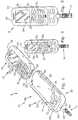
- the analytic unit portion 304 casing 305includes a generally hollow interior 338, a portion of which defines a wand storage compartment 340. As is shown in FIG. 17 , a plurality of wands 14 can be stored in the wand storage compartment 340, to be ready for use when the user so desires.
- An objective 342that includes a light output aperture 344, a light source 346 and a test strip holder 348 is disposed within the hollow interior 338.
- the light output aperture 344is positioned to be in an opposed relationship to the lens 320, so that the axis of the light output aperture 344 is colinear with the axis of the lens 320 of the digital camera within the phone 302 when the device 300 is in its closed position.
- the devicealso includes a test strip holder 348 which positions a test strip (e.g. 84) properly in the light path LP when a test wand 14 containing a test strip is inserted into the test wand receiving port 350 that is formed on a side surface of the meter portion case 304.
- the light source 346which may be an LED, shines the light upwardly through a test strip held within the test strip holder 348. This projects the image of the color formed by the analyte reaction products on the strip through the light output aperture 344, through lens 320, and onto the photo receptor 322 of the digital camera contained within the phone 302.
- This informationis then processed by the phone's circuitry and software, into information that ultimately takes the form of information relating to the existence or quantity of the analyte of interest.
- This informationis displayed on the LCD screen 310 of the phone portion 302.
- the information, along with the image,can also be saved as a file which can then be sent, as an e-mail or "test message" to another device, such as a computer used by a healthcare provider.
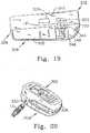
- an analyte testing device 400is shown in FIGS. 21-23 .
- the testing device 400includes a phone portion 402 and an analytic unit portion 404.
- the phone portion 402is coupled to the casing 405 of the analytic unit portion 404.
- the phone portion 402is generally similar to the mobile phones discussed above, as it includes a front surface 407 having an LCD display 410 thereon.
- the phone 402also includes a plurality of number buttons 412 and one or more function buttons 414, which serve the same purposes as in the embodiments discussed above.
- the phone portion 402also includes a rear surface 416. Similar to phone portion 302, phone portion 402 includes a camera lens 420 that is contained on the rear surface 416.
- the camera lens 420is of a type similar to those existing currently on camera containing mobile phones.
- the lens 420 and built-in digital camera contained within the phone 402are used on currently existing phones to enable the phone owner to use the cell phone user to take photographs of friends, and whatever else she may desire.
- the lens 420 and camera contained within the phone 402are also usable by a body fluid test system for taking a "picture" of the analyte-containing test strip 421, to measure one or more analytes of interest that have been tested on the test strip.
- device 400includes an optical unit 422, that includes a test positioner 424, that places the test strip 421 in a position that is out of the normal optical path.
- the normal optical path of a lensis the area directly in front of a lens.
- the optical unit 422includes an optical path diverter 426 for diverting the light path 436 to test strip 421.
- the optical path diverter 426includes a first mirror 428 disposed at a 45° angle to the light path for reflecting light at a 90° angle, from a generally "vertically" directed path (as shown in FIG. 23 ) to a "horizontally” directed path, that enables the light path to pass through the camera lens 420.
- the optical path diverter 426includes a first lens, for focusing the light path and the image shown therethrough.
- the optical unit 422 of the analytic unit 404includes a light source 434, such as an LED, that emits the light along a light path 436.
- the lightpasses through the test strip 421 that is held in the test strip positioner 424.
- Light emerging from the test strip 421 (that is passed therethrough)passes through a lens 430, where it is focused.
- the light path 436continues to extend to reflecting mirror 428, where the light path is reflected at a 90 degree angle, so that the light can pass through the lens 420 of the camera.
- Light that passes through the lens 420is captured by the CCD chip 440 of the digital camera. The image so captured is then conducted to a processor 442.
- the processor 442includes the image processing software, for processing the image. Additionally, the software is capable of processing the image captured by the CCD chip 440, to provide a quantitative analysis of the analyte contained on the analyte receiving portion of the test strip 421. The processor 442 can then transfer the data to the transmitter portion 446 of the cell phone, which itself includes software that permits the image and the quantitative analysis to be transmitted, if desired to a remote source, such as to another computer, another cell phone or to an appropriate storage device.
- a remote sourcesuch as to another computer, another cell phone or to an appropriate storage device.
Landscapes
- Health & Medical Sciences (AREA)
- Life Sciences & Earth Sciences (AREA)
- Engineering & Computer Science (AREA)
- Chemical & Material Sciences (AREA)
- Physics & Mathematics (AREA)
- Immunology (AREA)
- Molecular Biology (AREA)
- Biomedical Technology (AREA)
- Hematology (AREA)
- Urology & Nephrology (AREA)
- General Physics & Mathematics (AREA)
- General Health & Medical Sciences (AREA)
- Biochemistry (AREA)
- Pathology (AREA)
- Analytical Chemistry (AREA)
- Food Science & Technology (AREA)
- Medicinal Chemistry (AREA)
- Biophysics (AREA)
- Microbiology (AREA)
- Cell Biology (AREA)
- Biotechnology (AREA)
- Diabetes (AREA)
- Endocrinology (AREA)
- Human Computer Interaction (AREA)
- Chemical Kinetics & Catalysis (AREA)
- Plasma & Fusion (AREA)
- Investigating Or Analysing Biological Materials (AREA)
- Investigating Or Analysing Materials By The Use Of Chemical Reactions (AREA)
Description
- The present invention relates to methods and devices for testing analysis fluids, and more particularly to a device capable of simultaneously providing quantitative information about multiple test analytes. In a preferred embodiment, the multi-analyte test device can be coupled to or integrated with an existing processing device, such as a personal computer (PC), or a mobile processing device ("MPD"), such as a tablet PC, a mobile telephone, or a personal digital assistant.
- A. Trends in Healthcare. Traditional healthcare services have been concerned primarily with the treatment of disease. However, it is becoming increasingly recognized by medical professionals that while the treatment of disease will always be an important component of healthcare, the focus of healthcare should shift to the monitoring and maintenance of a person's health prior to and during the onset of a disease. It is believed that healthcare expenses can be reduced, and quality of life can be increased by: (1) monitoring health conditions prior to the onset of a disease, so that the disease can be treated earlier; and (2) convincing people to change their lifestyles in ways that reduce the likelihood of disease occurring.
Several medical conditions exist where the monitoring of levels of particular analytes in a person's blood stream are important. For example, the level of analytes such as cholesterol, glucose, and lactate are important parameters to monitor to gain an understanding of the person's over-all health condition, and to provide vehicles for early intervention, when appropriate, to help treat disease conditions early after their onset. - B. Glucose Monitoring and Diabetes. In the year 2000, 3.2 million people died from diabetes. A key to treating diabetes is maintaining appropriate glucose levels in the patient. Tight glucose control in a form of self-monitoring the blood glucose (SMBG) is considered to be the standard of care for diabetes management and treatment.
- C. Atherosclerosis and Cholesterol Levels. Coronary Artery Disease ("CAD") caused by atherosclerosis is the leading cause of death in the Western world, and is predicted to be the leading cause of death in the developing world before 2025. In the U.S., over 50 million people are candidates for drug and/or dietary treatment to modify the profiles of their lipids, such as their "good" and "bad" cholesterol. However, such treatments are enhanced if cholesterol levels are monitored.
- D. Sports Medicine and Blood Lactate Levels. A growing interest has developed in recent years in measuring blood lactate levels, since blood lactate serves as a marker of anaerobic glucose metabolism in over-trained muscles. Lactate levels are now routinely monitored by most professional and many serious amateur runners, bicyclists, and swimmers, along with people participating in many fitness and wellness programs.
- E. Products Available for Monitoring Glucose Levels. A wide variety of products exist currently, that are useable by the consumer to monitor glucose levels. Currently products are available from Roche Diagnostics (ACCU-CHEK(R) products); Bayer(R) (ASCENSIA-brand products); Therasense(R) (Free-Style(R) brand products); and Lifescan(R) (ONE-TOUCH(R) brand products).
Typically, these products consist of stand-alone meters that are used in connection with a blood test strip. To operate these meters, one employs a lancet device that punctures a tiny hole in a high-blood flow body part, such as a finger tip. A drop of blood is harvested from the hole, and placed onto a test strip. On the test strip, the cellular components (e.g. red and white blood cells) of the blood are separated from the plasma component. The plasma component may be reacted with one or more reagents that are embedded on this strip, to cause the reagents to undergo a chemical reaction, and form a reaction product. With many strips, the reaction product is colored. The color can be correlated to the level of glucose in the sample. The test strip is then "read" by the meter, usually by reflectance photometry. - F. Products Available for Monitoring Cholesterol Levels. Several home devices also exist for measuring blood cholesterol levels. Some of these devices are operated similarly to the blood glucose level testing devices described above. Examples of these include the Cardio Chek(R) and Cardio Chek(R) professional devices, and the Life Stream(R), Three Minute Cholesterol Monitor.
An alternative test methodology is illustrated with the CholesTrac home cholesterol test.
The CholesTrac test is a manual system that does not employ an electronic meter. Rather, the person using CholesTrac device visually compares the "color" of the reacted test analyte with a colorant-containing result chart to determine the cholesterol level. - G. Products Available for Monitoring Lactate Levels. Lactate measuring devices also exist that are similar to the blood glucose and cholesterol meter devices described above. Examples of these include the ACCU-TREND(R) Lactate and ACCUR-SPORT(R) portable analyzer, along with the Lactate Probe brand portable lactate analyzer. The devices operate similarly to the glucose and cholesterol meters, as a drop of blood is placed on a reagent containing test strip, which is then inserted into a meter.
- H. Blood Testing Devices Invented by the Applicants and Their Colleagues. The Applicants, along with their colleagues have invented several devices that can be used in blood testing. These devices include the capillary test strip to separate particulates shown in
Hans G. Kloepfer et al., U.S. Pat. No. 6,696,240 (24 Feb. 2004 ); the Consolidated Body Fluid Testing Device and Method shown inHans G. Kloepfer et al., U.S. Patent No. 2003/0109777 (12 Jun. 2003 ); and Hans G. Kloepfer et al., Method and Apparatus for Analyzing an Analysis Fluid,U.S. Published Patent Application No. 2006/0034728, published 16 Feb. 2006 . See alsoMary G. Kloepfer, U.S. Pat. No. 4,883,764 (28 Nov. 1989 ). - The Kloepfer et al., '240 patent relates to a capillary strip that is used to separate particulates from whole blood. The Kloepfer device performs the separation of particulate matter from plasma by employing a gradient of capillary force to move the cell and plasma containing blood sample from a sampling portion wherein the blood is deposited on the strip, to a reagent containing testing site. After the blood has reached the reagent containing test site, the cellular components are removed, with only the reacting plasma remaining.
- The Kloepfer et al., '777 publication discloses a device that includes all of the disposable blood testing components required to perform a blood test incorporated into a single, easy-to-manufacture unitary component that can be manufactured inexpensively enough to make single use and disposal economically viable. The Kloepfer consolidated testing device includes a unitary body that carries a disinfectant containing swab, a calibratable and moveable lancet, a blood-flow enhancement device, and a test strip.
- The Kloepfer '728 Publication discloses a meter for use in connection with the consolidated body fluid testing device (test wand) disclosed in the '777 Kloepfer Publication. In addition to disclosing an inventive meter, the Kloepfer '728 Publication also discloses improvements in the test wand that facilitate its use with the meter.
- Many of the improvements the Applicants and their colleagues have made to test strips and test wands make them more useful for performing blood tests from very small blood samples. Additionally, a transparent test strip is used with the testing wand to permit the meter to detect blood through transmittance photometry or reflectance photometry, rather than being limited to the reflectance photometric methods used with current meters.
- The meter disclosed in the Kloepfer et al., '728 Publication has many features in common with other meters, as it includes the common components of: (1) a receptacle for receiving a test strip; (2) a photometry system, including a light source and receiver for performing a photometric analysis of a reagent-reacted blood samples to quantitatively determine the amount of a particular analyte of interest; (3) a processor within the meter to process the results obtained by the photometric analysis to arrive at a quantitative value for the analyte of interest; and (4) a display for displaying the test results to the user.
- In summary, the three above-described Kloepfer references disclose an improved test strip and metering system that is believed by the Applicants to be more convenient to use than known systems, and that is capable of being used with smaller samples than known devices. Nonetheless, room for improvement still exists.
- For example, improvements can be made to the meter. Currently, most meters employed for measuring blood analytes are single analyte meters that are useful only for performing the particular test for which they are designed. Current meters could be improved by providing a single meter that is capable of performing a test simultaneously on a variety of analytes. A particularly welcome improvement would be to provide a test strip and metering system that was capable of performing these tests from a single blood sample.
- One short coming of current meters is that since the single analyte meters are "stand alone" meters, they require their own processing circuitry and/or software to perform many of their functions. Therefore, an improvement to this current situation would be to provide a meter that is capable of utilizing the processing capability of a device, such as a mobile phone, that most potential users already possess, and that contains the processing capability for performing many of the processing tasks currently performed by the meter, to thereby enable the user to reduce the number of devices that he must carry with him. Additionally, adding the meter components to the mobile device should be less expensive than the cost of manufacturing two separate devices.
- Another area for potential improvement is to provide the meters with the ability to communicate results to others, to a health provider, or to the user's own computer for later retrieval and storage.
EP1283023 A1 provides for a recording medium that generates a current in accordance with blood glucose level and provides for a bi-directional service between a portable terminal and a server.WO2000046598 A1 provides for a system for collecting and automatically testing a fluid specimen, where the system includes a cup and a cap that are received by a complementary keyed receptacle.- It is an object of the present invention to provide an improved blood testing system, that incorporates one or several of the improvements discussed above.
- This object is achieved by an analyte testing device of claim 1.
- In accordance with the present invention, an analyte testing device is provided in accordance with the feature combination of claim 1.
- Processing software is provided for performing a quantitative analysis of at least one analyte from the captured image, and providing an output of the results of the quantitative analysis.
- Preferably, transmission software is also provided for transmitting at least one of the captured images and quantitative analysis to the remote receiver.
- In a preferred embodiment of the present invention, the analyte containing test strip includes an analyte receiving portion upon which an analyte resides that has undergone a separation and a reaction with a reagent. The camera captures an image of the analyte receiving portion. The analyte receiving portion can include a first analyte receiving portion containing a first analyte having undergone a first reaction with a first reagent, and a second analyte receiving portion containing a second analyte having undergone a second reaction with a second reagent. The camera is positioned to capture an image of the each of the first and second analyte portions, and the software within the mobile processing device is capable of performing a quantitative analysis on each of the first and second analytes.
- In accordance with the invention, the casing is movably coupled to the mobile processing device between a testing position and a non-testing position. In the testing position, the camera lens is aligned with a test strip portion to permit the camera to capture an image of the test strip.
- In the non-testing position, the camera lens can capture an image without interference from the casing, but during which time, the casing remains coupled to the mobile processing device. In the most preferred embodiment, the mobile processing device comprises a mobile communications device, such as a cell phone; and the casing is hingedly coupled to the mobile communications device to move between the testing and non-testing position. Additionally, the casing can include a cavity for storing a plurality of test strips therein.
- The analyte testing device can either take the form of an external device that includes a plug for being coupled to a data port of the mobile processing device; or alternately, can be an internal device that is encased within the housing of the mobile communication device, and that is "hard wired" to the processor of the PD.
- Preferably, the device includes a test strip port for receiving a test strip on which the analyte of interest is contained. A light emitting device is provided for either illuminating the test field on which the analyte is contained, or alternately, for projecting light onto the test field. A miniaturized, digital camera, having a lens and image sensors is provided for either receiving the transmitted light, or alternately photographing the illuminated, analyte-containing test field. The digital camera can either comprise a "still" or motion picture type camera. A motion picture type "video" camera would have the advantage of permitting the user to evaluate the process of the reaction and the kinetics of the test procedure.
- In a preferred embodiment, the digital information received by the miniaturized digital camera is then directed to a processor for processing. The processor can comprise a processing unit contained within the analyte testing device. Alternately, the processor of the mobile processing device can be employed to process the information. The mobile processing device's display is then employed to display an output from the processor in a human readable form, so that the user may read the information contained on the display to obtain a measurement of the analyte of interest.
- The test strip can be designed to permit the measurement of a plurality of analytes simultaneously. Illustratively, a first reagent can be provided for enabling the user to determine cholesterol level; a second reagent provided for enabling the user to determine blood glucose levels; and a third reagent provided to enable the user to determine blood lactate levels.
- The test strip and digital camera can be designed to enable the miniaturized digital camera to receive photometric information about each of the plurality of reagents discreetly, so that the output of the digital camera can provide discreet information to the processor about each of the analytes of interest, thus enabling the processor to provide discreet measurements for each of the three analytes without interference from the presence of the other analytes on the test strip.
- One feature of the present invention is that the test strip can be designed to employ a plurality of test strip fields where each test strip field contains a reagent that is capable of reacting with a different analyte of interest to provide a colorimetric reaction product, whose color and intensity can be correlated with the quantity of the analyte in the test fluid. Preferably, these plurality of test fields and test results can be obtained through the application of a single "micro" fluid sample, of about one to two microlitres placed on a single test strip.
- This feature has the advantage of enabling the user to employ a test strip to test for a variety of analytes.
- This multiple test field approach has several advantages. One advantage is that the user can test for a plurality of analytes using a single test strip and a single meter. To Applicants' knowledge, consumer-useable blood testing devices currently in use are single analyte devices, that are capable of testing only for a single analyte. As such, if the user wishes to test for three analytes, he must purchase three separate test strips, and three separate meters.
- Another important advantage resides in the ability of the user to test for these plurality of samples by using only a very small blood sample. One draw back to patients who are performing self tests is the need to obtain blood samples. To obtain a blood sample, a user is required to pierce a body part, such as a fingertip with a lancet. The blood that bleeds from the tiny puncture hole is then placed onto a test strip. With the current invention, the user need only make one stick in one tissue site, and only obtain one blood sample, to test for multiple analytes, thus reducing the potential number of times the user must stick himself.
- In accordance with the invention, the testing device is coupled to a mobile communications device. This feature has the advantage of reducing the number of devices that a user must purchase and carry around with him.
- At the time of the writing of this application, mobile processing devices have become ubiquitous. Mobile processing devices can comprise a wide variety of currently known products such as PDAs, cell phones, MP3 players, lap top computers and the like.
- Cell phones are especially ubiquitous. A large plurality of the adult population in developed countries carry cell phones. Although small in size, cell phones contain a large amount of processing capability. Some cell phones, such as the Palm Treo 600 and
Treo 300 mobile phones contain a very large amount of processing capability, as the Treo models are personal digital assistants that include mobile telephone capabilities. With the large amount of processing capacity available in a device that is already carried by most people, it seems somewhat wasteful to purchase a separate meter that contains its own processing system. - To reduce this duplication, the device of the present invention employs the processing capability of the cell phone (or other mobile processing device). By making the testing device coupleable to a mobile phone, the user can carry around only a single device (his mobile phone), rather than two or more devices, such as a mobile phone and testing meter. Additionally, by obviating the need for separate processing hardware and software for the meter (as the phone's processing hardware and software can be used), the meter can likely be manufactured less expensively, thus reducing the cost to the end user.
- A further advantage provided by the use of a mobile processing device that includes a communication capability is that it permits the user to communicate his test results with others. For example, the user can use the mobile phone to transmit his test results to a healthcare provider who can then monitor the patient's test results, and thereby monitor the patient's health. Additionally, the results can be transmitted from the mobile phone to a user's computer, to enable the user to employ his computer's large memory capability to archive his test results. The transmission can take the form of a text message, or graphic display, and can be forwarded as an e-mail type message.
- A further feature of the present invention is that the test device is designed to use reagents that produce calorimetric reactions. This use of calorimetric reagents has several advantages. One advantage is that the colorimetric reagents, when used on a clear test field, permit the use of transmittance photometry to measure the color produced in the reaction product to thereby quantify the amount of the analyte of interest in the test samples.
- Another advantage obtained through the use of a colorimetric measurement is that it permits the user to visually see the results, thereby permitting the user to make a visual reliability check on the accuracy of the device.
- A further advantage obtained by the colorimetric reaction is that it provides a color-containing image of which a photograph can be taken by a miniaturized digital camera contained within the device. This digital image can be used for archival purposes. Alternately, the digital information contained from the digital "photograph" can be employed as the information that is processed by the processor of the mobile processing device to obtain the quantitative analysis of the analyte of interest.
- These and other features and advantages of the present invention will become apparent to those skilled in the art upon a review of the drawings and detailed description of the preferred embodiment of the present invention provided herein that represent the best mode of practicing the invention perceived presently by the Applicants.
FIG. 1 is a perspective, exploded view of a body fluid testing system not within the scope of the present invention;FIG. 2 is a top view of the system;FIG. 3 is an enlarged, top view of the system;FIG. 4 is an enlarged, perspective view, partly broken away, of a test strip containing test wandFIG. 5 is a top view of the system showing a plurality of test wands coupled thereto;FIG. 6 is a top, greatly enlarged schematic view of a test strip useable with a test wandFIG. 7 is a schematic view of the test strip, light source, and digital camera components;FIG. 8 is a perspective view, with the case of the meter component testing system partly broken away;FIG. 9 is a perspective view, with a case of the meter component testing system removed;FIG. 10 is an enlarged, somewhat schematic top view, showing a test wand inserted into a strip receiver;FIG. 11 is another top view, partly broken awayFIG. 12 is a perspective view of an another device not within the scope of the present invention;FIG. 13 is a top exploded view showing the device useable with an MPD, and a test wand;FIG. 14 is a perspective view showing a device with a two-part clamshell like case not within the scope of the present invention,FIG. 15-20 show various perspective views of a device not within the scope of the present invention.FIG. 21 is a front perspective view of an embodiment of the present invention that employs an optical path diameter that permits an image of a test strip to be captured, even though the test strip positioner positions the test strip out of the normal optical path of the camera lens;FIG. 22 is a front perspective view of the embodiment ofFIG. 21 wherein the camera face is "closed" to hide the number buttons; andFIG. 23 is a side, schematic view of the alternate embodiment shown inFIG. 21 .- A body
fluid testing system 8 is shown in the figures, as being comprised of three primary components. These three components include a body fluid testinganalytic unit 10, that is capable of being operatively coupled to mobile processing device, and preferably a mobile communications device, here shown as amobile telephone 12. The third primary component is a test strip containingtest wand 14 that is similar or identical to the ones disclosed in the Kloepfer et al., '777 Publication, and/or the Kloepfer et al., '728 publication, and which includes a test strip similar to the ones disclosed in the Kloepfer '240 patent. - The most common mobile processing device with which the
system 8 will likely be used are mobile communications devices such as mobile phones. Thesystem 8 will likely be used withmobile phones 12 because mobile phone currently have three attributes that contribute to-the viability of the present invention. The first attribute is that they generally have fairly robust processors that, through programming (such as by loading software into them), can be made to be capable of processing information received from theanalytic unit 10 to create a user-readable output. Some mobile phones currently in use contain a very high level of processing capability, and are currently both capable of being programmed, and performing functions far beyond the typical conversation transmission functions performed by cellular phones. For example, thePalm& TreoS 300, and 600 models comprise personal data assistants, that also include a mobile phone component. - The recently released Palm Treo 700 W has special utility as it is capable of running Microsoft(R) Windows(R) mobile applications. Devices such as the Palm Treo 600, 650 and 700 also are equipped with a significant amount of memory, e.g. 64 meg, that can be expanded drastically through the addition of a flash memory card into the already-existing socket provided for receiving same.
- Personal data assistants have many of the same functionalities as computers, possessing the ability to run programs, display information, perform calculations and the like. Additionally, other currently existing cell phones have camera capabilities, and thereby the processing capability to process digital picture information, along with the ability to transmit that digital picture information.
- The
mobile phone 12 includes ahousing 18 that encases the electronic components of themobile phone 12. Thehousing 18 includes afront surface 20, afirst side surface 22, andsecond side surface 24, a first (top)end surface 26, and a second (bottom)end surface 28. Thefront surface 20 includes a plurality (usually twelve) ofnumber buttons 32, that the user presses for dialing a phone number, and a plurality offunction buttons 34 that the user may push in some predetermined sequence to access and perform the various functions of which thephone 12 is capable of performing. A main function button that can be designed to be anavigator button 36 is disposed between thefunction buttons 34 of the device shown in the drawing. - An LCD display 30 is also disposed on the
front surface 20, and is capable of displaying a significant amount of information. In mobile phone/PDAs, the LCD displays can be quite large (e.g. four square inches), and be capable of displaying a significant amount of information. Optionally, theLCD display 38 may comprise a touch screen that aids the user in navigating through menus and performing the various functions of which thephone 12 is capable. Although not necessary with the present device, a touch-screen type LCD 38 is preferably used, as it facilitates the operation of the device by the user. - A
data transfer port 42 is disposed on thebottom end surface 28. A wide variety of data transfer ports exist for use in connection with current PDs. Many of the ports are used not only for transferring data between the device and another device (such as a computer), but are also used to carry voltage and current into the device to recharge the batteries of themobile phone 12. - The testing device/
analytic unit 10 includes acase 46, that includes acradle portion 48 and a component-containinglower portion 50. Thecradle portion 48 is designed to grip and hold themobile phone 12 to couple theanalytic unit 10 to thephone 12. Thecasing 46 is preferably made from a plastic material and may be constructed as a "clamshell" having two halves connected with a living hinge. The edges of the casing can then be either permanently bonded together through sonic welding (after the components are inserted), or can be held together with a removable fastener such as screws, so that the user may separate the two casing halves, if necessary, to perform servicing of the electronic components contained therein. - The
cradle portion 48 includes arear support member 52 that is placeable adjacent to the rear surface of the housing of thephone 12; a firstside support member 54 that is provided for gripping the first side surface 22of thehousing 18 of thephone 12; and asecond side support 56 for gripping thesecond side surface 28 of thehousing 18 of thephone 12. Each of the first and second side supports 54, 56 can include a longitudinally extendingclip rail 58. As is best shown inFIG. 3 ,clip rail 58 is provided for enabling a corresponding clip on thetest wands 14A-14D to grip theclip rail 58. Through this ability of thetest wand 14 to grip on to theclip rail 58, the user can carry around a plurality oftest wands 14A-14D on his mobile phones This ability to carry a plurality oftest wands 14A-14D is important to persons who are either traveling and must carryseveral test wands 14 with them, or those who must test their blood multiple times on a daily basis. - The
component containing portion 50 of theanalytic unit 10 includes an upper surface containing a plurality of operation buttons, includingfunction button 70, and a main ornavigator button 72. By pressing one or a combination of thefunction 70 andnavigator 72 buttons, the user can direct the operation of the device. Thecasing 46 of theanalytic unit 10 also includes a phone engagingfirst end surface 74 that is designed for engaging thebottom end surface 28 of thephone 12. An axially extendingplug 76 extends axially outwardly from the phone engagingfirst end surface 74 and is designed and configured to engage thedata port 42 of thephone 12. Thecasing 46 also includes a wand engagingsecond end surface 80 that includes a testwand receiving port 82. - Test
wand receiving port 82 is sized and configured for receiving and appropriately positioning the test strip 84 (FIG. 4 ) that is coupled to atest strip holder 86 that is formed as a part of thetest wand 14. The testwand receiving port 82 serves as a test strip positioner that is designed to receive atest strip 84 in a proper orientation, to help ensure that thetest strip 84 is inserted properly into themeter 12. Thetest strip 84 is properly oriented into theanalytic unit 10 when a major plane of thetest strip 84 is generally perpendicular to the plane of theupper surface 68 of themeter 10, so that the camera of the device can capture an image of the analyte containing portion of thetest strip 84. - As best shown in
FIG. 4 , thetest strip 84 is disposed at the end of atest wand 14, and includes an analyte receiving portion for receiving an appropriately separated body fluid that has reacted with an appropriate reagent. However, ahinge 90 hingedly couples apressure cup 88 to the same end of thetest wand 14, so that when not in use, thepressure cup 88 can cover the end of thetest strip 84 to prevent contamination or destruction of thetest strip 84. The manner in which thepressure cup 88 is used, and thetest wand 14 is constructed, is discussed in more detail in the Kloepfer '777 and '728 publications. - As is best shown in
FIGS. 8-11 , the components of themeter 12 include a printedcircuit board 100 that both serves as a base upon which other components are placed, and also as a communication platform to enable electronic communication between the various components. A strip take-upunit 102 is disposed centrally on the printedcircuit board 100, and is provided for receiving and properly orienting thetest strip 84. - The strip take-up
unit 102 includes anaxially extending passageway 104, that receives the take-uptest strip 84 and a portion of thetest strip holder 86. Theaxially extending passageway 104 is configured to have a vertical slot portion for properly orienting thetest strip 84 within thetest strip unit 102, so that thetest strip 84 will be well positioned for the passage of light therethrough, to perform the test performed by the meter. Preferably, the major plane of thetest strip 84 is disposed in a plane perpendicular to the direction of travel of the light path. - A laterally extending
passageway 108 is also provided. The laterally extendingpassageway 108 extends generally perpendicular to theaxially extending passageway 104, and intersects theaxially extending passageway 104, so that the twopassageways passageway 108 is to provide a passageway for the light waves traveling alonglight path 122, which light waves are emitted by the light source, such asLED 114, and are received by thedigital camera 124. - The light source component of the
analytic unit 10 includes lightsource control circuitry 112 that is provided for controlling the operation of thelight source 114. As discussed above, thelight source 114 preferably comprises an LED-type light. The LEDlight source 114 emits beams of light that travel through a spread glass orplate 120 disposed in the laterally extendingpassageway 104 for ensuring a uniform light distribution across thetest strip 84. - A miniaturized
digital camera 124 is provided for recording a digital image of the reagent reaction products on thetest strip 84. Thedigital camera 124 includes an objective, such aslens 126, and an image sensor for receiving the signals, along with signal processing software for processing signals into a digital picture. The image recorded by the digital camera can be a "picture", or can be signals representative of the light intensity, light wave length ("color"), or other parameter useful for measuring the concentration of the analyte of interest within the reagent reaction product on the analyte receiving portion of thetest strip 84. - Similar to most digital cameras, the
digital camera 124 of the present invention will likely employ charge-coupled devices (CCDs) for capturing the image of the test strip. A CCD is a sensor for recording images that is in digital photography and astronomy, and consists of an integrated circuit containing an array of linked, or coupled, capacitors. Under the control of an external circuit, each capacitor can transfer its electric charge to one or other of its neighbors. - Digital color cameras generally use a Bayer mask over the CCD. Each square of four pixels has one filtered red, one blue, and two green (the human eye is more sensitive to green than either red or blue). The result of this is that luminance information is collected at every pixel, but the color resolution is lower than the luminance resolution. Better color separation can be reached by three-CCD devices (3CCD) and a dichroic beam splitter prism, that splits the image into red, green and blue components. Each of the three CCDs is arranged to respond to a particular color. Some semi-professional digital video camcorders (and all professionals) use this technique.
- The
device 8 shown in the figures can operate through a transmissive mode, where the light transmitted by theLED 114 is transmitted in a straight line through the test strip to thevideo receptor 130 of thedigital camera 124. Alternately, the device can be designed to operate in a reflectance type mode, wherein the LED light source, test strips, and video receptor form an angled light path so that the video receptor (lens) captures an image of light emitted from the light source that is reflected off a surface of the test strip. - One of the important attributes of the light 114 and
camera 124 used in theanalytic unit 10, is that they provide a controlled light environment within the casing wherein a reproduceable and sufficient amount of light is shined upon thetest strip 84. By containing the light 114 andcamera 124 components within a casing, interference from outside light sources, such as lights within a room, the sun, etc., can be eliminated, thus helping to bolster the reproducibility and accuracy of the tests performed by the device. - Turning now to
FIGS. 6 and 7 , thetest strip 84 includes asubstrate member 138 having anupper surface 140, in which a sample travel path is formed. The sample travel path includes asample receiving area 142, that is sized and positioned for receiving a drop of body fluid, such as blood, from the patient. As described in more detail in the Kloepfer et al. references described above, a capillary channel 146 is provided for separating the plasma component of the blood from the cellular components such as the red and white blood cells. The cells must normally be separated from the blood in order to obtain an appropriate calorimetric reaction that does not contain interfering colors caused with the colored components of the blood, such as the red and white blood cells. - The capillary channel includes a
testing area 150 which comprises ananalyte receiving portion 150 upon which reagent strips 154, 156, 158 are placed, and anexcess collection area 148 that is disposed downstream of theanalyte receiving portion 150 for collecting excess fluids, to ensure that only a proper quantity of fluid remains in theanalyte receiving portion 150. As alluded to in this description, a sample of blood is placed in asample collection area 142, and flows in a direction designated by arrow BF, through thecapillary portion 144, where the cellular components are retained. In the testing area, the plasma fluid reacts with the reagents placed onreagent strips - The first 154, second 156 and third 158 reagent strips each may contain a different reagent for testing a different analyte of interest. For example, the
first reagent 154 can be a reagent designed to elicit a quantitative colorimetric reaction from a first analyte of interest, such as blood glucose level. Similarly, thesecond reagent 156 can be a reagent designed to detect the presence of a second analyte of interest, such as blood cholesterol, and the third reagent can be designed for detecting a third analyte of interest such as blood lactate levels. - Alternately, each of the first, second and third reagent strips 154, 156, 158 respectively, can be the same reagent for determining the same analyte of interest. In this case, three reagent strips may be used to provide back ups to each other, or else permit the user to average the values determined by the colorimetric reaction produced by each of the three reagents.
- Although the
test strip 84 is shown as having a first, second and third 154, 156, 158 reagent strips, it will also be appreciated that more than three or less than three reagent strips can be used, to test a greater or lesser number of analytes of interest. Surprisingly, the Applicants have found that the width of the reagent strip can be reduced to about 1 mm., while still providing a sufficient area so that the digital camera or other sensor will be able to pick up enough appropriate information to provide reliable test strips. - It should also be noted that although the reagents are currently shown as being "reagent strips" 154, 156, 158, the shape and dimension of the reagent placements can vary. For example, the reagents' "strips" can be replaced by a plurality of reagent "dots".
- An alternate
blood testing system 200 is shown inFIGS. 12 and 13 .Testing system 200 is virtually identical totesting system 10. The main difference between the two is that theblood testing device 204, has a different shaped casing, and different shapeddata port plug 210, to better fit the particular model ofmobile phone 202 shown in the drawings. It will also be noted that the casing of thetesting device 204 does not include the side rail structures or back support structure of the casing shown inFIGS. 1-11 . - The blood testing device (analytic unit) 204 includes a
top surface 208, that may or may not include a series of function buttons. The function buttons can be eliminated if the device is designed so that the act of connecting theplug 210 to thedata receiving port 212 activates thephone 202 to recognize theanalytic unit 204, and to display operational information on the LCD screen. In such case, the operation of theanalytic unit 204 is controlled by thenumber button 216 andfunction buttons 218 of the cell phone. Theblood test device 202 also includes awand receiving port 214 to receive thetest strip 84 oftest wand 14. - An example of a clamshell-type
blood testing device 300 is shown inFIG. 14-20 . Thetesting device 300 includes aphone portion 302 and ananalytic unit portion 304. Thephone portion 302 is hingedly coupled to thecasing 305 of theanalytic unit portion 304 by ahinge 306. - The
phone portion 302 is generally similar to the mobile phones discussed above, as it includes afront surface 307 having anLCD display 310 thereon. Thephone 302 also includes a plurality ofnumber buttons 312 and one ormore function buttons 314, which serve the same purposes as in the embodiments discussed above. Thephone portion 302 also includes arear surface 316. One element contained onphone portion 302, which is not described with respect to the phones discussed above is acamera lens 320 that is contained on therear surface 316. Thecamera lens 320 is of a type similar to those existing currently on camera containing mobile phones. Thelens 320 and built-in digital camera contained within thephone 302 are used on currently existing phones to enable the phone owner to use the cell phone user to take photographs of friends, and whatever else she may desire. - One of the unique features of the
device 300 shown inFIGS. 14-20 , is that thelens 320 and camera contained within thephone 302 are also usable by a body fluid test system for taking a "picture" of the analyte-containing test strip, to measure one or more analytes of interest that have been tested on the test strip. - As is best shown in
FIG. 19 , thelens 320 focuses light onto aphoto receptor 322 contained within the interior of thephone portion 302. Thephoto receptor 322 is coupled toimage processing circuitry 324 that is capable of processing the digital image received by thephoto receptor 322. As is discussed in more detail above, the "processing" component of thephone 302 can comprise separate circuitry, or rely on the camera's or phone's already existing circuitry. Additionally, the processor of thephone 302 can include software that is runs on the processor of thephone 302 that can be specifically adapted for performing the analyte test of the present invention. - As best shown in
FIGS. 17 and 18 , thephone portion case 302 includes alip 332 that is capable of engaging alip 330 of the analyticunit portion case 304, so that the two portions can be placed a "closed" or "testing" position, as is shown inFIGS. 14 ,19, and 20 . A latch member (not shown) and release button (not shown) can be employed to respectively latch the twoportions portions phone portion 302 andanalytic unit portion 304 can be moved abouthinge 306 into an "open" or "non-testing" position, similar to that shown inFIGS. 16, 17 and 18 . When the casing is in the non-testing or open position, thecamera lens 320 becomes unobstructed by theanalytic unit portion 304casing 305, thus enabling the camera to take a picture without interference from the casing. In such a position, for example, a picture of a friend can be taken without the casing becoming a part of the picture. - The
analytic unit portion 304casing 305 includes a generally hollow interior 338, a portion of which defines awand storage compartment 340. As is shown inFIG. 17 , a plurality ofwands 14 can be stored in thewand storage compartment 340, to be ready for use when the user so desires. - An objective 342 that includes a
light output aperture 344, alight source 346 and atest strip holder 348 is disposed within the hollow interior 338. Thelight output aperture 344 is positioned to be in an opposed relationship to thelens 320, so that the axis of thelight output aperture 344 is colinear with the axis of thelens 320 of the digital camera within thephone 302 when thedevice 300 is in its closed position. - The device also includes a
test strip holder 348 which positions a test strip (e.g. 84) properly in the light path LP when atest wand 14 containing a test strip is inserted into the testwand receiving port 350 that is formed on a side surface of themeter portion case 304. As is best shown inFIG. 19 , thelight source 346, which may be an LED, shines the light upwardly through a test strip held within thetest strip holder 348. This projects the image of the color formed by the analyte reaction products on the strip through thelight output aperture 344, throughlens 320, and onto thephoto receptor 322 of the digital camera contained within thephone 302. This information is then processed by the phone's circuitry and software, into information that ultimately takes the form of information relating to the existence or quantity of the analyte of interest. This information is displayed on theLCD screen 310 of thephone portion 302. The information, along with the image, can also be saved as a file which can then be sent, as an e-mail or "test message" to another device, such as a computer used by a healthcare provider. - In accordance with the invention an
analyte testing device 400 is shown inFIGS. 21-23 . Thetesting device 400 includes aphone portion 402 and ananalytic unit portion 404. Thephone portion 402 is coupled to thecasing 405 of theanalytic unit portion 404. - The
phone portion 402 is generally similar to the mobile phones discussed above, as it includes afront surface 407 having anLCD display 410 thereon. Thephone 402 also includes a plurality ofnumber buttons 412 and one ormore function buttons 414, which serve the same purposes as in the embodiments discussed above. Thephone portion 402 also includes arear surface 416. Similar tophone portion 302,phone portion 402 includes acamera lens 420 that is contained on therear surface 416. Thecamera lens 420 is of a type similar to those existing currently on camera containing mobile phones. Thelens 420 and built-in digital camera contained within thephone 402 are used on currently existing phones to enable the phone owner to use the cell phone user to take photographs of friends, and whatever else she may desire. - Similar also to
phone 302, thelens 420 and camera contained within thephone 402 are also usable by a body fluid test system for taking a "picture" of the analyte-containingtest strip 421, to measure one or more analytes of interest that have been tested on the test strip. - Another difference between
device 400 anddevice 300, is thatdevice 400 includes anoptical unit 422, that includes atest positioner 424, that places thetest strip 421 in a position that is out of the normal optical path. As will be appreciated, the normal optical path of a lens is the area directly in front of a lens. Theoptical unit 422 includes an optical path diverter 426 for diverting thelight path 436 totest strip 421. The optical path diverter 426 includes afirst mirror 428 disposed at a 45° angle to the light path for reflecting light at a 90° angle, from a generally "vertically" directed path (as shown inFIG. 23 ) to a "horizontally" directed path, that enables the light path to pass through thecamera lens 420. Additionally, the optical path diverter 426 includes a first lens, for focusing the light path and the image shown therethrough. - The
optical unit 422 of theanalytic unit 404 includes alight source 434, such as an LED, that emits the light along alight path 436. The light passes through thetest strip 421 that is held in thetest strip positioner 424. Light emerging from the test strip 421 (that is passed therethrough) passes through alens 430, where it is focused. Thelight path 436 continues to extend to reflectingmirror 428, where the light path is reflected at a 90 degree angle, so that the light can pass through thelens 420 of the camera. Light that passes through thelens 420 is captured by theCCD chip 440 of the digital camera. The image so captured is then conducted to aprocessor 442. - The
processor 442 includes the image processing software, for processing the image. Additionally, the software is capable of processing the image captured by theCCD chip 440, to provide a quantitative analysis of the analyte contained on the analyte receiving portion of thetest strip 421. Theprocessor 442 can then transfer the data to thetransmitter portion 446 of the cell phone, which itself includes software that permits the image and the quantitative analysis to be transmitted, if desired to a remote source, such as to another computer, another cell phone or to an appropriate storage device.
Claims (23)
- An analyte testing device (400) with a mobile processing device (402) having a camera (440) with a camera lens (420), and a processor (442) adapted to process an image captured by the camera (440), the analyte testing device comprising:a casing (405);an optical unit (422) that includes a test strip positioner (424) adapted to position an analyte containing test strip (421) in a position, wherein the camera lens (420) can capture an image of the analyte containing test strip (421) that is illuminated by a light source (434) provided in the optical unit (422) and adapted to direct light within the casing (405) to illuminate the analyte containing test strip (421) to facilitate the capture of the image of the test strip (421); andsaid processor (442) comprising software contained within the mobile processing device (402) and adapted to perform a quantitative analysis of at least one analyte from the captured image, and adapted to provide an output of the results of the quantitative analysis,wherein the mobile processing device (402) is movably coupled to the casing (405) of the analyte testing device (400) between a testing position and a non-testing position, andwherein the mobile processing device (402) comprises a mobile communications device (402).
- The analyte testing device of Claim 1, wherein the analyte containing test strip includes a first analyte receiving portion (154) containing a first analyte comprising a first body fluid fraction that has undergone a first reaction, and a second analyte receiving portion (156) containing a second analyte comprising a second body fluid fraction that has undergone a second reaction with a second reagent.
- The analyte testing device of Claim 1, further comprising transmission software loadable into the mobile communications device (402) for transmitting at least one of the captured images and the quantitative analysis to a remote receiver.
- The analyte testing device of Claim 3, wherein the transmission software is capable of transmitting both the captured image and the output of the results of the quantitative analysis to the remote receiver.
- The analyte testing device of Claim 1, wherein the casing (405) is capable of enclosing the camera lens and the light source to provide a controlled light environment within the casing.
- The analyte testing device of Claim 5, wherein the light source (112), the test strip (140) and the camera lens (166) are positionable to define a linear light path, wherein the light source shines its light through the test strip and into the camera lens.
- The analyte testing device of Claim 5, wherein the light source (114), the test strip (140) and the camera lens (166) are positionable to define an angled light path, wherein the camera lens captures an image of light emitted from the light source that is reflected off of a surface of the test strip (140).
- The analyte testing device of Claim 1, wherein the analyte containing test strip (84) includes an analyte receiving portion (150) upon which an analyte resides that comprises a body fluid that has undergone a separation and a reaction with a reagent, wherein the camera (130) captures an image of the analyte receiving portion.
- The analyte testing device of Claim 8, wherein the analyte receiving portion (150) includes a first analyte receiving portion (154) containing a first analyte comprising a first body fluid fraction that has undergone a first reaction, and a second analyte receiving portion (156) containing a second analyte comprising a second body fluid fraction that has undergone a second reaction with a second reagent.
- The analyte testing device of Claim 9, wherein the analyte receiving portion (150) further includes a third analyte receiving portion (158) containing a third analyte comprising a third body fluid fraction that has undergone a third reaction with a third reagent.
- The analyte testing device of Claim 10, wherein the first analyte comprises a body fluid and reagent useful for determining blood glucose levels, the second analyte comprises a body fluid and reagent useful for determining blood cholesterol levels, and the third analyte comprises a body fluid and reagent useful for determining blood lactate levels.
- The analyte testing device of Claim 1, wherein the casing (305) includes a cavity (340) for storing a plurality of test strips (14) therein.
- The analyte testing device of Claim 1, wherein the casing (305) is movably coupled to the mobile processing device (302) to permit the camera lens (320) of the camera to capture images without interference from the casing (305).
- The analyte testing device of Claim 13, wherein the casing (305) is movable between a testing position, wherein the camera lens (320) is aligned with the test strip positioner (150) to permit the camera to capture an image of the test strip (14); and a non-testing position, wherein the camera lens (320) can capture an image without interference from the casing (305), but during which time the casing remains coupled to the mobile communications device.
- The analyte testing device of Claim 14, wherein the casing (305) includes a cavity (340) for storing a plurality of test strips (14) therein.
- The analyte testing device of Claim 1, wherein the casing (305) is hingedly coupled to the mobile communications device (302) and is movable between a testing position, wherein the camera lens (320) is aligned with the test strip positioner (349) to permit the camera to capture an image of the test strip (14), and a non-testing position, wherein the camera lens can capture an image without interference from the casing (305), but during which time the casing (305) remains coupled to the mobile communications device (302).
- The analyte testing device of claim 1, wherein the casing (305) includes a cavity (340) for storing a plurality of test strips (14) therein, and wherein the test strip (14) includes an analyte receiving portion (150), upon which an analyte resides that includes a body fluid that has undergone a separation and a reaction with a reagent, wherein the camera (320) captures an image of the analyte receiving portion (150).
- The analyte testing device of Claim 17, wherein the analyte receiving portion (150) includes a first analyte receiving portion (154) containing a first body fluid fraction that has undergone a separation and a reaction with a first reagent, and a second analyte receiving portion (156) that has undergone a separation and a reaction with a second reagent, wherein the camera (124) captures an image of the first (154) and second (156) analyte receiving portions; and wherein the software contained within the mobile processing device (302) performs a quantitative analysis of each of the first and second separated and reacted body fluid fractions.
- The analyte testing device of Claim 1, wherein the casing is formed as a part of the mobile processing device.
- The analyte testing device of Claim 1, wherein the camera lens (166) is coupled to the casing, further comprising a data output connector (76) for coupling the camera lens (166) to a part of the mobile processing device (10) for transferring data from the camera lens to the mobile processing device.
- The analyte testing device of Claim 19, wherein the casing includes a phone receiving portion (48) for permitting the casing (46) to be detachably coupled to the mobile processing device (10).
- The analyte testing device of Claim 1, wherein the test strip positioner (424) positions the test strip (421) in a position out of the optical path of the camera lens (420), and wherein the casing (405) includes an optical path diverter (426) between the camera lens (420) and the test strip (421) for permitting the camera (440) to capture an image of the analyte containing test strip (421).
- The analyte testing device of Claim 1, wherein the optical path diverter (426) comprises at least one mirror reflector (428) for reflecting an image of the analyte containing test strip (421) into the camera lens (420).
Priority Applications (1)
| Application Number | Priority Date | Filing Date | Title |
|---|---|---|---|
| PL15200495TPL3026874T3 (en) | 2005-04-01 | 2006-03-30 | Body fluid testing component for analyte detection |
Applications Claiming Priority (3)
| Application Number | Priority Date | Filing Date | Title |
|---|---|---|---|
| US66724005P | 2005-04-01 | 2005-04-01 | |
| EP06748840.3AEP1866637B1 (en) | 2005-04-01 | 2006-03-30 | Body fluid testing component for analyte detection |
| PCT/US2006/011375WO2006107666A2 (en) | 2005-04-01 | 2006-03-30 | Body fluid testing component for analyte detection |
Related Parent Applications (2)
| Application Number | Title | Priority Date | Filing Date |
|---|---|---|---|
| EP06748840.3ADivisionEP1866637B1 (en) | 2005-04-01 | 2006-03-30 | Body fluid testing component for analyte detection |
| EP06748840.3ADivision-IntoEP1866637B1 (en) | 2005-04-01 | 2006-03-30 | Body fluid testing component for analyte detection |
Publications (2)
| Publication Number | Publication Date |
|---|---|
| EP3026874A1 EP3026874A1 (en) | 2016-06-01 |
| EP3026874B1true EP3026874B1 (en) | 2019-11-06 |
Family
ID=37073950
Family Applications (2)
| Application Number | Title | Priority Date | Filing Date |
|---|---|---|---|
| EP15200495.8AActiveEP3026874B1 (en) | 2005-04-01 | 2006-03-30 | Body fluid testing component for analyte detection |
| EP06748840.3ANot-in-forceEP1866637B1 (en) | 2005-04-01 | 2006-03-30 | Body fluid testing component for analyte detection |
Family Applications After (1)
| Application Number | Title | Priority Date | Filing Date |
|---|---|---|---|
| EP06748840.3ANot-in-forceEP1866637B1 (en) | 2005-04-01 | 2006-03-30 | Body fluid testing component for analyte detection |
Country Status (5)
| Country | Link |
|---|---|
| US (2) | US8145431B2 (en) |
| EP (2) | EP3026874B1 (en) |
| CA (1) | CA2601720C (en) |
| PL (2) | PL1866637T3 (en) |
| WO (1) | WO2006107666A2 (en) |
Families Citing this family (286)
| Publication number | Priority date | Publication date | Assignee | Title |
|---|---|---|---|---|
| US6036924A (en) | 1997-12-04 | 2000-03-14 | Hewlett-Packard Company | Cassette of lancet cartridges for sampling blood |
| US6391005B1 (en) | 1998-03-30 | 2002-05-21 | Agilent Technologies, Inc. | Apparatus and method for penetration with shaft having a sensor for sensing penetration depth |
| US8641644B2 (en) | 2000-11-21 | 2014-02-04 | Sanofi-Aventis Deutschland Gmbh | Blood testing apparatus having a rotatable cartridge with multiple lancing elements and testing means |
| DE10057832C1 (en) | 2000-11-21 | 2002-02-21 | Hartmann Paul Ag | Blood analysis device has syringe mounted in casing, annular mounting carrying needles mounted behind test strip and being swiveled so that needle can be pushed through strip and aperture in casing to take blood sample |
| EP1395185B1 (en) | 2001-06-12 | 2010-10-27 | Pelikan Technologies Inc. | Electric lancet actuator |
| US7041068B2 (en) | 2001-06-12 | 2006-05-09 | Pelikan Technologies, Inc. | Sampling module device and method |
| JP4209767B2 (en) | 2001-06-12 | 2009-01-14 | ペリカン テクノロジーズ インコーポレイテッド | Self-optimized cutting instrument with adaptive means for temporary changes in skin properties |
| US9795747B2 (en) | 2010-06-02 | 2017-10-24 | Sanofi-Aventis Deutschland Gmbh | Methods and apparatus for lancet actuation |
| JP4272051B2 (en) | 2001-06-12 | 2009-06-03 | ペリカン テクノロジーズ インコーポレイテッド | Blood sampling apparatus and method |
| AU2002344825A1 (en) | 2001-06-12 | 2002-12-23 | Pelikan Technologies, Inc. | Method and apparatus for improving success rate of blood yield from a fingerstick |
| US8337419B2 (en) | 2002-04-19 | 2012-12-25 | Sanofi-Aventis Deutschland Gmbh | Tissue penetration device |
| US9427532B2 (en) | 2001-06-12 | 2016-08-30 | Sanofi-Aventis Deutschland Gmbh | Tissue penetration device |
| WO2002101359A2 (en) | 2001-06-12 | 2002-12-19 | Pelikan Technologies, Inc. | Integrated blood sampling analysis system with multi-use sampling module |
| US7981056B2 (en) | 2002-04-19 | 2011-07-19 | Pelikan Technologies, Inc. | Methods and apparatus for lancet actuation |
| US9226699B2 (en) | 2002-04-19 | 2016-01-05 | Sanofi-Aventis Deutschland Gmbh | Body fluid sampling module with a continuous compression tissue interface surface |
| US7344507B2 (en) | 2002-04-19 | 2008-03-18 | Pelikan Technologies, Inc. | Method and apparatus for lancet actuation |
| US7749174B2 (en) | 2001-06-12 | 2010-07-06 | Pelikan Technologies, Inc. | Method and apparatus for lancet launching device intergrated onto a blood-sampling cartridge |
| US7344894B2 (en) | 2001-10-16 | 2008-03-18 | Agilent Technologies, Inc. | Thermal regulation of fluidic samples within a diagnostic cartridge |
| US7892183B2 (en) | 2002-04-19 | 2011-02-22 | Pelikan Technologies, Inc. | Method and apparatus for body fluid sampling and analyte sensing |
| US7410468B2 (en) | 2002-04-19 | 2008-08-12 | Pelikan Technologies, Inc. | Method and apparatus for penetrating tissue |
| US8579831B2 (en) | 2002-04-19 | 2013-11-12 | Sanofi-Aventis Deutschland Gmbh | Method and apparatus for penetrating tissue |
| US8267870B2 (en) | 2002-04-19 | 2012-09-18 | Sanofi-Aventis Deutschland Gmbh | Method and apparatus for body fluid sampling with hybrid actuation |
| US9248267B2 (en) | 2002-04-19 | 2016-02-02 | Sanofi-Aventis Deustchland Gmbh | Tissue penetration device |
| US7674232B2 (en) | 2002-04-19 | 2010-03-09 | Pelikan Technologies, Inc. | Method and apparatus for penetrating tissue |
| US7909778B2 (en) | 2002-04-19 | 2011-03-22 | Pelikan Technologies, Inc. | Method and apparatus for penetrating tissue |
| US7291117B2 (en) | 2002-04-19 | 2007-11-06 | Pelikan Technologies, Inc. | Method and apparatus for penetrating tissue |
| US7648468B2 (en) | 2002-04-19 | 2010-01-19 | Pelikon Technologies, Inc. | Method and apparatus for penetrating tissue |
| US7901362B2 (en) | 2002-04-19 | 2011-03-08 | Pelikan Technologies, Inc. | Method and apparatus for penetrating tissue |
| US7563232B2 (en) | 2002-04-19 | 2009-07-21 | Pelikan Technologies, Inc. | Method and apparatus for penetrating tissue |
| US7374544B2 (en) | 2002-04-19 | 2008-05-20 | Pelikan Technologies, Inc. | Method and apparatus for penetrating tissue |
| US7491178B2 (en) | 2002-04-19 | 2009-02-17 | Pelikan Technologies, Inc. | Method and apparatus for penetrating tissue |
| US7717863B2 (en) | 2002-04-19 | 2010-05-18 | Pelikan Technologies, Inc. | Method and apparatus for penetrating tissue |
| US7708701B2 (en) | 2002-04-19 | 2010-05-04 | Pelikan Technologies, Inc. | Method and apparatus for a multi-use body fluid sampling device |
| US8784335B2 (en) | 2002-04-19 | 2014-07-22 | Sanofi-Aventis Deutschland Gmbh | Body fluid sampling device with a capacitive sensor |
| US7232451B2 (en) | 2002-04-19 | 2007-06-19 | Pelikan Technologies, Inc. | Method and apparatus for penetrating tissue |
| US9314194B2 (en) | 2002-04-19 | 2016-04-19 | Sanofi-Aventis Deutschland Gmbh | Tissue penetration device |
| US7524293B2 (en) | 2002-04-19 | 2009-04-28 | Pelikan Technologies, Inc. | Method and apparatus for penetrating tissue |
| US7371247B2 (en) | 2002-04-19 | 2008-05-13 | Pelikan Technologies, Inc | Method and apparatus for penetrating tissue |
| US8221334B2 (en) | 2002-04-19 | 2012-07-17 | Sanofi-Aventis Deutschland Gmbh | Method and apparatus for penetrating tissue |
| US8702624B2 (en) | 2006-09-29 | 2014-04-22 | Sanofi-Aventis Deutschland Gmbh | Analyte measurement device with a single shot actuator |
| US7229458B2 (en) | 2002-04-19 | 2007-06-12 | Pelikan Technologies, Inc. | Method and apparatus for penetrating tissue |
| US7141058B2 (en) | 2002-04-19 | 2006-11-28 | Pelikan Technologies, Inc. | Method and apparatus for a body fluid sampling device using illumination |
| US7547287B2 (en) | 2002-04-19 | 2009-06-16 | Pelikan Technologies, Inc. | Method and apparatus for penetrating tissue |
| US7976476B2 (en) | 2002-04-19 | 2011-07-12 | Pelikan Technologies, Inc. | Device and method for variable speed lancet |
| US7297122B2 (en) | 2002-04-19 | 2007-11-20 | Pelikan Technologies, Inc. | Method and apparatus for penetrating tissue |
| US9795334B2 (en) | 2002-04-19 | 2017-10-24 | Sanofi-Aventis Deutschland Gmbh | Method and apparatus for penetrating tissue |
| US7331931B2 (en) | 2002-04-19 | 2008-02-19 | Pelikan Technologies, Inc. | Method and apparatus for penetrating tissue |
| US7481776B2 (en) | 2002-04-19 | 2009-01-27 | Pelikan Technologies, Inc. | Method and apparatus for penetrating tissue |
| US7582099B2 (en) | 2002-04-19 | 2009-09-01 | Pelikan Technologies, Inc | Method and apparatus for penetrating tissue |
| US8574895B2 (en) | 2002-12-30 | 2013-11-05 | Sanofi-Aventis Deutschland Gmbh | Method and apparatus using optical techniques to measure analyte levels |
| WO2004111622A1 (en)* | 2003-05-21 | 2004-12-23 | Terumo Kabushiki Kaisha | Component measururing device |
| US7850621B2 (en) | 2003-06-06 | 2010-12-14 | Pelikan Technologies, Inc. | Method and apparatus for body fluid sampling and analyte sensing |
| WO2006001797A1 (en) | 2004-06-14 | 2006-01-05 | Pelikan Technologies, Inc. | Low pain penetrating |
| EP1635700B1 (en) | 2003-06-13 | 2016-03-09 | Sanofi-Aventis Deutschland GmbH | Apparatus for a point of care device |
| US8282576B2 (en) | 2003-09-29 | 2012-10-09 | Sanofi-Aventis Deutschland Gmbh | Method and apparatus for an improved sample capture device |
| EP1680014A4 (en) | 2003-10-14 | 2009-01-21 | Pelikan Technologies Inc | METHOD AND DEVICE FOR A VARIABLE USER INTERFACE |
| US8668656B2 (en) | 2003-12-31 | 2014-03-11 | Sanofi-Aventis Deutschland Gmbh | Method and apparatus for improving fluidic flow and sample capture |
| US7822454B1 (en) | 2005-01-03 | 2010-10-26 | Pelikan Technologies, Inc. | Fluid sampling device with improved analyte detecting member configuration |
| WO2006011062A2 (en) | 2004-05-20 | 2006-02-02 | Albatros Technologies Gmbh & Co. Kg | Printable hydrogel for biosensors |
| WO2005120365A1 (en) | 2004-06-03 | 2005-12-22 | Pelikan Technologies, Inc. | Method and apparatus for a fluid sampling device |
| US8652831B2 (en) | 2004-12-30 | 2014-02-18 | Sanofi-Aventis Deutschland Gmbh | Method and apparatus for analyte measurement test time |
| EP3026874B1 (en)* | 2005-04-01 | 2019-11-06 | Polymer Technology Systems, Inc. | Body fluid testing component for analyte detection |
| US7420663B2 (en)* | 2005-05-24 | 2008-09-02 | Bwt Property Inc. | Spectroscopic sensor on mobile phone |
| US7846110B2 (en)* | 2006-08-03 | 2010-12-07 | Advanced Medical Products Gmbh | Self-contained test unit for testing body fluids |
| JP4871083B2 (en)* | 2006-09-27 | 2012-02-08 | テルモ株式会社 | Body fluid collection unit |
| WO2008057781A2 (en) | 2006-10-27 | 2008-05-15 | Montecito Bio-Sciences, Ltd. | Portable apparatus for improved sample analysis |
| US20090041631A1 (en)* | 2007-01-26 | 2009-02-12 | Biomedix Taiwan Co., Ltd. | Ejection device for biosensor detector |
| EP1988394A1 (en)* | 2007-05-04 | 2008-11-05 | F. Hoffmann-La Roche AG | Measuring system with distributed functions |
| EP2227711A4 (en)* | 2008-01-02 | 2014-01-22 | Univ California | TELEMICROSCOPY APPARATUS WITH HIGH DIGITAL OPENING |
| AU2009219678A1 (en)* | 2008-02-27 | 2009-09-03 | Mon4D Ltd. | Device, system and method for modular analyte monitoring |
| EP2265324B1 (en) | 2008-04-11 | 2015-01-28 | Sanofi-Aventis Deutschland GmbH | Integrated analyte measurement system |
| DE102008026803A1 (en)* | 2008-06-03 | 2009-12-10 | Levin, Felix, Dr. | Analysis system for determining substances in liquids, comprises a light-impermeable container, which has light source, sample rack for receiving sample vessels and opening for object lens of digital photo camera, and a fastening device |
| US8465977B2 (en)* | 2008-07-22 | 2013-06-18 | Roche Diagnostics Operations, Inc. | Method and apparatus for lighted test strip |
| KR101278605B1 (en) | 2008-11-04 | 2013-06-25 | 파나소닉 주식회사 | Measuring device, insulin injection device, measuring method, control method and program of insulin injection device |
| EP2187210A1 (en)* | 2008-11-14 | 2010-05-19 | Koninklijke Philips Electronics N.V. | Measurement device for body fluid analysis |
| US9375169B2 (en) | 2009-01-30 | 2016-06-28 | Sanofi-Aventis Deutschland Gmbh | Cam drive for managing disposable penetrating member actions with a single motor and motor and control system |
| US20100240972A1 (en)* | 2009-03-20 | 2010-09-23 | Nellcor Puritan Bennett Llc | Slider Spot Check Pulse Oximeter |
| US20100254581A1 (en)* | 2009-04-07 | 2010-10-07 | Reveal Sciences, Llc | Device, method, and apparatus for biological testing with a mobile device |
| US8493441B2 (en)* | 2009-09-11 | 2013-07-23 | Thonhauser Gmbh | Absorbance measurements using portable electronic devices with built-in camera |
| CN105740641A (en) | 2009-10-19 | 2016-07-06 | 提拉诺斯公司 | Integrated health data capture and analysis system |
| GB2475091A (en)* | 2009-11-06 | 2011-05-11 | Rahul Kardam | Portable multifunctional biometric monitoring system |
| DE102010011838A1 (en)* | 2010-03-10 | 2011-09-15 | Ulti Med Products International Gmbh | Arrangement for determining presence and/or amount of e.g. analytes in samples of body fluids of human in hospital, has supply aperture supplying sample of body fluid of human, and screw thread article provided on housing |
| US8965476B2 (en) | 2010-04-16 | 2015-02-24 | Sanofi-Aventis Deutschland Gmbh | Tissue penetration device |
| AT14334U1 (en)* | 2010-05-09 | 2015-08-15 | Labstyle Innovation Ltd | Liquid device and method of use thereof |
| GB2480301A (en)* | 2010-05-12 | 2011-11-16 | Matthew Paul Stevenson | Multi-parameter sensor and method of monitoring fluid characteristics |
| US10867701B1 (en)* | 2010-06-28 | 2020-12-15 | Heinrich Anhold | System and method for optimizing patient-specific intervention strategies using point of care diagnostics |
| WO2012018535A2 (en) | 2010-07-26 | 2012-02-09 | Wellness Indicators, Inc. | Wellness panel |
| GB2483482A (en)* | 2010-09-09 | 2012-03-14 | Univ Dublin City | An optical testing system |
| CN103181154A (en) | 2010-10-29 | 2013-06-26 | 加利福尼亚大学董事会 | Mobile phone microscope apparatus and method for imaging |
| US20120157160A1 (en)* | 2010-12-21 | 2012-06-21 | The Regents Of The University Of California | Compact wide-field fluorescent imaging on a mobile device |
| US9057702B2 (en) | 2010-12-21 | 2015-06-16 | The Regents Of The University Of California | Compact wide-field fluorescent imaging on a mobile device |
| US9522396B2 (en) | 2010-12-29 | 2016-12-20 | S.D. Sight Diagnostics Ltd. | Apparatus and method for automatic detection of pathogens |
| JP2012177677A (en)* | 2011-02-02 | 2012-09-13 | Arkray Inc | Analyzer |
| TWI468149B (en)* | 2011-02-14 | 2015-01-11 | Univ Nat Cheng Kung | Portable sample detecting system and sample detecting module thereof |
| US20120221064A1 (en)* | 2011-02-28 | 2012-08-30 | Roche Diagnostics Operations, Inc. | Protective barriers for medical devices |
| GB201105474D0 (en) | 2011-03-31 | 2011-05-18 | Albagaia Ltd | Testing apparatus |
| US20140242612A1 (en)* | 2011-07-14 | 2014-08-28 | Shuqi Wang | System and method for integration of mobile device imaging with microchip elisa |
| US20150168302A1 (en)* | 2011-08-22 | 2015-06-18 | Northeastern University | Density analysis of living organisms by magnetic levitation |
| US8889424B2 (en)* | 2011-09-13 | 2014-11-18 | Joel R. L. Ehrenkranz | Device and method for performing a diagnostic test |
| US9417210B2 (en) | 2011-09-30 | 2016-08-16 | Pandora Genomics, LLC | System, apparatus and method for evaluating samples or analytes using a point-of-care device |
| CN104303212B (en)* | 2011-11-20 | 2016-08-24 | Fio公司 | Quality control pick-up method, system and equipment for biology/environment quick diagnosis test equipment |
| SE536430C2 (en)* | 2011-11-23 | 2013-10-29 | Calmark Sweden Ab | Test system arrangement and method of testing |
| SE536431C2 (en) | 2011-11-23 | 2013-10-29 | Calmark Sweden Ab | Test system arrangement and method of testing |
| WO2013090407A2 (en) | 2011-12-12 | 2013-06-20 | Step Ahead Innovations, Inc. | Aquatic environment monitoring and dosing systems and apparatuses, and methods and software relating thereto |
| GB2497750B (en)* | 2011-12-19 | 2015-02-25 | Lumophore Ltd | Analysis of colorimetric or fluorometric test assays |
| BR112014016072B1 (en) | 2011-12-29 | 2021-01-12 | Sight Diagnostics Ltd. | method and system for detecting a plasmodium infection in a blood sample |
| EP2812675B1 (en)* | 2012-02-06 | 2021-07-07 | The Regents of the University of California | Portable rapid diagnostic test reader |
| DE202012101167U1 (en)* | 2012-03-30 | 2013-07-01 | Seramun Diagnostica Gmbh | Apparatus for determining samples in a sample volume assembly and stator for the apparatus |
| US9063091B2 (en) | 2012-04-06 | 2015-06-23 | Ixensor Inc. | Test strips and method for reading test strips |
| US10132802B2 (en)* | 2012-04-17 | 2018-11-20 | i-calQ, LLC | Device for performing a diagnostic test and methods for use thereof |
| US20130280698A1 (en)* | 2012-04-24 | 2013-10-24 | Arizona Board Of Regents, Acting For And On Behalf Of Northern Arizona University | Rapid multiplex lateral flow assay device |
| MX362826B (en)* | 2012-04-25 | 2019-02-18 | Compliance Software Inc | Capturing and processing instant drug test results using a mobile device. |
| USD701320S1 (en) | 2012-04-25 | 2014-03-18 | Compliance Software, Inc. | Adaptable housing for mobile device based drug testing |
| US9094493B2 (en) | 2012-04-25 | 2015-07-28 | Compliance Software, Inc. | Capturing and processing instant drug test results using a mobile device |
| WO2013170219A1 (en)* | 2012-05-11 | 2013-11-14 | BioMetric Holdings, Inc. | Systems, methods, and apparatuses for monitoring end stage renal disease |
| AU2012381985A1 (en)* | 2012-06-05 | 2015-01-29 | Dairy Quality Inc. | Biological fluid analysis system and method |
| USD699853S1 (en)* | 2012-07-30 | 2014-02-18 | Lifescan Scotland Limited | Analyte test meter |
| US9241663B2 (en)* | 2012-09-05 | 2016-01-26 | Jana Care Inc. | Portable medical diagnostic systems and methods using a mobile device |
| US9686395B2 (en)* | 2012-09-11 | 2017-06-20 | Cornell University | Apparatus and method for point-of-collection measurement of a biomolecular reaction |
| ES2401443B1 (en)* | 2012-10-11 | 2013-11-15 | Blazer Technologies, Slu | Procedure and measurement system of a test strip |
| WO2014058993A2 (en)* | 2012-10-12 | 2014-04-17 | Becton, Dickinson And Company | Case with embedded electronics to provide interface between glucose sensor and smartphone |
| US20150260656A1 (en)* | 2012-10-22 | 2015-09-17 | Spectrophon Ltd. | Method for detecting analytes |
| GB201221015D0 (en) | 2012-11-22 | 2013-01-09 | Microlab Devices Ltd | Test strip nd methods and apparatus for reading the same |
| ITMI20121995A1 (en)* | 2012-11-23 | 2014-05-24 | Silmarc Pharma Srl | ANALYSIS SYSTEM OF RAPID TEST RESULTS THROUGH AN INFORMATIVE DEVICE, AS A SMART PHONE OR A TABLET, SUPPORT FOR THE INFORMATIC AND SPECIFIC DEVICE PROGRAM INCLUDED IN SUCH ANALYSIS SYSTEM |
| US9023295B2 (en)* | 2012-12-05 | 2015-05-05 | Promega Corporation | Adapter for hand-held electronic devices for use in detecting optical properties of samples |
| US11320418B2 (en) | 2012-12-12 | 2022-05-03 | Iassay, Inc. | Modular hand-held point of care testing system |
| US10309954B2 (en) | 2012-12-12 | 2019-06-04 | Green Domain Design Llc | Assay apparatus |
| USD696405S1 (en)* | 2012-12-14 | 2013-12-24 | Modz Oy | Blood glucose measurement device |
| US9642563B2 (en) | 2012-12-18 | 2017-05-09 | Crawford Capital Investments, Llc | Glucose monitoring device in a protective smartphone case |
| US9778200B2 (en)* | 2012-12-18 | 2017-10-03 | Ixensor Co., Ltd. | Method and apparatus for analyte measurement |
| MX2015008011A (en)* | 2012-12-21 | 2016-02-25 | Joel R L Ehrenkranz | Supplements and monitoring systems for dosing of the supplements. |
| EP2746750A1 (en)* | 2012-12-22 | 2014-06-25 | Zendia GmbH | Poc test system and method with mobile processing unit |
| US8947656B2 (en)* | 2013-01-04 | 2015-02-03 | The Board Of Trustees Of The University Of Illinois | Smartphone biosensor |
| USD716453S1 (en) | 2013-01-15 | 2014-10-28 | 4A Medicom Gmbh | Body fluid testing device |
| USD711541S1 (en) | 2013-01-15 | 2014-08-19 | 4A Medicom Gmbh | Body fluid testing device |
| MX375392B (en)* | 2013-01-18 | 2025-03-06 | Biomeme Incorporated | Analytic device |
| EP2946198B1 (en)* | 2013-01-21 | 2019-10-30 | Cornell University | Smartphone-based apparatus and method for obtaining repeatable, quantitative colorimetric measurement |
| US9787815B2 (en) | 2013-01-21 | 2017-10-10 | Cornell University | Smartphone-based apparatus and method |
| FI20135204A7 (en) | 2013-03-04 | 2014-09-25 | iStoc Oy | Test management |
| US9329159B2 (en)* | 2013-03-08 | 2016-05-03 | Ecolab Usa Inc. | Methods and systems for analyzing a liquid medium |
| WO2014163901A1 (en)* | 2013-03-13 | 2014-10-09 | Boston Scientific Scimed, Inc. | Chemochromic medical articles |
| EP2781910B1 (en) | 2013-03-21 | 2024-05-15 | Microdiscovery Gmbh | Portable reader module, portable reader, and method for quantitative analysis of an assay |
| US20140364711A1 (en)* | 2013-03-27 | 2014-12-11 | AkibaH Health Corporation | All-in-one analyte sensor in a detachable external mobile device case |
| WO2014166987A1 (en)* | 2013-04-09 | 2014-10-16 | Roche Diagnostics Gmbh | Protective covering for a hand-held medical device |
| KR101634541B1 (en)* | 2013-04-24 | 2016-07-05 | 연세대학교 산학협력단 | Cell-phone based strip sensor for measuring stress and depression |
| US20160077091A1 (en)* | 2013-04-26 | 2016-03-17 | Express Diagnostics International, Inc. | Portable testing system for detecting selected drugs or compounds in noncontrolled environments |
| US11199498B2 (en)* | 2013-05-09 | 2021-12-14 | University Of Central Florida Research Foundation, Inc. | Portable spectrometer for the presumptive identification of substances |
| WO2014183026A1 (en)* | 2013-05-09 | 2014-11-13 | University Of Central Florida Research Foundation, Inc. | A portable spectrometer for the presumptive identification of illicit drugs and substances of abuse |
| CN105474000A (en)* | 2013-05-20 | 2016-04-06 | 硅生物装置有限公司 | Digital control of on-chip magnetic particle detection |
| US9784686B2 (en) | 2013-06-19 | 2017-10-10 | Step Ahead Innovations, Inc. | Aquatic environment water parameter testing systems and methods |
| IL227276A0 (en) | 2013-07-01 | 2014-03-06 | Parasight Ltd | A method and system for preparing a monolayer of cells, particularly suitable for diagnosis |
| ES2974570T3 (en)* | 2013-07-12 | 2024-06-27 | Nowdiagnostics Inc | A universal rapid diagnostic test reader with trans-visual sensitivity |
| US10831013B2 (en) | 2013-08-26 | 2020-11-10 | S.D. Sight Diagnostics Ltd. | Digital microscopy systems, methods and computer program products |
| WO2015035229A2 (en) | 2013-09-05 | 2015-03-12 | Cellscope, Inc. | Apparatuses and methods for mobile imaging and analysis |
| CN103581391B (en)* | 2013-11-22 | 2017-02-22 | 武汉友芝友医疗科技股份有限公司 | Smart phone and method for measuring pH (potential of hydrogen) of body fluid |
| BR112016011252B1 (en)* | 2013-12-12 | 2020-11-24 | Mes Medical Electronic Systems Ltd | 0PTICO DEVICE, TESTING EQUIPMENT, SAMPLE SUPPORT AND TEST METHOD |
| ES2452991B1 (en)* | 2013-12-18 | 2014-10-09 | Vincilab Healthcare, S.L. | Method for interpretation and analysis of screening or diagnostic tests |
| US20150177256A1 (en)* | 2013-12-23 | 2015-06-25 | Cilag Gmbh International | Test strip sample application video system |
| US10267734B2 (en)* | 2014-01-08 | 2019-04-23 | Colorado Seminary Which Owns And Operates The University Of Denver | Wavelength dispersive microscope spectrofluorometer for characterizing multiple particles simultaneously |
| JP6604969B2 (en)* | 2014-01-27 | 2019-11-13 | シーブレス・アクチボラゲット | Manual resuscitator and capnograph assembly |
| US9569858B2 (en) | 2014-02-13 | 2017-02-14 | James Bennett Babcock | Cloud-based system for water analysis |
| US9658217B2 (en) | 2014-02-17 | 2017-05-23 | Ixensor Co., Ltd | Measuring physical and biochemical parameters with mobile devices |
| CN103776998B (en)* | 2014-02-28 | 2015-06-10 | 常州思康立生物科技有限公司 | Portable immune-chromatography analysis meter |
| EP2921846B1 (en)* | 2014-03-21 | 2023-10-25 | Microdiscovery Gmbh | Portable reader module, portable reader, and method for quantitative analysis of an assay |
| US20170027482A1 (en)* | 2014-04-13 | 2017-02-02 | Spectrophon Ltd | Wireless colorimetric sensor |
| US10036709B2 (en) | 2014-05-20 | 2018-07-31 | Roche Diabetes Care, Inc. | BG meter illuminated test strip |
| US9658152B2 (en) | 2014-08-05 | 2017-05-23 | Siemens Healthcare Diagnostics Inc. | Optical interpretation of assay results |
| CN104215628A (en)* | 2014-09-04 | 2014-12-17 | 北京纳百景弈生物科技有限公司 | Portable quantitative analysis device capable of rapidly detecting test paper |
| GB2524130B (en)* | 2014-09-24 | 2016-02-24 | Lpw Technology Ltd | Analysing Apparatus |
| FR3028317B1 (en)* | 2014-11-10 | 2025-01-03 | Ng Biotech | SYSTEM FOR THE EVALUATION OF AT LEAST ONE ANALYTE LIKELY TO BE CONTAINED IN A LIQUID SAMPLE DEPOSITED ON AN IMMUNOCHROMATOGRAPHIC DEVICE |
| US9990560B2 (en) | 2015-02-09 | 2018-06-05 | Digital Concepts Of Missouri, Inc. | Test strip mobile APP system and method |
| US11040892B2 (en) | 2015-02-09 | 2021-06-22 | Digital Concepts Of Missouri, Inc. | Spa/pool water treatment system and method |
| WO2016147527A1 (en)* | 2015-03-19 | 2016-09-22 | テルモ株式会社 | Component measurement device set and body fluid measurement chip |
| CN104697938B (en)* | 2015-03-21 | 2018-04-20 | 重庆早柒天生物科技股份有限公司 | A kind of test paper read method and test pregnant and ovulation test method using this method |
| CA2979864A1 (en)* | 2015-03-23 | 2016-09-29 | Wellmetris, Llc | Smartphone enabled urinalysis device, software, and test platform |
| US10033912B2 (en)* | 2015-06-24 | 2018-07-24 | Hunan Ehome Health Technology Company Limited | Cassette attachment device for detecting intensity of test strip cassette |
| US20170026620A1 (en)* | 2015-07-24 | 2017-01-26 | Venkatasubramaniam Kalambur | Apparatus and a method to determine the concentration of an analyte |
| DE202015104611U1 (en) | 2015-08-31 | 2016-08-25 | R-Biopharm Ag | Test strip cover |
| US10458902B2 (en) | 2015-09-13 | 2019-10-29 | Australian Sensing and Indentification Systems Pty. Ltd. | Analysis instrument, associated systems and methods |
| TWI729310B (en)* | 2015-09-16 | 2021-06-01 | 安盛生科股份有限公司 | Method and apparatus for improving usability and accuracy for physiological measurement on mobile device |
| EP3350644B1 (en) | 2015-09-17 | 2021-04-28 | S.D. Sight Diagnostics Ltd. | Methods and apparatus for detecting an entity in a bodily sample |
| CN105242035B (en)* | 2015-11-06 | 2017-09-29 | 深圳市廖氏原生物医学科技有限公司 | Tissue specimen control system |
| KR101891180B1 (en)* | 2015-12-15 | 2018-08-23 | (주)종로의료기 | Body fluid state analysis system and analysis method using the same |
| US10436773B2 (en) | 2016-01-18 | 2019-10-08 | Jana Care, Inc. | Mobile device based multi-analyte testing analyzer for use in medical diagnostic monitoring and screening |
| US10684271B2 (en)* | 2016-01-29 | 2020-06-16 | Insulet Corporation | Diagnostic medical device and methods of use thereof |
| CA3012902C (en)* | 2016-02-25 | 2021-08-17 | F. Hoffmann-La Roche Ag | Method and system for quality evaluation of a handheld analytical device |
| FI127038B (en)* | 2016-03-15 | 2017-10-13 | Teknologian Tutkimuskeskus Vtt Oy | Portable device for measuring electrical biosignals |
| CA3018536A1 (en) | 2016-03-30 | 2017-10-05 | S.D. Sight Diagnostics Ltd | Distinguishing between blood sample components |
| USD794803S1 (en)* | 2016-04-22 | 2017-08-15 | Dexcom, Inc. | Medical device receiver and display in combination |
| CN105911277A (en)* | 2016-04-25 | 2016-08-31 | 成都盛泰尔生物医药科技有限公司 | Animal epidemic disease antibody virus colloidal gold quantitative detection system and preparation method thereof |
| CN105785014A (en)* | 2016-04-25 | 2016-07-20 | 成都盛泰尔生物医药科技有限公司 | Colloidal-gold-based quantitative mycotoxin detection device and preparation method |
| JP6942148B2 (en) | 2016-05-11 | 2021-09-29 | エス.ディー.サイト ダイアグノスティクス リミテッド | Performing optical measurements on the sample |
| EP4177593A1 (en) | 2016-05-11 | 2023-05-10 | S.D. Sight Diagnostics Ltd. | Sample carrier for optical measurements |
| WO2017193176A1 (en)* | 2016-05-13 | 2017-11-16 | Alcolizer Pty Ltd | A mind-altering substance testing system |
| US10191046B2 (en)* | 2016-05-23 | 2019-01-29 | Se-Hwan Paek | Immunobiosensor and sensor system including the same |
| KR101998795B1 (en)* | 2016-05-23 | 2019-07-10 | 고려대학교 세종산학협력단 | Immunological biosensor and sensor system including the same |
| US11092590B2 (en) | 2016-05-25 | 2021-08-17 | Samsung Electronics Co., Ltd | Strip module and method for acquiring information of a sample |
| WO2018039401A1 (en)* | 2016-08-25 | 2018-03-01 | Dewar Rajan | Automated urinalysis |
| CN106645708A (en)* | 2016-09-20 | 2017-05-10 | 必欧瀚生物技术(合肥)有限公司 | Quantitative detection calculation method based on fluorescent immuno-chromatographic technology |
| US12009078B2 (en) | 2016-10-17 | 2024-06-11 | Reliant Immune Diagnostics, Inc. | System and method for medical escalation and intervention that is a direct result of a remote diagnostic test |
| US9857372B1 (en) | 2016-10-17 | 2018-01-02 | Reliant Immune Diagnostics, LLC | Arbovirus indicative birth defect risk test |
| US11802868B2 (en) | 2016-10-17 | 2023-10-31 | Reliant Immune Diagnostics, Inc. | System and method for variable function mobile application for providing medical test results |
| US11579145B2 (en) | 2016-10-17 | 2023-02-14 | Reliant Immune Diagnostics, Inc. | System and method for image analysis of medical test results |
| US9857373B1 (en)* | 2016-10-17 | 2018-01-02 | Reliant Immune Diagnostics, LLC | Pregnancy test to assess disease risk |
| WO2018075556A1 (en)* | 2016-10-17 | 2018-04-26 | Reliant Immune Diagnostics, LLC | System and method for collection and dissemination of biologic sample test results data |
| US11651866B2 (en) | 2016-10-17 | 2023-05-16 | Reliant Immune Diagnostics, Inc. | System and method for real-time insurance quote in response to a self-diagnostic test |
| US10902951B2 (en) | 2016-10-17 | 2021-01-26 | Reliant Immune Diagnostics, Inc. | System and method for machine learning application for providing medical test results using visual indicia |
| US11107585B2 (en) | 2016-10-17 | 2021-08-31 | Reliant Immune Diagnostics, Inc | System and method for a digital consumer medical wallet and storehouse |
| US11693002B2 (en) | 2016-10-17 | 2023-07-04 | Reliant Immune Diagnostics, Inc. | System and method for variable function mobile application for providing medical test results using visual indicia to determine medical test function type |
| US20180136140A1 (en)* | 2016-11-15 | 2018-05-17 | Jon Brendsel | System for monitoring and managing biomarkers found in a bodily fluid via client device |
| JP6841454B2 (en)* | 2016-12-09 | 2021-03-10 | ナウダイアグノスティクス・インコーポレイテッド | Secure diagnostic testing assays and related devices, and how to use them |
| US11170877B2 (en) | 2016-12-14 | 2021-11-09 | Reliant Immune Diagnostics, LLC | System and method for correlating retail testing product to medical diagnostic code |
| US11295859B2 (en) | 2016-12-14 | 2022-04-05 | Reliant Immune Diagnostics, Inc. | System and method for handing diagnostic test results to telemedicine provider |
| US11594337B2 (en) | 2016-12-14 | 2023-02-28 | Reliant Immune Diagnostics, Inc. | System and method for advertising in response to diagnostic test results |
| US11164680B2 (en) | 2016-12-14 | 2021-11-02 | Reliant Immune Diagnostics, Inc. | System and method for initiating telemedicine conference using self-diagnostic test |
| US11599908B2 (en) | 2016-12-14 | 2023-03-07 | Reliant Immune Diagnostics, Inc. | System and method for advertising in response to diagnostic test |
| US10631031B2 (en) | 2016-12-14 | 2020-04-21 | Reliant Immune Diagnostics, Inc. | System and method for television network in response to input |
| US10331924B2 (en) | 2016-12-14 | 2019-06-25 | Reliant Immune Diagnostics, Inc. | System and method for audiovisual response to retail diagnostic product |
| US10527555B2 (en) | 2016-12-14 | 2020-01-07 | Reliant Immune Disgnostics, Inc. | System and method for visual trigger to perform diagnostic test |
| US11915810B2 (en) | 2016-12-14 | 2024-02-27 | Reliant Immune Diagnostics, Inc. | System and method for transmitting prescription to pharmacy using self-diagnostic test and telemedicine |
| US11125746B2 (en) | 2016-12-14 | 2021-09-21 | Reliant Immune Diagnostics, Inc. | Two-sided flow-through immunoassay |
| WO2018120068A1 (en)* | 2016-12-30 | 2018-07-05 | 保康特生物科技股份有限公司 | Portable rapid screening extracorporeal detection system |
| CN106770296B (en)* | 2017-01-11 | 2019-10-29 | 长安大学 | A kind of four ball friction tests mill spot image polishing scratch deflection automatic measuring method |
| SE540437C2 (en) | 2017-01-13 | 2018-09-18 | Calmark Sweden Ab | Detection of a biomarker in a sample of a flowable substance |
| CN106645680A (en)* | 2017-01-21 | 2017-05-10 | 上海源紊新能源科技有限公司 | Colloidal gold card reader for detecting mycotoxins in livestock farms |
| EP3351304A1 (en) | 2017-01-24 | 2018-07-25 | Thomas Meseg | Test cup for analysing a fluid specimen, device for analysing a fluid specimen,kit of parts, and method |
| CN110475613A (en) | 2017-02-06 | 2019-11-19 | Efa-全部取向工程公司 | Portable digital diagnostic device |
| ES2939707T3 (en)* | 2017-03-17 | 2023-04-26 | Ixensor Co Ltd | Accessory for a mobile device to measure characteristics of a test strip assay |
| US10455072B2 (en)* | 2017-03-20 | 2019-10-22 | Labstyle Innovation Ltd. | Systems and methods for enabling optical transmission of data between a sensor and a smart device |
| CN110770552B (en)* | 2017-06-14 | 2023-09-12 | 陈敬红 | High-sensitivity optical detection system |
| US20190003977A1 (en)* | 2017-06-30 | 2019-01-03 | Avago Technologies General Ip (Singapore) Pte. Ltd. | Analyte sensing device |
| CN107192824A (en)* | 2017-07-05 | 2017-09-22 | 卢氏实验室公司 | The detection means and its detection method of a kind of information-based food pathogenic infection of rapid qualitative |
| CN107179405A (en)* | 2017-07-05 | 2017-09-19 | 卢氏实验室公司 | A kind of related specific antigen detection means of the heart disease of quantitative information and its detection method |
| CN107202887A (en)* | 2017-07-05 | 2017-09-26 | 卢氏实验室公司 | The detection method of the related specific antigen of the information-based tumour of rapid qualitative a kind of, detection means and preparation method thereof |
| EP3682024A4 (en) | 2017-09-15 | 2021-05-12 | Biomeme, Inc. | METHODS AND SYSTEMS FOR AUTOMATIC SAMPLE PROCESSING |
| EP3570013A1 (en)* | 2017-10-03 | 2019-11-20 | Ecolab USA INC. | Methods and system for performance assessment of cleaning operations |
| ES2943012T3 (en)* | 2017-10-25 | 2023-06-08 | Hoffmann La Roche | Procedures and devices for performing an analytical measurement |
| US10930380B2 (en) | 2017-11-10 | 2021-02-23 | Reliant Immune Diagnostics, Inc. | Communication loop and record loop system for parallel/serial dual microfluidic chip |
| US11437142B2 (en) | 2017-11-10 | 2022-09-06 | Reliant Immune Diagnostics, Inc. | Biofluidic triggering system and method |
| US11200986B2 (en) | 2017-11-10 | 2021-12-14 | Reliant Immune Diagnostics, Inc. | Database and machine learning in response to parallel serial dual microfluidic chip |
| US11527324B2 (en) | 2017-11-10 | 2022-12-13 | Reliant Immune Diagnostics, Inc. | Artificial intelligence response system based on testing with parallel/serial dual microfluidic chip |
| US10930381B2 (en) | 2017-11-10 | 2021-02-23 | Reliant Immune Diagnostics, Inc. | Microfluidic testing system for mobile veterinary applications |
| US11041185B2 (en) | 2017-11-10 | 2021-06-22 | Reliant Immune Diagnostics, Inc. | Modular parallel/serial dual microfluidic chip |
| US11124821B2 (en) | 2017-11-10 | 2021-09-21 | Reliant Immune Diagnostics, Inc. | Microfluidic testing system with cell capture/analysis regions for processing in a parallel and serial manner |
| AU2018369859B2 (en) | 2017-11-14 | 2024-01-25 | S.D. Sight Diagnostics Ltd | Sample carrier for optical measurements |
| WO2019118343A2 (en) | 2017-12-15 | 2019-06-20 | Biomeme, Inc. | Portable devices and methods for analyzing samples |
| WO2019215199A1 (en) | 2018-05-07 | 2019-11-14 | Immundiagnostik Ag | System for analysing quantitative lateral flow chromatography |
| USD878624S1 (en) | 2018-06-05 | 2020-03-17 | Digital Concepts Of Missouri, Inc. | Test strip |
| US11125749B2 (en) | 2018-06-06 | 2021-09-21 | Reliant Immune Diagnostics, Inc. | System and method for remote colorimetry and ratiometric comparison and quantification in analysis of medical test results |
| US10636527B2 (en) | 2018-06-06 | 2020-04-28 | Reliant Immune Diagnostics, Inc. | System and method for quantifying, ensuring, and triggering the prescriptive authority for a telemedicine session |
| US11232872B2 (en) | 2018-06-06 | 2022-01-25 | Reliant Immune Diagnostics, Inc. | Code trigger telemedicine session |
| US11112406B2 (en) | 2018-06-15 | 2021-09-07 | Reliant Immune Diagnostics, Inc. | System and method for digital remote primary, secondary, and tertiary color calibration via smart device in analysis of medical test results |
| EP3591385A1 (en) | 2018-07-06 | 2020-01-08 | Roche Diabetes Care GmbH | A detection method for detecting an analyte in a sample |
| WO2020011552A1 (en)* | 2018-07-10 | 2020-01-16 | Calmark Sweden Ab | A method of detecting the presence of a biomarker in a sample of a flowable substance, a detector assembly for use in the detection of a biomarker in a sample of a flowable substance and a detector unit for use in the detection of the presence of a biomarker in a sample of a flowable substance |
| EP3640634B1 (en)* | 2018-10-17 | 2024-06-26 | Roche Diabetes Care GmbH | Analyte meter for medical tests |
| CN113874708A (en) | 2019-03-21 | 2021-12-31 | 生米公司 | Multifunctional Analysis Device |
| SG11202110286PA (en) | 2019-04-28 | 2021-10-28 | Visby Medical Inc | Molecular diagnostic devices with digital detection capability and wireless connectivity |
| US11243216B2 (en)* | 2019-05-08 | 2022-02-08 | Taiwan Redeye Biomedical Inc. | Mobile device having hemoglobin detecting function and hemoglobin detecting method |
| US10883927B2 (en)* | 2019-06-05 | 2021-01-05 | Taiwan Redeye Biomedical Inc. | Hemoglobin detecting device |
| CN110389131A (en)* | 2019-08-21 | 2019-10-29 | 汕头市结核病防治所(汕头市呼吸系疾病防治所) | A sputum qualified inspection device |
| USD960385S1 (en) | 2019-09-17 | 2022-08-09 | Abbott Rapid Diagnostics International Unlimited Company | Lateral flow assay reader apparatus |
| USD914192S1 (en) | 2019-11-01 | 2021-03-23 | Calmark Sweden Ab | Apparatus for medical or laboratory diagnosis |
| CA3160797A1 (en) | 2019-11-13 | 2021-05-20 | Scanwell Health, Inc. | Diagnostic test kits for sample preparation and analysis |
| CN114650760B (en) | 2019-12-03 | 2025-04-04 | 埃科莱布美国股份有限公司 | Verification of cleaning process effectiveness |
| EP4073566B1 (en) | 2019-12-12 | 2025-04-23 | S.D. Sight Diagnostics Ltd. | Artificial generation of color blood smear image |
| WO2021116959A1 (en) | 2019-12-12 | 2021-06-17 | S.D. Sight Diagnostics Ltd | Analyzing an analyte disposed within a medium |
| AU2020404884A1 (en)* | 2019-12-17 | 2022-07-21 | Lantha Inc. | Mobile devices for chemical analysis and related methods |
| FR3105407B1 (en) | 2019-12-23 | 2021-12-03 | cosnova GmbH | MEASURING THE COLOR OF A TARGET AREA OF INTEREST OF A MATERIAL, WITH COLOR CALIBRATION TARGETS |
| FR3105408B1 (en) | 2019-12-23 | 2021-12-03 | cosnova GmbH | MEASURING THE COLOR OF A TARGET AREA OF INTEREST OF A MATERIAL, WITH ILLUMINATION CONTROLLED |
| EP4115169A1 (en) | 2020-03-07 | 2023-01-11 | Immundiagnostik AG | Calibration of a digital camera for use as a scanner |
| US11536732B2 (en) | 2020-03-13 | 2022-12-27 | Jana Care, Inc. | Devices, systems, and methods for measuring biomarkers in biological fluids |
| WO2021242352A1 (en) | 2020-05-29 | 2021-12-02 | Ecolab Usa Inc. | Automated cleaning machine processing using shortened cycle times |
| US20220020481A1 (en) | 2020-07-20 | 2022-01-20 | Abbott Laboratories | Digital pass verification systems and methods |
| US12405220B2 (en)* | 2020-09-04 | 2025-09-02 | 3M Innovative Properties Company | Chromatographic reader devices for biodetection |
| US12416578B2 (en)* | 2020-09-04 | 2025-09-16 | 3M Innovative Properties Company | Chromatographic reader devices for biodetection |
| US20230324377A1 (en)* | 2020-09-04 | 2023-10-12 | 3M Innovative Properties Company | Chromatographic reader devices for biodetection |
| WO2022049437A1 (en)* | 2020-09-04 | 2022-03-10 | 3M Innovative Properties Company | Chromatographic reader devices for biodetection |
| WO2022060415A1 (en) | 2020-09-17 | 2022-03-24 | Scanwell Health, Inc. | Diagnostic test kits and methods of analyzing the same |
| CN116457099A (en) | 2020-09-18 | 2023-07-18 | 生米公司 | Portable device and method for analyzing a sample |
| WO2022066211A1 (en) | 2020-09-25 | 2022-03-31 | Ecolab Usa Inc. | Machine learning classification or scoring of cleaning outcomes in cleaning machines |
| US11666198B2 (en) | 2020-10-02 | 2023-06-06 | Ecolab Usa Inc. | Monitoring and control of thermal sanitization in automated cleaning machines |
| USD970033S1 (en) | 2020-10-23 | 2022-11-15 | Becton, Dickinson And Company | Cartridge imaging background device |
| US11988596B2 (en) | 2020-10-23 | 2024-05-21 | Becton, Dickinson And Company | Systems and methods for imaging and image-based analysis of test devices |
| US10956810B1 (en) | 2020-11-23 | 2021-03-23 | Audere | Artificial intelligence analysis of test strip method, apparatus, and system |
| WO2022119459A1 (en)* | 2020-12-03 | 2022-06-09 | Pictor Limited | Device and method of analyte detection |
| KR102561598B1 (en)* | 2021-01-12 | 2023-08-01 | 주식회사 에이치티솔루션 | Smartphone cradle thermometers and haccp managing system including the smartphone cradle thermometers |
Family Cites Families (37)
| Publication number | Priority date | Publication date | Assignee | Title |
|---|---|---|---|---|
| GB8614605D0 (en)* | 1986-06-16 | 1986-07-23 | Mackie & Sons Ltd J | Yarn winding machines |
| US4883764A (en) | 1987-07-20 | 1989-11-28 | Kloepfer Mary A | Blood test strip |
| US4916441A (en)* | 1988-09-19 | 1990-04-10 | Clinicom Incorporated | Portable handheld terminal |
| US5110724A (en)* | 1990-04-02 | 1992-05-05 | Cholestech Corporation | Multi-analyte assay device |
| US5637469A (en)* | 1992-05-01 | 1997-06-10 | Trustees Of The University Of Pennsylvania | Methods and apparatus for the detection of an analyte utilizing mesoscale flow systems |
| US5710028A (en)* | 1992-07-02 | 1998-01-20 | Eyal; Nurit | Method of quick screening and identification of specific DNA sequences by single nucleotide primer extension and kits therefor |
| US5508200A (en)* | 1992-10-19 | 1996-04-16 | Tiffany; Thomas | Method and apparatus for conducting multiple chemical assays |
| US5408535A (en)* | 1993-09-07 | 1995-04-18 | Miles Inc. | Video test strip reader and method for evaluating test strips |
| US6514461B1 (en)* | 1997-02-14 | 2003-02-04 | Escreen, Inc. | System for automatically testing a fluid specimen |
| US6342183B1 (en)* | 1997-02-14 | 2002-01-29 | Escreen | System for collecting and locally analyzing a fluid specimen |
| FI107080B (en)* | 1997-10-27 | 2001-05-31 | Nokia Mobile Phones Ltd | measuring device |
| US6558320B1 (en)* | 2000-01-20 | 2003-05-06 | Medtronic Minimed, Inc. | Handheld personal data assistant (PDA) with a medical device and method of using the same |
| US6555060B1 (en)* | 1998-10-14 | 2003-04-29 | Polaroid Corporation | Apparatus for performing diagnostic testing |
| US6511814B1 (en)* | 1999-03-26 | 2003-01-28 | Idexx Laboratories, Inc. | Method and device for detecting analytes in fluids |
| DE19921846A1 (en)* | 1999-05-11 | 2000-11-23 | Bosch Gmbh Robert | Diagnostic test device with portable test device for motor vehicles |
| US6221011B1 (en)* | 1999-07-26 | 2001-04-24 | Cardiac Intelligence Corporation | System and method for determining a reference baseline of individual patient status for use in an automated collection and analysis patient care system |
| US6696240B1 (en) | 1999-10-26 | 2004-02-24 | Micronix, Inc. | Capillary test strip to separate particulates |
| US6383453B1 (en)* | 1999-11-09 | 2002-05-07 | Inge Banauch | Multi-aliquot storage vessel and break tool |
| US6316264B1 (en)* | 1999-12-17 | 2001-11-13 | Bayer Corporation | Test strip for the assay of an analyte in a liquid sample |
| GB0000896D0 (en)* | 2000-01-14 | 2000-03-08 | Univ Glasgow | Improved analytical chip |
| JP4216434B2 (en)* | 2000-02-02 | 2009-01-28 | 大塚製薬株式会社 | Test strip measuring device |
| US6413213B1 (en)* | 2000-04-18 | 2002-07-02 | Roche Diagnostics Corporation | Subscription based monitoring system and method |
| US6699188B2 (en)* | 2000-06-22 | 2004-03-02 | Guidance Interactive Technologies | Interactive reward devices and methods |
| US6494830B1 (en)* | 2000-06-22 | 2002-12-17 | Guidance Interactive Technologies, Inc. | Handheld controller for monitoring/using medical parameters |
| US20020123671A1 (en)* | 2000-08-31 | 2002-09-05 | Haaland Peter D. | Method and apparatus for monitoring biological properties |
| WO2002039076A1 (en)* | 2000-11-10 | 2002-05-16 | Arkray, Inc. | Method for correcting sensor output |
| US20030009088A1 (en)* | 2001-04-04 | 2003-01-09 | Uwe Korth | Monitoring system for patients |
| US20020173704A1 (en)* | 2001-05-18 | 2002-11-21 | Schulze Arthur E. | Apparatus and method for providing wireless data communication |
| JP3775263B2 (en)* | 2001-08-10 | 2006-05-17 | ニプロ株式会社 | Recording medium and blood glucose measurement system using the recording medium |
| IL146776A (en)* | 2001-11-27 | 2010-11-30 | Yoram Alroy | Device for blood sampling under vacuum conditions |
| EP1450675B1 (en)* | 2001-12-07 | 2012-05-09 | Micronix, Inc. | Consolidated body fluid testing device and method |
| ATE535096T1 (en) | 2002-03-12 | 2011-12-15 | Era Ct Pty Ltd | MULTIFUNCTIONAL MOBILE PHONE FOR MEDICAL DIAGNOSIS AND REHABILITATION |
| US20060292039A1 (en)* | 2003-09-05 | 2006-12-28 | Kazuhiro Iida | Measuring system |
| TWM243572U (en) | 2003-10-07 | 2004-09-11 | Datech Technology Co Ltd | Hub of fan wheel with improved attachment for metal case |
| CN1667418B (en)* | 2004-03-10 | 2010-10-06 | 马杰 | Multifunctional portable unit for measurement, analysis and diagnosis |
| US7695676B2 (en) | 2004-08-11 | 2010-04-13 | Hans Kloepfer | Methods and apparatus for analyzing an analysis fluid |
| EP3026874B1 (en)* | 2005-04-01 | 2019-11-06 | Polymer Technology Systems, Inc. | Body fluid testing component for analyte detection |
- 2006
- 2006-03-30EPEP15200495.8Apatent/EP3026874B1/enactiveActive
- 2006-03-30EPEP06748840.3Apatent/EP1866637B1/ennot_activeNot-in-force
- 2006-03-30PLPL06748840Tpatent/PL1866637T3/enunknown
- 2006-03-30CACA2601720Apatent/CA2601720C/enactiveActive
- 2006-03-30USUS11/393,439patent/US8145431B2/enactiveActive
- 2006-03-30PLPL15200495Tpatent/PL3026874T3/enunknown
- 2006-03-30WOPCT/US2006/011375patent/WO2006107666A2/enactiveApplication Filing
- 2012
- 2012-03-26USUS13/506,088patent/US8935007B2/enactiveActive
Non-Patent Citations (1)
| Title |
|---|
| None* |
Also Published As
| Publication number | Publication date |
|---|---|
| US8935007B2 (en) | 2015-01-13 |
| PL1866637T3 (en) | 2016-07-29 |
| CA2601720C (en) | 2014-08-12 |
| US20060222567A1 (en) | 2006-10-05 |
| EP3026874A1 (en) | 2016-06-01 |
| CA2601720A1 (en) | 2006-10-12 |
| US20120183442A1 (en) | 2012-07-19 |
| EP1866637A4 (en) | 2013-07-31 |
| WO2006107666A2 (en) | 2006-10-12 |
| WO2006107666A3 (en) | 2007-06-07 |
| EP1866637B1 (en) | 2016-02-03 |
| EP1866637A2 (en) | 2007-12-19 |
| US8145431B2 (en) | 2012-03-27 |
| PL3026874T3 (en) | 2020-05-18 |
Similar Documents
| Publication | Publication Date | Title |
|---|---|---|
| EP3026874B1 (en) | Body fluid testing component for analyte detection | |
| US10613082B2 (en) | Device for performing a diagnostic test and methods for use thereof | |
| US10859568B2 (en) | Device and method for performing a diagnostic test | |
| US9983139B2 (en) | Modular illumination and sensor chamber | |
| US10498936B2 (en) | Assay detector device compatible with any digital camera/portable computing device | |
| US8911679B2 (en) | Color-based reaction testing of biological materials | |
| US10520432B2 (en) | Modular illumination and sensor chamber | |
| EP2839264B1 (en) | Device for performing diagnostic test and methods for use thereof | |
| CN105572110B (en) | Method and apparatus for measuring biological information | |
| US11585804B2 (en) | Urinalysis device and test strip for home and point of care use | |
| CN109342416B (en) | Noninvasive spectrum detection device based on smart phone and application | |
| KR102229614B1 (en) | Portable automatic urine analyzer system and using method thereof | |
| KR101920273B1 (en) | Sampler for body fluid analysis device and body fluid analysis device using the same | |
| KR20170014980A (en) | Self-diagnostic test paper for blood sugar and self-diagnostic method for blood using the same | |
| CN211553850U (en) | Multifunctional detection device |
Legal Events
| Date | Code | Title | Description |
|---|---|---|---|
| PUAI | Public reference made under article 153(3) epc to a published international application that has entered the european phase | Free format text:ORIGINAL CODE: 0009012 | |
| AC | Divisional application: reference to earlier application | Ref document number:1866637 Country of ref document:EP Kind code of ref document:P | |
| AK | Designated contracting states | Kind code of ref document:A1 Designated state(s):AT BE BG CH CY CZ DE DK EE ES FI FR GB GR HU IE IS IT LI LT LU LV MC NL PL PT RO SE SI SK TR | |
| RIN1 | Information on inventor provided before grant (corrected) | Inventor name:KLOEPFER, HANS. G. Inventor name:THE OTHER INVENTORS HAVE AGREED TO WAIVE THEIR ENT Inventor name:HEIM, JASON | |
| STAA | Information on the status of an ep patent application or granted ep patent | Free format text:STATUS: REQUEST FOR EXAMINATION WAS MADE | |
| 17P | Request for examination filed | Effective date:20161201 | |
| RBV | Designated contracting states (corrected) | Designated state(s):AT BE BG CH CY CZ DE DK EE ES FI FR GB GR HU IE IS IT LI LT LU LV MC NL PL PT RO SE SI SK TR | |
| RAP1 | Party data changed (applicant data changed or rights of an application transferred) | Owner name:POLYMER TECHNOLOGY SYSTEMS, INC. | |
| STAA | Information on the status of an ep patent application or granted ep patent | Free format text:STATUS: EXAMINATION IS IN PROGRESS | |
| 17Q | First examination report despatched | Effective date:20171206 | |
| GRAP | Despatch of communication of intention to grant a patent | Free format text:ORIGINAL CODE: EPIDOSNIGR1 | |
| STAA | Information on the status of an ep patent application or granted ep patent | Free format text:STATUS: GRANT OF PATENT IS INTENDED | |
| INTG | Intention to grant announced | Effective date:20190527 | |
| RIN1 | Information on inventor provided before grant (corrected) | Inventor name:HEIM, JASON Inventor name:KLOEPFER, HANS. G. Inventor name:KLOEPFER, THOMAS | |
| GRAS | Grant fee paid | Free format text:ORIGINAL CODE: EPIDOSNIGR3 | |
| GRAA | (expected) grant | Free format text:ORIGINAL CODE: 0009210 | |
| STAA | Information on the status of an ep patent application or granted ep patent | Free format text:STATUS: THE PATENT HAS BEEN GRANTED | |
| AC | Divisional application: reference to earlier application | Ref document number:1866637 Country of ref document:EP Kind code of ref document:P | |
| AK | Designated contracting states | Kind code of ref document:B1 Designated state(s):AT BE BG CH CY CZ DE DK EE ES FI FR GB GR HU IE IS IT LI LT LU LV MC NL PL PT RO SE SI SK TR | |
| REG | Reference to a national code | Ref country code:GB Ref legal event code:FG4D | |
| REG | Reference to a national code | Ref country code:CH Ref legal event code:EP Ref country code:AT Ref legal event code:REF Ref document number:1200418 Country of ref document:AT Kind code of ref document:T Effective date:20191115 | |
| REG | Reference to a national code | Ref country code:IE Ref legal event code:FG4D | |
| REG | Reference to a national code | Ref country code:DE Ref legal event code:R096 Ref document number:602006058799 Country of ref document:DE | |
| REG | Reference to a national code | Ref country code:NL Ref legal event code:MP Effective date:20191106 | |
| REG | Reference to a national code | Ref country code:LT Ref legal event code:MG4D | |
| PG25 | Lapsed in a contracting state [announced via postgrant information from national office to epo] | Ref country code:GR Free format text:LAPSE BECAUSE OF FAILURE TO SUBMIT A TRANSLATION OF THE DESCRIPTION OR TO PAY THE FEE WITHIN THE PRESCRIBED TIME-LIMIT Effective date:20200207 Ref country code:LT Free format text:LAPSE BECAUSE OF FAILURE TO SUBMIT A TRANSLATION OF THE DESCRIPTION OR TO PAY THE FEE WITHIN THE PRESCRIBED TIME-LIMIT Effective date:20191106 Ref country code:FI Free format text:LAPSE BECAUSE OF FAILURE TO SUBMIT A TRANSLATION OF THE DESCRIPTION OR TO PAY THE FEE WITHIN THE PRESCRIBED TIME-LIMIT Effective date:20191106 Ref country code:BG Free format text:LAPSE BECAUSE OF FAILURE TO SUBMIT A TRANSLATION OF THE DESCRIPTION OR TO PAY THE FEE WITHIN THE PRESCRIBED TIME-LIMIT Effective date:20200206 Ref country code:NL Free format text:LAPSE BECAUSE OF FAILURE TO SUBMIT A TRANSLATION OF THE DESCRIPTION OR TO PAY THE FEE WITHIN THE PRESCRIBED TIME-LIMIT Effective date:20191106 Ref country code:PT Free format text:LAPSE BECAUSE OF FAILURE TO SUBMIT A TRANSLATION OF THE DESCRIPTION OR TO PAY THE FEE WITHIN THE PRESCRIBED TIME-LIMIT Effective date:20200306 Ref country code:SE Free format text:LAPSE BECAUSE OF FAILURE TO SUBMIT A TRANSLATION OF THE DESCRIPTION OR TO PAY THE FEE WITHIN THE PRESCRIBED TIME-LIMIT Effective date:20191106 Ref country code:LV Free format text:LAPSE BECAUSE OF FAILURE TO SUBMIT A TRANSLATION OF THE DESCRIPTION OR TO PAY THE FEE WITHIN THE PRESCRIBED TIME-LIMIT Effective date:20191106 | |
| PG25 | Lapsed in a contracting state [announced via postgrant information from national office to epo] | Ref country code:IS Free format text:LAPSE BECAUSE OF FAILURE TO SUBMIT A TRANSLATION OF THE DESCRIPTION OR TO PAY THE FEE WITHIN THE PRESCRIBED TIME-LIMIT Effective date:20200306 | |
| PG25 | Lapsed in a contracting state [announced via postgrant information from national office to epo] | Ref country code:ES Free format text:LAPSE BECAUSE OF FAILURE TO SUBMIT A TRANSLATION OF THE DESCRIPTION OR TO PAY THE FEE WITHIN THE PRESCRIBED TIME-LIMIT Effective date:20191106 Ref country code:CZ Free format text:LAPSE BECAUSE OF FAILURE TO SUBMIT A TRANSLATION OF THE DESCRIPTION OR TO PAY THE FEE WITHIN THE PRESCRIBED TIME-LIMIT Effective date:20191106 Ref country code:RO Free format text:LAPSE BECAUSE OF FAILURE TO SUBMIT A TRANSLATION OF THE DESCRIPTION OR TO PAY THE FEE WITHIN THE PRESCRIBED TIME-LIMIT Effective date:20191106 Ref country code:EE Free format text:LAPSE BECAUSE OF FAILURE TO SUBMIT A TRANSLATION OF THE DESCRIPTION OR TO PAY THE FEE WITHIN THE PRESCRIBED TIME-LIMIT Effective date:20191106 Ref country code:DK Free format text:LAPSE BECAUSE OF FAILURE TO SUBMIT A TRANSLATION OF THE DESCRIPTION OR TO PAY THE FEE WITHIN THE PRESCRIBED TIME-LIMIT Effective date:20191106 | |
| REG | Reference to a national code | Ref country code:DE Ref legal event code:R097 Ref document number:602006058799 Country of ref document:DE | |
| REG | Reference to a national code | Ref country code:AT Ref legal event code:MK05 Ref document number:1200418 Country of ref document:AT Kind code of ref document:T Effective date:20191106 | |
| PG25 | Lapsed in a contracting state [announced via postgrant information from national office to epo] | Ref country code:SK Free format text:LAPSE BECAUSE OF FAILURE TO SUBMIT A TRANSLATION OF THE DESCRIPTION OR TO PAY THE FEE WITHIN THE PRESCRIBED TIME-LIMIT Effective date:20191106 | |
| PLBE | No opposition filed within time limit | Free format text:ORIGINAL CODE: 0009261 | |
| STAA | Information on the status of an ep patent application or granted ep patent | Free format text:STATUS: NO OPPOSITION FILED WITHIN TIME LIMIT | |
| 26N | No opposition filed | Effective date:20200807 | |
| PG25 | Lapsed in a contracting state [announced via postgrant information from national office to epo] | Ref country code:MC Free format text:LAPSE BECAUSE OF FAILURE TO SUBMIT A TRANSLATION OF THE DESCRIPTION OR TO PAY THE FEE WITHIN THE PRESCRIBED TIME-LIMIT Effective date:20191106 | |
| REG | Reference to a national code | Ref country code:CH Ref legal event code:PL | |
| PG25 | Lapsed in a contracting state [announced via postgrant information from national office to epo] | Ref country code:AT Free format text:LAPSE BECAUSE OF FAILURE TO SUBMIT A TRANSLATION OF THE DESCRIPTION OR TO PAY THE FEE WITHIN THE PRESCRIBED TIME-LIMIT Effective date:20191106 Ref country code:SI Free format text:LAPSE BECAUSE OF FAILURE TO SUBMIT A TRANSLATION OF THE DESCRIPTION OR TO PAY THE FEE WITHIN THE PRESCRIBED TIME-LIMIT Effective date:20191106 | |
| REG | Reference to a national code | Ref country code:BE Ref legal event code:MM Effective date:20200331 | |
| PG25 | Lapsed in a contracting state [announced via postgrant information from national office to epo] | Ref country code:LU Free format text:LAPSE BECAUSE OF NON-PAYMENT OF DUE FEES Effective date:20200330 | |
| PG25 | Lapsed in a contracting state [announced via postgrant information from national office to epo] | Ref country code:IE Free format text:LAPSE BECAUSE OF NON-PAYMENT OF DUE FEES Effective date:20200330 Ref country code:LI Free format text:LAPSE BECAUSE OF NON-PAYMENT OF DUE FEES Effective date:20200331 Ref country code:CH Free format text:LAPSE BECAUSE OF NON-PAYMENT OF DUE FEES Effective date:20200331 Ref country code:FR Free format text:LAPSE BECAUSE OF NON-PAYMENT OF DUE FEES Effective date:20200331 | |
| PG25 | Lapsed in a contracting state [announced via postgrant information from national office to epo] | Ref country code:BE Free format text:LAPSE BECAUSE OF NON-PAYMENT OF DUE FEES Effective date:20200331 | |
| PG25 | Lapsed in a contracting state [announced via postgrant information from national office to epo] | Ref country code:TR Free format text:LAPSE BECAUSE OF FAILURE TO SUBMIT A TRANSLATION OF THE DESCRIPTION OR TO PAY THE FEE WITHIN THE PRESCRIBED TIME-LIMIT Effective date:20191106 Ref country code:CY Free format text:LAPSE BECAUSE OF FAILURE TO SUBMIT A TRANSLATION OF THE DESCRIPTION OR TO PAY THE FEE WITHIN THE PRESCRIBED TIME-LIMIT Effective date:20191106 | |
| PGFP | Annual fee paid to national office [announced via postgrant information from national office to epo] | Ref country code:PL Payment date:20230328 Year of fee payment:18 Ref country code:IT Payment date:20230310 Year of fee payment:18 Ref country code:GB Payment date:20230309 Year of fee payment:18 Ref country code:DE Payment date:20230316 Year of fee payment:18 | |
| REG | Reference to a national code | Ref country code:DE Ref legal event code:R119 Ref document number:602006058799 Country of ref document:DE | |
| GBPC | Gb: european patent ceased through non-payment of renewal fee | Effective date:20240330 | |
| PG25 | Lapsed in a contracting state [announced via postgrant information from national office to epo] | Ref country code:DE Free format text:LAPSE BECAUSE OF NON-PAYMENT OF DUE FEES Effective date:20241001 | |
| PG25 | Lapsed in a contracting state [announced via postgrant information from national office to epo] | Ref country code:GB Free format text:LAPSE BECAUSE OF NON-PAYMENT OF DUE FEES Effective date:20240330 | |
| PG25 | Lapsed in a contracting state [announced via postgrant information from national office to epo] | Ref country code:DE Free format text:LAPSE BECAUSE OF NON-PAYMENT OF DUE FEES Effective date:20241001 Ref country code:GB Free format text:LAPSE BECAUSE OF NON-PAYMENT OF DUE FEES Effective date:20240330 | |
| PG25 | Lapsed in a contracting state [announced via postgrant information from national office to epo] | Ref country code:IT Free format text:LAPSE BECAUSE OF NON-PAYMENT OF DUE FEES Effective date:20240330 | |
| PG25 | Lapsed in a contracting state [announced via postgrant information from national office to epo] | Ref country code:PL Free format text:LAPSE BECAUSE OF NON-PAYMENT OF DUE FEES Effective date:20240330 |