EP3026303B1 - Vacuum pump, vacuum accessories and their sealing - Google Patents
Vacuum pump, vacuum accessories and their sealingDownload PDFInfo
- Publication number
- EP3026303B1 EP3026303B1EP14195433.9AEP14195433AEP3026303B1EP 3026303 B1EP3026303 B1EP 3026303B1EP 14195433 AEP14195433 AEP 14195433AEP 3026303 B1EP3026303 B1EP 3026303B1
- Authority
- EP
- European Patent Office
- Prior art keywords
- seal
- jacket
- core
- mbar
- equal
- Prior art date
- Legal status (The legal status is an assumption and is not a legal conclusion. Google has not performed a legal analysis and makes no representation as to the accuracy of the status listed.)
- Active
Links
Images


Classifications
- F—MECHANICAL ENGINEERING; LIGHTING; HEATING; WEAPONS; BLASTING
- F04—POSITIVE - DISPLACEMENT MACHINES FOR LIQUIDS; PUMPS FOR LIQUIDS OR ELASTIC FLUIDS
- F04D—NON-POSITIVE-DISPLACEMENT PUMPS
- F04D19/00—Axial-flow pumps
- F04D19/02—Multi-stage pumps
- F04D19/04—Multi-stage pumps specially adapted to the production of a high vacuum, e.g. molecular pumps
- F04D19/042—Turbomolecular vacuum pumps
- F—MECHANICAL ENGINEERING; LIGHTING; HEATING; WEAPONS; BLASTING
- F04—POSITIVE - DISPLACEMENT MACHINES FOR LIQUIDS; PUMPS FOR LIQUIDS OR ELASTIC FLUIDS
- F04D—NON-POSITIVE-DISPLACEMENT PUMPS
- F04D29/00—Details, component parts, or accessories
- F04D29/08—Sealings
- F04D29/083—Sealings especially adapted for elastic fluid pumps
- F—MECHANICAL ENGINEERING; LIGHTING; HEATING; WEAPONS; BLASTING
- F16—ENGINEERING ELEMENTS AND UNITS; GENERAL MEASURES FOR PRODUCING AND MAINTAINING EFFECTIVE FUNCTIONING OF MACHINES OR INSTALLATIONS; THERMAL INSULATION IN GENERAL
- F16J—PISTONS; CYLINDERS; SEALINGS
- F16J15/00—Sealings
- F16J15/02—Sealings between relatively-stationary surfaces
- F16J15/06—Sealings between relatively-stationary surfaces with solid packing compressed between sealing surfaces
- F16J15/10—Sealings between relatively-stationary surfaces with solid packing compressed between sealing surfaces with non-metallic packing
- F16J15/104—Sealings between relatively-stationary surfaces with solid packing compressed between sealing surfaces with non-metallic packing characterised by structure
Definitions
- the present inventionrelates to a seal in a vacuum system, in particular a seal of a connection of a vacuum pump, in particular a turbo-molecular pump or a split-flow pump.
- Vacuum pumpssuch as turbo molecular pumps are used in different areas of technology in order to create the vacuum required for a particular process.
- Turbomolecular pumpscomprise a stator with a plurality of stator disks following one another in the direction of a rotor axis and a rotor which is rotatably mounted relative to the stator about the rotor axis and which comprises a rotor shaft and a plurality of rotor disks arranged on the rotor shaft, successive in the axial direction and between the stator disks, the stator disks and the rotor disks each have a pump-active structure.
- a similar vacuum pumpis off, for example US 2008/309071 A1 known.
- the split-flow pumpsare vacuum pumps that are designed for differential pumping or for connection to a multi-chamber system with several suction openings or connections.
- Fluoroelastomer O-ringsare often used as seals in vacuum technology. In the case of such elastomer seals, however, outgassing can occur, especially at lower pressures. Due to such outgassing and also due to diffusion, such elastomer seals can only be used to a limited extent. In the field of so-called backing pumps, for example, that is to say in pressure ranges of not less than about 10 -4 mbar (10 -2 Pa), there are as yet no problems with such seals. However, lower pressures can no longer be achieved with such seals.
- CF sealsare also known, in which the opposing flanges of the seal are made of stainless steel and a copper sealing ring is inserted between the stainless steel flanges. On the stainless steel flanges, cutting edges are formed in one piece with the flanges, which press or cut into the copper ring and thereby seal.
- flangesare also called Conflat flanges (registered trademark of Agilent Technologies Inc., USA). Flanges of this type can be used in high or ultra high vacuum pumps. However, they have the disadvantage that, due to the permanent deformation, they cannot be used repeatedly and require flanges or complete housings made of stainless steel, which is relatively complex and expensive.
- the inventionis based on the object of specifying a vacuum system or a vacuum pump of the type mentioned at the beginning, in which even very low pressures can be achieved with the simplest possible and correspondingly inexpensive seals.
- the vacuum pump according to the inventionin particular turbo-molecular pump or split-flow pump, can be connected to a recipient via at least one suction opening and to generate a pressure less than or equal to 10 -5 mbar (less than or equal to 10 -3 Pa), preferably to generate a pressure less than or equal to 10 -7 mbar (less than or equal to 10 -5 Pa), in particular to generate a pressure less than or equal to 10 -9 mbar (less than or equal to 10 -7 Pa) in the recipient, with at least one seal being provided to seal the connection , which comprises a core, in particular an elastomer core, and a jacket that surrounds the core on its side facing the suction opening.
- the seals according to the inventioncan even be used in pressure ranges from 10 -8 to 10 -11 mbar (10 -6 Pa to 10 -9 Pa).
- the jacket of the core, in particular of the elastomer corecan be chosen essentially without impairing the elasticity of the seal so that the outgassing of the seal is minimized as far as possible or completely prevented, while the required elasticity is ensured by the core.
- the respective sealcan now also be used several times. In addition, there is no need for the relatively complex and expensive stainless steel flanges or stainless steel housings.
- the jacket of the sealis made of a material that contains PTFE (polytetrafluoroethylene) plastic or PTFE-based plastic, or of a material containing perfluoroethylene propylene (FEP) and / or perfluoroalkoxylalkane (PFA) plastic.
- the core of the sealadvantageously consists of a material containing fluoroelastomer.
- the corecan for example consist of FKM (fluororubber), VMQ (silicone rubber) or EPDM (ethylene-propylene-diene rubber) or of a material containing FKM, VMQ or EPDM.
- FKMfluororubber
- VMQsilicone rubber
- EPDMethylene-propylene-diene rubber
- PTFE plastics or plastics based on PTFEhave poorer diffusion properties than fluoroelastomers, for example, but they emit less gas at lower pressures. Since the jacket can be made relatively thin compared to the seal core, the jacket only makes up a small part of the cross section of the seal, so that the diffusion through the jacket of the seal is negligibly small. Because of the low diffusion through the core, which consists in particular of a material containing a fluoroelastomer, only a few molecules pass through the seal. Since the jacket of the seal is made of a material that contains PTFE plastic or PTFE-based plastic, outgassing from the seal in the area of low pressure is significantly reduced.
- the core of the sealin particular an elastomer or fluoroelastomer core, can ensure the desired elastic behavior of the seal, so that it can be used several times, which would not be the case with pure PTFE seals.
- the jacket of the sealadvantageously has a thickness in the range from 0.1 mm to 1.5 mm and in particular a thickness in the range from 0.2 mm to 0.8 mm. In principle, smaller or larger thicknesses are also possible.
- At least two seals lying one inside the other, in particular coaxial with one anothercan be provided, in which case at least one inner seal can be provided with a jacket.
- the jacket of the inner sealis designed to be open or overlapping on the side facing the outer seal and means for suctioning the area between the two seals are provided.
- a seal with or without a jacketcan be used as the outer seal.
- the inner sealis at least partially provided with a jacket.
- the jacket of the inner sealis designed to be open or overlapping on one side, ie not seamless or closed, so that the open or overlapping side is arranged for intermediate suction. Outgassing and diffused particles are sucked off through the intermediate suction between the seals.
- the inner sealno longer has to seal against atmospheric pressure, as a result of which diffusion effects on the side of the lower pressure are reduced. Particularly low pressures can thus be achieved.
- a respective sealcan be provided, for example, as an O-ring or as a flat seal.
- the respective sealcan be completely filled in cross section or have one or more cavities, i.e. it can be a full seal or a hollow seal.
- the vacuum pumpcan have one or more vacuum connections. In the latter case, certain vacuum connections can also be at different pressure levels. The various vacuum connections can be on the same level or on different levels.
- a corresponding vacuum accessorycan be characterized in that it can be used for pressures less than or equal to 10 -5 mbar (less than or equal to 10 -3 Pa), preferably for pressures less than or equal to 10 -7 mbar (less than or equal to 10 -5 Pa), in particular is designed for pressures less than or equal to 10 -9 mbar (less than or equal to 10 -7 Pa) and has at least one seal which has a core, in particular a Elastomer core, as well as a jacket which at least partially surrounds the core.
- Such vacuum accessoriescan include, for example, flooding or sealing gas valves, pressure sensors, temperature sensors, sight glasses, screens, gas regulating valves, high vacuum slides, ultra high vacuum slides, recipients, vacuum chambers and / or the like.
- the jacket of the seal of the vacuum accessoryis preferably made of a material that contains PTFE plastic or PTFE-based plastic.
- the core of the sealcan in particular consist of a material containing fluoroelastomer.
- the jacket of the sealcan consist of a material containing FEP and / or PFA plastic.
- the jacket of the relevant seal of the vacuum accessoryhas a thickness in the range from 0.1 mm to 1.5 mm and in particular a thickness in the range from 0.2 mm to 0.8 mm.
- At least two seals lying one inside the othercan again be provided in particular to seal a respective connection, specifically optionally in the design options already mentioned above.
- Another aspect of the inventionrelates to the use of a seal with a core, in particular an elastomer core, and a jacket that at least partially surrounds it for sealing in a vacuum system, in particular for sealing a connection between a vacuum pump, in particular a turbo-molecular pump or SplitFlow pump, with a recipient and / or a connection with vacuum accessories, wherein the vacuum system is designed for pressures or for generating pressures less than or equal to 10 -5 mbar, preferably for pressures less than or equal to 10 -7 mbar, in particular for pressures less than or equal to 10 -9 mbar, and / or where in the vacuum system on at least one side of the connection a pressure less than or equal to 10 -5 mbar, preferably less than or equal to 10 -7 mbar, in particular less than or equal to 10 -9 mbar, prevails or is established.
- the jacket of the sealis made of a material that contains PTFE plastic or PTFE-based plastic, or of a material containing FEP and / or PFA plastic.
- the core of the sealconsists of a material containing fluoroelastomer.
- the jacket of the sealhas a thickness in the range from 0.1 mm to 1.5 mm and in particular a thickness in the range from 0.2 mm to 0.8 mm.
- At least two seals lying one inside the othercan again be provided and at least the inner seal can be provided with a jacket.
- the jacket of the inner sealis again designed to be open or overlapping on the side facing the outer seal.
- meansare again provided for suctioning off the area between the two seals.
- a respective sealcan be designed, for example, as an O-ring or as a flat seal.
- Another aspect of the inventionrelates to a vacuum system with at least a first object and a second object, which can be or are connected to one another via at least one opening, at least one seal being provided for sealing the connection, which has a core, in particular an elastomer core, and a Comprises jacket, which surrounds the core on its side facing the opening, and wherein in at least one of the objects there is a pressure less than or equal to 10 -5 mbar, preferably less than or equal to 10 -7 mbar, in particular less than or equal to 10 -9 mbar or , in particular by means of the other object, can be produced.
- the jacketsurrounds the core over more than half, preferably over more than two thirds, in particular over more than three quarters, of its circumference when viewed in cross section.
- the jacketis not a system used for centering, for example, on which the core, for example designed as an O-ring, merely rests and, for example, in the form of a particularly metallic, rectangular in cross-section or also slightly curved, the O -Ring is known for example with a slightly concave side receiving centering ring.
- the strength or thickness m of the jacketis dependent on the strength or the so-called cord strength of the core k, with a value for, for example, 1.0 mm k ⁇ 4 mm m in the range from 0.2 to 0.3 mm, in particular from about 0.25 mm, for 4 mm k ⁇ 6 mm, a value for m in the range from 0.3 to 0.5 mm, in particular from about 0.4 mm, for 6 mm k ⁇ 10mm a value for m in the range from 0.4 to 0.6mm, in particular from about 0.5mm, and for 10mm k 20mm a value for m in the range from 0.5 to 0.9mm, in particular from about 0.8mm is chosen.
- the sealhas a closed ring shape and is designed in particular as an O-ring seal, then it can be provided, for example, that the thickness or the so-called cord thickness of the core k is dependent on the inner diameter I of the seal, where, for example, I ⁇ about 5mm, a value for k in the range from 1.6 to 2mm, in particular from around 1.8mm, for I ⁇ around 7mm, a value for k in the range from 2.4 to 2.8mm, in particular from around 2.6mm, for I.
- ⁇ about 12mma value for k in the range from 3.3 to 3.7mm, in particular from about 3.5mm, for I ⁇ about 20mm a value for k in the range from 5 to 5.6mm, in particular from about 5.3mm, and for I ⁇ approximately 45 mm, a value for k in the range from 6.6 to 7.4 mm, in particular approximately 7 mm, is selected.
- the maximum values for the inside diameter Ican be between approximately 1,000 mm and 1,600 mm.
- the inventionis based on the idea that with the seals specified above, a vacuum-tight connection can also be realized for very low pressure ranges, i.e. the vacuum tightness can also be ensured in the high vacuum and ultra-high vacuum range, so that these seals can also be used for turbomolecular pumps or split-flow pumps as well as for vacuum accessories to be used in the high vacuum or ultra-high vacuum range.
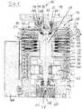
- the vacuum pump 10 showncomprises a pump inlet or suction opening 14 surrounded by an inlet flange 12 as well as several pump stages for conveying the gas present at the pump inlet 14 to an in Fig. 1 pump outlet not shown.
- the vacuum pump 10comprises a stator with a static housing 16 and a rotor arranged in the housing 16 with a rotor shaft 20 that is rotatably mounted about the rotor axis 18.
- the vacuum pump 10is designed as a turbomolecular pump and comprises several turbomolecular pump stages connected in series with one another for effective pumping, with several turbomolecular rotor disks 22 connected to the rotor shaft 20 and several turbomolecular stator disks 24 arranged in the axial direction between the rotor disks 22 and fixed in the housing 16, which are secured by spacer rings 26 are held at a desired axial distance from one another.
- the rotor disks 22 and stator disks 24provide an axial pumping action directed in the direction of the arrow 30 in a scoop area 28.
- the vacuum pump 10also comprises three Holweck pump stages which are arranged one inside the other in the radial direction and are connected in series with one another for pumping.
- the rotor-side part of the Holweck pump stagescomprises a rotor hub 32 connected to the rotor shaft 20 and two cylindrical-jacket-shaped Holweck rotor sleeves 34, 36 which are fastened to the rotor hub 32 and carried by the latter and which are coaxial with the rotor axis 18 are oriented and nested in one another in the radial direction.
- two cylinder jacket-shaped Holweck stator sleeves 38, 40are provided, which are also oriented coaxially to the rotor axis 18 and are nested in one another in the radial direction.
- the active pumping surfaces of the Holweck pump stageare each formed by the radial jacket surfaces of a Holweck rotor sleeve 34, 36 and a Holweck stator sleeve 38, 40, which lie opposite one another, forming a narrow radial Holweck gap.
- One of the active pumping surfacesis smooth, in the present case that of the Holweck rotor sleeve 34 or 36, and the opposite, active pumping surface of the Holweck stator sleeve 38, 40 has a structure with grooves running helically around the axis of rotation 18 in the axial direction in which the rotation of the rotor propels the gas and thereby pumps it.
- the rotatable mounting of the rotor shaft 20is brought about by a roller bearing 42 in the area of the pump outlet and a permanent magnetic bearing 44 in the area of the pump inlet 14.
- the permanent magnetic bearing 44comprises a rotor-side bearing half 46 and a stator-side bearing half 48, each of which comprises a ring stack of several permanent magnetic rings 50, 52 stacked on top of one another in the axial direction, the magnetic rings 50, 52 being opposite one another, forming a radial bearing gap 54.
- an emergency or catch bearing 56is provided, which is designed as an unlubricated roller bearing and runs idle during normal operation of the vacuum pump without contact and only comes into engagement with an excessive radial deflection of the rotor relative to the stator to create a radial stop for the To form rotor, which prevents a collision of the rotor-side structures with the stator-side structures.
- a conical injection-molded nut 58 with an outer diameter increasing towards the roller bearing 42is provided on the rotor shaft 20 and is in sliding contact with a scraper of a plurality of absorbent disks 60 impregnated with an operating medium, such as a lubricant .
- an operating mediumsuch as a lubricant .
- the operating mediumis transferred by capillary action from the operating medium storage via the scraper to the rotating injection nut 58 and, as a result of the centrifugal force, is conveyed along the injection nut 58 in the direction of the increasing outer diameter of the injection nut 58 to the roller bearing 42, where it has a lubricating function, for example Fulfills.
- the vacuum pumpcomprises a drive motor 62 for rotatingly driving the rotor, the rotor of which is formed by the rotor shaft 20.
- a control unit 64controls the drive motor 62.
- the turbomolecular pumping stagesprovide a pumping effect in the scoop area 28 in the direction of arrow 30.
- the vacuum pump 10can instead of that from the Fig. 1 apparent frontal pump inlet 14 or in addition to this pump inlet 14, for example, also have at least one lateral suction opening (cf. Fig. 2 ). As far as a suction opening is mentioned below, this can be arranged on an end face of the vacuum pump 10 or also laterally.
- Fig. 2shows a schematic sectional view of a lateral vacuum connection of an exemplary embodiment of a vacuum pump 101 according to the invention with a flange 110, here for example again a turbo-molecular pump, which can be connected via a suction opening 127 to a recipient 120, of which the flange is shown here, and is smaller for generating a pressure or equal to 10 -5 mbar, preferably to generate a pressure less than or equal to 10 -7 mbar, in particular to generate a pressure less than or equal to 10 -9 mbar, in which the recipient 120 is designed.
- a seal 70 according to the inventionis located between the flange 120 of the recipient and the flange 110 of the pump Fig.
- a force transmission structure 165 for mounting and dismounting the pump 101 on or from the flange 120 of the recipient, for example a chamber,comprises a bracket 150, a fastening screw 151 and spreading elements 152, 153. The structure of this arrangement will not be discussed in more detail at this point .
- a seal 70which (cf. the cross-sectional views of FIG Figures 4a to 4d ) comprises an elastomer core 72 and a jacket 74.
- the jacket 74surrounds the elastomer core 72 completely and is closed (ie the jacket 74 covers exactly 360 ° in the circumferential direction).
- the jacket 74is open on one side, the jacket 74 then covering less than 360 °, seen in the circumferential direction, ie leaving a part of the elastomer core exposed.
- the jacket 74can also be designed to overlap, that is to say the jacket 74 covers more than 360 ° when viewed in the circumferential direction.
- the jacket 74preferably covers more than half of the core 72 - viewed in the circumferential direction - that is, the jacket 74 preferably encompasses the core 72, as in FIG Figure 4b shown.
- the jacketconsequently covers an angular range of more than 180 °.
- Such an encompassing, non-closed jacket 74can alternatively also be used in the examples not claimed in FIG Figures 4c and 4d be provided so that they are then designed according to the invention.
- the example of Figure 4cillustrates that the seal 70 does not have to be a full seal, but can be a hollow seal so designated here, in which one or more cavities - according to Figure 4c for example, precisely one central cavity extending in the longitudinal direction within the core 72 can be formed.
- the cross-sectional shape of the seal 70 and / or of the core 72is basically arbitrary.
- Figure 4dillustrates that the seal 70 or the core 72 can also have an essentially angular cross section with, in particular, a rounded corner area.
- the cross sectioncan, for example, as in Figure 4d - be essentially square or rectangular. Elliptical or oval cross-sections are also possible. All of the aforementioned special properties (non-closed jacket, one or more cavities, cross-sectional shape, etc.) can in principle be combined with one another as required.
- a plurality of separate, identically or differently designed coresin particular adjacent to one another, to be surrounded by a common jacket.
- One or more corescan also be surrounded by a plurality of separate shells.
- the jacket 74 of the seal 70can consist of a material that contains PTFE plastic or PTFE-based plastic, or consist of a material containing FEP and / or PFA plastic.
- the elastomer core 72 of the seal 70can in particular consist of a material containing fluoroelastomer.
- the jacket 74 of the seal 70consists for example of a material containing FEP and / or PFA plastic.
- the thickness of the jacket 74 of the seal 70can in particular be in the range from 0.1 mm to 1.5 mm, whereby it is preferably in the range from 0.2 mm to 0.8 mm.
- the seal 70is provided as an O-seal, for example. However, it can in particular also be designed as a flat seal.
- a correspondingly designed vacuum connectioncan in principle also have an end suction opening, for example in the form of the Fig. 1 apparent pump inlet 14 include.
- two seals that are coaxial with one anothercan also be provided to seal the connection in question.
- at least the inner sealis provided with a jacket.
- the jacket of the inner sealis designed to be open or overlapping on the side facing the outer seal.
- meanscan be provided for suctioning off the area between the two seals.
- the outer sealcan be provided with or without a jacket.
- FIG. 3An example of such an application with two seals 70 which are coaxial to one another is shown Fig. 3 .
- the seals 70are arranged here between a cover 211 and a housing 202.
- An annular channel 214in which negative pressure is generated, is provided between the seals 70.
- a line 215is provided for this, which opens either into one of the pump stages of the vacuum pump 201 or into a gas outlet channel 230.
- a lower part assembly 203 and a shaft 204are shown, which is rotatably supported at a first end by a roller bearing 208 and at the opposite, vacuum-side end by a permanent magnet bearing 217, which is fixed in the housing 20 by a support structure 216.
- the pumping system of the pump 201comprises pump-active rotor structures 205 as well as pump-active stator structures 206 and spacers 207. Furthermore, drive means 209 are provided for the shaft 204. Vacuum chambers 220 and 221, which are connected to one another by a connection 225, are arranged in the housing 202 are. The chamber 220 is directly connected to the first pumping stage 222 of the pumping system. The chamber 221 is connected via a suction channel 210 to an intermediate inlet 218, via which gas can be admitted into the second pump stage 223. An opening 226 is provided for the chamber 221, through which, for example, a gas to be analyzed or a particle flow can be admitted.
- Vacuum connectionsare also conceivable in particular for vacuum accessories that are designed for pressures less than or equal to 10 -5 mbar, preferably for pressures less than or equal to 10 -7 mbar, in particular for pressures less than or equal to 10 -9 mbar.
- vacuum accessoriescan include, for example, flood or barrier gas valves, pressure sensors, temperature sensors, sight glasses, screens, gas regulating valves, high vacuum slides, ultra high vacuum slides and / or the like.
Landscapes
- Engineering & Computer Science (AREA)
- General Engineering & Computer Science (AREA)
- Mechanical Engineering (AREA)
- Non-Positive Displacement Air Blowers (AREA)
- Compressors, Vaccum Pumps And Other Relevant Systems (AREA)
- Gasket Seals (AREA)
Description
Translated fromGermanDie vorliegende Erfindung betrifft eine Abdichtung in einem Vakuumsystem, insbesondere eine Abdichtung einer Verbindung einer Vakuumpumpe, insbesondere Turbomolekularpumpe oder SplitFlow-Pumpe.The present invention relates to a seal in a vacuum system, in particular a seal of a connection of a vacuum pump, in particular a turbo-molecular pump or a split-flow pump.
Vakuumpumpen wie z.B. Turbomolekularpumpen werden in unterschiedlichen Bereichen der Technik eingesetzt, um ein für einen jeweiligen Prozess notwendiges Vakuum zu schaffen. Turbomolekularpumpen umfassen einen Stator mit mehreren in Richtung einer Rotorachse aufeinanderfolgenden Statorscheiben und einen relativ zu dem Stator um die Rotorachse drehbar gelagerten Rotor, der eine Rotorwelle und mehrere auf der Rotorwelle angeordnete, in axialer Richtung aufeinanderfolgende und zwischen den Statorscheiben angeordnete Rotorscheiben umfasst, wobei die Statorscheiben und die Rotorscheiben jeweils eine pumpaktive Struktur aufweisen. Eine ähnliche Vakuumpumpe ist z.B. aus
In der Vakuumtechnik werden als Dichtungen häufig Fluorelastomer-O-Ringe eingesetzt. Bei solchen Elastomerdichtungen kann es jedoch insbesondere bei niedrigeren Drücken zu einem Ausgasen kommen. Aufgrund einer solchen Ausgasung und auch aufgrund von Diffusion sind solche Elastomerdichtungen nur begrenzt einsetzbar. Auf dem Gebiet der sogenannten Vorpumpen beispielsweise, also in Druckbereichen von nicht weniger als etwa 10-4 mbar (10-2 Pa), kommt es noch nicht zu Problemen mit derartigen Dichtungen. Niedrigere Drücke sind mit solchen Dichtungen allerdings nicht mehr erreichbar. Bei Drücken kleiner oder gleich 10-5 mbar (kleiner oder gleich 10-3 Pa) kann das Ausgasen von Elastomerdichtungen zu einer signifikanten Verschlechterung der Vakuumwerte führen. Spätestens bei Drücken kleiner oder gleich 10-9 mbar (kleiner oder gleich 10-7 Pa) ist der Einsatz derartiger Elastomerdichtungen aufgrund der vorstehend erwähnten Problematik völlig ausgeschlossen.Fluoroelastomer O-rings are often used as seals in vacuum technology. In the case of such elastomer seals, however, outgassing can occur, especially at lower pressures. Due to such outgassing and also due to diffusion, such elastomer seals can only be used to a limited extent. In the field of so-called backing pumps, for example, that is to say in pressure ranges of not less than about 10-4 mbar (10-2 Pa), there are as yet no problems with such seals. However, lower pressures can no longer be achieved with such seals. At pressures less than or equal to 10-5 mbar (less than or equal to 10-3 Pa) the outgassing of elastomer seals can lead to a significant deterioration in the vacuum values. No later than at pressures less than or equal to 10-9 mbar (less than or equal to 10-7 Pa) the use of such elastomer seals is completely excluded because of the problems mentioned above.
Um dennoch elastomere Dichtungen bei niedrigeren Drücken einsetzen zu können, wurde bereits eine kombinierte Dichtung aus einer Elastomerdichtung und einer Spaltdichtung mit dazwischen angeordneter Absaugung vorgeschlagen. Eine solche kombinierte Dichtung ist jedoch relativ aufwändig.In order to nevertheless be able to use elastomer seals at lower pressures, a combined seal consisting of an elastomer seal and a gap seal with suction arranged in between has already been proposed. However, such a combined seal is relatively complex.
Es sind auch bereits sogenannte "CF-Dichtungen" bekannt, bei denen die einander gegenüberliegenden Flansche der Dichtung aus Edelstahl bestehen und zwischen die Edelstahlflansche ein Kupferdichtring eingesetzt wird. An den Edelstahlflanschen sind einstückig mit den Flanschen Schneidkanten ausgebildet, die sich in den Kupferring eindrücken oder einschneiden und dadurch abdichten. Solche Flansche werden auch Conflat-Flansche (eingetragene Marke der Agilent Technologies Inc., USA) genannt. Flansche dieser Art sind zwar bei Hoch- oder Ultrahochvakuumpumpen einsetzbar. Sie besitzen jedoch den Nachteil, dass sie infolge der dauerhaften Verformung nicht mehrfach einsetzbar sind und Flansche bzw. komplette Gehäuse aus Edelstahl voraussetzen, was relativ aufwändig und kostspielig ist.So-called "CF seals" are also known, in which the opposing flanges of the seal are made of stainless steel and a copper sealing ring is inserted between the stainless steel flanges. On the stainless steel flanges, cutting edges are formed in one piece with the flanges, which press or cut into the copper ring and thereby seal. Such flanges are also called Conflat flanges (registered trademark of Agilent Technologies Inc., USA). Flanges of this type can be used in high or ultra high vacuum pumps. However, they have the disadvantage that, due to the permanent deformation, they cannot be used repeatedly and require flanges or complete housings made of stainless steel, which is relatively complex and expensive.
Der Erfindung liegt die Aufgabe zugrunde, ein Vakuumsystem bzw. eine Vakuumpumpe der eingangs genannten Art anzugeben, bei der auch sehr niedrige Drücke mit möglichst einfachen und entsprechend kostengünstigen Dichtungen realisierbar sind.The invention is based on the object of specifying a vacuum system or a vacuum pump of the type mentioned at the beginning, in which even very low pressures can be achieved with the simplest possible and correspondingly inexpensive seals.
Die Aufgabe wird erfindungsgemäß durch eine Vakuumpumpe mit den Merkmalen des Anspruchs 1 und ein Vakuumsystem mit den Merkmalen des Anspruchs gelöst. Bevorzugte Ausführungsformen des erfindungsgemäßen Vakuumsystems bzw. der erfindungsgemäßen Vakuumpumpe ergeben sich aus den Unteransprüchen, der vorliegenden Beschreibung sowie der Zeichnung.The object is achieved according to the invention by a vacuum pump with the features of claim 1 and a vacuum system with the features of claim. Preferred embodiments of the vacuum system according to the invention or the vacuum pump according to the invention emerge from the subclaims, the present description and the drawing.
Die erfindungsgemäße Vakuumpumpe, insbesondere Turbomolekularpumpe oder SplitFlow-Pumpe, ist über wenigstens eine Ansaugöffnung mit einem Rezipienten verbindbar und zur Erzeugung eines Drucks kleiner oder gleich 10-5 mbar (kleiner oder gleich 10-3 Pa), vorzugsweise zur Erzeugung eines Drucks kleiner oder gleich 10-7 mbar (kleiner oder gleich 10-5 Pa), insbesondere zur Erzeugung eines Drucks kleiner oder gleich 10-9 mbar (kleiner oder gleich 10-7 Pa) in dem Rezipienten ausgeführt, wobei zur Abdichtung der Verbindung wenigstens eine Dichtung vorgesehen ist, die einen Kern, insbesondere einen Elastomerkern, sowie einen Mantel umfasst, der den Kern auf dessen der Ansaugöffnung zugewandten Seite umgibt.The vacuum pump according to the invention, in particular turbo-molecular pump or split-flow pump, can be connected to a recipient via at least one suction opening and to generate a pressure less than or equal to 10-5 mbar (less than or equal to 10-3 Pa), preferably to generate a pressure less than or equal to 10-7 mbar (less than or equal to 10-5 Pa), in particular to generate a pressure less than or equal to 10-9 mbar (less than or equal to 10-7 Pa) in the recipient, with at least one seal being provided to seal the connection , which comprises a core, in particular an elastomer core, and a jacket that surrounds the core on its side facing the suction opening.
Aufgrund dieser Ausbildung können nunmehr auch niedrigere Drücke mit relativ einfachen und entsprechend kostengünstigen Dichtungen realisiert werden. Man geht davon aus, dass die erfindungsgemäßen Dichtungen sogar in Druckbereichen von 10-8 bis 10-11 mbar (10-6 Pa bis 10-9 Pa) eingesetzt werden können. So kann der Mantel des Kerns, insbesondere des Elastomerkerns, im Wesentlichen ohne Beeinträchtigung der Elastizität der Dichtung so gewählt werden, dass das Ausgasen der Dichtung soweit wie möglich minimiert oder ganz verhindert wird, während die erforderliche Elastizität durch den Kern gewährleistet wird. Die jeweilige Dichtung ist nunmehr auch mehrmals einsetzbar. Zudem entfallen die relativ aufwändigen und teuren Edelstahlflansche bzw. Edelstahlgehäuse.Because of this design, lower pressures can now also be achieved with relatively simple and correspondingly inexpensive seals. It is assumed that the seals according to the invention can even be used in pressure ranges from 10-8 to 10-11 mbar (10-6 Pa to 10-9 Pa). Thus, the jacket of the core, in particular of the elastomer core, can be chosen essentially without impairing the elasticity of the seal so that the outgassing of the seal is minimized as far as possible or completely prevented, while the required elasticity is ensured by the core. The respective seal can now also be used several times. In addition, there is no need for the relatively complex and expensive stainless steel flanges or stainless steel housings.
Der Mantel der Dichtung besteht aus einem Material, das PTFE-(Polytetrafluorethylen)-Kunststoff oder auf PTFE basierenden Kunststoff enthält, oder aus einem Perfluorethylenpropylen-(FEP)- und/oder Perfluoralkoxylalkan-(PFA)-Kunststoff enthaltenden Material. Der Kern der Dichtung besteht vorteilhafterweise aus einem Fluorelastomer enthaltenden Material.The jacket of the seal is made of a material that contains PTFE (polytetrafluoroethylene) plastic or PTFE-based plastic, or of a material containing perfluoroethylene propylene (FEP) and / or perfluoroalkoxylalkane (PFA) plastic. The core of the seal advantageously consists of a material containing fluoroelastomer.
Der Kern kann beispielsweise aus FKM (Fluorkautschuk), VMQ (Silikon-Kautschuk) oder EPDM (Ethylen-Propylen-Dien-Kautschuk) oder aus einem FKM, VMQ oder EPDM enthaltenden Material bestehen.The core can for example consist of FKM (fluororubber), VMQ (silicone rubber) or EPDM (ethylene-propylene-diene rubber) or of a material containing FKM, VMQ or EPDM.
PTFE-Kunststoffe oder auf PTFE basierende Kunststoffe besitzen zwar bezüglich der Diffusion schlechtere Eigenschaften als z.B. Fluorelastomere, sie gasen jedoch bei niedrigeren Drücken weniger aus. Nachdem der Mantel im Vergleich zum Dichtungskern relativ dünn ausgeführt werden kann, macht der Mantel lediglich einen geringen Teil des Querschnitts der Dichtung aus, so dass die Diffusion durch den Mantel der Dichtung vernachlässigbar klein ist. Aufgrund der geringen Diffusion durch den insbesondere aus einem Fluorelastomer enthaltenden Material bestehenden Kern gelangen nur wenige Moleküle durch die Dichtung hindurch. Da der Mantel der Dichtung aus einem Material besteht, das PTFE-Kunststoff oder auf PTFE basierenden Kunststoff enthält, ist die Ausgasung aus der Dichtung in den Bereich niedrigen Drucks deutlich reduziert. Durch die Kombination dieser beiden genannten Effekte können somit wesentlich niedrigere Drücke erreicht werden als mit den üblichen Fluorelastomer-Dichtungen ohne Mantel. Der Kern der Dichtung, insbesondere ein Elastomer- bzw. Fluorelastomerkern, kann das gewünschte elastische Verhalten der Dichtung gewährleisten, womit diese mehrfach verwendbar ist, was bei reinen PTFE-Dichtungen nicht der Fall wäre.PTFE plastics or plastics based on PTFE have poorer diffusion properties than fluoroelastomers, for example, but they emit less gas at lower pressures. Since the jacket can be made relatively thin compared to the seal core, the jacket only makes up a small part of the cross section of the seal, so that the diffusion through the jacket of the seal is negligibly small. Because of the low diffusion through the core, which consists in particular of a material containing a fluoroelastomer, only a few molecules pass through the seal. Since the jacket of the seal is made of a material that contains PTFE plastic or PTFE-based plastic, outgassing from the seal in the area of low pressure is significantly reduced. By combining these two mentioned effects, significantly lower pressures can be achieved than with the usual fluoroelastomer seals without a jacket. The core of the seal, in particular an elastomer or fluoroelastomer core, can ensure the desired elastic behavior of the seal, so that it can be used several times, which would not be the case with pure PTFE seals.
Der Mantel der Dichtung besitzt vorteilhafterweise eine Dicke im Bereich von 0,1 mm bis 1,5 mm und insbesondere eine Dicke im Bereich von 0,2 mm bis 0,8 mm. Grundsätzlich sind auch geringere oder größere Dicken möglich.The jacket of the seal advantageously has a thickness in the range from 0.1 mm to 1.5 mm and in particular a thickness in the range from 0.2 mm to 0.8 mm. In principle, smaller or larger thicknesses are also possible.
Zur Abdichtung der Verbindung können insbesondere auch zumindest zwei ineinander liegende, insbesondere zueinander koaxiale, Dichtungen vorgesehen sein, wobei in diesem Fall zumindest eine innere Dichtung mit einem Mantel versehen sein kann.To seal the connection, in particular at least two seals lying one inside the other, in particular coaxial with one another, can be provided, in which case at least one inner seal can be provided with a jacket.
Der erfinderischen Verwendung der Dichtung entsprechend, ist auch für solche Abdichtung von Vorteil, wenn der Mantel der inneren Dichtung auf der der äußeren Dichtung zugewandten Seite offen oder überlappend ausgeführt ist und Mittel zur Absaugung des Bereichs zwischen den beiden Dichtungen vorgesehen sind. Mit einer solchen doppelten Dichtung können besonders niedrige Drücke erreicht werden.According to the inventive use of the seal, it is also advantageous for such a seal if the jacket of the inner seal is designed to be open or overlapping on the side facing the outer seal and means for suctioning the area between the two seals are provided. With such a double seal, particularly low pressures can be achieved.
Als äußere Dichtung kann eine Dichtung mit Mantel oder ohne Mantel zum Einsatz kommen. Die innere Dichtung ist zumindest teilweise mit einem Mantel versehen. Der Mantel der inneren Dichtung ist auf einer Seite offen oder überlappend ausgeführt, also nicht nahtlos bzw. geschlossen, so dass die offene bzw. überlappende Seite zur Zwischenabsaugung hin angeordnet ist. Ausgasende und diffundierte Teilchen werden durch die Zwischenabsaugung zwischen den Dichtungen abgesaugt. Die innere Dichtung muss also nicht mehr gegen Atmosphärendruck abdichten, wodurch Diffusionseffekte zur Seite des niedrigeren Drucks hin reduziert werden. Es können somit besonders niedrige Drücke erreicht werden.A seal with or without a jacket can be used as the outer seal. The inner seal is at least partially provided with a jacket. The jacket of the inner seal is designed to be open or overlapping on one side, ie not seamless or closed, so that the open or overlapping side is arranged for intermediate suction. Outgassing and diffused particles are sucked off through the intermediate suction between the seals. The inner seal no longer has to seal against atmospheric pressure, as a result of which diffusion effects on the side of the lower pressure are reduced. Particularly low pressures can thus be achieved.
Eine jeweilige Dichtung kann beispielsweise als O-Ring oder auch als Flachdichtung vorgesehen sein.A respective seal can be provided, for example, as an O-ring or as a flat seal.
Die jeweilige Dichtung kann im Querschnitt vollständig ausgefüllt sein oder einen oder mehrere Hohlräume aufweisen, d.h. es kann sich um eine Volldichtung oder um eine Hohldichtung handeln.The respective seal can be completely filled in cross section or have one or more cavities, i.e. it can be a full seal or a hollow seal.
Die Vakuumpumpe kann einen oder auch mehrere Vakuumanschlüsse besitzen. Im letzteren Fall können bestimmte Vakuumanschlüsse auch auf einem unterschiedlichen Druckniveau liegen. Die verschiedenen Vakuumanschlüsse können in derselben Ebene oder auch in unterschiedlichen Ebenen liegen.The vacuum pump can have one or more vacuum connections. In the latter case, certain vacuum connections can also be at different pressure levels. The various vacuum connections can be on the same level or on different levels.
Ein entsprechendes Vakuumzubehör kann sich dadurch auszeichnen, dass es für Drücke kleiner oder gleich 10-5 mbar (kleiner oder gleich 10-3 Pa), vorzugsweise für Drücke kleiner oder gleich 10-7 mbar (kleiner oder gleich 10-5 Pa), insbesondere für Drücke kleiner oder gleich 10-9 mbar (kleiner oder gleich 10-7 Pa) ausgelegt ist und wenigstens eine Dichtung aufweist, die einen Kern, insbesondere einen Elastomerkern, sowie einen Mantel umfasst, der den Kern zumindest teilweise umgibt.A corresponding vacuum accessory can be characterized in that it can be used for pressures less than or equal to 10-5 mbar (less than or equal to 10-3 Pa), preferably for pressures less than or equal to 10-7 mbar (less than or equal to 10-5 Pa), in particular is designed for pressures less than or equal to 10-9 mbar (less than or equal to 10-7 Pa) and has at least one seal which has a core, in particular a Elastomer core, as well as a jacket which at least partially surrounds the core.
Ein solches Vakuumzubehör kann beispielsweise Flut- oder Sperrgasventile, Drucksensoren, Temperatursensoren, Schaugläser, Blenden, Gasregulierventile, Hochvakuum-Schieber, Ultrahochvakuum-Schieber, Rezipienten, Vakuumkammern und/oder dergleichen umfassen.Such vacuum accessories can include, for example, flooding or sealing gas valves, pressure sensors, temperature sensors, sight glasses, screens, gas regulating valves, high vacuum slides, ultra high vacuum slides, recipients, vacuum chambers and / or the like.
Der Mantel der Dichtung des Vakuumzubehörs besteht bevorzugt aus einem Material, das PTFE-Kunststoff oder auf PTFE basierenden Kunststoff enthält. Der Kern der Dichtung kann insbesondere aus einem Fluorelastomer enthaltenden Material bestehen.The jacket of the seal of the vacuum accessory is preferably made of a material that contains PTFE plastic or PTFE-based plastic. The core of the seal can in particular consist of a material containing fluoroelastomer.
Ferner kann der Mantel der Dichtung aus einem FEP- und/oder PFA-Kunststoff enthaltenden Material bestehen.Furthermore, the jacket of the seal can consist of a material containing FEP and / or PFA plastic.
Von Vorteil ist insbesondere auch, wenn der Mantel der betreffenden Dichtung des Vakuumzubehörs eine Dicke im Bereich von 0,1 mm bis 1,5 mm und insbesondere eine Dicke im Bereich von 0,2 mm bis 0,8 mm besitzt.It is also particularly advantageous if the jacket of the relevant seal of the vacuum accessory has a thickness in the range from 0.1 mm to 1.5 mm and in particular a thickness in the range from 0.2 mm to 0.8 mm.
Auch bei einem solchen Vakuumzubehör können zur Abdichtung einer jeweiligen Verbindung insbesondere auch wieder zumindest zwei ineinander liegende Dichtungen vorgesehen sein, und zwar optional in den bereits vorstehend genannten Ausführungsmöglichkeiten.In the case of such a vacuum accessory, too, at least two seals lying one inside the other can again be provided in particular to seal a respective connection, specifically optionally in the design options already mentioned above.
Ein weiterer Aspekt der Erfindung betrifft die Verwendung einer Dichtung mit einem Kern, insbesondere einem Elastomerkern, und einem diesen zumindest teilweise umgebenden Mantel zur Abdichtung in einem Vakuumsystem, insbesondere zur Abdichtung einer Verbindung einer Vakuumpumpe, insbesondere Turbomolekularpumpe oder SplitFlow-Pumpe, mit einem Rezipienten und/oder einer Verbindung mit Vakuumzubehör, wobei das Vakuumsystem für Drücke oder zur Erzeugung von Drücken kleiner oder gleich 10-5 mbar, vorzugsweise für Drücke kleiner oder gleich 10-7 mbar, insbesondere für Drücke kleiner oder gleich 10-9 mbar, ausgelegt ist, und/oder wobei in dem Vakuumsystem auf zumindest einer Seite der Verbindung ein Druck kleiner oder gleich 10-5 mbar, vorzugsweise kleiner oder gleich 10-7 mbar, insbesondere kleiner oder gleich 10-9 mbar herrscht oder hergestellt wird.Another aspect of the invention relates to the use of a seal with a core, in particular an elastomer core, and a jacket that at least partially surrounds it for sealing in a vacuum system, in particular for sealing a connection between a vacuum pump, in particular a turbo-molecular pump or SplitFlow pump, with a recipient and / or a connection with vacuum accessories, wherein the vacuum system is designed for pressures or for generating pressures less than or equal to 10-5 mbar, preferably for pressures less than or equal to 10-7 mbar, in particular for pressures less than or equal to 10-9 mbar, and / or where in the vacuum system on at least one side of the connection a pressure less than or equal to 10-5 mbar, preferably less than or equal to 10-7 mbar, in particular less than or equal to 10-9 mbar, prevails or is established.
Der Mantel der Dichtung besteht aus einem Material, das PTFE-Kunststoff oder auf PTFE basierenden Kunststoff enthält, oder aus einem FEP- und/oder PFA-Kunststoff enthaltenden Material.The jacket of the seal is made of a material that contains PTFE plastic or PTFE-based plastic, or of a material containing FEP and / or PFA plastic.
Von Vorteil ist insbesondere auch, wenn der Kern der Dichtung aus einem Fluorelastomer enthaltenden Material besteht.It is also particularly advantageous if the core of the seal consists of a material containing fluoroelastomer.
Auch bezüglich der erfindungsgemäßen Verwendung ist wieder von Vorteil, wenn der Mantel der Dichtung eine Dicke im Bereich von 0,1 mm bis 1,5 mm und insbesondere eine Dicke im Bereich von 0,2 mm bis 0,8 mm besitzt.With regard to the use according to the invention, it is again advantageous if the jacket of the seal has a thickness in the range from 0.1 mm to 1.5 mm and in particular a thickness in the range from 0.2 mm to 0.8 mm.
Zur Abdichtung der betreffenden Verbindung können insbesondere auch wieder zumindest zwei ineinander liegende Dichtungen vorgesehen und zumindest die innere Dichtung mit einem Mantel versehen sein. Dabei ist der Mantel der inneren Dichtung wieder auf der der äußeren Dichtung zugewandten Seite offen oder überlappend ausgeführt. Dabei sind bevorzugt wieder Mittel zur Absaugung des Bereichs zwischen den beiden Dichtungen vorgesehen.To seal the connection in question, at least two seals lying one inside the other can again be provided and at least the inner seal can be provided with a jacket. The jacket of the inner seal is again designed to be open or overlapping on the side facing the outer seal. In this case, means are again provided for suctioning off the area between the two seals.
Wie ebenfalls bereits erwähnt, kann eine jeweilige Dichtung beispielsweise als O-Ring oder als Flachdichtung ausgeführt sein.As also already mentioned, a respective seal can be designed, for example, as an O-ring or as a flat seal.
Ein weiterer Aspekt der Erfindung betrifft ein Vakuumsystem mit zumindest einem ersten Gegenstand und einem zweiten Gegenstand, die über wenigstens eine Öffnung miteinander verbindbar oder verbunden sind, wobei zur Abdichtung der Verbindung wenigstens eine Dichtung vorgesehen ist, die einen Kern, insbesondere einen Elastomerkern, sowie einen Mantel umfasst, der den Kern auf dessen der Öffnung zugewandten Seite umgibt, und wobei in zumindest einem der Gegenstände ein Druck kleiner oder gleich 10-5 mbar, vorzugsweise kleiner oder gleich 10-7 mbar, insbesondere kleiner oder gleich 10-9 mbar herrscht oder, insbesondere mittels des anderen Gegenstandes, herstellbar ist.Another aspect of the invention relates to a vacuum system with at least a first object and a second object, which can be or are connected to one another via at least one opening, at least one seal being provided for sealing the connection, which has a core, in particular an elastomer core, and a Comprises jacket, which surrounds the core on its side facing the opening, and wherein in at least one of the objects there is a pressure less than or equal to 10-5 mbar, preferably less than or equal to 10-7 mbar, in particular less than or equal to 10-9 mbar or , in particular by means of the other object, can be produced.
Insbesondere ist vorgesehen, dass der Mantel den Kern im Querschnitt gesehen über mehr als die Hälfte, vorzugsweise über mehr als zwei Drittel, insbesondere über mehr als drei Viertel, von dessen Umfang umgibt. Bei dem Mantel handelt es sich hierbei also gerade nicht um eine beispielsweise zur Zentrierung dienende Anlage, an welcher der z.B. als O-Ring ausgebildete Kern lediglich anliegt und wie sie beispielsweise in Form eines insbesondere metallischen, im Querschnitt rechteckigen oder auch leicht gewölbten, den O-Ring z.B. mit einer leicht konkav geformten Seite aufnehmenden Zentrierrings bekannt ist.In particular, it is provided that the jacket surrounds the core over more than half, preferably over more than two thirds, in particular over more than three quarters, of its circumference when viewed in cross section. In this case, the jacket is not a system used for centering, for example, on which the core, for example designed as an O-ring, merely rests and, for example, in the form of a particularly metallic, rectangular in cross-section or also slightly curved, the O -Ring is known for example with a slightly concave side receiving centering ring.
Was mögliche Abmessungen der erfindungsgemäßen Dichtungen anbetrifft, so kann z.B. vorgesehen sein, dass die Stärke oder Dicke m des Mantels von der Stärke bzw. der so genannten Schnurstärke des Kerns k abhängig ist, wobei z.B. für 1,0mm ≤ k < 4mm ein Wert für m im Bereich von 0,2 bis 0,3mm, insbesondere von etwa 0,25mm, für 4mm ≤ k < 6mm ein Wert für m im Bereich von 0,3 bis 0,5mm, insbesondere von etwa 0,4mm, für 6mm ≤ k < 10mm ein Wert für m im Bereich von 0,4 bis 0,6mm, insbesondere von etwa 0,5mm, und für 10 mm ≤ k ≤ 20mm ein Wert für m im Bereich von 0,5 bis 0,9mm, insbesondere von etwa 0,8mm, gewählt wird.As far as possible dimensions of the seals according to the invention are concerned, it can be provided, for example, that the strength or thickness m of the jacket is dependent on the strength or the so-called cord strength of the core k, with a value for, for example, 1.0 mm k <4 mm m in the range from 0.2 to 0.3 mm, in particular from about 0.25 mm, for 4 mm k <6 mm, a value for m in the range from 0.3 to 0.5 mm, in particular from about 0.4 mm, for 6 mm k <10mm a value for m in the range from 0.4 to 0.6mm, in particular from about 0.5mm, and for 10mm k 20mm a value for m in the range from 0.5 to 0.9mm, in particular from about 0.8mm is chosen.
Wenn die Dichtung eine geschlossene Ringform aufweist und insbesondere als O-Ring-Dichtung ausgebildet ist, dann kann z.B. vorgesehen sein, dass die Stärke bzw. die so genannte Schnurstärke des Kerns k vom Innendurchmesser I der Dichtung abhängig ist, wobei z.B. für I ≥ etwa 5mm ein Wert für k im Bereich von 1,6 bis 2mm, insbesondere von etwa 1,8mm, für I ≥ etwa 7mm ein Wert für k im Bereich von 2,4 bis 2,8mm, insbesondere von etwa 2,6mm, für I ≥ etwa 12mm ein Wert für k im Bereich von 3,3 bis 3,7mm, insbesondere von etwa 3,5mm, für I ≥ etwa 20mm ein Wert für k im Bereich von 5 bis 5,6mm, insbesondere von etwa 5,3mm, und für I ≥ etwa 45mm ein Wert für k im Bereich von 6,6 bis 7,4mm, insbesondere von etwa 7mm, gewählt wird. Die maximalen Werte für den Innendurchmesser I können zwischen etwa 1.000mm und 1.600mm liegen.If the seal has a closed ring shape and is designed in particular as an O-ring seal, then it can be provided, for example, that the thickness or the so-called cord thickness of the core k is dependent on the inner diameter I of the seal, where, for example, I ≥ about 5mm, a value for k in the range from 1.6 to 2mm, in particular from around 1.8mm, for I ≥ around 7mm, a value for k in the range from 2.4 to 2.8mm, in particular from around 2.6mm, for I. ≥ about 12mm a value for k in the range from 3.3 to 3.7mm, in particular from about 3.5mm, for I ≥ about 20mm a value for k in the range from 5 to 5.6mm, in particular from about 5.3mm, and for I ≥ approximately 45 mm, a value for k in the range from 6.6 to 7.4 mm, in particular approximately 7 mm, is selected. The maximum values for the inside diameter I can be between approximately 1,000 mm and 1,600 mm.
Allgemein liegt der Erfindung somit der Gedanke zugrunde, dass mit den vorstehend angegebenen Dichtungen eine vakuumdichte Verbindung auch für sehr niedrige Druckbereiche realisiert, die Vakuumdichtigkeit also auch im Hochvakuum- und Ultrahochvakuumbereich gewährleistet werden kann, so dass diese Dichtungen auch für Turbomolekularpumpen bzw. SplitFlow-Pumpen sowie für im Hochvakuum- bzw. Ultrahochvakuumbereich einzusetzendes Vakuumzubehör verwendet werden können.In general, the invention is based on the idea that with the seals specified above, a vacuum-tight connection can also be realized for very low pressure ranges, i.e. the vacuum tightness can also be ensured in the high vacuum and ultra-high vacuum range, so that these seals can also be used for turbomolecular pumps or split-flow pumps as well as for vacuum accessories to be used in the high vacuum or ultra-high vacuum range.
Die Erfindung wird im Folgenden anhand eines Ausführungsbeispiels unter Bezugnahme auf die Zeichnung näher erläutert; in dieser zeigen:
- Fig. 1
- eine schematische Darstellung einer beispielhaften Ausführungsform einer Vakuumpumpe, bei der die Erfindung realisierbar ist,
- Fig. 2
- eine schematische Schnittdarstellung eines Vakuumanschlusses einer beispielhaften Ausführungsform einer erfindungsgemäßen Vakuumpumpe,
- Fig. 3
- eine schematische Schnittdarstellung eines Vakuumanschlusses einer weiteren beispielhaften Ausführungsform einer erfindungsgemäßen Vakuumpumpe, und
- Fig.
4a bis 4c - Beispiele für erfindungsgemäße und nicht beanspruchte (d.h. nicht erfindungsgemäße) Dichtungen jeweils in einer vergrößerten Querschnittsansicht.
- Fig. 1
- a schematic representation of an exemplary embodiment of a vacuum pump in which the invention can be implemented,
- Fig. 2
- a schematic sectional view of a vacuum connection of an exemplary embodiment of a vacuum pump according to the invention,
- Fig. 3
- a schematic sectional illustration of a vacuum connection of a further exemplary embodiment of a vacuum pump according to the invention, and
- Figures 4a to 4c
- Examples of seals according to the invention and not claimed (ie not according to the invention) each in an enlarged cross-sectional view.
Die in
Die Vakuumpumpe 10 ist als Turbomolekularpumpe ausgebildet und umfasst mehrere pumpwirksam miteinander in Serie geschaltete turbomolekulare Pumpstufen mit mehreren mit der Rotorwelle 20 verbundenen turbomolekularen Rotorscheiben 22 und mehreren in axialer Richtung zwischen den Rotorscheiben 22 angeordneten und in dem Gehäuse 16 festgelegten turbomolekularen Statorscheiben 24, die durch Distanzringe 26 in einem gewünschten axialen Abstand zueinander gehalten sind. Die Rotorscheiben 22 und Statorscheiben 24 stellen in einem Schöpfbereich 28 eine in Richtung des Pfeils 30 gerichtete axiale Pumpwirkung bereit.The
Die Vakuumpumpe 10 umfasst zudem drei in radialer Richtung ineinander angeordnete und pumpwirksam miteinander in Serie geschaltete Holweck-Pumpstufen. Der rotorseitige Teil der Holweck-Pumpstufen umfasst eine mit der Rotorwelle 20 verbundene Rotornabe 32 und zwei an der Rotornabe 32 befestigte und von dieser getragene zylindermantelförmige Holweck-Rotorhülsen 34, 36, die koaxial zu der Rotorachse 18 orientiert und in radialer Richtung ineinander geschachtelt sind. Ferner sind zwei zylindermantelförmige Holweck-Statorhülsen 38, 40 vorgesehen, die ebenfalls koaxial zu der Rotorachse 18 orientiert und in radialer Richtung ineinander geschachtelt sind. Die pumpaktiven Oberflächen der Holweck-Pumpstufe sind jeweils durch die einander unter Ausbildung eines engen radialen Holweck-Spalts gegenüberliegenden radialen Mantelflächen jeweils einer Holweck-Rotorhülse 34, 36 und einer Holweck-Statorhülse 38, 40 gebildet. Dabei ist jeweils eine der pumpaktiven Oberflächen glatt ausgebildet, im vorliegenden Fall die der Holweck-Rotorhülse 34 bzw. 36, und die gegenüberliegende pumpaktive Oberfläche der Holweck-Statorhülse 38, 40 weist eine Strukturierung mit schraubenlinienförmig um die Rotationsachse 18 herum in axialer Richtung verlaufenden Nuten auf, in denen durch die Rotation des Rotors das Gas vorangetrieben und dadurch gepumpt wird.The
Die drehbare Lagerung der Rotorwelle 20 wird durch ein Wälzlager 42 im Bereich des Pumpenauslasses und ein Permanentmagnetlager 44 im Bereich des Pumpeneinlasses 14 bewirkt.The rotatable mounting of the
Das Permanentmagnetlager 44 umfasst eine rotorseitige Lagerhälfte 46 und eine statorseitige Lagerhälfte 48, die jeweils einen Ringstapel aus mehreren in axialer Richtung aufeinander gestapelten permanentmagnetischen Ringen 50, 52 umfassen, wobei die Magnetringe 50, 52 unter Ausbildung eines radialen Lagerspalts 54 einander gegenüberliegen.The permanent
Innerhalb des Permanentmagnetlagers 44 ist ein Not- oder Fanglager 56 vorgesehen, das als ungeschmiertes Wälzlager ausgebildet ist und im normalen Betrieb der Vakuumpumpe ohne Berührung leerläuft und erst bei einer übermäßigen radialen Auslenkung des Rotors gegenüber dem Stator in Eingriff gelangt, um einen radialen Anschlag für den Rotor zu bilden, der eine Kollision der rotorseitigen Strukturen mit den statorseitigen Strukturen verhindert.Within the permanent
Im Bereich des Wälzlagers 42 ist an der Rotorwelle 20 eine konische Spritzmutter 58 mit einem zu dem Wälzlager 42 hin zunehmenden Außendurchmesser vorgesehen, die mit einem Abstreifer eines mehrere mit einem Betriebsmittel, wie z.B. einem Schmiermittel, getränkte saugfähige Scheiben 60 umfassenden Betriebsmittelspeichers in gleitendem Kontakt steht. Im Betrieb wird das Betriebsmittel durch kapillare Wirkung von dem Betriebsmittelspeicher über den Abstreifer auf die rotierende Spritzmutter 58 übertragen und infolge der Zentrifugalkraft entlang der Spritzmutter 58 in Richtung des größer werdenden Außendurchmessers der Spritzmutter 58 zu dem Wälzlager 42 hin gefördert, wo es z.B. eine schmierende Funktion erfüllt.In the area of the
Die Vakuumpumpe umfasst einen Antriebsmotor 62 zum drehenden Antreiben des Rotors, dessen Läufer durch die Rotorwelle 20 gebildet ist. Eine Steuereinheit 64 steuert den Antriebsmotor 62 an.The vacuum pump comprises a
Die turbomolekularen Pumpstufen stellen in dem Schöpfbereich 28 eine Pumpwirkung in Richtung des Pfeils 30 bereit.The turbomolecular pumping stages provide a pumping effect in the
Die Vakuumpumpe 10 kann anstelle des aus der
Dabei ist zur Abdichtung der Verbindung eine Dichtung 70 vorgesehen, die (vgl. die Querschnittsansichten der
In der in
Es können auch mehrere separate, identisch oder unterschiedlich ausgebildete, Kerne, insbesondere aneinander anliegend, von einem gemeinsamen Mantel umgeben sein. Auch können ein oder mehrere Kerne von mehreren separaten Mänteln umgeben sein.It is also possible for a plurality of separate, identically or differently designed cores, in particular adjacent to one another, to be surrounded by a common jacket. One or more cores can also be surrounded by a plurality of separate shells.
Erfindungsgemäß kann der Mantel 74 der Dichtung 70 aus einem Material bestehen, das PTFE-Kunststoff oder auf PTFE basierenden Kunststoff enthält, oder aus einem FEP- und/oder PFA-Kunststoff enthaltenden Material bestehen. Der Elastomerkern 72 der Dichtung 70 kann insbesondere aus einem Fluorelastomer enthaltenden Material bestehen.According to the invention, the
Im vorliegenden Fall besteht der Mantel 74 der Dichtung 70 beispielsweise aus einem FEP- und/oder PFA-Kunststoff enthaltenden Material.In the present case, the
Die Dicke des Mantels 74 der Dichtung 70 kann insbesondere im Bereich von 0,1 mm bis 1,5 mm liegen, wobei sie bevorzugt im Bereich von 0,2 mm bis 0,8 mm liegt.The thickness of the
Im vorliegenden Fall ist die Dichtung 70 beispielsweise als O-Dichtung vorgesehen. Sie kann jedoch insbesondere auch als Flachdichtung ausgeführt sein.In the present case, the
Während der Vakuumanschluss in der Darstellung gemäß
Zur Abdichtung der betreffenden Verbindung können beispielsweise auch zwei zueinander koaxiale Dichtungen vorgesehen sein. In diesem Fall ist zumindest die innere Dichtung mit einem Mantel versehen. Dabei ist der Mantel der inneren Dichtung erfindungsgemäß auf der der äußeren Dichtung zugewandten Seite offen oder überlappend ausgeführt. Dabei können insbesondere Mittel zur Absaugung des Bereichs zwischen den beiden Dichtungen vorgesehen sein. Die äußere Dichtung kann mit oder ohne Ummantelung vorgesehen sein.For example, two seals that are coaxial with one another can also be provided to seal the connection in question. In this case, at least the inner seal is provided with a jacket. According to the invention, the jacket of the inner seal is designed to be open or overlapping on the side facing the outer seal. In particular, means can be provided for suctioning off the area between the two seals. The outer seal can be provided with or without a jacket.
Ein Beispiel für eine solche Anwendung mit zwei zueinander koaxialen Dichtungen 70 zeigt
Die oben beschriebene Anordnung ist nur ein mögliches Beispiel für die Anwendung der erfindungsgemäßen Dichtungen 70.The arrangement described above is only one possible example for the application of the
Vakuumanschlüsse, wie z.B. vorstehend beschrieben, sind insbesondere auch bei Vakuumzubehör denkbar, das für Drücke kleiner oder gleich 10-5 mbar, vorzugsweise für Drücke kleiner oder gleich 10-7 mbar, insbesondere für Drücke kleiner oder gleich 10-9 mbar ausgelegt ist. Solches Vakuumzubehör kann beispielsweise Flut- oder Sperrgasventile, Drucksensoren, Temperatursensoren, Schaugläser, Blenden, Gasregulierventile, Hochvakuum-Schieber, Ultrahochvakuum-Schieber und/oder dergleichen umfassen.Vacuum connections, as described above, are also conceivable in particular for vacuum accessories that are designed for pressures less than or equal to 10-5 mbar, preferably for pressures less than or equal to 10-7 mbar, in particular for pressures less than or equal to 10-9 mbar. Such vacuum accessories can include, for example, flood or barrier gas valves, pressure sensors, temperature sensors, sight glasses, screens, gas regulating valves, high vacuum slides, ultra high vacuum slides and / or the like.
- 1010
- VakuumpumpeVacuum pump
- 1212
- EinlassflanschInlet flange
- 1414th
- Pumpeneinlass, AnsaugöffnungPump inlet, suction port
- 1616
- Gehäusecasing
- 1818th
- RotationsachseAxis of rotation
- 2020th
- RotorwelleRotor shaft
- 2222nd
- RotorscheibeRotor disk
- 2424
- StatorscheibeStator disc
- 2626th
- DistanzringSpacer ring
- 2828
- SchöpfbereichScoop area
- 3030th
- Pfeilarrow
- 3232
- RotornabeRotor hub
- 3434
- Holweck-RotorhülseHolweck rotor sleeve
- 3636
- Holweck-RotorhülseHolweck rotor sleeve
- 3838
- Holweck-StatorhülseHolweck stator sleeve
- 4040
- Holweck-StatorhülseHolweck stator sleeve
- 4242
- Wälzlagerroller bearing
- 4444
- PermanentmagnetlagerPermanent magnet bearings
- 4646
- rotorseitige Lagerhälfterotor-side bearing half
- 4848
- statorseitige Lagerhälftestator-side bearing half
- 5050
- permanentmagnetischer Ringpermanent magnetic ring
- 5252
- permanentmagnetischer Ringpermanent magnetic ring
- 5454
- radialer Lagerspaltradial bearing gap
- 5656
- Not- oder FanglagerEmergency or fishing camp
- 5858
- konische Spritzmutterconical injection nut
- 6060
- saugfähige Scheibeabsorbent disc
- 6262
- AntriebsmotorDrive motor
- 6464
- SteuereinheitControl unit
- 7070
- Dichtungpoetry
- 7272
- ElastomerkernElastomer core
- 7474
- Mantelcoat
- 7676
- Hohlraumcavity
Claims (10)
- A vacuum device, namely a vacuum pump (10), in particular a turbomolecular pump or a split-flow pump, which is connectable to a recipient via at least one suction opening and which is designed to generate a pressure of less than or equal to 10-5 mbar, preferably to generate a pressure of less than or equal to 10-7 mbar, in particular to generate a pressure of less than or equal to 10-9 mbar, in the recipient, wherein at least one seal (70) is provided to seal the connection,characterized in that the seal (70) comprises a core, in particular an elastomer core (72), and a jacket (74);
in that the jacket (74) of the seal (70) consists of a material which includes PTFE plastic or PTFE-based plastic or consists of a material including FEP plastic and/or PFA plastic;
in that the jacket (74) surrounds the core (72) at its side facing the suction opening; and
in that the jacket (74) is designed as open or overlapping at one side, in particular at its side remote from the suction opening. - A vacuum device in accordance with claim 1,
characterized in that the core of the seal consists of a material including a fluoroelastomer. - A vacuum device in accordance with at least one of the preceding claims,characterized in that the jacket of the seal has a thickness in the range from 0.1 mm to 1.5 mm and in particular has a thickness in the range from 0.2 mm to 0.8 mm.
- A vacuum device in accordance with at least one of the preceding claims,characterized in that the jacket (74) surrounds the core (72), viewed in cross-section, over more than half, preferably over more than two thirds, in particular over more than three quarters, of the periphery of the core (72).
- A vacuum device in accordance with at least one of the preceding claims,characterized in that the seal has a closed ring shape and is in particular designed as an O-ring seal or as a flat seal.
- A vacuum device in accordance with at least one of the preceding claims,characterized in that at least two seals one lying within the other one, which are in particular coaxial with respect to one another, are provided for sealing the connection and at least the inner seal is provided with the jacket,
with means in particular being provided for the suction of the region between the two seals. - A vacuum device in accordance with at least one of the preceding claims,characterized in that the jacket is configured as a coating, which is in particular fixedly connected to the core, or as a cover which is in particular not fixedly connected to the core.
- A vacuum system comprising at least a first object (10) and a second object which are connectable or connected to one another via at least one opening, wherein a pressure of less than or equal to 10-5 mbar, preferably of less than or equal to 10-7 mbar, in particular of less than or equal to 10-9 mbar, is present in at least one of the objects or can be produced, in particular by means of the other object (10),
wherein at least one seal (70) is provided for sealing the connection,characterized in that
the seal (70) comprises a core, in particular an elastomer core (72), and a jacket (74);
in that the jacket (74) of the seal (70) consists of a material which includes PTFE plastic or PTFE-based plastic or consists of a material including FEP plastic and/or PFA plastic;
in that the jacket (74) surrounds the core (72) at its side facing the opening; and
in that the jacket (74) is designed as open or overlapping at one side, in particular at its side remote from the opening. - Use of a seal (70) for sealing in a vacuum system (10) comprising at least a first object (10) and a second object which are connectable or connected to one another via at least one suction opening and/or opening, in particular for sealing a connection of a vacuum pump (10), in particular of a turbomolecular pump or a split-flow pump, to a recipient via the at least one suction opening and/or for sealing a connection to vacuum accessories via the at least one opening,
wherein the vacuum system is designed for pressures or for generating pressures of less than or equal to 10-5 mbar, preferably less than or equal to 10-7 mbar, in particular less than or equal to 10-9 mbar, and/or
wherein a pressure of less than or equal to 10-5 mbar, preferably of less than or equal to 10-7 mbar, in particular of less than or equal to 10-9 mbar, is present or is produced in the vacuum system at at least one side of the connection,
characterized in that the seal (70) which is used comprises a core, in particular an elastomer core (72), and a jacket (74), with the jacket (74) consisting of a material which includes PTFE plastic or PTFE-based plastic or consisting of a material including FEP plastic and/or PFA plastic, and with the jacket (74) being designed as open or overlapping at at least one side;
in that the seal is arranged such that the jacket (74) surrounds the core (72) at its side facing the suction opening or the opening; andin that the jacket (74) is designed as open or overlapping at one side, in particular at its side remote from the suction opening or the opening. - Use in accordance with claim 9,
characterized in that the core of the seal consists of a material including a fluoroelastomer.
Priority Applications (2)
| Application Number | Priority Date | Filing Date | Title |
|---|---|---|---|
| EP14195433.9AEP3026303B1 (en) | 2014-11-28 | 2014-11-28 | Vacuum pump, vacuum accessories and their sealing |
| JP2015231463AJP6744087B2 (en) | 2014-11-28 | 2015-11-27 | Vacuum pump and vacuum parts |
Applications Claiming Priority (1)
| Application Number | Priority Date | Filing Date | Title |
|---|---|---|---|
| EP14195433.9AEP3026303B1 (en) | 2014-11-28 | 2014-11-28 | Vacuum pump, vacuum accessories and their sealing |
Publications (2)
| Publication Number | Publication Date |
|---|---|
| EP3026303A1 EP3026303A1 (en) | 2016-06-01 |
| EP3026303B1true EP3026303B1 (en) | 2021-01-06 |
Family
ID=52102422
Family Applications (1)
| Application Number | Title | Priority Date | Filing Date |
|---|---|---|---|
| EP14195433.9AActiveEP3026303B1 (en) | 2014-11-28 | 2014-11-28 | Vacuum pump, vacuum accessories and their sealing |
Country Status (2)
| Country | Link |
|---|---|
| EP (1) | EP3026303B1 (en) |
| JP (1) | JP6744087B2 (en) |
Families Citing this family (4)
| Publication number | Priority date | Publication date | Assignee | Title |
|---|---|---|---|---|
| GB2563406A (en)* | 2017-06-13 | 2018-12-19 | Edwards Ltd | Vacuum seal |
| EP3650700B1 (en)* | 2018-11-09 | 2024-02-28 | Pfeiffer Vacuum Gmbh | Vacuum device |
| DE102020203260A1 (en) | 2019-03-28 | 2020-10-01 | Kabushiki Kaisha Toyota Jidoshokki | ELECTRIC COMPRESSOR |
| CN111605107A (en)* | 2020-06-18 | 2020-09-01 | 北京通嘉鼎元科技有限公司 | Machining method of sealing element, sealing element and vacuum pump |
Citations (3)
| Publication number | Priority date | Publication date | Assignee | Title |
|---|---|---|---|---|
| EP1852613A2 (en)* | 2006-05-04 | 2007-11-07 | Pfeiffer Vacuum Gmbh | Vacuum pump with casing |
| US20080309071A1 (en)* | 2007-06-15 | 2008-12-18 | Varian, Inc. | Split joint for vacuum pumps and method for obtaining thereof |
| EP2228540A2 (en)* | 2009-03-14 | 2010-09-15 | Pfeiffer Vacuum GmbH | Assembly with vacuum pump |
Family Cites Families (8)
| Publication number | Priority date | Publication date | Assignee | Title |
|---|---|---|---|---|
| JPS5517705A (en)* | 1978-07-20 | 1980-02-07 | Tokyo Inst Of Technol | Gasket for super high-vacuum |
| JPH11129398A (en)* | 1997-10-27 | 1999-05-18 | Daikin Ind Ltd | Perfluoro rubber laminate and method for producing the same |
| JPH11201289A (en)* | 1998-01-09 | 1999-07-27 | Nok Corp | Seal ring and manufacture therefor |
| JP2000055204A (en)* | 1998-08-05 | 2000-02-22 | Nok Corp | Manufacture of composite structure o-ring |
| GB0603318D0 (en)* | 2006-02-20 | 2006-03-29 | Boc Group Plc | Seal |
| GB0712779D0 (en)* | 2007-07-02 | 2007-08-08 | Edwards Ltd | Seal |
| JP5339620B2 (en)* | 2009-10-26 | 2013-11-13 | 淀川ヒューテック株式会社 | Annular sealing means and manufacturing method thereof |
| US20110204545A1 (en)* | 2010-02-25 | 2011-08-25 | Tanner Douglas E | Method of making high performance seals |
- 2014
- 2014-11-28EPEP14195433.9Apatent/EP3026303B1/enactiveActive
- 2015
- 2015-11-27JPJP2015231463Apatent/JP6744087B2/enactiveActive
Patent Citations (3)
| Publication number | Priority date | Publication date | Assignee | Title |
|---|---|---|---|---|
| EP1852613A2 (en)* | 2006-05-04 | 2007-11-07 | Pfeiffer Vacuum Gmbh | Vacuum pump with casing |
| US20080309071A1 (en)* | 2007-06-15 | 2008-12-18 | Varian, Inc. | Split joint for vacuum pumps and method for obtaining thereof |
| EP2228540A2 (en)* | 2009-03-14 | 2010-09-15 | Pfeiffer Vacuum GmbH | Assembly with vacuum pump |
Also Published As
| Publication number | Publication date |
|---|---|
| EP3026303A1 (en) | 2016-06-01 |
| JP2016102496A (en) | 2016-06-02 |
| JP6744087B2 (en) | 2020-08-19 |
Similar Documents
| Publication | Publication Date | Title |
|---|---|---|
| EP3347598B1 (en) | Turbo fan with cooling element | |
| EP3026303B1 (en) | Vacuum pump, vacuum accessories and their sealing | |
| EP1394365B1 (en) | Turbocharger shaft sealing | |
| EP3657021B1 (en) | Vacuum pump | |
| EP2933497B1 (en) | Vacuum pump | |
| DE102012005829A1 (en) | Diagonal fan | |
| EP2975268B1 (en) | Vacuum system | |
| EP2772650B1 (en) | Vacuum pump | |
| DE102017110087A1 (en) | A cassette sealing device and a bearing with such a cassette sealing device | |
| EP1706645B1 (en) | Multi-stage friction vacuum pump | |
| EP3318763B1 (en) | Vacuum seal, dual seal, vacuum system and vacuum pump | |
| DE102007044945A1 (en) | vacuum pump | |
| DE202012000611U1 (en) | Turbo molecular pump | |
| EP3085963B1 (en) | Vacuum pump | |
| EP1994315A1 (en) | Radial shaft seal | |
| EP3438460A1 (en) | Vacuum pump | |
| EP3371430A1 (en) | Coolant pump for an internal combustion engine | |
| EP2990656A2 (en) | Vacuum pump | |
| EP4194700A1 (en) | Vacuum pump with a holweck pump stage with variable holweck geometry | |
| DE102016100642A1 (en) | vacuum pump | |
| DE102015113821B4 (en) | Vacuum pump | |
| EP3339652B1 (en) | Vacuum pump with inner lining to receive deposits | |
| EP3327293B1 (en) | Vacuum pump having multiple inlets | |
| EP3767109B1 (en) | Vacuum system | |
| WO2015144342A1 (en) | Centrifugal seal for a turbomachine |
Legal Events
| Date | Code | Title | Description |
|---|---|---|---|
| PUAI | Public reference made under article 153(3) epc to a published international application that has entered the european phase | Free format text:ORIGINAL CODE: 0009012 | |
| AK | Designated contracting states | Kind code of ref document:A1 Designated state(s):AL AT BE BG CH CY CZ DE DK EE ES FI FR GB GR HR HU IE IS IT LI LT LU LV MC MK MT NL NO PL PT RO RS SE SI SK SM TR | |
| AX | Request for extension of the european patent | Extension state:BA ME | |
| STAA | Information on the status of an ep patent application or granted ep patent | Free format text:STATUS: REQUEST FOR EXAMINATION WAS MADE | |
| 17P | Request for examination filed | Effective date:20161201 | |
| RBV | Designated contracting states (corrected) | Designated state(s):AL AT BE BG CH CY CZ DE DK EE ES FI FR GB GR HR HU IE IS IT LI LT LU LV MC MK MT NL NO PL PT RO RS SE SI SK SM TR | |
| R17P | Request for examination filed (corrected) | Effective date:20161201 | |
| STAA | Information on the status of an ep patent application or granted ep patent | Free format text:STATUS: EXAMINATION IS IN PROGRESS | |
| 17Q | First examination report despatched | Effective date:20170301 | |
| REG | Reference to a national code | Ref country code:DE Ref legal event code:R079 Ref document number:502014015166 Country of ref document:DE Free format text:PREVIOUS MAIN CLASS: F16J0015020000 Ipc:F04D0019040000 | |
| GRAP | Despatch of communication of intention to grant a patent | Free format text:ORIGINAL CODE: EPIDOSNIGR1 | |
| STAA | Information on the status of an ep patent application or granted ep patent | Free format text:STATUS: GRANT OF PATENT IS INTENDED | |
| INTG | Intention to grant announced | Effective date:20200806 | |
| RIC1 | Information provided on ipc code assigned before grant | Ipc:F16J 15/02 20060101ALI20200724BHEP Ipc:F04D 19/04 20060101AFI20200724BHEP Ipc:F16J 15/10 20060101ALI20200724BHEP Ipc:F04D 29/08 20060101ALI20200724BHEP | |
| GRAS | Grant fee paid | Free format text:ORIGINAL CODE: EPIDOSNIGR3 | |
| GRAA | (expected) grant | Free format text:ORIGINAL CODE: 0009210 | |
| STAA | Information on the status of an ep patent application or granted ep patent | Free format text:STATUS: THE PATENT HAS BEEN GRANTED | |
| AK | Designated contracting states | Kind code of ref document:B1 Designated state(s):AL AT BE BG CH CY CZ DE DK EE ES FI FR GB GR HR HU IE IS IT LI LT LU LV MC MK MT NL NO PL PT RO RS SE SI SK SM TR | |
| REG | Reference to a national code | Ref country code:GB Ref legal event code:FG4D Free format text:NOT ENGLISH | |
| REG | Reference to a national code | Ref country code:AT Ref legal event code:REF Ref document number:1352664 Country of ref document:AT Kind code of ref document:T Effective date:20210115 Ref country code:CH Ref legal event code:EP | |
| REG | Reference to a national code | Ref country code:DE Ref legal event code:R096 Ref document number:502014015166 Country of ref document:DE | |
| REG | Reference to a national code | Ref country code:IE Ref legal event code:FG4D Free format text:LANGUAGE OF EP DOCUMENT: GERMAN | |
| REG | Reference to a national code | Ref country code:NL Ref legal event code:MP Effective date:20210106 | |
| REG | Reference to a national code | Ref country code:LT Ref legal event code:MG9D | |
| PG25 | Lapsed in a contracting state [announced via postgrant information from national office to epo] | Ref country code:BG Free format text:LAPSE BECAUSE OF FAILURE TO SUBMIT A TRANSLATION OF THE DESCRIPTION OR TO PAY THE FEE WITHIN THE PRESCRIBED TIME-LIMIT Effective date:20210406 Ref country code:NO Free format text:LAPSE BECAUSE OF FAILURE TO SUBMIT A TRANSLATION OF THE DESCRIPTION OR TO PAY THE FEE WITHIN THE PRESCRIBED TIME-LIMIT Effective date:20210406 Ref country code:NL Free format text:LAPSE BECAUSE OF FAILURE TO SUBMIT A TRANSLATION OF THE DESCRIPTION OR TO PAY THE FEE WITHIN THE PRESCRIBED TIME-LIMIT Effective date:20210106 Ref country code:GR Free format text:LAPSE BECAUSE OF FAILURE TO SUBMIT A TRANSLATION OF THE DESCRIPTION OR TO PAY THE FEE WITHIN THE PRESCRIBED TIME-LIMIT Effective date:20210407 Ref country code:FI Free format text:LAPSE BECAUSE OF FAILURE TO SUBMIT A TRANSLATION OF THE DESCRIPTION OR TO PAY THE FEE WITHIN THE PRESCRIBED TIME-LIMIT Effective date:20210106 Ref country code:HR Free format text:LAPSE BECAUSE OF FAILURE TO SUBMIT A TRANSLATION OF THE DESCRIPTION OR TO PAY THE FEE WITHIN THE PRESCRIBED TIME-LIMIT Effective date:20210106 Ref country code:PT Free format text:LAPSE BECAUSE OF FAILURE TO SUBMIT A TRANSLATION OF THE DESCRIPTION OR TO PAY THE FEE WITHIN THE PRESCRIBED TIME-LIMIT Effective date:20210506 Ref country code:LT Free format text:LAPSE BECAUSE OF FAILURE TO SUBMIT A TRANSLATION OF THE DESCRIPTION OR TO PAY THE FEE WITHIN THE PRESCRIBED TIME-LIMIT Effective date:20210106 | |
| PG25 | Lapsed in a contracting state [announced via postgrant information from national office to epo] | Ref country code:SE Free format text:LAPSE BECAUSE OF FAILURE TO SUBMIT A TRANSLATION OF THE DESCRIPTION OR TO PAY THE FEE WITHIN THE PRESCRIBED TIME-LIMIT Effective date:20210106 Ref country code:PL Free format text:LAPSE BECAUSE OF FAILURE TO SUBMIT A TRANSLATION OF THE DESCRIPTION OR TO PAY THE FEE WITHIN THE PRESCRIBED TIME-LIMIT Effective date:20210106 Ref country code:RS Free format text:LAPSE BECAUSE OF FAILURE TO SUBMIT A TRANSLATION OF THE DESCRIPTION OR TO PAY THE FEE WITHIN THE PRESCRIBED TIME-LIMIT Effective date:20210106 Ref country code:LV Free format text:LAPSE BECAUSE OF FAILURE TO SUBMIT A TRANSLATION OF THE DESCRIPTION OR TO PAY THE FEE WITHIN THE PRESCRIBED TIME-LIMIT Effective date:20210106 | |
| PG25 | Lapsed in a contracting state [announced via postgrant information from national office to epo] | Ref country code:IS Free format text:LAPSE BECAUSE OF FAILURE TO SUBMIT A TRANSLATION OF THE DESCRIPTION OR TO PAY THE FEE WITHIN THE PRESCRIBED TIME-LIMIT Effective date:20210506 | |
| REG | Reference to a national code | Ref country code:DE Ref legal event code:R097 Ref document number:502014015166 Country of ref document:DE | |
| PG25 | Lapsed in a contracting state [announced via postgrant information from national office to epo] | Ref country code:EE Free format text:LAPSE BECAUSE OF FAILURE TO SUBMIT A TRANSLATION OF THE DESCRIPTION OR TO PAY THE FEE WITHIN THE PRESCRIBED TIME-LIMIT Effective date:20210106 Ref country code:SM Free format text:LAPSE BECAUSE OF FAILURE TO SUBMIT A TRANSLATION OF THE DESCRIPTION OR TO PAY THE FEE WITHIN THE PRESCRIBED TIME-LIMIT Effective date:20210106 | |
| PLBE | No opposition filed within time limit | Free format text:ORIGINAL CODE: 0009261 | |
| STAA | Information on the status of an ep patent application or granted ep patent | Free format text:STATUS: NO OPPOSITION FILED WITHIN TIME LIMIT | |
| PG25 | Lapsed in a contracting state [announced via postgrant information from national office to epo] | Ref country code:SK Free format text:LAPSE BECAUSE OF FAILURE TO SUBMIT A TRANSLATION OF THE DESCRIPTION OR TO PAY THE FEE WITHIN THE PRESCRIBED TIME-LIMIT Effective date:20210106 Ref country code:RO Free format text:LAPSE BECAUSE OF FAILURE TO SUBMIT A TRANSLATION OF THE DESCRIPTION OR TO PAY THE FEE WITHIN THE PRESCRIBED TIME-LIMIT Effective date:20210106 Ref country code:DK Free format text:LAPSE BECAUSE OF FAILURE TO SUBMIT A TRANSLATION OF THE DESCRIPTION OR TO PAY THE FEE WITHIN THE PRESCRIBED TIME-LIMIT Effective date:20210106 Ref country code:ES Free format text:LAPSE BECAUSE OF FAILURE TO SUBMIT A TRANSLATION OF THE DESCRIPTION OR TO PAY THE FEE WITHIN THE PRESCRIBED TIME-LIMIT Effective date:20210106 | |
| 26N | No opposition filed | Effective date:20211007 | |
| PG25 | Lapsed in a contracting state [announced via postgrant information from national office to epo] | Ref country code:AL Free format text:LAPSE BECAUSE OF FAILURE TO SUBMIT A TRANSLATION OF THE DESCRIPTION OR TO PAY THE FEE WITHIN THE PRESCRIBED TIME-LIMIT Effective date:20210106 | |
| PG25 | Lapsed in a contracting state [announced via postgrant information from national office to epo] | Ref country code:SI Free format text:LAPSE BECAUSE OF FAILURE TO SUBMIT A TRANSLATION OF THE DESCRIPTION OR TO PAY THE FEE WITHIN THE PRESCRIBED TIME-LIMIT Effective date:20210106 | |
| PG25 | Lapsed in a contracting state [announced via postgrant information from national office to epo] | Ref country code:IS Free format text:LAPSE BECAUSE OF FAILURE TO SUBMIT A TRANSLATION OF THE DESCRIPTION OR TO PAY THE FEE WITHIN THE PRESCRIBED TIME-LIMIT Effective date:20210506 | |
| PG25 | Lapsed in a contracting state [announced via postgrant information from national office to epo] | Ref country code:MC Free format text:LAPSE BECAUSE OF FAILURE TO SUBMIT A TRANSLATION OF THE DESCRIPTION OR TO PAY THE FEE WITHIN THE PRESCRIBED TIME-LIMIT Effective date:20210106 | |
| REG | Reference to a national code | Ref country code:CH Ref legal event code:PL | |
| PG25 | Lapsed in a contracting state [announced via postgrant information from national office to epo] | Ref country code:LU Free format text:LAPSE BECAUSE OF NON-PAYMENT OF DUE FEES Effective date:20211128 Ref country code:BE Free format text:LAPSE BECAUSE OF NON-PAYMENT OF DUE FEES Effective date:20211130 | |
| REG | Reference to a national code | Ref country code:BE Ref legal event code:MM Effective date:20211130 | |
| PG25 | Lapsed in a contracting state [announced via postgrant information from national office to epo] | Ref country code:IE Free format text:LAPSE BECAUSE OF NON-PAYMENT OF DUE FEES Effective date:20211128 | |
| PG25 | Lapsed in a contracting state [announced via postgrant information from national office to epo] | Ref country code:FR Free format text:LAPSE BECAUSE OF NON-PAYMENT OF DUE FEES Effective date:20211130 | |
| REG | Reference to a national code | Ref country code:AT Ref legal event code:MM01 Ref document number:1352664 Country of ref document:AT Kind code of ref document:T Effective date:20211128 | |
| PG25 | Lapsed in a contracting state [announced via postgrant information from national office to epo] | Ref country code:AT Free format text:LAPSE BECAUSE OF NON-PAYMENT OF DUE FEES Effective date:20211128 | |
| PG25 | Lapsed in a contracting state [announced via postgrant information from national office to epo] | Ref country code:HU Free format text:LAPSE BECAUSE OF FAILURE TO SUBMIT A TRANSLATION OF THE DESCRIPTION OR TO PAY THE FEE WITHIN THE PRESCRIBED TIME-LIMIT; INVALID AB INITIO Effective date:20141128 | |
| PG25 | Lapsed in a contracting state [announced via postgrant information from national office to epo] | Ref country code:CY Free format text:LAPSE BECAUSE OF FAILURE TO SUBMIT A TRANSLATION OF THE DESCRIPTION OR TO PAY THE FEE WITHIN THE PRESCRIBED TIME-LIMIT Effective date:20210106 | |
| PG25 | Lapsed in a contracting state [announced via postgrant information from national office to epo] | Ref country code:LI Free format text:LAPSE BECAUSE OF NON-PAYMENT OF DUE FEES Effective date:20220630 Ref country code:CH Free format text:LAPSE BECAUSE OF NON-PAYMENT OF DUE FEES Effective date:20220630 | |
| PG25 | Lapsed in a contracting state [announced via postgrant information from national office to epo] | Ref country code:MK Free format text:LAPSE BECAUSE OF FAILURE TO SUBMIT A TRANSLATION OF THE DESCRIPTION OR TO PAY THE FEE WITHIN THE PRESCRIBED TIME-LIMIT Effective date:20210106 | |
| PG25 | Lapsed in a contracting state [announced via postgrant information from national office to epo] | Ref country code:MT Free format text:LAPSE BECAUSE OF FAILURE TO SUBMIT A TRANSLATION OF THE DESCRIPTION OR TO PAY THE FEE WITHIN THE PRESCRIBED TIME-LIMIT Effective date:20210106 | |
| PGFP | Annual fee paid to national office [announced via postgrant information from national office to epo] | Ref country code:GB Payment date:20241120 Year of fee payment:11 | |
| PGFP | Annual fee paid to national office [announced via postgrant information from national office to epo] | Ref country code:CZ Payment date:20241119 Year of fee payment:11 | |
| PGFP | Annual fee paid to national office [announced via postgrant information from national office to epo] | Ref country code:IT Payment date:20241126 Year of fee payment:11 | |
| PGFP | Annual fee paid to national office [announced via postgrant information from national office to epo] | Ref country code:DE Payment date:20250128 Year of fee payment:11 |