EP3024300B1 - An induction cooking hob including a cooking area with three or more induction coils and a method for controlling a cooking area - Google Patents
An induction cooking hob including a cooking area with three or more induction coils and a method for controlling a cooking areaDownload PDFInfo
- Publication number
- EP3024300B1 EP3024300B1EP15197985.3AEP15197985AEP3024300B1EP 3024300 B1EP3024300 B1EP 3024300B1EP 15197985 AEP15197985 AEP 15197985AEP 3024300 B1EP3024300 B1EP 3024300B1
- Authority
- EP
- European Patent Office
- Prior art keywords
- induction
- cooking
- induction coils
- power
- activated
- Prior art date
- Legal status (The legal status is an assumption and is not a legal conclusion. Google has not performed a legal analysis and makes no representation as to the accuracy of the status listed.)
- Active
Links
Images

Classifications
- H—ELECTRICITY
- H05—ELECTRIC TECHNIQUES NOT OTHERWISE PROVIDED FOR
- H05B—ELECTRIC HEATING; ELECTRIC LIGHT SOURCES NOT OTHERWISE PROVIDED FOR; CIRCUIT ARRANGEMENTS FOR ELECTRIC LIGHT SOURCES, IN GENERAL
- H05B6/00—Heating by electric, magnetic or electromagnetic fields
- H05B6/02—Induction heating
- H05B6/06—Control, e.g. of temperature, of power
- H05B6/062—Control, e.g. of temperature, of power for cooking plates or the like
- H05B6/065—Control, e.g. of temperature, of power for cooking plates or the like using coordinated control of multiple induction coils
- H—ELECTRICITY
- H05—ELECTRIC TECHNIQUES NOT OTHERWISE PROVIDED FOR
- H05B—ELECTRIC HEATING; ELECTRIC LIGHT SOURCES NOT OTHERWISE PROVIDED FOR; CIRCUIT ARRANGEMENTS FOR ELECTRIC LIGHT SOURCES, IN GENERAL
- H05B6/00—Heating by electric, magnetic or electromagnetic fields
- H05B6/02—Induction heating
- H05B6/10—Induction heating apparatus, other than furnaces, for specific applications
- H05B6/12—Cooking devices
- H05B6/1209—Cooking devices induction cooking plates or the like and devices to be used in combination with them
- H05B6/1245—Cooking devices induction cooking plates or the like and devices to be used in combination with them with special coil arrangements
- H05B6/1272—Cooking devices induction cooking plates or the like and devices to be used in combination with them with special coil arrangements with more than one coil or coil segment per heating zone
- H—ELECTRICITY
- H05—ELECTRIC TECHNIQUES NOT OTHERWISE PROVIDED FOR
- H05B—ELECTRIC HEATING; ELECTRIC LIGHT SOURCES NOT OTHERWISE PROVIDED FOR; CIRCUIT ARRANGEMENTS FOR ELECTRIC LIGHT SOURCES, IN GENERAL
- H05B2213/00—Aspects relating both to resistive heating and to induction heating, covered by H05B3/00 and H05B6/00
- H05B2213/05—Heating plates with pan detection means
- Y—GENERAL TAGGING OF NEW TECHNOLOGICAL DEVELOPMENTS; GENERAL TAGGING OF CROSS-SECTIONAL TECHNOLOGIES SPANNING OVER SEVERAL SECTIONS OF THE IPC; TECHNICAL SUBJECTS COVERED BY FORMER USPC CROSS-REFERENCE ART COLLECTIONS [XRACs] AND DIGESTS
- Y02—TECHNOLOGIES OR APPLICATIONS FOR MITIGATION OR ADAPTATION AGAINST CLIMATE CHANGE
- Y02B—CLIMATE CHANGE MITIGATION TECHNOLOGIES RELATED TO BUILDINGS, e.g. HOUSING, HOUSE APPLIANCES OR RELATED END-USER APPLICATIONS
- Y02B40/00—Technologies aiming at improving the efficiency of home appliances, e.g. induction cooking or efficient technologies for refrigerators, freezers or dish washers
Definitions
- the present inventionrelates to an induction cooking hob including at least one cooking area comprises at least three induction coils according to the preamble of claim 1. Further, the present invention relates to a method for controlling a cooking area.
- Cookwaremay be put onto an arbitrary position of the cooking area by the user.
- a pot detection devicerecognizes said position, so that the heating elements below the cookware may be activated.
- audible interferencemay be generate, if the difference between the instant powers of adjacent activated induction coils corresponds with differences between frequencies within the range of audible interference.
- DE 10 2006 054 973 A1discloses an induction cooking hob comprising two cooking areas. Each cooking area includes six elongated induction coils arranged side-by-side. The longitudinal axes of said induction coils are arranged in parallel. Each induction coil is associated with a dedicated induction generator and at least one pot detection device. The induction coils are controllable independent from each other. The induction coils covered by a cooking vessel may be functionally combined.
- US 2012/0024835 A1discloses a cooking hob comprising a plurality of heating elements.
- a detection assemblyis provided for detecting a position and size of a cooking vessel.
- a plurality of heating elementsis combined to a heating zone by a control unit depending on the detected size and position of the cooking vessel.
- a bottom surface of the cooking vesselis calculated. The total heat output is determined depending on the power level and bottom surface.
- WO 2012/095732 A1discloses an induction heating system with self-regulating power control.
- the power delivered to the induction coilis automatically selectable between a minimum value and a maximum value.
- the maximum valueis determined by the quality of the cooking vessel, the position of said cooking vessel or a power value set by the user.
- the induction coilhas a special asymmetric design.
- the density of turnsvaries on the area of said induction coil.
- the power supplied to the cooking vesselcan be varied by displacing said cooking vessel to a position with another density of turns.
- EP 2 034 800 A1discloses an induction cooking hob with a number of induction coils.
- a group of induction coilsis formed, so that said group is adapted to a selectable position of a cooking vessel.
- Each induction coilis associated with a dedicated induction generator.
- At least two induction coilsare synchronized, so that a phase relationship between said induction coils is adjusted.
- US 2012/0321762 A1discloses an induction cooking hob, wherein the cooking zone is subdivided into at least two cooking sub-zones.
- the cooking sub-zonesare heated by at least one heating unit.
- a cohesive heatingmay be formed during a joint operation of said cooking sub-zones.
- the same poweris applied to all activated cooking sub-zones.
- the cooking sub-zonesare operated independently from each other.
- the object of the present inventionis achieved by the induction cooking hob according to claim 1.
- the main idea of the present inventionis the geometric properties of the cooking area and the induction coils on the one hand and the dedicated induction generator for each induction coil of the cooking area on the other hand.
- the geometric properties of the cooking area and the induction coilsallow a number of arrangements of cookware with different shapes.
- the dedicated induction generator for each induction coilallows an independent setting of power of each induction coil.
- the cooking modeallows the user to change the preset pattern from the user interface to obtain the best pattern for the cooking needs at every instance.
- the requested poweris about 400 W, if the cooking vessel is placed on one of the extreme parts of the cooking area, and the requested power is about 3000 W, if the cooking vessel is placed on the other extreme part of the cooking area.
- the induction coils of at least one cooking areahave an oval and/or elliptical shape.
- the induction generatorsare connected or connectable to at least two different current lines, wherein said current lines have different phases.
- control unitmay be provided for performing at least one further cooking mode, wherein the activated induction coils work with one single setting of the requested power.
- control unitmay be provided for performing at least one further cooking mode with at least two different settings of requested powers, wherein at least one activated induction coil works with the setting of one requested power and at least one other activated induction coil works with the setting of another requested power.
- the cooking areacomprises four induction coils.
- the induction cooking hobmay comprise a number of pot detection devices, wherein each induction coil is associated to at least one pot detection device.
- the object of the present inventionis further achieved by the method according to claim 8.
- the methodfor controlling a cooking area on an induction cooking hob mentioned above, wherein the cooking area comprises at least three induction coils and said method comprises the steps of:
- the requested poweris about 400 W, if the cooking vessel is placed on one of the extreme parts of the cooking area, and the requested power is about 3000 W, if the cooking vessel is placed on the other extreme part of the cooking area.
- the pot detectionis performed, if the cooking vessel is moved or removed, in order to ensure that only the relevant induction coil or induction coils is or are active.
- the desired average power for each induction coil over the period of one or more selected cycle patternsmay be equal to the requested power for said induction coil.
- the instant powers of the activated induction coilsmay be as low as possible.
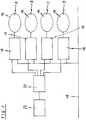
- FIG 1illustrates a schematic circuit diagram of a cooking area 12 for an induction cooking hob 10 according to a preferred embodiment of the present invention.
- the cooking area 12comprises four induction coils 14 arranged side-by side.
- the four induction coils 14form a line.
- a first, second, third and fourth induction coil 14is denoted by the letter A, B, C and D, respectively.
- the cooking area 12comprises four induction generators 16, a current line 18, a control unit 20 and a user interface 22.
- the current line 18is provided for supplying rectified mains voltage.
- the current line 18is connected to power input terminals of the four induction generators 16.
- Each induction generator 16corresponds with one induction coil 14.
- An output terminal of each induction generator 16is connected to the associated induction coil 14.
- the user interface 22is connected to an input terminal of the control unit 20.
- Four output terminals of the control unit 20are connected to corresponding control input terminals of the induction generators 16.
- the induction generator 16is realized by a half-bridge inverter.
- Each induction coil 14is associated to at least one pot detection device.
- the user interface 22may comprise dedicated touch keys for said cooking modes.
- the following four cooking modesare provided.
- the four induction coils A, B, C and Dwork with one single power setting.
- the four induction coils A, B, C and Dwork with two different power settings, wherein the first and second induction coils A and B work with one power setting and the third and fourth induction coils C and D work with another power setting.
- the four induction coils A, B, C and Dwork with two different power settings, wherein the first induction coil A works with one power setting and the second, third and fourth induction coils B, C and D work with another power setting.
- the four induction coils A, B, C and Dwork with two different power settings, wherein the first, second and third induction coils A, B and C work with one power setting and the fourth induction coil D works with another power setting.
- the third and fourth cooking modesare the same in view of a functional aspect.
- the induction coils 14 covered by cookwareare activated at the same working frequency in order to cancel acoustic interference noise.
- the induction coils 14are affected by different power settings and therefore by different frequencies, so that acoustic interference noise has to be avoided.
- the acoustic interference noiseoccurs, if the frequency difference between adjacent induction coils 14 is within the audible range of the human ear. Since the power is set by the user, the frequency depends on the power setting, so that often the frequency difference may be within the audible range.
- the induction coils 14are activated and deactivated according to a number of subsequent cycle patterns T1 to T11, in which not all of the induction coils 14 are activated during the same time.
- the sum of the instant powers iP of the activated induction coils 14is kept in such a way that the differences of the instant powers iP between the cycle patterns T1 to T11 are small.
- the variance of the instant powers iPmust be small enough in order to comply with existing norms for flickering on the current line 18.
- the used cycle patterns T1 to T11are structured in such a way that adjacent activated induction coils 14 have a small or no frequency difference. In contrast, the activated induction coils 14, which are not adjacent, may have different frequencies and powers.
- the induction coils 14 activated at a certain timeshould have a total instant power iP, which is equal to the sum of all requested powers rP.
- a variation of the total instant power iP between the cycle patterns T1 to T11may be allowed with the scope of the EMC norms.
- the following tableillustrates the possible combinations of activated and deactivated induction coils A, B, C and D, in which two, three or four of the induction coils A, B, C and D are activated at the same time.
- the first induction coil Ais adjacent to the second induction coil B, in turn the second induction coil B is adjacent to the third induction coil C, and the third induction coil C is adjacent to the fourth induction coil D, as shown in FIG 1 .
- the second line to the fifth line of said tableindicate the activated and deactivated states of the induction coils A, B, C and D, respectively.
- the eleven different cycle patternsare denoted by T1 to T11 in the first line.
- the last line of the tableindicates the number N of the simultaneously activated induction coils A, B, C and D.
- T1 T2 T3 T4 T5 T6 T7 T8 T9T10 T11 A x x x x x x x x x x B x x x x x x X C x x x x x X x X D x x x x x x x x x x x x x x x x x x N 4 3 3 3 3 3 2 2 2 2 2 2 2 2 2 2 2 2 2
- a number of the cycle patterns T1 to T11is selected from the above table.
- a relative cycle time t for each selected cycle pattern T1 to T11 and a power balance between the induction coils A, B, C and Dis set in such a way, that the desired average power for each induction coil A, B, C and D is achieved over one or more cycle patterns T1 to T11.
- the instant power iP of the individual induction coils A, B, C and Ddepends on the number of activated induction coils A, B, C and D, the selected power balance and the total requested power rP.
- the following tableillustrates the default individual duty settings of the induction coils A, B, C and D for each cycle pattern T1 to T11.
- the numerical values in the second line to the fifth line of said tableindicate the percentages of the power of the induction coils A, B, C and D, respectively.
- the last line of the tableindicates the number N of the simultaneously activated induction coils A, B, C and D.
- T1 T2 T3 T4 T5 T6 T7 T8 T9 T10 T11A 0.25 0.33 0.33 0.33 0.5 0.5 0.5 B 0.25 0.33 0.33 0.33 0.5 0.5 0.5 C 0.25 0.33 0.33 0.33 0.5 0.5 D 0.25 0.33 0.33 0.33 0.5 0.5 N 4 3 3 3 3 3 2 2 2 2 2 2 2 2 2 2 2 2 2 2 2 2 2 2 2 2 2
- the cycle patterns T6, T7 and T11can be selected as the preferred last cycle patterns, wherein the power balance between two activated induction coils A, B, C and/or D can be adjusted in order to achieve the desired power distributions.
- the activated induction coils A, B, C and/or D of the cycle patterns T6, T7 and T11are not adjacent.
- the activated induction coils A, B, C and/or D of the cycle patterns T6, T7 and T11may have arbitrary frequencies without generating acoustic interference noise.
- the method of selecting the cycle patterns and setting the dutyare performed as follows.
- a cycle pattern with three activated induction coils B, C and Dis selected, wherein the induction coil A is omitted, which has a requested power rP closest to the difference between the highest and second highest requested power rP.
- a further cycle patternis selected with two activated induction coils C and D having the highest and second highest requested power rP until the power is reach for the second highest power.
- Another cycle patternis selected with two activated induction coils A and D having the highest requested power iP and the biggest distance from each other. The power balance of the activated induction coils A and D is adjusted in order to reach the requested power rP.
- the cycle patterns T5, T9 and T11are selected.
- the relative cycle time t of the cycle pattern T9is calculated in such a way, that the instant power iP of the third induction coil C during the cycle pattern T5 is reached.
- the relative cycle time t of the cycle pattern T11is given as the remaining time.
- the following tableillustrates the relative cycle times t, the instant powers iP, the actual powers aP and the requested powers rP of the cycle patterns T1 to T11 according to the first example.
- T1 T2 T3 T4 T5 T6 T7 T8 T9T10 T11 aP rP t 0 0 0 0 0.45 0 0 0 0.40 0 0.15 iP (A) 0 0 666.7 100 100 iP (B) 333 0 0 150 150 iP (C) 333 500 0 350 350 iP (D) 333 500 333.3 400 400 Sum 1000 1000 1000 1000 1000 1000 1000 1000 1000 1000 1000 1000 1000 1000 1000 1000 1000 1000 1000 1000 1000 1000 1000 1000 1000 1000 1000 1000 1000 1000 1000 1000 1000 1000 1000 1000 1000 1000 1000 1000 1000 1000 1000 1000 1000 1000 1000 1000 1000 1000 1000 1000 1000 1000 1000 1000 1000 1000 1000 1000 1000 1000 1000 1000 1000 1000 1000 1000 1000 1000 1000 1000 1000 1000 1000 1000 1000 1000 1000 1000 1000 1000 1000 1000 1000 1000 1000 1000 1000 1000 1000 1000 1000 1000 1000 1000 1000
- the cooking zones associated to the second, third and fourth induction coils B, C and Dare always linked.
- other combinations of cycle patternsare used.
- FIG 2illustrates a schematic top view of the induction cooking hob 10 according to the preferred embodiment of the present invention.
- a small cooking vessel 28 and a big cooking vessel 30are arranged on the induction cooking hob 10.
- FIG 2relates to the second example.
- the induction cooking hob 10comprises a cooking area 12 including the four induction coils 14 arranged in series. Moreover, the induction cooking hob 10 comprises two further induction coils 24 and 26. The four induction coils 14 are elliptical, while the further induction coils 24 and 26 are circular. The longitudinal axes of the four induction coils 14 are arranged in parallel.
- the small cooking vessel 28is arranged above the first induction coil A, while the big cooking vessel 30 is arranged above the second, third and fourth induction coils B, C and D. The positions of the small cooking vessel 28 and the big cooking vessel 30 relates to the second example.
- the second examplediffers between two cases. In a first case the power setting of the first induction coil A is lower than the individual requested powers rP of the other induction coils B, C and D, while in a second case the power setting of the first induction coil A is higher than the individual requested powers rP of the other induction coils B, C and D.
- cycle patterns T1 and T5are applied.
- the cycle pattern T1is applied until the requested power for the first induction coil A is reached, while the cycle pattern T5 is applied during the rest of the time.
- the sum of the instant powers iP of all activated induction coils A, B, C and/or Dis always equal to the sum of the requested powers rP.
- the cycle pattern T1there are four activated induction coils A, B, C and D, so that the instant powers of each induction coil A, B, C and D is a quarter of the sum of the requested powers.
- the power setting of the first induction coil Ais higher than the individual requested powers rP of the other induction coils B, C and D.
- cycle patterns T2 and T11are applied.
- the cycle pattern T2is applied until the requested powers for the second and third induction coils B and C are reached.
- the cycle pattern T11the instant powers of the first and fourth induction coils A and D are matched in order to obtain the requested powers for said first and fourth induction coils A and D.
- the sum of the instant powers iPis always equal to the sum of the requested powers rP.
- the cycle pattern T2there are three activated induction coils A, B and C, so that the instant power of each induction coil A, B and C is a third of the sum of the requested powers.
- the power balance of said two induction coils A and Dcan be arbitrarily adjusted in order to obtain the desired power for both induction coils A and D.
- T1 T2 T3 T4 T5 T6 T7 T8 T9 T10 T11 aP rP t 0 0.5 0 0 0 0 0 0 0 0 0 0.5 1 iP200 400 300 300 iP (B) 200 100 100 iP (C) 200 100 100 iP (D) 200 100 100 Sum 600 600 600 600
- FIG 3illustrates a further schematic top view of the induction cooking hob according to the preferred embodiment of the present invention.
- Two medium cooking vessels 32 and 34are arranged on the induction cooking hob 10.
- FIG 3relates to an example with two current lines on different phases.
- the induction cooking hob 10comprises the cooking area 12 including the four induction coils 14 arranged in series. Additionally, the induction cooking hob 10 comprises the two further induction coils 24 and 26.
- the four induction coils 14are elliptical, while the further induction coils 24 and 26 are circular.
- the longitudinal axes of the four induction coils 14are arranged in parallel.
- a first medium cooking vessel 32is arranged above the first induction coil A and the second induction coil B, while a second medium cooking vessel 34 is arranged above the third induction coil C and the fourth induction coil D.
- the first induction coil A and the second induction coil Bare supplied by a first current line
- the third induction coil C and the fourth induction coil Dare supplied by a second current line, wherein the first and second current lines are on different phases.
- the adjacent induction coils A, B, C and/or Dcannot be activated at the same time with a frequency difference within the audible range.
- the sum of the instant powers iP of the first and second induction coils A and Bshould be constant.
- the sum of the instant powers iP of the third and fourth induction coils C and Dshould also be constant.
- T1 T2 T3A x x B x x C x x D x x
- the following tableillustrates the relative cycle times t, the instant powers iP, the actual powers aP and the requested powers rP of the cycle patterns T1 to T3 according to an example, in which the first induction coil A and the second induction coil B are supplied by the first current line, while the third induction coil C and the fourth induction coil D are supplied by the second current line, wherein the first and second current lines are on different phases.
- T1 T2 T3aP rP t 0 0.5 0.5 iP(A) 350 980 0 490 500 iP(B) 350 0 980 490 500 iP(C) 350 420 0 210 200 iP(D) 350 0 420 210 200 Sum 1400 1400 1400 1400 1400 1400 1400 1400
- the cycle pattern T1is applied the full time. However, if the above requested powers are different, then the cycle patterns T2 and T3 are applied, wherein the relative cycle time t is 0.5 or 50 %.
- the sum of the instant powers iP of the first induction coil A and the second induction coil Bis equal to the sum of the corresponding requested powers rP.
- the sum of the instant powers iP of the third induction coil C and the fourth induction coil Dis equal to the sum of the corresponding requested powers rP.
- the present inventionrelates to the activation of a cooking mode, wherein the requested power (rP) changes automatically according to the position of the cooking vessel on the cooking area.
- the systemperforms a pot detection on all coils in the cooking area. Depending on which coil or coils) that is (are) covered by the cooking vessel, power is applied to the coil (coils) according to a preset pattern.
- the requested power (rP)can for instance be low, for example about 400 W, if the cooking vessel is placed on one of the extreme parts of the cooking area. In contrast, the requested power (rP) can be high, for example about 3000 W, if the cooking vessel is placed on the other (opposite) extreme part of the cooking area.
- the requested powercan have an average value, if the cooking vessel is placed on a central portion of the cooking area, between the extreme parts.
- a usercould be allowed to change the preset pattern from the user interface to obtain the best pattern for the cooking needs at every instance.
- pair of coilscould be utilised as the defining regions of preset power, e.g. if a vessel is placed on coils A+B a high power is applied, if placed on coils B+C a medium power I applied and if placed on coils C+D a low power is applied.
- a new pot detectioncan be performed to ensure that only the relevant coil or coils are active.
Landscapes
- Physics & Mathematics (AREA)
- Electromagnetism (AREA)
- Induction Heating Cooking Devices (AREA)
Description
- The present invention relates to an induction cooking hob including at least one cooking area comprises at least three induction coils according to the preamble of claim 1. Further, the present invention relates to a method for controlling a cooking area.
- On cooking hobs, in particular on induction cooking hobs, there is a present trend that the cooking zones are not arranged in fixed places, but are flexibly put together by one or more heating elements. Cookware may be put onto an arbitrary position of the cooking area by the user. A pot detection device recognizes said position, so that the heating elements below the cookware may be activated.
- However, it is difficult to set the appropriate powers for the relevant heating elements. Further, audible interference may be generate, if the difference between the instant powers of adjacent activated induction coils corresponds with differences between frequencies within the range of audible interference.
DE 10 2006 054 973 A1 discloses an induction cooking hob comprising two cooking areas. Each cooking area includes six elongated induction coils arranged side-by-side. The longitudinal axes of said induction coils are arranged in parallel. Each induction coil is associated with a dedicated induction generator and at least one pot detection device. The induction coils are controllable independent from each other. The induction coils covered by a cooking vessel may be functionally combined.US 2012/0024835 A1 discloses a cooking hob comprising a plurality of heating elements. A detection assembly is provided for detecting a position and size of a cooking vessel. A plurality of heating elements is combined to a heating zone by a control unit depending on the detected size and position of the cooking vessel. A bottom surface of the cooking vessel is calculated. The total heat output is determined depending on the power level and bottom surface.WO 2012/095732 A1 discloses an induction heating system with self-regulating power control. The power delivered to the induction coil is automatically selectable between a minimum value and a maximum value. The maximum value is determined by the quality of the cooking vessel, the position of said cooking vessel or a power value set by the user. The induction coil has a special asymmetric design. The density of turns varies on the area of said induction coil. The power supplied to the cooking vessel can be varied by displacing said cooking vessel to a position with another density of turns.EP 2 034 800 A1 discloses an induction cooking hob with a number of induction coils. A group of induction coils is formed, so that said group is adapted to a selectable position of a cooking vessel. Each induction coil is associated with a dedicated induction generator. At least two induction coils are synchronized, so that a phase relationship between said induction coils is adjusted.US 2012/0321762 A1 discloses an induction cooking hob, wherein the cooking zone is subdivided into at least two cooking sub-zones. The cooking sub-zones are heated by at least one heating unit. A cohesive heating may be formed during a joint operation of said cooking sub-zones. In one operation mode the same power is applied to all activated cooking sub-zones. In another operation mode the cooking sub-zones are operated independently from each other.- It is an object of the present invention to provide an improved induction cooking hob with a cooking area and an improved method for controlling the power of the induction coils of the cooking area.
- The object of the present invention is achieved by the induction cooking hob according to claim 1.
- According to the present invention:
- instant powers of the induction generators within a cycle pattern are controlled or controllable independent from each other by the control unit,
- the sum of the instant powers of the activated induction coils within each selected cycle pattern is equal to the sum of the requested powers for each used induction coil, and
- a cooking mode is to be activated, in which the requested power is automatically changed according to the position of the cooking vessel on the cooking area, wherein the requested power is low, if the cooking vessel is placed on one of the extreme parts of the cooking area, the requested power is high, if the cooking vessel is placed on the other extreme part of the cooking area, and the requested power has an average value, if the cooking vessel is placed on a central portion of the cooking area.
- The main idea of the present invention is the geometric properties of the cooking area and the induction coils on the one hand and the dedicated induction generator for each induction coil of the cooking area on the other hand. The geometric properties of the cooking area and the induction coils allow a number of arrangements of cookware with different shapes. The dedicated induction generator for each induction coil allows an independent setting of power of each induction coil. The cooking mode allows the user to change the preset pattern from the user interface to obtain the best pattern for the cooking needs at every instance.
- For example, the requested power is about 400 W, if the cooking vessel is placed on one of the extreme parts of the cooking area, and the requested power is about 3000 W, if the cooking vessel is placed on the other extreme part of the cooking area.
- Preferably, the induction coils of at least one cooking area have an oval and/or elliptical shape.
- For example, the induction generators are connected or connectable to the same current line.
- Alternatively, the induction generators are connected or connectable to at least two different current lines, wherein said current lines have different phases.
- Further, the control unit may be provided for performing at least one further cooking mode, wherein the activated induction coils work with one single setting of the requested power.
- Moreover, the control unit may be provided for performing at least one further cooking mode with at least two different settings of requested powers, wherein at least one activated induction coil works with the setting of one requested power and at least one other activated induction coil works with the setting of another requested power.
- In particular, the cooking area comprises four induction coils.
- Furthermore, the induction cooking hob may comprise a number of pot detection devices, wherein each induction coil is associated to at least one pot detection device.
- The object of the present invention is further achieved by the method according to claim 8.
- According to the present invention, the method is provided for controlling a cooking area on an induction cooking hob mentioned above, wherein the cooking area comprises at least three induction coils and said method comprises the steps of:
- setting a requested power for each used induction coil by a user interface,
- selecting a number of subsequent cycle patterns from a table stored in a memory of a control unit,
- defining activated and deactivated induction coils by each selected cycle pattern,
- determining a cycle time for each selected cycle pattern and a power balance between the activated induction coils, so that a desired average power for each induction coil is obtained over a period of one or more selected cycle patterns, wherein the sum of the instant powers of the activated induction coils within each selected cycle pattern is equal to the sum of the requested powers for each used induction coil,
- performing a pot detection on all induction coils in the cooking area, and
- activating a cooking mode, in which the requested power is automatically changed according to the position of the cooking vessel on the cooking area, wherein the requested power is low, if the cooking vessel is placed on one of the extreme parts of the cooking area, the requested power is high, if the cooking vessel is placed on the other extreme part of the cooking area, and the requested power has an average value, if the cooking vessel is placed on a central portion of the cooking area.
- For example, the requested power is about 400 W, if the cooking vessel is placed on one of the extreme parts of the cooking area, and the requested power is about 3000 W, if the cooking vessel is placed on the other extreme part of the cooking area.
- In particular, the pot detection is performed, if the cooking vessel is moved or removed, in order to ensure that only the relevant induction coil or induction coils is or are active.
- Further, the desired average power for each induction coil over the period of one or more selected cycle patterns may be equal to the requested power for said induction coil.
- Preferably, as many induction coils as possible are activated within one cycle patterns.
- In a similar way, the instant powers of the activated induction coils may be as low as possible.
- In particular, variations of the instant powers of the activated induction coils are as low as possible.
- At last, the method is provided for the induction cooking hob mentioned above.
- Novel and inventive features of the present invention are set forth in the appended claims.
- The present invention will be described in further detail with reference to the accompanied drawings, in which
- FIG 1
- illustrates a schematic circuit diagram of a cooking area for an induction cooking hob according to a preferred embodiment of the present invention,
- FIG 2
- illustrates a schematic top view of the induction cooking hob according to the preferred embodiment of the present invention, and
- FIG 3
- illustrates a further schematic top view of the induction cooking hob according to the preferred embodiment of the present invention.
FIG 1 illustrates a schematic circuit diagram of acooking area 12 for aninduction cooking hob 10 according to a preferred embodiment of the present invention.- The
cooking area 12 comprises fourinduction coils 14 arranged side-by side. In this example, the fourinduction coils 14 form a line. A first, second, third andfourth induction coil 14 is denoted by the letter A, B, C and D, respectively. Further, thecooking area 12 comprises fourinduction generators 16, acurrent line 18, acontrol unit 20 and auser interface 22. Thecurrent line 18 is provided for supplying rectified mains voltage. Thecurrent line 18 is connected to power input terminals of the fourinduction generators 16. Eachinduction generator 16 corresponds with oneinduction coil 14. An output terminal of eachinduction generator 16 is connected to the associatedinduction coil 14. Theuser interface 22 is connected to an input terminal of thecontrol unit 20. Four output terminals of thecontrol unit 20 are connected to corresponding control input terminals of theinduction generators 16. For example, theinduction generator 16 is realized by a half-bridge inverter. Eachinduction coil 14 is associated to at least one pot detection device. - By operating the
user interface 22 different cooking modes can be selected by a user. For example, theuser interface 22 may comprise dedicated touch keys for said cooking modes. In a preferred embodiment the following four cooking modes are provided. According to a first cooking mode, the four induction coils A, B, C and D work with one single power setting. According to a second cooking mode, the four induction coils A, B, C and D work with two different power settings, wherein the first and second induction coils A and B work with one power setting and the third and fourth induction coils C and D work with another power setting. According to a third cooking mode, the four induction coils A, B, C and D work with two different power settings, wherein the first induction coil A works with one power setting and the second, third and fourth induction coils B, C and D work with another power setting. According to a fourth cooking mode, the four induction coils A, B, C and D work with two different power settings, wherein the first, second and third induction coils A, B and C work with one power setting and the fourth induction coil D works with another power setting. The third and fourth cooking modes are the same in view of a functional aspect. - In the first cooking mode, the induction coils 14 covered by cookware are activated at the same working frequency in order to cancel acoustic interference noise. However, in the second, third and fourth cooking modes, the induction coils 14 are affected by different power settings and therefore by different frequencies, so that acoustic interference noise has to be avoided. The acoustic interference noise occurs, if the frequency difference between adjacent induction coils 14 is within the audible range of the human ear. Since the power is set by the user, the frequency depends on the power setting, so that often the frequency difference may be within the audible range.
- In order to avoid the acoustic interference noise, the induction coils 14 are activated and deactivated according to a number of subsequent cycle patterns T1 to T11, in which not all of the induction coils 14 are activated during the same time. The sum of the instant powers iP of the activated induction coils 14 is kept in such a way that the differences of the instant powers iP between the cycle patterns T1 to T11 are small. In general, the variance of the instant powers iP must be small enough in order to comply with existing norms for flickering on the
current line 18. The used cycle patterns T1 to T11 are structured in such a way that adjacent activatedinduction coils 14 have a small or no frequency difference. In contrast, the activatedinduction coils 14, which are not adjacent, may have different frequencies and powers. - The induction coils 14 activated at a certain time should have a total instant power iP, which is equal to the sum of all requested powers rP. However, a variation of the total instant power iP between the cycle patterns T1 to T11 may be allowed with the scope of the EMC norms.
- The following table illustrates the possible combinations of activated and deactivated induction coils A, B, C and D, in which two, three or four of the induction coils A, B, C and D are activated at the same time. The first induction coil A is adjacent to the second induction coil B, in turn the second induction coil B is adjacent to the third induction coil C, and the third induction coil C is adjacent to the fourth induction coil D, as shown in
FIG 1 . The second line to the fifth line of said table indicate the activated and deactivated states of the induction coils A, B, C and D, respectively. The eleven different cycle patterns are denoted by T1 to T11 in the first line. The last line of the table indicates the number N of the simultaneously activated induction coils A, B, C and D.T1 T2 T3 T4 T5 T6 T7 T8 T9 T10 T11 A x x x x X x x B x x x x x x X C x x x x X x X D x x x x x x x N 4 3 3 3 3 2 2 2 2 2 2 - A number of the cycle patterns T1 to T11 is selected from the above table. A relative cycle time t for each selected cycle pattern T1 to T11 and a power balance between the induction coils A, B, C and D is set in such a way, that the desired average power for each induction coil A, B, C and D is achieved over one or more cycle patterns T1 to T11. The instant power iP of the individual induction coils A, B, C and D depends on the number of activated induction coils A, B, C and D, the selected power balance and the total requested power rP. It is preferred, that as many induction coils A, B, C and D as possible are activated within the given cycle pattern T1 to T11, so that the variation of the instant powers iP of the induction coils A, B, C and D are minimized, and that the power is uniform.
- The following table illustrates the default individual duty settings of the induction coils A, B, C and D for each cycle pattern T1 to T11. The numerical values in the second line to the fifth line of said table indicate the percentages of the power of the induction coils A, B, C and D, respectively. The last line of the table indicates the number N of the simultaneously activated induction coils A, B, C and D.
T1 T2 T3 T4 T5 T6 T7 T8 T9 T10 T11 A 0.25 0.33 0.33 0.33 0.5 0.5 0.5 B 0.25 0.33 0.33 0.33 0.5 0.5 0.5 C 0.25 0.33 0.33 0.33 0.5 0.5 0.5 D 0.25 0.33 0.33 0.33 0.5 0.5 0.5 N 4 3 3 3 3 2 2 2 2 2 2 - In particular, the cycle patterns T6, T7 and T11 can be selected as the preferred last cycle patterns, wherein the power balance between two activated induction coils A, B, C and/or D can be adjusted in order to achieve the desired power distributions. The activated induction coils A, B, C and/or D of the cycle patterns T6, T7 and T11 are not adjacent. Thus, the activated induction coils A, B, C and/or D of the cycle patterns T6, T7 and T11 may have arbitrary frequencies without generating acoustic interference noise.
- According to a first example, the requested power rP for the first induction coil A is rP = 100 W, for the second induction coil B is rP = 150 W, for the third induction coil C is rP = 350 W, and for the fourth induction coil D is rP = 400 W.
- In said first example, the method of selecting the cycle patterns and setting the duty are performed as follows. A cycle pattern with three activated induction coils B, C and D is selected, wherein the induction coil A is omitted, which has a requested power rP closest to the difference between the highest and second highest requested power rP. A further cycle pattern is selected with two activated induction coils C and D having the highest and second highest requested power rP until the power is reach for the second highest power. Another cycle pattern is selected with two activated induction coils A and D having the highest requested power iP and the biggest distance from each other. The power balance of the activated induction coils A and D is adjusted in order to reach the requested power rP. Thus, the cycle patterns T5, T9 and T11 are selected.
- The relative cycle time t of the cycle pattern T5 is calculated in such a way, that the lowest requested power rP of the activated induction coils B, C or D is reached. This is the requested power rP = 150 W for the second induction coil B. Further, the sum of the instant powers iP of the activated induction coils B, C and D is equal to the sum of the requested powers rP for the induction coils A, B, C and D, which is rP = 1000 W. The relative cycle time t of the cycle pattern T5 is given by:

- The relative cycle time t of the cycle pattern T9 is calculated in such a way, that the instant power iP of the third induction coil C during the cycle pattern T5 is reached. Said instant power iP of the third induction coil C during the cycle pattern T5 is given by:

- In the cycle pattern T9 there are two activated induction coils C and D, so that the instant power iP of each activated induction coil C and D is given by:

- The remaining power of the third induction coil C during the cycle pattern T9 is given by:

- The relative cycle time t of the cycle pattern T9 is given by:

- The relative cycle time t of the cycle pattern T11 is given as the remaining time.

- Since the two remaining activated induction coils A and D are not adjacent, the power balance of said two induction coils A and D can be arbitrarily adjusted in order to obtain the desired power for both induction coils A and D. The instant powers iP of the activated induction coil A and D are given by


- The actual power aP of the fourth induction coil can be verified by:

- The following table illustrates the relative cycle times t, the instant powers iP, the actual powers aP and the requested powers rP of the cycle patterns T1 to T11 according to the first example.
T1 T2 T3 T4 T5 T6 T7 T8 T9 T10 T11 aP rP t 0 0 0 0 0.45 0 0 0 0.40 0 0.15 iP (A) 0 0 666.7 100 100 iP (B) 333 0 0 150 150 iP (C) 333 500 0 350 350 iP (D) 333 500 333.3 400 400 Sum 1000 1000 1000 1000 1000 - According to a second example, the cooking zones associated to the second, third and fourth induction coils B, C and D are always linked. In the second example, other combinations of cycle patterns are used.
FIG 2 illustrates a schematic top view of theinduction cooking hob 10 according to the preferred embodiment of the present invention. Asmall cooking vessel 28 and abig cooking vessel 30 are arranged on theinduction cooking hob 10.FIG 2 relates to the second example.- The
induction cooking hob 10 comprises acooking area 12 including the fourinduction coils 14 arranged in series. Moreover, theinduction cooking hob 10 comprises twofurther induction coils induction coils 14 are elliptical, while thefurther induction coils induction coils 14 are arranged in parallel. Thesmall cooking vessel 28 is arranged above the first induction coil A, while thebig cooking vessel 30 is arranged above the second, third and fourth induction coils B, C and D. The positions of thesmall cooking vessel 28 and thebig cooking vessel 30 relates to the second example. - The second example differs between two cases. In a first case the power setting of the first induction coil A is lower than the individual requested powers rP of the other induction coils B, C and D, while in a second case the power setting of the first induction coil A is higher than the individual requested powers rP of the other induction coils B, C and D.
- In the first case the cycle patterns T1 and T5 are applied. The cycle pattern T1 is applied until the requested power for the first induction coil A is reached, while the cycle pattern T5 is applied during the rest of the time.
- The sum of the instant powers iP of all activated induction coils A, B, C and/or D is always equal to the sum of the requested powers rP. In the cycle pattern T1 there are four activated induction coils A, B, C and D, so that the instant powers of each induction coil A, B, C and D is a quarter of the sum of the requested powers. The sum of the requested powers rP is:

- The relative cycle time t of the cycle pattern T1 is given by:

- The remaining relative cycle time t of the cycle pattern T5 is given by:

- The following table illustrates the relative cycle times t, the instant powers iP, the actual power aP and the requested powers rP of the cycle patterns T1 to T11 according to the first case of the second example.
T1 T2 T3 T4 T5 T6 T7 T8 T9 T10 T11 aP rP t 0.4 0 0 0 0.6 0 0 0 0 0 0 1 iP (A) 250 100 100 iP (B) 250 333.3 300 300 iP (C) 250 333.3 300 300 iP (D) 250 333.3 300 300 Sum 1000 1000 1000 1000 - In the second case the power setting of the first induction coil A is higher than the individual requested powers rP of the other induction coils B, C and D.
- In the second case the cycle patterns T2 and T11 are applied. The cycle pattern T2 is applied until the requested powers for the second and third induction coils B and C are reached. In the cycle pattern T11 the instant powers of the first and fourth induction coils A and D are matched in order to obtain the requested powers for said first and fourth induction coils A and D.
- The sum of the instant powers iP is always equal to the sum of the requested powers rP. In the cycle pattern T2 there are three activated induction coils A, B and C, so that the instant power of each induction coil A, B and C is a third of the sum of the requested powers. The sum of the requested powers rP is:

- The instant power iP of each induction coil A, B and C during the cycle pattern T2 is

- The relative cycle time t of the cycle pattern T2 is given by:

- The remaining relative cycle time t of the cycle pattern T11 is given by:

- Since the two remaining activated induction coils A and D are not adjacent, the power balance of said two induction coils A and D can be arbitrarily adjusted in order to obtain the desired power for both induction coils A and D.
- The instant powers iP of the activated induction coil A and D are given by


- The actual power aP of the first induction coil A can be verified by:

- The following table illustrates the relative cycle times t, the instant powers iP, the actual powers aP and the requested powers rP of the cycle patterns T1 to T11 according to the second case of the second example.
T1 T2 T3 T4 T5 T6 T7 T8 T9 T10 T11 aP rP t 0 0.5 0 0 0 0 0 0 0 0 0.5 1 iP (A) 200 400 300 300 iP (B) 200 100 100 iP (C) 200 100 100 iP (D) 200 100 100 Sum 600 600 600 600 FIG 3 illustrates a further schematic top view of the induction cooking hob according to the preferred embodiment of the present invention. Twomedium cooking vessels induction cooking hob 10.FIG 3 relates to an example with two current lines on different phases.- The
induction cooking hob 10 comprises thecooking area 12 including the fourinduction coils 14 arranged in series. Additionally, theinduction cooking hob 10 comprises the twofurther induction coils induction coils 14 are elliptical, while thefurther induction coils induction coils 14 are arranged in parallel. A firstmedium cooking vessel 32 is arranged above the first induction coil A and the second induction coil B, while a secondmedium cooking vessel 34 is arranged above the third induction coil C and the fourth induction coil D. The first induction coil A and the second induction coil B are supplied by a first current line, while the third induction coil C and the fourth induction coil D are supplied by a second current line, wherein the first and second current lines are on different phases. - In order to avoid the acoustic interference noise, the adjacent induction coils A, B, C and/or D cannot be activated at the same time with a frequency difference within the audible range. The sum of the instant powers iP of the first and second induction coils A and B should be constant. In a similar way, the sum of the instant powers iP of the third and fourth induction coils C and D should also be constant.
- The following table illustrates the possible cycle patterns T1 to T3.
T1 T2 T3 A x x B x x C x x D x x - The following table illustrates the relative cycle times t, the instant powers iP, the actual powers aP and the requested powers rP of the cycle patterns T1 to T3 according to an example, in which the first induction coil A and the second induction coil B are supplied by the first current line, while the third induction coil C and the fourth induction coil D are supplied by the second current line, wherein the first and second current lines are on different phases.
T1 T2 T3 aP rP t 0 0.5 0.5 iP(A) 350 980 0 490 500 iP(B) 350 0 980 490 500 iP(C) 350 420 0 210 200 iP(D) 350 0 420 210 200 Sum 1400 1400 1400 1400 - If the sum of the requested powers rP of the first induction coil A and the second induction coil B is equal or about equal to the sum of the requested powers rP of the third induction coil C and the fourth induction coil D, then the cycle pattern T1 is applied the full time. However, if the above requested powers are different, then the cycle patterns T2 and T3 are applied, wherein the relative cycle time t is 0.5 or 50 %. The sum of the instant powers iP of the first induction coil A and the second induction coil B is equal to the sum of the corresponding requested powers rP. In a similar way, the sum of the instant powers iP of the third induction coil C and the fourth induction coil D is equal to the sum of the corresponding requested powers rP.
- The present invention relates to the activation of a cooking mode, wherein the requested power (rP) changes automatically according to the position of the cooking vessel on the cooking area. The system performs a pot detection on all coils in the cooking area. Depending on which coil or coils) that is (are) covered by the cooking vessel, power is applied to the coil (coils) according to a preset pattern. The requested power (rP) can for instance be low, for example about 400 W, if the cooking vessel is placed on one of the extreme parts of the cooking area. In contrast, the requested power (rP) can be high, for example about 3000 W, if the cooking vessel is placed on the other (opposite) extreme part of the cooking area. At last, the requested power (rP) can have an average value, if the cooking vessel is placed on a central portion of the cooking area, between the extreme parts. A user could be allowed to change the preset pattern from the user interface to obtain the best pattern for the cooking needs at every instance. Applied on the embodiment in
FIG 1 , pair of coils could be utilised as the defining regions of preset power, e.g. if a vessel is placed on coils A+B a high power is applied, if placed on coils B+C a medium power I applied and if placed on coils C+D a low power is applied. Naturally, other combinations are possible. If a cooking vessel is moved or removed, a new pot detection can be performed to ensure that only the relevant coil or coils are active. - 10
- induction cooking hob
- 12
- cooking area
- 14
- induction coil
- 16
- induction generator
- 18
- current line
- 20
- control unit
- 22
- user interface
- 24
- further induction coil
- 26
- further induction coil
- 28
- small cooking vessel
- 30
- big cooking vessel
- 32
- medium cooking vessel
- 34
- medium cooking vessel
- A
- first induction coil
- B
- second induction coil
- C
- third induction coil
- D
- fourth induction coil
- N
- number of activated inductions coils
- Tn
- cycle pattern
- t
- relative cycle time
- iP
- instant power
- aP
- actual power
- rP
- requested power


Claims (14)
- An induction cooking hob (10) including at least one cooking area (12), wherein:- the at least one cooking area (12) comprises at least three induction coils (14),- the induction coils (14) of at least one cooking area (12) are arranged side-by-side,- each induction coil (14) of at least one cooking area (12) has an elongated shape,- the longitudinal axes of the induction coils (14) within the at least one cooking area (12) are arranged in parallel,- each induction coil (14) of the at least one cooking area (12) is associated with a dedicated induction generator (16),- the induction generators (16) are connected to at least one current line (18),- the induction generators (16) are connected to and controlled by at least one control unit (20),- the induction cooking hob (10) comprises a number of pot detection devices, and- each induction coil (14) is associated to at least one pot detection device, and- requested powers (rP) for each used induction generator (16) are adjusted independent from each other by a user interface (22),characterized in that- instant powers (iP) of the induction generators (16) within a cycle pattern (T1, T2, ..., T11) are controlled independent from each other by the control unit (20),- the sum of the instant powers (iP) of the activated induction coils (14) within each selected cycle pattern (T1, T2, ..., T11) is equal to the sum of the requested powers (rP) for each used induction coil (14), and- a cooking mode is to be activated by a user, in which the requested power (rP) is automatically changed according to the position of the cooking vessel on the at least one cooking area (12), wherein the requested power (rP) is low, if the cooking vessel is placed on one of the extreme parts of the at least one cooking area (12), the requested power (rP) is high, if the cooking vessel is placed on the other extreme part of the at least one cooking area (12), and the requested power (rP) has an average value, if the cooking vessel is placed on a central portion of the at least one cooking area (12).
- The induction cooking hob according to claim 1,
characterized in that
the requested power (rP) is about 400 W, if the cooking vessel is placed on one of the extreme parts of the cooking area (12), and the requested power (rP) is about 3000 W, if the cooking vessel is placed on the other extreme part of the at least one cooking area (12). - The induction cooking hob according to claim 1 or 2,
characterized in that
the induction coils (14) of at least one cooking area (12) have an oval and/or elliptical shape. - The induction cooking hob according to any one of the preceding claims,
characterized in that
the induction generators (16) are connected or connectable to the same current line (18), or the induction generators (16) are connected to at least two different current lines (18), wherein said current lines (18) have different phases. - The induction cooking hob according to any one of the preceding claims,
characterized in that
the control unit (20) is provided for performing at least one further cooking mode, wherein the activated induction coils (A, B, C, D) work with one single setting of the requested power (rP). - The induction cooking hob according to any one of the claims 1 to 4,
characterized in that
the control unit (20) is provided for performing at least one further cooking mode with at least two different settings of requested powers (rP), wherein at least one activated induction coil (A, B, C, D) works with the setting of one requested power (rP) and at least one other activated induction coil (A, B, C, D) works with the setting of another requested power (rP). - The induction cooking hob according to any one of the preceding claims,
characterized in that
the at least one cooking area (12) comprises four induction coils (14). - A method for controlling a cooking area (12) on an induction cooking hob (10) according to any one of the claims 1 to 7, wherein the cooking area (12) comprises at least three induction coils (14) and said method comprises the steps of:- setting a requested power (rP) for each used induction coil (14) by a user interface (22),- selecting a number of subsequent cycle patterns (T1, T2, ..., T11) from a table stored in a memory of a control unit (20),- defining activated and deactivated induction coils (14) by each selected cycle pattern (T1, T2, ..., T11),- determining a cycle time (t) for each selected cycle pattern (T1, T2, ..., T11) and a power balance between the activated induction coils (14), so that a desired average power for each induction coil (14) is obtained over a period of one or more selected cycle patterns (T1, T2, ..., T11),wherein the sum of the instant powers (iP) of the activated induction coils (14) within each selected cycle pattern (T1, T2, ..., T11) is equal to the sum of the requested powers (rP) for each used induction coil (14),- performing a pot detection on all induction coils (14) in the at least one cooking area (12), and- activating a cooking mode, in which the requested power (rP) is automatically changed according to the position of the cooking vessel on the at least one cooking area (12), wherein the requested power (rP) is low, if the cooking vessel is placed on one of the extreme parts of the at least one cooking area (12), the requested power (rP) is high, if the cooking vessel is placed on the other extreme part of the at least one cooking area (12), and the requested power (rP) has an average value, if the cooking vessel is placed on a central portion of the at least one cooking area (12).
- The method according to claim 8,
characterized in that
the requested power (rP) is about 400 W, if the cooking vessel is placed on one of the extreme parts of the at least one cooking area (12), and the requested power (rP) is about 3000 W, if the cooking vessel is placed on the other extreme part of the cooking area (12). - The method according to claim 8 or 9,
characterized in that
the pot detection is performed, if the cooking vessel is moved or removed, in order to ensure that only the relevant induction coil (14) or induction coils (14) is or are active. - The method according to any one of the claims 8 to 10,
characterized in that
the desired average power for each induction coil (14) over the period of one or more selected cycle patterns (T1, T2, ..., T11) is equal to the requested power (rP) for said induction coil (14). - The method according to any one of the claims 8 to 11,
characterized in that
as many induction coils (14) as possible are activated within one cycle pattern (T1, T2, ..., T11). - The method according to any one of the claims 8 to 12,
characterized in that
the instant powers (iP) of the activated induction coils (14) is as low as possible. - The method according to any one of the claims 8 to 13,
characterized in that
variations of the instant powers (iP) of the activated induction coils (14) are as low as possible.
Priority Applications (1)
| Application Number | Priority Date | Filing Date | Title |
|---|---|---|---|
| EP15197985.3AEP3024300B1 (en) | 2013-09-05 | 2013-09-05 | An induction cooking hob including a cooking area with three or more induction coils and a method for controlling a cooking area |
Applications Claiming Priority (2)
| Application Number | Priority Date | Filing Date | Title |
|---|---|---|---|
| EP13183161.2AEP2846607B1 (en) | 2013-09-05 | 2013-09-05 | An induction cooking hob including a cooking area with three or more induction coils and a method for controlling a cooking area |
| EP15197985.3AEP3024300B1 (en) | 2013-09-05 | 2013-09-05 | An induction cooking hob including a cooking area with three or more induction coils and a method for controlling a cooking area |
Related Parent Applications (2)
| Application Number | Title | Priority Date | Filing Date |
|---|---|---|---|
| EP13183161.2ADivisionEP2846607B1 (en) | 2013-09-05 | 2013-09-05 | An induction cooking hob including a cooking area with three or more induction coils and a method for controlling a cooking area |
| EP13183161.2ADivision-IntoEP2846607B1 (en) | 2013-09-05 | 2013-09-05 | An induction cooking hob including a cooking area with three or more induction coils and a method for controlling a cooking area |
Publications (2)
| Publication Number | Publication Date |
|---|---|
| EP3024300A1 EP3024300A1 (en) | 2016-05-25 |
| EP3024300B1true EP3024300B1 (en) | 2017-08-30 |
Family
ID=49084937
Family Applications (2)
| Application Number | Title | Priority Date | Filing Date |
|---|---|---|---|
| EP15197985.3AActiveEP3024300B1 (en) | 2013-09-05 | 2013-09-05 | An induction cooking hob including a cooking area with three or more induction coils and a method for controlling a cooking area |
| EP13183161.2AActiveEP2846607B1 (en) | 2013-09-05 | 2013-09-05 | An induction cooking hob including a cooking area with three or more induction coils and a method for controlling a cooking area |
Family Applications After (1)
| Application Number | Title | Priority Date | Filing Date |
|---|---|---|---|
| EP13183161.2AActiveEP2846607B1 (en) | 2013-09-05 | 2013-09-05 | An induction cooking hob including a cooking area with three or more induction coils and a method for controlling a cooking area |
Country Status (6)
| Country | Link |
|---|---|
| US (2) | US11064574B2 (en) |
| EP (2) | EP3024300B1 (en) |
| CN (1) | CN105453696B (en) |
| AU (1) | AU2014317397B2 (en) |
| BR (1) | BR112016003190B1 (en) |
| WO (1) | WO2015032542A1 (en) |
Families Citing this family (29)
| Publication number | Priority date | Publication date | Assignee | Title |
|---|---|---|---|---|
| ITTO20120896A1 (en) | 2012-10-15 | 2014-04-16 | Indesit Co Spa | INDUCTION HOB |
| US10605464B2 (en) | 2012-10-15 | 2020-03-31 | Whirlpool Corporation | Induction cooktop |
| ES2634872T3 (en) | 2013-07-31 | 2017-09-29 | BSH Hausgeräte GmbH | Cooking countertop device |
| EP2911472B2 (en) | 2013-12-20 | 2022-11-09 | BSH Hausgeräte GmbH | Cooking appliance, in particular cooking hob device, with a plurality of inverters |
| JP6817510B2 (en)* | 2015-05-14 | 2021-01-20 | パナソニックIpマネジメント株式会社 | Induction heating cooker |
| EP3116288B1 (en)* | 2015-07-09 | 2020-05-13 | Electrolux Appliances Aktiebolag | Method for controlling an induction cooking hob including a number of induction coils |
| WO2017081859A1 (en)* | 2015-11-13 | 2017-05-18 | パナソニックIpマネジメント株式会社 | Induction cooker |
| EP3209093B1 (en)* | 2016-02-19 | 2018-09-12 | Electrolux Appliances Aktiebolag | Induction module and induction hob |
| TR201604473A2 (en)* | 2016-04-06 | 2017-10-23 | Arcelik As | OVEN INDUCTION HEATER WITH KITCHEN DEVICE ON |
| JP6827163B2 (en)* | 2016-04-25 | 2021-02-10 | パナソニックIpマネジメント株式会社 | Induction heating cooker |
| CN106102199B (en)* | 2016-06-28 | 2019-09-13 | 福州大学 | A multi-phase multi-coil induction heating device and method |
| CN106247416B (en)* | 2016-08-10 | 2018-10-23 | 深圳拓邦股份有限公司 | More kitchen range electromagnetic ovens and its Poewr control method |
| JP6920595B2 (en)* | 2016-08-30 | 2021-08-18 | パナソニックIpマネジメント株式会社 | Induction heating cooker |
| EP3291642A1 (en)* | 2016-09-02 | 2018-03-07 | Electrolux Appliances Aktiebolag | Induction cooking hob and method for controlling a cooking zone |
| EP3313145A1 (en) | 2016-10-18 | 2018-04-25 | Electrolux Appliances Aktiebolag | Induction cooking hob and method for checking an optimal position of a cooking pot on the induction cooking hob |
| CN108347794B (en)* | 2017-01-22 | 2020-11-24 | 佛山市顺德区美的电热电器制造有限公司 | Heating control method and system for double-coil heating plate |
| EP3410016A1 (en)* | 2017-06-02 | 2018-12-05 | Electrolux Appliances Aktiebolag | User interface for a hob |
| EP3432682A1 (en) | 2017-07-18 | 2019-01-23 | Whirlpool Corporation | Method for operating an induction cooking hob and cooking hob using such method |
| EP3445135B1 (en)* | 2017-08-14 | 2020-05-27 | Electrolux Appliances Aktiebolag | Power module and cooking appliance |
| US10993292B2 (en) | 2017-10-23 | 2021-04-27 | Whirlpool Corporation | System and method for tuning an induction circuit |
| EP3709769B1 (en)* | 2017-11-08 | 2021-08-11 | Mitsubishi Electric Corporation | Induction-heating cooker |
| WO2019176110A1 (en)* | 2018-03-16 | 2019-09-19 | 三菱電機株式会社 | Induction heating cooker |
| JP7009272B2 (en)* | 2018-03-19 | 2022-01-25 | 象印マホービン株式会社 | rice cooker |
| US12302478B2 (en) | 2018-04-23 | 2025-05-13 | Whirlpool Corporation | Control circuits and methods for distributed induction heating devices |
| US11140751B2 (en) | 2018-04-23 | 2021-10-05 | Whirlpool Corporation | System and method for controlling quasi-resonant induction heating devices |
| WO2020046052A1 (en)* | 2018-08-30 | 2020-03-05 | Lg Electronics Inc. | Induction heating device and method of controlling the same |
| EP3767180A1 (en)* | 2019-07-19 | 2021-01-20 | Electrolux Appliances Aktiebolag | Cooking hob having heating zones with different temperatures |
| WO2023211910A1 (en)* | 2022-04-28 | 2023-11-02 | Electrolux Appliances Aktiebolag | Induction cooking hob including three induction coils |
| US20240237156A9 (en)* | 2022-10-20 | 2024-07-11 | Haier Us Appliance Solutions, Inc. | Cooktop appliance and heating assemblies for even heat distribution across multiple electric heating elements |
Family Cites Families (54)
| Publication number | Priority date | Publication date | Assignee | Title |
|---|---|---|---|---|
| DE10207183B4 (en) | 2002-02-21 | 2008-04-10 | Electrolux Home Products Corporation N.V. | hob |
| FR2863039B1 (en) | 2003-11-27 | 2006-02-17 | Brandt Ind | METHOD FOR HEATING A CONTAINER POSITIONED ON A COOKTOP HAVING HEATING MEANS ASSOCIATED WITH INDUCERS |
| DE102004003126B4 (en) | 2004-01-14 | 2012-02-23 | E.G.O. Elektro-Gerätebau GmbH | Driving method for heating elements and device |
| FR2872258B1 (en) | 2004-06-25 | 2006-11-10 | Brandt Ind Sas | COOKING TABLE WITH SEVERAL COOKING ZONES |
| DE102005021888A1 (en) | 2005-05-04 | 2007-02-15 | E.G.O. Elektro-Gerätebau GmbH | Method and arrangement for power supply of a plurality of induction coils in an induction device |
| US20070062513A1 (en)* | 2005-09-21 | 2007-03-22 | Gagas John M | Cooking system with ventilator and blower |
| ES2300168B1 (en)* | 2005-10-27 | 2009-05-08 | Bsh Electrodomesticos España, S.A. | KITCHEN HOB AND PROCEDURE FOR THE OPERATION OF A KITCHEN HOB. |
| DE102006003319B4 (en) | 2006-01-23 | 2008-01-03 | Electrolux Home Products Corporation N.V. | Fastening element for fastening a component to a carrier element |
| DE102006024739B4 (en) | 2006-05-26 | 2012-04-12 | Electrolux Home Products Corporation N.V. | Household appliance, in particular household oven |
| DE102006054973A1 (en)* | 2006-11-15 | 2008-05-29 | E.G.O. Elektro-Gerätebau GmbH | Inductive cooking zone, induction hob and control method |
| ES2311383B1 (en) | 2006-11-21 | 2009-11-30 | Bsh Electrodomesticos España, S.A. | HEATING DEVICE CIRCUIT. |
| ES2304892B1 (en) | 2007-04-09 | 2009-06-04 | Bsh Electrodomesticos España, S.A. | COOKING FIELD AND PROCEDURE FOR THE OPERATION OF A COOKING FIELD. |
| ES2323837B1 (en) | 2007-06-21 | 2010-05-25 | Bsh Electrodomesticos España, S.A. | COOKING DEVICE CIRCUIT AND PROCEDURE FOR THE WARMING OF AN OBJECT. |
| ES2324449B1 (en) | 2007-07-31 | 2010-05-25 | Bsh Electrodomesticos España, S.A | COOKING FIELD WITH A PLURALITY OF HEATING AND PROCEDURE ELEMENTS FOR THE OPERATION OF A COOKING FIELD. |
| ES2329211B1 (en)* | 2007-08-07 | 2010-08-30 | Bsh Electrodomesticos España, S.A. | COOKING DEVICE CIRCUIT. |
| JP4863961B2 (en) | 2007-10-15 | 2012-01-25 | 三菱電機株式会社 | Induction heating cooker |
| ES2329326B1 (en) | 2007-10-17 | 2010-08-30 | Bsh Electrodomesticos España, S.A. | COOKING AND PROCEDURE DEVICE WITH A COOKING DEVICE. |
| ES2331037B1 (en) | 2007-10-25 | 2010-09-21 | Bsh Electrodomesticos España, S.A. | COOKING FIELD AND PROCEDURE FOR THE OPERATION OF A COOKING FIELD. |
| ES2335256B1 (en)* | 2008-01-14 | 2011-01-17 | Bsh Electrodomesticos España, S.A. | INDUCTION COOKING FIELD WITH A PLURALITY OF INDUCTION HEATING BODIES. |
| ES2353890B1 (en) | 2008-12-19 | 2012-01-26 | Bsh Electrodomesticos España, S.A. | COOKING FIELD WITH AT LEAST THREE WARMING AREAS. |
| ES2356780B1 (en) | 2009-01-20 | 2012-03-13 | Bsh Electrodomésticos España, S.A. | COOKING FIELD WITH AT LEAST ONE HEATING AREA OF VARIOUS HEATING ELEMENTS. |
| ES2358818B1 (en) | 2009-01-22 | 2012-04-02 | Bsh Electrodomesticos España, S.A | PROCEDURE TO OPERATE A COOKING FIELD WITH A PLURALITY OF HEATING ELEMENTS. |
| EP2252130B1 (en) | 2009-02-06 | 2012-08-22 | Panasonic Corporation | Electromagnetic cooking device |
| ES2362782B1 (en)* | 2009-04-17 | 2012-05-22 | Bsh Electrodomésticos España, S.A. | COOKING FIELD WITH A DETECTION AND PROCEDURE PROVISION TO OPERATE A COOKING FIELD. |
| JP5233862B2 (en) | 2009-06-22 | 2013-07-10 | パナソニック株式会社 | Electromagnetic cooker |
| FR2954661A1 (en)* | 2009-12-23 | 2011-06-24 | Jaeger | INDUCERS ON BALANCED PHASES |
| ES2388269B1 (en)* | 2010-03-03 | 2013-08-23 | BSH Electrodomésticos España S.A. | COOKING HOB WITH AT LEAST ONE COOKING AREA, AND PROCEDURE TO OPERATE A COOKING HOB. |
| ES2388303B1 (en) | 2010-03-03 | 2013-08-23 | BSH Electrodomésticos España S.A. | COOKING HOB WITH AT LEAST ONE COOKING AREA, AND PROCEDURE TO OPERATE A COOKING HOB. |
| FR2960376B1 (en) | 2010-05-21 | 2012-06-08 | Fagorbrandt Sas | METHOD FOR CONTROLLING IN OPERATION A INDUCTOR ASSEMBLY OF AN INDUCTION TABLE |
| US8469207B2 (en) | 2010-07-29 | 2013-06-25 | Umbra Llc | Drapery rod assembly |
| FR2966006B1 (en) | 2010-10-07 | 2015-11-06 | Fagorbrandt Sas | METHOD FOR OPERATING CONTROL OF INDUCTOR ASSEMBLY OF INDUCTION COOKTOP AND INDUCTION COOKTOP THEREFOR |
| FR2966005B1 (en) | 2010-10-07 | 2015-11-06 | Fagorbrandt Sas | METHOD FOR OPERATING CONTROL OF INDUCTOR ASSEMBLY OF INDUCTION COOKTOP AND INDUCTION COOKTOP THEREFOR |
| FR2966690B1 (en) | 2010-10-21 | 2015-11-20 | Fagorbrandt Sas | METHOD FOR DETECTING AT LEAST ONE COOKING AREA IN A COOKTOP. |
| WO2012095732A1 (en)* | 2011-01-11 | 2012-07-19 | Elatronic Ag | Induction heating system with self-regulating power control |
| EP2480046B1 (en) | 2011-01-19 | 2013-07-10 | Electrolux Home Products Corporation N.V. | An induction cooking hob with a number of heating zones |
| KR101844404B1 (en)* | 2011-03-28 | 2018-04-03 | 삼성전자주식회사 | Induction heating cooker |
| EP2506668B1 (en) | 2011-03-28 | 2017-09-06 | Samsung Electronics Co., Ltd. | Control method of induction heating cooker |
| ES2643136T3 (en) | 2011-03-29 | 2017-11-21 | BSH Hausgeräte GmbH | Switching device |
| EP2506662B1 (en) | 2011-04-02 | 2016-09-07 | Electrolux Home Products Corporation N.V. | An induction cooking hob with a pot detection device and a method for operating an induction cooking hob |
| ES2423221B1 (en)* | 2011-07-25 | 2014-07-30 | BSH Electrodomésticos España S.A. | Home Appliance Device |
| ES2432235B1 (en) | 2012-05-30 | 2014-11-04 | Bsh Electrodomésticos España, S.A. | Induction heating device |
| EP2683215B1 (en) | 2012-07-04 | 2018-01-24 | Electrolux Home Products Corporation N.V. | A method for controlling an induction cooking hob with a pot detection system and a control unit for controlling an induction cooking hob with a pot detection system |
| ES2439417B1 (en) | 2012-07-20 | 2015-03-12 | Bsh Electrodomesticos Espana | Cooking Field Device |
| ES2439418B1 (en) | 2012-07-20 | 2015-03-12 | Bsh Electrodomesticos Espana | Cooking Field Device |
| US10605464B2 (en)* | 2012-10-15 | 2020-03-31 | Whirlpool Corporation | Induction cooktop |
| EP2779787B1 (en) | 2013-03-11 | 2015-06-17 | Electrolux Appliances Aktiebolag | Method of detecting cookware on an induction hob, induction hob and cooking appliance |
| EP2800453B1 (en) | 2013-04-30 | 2018-09-19 | Electrolux Appliances Aktiebolag | Hob and methods for operating such a hob |
| EP2822355B1 (en) | 2013-07-03 | 2016-12-14 | ELECTROLUX PROFESSIONAL S.p.A. | Cooking hob and operation method thereof |
| US10085304B2 (en) | 2013-07-31 | 2018-09-25 | BSH Hausgeräte GmbH | Cooktop device |
| EP3028536B1 (en) | 2013-07-31 | 2020-04-22 | BSH Hausgeräte GmbH | Stove top device |
| ES2634872T3 (en) | 2013-07-31 | 2017-09-29 | BSH Hausgeräte GmbH | Cooking countertop device |
| EP2840867B1 (en) | 2013-07-31 | 2017-12-27 | BSH Hausgeräte GmbH | Hotplate device |
| US10638552B2 (en) | 2013-12-11 | 2020-04-28 | BSH Hausgeräte GmbH | Stovetop device |
| EP3012728B1 (en) | 2014-10-24 | 2022-12-07 | Electrolux Appliances Aktiebolag | Graphical user interface |
- 2013
- 2013-09-05EPEP15197985.3Apatent/EP3024300B1/enactiveActive
- 2013-09-05EPEP13183161.2Apatent/EP2846607B1/enactiveActive
- 2014
- 2014-07-22WOPCT/EP2014/065731patent/WO2015032542A1/enactiveApplication Filing
- 2014-07-22USUS14/901,965patent/US11064574B2/enactiveActive
- 2014-07-22CNCN201480042025.6Apatent/CN105453696B/enactiveActive
- 2014-07-22AUAU2014317397Apatent/AU2014317397B2/enactiveActive
- 2014-07-22BRBR112016003190-3Apatent/BR112016003190B1/enactiveIP Right Grant
- 2021
- 2021-06-11USUS17/345,418patent/US11700675B2/enactiveActive
Non-Patent Citations (1)
| Title |
|---|
| None* |
Also Published As
| Publication number | Publication date |
|---|---|
| WO2015032542A1 (en) | 2015-03-12 |
| US11700675B2 (en) | 2023-07-11 |
| EP2846607B1 (en) | 2016-05-18 |
| US11064574B2 (en) | 2021-07-13 |
| US20160381736A1 (en) | 2016-12-29 |
| EP2846607A1 (en) | 2015-03-11 |
| EP3024300A1 (en) | 2016-05-25 |
| US20210315065A1 (en) | 2021-10-07 |
| CN105453696B (en) | 2019-04-12 |
| BR112016003190B1 (en) | 2022-08-09 |
| AU2014317397B2 (en) | 2018-09-20 |
| CN105453696A (en) | 2016-03-30 |
| BR112016003190A2 (en) | 2017-08-01 |
| AU2014317397A1 (en) | 2016-01-28 |
Similar Documents
| Publication | Publication Date | Title |
|---|---|---|
| EP3024300B1 (en) | An induction cooking hob including a cooking area with three or more induction coils and a method for controlling a cooking area | |
| EP2731402B1 (en) | A method for controlling an induction cooking hob with a plurality of induction coils and an induction cooking hob | |
| EP3771288B1 (en) | Method for supplying power to induction cooking zones of an induction cooking hob having a plurality of power converters, and induction cooking hob using such method | |
| US9609697B2 (en) | Cooktop and method for operating a cooktop | |
| KR101260086B1 (en) | Method and arrangement for supplying power to several induction coils in an induction apparatus | |
| US20100282740A1 (en) | Induction hob comprising a plurality of induction heaters | |
| EP3432685B1 (en) | Method for operating an induction cooking hob and cooking hob using such method | |
| EP3282815B1 (en) | Method for controlling an induction hob | |
| KR101857662B1 (en) | Electric range controlling multiple working coil with frequency and duty | |
| EP3582587B1 (en) | Method for controlling two cooking zones of an induction cooking hob | |
| JP6827163B2 (en) | Induction heating cooker | |
| EP3641497B1 (en) | Cooking device | |
| EP3116288B1 (en) | Method for controlling an induction cooking hob including a number of induction coils | |
| KR102594320B1 (en) | Induction heating cooker | |
| US20220191976A1 (en) | Cooking appliance | |
| JP4660992B2 (en) | Induction heating cooker | |
| US20220256659A1 (en) | Induction cooking hob including three induction coils | |
| JPH07230878A (en) | Power supply for electromagnetic cooker |
Legal Events
| Date | Code | Title | Description |
|---|---|---|---|
| AC | Divisional application: reference to earlier application | Ref document number:2846607 Country of ref document:EP Kind code of ref document:P | |
| AK | Designated contracting states | Kind code of ref document:A1 Designated state(s):AL AT BE BG CH CY CZ DE DK EE ES FI FR GB GR HR HU IE IS IT LI LT LU LV MC MK MT NL NO PL PT RO RS SE SI SK SM TR | |
| PUAI | Public reference made under article 153(3) epc to a published international application that has entered the european phase | Free format text:ORIGINAL CODE: 0009012 | |
| 17P | Request for examination filed | Effective date:20161125 | |
| RBV | Designated contracting states (corrected) | Designated state(s):AL AT BE BG CH CY CZ DE DK EE ES FI FR GB GR HR HU IE IS IT LI LT LU LV MC MK MT NL NO PL PT RO RS SE SI SK SM TR | |
| GRAP | Despatch of communication of intention to grant a patent | Free format text:ORIGINAL CODE: EPIDOSNIGR1 | |
| RIC1 | Information provided on ipc code assigned before grant | Ipc:H05B 6/12 20060101ALI20170221BHEP Ipc:H05B 6/06 20060101AFI20170221BHEP | |
| INTG | Intention to grant announced | Effective date:20170322 | |
| GRAS | Grant fee paid | Free format text:ORIGINAL CODE: EPIDOSNIGR3 | |
| GRAA | (expected) grant | Free format text:ORIGINAL CODE: 0009210 | |
| AC | Divisional application: reference to earlier application | Ref document number:2846607 Country of ref document:EP Kind code of ref document:P | |
| AK | Designated contracting states | Kind code of ref document:B1 Designated state(s):AL AT BE BG CH CY CZ DE DK EE ES FI FR GB GR HR HU IE IS IT LI LT LU LV MC MK MT NL NO PL PT RO RS SE SI SK SM TR | |
| REG | Reference to a national code | Ref country code:GB Ref legal event code:FG4D | |
| REG | Reference to a national code | Ref country code:CH Ref legal event code:EP | |
| REG | Reference to a national code | Ref country code:AT Ref legal event code:REF Ref document number:924813 Country of ref document:AT Kind code of ref document:T Effective date:20170915 | |
| REG | Reference to a national code | Ref country code:IE Ref legal event code:FG4D | |
| REG | Reference to a national code | Ref country code:DE Ref legal event code:R096 Ref document number:602013026011 Country of ref document:DE | |
| REG | Reference to a national code | Ref country code:FR Ref legal event code:PLFP Year of fee payment:5 | |
| REG | Reference to a national code | Ref country code:NL Ref legal event code:MP Effective date:20170830 | |
| REG | Reference to a national code | Ref country code:LT Ref legal event code:MG4D | |
| REG | Reference to a national code | Ref country code:AT Ref legal event code:MK05 Ref document number:924813 Country of ref document:AT Kind code of ref document:T Effective date:20170830 | |
| PG25 | Lapsed in a contracting state [announced via postgrant information from national office to epo] | Ref country code:FI Free format text:LAPSE BECAUSE OF FAILURE TO SUBMIT A TRANSLATION OF THE DESCRIPTION OR TO PAY THE FEE WITHIN THE PRESCRIBED TIME-LIMIT Effective date:20170830 Ref country code:HR Free format text:LAPSE BECAUSE OF FAILURE TO SUBMIT A TRANSLATION OF THE DESCRIPTION OR TO PAY THE FEE WITHIN THE PRESCRIBED TIME-LIMIT Effective date:20170830 Ref country code:SE Free format text:LAPSE BECAUSE OF FAILURE TO SUBMIT A TRANSLATION OF THE DESCRIPTION OR TO PAY THE FEE WITHIN THE PRESCRIBED TIME-LIMIT Effective date:20170830 Ref country code:NO Free format text:LAPSE BECAUSE OF FAILURE TO SUBMIT A TRANSLATION OF THE DESCRIPTION OR TO PAY THE FEE WITHIN THE PRESCRIBED TIME-LIMIT Effective date:20171130 Ref country code:AT Free format text:LAPSE BECAUSE OF FAILURE TO SUBMIT A TRANSLATION OF THE DESCRIPTION OR TO PAY THE FEE WITHIN THE PRESCRIBED TIME-LIMIT Effective date:20170830 Ref country code:LT Free format text:LAPSE BECAUSE OF FAILURE TO SUBMIT A TRANSLATION OF THE DESCRIPTION OR TO PAY THE FEE WITHIN THE PRESCRIBED TIME-LIMIT Effective date:20170830 | |
| PG25 | Lapsed in a contracting state [announced via postgrant information from national office to epo] | Ref country code:BG Free format text:LAPSE BECAUSE OF FAILURE TO SUBMIT A TRANSLATION OF THE DESCRIPTION OR TO PAY THE FEE WITHIN THE PRESCRIBED TIME-LIMIT Effective date:20171130 Ref country code:ES Free format text:LAPSE BECAUSE OF FAILURE TO SUBMIT A TRANSLATION OF THE DESCRIPTION OR TO PAY THE FEE WITHIN THE PRESCRIBED TIME-LIMIT Effective date:20170830 Ref country code:RS Free format text:LAPSE BECAUSE OF FAILURE TO SUBMIT A TRANSLATION OF THE DESCRIPTION OR TO PAY THE FEE WITHIN THE PRESCRIBED TIME-LIMIT Effective date:20170830 Ref country code:LV Free format text:LAPSE BECAUSE OF FAILURE TO SUBMIT A TRANSLATION OF THE DESCRIPTION OR TO PAY THE FEE WITHIN THE PRESCRIBED TIME-LIMIT Effective date:20170830 Ref country code:IS Free format text:LAPSE BECAUSE OF FAILURE TO SUBMIT A TRANSLATION OF THE DESCRIPTION OR TO PAY THE FEE WITHIN THE PRESCRIBED TIME-LIMIT Effective date:20171230 Ref country code:GR Free format text:LAPSE BECAUSE OF FAILURE TO SUBMIT A TRANSLATION OF THE DESCRIPTION OR TO PAY THE FEE WITHIN THE PRESCRIBED TIME-LIMIT Effective date:20171201 | |
| PG25 | Lapsed in a contracting state [announced via postgrant information from national office to epo] | Ref country code:NL Free format text:LAPSE BECAUSE OF FAILURE TO SUBMIT A TRANSLATION OF THE DESCRIPTION OR TO PAY THE FEE WITHIN THE PRESCRIBED TIME-LIMIT Effective date:20170830 | |
| PG25 | Lapsed in a contracting state [announced via postgrant information from national office to epo] | Ref country code:CZ Free format text:LAPSE BECAUSE OF FAILURE TO SUBMIT A TRANSLATION OF THE DESCRIPTION OR TO PAY THE FEE WITHIN THE PRESCRIBED TIME-LIMIT Effective date:20170830 Ref country code:PL Free format text:LAPSE BECAUSE OF FAILURE TO SUBMIT A TRANSLATION OF THE DESCRIPTION OR TO PAY THE FEE WITHIN THE PRESCRIBED TIME-LIMIT Effective date:20170830 Ref country code:DK Free format text:LAPSE BECAUSE OF FAILURE TO SUBMIT A TRANSLATION OF THE DESCRIPTION OR TO PAY THE FEE WITHIN THE PRESCRIBED TIME-LIMIT Effective date:20170830 Ref country code:RO Free format text:LAPSE BECAUSE OF FAILURE TO SUBMIT A TRANSLATION OF THE DESCRIPTION OR TO PAY THE FEE WITHIN THE PRESCRIBED TIME-LIMIT Effective date:20170830 | |
| REG | Reference to a national code | Ref country code:CH Ref legal event code:PL | |
| PG25 | Lapsed in a contracting state [announced via postgrant information from national office to epo] | Ref country code:SM Free format text:LAPSE BECAUSE OF FAILURE TO SUBMIT A TRANSLATION OF THE DESCRIPTION OR TO PAY THE FEE WITHIN THE PRESCRIBED TIME-LIMIT Effective date:20170830 Ref country code:EE Free format text:LAPSE BECAUSE OF FAILURE TO SUBMIT A TRANSLATION OF THE DESCRIPTION OR TO PAY THE FEE WITHIN THE PRESCRIBED TIME-LIMIT Effective date:20170830 Ref country code:SK Free format text:LAPSE BECAUSE OF FAILURE TO SUBMIT A TRANSLATION OF THE DESCRIPTION OR TO PAY THE FEE WITHIN THE PRESCRIBED TIME-LIMIT Effective date:20170830 Ref country code:MC Free format text:LAPSE BECAUSE OF FAILURE TO SUBMIT A TRANSLATION OF THE DESCRIPTION OR TO PAY THE FEE WITHIN THE PRESCRIBED TIME-LIMIT Effective date:20170830 | |
| REG | Reference to a national code | Ref country code:DE Ref legal event code:R097 Ref document number:602013026011 Country of ref document:DE | |
| REG | Reference to a national code | Ref country code:IE Ref legal event code:MM4A | |
| REG | Reference to a national code | Ref country code:BE Ref legal event code:MM Effective date:20170930 | |
| PG25 | Lapsed in a contracting state [announced via postgrant information from national office to epo] | Ref country code:LU Free format text:LAPSE BECAUSE OF NON-PAYMENT OF DUE FEES Effective date:20170905 | |
| PLBE | No opposition filed within time limit | Free format text:ORIGINAL CODE: 0009261 | |
| STAA | Information on the status of an ep patent application or granted ep patent | Free format text:STATUS: NO OPPOSITION FILED WITHIN TIME LIMIT | |
| GBPC | Gb: european patent ceased through non-payment of renewal fee | Effective date:20171130 | |
| PG25 | Lapsed in a contracting state [announced via postgrant information from national office to epo] | Ref country code:CH Free format text:LAPSE BECAUSE OF NON-PAYMENT OF DUE FEES Effective date:20170930 Ref country code:LI Free format text:LAPSE BECAUSE OF NON-PAYMENT OF DUE FEES Effective date:20170930 Ref country code:IE Free format text:LAPSE BECAUSE OF NON-PAYMENT OF DUE FEES Effective date:20170905 | |
| 26N | No opposition filed | Effective date:20180531 | |
| PG25 | Lapsed in a contracting state [announced via postgrant information from national office to epo] | Ref country code:BE Free format text:LAPSE BECAUSE OF NON-PAYMENT OF DUE FEES Effective date:20170930 Ref country code:SI Free format text:LAPSE BECAUSE OF FAILURE TO SUBMIT A TRANSLATION OF THE DESCRIPTION OR TO PAY THE FEE WITHIN THE PRESCRIBED TIME-LIMIT Effective date:20170830 | |
| REG | Reference to a national code | Ref country code:FR Ref legal event code:PLFP Year of fee payment:6 | |
| PG25 | Lapsed in a contracting state [announced via postgrant information from national office to epo] | Ref country code:MT Free format text:LAPSE BECAUSE OF NON-PAYMENT OF DUE FEES Effective date:20170905 | |
| PG25 | Lapsed in a contracting state [announced via postgrant information from national office to epo] | Ref country code:GB Free format text:LAPSE BECAUSE OF NON-PAYMENT OF DUE FEES Effective date:20171130 | |
| PG25 | Lapsed in a contracting state [announced via postgrant information from national office to epo] | Ref country code:HU Free format text:LAPSE BECAUSE OF FAILURE TO SUBMIT A TRANSLATION OF THE DESCRIPTION OR TO PAY THE FEE WITHIN THE PRESCRIBED TIME-LIMIT; INVALID AB INITIO Effective date:20130905 | |
| PG25 | Lapsed in a contracting state [announced via postgrant information from national office to epo] | Ref country code:CY Free format text:LAPSE BECAUSE OF FAILURE TO SUBMIT A TRANSLATION OF THE DESCRIPTION OR TO PAY THE FEE WITHIN THE PRESCRIBED TIME-LIMIT Effective date:20170830 | |
| PG25 | Lapsed in a contracting state [announced via postgrant information from national office to epo] | Ref country code:MK Free format text:LAPSE BECAUSE OF FAILURE TO SUBMIT A TRANSLATION OF THE DESCRIPTION OR TO PAY THE FEE WITHIN THE PRESCRIBED TIME-LIMIT Effective date:20170830 | |
| PG25 | Lapsed in a contracting state [announced via postgrant information from national office to epo] | Ref country code:TR Free format text:LAPSE BECAUSE OF FAILURE TO SUBMIT A TRANSLATION OF THE DESCRIPTION OR TO PAY THE FEE WITHIN THE PRESCRIBED TIME-LIMIT Effective date:20170830 | |
| PG25 | Lapsed in a contracting state [announced via postgrant information from national office to epo] | Ref country code:PT Free format text:LAPSE BECAUSE OF FAILURE TO SUBMIT A TRANSLATION OF THE DESCRIPTION OR TO PAY THE FEE WITHIN THE PRESCRIBED TIME-LIMIT Effective date:20170830 | |
| PG25 | Lapsed in a contracting state [announced via postgrant information from national office to epo] | Ref country code:AL Free format text:LAPSE BECAUSE OF FAILURE TO SUBMIT A TRANSLATION OF THE DESCRIPTION OR TO PAY THE FEE WITHIN THE PRESCRIBED TIME-LIMIT Effective date:20170830 | |
| P01 | Opt-out of the competence of the unified patent court (upc) registered | Effective date:20230625 | |
| PGFP | Annual fee paid to national office [announced via postgrant information from national office to epo] | Ref country code:DE Payment date:20240926 Year of fee payment:12 | |
| PGFP | Annual fee paid to national office [announced via postgrant information from national office to epo] | Ref country code:FR Payment date:20240925 Year of fee payment:12 | |
| PGFP | Annual fee paid to national office [announced via postgrant information from national office to epo] | Ref country code:IT Payment date:20240924 Year of fee payment:12 |