EP3023899B1 - Proximity authentication system - Google Patents
Proximity authentication systemDownload PDFInfo
- Publication number
- EP3023899B1 EP3023899B1EP15003257.1AEP15003257AEP3023899B1EP 3023899 B1EP3023899 B1EP 3023899B1EP 15003257 AEP15003257 AEP 15003257AEP 3023899 B1EP3023899 B1EP 3023899B1
- Authority
- EP
- European Patent Office
- Prior art keywords
- service provider
- access
- token
- proximity
- reader
- Prior art date
- Legal status (The legal status is an assumption and is not a legal conclusion. Google has not performed a legal analysis and makes no representation as to the accuracy of the status listed.)
- Expired - Lifetime
Links
Images


Classifications
- H—ELECTRICITY
- H04—ELECTRIC COMMUNICATION TECHNIQUE
- H04L—TRANSMISSION OF DIGITAL INFORMATION, e.g. TELEGRAPHIC COMMUNICATION
- H04L63/00—Network architectures or network communication protocols for network security
- H04L63/08—Network architectures or network communication protocols for network security for authentication of entities
- H04L63/0823—Network architectures or network communication protocols for network security for authentication of entities using certificates
- H—ELECTRICITY
- H04—ELECTRIC COMMUNICATION TECHNIQUE
- H04L—TRANSMISSION OF DIGITAL INFORMATION, e.g. TELEGRAPHIC COMMUNICATION
- H04L63/00—Network architectures or network communication protocols for network security
- H04L63/04—Network architectures or network communication protocols for network security for providing a confidential data exchange among entities communicating through data packet networks
- H04L63/0428—Network architectures or network communication protocols for network security for providing a confidential data exchange among entities communicating through data packet networks wherein the data content is protected, e.g. by encrypting or encapsulating the payload
- H04L63/0492—Network architectures or network communication protocols for network security for providing a confidential data exchange among entities communicating through data packet networks wherein the data content is protected, e.g. by encrypting or encapsulating the payload by using a location-limited connection, e.g. near-field communication or limited proximity of entities
- G—PHYSICS
- G06—COMPUTING OR CALCULATING; COUNTING
- G06F—ELECTRIC DIGITAL DATA PROCESSING
- G06F21/00—Security arrangements for protecting computers, components thereof, programs or data against unauthorised activity
- G06F21/30—Authentication, i.e. establishing the identity or authorisation of security principals
- G06F21/31—User authentication
- G06F21/34—User authentication involving the use of external additional devices, e.g. dongles or smart cards
- G06F21/35—User authentication involving the use of external additional devices, e.g. dongles or smart cards communicating wirelessly
- G—PHYSICS
- G06—COMPUTING OR CALCULATING; COUNTING
- G06Q—INFORMATION AND COMMUNICATION TECHNOLOGY [ICT] SPECIALLY ADAPTED FOR ADMINISTRATIVE, COMMERCIAL, FINANCIAL, MANAGERIAL OR SUPERVISORY PURPOSES; SYSTEMS OR METHODS SPECIALLY ADAPTED FOR ADMINISTRATIVE, COMMERCIAL, FINANCIAL, MANAGERIAL OR SUPERVISORY PURPOSES, NOT OTHERWISE PROVIDED FOR
- G06Q20/00—Payment architectures, schemes or protocols
- G06Q20/30—Payment architectures, schemes or protocols characterised by the use of specific devices or networks
- G06Q20/32—Payment architectures, schemes or protocols characterised by the use of specific devices or networks using wireless devices
- G06Q20/327—Short range or proximity payments by means of M-devices
- G—PHYSICS
- G07—CHECKING-DEVICES
- G07C—TIME OR ATTENDANCE REGISTERS; REGISTERING OR INDICATING THE WORKING OF MACHINES; GENERATING RANDOM NUMBERS; VOTING OR LOTTERY APPARATUS; ARRANGEMENTS, SYSTEMS OR APPARATUS FOR CHECKING NOT PROVIDED FOR ELSEWHERE
- G07C9/00—Individual registration on entry or exit
- G07C9/20—Individual registration on entry or exit involving the use of a pass
- H—ELECTRICITY
- H04—ELECTRIC COMMUNICATION TECHNIQUE
- H04L—TRANSMISSION OF DIGITAL INFORMATION, e.g. TELEGRAPHIC COMMUNICATION
- H04L63/00—Network architectures or network communication protocols for network security
- H04L63/08—Network architectures or network communication protocols for network security for authentication of entities
- H04L63/0807—Network architectures or network communication protocols for network security for authentication of entities using tickets, e.g. Kerberos
- H—ELECTRICITY
- H04—ELECTRIC COMMUNICATION TECHNIQUE
- H04L—TRANSMISSION OF DIGITAL INFORMATION, e.g. TELEGRAPHIC COMMUNICATION
- H04L63/00—Network architectures or network communication protocols for network security
- H04L63/08—Network architectures or network communication protocols for network security for authentication of entities
- H04L63/0853—Network architectures or network communication protocols for network security for authentication of entities using an additional device, e.g. smartcard, SIM or a different communication terminal
- H—ELECTRICITY
- H04—ELECTRIC COMMUNICATION TECHNIQUE
- H04L—TRANSMISSION OF DIGITAL INFORMATION, e.g. TELEGRAPHIC COMMUNICATION
- H04L63/00—Network architectures or network communication protocols for network security
- H04L63/08—Network architectures or network communication protocols for network security for authentication of entities
- H04L63/0861—Network architectures or network communication protocols for network security for authentication of entities using biometrical features, e.g. fingerprint, retina-scan
- H—ELECTRICITY
- H04—ELECTRIC COMMUNICATION TECHNIQUE
- H04L—TRANSMISSION OF DIGITAL INFORMATION, e.g. TELEGRAPHIC COMMUNICATION
- H04L9/00—Cryptographic mechanisms or cryptographic arrangements for secret or secure communications; Network security protocols
- H04L9/32—Cryptographic mechanisms or cryptographic arrangements for secret or secure communications; Network security protocols including means for verifying the identity or authority of a user of the system or for message authentication, e.g. authorization, entity authentication, data integrity or data verification, non-repudiation, key authentication or verification of credentials
- H—ELECTRICITY
- H04—ELECTRIC COMMUNICATION TECHNIQUE
- H04W—WIRELESS COMMUNICATION NETWORKS
- H04W4/00—Services specially adapted for wireless communication networks; Facilities therefor
- H04W4/02—Services making use of location information
- H04W4/021—Services related to particular areas, e.g. point of interest [POI] services, venue services or geofences
- H—ELECTRICITY
- H04—ELECTRIC COMMUNICATION TECHNIQUE
- H04W—WIRELESS COMMUNICATION NETWORKS
- H04W4/00—Services specially adapted for wireless communication networks; Facilities therefor
- H04W4/80—Services using short range communication, e.g. near-field communication [NFC], radio-frequency identification [RFID] or low energy communication
- H—ELECTRICITY
- H04—ELECTRIC COMMUNICATION TECHNIQUE
- H04L—TRANSMISSION OF DIGITAL INFORMATION, e.g. TELEGRAPHIC COMMUNICATION
- H04L2209/00—Additional information or applications relating to cryptographic mechanisms or cryptographic arrangements for secret or secure communication H04L9/00
- H04L2209/80—Wireless
- H04L2209/805—Lightweight hardware, e.g. radio-frequency identification [RFID] or sensor
Definitions
- This applicationrelates to data communication systems and, more specifically, to techniques for authenticating proximity of a wireless token in a communication system.
- a variety of security techniquesare known for protecting information in and controlling the operation of a computing device such as a personal computer ("PC"), a server or a mobile device.
- physical and/or cryptographic techniquesmay be employed to control access to the computing device and to data stored in the computing device.
- Physical security techniquesmay include locating the computing device in a secure location, locking the computing device in an enclosure, protecting integrated circuits (i.e., chips) from invasive monitoring by encapsulating the chips in, for example, an epoxy.
- Cryptographic techniquesmay include one or more of encryption, decryption, authentication, signing and verification.
- data encryption and decryption techniquesmay be used to prevent unauthorized applications or persons from accessing data stored in the computing device.
- security passwordsthat are used to restrict access a PC may be stored on the PC in an encrypted form. The operating system may then decrypt password when it needs to compare it with a password typed in by a user.
- authentication techniquesmay be used to verify that a given set of data is authentic. For example, when a server receives a message from a remote client, authentication information associated with the message may used to verify that the message is from a specific source. In this way, the server may ensure that only authorized clients access the applications and data provided by the server.
- US 2003/0097586 A1describes a security system for facilitating transponder carrier identification and tracking within a secure area comprising: an RF transponder having a memory in which is stored a unique identifier; and a transponder writer operable to send a replacement unique identifier to the transponder, the transponder replacing the identifier in the transponder memory with the replacement identifier.
- a transponder reader and method of identity verificationare also described.
- US6092202 Adescribes a method and system comprising a security co-processor and an interface for interfacing the security co-processor to a host computer system.
- the method and systemwherein secure transaction processing is performed locally in the security co-processor and non-secure transaction processing is performed in the host computer system.
- the inventionrelates to a system and method for authenticating the proximity of a wireless token to a computing device as defined by claim 1 and claim 12, respectively.
- Dependent claimsconstitute embodiments of the invention. The embodiments of the following description which are not covered by the appended claims are considered as not being part of the present invention.
- the inventionrelates to a system and method for providing access to a secured service based on a user's proximity to a proximity reader. Once the proximity is authenticated the user may then be allowed to access the secured service.
- an authorized useris provided access to a service only when a wireless token assigned to the user is in the proximity of a computing device through which access to the secured services is obtained. In this way, a reasonable assumption may be made that the authorized user is in fact using the computing device to request the service. In contrast, if the request was being made by a hacker or a computer virus, access may be denied since the token may not be in the proximity of the computing device.
- a user's credentialare stored on an RFID token and an RFID reader is implemented within a security boundary on the computing device.
- the credentialmay be passed to the security boundary without passing through the computing device via software messages or applications.
- the credentialsmay not be intercepted by a hacker or computer virus that may have compromised the software executing on the computing system.
- the security boundarymay be provided, in part, using tamper resistant and/or tamper evident hardware.
- the RFID readeris incorporated onto the same chip as a cryptographic processing component.
- the information from the RFID tokenmay be encrypted within the chip.
- the informationmay never be presented in the clear (e.g., unencrypted) outside of the chip. Accordingly, the information may only be compromised by a clandestine RFID reader or by inspecting the internal contents of the chip. In conventional commercial settings, these scenarios may be unlikely. Accordingly, a system constructed according to the invention may provide improved access control for secured services.
- a cryptographic processing componentmay cryptographically encrypt and/or sign credentials received from a token.
- a service providerreceives the credentials, a high level of assurance may be provided to the effect that the credentials came from a token that was proximate to the particular computing device.
- an RFID reader, a cryptographic processing component and one or more wireless network controller(s)may be implemented on a single chip in a mobile device. This may provide a cost effective and secure mechanism to limit access to the wireless network(s). In this case, network access may only be provided to the mobile device when a token is proximate to the mobile device and when that token has been assigned to an authorized user of that mobile device and the network(s).
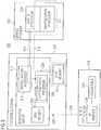
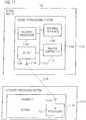
- Figure 1illustrates one embodiment of a system 100 where selected services may be provided to a user via a computing device only when a wireless token assigned to a user is proximate to the computing device. Operations of the system 100 will be explained in more detail in conjunction with the flowchart of Figure 2 .
- an access device 102such as a computer includes components that may be used to determine whether a wireless token 104 assigned to a user or users is proximate to the access device 102.
- a wireless proximity reader 106may be configured to receive signals 108 (e.g., RF signals) from the wireless proximity token 104.
- the signals 108may include information that uniquely identifies the wireless proximity token 104.
- this informationmay include one or more credentials (e.g., a password) that may be used to access a secured service provided by a service provider 110.
- the determination of proximity between the token 104 and the reader 106may be established using a variety of mechanisms depending on the application.
- the tokenwill not generate signals until it is within a given distance of the reader. This may be accomplished, for example, by using a relatively passive token that intercepts signals transmitted by the reader and transmits signals in response to the received signals. Different distances between the token 104 and the reader 106 may be defined as indicative of proximity depending on the requirements of the application and, in some cases, characteristics of the operating environment.
- the access device 102may request access to a service from the service provider 110 by sending a signal over a communication media 112.
- the communication media 112may comprise, for example, electric wires, optical cables or air.
- access to the servicewill be initiated by the user's interaction with the access device 102.
- the usermay use a keyboard or pointing device (e.g., a computer mouse) to request the service.
- a keyboard or pointing devicee.g., a computer mouse
- the usermay be asked to input a password and/or provide a biometric (e.g., a fingerprint) to a biometric reader to further verify the authenticity of the user.
- a biometrice.g., a fingerprint
- access to a servicemay be restricted until the user satisfies one or more verification queries including, for example, what the user knows (e.g., a password), what the user possesses (e.g., a token) and who the user is (e.g., a physical or biometric characteristic).
- the access device 102may automatically request a predefined service once the user places the token 104 proximate the access device 102.
- the access device 102may include a database (not shown) that matches a given token (or information from the token) with one or more default services.
- the access device 102may automatically request the services from the service provider 110.
- the access device 102may send authentication-related information to the service provider 110 to indicate that the token 104 is proximate to the access device 102.
- the access device 102may include an authentication component 116 such that the determination of whether the token 104 is proximate the access device 102 is performed in a secure manner.
- the information provided by the tokenmay be maintained within the access device 102 in a secure manner. For example, the information may only pass between the reader 106 and the authentication component 114 via a connection 116 within a common integrated circuit.
- the authentication component 114may be in secure communication with the service provider 110. This may be accomplished, for example, by placing the authentication component 114 and the service provider 110 on the same integrated circuit or within secured hardware. In addition, a cryptographically secured communication channel may be established between the authentication component 114 and the service provider 110.
- the authentication informationmay include information from the token.
- the authentication component 114may process (e.g., encrypt or sign) the information before sending it to the service provider 110. Since communications from the access device 102 may be trusted in this example, the authentication component 114 thereby provides a cryptographically reliable authentication that the information is from a specific token that is proximate that particular access device. In other words the encryption or cryptographic signing of the information may provide the necessary authentication.
- the service provider 110may then enable access to the requested service (block 208). This process may involve verifying that the information sent from the token 104 includes a credential associated with an authorized user and or access device.
- a servicemay include, for example, access to data and/or a data processing service.
- a servicemay enable an access device to, for example, read or write data in a data memory, access encrypted data, use cryptographic keys, gain access to cryptographic material such as security associations and keys, access a web page, access a data network or access a processing application.
- datamay include any information that may be accessed by a computing device including, for example, data files, passwords and cryptographic security associations including keys.
- accessmay include, for example, acquiring, using, invoking, etc.
- datamay be accessed by providing a copy of the data to the access device.
- Dataalso may be accessed by enabling the access device to manipulate or use the data.
- a trusted platform modulemay use keys to perform operations for the user.
- accessmay include, for example, sending and/or receiving data over the network.
- processing application accessmay include, for example, invoking, interacting with or using the application or loading the application onto the access device.
- a service providermay comprise hardware and/or software that facilitate providing a service.
- a service providermay consist of a processing system that processes requests for service, verifies whether the requester is authorized to access the service and provides or facilitates the requested access.
- a service providermay be located local or remote with respect to the entity requesting service (e.g., access device 102).
- a local trusted platform modulemay control access to passwords in a computing system and a remote wireless access point may control a computing system's access to a data network connected to the access point.
- An access devicemay comprise hardware and/or software that facilitate access to a service.
- a service providermay comprise a computing system such as, without limitation, a personal computer, a server, a cellular phone, a personal data assistant ("PDA”), etc.
- PDApersonal data assistant
- Figure 1only depicts one token, access device and service provider. It should be understood, however, that a system may include any number of these components.
- a usermay use a token to access one or more services via one or more access devices.
- an access devicemay access services from multiple service providers.
- multiple access devicesmay access the services provided by a given service provider.
- Authorization to access a servicemay depend on the specific token and access device being used. For example, a user may be assigned one token to access certain services through certain access devices. In addition, the user may be assigned another token to access other services through the same or other devices. Also, multiple sets of information (e.g., credentials) may be included on a single token to enable a user to access different services or to enable multiple users to share a token.
- a wireless proximity reader and tokenmay be implemented using one or more of a wide variety of wireless proximity techniques.
- the proximity reader and the tokenmay support, without limitation, one or more of RFID, ISO 14443 and ISO 15693.
- Tokensmay be implemented in various physical forms depending upon the needs of the respective applications.
- a tokenmay be in a form that is easy to carry, similar to a plastic credit card, a "smart card” or a building access card.
- a tokenmay take the form of a tag or a label that may be attached to another article.
- tokensmay include, without limitation, smart cards, credit cards, dongles, badges, biometric devices such as fingerprint readers, mobile devices such as cellular telephones, PDAs, etc.
- the tokenincludes circuitry used in a typical smart card.
- the tokenmay store an encrypted password that may be sent to an authentication system.
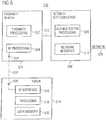
- Figure 3depicts one embodiment of a proximity-based authentication system 300 where a processing system 302 is used to access services provided by a service provider 304.
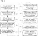
- Figure 4describes several proximity-based authentication operations.
- a security boundaryis provided within the processing system 302 to, for example, secure the process of gaining access to a service, including securing the authentication process and information used during the authentication process.
- This security boundarymay be established, for example, using hardware and/or cryptographic techniques.
- Hardware techniques for providing a security boundarymay include, for example, placing components within a single integrated circuit.
- an RFID reader 306, a cryptographic processor 308 and a service access processor 310may be incorporated into a single integrated circuit 312.
- any processes performed or information used or stored within the integrated circuit 312may not be compromised absent physical access to the integrated circuit 310 and the use of an invasive technique for analyzing the internal operations and data of the integrated circuit 312.
- this form of hardware security boundarymay provide an acceptably high level of security.
- one or more integrated circuitsmay be protected by a physical structure using known techniques (e.g., epoxy encapsulation).
- the processing system 302 and/or its internal componentsmay be tamper resistant and/or tamper evident.
- Cryptographic techniques for providing a security boundarymay include encrypting any important information that is sent to or from the integrated circuit via non-secure paths in the system. For example, security associations and keys may only appear in the clear within the integrated circuit 312. In the event keys need to be sent out of the integrated circuit 312 (e.g., to be stored in a data memory 314), the keys may first be encrypted.
- any important information that is sent between the integrated circuit 312 and the service provider 304may be encrypted.
- informatione.g., credentials 328
- an RFID token 316may be encrypted before being sent to the service provider 302.
- a cryptographic security boundaryis represented by the dashed line 318.
- the line 318represents, in part, that encrypted information may be sent between the cryptographic processor 308, the service access processor 310 and the data memory 314.
- the informationmay be sent securely even though the mechanism through which this information is sent (e.g., a data bus 320) may not be secure.
- Encrypted informationalso may be sent between the integrated circuit 312 and a cryptographic processor 322 and a service processor 324 in the service provider 304 via a communication link 326.
- the cryptographic processors 308 and 322may perform key exchange and encryption, decryption and/or authentication operations necessary to send and receive the encrypted information and provide the information in the clear for internal processing.
- the form of protection provided within the systemmay depend on the requirements of a given application.
- specifications such as FIPS-140-2define various levels of security that may be implemented within a system
- the security boundary provided by the integrated circuit 312 and the cryptographic boundary 318may be used to provide a secure mechanism for authenticating a user to access a service.
- credentials 328 received from the RFID token 316may be provided directly into the integrated circuit 312 via RF signals 338
- the credentials 328need not be entered into the processing system 302 via a software mechanism or hardware that is accessible by software. Consequently, such information may not be compromised by hacking or a software virus at this stage of the process.
- the informationmay be protected by the physical boundary of the integrated circuit 312 and by the cryptographic boundary 318. For example, provisions may be made to ensure that the information does not appear in the clear outside of the integrated circuit 312. Thus even if rogue software in the processing system 302 were to gain access to the information outside of the chip 312, the software would not be able to decrypt it without appropriate key information.
- the key informationalso may be protected within the integrated circuit 312 and the cryptographic boundary 318. That is, the key information may not appear in the clear outside of the security boundary. As a result, the credentials may be securely routed to the service provider 304.
- the processing system 302may reliably authenticate to the service provider 304 that a specific RFID token 316 is proximate the processing system 302.
- the credentialsmay be received in a secure manner.
- the effective "decision" as to whether the token 316 is adjacentmay be made within the security boundary.
- the cryptographic processor 308may then cryptographically sign this information using a secure protocol set up between the cryptographic processors 308 and 322 of the processing system 302 and the service provider 304, respectively. Via this signature the service provider 304 may be assured that a given message came from a specific processing system (e.g., processing system 302) and that the message has not been compromised. Accordingly, proximity of the token 316 to the processing system 302 may be used as a reliable method of authorizing access to a secured service provided by the service provider 304.
- the processing system 302may request access to a service provided by the service provider 304. As discussed above this access request may be initiated automatically or as a result of user input.
- the service provider 304may issue a challenge in response to the request (block 406).
- the service processor 324may request credentials such as a password. Inherent or explicit in this challenge may be a requirement that the user's token be proximate to the device that requested access (e.g., the processing system 302).
- the RFID reader 306will receive an RFID signal 338 from the RFID token 316.
- the RFID signal 338may be received by the processing system 302 within a security boundary.
- the RFID reader 306generates RF signals that are broadcast via an antenna 332.
- an RF signal(e.g., as represented by line 338) may be received by an antenna 334 and processed by an RF interface 336 in the token 316.
- the reader and the tokenmay designed to communicate with one another when they are within a predefined distance of each other.
- the received RF signalmay be used to power and activate the token 316.
- the token 316may include circuitry that extracts energy from the received RF signal and converts this energy into power for the components on the token 316.
- the token 316may include circuitry that stores information such as the credentials 328 discussed herein.
- authentication informationsuch as network authentication credentials, passwords and/or certificates may be stored in a data memory (e.g., a non-volatile memory) on the token 316.
- the RF interface 336may generate an RFID signal that is broadcast by the antenna 334. Circuitry in the token 316 may be configured to modulate this RFID signal so that it includes some or all of the information stored on the token 316.
- the broadcast RFID signal(e.g., as represented by line 330) may then be received by the antenna 332 and sent to the RFID reader 306.
- the system 300may be configured so that any information contained within the broadcast RFID signal may be extracted only within a security boundary.
- the RDIF reader 306 that extracts the information from the RFID signal 330may be located within an integrated circuit that includes other functionality to protect the information.
- the integrated circuit 312may include a cryptographic processor 308 that encrypts the information (block 412) to prevent the information from being sent out of the integrated circuit 312 in the clear.
- this encryption process and/or another cryptographic processmay be used to cryptographically sign the information.
- the cryptographic processor 308may use a private key to encrypt the information.
- a public key associated with this private keymay be published with a certificate from a trusted entity. This certificate serves to verify that the public key is authentic.
- the cryptographic processor 322may then use the public key to decrypt any encrypted information received from the cryptographic processor 308.
- a complementary processmay be used to securely send information in the other direction across the link 326.
- the service access processor 310sends the signed information to the service processor 324 via the link 326 (block 416).
- the informationis, in effect, sent over a secured channel (as represented by the corresponding portion of the line 318) even though the actual data path may not be secure.
- the service processor 324then sends the received information to the cryptographic processor 322 for decryption and/or authentication processing as necessary.
- the service processor 324then verifies that the received information indicates that the user is authorized to access the requested service (block 418). In conjunction with this process, the service processor 324 has received an indication via the cryptographic signature associated with the information that the token 316 is proximate the processing system 302.
- the service processor 324may then provide access to the requested service. As discussed above, this may involve a variety of operations depending on the particular service requested. For example, if the service provider 304 is a key manager, the service may involve providing security associations or keys to the processing system. As discussed above, these keys may be sent to the processing system 302 via the secured channel (cryptographic boundary 318). In addition, the processing system 302 may be configured so that these keys, etc., are maintained within a security boundary.
- a wireless proximity and authentication systemthat controls access to one or more data networks.
- These systemsmay enable a user to use a device to access, for example, one or more wired or wireless networks after the system verifies that the user (e.g., the user's token) is relatively close to the device. In this way, a reasonable inference may be made that an authorized user (as opposed to an unauthorized user or code) is attempting to access the network(s).
- a communication system 500includes a proximity reader 501, one or more network authentication components 506 and a wireless proximity token 514.
- a userTo access a particular data network 528 a user (not shown) initiates a connection and/or authentication process via authentication processing 508 in a corresponding network authentication component 506.
- the usermay bring the token 514 in relatively close physical proximity to the proximity reader 501.
- the proximity reader 501may then receive appropriate authentication information from the token 514 and forward the authentication information to the network authentication component 506.
- the authentication processing 508uses this authentication information to respond to the network's challenge.
- the usermay be granted access to the data network 528. This process may then be repeated using different network authentication components to gain access to additional networks, if desired.
- the proximity reader 501 and the token 514communicate via RF signals as represented by dashed line 522.
- a proximity processing component 502controls RF processing 504 in the proximity reader 501 to generate RF signals that are broadcast via an antenna 524.
- the signalsmay be received by an antenna 526 and processed by an RF interface 516.
- the received RF signalsmay be used to power and activate the token 514.
- the RF interface 516may generate RF signals that are sent back to the RF processing 504.
- the proximity processing component 502may then process the received signals to verify that a particular token is within range.
- the proximity processing component 502may process the information received from the token 514 before passing the information to the network authentication component 506.
- the token 514may include circuitry that provides the authentication information and proximity signaling.
- authentication informationsuch as network authentication credentials, passwords and/or certificates may be stored in a data memory 520 on the token. In some embodiments some or all of this authentication information may be encrypted.
- the token 514may include a processing component 518 that controls communication with the proximity reader 501.
- the processing component 518may enable the token 514 to be programmed with the authentication information.
- the processing component 518may process RF signals received from the proximity reader 501 to power and activate the token 514. Also, the processing component 518 may control the generation of appropriate signals to send the authentication information to the proximity reader 501.
- the network authentication component 506may connect to one or more of a variety of networks.
- the network 528may comprise a wired or wireless network.
- the network interface 510provides appropriate hardware and/or software to connect to such a network.
- the network interfacecomprises a media access controller ("MAC") .
- the systemmay be used to access one or more wired networks including, without limitation, personal area networks (“PANs”), local area networks (“LANs”) and wide area networks (“WANs”).
- PANspersonal area networks
- LANslocal area networks
- WANswide area networks
- These networksmay support a variety of protocols including, without limitation, Ethernet-based protocols.
- the wireless network(s)may be implemented using one or more of a wide variety of wireless solutions.
- a wireless networkmay comprise, without limitation, cellular telephone networks such as Global System for Mobile communications ("GSM”) and General Packet Radio Service (“GPRS”), wireless local area networks such as 802.11a, 802.11b and/or 802.11g (referred to herein for convenience as simply 802.11) and personal area networks such as Bluetooth.
- GSMGlobal System for Mobile communications
- GPRSGeneral Packet Radio Service
- 802.11a, 802.11b and/or 802.11greferred to herein for convenience as simply 802.11
- personal area networkssuch as Bluetooth
- a wireless network interfacemay comprise a media access controller that supports one or more of these networks.
- multiple wireless network interfacesmay be used to provide connectivity to several wireless networks (e.g., 802.11 and Bluetooth).
- Figure 6depicts an integrated wireless proximity apparatus and wireless communications system 600 that provides wireless communication access using proof of proximity for authentication purposes.
- a usermay use a mobile device 601 (e.g., a desktop personal computer, a laptop computer, a cellular phone, a PDA, etc.) to access one or more wireless networks (e.g., a cellular network, an 802.11 network, a Bluetooth network, etc.).
- a mobile device 601e.g., a desktop personal computer, a laptop computer, a cellular phone, a PDA, etc.
- wireless networkse.g., a cellular network, an 802.11 network, a Bluetooth network, etc.
- the usermay use the token 618 in a similar manner as discussed above to quickly and securely access the wireless network.
- access to the wireless networkmay be provided when a user moves the token 618 within relatively close proximity (e.g., as may be defined in the proximity standards listed above) to the reader 604.
- the tokenthen sends authentication information to the proximity reader 604 via RF signals 620.
- the proximity reader 604may, in turn, send authentication information to one or more wireless network interface(s) 606.
- Each network interface 606may perform network authentication and connection processing to enable communication with a given wireless network. This may involve, for example, communicating with a respective access controller 610 in one or more access point (s) 608 via RF signals 612 transmitted and received via one or more antennas 614 and 616.
- Figure 6also illustrates that a wireless proximity apparatus and a wireless communications system may be integrated into a single integrated circuit (e.g., "chip") 602.
- the proximity reader 604 and one or more wireless network interface(s) 606are implemented within the chip 602.
- sensitive informationsuch as the authentication information from the token is not exposed in the mobile device outside the chip 602. Rather, these signals are sent between the proximity reader 604 and the network interface 606 via internal leads 622 in the chip 602. Accordingly, this information may be maintained within a security boundary as discussed herein.
- the authentication informationmay be passed between these components via conventional software message processing. If such a computer is compromised, the authentication information may be intercepted by unauthorized persons or code.
- the network authentication component 506 and/or the mobile device 601may be referred to as an access device in the discussion that follows.
- the systemmay be configured to provide a security boundary as discussed herein.
- a proximity reader 604 and one or more wireless network interface(s) 606may be incorporated into a single integrated circuit 602.
- information from the token 618may be securely used within the mobile device 601 by, for example, not allowing the information to leave the integrated circuit 602 in the clear.
- a wireless connectionis used to communicate with one or more access point(s) 608, the information may only appear within RF signals outside of the integrated circuit 602.
- cryptographic techniques as discussed hereinmay be used to provide a security boundary for the information.
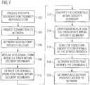
- the access systemmay request a connection to a network via a corresponding network access provider (e.g., access point 608).
- a corresponding network access providere.g., access point 608
- this requestmay be initiated automatically or as a result of user input.
- the network access providermay issue a challenge in response to the request (block 706).
- a network access pointmay request a credential such as a password.
- Inherent or explicit in this challengemay be a requirement that the user's token be proximate to the access device.
- the proximity readere.g., proximity reader 501 or 604 will receive an RF signal (e.g., an RFID signal) from the token.
- the RF signalmay be received within the security boundary of the access device.
- the systemmay be configured so that any information contained within the broadcast RF signal may be extracted only within a security boundary. This may be accomplished, for example, using some of the techniques discussed herein.
- a cryptographic processmay be used to cryptographically encrypt/sign the information. After the information is signed by the cryptographic process, the access device sends the signed information to the network access provider (e.g., access point 608) as represented by block 716.
- the network access providere.g., access point 608
- the network access providerAfter verifying that the credentials are associated with an authorized user at block 718, the network access provider provides access to the requested network.
- security processing systemsi.e., key management systems
- These systemsmay enable a user to access, for example, services controlled by a security processing system on a computer.
- servicemay be provided after the system verifies that the user (e.g., the user's token) is relatively close to the computer.
- a security processing systemprovides key management functions such as generating keys, setting policy (e.g., capabilities and security limits) for keys and using keys in accordance with the corresponding policy (e.g., using the keys securely).
- a security processing systemmay implement key backup and recovery, prepare keys for storage, provide key revocation and destruction, provide multiple layers of security and provide other key management functions.
- Key management functionsmay involve authorized key usage such as smart card K of N access control or a key may be linked to a particular user, application, etc.
- Key management functionsmay involve secure audit logs such as tracking key usage to provide an audit trail.
- FIG 8depicts one embodiment of computing system 800 that incorporates a proximity reader 806 and a security processing system implemented as a trusted platform module (“TPM”) 802.
- TPMtrusted platform module
- This embodimentmay be used to authenticate access to data networks or other data services in a similar manner as discussed above.
- a usermay access a wired data network 820 or the user may access encrypted data stored in data files 824 (e.g., data memory).
- a TPMmay provide a set of cryptographic capabilities that enable certain computer functions to be securely executed within the TPM environment (e.g., hardware). Specifications for a TPM are defined by the Trusted Computing Group organization. As shown in Figure 8 , a TPM 802 (e.g., a TPM integrated circuit) may be incorporated into a computer.
- the TPM 802includes a master controller 808 for controlling the overall operation of the TPM, an external interface 810 for interfacing with other components in the computer and a security processor 804.
- the security processor 804may perform cryptographic operations including, for example, encryption, decryption, authentication and key management. In the embodiment of Figure 8 , these components communicate via a bus 812.
- authorization informationis stored on the token 816.
- the tokenmay store authorization data such a 100 bit encrypted password.
- the usermay use the token 816 (and in some applications, other information or biometrics as discussed above) to authenticate himself or herself to the TPM 802.
- network authentication credentialsmay be stored in a data memory (not shown) in the TPM 802.
- the TPM 802may use these credentials to authenticate itself to an associated network and/or service provider.
- the userwhen a user wishes to access a service provided by the TPM 804, the user brings the token 816 in relatively close proximity with the computer 801 (block 902). In this way the user may authenticate himself or herself to the TPM 802.
- the proximity reader 806 in the TPM 802receives the RF signals 814 from the token 816 and extracts any embedded information such as the user's credentials (block 906). After verifying the information (block 908), the TPM 802 may provide the requested access or may facilitate acquiring access to a service from another processing entity (block 910).
- the system of Figure 8may be used to access encrypted data (e.g., an encrypted password) stored in a local data memory 824.
- the TPM 802may store cryptographic information (e.g., keys, security associations, etc.) that enables the TPM to decrypt encrypted data.
- encrypted data files 824may be accessed via other components (e.g., a file manager 822) in the computer 801. The security of the encrypted data may be maintained in such components outside the TPM since decryption may be restricted to occur only within the TPM. In other words, sensitive information that is in the clear is not allowed to leave the secure boundary provided by the TPM 802.
- the TPM 802may provide the information to a service provider connected to a network 820.
- the TPM 802may send information such as network authentication credentials to one or more network access devices (not shown) via one or more network interfaces 818 to enable the user to gain access to one or more networks 820.
- sensitive informationsuch as the authentication information from the token is securely maintained in the computer inside the TPM. In a manner similar to that discussed above, this information may be provided directly to the TPM via the RF signal 814.
- the authentication informationmay be passed between these components via the software stack. In this case, if the stack is compromised, the authentication information may be compromised as well.
- the network interface (s) 818may be used to connect to wired and/or wireless network(s) 820. As discussed herein, cryptographic techniques may be used to ensure the security of data transferred between the TPM 802 and other devices connected to a network 820. Accordingly, a network connection may be used, for example, to communicate with a key manager to obtain key information (e.g., security associations) and authorization for key usage.
- key informatione.g., security associations
- a TPM 1002a proximity reader 1004 and one or more network interfaces (e.g., interface(s) 606 in Figure 6 ) 1006 may be combined on a single integrated circuit 1000. In this way, sensitive information may be maintained within a security boundary defined by the chip 1000.
- the combination of these components within a single chipmay reduce the cost of the system. For example, by providing all of these components within a single CMOS integrated circuit the per chip cost of these components may be relatively small. As a result, it may be cost effective to provide the features discussed herein into a mobile device.
- the embodiment of Figure 10may be advantageous when the network interface(s) provides connectivity to wireless network(s).
- sensitive informatione.g., credentials, passwords, keys, etc.
- thismay provide a relatively inexpensive and secure path directly to the TPM 1002 for authorization of key usage.
- the computermay comprise a point-of-sale device. That is, the token 816 (e.g., a token with smart card functionality) may provide the user's credit card information to the computer 801 and the computer 801 could securely receive and verify this information to perform a sales transaction.
- the token 816e.g., a token with smart card functionality
- FIG 11depicts one embodiment of a system 1100 where a mobile device 1101 may be used to authenticate a user to another processing system (e.g., one that includes a security processing system 1124 such as a TPM).
- the mobile device 1101includes a security processing system 1102 (e.g., a TPM) that in turn includes an RFID client 1106.
- the security processing systeme.g., TPM
- the security processing systemmay include, for example, a security processor 1104, a master controller 1110 and an external interface 1108 that communicate via an internal bus 1112.
- An RF signal 1116 transmitted by an antenna 1114may then be received by a nearby proximity reader 1120 via an antenna 1118.
- the mobile device 1101e.g., a laptop computer, a PDA, a cellular phone, etc.
- the security processing system 1102may store credit card information that may be sent to an RF processing component 1122 in a proximity reader 1120 in the security processing system 1124. Once this information is within the security boundary provided by the security processing system 1124, the information may be used, for example, by point-of-sale components (not shown) associated with the security processing system 1124 to access data services (e.g., perform a sales transaction).
- a wireless proximity and authentication systemmay be used to securely and efficiently access one or more data service(s) that may be associated with a variety of applications.
- applicationsmay include, without limitation, authentication applications relating to network access (RSA token), processing of biometrics, credit card transactions, and voice over Internet Protocol (“VoIP").
- RSA tokenauthentication applications relating to network access
- biometricsprocessing of biometrics
- credit card transactionscredit card transactions
- VoIPvoice over Internet Protocol
- Different embodiments of the inventionmay include a variety of hardware and software processing components.
- hardware componentssuch as controllers, state machines and/or logic are used in a system constructed in accordance with the invention.
- codesuch as software or firmware executing on one or more processing devices may be used to implement one or more of the described operations.
- Such componentsmay be implemented on one or more integrated circuits. For example, in some embodiments several of these components may be combined within a single integrated circuit. In some embodiments some of the components may be implemented as a single integrated circuit. In some embodiments some components may be implemented as several integrated circuits.
- connections represented by the lead lines in the drawingsmay be in an integrated circuit, on a circuit board and/or over a backplane to other circuit boards.
- some of the connections represented by the lead lines in the drawingsmay comprise a data network, for example, a local network and/or a wide area network (e.g., the Internet).
- a signalmay be an electrical signal transmitted over a wire, light pulses transmitted over an optical fiber or electromagnetic (e.g., RF or infrared) radiation transmitter through the air.
- electromagnetice.g., RF or infrared
- a signalmay comprise more than one signal.
- a signalmay consist of a series of signals.
- a differential signalcomprises two complementary signals or some other combination of signals.
- a group of signalsmay be collectively referred to herein as a signal.
- Signals as discussed hereinalso may take the form of data.
- an application programmay send a signal to another application program.
- Such a signalmay be stored in a data memory.
- a data memorymay comprise Flash memory, one-time-programmable (OTP) memory or other types of data storage devices.
- OTPone-time-programmable
- the components and functions described hereinmay be connected/coupled directly or indirectly. Thus, in some embodiments there may or may not be intervening devices (e.g., buffers) between connected/coupled components.
- intervening devicese.g., buffers
Landscapes
- Engineering & Computer Science (AREA)
- Computer Networks & Wireless Communication (AREA)
- Computer Security & Cryptography (AREA)
- Signal Processing (AREA)
- Computer Hardware Design (AREA)
- General Engineering & Computer Science (AREA)
- Computing Systems (AREA)
- General Physics & Mathematics (AREA)
- Physics & Mathematics (AREA)
- Theoretical Computer Science (AREA)
- Business, Economics & Management (AREA)
- Software Systems (AREA)
- Health & Medical Sciences (AREA)
- Biomedical Technology (AREA)
- General Health & Medical Sciences (AREA)
- Accounting & Taxation (AREA)
- Strategic Management (AREA)
- General Business, Economics & Management (AREA)
- Mobile Radio Communication Systems (AREA)
- Lock And Its Accessories (AREA)
Description
- This application relates to data communication systems and, more specifically, to techniques for authenticating proximity of a wireless token in a communication system.
- A variety of security techniques are known for protecting information in and controlling the operation of a computing device such as a personal computer ("PC"), a server or a mobile device. For example, physical and/or cryptographic techniques may be employed to control access to the computing device and to data stored in the computing device.
Physical security techniques may include locating the computing device in a secure location, locking the computing device in an enclosure, protecting integrated circuits (i.e., chips) from invasive monitoring by encapsulating the chips in, for example, an epoxy.
Cryptographic techniques may include one or more of encryption, decryption, authentication, signing and verification. In some applications data encryption and decryption techniques may be used to prevent unauthorized applications or persons from accessing data stored in the computing device. For example, security passwords that are used to restrict access a PC may be stored on the PC in an encrypted form. The operating system may then decrypt password when it needs to compare it with a password typed in by a user. - In some applications authentication techniques may be used to verify that a given set of data is authentic. For example, when a server receives a message from a remote client, authentication information associated with the message may used to verify that the message is from a specific source. In this way, the server may ensure that only authorized clients access the applications and data provided by the server.
- In practice, there may be circumstances under which the process of sending secret credentials such as a password or cryptographic key may be compromised. For example, when a user uses a computing device to access a secured service, the user may first need to enter the secret credentials into the computing device. The computing device may then forward these credentials to a service provider that then determines whether the user is authorized to use the requested service.
- In the event the computing device has been comprised by a hacker or a computer virus, an unauthorized person may gain access to these credentials. As a result, an unauthorized person may be able to access the secured service. Serious consequences may result when the secured service includes sensitive information such as financial data or personal information. Accordingly, a need exists for improved techniques for providing access to secured services.
US 2003/0097586 A1 describes a security system for facilitating transponder carrier identification and tracking within a secure area comprising: an RF transponder having a memory in which is stored a unique identifier; and a transponder writer operable to send a replacement unique identifier to the transponder, the transponder replacing the identifier in the transponder memory with the replacement identifier. A corresponding transponder, transponder reader and method of identity verification are also described.US6092202 A describes a method and system comprising a security co-processor and an interface for interfacing the security co-processor to a host computer system. The method and system wherein secure transaction processing is performed locally in the security co-processor and non-secure transaction processing is performed in the host computer system.- The invention relates to a system and method for authenticating the proximity of a wireless token to a computing device as defined by
claim 1 and claim 12, respectively. Dependent claims constitute embodiments of the invention. The embodiments of the following description which are not covered by the appended claims are considered as not being part of the present invention. - In one aspect, the invention relates to a system and method for providing access to a secured service based on a user's proximity to a proximity reader. Once the proximity is authenticated the user may then be allowed to access the secured service.
- In some embodiments an authorized user is provided access to a service only when a wireless token assigned to the user is in the proximity of a computing device through which access to the secured services is obtained. In this way, a reasonable assumption may be made that the authorized user is in fact using the computing device to request the service. In contrast, if the request was being made by a hacker or a computer virus, access may be denied since the token may not be in the proximity of the computing device.
- In the invention a user's credential are stored on an RFID token and an RFID reader is implemented within a security boundary on the computing device. In this way, the credential may be passed to the security boundary without passing through the computing device via software messages or applications. As a result, the credentials may not be intercepted by a hacker or computer virus that may have compromised the software executing on the computing system.
- In some embodiments the security boundary may be provided, in part, using tamper resistant and/or tamper evident hardware. Thus, in the event the computer was physically tampered with in an attempt to compromise the security of the security boundary, such tampering may be ineffective or it may be evident to the user. In the latter case, the user may then take appropriate steps to re-secure the system.
- In the invention, the RFID reader is incorporated onto the same chip as a cryptographic processing component. In this way, once the information from the RFID token is received by the RFID reader it may be encrypted within the chip. As a result, the information may never be presented in the clear (e.g., unencrypted) outside of the chip. Accordingly, the information may only be compromised by a clandestine RFID reader or by inspecting the internal contents of the chip. In conventional commercial settings, these scenarios may be unlikely. Accordingly, a system constructed according to the invention may provide improved access control for secured services.
- In the invention, a cryptographic processing component may cryptographically encrypt and/or sign credentials received from a token. Thus, when a service provider receives the credentials, a high level of assurance may be provided to the effect that the credentials came from a token that was proximate to the particular computing device.
- In some embodiments an RFID reader, a cryptographic processing component and one or more wireless network controller(s) may be implemented on a single chip in a mobile device. This may provide a cost effective and secure mechanism to limit access to the wireless network(s). In this case, network access may only be provided to the mobile device when a token is proximate to the mobile device and when that token has been assigned to an authorized user of that mobile device and the network(s).
- These and other features, aspects and advantages of the present invention will be more fully understood when considered with respect to the following detailed description, appended claims and accompanying drawings, wherein:
FIG. 1 is a simplified block diagram of one embodiment of a proximity-based authentication system constructed in accordance with the invention;FIG. 2 is a flow chart of one embodiment of proximity-based authentication operations that may be performed in accordance with the invention;FIG. 3 is a simplified block diagram of one embodiment of a proximity-based authentication system constructed in accordance with the invention;FIG. 4 is a flow chart of one embodiment of proximity-based authentication operations that may be performed in accordance with the invention;FIG. 5 is a simplified block diagram of one embodiment of a proximity-based network authentication system constructed in accordance with the invention;FIG. 6 is a simplified block diagram of one embodiment of a proximity-based wireless network authentication system constructed in accordance with the invention;FIG. 7 is a flow chart of one embodiment of proximity-based network authentication operations that may be performed in accordance with the invention;FIG. 8 is a simplified block diagram of one embodiment of proximity-based authentication for a trusted platform module constructed in accordance with the invention;FIG. 9 is a flow chart of one embodiment of proximity-based authentication operations for a trusted platform module that may be performed in accordance with the invention;FIG. 10 is a simplified block diagram of one embodiment of an integrated circuit including a trusted platform module constructed in accordance with the invention; andFIG. 11 is a simplified block diagram of one embodiment of proximity-based authentication for a trusted platform module constructed in accordance with the invention.- In accordance with common practice the various features illustrated in the drawings may not be drawn to scale. Accordingly, the dimensions of the various features may be arbitrarily expanded or reduced for clarity. In addition, some of the drawings may be simplified for clarity. Thus, the drawings may not depict all of the components of a given apparatus or method. Finally, like reference numerals denote like features throughout the specification and figures.
- The invention is described below, with reference to detailed illustrative embodiments. It will be apparent that the invention may be embodied in a wide variety of forms, some of which may be quite different from those of the disclosed embodiments. Consequently, the specific structural and functional details disclosed herein are merely representative and do not limit the scope of the invention.
Figure 1 illustrates one embodiment of asystem 100 where selected services may be provided to a user via a computing device only when a wireless token assigned to a user is proximate to the computing device. Operations of thesystem 100 will be explained in more detail in conjunction with the flowchart ofFigure 2 .- As represented by
block 202 inFigure 2 an access device 102 (Figure 1 ) such as a computer includes components that may be used to determine whether awireless token 104 assigned to a user or users is proximate to theaccess device 102. For example, awireless proximity reader 106 may be configured to receive signals 108 (e.g., RF signals) from thewireless proximity token 104. Thesignals 108 may include information that uniquely identifies thewireless proximity token 104. In addition, this information may include one or more credentials (e.g., a password) that may be used to access a secured service provided by aservice provider 110. - The determination of proximity between the token 104 and the
reader 106 may be established using a variety of mechanisms depending on the application. In some embodiments, the token will not generate signals until it is within a given distance of the reader. This may be accomplished, for example, by using a relatively passive token that intercepts signals transmitted by the reader and transmits signals in response to the received signals. Different distances between the token 104 and thereader 106 may be defined as indicative of proximity depending on the requirements of the application and, in some cases, characteristics of the operating environment. - As represented by
block 204, theaccess device 102 may request access to a service from theservice provider 110 by sending a signal over acommunication media 112. Depending upon the particular application, thecommunication media 112 may comprise, for example, electric wires, optical cables or air. - Typically, access to the service will be initiated by the user's interaction with the
access device 102. For example, the user may use a keyboard or pointing device (e.g., a computer mouse) to request the service. In conjunction with this the user may be asked to input a password and/or provide a biometric (e.g., a fingerprint) to a biometric reader to further verify the authenticity of the user. In this way, access to a service may be restricted until the user satisfies one or more verification queries including, for example, what the user knows (e.g., a password), what the user possesses (e.g., a token) and who the user is (e.g., a physical or biometric characteristic). - In some embodiments, the
access device 102 may automatically request a predefined service once the user places the token 104 proximate theaccess device 102. For example, theaccess device 102 may include a database (not shown) that matches a given token (or information from the token) with one or more default services. Thus, when a token associated with default services approaches theaccess device 102, theaccess device 102 may automatically request the services from theservice provider 110. - As represented by
block 206, theaccess device 102 may send authentication-related information to theservice provider 110 to indicate that the token 104 is proximate to theaccess device 102. For example, theaccess device 102 may include anauthentication component 116 such that the determination of whether the token 104 is proximate theaccess device 102 is performed in a secure manner. In addition, the information provided by the token may be maintained within theaccess device 102 in a secure manner. For example, the information may only pass between thereader 106 and theauthentication component 114 via aconnection 116 within a common integrated circuit. - In addition, the
authentication component 114 may be in secure communication with theservice provider 110. This may be accomplished, for example, by placing theauthentication component 114 and theservice provider 110 on the same integrated circuit or within secured hardware. In addition, a cryptographically secured communication channel may be established between theauthentication component 114 and theservice provider 110. - In some embodiments, the authentication information may include information from the token. In the case where the communications over the
media 112 may be cryptographically secured, theauthentication component 114 may process (e.g., encrypt or sign) the information before sending it to theservice provider 110. Since communications from theaccess device 102 may be trusted in this example, theauthentication component 114 thereby provides a cryptographically reliable authentication that the information is from a specific token that is proximate that particular access device. In other words the encryption or cryptographic signing of the information may provide the necessary authentication. - After the
service provider 110 has received an authenticated indication that the token is proximate theaccess device 102, theservice provider 110 may then enable access to the requested service (block 208). This process may involve verifying that the information sent from the token 104 includes a credential associated with an authorized user and or access device. - As used herein the term service may include, for example, access to data and/or a data processing service. Thus, a service may enable an access device to, for example, read or write data in a data memory, access encrypted data, use cryptographic keys, gain access to cryptographic material such as security associations and keys, access a web page, access a data network or access a processing application.
- As used herein the term data may include any information that may be accessed by a computing device including, for example, data files, passwords and cryptographic security associations including keys.
- As used herein the term access may include, for example, acquiring, using, invoking, etc. Thus, data may be accessed by providing a copy of the data to the access device. Data also may be accessed by enabling the access device to manipulate or use the data. As an example of the latter, once a user has been authorized to access a service a trusted platform module may use keys to perform operations for the user. For a data network, access may include, for example, sending and/or receiving data over the network. For a processing application access may include, for example, invoking, interacting with or using the application or loading the application onto the access device.
- A service provider may comprise hardware and/or software that facilitate providing a service. For example, a service provider may consist of a processing system that processes requests for service, verifies whether the requester is authorized to access the service and provides or facilitates the requested access.
- In practice, a service provider (e.g., service provider 110) may be located local or remote with respect to the entity requesting service (e.g., access device 102). For example, a local trusted platform module may control access to passwords in a computing system and a remote wireless access point may control a computing system's access to a data network connected to the access point.
- An access device may comprise hardware and/or software that facilitate access to a service. For example, a service provider may comprise a computing system such as, without limitation, a personal computer, a server, a cellular phone, a personal data assistant ("PDA"), etc.
- For convenience,
Figure 1 only depicts one token, access device and service provider. It should be understood, however, that a system may include any number of these components. For example, a user may use a token to access one or more services via one or more access devices. Thus, an access device may access services from multiple service providers. Also, multiple access devices may access the services provided by a given service provider. - Authorization to access a service may depend on the specific token and access device being used. For example, a user may be assigned one token to access certain services through certain access devices. In addition, the user may be assigned another token to access other services through the same or other devices. Also, multiple sets of information (e.g., credentials) may be included on a single token to enable a user to access different services or to enable multiple users to share a token.
- A wireless proximity reader and token may be implemented using one or more of a wide variety of wireless proximity techniques. For example, the proximity reader and the token may support, without limitation, one or more of RFID, ISO 14443 and ISO 15693.
- Tokens may be implemented in various physical forms depending upon the needs of the respective applications. For example, a token may be in a form that is easy to carry, similar to a plastic credit card, a "smart card" or a building access card. Also, a token may take the form of a tag or a label that may be attached to another article.
- Examples of tokens may include, without limitation, smart cards, credit cards, dongles, badges, biometric devices such as fingerprint readers, mobile devices such as cellular telephones, PDAs, etc. In some embodiments, the token includes circuitry used in a typical smart card. For example, the token may store an encrypted password that may be sent to an authentication system.
- Referring now to
Figures 3 and4 additional details of proximity-based authentication will be described.Figure 3 depicts one embodiment of a proximity-basedauthentication system 300 where aprocessing system 302 is used to access services provided by aservice provider 304.Figure 4 describes several proximity-based authentication operations. - As represented by
block 402 inFigure 4 a security boundary is provided within theprocessing system 302 to, for example, secure the process of gaining access to a service, including securing the authentication process and information used during the authentication process. This security boundary may be established, for example, using hardware and/or cryptographic techniques. - Hardware techniques for providing a security boundary may include, for example, placing components within a single integrated circuit. For example, as shown in
Figure 3 anRFID reader 306, acryptographic processor 308 and aservice access processor 310 may be incorporated into a singleintegrated circuit 312. Thus, any processes performed or information used or stored within theintegrated circuit 312 may not be compromised absent physical access to theintegrated circuit 310 and the use of an invasive technique for analyzing the internal operations and data of theintegrated circuit 312. For many applications, this form of hardware security boundary may provide an acceptably high level of security. - Other means may be provided to provide a security boundary. For example, one or more integrated circuits (e.g., integrated circuit 312) may be protected by a physical structure using known techniques (e.g., epoxy encapsulation). Also, the
processing system 302 and/or its internal components may be tamper resistant and/or tamper evident. - Cryptographic techniques for providing a security boundary may include encrypting any important information that is sent to or from the integrated circuit via non-secure paths in the system. For example, security associations and keys may only appear in the clear within the
integrated circuit 312. In the event keys need to be sent out of the integrated circuit 312 (e.g., to be stored in a data memory 314), the keys may first be encrypted. - Similarly, any important information that is sent between the
integrated circuit 312 and theservice provider 304 may be encrypted. For example, information (e.g., credentials 328) received from anRFID token 316 may be encrypted before being sent to theservice provider 302. - In
Figure 3 a cryptographic security boundary is represented by the dashedline 318. Theline 318 represents, in part, that encrypted information may be sent between thecryptographic processor 308, theservice access processor 310 and thedata memory 314. Thus, the information may be sent securely even though the mechanism through which this information is sent (e.g., a data bus 320) may not be secure. - Encrypted information also may be sent between the
integrated circuit 312 and a cryptographic processor 322 and aservice processor 324 in theservice provider 304 via acommunication link 326. In this case, thecryptographic processors 308 and 322 may perform key exchange and encryption, decryption and/or authentication operations necessary to send and receive the encrypted information and provide the information in the clear for internal processing. - In general, the form of protection provided within the system may depend on the requirements of a given application. For example, specifications such as FIPS-140-2 define various levels of security that may be implemented within a system
The security boundary provided by theintegrated circuit 312 and thecryptographic boundary 318 may be used to provide a secure mechanism for authenticating a user to access a service. For example,credentials 328 received from theRFID token 316 may be provided directly into theintegrated circuit 312 via RF signals 338 Thus, thecredentials 328 need not be entered into theprocessing system 302 via a software mechanism or hardware that is accessible by software. Consequently, such information may not be compromised by hacking or a software virus at this stage of the process. - Once the information is in the
integrated circuit 312 it may be protected by the physical boundary of theintegrated circuit 312 and by thecryptographic boundary 318. For example, provisions may be made to ensure that the information does not appear in the clear outside of theintegrated circuit 312. Thus even if rogue software in theprocessing system 302 were to gain access to the information outside of thechip 312, the software would not be able to decrypt it without appropriate key information. However, the key information also may be protected within theintegrated circuit 312 and thecryptographic boundary 318. That is, the key information may not appear in the clear outside of the security boundary. As a result, the credentials may be securely routed to theservice provider 304. - Moreover, via this secured mechanism, the
processing system 302 may reliably authenticate to theservice provider 304 that aspecific RFID token 316 is proximate theprocessing system 302. First, as discussed above, the credentials may be received in a secure manner. Second, the effective "decision" as to whether the token 316 is adjacent may be made within the security boundary. Thecryptographic processor 308 may then cryptographically sign this information using a secure protocol set up between thecryptographic processors 308 and 322 of theprocessing system 302 and theservice provider 304, respectively. Via this signature theservice provider 304 may be assured that a given message came from a specific processing system (e.g., processing system 302) and that the message has not been compromised. Accordingly, proximity of the token 316 to theprocessing system 302 may be used as a reliable method of authorizing access to a secured service provided by theservice provider 304. - Referring again to
Figure 4 , an example of operations that may be used to access a service will be described. As represented byblock 404 theprocessing system 302 may request access to a service provided by theservice provider 304. As discussed above this access request may be initiated automatically or as a result of user input. - In some applications, the service provider 304 (via, for example, the service processor 324) may issue a challenge in response to the request (block 406). For example, the
service processor 324 may request credentials such as a password. Inherent or explicit in this challenge may be a requirement that the user's token be proximate to the device that requested access (e.g., the processing system 302). - As represented by
block 408 when theRFID token 316 is within an appropriate range of theprocessing system 302, theRFID reader 306 will receive anRFID signal 338 from theRFID token 316. As discussed above, theRFID signal 338 may be received by theprocessing system 302 within a security boundary. - An example of an RFID signaling sequence follows. The
RFID reader 306 generates RF signals that are broadcast via an antenna 332. When a token 316 is relatively close to theRFID reader 306, an RF signal (e.g., as represented by line 338) may be received by anantenna 334 and processed by anRF interface 336 in thetoken 316. In some embodiments, the reader and the token may designed to communicate with one another when they are within a predefined distance of each other. - In some embodiments, the received RF signal may be used to power and activate the token 316. Thus, the token 316 may include circuitry that extracts energy from the received RF signal and converts this energy into power for the components on the
token 316. - The token 316 may include circuitry that stores information such as the
credentials 328 discussed herein. Thus, authentication information such as network authentication credentials, passwords and/or certificates may be stored in a data memory (e.g., a non-volatile memory) on thetoken 316. - As discussed in more detail below, when the token 316 is activated the
RF interface 336 may generate an RFID signal that is broadcast by theantenna 334. Circuitry in the token 316 may be configured to modulate this RFID signal so that it includes some or all of the information stored on thetoken 316. The broadcast RFID signal (e.g., as represented by line 330) may then be received by the antenna 332 and sent to theRFID reader 306. - As represented by
block 410, thesystem 300 may be configured so that any information contained within the broadcast RFID signal may be extracted only within a security boundary. For example, as shown inFigure 3 , theRDIF reader 306 that extracts the information from the RFID signal 330 may be located within an integrated circuit that includes other functionality to protect the information. For example, theintegrated circuit 312 may include acryptographic processor 308 that encrypts the information (block 412) to prevent the information from being sent out of theintegrated circuit 312 in the clear. - As represented by
block 414, this encryption process and/or another cryptographic process may be used to cryptographically sign the information. For example, thecryptographic processor 308 may use a private key to encrypt the information. A public key associated with this private key may be published with a certificate from a trusted entity. This certificate serves to verify that the public key is authentic. The cryptographic processor 322 may then use the public key to decrypt any encrypted information received from thecryptographic processor 308. A complementary process may be used to securely send information in the other direction across thelink 326. - Accordingly, after the information is signed by the
cryptographic processor 308, theservice access processor 310 sends the signed information to theservice processor 324 via the link 326 (block 416). In this way, the information is, in effect, sent over a secured channel (as represented by the corresponding portion of the line 318) even though the actual data path may not be secure. - The
service processor 324 then sends the received information to the cryptographic processor 322 for decryption and/or authentication processing as necessary. Theservice processor 324 then verifies that the received information indicates that the user is authorized to access the requested service (block 418). In conjunction with this process, theservice processor 324 has received an indication via the cryptographic signature associated with the information that the token 316 is proximate theprocessing system 302. - Accordingly, the
service processor 324 may then provide access to the requested service. As discussed above, this may involve a variety of operations depending on the particular service requested. For example, if theservice provider 304 is a key manager, the service may involve providing security associations or keys to the processing system. As discussed above, these keys may be sent to theprocessing system 302 via the secured channel (cryptographic boundary 318). In addition, theprocessing system 302 may be configured so that these keys, etc., are maintained within a security boundary. - Referring now to
Figures 5 - 7 , embodiments of a wireless proximity and authentication system that controls access to one or more data networks will be discussed. These systems may enable a user to use a device to access, for example, one or more wired or wireless networks after the system verifies that the user (e.g., the user's token) is relatively close to the device. In this way, a reasonable inference may be made that an authorized user (as opposed to an unauthorized user or code) is attempting to access the network(s). - In
Figure 5 acommunication system 500 includes aproximity reader 501, one or morenetwork authentication components 506 and awireless proximity token 514. To access a particular data network 528 a user (not shown) initiates a connection and/or authentication process viaauthentication processing 508 in a correspondingnetwork authentication component 506. In response to the network's challenge to the request (e.g., the network's request for credentials) the user may bring the token 514 in relatively close physical proximity to theproximity reader 501. Theproximity reader 501 may then receive appropriate authentication information from the token 514 and forward the authentication information to thenetwork authentication component 506. Theauthentication processing 508 uses this authentication information to respond to the network's challenge. As a result, the user may be granted access to thedata network 528. This process may then be repeated using different network authentication components to gain access to additional networks, if desired. - In some embodiments the
proximity reader 501 and the token 514 communicate via RF signals as represented by dashedline 522. For example, a proximity processing component 502 controls RF processing 504 in theproximity reader 501 to generate RF signals that are broadcast via anantenna 524. When the token 514 is moved close enough to theproximity reader 501 so that these RF signals are sufficiently strong, the signals may be received by anantenna 526 and processed by anRF interface 516. In some embodiments, the received RF signals may be used to power and activate the token 514. As discussed below, when the token 514 is activated theRF interface 516 may generate RF signals that are sent back to theRF processing 504. The proximity processing component 502 may then process the received signals to verify that a particular token is within range. In addition, the proximity processing component 502 may process the information received from the token 514 before passing the information to thenetwork authentication component 506. - The token 514 may include circuitry that provides the authentication information and proximity signaling. For example, authentication information such as network authentication credentials, passwords and/or certificates may be stored in a
data memory 520 on the token. In some embodiments some or all of this authentication information may be encrypted. - The token 514 may include a
processing component 518 that controls communication with theproximity reader 501. For example, theprocessing component 518 may enable the token 514 to be programmed with the authentication information. In addition, theprocessing component 518 may process RF signals received from theproximity reader 501 to power and activate the token 514. Also, theprocessing component 518 may control the generation of appropriate signals to send the authentication information to theproximity reader 501. - The
network authentication component 506 may connect to one or more of a variety of networks. For example, thenetwork 528 may comprise a wired or wireless network. Thenetwork interface 510 provides appropriate hardware and/or software to connect to such a network. In some embodiments the network interface comprises a media access controller ("MAC") . - Thus, the system may be used to access one or more wired networks including, without limitation, personal area networks ("PANs"), local area networks ("LANs") and wide area networks ("WANs"). These networks may support a variety of protocols including, without limitation, Ethernet-based protocols.
- The wireless network(s) may be implemented using one or more of a wide variety of wireless solutions. For example, a wireless network may comprise, without limitation, cellular telephone networks such as Global System for Mobile communications ("GSM") and General Packet Radio Service ("GPRS"), wireless local area networks such as 802.11a, 802.11b and/or 802.11g (referred to herein for convenience as simply 802.11) and personal area networks such as Bluetooth. Here, a wireless network interface may comprise a media access controller that supports one or more of these networks. In addition multiple wireless network interfaces may be used to provide connectivity to several wireless networks (e.g., 802.11 and Bluetooth).
Figure 6 depicts an integrated wireless proximity apparatus andwireless communications system 600 that provides wireless communication access using proof of proximity for authentication purposes. In this embodiment, a user may use a mobile device 601 (e.g., a desktop personal computer, a laptop computer, a cellular phone, a PDA, etc.) to access one or more wireless networks (e.g., a cellular network, an 802.11 network, a Bluetooth network, etc.).- The user may use the token 618 in a similar manner as discussed above to quickly and securely access the wireless network. Thus, access to the wireless network may be provided when a user moves the token 618 within relatively close proximity (e.g., as may be defined in the proximity standards listed above) to the
reader 604. The token then sends authentication information to theproximity reader 604 via RF signals 620. - The
proximity reader 604 may, in turn, send authentication information to one or more wireless network interface(s) 606. Eachnetwork interface 606 may perform network authentication and connection processing to enable communication with a given wireless network. This may involve, for example, communicating with arespective access controller 610 in one or more access point (s) 608 via RF signals 612 transmitted and received via one ormore antennas Figure 6 also illustrates that a wireless proximity apparatus and a wireless communications system may be integrated into a single integrated circuit (e.g., "chip") 602. For example, in the embodiment ofFigure 6 , theproximity reader 604 and one or more wireless network interface(s) 606 (e.g., an 802.11 MAC and a Bluetooth MAC) are implemented within thechip 602.- In this embodiment, sensitive information such as the authentication information from the token is not exposed in the mobile device outside the
chip 602. Rather, these signals are sent between theproximity reader 604 and thenetwork interface 606 viainternal leads 622 in thechip 602. Accordingly, this information may be maintained within a security boundary as discussed herein. - In contrast, in embodiments where the proximity reader and the network interface are separate components in a computer (e.g., when
line 612 inFigure 6 represents a connection between separate integrated circuits), the authentication information may be passed between these components via conventional software message processing. If such a computer is compromised, the authentication information may be intercepted by unauthorized persons or code. - Referring to
Figure 7 , an example of operations that may be used to access a data network will be described. For convenience, thenetwork authentication component 506 and/or themobile device 601 may be referred to as an access device in the discussion that follows. - As represented by
block 702, the system may be configured to provide a security boundary as discussed herein. For example, as shown inFigure 6 aproximity reader 604 and one or more wireless network interface(s) 606 may be incorporated into a singleintegrated circuit 602. Thus, information from the token 618 may be securely used within themobile device 601 by, for example, not allowing the information to leave theintegrated circuit 602 in the clear. Moreover, because a wireless connection is used to communicate with one or more access point(s) 608, the information may only appear within RF signals outside of theintegrated circuit 602. In addition, cryptographic techniques as discussed herein may be used to provide a security boundary for the information. Similar techniques as described herein also may be used to provide a security boundary for theproximity reader 501 and the network authentication component(s) 506 ofFigure 5 . To reduce the complexity ofFigures 5 and6 , any cryptographic processing that may be provided in these systems is not shown. - As represented by
block 704 the access system may request a connection to a network via a corresponding network access provider (e.g., access point 608). In a manner similar to the operations discussed above this request may be initiated automatically or as a result of user input. - In some applications, the network access provider may issue a challenge in response to the request (block 706). Thus, a network access point may request a credential such as a password. Inherent or explicit in this challenge may be a requirement that the user's token be proximate to the access device.
- As represented by
block 708 when the wireless token (e.g., token 514 or 618) is brought within an appropriate distance to the access device, the proximity reader (e.g.,proximity reader 501 or 604) will receive an RF signal (e.g., an RFID signal) from the token. As discussed above, the RF signal may be received within the security boundary of the access device. - As represented by
block 710, the system may be configured so that any information contained within the broadcast RF signal may be extracted only within a security boundary. This may be accomplished, for example, using some of the techniques discussed herein. As represented byblocks block 716. - After verifying that the credentials are associated with an authorized user at
block 718, the network access provider provides access to the requested network. - Referring now to
Figures 8 - 11 , embodiments of security processing systems (i.e., key management systems) that include wireless proximity and authentication will be discussed. These systems may enable a user to access, for example, services controlled by a security processing system on a computer. As discussed herein, service may be provided after the system verifies that the user (e.g., the user's token) is relatively close to the computer. - At a minimum, a security processing system provides key management functions such as generating keys, setting policy (e.g., capabilities and security limits) for keys and using keys in accordance with the corresponding policy (e.g., using the keys securely). In some embodiments a security processing system may implement key backup and recovery, prepare keys for storage, provide key revocation and destruction, provide multiple layers of security and provide other key management functions. Key management functions may involve authorized key usage such as smart card K of N access control or a key may be linked to a particular user, application, etc. Key management functions may involve secure audit logs such as tracking key usage to provide an audit trail.
Figure 8 depicts one embodiment ofcomputing system 800 that incorporates aproximity reader 806 and a security processing system implemented as a trusted platform module ("TPM") 802. This embodiment may be used to authenticate access to data networks or other data services in a similar manner as discussed above. For example, a user may access awired data network 820 or the user may access encrypted data stored in data files 824 (e.g., data memory).- A TPM may provide a set of cryptographic capabilities that enable certain computer functions to be securely executed within the TPM environment (e.g., hardware). Specifications for a TPM are defined by the Trusted Computing Group organization. As shown in
Figure 8 , a TPM 802 (e.g., a TPM integrated circuit) may be incorporated into a computer. - In the embodiment of
Figure 8 theTPM 802 includes amaster controller 808 for controlling the overall operation of the TPM, anexternal interface 810 for interfacing with other components in the computer and asecurity processor 804. Thesecurity processor 804 may perform cryptographic operations including, for example, encryption, decryption, authentication and key management. In the embodiment ofFigure 8 , these components communicate via abus 812. - In one aspect of the embodiment of
Figure 8 , authorization information is stored on thetoken 816. For example, the token may store authorization data such a 100 bit encrypted password. The user may use the token 816 (and in some applications, other information or biometrics as discussed above) to authenticate himself or herself to theTPM 802. - In addition, network authentication credentials may be stored in a data memory (not shown) in the
TPM 802. TheTPM 802 may use these credentials to authenticate itself to an associated network and/or service provider. - Referring to
Figure 9 , when a user wishes to access a service provided by theTPM 804, the user brings the token 816 in relatively close proximity with the computer 801 (block 902). In this way the user may authenticate himself or herself to theTPM 802. - As represented by
block 904, theproximity reader 806 in theTPM 802 receives the RF signals 814 from the token 816 and extracts any embedded information such as the user's credentials (block 906). After verifying the information (block 908), theTPM 802 may provide the requested access or may facilitate acquiring access to a service from another processing entity (block 910). - For example, the system of
Figure 8 may be used to access encrypted data (e.g., an encrypted password) stored in alocal data memory 824. In this case, theTPM 802 may store cryptographic information (e.g., keys, security associations, etc.) that enables the TPM to decrypt encrypted data. In some embodiments, encrypted data files 824 may be accessed via other components (e.g., a file manager 822) in thecomputer 801. The security of the encrypted data may be maintained in such components outside the TPM since decryption may be restricted to occur only within the TPM. In other words, sensitive information that is in the clear is not allowed to leave the secure boundary provided by theTPM 802. - Alternatively, the
TPM 802 may provide the information to a service provider connected to anetwork 820. For example, theTPM 802 may send information such as network authentication credentials to one or more network access devices (not shown) via one ormore network interfaces 818 to enable the user to gain access to one ormore networks 820. - In the embodiment of
Figure 8 , sensitive information such as the authentication information from the token is securely maintained in the computer inside the TPM. In a manner similar to that discussed above, this information may be provided directly to the TPM via theRF signal 814. - In contrast, in embodiments where the proximity reader and the TPM are separate components in the computer, the authentication information may be passed between these components via the software stack. In this case, if the stack is compromised, the authentication information may be compromised as well.
- The network interface (s) 818 may be used to connect to wired and/or wireless network(s) 820. As discussed herein, cryptographic techniques may be used to ensure the security of data transferred between the
TPM 802 and other devices connected to anetwork 820. Accordingly, a network connection may be used, for example, to communicate with a key manager to obtain key information (e.g., security associations) and authorization for key usage. - As shown in
Figure 10 , in some embodiments aTPM 1002, aproximity reader 1004 and one or more network interfaces (e.g., interface(s) 606 inFigure 6 ) 1006 may be combined on a singleintegrated circuit 1000. In this way, sensitive information may be maintained within a security boundary defined by thechip 1000. - In addition, the combination of these components within a single chip may reduce the cost of the system. For example, by providing all of these components within a single CMOS integrated circuit the per chip cost of these components may be relatively small. As a result, it may be cost effective to provide the features discussed herein into a mobile device.
- The embodiment of
Figure 10 may be advantageous when the network interface(s) provides connectivity to wireless network(s). As discussed above, by providing the network interface (s) 1006 on thesame chip 1000 as the other access device components, sensitive information (e.g., credentials, passwords, keys, etc.) may only leave the secure boundary of thechip 1000 via RF signals. Thus, this may provide a relatively inexpensive and secure path directly to theTPM 1002 for authorization of key usage. - In some embodiments, the computer may comprise a point-of-sale device. That is, the token 816 (e.g., a token with smart card functionality) may provide the user's credit card information to the
computer 801 and thecomputer 801 could securely receive and verify this information to perform a sales transaction. Figure 11 depicts one embodiment of asystem 1100 where amobile device 1101 may be used to authenticate a user to another processing system (e.g., one that includes asecurity processing system 1124 such as a TPM). In this embodiment, themobile device 1101 includes a security processing system 1102 (e.g., a TPM) that in turn includes anRFID client 1106. As discussed above, the security processing system (e.g., TPM) may include, for example, asecurity processor 1104, amaster controller 1110 and anexternal interface 1108 that communicate via aninternal bus 1112.- An
RF signal 1116 transmitted by anantenna 1114 may then be received by anearby proximity reader 1120 via anantenna 1118. In this way, for example, the mobile device 1101 (e.g., a laptop computer, a PDA, a cellular phone, etc.) may be used in a manner similar to a smart card. For example, thesecurity processing system 1102 may store credit card information that may be sent to anRF processing component 1122 in aproximity reader 1120 in thesecurity processing system 1124. Once this information is within the security boundary provided by thesecurity processing system 1124, the information may be used, for example, by point-of-sale components (not shown) associated with thesecurity processing system 1124 to access data services (e.g., perform a sales transaction). - From the above it should be appreciated that a wireless proximity and authentication system may be used to securely and efficiently access one or more data service(s) that may be associated with a variety of applications. These applications may include, without limitation, authentication applications relating to network access (RSA token), processing of biometrics, credit card transactions, and voice over Internet Protocol ("VoIP").
- Different embodiments of the invention may include a variety of hardware and software processing components. In some embodiments of the invention, hardware components such as controllers, state machines and/or logic are used in a system constructed in accordance with the invention. In some embodiment of the invention, code such as software or firmware executing on one or more processing devices may be used to implement one or more of the described operations.
- Such components may be implemented on one or more integrated circuits. For example, in some embodiments several of these components may be combined within a single integrated circuit. In some embodiments some of the components may be implemented as a single integrated circuit. In some embodiments some components may be implemented as several integrated circuits.
- The components and functions described herein may be connected/coupled in many different ways. The manner in which this is done may depend, in part, on whether the components are separated from the other components. In some embodiments some of the connections represented by the lead lines in the drawings may be in an integrated circuit, on a circuit board and/or over a backplane to other circuit boards. In some embodiments some of the connections represented by the lead lines in the drawings may comprise a data network, for example, a local network and/or a wide area network (e.g., the Internet).
- The signals discussed herein may take several forms. For example, in some embodiments a signal may be an electrical signal transmitted over a wire, light pulses transmitted over an optical fiber or electromagnetic (e.g., RF or infrared) radiation transmitter through the air.
- A signal may comprise more than one signal. For example, a signal may consist of a series of signals. Also, a differential signal comprises two complementary signals or some other combination of signals. In addition, a group of signals may be collectively referred to herein as a signal.
- Signals as discussed herein also may take the form of data. For example, in some embodiments an application program may send a signal to another application program. Such a signal may be stored in a data memory.
- A wide variety of devices may be used to implement the data memories discussed herein. For example, a data memory may comprise Flash memory, one-time-programmable (OTP) memory or other types of data storage devices.
- The components and functions described herein may be connected/coupled directly or indirectly. Thus, in some embodiments there may or may not be intervening devices (e.g., buffers) between connected/coupled components.
- In summary, the invention described herein generally relates to an improved authentication system. While certain exemplary embodiments have been described above in detail and shown in the accompanying drawings, it is to be understood that such embodiments are merely illustrative of and not restrictive of the broad invention. In particular, it should be recognized that the teachings of the invention apply to a wide variety of systems and processes. It will thus be recognized that various modifications may be made to the illustrated and other embodiments of the invention described above, without departing from the scope of the invention as defined by the appended claims.
Claims (14)
- A computer-based system (100), comprising:a secure processor (308, 310) within a security boundary (312, 318), the secure processor (308, 310) configured to cryptographically sign or encrypt a credential (328) for transmission to a service provider system (110);an interface configured to send the cryptographically signed or encrypted credential (328) to the service provider system (110) to gain access to a secure service provided by the service provider system (110), wherein the security boundary (312, 318) comprises a physical boundary (312) and a cryptographic boundary (318) and is configured to prevent software that is executing external to the physical boundary (312) and the cryptographic boundary (318) from accessing the credential; anda proximity reader (106) being an RFID reader (306) within the security boundary (312), wherein the proximity reader (106) is configured to wirelessly receive a signal (338) being an RF signal (338) from a proximate device (104) being an RFID token (316) within a proximity to the proximity reader (106) andextract the credential (328) from the received signal (338),
such that the credential (328) is provided directly into the security boundary (312) from the proximate device (104) via the signal (338);
wherein the security boundary (312) physically encapsulates the proximity reader (106) and the secure processor (308, 310);
wherein the RFID reader (306) and the secure processor (308) are incorporated into a single integrated circuit (312); and
wherein the credential (328) received from the RFID token (316) is provided directly into the integrated circuit (312) via the RF signal (338) - The system (100) of claim 1, further comprising a keyboard configured to receive a password.
- The system (100) of claim 2, wherein the interface is further configured to send the password to the service provider system (110) to gain access to the secured service,
- The system (100) of claim 1, further comprising a biometric reader configured to read a biometric identifying characteristic.
- The system (100) of claim 4, wherein the interface is
further configured to send the biometric identifying characteristic to the service provider system (110) to gain access to the secured service. - The system (100) of claim 1, further comprising a database configured to store a default service provider (110) associated with the proximate device (104).
- The system (100) of claim 1, wherein the secure processor (308, 310) is configured to determine the service provider system (110) by looking up in a database the default service provider system (110) associated with the proximate device (104).
- The system (100) of claim 1, wherein the secured service is for performing a sales transaction.
- The system (100) of claim 1, wherein the secure processor (308, 310) is configured to determine the service provider system (110) based on identity information of the proximate device (104).
- The system (100) of claim 9, further comprising a biometric reader configured to read a biometric identifying characteristic.
- A computer-implemented method, comprising:wirelessly receiving, by a proximity reader (106) being an RFID reader (306) within a security boundary (312), a signal (338) being a RF signal (338) from a proximate device (104) being an RFID token (316) within a proximity to the proximity reader (106);extracting, by the proximity reader (106), a credential (328) from the received signal (338) such that the credential (328) is provided directly into the security boundary (312) from the proximate device (104) via the signal (338);cryptographically signing or encrypting the credential (328), using a secure processor (308, 310) within the security boundary (312, 318), for transmission to a service provider system (110); andsending the cryptographically signed or encrypted credential (328) to the service provider system (110) to gain access to a secure service provided by the service provider system (110);wherein the security boundary (312, 318) comprises a physical boundary (312) and a cryptographic boundary (318) and is configured to prevent software that is executing external to the physical boundary (312) and the cryptographic boundary (318) from accessing the credential (328),
wherein the security boundary (312) physically encapsulates the proximity reader (106) and the secure processor (308, 310),
wherein the RFID reader (306) and the secure processor (308) are incorporated into a single integrated circuit (312), and
wherein the credential (328) received from the RFID token (316) is provided directly into the integrated circuit (312) via the RF signal (338). - The method of claim 11, further comprising:
determining the service provider system (110) by looking up in a database the default service provider system (110) associated with the proximate device (104). - The method of claim 11, wherein the secured service is for performing a sales transaction.
- The method of claim 11, wherein the credential includes credit card information.
Applications Claiming Priority (4)
| Application Number | Priority Date | Filing Date | Title |
|---|---|---|---|
| US50758603P | 2003-09-30 | 2003-09-30 | |
| US60953704P | 2004-09-13 | 2004-09-13 | |
| EP14002578.4AEP2797020A3 (en) | 2003-09-30 | 2004-09-30 | Proximity authentication system |
| EP04023384AEP1536306A1 (en) | 2003-09-30 | 2004-09-30 | Proximity authentication system |
Related Parent Applications (2)
| Application Number | Title | Priority Date | Filing Date |
|---|---|---|---|
| EP04023384ADivisionEP1536306A1 (en) | 2003-09-30 | 2004-09-30 | Proximity authentication system |
| EP14002578.4ADivisionEP2797020A3 (en) | 2003-09-30 | 2004-09-30 | Proximity authentication system |
Publications (2)
| Publication Number | Publication Date |
|---|---|
| EP3023899A1 EP3023899A1 (en) | 2016-05-25 |
| EP3023899B1true EP3023899B1 (en) | 2020-09-16 |
Family
ID=34467949
Family Applications (4)
| Application Number | Title | Priority Date | Filing Date |
|---|---|---|---|
| EP15003257.1AExpired - LifetimeEP3023899B1 (en) | 2003-09-30 | 2004-09-30 | Proximity authentication system |
| EP15001375.3AExpired - LifetimeEP2937805B1 (en) | 2003-09-30 | 2004-09-30 | Proximity authentication system |
| EP14002578.4AWithdrawnEP2797020A3 (en) | 2003-09-30 | 2004-09-30 | Proximity authentication system |
| EP04023384ACeasedEP1536306A1 (en) | 2003-09-30 | 2004-09-30 | Proximity authentication system |
Family Applications After (3)
| Application Number | Title | Priority Date | Filing Date |
|---|---|---|---|
| EP15001375.3AExpired - LifetimeEP2937805B1 (en) | 2003-09-30 | 2004-09-30 | Proximity authentication system |
| EP14002578.4AWithdrawnEP2797020A3 (en) | 2003-09-30 | 2004-09-30 | Proximity authentication system |
| EP04023384ACeasedEP1536306A1 (en) | 2003-09-30 | 2004-09-30 | Proximity authentication system |
Country Status (2)
| Country | Link |
|---|---|
| US (3) | US8333317B2 (en) |
| EP (4) | EP3023899B1 (en) |
Families Citing this family (197)
| Publication number | Priority date | Publication date | Assignee | Title |
|---|---|---|---|---|
| US8464359B2 (en)* | 1997-11-03 | 2013-06-11 | Intellectual Ventures Fund 30, Llc | System and method for obtaining a status of an authorization device over a network |
| US7088802B2 (en) | 1997-11-03 | 2006-08-08 | Light Elliott D | Method and apparatus for obtaining telephone status over a network |
| US9613483B2 (en) | 2000-12-27 | 2017-04-04 | Proxense, Llc | Personal digital key and receiver/decoder circuit system and method |
| US7879111B2 (en)* | 2006-11-02 | 2011-02-01 | Sony Corporation | System and method for RFID transfer of MAC, keys |
| CN103810411B (en) | 2002-05-29 | 2018-01-12 | 索尼株式会社 | Information processing system |
| WO2005086802A2 (en) | 2004-03-08 | 2005-09-22 | Proxense, Llc | Linked account system using personal digital key (pdk-las) |
| EP1759338B1 (en)* | 2004-06-09 | 2011-05-18 | Nxp B.V. | One-time authentication system |
| US8566461B1 (en) | 2004-06-09 | 2013-10-22 | Digital River, Inc. | Managed access to media services |
| CA2576026A1 (en)* | 2004-08-03 | 2006-02-09 | Silverbrook Research Pty Ltd | Walk-up printing |
| KR101153927B1 (en)* | 2004-08-13 | 2012-06-08 | 텔레콤 이탈리아 소시에떼 퍼 아찌오니 | Method of and system for secure management of data stored on electronic tags |
| CN101923613A (en)* | 2004-10-08 | 2010-12-22 | 松下电器产业株式会社 | Authentication system |
| US8166296B2 (en) | 2004-10-20 | 2012-04-24 | Broadcom Corporation | User authentication system |
| CN101124583B (en)* | 2004-11-23 | 2010-12-01 | Nxp股份有限公司 | Method and device for transferring a data carrier of a first system to a second system |
| US20060136717A1 (en) | 2004-12-20 | 2006-06-22 | Mark Buer | System and method for authentication via a proximate device |
| EP1829283A2 (en) | 2004-12-20 | 2007-09-05 | Proxense, LLC | Biometric personal data key (pdk) authentication |
| US7707044B2 (en)* | 2005-02-11 | 2010-04-27 | Avaya Inc. | Use of location awareness to transfer communications sessions between terminals in a healthcare environment |
| US7801743B2 (en) | 2005-02-11 | 2010-09-21 | Avaya Inc. | Use of location awareness of establish communications with a target clinician in a healthcare environment |
| US20060184376A1 (en)* | 2005-02-11 | 2006-08-17 | Nortel Networks Limited | Use of location awareness to detect potentially supsicious motion or presence of equipment in a healthcare environment |
| US8050939B2 (en)* | 2005-02-11 | 2011-11-01 | Avaya Inc. | Methods and systems for use in the provision of services in an institutional setting such as a healthcare facility |
| US7676380B2 (en) | 2005-02-11 | 2010-03-09 | Nortel Networks Limited | Use of location awareness to establish and suspend communications sessions in a healthcare environment |
| US8929528B2 (en)* | 2005-02-11 | 2015-01-06 | Rockstar Consortium Us Lp | Method and system for enhancing collaboration |
| US20060181243A1 (en)* | 2005-02-11 | 2006-08-17 | Nortel Networks Limited | Use of location awareness to facilitate clinician-charger interaction in a healthcare environment |
| US7966008B2 (en) | 2005-02-11 | 2011-06-21 | Avaya Inc. | Use of location awareness to control radio frequency interference in a healthcare environment |
| US8180650B2 (en) | 2005-02-11 | 2012-05-15 | Avaya Inc. | Use of location awareness to request assistance for a medical event occurring in a healthcare environment |
| US7809169B2 (en)* | 2005-03-02 | 2010-10-05 | Martinez Pamela J | Secure point of sales biometric identification process and financial system for standalone and remove device transactions (paysecure) |
| US7463861B2 (en) | 2005-03-07 | 2008-12-09 | Broadcom Corporation | Automatic data encryption and access control based on bluetooth device proximity |
| US7925212B2 (en)* | 2005-03-07 | 2011-04-12 | Broadcom Corporation | Automatic network and device configuration for handheld devices based on bluetooth device proximity |
| US7424267B2 (en)* | 2005-03-07 | 2008-09-09 | Broadcom Corporation | Automatic resource availability using Bluetooth |
| US20060203106A1 (en)* | 2005-03-14 | 2006-09-14 | Lawrence Joseph P | Methods and apparatus for retrieving data captured by a media device |
| US7908480B2 (en)* | 2005-03-21 | 2011-03-15 | Cisco Technology, Inc. | Authenticating an endpoint using a STUN server |
| JP2006268682A (en)* | 2005-03-25 | 2006-10-05 | Fujitsu Ltd | Authentication system, control method therefor, information processing system, and portable authentication device |
| EP1708528A1 (en)* | 2005-03-31 | 2006-10-04 | BRITISH TELECOMMUNICATIONS public limited company | Location based authentication |
| US8532304B2 (en) | 2005-04-04 | 2013-09-10 | Nokia Corporation | Administration of wireless local area networks |
| JP4523871B2 (en)* | 2005-04-28 | 2010-08-11 | 株式会社リコー | Image forming apparatus, information processing apparatus, and authentication method for the information processing apparatus |
| US8566462B2 (en)* | 2005-05-12 | 2013-10-22 | Digital River, Inc. | Methods of controlling access to network content referenced within structured documents |
| GB2426616A (en)* | 2005-05-25 | 2006-11-29 | Giga Byte Tech Co Ltd | Wireless authentication and log-in |
| US9191198B2 (en) | 2005-06-16 | 2015-11-17 | Hewlett-Packard Development Company, L.P. | Method and device using one-time pad data |
| US7607014B2 (en)* | 2005-06-30 | 2009-10-20 | Hewlett-Packard Development Company, L.P. | Authenticating maintenance access to an electronics unit via wireless communication |
| DE102005041055A1 (en)* | 2005-08-30 | 2007-03-01 | Giesecke & Devrient Gmbh | Electronic device`s e.g. personal computer, trustworthiness verifying method, involves combining user linked data and device linked data using communication initiated by data carrier e.g. chip card |
| US7673347B2 (en)* | 2005-08-30 | 2010-03-02 | Sap Ag | Information control in federated interaction |
| US8842839B2 (en)* | 2005-09-29 | 2014-09-23 | Hewlett-Packard Development Company, L.P. | Device with multiple one-time pads and method of managing such a device |
| US8250363B2 (en)* | 2005-09-29 | 2012-08-21 | Hewlett-Packard Development Company, L.P. | Method of provisioning devices with one-time pad data, device for use in such method, and service usage tracking based on one-time pad data |
| US20070083915A1 (en)* | 2005-10-06 | 2007-04-12 | Janani Janakiraman | Method and system for dynamic adjustment of computer security based on personal proximity |
| JP4397883B2 (en)* | 2005-11-18 | 2010-01-13 | 株式会社日立製作所 | Information processing system, management server, and terminal |
| US20070136580A1 (en)* | 2005-12-12 | 2007-06-14 | Anand Vaijayanthimala K | Method and system for tracking a data processing system within a communications network |
| US8191161B2 (en)* | 2005-12-13 | 2012-05-29 | Microsoft Corporation | Wireless authentication |
| WO2007072337A2 (en)* | 2005-12-20 | 2007-06-28 | Koninklijke Philips Electronics, N.V. | A system and method for protecting electronic devices |
| US8219129B2 (en) | 2006-01-06 | 2012-07-10 | Proxense, Llc | Dynamic real-time tiered client access |
| US11206664B2 (en) | 2006-01-06 | 2021-12-21 | Proxense, Llc | Wireless network synchronization of cells and client devices on a network |
| US8487976B2 (en)* | 2006-01-24 | 2013-07-16 | Lifesize Communications, Inc. | Participant authentication for a videoconference |
| JP4752554B2 (en)* | 2006-03-15 | 2011-08-17 | オムロン株式会社 | User device, authentication system, authentication method, authentication program, and recording medium |
| JP2007288254A (en)* | 2006-04-12 | 2007-11-01 | Sony Corp | Communication system, communication apparatus and method, and program |
| US7904718B2 (en) | 2006-05-05 | 2011-03-08 | Proxense, Llc | Personal digital key differentiation for secure transactions |
| US8023889B2 (en)* | 2006-10-09 | 2011-09-20 | International Business Machines Corporation | Intelligent device integration using RFID technology |
| US9269221B2 (en) | 2006-11-13 | 2016-02-23 | John J. Gobbi | Configuration of interfaces for a location detection system and application |
| WO2008064261A2 (en)* | 2006-11-21 | 2008-05-29 | Telos Corporation | Method and system for remote security token extension |
| GB0623842D0 (en)* | 2006-11-29 | 2007-01-10 | British Telecomm | Secure access |
| US7965983B1 (en)* | 2006-12-04 | 2011-06-21 | Sprint Spectrum L.P. | Method and system for conveying medical information to a medical service person |
| US20080130882A1 (en)* | 2006-12-05 | 2008-06-05 | International Business Machines Corporation | Secure printing via rfid tags |
| KR100842276B1 (en) | 2006-12-07 | 2008-06-30 | 한국전자통신연구원 | Wireless RF medical device access control method that extends wireless LAN security standard technology |
| US8135956B2 (en)* | 2006-12-11 | 2012-03-13 | Palo Alto Research Center Incorporated | Systems and methods for lightweight authentication |
| TW200828939A (en)* | 2006-12-22 | 2008-07-01 | Ind Tech Res Inst | Security mechanism for one-time secured data access |
| US8280348B2 (en) | 2007-03-16 | 2012-10-02 | Finsphere Corporation | System and method for identity protection using mobile device signaling network derived location pattern recognition |
| US9185123B2 (en)* | 2008-02-12 | 2015-11-10 | Finsphere Corporation | System and method for mobile identity protection for online user authentication |
| US20090023474A1 (en)* | 2007-07-18 | 2009-01-22 | Motorola, Inc. | Token-based dynamic authorization management of rfid systems |
| DE102007035645A1 (en)* | 2007-07-27 | 2009-01-29 | KATHREIN Burgstädt GmbH | Radio frequency identification-reader arrangement, has radio frequency module and controller module, which are rearwardly connected over backplane, where antenna is connected to radio frequency module |
| US7957528B2 (en)* | 2007-08-21 | 2011-06-07 | Sony Corporation | Near field registration of home system audio-video device |
| US11190936B2 (en) | 2007-09-27 | 2021-11-30 | Clevx, Llc | Wireless authentication system |
| US10778417B2 (en)* | 2007-09-27 | 2020-09-15 | Clevx, Llc | Self-encrypting module with embedded wireless user authentication |
| US10783232B2 (en) | 2007-09-27 | 2020-09-22 | Clevx, Llc | Management system for self-encrypting managed devices with embedded wireless user authentication |
| US10181055B2 (en) | 2007-09-27 | 2019-01-15 | Clevx, Llc | Data security system with encryption |
| US8893284B2 (en) | 2007-10-03 | 2014-11-18 | Motorola Mobility Llc | Method and system for providing extended authentication |
| US8659427B2 (en) | 2007-11-09 | 2014-02-25 | Proxense, Llc | Proximity-sensor supporting multiple application services |
| US8198988B2 (en)* | 2007-11-16 | 2012-06-12 | Sony Corporation | Secure link between controller and device |
| US8727216B2 (en) | 2007-12-03 | 2014-05-20 | Apple Inc. | Portable memory module with wireless emitter to facilitate the provision of location-dependent services |
| US8054177B2 (en) | 2007-12-04 | 2011-11-08 | Avaya Inc. | Systems and methods for facilitating a first response mission at an incident scene using patient monitoring |
| US8589176B2 (en) | 2007-12-05 | 2013-11-19 | Avaya, Inc. | Methods and systems for managing communication requests in an institutional setting such as a healthcare facility |
| US8171528B1 (en)* | 2007-12-06 | 2012-05-01 | Proxense, Llc | Hybrid device having a personal digital key and receiver-decoder circuit and methods of use |
| US9251332B2 (en) | 2007-12-19 | 2016-02-02 | Proxense, Llc | Security system and method for controlling access to computing resources |
| GB2455796A (en)* | 2007-12-21 | 2009-06-24 | Symbian Software Ltd | Mechanism for controlling access to a key store |
| US9813511B2 (en)* | 2007-12-26 | 2017-11-07 | International Business Machines Corporation | Roaming instant messaging |
| US20090177892A1 (en)* | 2008-01-09 | 2009-07-09 | Microsoft Corporation | Proximity authentication |
| GB2457062A (en)* | 2008-02-01 | 2009-08-05 | Iti Scotland Ltd | Tag reader / writer process partitioned for execution between secure and non-secure processing environments |
| US9135620B2 (en) | 2008-02-08 | 2015-09-15 | Microsoft Technology Licensing, Llc | Mobile device security using wearable security tokens |
| FR2927495A1 (en)* | 2008-02-12 | 2009-08-14 | Yves Reza | Safe transaction system, has logic, arithmetic and electronic units detect proximity degree of user device with respect to terminal from analysis of electronic signals provided by antennas that receive radio signals emitted on channel |
| WO2009102979A2 (en) | 2008-02-14 | 2009-08-20 | Proxense, Llc | Proximity-based healthcare management system with automatic access to private information |
| US8121295B1 (en) | 2008-03-28 | 2012-02-21 | Sprint Spectrum L.P. | Method, apparatus, and system for controlling playout of media |
| WO2009126732A2 (en) | 2008-04-08 | 2009-10-15 | Proxense, Llc | Automated service-based order processing |
| US20090307140A1 (en) | 2008-06-06 | 2009-12-10 | Upendra Mardikar | Mobile device over-the-air (ota) registration and point-of-sale (pos) payment |
| US9185109B2 (en) | 2008-10-13 | 2015-11-10 | Microsoft Technology Licensing, Llc | Simple protocol for tangible security |
| LU91488B1 (en)* | 2008-10-17 | 2010-04-19 | Robert Carter | Multifactor Authentication |
| US8644511B2 (en)* | 2008-11-05 | 2014-02-04 | Comcast Cable Communications, LLC. | System and method for providing digital content |
| FR2939932B1 (en)* | 2008-12-11 | 2013-07-26 | Oberthur Technologies | METHOD AND DEVICE FOR CONDITIONAL ACCESS FOR PORTABLE ELECTRONIC ENTITIES |
| DE102009001959A1 (en)* | 2009-03-30 | 2010-10-07 | Bundesdruckerei Gmbh | A method for reading attributes from an ID token over a cellular connection |
| US8693988B2 (en)* | 2009-06-16 | 2014-04-08 | International Business Machines Corporation | System, method, and apparatus for proximity-based authentication for managing personal data |
| JP5531485B2 (en) | 2009-07-29 | 2014-06-25 | ソニー株式会社 | Information processing apparatus, information providing server, program, communication system, and login information providing server |
| GB2476989A (en)* | 2010-01-19 | 2011-07-20 | Proxama Ltd | Activation of secure function in mobile computing device using authentication tag |
| KR101434769B1 (en)* | 2010-01-22 | 2014-08-27 | 인터디지탈 패튼 홀딩스, 인크 | Method and apparatus for trusted federated identity management and data access authorization |
| KR20120120955A (en) | 2010-02-09 | 2012-11-02 | 인터디지탈 패튼 홀딩스, 인크 | Method and apparatus for trusted federated identity |
| US9418205B2 (en) | 2010-03-15 | 2016-08-16 | Proxense, Llc | Proximity-based system for automatic application or data access and item tracking |
| US10460316B2 (en)* | 2010-04-05 | 2019-10-29 | Paypal, Inc. | Two device authentication |
| EP2388739A1 (en)* | 2010-05-20 | 2011-11-23 | Alcatel Lucent | Terminal and method for exchanging messages by means of tokens brought in proximity to said terminal, communication system, and token |
| NL2004825C2 (en) | 2010-06-04 | 2011-12-06 | Ubiqu B V | A method of authorizing a person, an authorizing architecture and a computer program product. |
| US9443071B2 (en)* | 2010-06-18 | 2016-09-13 | At&T Intellectual Property I, L.P. | Proximity based device security |
| US8918854B1 (en) | 2010-07-15 | 2014-12-23 | Proxense, Llc | Proximity-based system for automatic application initialization |
| DE102010031931A1 (en)* | 2010-07-22 | 2012-01-26 | Siemens Aktiengesellschaft | Method for registering a wireless communication device at a base device and corresponding system |
| DE102010050195A1 (en)* | 2010-10-31 | 2012-05-03 | Tu Darmstadt | Reader as electronic ID |
| US9323915B2 (en)* | 2010-12-08 | 2016-04-26 | Verizon Patent And Licensing Inc. | Extended security for wireless device handset authentication |
| US11531743B2 (en) | 2011-01-14 | 2022-12-20 | Flash Seats, Llc | Systems and methods for enhancing biometric matching accuracy |
| CA2823733C (en) | 2011-01-14 | 2019-06-11 | Flash Seats, Llc | Mobile application bar code identification method and system |
| US8857716B1 (en) | 2011-02-21 | 2014-10-14 | Proxense, Llc | Implementation of a proximity-based system for object tracking and automatic application initialization |
| US10762733B2 (en)* | 2013-09-26 | 2020-09-01 | Bytemark, Inc. | Method and system for electronic ticket validation using proximity detection |
| US9131343B2 (en)* | 2011-03-31 | 2015-09-08 | Teaneck Enterprises, Llc | System and method for automated proximity-based social check-ins |
| US20130173477A1 (en)* | 2011-08-19 | 2013-07-04 | Geoffrey I. Cairns | Storing and forwarding credentials securely from one RFID device to another |
| US8862767B2 (en) | 2011-09-02 | 2014-10-14 | Ebay Inc. | Secure elements broker (SEB) for application communication channel selector optimization |
| US8555363B2 (en)* | 2011-09-16 | 2013-10-08 | Google Inc. | Authenticating a user of a system using near field communication |
| GB2495704B (en)* | 2011-10-12 | 2014-03-26 | Technology Business Man Ltd | ID Authentication |
| US11409971B1 (en)* | 2011-10-23 | 2022-08-09 | Dynamics Inc. | Programming and test modes for powered cards and devices |
| US8707483B2 (en) | 2011-10-26 | 2014-04-29 | Hill-Rom Services, Inc. | Therapy enabler system |
| US9021557B2 (en) | 2011-10-27 | 2015-04-28 | Stmicroelectronics Pte Ltd | System and method for security using a sibling smart card |
| EP2602980B1 (en)* | 2011-12-09 | 2017-02-15 | BlackBerry Limited | Transaction provisioning for mobile wireless communications devices and related methods |
| US8739264B1 (en)* | 2011-12-29 | 2014-05-27 | Sprint Communications Company L.P. | Managing access to secured data |
| US9131370B2 (en) | 2011-12-29 | 2015-09-08 | Mcafee, Inc. | Simplified mobile communication device |
| US8725650B2 (en)* | 2012-01-26 | 2014-05-13 | Microsoft Corporation | Document template licensing |
| WO2013127521A1 (en)* | 2012-02-28 | 2013-09-06 | Giesecke & Devrient Gmbh | Method for controlling access to a computer using a mobile terminal |
| US8774778B2 (en)* | 2012-03-21 | 2014-07-08 | International Business Machines Corporation | Mobile location identifier for social check-in applications |
| US8819445B2 (en)* | 2012-04-09 | 2014-08-26 | Mcafee, Inc. | Wireless token authentication |
| US20130268687A1 (en)* | 2012-04-09 | 2013-10-10 | Mcafee, Inc. | Wireless token device |
| US9262592B2 (en) | 2012-04-09 | 2016-02-16 | Mcafee, Inc. | Wireless storage device |
| US9547761B2 (en)* | 2012-04-09 | 2017-01-17 | Mcafee, Inc. | Wireless token device |
| EP2685752A1 (en)* | 2012-07-10 | 2014-01-15 | Gemalto SA | Method of accessing a WLAN access point |
| US20150220907A1 (en)* | 2012-07-16 | 2015-08-06 | Mashinery Pty Ltd. | Authorization of Transactions |
| EP2706769A1 (en)* | 2012-08-01 | 2014-03-12 | Secunet Security Networks Aktiengesellschaft | Method and apparatus for secure access to a service |
| US9483661B2 (en)* | 2012-08-22 | 2016-11-01 | Adobe Systems Incorporated | Facilitating electronic signatures based on physical proximity of devices |
| US9082413B2 (en) | 2012-11-02 | 2015-07-14 | International Business Machines Corporation | Electronic transaction authentication based on sound proximity |
| US8955075B2 (en)* | 2012-12-23 | 2015-02-10 | Mcafee Inc | Hardware-based device authentication |
| KR101416541B1 (en) | 2012-12-27 | 2014-07-09 | 주식회사 로웸 | Safety login system and the method and apparatus therefor |
| US20140196137A1 (en)* | 2013-01-07 | 2014-07-10 | Curtis John Schwebke | Unified communications with a cloud client device |
| US8806524B1 (en)* | 2013-01-29 | 2014-08-12 | Telefonaktiebolaget L M Ericsson (Publ) | Restricting use of a direct-to-home digital broadcast satellite signal |
| US20140230019A1 (en)* | 2013-02-14 | 2014-08-14 | Google Inc. | Authentication to a first device using a second device |
| US9230081B2 (en)* | 2013-03-05 | 2016-01-05 | Intel Corporation | User authorization and presence detection in isolation from interference from and control by host central processing unit and operating system |
| US8881252B2 (en) | 2013-03-14 | 2014-11-04 | Brivo Systems, Inc. | System and method for physical access control |
| WO2014183106A2 (en)* | 2013-05-10 | 2014-11-13 | Proxense, Llc | Secure element as a digital pocket |
| US20150007280A1 (en)* | 2013-06-26 | 2015-01-01 | Andrew Carlson | Wireless personnel identification solution |
| CN104302028B (en)* | 2013-07-17 | 2017-06-16 | 广东美的厨房电器制造有限公司 | High-frequency heating apparatus and its power control method and power control |
| GB201315237D0 (en)* | 2013-08-27 | 2013-10-09 | Hall Anthony | System for using a wireless token |
| SG2013076898A (en)* | 2013-10-16 | 2015-05-28 | Certis Cisco Security Pte Ltd | Method and system for controlling access to wireless apparatuses |
| US9998438B2 (en)* | 2013-10-23 | 2018-06-12 | Microsoft Technology Licensing, Llc | Verifying the security of a remote server |
| US10135805B2 (en)* | 2013-10-31 | 2018-11-20 | Cellco Partnership | Connected authentication device using mobile single sign on credentials |
| US9325687B2 (en) | 2013-10-31 | 2016-04-26 | Cellco Partnership | Remote authentication using mobile single sign on credentials |
| US9628482B2 (en) | 2013-10-31 | 2017-04-18 | Cellco Partnership | Mobile based login via wireless credential transfer |
| US10181122B2 (en)* | 2013-10-31 | 2019-01-15 | Cellco Partnership | Mobile authentication for web payments using single sign on credentials |
| US9230430B2 (en) | 2013-11-27 | 2016-01-05 | Google Inc. | Detecting removal of wearable authentication device |
| GB2521614B (en)* | 2013-12-23 | 2021-01-13 | Arm Ip Ltd | Controlling authorisation within computer systems |
| US10891562B1 (en) | 2014-01-10 | 2021-01-12 | Flash Seats Llc | Paperless venue entry and location-based services |
| US9524594B2 (en) | 2014-01-10 | 2016-12-20 | Honeywell International Inc. | Mobile access control system and method |
| US9722984B2 (en) | 2014-01-30 | 2017-08-01 | Netiq Corporation | Proximity-based authentication |
| US10389709B2 (en) | 2014-02-24 | 2019-08-20 | Amazon Technologies, Inc. | Securing client-specified credentials at cryptographically attested resources |
| US9693234B2 (en)* | 2014-04-22 | 2017-06-27 | Centurylink Intellectual Property Llc | Proximity security tokens |
| DE102014212658A1 (en)* | 2014-06-30 | 2015-12-31 | Trumpf Medizin Systeme Gmbh + Co. Kg | Medical device control system and method for operating the medical device control system |
| GB2529214B (en)* | 2014-08-14 | 2016-10-19 | Soloprotect Ltd | An identity card holder and system |
| KR20170100473A (en) | 2014-09-18 | 2017-09-04 | 부즈 알렌 해밀톤 인코포레이티드 | System and method for location-based security |
| US9831724B2 (en) | 2014-12-02 | 2017-11-28 | Tyco Fire & Security Gmbh | Access control system using a wearable access sensory implementing an energy harvesting technique |
| CN109147109A (en)* | 2015-03-10 | 2019-01-04 | 阿里巴巴集团控股有限公司 | Lockset, mobile terminal, lockset control method and Lock control system |
| US20160306955A1 (en)* | 2015-04-14 | 2016-10-20 | Intel Corporation | Performing user seamless authentications |
| US10949841B2 (en) | 2015-05-07 | 2021-03-16 | Visa International Service Association | Provisioning of access credentials using device codes |
| US9454651B1 (en)* | 2015-08-04 | 2016-09-27 | Flexera Software Llc | Mobile token driven software licensing |
| BR112018002131A2 (en) | 2015-08-17 | 2018-09-11 | Bytemark, Inc. | method on a mobile device, method for facilitating fare validation, mobile device and controller unit |
| US11803784B2 (en) | 2015-08-17 | 2023-10-31 | Siemens Mobility, Inc. | Sensor fusion for transit applications |
| US9710978B1 (en)* | 2016-03-15 | 2017-07-18 | Tyco Fire & Security Gmbh | Access control system using optical communication protocol |
| JP6733238B2 (en)* | 2016-03-18 | 2020-07-29 | 富士ゼロックス株式会社 | Authentication device and authentication program |
| US9824559B2 (en) | 2016-04-07 | 2017-11-21 | Tyco Fire & Security Gmbh | Security sensing method and apparatus |
| US9973895B2 (en)* | 2016-06-10 | 2018-05-15 | Apple Inc. | Wireless login with secure proximity detection |
| US10229407B2 (en)* | 2016-06-17 | 2019-03-12 | Jason Dean Hart | Method of providing a gateway between mobile devices and radio frequency identification (RFID) enabled readers |
| CN106228643A (en)* | 2016-07-18 | 2016-12-14 | 柳州永旺科技有限公司 | A kind of face information intelligent unlocking system based on mobile terminal |
| CN106251432A (en)* | 2016-07-18 | 2016-12-21 | 柳州永旺科技有限公司 | A kind of intelligent unlocking system based on mobile terminal password |
| CN106204845A (en)* | 2016-07-18 | 2016-12-07 | 柳州永旺科技有限公司 | A kind of fingerprint intelligent system for unlocking based on mobile terminal |
| FR3054345B1 (en) | 2016-07-22 | 2018-07-27 | Tagsys | SECURE RFID COMMUNICATION METHOD |
| US10462666B2 (en)* | 2016-08-19 | 2019-10-29 | Jason Dean Hart | Method of communicating and authenticating credentials between a portable computing device and multiple radio frequency identification enabled readers |
| US10831805B1 (en) | 2016-11-03 | 2020-11-10 | United Services Automobile Association (Usaa) | Virtual secure rooms |
| US10965474B1 (en)* | 2017-02-27 | 2021-03-30 | Apple Inc. | Modifying security state with highly secured devices |
| US10061933B1 (en) | 2018-01-09 | 2018-08-28 | Booz Allen Hamilton Inc. | System and method for controlling the power states of a mobile computing device |
| US10587623B2 (en) | 2018-01-31 | 2020-03-10 | T-Mobile Usa, Inc. | Mobile device platform for access privilege control system |
| US11206267B2 (en) | 2018-01-31 | 2021-12-21 | T-Mobile Usa, Inc. | Fine grained digital experience controls |
| CN108512853A (en)* | 2018-04-04 | 2018-09-07 | 南京荣飞科技股份有限公司 | A kind of region point name method of the smart mobile phone based on embedded wireless excitation module |
| EP3589000A1 (en)* | 2018-06-29 | 2020-01-01 | Nagravision S.A. | Facilitating network connectivity |
| CN109544734A (en)* | 2018-10-23 | 2019-03-29 | 智达信自动化设备有限公司 | Non-physical access card intelligent identification device |
| US11539713B2 (en)* | 2018-10-26 | 2022-12-27 | Intertrust Technologies Corporation | User verification systems and methods |
| US11232209B2 (en)* | 2019-01-18 | 2022-01-25 | International Business Machines Corporation | Trojan detection in cryptographic hardware adapters |
| ZA201904570B (en)* | 2019-07-12 | 2020-03-25 | Entersekt Pty Ltd | System and method for validation of possession-based authentication response |
| US11736466B2 (en)* | 2019-09-18 | 2023-08-22 | Bioconnect Inc. | Access control system |
| US11611877B2 (en) | 2020-07-08 | 2023-03-21 | T-Mobile Usa, Inc. | User authentication |
| US20220407693A1 (en)* | 2021-06-21 | 2022-12-22 | Saul Troen | Method and device for secure communication |
| US11863682B2 (en) | 2021-12-07 | 2024-01-02 | AXS Group LLC | Systems and methods for encrypted multifactor authentication using imaging devices and image enhancement |
| US11501586B1 (en) | 2022-03-31 | 2022-11-15 | AXS Group LLC | Systems and methods for providing temporary access credentials to access physical locations |
| EP4362386A1 (en)* | 2022-10-28 | 2024-05-01 | Genetec Inc. | System and method for provisioning a physical security token |
| US12231569B2 (en) | 2023-03-06 | 2025-02-18 | AXS Group LLC | Systems and methods for peer-to-peer single use access token |
Citations (1)
| Publication number | Priority date | Publication date | Assignee | Title |
|---|---|---|---|---|
| US6092202A (en)* | 1998-05-22 | 2000-07-18 | N*Able Technologies, Inc. | Method and system for secure transactions in a computer system |
Family Cites Families (42)
| Publication number | Priority date | Publication date | Assignee | Title |
|---|---|---|---|---|
| US3324647A (en)* | 1964-08-11 | 1967-06-13 | Parmet Company | Proximity detector |
| US5050207A (en) | 1989-11-03 | 1991-09-17 | National Transaction Network, Inc. | Portable automated teller machine |
| US5237616A (en)* | 1992-09-21 | 1993-08-17 | International Business Machines Corporation | Secure computer system having privileged and unprivileged memories |
| US5544246A (en) | 1993-09-17 | 1996-08-06 | At&T Corp. | Smartcard adapted for a plurality of service providers and for remote installation of same |
| US5668876A (en)* | 1994-06-24 | 1997-09-16 | Telefonaktiebolaget Lm Ericsson | User authentication method and apparatus |
| US5533123A (en) | 1994-06-28 | 1996-07-02 | National Semiconductor Corporation | Programmable distributed personal security |
| EP0787391B1 (en)* | 1994-09-09 | 2002-01-23 | The Titan Corporation | Conditional access system |
| US7770013B2 (en)* | 1995-07-27 | 2010-08-03 | Digimarc Corporation | Digital authentication with digital and analog documents |
| US6088450A (en)* | 1996-04-17 | 2000-07-11 | Intel Corporation | Authentication system based on periodic challenge/response protocol |
| US6131090A (en)* | 1997-03-04 | 2000-10-10 | Pitney Bowes Inc. | Method and system for providing controlled access to information stored on a portable recording medium |
| US6442276B1 (en) | 1997-07-21 | 2002-08-27 | Assure Systems, Inc. | Verification of authenticity of goods by use of random numbers |
| US6037879A (en)* | 1997-10-02 | 2000-03-14 | Micron Technology, Inc. | Wireless identification device, RFID device, and method of manufacturing wireless identification device |
| US6131811A (en) | 1998-05-29 | 2000-10-17 | E-Micro Corporation | Wallet consolidator |
| US7357312B2 (en)* | 1998-05-29 | 2008-04-15 | Gangi Frank J | System for associating identification and personal data for multiple magnetic stripe cards or other sources to facilitate a transaction and related methods |
| US20010021950A1 (en)* | 1998-07-10 | 2001-09-13 | Michael Hawley | Method and apparatus for controlling access to a computer network using tangible media |
| US20010027439A1 (en)* | 1999-07-16 | 2001-10-04 | Holtzman Henry N. | Method and system for computerized form completion |
| US7889052B2 (en)* | 2001-07-10 | 2011-02-15 | Xatra Fund Mx, Llc | Authorizing payment subsequent to RF transactions |
| US6804357B1 (en)* | 2000-04-28 | 2004-10-12 | Nokia Corporation | Method and system for providing secure subscriber content data |
| JP3808297B2 (en)* | 2000-08-11 | 2006-08-09 | 株式会社日立製作所 | IC card system and IC card |
| US20020087867A1 (en)* | 2000-11-28 | 2002-07-04 | Oberle Robert R. | RF ID card |
| CN1278283C (en) | 2001-05-04 | 2006-10-04 | 库比克公司 | Smart card access control system |
| US20040255034A1 (en)* | 2001-06-18 | 2004-12-16 | Choi Jong Hyuk | Method and apparatus for obtaining personal access information and delivering information in electronic form using the obtained personal access information |
| US7249112B2 (en)* | 2002-07-09 | 2007-07-24 | American Express Travel Related Services Company, Inc. | System and method for assigning a funding source for a radio frequency identification device |
| ES2296693T3 (en)* | 2001-09-04 | 2008-05-01 | Telefonaktiebolaget Lm Ericsson (Publ) | UNIVERSAL AUNTEFICATION MECHANISM. |
| WO2003029916A2 (en)* | 2001-09-28 | 2003-04-10 | Bluesocket, Inc. | Method and system for managing data traffic in wireless networks |
| US7487538B2 (en)* | 2001-11-19 | 2009-02-03 | Steven Siong Cheak Mok | Security system |
| EP1454291B1 (en) | 2001-12-11 | 2007-08-08 | Tagsys SA | Secure data tagging systems |
| US7194765B2 (en) | 2002-06-12 | 2007-03-20 | Telefonaktiebolaget Lm Ericsson (Publ) | Challenge-response user authentication |
| US7069444B2 (en)* | 2002-01-25 | 2006-06-27 | Brent A. Lowensohn | Portable wireless access to computer-based systems |
| US7231657B2 (en)* | 2002-02-14 | 2007-06-12 | American Management Systems, Inc. | User authentication system and methods thereof |
| US8386389B2 (en)* | 2002-04-30 | 2013-02-26 | Hewlett-Packard Development Company, L.P. | Service delivery systems and methods |
| US6842106B2 (en) | 2002-10-04 | 2005-01-11 | Battelle Memorial Institute | Challenged-based tag authentication model |
| GB2396472A (en) | 2002-12-18 | 2004-06-23 | Ncr Int Inc | System for cash withdrawal |
| US7178034B2 (en) | 2002-12-31 | 2007-02-13 | Intel Corporation | Method and apparatus for strong authentication and proximity-based access retention |
| JP4680918B2 (en)* | 2003-05-30 | 2011-05-11 | プリヴァリス・インコーポレーテッド | System and method for assignment and use of media content subscription service privileges |
| US7269732B2 (en) | 2003-06-05 | 2007-09-11 | Sap Aktiengesellschaft | Securing access to an application service based on a proximity token |
| US7048183B2 (en) | 2003-06-19 | 2006-05-23 | Scriptpro Llc | RFID rag and method of user verification |
| GB0315156D0 (en) | 2003-06-28 | 2003-08-06 | Ibm | Identification system and method |
| US20040268132A1 (en)* | 2003-06-30 | 2004-12-30 | Nokia Corporation | Radio frequency identification (RFID) based network access management |
| US7239865B2 (en)* | 2003-07-25 | 2007-07-03 | Qualcomm Incorporated | Proxy authentication for tethered devices |
| US20050077348A1 (en) | 2003-08-11 | 2005-04-14 | Colin Hendrick | Intelligent ID card holder |
| US20050058292A1 (en)* | 2003-09-11 | 2005-03-17 | Impinj, Inc., A Delaware Corporation | Secure two-way RFID communications |
- 2004
- 2004-09-30EPEP15003257.1Apatent/EP3023899B1/ennot_activeExpired - Lifetime
- 2004-09-30EPEP15001375.3Apatent/EP2937805B1/ennot_activeExpired - Lifetime
- 2004-09-30EPEP14002578.4Apatent/EP2797020A3/ennot_activeWithdrawn
- 2004-09-30EPEP04023384Apatent/EP1536306A1/ennot_activeCeased
- 2004-09-30USUS10/955,806patent/US8333317B2/enactiveActive
- 2012
- 2012-09-14USUS13/617,818patent/US8806616B2/ennot_activeExpired - Lifetime
- 2014
- 2014-07-30USUS14/447,131patent/US20150058620A1/ennot_activeAbandoned
Patent Citations (1)
| Publication number | Priority date | Publication date | Assignee | Title |
|---|---|---|---|---|
| US6092202A (en)* | 1998-05-22 | 2000-07-18 | N*Able Technologies, Inc. | Method and system for secure transactions in a computer system |
Also Published As
| Publication number | Publication date |
|---|---|
| US20130010962A1 (en) | 2013-01-10 |
| US20150058620A1 (en) | 2015-02-26 |
| US8333317B2 (en) | 2012-12-18 |
| EP2797020A2 (en) | 2014-10-29 |
| US20050105734A1 (en) | 2005-05-19 |
| EP3023899A1 (en) | 2016-05-25 |
| EP2797020A3 (en) | 2014-12-03 |
| EP2937805B1 (en) | 2022-01-05 |
| EP1536306A1 (en) | 2005-06-01 |
| US8806616B2 (en) | 2014-08-12 |
| EP2937805A1 (en) | 2015-10-28 |
Similar Documents
| Publication | Publication Date | Title |
|---|---|---|
| EP3023899B1 (en) | Proximity authentication system | |
| US9294279B2 (en) | User authentication system | |
| US9264426B2 (en) | System and method for authentication via a proximate device | |
| US9300665B2 (en) | Credential authentication methods and systems | |
| US9288192B2 (en) | System and method for securing data from a remote input device | |
| US8689013B2 (en) | Dual-interface key management | |
| US7775427B2 (en) | System and method for binding a smartcard and a smartcard reader | |
| US8689290B2 (en) | System and method for securing a credential via user and server verification | |
| EP1866873B1 (en) | Method, system, personal security device and computer program product for cryptographically secured biometric authentication | |
| US7861015B2 (en) | USB apparatus and control method therein | |
| US9053313B2 (en) | Method and system for providing continued access to authentication and encryption services | |
| US20130219481A1 (en) | Cyberspace Trusted Identity (CTI) Module | |
| AU2010314480A1 (en) | Method for securely interacting with a security element |
Legal Events
| Date | Code | Title | Description |
|---|---|---|---|
| 17P | Request for examination filed | Effective date:20151116 | |
| AC | Divisional application: reference to earlier application | Ref document number:1536306 Country of ref document:EP Kind code of ref document:P Ref document number:2797020 Country of ref document:EP Kind code of ref document:P | |
| AK | Designated contracting states | Kind code of ref document:A1 Designated state(s):AT BE BG CH CY CZ DE DK EE ES FI FR GB GR HU IE IT LI LU MC NL PL PT RO SE SI SK TR | |
| PUAI | Public reference made under article 153(3) epc to a published international application that has entered the european phase | Free format text:ORIGINAL CODE: 0009012 | |
| 17Q | First examination report despatched | Effective date:20160613 | |
| RAP1 | Party data changed (applicant data changed or rights of an application transferred) | Owner name:NXP B.V. | |
| RBV | Designated contracting states (corrected) | Designated state(s):AT BE BG CH CY CZ DE DK EE ES FI FR GB GR HU IE IT LI LU MC NL PL PT RO SE SI SK TR | |
| STAA | Information on the status of an ep patent application or granted ep patent | Free format text:STATUS: EXAMINATION IS IN PROGRESS | |
| GRAP | Despatch of communication of intention to grant a patent | Free format text:ORIGINAL CODE: EPIDOSNIGR1 | |
| STAA | Information on the status of an ep patent application or granted ep patent | Free format text:STATUS: GRANT OF PATENT IS INTENDED | |
| INTG | Intention to grant announced | Effective date:20200604 | |
| GRAS | Grant fee paid | Free format text:ORIGINAL CODE: EPIDOSNIGR3 | |
| GRAA | (expected) grant | Free format text:ORIGINAL CODE: 0009210 | |
| STAA | Information on the status of an ep patent application or granted ep patent | Free format text:STATUS: THE PATENT HAS BEEN GRANTED | |
| AC | Divisional application: reference to earlier application | Ref document number:2797020 Country of ref document:EP Kind code of ref document:P Ref document number:1536306 Country of ref document:EP Kind code of ref document:P | |
| AK | Designated contracting states | Kind code of ref document:B1 Designated state(s):AT BE BG CH CY CZ DE DK EE ES FI FR GB GR HU IE IT LI LU MC NL PL PT RO SE SI SK TR | |
| REG | Reference to a national code | Ref country code:GB Ref legal event code:FG4D | |
| REG | Reference to a national code | Ref country code:CH Ref legal event code:EP | |
| REG | Reference to a national code | Ref country code:DE Ref legal event code:R096 Ref document number:602004054811 Country of ref document:DE | |
| REG | Reference to a national code | Ref country code:IE Ref legal event code:FG4D | |
| REG | Reference to a national code | Ref country code:AT Ref legal event code:REF Ref document number:1314782 Country of ref document:AT Kind code of ref document:T Effective date:20201015 | |
| PG25 | Lapsed in a contracting state [announced via postgrant information from national office to epo] | Ref country code:FI Free format text:LAPSE BECAUSE OF FAILURE TO SUBMIT A TRANSLATION OF THE DESCRIPTION OR TO PAY THE FEE WITHIN THE PRESCRIBED TIME-LIMIT Effective date:20200916 Ref country code:BG Free format text:LAPSE BECAUSE OF FAILURE TO SUBMIT A TRANSLATION OF THE DESCRIPTION OR TO PAY THE FEE WITHIN THE PRESCRIBED TIME-LIMIT Effective date:20201216 Ref country code:GR Free format text:LAPSE BECAUSE OF FAILURE TO SUBMIT A TRANSLATION OF THE DESCRIPTION OR TO PAY THE FEE WITHIN THE PRESCRIBED TIME-LIMIT Effective date:20201217 Ref country code:SE Free format text:LAPSE BECAUSE OF FAILURE TO SUBMIT A TRANSLATION OF THE DESCRIPTION OR TO PAY THE FEE WITHIN THE PRESCRIBED TIME-LIMIT Effective date:20200916 | |
| REG | Reference to a national code | Ref country code:AT Ref legal event code:MK05 Ref document number:1314782 Country of ref document:AT Kind code of ref document:T Effective date:20200916 | |
| REG | Reference to a national code | Ref country code:NL Ref legal event code:MP Effective date:20200916 | |
| PG25 | Lapsed in a contracting state [announced via postgrant information from national office to epo] | Ref country code:CZ Free format text:LAPSE BECAUSE OF FAILURE TO SUBMIT A TRANSLATION OF THE DESCRIPTION OR TO PAY THE FEE WITHIN THE PRESCRIBED TIME-LIMIT Effective date:20200916 Ref country code:PT Free format text:LAPSE BECAUSE OF FAILURE TO SUBMIT A TRANSLATION OF THE DESCRIPTION OR TO PAY THE FEE WITHIN THE PRESCRIBED TIME-LIMIT Effective date:20210118 Ref country code:NL Free format text:LAPSE BECAUSE OF FAILURE TO SUBMIT A TRANSLATION OF THE DESCRIPTION OR TO PAY THE FEE WITHIN THE PRESCRIBED TIME-LIMIT Effective date:20200916 Ref country code:RO Free format text:LAPSE BECAUSE OF FAILURE TO SUBMIT A TRANSLATION OF THE DESCRIPTION OR TO PAY THE FEE WITHIN THE PRESCRIBED TIME-LIMIT Effective date:20200916 Ref country code:EE Free format text:LAPSE BECAUSE OF FAILURE TO SUBMIT A TRANSLATION OF THE DESCRIPTION OR TO PAY THE FEE WITHIN THE PRESCRIBED TIME-LIMIT Effective date:20200916 | |
| REG | Reference to a national code | Ref country code:CH Ref legal event code:PL | |
| PG25 | Lapsed in a contracting state [announced via postgrant information from national office to epo] | Ref country code:ES Free format text:LAPSE BECAUSE OF FAILURE TO SUBMIT A TRANSLATION OF THE DESCRIPTION OR TO PAY THE FEE WITHIN THE PRESCRIBED TIME-LIMIT Effective date:20200916 Ref country code:AT Free format text:LAPSE BECAUSE OF FAILURE TO SUBMIT A TRANSLATION OF THE DESCRIPTION OR TO PAY THE FEE WITHIN THE PRESCRIBED TIME-LIMIT Effective date:20200916 Ref country code:PL Free format text:LAPSE BECAUSE OF FAILURE TO SUBMIT A TRANSLATION OF THE DESCRIPTION OR TO PAY THE FEE WITHIN THE PRESCRIBED TIME-LIMIT Effective date:20200916 | |
| REG | Reference to a national code | Ref country code:DE Ref legal event code:R097 Ref document number:602004054811 Country of ref document:DE | |
| REG | Reference to a national code | Ref country code:BE Ref legal event code:MM Effective date:20200930 | |
| PG25 | Lapsed in a contracting state [announced via postgrant information from national office to epo] | Ref country code:MC Free format text:LAPSE BECAUSE OF FAILURE TO SUBMIT A TRANSLATION OF THE DESCRIPTION OR TO PAY THE FEE WITHIN THE PRESCRIBED TIME-LIMIT Effective date:20200916 Ref country code:LU Free format text:LAPSE BECAUSE OF NON-PAYMENT OF DUE FEES Effective date:20200930 Ref country code:SK Free format text:LAPSE BECAUSE OF FAILURE TO SUBMIT A TRANSLATION OF THE DESCRIPTION OR TO PAY THE FEE WITHIN THE PRESCRIBED TIME-LIMIT Effective date:20200916 | |
| PLBE | No opposition filed within time limit | Free format text:ORIGINAL CODE: 0009261 | |
| STAA | Information on the status of an ep patent application or granted ep patent | Free format text:STATUS: NO OPPOSITION FILED WITHIN TIME LIMIT | |
| 26N | No opposition filed | Effective date:20210617 | |
| GBPC | Gb: european patent ceased through non-payment of renewal fee | Effective date:20201216 | |
| PG25 | Lapsed in a contracting state [announced via postgrant information from national office to epo] | Ref country code:CH Free format text:LAPSE BECAUSE OF NON-PAYMENT OF DUE FEES Effective date:20200930 Ref country code:DK Free format text:LAPSE BECAUSE OF FAILURE TO SUBMIT A TRANSLATION OF THE DESCRIPTION OR TO PAY THE FEE WITHIN THE PRESCRIBED TIME-LIMIT Effective date:20200916 Ref country code:BE Free format text:LAPSE BECAUSE OF NON-PAYMENT OF DUE FEES Effective date:20200930 Ref country code:IE Free format text:LAPSE BECAUSE OF NON-PAYMENT OF DUE FEES Effective date:20200930 Ref country code:LI Free format text:LAPSE BECAUSE OF NON-PAYMENT OF DUE FEES Effective date:20200930 Ref country code:SI Free format text:LAPSE BECAUSE OF FAILURE TO SUBMIT A TRANSLATION OF THE DESCRIPTION OR TO PAY THE FEE WITHIN THE PRESCRIBED TIME-LIMIT Effective date:20200916 | |
| PG25 | Lapsed in a contracting state [announced via postgrant information from national office to epo] | Ref country code:IT Free format text:LAPSE BECAUSE OF FAILURE TO SUBMIT A TRANSLATION OF THE DESCRIPTION OR TO PAY THE FEE WITHIN THE PRESCRIBED TIME-LIMIT Effective date:20200916 | |
| PGFP | Annual fee paid to national office [announced via postgrant information from national office to epo] | Ref country code:FR Payment date:20210819 Year of fee payment:18 | |
| PG25 | Lapsed in a contracting state [announced via postgrant information from national office to epo] | Ref country code:GB Free format text:LAPSE BECAUSE OF NON-PAYMENT OF DUE FEES Effective date:20201216 | |
| PGFP | Annual fee paid to national office [announced via postgrant information from national office to epo] | Ref country code:DE Payment date:20210818 Year of fee payment:18 | |
| PG25 | Lapsed in a contracting state [announced via postgrant information from national office to epo] | Ref country code:TR Free format text:LAPSE BECAUSE OF FAILURE TO SUBMIT A TRANSLATION OF THE DESCRIPTION OR TO PAY THE FEE WITHIN THE PRESCRIBED TIME-LIMIT Effective date:20200916 Ref country code:CY Free format text:LAPSE BECAUSE OF FAILURE TO SUBMIT A TRANSLATION OF THE DESCRIPTION OR TO PAY THE FEE WITHIN THE PRESCRIBED TIME-LIMIT Effective date:20200916 | |
| REG | Reference to a national code | Ref country code:DE Ref legal event code:R119 Ref document number:602004054811 Country of ref document:DE | |
| PG25 | Lapsed in a contracting state [announced via postgrant information from national office to epo] | Ref country code:FR Free format text:LAPSE BECAUSE OF NON-PAYMENT OF DUE FEES Effective date:20220930 Ref country code:DE Free format text:LAPSE BECAUSE OF NON-PAYMENT OF DUE FEES Effective date:20230401 |