EP3023079B1 - Surgical implant with guiding rail - Google Patents
Surgical implant with guiding railDownload PDFInfo
- Publication number
- EP3023079B1 EP3023079B1EP15187400.5AEP15187400AEP3023079B1EP 3023079 B1EP3023079 B1EP 3023079B1EP 15187400 AEP15187400 AEP 15187400AEP 3023079 B1EP3023079 B1EP 3023079B1
- Authority
- EP
- European Patent Office
- Prior art keywords
- spacer
- tool
- sleeve
- interface
- rod
- Prior art date
- Legal status (The legal status is an assumption and is not a legal conclusion. Google has not performed a legal analysis and makes no representation as to the accuracy of the status listed.)
- Active
Links
Images


Classifications
- A—HUMAN NECESSITIES
- A61—MEDICAL OR VETERINARY SCIENCE; HYGIENE
- A61F—FILTERS IMPLANTABLE INTO BLOOD VESSELS; PROSTHESES; DEVICES PROVIDING PATENCY TO, OR PREVENTING COLLAPSING OF, TUBULAR STRUCTURES OF THE BODY, e.g. STENTS; ORTHOPAEDIC, NURSING OR CONTRACEPTIVE DEVICES; FOMENTATION; TREATMENT OR PROTECTION OF EYES OR EARS; BANDAGES, DRESSINGS OR ABSORBENT PADS; FIRST-AID KITS
- A61F2/00—Filters implantable into blood vessels; Prostheses, i.e. artificial substitutes or replacements for parts of the body; Appliances for connecting them with the body; Devices providing patency to, or preventing collapsing of, tubular structures of the body, e.g. stents
- A61F2/02—Prostheses implantable into the body
- A61F2/30—Joints
- A61F2/44—Joints for the spine, e.g. vertebrae, spinal discs
- A61F2/442—Intervertebral or spinal discs, e.g. resilient
- A—HUMAN NECESSITIES
- A61—MEDICAL OR VETERINARY SCIENCE; HYGIENE
- A61F—FILTERS IMPLANTABLE INTO BLOOD VESSELS; PROSTHESES; DEVICES PROVIDING PATENCY TO, OR PREVENTING COLLAPSING OF, TUBULAR STRUCTURES OF THE BODY, e.g. STENTS; ORTHOPAEDIC, NURSING OR CONTRACEPTIVE DEVICES; FOMENTATION; TREATMENT OR PROTECTION OF EYES OR EARS; BANDAGES, DRESSINGS OR ABSORBENT PADS; FIRST-AID KITS
- A61F2/00—Filters implantable into blood vessels; Prostheses, i.e. artificial substitutes or replacements for parts of the body; Appliances for connecting them with the body; Devices providing patency to, or preventing collapsing of, tubular structures of the body, e.g. stents
- A61F2/02—Prostheses implantable into the body
- A61F2/30—Joints
- A61F2/44—Joints for the spine, e.g. vertebrae, spinal discs
- A61F2/4455—Joints for the spine, e.g. vertebrae, spinal discs for the fusion of spinal bodies, e.g. intervertebral fusion of adjacent spinal bodies, e.g. fusion cages
- A61F2/4465—Joints for the spine, e.g. vertebrae, spinal discs for the fusion of spinal bodies, e.g. intervertebral fusion of adjacent spinal bodies, e.g. fusion cages having a circular or kidney shaped cross-section substantially perpendicular to the axis of the spine
- A—HUMAN NECESSITIES
- A61—MEDICAL OR VETERINARY SCIENCE; HYGIENE
- A61F—FILTERS IMPLANTABLE INTO BLOOD VESSELS; PROSTHESES; DEVICES PROVIDING PATENCY TO, OR PREVENTING COLLAPSING OF, TUBULAR STRUCTURES OF THE BODY, e.g. STENTS; ORTHOPAEDIC, NURSING OR CONTRACEPTIVE DEVICES; FOMENTATION; TREATMENT OR PROTECTION OF EYES OR EARS; BANDAGES, DRESSINGS OR ABSORBENT PADS; FIRST-AID KITS
- A61F2/00—Filters implantable into blood vessels; Prostheses, i.e. artificial substitutes or replacements for parts of the body; Appliances for connecting them with the body; Devices providing patency to, or preventing collapsing of, tubular structures of the body, e.g. stents
- A61F2/02—Prostheses implantable into the body
- A61F2/30—Joints
- A61F2/46—Special tools for implanting artificial joints
- A61F2/4603—Special tools for implanting artificial joints for insertion or extraction of endoprosthetic joints or of accessories thereof
- A61F2/4611—Special tools for implanting artificial joints for insertion or extraction of endoprosthetic joints or of accessories thereof of spinal prostheses
- A—HUMAN NECESSITIES
- A61—MEDICAL OR VETERINARY SCIENCE; HYGIENE
- A61F—FILTERS IMPLANTABLE INTO BLOOD VESSELS; PROSTHESES; DEVICES PROVIDING PATENCY TO, OR PREVENTING COLLAPSING OF, TUBULAR STRUCTURES OF THE BODY, e.g. STENTS; ORTHOPAEDIC, NURSING OR CONTRACEPTIVE DEVICES; FOMENTATION; TREATMENT OR PROTECTION OF EYES OR EARS; BANDAGES, DRESSINGS OR ABSORBENT PADS; FIRST-AID KITS
- A61F2/00—Filters implantable into blood vessels; Prostheses, i.e. artificial substitutes or replacements for parts of the body; Appliances for connecting them with the body; Devices providing patency to, or preventing collapsing of, tubular structures of the body, e.g. stents
- A61F2/02—Prostheses implantable into the body
- A61F2/28—Bones
- A61F2002/2817—Bone stimulation by chemical reactions or by osteogenic or biological products for enhancing ossification, e.g. by bone morphogenetic or morphogenic proteins [BMP] or by transforming growth factors [TGF]
- A—HUMAN NECESSITIES
- A61—MEDICAL OR VETERINARY SCIENCE; HYGIENE
- A61F—FILTERS IMPLANTABLE INTO BLOOD VESSELS; PROSTHESES; DEVICES PROVIDING PATENCY TO, OR PREVENTING COLLAPSING OF, TUBULAR STRUCTURES OF THE BODY, e.g. STENTS; ORTHOPAEDIC, NURSING OR CONTRACEPTIVE DEVICES; FOMENTATION; TREATMENT OR PROTECTION OF EYES OR EARS; BANDAGES, DRESSINGS OR ABSORBENT PADS; FIRST-AID KITS
- A61F2/00—Filters implantable into blood vessels; Prostheses, i.e. artificial substitutes or replacements for parts of the body; Appliances for connecting them with the body; Devices providing patency to, or preventing collapsing of, tubular structures of the body, e.g. stents
- A61F2/02—Prostheses implantable into the body
- A61F2/28—Bones
- A61F2002/2835—Bone graft implants for filling a bony defect or an endoprosthesis cavity, e.g. by synthetic material or biological material
- A—HUMAN NECESSITIES
- A61—MEDICAL OR VETERINARY SCIENCE; HYGIENE
- A61F—FILTERS IMPLANTABLE INTO BLOOD VESSELS; PROSTHESES; DEVICES PROVIDING PATENCY TO, OR PREVENTING COLLAPSING OF, TUBULAR STRUCTURES OF THE BODY, e.g. STENTS; ORTHOPAEDIC, NURSING OR CONTRACEPTIVE DEVICES; FOMENTATION; TREATMENT OR PROTECTION OF EYES OR EARS; BANDAGES, DRESSINGS OR ABSORBENT PADS; FIRST-AID KITS
- A61F2/00—Filters implantable into blood vessels; Prostheses, i.e. artificial substitutes or replacements for parts of the body; Appliances for connecting them with the body; Devices providing patency to, or preventing collapsing of, tubular structures of the body, e.g. stents
- A61F2/02—Prostheses implantable into the body
- A61F2/30—Joints
- A61F2002/30001—Additional features of subject-matter classified in A61F2/28, A61F2/30 and subgroups thereof
- A61F2002/30003—Material related properties of the prosthesis or of a coating on the prosthesis
- A61F2002/3006—Properties of materials and coating materials
- A61F2002/3008—Properties of materials and coating materials radio-opaque, e.g. radio-opaque markers
- A—HUMAN NECESSITIES
- A61—MEDICAL OR VETERINARY SCIENCE; HYGIENE
- A61F—FILTERS IMPLANTABLE INTO BLOOD VESSELS; PROSTHESES; DEVICES PROVIDING PATENCY TO, OR PREVENTING COLLAPSING OF, TUBULAR STRUCTURES OF THE BODY, e.g. STENTS; ORTHOPAEDIC, NURSING OR CONTRACEPTIVE DEVICES; FOMENTATION; TREATMENT OR PROTECTION OF EYES OR EARS; BANDAGES, DRESSINGS OR ABSORBENT PADS; FIRST-AID KITS
- A61F2/00—Filters implantable into blood vessels; Prostheses, i.e. artificial substitutes or replacements for parts of the body; Appliances for connecting them with the body; Devices providing patency to, or preventing collapsing of, tubular structures of the body, e.g. stents
- A61F2/02—Prostheses implantable into the body
- A61F2/30—Joints
- A61F2002/30001—Additional features of subject-matter classified in A61F2/28, A61F2/30 and subgroups thereof
- A61F2002/30108—Shapes
- A61F2002/30199—Three-dimensional shapes
- A61F2002/30261—Three-dimensional shapes parallelepipedal
- A61F2002/30266—Three-dimensional shapes parallelepipedal wedge-shaped parallelepipeds
- A—HUMAN NECESSITIES
- A61—MEDICAL OR VETERINARY SCIENCE; HYGIENE
- A61F—FILTERS IMPLANTABLE INTO BLOOD VESSELS; PROSTHESES; DEVICES PROVIDING PATENCY TO, OR PREVENTING COLLAPSING OF, TUBULAR STRUCTURES OF THE BODY, e.g. STENTS; ORTHOPAEDIC, NURSING OR CONTRACEPTIVE DEVICES; FOMENTATION; TREATMENT OR PROTECTION OF EYES OR EARS; BANDAGES, DRESSINGS OR ABSORBENT PADS; FIRST-AID KITS
- A61F2/00—Filters implantable into blood vessels; Prostheses, i.e. artificial substitutes or replacements for parts of the body; Appliances for connecting them with the body; Devices providing patency to, or preventing collapsing of, tubular structures of the body, e.g. stents
- A61F2/02—Prostheses implantable into the body
- A61F2/30—Joints
- A61F2002/30001—Additional features of subject-matter classified in A61F2/28, A61F2/30 and subgroups thereof
- A61F2002/30108—Shapes
- A61F2002/30199—Three-dimensional shapes
- A61F2002/30304—Three-dimensional shapes nose-shaped
- A—HUMAN NECESSITIES
- A61—MEDICAL OR VETERINARY SCIENCE; HYGIENE
- A61F—FILTERS IMPLANTABLE INTO BLOOD VESSELS; PROSTHESES; DEVICES PROVIDING PATENCY TO, OR PREVENTING COLLAPSING OF, TUBULAR STRUCTURES OF THE BODY, e.g. STENTS; ORTHOPAEDIC, NURSING OR CONTRACEPTIVE DEVICES; FOMENTATION; TREATMENT OR PROTECTION OF EYES OR EARS; BANDAGES, DRESSINGS OR ABSORBENT PADS; FIRST-AID KITS
- A61F2/00—Filters implantable into blood vessels; Prostheses, i.e. artificial substitutes or replacements for parts of the body; Appliances for connecting them with the body; Devices providing patency to, or preventing collapsing of, tubular structures of the body, e.g. stents
- A61F2/02—Prostheses implantable into the body
- A61F2/30—Joints
- A61F2002/30001—Additional features of subject-matter classified in A61F2/28, A61F2/30 and subgroups thereof
- A61F2002/30316—The prosthesis having different structural features at different locations within the same prosthesis; Connections between prosthetic parts; Special structural features of bone or joint prostheses not otherwise provided for
- A61F2002/30535—Special structural features of bone or joint prostheses not otherwise provided for
- A61F2002/30537—Special structural features of bone or joint prostheses not otherwise provided for adjustable
- A61F2002/30538—Special structural features of bone or joint prostheses not otherwise provided for adjustable for adjusting angular orientation
- A—HUMAN NECESSITIES
- A61—MEDICAL OR VETERINARY SCIENCE; HYGIENE
- A61F—FILTERS IMPLANTABLE INTO BLOOD VESSELS; PROSTHESES; DEVICES PROVIDING PATENCY TO, OR PREVENTING COLLAPSING OF, TUBULAR STRUCTURES OF THE BODY, e.g. STENTS; ORTHOPAEDIC, NURSING OR CONTRACEPTIVE DEVICES; FOMENTATION; TREATMENT OR PROTECTION OF EYES OR EARS; BANDAGES, DRESSINGS OR ABSORBENT PADS; FIRST-AID KITS
- A61F2/00—Filters implantable into blood vessels; Prostheses, i.e. artificial substitutes or replacements for parts of the body; Appliances for connecting them with the body; Devices providing patency to, or preventing collapsing of, tubular structures of the body, e.g. stents
- A61F2/02—Prostheses implantable into the body
- A61F2/30—Joints
- A61F2002/30001—Additional features of subject-matter classified in A61F2/28, A61F2/30 and subgroups thereof
- A61F2002/30316—The prosthesis having different structural features at different locations within the same prosthesis; Connections between prosthetic parts; Special structural features of bone or joint prostheses not otherwise provided for
- A61F2002/30535—Special structural features of bone or joint prostheses not otherwise provided for
- A61F2002/30593—Special structural features of bone or joint prostheses not otherwise provided for hollow
- A—HUMAN NECESSITIES
- A61—MEDICAL OR VETERINARY SCIENCE; HYGIENE
- A61F—FILTERS IMPLANTABLE INTO BLOOD VESSELS; PROSTHESES; DEVICES PROVIDING PATENCY TO, OR PREVENTING COLLAPSING OF, TUBULAR STRUCTURES OF THE BODY, e.g. STENTS; ORTHOPAEDIC, NURSING OR CONTRACEPTIVE DEVICES; FOMENTATION; TREATMENT OR PROTECTION OF EYES OR EARS; BANDAGES, DRESSINGS OR ABSORBENT PADS; FIRST-AID KITS
- A61F2/00—Filters implantable into blood vessels; Prostheses, i.e. artificial substitutes or replacements for parts of the body; Appliances for connecting them with the body; Devices providing patency to, or preventing collapsing of, tubular structures of the body, e.g. stents
- A61F2/02—Prostheses implantable into the body
- A61F2/30—Joints
- A61F2/30767—Special external or bone-contacting surface, e.g. coating for improving bone ingrowth
- A61F2/30771—Special external or bone-contacting surface, e.g. coating for improving bone ingrowth applied in original prostheses, e.g. holes or grooves
- A61F2002/30772—Apertures or holes, e.g. of circular cross section
- A61F2002/30777—Oblong apertures
- A61F2002/30779—Oblong apertures arcuate
- A—HUMAN NECESSITIES
- A61—MEDICAL OR VETERINARY SCIENCE; HYGIENE
- A61F—FILTERS IMPLANTABLE INTO BLOOD VESSELS; PROSTHESES; DEVICES PROVIDING PATENCY TO, OR PREVENTING COLLAPSING OF, TUBULAR STRUCTURES OF THE BODY, e.g. STENTS; ORTHOPAEDIC, NURSING OR CONTRACEPTIVE DEVICES; FOMENTATION; TREATMENT OR PROTECTION OF EYES OR EARS; BANDAGES, DRESSINGS OR ABSORBENT PADS; FIRST-AID KITS
- A61F2/00—Filters implantable into blood vessels; Prostheses, i.e. artificial substitutes or replacements for parts of the body; Appliances for connecting them with the body; Devices providing patency to, or preventing collapsing of, tubular structures of the body, e.g. stents
- A61F2/02—Prostheses implantable into the body
- A61F2/30—Joints
- A61F2/30767—Special external or bone-contacting surface, e.g. coating for improving bone ingrowth
- A61F2/30771—Special external or bone-contacting surface, e.g. coating for improving bone ingrowth applied in original prostheses, e.g. holes or grooves
- A61F2002/30772—Apertures or holes, e.g. of circular cross section
- A61F2002/30784—Plurality of holes
- A61F2002/30785—Plurality of holes parallel
- A—HUMAN NECESSITIES
- A61—MEDICAL OR VETERINARY SCIENCE; HYGIENE
- A61F—FILTERS IMPLANTABLE INTO BLOOD VESSELS; PROSTHESES; DEVICES PROVIDING PATENCY TO, OR PREVENTING COLLAPSING OF, TUBULAR STRUCTURES OF THE BODY, e.g. STENTS; ORTHOPAEDIC, NURSING OR CONTRACEPTIVE DEVICES; FOMENTATION; TREATMENT OR PROTECTION OF EYES OR EARS; BANDAGES, DRESSINGS OR ABSORBENT PADS; FIRST-AID KITS
- A61F2/00—Filters implantable into blood vessels; Prostheses, i.e. artificial substitutes or replacements for parts of the body; Appliances for connecting them with the body; Devices providing patency to, or preventing collapsing of, tubular structures of the body, e.g. stents
- A61F2/02—Prostheses implantable into the body
- A61F2/30—Joints
- A61F2/30767—Special external or bone-contacting surface, e.g. coating for improving bone ingrowth
- A61F2/30771—Special external or bone-contacting surface, e.g. coating for improving bone ingrowth applied in original prostheses, e.g. holes or grooves
- A61F2002/3082—Grooves
- A—HUMAN NECESSITIES
- A61—MEDICAL OR VETERINARY SCIENCE; HYGIENE
- A61F—FILTERS IMPLANTABLE INTO BLOOD VESSELS; PROSTHESES; DEVICES PROVIDING PATENCY TO, OR PREVENTING COLLAPSING OF, TUBULAR STRUCTURES OF THE BODY, e.g. STENTS; ORTHOPAEDIC, NURSING OR CONTRACEPTIVE DEVICES; FOMENTATION; TREATMENT OR PROTECTION OF EYES OR EARS; BANDAGES, DRESSINGS OR ABSORBENT PADS; FIRST-AID KITS
- A61F2/00—Filters implantable into blood vessels; Prostheses, i.e. artificial substitutes or replacements for parts of the body; Appliances for connecting them with the body; Devices providing patency to, or preventing collapsing of, tubular structures of the body, e.g. stents
- A61F2/02—Prostheses implantable into the body
- A61F2/30—Joints
- A61F2/30767—Special external or bone-contacting surface, e.g. coating for improving bone ingrowth
- A61F2/30771—Special external or bone-contacting surface, e.g. coating for improving bone ingrowth applied in original prostheses, e.g. holes or grooves
- A61F2002/30841—Sharp anchoring protrusions for impaction into the bone, e.g. sharp pins, spikes
- A61F2002/30843—Pyramidally-shaped
- A—HUMAN NECESSITIES
- A61—MEDICAL OR VETERINARY SCIENCE; HYGIENE
- A61F—FILTERS IMPLANTABLE INTO BLOOD VESSELS; PROSTHESES; DEVICES PROVIDING PATENCY TO, OR PREVENTING COLLAPSING OF, TUBULAR STRUCTURES OF THE BODY, e.g. STENTS; ORTHOPAEDIC, NURSING OR CONTRACEPTIVE DEVICES; FOMENTATION; TREATMENT OR PROTECTION OF EYES OR EARS; BANDAGES, DRESSINGS OR ABSORBENT PADS; FIRST-AID KITS
- A61F2/00—Filters implantable into blood vessels; Prostheses, i.e. artificial substitutes or replacements for parts of the body; Appliances for connecting them with the body; Devices providing patency to, or preventing collapsing of, tubular structures of the body, e.g. stents
- A61F2/02—Prostheses implantable into the body
- A61F2/30—Joints
- A61F2/30767—Special external or bone-contacting surface, e.g. coating for improving bone ingrowth
- A61F2/30771—Special external or bone-contacting surface, e.g. coating for improving bone ingrowth applied in original prostheses, e.g. holes or grooves
- A61F2002/30878—Special external or bone-contacting surface, e.g. coating for improving bone ingrowth applied in original prostheses, e.g. holes or grooves with non-sharp protrusions, for instance contacting the bone for anchoring, e.g. keels, pegs, pins, posts, shanks, stems, struts
- A61F2002/30879—Ribs
- A61F2002/30883—Ribs dovetail-shaped
- A—HUMAN NECESSITIES
- A61—MEDICAL OR VETERINARY SCIENCE; HYGIENE
- A61F—FILTERS IMPLANTABLE INTO BLOOD VESSELS; PROSTHESES; DEVICES PROVIDING PATENCY TO, OR PREVENTING COLLAPSING OF, TUBULAR STRUCTURES OF THE BODY, e.g. STENTS; ORTHOPAEDIC, NURSING OR CONTRACEPTIVE DEVICES; FOMENTATION; TREATMENT OR PROTECTION OF EYES OR EARS; BANDAGES, DRESSINGS OR ABSORBENT PADS; FIRST-AID KITS
- A61F2/00—Filters implantable into blood vessels; Prostheses, i.e. artificial substitutes or replacements for parts of the body; Appliances for connecting them with the body; Devices providing patency to, or preventing collapsing of, tubular structures of the body, e.g. stents
- A61F2/02—Prostheses implantable into the body
- A61F2/30—Joints
- A61F2/46—Special tools for implanting artificial joints
- A61F2/4603—Special tools for implanting artificial joints for insertion or extraction of endoprosthetic joints or of accessories thereof
- A61F2002/4625—Special tools for implanting artificial joints for insertion or extraction of endoprosthetic joints or of accessories thereof with relative movement between parts of the instrument during use
- A61F2002/4627—Special tools for implanting artificial joints for insertion or extraction of endoprosthetic joints or of accessories thereof with relative movement between parts of the instrument during use with linear motion along or rotating motion about the instrument axis or the implantation direction, e.g. telescopic, along a guiding rod, screwing inside the instrument
Definitions
- the present inventionrelates to spinal implants and methods of implanting such implants. More particularly, the present invention relates to a spinal implant having a guiding rail for cooperating with an insertion instrument, as well as the methods associated with implanting that implant.
- Back paincan be caused by many different things, including any one of several problems that affect the intervertebral discs of the spine.
- These disc problemsinclude, for instance, degeneration, bulging, herniation, thinning of a disc, and abnormal movement, and the pain that is experienced is generally attributable to friction or pressure that inevitably occurs when one adjacent vertebra exerts uneven pressure or when both adjacent vertebrae exert such pressure on the disc.
- disc problemslead to the vertebrae impinging on one of the very many nerves located in the spinal column.
- IFinterbody fusion
- Traditional IF techniquesgenerally involve removing at least a portion of the troublesome disc from the patient, inserting a spinal implant device into the space to hold the graft material in place and to support the vertebrae while solid bone mass forms therebetween, and adding bone graft material into the interbody space between the vertebrae that flank the disc.
- the steps of inserting an implant and bone graft materialinvolve first packing the implant with the bone graft material, and thereafter implanting that construct.
- IFis a long-established technique for correcting the aforementioned disc problems, it is one that is constantly updated. For instance, different implants have been created to suit specific needs, and methods involving the insertion of such implants and the preparation of the vertebrae to receive same are constantly evolving.
- One major issue that has existed and will continue to existis the fact that visibility to the surgical site is often hindered by the patient anatomy. For instance, in the cervical section of the spine, the vertebral bodies are rather small and surrounding patient anatomy, such as the esophagus and other body parts, makes access to and visibility of the surgical site rather difficult. This often hinders the surgeon in properly positioning an implant with respect to the vertebrae.
- the required manipulation of the patient anatomy, distraction of the vertebral bodies, and preparation of the vertebral bodiesoften results in significant scar tissue being formed in the patient. This can be detrimental when performing any subsequently required spinal procedures.
- a first aspect of the present disclosureis a prosthetic intervertebral spacer of the invention as defined in appended claim 1 and corresponding dependent claims.
- the lip portionmay be wider than the neck portion in the direction extending between the top and bottom surfaces.
- a notchmay be included in the interface, thereby separating the rail into a first rail segment and a second rail segment.
- the first rail segmentmay be disposed on the rear end of the spacer, and the second rail segment may be disposed on the posterior side of the spacer.
- the notchmay extend in a direction substantially parallel to a longitudinal axis of the spacer.
- the rear end of the spacermay be curved, so that in certain cases, the curves of the rear end and the arcuate interface may lie on concentric circles.
- the front endmay be curved, and may include a steering element configured to mate with an adjacent vertebral body to cause rotation of the spacer during insertion.
- the steering elementmay be a fin or a crease, and may be disposed at an angle with respect to a longitudinal axis of the spacer.
- the spacermay include at least one aperture extending between the upper and lower surfaces. The aperture may allow for bone growth inducing substances to be placed therein.
- the spacerincludes a body defined by an outer wall having a convexly curved front end, a convexly curved rear end, a convex anterior side, a concave posterior side, a top surface, and a bottom surface.
- the spacerfurther includes an arcuate interface protruding from the outer wall and being connected to the rear end and the posterior side of the body, where the interface is a rail including a neck portion connected to the body and a lip portion connected to the neck portion.
- the lip portionhas a fist dimension greater than a second dimension of the neck portion
- the outer wallhas a third dimension greater than the first dimension, the first and third dimensions extending between the top and bottom surfaces.
- the railmay further include a notch separating the rail into first and second rail segments.
- the notchmay extend in a direction substantially parallel to the longitudinal axis of the spacer.
- the first rail segmentmay be disposed on the rear end of the spacer, and the second rail segment may be disposed on the posterior side of the spacer.
- the neck portion and lip portion of the interfacemay form a T shape.
- the front endmay include a steering element configured to mate with an adjacent vertebral body to cause rotation of the spacer.
- the steering elementmay be a fin or a crease. Additionally, the steering element may be disposed at an angle with respect to the longitudinal axis of the spacer.
- the spacermay include at least one aperture extending between the upper and lower surfaces. The aperture may allow for bone growth inducing substances to be placed therein.
- a third, non-claimed aspect of the present disclosurerelates to another prosthetic intervertebral spacer.
- This spacermay include a body having a front end, a rear end, an anterior side, a posterior side, and a longitudinal axis.
- the front endpreferably mates with the anterior side at a transition portion that is curved, the transition portion being configured to interact with an annulus fibrosis of an intervertebral disc to cause rotation in the spacer during insertion of the spacer.
- the spacermay further include an arcuate interface extending away from the body and being connected to the rear end and the posterior side of the body.
- the interfacemay be a rail including a neck portion connected to the body and a lip portion connected to the neck portion, the lip portion being wider than the neck portion in the direction extending between the top and bottom surfaces.
- a fourth, non-claimed aspect of the present disclosurerelates to a surgical tool for inserting and positioning a prosthetic intervertebral spacer in the intervertebral disc space between two adjacent vertebrae.
- the toolincludes a grasping portion including first and second arms having proximal and distal ends, the distal ends being separated by a first dimensions; a sleeve having an inner surface, the sleeve being slidably disposed about the grasping portion, at least the portion of the inner surface having an inner dimension less than the first dimension; a handle portion connected to the proximal ends in the first and second arms, the handle portion having a rod actuator and a sleeve actuator, the sleeve actuator connected to the sleeve to slide the sleeve with respect to the first and second arms; and a rod having a first end disposed adjacent the distal ends of the first and second arms and a second end, the rod actuator connected to the second end to slide the rod with
- the first and second armsmay be flexibly connected to the handle portion such that the distal ends of the first and second arms can move toward and away from another. Further, the first and second arms may also include proximal ends separate by a second distance less than the first distance. Each of the distal ends of the first and second arms may include a projection facing toward the opposite arm for engagement to an interface of the spacer. The distal ends of the first and second arms may be curved to mate with the inner face of the spacer.
- the inner dimensionmay be greater than the second distance.
- the handle portionmay include a grip and a shaft portion, the shaft portion having a proximal end connected to the grip and a distal end connected to the grasping portion.
- the sleeve actuatormay include a rotatable knob disposed on the handle portion.
- the rod actuatormay include a slidable switch disposed on the handle portion and a screw for locking the slidable switch with respect to the handle portion.
- a fifth, non-claimed aspect of the present disclosurerelates to a method of using a surgical tool for inserting and positioning a prosthetic intervertebral spacer in the intervertebral disc space between two adjacent vertebrae.
- the methodmay include the steps of providing a surgical tool including a grasping portion having first and second arms having proximal and distal ends, the distal ends being separated by a first dimension; a sleeve having an inner surface, the sleeve being slidably disposed about the grasping portion, at least a portion of the inner surface having an inner dimension less than the first dimension; a handle portion connected to the proximal ends of the first and second arms, the handle portion having a rod actuator and a sleeve actuator, the sleeve actuator connected to the sleeve to slide the sleeve with respect to the first and second arms; and a rod having a first end disposed adjacent the distal ends of the first and second arms and a second
- the methodmay also include the steps of positioning distal ends of the first and second arms adjacent in interface of an intervertebral spacer, moving the sleeve such that the portion of the inner surface to the sleeve having the inner dimension overlaps the distal ends of the first and second arms, thereby engaging the tool to the interface of the spacer, and engaging the first end of the rod to a notch in the spacer.
- the methodmay further include the steps of inserting the spacer into the intervertebral disc space, disengaging the first end of the rod from the notch, and/or further inserting the spacer into the intervertebral space when the rod is disengaged from the notch.
- the toolmay be configured to slide along the interface of the spacer when engaged with the spacer, where the step of further inserting the spacer includes sliding the tool along the interface of the spacer while the spacer rotates in the intervertebral disc space. Relative rotation of the spacer may be prevented when the rod is engaged to the notch and permitted when the rod is disengaged from the notch.
- the step of disengagingmay be conducted when the spacer contacts a portion of an annulus fibrosis in the anterior portion of the intervertebral disc space.
- the method of the fifth aspectmay further include the step of forming a hole through only a portion of the annulus fibrosis while leaving the remainder of the annulus fibrosis in tact, where the step of inserting includes inserting the spacer through the hole.
- the step of moving the sleevemay include actuating the sleeve actuator.
- the methodmay further include the step of tightening the grip of the tool on the spacer by rotating a rotatable knob of the sleeve actuator.
- the step of engaging the first end of the rodmay include actuating a rod actuator.
- the step of actuatingmay include sliding a slidable switch through the road actuator with respect to the handle portion and locking the slidable switch to the handle portion by tightening the screw of the rod actuator.
- the methodmay further include the step of disengaging the first end of the rod from the notch by loosening the screw and sliding the slidable switch with respect to the handle portion.
- the first and second arms of the toolmay be flexibly connected to the handle portion and the step of moving the sleeve may cause the distal ends of the first and second arms to move toward one another.
- each of the distal ends of the first and second armsmay include a projection facing toward the opposite arm for engagement to an interface of the spacer, and the step of moving the sleeve may cause the distal ends of the first and second arms to engage the projections to mating channels in the interface of the spacer.
- the handle portionmay include a grip and a shaft portion, the shaft portion having a proximal end connected to the grip and a distal end connected to the grasping portion.
- a sixth, non-claimed aspect of the present disclosurerelates to another method of using a surgical tool for inserting and positioning a prosthetic intervertebral spacer in the intervertebral disc space between two adjacent vertebrae.
- the method according to the sixth aspectmay include the steps of positioning distal ends of first and second arms with a surgical tool adjacent an interface of intervertebral spacer, the distal ends being separated by a first dimension, moving a sleeve of the tool such that a portion of an inner surface of the sleeve having an inner dimension less than the first dimension overlapped the distal ends of the first and second arms, thereby engaging the tool to the interface of the spacer, and engaging a rod of the tool to a notch in the spacer.
- the methodmay further include the steps of inserting the spacer into the intervertebral space, disengaging the rod from the notch, and/or further inserting the spacer into the intervertebral space when the rod is disengaged from the notch.
- the toolmay be configured to slide along the interface of the spacer when engaged with the spacer, with the step of further inserting the spacer includes sliding the tool along the interface of the spacer while the spacer rotates in the intervertebral disc space. Relative rotation between the spacer and the tool may be prevented when the rod is engaged to the notch and permitted when the rod is disengaged from the notch.
- the step of disengagingmay be conducted when the spacer contacts the annulus fibrosis in the anterior portion of the intervertebral disc space.
- the method of this sixth aspectmay further comprise the step of forming a hole through only a portion of the annulus fibrosis while leaving the remainder of the annulus fibrosis in tact, where the step of inserting includes inserting the spacer through the hole.
- the step of moving the sleevemay include actuating the sleeve actuator of the tool thereby tightening the grip of the tool on the spacer by rotating a rotatable knob of the sleeve aperture.
- the step of engaging the rodmay include actuating the rod actuator of the tool, including sliding the slidable switch of the rod actuator with respect to the handle portion and locking the slidable switch to the handle portion by tightening a screw of the rod actuator.
- the methodmay further comprise the step of disengaging the first end of the rod from the notch by loosening the screw and sliding the slidable switch with respect to the handle portion.
- the first and second arms of the toolmay be flexibly connected to a handle portion of the tool, and the step of moving a sleeve may cause the distal ends of the first and second knobs to move towards one another.
- Each of the distal ends of the first and second armsmay include a projection facing toward the opposite arm for engagement to an interface of the spacer, and the step of moving the sleeve may cause the distal ends of the first and second arms to engage the projections to mating channels in the interface of the spacer.
- a seventh, non-claimed aspect of the present disclosurerelates to a method of inserting and positioning a prosthetic intervertebral spacer in an intervertebral disc space between two adjacent vertebrae.
- the methodmay include the steps of providing a spacer including a body having a front end, a rear end, a longitudinal axis, and an interface extending away from the body and being connected to the rear end of the body, engaging a tool to the interface; inserting the spacer at least partially into the intervertebral disc space by moving the tool along an insertion direction; and allowing the spacer to rotate with respect to the insertion direction within in the intervertebral disc space while continuing to move the tool along the insertion direction.
- the toolmay maintain its engagement to the interface during the steps of inserting and allowing.
- the step of allowing the spacer to rotatemay include allowing the front end to interact with an annulus fibrosis of an intervertebral disc to cause rotation in the spacer with respect to the insertion direction.
- the methodmay further include the step of forming a hole through only a portion of the annulus fibrosis while leaving the remainder of the annulus fibrosis in tact, where the step of inserting includes inserting the spacer through the hole.
- the spacermay be inserted such that the spacer is positioned in an anterior aspect of the intervertebral disc space.
- the spacermay be inserted to a final position where the longitudinal axis of the spacer is perpendicular to the insertion direction.
- the longitudinal axis of the spacermay be substantially parallel to a medial lateral axis of the intervertebral disc space.
- the spacermay be inserted such that the longitudinal axis of the spacer is rotated approximately 80 degrees with respect to the insertion direction.
- the allowing stepmay include allowing the tool to slide along the interface during rotation of the spacer.
- the insertion directionmay be substantially parallel to a posterior-anterior axis of the intervertebral disc space.
- the interface of the spacermay include a notch and the tool may include a rod engageable to the notch, where the method further includes the step of engaging the rod to the notch to prevent relative rotation between the spacer and the tool and the step of disengaging the rod from the notch to allow relative rotation between the spacer and the tool.
- the allowing stepmay take place after the rod is disengaged from the notch.
- the spacermay at least be partially inserted with the rod engaged to the notch and at least partially inserted with the rod from the notch.
- the bodymay further include a top surface, a bottom surface, and at least one aperture extending between the top and bottom surfaces, where the method further includes the step of packing bone graft material into the at least one aperture.
- the spacermay further include a front end having frictional properties that are greater than frictional properties of a rear end in the spacer to aid in the rotation of the spacer within the intervertebral space.
- the step of allowing the spacer to rotatefurther may include allowing a steering element disposed on the front end of the spacer to mate with one of the two adjacent vertebral bodies to cause rotation of the spacer with respect to the insertion direction.
- the steering elementmay be disposed at an angle with respect to the longitudinal axis.
- the steering elementmay be a fin or crease.
- an eighth, non-claimed aspect of the present disclosurerelates to another method of inserting and positioning a prosthetic intervertebral spacer in an intervertebral disc space between two adjacent vertebrae.
- the methodmay include the steps of providing a spacer including a body having a front end, a rear end, a longitudinal axis, and an interface extending away from the body and being connected to the rear end of the body, the interface including a notch; engaging a tool to be interface, the tool including a rod; engaging the rod to the notch to prevent relative rotation between the spacer and the tool; inserting the spacer at least partially into the intervertebral disc space by moving the tool along an insertion direction; disengaging the rod from the notch; inserting the spacer further into the intervertebral disc space after the disengaging step by moving the tool substantially along the insertion direction; and allowing the spacer to rotate with respect to the insertion direction within the intervertebral disc space when the rod is disengaged
- the methodmay further include the step of forming a hole through only a portion of an annulus fibrosis while leaving the remainder of the annulus fibrosis intact, where the step of inserting includes inserting the spacer through the hole.
- the step of allowing the spacer to rotatemay include allowing the front end to interact with an annulus fibrosis of an intervertebral disc to cause rotation to the spacer with respect to the insertion direction.
- the toolmay maintain its engagement to the interface during the steps of inserting and allowing.
- the spacermay be inserted such that the spacer's position in an anterior aspect of the intervertebral disc space.
- the spacermay be inserted to a final position where the longitudinal axis of the spacer is perpendicular to the insertion direction.
- the longitudinal axis of the spacermay be substantially parallel to a medial-lateral axis of the intervertebral disc space.
- the spacermay be inserted such that the longitudinal axis of the spacer is rotated approximately 80 degrees with respect to the insertion direction.
- the allowing stepmay include allowing the tool to slide along the interface during rotation of the spacer.
- the front end of the spacermay include a steering element, and the step of allowing the spacer to rotate further may include allowing the steering element to mate with one of the adjacent vertebral bodies to cause a rotation of the spacer with respect to the insertion direction.
- the steering elementmay be disposed at an angle with respect to the longitudinal axis.
- the steering elementmay be a fin or crease.
- the insertion directionmay be substantially parallel to a posterior that is entered axially in a vertebral disc space.
- the bodymay include a top surface, a bottom surface, and at least one aperture extending between the top and bottom surfaces, where the method further includes the step of packing bone graft material into the at least one aperture.
- the spacermay further include a front end having frictional properties that are greater than frictional properties of a rear end of the spacer to aid in the rotation of the spacer within the intervertebral disc space.
- the first step of insertingmay include applying a force to the spacer along a first axis substantially parallel to the longitudinal axis of the spacer, and the second step of inserting may include applying a force to the spacer along a second axis forming an angle with the axis of great than zero degrees.
- a ninth, non-claimed aspect of the present disclosurerelates to another method of inserting and positioning a prosthetic intervertebral spacer in an intervertebral disc space between two adjacent vertebrae.
- the methodmay include the steps of providing a spacer including a body having a front end, a rear end, a longitudinal axis, and an interface extending away from the body and being connected to the rear end of the body; applying a force to a tool engaged to the interface to move the spacer in the intervertebral disc space, the force being directed along an insertion direction; and allowing the front end to interact with an annulus fibrosis of an intervertebral disc to cause rotation in the spacer with respect to the insertion direction while continuing to move the tool along the insertion direction.
- the methodmay further include the step of forming a hole through only a portion of the annulus fibrosis while leaving the remainder of the annulus fibrosis intact, and the step of inserting the spacer through the hole.
- the engaging between the tool and the interfacemay be maintained during the steps of applying and allowing.
- the allowing stepmay include allowing the tool to slide along the interface during rotation of the spacer.
- the interface of the spacermay include a notch and the tool may include a rod engaged to the notch, where the method further includes the step of engaging the rod to the notch to prevent relative rotation between the spacer and the tool and the step of disengaging the rod from the notch to allow relative rotation between the spacer and the tool.
- the allowing stepmay take place after the rod is disengaged from the notch.
- the spacermay be at least partially inserted with the rod engaged to the notch and at least partially inserted with the rod disengaged from the notch.
- the step of allowingmay include allowing a steering element disposed on the front end of the spacer to meet with an adjacent vertebral body to cause rotation of the spacer with respect to the insertion direction.
- the steering elementmay be disposed at an angle with respect to the longitudinal axis.
- the steering elementmay be a fin or a crease.
- the step of applyingmay include the insertion direction being substantially parallel to the longitudinal axis of the spacer and the method may further include the step of applying a second force to the spacer along the second axis forming an angle with the longitudinal axis of greater than zero degrees.
- proximalmeans closer to the heart and the term “distal” means more distant from the heart.
- distalmeans more distant from the heart.
- inferiormeans toward the feet and the term “superior” means towards the head.
- anteriormeans towards the front part of the body or the face and the term “posterior” means towards the back of the body.
- medialmeans toward the midline of the body and the term “lateral” means away from the midline of the body.
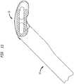
- spacer 10in accordance with one embodiment of the present invention.
- spacer 10includes a body 12, which in turn includes a front end 14, a rear end 16, an anterior side 18, a posterior side 20, a top surface 22, and a bottom surface 24.
- Spacer 10further includes an interface 26, including a neck portion 28, a lip portion 30, and a notch 32. Notch 32 separates interface 26 into first and second segments 26a and 26b (best shown in Figs. 2 and 3 ), respectively.
- interface 26is arcuate and can best be described as a rail.
- interface 26can vary in shape, size, and configuration, with the only limitation being its cooperation with an insertion tool, such as the one discussed more fully below.
- notch 32is shown as extending in a direction substantially parallel to a longitudinal axis of spacer 10, and neck portion 28 and lip portion 30 are shown as forming a T-shape. Again, these elements can vary in other embodiments.
- Spacer 10is preferably constructed of a polymeric material, such as polyetheretherketone ("Peek"). However, spacer 10 may be constructed of practically any materials suitable for implantation in the body of a human. Front end 14 and rear end 16 are shown as being curved, where the curves of the rear end and arcuate interface 26 lie in concentric circles. Again, in other embodiments, this configuration may vary. For instance, it is contemplated to provide a substantially square or rectangular shaped spacer 10. In the embodiment shown in Figs. 1-4 , front end 14 defines a tapered nose for spacer 10.
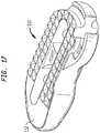
- front end 14may (additional to or in lieu of the tapered nose structure) include a steering element configured to mate with at least one of the adjacent vertebral bodies spacer 10 is designed to be placed between in order to cause rotation of spacer 10 during insertion.
- a steering elementmay include a fin or crease, and may be disposed at an angle with respect to longitudinal axis of spacer 10.
- spacer 110 of this typeis depicted in Fig. 17 , in which a steering element 112 takes the form of a crease.
- a steering element 112takes the form of a crease.
- other designsmay be employed.
- top and bottom surfaces 22 and 24each include a plurality of bone-engaging features in the form of teeth 34. Other features may be employed for aiding in the fixation of spacer 10 to the adjacent vertebrae.
- Spacer 10also includes apertures 36a and 36b formed through top and bottom surfaces 22 and 24. Apertures 36a and 36b are separated by a strut 38, which is recessed with respect to both top and bottom surfaces 22 and 24. In other embodiments, strut 38 may be formed flush with top and bottom surfaces 22 and 24, or only recessed with respect to one or the other. Apertures 36a and 36b are preferably designed to receive bone growth material, as will be discussed more fully below.
- Spacer 10further includes lateral fenestrations 40a and 40b, which are preferably designed for allowing fusion that develops between the upper and lower vertebrae (through the spacer) to spread laterally as well, and a plurality of vertical markers 42a and 42b, which are preferably constructed of tantalum and press fitted into spacer 10. Markers 42a and 42b make the visual identification of spacer 10 easier through a traditional X-ray technique.
- Spacer 10 shown in Figs. 1-4preferably includes a length dimension from front end 14 to rear end 16 that is preferably within the range of 15mm to 40mm, and more preferably between 26mm and 31mm, as well as a length dimension from front end 14 to the end of interface 26 that is preferably within the range of 17mm to 42mm, and more preferably between 28mm and 32mm.
- a width dimension from anterior side 18 to posterior side 20 of spacer 10 shown in Figs. 1-4is preferably in the range of 8mm to 16mm, and more preferably approximately 12mm.
- Spacer 10 shown in Figs. 1-4also preferably includes a height dimension from top surface 22 to bottom surface 24 within the range of 6mm to 15mm.
- spacer 10may be of any size. For instance, spacers 10 designed for use in the cervical area of the spine may be smaller than spacers 10 designed for use in the thoracic or lumber spine.
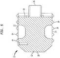
- FIG. 5depicts a version of spacer 10 exhibiting top and bottom surfaces 22 and 24 that taper from anterior side 18 to posterior side 20.
- This tapered constructionpreferably aids in restoring the natural lordotic angle of the adjacent vertebrae.
- the angle of each taperis preferably within the range of zero to ten degrees with respect to the midplane of spacer 10 to comport with the natural lordotic angle, but may be any angle suitable for use in the spine.
- the particular patient anatomywill generally determine whether a spacer like that shown in Figs. 1-4 or in Fig. 5 will be required. However, a surgeon may employ one design or the other for other reasons.
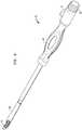
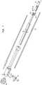
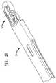
- Figs. 6-9depict an insertion tool 50 for use in inserting and positioning a prosthetic intervertebral spacer, for instance, above-described spacer 10, in the intervertebral disc space between two adjacent vertebra.
- insertion tool 50includes a grasping portion 52 having first and second arms 54a and 54b that are preferably capable of moving with respect to one another.
- arms 54a and 54bact as spring clips having proximal ends attached to other portions of grasping portion 52 and distal ends between which the dimension can be varied.
- arms 54a and 54bmay be movable in other fashions, such as rotatable or the like.
- Tool 50further includes a sleeve 56 having an inner surface 57 that is slidably disposed about grasping portion 52.
- a portion of inner surface 57 of sleeve 56includes opposing surfaces that are preferably spaced apart by a dimension that is less than a resting dimension between the outer portions of arms 54a and 54b. This allows for the distance between arms 54a and 54b to be reduced upon sliding of the sleeve distally. This preferably allows for arms 54a and 54b to be in an initial position, such as separated by the resting dimension, where they are able to receive spacer 10, and where sliding of sleeve 56 causes arms 54a and 54b to affix to interface 26.
- arms 54a and 54beach preferably include projections 58a and 58b, respectively, for positioning adjacent to the shoulder formed between neck portion 28 and lip portion 30 of interface 26.
- arms 54a and 54b and projections 58a and 58bare preferably curved to properly mate with the curvature of interface 26 and therefore to allow rotation of spacer 10 with respect to tool 50. The rotational relationship between spacer 10 and tool 50 will be discussed more fully below.
- tool 50further includes a handle portion 60 connected to grasping portion 52.
- Handle portion 60preferably further includes a sleeve actuator 62 for causing sliding movement of sleeve 56.
- sleeve actuator 62includes a rotatable knob, the rotation of which causes the sliding of sleeve 56.
- Handle portion 60also preferably includes a rod actuator 63 for causing movement of a rod 64 (best shown in Figs. 7 and 8 ) that acts as a rotational lock for spacer 10.
- rod actuator 63takes the form of a switch, the sliding of which causes movement of rod 64.
- Handle portion 60also preferably includes a grip 66 that may be ergonomically shaped and formed with a material suitable for grasping by a surgeon.
- Figs. 9-13depict the mating relationship between spacer 10 and insertion tool 50.
- the initial connection between spacer 10 and tool 50is depicted.
- arms 54a and 54bare preferably in an initial state suitable for receiving interface 26 of spacer 10.
- the inserteris shown with sleeve 56 slid over arms 54a and 54b to affix spacer 10 to tool 50.
- rod 64is shown deployed into notch 32.
- spacer 10can neither be removed from nor rotated with respect to tool 50.
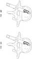
- Fig. 11depicts spacer 10 rotated with respect to tool 50. Essentially, in Fig. 11 , rod 64 has been disengaged from notch 32 through actuation of rod actuator 64.
- Fig. 12depicts spacer 10 rotated at a maximum amount with respect to tool 50. This amount is approximately 80 degrees, but may be greater in other embodiments, including approximately 90 degrees.
- Figs. 9 and 10depicted the majority of tool 50 being connected with first segment 26a of interface 26
- Fig. 12depicts the majority of tool 50 being connected with second segments 26b due to the rotation of spacer 10 with respect to tool 50.
- Fig. 13depicts spacer 10 having been released from tool 50 upon sliding of sleeve 56 in the opposite direction from which it is shown in Figs. 10-12 .
- Figs. 14 and 15depict the spacer 10 and tool 50 construct discussed above in relation to two adjacent vertebral bodies in the spine of a human being.
- Fig. 14depicts spacer 10 being inserted from a posterior aspect of the spine
- spacer 10may be inserted from any aspect.
- spacer 10is inserted from an anterior aspect of the spine.
- Fig. 15in a final position located in an anterior portion of the intervertebral disc space, spacer 10 may ultimately be disposed in many different areas of that intervertebral disc space.
- spacer 10may ultimately be implanted so as to be located in a posterior portion of the intervertebral space.
- Figs. 16a-16gdepict in more detail one embodiment method of inserting and positioning spacer 10 in the intervertebral disc space between two adjacent vertebra with the use of tool 50.
- a surgeonPrior to conducting the method shown in those figures, a surgeon preferably forms a hole through the annulus fibrosis of an intervertebral disc space, leaving a large amount of that anatomical feature untouched. The surgeon may then remove (through the formed hole or otherwise) certain material from the space in order to allow for spacer 10 to be inserted therein. Thereafter, as shown in Fig. 16a , the locked spacer 10 and tool 50 construct shown in Fig. 10 is inserted through the hole formed through the annulus fibrosis. Again, while this is shown in Fig.
- FIG. 16adepicts spacer 10 as having occurred from a posterior lateral aspect, other entry aspects may be utilized in inserting spacer 10.
- rod actuator 63is actuated to withdraw the rotational lock provided by rod 64 being disposed within notch 32.
- Spacer 10is then allowed to rotate with respect to tool 50 during further insertion of the construct within the space, as front end 14 engages the remaining portion of the annulus fibrosis.
- Figs. 16c-16edepict subsequent and sequential steps in this insertion process.
- Fig. 16fdepicts spacer 10 fully rotated with respect to insertion tool 50 and disposed in an anterior portion of the disc space where, in this embodiment, it shall remain.
- Fig. 16gdepicts tool 50 being removed from spacer 10. This is due to operation of sleeve actuator 62 to slide sleeve 56 with respect to grasping portion 52. Spacer 10 is now in its final position and tool 50 can be removed from the space.
- the methods of inserting spacer 10may further include the steps of packing apertures 36a and 36b with bone growth inducing substances, such as bone morphogenetic proteins or natural bone materials.
- spacer 10includes a steering element
- the rotation between spacer 10 and tool 50may occur prior to engagement of spacer 10 with the remaining portion of the annulus fibrosis.
- the tapered nose of front end 14 of spacer 10preferably aids in the initial insertion of the spacer within the intervertebral disc space, as well as the cooperation of the spacer with the remaining portion of the annulus fibrosis.
- the present inventionenjoys wide industrial applicability including, but not limited to, systems and methods for providing and implanting a prosthetic intervertebral spacer.
Landscapes
- Health & Medical Sciences (AREA)
- Engineering & Computer Science (AREA)
- Biomedical Technology (AREA)
- Orthopedic Medicine & Surgery (AREA)
- Neurology (AREA)
- Transplantation (AREA)
- Heart & Thoracic Surgery (AREA)
- Oral & Maxillofacial Surgery (AREA)
- Cardiology (AREA)
- Vascular Medicine (AREA)
- Life Sciences & Earth Sciences (AREA)
- Animal Behavior & Ethology (AREA)
- General Health & Medical Sciences (AREA)
- Public Health (AREA)
- Veterinary Medicine (AREA)
- Physical Education & Sports Medicine (AREA)
- Prostheses (AREA)
Description
- The present application claims the benefit of Application Serial No.
12/894,796, filed September 30, 2010 - The present invention relates to spinal implants and methods of implanting such implants. More particularly, the present invention relates to a spinal implant having a guiding rail for cooperating with an insertion instrument, as well as the methods associated with implanting that implant.
- Back pain can be caused by many different things, including any one of several problems that affect the intervertebral discs of the spine. These disc problems include, for instance, degeneration, bulging, herniation, thinning of a disc, and abnormal movement, and the pain that is experienced is generally attributable to friction or pressure that inevitably occurs when one adjacent vertebra exerts uneven pressure or when both adjacent vertebrae exert such pressure on the disc. Oftentimes, disc problems lead to the vertebrae impinging on one of the very many nerves located in the spinal column.
- One surgical method commonly utilized to correct such disc problems is a fusion procedure where a surgeon fuses together adjacent vertebrae in single or multiple levels. Different methods (as well as apparatus for use in those methods) for such surgery have been developed for performance on cervical, thoracic, or lumbar vertebral bodies. These fusion procedures will be referred to herein as interbody fusion or "IF." Traditional IF techniques generally involve removing at least a portion of the troublesome disc from the patient, inserting a spinal implant device into the space to hold the graft material in place and to support the vertebrae while solid bone mass forms therebetween, and adding bone graft material into the interbody space between the vertebrae that flank the disc. Oftentimes, the steps of inserting an implant and bone graft material involve first packing the implant with the bone graft material, and thereafter implanting that construct.
- While IF is a long-established technique for correcting the aforementioned disc problems, it is one that is constantly updated. For instance, different implants have been created to suit specific needs, and methods involving the insertion of such implants and the preparation of the vertebrae to receive same are constantly evolving. One major issue that has existed and will continue to exist is the fact that visibility to the surgical site is often hindered by the patient anatomy. For instance, in the cervical section of the spine, the vertebral bodies are rather small and surrounding patient anatomy, such as the esophagus and other body parts, makes access to and visibility of the surgical site rather difficult. This often hinders the surgeon in properly positioning an implant with respect to the vertebrae. Furthermore, in many IF procedures, the required manipulation of the patient anatomy, distraction of the vertebral bodies, and preparation of the vertebral bodies often results in significant scar tissue being formed in the patient. This can be detrimental when performing any subsequently required spinal procedures.
- Documents
US 2007/282441 ,US 2006/235426 andWO 2010/011849 disclose some example of spinal implants and the corresponding methods of implanting such implants. There exists however a need for a spinal implant and method of using the implant that improves upon the above described shortcomings. - A first aspect of the present disclosure is a prosthetic intervertebral spacer of the invention as defined in appended
claim 1 and corresponding dependent claims. - In accordance with other embodiments of the first aspect, the lip portion may be wider than the neck portion in the direction extending between the top and bottom surfaces. Additionally, a notch may be included in the interface, thereby separating the rail into a first rail segment and a second rail segment. The first rail segment may be disposed on the rear end of the spacer, and the second rail segment may be disposed on the posterior side of the spacer. The notch may extend in a direction substantially parallel to a longitudinal axis of the spacer.
- In accordance with still other embodiments of the first aspect, the rear end of the spacer may be curved, so that in certain cases, the curves of the rear end and the arcuate interface may lie on concentric circles. In other embodiments, the front end may be curved, and may include a steering element configured to mate with an adjacent vertebral body to cause rotation of the spacer during insertion. In certain embodiments, the steering element may be a fin or a crease, and may be disposed at an angle with respect to a longitudinal axis of the spacer. Still further, the spacer may include at least one aperture extending between the upper and lower surfaces. The aperture may allow for bone growth inducing substances to be placed therein.
- A second, non-claimed aspect of the present disclosure relates to another prosthetic intervertebral spacer. In accordance with one embodiment of the second aspect, the spacer includes a body defined by an outer wall having a convexly curved front end, a convexly curved rear end, a convex anterior side, a concave posterior side, a top surface, and a bottom surface. The spacer further includes an arcuate interface protruding from the outer wall and being connected to the rear end and the posterior side of the body, where the interface is a rail including a neck portion connected to the body and a lip portion connected to the neck portion. The lip portion has a fist dimension greater than a second dimension of the neck portion, and the outer wall has a third dimension greater than the first dimension, the first and third dimensions extending between the top and bottom surfaces.
- In accordance with other embodiments of this second aspect, the rail may further include a notch separating the rail into first and second rail segments. The notch may extend in a direction substantially parallel to the longitudinal axis of the spacer. The first rail segment may be disposed on the rear end of the spacer, and the second rail segment may be disposed on the posterior side of the spacer. Further, the neck portion and lip portion of the interface may form a T shape.
- In other embodiments according to the second aspect, the front end may include a steering element configured to mate with an adjacent vertebral body to cause rotation of the spacer. The steering element may be a fin or a crease. Additionally, the steering element may be disposed at an angle with respect to the longitudinal axis of the spacer. Finally, the spacer may include at least one aperture extending between the upper and lower surfaces. The aperture may allow for bone growth inducing substances to be placed therein.
- A third, non-claimed aspect of the present disclosure relates to another prosthetic intervertebral spacer. This spacer according to the third aspect may include a body having a front end, a rear end, an anterior side, a posterior side, and a longitudinal axis. The front end preferably mates with the anterior side at a transition portion that is curved, the transition portion being configured to interact with an annulus fibrosis of an intervertebral disc to cause rotation in the spacer during insertion of the spacer. The spacer may further include an arcuate interface extending away from the body and being connected to the rear end and the posterior side of the body. In certain embodiments, the interface may be a rail including a neck portion connected to the body and a lip portion connected to the neck portion, the lip portion being wider than the neck portion in the direction extending between the top and bottom surfaces.
- A fourth, non-claimed aspect of the present disclosure relates to a surgical tool for inserting and positioning a prosthetic intervertebral spacer in the intervertebral disc space between two adjacent vertebrae. In accordance with one embodiment of the fourth aspect, the tool includes a grasping portion including first and second arms having proximal and distal ends, the distal ends being separated by a first dimensions; a sleeve having an inner surface, the sleeve being slidably disposed about the grasping portion, at least the portion of the inner surface having an inner dimension less than the first dimension; a handle portion connected to the proximal ends in the first and second arms, the handle portion having a rod actuator and a sleeve actuator, the sleeve actuator connected to the sleeve to slide the sleeve with respect to the first and second arms; and a rod having a first end disposed adjacent the distal ends of the first and second arms and a second end, the rod actuator connected to the second end to slide the rod with respect with to the grasping portion.
- In accordance with other embodiments of the fourth aspect of the present invention, the first and second arms may be flexibly connected to the handle portion such that the distal ends of the first and second arms can move toward and away from another. Further, the first and second arms may also include proximal ends separate by a second distance less than the first distance. Each of the distal ends of the first and second arms may include a projection facing toward the opposite arm for engagement to an interface of the spacer. The distal ends of the first and second arms may be curved to mate with the inner face of the spacer.
- In still further embodiments, the inner dimension may be greater than the second distance. The handle portion may include a grip and a shaft portion, the shaft portion having a proximal end connected to the grip and a distal end connected to the grasping portion. Likewise, the sleeve actuator may include a rotatable knob disposed on the handle portion. Still further, the rod actuator may include a slidable switch disposed on the handle portion and a screw for locking the slidable switch with respect to the handle portion.
- A fifth, non-claimed aspect of the present disclosure relates to a method of using a surgical tool for inserting and positioning a prosthetic intervertebral spacer in the intervertebral disc space between two adjacent vertebrae. In accordance with one embodiment of this aspect, the method may include the steps of providing a surgical tool including a grasping portion having first and second arms having proximal and distal ends, the distal ends being separated by a first dimension; a sleeve having an inner surface, the sleeve being slidably disposed about the grasping portion, at least a portion of the inner surface having an inner dimension less than the first dimension; a handle portion connected to the proximal ends of the first and second arms, the handle portion having a rod actuator and a sleeve actuator, the sleeve actuator connected to the sleeve to slide the sleeve with respect to the first and second arms; and a rod having a first end disposed adjacent the distal ends of the first and second arms and a second end, the rod actuator connected to the second end to slide the rod with respect to the grasping portion. The method may also include the steps of positioning distal ends of the first and second arms adjacent in interface of an intervertebral spacer, moving the sleeve such that the portion of the inner surface to the sleeve having the inner dimension overlaps the distal ends of the first and second arms, thereby engaging the tool to the interface of the spacer, and engaging the first end of the rod to a notch in the spacer.
- In accordance with other embodiments of the fifth aspect, the method may further include the steps of inserting the spacer into the intervertebral disc space, disengaging the first end of the rod from the notch, and/or further inserting the spacer into the intervertebral space when the rod is disengaged from the notch. The tool may be configured to slide along the interface of the spacer when engaged with the spacer, where the step of further inserting the spacer includes sliding the tool along the interface of the spacer while the spacer rotates in the intervertebral disc space. Relative rotation of the spacer may be prevented when the rod is engaged to the notch and permitted when the rod is disengaged from the notch. The step of disengaging may be conducted when the spacer contacts a portion of an annulus fibrosis in the anterior portion of the intervertebral disc space.
- In further embodiments, the method of the fifth aspect may further include the step of forming a hole through only a portion of the annulus fibrosis while leaving the remainder of the annulus fibrosis in tact, where the step of inserting includes inserting the spacer through the hole. The step of moving the sleeve may include actuating the sleeve actuator. The method may further include the step of tightening the grip of the tool on the spacer by rotating a rotatable knob of the sleeve actuator. The step of engaging the first end of the rod may include actuating a rod actuator. The step of actuating may include sliding a slidable switch through the road actuator with respect to the handle portion and locking the slidable switch to the handle portion by tightening the screw of the rod actuator. The method may further include the step of disengaging the first end of the rod from the notch by loosening the screw and sliding the slidable switch with respect to the handle portion. The first and second arms of the tool may be flexibly connected to the handle portion and the step of moving the sleeve may cause the distal ends of the first and second arms to move toward one another. In still further embodiments, each of the distal ends of the first and second arms may include a projection facing toward the opposite arm for engagement to an interface of the spacer, and the step of moving the sleeve may cause the distal ends of the first and second arms to engage the projections to mating channels in the interface of the spacer. Additionally, the handle portion may include a grip and a shaft portion, the shaft portion having a proximal end connected to the grip and a distal end connected to the grasping portion.
- A sixth, non-claimed aspect of the present disclosure relates to another method of using a surgical tool for inserting and positioning a prosthetic intervertebral spacer in the intervertebral disc space between two adjacent vertebrae. The method according to the sixth aspect may include the steps of positioning distal ends of first and second arms with a surgical tool adjacent an interface of intervertebral spacer, the distal ends being separated by a first dimension, moving a sleeve of the tool such that a portion of an inner surface of the sleeve having an inner dimension less than the first dimension overlapped the distal ends of the first and second arms, thereby engaging the tool to the interface of the spacer, and engaging a rod of the tool to a notch in the spacer.
- In accordance with embodiments of the sixth aspect, the method may further include the steps of inserting the spacer into the intervertebral space, disengaging the rod from the notch, and/or further inserting the spacer into the intervertebral space when the rod is disengaged from the notch. In further embodiments, the tool may be configured to slide along the interface of the spacer when engaged with the spacer, with the step of further inserting the spacer includes sliding the tool along the interface of the spacer while the spacer rotates in the intervertebral disc space. Relative rotation between the spacer and the tool may be prevented when the rod is engaged to the notch and permitted when the rod is disengaged from the notch. The step of disengaging may be conducted when the spacer contacts the annulus fibrosis in the anterior portion of the intervertebral disc space.
- Further, the method of this sixth aspect, may further comprise the step of forming a hole through only a portion of the annulus fibrosis while leaving the remainder of the annulus fibrosis in tact, where the step of inserting includes inserting the spacer through the hole. The step of moving the sleeve may include actuating the sleeve actuator of the tool thereby tightening the grip of the tool on the spacer by rotating a rotatable knob of the sleeve aperture. The step of engaging the rod may include actuating the rod actuator of the tool, including sliding the slidable switch of the rod actuator with respect to the handle portion and locking the slidable switch to the handle portion by tightening a screw of the rod actuator. The method may further comprise the step of disengaging the first end of the rod from the notch by loosening the screw and sliding the slidable switch with respect to the handle portion. The first and second arms of the tool may be flexibly connected to a handle portion of the tool, and the step of moving a sleeve may cause the distal ends of the first and second knobs to move towards one another. Each of the distal ends of the first and second arms may include a projection facing toward the opposite arm for engagement to an interface of the spacer, and the step of moving the sleeve may cause the distal ends of the first and second arms to engage the projections to mating channels in the interface of the spacer.
- A seventh, non-claimed aspect of the present disclosure relates to a method of inserting and positioning a prosthetic intervertebral spacer in an intervertebral disc space between two adjacent vertebrae. In accordance with one embodiment of the seventh aspect, the method may include the steps of providing a spacer including a body having a front end, a rear end, a longitudinal axis, and an interface extending away from the body and being connected to the rear end of the body, engaging a tool to the interface; inserting the spacer at least partially into the intervertebral disc space by moving the tool along an insertion direction; and allowing the spacer to rotate with respect to the insertion direction within in the intervertebral disc space while continuing to move the tool along the insertion direction.
- In accordance with certain embodiments of the seventh aspect, the tool may maintain its engagement to the interface during the steps of inserting and allowing. The step of allowing the spacer to rotate may include allowing the front end to interact with an annulus fibrosis of an intervertebral disc to cause rotation in the spacer with respect to the insertion direction. The method may further include the step of forming a hole through only a portion of the annulus fibrosis while leaving the remainder of the annulus fibrosis in tact, where the step of inserting includes inserting the spacer through the hole. The spacer may be inserted such that the spacer is positioned in an anterior aspect of the intervertebral disc space. The spacer may be inserted to a final position where the longitudinal axis of the spacer is perpendicular to the insertion direction. The longitudinal axis of the spacer may be substantially parallel to a medial lateral axis of the intervertebral disc space. The spacer may be inserted such that the longitudinal axis of the spacer is rotated approximately 80 degrees with respect to the insertion direction. The allowing step may include allowing the tool to slide along the interface during rotation of the spacer. The insertion direction may be substantially parallel to a posterior-anterior axis of the intervertebral disc space. The interface of the spacer may include a notch and the tool may include a rod engageable to the notch, where the method further includes the step of engaging the rod to the notch to prevent relative rotation between the spacer and the tool and the step of disengaging the rod from the notch to allow relative rotation between the spacer and the tool. The allowing step may take place after the rod is disengaged from the notch. The spacer may at least be partially inserted with the rod engaged to the notch and at least partially inserted with the rod from the notch. The body may further include a top surface, a bottom surface, and at least one aperture extending between the top and bottom surfaces, where the method further includes the step of packing bone graft material into the at least one aperture. The spacer may further include a front end having frictional properties that are greater than frictional properties of a rear end in the spacer to aid in the rotation of the spacer within the intervertebral space. The step of allowing the spacer to rotate further may include allowing a steering element disposed on the front end of the spacer to mate with one of the two adjacent vertebral bodies to cause rotation of the spacer with respect to the insertion direction. The steering element may be disposed at an angle with respect to the longitudinal axis. The steering element may be a fin or crease.
- An eighth, non-claimed aspect of the present disclosure relates to another method of inserting and positioning a prosthetic intervertebral spacer in an intervertebral disc space between two adjacent vertebrae. In accordance with one embodiment of the eighth aspect, the method may include the steps of providing a spacer including a body having a front end, a rear end, a longitudinal axis, and an interface extending away from the body and being connected to the rear end of the body, the interface including a notch; engaging a tool to be interface, the tool including a rod; engaging the rod to the notch to prevent relative rotation between the spacer and the tool; inserting the spacer at least partially into the intervertebral disc space by moving the tool along an insertion direction; disengaging the rod from the notch; inserting the spacer further into the intervertebral disc space after the disengaging step by moving the tool substantially along the insertion direction; and allowing the spacer to rotate with respect to the insertion direction within the intervertebral disc space when the rod is disengaged from the notch while continuing to move the tool along the insertion direction.
- In accordance with certain embodiments of the eighth aspect, the method may further include the step of forming a hole through only a portion of an annulus fibrosis while leaving the remainder of the annulus fibrosis intact, where the step of inserting includes inserting the spacer through the hole. The step of allowing the spacer to rotate may include allowing the front end to interact with an annulus fibrosis of an intervertebral disc to cause rotation to the spacer with respect to the insertion direction. The tool may maintain its engagement to the interface during the steps of inserting and allowing. The spacer may be inserted such that the spacer's position in an anterior aspect of the intervertebral disc space. The spacer may be inserted to a final position where the longitudinal axis of the spacer is perpendicular to the insertion direction. The longitudinal axis of the spacer may be substantially parallel to a medial-lateral axis of the intervertebral disc space. The spacer may be inserted such that the longitudinal axis of the spacer is rotated approximately 80 degrees with respect to the insertion direction. The allowing step may include allowing the tool to slide along the interface during rotation of the spacer. The front end of the spacer may include a steering element, and the step of allowing the spacer to rotate further may include allowing the steering element to mate with one of the adjacent vertebral bodies to cause a rotation of the spacer with respect to the insertion direction. The steering element may be disposed at an angle with respect to the longitudinal axis. The steering element may be a fin or crease. The insertion direction may be substantially parallel to a posterior that is entered axially in a vertebral disc space.
- Further, the body may include a top surface, a bottom surface, and at least one aperture extending between the top and bottom surfaces, where the method further includes the step of packing bone graft material into the at least one aperture. The spacer may further include a front end having frictional properties that are greater than frictional properties of a rear end of the spacer to aid in the rotation of the spacer within the intervertebral disc space. The first step of inserting may include applying a force to the spacer along a first axis substantially parallel to the longitudinal axis of the spacer, and the second step of inserting may include applying a force to the spacer along a second axis forming an angle with the axis of great than zero degrees.
- A ninth, non-claimed aspect of the present disclosure relates to another method of inserting and positioning a prosthetic intervertebral spacer in an intervertebral disc space between two adjacent vertebrae. In accordance with one embodiment of the ninth aspect, the method may include the steps of providing a spacer including a body having a front end, a rear end, a longitudinal axis, and an interface extending away from the body and being connected to the rear end of the body; applying a force to a tool engaged to the interface to move the spacer in the intervertebral disc space, the force being directed along an insertion direction; and allowing the front end to interact with an annulus fibrosis of an intervertebral disc to cause rotation in the spacer with respect to the insertion direction while continuing to move the tool along the insertion direction.
- In other embodiments of the ninth aspect, the method may further include the step of forming a hole through only a portion of the annulus fibrosis while leaving the remainder of the annulus fibrosis intact, and the step of inserting the spacer through the hole. The engaging between the tool and the interface may be maintained during the steps of applying and allowing. The allowing step may include allowing the tool to slide along the interface during rotation of the spacer. The interface of the spacer may include a notch and the tool may include a rod engaged to the notch, where the method further includes the step of engaging the rod to the notch to prevent relative rotation between the spacer and the tool and the step of disengaging the rod from the notch to allow relative rotation between the spacer and the tool. The allowing step may take place after the rod is disengaged from the notch. The spacer may be at least partially inserted with the rod engaged to the notch and at least partially inserted with the rod disengaged from the notch. The step of allowing may include allowing a steering element disposed on the front end of the spacer to meet with an adjacent vertebral body to cause rotation of the spacer with respect to the insertion direction. The steering element may be disposed at an angle with respect to the longitudinal axis. The steering element may be a fin or a crease. The step of applying may include the insertion direction being substantially parallel to the longitudinal axis of the spacer and the method may further include the step of applying a second force to the spacer along the second axis forming an angle with the longitudinal axis of greater than zero degrees.
- A more complete appreciation of the subject matter of the present invention and the various advantages thereof can be realized by reference to the following detailed description in which reference is made to the accompanying drawings in which:
Fig. 1 is a front perspective view of a prosthetic intervertebral spacer in accordance with one embodiment of the present invention.Fig. 2 is a top perspective view of the spacer shown inFig. 1 .Fig. 3 is a top view of the spacer shown inFig. 1 , the bottom view being a mirror image thereof.Fig. 4 is a side view of the spacer shown inFig. 1 .Fig. 5 is a cross-sectional view of a modified version of the spacer shown inFig. 1 , the section being taken through the modified version in a similar fashion to line X-X ofFig. 1 .Fig. 6 is a perspective view of a surgical tool for use in inserting and positioning a prosthetic intervertebral spacer in accordance with one embodiment of the present invention.Fig. 7 is an exploded view of the insertion tool shown inFig. 6 .Fig. 8 is an enlarged exploded view of a portion of the view ofFig. 7 .Fig. 9 is in illustration depicting an initial connection between the spacer shown inFig. 1 and the insertion tool shown inFig. 6 .Fig. 10 is an illustration depicting the spacer and insertion tool construct shown inFig. 9 with the insertion tool in a locked position.Fig. 11 is an illustration depicting the spacer and insertion tool construct shown inFig. 9 with the spacer rotated with respect to the insertion tool.Fig. 12 is an illustration of the spacer and insertion tool construct shown inFig. 9 with the spacer fully rotated with respect to the insertion tool.Fig. 13 is an illustration depicting the spacer and insertion tool construct shown inFig. 9 with the spacer released from the insertion tool.Fig. 14 is an illustration depicting the spacer and insertion tool construct shown inFig. 9 in relation to an intervertebral space.Fig. 15 is an illustration depicting the spacer and insertion tool construct shown inFig. 9 in relation to the intervertebral space, with the spacer in a fully inserted position.Figs. 16a-16g are illustrations depicting various stages of insertion of the spacer shown inFig. 1 in relation to the insertion tool shown inFig. 6 and a vertebral body.Fig. 17 is a perspective view of a prosthetic intervertebral spacer in accordance with another embodiment of the present invention.- In describing the preferred embodiments of the subject illustrated and to be described with respect to the drawings, specific terminology will be used for the sake of clarity. However, the invention is not intended to be limited to any specific terms used herein, and it is to be understood that each specific term includes all technical equivalents that operate in a similar manner to accomplish similar purpose.
- As used herein, when referring to bones or other parts of the body, the term "proximal" means closer to the heart and the term "distal" means more distant from the heart. The term "inferior" means toward the feet and the term "superior" means towards the head. The term "anterior" means towards the front part of the body or the face and the term "posterior" means towards the back of the body. The term "medial" means toward the midline of the body and the term "lateral" means away from the midline of the body.
- Referring to
Figs. 1-4 , there is shown a prostheticintervertebral spacer 10 in accordance with one embodiment of the present invention. As shown,spacer 10 includes abody 12, which in turn includes afront end 14, arear end 16, ananterior side 18, aposterior side 20, atop surface 22, and abottom surface 24.Spacer 10 further includes aninterface 26, including aneck portion 28, alip portion 30, and anotch 32.Notch 32 separates interface 26 into first andsecond segments Figs. 2 and3 ), respectively. In the embodiment shown inFigs. 1-4 ,interface 26 is arcuate and can best be described as a rail. However, in other embodiments,interface 26 can vary in shape, size, and configuration, with the only limitation being its cooperation with an insertion tool, such as the one discussed more fully below. Likewise, in the embodiments shown inFigs. 1-4 , notch 32 is shown as extending in a direction substantially parallel to a longitudinal axis ofspacer 10, andneck portion 28 andlip portion 30 are shown as forming a T-shape. Again, these elements can vary in other embodiments. Spacer 10 is preferably constructed of a polymeric material, such as polyetheretherketone ("Peek"). However,spacer 10 may be constructed of practically any materials suitable for implantation in the body of a human.Front end 14 andrear end 16 are shown as being curved, where the curves of the rear end andarcuate interface 26 lie in concentric circles. Again, in other embodiments, this configuration may vary. For instance, it is contemplated to provide a substantially square or rectangular shapedspacer 10. In the embodiment shown inFigs. 1-4 ,front end 14 defines a tapered nose forspacer 10. However, in other embodiments,front end 14 may (additional to or in lieu of the tapered nose structure) include a steering element configured to mate with at least one of the adjacent vertebral bodies spacer 10 is designed to be placed between in order to cause rotation ofspacer 10 during insertion. Such a steering element may include a fin or crease, and may be disposed at an angle with respect to longitudinal axis ofspacer 10. Oneexample spacer 110 of this type is depicted inFig. 17 , in which asteering element 112 takes the form of a crease. Of course, in other embodiments employing such a steering element, other designs may be employed.- In the embodiment shown, top and
bottom surfaces teeth 34. Other features may be employed for aiding in the fixation ofspacer 10 to the adjacent vertebrae.Spacer 10 also includesapertures bottom surfaces Apertures strut 38, which is recessed with respect to both top andbottom surfaces bottom surfaces Apertures Apertures Spacer 10 further includeslateral fenestrations vertical markers spacer 10.Markers spacer 10 easier through a traditional X-ray technique. Spacer 10 shown inFigs. 1-4 preferably includes a length dimension fromfront end 14 torear end 16 that is preferably within the range of 15mm to 40mm, and more preferably between 26mm and 31mm, as well as a length dimension fromfront end 14 to the end ofinterface 26 that is preferably within the range of 17mm to 42mm, and more preferably between 28mm and 32mm. A width dimension fromanterior side 18 toposterior side 20 ofspacer 10 shown inFigs. 1-4 is preferably in the range of 8mm to 16mm, and more preferably approximately 12mm.Spacer 10 shown inFigs. 1-4 also preferably includes a height dimension fromtop surface 22 tobottom surface 24 within the range of 6mm to 15mm. Of course, in other embodiments,spacer 10 may be of any size. For instance,spacers 10 designed for use in the cervical area of the spine may be smaller thanspacers 10 designed for use in the thoracic or lumber spine.- Although shown in
Figs. 1-4 as having top andbottom surfaces Fig. 5 depicts a version ofspacer 10 exhibiting top andbottom surfaces anterior side 18 toposterior side 20. This tapered construction preferably aids in restoring the natural lordotic angle of the adjacent vertebrae. The angle of each taper is preferably within the range of zero to ten degrees with respect to the midplane ofspacer 10 to comport with the natural lordotic angle, but may be any angle suitable for use in the spine. The particular patient anatomy will generally determine whether a spacer like that shown inFigs. 1-4 or inFig. 5 will be required. However, a surgeon may employ one design or the other for other reasons. Figs. 6-9 depict aninsertion tool 50 for use in inserting and positioning a prosthetic intervertebral spacer, for instance, above-describedspacer 10, in the intervertebral disc space between two adjacent vertebra. As is more clearly shown in the exploded view ofFigs. 7 and8 ,insertion tool 50 includes a graspingportion 52 having first andsecond arms arms portion 52 and distal ends between which the dimension can be varied. In other embodiments,arms Tool 50 further includes asleeve 56 having aninner surface 57 that is slidably disposed about graspingportion 52. A portion ofinner surface 57 ofsleeve 56 includes opposing surfaces that are preferably spaced apart by a dimension that is less than a resting dimension between the outer portions ofarms arms arms spacer 10, and where sliding ofsleeve 56causes arms arms projections neck portion 28 andlip portion 30 ofinterface 26. Moreover,arms projections interface 26 and therefore to allow rotation ofspacer 10 with respect totool 50. The rotational relationship betweenspacer 10 andtool 50 will be discussed more fully below.- As best shown in
Fig. 6 ,tool 50 further includes ahandle portion 60 connected to graspingportion 52.Handle portion 60 preferably further includes asleeve actuator 62 for causing sliding movement ofsleeve 56. In the embodiment shown,sleeve actuator 62 includes a rotatable knob, the rotation of which causes the sliding ofsleeve 56.Handle portion 60 also preferably includes arod actuator 63 for causing movement of a rod 64 (best shown inFigs. 7 and8 ) that acts as a rotational lock forspacer 10. In the embodiment shown,rod actuator 63 takes the form of a switch, the sliding of which causes movement ofrod 64.Handle portion 60 also preferably includes a grip 66 that may be ergonomically shaped and formed with a material suitable for grasping by a surgeon. Figs. 9-13 depict the mating relationship betweenspacer 10 andinsertion tool 50. With reference toFig. 9 , the initial connection betweenspacer 10 andtool 50 is depicted. As noted above,arms interface 26 ofspacer 10. With reference toFig. 10 , the inserter is shown withsleeve 56 slid overarms spacer 10 totool 50. In addition,rod 64 is shown deployed intonotch 32. Thus,spacer 10 can neither be removed from nor rotated with respect totool 50.Fig. 11 depictsspacer 10 rotated with respect totool 50. Essentially, inFig. 11 ,rod 64 has been disengaged fromnotch 32 through actuation ofrod actuator 64. The arcuate nature ofinterface 26 andarms Fig. 12 depictsspacer 10 rotated at a maximum amount with respect totool 50. This amount is approximately 80 degrees, but may be greater in other embodiments, including approximately 90 degrees. WhereFigs. 9 and10 depicted the majority oftool 50 being connected withfirst segment 26a ofinterface 26,Fig. 12 depicts the majority oftool 50 being connected withsecond segments 26b due to the rotation ofspacer 10 with respect totool 50. Finally,Fig. 13 depictsspacer 10 having been released fromtool 50 upon sliding ofsleeve 56 in the opposite direction from which it is shown inFigs. 10-12 .Figs. 14 and15 depict thespacer 10 andtool 50 construct discussed above in relation to two adjacent vertebral bodies in the spine of a human being. AlthoughFig. 14 depictsspacer 10 being inserted from a posterior aspect of the spine,spacer 10 may be inserted from any aspect. For instance, in other embodiments,spacer 10 is inserted from an anterior aspect of the spine. Likewise, although shown inFig. 15 in a final position located in an anterior portion of the intervertebral disc space,spacer 10 may ultimately be disposed in many different areas of that intervertebral disc space. For example,spacer 10 may ultimately be implanted so as to be located in a posterior portion of the intervertebral space.Figs. 16a-16g depict in more detail one embodiment method of inserting andpositioning spacer 10 in the intervertebral disc space between two adjacent vertebra with the use oftool 50. Prior to conducting the method shown in those figures, a surgeon preferably forms a hole through the annulus fibrosis of an intervertebral disc space, leaving a large amount of that anatomical feature untouched. The surgeon may then remove (through the formed hole or otherwise) certain material from the space in order to allow forspacer 10 to be inserted therein. Thereafter, as shown inFig. 16a , the lockedspacer 10 andtool 50 construct shown inFig. 10 is inserted through the hole formed through the annulus fibrosis. Again, while this is shown inFig. 16a as having occurred from a posterior lateral aspect, other entry aspects may be utilized in insertingspacer 10. Upon contact ofspacer 10 with a remaining portion of the annulus fibrosis(seeFig. 16b )rod actuator 63 is actuated to withdraw the rotational lock provided byrod 64 being disposed withinnotch 32.Spacer 10 is then allowed to rotate with respect totool 50 during further insertion of the construct within the space, asfront end 14 engages the remaining portion of the annulus fibrosis.Figs. 16c-16e depict subsequent and sequential steps in this insertion process.Fig. 16f depictsspacer 10 fully rotated with respect toinsertion tool 50 and disposed in an anterior portion of the disc space where, in this embodiment, it shall remain.Fig. 16g depictstool 50 being removed fromspacer 10. This is due to operation ofsleeve actuator 62 to slidesleeve 56 with respect to graspingportion 52.Spacer 10 is now in its final position andtool 50 can be removed from the space.- The methods of inserting
spacer 10 may further include the steps of packingapertures spacer 10 andtool 50 may occur prior to engagement ofspacer 10 with the remaining portion of the annulus fibrosis. In addition, it is to be understood that the tapered nose offront end 14 ofspacer 10 preferably aids in the initial insertion of the spacer within the intervertebral disc space, as well as the cooperation of the spacer with the remaining portion of the annulus fibrosis. - Although the invention herein has been described with reference to particular embodiments, it is to be understood that these embodiments are merely illustrative of the principles and applications of the present invention. It is therefore to be understood that numerous modifications may be made to the illustrative embodiments and that other arrangements may be devised.
- The present invention enjoys wide industrial applicability including, but not limited to, systems and methods for providing and implanting a prosthetic intervertebral spacer.
Claims (15)
- A prosthetic intervertebral spacer (10) comprising:a body (12) having a front end (14), a curved rear end (16), an anterior side (18), a posterior side (20), a top surface (22), and a bottom surface (24); andan arcuate interface (26) extending away from the body (12) and being connected to the rear end (16) and the posterior side (20) of the body (12),characterized in that the interface (26) is a rail including a neck portion (28) connected to the body (12) and a lip portion (30) connected to the neck portion (28), and the neck portion (28) and the lip portion (30) form a T-shape, wherein curves of the rear end (16) and the arcuate interface (26) lie on concentric circles.
- The spacer (10) of claim 1, wherein the lip portion (30) is wider than the neck portion (28) in a direction extending between the top (22) and bottom (24) surfaces.
- The spacer (10) of claim 1, further including a notch (32) separating the rail into a first rail segment (26a) and a second rail segment (26b).
- The spacer (10) of claim 3, wherein the notch (32) extends in a direction substantially parallel to a longitudinal axis of the spacer (10).
- The spacer (10) of claim 3, wherein the first rail segment (26a) is disposed on the rear end (16) of the spacer (10), and the second rail segment (26b) is disposed on the posterior side (20) of the spacer (10).
- The spacer (10) of claim 1, wherein the arcuate interface (26) is configured to engage with a surgical tool (50) for inserting and positioning the spacer (10) in the intervertebral disc space between two adjacent vertebrae, such that the tool (50) may slide along the interface (26) of the spacer (10) when engaged with the spacer (10) to allow rotation of the spacer (10) with respect to the tool (50).
- The spacer (10) of claim 1, wherein the front end (14) is curved.
- The spacer (10) of claim 1, wherein the front end (14) includes a steering element (112) configured to mate with an adjacent vertebral body to cause rotation of the spacer (10).
- The spacer (10) of claim 8, wherein the steering element (112) is a fin or a crease (112).
- The spacer (10) of claim 8, wherein the steering element (112) is disposed at an angle with respect to a longitudinal axis of the spacer (10).
- The spacer (10) of claim 1, wherein at least one aperture (36a) extends between the top (22) and bottom (24) surfaces.
- The spacer (10) of claim 11, wherein the lip portion (30) is wider than the neck portion (28) in a direction extending between the top (22) and bottom (24) surfaces.
- The spacer (10) of claim 1,
wherein the front end (14) is convexly curved, the rear end (16) is convexly curved, the anterior side (18) is convex, and the posterior side (20) is concave, the body (12) having an outer wall defined by the convexly curved front end (14), the convexly curved rear end (16), the convex anterior side (18), the concave posterior side (20), the top surface (22), and the bottom surface (24); and
wherein the arcuate interface (26) protrudes from the outer wall, wherein the lip portion (30) has a first dimension greater than a second dimension of the neck portion (28), and the outer wall has a third dimension greater than the first dimension, the first second and third dimensions extending between the top (22) and bottom (24) surfaces. - The spacer (10) of claim 1,
wherein the body (12) defines a longitudinal axis, the front end (14) mating with the anterior side (18) at a transition portion that is curved, the transition portion configured to interact with an annulus fibrosus of an intervertebral disc to cause rotation of the spacer (10) during insertion of the spacer (10); and
wherein the lip portion (30) is wider than the neck portion (28) in a direction extending between the top (22) and bottom (24) surfaces. - A kit comprising:the spacer (10) of claim 1, anda surgical tool (50) for inserting and positioning the spacer (10) in the intervertebral disc space between two adjacent vertebrae, the tool (50) including:a grasping portion (52) including first (54a) and second (54b) arms having proximal and distal ends, the distal ends being separated by a first dimension;a sleeve (56) having an inner surface (57), the sleeve (56) being slidably disposed about the grasping portion (52), at least a portion of the inner surface (57) having an inner dimension less than the first dimension;a handle portion (60) connected to the proximal ends of the first (54a) and second (54b) arms, the handle portion (60) having a rod actuator (63) and a sleeve actuator (62), the sleeve actuator (62) connected to the sleeve (56) to slide the sleeve (56) with respect to the first (54a) and second (54b) arms; anda rod (64) having a first end disposed adjacent the distal ends of the first (54a) and second (54b) arms and a second end, the rod actuator (63) connected to the second end to slide the rod (64) with respect to the grasping portion (52).
Applications Claiming Priority (2)
| Application Number | Priority Date | Filing Date | Title |
|---|---|---|---|
| US12/894,796US8858637B2 (en) | 2010-09-30 | 2010-09-30 | Surgical implant with guiding rail |
| EP11829818.1AEP2621412B1 (en) | 2010-09-30 | 2011-09-28 | Surgical implant with guiding rail |
Related Parent Applications (2)
| Application Number | Title | Priority Date | Filing Date |
|---|---|---|---|
| EP11829818.1ADivisionEP2621412B1 (en) | 2010-09-30 | 2011-09-28 | Surgical implant with guiding rail |
| EP11829818.1ADivision-IntoEP2621412B1 (en) | 2010-09-30 | 2011-09-28 | Surgical implant with guiding rail |
Publications (2)
| Publication Number | Publication Date |
|---|---|
| EP3023079A1 EP3023079A1 (en) | 2016-05-25 |
| EP3023079B1true EP3023079B1 (en) | 2017-10-25 |
Family
ID=45890468
Family Applications (2)
| Application Number | Title | Priority Date | Filing Date |
|---|---|---|---|
| EP11829818.1AActiveEP2621412B1 (en) | 2010-09-30 | 2011-09-28 | Surgical implant with guiding rail |
| EP15187400.5AActiveEP3023079B1 (en) | 2010-09-30 | 2011-09-28 | Surgical implant with guiding rail |
Family Applications Before (1)
| Application Number | Title | Priority Date | Filing Date |
|---|---|---|---|
| EP11829818.1AActiveEP2621412B1 (en) | 2010-09-30 | 2011-09-28 | Surgical implant with guiding rail |
Country Status (6)
| Country | Link |
|---|---|
| US (6) | US8858637B2 (en) |
| EP (2) | EP2621412B1 (en) |
| JP (2) | JP5891231B2 (en) |
| AU (1) | AU2011308888B2 (en) |
| CA (2) | CA2935245C (en) |
| WO (1) | WO2012044666A2 (en) |
Families Citing this family (35)
| Publication number | Priority date | Publication date | Assignee | Title |
|---|---|---|---|---|
| US9220547B2 (en) | 2009-03-27 | 2015-12-29 | Spinal Elements, Inc. | Flanged interbody fusion device |
| US20120277866A1 (en)* | 2011-04-28 | 2012-11-01 | Prakasam Kalluri | Angled Bullet-Nose Banana Cage |
| US9220607B2 (en) | 2011-10-28 | 2015-12-29 | Warsaw Oorthopedic, Inc. | Pivotable interbody implant system |
| FR3006170B1 (en)* | 2013-05-31 | 2015-06-26 | Osd Orthopaedic & Spine Dev | INTERSOMATIC PROSTHESIS PRODUCING INDIVIDUALIZED LORDOSE SETTING |
| FR3010628B1 (en) | 2013-09-18 | 2015-10-16 | Medicrea International | METHOD FOR REALIZING THE IDEAL CURVATURE OF A ROD OF A VERTEBRAL OSTEOSYNTHESIS EQUIPMENT FOR STRENGTHENING THE VERTEBRAL COLUMN OF A PATIENT |
| FR3012030B1 (en) | 2013-10-18 | 2015-12-25 | Medicrea International | METHOD FOR REALIZING THE IDEAL CURVATURE OF A ROD OF A VERTEBRAL OSTEOSYNTHESIS EQUIPMENT FOR STRENGTHENING THE VERTEBRAL COLUMN OF A PATIENT |
| US10478313B1 (en) | 2014-01-10 | 2019-11-19 | Nuvasive, Inc. | Spinal fusion implant and related methods |
| US10792168B2 (en) | 2015-02-06 | 2020-10-06 | Alphatec Spine, Inc. | Implant insertion instrument |
| TWI547259B (en)* | 2015-04-28 | 2016-09-01 | 鐿鈦科技股份有限公司 | Spinal fusion surgery instrument for implanting and intervertebral cage thereof |
| US9895235B2 (en)* | 2015-12-18 | 2018-02-20 | Warsaw Orthopedic, Inc. | Spinal implant system and method |
| WO2018109556A1 (en) | 2016-12-12 | 2018-06-21 | Medicrea International | Systems and methods for patient-specific spinal implants |
| WO2018112324A2 (en) | 2016-12-16 | 2018-06-21 | Advance Research System, Llc | Interbody implant with concave profiled nose |
| USD879295S1 (en) | 2017-02-13 | 2020-03-24 | Advance Research System, Llc | Spinal fusion cage |
| EP3612122B1 (en) | 2017-04-21 | 2023-12-20 | Medicrea International | A system for developing one or more patient-specific spinal implants |
| USD847339S1 (en) | 2017-06-26 | 2019-04-30 | Advanced Research System, LLC | Spinal fusion cage |
| EP3663082A4 (en)* | 2017-08-01 | 2021-04-28 | Ishihara Sangyo Kaisha, Ltd. | Three-dimensional structure, method for manufacturing same, and coating device |
| WO2019051260A1 (en) | 2017-09-08 | 2019-03-14 | Pioneer Surgical Technology, Inc. | Intervertebral implants, instruments, and methods |
| USD907771S1 (en) | 2017-10-09 | 2021-01-12 | Pioneer Surgical Technology, Inc. | Intervertebral implant |
| US10918422B2 (en) | 2017-12-01 | 2021-02-16 | Medicrea International | Method and apparatus for inhibiting proximal junctional failure |
| US11311314B2 (en)* | 2018-07-31 | 2022-04-26 | GetSet Surgical SA | Spinal surgery systems and methods |
| US11065126B2 (en)* | 2018-08-09 | 2021-07-20 | Stryker European Operations Holdings Llc | Interbody implants and optimization features thereof |
| AU2019342137A1 (en) | 2018-09-20 | 2021-03-25 | Spinal Elements, Inc. | Spinal implant device |
| US11039931B2 (en)* | 2019-02-01 | 2021-06-22 | Globus Medical, Inc. | Intervertebral spinal implant |
| US11925417B2 (en) | 2019-04-02 | 2024-03-12 | Medicrea International | Systems, methods, and devices for developing patient-specific spinal implants, treatments, operations, and/or procedures |
| US11944385B2 (en) | 2019-04-02 | 2024-04-02 | Medicrea International | Systems and methods for medical image analysis |
| US11877801B2 (en) | 2019-04-02 | 2024-01-23 | Medicrea International | Systems, methods, and devices for developing patient-specific spinal implants, treatments, operations, and/or procedures |
| US11173043B1 (en) | 2019-05-17 | 2021-11-16 | Joseph T. Robbins | Spinal interbody implants |
| JP6700511B1 (en)* | 2019-08-30 | 2020-05-27 | リーガエース株式会社 | System for guiding interbody spacers between bodies |
| US11737888B1 (en) | 2019-09-19 | 2023-08-29 | Advance Research System, Llc | Spinal fusion implant system and method |
| US11769251B2 (en) | 2019-12-26 | 2023-09-26 | Medicrea International | Systems and methods for medical image analysis |
| US11277689B2 (en) | 2020-02-24 | 2022-03-15 | Logitech Europe S.A. | Apparatus and method for optimizing sound quality of a generated audible signal |
| US11911284B2 (en) | 2020-11-19 | 2024-02-27 | Spinal Elements, Inc. | Curved expandable interbody devices and deployment tools |
| WO2022133456A1 (en) | 2020-12-17 | 2022-06-23 | Spinal Elements, Inc. | Spinal implant device |
| US12318144B2 (en) | 2021-06-23 | 2025-06-03 | Medicrea International SA | Systems and methods for planning a patient-specific spinal correction |
| GB202112071D0 (en)* | 2021-08-23 | 2021-10-06 | Invibio Knees Ltd | Surgical implant |
Citations (1)
| Publication number | Priority date | Publication date | Assignee | Title |
|---|---|---|---|---|
| US20100057204A1 (en)* | 2008-02-22 | 2010-03-04 | Murali Kadaba | Hydraulically Actuated Expanding Spine Cage With Extendable Locking Anchor |
Family Cites Families (135)
| Publication number | Priority date | Publication date | Assignee | Title |
|---|---|---|---|---|
| US4714469A (en) | 1987-02-26 | 1987-12-22 | Pfizer Hospital Products Group, Inc. | Spinal implant |
| US5609635A (en) | 1988-06-28 | 1997-03-11 | Michelson; Gary K. | Lordotic interbody spinal fusion implants |
| US5782830A (en) | 1995-10-16 | 1998-07-21 | Sdgi Holdings, Inc. | Implant insertion device |
| US6423095B1 (en) | 1995-10-16 | 2002-07-23 | Sdgi Holdings, Inc. | Intervertebral spacers |
| US5649931A (en) | 1996-01-16 | 1997-07-22 | Zimmer, Inc. | Orthopaedic apparatus for driving and/or removing a bone screw |
| US6159215A (en) | 1997-12-19 | 2000-12-12 | Depuy Acromed, Inc. | Insertion instruments and method for delivering a vertebral body spacer |
| DE19903764B4 (en) | 1998-01-23 | 2005-03-31 | Aesculap Ag & Co. Kg | Intervertebral implant |
| AT405367B (en) | 1998-01-23 | 1999-07-26 | Fuss Franz K Dipl Biomech Dr | Implant |
| AU760821B2 (en) | 1998-10-02 | 2003-05-22 | Synthes Gmbh | Spinal disc space distractor |
| US6174311B1 (en) | 1998-10-28 | 2001-01-16 | Sdgi Holdings, Inc. | Interbody fusion grafts and instrumentation |
| FR2897259B1 (en) | 2006-02-15 | 2008-05-09 | Ldr Medical Soc Par Actions Si | INTERSOMATIC TRANSFORAMINAL CAGE WITH INTERBREBAL FUSION GRAFT AND CAGE IMPLANTATION INSTRUMENT |
| US7717961B2 (en) | 1999-08-18 | 2010-05-18 | Intrinsic Therapeutics, Inc. | Apparatus delivery in an intervertebral disc |
| US7615076B2 (en) | 1999-10-20 | 2009-11-10 | Anulex Technologies, Inc. | Method and apparatus for the treatment of the intervertebral disc annulus |
| WO2001028469A2 (en) | 1999-10-21 | 2001-04-26 | Sdgi Holdings, Inc. | Devices and techniques for a posterior lateral disc space approach |
| US6830570B1 (en) | 1999-10-21 | 2004-12-14 | Sdgi Holdings, Inc. | Devices and techniques for a posterior lateral disc space approach |
| US6764491B2 (en) | 1999-10-21 | 2004-07-20 | Sdgi Holdings, Inc. | Devices and techniques for a posterior lateral disc space approach |
| DE19952939A1 (en) | 1999-11-03 | 2001-05-10 | Tutogen Medical Gmbh | Bone material implant |
| ATE390100T1 (en) | 2000-02-22 | 2008-04-15 | Warsaw Orthopedic Inc | SPINAL IMPLANT AND INTRODUCTION DEVICE |
| KR20030007469A (en) | 2000-03-22 | 2003-01-23 | 스콜리오 지엠비에취 | Cage-type intervertebral implant |
| USD493225S1 (en) | 2000-06-12 | 2004-07-20 | Ortho Development Corporation | Implant |
| US6579318B2 (en) | 2000-06-12 | 2003-06-17 | Ortho Development Corporation | Intervertebral spacer |
| US7169182B2 (en) | 2001-07-16 | 2007-01-30 | Spinecore, Inc. | Implanting an artificial intervertebral disc |
| US6719794B2 (en) | 2001-05-03 | 2004-04-13 | Synthes (U.S.A.) | Intervertebral implant for transforaminal posterior lumbar interbody fusion procedure |
| JP2003107946A (en) | 2001-10-01 | 2003-04-11 | Takao Kawamura | Fixing heat plate, fixing semicircular heating member, and belt-type fixing device |
| US8388684B2 (en)* | 2002-05-23 | 2013-03-05 | Pioneer Signal Technology, Inc. | Artificial disc device |
| AU2003286531A1 (en) | 2002-10-21 | 2004-05-13 | 3Hbfm, Llc | Intervertebral disk prosthesis |
| US7500991B2 (en) | 2002-12-31 | 2009-03-10 | Depuy Acromed, Inc. | Banana cage |
| US7828849B2 (en) | 2003-02-03 | 2010-11-09 | Warsaw Orthopedic, Inc. | Expanding interbody implant and articulating inserter and method |
| US7645232B2 (en) | 2003-05-16 | 2010-01-12 | Zimmer Spine, Inc. | Access device for minimally invasive surgery |
| US7806932B2 (en) | 2003-08-01 | 2010-10-05 | Zimmer Spine, Inc. | Spinal implant |
| US20060229627A1 (en) | 2004-10-29 | 2006-10-12 | Hunt Margaret M | Variable angle spinal surgery instrument |
| US7753958B2 (en) | 2003-08-05 | 2010-07-13 | Gordon Charles R | Expandable intervertebral implant |
| US7235082B2 (en) | 2003-08-12 | 2007-06-26 | Depuy Spine, Inc. | Device for insertion of implants |
| FR2861582B1 (en) | 2003-10-29 | 2006-02-10 | Eurosurgical | INTERSOMATIC CAGE FOR LUMBAR FUSION FIRST TRANSFORAMINAL AND CAGE HOLDER DEVICE |
| US7591852B2 (en) | 2003-12-02 | 2009-09-22 | Alphatec Spine, Inc. | Vertebral body replacement cage assembly |
| US7137997B2 (en) | 2003-12-29 | 2006-11-21 | Globus Medical, Inc. | Spinal fusion implant |
| EP1713408B1 (en)* | 2004-02-09 | 2010-09-15 | DePuy Spine, Inc. | Systems for spinal surgery |
| JP2007526049A (en) | 2004-03-10 | 2007-09-13 | セピテク・ファウンデーション | Implants for stable surgery in the chest and lumbar spine |
| US7470273B2 (en) | 2004-06-25 | 2008-12-30 | Ebi, Llc | Tool for intervertebral implant manipulation |
| US7608080B2 (en) | 2004-07-02 | 2009-10-27 | Warsaw Orthopedic, Inc. | Device for inserting implants |
| US20060014285A1 (en)* | 2004-07-14 | 2006-01-19 | Eldridge Gary R | Methods and compositions for inhibiting biofilms |
| US7585326B2 (en) | 2004-08-06 | 2009-09-08 | Spinalmotion, Inc. | Methods and apparatus for intervertebral disc prosthesis insertion |
| JP2006068086A (en)* | 2004-08-31 | 2006-03-16 | Takiron Co Ltd | Artificial spinal disk insertion tool and tool set |
| EP1793807A2 (en) | 2004-09-28 | 2007-06-13 | The Hong Kong University of Science and Technology | Multifunctional supramolecular hydrogels as biomaterials |
| US8613747B2 (en) | 2004-10-20 | 2013-12-24 | Vertiflex, Inc. | Spacer insertion instrument |
| WO2006066228A2 (en)* | 2004-12-16 | 2006-06-22 | Innovative Spinal Technologies | Expandable implants for spinal disc replacement |
| WO2006081421A2 (en) | 2005-01-27 | 2006-08-03 | Nexgen Spine, Inc. | Intervertebral disc replacement and surgical instruments therefor |
| US7690381B2 (en) | 2005-02-10 | 2010-04-06 | Depuy Spine, Inc. | Intervertebral prosthetic disc and method for installing using a guidewire |
| US7959675B2 (en) | 2005-04-08 | 2011-06-14 | G&L Consulting, Llc | Spine implant insertion device and method |
| US7575580B2 (en) | 2005-04-15 | 2009-08-18 | Warsaw Orthopedic, Inc. | Instruments, implants and methods for positioning implants into a spinal disc space |
| US8262737B2 (en) | 2005-05-06 | 2012-09-11 | Titan Spine, Llc | Composite interbody spinal implant having openings of predetermined size and shape |
| US7276424B2 (en)* | 2005-06-29 | 2007-10-02 | Hewlett-Packard Development Company, L.P. | Fabrication of aligned nanowire lattices |
| EP1752116A1 (en) | 2005-08-11 | 2007-02-14 | Sepitec Foundation | Intervertebral Implant |
| US7722674B1 (en) | 2005-08-12 | 2010-05-25 | Innvotec Surgical Inc. | Linearly expanding spine cage for enhanced spinal fusion |
| US8882841B2 (en) | 2005-09-16 | 2014-11-11 | Us Spine, Inc. | Steerable interbody fusion cage |
| US7985256B2 (en) | 2005-09-26 | 2011-07-26 | Coalign Innovations, Inc. | Selectively expanding spine cage, hydraulically controllable in three dimensions for enhanced spinal fusion |
| US8070813B2 (en) | 2005-09-26 | 2011-12-06 | Coalign Innovations, Inc. | Selectively expanding spine cage, hydraulically controllable in three dimensions for vertebral body replacement |
| US9028550B2 (en) | 2005-09-26 | 2015-05-12 | Coalign Innovations, Inc. | Selectively expanding spine cage with enhanced bone graft infusion |
| US7993376B2 (en) | 2005-09-29 | 2011-08-09 | Depuy Spine, Inc. | Methods of implanting a motion segment repair system |
| US8696681B2 (en) | 2005-09-29 | 2014-04-15 | K2M, Inc. | Adjustable interbody introducer device and method |
| US20070093897A1 (en)* | 2005-10-21 | 2007-04-26 | Stryker Spine (In France) | System and method for fusion cage implantation |
| US7967862B2 (en) | 2005-11-23 | 2011-06-28 | Warsaw Orthopedic, Inc. | Posterior articular disc and method for implantation |
| US7901458B2 (en) | 2005-12-16 | 2011-03-08 | Warsaw Orthopedic, Inc. | Intervertebral spacer and insertion tool |
| US7988695B2 (en) | 2005-12-21 | 2011-08-02 | Theken Spine, Llc | Articulated delivery instrument |
| US20070213826A1 (en) | 2006-03-08 | 2007-09-13 | Seaspine, Inc. | Intervertebral spacer and insertion tool providing multiple angles of insertion |
| US8409290B2 (en) | 2006-03-08 | 2013-04-02 | Seaspine, Inc. | Interbody device for spinal applications |
| US20070213737A1 (en) | 2006-03-08 | 2007-09-13 | Seaspine, Inc. | Insertion tool for an intervertebral spacer providing multiple angles of insertion |
| WO2008115975A1 (en) | 2006-03-22 | 2008-09-25 | Alpinespine Llc | Pivotable interbody spacer system and method |
| US8157845B2 (en) | 2006-03-22 | 2012-04-17 | Beacon Biomedical, Llc | Pivotable vetrebral spacer |
| EP1998720B1 (en) | 2006-03-22 | 2021-05-12 | Alphaspine, Inc. | Pivotable interbody spacer |
| US7976549B2 (en) | 2006-03-23 | 2011-07-12 | Theken Spine, Llc | Instruments for delivering spinal implants |
| US7708779B2 (en) | 2006-05-01 | 2010-05-04 | Warsaw Orthopedic, Inc. | Expandable intervertebral spacers and methods of use |
| US7658766B2 (en) | 2006-05-01 | 2010-02-09 | Warsaw Orthopedic, Inc. | Intervertebral implants with covered inner chamber and methods of use |
| US20070260314A1 (en) | 2006-05-02 | 2007-11-08 | Ashok Biyani | Transforaminal lumbar interbody fusion cage |
| US8002837B2 (en) | 2006-05-19 | 2011-08-23 | Pioneer Surgical Technology | Spinal stabilization device and methods |
| US8034110B2 (en) | 2006-07-31 | 2011-10-11 | Depuy Spine, Inc. | Spinal fusion implant |
| US8118872B2 (en) | 2006-08-10 | 2012-02-21 | Pioneer Surgical Technology, Inc. | System and methods for inserting a spinal disc device into an intervertebral space |
| US20080065082A1 (en) | 2006-09-08 | 2008-03-13 | Narissa Chang | Steerable rasp/trial inserter |
| US8506636B2 (en) | 2006-09-08 | 2013-08-13 | Theken Spine, Llc | Offset radius lordosis |
| US8454621B2 (en) | 2006-09-19 | 2013-06-04 | Warsaw Orthopedic, Inc. | Instruments and methods for spinal implant revision |
| US8372084B2 (en) | 2006-09-22 | 2013-02-12 | Pioneer Surgical Technology, Inc. | System and methods for inserting a spinal disc device into an intervertebral space |
| US20080077150A1 (en) | 2006-09-22 | 2008-03-27 | Linh Nguyen | Steerable rasp/trial member inserter and method of use |
| US7686809B2 (en) | 2006-09-25 | 2010-03-30 | Stryker Spine | Rod inserter and rod with reduced diameter end |
| US8641764B2 (en)* | 2006-10-11 | 2014-02-04 | G&L Consulting, Llc | Spine implant insertion device and method |
| US8012156B2 (en) | 2006-11-17 | 2011-09-06 | Traiber, S.A. | Intersomatic cage, clamp for manipulating it and procedure for inserting the intersomatic cage between vertebrae |
| WO2008065450A1 (en) | 2006-11-29 | 2008-06-05 | Surgicraft Limited | Orthopaedic implants and prostheses |
| US20080140085A1 (en) | 2006-12-11 | 2008-06-12 | G&L Consulting, Llc | Steerable spine implant insertion device and method |
| US8163019B2 (en)* | 2006-12-22 | 2012-04-24 | Pioneer Surgical Technology, Inc. | Implant restraint device and methods |
| WO2008088777A2 (en) | 2007-01-12 | 2008-07-24 | Synthes Usa, Llc | Modular intervertebral implant |
| US7824427B2 (en)* | 2007-01-16 | 2010-11-02 | Perez-Cruet Miquelangelo J | Minimally invasive interbody device |
| DE102007012214A1 (en) | 2007-03-12 | 2008-09-18 | Micronas Gmbh | Semiconductor device and method for testing such |
| US8241358B2 (en) | 2007-03-29 | 2012-08-14 | Life Spine, Inc. | Radially expandable spinal interbody device and implantation tool |
| US8163026B2 (en)* | 2007-04-05 | 2012-04-24 | Zimmer Spine, Inc. | Interbody implant |
| US20080255574A1 (en) | 2007-04-13 | 2008-10-16 | Zimmer Technology, Inc. | Instrument for insertion of prosthetic components |
| US8172905B2 (en) | 2007-04-27 | 2012-05-08 | Atlas Spine, Inc. | Spinal implant |
| US8579910B2 (en) | 2007-05-18 | 2013-11-12 | DePuy Synthes Products, LLC | Insertion blade assembly and method of use |
| US20080306489A1 (en) | 2007-06-07 | 2008-12-11 | Moti Altarac | Inserter for a spinal implant |
| US8114092B2 (en) | 2007-06-07 | 2012-02-14 | Exactech, Inc. | Inserter for a spinal implant |
| FR2916956B1 (en) | 2007-06-08 | 2012-12-14 | Ldr Medical | INTERSOMATIC CAGE, INTERVERTEBRAL PROSTHESIS, ANCHORING DEVICE AND IMPLANTATION INSTRUMENTATION |
| EP2208481B1 (en) | 2007-07-27 | 2016-12-28 | R Tree Innovations, LLC | Inter-Body Implantation System |
| US20090093883A1 (en)* | 2007-10-05 | 2009-04-09 | Mauricio Rodolfo Carrasco | Interspinous implant |
| US20090299479A1 (en) | 2007-10-19 | 2009-12-03 | Jones Robert J | Suture guided implant |
| DE102007052173B4 (en) | 2007-10-30 | 2012-01-12 | Kilian Kraus | Handling tool for a medical implant |
| US20090112217A1 (en) | 2007-10-31 | 2009-04-30 | Douglas Hester | Implant insertion device |
| US8663331B2 (en) | 2007-11-30 | 2014-03-04 | Custom Spine, Inc. | Maximum support TLIF implant |
| US20090182428A1 (en) | 2008-01-16 | 2009-07-16 | Custom Spine, Inc. | Flanged interbody device |
| US20090187246A1 (en) | 2008-01-22 | 2009-07-23 | Foley Kevin T | Interbody implants for spinal alignment procedures |
| US8992620B2 (en) | 2008-12-10 | 2015-03-31 | Coalign Innovations, Inc. | Adjustable distraction cage with linked locking mechanisms |
| US8932355B2 (en) | 2008-02-22 | 2015-01-13 | Coalign Innovations, Inc. | Spinal implant with expandable fixation |
| US8696751B2 (en) | 2008-12-10 | 2014-04-15 | Coalign Innovations, Inc. | Adjustable distraction cage with linked locking mechanisms |
| US8491598B2 (en) | 2008-03-03 | 2013-07-23 | Us Spine, Inc. | Surgical positioning assembly and associated spinal implant device and surgical methods |
| US8449554B2 (en)* | 2008-03-07 | 2013-05-28 | K2M, Inc. | Intervertebral implant and instrument with removable section |
| US20090248163A1 (en) | 2008-03-31 | 2009-10-01 | King Emily E | Spinal surgery interbody |
| US8216317B2 (en) | 2008-03-31 | 2012-07-10 | Stryker Spine | Spinal implant apparatus and methods |
| EP2303196B1 (en) | 2008-07-23 | 2018-10-24 | Marc I. Malberg | Modular nucleus pulposus prosthesis |
| US8147554B2 (en) | 2008-10-13 | 2012-04-03 | Globus Medical, Inc. | Intervertebral spacer |
| US8545566B2 (en) | 2008-10-13 | 2013-10-01 | Globus Medical, Inc. | Articulating spacer |
| US20100114105A1 (en)* | 2008-10-31 | 2010-05-06 | Robert Reid,Inc. | System and method for vertebral interbody fusion |
| WO2010096773A1 (en)* | 2009-02-20 | 2010-08-26 | Spartan Cage Holding, Llc | Interbody fusion system with intervertebral implant retention assembly |
| US8252060B2 (en) | 2009-04-02 | 2012-08-28 | Globus Medical Inc. | Method of installation of intervertebral spacers |
| US8241364B2 (en) | 2009-04-02 | 2012-08-14 | Globus Medical, Inc. | Method of installation of intervertebral spacers |
| US8998924B2 (en)* | 2009-04-16 | 2015-04-07 | Coalign Innovations, Inc. | Insertion handle for surgical implants |
| FR2948277B1 (en)* | 2009-07-27 | 2012-11-16 | Medicrea International | ASSEMBLY COMPRISING AN INTERVERTEBRAL IMPLANT FOR IMMOBILIZING A VERTEBRA IN RELATION TO ANOTHER AND A POSITION INSTRUMENT OF THIS IMPLANT |
| US8821578B2 (en)* | 2009-10-02 | 2014-09-02 | U.S. Spine, Inc. | Intervertebral implant device for a posterior interbody fusion surgical procedure |
| US20110106258A1 (en)* | 2009-10-30 | 2011-05-05 | Warsaw Orthopedic, Inc. | End cap for a vertebral implant |
| US9801732B2 (en)* | 2009-10-30 | 2017-10-31 | Spinefrontier, Inc | System and method for an intervertebral implant assembly |
| US9028553B2 (en) | 2009-11-05 | 2015-05-12 | DePuy Synthes Products, Inc. | Self-pivoting spinal implant and associated instrumentation |
| US9265622B2 (en)* | 2010-03-22 | 2016-02-23 | Amendia, Inc. | Percutaneous arthrodesis method and system |
| US8496709B2 (en)* | 2010-03-22 | 2013-07-30 | Amendia, Inc | Spinal Implant |
| US9907560B2 (en)* | 2010-06-24 | 2018-03-06 | DePuy Synthes Products, Inc. | Flexible vertebral body shavers |
| US9724132B2 (en)* | 2011-08-31 | 2017-08-08 | DePuy Synthes Products, Inc. | Devices and methods for cervical lateral fixation |
| US20140172103A1 (en)* | 2012-12-17 | 2014-06-19 | Michael J. O'Neil | Polyaxial Intervertebral Cage |
| US9283091B2 (en)* | 2013-10-07 | 2016-03-15 | Warsaw Orthopedic, Inc. | Spinal implant system and method |
| EP3135254B1 (en)* | 2015-08-26 | 2019-01-02 | Biedermann Technologies GmbH & Co. KG | Intervertebral implant and device for inserting an intervertebral implant |
| US11311314B2 (en)* | 2018-07-31 | 2022-04-26 | GetSet Surgical SA | Spinal surgery systems and methods |
- 2010
- 2010-09-30USUS12/894,796patent/US8858637B2/enactiveActive
- 2011
- 2011-09-28AUAU2011308888Apatent/AU2011308888B2/enactiveActive
- 2011-09-28CACA2935245Apatent/CA2935245C/ennot_activeExpired - Fee Related
- 2011-09-28EPEP11829818.1Apatent/EP2621412B1/enactiveActive
- 2011-09-28WOPCT/US2011/053637patent/WO2012044666A2/enactiveApplication Filing
- 2011-09-28EPEP15187400.5Apatent/EP3023079B1/enactiveActive
- 2011-09-28JPJP2013531760Apatent/JP5891231B2/ennot_activeExpired - Fee Related
- 2011-09-28CACA2813287Apatent/CA2813287C/ennot_activeExpired - Fee Related
- 2014
- 2014-09-03USUS14/475,863patent/US9445914B2/enactiveActive
- 2016
- 2016-02-18JPJP2016028938Apatent/JP6243937B2/ennot_activeExpired - Fee Related
- 2016-09-15USUS15/266,062patent/US9867713B2/enactiveActive
- 2018
- 2018-01-12USUS15/869,536patent/US10182919B2/enactiveActive
- 2019
- 2019-01-10USUS16/244,742patent/US11076965B2/enactiveActive
- 2021
- 2021-07-28USUS17/387,501patent/US11850159B2/enactiveActive
Patent Citations (1)
| Publication number | Priority date | Publication date | Assignee | Title |
|---|---|---|---|---|
| US20100057204A1 (en)* | 2008-02-22 | 2010-03-04 | Murali Kadaba | Hydraulically Actuated Expanding Spine Cage With Extendable Locking Anchor |
Also Published As
| Publication number | Publication date |
|---|---|
| US10182919B2 (en) | 2019-01-22 |
| US20180133021A1 (en) | 2018-05-17 |
| AU2011308888B2 (en) | 2015-04-02 |
| US20190142599A1 (en) | 2019-05-16 |
| CA2813287A1 (en) | 2012-04-05 |
| US8858637B2 (en) | 2014-10-14 |
| CA2813287C (en) | 2016-07-12 |
| WO2012044666A3 (en) | 2012-06-07 |
| AU2011308888A1 (en) | 2013-05-02 |
| US11076965B2 (en) | 2021-08-03 |
| JP2013542757A (en) | 2013-11-28 |
| EP3023079A1 (en) | 2016-05-25 |
| WO2012044666A2 (en) | 2012-04-05 |
| CA2935245C (en) | 2019-04-30 |
| US20120083884A1 (en) | 2012-04-05 |
| CA2935245A1 (en) | 2012-04-05 |
| JP5891231B2 (en) | 2016-03-22 |
| US20140371862A1 (en) | 2014-12-18 |
| US20170000619A1 (en) | 2017-01-05 |
| JP2016120321A (en) | 2016-07-07 |
| JP6243937B2 (en) | 2017-12-06 |
| US20210353426A1 (en) | 2021-11-18 |
| EP2621412A4 (en) | 2014-07-09 |
| EP2621412A2 (en) | 2013-08-07 |
| EP2621412B1 (en) | 2015-11-25 |
| US11850159B2 (en) | 2023-12-26 |
| US9445914B2 (en) | 2016-09-20 |
| US9867713B2 (en) | 2018-01-16 |
Similar Documents
| Publication | Publication Date | Title |
|---|---|---|
| US11850159B2 (en) | Surgical implant with guiding rail | |
| US8603175B2 (en) | Method of inserting surgical implant with guiding rail | |
| US8425529B2 (en) | Instrument for inserting surgical implant with guiding rail | |
| US9867715B2 (en) | Expandable intervertebral implant | |
| US9480579B2 (en) | Expandable intervertebral implant | |
| EP2967907B1 (en) | Expandable intervertebral implant | |
| US9233009B2 (en) | Expandable intervertebral implant | |
| US8840668B1 (en) | Spinal implants, instruments and related methods | |
| US10478313B1 (en) | Spinal fusion implant and related methods | |
| US20070093897A1 (en) | System and method for fusion cage implantation | |
| EP3225212B1 (en) | Expandable intervertebral implant | |
| AU2015203656B2 (en) | Surgical implant with guiding rail | |
| MIKLES et al. | Total Disk Replacement: FlexiCore Intervertebral Disk |
Legal Events
| Date | Code | Title | Description |
|---|---|---|---|
| 17P | Request for examination filed | Effective date:20150929 | |
| AC | Divisional application: reference to earlier application | Ref document number:2621412 Country of ref document:EP Kind code of ref document:P | |
| AK | Designated contracting states | Kind code of ref document:A1 Designated state(s):AL AT BE BG CH CY CZ DE DK EE ES FI FR GB GR HR HU IE IS IT LI LT LU LV MC MK MT NL NO PL PT RO RS SE SI SK SM TR | |
| PUAI | Public reference made under article 153(3) epc to a published international application that has entered the european phase | Free format text:ORIGINAL CODE: 0009012 | |
| 17Q | First examination report despatched | Effective date:20161215 | |
| GRAP | Despatch of communication of intention to grant a patent | Free format text:ORIGINAL CODE: EPIDOSNIGR1 | |
| RIC1 | Information provided on ipc code assigned before grant | Ipc:A61F 2/44 20060101AFI20170428BHEP Ipc:A61F 2/28 20060101ALI20170428BHEP Ipc:A61F 2/46 20060101ALI20170428BHEP Ipc:A61F 2/30 20060101ALI20170428BHEP | |
| INTG | Intention to grant announced | Effective date:20170519 | |
| GRAS | Grant fee paid | Free format text:ORIGINAL CODE: EPIDOSNIGR3 | |
| GRAA | (expected) grant | Free format text:ORIGINAL CODE: 0009210 | |
| AC | Divisional application: reference to earlier application | Ref document number:2621412 Country of ref document:EP Kind code of ref document:P | |
| AK | Designated contracting states | Kind code of ref document:B1 Designated state(s):AL AT BE BG CH CY CZ DE DK EE ES FI FR GB GR HR HU IE IS IT LI LT LU LV MC MK MT NL NO PL PT RO RS SE SI SK SM TR | |
| REG | Reference to a national code | Ref country code:GB Ref legal event code:FG4D | |
| REG | Reference to a national code | Ref country code:CH Ref legal event code:EP | |
| REG | Reference to a national code | Ref country code:AT Ref legal event code:REF Ref document number:939189 Country of ref document:AT Kind code of ref document:T Effective date:20171115 | |
| REG | Reference to a national code | Ref country code:IE Ref legal event code:FG4D | |
| REG | Reference to a national code | Ref country code:DE Ref legal event code:R096 Ref document number:602011042820 Country of ref document:DE | |
| REG | Reference to a national code | Ref country code:NL Ref legal event code:MP Effective date:20171025 | |
| REG | Reference to a national code | Ref country code:LT Ref legal event code:MG4D | |
| REG | Reference to a national code | Ref country code:AT Ref legal event code:MK05 Ref document number:939189 Country of ref document:AT Kind code of ref document:T Effective date:20171025 | |
| PG25 | Lapsed in a contracting state [announced via postgrant information from national office to epo] | Ref country code:NL Free format text:LAPSE BECAUSE OF FAILURE TO SUBMIT A TRANSLATION OF THE DESCRIPTION OR TO PAY THE FEE WITHIN THE PRESCRIBED TIME-LIMIT Effective date:20171025 | |
| PG25 | Lapsed in a contracting state [announced via postgrant information from national office to epo] | Ref country code:LT Free format text:LAPSE BECAUSE OF FAILURE TO SUBMIT A TRANSLATION OF THE DESCRIPTION OR TO PAY THE FEE WITHIN THE PRESCRIBED TIME-LIMIT Effective date:20171025 Ref country code:SE Free format text:LAPSE BECAUSE OF FAILURE TO SUBMIT A TRANSLATION OF THE DESCRIPTION OR TO PAY THE FEE WITHIN THE PRESCRIBED TIME-LIMIT Effective date:20171025 Ref country code:NO Free format text:LAPSE BECAUSE OF FAILURE TO SUBMIT A TRANSLATION OF THE DESCRIPTION OR TO PAY THE FEE WITHIN THE PRESCRIBED TIME-LIMIT Effective date:20180125 Ref country code:ES Free format text:LAPSE BECAUSE OF FAILURE TO SUBMIT A TRANSLATION OF THE DESCRIPTION OR TO PAY THE FEE WITHIN THE PRESCRIBED TIME-LIMIT Effective date:20171025 Ref country code:FI Free format text:LAPSE BECAUSE OF FAILURE TO SUBMIT A TRANSLATION OF THE DESCRIPTION OR TO PAY THE FEE WITHIN THE PRESCRIBED TIME-LIMIT Effective date:20171025 | |
| PG25 | Lapsed in a contracting state [announced via postgrant information from national office to epo] | Ref country code:LV Free format text:LAPSE BECAUSE OF FAILURE TO SUBMIT A TRANSLATION OF THE DESCRIPTION OR TO PAY THE FEE WITHIN THE PRESCRIBED TIME-LIMIT Effective date:20171025 Ref country code:GR Free format text:LAPSE BECAUSE OF FAILURE TO SUBMIT A TRANSLATION OF THE DESCRIPTION OR TO PAY THE FEE WITHIN THE PRESCRIBED TIME-LIMIT Effective date:20180126 Ref country code:HR Free format text:LAPSE BECAUSE OF FAILURE TO SUBMIT A TRANSLATION OF THE DESCRIPTION OR TO PAY THE FEE WITHIN THE PRESCRIBED TIME-LIMIT Effective date:20171025 Ref country code:RS Free format text:LAPSE BECAUSE OF FAILURE TO SUBMIT A TRANSLATION OF THE DESCRIPTION OR TO PAY THE FEE WITHIN THE PRESCRIBED TIME-LIMIT Effective date:20171025 Ref country code:AT Free format text:LAPSE BECAUSE OF FAILURE TO SUBMIT A TRANSLATION OF THE DESCRIPTION OR TO PAY THE FEE WITHIN THE PRESCRIBED TIME-LIMIT Effective date:20171025 Ref country code:BG Free format text:LAPSE BECAUSE OF FAILURE TO SUBMIT A TRANSLATION OF THE DESCRIPTION OR TO PAY THE FEE WITHIN THE PRESCRIBED TIME-LIMIT Effective date:20180125 Ref country code:IS Free format text:LAPSE BECAUSE OF FAILURE TO SUBMIT A TRANSLATION OF THE DESCRIPTION OR TO PAY THE FEE WITHIN THE PRESCRIBED TIME-LIMIT Effective date:20180225 | |
| REG | Reference to a national code | Ref country code:DE Ref legal event code:R097 Ref document number:602011042820 Country of ref document:DE | |
| PG25 | Lapsed in a contracting state [announced via postgrant information from national office to epo] | Ref country code:CZ Free format text:LAPSE BECAUSE OF FAILURE TO SUBMIT A TRANSLATION OF THE DESCRIPTION OR TO PAY THE FEE WITHIN THE PRESCRIBED TIME-LIMIT Effective date:20171025 Ref country code:EE Free format text:LAPSE BECAUSE OF FAILURE TO SUBMIT A TRANSLATION OF THE DESCRIPTION OR TO PAY THE FEE WITHIN THE PRESCRIBED TIME-LIMIT Effective date:20171025 Ref country code:CY Free format text:LAPSE BECAUSE OF FAILURE TO SUBMIT A TRANSLATION OF THE DESCRIPTION OR TO PAY THE FEE WITHIN THE PRESCRIBED TIME-LIMIT Effective date:20171025 Ref country code:DK Free format text:LAPSE BECAUSE OF FAILURE TO SUBMIT A TRANSLATION OF THE DESCRIPTION OR TO PAY THE FEE WITHIN THE PRESCRIBED TIME-LIMIT Effective date:20171025 Ref country code:SK Free format text:LAPSE BECAUSE OF FAILURE TO SUBMIT A TRANSLATION OF THE DESCRIPTION OR TO PAY THE FEE WITHIN THE PRESCRIBED TIME-LIMIT Effective date:20171025 | |
| REG | Reference to a national code | Ref country code:FR Ref legal event code:PLFP Year of fee payment:8 | |
| PG25 | Lapsed in a contracting state [announced via postgrant information from national office to epo] | Ref country code:IT Free format text:LAPSE BECAUSE OF FAILURE TO SUBMIT A TRANSLATION OF THE DESCRIPTION OR TO PAY THE FEE WITHIN THE PRESCRIBED TIME-LIMIT Effective date:20171025 Ref country code:RO Free format text:LAPSE BECAUSE OF FAILURE TO SUBMIT A TRANSLATION OF THE DESCRIPTION OR TO PAY THE FEE WITHIN THE PRESCRIBED TIME-LIMIT Effective date:20171025 Ref country code:PL Free format text:LAPSE BECAUSE OF FAILURE TO SUBMIT A TRANSLATION OF THE DESCRIPTION OR TO PAY THE FEE WITHIN THE PRESCRIBED TIME-LIMIT Effective date:20171025 Ref country code:SM Free format text:LAPSE BECAUSE OF FAILURE TO SUBMIT A TRANSLATION OF THE DESCRIPTION OR TO PAY THE FEE WITHIN THE PRESCRIBED TIME-LIMIT Effective date:20171025 | |
| PLBE | No opposition filed within time limit | Free format text:ORIGINAL CODE: 0009261 | |
| STAA | Information on the status of an ep patent application or granted ep patent | Free format text:STATUS: NO OPPOSITION FILED WITHIN TIME LIMIT | |
| 26N | No opposition filed | Effective date:20180726 | |
| PG25 | Lapsed in a contracting state [announced via postgrant information from national office to epo] | Ref country code:SI Free format text:LAPSE BECAUSE OF FAILURE TO SUBMIT A TRANSLATION OF THE DESCRIPTION OR TO PAY THE FEE WITHIN THE PRESCRIBED TIME-LIMIT Effective date:20171025 | |
| PG25 | Lapsed in a contracting state [announced via postgrant information from national office to epo] | Ref country code:MC Free format text:LAPSE BECAUSE OF FAILURE TO SUBMIT A TRANSLATION OF THE DESCRIPTION OR TO PAY THE FEE WITHIN THE PRESCRIBED TIME-LIMIT Effective date:20171025 | |
| REG | Reference to a national code | Ref country code:CH Ref legal event code:PL | |
| REG | Reference to a national code | Ref country code:BE Ref legal event code:MM Effective date:20180930 | |
| REG | Reference to a national code | Ref country code:IE Ref legal event code:MM4A | |
| PG25 | Lapsed in a contracting state [announced via postgrant information from national office to epo] | Ref country code:LU Free format text:LAPSE BECAUSE OF NON-PAYMENT OF DUE FEES Effective date:20180928 | |
| PG25 | Lapsed in a contracting state [announced via postgrant information from national office to epo] | Ref country code:IE Free format text:LAPSE BECAUSE OF NON-PAYMENT OF DUE FEES Effective date:20180928 | |
| PG25 | Lapsed in a contracting state [announced via postgrant information from national office to epo] | Ref country code:LI Free format text:LAPSE BECAUSE OF NON-PAYMENT OF DUE FEES Effective date:20180930 Ref country code:CH Free format text:LAPSE BECAUSE OF NON-PAYMENT OF DUE FEES Effective date:20180930 Ref country code:BE Free format text:LAPSE BECAUSE OF NON-PAYMENT OF DUE FEES Effective date:20180930 | |
| PG25 | Lapsed in a contracting state [announced via postgrant information from national office to epo] | Ref country code:MT Free format text:LAPSE BECAUSE OF NON-PAYMENT OF DUE FEES Effective date:20180928 | |
| PG25 | Lapsed in a contracting state [announced via postgrant information from national office to epo] | Ref country code:TR Free format text:LAPSE BECAUSE OF FAILURE TO SUBMIT A TRANSLATION OF THE DESCRIPTION OR TO PAY THE FEE WITHIN THE PRESCRIBED TIME-LIMIT Effective date:20171025 | |
| PG25 | Lapsed in a contracting state [announced via postgrant information from national office to epo] | Ref country code:PT Free format text:LAPSE BECAUSE OF FAILURE TO SUBMIT A TRANSLATION OF THE DESCRIPTION OR TO PAY THE FEE WITHIN THE PRESCRIBED TIME-LIMIT Effective date:20171025 | |
| PG25 | Lapsed in a contracting state [announced via postgrant information from national office to epo] | Ref country code:MK Free format text:LAPSE BECAUSE OF NON-PAYMENT OF DUE FEES Effective date:20171025 Ref country code:HU Free format text:LAPSE BECAUSE OF FAILURE TO SUBMIT A TRANSLATION OF THE DESCRIPTION OR TO PAY THE FEE WITHIN THE PRESCRIBED TIME-LIMIT; INVALID AB INITIO Effective date:20110928 | |
| PG25 | Lapsed in a contracting state [announced via postgrant information from national office to epo] | Ref country code:AL Free format text:LAPSE BECAUSE OF FAILURE TO SUBMIT A TRANSLATION OF THE DESCRIPTION OR TO PAY THE FEE WITHIN THE PRESCRIBED TIME-LIMIT Effective date:20171025 | |
| REG | Reference to a national code | Ref country code:DE Ref legal event code:R081 Ref document number:602011042820 Country of ref document:DE Owner name:VB SPINE US OPCO LLC, WILMINGTON, US Free format text:FORMER OWNER: STRYKER EUROPEAN HOLDINGS I, LLC, KALAMAZOO, MICH., US Ref country code:DE Ref legal event code:R082 Ref document number:602011042820 Country of ref document:DE Representative=s name:SAMSON & PARTNER PATENTANWAELTE MBB, DE Ref country code:DE Ref legal event code:R081 Ref document number:602011042820 Country of ref document:DE Owner name:STRYKER EUROPEAN OPERATIONS HOLDINGS LLC, KALA, US Free format text:FORMER OWNER: STRYKER EUROPEAN HOLDINGS I, LLC, KALAMAZOO, MICH., US | |
| REG | Reference to a national code | Ref country code:GB Ref legal event code:732E Free format text:REGISTERED BETWEEN 20210408 AND 20210414 | |
| P01 | Opt-out of the competence of the unified patent court (upc) registered | Effective date:20230522 | |
| PGFP | Annual fee paid to national office [announced via postgrant information from national office to epo] | Ref country code:DE Payment date:20240806 Year of fee payment:14 | |
| PGFP | Annual fee paid to national office [announced via postgrant information from national office to epo] | Ref country code:GB Payment date:20240808 Year of fee payment:14 | |
| PGFP | Annual fee paid to national office [announced via postgrant information from national office to epo] | Ref country code:FR Payment date:20240808 Year of fee payment:14 | |
| REG | Reference to a national code | Ref country code:DE Ref legal event code:R081 Ref document number:602011042820 Country of ref document:DE Owner name:VB SPINE US OPCO LLC, WILMINGTON, US Free format text:FORMER OWNER: STRYKER EUROPEAN OPERATIONS HOLDINGS LLC, KALAMAZOO, MI, US | |
| REG | Reference to a national code | Ref country code:GB Ref legal event code:732E Free format text:REGISTERED BETWEEN 20250612 AND 20250618 |