EP3023061B2 - Endoscopic device for causing hemostasis - Google Patents
Endoscopic device for causing hemostasisDownload PDFInfo
- Publication number
- EP3023061B2 EP3023061B2EP15199778.0AEP15199778AEP3023061B2EP 3023061 B2EP3023061 B2EP 3023061B2EP 15199778 AEP15199778 AEP 15199778AEP 3023061 B2EP3023061 B2EP 3023061B2
- Authority
- EP
- European Patent Office
- Prior art keywords
- clip
- control wire
- legs
- retainer
- sheath
- Prior art date
- Legal status (The legal status is an assumption and is not a legal conclusion. Google has not performed a legal analysis and makes no representation as to the accuracy of the status listed.)
- Expired - Lifetime
Links
- 230000023597hemostasisEffects0.000titleclaimsdescription13
- 210000004204blood vesselAnatomy0.000claimsdescription5
- 230000036961partial effectEffects0.000description44
- 239000006187pillSubstances0.000description26
- 239000000463materialSubstances0.000description22
- 238000000034methodMethods0.000description20
- 230000007246mechanismEffects0.000description15
- 230000000740bleeding effectEffects0.000description11
- 230000006870functionEffects0.000description9
- 238000002560therapeutic procedureMethods0.000description9
- 229910001220stainless steelInorganic materials0.000description8
- 230000008901benefitEffects0.000description7
- 238000001356surgical procedureMethods0.000description7
- 230000006835compressionEffects0.000description6
- 238000007906compressionMethods0.000description6
- 239000010935stainless steelSubstances0.000description6
- 238000011282treatmentMethods0.000description6
- 230000009471actionEffects0.000description5
- 208000008469Peptic UlcerDiseases0.000description4
- 208000025865UlcerDiseases0.000description4
- 239000012190activatorSubstances0.000description4
- 238000002347injectionMethods0.000description4
- 239000007924injectionSubstances0.000description4
- 208000011906peptic ulcer diseaseDiseases0.000description4
- 231100000397ulcerToxicity0.000description4
- 208000027418Wounds and injuryDiseases0.000description3
- 238000000576coating methodMethods0.000description3
- 230000002860competitive effectEffects0.000description3
- 230000001419dependent effectEffects0.000description3
- 230000000694effectsEffects0.000description3
- 230000002496gastric effectEffects0.000description3
- 230000000284resting effectEffects0.000description3
- XKRFYHLGVUSROY-UHFFFAOYSA-NArgonChemical compound[Ar]XKRFYHLGVUSROY-UHFFFAOYSA-N0.000description2
- RTAQQCXQSZGOHL-UHFFFAOYSA-NTitaniumChemical compound[Ti]RTAQQCXQSZGOHL-UHFFFAOYSA-N0.000description2
- 239000000853adhesiveSubstances0.000description2
- 230000001070adhesive effectEffects0.000description2
- 238000005452bendingMethods0.000description2
- 239000000560biocompatible materialSubstances0.000description2
- 238000010276constructionMethods0.000description2
- 238000001839endoscopyMethods0.000description2
- 239000000835fiberSubstances0.000description2
- 238000010304firingMethods0.000description2
- 210000001035gastrointestinal tractAnatomy0.000description2
- 230000003902lesionEffects0.000description2
- 229920001343polytetrafluoroethylenePolymers0.000description2
- 239000004810polytetrafluoroethyleneSubstances0.000description2
- 230000002441reversible effectEffects0.000description2
- 239000000523sampleSubstances0.000description2
- 238000007669thermal treatmentMethods0.000description2
- 239000010936titaniumSubstances0.000description2
- 229910052719titaniumInorganic materials0.000description2
- 206010028980NeoplasmDiseases0.000description1
- -1PolytetrafluoroethylenePolymers0.000description1
- 230000005856abnormalityEffects0.000description1
- 210000003484anatomyAnatomy0.000description1
- 238000004873anchoringMethods0.000description1
- 229910052786argonInorganic materials0.000description1
- 238000001574biopsyMethods0.000description1
- 230000015572biosynthetic processEffects0.000description1
- 230000017531blood circulationEffects0.000description1
- 238000006243chemical reactionMethods0.000description1
- 239000002131composite materialSubstances0.000description1
- 239000003814drugSubstances0.000description1
- 229940079593drugDrugs0.000description1
- 239000013013elastic materialSubstances0.000description1
- 238000012277endoscopic treatmentMethods0.000description1
- 238000005755formation reactionMethods0.000description1
- PCHJSUWPFVWCPO-UHFFFAOYSA-NgoldChemical compound[Au]PCHJSUWPFVWCPO-UHFFFAOYSA-N0.000description1
- 239000010931goldSubstances0.000description1
- 229910052737goldInorganic materials0.000description1
- 238000010438heat treatmentMethods0.000description1
- 230000002439hemostatic effectEffects0.000description1
- 238000011221initial treatmentMethods0.000description1
- 230000002262irrigationEffects0.000description1
- 238000003973irrigationMethods0.000description1
- 238000002357laparoscopic surgeryMethods0.000description1
- 230000007774longtermEffects0.000description1
- 238000004519manufacturing processMethods0.000description1
- 239000011159matrix materialSubstances0.000description1
- 229910052751metalInorganic materials0.000description1
- 239000002184metalSubstances0.000description1
- 150000002739metalsChemical class0.000description1
- HLXZNVUGXRDIFK-UHFFFAOYSA-Nnickel titaniumChemical compound[Ti].[Ti].[Ti].[Ti].[Ti].[Ti].[Ti].[Ti].[Ti].[Ti].[Ti].[Ni].[Ni].[Ni].[Ni].[Ni].[Ni].[Ni].[Ni].[Ni].[Ni].[Ni].[Ni].[Ni].[Ni]HLXZNVUGXRDIFK-UHFFFAOYSA-N0.000description1
- 229910001000nickel titaniumInorganic materials0.000description1
- 229920001778nylonPolymers0.000description1
- 230000003287optical effectEffects0.000description1
- 229920000642polymerPolymers0.000description1
- 230000008569processEffects0.000description1
- 239000011253protective coatingSubstances0.000description1
- 230000002829reductive effectEffects0.000description1
- 230000008439repair processEffects0.000description1
- 238000002271resectionMethods0.000description1
- 239000012781shape memory materialSubstances0.000description1
- 230000002792vascularEffects0.000description1
- 230000025033vasoconstrictionEffects0.000description1
- 238000003466weldingMethods0.000description1
- 230000003245working effectEffects0.000description1
Images


Classifications
- A—HUMAN NECESSITIES
- A61—MEDICAL OR VETERINARY SCIENCE; HYGIENE
- A61B—DIAGNOSIS; SURGERY; IDENTIFICATION
- A61B17/00—Surgical instruments, devices or methods
- A61B17/12—Surgical instruments, devices or methods for ligaturing or otherwise compressing tubular parts of the body, e.g. blood vessels or umbilical cord
- A61B17/128—Surgical instruments, devices or methods for ligaturing or otherwise compressing tubular parts of the body, e.g. blood vessels or umbilical cord for applying or removing clamps or clips
- A61B17/1285—Surgical instruments, devices or methods for ligaturing or otherwise compressing tubular parts of the body, e.g. blood vessels or umbilical cord for applying or removing clamps or clips for minimally invasive surgery
- A—HUMAN NECESSITIES
- A61—MEDICAL OR VETERINARY SCIENCE; HYGIENE
- A61B—DIAGNOSIS; SURGERY; IDENTIFICATION
- A61B17/00—Surgical instruments, devices or methods
- A61B17/08—Wound clamps or clips, i.e. not or only partly penetrating the tissue ; Devices for bringing together the edges of a wound
- A61B17/083—Clips, e.g. resilient
- A—HUMAN NECESSITIES
- A61—MEDICAL OR VETERINARY SCIENCE; HYGIENE
- A61B—DIAGNOSIS; SURGERY; IDENTIFICATION
- A61B17/00—Surgical instruments, devices or methods
- A61B17/12—Surgical instruments, devices or methods for ligaturing or otherwise compressing tubular parts of the body, e.g. blood vessels or umbilical cord
- A61B17/122—Clamps or clips, e.g. for the umbilical cord
- A61B17/1227—Spring clips
- A—HUMAN NECESSITIES
- A61—MEDICAL OR VETERINARY SCIENCE; HYGIENE
- A61B—DIAGNOSIS; SURGERY; IDENTIFICATION
- A61B90/00—Instruments, implements or accessories specially adapted for surgery or diagnosis and not covered by any of the groups A61B1/00 - A61B50/00, e.g. for luxation treatment or for protecting wound edges
- A61B90/03—Automatic limiting or abutting means, e.g. for safety
- A—HUMAN NECESSITIES
- A61—MEDICAL OR VETERINARY SCIENCE; HYGIENE
- A61B—DIAGNOSIS; SURGERY; IDENTIFICATION
- A61B17/00—Surgical instruments, devices or methods
- A61B17/00234—Surgical instruments, devices or methods for minimally invasive surgery
- A61B2017/00292—Surgical instruments, devices or methods for minimally invasive surgery mounted on or guided by flexible, e.g. catheter-like, means
- A61B2017/0034—Surgical instruments, devices or methods for minimally invasive surgery mounted on or guided by flexible, e.g. catheter-like, means adapted to be inserted through a working channel of an endoscope
- A—HUMAN NECESSITIES
- A61—MEDICAL OR VETERINARY SCIENCE; HYGIENE
- A61B—DIAGNOSIS; SURGERY; IDENTIFICATION
- A61B17/00—Surgical instruments, devices or methods
- A61B2017/00477—Coupling
- A—HUMAN NECESSITIES
- A61—MEDICAL OR VETERINARY SCIENCE; HYGIENE
- A61B—DIAGNOSIS; SURGERY; IDENTIFICATION
- A61B17/00—Surgical instruments, devices or methods
- A61B2017/00743—Type of operation; Specification of treatment sites
- A61B2017/00778—Operations on blood vessels
- A—HUMAN NECESSITIES
- A61—MEDICAL OR VETERINARY SCIENCE; HYGIENE
- A61B—DIAGNOSIS; SURGERY; IDENTIFICATION
- A61B17/00—Surgical instruments, devices or methods
- A61B2017/00743—Type of operation; Specification of treatment sites
- A61B2017/00818—Treatment of the gastro-intestinal system
- A—HUMAN NECESSITIES
- A61—MEDICAL OR VETERINARY SCIENCE; HYGIENE
- A61B—DIAGNOSIS; SURGERY; IDENTIFICATION
- A61B17/00—Surgical instruments, devices or methods
- A61B17/12—Surgical instruments, devices or methods for ligaturing or otherwise compressing tubular parts of the body, e.g. blood vessels or umbilical cord
- A61B2017/12004—Surgical instruments, devices or methods for ligaturing or otherwise compressing tubular parts of the body, e.g. blood vessels or umbilical cord for haemostasis, for prevention of bleeding
- A—HUMAN NECESSITIES
- A61—MEDICAL OR VETERINARY SCIENCE; HYGIENE
- A61B—DIAGNOSIS; SURGERY; IDENTIFICATION
- A61B90/00—Instruments, implements or accessories specially adapted for surgery or diagnosis and not covered by any of the groups A61B1/00 - A61B50/00, e.g. for luxation treatment or for protecting wound edges
- A61B90/03—Automatic limiting or abutting means, e.g. for safety
- A61B2090/037—Automatic limiting or abutting means, e.g. for safety with a frangible part, e.g. by reduced diameter
- A—HUMAN NECESSITIES
- A61—MEDICAL OR VETERINARY SCIENCE; HYGIENE
- A61B—DIAGNOSIS; SURGERY; IDENTIFICATION
- A61B90/00—Instruments, implements or accessories specially adapted for surgery or diagnosis and not covered by any of the groups A61B1/00 - A61B50/00, e.g. for luxation treatment or for protecting wound edges
- A61B90/39—Markers, e.g. radio-opaque or breast lesions markers
- A61B2090/3904—Markers, e.g. radio-opaque or breast lesions markers specially adapted for marking specified tissue
- A61B2090/3916—Bone tissue
Definitions
- the present Inventionrelates to compression clips, and more specifically, to compression clips used to cause hemostasis of blood vessels located along the gastrointestinal tract delivered to a target site through an endoscope.
- Gastrointestinal (“GI”) bleedingis often associated with peptic ulcer disease (PUD) and can be fatal if not treated immediately.
- PUDpeptic ulcer disease
- Hemorrhagingis the most dangerous procedure with which a Gastro-Intestinal Endoscopist has to deal. It is his/her only unplanned, emergency procedure where time is critical in determining the outcome. It is also the one problem the Endoscopist faces that is generally not an outpatient procedure.
- a bleeding PUDcan be a critical clinical event as there is internal hemorrhaging. Ulcers are classified from clean to active spurting bleeding. The most worrisome are active bleeders and visible vessels. Untreated visible vessels are likely to bleed.
- Suspected bleeding PUD patientscan be diagnosed and treated endoscopically in an emergency room, an ICU or the GI suite.
- Surgerygenerally results in higher cost, morbidity and mortality than endoscopy. Therefore, laparoscopy or open surgery is not preferred unless there is no endoscopic alternative or endoscopy has failed. If the diseased tissue is beyond repair, a surgical gastric resection may be performed.
- the endoscopisthas two commonly used treatments and some lesser used therapies to achieve hemostasis of the ulcer.
- the most widely used treatmentsare thermal therapy and injection therapy.
- Some of the less common optionsare Olympus Endoclips, lasers and argon plasma cautery.
- a catheter with a rigid heating element tipis passed through the working channel of an endoscope after the bleed is visualized and diagnosed.
- the scopeis manipulated to press the tip against the bleed site.
- Thermal poweris applied, either through a resistive element in the tip or by applying RF energy through the tissue, thus desiccating and cauterizing the tissue.
- the combination of the tip compressing the tissue/vessel and the application of heattheoretically welds the vessel closed.
- thermal treatmentis fairly successful in achieving hemostasis, it often takes more than one attempt (irrigation is applied after the initial treatment to see if hemostasis has occurred) and there is frequent re-bleeding. Generally several pulses of energy are applied during each attempt. If early re-treatment is needed, there is a risk of perforation with the heat probe.
- Another disadvantageis that both types of thermal therapy require a specialized power generator and the equipment can be expensive.
- a catheter with a distally extendable hypo needleis passed through the working channel of the endoscope after the bleeding has been visualized and diagnosed.
- the scopeis manipulated to the bleed site, the needle is extended remotely and inserted into the bleed site.
- a vasoconstricting (narrowing of blood vessels) or sclerosing (causing a hardening of tissue) drugis then injected through the needle. Multiple injections in and around the bleeding site are often needed, until hemostasis has been achieved. As with thermal therapy, re-bleeding is also a problem.
- the primary success rate of endoscopic treatmentis about 90%.
- the other casesare usually referred to surgery. All identified ulcers may re-bleed at a later time, but the re-bleed rate for endoscopically treated active bleeds and a visible vessel is 10-30%. Even with the introduction of new treatments and devices, these rates have not improved significantly in decades. Surgery's short and long-term success for permanent hemostasis is virtually 100%.
- Surgeryhas a higher success rate because the bleeding site is compressed mechanically, causing better hemostasis.
- devicessuch as clamps, clips, staples, sutures (i.e. devices able to apply sufficient constrictive forces to blood vessels so as to limit or interrupt blood flow)
- the bleeding vesselis ligated or the tissue around the bleed site is compressed, ligating all of the surrounding vessels.
- Olympus EndoClipAn existing device that incorporates the advantages of surgery into a less-invasive endoscopic procedure is the Olympus EndoClip.
- the goal of the deviceis to pinch the bleeding vessel to create hemostasis.
- the problem with this deviceis that once jaw closure begins, it is not possible to reopen them, and the endoscopist is committed to firing the clip. In other words, jaw closure is not reversible. Because the vessel is frequently difficult to see, often several clips must be deployed in order to successfully pinch the vessel and achieve hemostasis. Additionally, the Olympus EndoClip is a semi-reusable device, causing the performance of the device to degrade with use.
- US 3 958 576 Adiscloses a clip member that is detachably attached to an instrument body.
- the instrument bodyhas an outer flexible tube, an actuating tubular member inserted into the outer tube, and a wire inserted into the actuating tubular member.
- a holderis detachably mounted through a guide member to the forward end portion of the actuating member.
- To the forward end of the wireis secured a hook member for anchoring the clip member.
- a pair of clamping portions of the clip memberis opened by forcefully engaging a pair of offset portions of the clip member with the inner surface of the holder, and closed by forcefully engaging a pair of intersecting portions with the inner surface of the holder.
- the clip member, together with the holderis left within the body cavity with the clamping portions thereof closed.
- US 5 520 701 Adiscloses a set for the treatment of vascular deformation including a clamp made from titanium.
- the clampis expanded in the relieved state and is transferable into the clamping position by a clamping ring, which is displaceable along the clamp in the attached state.
- the clampis introduced into the body by a probe, which has a tubular casing and a positioning bar guided therein.
- JP H05 208020 Adiscloses a clip device with an introducing pipe, a clip accommodated in the introducing pipe, a clip tightening ring installed in a nontightened state behind the clip, a fiber, and a means which shifts the clip tightening ring forward by the action of laser energy supplied by the fiber.
- the present inventionprovides medical devices for causing the hemostasis of blood vessels located along the gastrointestinal tract.
- the goal of the inventionis to give the endoscopist a technique and device which: 1) has a success rate in line with the surgical option; 2) is easier to set-up than the Olympus EndoClip; and 3) is easier to deploy than the Olympus EndoClip.
- the design intentis to eliminate surgery and its associated mortality and morbidity.
- the medical devices of the present inventioninclude: a compression clip used to cause hemostasis of blood vessels and a mechanism for deploying the clip that includes an arrangement for closing the clip and for reversing the closing process to reopen the clip after closure has begun.
- Embodiments of the inventionmay include a lock arrangement for locking the clip closed; a control wire connected to the clip and able to be disconnected from the dip; an axially rigid sheath enclosing the control wire and communicating a compressive force opposing a tensile force of the control wire; a handle connected to the axially rigid sheath; and/or a trigger enclosed within the handle and engaging the control wire to close and lock the clip and to uncouple the control wire from the clip.
- the device's ability to repeatedly open and close the clip until the desired tissue pinching is accomplishedwill lead to a quicker procedure, requiring less clips to be deployed, with a higher success rate.
- this higher success ratewill be improved even more due to the device's ability to be easily rotated so that the clip legs can be adjusted relative to the bleeding vessel.
- the time required to perform the overall procedurewill also be further reduced due to the fact that the device is completely set up, with the clip already attached to the delivery device, unlike the competitive device.
- a more robust delivery devicemay allow a larger, stronger clip to be delivered. Combinations of these features will provide for a device that is easier to use.
- the competitive deviceuses a "semi-reusable" delivery device, capable of firing several clips before it fails. This causes the device's functionality to degrade over the course of its use, until it is no longer able to deploy a clip.
- the competitive delivery devicemust be loaded manually, which is cumbersome to the operator and time-consuming, especially in the context of an unplanned emergency procedure.
- the "single-use" (disposable) embodiments of the invention disclosed herewould function the same with each clip, in each procedure.
- medical device 100includes a clip 101 having first clip leg 102 and second clip leg 103.
- Clip leg 102has at least one lock hole 104 therein of any suitable shape (e.g. circular, rectangular, square, etc.).
- clip leg 103has at least one lock hole 105 therein of any suitable shape.
- Clip 101is further characterized by a cut-out 106 on the proximal end.
- J-hook 107is inserted into cut-out 106.
- J-hook 107is formec on the distal terminal end of control wire 108.
- a retainer release 109is formed by bends in the control wire 108, the bends formed proximally from the j-hook 107.
- the control wire 108is enclosed within sheath 111 proximally from the retainer release 109.
- Retainer 110is coupled to control wire 108 and engages lock sleeve 113.
- Retainer release 109acts to disengage retainer 110 from lock sleeve 113 when a tensile force applied to control wire 108 is sufficient to cause such disengagement.
- An outer sleeve 112is connected on the distal side of sheath 111, and lock sleeve 113 is connected to a distal side of outer sleeve 112.
- Lock sleeve 113incorporates lock pawl 114, which engages lock hole 104 in clip leg 102, and lock pawl 115, which engages lock hole 105 in clip leg 103.
- the clip 101is a deformable, multi-legged, grasping device attached to the distal portion of a flexible shaft (the sheath 111) via a frangible link (the j-hook 107).
- the flexible shaftis connected at its proximal end to a handle ( Figure 7 ), the handle analogous to biopsy forceps.
- a semi-rigid wire (the control wire 108)which is routed from the handle to the clip 101, acts as a means of actuating the clip 101 between the open and closed position.
- the clip 101can be actuated between tie open and closed position multiple times as long as the lock holes 104 and 105 do not become engaged with the lock pawls 114 and 115 in the lock sleeve 113.
- the handlecan be fully actuated, which causes the retainer release 109 to pull the retainer 110 free from the outer sleeve 112 and lock sleeve 113.
- the retainer 110is released, increasing force will begin straightening the j-hook 107.
- the j-hook 107is then pulled from the cut-out 106 on the proximal side of clip 101.
- the retainer 110 and control wire 108are no longer attached to the distal portion of the device (the clip 101 and lock sleeve 113) and the delivery device (e.g. an endoscope, not shown) can be removed while leaving the clip 101 (with lock sleeve 113) in place.
- the sheath 111serves three key functions in this embodiment. In its primary function it acts as a housing for the control wire 108. In this function the sheath 111 supplies a resistive, compressive force opposite the tensile force applied to the control wire 108, via the handle, as the lever ( Figure 7 ) in the handle is moved to close the clip 101. The forces reverse when the lever is moved in the opposite direction, and the control wire 108 is compressed to push the clip 101 forward. In this function, the combination of control wire 108 and sheath 111 act as a simple push-pull, cable actuation mechanism.
- sheath 111acts as a means by which the clip 101 can be easily rotated. Ideally this rotation would be of a ratio of 1:1. In other words, one complete rotation of the sheath 111 at the proximal end would translate to one complete rotation of the clip 101. This rotation however, depends on several factors. The relationship of the outside diameter of sheath 111 to the inside diameter of the working channel (not shown) of the endoscope (not shown), is one factor. Another factor is the amount of friction between the sheath 111 and the working channel caused by the path of the endoscope in the anatomy. Because these factors vary from endoscope to endoscope, and patient to patient, the rotation ratio will not always be the same.
- This ease of rotationis a key function and benefit of this embodiment in that it allows relatively precise orientation of the clip 101 to the vessel.
- rotation of the devicemay be different in one direction of rotation versus the other direction.
- this embodimentaccomplishes rotation without the need for additional handle components. Eliminating the need for such components will: reduce the overall cost of the device; simplify how the device is operated; and make rotation more repeatable. In turn, all of these benefits will make for a faster procedure with a higher success rate.
- the sheath 111accomplishes a high rotation ratio by using a spiral wound, multiple-wire, stainless steel, flexible shaft, with an outside diameter of slightly less than the inside diameter of the working channel of the endoscope. Because the sheath 111 is made of a multiple-wire configuration, it is soft and bendable, yet rigid in rotation. In other words, the sheath 111 is flexible enough to be manipulated through a flexible endoscope, but has a very low angle of twist about its central axis.
- the outer sleeve 112which is rigidly attached to the sheath 111 by methods known in the prior art (e.g. adhesives, welding, swaging, etc.), is made of a rigid tube, with two retainer cut-outs (not shown), situated 180° apart from each other. These retainer cut-outs house the two tabs 118, 119 ( Figure 6 ) of the retainer 110.
- the retainer release 109forces the retainer 110 to be disengaged from the outer sleeve 112.
- Figure 2shows the clip 101 in the closed position but prior to release of the j-hook 107.
- lock hole 104 of clip leg 102is engaged by lock pawl 114
- lock hole 105 of clip leg 103is engaged by lock pawl 115.
- the fit between the lock sleeve 113 and outer sleeve 112is such that the lock sleeve 113 (and therefore the clip 101) will easily release from the outer sleeve 112 once the j-hook 107 has been straightened and the retainer disengaged from the outer sleeve 112.
- the clip 101shown in Figure 3 , is manufactured of a single piece of stainless steel, or any suitable biocompatible material, and is bent into a two-legged geometry.
- the clip legs 102 and 103have a rectangular cross section of approximately 1.5 mm (.06 inches) by 0.25 mm (.01 inches) and are approximately 12.7mm (0.50 inches) in length.
- the profile of the legsserves three purposes: first, the distal portion grasps the tissue during the procedure; second, the distal portion acts as the compression mechanism to hold the clip in place after deployment; and third, the profile between the distal grasping portion and the proximal end will interface with the lock pawls (not shown), via lock hole 104 in clip leg 102 and lock hole 105 in clip leg 103.
- the interface between the lock holes and the lock pawlscreates the mechanical lock that will keep the clip 101 closed after deployment.
- the proximal end of the clip 101is formed with a cut-out 106 into which the j-hook ( Figure 2 ) is attached.
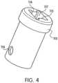
- the lock sleeve 113 shown in Figure 4consists of a tubular proximal sect on, which fits into the distal end of the outer sleeve 112. Retainer hole 116 and apposite retainer hole (not shown) in the lock sleeve 113 receive the retainer tabs 118, 119 ( Figure 6 ).
- the distal end of the lock sleeve 113has a lock sleeve cut-out 117 slightly larger than the cross section of the clip legs ( Figure 3 ). As the clip leg are pulled through cut-out 117, the clip legs are compressed toward each other, thus compressing the tissue (not shown) situated between the clip legs.
- the cut-out 117has lock pawls 114 and 115, which align with the two lock holes ( Figure 3 ) in the clip legs. After the desired tissue purchase has been acquired, the clip can be pulled back far enough to engage the lock pawls 114 and 115 into the two lock holes.
- control wire 108Forming the end of the control wire 108 into a j-hook 107 makes a frangible link shown in Figure 5 .
- This relatively simple configurationeliminates extraneous components that take up space and complicate the assembly.
- the control wire 108is bent such that it wraps around the proximal end of the clip ( Figure 3 ), through a cut-out ( Figure 3 ).
- the retainer release 109operates to release the retainer 10 ( Figure 6 ) from the lock sleeve 113 ( Figure 4 ).
- the retainer release 109pulls the retainer 110 back, disengaging the retainer tabs 118, 119 from the two retainer holes 116 ( Figure 4 ) in which the retainer normally resides.
- the j-hook 107is then straightened by force, in turn releasing the clip.
- the j-hook 107is able to deform to a straightened position (i.e. release) at a predetermined tensile load, which is slightly greater than the load required to grasp the tissue (not shown), compress the tissue, and engage the lock pawls ( Figure 4 ) in the lock holes ( Figure 3 ).
- the control wire 108 shown in Figure 6is a simple stainless steel wire used to actuate the clip 101 via a handle ( Figure 7 ), at the proximal end of the sheath ( Figure 1 ).
- the frangible link(the j-hook 107) is formed in the distal end of the control wire 108 as a one-piece design.
- the proximal end of the control wire 108is terminated inside the handle.
- the control wire 108also has the retainer release 109 formed in it, behind the j-hook 107. The retainer release 109 causes the outer sleeve ( Figure 1 ) to disengage from the retainer 110.
- the handle shown in Figure 7is attached to the proximal end of the sheath 111 at a sheath-handle attachment point 120.
- the handle configurationis unlike a handle found on conventional endoscopic forceps known in the prior art.
- the handleprovides a mechanism by which the amount of linear actuation required in the handle body 121 is greater than that which is translated to the tip of the device ( Figure 1 ).
- actuation of the activator or handle lever 122 of 25.4 mm (1.00 inch)in turn may only move the clip ( Figure 3 ) by 2.54 mm (0.10 inch). This feature allows for a more tactile feel when placing the clip on the vessel (not shown).
- FIG. 8A through 8Eshows a clip with four legs.
- Figure 8Ashows a view from the side, showing clip legs 801.
- This embodimentcould be actuated and released in the same way the previous embodiment is activated and released, through a clip locking mechanism 802.
- the use of a control wirewould actuate the multiple-legged clip in and out of an outer sleeve 803 until such time that the operator desires to release the clip.
- actuation of the control wiremight move the outer sleeve 803 in and out over the multiple-legged clip to open and close the clip legs 801, until such time that the operator desires to release the clip.
- Figure 8Bshows the four-legged clip of Figure 8A from the perspective of the targeted tissue looking proximally.
- the four dip legs 801are shown in an open position and are situated at 90° from each other.
- Figure 8Cshows a profile view of a single clip leg 801.
- Figure 8Dshows a view along the axis of clip locking mechanism 802.
- Figure 8Eshows another view of a four-legged clip with clip legs 801 and clip locking mechanism 802.
- Figure 8Fshows alternative side profiles of the clip geometry. Use of such geometries in a clip with two or more legs allows for improved grasping ability in different situations. Given the large variation in tissue thickness and tissue strength, it is likely that different clip profiles would excel in different procedures.
- Figure 8Gshows alternative end profiles of the clip geometry. As with the varying side profiles, different end profiles would provide a broader range of grasping capabilities.
- Figures 9A and 9Billustrate an alternative embodiment of the device using a different method to lock the clip in the closed position.
- This alternative methoduses an expanded coil spring 901 released over the outside of the clip legs 904 and 905 to lock the clip legs 904 and 905 closed.
- Figure 9Ashows this embodiment in a predeployment state.
- Figure 9Ashows a stretched coil spring 901, twisted to a diameter larger than that of the relaxed state of coil spring 901.
- Stretched coil spring 901is placed over a rigid tube 903 at the distal end of the clip device. Within this rigid tube 903, the clip legs 904 and 905 are free to move in and out (in a manner similar to the manner described for the previous embodiments), between the opened and closed position via a control wire (not shown).
- the sheath 902is used to push the coil spring 901 off of the rigid tube 903, onto the clip legs 904 and 905, as shown in Figure 9B .
- the inward radial forces present in the recovered coil spring 901act to keep the clip legs 904 and 905 compressed.
- FIGs 10A and 10Billustrate another alternative embodiment.
- a flexible linkage 1002 and pill 1003are used to lock the clip legs 1001.
- the clip legs 1001are actuated via a control wire 1006, as described in previous embodiments.
- the clip legsare not closed by pulling the clip legs 1001 through some feature smaller than the open clip. Instead the clip legs 1001 are closed by drawing the two flexible links 1002 proximally, in the direction of the control wire 1006, while a compressive force is applied to the base of the clip legs 1001 by a rigid sheath (not shown). This in turn pulls the legs of the clip toward each other.
- Figure 10Ashows the clip legs 1001 in an open position.
- Figure 10Bshows the clip legs in a closed position.
- the clip legs 1001are locked in a closed position when the pill 1003, located at the center of the flexible linkage 1002, is drawn through a one way hole 1004 in the center of the clip legs 1001.
- the one way hole 1004is tapered, with a diameter slightly larger than the diameter of the pill 1003 on its distal side and a diameter smaller than the diameter of the pill 1003 on its proximal side.
- the pillstretches the material around the hole 1004 as it passes through moving proximally.
- the pill 1003itself can be made of an elastic material and would deform slightly while passing proximally through hole 1004. This funneling effect of the pill 1003 through the hole 1004 only allows the pill 1003 to easily pass through in the locking direction.
- frangible link 1005is a taper in control wire 1006, enabling the link to be broken at a specific position (proximal from the pill 1003) with a predetermined tensile load.
- FIG. 11One alternative to the j-hook type frangible link previously described is shown in Figure 11 .
- This embodimentuses a threaded fitting that is a combination of a male thread 1103 and a female hub 1102 to attach the control wire (not shown) to the clip 1001.
- the clip 1001can be actuated from the opened position (not shown) to the closed position (shown) as described in previous embodiments.
- the lock sleeve 1105is shorter and engages dimples 1106.
- the clip 1101can be released.
- the clip I 101is released when a predetermined tensile load is applied to the male thread 1103, in a similar fashion to the predetermined tensile load applied to straighten the j-hook.
- the female hub 1102may be constructed of a spiral wound wire component with a pitch equal to the thread pitch formed to make the male thread 1103.
- the fit of the threaded componentsis such that the predetermined force will overcome the engaged threads of the male thread 1103 and the female hub 1102, causing them to separate, or "strip" away from one another.
- FIG. 12 A and 12BAnother alternative to the j-hook type frangible link is shown in Figures 12 A and 12B .
- This embodimentuses a ball 1202 fitting into a socket, where the socket is defined by socket tabs 1203, to attach the control wire 1207 to the clip 1201.
- An outer sleeve 1204is attached by way of a breakaway connection (not shown) to the sheath 1206.
- This breakaway connectionmay be a light interference fit, or a light adhesive joint.
- the breakaway connectionmust be weak enough that when the sheath 1206 is pulled back through the working channel (not shown) of the endoscope (not shown), the outer sleeve 1204 will release with the clip 1201.
- the clip 1201is released when the socket tabs 1203 at the proximal end of the clip 1201 are aligned with cut-outs 1205 in the outer sleeve 1204. These cut-outs 1205 act as a relief area into which the socket tabs 1203 can be deformed when a predetermined tensile load is applied to them via the ball 1202 formed on the end of the control wire 1207.
- the outer sleeve 1204is released with clip 1201 so that the clip 1201 remains locked after deployment.
- FIG. 13A , 13B and 13CAnother alternative to the j-hook type frangible link is shown in Figures 13A , 13B and 13C .
- All the figuresshow the clip 1301 in a closed and locked state.
- Figure 13Ashows the clip 1301 in a closed position but before it is released and shows a portion of outer sleeve 1303 cut away to show the internal workings of the clip mechanism.
- Figures 13B and 13Cshow the clip 1301 after being released.
- the actuationis still performed via a control wire 1304, however the direction of action is reversed.
- the clip 1301is closed by the advancement of outer sleeve 1303 and lock ring 1302 over the clip legs.
- the locking sleeve 1302 and clip geometry, including dimples 1306,is the same as that explained in the embodiment of Figure 11 .
- a difference between the embodiment shown in Figures 13A , 13B and 13C and the prior embodimentsis the mechanism by which the clip 1301 is released from the rest of the device.
- An interference fit between the outer sleeve 1303, sheath 1305, and male threaded hub 1308is created when the device is assembled.
- the distal end of the sheath 1305, in its manufactured (but unassembled) statehas an outside diameter greater than the inside diameter of the outer sleeve 1303.
- the distal end of the sheath 1305, again in its manufactured (unassembled) statehas an inside diameter greater than the diameter of the male threaded hub 1308.
- the distal end of the sheath 1305is compressed to fit inside the outer sleeve 1303, it is compressed down onto the male threaded hub 1308 to create a sandwich of the sheath 1305 between the male threaded hub 1308 on the inside and the outer sleeve 1303 on the outside.
- this interference fitis overcome. The interference fit is overcome by advancing the outer sleeve 1303 so far forward, by creating a compressive force in the control wire 1304 in opposition to a tensile force on the sheath 1305, that the outer sleeve 1303 is no longer in contact with the distal end of the sheath 1305.
- the outer sleeve 1303 and the control wire 1304serve two purposes in this embodiment.
- the outer sleeve 1303 and the control wire 1304supply the closing force to the clip 1301.
- a lock ring 1302is used tc maintain the closing force on the clip legs 1307.
- the outer sleeve 1303 and the control wire 1304also act as key components of the release mechanism.
- the end of the sheath 1305is no longer contained within the outer sleeve 1303, and is free to separate from the male threaded hub 1308.
- the sheath 1305is free to release because of the manner in which the distal end of the sheath 1305 is manufactured/assembled.
- the outer sleeve 1303When the outer sleeve 1303 is advanced forward, allowing the distal end of the sheath 1305 to be free, the distal end of the sheath 1305 expands to its original, manufactured state. This allows the inside of the sheath 1305 to release from the male threaded hub 1308.
- the male threaded hub 1308, and thus the clip 1301,are now free from the sheath 1305 and the rest of the delivery device.
- the outer sleeve 1303remains connected to the control wire 1304 a connection point 1310, and both can be removed with the sheath 1305.
- the distal portion of control wire 1304is bent towards, and connects with, outer sleeve 13C 3 at connection point 1310.
- the distal portion of control wire 1304passes male threaded hub 1308 during deployment through slot 1309 in male threaded hub 1308.
- Figures 14A, 14B, and 14Cshow an alternative embodiment.
- the relaxed state of the clipis closed, and it is forced open and allowed to close naturally.
- Figure 14Ashows a side view of the clip 1401 in a closed, pre-released state
- Figure 14Bshows an edge view of the clip 1401 in a closed, pre-released state.
- the primary function of the control wire 1406is changed from having to close the clip 1401, to having to open the clip 1401.
- the clip 1401is manufactured in a generally x-shaped geometry, where each tab 1403 at the proximal end of the clip 1401 controls a clip leg 1407 opposite at the distal end of the clip 1401.
- the action/reaction of the clip 1401is similar to that of a common clothes pin.
- the clip legs 1407are spread apart.
- the clip legs 1407come together.
- a u-ring 1402 attached to the end of the control wire 1406is used to bring the tabs 1403 together, thus openir g the clip 1401.
- control wire 1406Pulling on the control wire 1406 pulls the u-ring 1402 into contact with tabs 1403 creating a compressive force to open clip legs 1407 because clip 1401 is positioned against fulcrum point 1408.
- Advancing control wire 1406advances u-ring 1402, thereby removing the compressive force on tabs 1403 and allowing clip legs 1407 to close.
- Advancing control wire 1406further to a deployment position pushes u-ring 1402 against clip legs 1407, causing clip 1401 to move out of outer sleeve 1404 into a deployed state.
- the control wire 1406is constructed of material having a shape memory, and the distal end of the control wire 1406, where the u-ring 1402 is attached, is pre-bent to one side. While a minimum tension exists in control wire 1406, the u-ring remains around the constriction. However, when the desired location for the clip 1401 has been achieved, and the clip tabs 1403 have been advanced beyond outer sleeve 1404, the control wire 1406 can be advanced to its most distal position. Because the control wire 1406 is pre-bent, as it is advanced the u-ring 1402 becomes disengaged from the clip 1401 when the tension in control wire 1406 falls below a predetermined amount, as shown in Figure 14C . This allows the clip 1401 to be released.
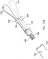
- Figures 15A, 15B, 15C, and 15Dshow another embodiment in which the clip is manufactured in a naturally closed position.
- Figure 15Ashows the distal end of medical device 1509 with the clip 1501 in a closed position before deployment.
- Figure 15Bshows only the clip 1501 in a closed position.
- Figure 15Cshows the clip 1501 in an open position.
- Figure 15Dshows the device after the clip is released.
- the clip 1501is shaped such that, as the control wire 1503 is pulled in a proximal direction, the clip legs 1508 are forced apart from one another. This is accomplished using a pill 1502 attached to the end of the control wire 1503 as explained in previous embodiments.
- the control wire 1503can be advanced to its most distal position. Because the control wire 1503 is constructed of material that has a shape memory, and because the control wire 1503 is pre-bent close to the pill 1502, as the control wire 1503 is advanced, the pill 1502 becomes disengaged from the pill well 1507. When the pill 1502 moves out and away from the pill well 1507, the clip 1501 is released and disengages from the control wire 1502, the sheath 1506, and the outer sleeve 1505.
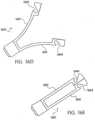
- Figures 16A, 16B, 16C , 16D, and 16Eshow another embodiment in which the clip is manufactured in a naturally closed position.
- Figure 16Ashows the clip 1607 in a closed, predeployed, state.
- Figure 16Bshows a side view of one clip leg 1601 with the pill 1603 still resting in pill well 1604.
- Figure 16Cshows an edge view of one clip leg 1601 with the pill 1603 still resting in pill well 1604.
- Figure 16Dshows a clip 1607 in an open position.
- Figure 16Eshows a clip 1607 in a closed position.
- This embodimentuses two control wires 1605. Alternatively, a branched control wire may be used.
- control wires 1605are disengaged from the clip 1607 by pushing them forward. This action disengages the pills 1603 from the clip 1607 by moving the pills 1603 out of pill wells 1604.
- the control wires 1605are made from a material with a shape memory, so that when freed from pill wells 1604, the pills 1603 move away from the pill wells 1604, and the clip 1607 is deployed.
- FIGS 17A and 17BAnother embodiment is shown in Figures 17A and 17B .
- the control wire or wires 1701are routed to gain mechanical advantage.
- the clip 1702is naturally closed, with the control wire(s) 1701 routed to leverage points 1704 further away from the fulcrum (bending point) 1705 of the c lip 1702.
- the control wire(s) 1701are looped around pins positioned at leverage points 1704 at the ends of the clip legs 1706. The control wire(s) 1701 are then routed to a point at the proximal end of the clip.
- control wire(s) 1701are then terminated at this point
- the control wire(s) 1701could essentially be one, continuous wire, with both ends terminated in the handle (not shown).
- one end of control wire 1701could be detached from the handle and pulled free from the clip 1702. Because the control wire 1701 is only wrapped around pins positioned at leverage points 1704 on the clip 1702, by pulling on one end of control wire 1701, control wire 1701 coulc be easily detached when the desired location for clip 1702 has been achieved by continuing to pull on one end of control wire 1701 until all of control wire 1701 has been detached from the clip 1702.
- Figures 18A, 18B, 18C, 18D, 18E, and 18Fshow an embodiment of a clip which incorporates the natural compressive forces present in a simple elastic band (or o-ring) 1802 to hold the clip legs 1801 in the closed position.
- Figure 18Ashows two clip legs 1801 in a disassembled state.
- Figure 18Bshows a clip with the control wire 1803 engaging a second elastic band 1804 to open clip legs 1801.
- the control wire 1803is attached to the proximal end of the clip legs 1801 via a frangible link.
- the frangible linkis a second elastic band (or o-ring) 1804 that will deform as the control wire 1803 is pulled back.
- the clipis housed in the end of a sheath 1806 such that, as the control wire 1803 is pulled back, the second elastic band 1804 delivers an increasing compressive force to the clip legs 1801 proximal to a pin joint 1805, thereby causing the clip legs 1801 distal from the pin joint to open against the compressive force of elastic band 1802. In this manner, the clip legs 1801 move to an open position, as shown in Figure 18B.
- Figure 18Cshows the clip in a closed, predeployed state.
- Figure 18Dshows a profile view of clip legs 1801
- Figure 18Eshows an end-on view of clip legs 1801 within sheath 1806.
- Figure 18Fshows a close-up view of clip legs 1801 without first elastic band 1802 but showing band slots 1809.
- Figure 18Fshows second elastic band 1804 resting over nubs 1807 and coupled to control wire 1803.
- the second elastic band 1804which makes up the frangible link, is overcome by pulling the control wire 1803 to its most proximal position. This has the effect of breaking second elastic band 1804.
- second elastic band 1804could be designed to release over nubs 1807.
- control wire 1803after placing clip legs 1801 in the desired location, control wire 1803 can be released so that elastic band 1802 again closes clip legs 1801.
- control wire 1803is made of a suitable material, such as a shape memory material, and has a bend in the distal region such that moving control wire 1803 to a maximum distal position acts to unhook hook 1808 from second elastic band 1804.
- FIGS 19A, 19B, and 19Cshow another embodiment utilizing a naturally closed clip.
- Clip 1901is held in the naturally closed position by a torsion spring 1903.
- the clip 1901is actuated from the closed to the opened position in a different way than prior embodiments.
- a plunger 1904located within the outer sleeve 1905 at the end of the sheath (not shown), is used to push on the tabs 1906 on the proximal end of the clip 1901.
- the tabs 1906are pushed through an opening 1907 in the end of the outer sleeve 1905. This moves tabs 1906 close together, in turn moving the clip legs 1902 to the open position.
- the clip 1901can be released by advancing the plunger 1904 to its most distal position.
- Figure 19Bshows the clip 1901 from a profile view.
- Figure 19Cshows a single clip leg 1902 and connection point 1908 for pivotally connecting clip legs 1902 to each other.
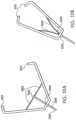
- FIGS 20A, 20B, and 20Cdescribe the embodiment of a three-legged clip and delivery device.
- the clip 2001is manufactured to be in the naturally open position.
- the clip 2001is characterized by male threads 2002 on its outer surface.
- the delivery deviceconsists of a sheath 2003 similar to those described in previous embodiments.
- An inner sleeve 2004 located within the distal end of the sheath 2003is used to actuate the clip 2001 from its naturally open position to the closed position.
- the inner sleeve 2004has female threads (not shown) on its inside diameter.
- a control wire(not shown) is used in this device to transmit rotational force rather than tensile/compressive force. Rotating the sheath 2003 with respect to the control wire, with the handle (not shown) actuates the clip 2001.
- FIG. 20Ashows the clip legs 2005 and inner sleeve 2004 from the perspective of the target area.
- Figure 20Cshows the size relationship between the female threads on the inner sleeve 2004 and the male threads 2002 on the clip 2001.
- the materials utilized in construction of the clip of the present inventioninclude many bio-compatible materials (metals, polymers, composites, etc.).
- a stainless steel grade materialwhich offers good spring properties, may be used.
- the clipcan also be coated, or plated, with a material like gold to improve radiopacity.
- the lock sleeve, lock pawls, retainer and outer sleevemay be comprised of any of the same materials as the clip component.
- stainless steelmay be used.
- the control wire in the first embodimentmay be a stainless steel wire. Because the wire must offer sufficient strength in both tension and compression, the material properties of the wire are important to the functionality of the device. Also, the end of the wire, where the j-hook is formed, must deform when a predetermined tensile load is applied. The device's ability to release the clip is dependent on this property. Other embodiments of the device may incorporate a two (or more) piece wire so that certain sections of the wire have different material properties or geometries. Different material properties or geometries could allow for more control over how and when the wire detaches from the distal tip of the device. This could also be accomplished by several other methods, as well. For example, localized heat treating and/or coatings could be used along portions of the wire to alter the material characteristics. Additionally, some embodiments of the present invention require a control wire constructed of a material with a shape memory.
- the sheathin the first embodiment, is made up of several round, stainless steel wires, wound in a helical pattern to create a hollow, semi-rigid shaft. Sheaths made in this fashion are well known in the prior art. In other embodiments, the sheath could be made up of non-round wires. Other embodiments may be made up of one or more wires formed in a pattern other than a single helix, as in the first embodiment. A multiple helix or braided pattern may be used.
- the sheathmay also be coated with a protective coating of Polytetrafluoroethylene (PT-FE), or similar materials. The use of such coatings could be used to alter the flexibility of the shaft.
- PT-FEPolytetrafluoroethylene
- Such coatingscould also be used to increase the lubricity (decrease the coefficient of friction) between the endoscope working channel and the device. Similar materials could also be used to encapsulate the sheath's base material. This would create a matrix material, providing a combination of material properties not feasible with one single material. Other embodiments may use materials other than stainless steel as the base material. Materials such as titanium, nitinol, and/or nylon fibers may be incorporated.
- a method of using the endoscopic hemostatic clipping deviceinvolves placing an endoscope in a body cavity as is known in the art.
- the device provided hereinis then inserted through the endoscope.
- the endoscopeis positioned near the target area.
- the target areamay be a lesion, a bleeding ulcer, a tumor, other abnormality, or any number of other tissues to be pinched, marked, tagged, or to which the operator wishes to apply a pinching pressure for whatever reason.
- the device providedis then positioned so that the clip legs embrace the target area, then the actuator is activated to close the clip legs. The success or failure of the application of pressure can be reviewed through the optical components provided separately in the endoscope.
- the clip legs of the devicemay be opened by reversing the actuation of the activator.
- the actuatoris fully activated, or the alternative deployment activator is activated. Finally, the remaining portion of the medical device and the endoscope are removed from the body.
Landscapes
- Health & Medical Sciences (AREA)
- Surgery (AREA)
- Life Sciences & Earth Sciences (AREA)
- Heart & Thoracic Surgery (AREA)
- Molecular Biology (AREA)
- Veterinary Medicine (AREA)
- Engineering & Computer Science (AREA)
- Biomedical Technology (AREA)
- Public Health (AREA)
- Medical Informatics (AREA)
- Nuclear Medicine, Radiotherapy & Molecular Imaging (AREA)
- Animal Behavior & Ethology (AREA)
- General Health & Medical Sciences (AREA)
- Reproductive Health (AREA)
- Vascular Medicine (AREA)
- Oral & Maxillofacial Surgery (AREA)
- Pathology (AREA)
- Surgical Instruments (AREA)
Description
- The present Invention relates to compression clips, and more specifically, to compression clips used to cause hemostasis of blood vessels located along the gastrointestinal tract delivered to a target site through an endoscope.
- Gastrointestinal ("GI") bleeding is often associated with peptic ulcer disease (PUD) and can be fatal if not treated immediately. Hemorrhaging is the most dangerous procedure with which a Gastro-Intestinal Endoscopist has to deal. It is his/her only unplanned, emergency procedure where time is critical in determining the outcome. It is also the one problem the Endoscopist faces that is generally not an outpatient procedure. A bleeding PUD can be a critical clinical event as there is internal hemorrhaging. Ulcers are classified from clean to active spurting bleeding. The most worrisome are active bleeders and visible vessels. Untreated visible vessels are likely to bleed.
- Suspected bleeding PUD patients can be diagnosed and treated endoscopically in an emergency room, an ICU or the GI suite. Surgery generally results in higher cost, morbidity and mortality than endoscopy. Therefore, laparoscopy or open surgery is not preferred unless there is no endoscopic alternative or endoscopy has failed. If the diseased tissue is beyond repair, a surgical gastric resection may be performed.
- Currently, the endoscopist has two commonly used treatments and some lesser used therapies to achieve hemostasis of the ulcer. The most widely used treatments are thermal therapy and injection therapy. Some of the less common options are Olympus Endoclips, lasers and argon plasma cautery.
- With thermal therapy, a catheter with a rigid heating element tip is passed through the working channel of an endoscope after the bleed is visualized and diagnosed. After the rigid catheter tip has exited the scope, the scope is manipulated to press the tip against the bleed site. Thermal power is applied, either through a resistive element in the tip or by applying RF energy through the tissue, thus desiccating and cauterizing the tissue. The combination of the tip compressing the tissue/vessel and the application of heat theoretically welds the vessel closed.
- Although thermal treatment is fairly successful in achieving hemostasis, it often takes more than one attempt (irrigation is applied after the initial treatment to see if hemostasis has occurred) and there is frequent re-bleeding. Generally several pulses of energy are applied during each attempt. If early re-treatment is needed, there is a risk of perforation with the heat probe. Another disadvantage is that both types of thermal therapy require a specialized power generator and the equipment can be expensive.
- With injection therapy, a catheter with a distally extendable hypo needle is passed through the working channel of the endoscope after the bleeding has been visualized and diagnosed. Once the catheter tip has exited the scope, the scope is manipulated to the bleed site, the needle is extended remotely and inserted into the bleed site. A vasoconstricting (narrowing of blood vessels) or sclerosing (causing a hardening of tissue) drug is then injected through the needle. Multiple injections in and around the bleeding site are often needed, until hemostasis has been achieved. As with thermal therapy, re-bleeding is also a problem.
- The treatment used in any specific instance is highly dependent on geographic region. In some regions, especially in the United States, injection therapy is often combined with thermal treatment since neither therapy is completely effective alone.
- The primary success rate of endoscopic treatment is about 90%. The other cases are usually referred to surgery. All identified ulcers may re-bleed at a later time, but the re-bleed rate for endoscopically treated active bleeds and a visible vessel is 10-30%. Even with the introduction of new treatments and devices, these rates have not improved significantly in decades. Surgery's short and long-term success for permanent hemostasis is virtually 100%.
- Surgery has a higher success rate because the bleeding site is compressed mechanically, causing better hemostasis. Using devices such as clamps, clips, staples, sutures (i.e. devices able to apply sufficient constrictive forces to blood vessels so as to limit or interrupt blood flow), the bleeding vessel is ligated or the tissue around the bleed site is compressed, ligating all of the surrounding vessels.
- An existing device that incorporates the advantages of surgery into a less-invasive endoscopic procedure is the Olympus EndoClip. The goal of the device is to pinch the bleeding vessel to create hemostasis. The problem with this device is that once jaw closure begins, it is not possible to reopen them, and the endoscopist is committed to firing the clip. In other words, jaw closure is not reversible. Because the vessel is frequently difficult to see, often several clips must be deployed in order to successfully pinch the vessel and achieve hemostasis. Additionally, the Olympus EndoClip is a semi-reusable device, causing the performance of the device to degrade with use.
US 3 958 576 A discloses a clip member that is detachably attached to an instrument body. The instrument body has an outer flexible tube, an actuating tubular member inserted into the outer tube, and a wire inserted into the actuating tubular member. A holder is detachably mounted through a guide member to the forward end portion of the actuating member. To the forward end of the wire is secured a hook member for anchoring the clip member. A pair of clamping portions of the clip member is opened by forcefully engaging a pair of offset portions of the clip member with the inner surface of the holder, and closed by forcefully engaging a pair of intersecting portions with the inner surface of the holder. The clip member, together with the holder, is left within the body cavity with the clamping portions thereof closed.US 5 520 701 A discloses a set for the treatment of vascular deformation including a clamp made from titanium. The clamp is expanded in the relieved state and is transferable into the clamping position by a clamping ring, which is displaceable along the clamp in the attached state. The clamp is introduced into the body by a probe, which has a tubular casing and a positioning bar guided therein.JP H05 208020 A - The device of the present invention is defined in
independent claim 1. Preferred embodiments are defined in the dependent claims. - The present invention provides medical devices for causing the hemostasis of blood vessels located along the gastrointestinal tract. The goal of the invention is to give the endoscopist a technique and device which: 1) has a success rate in line with the surgical option; 2) is easier to set-up than the Olympus EndoClip; and 3) is easier to deploy than the Olympus EndoClip. The design intent is to eliminate surgery and its associated mortality and morbidity.
- The medical devices of the present invention include: a compression clip used to cause hemostasis of blood vessels and a mechanism for deploying the clip that includes an arrangement for closing the clip and for reversing the closing process to reopen the clip after closure has begun. Embodiments of the invention may include a lock arrangement for locking the clip closed; a control wire connected to the clip and able to be disconnected from the dip; an axially rigid sheath enclosing the control wire and communicating a compressive force opposing a tensile force of the control wire; a handle connected to the axially rigid sheath; and/or a trigger enclosed within the handle and engaging the control wire to close and lock the clip and to uncouple the control wire from the clip.
- There are several key advantages of the invention disclosed here over existing devices. The device's ability to repeatedly open and close the clip until the desired tissue pinching is accomplished will lead to a quicker procedure, requiring less clips to be deployed, with a higher success rate. In particular embodiments, this higher success rate will be improved even more due to the device's ability to be easily rotated so that the clip legs can be adjusted relative to the bleeding vessel. In particular embodiments, the time required to perform the overall procedure will also be further reduced due to the fact that the device is completely set up, with the clip already attached to the delivery device, unlike the competitive device. A more robust delivery device may allow a larger, stronger clip to be delivered. Combinations of these features will provide for a device that is easier to use.
- Another advantage inherent to particular embodiments of this design is the feature of being completely disposable. The competitive device, the Olympus Endoclip, uses a "semi-reusable" delivery device, capable of firing several clips before it fails. This causes the device's functionality to degrade over the course of its use, until it is no longer able to deploy a clip. The competitive delivery device must be loaded manually, which is cumbersome to the operator and time-consuming, especially in the context of an unplanned emergency procedure. The "single-use" (disposable) embodiments of the invention disclosed here would function the same with each clip, in each procedure.
Fig. 1-7 disclose an embodiment of the invention.Figure 1 is an enlarged partial view of a first embodiment of the medical device of the present invention.Figure 2 is an enlarged partial view of the distal end of the embodiment ofFigure 1 .Figure 3 is an enlarged view of the clip of the embodiment ofFigure 1 .Figure 4 is an enlarged view of the lock sleeve of the embodiment ofFigure 1 .Figure 5 is an enlarged view of the j-hook of the embodiment ofFigure 1 .Figure 6 is an enlarged partial view of the control wire, retainer, and clip of the embodiment ofFigure 1 .Figure 7 is an enlarged partial view of the handle of the embodiment ofFigure 1 .Figure 8A is an enlarged partial view of a distal end available for use in another embodiment of the medical device of the present invention.Figure 8B is an enlarged partial end view of the distal end ofFigure 8A .Figure 8C is an enlarged partial view of a clip leg of the embodiment ofFigure 8A .Figure 8D is an enlarged partial view of a clip locking mechanism of the embodiment ofFigure 8A .Figure 8E is an enlarged partial view of a clip locking mechanism and clip legs of the embodiment ofFigure 8A .Figure 8F shows enlarged partial side views of various embodiments of clip leg shapes available for use in the medical device of the present invention.Figure 8G shows enlarged partial end views of various embodiments of clip leg shapes available for use in the medical device of the present invention.Figure 9A is an enlarged partial view of the distal end of another medical device.Figure 9B is an enlarged partial view of the embodiment ofFigure 9A being deployed.Figure 10A is an enlarged partial view of another medical device.Figure 10B is an enlarged partial view of the embodiment ofFigure 10A being deployed.Figure 11 is an enlarged partial view of another medical device.Figure 12A is an enlarged partial view of another medical device showing the clip in an open position.Figure 12B is an enlarged partial view of the embodiment ofFigure 12A showing the clip in a closed position.Figure 13A is an enlarged partial view of another medical device showing the clip in a closed position prior to disconnecting the clip.Figure 13B is an enlarged partial view of the distal end of the embodiment ofFigure 13A showing the clip in a closed position after disconnecting the clip.Figure 13C is an enlarged partial view of the embodiment ofFigure 13A showing the clip in a closed position after disconnecting the clip.Figure 14A is an enlarged partial view of another medical device.Figure 14B is an enlarged partial side view of the embodiment ofFigure 14A .Figure 14C is an enlarged partial view of the distal end of the medical device of the embodiment ofFigure 14A after the clip has been released.Figure 15A is an enlarged partial view of another medical device.Figure 15B is an enlarged partial view of the clip of the embodiment ofFigure 15A in a closed position.Figure 15C is an enlarged partial view of the clip of the embodiment ofFigure 15A in an open position.Figure 15D is an enlarged partial view of the distal end of the medical device of the embodiment ofFigure 15A after the clip has been released.Figure 16A is an enlarged partial view of another medical device.Figure 16B is an enlarged partial close-up side view of the end of a clip leg of the embodiment ofFigure 16A .Figure 16C is an enlarged partial close-up edge view of the end of a clip leg of the embodiment ofFigure 16A .Figure 16D is an enlarged partial view of the embodiment ofFigure 16A with the clip in an open position.Figure 16E is an enlarged partial view of the embodiment ofFigure 16A with the clip in a closed position.Figure 17A is an enlarged partial view of another medical device.Figure 17B is an enlarged partial view of the embodiment ofFigure 17A , showing the clip in an open position.Figure 18A is an enlarged view of clip legs of another medical device.Figure 18B is an enlarged partial view of a further medical device using the clip legs ofFigure 18A .Figure 18C is an enlarged partial view of the embodiment ofFigure 18B , showing the clip in a closed position.Figure 18D Is an enlarged edge view of the clip of the embodiment ofFigure 18B .Figure 18E is an enlarged partial end view of the embodiment ofFigure 18B .Figure 18F is an enlarged partial side view of the embodiment ofFigure 18B .Figure 19A is an enlarged partial edge view of another medical device.Figure 19B is an enlarged partial side view of the embodiment ofFigure 9A .Figure 19C is an enlarged partial view of a clip leg of the embodiment ofFigure 19A .Figure 20A is an enlarged partial end view of another medical device.Figure 20B is an enlarged partial side view of the embodiment ofFigure 20A .Figure 20C is a side-by-side comparison of two parts of the embodiment ofFigure 20A .- In a first embodiment of the invention as shown in
Figure 1 ,medical device 100 includes aclip 101 havingfirst clip leg 102 andsecond clip leg 103.Clip leg 102 has at least onelock hole 104 therein of any suitable shape (e.g. circular, rectangular, square, etc.). Likewise,clip leg 103 has at least onelock hole 105 therein of any suitable shape.Clip 101 is further characterized by a cut-out 106 on the proximal end. J-hook 107 is inserted into cut-out 106. J-hook 107 is formec on the distal terminal end ofcontrol wire 108. Aretainer release 109 is formed by bends in thecontrol wire 108, the bends formed proximally from the j-hook 107. Thecontrol wire 108 is enclosed withinsheath 111 proximally from theretainer release 109.Retainer 110 is coupled to controlwire 108 and engageslock sleeve 113.Retainer release 109 acts to disengageretainer 110 fromlock sleeve 113 when a tensile force applied to controlwire 108 is sufficient to cause such disengagement. Anouter sleeve 112 is connected on the distal side ofsheath 111, and locksleeve 113 is connected to a distal side ofouter sleeve 112.Lock sleeve 113 incorporateslock pawl 114, which engageslock hole 104 inclip leg 102, and lockpawl 115, which engageslock hole 105 inclip leg 103. - The
clip 101 is a deformable, multi-legged, grasping device attached to the distal portion of a flexible shaft (the sheath 111) via a frangible link (the j-hook 107). The flexible shaft is connected at its proximal end to a handle (Figure 7 ), the handle analogous to biopsy forceps. A semi-rigid wire (the control wire 108), which is routed from the handle to theclip 101, acts as a means of actuating theclip 101 between the open and closed position. Theclip 101 can be actuated between tie open and closed position multiple times as long as the lock holes 104 and 105 do not become engaged with thelock pawls lock sleeve 113. Once the operator decides theclip 101 should be permanently deployed, the handle can be fully actuated, which causes theretainer release 109 to pull theretainer 110 free from theouter sleeve 112 and locksleeve 113. After theretainer 110 is released, increasing force will begin straightening the j-hook 107. The j-hook 107 is then pulled from the cut-out 106 on the proximal side ofclip 101. At this point, theretainer 110 andcontrol wire 108 are no longer attached to the distal portion of the device (theclip 101 and lock sleeve 113) and the delivery device (e.g. an endoscope, not shown) can be removed while leaving the clip 101 (with lock sleeve 113) in place. - The
sheath 111 serves three key functions in this embodiment. In its primary function it acts as a housing for thecontrol wire 108. In this function thesheath 111 supplies a resistive, compressive force opposite the tensile force applied to thecontrol wire 108, via the handle, as the lever (Figure 7 ) in the handle is moved to close theclip 101. The forces reverse when the lever is moved in the opposite direction, and thecontrol wire 108 is compressed to push theclip 101 forward. In this function, the combination ofcontrol wire 108 andsheath 111 act as a simple push-pull, cable actuation mechanism. - In the secondary function of
sheath 111, it acts as a means by which theclip 101 can be easily rotated. Ideally this rotation would be of a ratio of 1:1. In other words, one complete rotation of thesheath 111 at the proximal end would translate to one complete rotation of theclip 101. This rotation however, depends on several factors. The relationship of the outside diameter ofsheath 111 to the inside diameter of the working channel (not shown) of the endoscope (not shown), is one factor. Another factor is the amount of friction between thesheath 111 and the working channel caused by the path of the endoscope in the anatomy. Because these factors vary from endoscope to endoscope, and patient to patient, the rotation ratio will not always be the same. This ease of rotation is a key function and benefit of this embodiment in that it allows relatively precise orientation of theclip 101 to the vessel. Depending on the exact construction of thesheath 111, and the other factors just listed, rotation of the device may be different in one direction of rotation versus the other direction. By taking advantage of the mechanical properties of thesheath 111, this embodiment accomplishes rotation without the need for additional handle components. Eliminating the need for such components will: reduce the overall cost of the device; simplify how the device is operated; and make rotation more repeatable. In turn, all of these benefits will make for a faster procedure with a higher success rate. - The
sheath 111 accomplishes a high rotation ratio by using a spiral wound, multiple-wire, stainless steel, flexible shaft, with an outside diameter of slightly less than the inside diameter of the working channel of the endoscope. Because thesheath 111 is made of a multiple-wire configuration, it is soft and bendable, yet rigid in rotation. In other words, thesheath 111 is flexible enough to be manipulated through a flexible endoscope, but has a very low angle of twist about its central axis. - In the third function of the
sheath 111, it acts as a component of the mechanism by which theclip 101 is released. Theouter sleeve 112, which is rigidly attached to thesheath 111 by methods known in the prior art (e.g. adhesives, welding, swaging, etc.), is made of a rigid tube, with two retainer cut-outs (not shown), situated 180° apart from each other. These retainer cut-outs house the twotabs 118, 119 (Figure 6 ) of theretainer 110. As thecontrol wire 108 is actuated drawing theclip 101 back into thelock sleeve 113, theretainer release 109 forces theretainer 110 to be disengaged from theouter sleeve 112. Figure 2 shows theclip 101 in the closed position but prior to release of the j-hook 107. In the closed, locked position shown inFigure 2 ,lock hole 104 ofclip leg 102 is engaged bylock pawl 114, and lockhole 105 ofclip leg 103 is engaged bylock pawl 115. The fit between thelock sleeve 113 andouter sleeve 112 is such that the lock sleeve 113 (and therefore the clip 101) will easily release from theouter sleeve 112 once the j-hook 107 has been straightened and the retainer disengaged from theouter sleeve 112.- The
clip 101, shown inFigure 3 , is manufactured of a single piece of stainless steel, or any suitable biocompatible material, and is bent into a two-legged geometry. Theclip legs lock hole 104 inclip leg 102 andlock hole 105 inclip leg 103. The interface between the lock holes and the lock pawls creates the mechanical lock that will keep theclip 101 closed after deployment. The proximal end of theclip 101 is formed with a cut-out 106 into which the j-hook (Figure 2 ) is attached. - The
lock sleeve 113 shown inFigure 4 consists of a tubular proximal sect on, which fits into the distal end of theouter sleeve 112.Retainer hole 116 and apposite retainer hole (not shown) in thelock sleeve 113 receive theretainer tabs 118, 119 (Figure 6 ). The distal end of thelock sleeve 113 has a lock sleeve cut-out 117 slightly larger than the cross section of the clip legs (Figure 3 ). As the clip leg are pulled through cut-out 117, the clip legs are compressed toward each other, thus compressing the tissue (not shown) situated between the clip legs. The cut-out 117 haslock pawls Figure 3 ) in the clip legs. After the desired tissue purchase has been acquired, the clip can be pulled back far enough to engage thelock pawls - Forming the end of the
control wire 108 into a j-hook 107 makes a frangible link shown inFigure 5 . This relatively simple configuration eliminates extraneous components that take up space and complicate the assembly. Thecontrol wire 108 is bent such that it wraps around the proximal end of the clip (Figure 3 ), through a cut-out (Figure 3 ). Another bend in the wire, proximal to the j-hook 107, acts as aretainer release 109. Theretainer release 109 operates to release the retainer 10 (Figure 6 ) from the lock sleeve 113 (Figure 4 ). As thecontrol wire 108 is actuated and the clip is locked into the lock sleeve, theretainer release 109 pulls theretainer 110 back, disengaging theretainer tabs Figure 4 ) in which the retainer normally resides. After this disengagement is complete, the j-hook 107 is then straightened by force, in turn releasing the clip. The j-hook 107 is able to deform to a straightened position (i.e. release) at a predetermined tensile load, which is slightly greater than the load required to grasp the tissue (not shown), compress the tissue, and engage the lock pawls (Figure 4 ) in the lock holes (Figure 3 ). - The
control wire 108 shown inFigure 6 is a simple stainless steel wire used to actuate theclip 101 via a handle (Figure 7 ), at the proximal end of the sheath (Figure 1 ). In this embodiment of the invention, the frangible link (the j-hook 107) is formed in the distal end of thecontrol wire 108 as a one-piece design. The proximal end of thecontrol wire 108 is terminated inside the handle. Thecontrol wire 108 also has theretainer release 109 formed in it, behind the j-hook 107. Theretainer release 109 causes the outer sleeve (Figure 1 ) to disengage from theretainer 110. This is done sequentially, after the lock holes (Figure 3 ) in theclip 101 have engaged the lock sleeve (Figure 4 ). After the lock holes engage the lock sleeve, tensile force applied to controlwire 108 first straightens j-hook 107 so that j-hook 107 releases from cut-out 106, thenretainer release 109 engages and deformsretainer 110 so thatretainer tabs Figure 1 ) and the lock sleeve (Figure 4 ). Alternatively,retainer release 109 could engage and deformretainer 110 before j-hook 106 straightens and disengages from cut-out 106. - The handle shown in
Figure 7 is attached to the proximal end of thesheath 111 at a sheath-handle attachment point 120. The handle configuration is unlike a handle found on conventional endoscopic forceps known in the prior art. The handle provides a mechanism by which the amount of linear actuation required in thehandle body 121 is greater than that which is translated to the tip of the device (Figure 1 ). In other words, actuation of the activator or handlelever 122 of 25.4 mm (1.00 inch) in turn may only move the clip (Figure 3 ) by 2.54 mm (0.10 inch). This feature allows for a more tactile feel when placing the clip on the vessel (not shown). In effect, very subtle amounts of movement in the clip can be accomplished by more exaggerated, less precise movements of the operator's hand. This is accomplished because the activator orlever 122 pivots about apivot point 123 that is close to theattachment point 124 of thecontrol wire 125. - An alternative embodiment of the device may be made up of clips with more than two legs.
Figures 8A through 8E shows a clip with four legs.Figure 8A shows a view from the side, showingclip legs 801. This embodiment could be actuated and released in the same way the previous embodiment is activated and released, through aclip locking mechanism 802. The use of a control wire (not shown) would actuate the multiple-legged clip in and out of an outer sleeve 803 until such time that the operator desires to release the clip. Alternatively, actuation of the control wire might move the outer sleeve 803 in and out over the multiple-legged clip to open and close theclip legs 801, until such time that the operator desires to release the clip.Figure 8B shows the four-legged clip ofFigure 8A from the perspective of the targeted tissue looking proximally. The fourdip legs 801 are shown in an open position and are situated at 90° from each other.Figure 8C shows a profile view of asingle clip leg 801.Figure 8D shows a view along the axis ofclip locking mechanism 802.Figure 8E shows another view of a four-legged clip withclip legs 801 andclip locking mechanism 802. Figure 8F shows alternative side profiles of the clip geometry. Use of such geometries in a clip with two or more legs allows for improved grasping ability in different situations. Given the large variation in tissue thickness and tissue strength, it is likely that different clip profiles would excel in different procedures.Figure 8G shows alternative end profiles of the clip geometry. As with the varying side profiles, different end profiles would provide a broader range of grasping capabilities.Figures 9A and 9B illustrate an alternative embodiment of the device using a different method to lock the clip in the closed position. This alternative method uses an expandedcoil spring 901 released over the outside of theclip legs clip legs Figure 9A shows this embodiment in a predeployment state.Figure 9A shows a stretchedcoil spring 901, twisted to a diameter larger than that of the relaxed state ofcoil spring 901. Stretchedcoil spring 901 is placed over arigid tube 903 at the distal end of the clip device. Within thisrigid tube 903, theclip legs sheath 902 is used to push thecoil spring 901 off of therigid tube 903, onto theclip legs Figure 9B . The inward radial forces present in the recoveredcoil spring 901 act to keep theclip legs Figures 10A and 10B illustrate another alternative embodiment. In this embodiment, aflexible linkage 1002 andpill 1003 are used to lock theclip legs 1001. In this embodiment theclip legs 1001 are actuated via acontrol wire 1006, as described in previous embodiments. However, in this embodiment, the clip legs are not closed by pulling theclip legs 1001 through some feature smaller than the open clip. Instead theclip legs 1001 are closed by drawing the twoflexible links 1002 proximally, in the direction of thecontrol wire 1006, while a compressive force is applied to the base of theclip legs 1001 by a rigid sheath (not shown). This in turn pulls the legs of the clip toward each other.Figure 10A shows theclip legs 1001 in an open position.Figure 10B shows the clip legs in a closed position. Theclip legs 1001 are locked in a closed position when thepill 1003, located at the center of theflexible linkage 1002, is drawn through a oneway hole 1004 in the center of theclip legs 1001. The oneway hole 1004 is tapered, with a diameter slightly larger than the diameter of thepill 1003 on its distal side and a diameter smaller than the diameter of thepill 1003 on its proximal side. The pill stretches the material around thehole 1004 as it passes through moving proximally. Alternatively, thepill 1003 itself can be made of an elastic material and would deform slightly while passing proximally throughhole 1004. This funneling effect of thepill 1003 through thehole 1004 only allows thepill 1003 to easily pass through in the locking direction. This locking action is maintained after the clip is released by positioning thefrangible link 1005 in a proximal direction oncontrol wire 1006 from thepill 1003, thus maintaning tissue compression. In this embodiment thefrangible link 1005 is a taper incontrol wire 1006, enabling the link to be broken at a specific position (proximal from the pill 1003) with a predetermined tensile load.- One alternative to the j-hook type frangible link previously described is shown in
Figure 11 . This embodiment uses a threaded fitting that is a combination of amale thread 1103 and afemale hub 1102 to attach the control wire (not shown) to theclip 1001. Theclip 1001 can be actuated from the opened position (not shown) to the closed position (shown) as described in previous embodiments. In this embodiment, thelock sleeve 1105 is shorter and engagesdimples 1106. After the lesion (not shown) is properly targeted, theclip 1101 can be released. The clip I 101 is released when a predetermined tensile load is applied to themale thread 1103, in a similar fashion to the predetermined tensile load applied to straighten the j-hook. This force causes themale thread 1103 to detach from thefemale hub 1102. Thefemale hub 1102 may be constructed of a spiral wound wire component with a pitch equal to the thread pitch formed to make themale thread 1103. The fit of the threaded components is such that the predetermined force will overcome the engaged threads of themale thread 1103 and thefemale hub 1102, causing them to separate, or "strip" away from one another. - Another alternative to the j-hook type frangible link is shown in
Figures 12 A and 12B . This embodiment uses aball 1202 fitting into a socket, where the socket is defined bysocket tabs 1203, to attach thecontrol wire 1207 to theclip 1201. Anouter sleeve 1204 is attached by way of a breakaway connection (not shown) to thesheath 1206. This breakaway connection may be a light interference fit, or a light adhesive joint. The breakaway connection must be weak enough that when thesheath 1206 is pulled back through the working channel (not shown) of the endoscope (not shown), theouter sleeve 1204 will release with theclip 1201. Theclip 1201 is released when thesocket tabs 1203 at the proximal end of theclip 1201 are aligned with cut-outs 1205 in theouter sleeve 1204. These cut-outs 1205 act as a relief area into which thesocket tabs 1203 can be deformed when a predetermined tensile load is applied to them via theball 1202 formed on the end of thecontrol wire 1207. Theouter sleeve 1204 is released withclip 1201 so that theclip 1201 remains locked after deployment. - Another alternative to the j-hook type frangible link is shown in
Figures 13A ,13B and13C . All the figures show theclip 1301 in a closed and locked state.Figure 13A shows theclip 1301 in a closed position but before it is released and shows a portion ofouter sleeve 1303 cut away to show the internal workings of the clip mechanism.Figures 13B and13C show theclip 1301 after being released. In this embodiment, the actuation is still performed via acontrol wire 1304, however the direction of action is reversed. As thecontrol wire 1304 is pushed forward, theclip 1301 is closed by the advancement ofouter sleeve 1303 andlock ring 1302 over the clip legs. Thelocking sleeve 1302 and clip geometry, includingdimples 1306, is the same as that explained in the embodiment ofFigure 11 . - A difference between the embodiment shown in
Figures 13A ,13B and13C and the prior embodiments is the mechanism by which theclip 1301 is released from the rest of the device. An interference fit between theouter sleeve 1303,sheath 1305, and male threadedhub 1308 is created when the device is assembled. The distal end of thesheath 1305, in its manufactured (but unassembled) state, has an outside diameter greater than the inside diameter of theouter sleeve 1303. When theouter sleeve 1303 andsheath 1305 are assembled together part of the interference fit is created. The distal end of thesheath 1305, again in its manufactured (unassembled) state, has an inside diameter greater than the diameter of the male threadedhub 1308. During assembly, as the distal end of thesheath 1305 is compressed to fit inside theouter sleeve 1303, it is compressed down onto the male threadedhub 1308 to create a sandwich of thesheath 1305 between the male threadedhub 1308 on the inside and theouter sleeve 1303 on the outside. During the medical procedure, at the time the operator wishes to release theclip 1301, this interference fit is overcome. The interference fit is overcome by advancing theouter sleeve 1303 so far forward, by creating a compressive force in thecontrol wire 1304 in opposition to a tensile force on thesheath 1305, that theouter sleeve 1303 is no longer in contact with the distal end of thesheath 1305. - The
outer sleeve 1303 and thecontrol wire 1304 serve two purposes in this embodiment. Theouter sleeve 1303 and thecontrol wire 1304 supply the closing force to theclip 1301. InFigures 13A ,13B , and13C , alock ring 1302 is used tc maintain the closing force on theclip legs 1307. Theouter sleeve 1303 and thecontrol wire 1304 also act as key components of the release mechanism. As previously described, once theouter sleeve 1303 is moved to its forward-most position, the end of thesheath 1305 is no longer contained within theouter sleeve 1303, and is free to separate from the male threadedhub 1308. Thesheath 1305 is free to release because of the manner in which the distal end of thesheath 1305 is manufactured/assembled. - When the
outer sleeve 1303 is advanced forward, allowing the distal end of thesheath 1305 to be free, the distal end of thesheath 1305 expands to its original, manufactured state. This allows the inside of thesheath 1305 to release from the male threadedhub 1308. The male threadedhub 1308, and thus theclip 1301, are now free from thesheath 1305 and the rest of the delivery device. As shown inFigure 13C , theouter sleeve 1303 remains connected to the control wire 1304 aconnection point 1310, and both can be removed with thesheath 1305. The distal portion ofcontrol wire 1304 is bent towards, and connects with, outer sleeve 13C 3 atconnection point 1310. The distal portion ofcontrol wire 1304 passes male threadedhub 1308 during deployment throughslot 1309 in male threadedhub 1308. Figures 14A, 14B, and 14C show an alternative embodiment. In the embodiment ofFigures 14A, 14B, and 14C , the relaxed state of the clip is closed, and it is forced open and allowed to close naturally.Figure 14A shows a side view of theclip 1401 in a closed, pre-released state, andFigure 14B shows an edge view of theclip 1401 in a closed, pre-released state. In this embodiment, because theclip 1401 is manufactured such that theclip legs 1407 are naturally closed, the primary function of thecontrol wire 1406 is changed from having to close theclip 1401, to having to open theclip 1401. Theclip 1401 is manufactured in a generally x-shaped geometry, where eachtab 1403 at the proximal end of theclip 1401 controls aclip leg 1407 opposite at the distal end of theclip 1401. The action/reaction of theclip 1401 is similar to that of a common clothes pin. As thetabs 1403 are brought together, theclip legs 1407 are spread apart. As thetabs 1403 are released, theclip legs 1407 come together. A u-ring 1402 attached to the end of thecontrol wire 1406 is used to bring thetabs 1403 together, thus openir g theclip 1401. Pulling on thecontrol wire 1406 pulls the u-ring 1402 into contact withtabs 1403 creating a compressive force to openclip legs 1407 becauseclip 1401 is positioned againstfulcrum point 1408. Advancingcontrol wire 1406 advances u-ring 1402, thereby removing the compressive force ontabs 1403 and allowingclip legs 1407 to close. Advancingcontrol wire 1406 further to a deployment position pushes u-ring 1402 againstclip legs 1407, causingclip 1401 to move out ofouter sleeve 1404 into a deployed state.- The
control wire 1406 is constructed of material having a shape memory, and the distal end of thecontrol wire 1406, where the u-ring 1402 is attached, is pre-bent to one side. While a minimum tension exists incontrol wire 1406, the u-ring remains around the constriction. However, when the desired location for theclip 1401 has been achieved, and theclip tabs 1403 have been advanced beyondouter sleeve 1404, thecontrol wire 1406 can be advanced to its most distal position. Because thecontrol wire 1406 is pre-bent, as it is advanced the u-ring 1402 becomes disengaged from theclip 1401 when the tension incontrol wire 1406 falls below a predetermined amount, as shown inFigure 14C . This allows theclip 1401 to be released. Figures 15A, 15B, 15C, and 15D show another embodiment in which the clip is manufactured in a naturally closed position.Figure 15A shows the distal end of medical device 1509 with theclip 1501 in a closed position before deployment.Figure 15B shows only theclip 1501 in a closed position.Figure 15C shows theclip 1501 in an open position.Figure 15D shows the device after the clip is released. Theclip 1501 is shaped such that, as thecontrol wire 1503 is pulled in a proximal direction, theclip legs 1508 are forced apart from one another. This is accomplished using apill 1502 attached to the end of thecontrol wire 1503 as explained in previous embodiments. Tworigid arms 1504, located between theclip legs 1508, translate the tensile force on thecontrol wire 1503 to an outward radial force on theclip legs 1508. When the desired location for theclip 1501 has been achieved, thecontrol wire 1503 can be advanced to its most distal position. Because thecontrol wire 1503 is constructed of material that has a shape memory, and because thecontrol wire 1503 is pre-bent close to thepill 1502, as thecontrol wire 1503 is advanced, thepill 1502 becomes disengaged from thepill well 1507. When thepill 1502 moves out and away from thepill well 1507, theclip 1501 is released and disengages from thecontrol wire 1502, thesheath 1506, and theouter sleeve 1505.Figures 16A, 16B, 16C ,16D, and 16E show another embodiment in which the clip is manufactured in a naturally closed position.Figure 16A shows theclip 1607 in a closed, predeployed, state.Figure 16B shows a side view of oneclip leg 1601 with thepill 1603 still resting inpill well 1604.Figure 16C shows an edge view of oneclip leg 1601 with thepill 1603 still resting inpill well 1604.Figure 16D shows aclip 1607 in an open position.Figure 16E shows aclip 1607 in a closed position. This embodiment uses twocontrol wires 1605. Alternatively, a branched control wire may be used. By using a branched control wire or two control wires the force can be transmitted to a point further away from the fulcrum (bending point) 1606 of theclip 1607. The greater this distance, the lesser the force required to open theclip legs 1601. As in the previous embodiments, thecontrol wires 1605 are disengaged from theclip 1607 by pushing them forward. This action disengages thepills 1603 from theclip 1607 by moving thepills 1603 out ofpill wells 1604. Thecontrol wires 1605 are made from a material with a shape memory, so that when freed frompill wells 1604, thepills 1603 move away from thepill wells 1604, and theclip 1607 is deployed.- Another embodiment is shown in
Figures 17A and 17B . In this embodime nt, the control wire orwires 1701 are routed to gain mechanical advantage. In this embodiment, theclip 1702 is naturally closed, with the control wire(s) 1701 routed to leveragepoints 1704 further away from the fulcrum (bending point) 1705 of thec lip 1702. In this embodiment, the control wire(s) 1701 are looped around pins positioned atleverage points 1704 at the ends of theclip legs 1706. The control wire(s) 1701 are then routed to a point at the proximal end of the clip. The control wire(s) 1701 are then terminated at this point For ease of manufacture, the control wire(s) 1701 could essentially be one, continuous wire, with both ends terminated in the handle (not shown). To release theclip 1702, one end ofcontrol wire 1701 could be detached from the handle and pulled free from theclip 1702. Because thecontrol wire 1701 is only wrapped around pins positioned atleverage points 1704 on theclip 1702, by pulling on one end ofcontrol wire 1701,control wire 1701 coulc be easily detached when the desired location forclip 1702 has been achieved by continuing to pull on one end ofcontrol wire 1701 until all ofcontrol wire 1701 has been detached from theclip 1702. Figures 18A, 18B, 18C, 18D, 18E, and 18F show an embodiment of a clip which incorporates the natural compressive forces present in a simple elastic band (or o-ring) 1802 to hold theclip legs 1801 in the closed position.Figure 18A shows twoclip legs 1801 in a disassembled state.Figure 18B shows a clip with thecontrol wire 1803 engaging a secondelastic band 1804 to openclip legs 1801. In this embodiment, thecontrol wire 1803 is attached to the proximal end of theclip legs 1801 via a frangible link. In this embodiment, the frangible link is a second elastic band (or o-ring) 1804 that will deform as thecontrol wire 1803 is pulled back. In this embodiment, the clip is housed in the end of asheath 1806 such that, as thecontrol wire 1803 is pulled back, the secondelastic band 1804 delivers an increasing compressive force to theclip legs 1801 proximal to a pin joint 1805, thereby causing theclip legs 1801 distal from the pin joint to open against the compressive force ofelastic band 1802. In this manner, theclip legs 1801 move to an open position, as shown inFigure 18B. Figure 18C shows the clip in a closed, predeployed state.Figure 18D shows a profile view ofclip legs 1801, andFigure 18E shows an end-on view ofclip legs 1801 withinsheath 1806.Figure 18F shows a close-up view ofclip legs 1801 without firstelastic band 1802 but showingband slots 1809.Figure 18F shows secondelastic band 1804 resting overnubs 1807 and coupled to controlwire 1803. When the desired clip location has been achieved, the secondelastic band 1804, which makes up the frangible link, is overcome by pulling thecontrol wire 1803 to its most proximal position. This has the effect of breaking secondelastic band 1804. Alternatively, secondelastic band 1804 could be designed to release overnubs 1807. In a third alternative, after placingclip legs 1801 in the desired location,control wire 1803 can be released so thatelastic band 1802 again closesclip legs 1801. In this third embodiment,control wire 1803 is made of a suitable material, such as a shape memory material, and has a bend in the distal region such that movingcontrol wire 1803 to a maximum distal position acts to unhookhook 1808 from secondelastic band 1804.Figures 19A, 19B, and 19C show another embodiment utilizing a naturally closed clip.Clip 1901 is held in the naturally closed position by atorsion spring 1903. Theclip 1901 is actuated from the closed to the opened position in a different way than prior embodiments. Aplunger 1904, located within theouter sleeve 1905 at the end of the sheath (not shown), is used to push on thetabs 1906 on the proximal end of theclip 1901. Thetabs 1906 are pushed through anopening 1907 in the end of theouter sleeve 1905. This movestabs 1906 close together, in turn moving theclip legs 1902 to the open position. When the desired clip location has been achieved, theclip 1901 can be released by advancing theplunger 1904 to its most distal position.Figure 19B shows theclip 1901 from a profile view.Figure 19C shows asingle clip leg 1902 andconnection point 1908 for pivotally connectingclip legs 1902 to each other.Figures 20A, 20B, and 20C describe the embodiment of a three-legged clip and delivery device. Theclip 2001 is manufactured to be in the naturally open position. Theclip 2001 is characterized bymale threads 2002 on its outer surface. The delivery device consists of asheath 2003 similar to those described in previous embodiments. Aninner sleeve 2004 located within the distal end of thesheath 2003 is used to actuate theclip 2001 from its naturally open position to the closed position. Theinner sleeve 2004 has female threads (not shown) on its inside diameter. A control wire (not shown) is used in this device to transmit rotational force rather than tensile/compressive force. Rotating thesheath 2003 with respect to the control wire, with the handle (not shown) actuates theclip 2001. This rotation force is translated to the female threads, causing them to be threaded onto thec ip 2001. As the naturallyopen clip legs 2005 move toward theinner sleeve 2004, theclip legs 2005 are closed. Theclip 2001 andinner sleeve 2004 are released from thesheath 2003 via some form of frangible link (not shown) as described in the previous embodiments.Figure 20A shows theclip legs 2005 andinner sleeve 2004 from the perspective of the target area.Figure 20C shows the size relationship between the female threads on theinner sleeve 2004 and themale threads 2002 on theclip 2001.- The materials utilized in construction of the clip of the present invention include many bio-compatible materials (metals, polymers, composites, etc.). A stainless steel grade material, which offers good spring properties, may be used. The clip can also be coated, or plated, with a material like gold to improve radiopacity.
- The lock sleeve, lock pawls, retainer and outer sleeve may be comprised of any of the same materials as the clip component. For example, stainless steel may be used.
- The control wire in the first embodiment may be a stainless steel wire. Because the wire must offer sufficient strength in both tension and compression, the material properties of the wire are important to the functionality of the device. Also, the end of the wire, where the j-hook is formed, must deform when a predetermined tensile load is applied. The device's ability to release the clip is dependent on this property. Other embodiments of the device may incorporate a two (or more) piece wire so that certain sections of the wire have different material properties or geometries. Different material properties or geometries could allow for more control over how and when the wire detaches from the distal tip of the device. This could also be accomplished by several other methods, as well. For example, localized heat treating and/or coatings could be used along portions of the wire to alter the material characteristics. Additionally, some embodiments of the present invention require a control wire constructed of a material with a shape memory.
- The sheath, in the first embodiment, is made up of several round, stainless steel wires, wound in a helical pattern to create a hollow, semi-rigid shaft. Sheaths made in this fashion are well known in the prior art. In other embodiments, the sheath could be made up of non-round wires. Other embodiments may be made up of one or more wires formed in a pattern other than a single helix, as in the first embodiment. A multiple helix or braided pattern may be used. The sheath may also be coated with a protective coating of Polytetrafluoroethylene (PT-FE), or similar materials. The use of such coatings could be used to alter the flexibility of the shaft. Such coatings could also be used to increase the lubricity (decrease the coefficient of friction) between the endoscope working channel and the device. Similar materials could also be used to encapsulate the sheath's base material. This would create a matrix material, providing a combination of material properties not feasible with one single material. Other embodiments may use materials other than stainless steel as the base material. Materials such as titanium, nitinol, and/or nylon fibers may be incorporated.
- A method of using the endoscopic hemostatic clipping device is provided. The method involves placing an endoscope in a body cavity as is known in the art. The device provided herein is then inserted through the endoscope. At the distal end, the endoscope is positioned near the target area. As noted above, the target area may be a lesion, a bleeding ulcer, a tumor, other abnormality, or any number of other tissues to be pinched, marked, tagged, or to which the operator wishes to apply a pinching pressure for whatever reason. The device provided is then positioned so that the clip legs embrace the target area, then the actuator is activated to close the clip legs. The success or failure of the application of pressure can be reviewed through the optical components provided separately in the endoscope. If the pinching is unsuccessful or only marginally successful, the clip legs of the device may be opened by reversing the actuation of the activator. Alternatively, if the pinching is successful, and the operator wishes to deploy the device, the actuator is fully activated, or the alternative deployment activator is activated. Finally, the remaining portion of the medical device and the endoscope are removed from the body.
- It will be obvious to those skilled in the art, having regard to this disclosure that other variations on this invention beyond those specifically exemplified here may be made. These variations include, but are not limited to, different combinations of clips, closing mechanisms, locking mechanisms, frangible links, and clip leg formations. The scope of this invention is limited solely by the following claims.
Claims (5)
- A medical device (100) for causing the hemostasis of a blood vessel for use through an endoscope, said medical device comprising:a clip (101), the clip (101) having at least two clip legs (102, 103);a control wire (108) able to be coupled to the clip (101), the control wire (108) being reversibly operable both to open the at least two clip legs (102, 103) and to close the at least two clip legs (102, 103), the control wire being uncouplable from the clip;an axially rigid sheath (111) enclosing the control wire (108), the sheath (111) being able to communicate a first force opposing a second force of the control wire (108);a lock sleeve (113), wherein the control wire (108) is able to be pulled in a proximal direction to pull the clip (101) through the lock sleeve (113), thereby closing the at least two clip legs (102, 103);a retainer (110), the retainer being releasably coupled to the lock sleeve (113);a handle coupled to the axially rigid sheath (111); andan actuator coupled to the control wire (108), the control wire (108) engageable by the actuator to open the at least two clip legs (102, 103), to close the at least two clip legs (102, 103), and to uncouple the control wire (108) from the clip (101);wherein the device further comprisesa retainer release arrangement (109), the retainer release arrangement (109) able to engage the retainer (110) to uncouple the retainer (110) from the lock sleeve (113).
- The medical device of claim 1, whereinthe control wire (108) is coupled to the clip (101) by a j-hook (107);the j-hook (107) is able to be straightened by a first predetermined tensile force; andwhen the j-hook (107) is straightened, the control wire (108) uncouples from the clip.
- The medical device of claim 2, wherein the j-hook (107) is formed at a distal end of the control wire (108) as a one-piece design.
- The medical device according to any of claims 1 to 3, wherein a proximal end of the control wire (108) is terminated inside the handle.
- The medical device according to any of claims 1 to 4, wherein the retainer (109) is coupled to the control wire (108).
Applications Claiming Priority (3)
| Application Number | Priority Date | Filing Date | Title |
|---|---|---|---|
| US09/971,488US7094245B2 (en) | 2001-10-05 | 2001-10-05 | Device and method for through the scope endoscopic hemostatic clipping |
| PCT/US2002/029952WO2003030746A1 (en) | 2001-10-05 | 2002-09-20 | Through the scope endoscopic hemostatic clipping device |
| EP02775909.1AEP1328199B1 (en) | 2001-10-05 | 2002-09-20 | Through the scope endoscopic hemostatic clipping device |
Related Parent Applications (2)
| Application Number | Title | Priority Date | Filing Date |
|---|---|---|---|
| EP02775909.1ADivisionEP1328199B1 (en) | 2001-10-05 | 2002-09-20 | Through the scope endoscopic hemostatic clipping device |
| EP02775909.1ADivision-IntoEP1328199B1 (en) | 2001-10-05 | 2002-09-20 | Through the scope endoscopic hemostatic clipping device |
Publications (3)
| Publication Number | Publication Date |
|---|---|
| EP3023061A1 EP3023061A1 (en) | 2016-05-25 |
| EP3023061B1 EP3023061B1 (en) | 2017-11-01 |
| EP3023061B2true EP3023061B2 (en) | 2024-02-07 |
Family
ID=25518453
Family Applications (5)
| Application Number | Title | Priority Date | Filing Date |
|---|---|---|---|
| EP15158382.0AExpired - LifetimeEP2907459B2 (en) | 2001-10-05 | 2002-09-20 | Medical device for causing hemostasis |
| EP02775909.1AExpired - LifetimeEP1328199B1 (en) | 2001-10-05 | 2002-09-20 | Through the scope endoscopic hemostatic clipping device |
| EP15158361.4AExpired - LifetimeEP2907458B2 (en) | 2001-10-05 | 2002-09-20 | Medical device for causing hemostasis |
| EP18171371.0AWithdrawnEP3391835A1 (en) | 2001-10-05 | 2002-09-20 | Medical device for causing hemostasis |
| EP15199778.0AExpired - LifetimeEP3023061B2 (en) | 2001-10-05 | 2002-09-20 | Endoscopic device for causing hemostasis |
Family Applications Before (4)
| Application Number | Title | Priority Date | Filing Date |
|---|---|---|---|
| EP15158382.0AExpired - LifetimeEP2907459B2 (en) | 2001-10-05 | 2002-09-20 | Medical device for causing hemostasis |
| EP02775909.1AExpired - LifetimeEP1328199B1 (en) | 2001-10-05 | 2002-09-20 | Through the scope endoscopic hemostatic clipping device |
| EP15158361.4AExpired - LifetimeEP2907458B2 (en) | 2001-10-05 | 2002-09-20 | Medical device for causing hemostasis |
| EP18171371.0AWithdrawnEP3391835A1 (en) | 2001-10-05 | 2002-09-20 | Medical device for causing hemostasis |
Country Status (6)
| Country | Link |
|---|---|
| US (14) | US7094245B2 (en) |
| EP (5) | EP2907459B2 (en) |
| JP (1) | JP4428627B2 (en) |
| AU (1) | AU2002341757B2 (en) |
| CA (1) | CA2435870C (en) |
| WO (1) | WO2003030746A1 (en) |
Families Citing this family (301)
| Publication number | Priority date | Publication date | Assignee | Title |
|---|---|---|---|---|
| US6695867B2 (en) | 2002-02-21 | 2004-02-24 | Integrated Vascular Systems, Inc. | Plunger apparatus and methods for delivering a closure device |
| US8690910B2 (en) | 2000-12-07 | 2014-04-08 | Integrated Vascular Systems, Inc. | Closure device and methods for making and using them |
| JP2002224124A (en)* | 2001-02-06 | 2002-08-13 | Olympus Optical Co Ltd | Ligating device |
| US7338503B2 (en)* | 2002-08-08 | 2008-03-04 | Interrad Medical, Inc. | Non-invasive surgical ligation clip system and method of using |
| US7094245B2 (en) | 2001-10-05 | 2006-08-22 | Scimed Life Systems, Inc. | Device and method for through the scope endoscopic hemostatic clipping |
| US7331968B2 (en)* | 2004-06-14 | 2008-02-19 | Ethicon Endo-Surgery, Inc. | Endoscopic clip applier with threaded clip |
| CA2476731C (en)* | 2002-02-25 | 2007-07-03 | Jeffrey E. Yeung | Expandable fastener with compressive grips |
| ES2321181T3 (en) | 2002-04-15 | 2009-06-03 | Wilson-Cook Medical Inc. | HEMOSTATIC CLAMPING DEVICE. |
| JP4109030B2 (en)* | 2002-07-19 | 2008-06-25 | オリンパス株式会社 | Biological tissue clip device |
| JP2006500105A (en)* | 2002-09-20 | 2006-01-05 | エスディージーアイ・ホールディングス・インコーポレーテッド | Surgical extraction instruments and methods |
| US8398656B2 (en) | 2003-01-30 | 2013-03-19 | Integrated Vascular Systems, Inc. | Clip applier and methods of use |
| US9861346B2 (en) | 2003-07-14 | 2018-01-09 | W. L. Gore & Associates, Inc. | Patent foramen ovale (PFO) closure device with linearly elongating petals |
| EP2481356B1 (en) | 2003-07-14 | 2013-09-11 | W.L. Gore & Associates, Inc. | Tubular patent foramen ovale (PFO) closure device with catch system |
| US8480706B2 (en) | 2003-07-14 | 2013-07-09 | W.L. Gore & Associates, Inc. | Tubular patent foramen ovale (PFO) closure device with catch system |
| JP4412943B2 (en)* | 2003-08-20 | 2010-02-10 | Hoya株式会社 | Endoscopic clip device |
| JP4261294B2 (en)* | 2003-09-04 | 2009-04-30 | Hoya株式会社 | Endoscopic clip device |
| US7494461B2 (en)* | 2003-09-30 | 2009-02-24 | Boston Scientific Scimed, Inc. | Through the scope tension member release clip |
| EP1670365B1 (en)* | 2003-09-30 | 2018-12-05 | Boston Scientific Scimed, Inc. | Apparatus for deployment of a hemostatic clip |
| AU2004289214B2 (en)* | 2003-11-07 | 2011-05-19 | Scimed Life Systems, Inc. | Endoscopic hemoscopic clipping apparatus |
| JP4614263B2 (en)* | 2004-01-06 | 2011-01-19 | Hoya株式会社 | Gripping device |
| DE102004026617B4 (en)* | 2004-06-01 | 2006-06-14 | Siemens Ag | Device for clamping tissue |
| US9763668B2 (en) | 2004-10-08 | 2017-09-19 | Covidien Lp | Endoscopic surgical clip applier |
| EP2641548B1 (en) | 2004-10-08 | 2015-08-19 | Covidien LP | Endoscopic surgical clip applier |
| CA2809110A1 (en) | 2004-10-08 | 2006-04-20 | Tyco Healthcare Group Lp | Apparatus for applying surgical clips |
| JP4575749B2 (en)* | 2004-11-08 | 2010-11-04 | Hoya株式会社 | Endoscopic clip device |
| US20060135966A1 (en)* | 2004-11-15 | 2006-06-22 | Laurent Schaller | Catheter-based tissue remodeling devices and methods |
| JP4575763B2 (en)* | 2004-12-15 | 2010-11-04 | Hoya株式会社 | Endoscopic clip device |
| JP4758173B2 (en) | 2004-12-24 | 2011-08-24 | オリンパス株式会社 | Ligation device |
| US8080021B2 (en)* | 2005-01-11 | 2011-12-20 | Boston Scientific Scimed, Inc. | Multiple clip deployment magazine |
| EP1838229B1 (en)* | 2005-01-20 | 2009-08-26 | Wilson-Cook Medical Inc. | Biopsy forceps |
| US20060184198A1 (en)* | 2005-01-31 | 2006-08-17 | Kms Biopsy, Llc | End effector for surgical instrument, surgical instrument, and method for forming the end effector |
| US20090123993A1 (en)* | 2005-03-31 | 2009-05-14 | Medtrain Technologies, Llc | Bioreactor for development of blood vessels |
| US8333777B2 (en) | 2005-04-22 | 2012-12-18 | Benvenue Medical, Inc. | Catheter-based tissue remodeling devices and methods |
| US8313497B2 (en) | 2005-07-01 | 2012-11-20 | Abbott Laboratories | Clip applier and methods of use |
| DE602005027499D1 (en)* | 2005-10-19 | 2011-05-26 | Olympus Corp | ENDOSCOPE SYSTEM |
| JP5175833B2 (en)* | 2006-03-10 | 2013-04-03 | クック メディカル テクノロジーズ エルエルシー | Medical device capable of drawing target tissue into clip arm housing chamber |
| JP4512725B2 (en)* | 2006-03-22 | 2010-07-28 | 有限会社リバー精工 | Endoscopic clip device |
| US8551135B2 (en)* | 2006-03-31 | 2013-10-08 | W.L. Gore & Associates, Inc. | Screw catch mechanism for PFO occluder and method of use |
| EP2020925B1 (en)* | 2006-06-01 | 2013-07-10 | Cook Medical Technologies LLC | Release mechanisms for a clip device |
| US8945153B2 (en)* | 2006-06-05 | 2015-02-03 | Cook Medical Technologies Llc | Endoscopic apparatus having a clip device |
| ATE547143T1 (en) | 2006-07-14 | 2012-03-15 | Cook Medical Technologies Llc | PAPILLA SPREADERS |
| US8414616B2 (en)* | 2006-09-12 | 2013-04-09 | Pioneer Surgical Technology, Inc. | Mounting devices for fixation devices and insertion instruments used therewith |
| CA2605135C (en) | 2006-10-17 | 2014-12-30 | Tyco Healthcare Group Lp | Apparatus for applying surgical clips |
| WO2008066920A2 (en)* | 2006-11-28 | 2008-06-05 | Stryker Development Llc | Gastrotomy closure device |
| JP5244816B2 (en)* | 2006-12-05 | 2013-07-24 | クック メディカル テクノロジーズ エルエルシー | Combination therapy hemostatic clip |
| US20080167680A1 (en)* | 2007-01-10 | 2008-07-10 | Voegele James W | Fingertip Surgical Instrument |
| EP2157920B1 (en) | 2007-03-26 | 2017-09-27 | Covidien LP | Endoscopic surgical clip applier |
| US9005242B2 (en) | 2007-04-05 | 2015-04-14 | W.L. Gore & Associates, Inc. | Septal closure device with centering mechanism |
| CN102327136B (en) | 2007-04-11 | 2014-04-23 | 柯惠Lp公司 | Surgical clip applier |
| US8133242B1 (en) | 2007-04-27 | 2012-03-13 | Q-Tech Medical Incorporated | Image-guided extraluminal occlusion |
| US8162959B2 (en)* | 2007-05-03 | 2012-04-24 | Boston Scientific Scimed, Inc. | Single stage hemostasis clipping device |
| JP4981536B2 (en)* | 2007-06-21 | 2012-07-25 | Hoya株式会社 | Endoscopic clip device |
| US8812333B2 (en)* | 2007-09-17 | 2014-08-19 | Amadeus S.A.S. | Automated split ticketing |
| CA2706860C (en) | 2007-11-26 | 2017-08-01 | Eastern Virginia Medical School | Magnaretractor system and method |
| US20090187198A1 (en)* | 2008-01-22 | 2009-07-23 | Barry Weitzner | Resolution Clip |
| US20130165967A1 (en) | 2008-03-07 | 2013-06-27 | W.L. Gore & Associates, Inc. | Heart occlusion devices |
| US9549734B2 (en)* | 2008-04-14 | 2017-01-24 | Boston Scientific Scimed, Inc. | Endoscopic stapling device, related staples, and methods for use |
| US20090275957A1 (en)* | 2008-05-01 | 2009-11-05 | Harris Jason L | Clip and delivery assembly used in forming a tissue fold |
| EP2291127A4 (en)* | 2008-05-05 | 2015-06-24 | Niti Surgical Solutions Ltd | Endoscopic compression clip and system and method for use thereof |
| US9282965B2 (en) | 2008-05-16 | 2016-03-15 | Abbott Laboratories | Apparatus and methods for engaging tissue |
| EP3061413B1 (en) | 2008-06-19 | 2022-01-19 | Boston Scientific Scimed, Inc. | Tissue clipping apparatus |
| DE102008031387A1 (en) | 2008-07-02 | 2010-01-07 | Medi-Globe Gmbh | Medical clip |
| US20110082471A1 (en)* | 2009-10-06 | 2011-04-07 | Holcomb Matthew D | Reloadable Laparoscopic Fastener Deploying Device |
| US20110208212A1 (en) | 2010-02-19 | 2011-08-25 | Zergiebel Earl M | Surgical clip applier |
| US8465502B2 (en) | 2008-08-25 | 2013-06-18 | Covidien Lp | Surgical clip applier and method of assembly |
| US8267944B2 (en) | 2008-08-29 | 2012-09-18 | Tyco Healthcare Group Lp | Endoscopic surgical clip applier with lock out |
| US9358015B2 (en) | 2008-08-29 | 2016-06-07 | Covidien Lp | Endoscopic surgical clip applier with wedge plate |
| US8409223B2 (en) | 2008-08-29 | 2013-04-02 | Covidien Lp | Endoscopic surgical clip applier with clip retention |
| US9095328B2 (en) | 2008-12-12 | 2015-08-04 | Boston Scientific Scimed, Inc. | Endoscopes having multiple lumens for tissue acquisition and removal and related methods of use |
| EP2389122B1 (en)* | 2008-12-19 | 2015-03-04 | Cook Medical Technologies LLC | Clip devices |
| US9101362B1 (en)* | 2008-12-31 | 2015-08-11 | Christine L. Zolli | Fasteners that bring into apposition sides of wound |
| US8267869B2 (en)* | 2008-12-31 | 2012-09-18 | Manua Kea Technologies | Multi-purpose biopsy forceps |
| US9486191B2 (en) | 2009-01-09 | 2016-11-08 | Abbott Vascular, Inc. | Closure devices |
| CL2009000279A1 (en) | 2009-02-06 | 2009-08-14 | Biotech Innovations Ltda | Remote guidance and traction system for mini-invasive surgery, comprising: at least one surgical and removable endopinza with hooking means and a portion of ferro-magnaetic material, a cylindrical introduction guide, a detachment mechanism, and at least a means of remote traction with magnet. |
| EP2398548B1 (en)* | 2009-02-17 | 2017-04-19 | The Board Of Trustees Of The Leland | Closure device |
| DE102009022271A1 (en) | 2009-05-22 | 2010-11-25 | Medi-Globe Gmbh | Application device for applying, in particular for the endoscopic application of a medical clip in or on the body of an individual |
| US20120029556A1 (en) | 2009-06-22 | 2012-02-02 | Masters Steven J | Sealing device and delivery system |
| US9636094B2 (en) | 2009-06-22 | 2017-05-02 | W. L. Gore & Associates, Inc. | Sealing device and delivery system |
| DE102009036365A1 (en) | 2009-08-06 | 2011-02-10 | Norbert Lemke | Surgical clip for sealing intracorporal vessel or tissue opening, has jaw supported in longitudinal movable manner relative to connection element and lockable using clamping force along connection element in self-locking manner |
| US8403837B2 (en)* | 2009-08-13 | 2013-03-26 | Covidien Lp | Deployable jaws retraction device |
| US8459524B2 (en) | 2009-08-14 | 2013-06-11 | Covidien Lp | Tissue fastening system for a medical device |
| EP2467069A1 (en)* | 2009-08-19 | 2012-06-27 | Boston Scientific Scimed, Inc. | Multifunctional core for two-piece hemostasis clip |
| ES2592173T3 (en)* | 2009-09-25 | 2016-11-28 | Boston Scientific Scimed, Inc. | Tissue approach devices |
| US8734469B2 (en)* | 2009-10-13 | 2014-05-27 | Covidien Lp | Suture clip applier |
| US9186136B2 (en) | 2009-12-09 | 2015-11-17 | Covidien Lp | Surgical clip applier |
| US8545486B2 (en) | 2009-12-15 | 2013-10-01 | Covidien Lp | Surgical clip applier |
| CN102762157B (en) | 2009-12-22 | 2015-04-01 | 库克医学技术有限责任公司 | Medical device with detachable pivotable caliper |
| US10010336B2 (en) | 2009-12-22 | 2018-07-03 | Cook Medical Technologies, Inc. | Medical devices with detachable pivotable jaws |
| US12070224B2 (en) | 2009-12-22 | 2024-08-27 | Cook Medical Technologies Llc | Medical devices with detachable pivotable jaws |
| US8545519B2 (en) | 2009-12-22 | 2013-10-01 | Cook Medical Technologies Llc | Medical devices with detachable pivotable jaws |
| US8403945B2 (en) | 2010-02-25 | 2013-03-26 | Covidien Lp | Articulating endoscopic surgical clip applier |
| US8211121B1 (en) | 2010-03-06 | 2012-07-03 | Q-Tech Medical Incorporated | Methods and apparatus for image-guided extraluminal occlusion using clamping jaws |
| US9044240B2 (en)* | 2010-03-10 | 2015-06-02 | Boston Scientific Scimed, Inc. | Hemostasis clip |
| JP5486983B2 (en)* | 2010-03-29 | 2014-05-07 | 富士フイルム株式会社 | Ligation device |
| JP5588711B2 (en) | 2010-03-30 | 2014-09-10 | 富士フイルム株式会社 | Ligation device |
| US8394120B2 (en)* | 2010-05-04 | 2013-03-12 | Jacek Krzyzanowski | End effector assembly with increased clamping force for a surgical instrument |
| US20110319710A1 (en)* | 2010-06-28 | 2011-12-29 | Molly Phillips-Hungerford | Scope protection for endoscopic devices |
| US8403946B2 (en) | 2010-07-28 | 2013-03-26 | Covidien Lp | Articulating clip applier cartridge |
| US8968337B2 (en) | 2010-07-28 | 2015-03-03 | Covidien Lp | Articulating clip applier |
| EP2627264B1 (en) | 2010-10-11 | 2015-06-17 | Cook Medical Technologies LLC | Medical devices with detachable pivotable jaws |
| CN103200883B (en) | 2010-10-11 | 2015-08-26 | 库克医学技术有限责任公司 | Medical device with removable pivotable jaws |
| BR112013008763B1 (en) | 2010-10-11 | 2021-02-17 | Cook Medical Technologies LLC. | medical device for engaging a tissue |
| US9011464B2 (en) | 2010-11-02 | 2015-04-21 | Covidien Lp | Self-centering clip and jaw |
| US8764774B2 (en)* | 2010-11-09 | 2014-07-01 | Cook Medical Technologies Llc | Clip system having tether segments for closure |
| US9072517B2 (en)* | 2010-11-15 | 2015-07-07 | Wake Forest University Health Sciences | Natural orifice transluminal endoscopic devices for closure of luminal perforations and associated methods |
| RU2485908C2 (en)* | 2010-12-07 | 2013-06-27 | Компания с ограниченной ответственностью Глобитек 2000 | Method of creating hemostasis with possibility of blood flow recovery in tubular elastic structures of organism and devices for its realisation |
| JP5681814B2 (en) | 2010-12-15 | 2015-03-11 | クック メディカル テクノロジーズ エルエルシーCook Medical Technologies Llc | Medical device with removable pivotable jaws |
| CN102579116B (en)* | 2011-01-07 | 2015-12-16 | Z-医药有限公司及两合公司 | Surgical operating instrument |
| DE102012100086A1 (en) | 2011-01-07 | 2012-08-02 | Z-Medical Gmbh & Co. Kg | Surgical instrument |
| US9186153B2 (en) | 2011-01-31 | 2015-11-17 | Covidien Lp | Locking cam driver and jaw assembly for clip applier |
| WO2012126477A1 (en)* | 2011-03-22 | 2012-09-27 | Herlev Hospital | Fastening device, related tools and methods |
| US9775623B2 (en) | 2011-04-29 | 2017-10-03 | Covidien Lp | Surgical clip applier including clip relief feature |
| US9770232B2 (en) | 2011-08-12 | 2017-09-26 | W. L. Gore & Associates, Inc. | Heart occlusion devices |
| JP5427857B2 (en)* | 2011-09-15 | 2014-02-26 | 富士フイルム株式会社 | Clip unit, ligating apparatus using the same, and manufacturing method of clip unit |
| WO2013067662A1 (en)* | 2011-11-11 | 2013-05-16 | Zhu Jian | Clamping or ligating device |
| US9138234B2 (en)* | 2011-11-14 | 2015-09-22 | Anrei Medical (Hz) Co., Ltd. | Clip apparatus for ligature of living tissue |
| US20130131697A1 (en) | 2011-11-21 | 2013-05-23 | Covidien Lp | Surgical clip applier |
| US9078645B2 (en)* | 2011-12-19 | 2015-07-14 | Edwards Lifesciences Corporation | Knotless suture anchoring devices and tools for implants |
| US9364239B2 (en) | 2011-12-19 | 2016-06-14 | Covidien Lp | Jaw closure mechanism for a surgical clip applier |
| US9364216B2 (en) | 2011-12-29 | 2016-06-14 | Covidien Lp | Surgical clip applier with integrated clip counter |
| JP2013153810A (en)* | 2012-01-27 | 2013-08-15 | Terumo Corp | Knob treatment device and knob treatment method |
| US9408610B2 (en) | 2012-05-04 | 2016-08-09 | Covidien Lp | Surgical clip applier with dissector |
| US9532787B2 (en) | 2012-05-31 | 2017-01-03 | Covidien Lp | Endoscopic clip applier |
| CN102727276B (en)* | 2012-07-05 | 2014-04-23 | 安瑞医疗器械(杭州)有限公司 | A tissue hemostatic clamping device |
| US9332998B2 (en) | 2012-08-13 | 2016-05-10 | Covidien Lp | Apparatus and methods for clot disruption and evacuation |
| US9332999B2 (en) | 2012-08-13 | 2016-05-10 | Covidien Lp | Apparatus and methods for clot disruption and evacuation |
| DE102012110660A1 (en) | 2012-11-07 | 2014-05-22 | Aesculap Ag | Electrosurgical instrument with clamping pressure control for electrode industries |
| RU2511265C1 (en)* | 2012-11-27 | 2014-04-10 | Федеральное государственное бюджетное образовательное учреждение высшего профессионального образования "Орловский государственный аграрный университет" (ФГБОУ ВПО Орел ГАУ) | Clamp forceps |
| US9364209B2 (en) | 2012-12-21 | 2016-06-14 | Abbott Cardiovascular Systems, Inc. | Articulating suturing device |
| US9113892B2 (en) | 2013-01-08 | 2015-08-25 | Covidien Lp | Surgical clip applier |
| US9968362B2 (en) | 2013-01-08 | 2018-05-15 | Covidien Lp | Surgical clip applier |
| US9750500B2 (en) | 2013-01-18 | 2017-09-05 | Covidien Lp | Surgical clip applier |
| US10828019B2 (en) | 2013-01-18 | 2020-11-10 | W.L. Gore & Associates, Inc. | Sealing device and delivery system |
| US8764769B1 (en) | 2013-03-12 | 2014-07-01 | Levita Magnetics International Corp. | Grasper with magnetically-controlled positioning |
| USD725775S1 (en)* | 2013-10-03 | 2015-03-31 | Michael Foster | Jugular tourniquet |
| USD720852S1 (en)* | 2013-03-13 | 2015-01-06 | Michael Foster | Jugular tourniquet |
| US10010370B2 (en) | 2013-03-14 | 2018-07-03 | Levita Magnetics International Corp. | Magnetic control assemblies and systems therefor |
| US20150374392A1 (en) | 2013-05-14 | 2015-12-31 | Mubashir H. Khan | Endoscopic snare combined with a clip applier |
| US10524786B2 (en) | 2013-05-14 | 2020-01-07 | Mubashir H. Khan | Spring-closing endoscopic clip where the spring action can also reverse the clip prior anytime before full ejection |
| US11426176B2 (en) | 2013-05-14 | 2022-08-30 | Mubashir H. Khan | Cartridge with multi-clip dispensing provisions |
| US20150018848A1 (en)* | 2013-07-10 | 2015-01-15 | Boston Scientific Scimed, Inc. | Tissue Grasping and Wound Closing/Hemostasis/Clipping Device |
| US9775590B2 (en)* | 2013-08-20 | 2017-10-03 | Boston Scientific Scimed, Inc. | Braided hemostasis shaft for improved torsional response |
| US9775624B2 (en) | 2013-08-27 | 2017-10-03 | Covidien Lp | Surgical clip applier |
| WO2015039024A1 (en)* | 2013-09-16 | 2015-03-19 | Oregon Health & Science University | Bioabsorbable clips and applicator for tissue closure |
| DE102013110796A1 (en) | 2013-09-30 | 2015-04-02 | Z-Medical Gmbh & Co. Kg | Surgical instrument |
| US9987071B2 (en) | 2013-12-02 | 2018-06-05 | Covidien Lp | Surgical instrument with end-effector assembly including three jaw members |
| US9987075B2 (en) | 2013-12-02 | 2018-06-05 | Covidien Lp | Surgical instrument with end-effector assembly including three jaw members |
| US9987035B2 (en) | 2013-12-02 | 2018-06-05 | Covidien Lp | Surgical instrument with end-effector assembly including three jaw members and methods of cutting tissue using same |
| US20150157344A1 (en)* | 2013-12-06 | 2015-06-11 | Boston Scientific Scimed, Inc. | Medical retrieval devices and related methods of use |
| WO2015112645A1 (en) | 2014-01-21 | 2015-07-30 | Levita Magnetics International Corp. | Laparoscopic graspers and systems therefor |
| EP3494908B1 (en)* | 2014-03-13 | 2021-09-01 | LSI Solutions, Inc. | Surgical clamp jaw |
| US20150257757A1 (en)* | 2014-03-14 | 2015-09-17 | Boston Scientific Scimed, Inc. | Methods and apparatus for clipping tissue |
| US9808230B2 (en) | 2014-06-06 | 2017-11-07 | W. L. Gore & Associates, Inc. | Sealing device and delivery system |
| WO2016063679A1 (en)* | 2014-10-24 | 2016-04-28 | 株式会社カネカ | Clip device for endoscope and method for mounting clip for implanting in body |
| JP6532113B2 (en) | 2014-11-03 | 2019-06-19 | オレゴン ヘルス アンド サイエンス ユニバーシティ | Clip and Applicator for Tissue Closure |
| US10702278B2 (en) | 2014-12-02 | 2020-07-07 | Covidien Lp | Laparoscopic surgical ligation clip applier |
| US9931124B2 (en) | 2015-01-07 | 2018-04-03 | Covidien Lp | Reposable clip applier |
| CN107205747B (en) | 2015-01-15 | 2020-09-08 | 柯惠有限合伙公司 | Reusable endoscopic surgical clip applier |
| US10292712B2 (en) | 2015-01-28 | 2019-05-21 | Covidien Lp | Surgical clip applier with integrated cutter |
| WO2016126967A1 (en) | 2015-02-06 | 2016-08-11 | Boston Scientific Scimed, Inc. | Anti-migration stent |
| US10159491B2 (en) | 2015-03-10 | 2018-12-25 | Covidien Lp | Endoscopic reposable surgical clip applier |
| FR3034304A1 (en)* | 2015-04-01 | 2016-10-07 | Fresenius Medical Care Deutschland Gmbh | HEMOSTATIC BRACELET |
| ES2895900T3 (en) | 2015-04-13 | 2022-02-23 | Levita Magnetics Int Corp | Magnetically controlled location handle |
| WO2016168377A1 (en) | 2015-04-13 | 2016-10-20 | Levita Magnetics International Corp. | Retractor systems, devices, and methods for use |
| US10362965B2 (en)* | 2015-04-22 | 2019-07-30 | Acclarent, Inc. | System and method to map structures of nasal cavity |
| JP6084346B1 (en)* | 2015-05-19 | 2017-02-22 | オリンパス株式会社 | Clip device |
| EP4563066A2 (en)* | 2015-05-27 | 2025-06-04 | Olympus Corporation | Device for endoscope |
| WO2017017587A2 (en) | 2015-07-24 | 2017-02-02 | Cliptip Medical Ltd | Thickness-adjustable hemostatic clips, clip appliers, and applications thereof |
| CN108348259B (en) | 2015-11-03 | 2020-12-11 | 柯惠有限合伙公司 | Endoscopic Surgical Fixture Applicator |
| US10390831B2 (en) | 2015-11-10 | 2019-08-27 | Covidien Lp | Endoscopic reposable surgical clip applier |
| US10702280B2 (en) | 2015-11-10 | 2020-07-07 | Covidien Lp | Endoscopic reposable surgical clip applier |
| US10905425B2 (en) | 2015-11-10 | 2021-02-02 | Covidien Lp | Endoscopic reposable surgical clip applier |
| EP3399902B1 (en) | 2016-01-08 | 2024-06-12 | Levita Magnetics International Corp. | One-operator surgical system |
| CN108463182B (en) | 2016-01-11 | 2020-12-22 | 捷锐士阿希迈公司(以奥林巴斯美国外科技术名义) | Clamp jaw mechanism |
| CN108472044B (en) | 2016-01-11 | 2021-04-16 | 柯惠有限合伙公司 | endoscope-reserved surgical clip applier |
| AU2016388454A1 (en) | 2016-01-18 | 2018-07-19 | Covidien Lp | Endoscopic surgical clip applier |
| CA2958160A1 (en) | 2016-02-24 | 2017-08-24 | Covidien Lp | Endoscopic reposable surgical clip applier |
| EP4324410A3 (en)* | 2016-05-09 | 2024-04-17 | Boston Scientific Scimed, Inc. | Closure device with fixed jaw hook |
| US10863998B2 (en) | 2016-06-02 | 2020-12-15 | Merit Medical Systems, Inc. | Medical grasping device |
| CN107625566A (en)* | 2016-07-14 | 2018-01-26 | 科瑞蒂有限公司 | The method and apparatus for treating PUD D |
| WO2018027788A1 (en) | 2016-08-11 | 2018-02-15 | Covidien Lp | Endoscopic surgical clip applier and clip applying systems |
| CN106236182B (en)* | 2016-08-15 | 2018-11-02 | 金梦 | A kind of hemostatic clamp clamping device |
| EP3487422B1 (en)* | 2016-08-22 | 2021-11-03 | Boston Scientific Limited | Hemostasis reloadable clipping device with sleeve engagement |
| CN109640844B (en) | 2016-08-25 | 2021-08-06 | 柯惠Lp公司 | Endoscopic Surgical Clip Appliers and Applicator Systems |
| US10639044B2 (en) | 2016-10-31 | 2020-05-05 | Covidien Lp | Ligation clip module and clip applier |
| US10660651B2 (en) | 2016-10-31 | 2020-05-26 | Covidien Lp | Endoscopic reposable surgical clip applier |
| US10426489B2 (en) | 2016-11-01 | 2019-10-01 | Covidien Lp | Endoscopic reposable surgical clip applier |
| US10610236B2 (en) | 2016-11-01 | 2020-04-07 | Covidien Lp | Endoscopic reposable surgical clip applier |
| US10492795B2 (en) | 2016-11-01 | 2019-12-03 | Covidien Lp | Endoscopic surgical clip applier |
| AU2017353766B2 (en)* | 2016-11-03 | 2019-05-16 | Boston Scientific Scimed, Inc. | User actuated reloadable clip cartridge |
| CA3031692C (en)* | 2016-11-22 | 2021-01-19 | Boston Scientific Limited | Hemostasis reloadable clip release mechanism |
| US10709455B2 (en) | 2017-02-02 | 2020-07-14 | Covidien Lp | Endoscopic surgical clip applier |
| US10758244B2 (en) | 2017-02-06 | 2020-09-01 | Covidien Lp | Endoscopic surgical clip applier |
| US11116514B2 (en) | 2017-02-06 | 2021-09-14 | Covidien Lp | Surgical clip applier with user feedback feature |
| US10660725B2 (en) | 2017-02-14 | 2020-05-26 | Covidien Lp | Endoscopic surgical clip applier including counter assembly |
| US11497507B2 (en) | 2017-02-19 | 2022-11-15 | Orpheus Ventures, Llc | Systems and methods for closing portions of body tissue |
| US10603038B2 (en) | 2017-02-22 | 2020-03-31 | Covidien Lp | Surgical clip applier including inserts for jaw assembly |
| US10548602B2 (en) | 2017-02-23 | 2020-02-04 | Covidien Lp | Endoscopic surgical clip applier |
| US11583291B2 (en) | 2017-02-23 | 2023-02-21 | Covidien Lp | Endoscopic surgical clip applier |
| KR20180105783A (en)* | 2017-03-16 | 2018-10-01 | 한준모 | A Clip Jaw Unit Having a Structure of Preventing a Clip From Slipping and Deforming and An Applier Having the Same |
| US11020137B2 (en) | 2017-03-20 | 2021-06-01 | Levita Magnetics International Corp. | Directable traction systems and methods |
| WO2018175610A1 (en) | 2017-03-21 | 2018-09-27 | Teleflex Medical Incorporated | Surgical clip and clip applier |
| CN116784923A (en) | 2017-03-21 | 2023-09-22 | 泰利福医疗公司 | Clip applier with stabilizing member |
| JP6873267B2 (en) | 2017-03-21 | 2021-05-19 | テレフレックス メディカル インコーポレイテッド | Clip applier with stabilizer |
| US12023041B2 (en) | 2017-03-21 | 2024-07-02 | Teleflex Medical Incorporated | Clip applier |
| CN110740694B (en) | 2017-03-21 | 2023-03-28 | 泰利福医疗公司 | Clip applier with replaceable tip |
| JP7159189B2 (en) | 2017-03-21 | 2022-10-24 | テレフレックス メディカル インコーポレイテッド | Flexible stabilizing member for clip applier |
| US11259815B2 (en)* | 2017-05-04 | 2022-03-01 | Hangzhou Ags Medtech Co., Ltd. | End effector instrument, end effector device, delivery device, and assembly box |
| US10675043B2 (en) | 2017-05-04 | 2020-06-09 | Covidien Lp | Reposable multi-fire surgical clip applier |
| US10722235B2 (en) | 2017-05-11 | 2020-07-28 | Covidien Lp | Spring-release surgical clip |
| WO2018227592A1 (en)* | 2017-06-16 | 2018-12-20 | 杭州安杰思医学科技有限公司 | Ligation device, unlocking method and ligation instrument |
| US10639032B2 (en) | 2017-06-30 | 2020-05-05 | Covidien Lp | Endoscopic surgical clip applier including counter assembly |
| US10660723B2 (en) | 2017-06-30 | 2020-05-26 | Covidien Lp | Endoscopic reposable surgical clip applier |
| US10675112B2 (en) | 2017-08-07 | 2020-06-09 | Covidien Lp | Endoscopic surgical clip applier including counter assembly |
| US10863992B2 (en) | 2017-08-08 | 2020-12-15 | Covidien Lp | Endoscopic surgical clip applier |
| US10932790B2 (en) | 2017-08-08 | 2021-03-02 | Covidien Lp | Geared actuation mechanism and surgical clip applier including the same |
| US10786262B2 (en) | 2017-08-09 | 2020-09-29 | Covidien Lp | Endoscopic reposable surgical clip applier |
| US10786263B2 (en) | 2017-08-15 | 2020-09-29 | Covidien Lp | Endoscopic reposable surgical clip applier |
| US10835341B2 (en) | 2017-09-12 | 2020-11-17 | Covidien Lp | Endoscopic surgical clip applier and handle assemblies for use therewith |
| US10835260B2 (en) | 2017-09-13 | 2020-11-17 | Covidien Lp | Endoscopic surgical clip applier and handle assemblies for use therewith |
| US10758245B2 (en) | 2017-09-13 | 2020-09-01 | Covidien Lp | Clip counting mechanism for surgical clip applier |
| US10653429B2 (en) | 2017-09-13 | 2020-05-19 | Covidien Lp | Endoscopic surgical clip applier |
| US10905434B2 (en)* | 2017-09-28 | 2021-02-02 | Boston Scientific Scimed, Inc. | Reloadable and rotatable clip |
| WO2019070606A1 (en)* | 2017-10-02 | 2019-04-11 | Boston Scientific Scimed, Inc. | Devices and methods for tissue retraction |
| US10828036B2 (en) | 2017-11-03 | 2020-11-10 | Covidien Lp | Endoscopic surgical clip applier and handle assemblies for use therewith |
| US10945734B2 (en) | 2017-11-03 | 2021-03-16 | Covidien Lp | Rotation knob assemblies and surgical instruments including the same |
| US10932791B2 (en) | 2017-11-03 | 2021-03-02 | Covidien Lp | Reposable multi-fire surgical clip applier |
| US11376015B2 (en) | 2017-11-03 | 2022-07-05 | Covidien Lp | Endoscopic surgical clip applier and handle assemblies for use therewith |
| US11116513B2 (en) | 2017-11-03 | 2021-09-14 | Covidien Lp | Modular surgical clip cartridge |
| US10952742B2 (en) | 2017-11-28 | 2021-03-23 | Boston Scientific Scimed, Inc. | Self-aligning pullwire for reloadable hemostasis clipping device |
| US10722236B2 (en) | 2017-12-12 | 2020-07-28 | Covidien Lp | Endoscopic reposable surgical clip applier |
| US10849630B2 (en) | 2017-12-13 | 2020-12-01 | Covidien Lp | Reposable multi-fire surgical clip applier |
| US10959737B2 (en) | 2017-12-13 | 2021-03-30 | Covidien Lp | Reposable multi-fire surgical clip applier |
| US10743887B2 (en) | 2017-12-13 | 2020-08-18 | Covidien Lp | Reposable multi-fire surgical clip applier |
| US11413050B2 (en) | 2018-01-05 | 2022-08-16 | Theragi, LLC | Surgical clip and deployment system |
| US11051827B2 (en) | 2018-01-16 | 2021-07-06 | Covidien Lp | Endoscopic surgical instrument and handle assemblies for use therewith |
| US10993721B2 (en) | 2018-04-25 | 2021-05-04 | Covidien Lp | Surgical clip applier |
| CN109044473B (en)* | 2018-06-14 | 2020-06-02 | 宁波胜杰康生物科技有限公司 | Detachable endoscopic anastomosis clamp |
| US10786273B2 (en) | 2018-07-13 | 2020-09-29 | Covidien Lp | Rotation knob assemblies for handle assemblies |
| US11278267B2 (en) | 2018-08-13 | 2022-03-22 | Covidien Lp | Latch assemblies and surgical instruments including the same |
| US11051828B2 (en) | 2018-08-13 | 2021-07-06 | Covidien Lp | Rotation knob assemblies and surgical instruments including same |
| US11219463B2 (en) | 2018-08-13 | 2022-01-11 | Covidien Lp | Bilateral spring for surgical instruments and surgical instruments including the same |
| US11246601B2 (en) | 2018-08-13 | 2022-02-15 | Covidien Lp | Elongated assemblies for surgical clip appliers and surgical clip appliers incorporating the same |
| US11344316B2 (en) | 2018-08-13 | 2022-05-31 | Covidien Lp | Elongated assemblies for surgical clip appliers and surgical clip appliers incorporating the same |
| US11317923B2 (en)* | 2018-08-13 | 2022-05-03 | Covidien Lp | Ligation clip with improved hinge |
| CN108969050B (en)* | 2018-09-06 | 2023-12-08 | 诸暨市鹏天医疗器械有限公司 | Big wound face anastomosis clamp |
| KR20210020089A (en) | 2018-09-24 | 2021-02-23 | 보스톤 싸이엔티픽 싸이메드 인코포레이티드 | Aggressive clip with improved tissue retention |
| JP7247330B2 (en) | 2018-09-26 | 2023-03-28 | テレフレックス メディカル インコーポレイテッド | Clip applier with stabilizing member |
| US11147566B2 (en) | 2018-10-01 | 2021-10-19 | Covidien Lp | Endoscopic surgical clip applier |
| EP3873355B1 (en)* | 2018-10-31 | 2024-10-02 | Boston Scientific Scimed Inc. | Clip device for engaging tissue |
| CN109077774A (en)* | 2018-10-31 | 2018-12-25 | 江苏安特尔医疗科技有限公司 | Multifunctional hemostatic folder |
| JP7201703B2 (en)* | 2018-11-09 | 2023-01-10 | オリンパス株式会社 | endoscope clip |
| US11497526B2 (en)* | 2018-11-13 | 2022-11-15 | T & J Enterprises, Llc | Cervical tenaculum device |
| JP7247218B2 (en)* | 2018-12-11 | 2023-03-28 | オリンパス株式会社 | How to release medical devices and clip units |
| CN118986456A (en)* | 2018-12-28 | 2024-11-22 | 奥林巴斯株式会社 | Ligature device |
| EP3908206A4 (en)* | 2019-01-11 | 2022-10-12 | United States Endoscopy Group, Inc. | STRAP LIGATURE SET |
| US11524398B2 (en) | 2019-03-19 | 2022-12-13 | Covidien Lp | Gear drive mechanisms for surgical instruments |
| CN109805977B (en)* | 2019-03-21 | 2024-03-05 | 南微医学科技股份有限公司 | Medical hemostatic clamp |
| US12167857B2 (en) | 2019-04-17 | 2024-12-17 | Micro-Tech (Nanjing) Co., Ltd. | Clamp device for hemostasis or closure of tissue and medical instrument for hemostasis or closure of tissue |
| EP3725244A1 (en) | 2019-04-17 | 2020-10-21 | Micro-Tech (Nanjing) Co., Ltd. | Medical device for causing the hemostasis of a blood vessel |
| EP3763298B1 (en) | 2019-07-10 | 2023-11-29 | Micro-Tech (Nanjing) Co., Ltd. | Medical device for causing the hemostasis of a blood vessel |
| EP3725242B1 (en)* | 2019-04-17 | 2023-11-29 | Micro-Tech (Nanjing) Co., Ltd. | Medical device for causing the hemostasis of a blood vessel |
| EP4505967A3 (en)* | 2019-05-28 | 2025-05-07 | Boston Scientific Scimed Inc. | Hemostasis clip deployment |
| CA3129467A1 (en)* | 2019-06-18 | 2020-12-24 | Boston Scientific Scimed, Inc. | Hemostasis clip short system |
| CN112137672B (en)* | 2019-06-28 | 2024-11-29 | 南微医学科技股份有限公司 | Tissue clamping device for passing through endoscope |
| CN112168271B (en)* | 2019-07-01 | 2024-12-20 | 南微医学科技股份有限公司 | A medical device that can be opened and closed repeatedly |
| ES2939069T3 (en)* | 2019-07-24 | 2023-04-18 | Boston Scient Scimed Inc | Two-stage deployment mechanism of hemostat to remove detached parts |
| KR102688422B1 (en)* | 2019-07-29 | 2024-07-29 | 보스톤 싸이엔티픽 싸이메드 인코포레이티드 | tissue clipping device |
| WO2021062170A1 (en) | 2019-09-26 | 2021-04-01 | Teleflex Medical Incorporated | Clip applier |
| CA3156881A1 (en) | 2019-11-01 | 2021-05-06 | Doug SJOSTROM | Devices and methods for applying a hemostatic clip assembly |
| CN115103641A (en) | 2019-11-01 | 2022-09-23 | 康美公司 | Apparatus and method for applying a hemostatic clip assembly |
| CN110811739B (en)* | 2019-12-04 | 2025-08-22 | 王建东 | On-site first aid rapid hemostasis device and usage method |
| US11779340B2 (en) | 2020-01-02 | 2023-10-10 | Covidien Lp | Ligation clip loading device |
| US11723669B2 (en) | 2020-01-08 | 2023-08-15 | Covidien Lp | Clip applier with clip cartridge interface |
| US12114866B2 (en) | 2020-03-26 | 2024-10-15 | Covidien Lp | Interoperative clip loading device |
| US20210330327A1 (en)* | 2020-04-23 | 2021-10-28 | Boston Scientific Scimed, Inc. | System, device and method for treating tissue |
| US11812966B2 (en) | 2020-04-24 | 2023-11-14 | NeuraMedica Inc. | Clips, appliers, and cartridges |
| EP4146092A4 (en)* | 2020-05-08 | 2024-08-21 | Cedars-Sinai Medical Center | HEMOCLIP DEPLOYMENT SYSTEMS AND METHODS |
| JP7553420B2 (en) | 2020-10-16 | 2024-09-18 | オリンパスメディカルシステムズ株式会社 | Bendable Clip Device |
| CN112258955B (en)* | 2020-10-28 | 2023-06-27 | 南京迪安麒智科技有限公司 | Teaching method of foot inflammation treatment auxiliary device |
| FR3117327B1 (en)* | 2020-12-13 | 2022-10-28 | Abdelkrim Kada | Device for hemostasis or tissue closure. |
| US11944321B2 (en) | 2021-01-26 | 2024-04-02 | Olympus Medical Systems Corp. | Endoscopic treatment device |
| US11937828B2 (en)* | 2021-01-26 | 2024-03-26 | Olympus Medical Systems Corp. | Endoscope treatment device |
| US20220304800A1 (en)* | 2021-03-23 | 2022-09-29 | Kar Health, LLC | Valve Reshaping Device, System, and Related Methods |
| CN117500446A (en)* | 2021-04-07 | 2024-02-02 | 波士顿科学国际有限公司 | Medical devices including hemostatic clips |
| EP4304491A1 (en) | 2021-05-04 | 2024-01-17 | Boston Scientific Scimed, Inc. | Repositionable tissue-engagement member and associated systems and methods |
| CN113456147A (en)* | 2021-05-24 | 2021-10-01 | 邵志鹏 | Hemostasis integrated tool structure capable of adjusting clamping force for operation |
| WO2023028250A1 (en)* | 2021-08-25 | 2023-03-02 | GastroLogic LLC | Endoscopic clip apparatus and methods |
| CN118119352A (en)* | 2021-09-30 | 2024-05-31 | 杭州安杰思医学科技股份有限公司 | Clip apparatus |
| CN116172749A (en)* | 2021-11-27 | 2023-05-30 | 瀚芯医疗科技(深圳)有限公司 | Delivery Devices and Valve Clamping Systems |
| CN114082090A (en)* | 2021-12-01 | 2022-02-25 | 山东第一医科大学附属省立医院(山东省立医院) | A digestive tract drug delivery system |
| CN222870566U (en) | 2022-02-25 | 2025-05-16 | 南微医学科技股份有限公司 | Medical instrument for hemostasis of blood vessels |
| DE212022000341U1 (en) | 2022-02-25 | 2024-08-07 | Micro-Tech (Nanjing) Co., Ltd. | Medical device for stopping bleeding in a blood vessel |
| CN114376770B (en)* | 2022-03-24 | 2022-08-02 | 上海纽脉医疗科技股份有限公司 | Delivery system for implanting an artificial prosthesis in a patient |
| US11883933B1 (en) | 2022-08-24 | 2024-01-30 | Ifixit | Screw-driven spreading tool with a disengage |
| US12419648B2 (en) | 2022-09-26 | 2025-09-23 | Covidien Lp | Two-part fasteners for surgical clip appliers and surgical clip appliers for deploying the same |
| JP2025517539A (en)* | 2022-09-27 | 2025-06-05 | ボストン サイエンティフィック サイムド,インコーポレイテッド | Locking mechanism for hemostatic clips |
| CN219271028U (en)* | 2022-12-13 | 2023-06-30 | 湖南唯德康医疗科技有限公司 | Soft tissue closing clamp |
| CN116269603B (en)* | 2023-01-10 | 2024-10-29 | 湖南唯德康医疗科技有限公司 | Closing clip for endoscope |
| WO2024162800A1 (en)* | 2023-02-02 | 2024-08-08 | 고려대학교 산학협력단 | Endoscope clip using shape memory alloy |
| CN119344812B (en)* | 2024-12-19 | 2025-03-28 | 浙江首鼎医学科技有限公司 | A hemostatic clip |
Citations (8)
| Publication number | Priority date | Publication date | Assignee | Title |
|---|---|---|---|---|
| JPS5551444Y2 (en)† | 1977-02-02 | 1980-12-01 | ||
| JPS60103946A (en)† | 1983-11-10 | 1985-06-08 | オリンパス光学工業株式会社 | Clip apparatus of body tissue |
| JPS62170010U (en)† | 1986-04-18 | 1987-10-28 | ||
| JPH026011U (en)† | 1988-06-24 | 1990-01-16 | ||
| EP0630615A1 (en)† | 1993-06-16 | 1994-12-28 | Lerch, Karl-Dieter, Dr. med. | Set for treatment of vessel deformities |
| EP0738501A1 (en)† | 1994-11-02 | 1996-10-23 | Olympus Optical Co., Ltd. | Endoscope operative instrument |
| US5749881A (en)† | 1993-10-20 | 1998-05-12 | Applied Medical Resources | Laparoscopic surgical clamp |
| DE19925304A1 (en)† | 1998-06-27 | 1999-12-30 | Dirk Tenckhoff | Clip and clip-handling device |
Family Cites Families (105)
| Publication number | Priority date | Publication date | Assignee | Title |
|---|---|---|---|---|
| US1682994A (en)* | 1927-12-16 | 1928-09-04 | Charles L Simon | Rope holder |
| US3326217A (en)* | 1964-04-27 | 1967-06-20 | Kerr Harry Sydney | Hemostatic clamp |
| US3518993A (en)* | 1967-05-01 | 1970-07-07 | American Hospital Supply Corp | Surgical clip applicator |
| US3882854A (en)* | 1973-08-23 | 1975-05-13 | Research Corp | Surgical clip and applicator |
| JPS5320957Y2 (en) | 1973-11-14 | 1978-06-01 | ||
| JPS552966Y2 (en)* | 1974-02-08 | 1980-01-24 | ||
| US5133727A (en)† | 1990-05-10 | 1992-07-28 | Symbiosis Corporation | Radial jaw biopsy forceps |
| AR218795A1 (en)* | 1979-12-11 | 1980-06-30 | Derechinsky V | CLIP-HOLDING INSTRUMENT FOR THE "CLIPPING" OF BLOOD GLASSES |
| US4383350A (en)* | 1981-08-19 | 1983-05-17 | Coty Raymond J A | Releasable theft protection device |
| US4733664A (en)* | 1983-12-01 | 1988-03-29 | University Of New Mexico | Surgical clip, applier, and method |
| US4706668A (en)* | 1985-09-16 | 1987-11-17 | B & B Tools | Aneurysm clip pliers |
| US4681107A (en)* | 1985-12-31 | 1987-07-21 | Kees Surgical Specialty Co. | Device for holding an aneurysm clip |
| US4791707A (en)* | 1986-08-26 | 1988-12-20 | Tucker Wilson H | Clip applicator, spreadable clips and method for applying the clips |
| JPS63267345A (en) | 1987-04-24 | 1988-11-04 | Olympus Optical Co Ltd | Clip device of living tissue |
| US4869268A (en)* | 1987-05-14 | 1989-09-26 | Inbae Yoon | Multi-functional instruments and stretchable ligating and occluding devices |
| JPS63288147A (en) | 1987-05-21 | 1988-11-25 | Olympus Optical Co Ltd | Clip device |
| JPH026011A (en) | 1988-06-24 | 1990-01-10 | Kobe Steel Ltd | Die for drawing |
| GB2226245A (en)† | 1988-11-18 | 1990-06-27 | Alan Crockard | Endoscope, remote actuator and aneurysm clip applicator. |
| US5797939A (en)* | 1989-12-05 | 1998-08-25 | Yoon; Inbae | Endoscopic scissors with longitudinal operating channel |
| US5026379A (en)* | 1989-12-05 | 1991-06-25 | Inbae Yoon | Multi-functional instruments and stretchable ligating and occluding devices |
| DE3941108C1 (en) | 1989-12-13 | 1991-06-27 | Richard Wolf Gmbh, 7134 Knittlingen, De | |
| US5015249A (en) | 1989-12-26 | 1991-05-14 | Nakao Naomi L | Endoscopic stapling device and method |
| US5049153A (en) | 1989-12-26 | 1991-09-17 | Nakao Naomi L | Endoscopic stapling device and method |
| US5156609A (en) | 1989-12-26 | 1992-10-20 | Nakao Naomi L | Endoscopic stapling device and method |
| US5222961A (en) | 1989-12-26 | 1993-06-29 | Naomi Nakao | Endoscopic stapling device and related staple |
| US5147357A (en)* | 1991-03-18 | 1992-09-15 | Rose Anthony T | Medical instrument |
| US5282812A (en)* | 1991-07-10 | 1994-02-01 | Suarez Jr Luis | Clamp for use in vascular surgery |
| US5282827A (en) | 1991-11-08 | 1994-02-01 | Kensey Nash Corporation | Hemostatic puncture closure system and method of use |
| US5242456A (en) | 1991-11-21 | 1993-09-07 | Kensey Nash Corporation | Apparatus and methods for clamping tissue and reflecting the same |
| JPH05208020A (en) | 1992-01-31 | 1993-08-20 | Olympus Optical Co Ltd | Clip device |
| US5645075A (en)† | 1992-02-18 | 1997-07-08 | Symbiosis Corporation | Jaw assembly for an endoscopic instrument |
| US5542432A (en) | 1992-02-18 | 1996-08-06 | Symbiosis Corporation | Endoscopic multiple sample bioptome |
| CA2090980C (en)* | 1992-03-06 | 2004-11-30 | David Stefanchik | Ligating clip applier |
| US5304183A (en)* | 1992-03-23 | 1994-04-19 | Laparomed Corporation | Tethered clamp retractor |
| US5318589A (en)* | 1992-04-15 | 1994-06-07 | Microsurge, Inc. | Surgical instrument for endoscopic surgery |
| US5275615A (en)* | 1992-09-11 | 1994-01-04 | Anthony Rose | Medical instrument having gripping jaws |
| US5350397A (en)* | 1992-11-13 | 1994-09-27 | Target Therapeutics, Inc. | Axially detachable embolic coil assembly |
| US5868761A (en)* | 1992-10-09 | 1999-02-09 | United States Surgical Corporation | Surgical clip applier |
| US5569274A (en)* | 1993-02-22 | 1996-10-29 | Heartport, Inc. | Endoscopic vascular clamping system and method |
| US5624453A (en) | 1993-02-23 | 1997-04-29 | Wilson-Cook Medical, Inc. | Endoscopic ligating instrument |
| US5320630A (en) | 1993-02-23 | 1994-06-14 | Munir Ahmed | Endoscopic ligating instrument for applying elastic bands |
| CA2120828C (en) | 1993-04-16 | 1999-11-02 | Paul J. Phillips | Surgical hemostatic clip |
| US5373854A (en) | 1993-07-15 | 1994-12-20 | Kolozsi; William Z. | Biopsy apparatus for use in endoscopy |
| US5423857A (en)† | 1993-11-02 | 1995-06-13 | Ethicon, Inc. | Three piece surgical staple |
| MY112272A (en) | 1994-04-26 | 2001-05-31 | Kk Top | Endoscopic instrument for ligating varix |
| US5725546A (en) | 1994-06-24 | 1998-03-10 | Target Therapeutics, Inc. | Detachable microcoil delivery catheter |
| JPH10508504A (en) | 1994-09-16 | 1998-08-25 | バイオプシス メディカル インコーポレイテッド | Method and apparatus for identifying and marking tissue |
| US5897565A (en)* | 1995-03-06 | 1999-04-27 | Vance Products Incorporated | Releasable, surgical clamp |
| DE29505619U1 (en) | 1995-03-31 | 1995-06-01 | Maslanka, Harald, 78532 Tuttlingen | Surgical instrument, in particular for an endoscope |
| US5618307A (en)* | 1995-04-03 | 1997-04-08 | Heartport, Inc. | Clamp assembly and method of use |
| US5626607A (en) | 1995-04-03 | 1997-05-06 | Heartport, Inc. | Clamp assembly and method of use |
| US5624452A (en) | 1995-04-07 | 1997-04-29 | Ethicon Endo-Surgery, Inc. | Hemostatic surgical cutting or stapling instrument |
| US5662683A (en) | 1995-08-22 | 1997-09-02 | Ortho Helix Limited | Open helical organic tissue anchor and method of facilitating healing |
| US5634932A (en)* | 1995-10-10 | 1997-06-03 | Industrial & Scientific Designs, Ltd. | Cantilever aneurysm clip system |
| US5700270A (en)* | 1995-10-20 | 1997-12-23 | United States Surgical Corporation | Surgical clip applier |
| US5582615A (en) | 1995-10-30 | 1996-12-10 | Pilling Weck, Incorporated | Handle for surgical clip applicator systems |
| US5656892A (en)* | 1995-11-17 | 1997-08-12 | Micron Display Technology, Inc. | Field emission display having emitter control with current sensing feedback |
| JPH09192137A (en) | 1996-01-16 | 1997-07-29 | Takahiro Eguchi | Attachable and detachable cerebroaneurysm clip insertable into neuroendoscope |
| JP3776529B2 (en) | 1996-02-29 | 2006-05-17 | オリンパス株式会社 | Clip device |
| DE69736174T2 (en)* | 1996-04-19 | 2007-05-16 | Applied Medical Resources Corp., Laguna Hills | DEVICE FOR MOUNTING HOLDING CLIPS |
| US5782747A (en) | 1996-04-22 | 1998-07-21 | Zimmon Science Corporation | Spring based multi-purpose medical instrument |
| US5843000A (en)† | 1996-05-07 | 1998-12-01 | The General Hospital Corporation | Optical biopsy forceps and method of diagnosing tissue |
| US5776075A (en) | 1996-08-09 | 1998-07-07 | Symbiosis Corporation | Endoscopic bioptome jaw assembly having three or more jaws and an endoscopic instrument incorporating same |
| US5902310A (en)* | 1996-08-12 | 1999-05-11 | Ethicon Endo-Surgery, Inc. | Apparatus and method for marking tissue |
| US5792149A (en)* | 1996-10-03 | 1998-08-11 | United States Surgical Corporation | Clamp applicator |
| US5947999A (en)* | 1996-12-03 | 1999-09-07 | Groiso; Jorge A. | Surgical clip and method |
| US5776189A (en)* | 1997-03-05 | 1998-07-07 | Khalid; Naqeeb | Cardiac valvular support prosthesis |
| DE29710334U1 (en)† | 1997-06-13 | 1997-08-14 | Geister Medizintechnik GmbH, 78532 Tuttlingen | Bulldog clamp |
| US6001110A (en) | 1997-06-20 | 1999-12-14 | Boston Scientific Corporation | Hemostatic clips |
| DE29711524U1 (en)* | 1997-07-02 | 1997-08-28 | Aesculap AG & Co. KG, 78532 Tuttlingen | Surgical tubular shaft instrument |
| US5867877A (en)* | 1997-08-15 | 1999-02-09 | Turtle Snaps, Inc. | Self-releasing coupler |
| US5928251A (en)* | 1997-09-18 | 1999-07-27 | United States Surgical Corporation | Occlusion clamp and occlusion clamp applicator |
| US6139563A (en)† | 1997-09-25 | 2000-10-31 | Allegiance Corporation | Surgical device with malleable shaft |
| GB9722203D0 (en) | 1997-10-21 | 1997-12-17 | Univ London | Surgical clip |
| US5989268A (en) | 1997-10-28 | 1999-11-23 | Boston Scientific Corporation | Endoscopic hemostatic clipping device |
| US5967997A (en) | 1998-04-30 | 1999-10-19 | Symbiosis Corporation | Endoscopic surgical instrument with deflectable and rotatable distal end |
| US6193732B1 (en)* | 1999-01-08 | 2001-02-27 | Cardiothoracic System | Surgical clips and apparatus and method for clip placement |
| JP2000287971A (en)† | 1999-04-08 | 2000-10-17 | Sekisui Chem Co Ltd | Device and method for diagnosing osteoporosis |
| JP2000287981A (en) | 1999-04-12 | 2000-10-17 | Masahide Omae | Indwelling clip in cavity in living body |
| US6911032B2 (en)* | 1999-11-18 | 2005-06-28 | Scimed Life Systems, Inc. | Apparatus and method for compressing body tissue |
| US6197042B1 (en)* | 2000-01-05 | 2001-03-06 | Medical Technology Group, Inc. | Vascular sheath with puncture site closure apparatus and methods of use |
| US6461364B1 (en)* | 2000-01-05 | 2002-10-08 | Integrated Vascular Systems, Inc. | Vascular sheath with bioabsorbable puncture site closure apparatus and methods of use |
| KR20020081295A (en)* | 2000-02-04 | 2002-10-26 | 이매진 메디칼 테크놀로지즈 캘리포니아, 인코포레이티드. | Surgical clip applier |
| TW428439U (en)* | 2000-03-15 | 2001-04-01 | Taiwan Ind Fastener Corp | Press buckle |
| US6322580B1 (en)* | 2000-09-01 | 2001-11-27 | Angiolink Corporation | Wound site management and wound closure device |
| US6767356B2 (en)* | 2000-09-01 | 2004-07-27 | Angiolink Corporation | Advanced wound site management systems and methods |
| JP4472217B2 (en)† | 2000-10-16 | 2010-06-02 | オリンパス株式会社 | Biological tissue clip device |
| US6569085B2 (en)* | 2001-08-16 | 2003-05-27 | Syntheon, Llc | Methods and apparatus for delivering a medical instrument over an endoscope while the endoscope is in a body lumen |
| JP4097924B2 (en)* | 2001-02-05 | 2008-06-11 | オリンパス株式会社 | Biological tissue clip device |
| JP4059656B2 (en) | 2001-03-07 | 2008-03-12 | オリンパス株式会社 | Biological tissue clip device |
| JP4827304B2 (en) | 2001-03-14 | 2011-11-30 | オリンパス株式会社 | Biological tissue clip device |
| US6808491B2 (en)* | 2001-05-21 | 2004-10-26 | Syntheon, Llc | Methods and apparatus for on-endoscope instruments having end effectors and combinations of on-endoscope and through-endoscope instruments |
| US6991634B2 (en)* | 2001-05-23 | 2006-01-31 | Pentax Corporation | Clip device of endoscope |
| EP1432369B1 (en)* | 2001-08-31 | 2008-02-27 | Mitral Interventions | Apparatus for valve repair |
| US7094245B2 (en) | 2001-10-05 | 2006-08-22 | Scimed Life Systems, Inc. | Device and method for through the scope endoscopic hemostatic clipping |
| US8231639B2 (en)* | 2001-11-28 | 2012-07-31 | Aptus Endosystems, Inc. | Systems and methods for attaching a prosthesis within a body lumen or hollow organ |
| US20030120341A1 (en)* | 2001-12-21 | 2003-06-26 | Hani Shennib | Devices and methods of repairing cardiac valves |
| EP1670365B1 (en)* | 2003-09-30 | 2018-12-05 | Boston Scientific Scimed, Inc. | Apparatus for deployment of a hemostatic clip |
| JP4758173B2 (en)* | 2004-12-24 | 2011-08-24 | オリンパス株式会社 | Ligation device |
| US7713284B2 (en)* | 2006-09-13 | 2010-05-11 | Crofford Theodore W | Self-opening skin staple |
| JP5244816B2 (en) | 2006-12-05 | 2013-07-24 | クック メディカル テクノロジーズ エルエルシー | Combination therapy hemostatic clip |
| JP5006753B2 (en)* | 2007-10-17 | 2012-08-22 | Hoya株式会社 | Endoscopic clip device |
| EP3061413B1 (en)* | 2008-06-19 | 2022-01-19 | Boston Scientific Scimed, Inc. | Tissue clipping apparatus |
| CA2794526A1 (en)* | 2010-04-08 | 2011-10-13 | Gregory J. Skerven | Marker clip device |
| US8764774B2 (en)* | 2010-11-09 | 2014-07-01 | Cook Medical Technologies Llc | Clip system having tether segments for closure |
- 2001
- 2001-10-05USUS09/971,488patent/US7094245B2/ennot_activeExpired - Lifetime
- 2002
- 2002-09-20JPJP2003533783Apatent/JP4428627B2/ennot_activeExpired - Lifetime
- 2002-09-20EPEP15158382.0Apatent/EP2907459B2/ennot_activeExpired - Lifetime
- 2002-09-20CACA2435870Apatent/CA2435870C/ennot_activeExpired - Lifetime
- 2002-09-20EPEP02775909.1Apatent/EP1328199B1/ennot_activeExpired - Lifetime
- 2002-09-20EPEP15158361.4Apatent/EP2907458B2/ennot_activeExpired - Lifetime
- 2002-09-20AUAU2002341757Apatent/AU2002341757B2/ennot_activeExpired
- 2002-09-20WOPCT/US2002/029952patent/WO2003030746A1/enactiveApplication Filing
- 2002-09-20EPEP18171371.0Apatent/EP3391835A1/ennot_activeWithdrawn
- 2002-09-20EPEP15199778.0Apatent/EP3023061B2/ennot_activeExpired - Lifetime
- 2005
- 2005-01-14USUS11/036,421patent/US7879052B2/ennot_activeExpired - Lifetime
- 2011
- 2011-01-19USUS13/009,094patent/US8444660B2/ennot_activeExpired - Fee Related
- 2012
- 2012-09-07USUS13/606,854patent/US20130006273A1/ennot_activeAbandoned
- 2013
- 2013-04-16USUS13/863,494patent/US8685048B2/ennot_activeExpired - Lifetime
- 2013-04-17USUS13/864,426patent/US8709027B2/ennot_activeExpired - Lifetime
- 2014
- 2014-03-06USUS14/199,609patent/US9271731B2/ennot_activeExpired - Fee Related
- 2014-03-25USUS14/225,040patent/US9332988B2/ennot_activeExpired - Fee Related
- 2016
- 2016-01-05USUS14/988,447patent/US10172623B2/ennot_activeExpired - Lifetime
- 2016-01-28USUS15/009,358patent/US10172624B2/ennot_activeExpired - Lifetime
- 2016-04-05USUS15/091,147patent/US10143479B2/ennot_activeExpired - Lifetime
- 2018
- 2018-10-31USUS16/176,058patent/US10952743B2/ennot_activeExpired - Fee Related
- 2018-11-20USUS16/195,900patent/US20190083099A1/ennot_activeAbandoned
- 2018-11-27USUS16/200,864patent/US20190090883A1/ennot_activeAbandoned
Patent Citations (8)
| Publication number | Priority date | Publication date | Assignee | Title |
|---|---|---|---|---|
| JPS5551444Y2 (en)† | 1977-02-02 | 1980-12-01 | ||
| JPS60103946A (en)† | 1983-11-10 | 1985-06-08 | オリンパス光学工業株式会社 | Clip apparatus of body tissue |
| JPS62170010U (en)† | 1986-04-18 | 1987-10-28 | ||
| JPH026011U (en)† | 1988-06-24 | 1990-01-16 | ||
| EP0630615A1 (en)† | 1993-06-16 | 1994-12-28 | Lerch, Karl-Dieter, Dr. med. | Set for treatment of vessel deformities |
| US5749881A (en)† | 1993-10-20 | 1998-05-12 | Applied Medical Resources | Laparoscopic surgical clamp |
| EP0738501A1 (en)† | 1994-11-02 | 1996-10-23 | Olympus Optical Co., Ltd. | Endoscope operative instrument |
| DE19925304A1 (en)† | 1998-06-27 | 1999-12-30 | Dirk Tenckhoff | Clip and clip-handling device |
Also Published As
Similar Documents
| Publication | Publication Date | Title |
|---|---|---|
| US10952743B2 (en) | Device and method for through the scope endoscopic hemostatic clipping | |
| US10433850B2 (en) | Endoscopic ligation | |
| WO2009136397A2 (en) | Endoscopic compression clip and system and method for use thereof |
Legal Events
| Date | Code | Title | Description |
|---|---|---|---|
| 17P | Request for examination filed | Effective date:20151214 | |
| AC | Divisional application: reference to earlier application | Ref document number:1328199 Country of ref document:EP Kind code of ref document:P | |
| AK | Designated contracting states | Kind code of ref document:A1 Designated state(s):BE DE FR GB IE NL | |
| PUAI | Public reference made under article 153(3) epc to a published international application that has entered the european phase | Free format text:ORIGINAL CODE: 0009012 | |
| GRAP | Despatch of communication of intention to grant a patent | Free format text:ORIGINAL CODE: EPIDOSNIGR1 | |
| STAA | Information on the status of an ep patent application or granted ep patent | Free format text:STATUS: GRANT OF PATENT IS INTENDED | |
| RIC1 | Information provided on ipc code assigned before grant | Ipc:A61B 17/00 20060101ALI20161019BHEP Ipc:A61B 17/12 20060101AFI20161019BHEP Ipc:A61B 17/128 20060101ALI20161019BHEP | |
| INTG | Intention to grant announced | Effective date:20161109 | |
| GRAJ | Information related to disapproval of communication of intention to grant by the applicant or resumption of examination proceedings by the epo deleted | Free format text:ORIGINAL CODE: EPIDOSDIGR1 | |
| STAA | Information on the status of an ep patent application or granted ep patent | Free format text:STATUS: REQUEST FOR EXAMINATION WAS MADE | |
| INTC | Intention to grant announced (deleted) | ||
| GRAP | Despatch of communication of intention to grant a patent | Free format text:ORIGINAL CODE: EPIDOSNIGR1 | |
| STAA | Information on the status of an ep patent application or granted ep patent | Free format text:STATUS: GRANT OF PATENT IS INTENDED | |
| INTG | Intention to grant announced | Effective date:20170510 | |
| RIN1 | Information on inventor provided before grant (corrected) | Inventor name:ADAMS, MARK L. Inventor name:DURGIN, RUSSELL F. Inventor name:MAY, NORMAN Inventor name:SULLIVAN, ROY H., III Inventor name:TURTURRO, VINCENT Inventor name:GRANT, JUSTIN | |
| GRAS | Grant fee paid | Free format text:ORIGINAL CODE: EPIDOSNIGR3 | |
| GRAA | (expected) grant | Free format text:ORIGINAL CODE: 0009210 | |
| STAA | Information on the status of an ep patent application or granted ep patent | Free format text:STATUS: THE PATENT HAS BEEN GRANTED | |
| AC | Divisional application: reference to earlier application | Ref document number:1328199 Country of ref document:EP Kind code of ref document:P | |
| AK | Designated contracting states | Kind code of ref document:B1 Designated state(s):BE DE FR GB IE NL | |
| REG | Reference to a national code | Ref country code:GB Ref legal event code:FG4D | |
| REG | Reference to a national code | Ref country code:IE Ref legal event code:FG4D | |
| REG | Reference to a national code | Ref country code:DE Ref legal event code:R096 Ref document number:60249157 Country of ref document:DE | |
| REG | Reference to a national code | Ref country code:NL Ref legal event code:MP Effective date:20171101 | |
| REG | Reference to a national code | Ref country code:DE Ref legal event code:R026 Ref document number:60249157 Country of ref document:DE | |
| PLBI | Opposition filed | Free format text:ORIGINAL CODE: 0009260 | |
| PG25 | Lapsed in a contracting state [announced via postgrant information from national office to epo] | Ref country code:NL Free format text:LAPSE BECAUSE OF FAILURE TO SUBMIT A TRANSLATION OF THE DESCRIPTION OR TO PAY THE FEE WITHIN THE PRESCRIBED TIME-LIMIT Effective date:20171101 | |
| 26 | Opposition filed | Opponent name:M T W-ENDOSKOPIE W. HAAG KG Effective date:20180328 | |
| PLBI | Opposition filed | Free format text:ORIGINAL CODE: 0009260 | |
| REG | Reference to a national code | Ref country code:FR Ref legal event code:PLFP Year of fee payment:17 | |
| PLAX | Notice of opposition and request to file observation + time limit sent | Free format text:ORIGINAL CODE: EPIDOSNOBS2 | |
| 26 | Opposition filed | Opponent name:COOK MEDICAL TECHNOLOGIES LLC Effective date:20180801 | |
| PLBB | Reply of patent proprietor to notice(s) of opposition received | Free format text:ORIGINAL CODE: EPIDOSNOBS3 | |
| REG | Reference to a national code | Ref country code:BE Ref legal event code:MM Effective date:20180930 | |
| PG25 | Lapsed in a contracting state [announced via postgrant information from national office to epo] | Ref country code:BE Free format text:LAPSE BECAUSE OF NON-PAYMENT OF DUE FEES Effective date:20180930 | |
| PLBI | Opposition filed | Free format text:ORIGINAL CODE: 0009260 | |
| 26 | Opposition filed | Opponent name:MICRO-TECH (NANJING) CO., LTD. Effective date:20200827 | |
| REG | Reference to a national code | Ref country code:DE Ref legal event code:R081 Ref document number:60249157 Country of ref document:DE Owner name:BOSTON SCIENTIFIC MEDICAL DEVICE LIMITED, IE Free format text:FORMER OWNER: BOSTON SCIENTIFIC LIMITED, HAMILTON, BM | |
| PGFP | Annual fee paid to national office [announced via postgrant information from national office to epo] | Ref country code:IE Payment date:20210909 Year of fee payment:20 Ref country code:FR Payment date:20210812 Year of fee payment:20 | |
| PLAB | Opposition data, opponent's data or that of the opponent's representative modified | Free format text:ORIGINAL CODE: 0009299OPPO | |
| PGFP | Annual fee paid to national office [announced via postgrant information from national office to epo] | Ref country code:DE Payment date:20210810 Year of fee payment:20 Ref country code:GB Payment date:20210811 Year of fee payment:20 | |
| PLAB | Opposition data, opponent's data or that of the opponent's representative modified | Free format text:ORIGINAL CODE: 0009299OPPO | |
| REG | Reference to a national code | Ref country code:GB Ref legal event code:S75Z Free format text:APPLICATION OPEN FOR OPPOSITION; PATENT NUMBER: EP3023061 PATENT COURT ACTION NUMBER: HP-2022-000007 TITLE OF PATENT: ENDOSCOPIC DEVICE FOR CAUSING HEMOSTASIS INTERNATIONAL CLASSIFICATION: A61B NAME OF PROPRIETOR: BOSTON SCIENTIFIC LIMITED PROPRIETOR'S ADDRESS FOR SERVICE: SIMMONS & SIMMONS LLP CITYPOINT 1 ROPEMAKER STREET, LONDON EC2Y 9SS THESE AMENDMENTS MAY BE VIEWED ON OUR WEBSITE AND HAVE BEEN OFFERED ON A CONDITIONAL AND UNCONDITIONAL BASIS. Ref country code:GB Ref legal event code:S72Z Free format text:CLAIM LODGED; CLAIM FOR REVOCATION LODGED AT THE PATENTS COURT ON 08 MARCH 2022 (HP-2022-000007) | |
| RAP2 | Party data changed (patent owner data changed or rights of a patent transferred) | Owner name:BOSTON SCIENTIFIC MEDICAL DEVICE LIMITED | |
| APAH | Appeal reference modified | Free format text:ORIGINAL CODE: EPIDOSCREFNO | |
| APBM | Appeal reference recorded | Free format text:ORIGINAL CODE: EPIDOSNREFNO | |
| APBP | Date of receipt of notice of appeal recorded | Free format text:ORIGINAL CODE: EPIDOSNNOA2O | |
| REG | Reference to a national code | Ref country code:DE Ref legal event code:R071 Ref document number:60249157 Country of ref document:DE | |
| REG | Reference to a national code | Ref country code:GB Ref legal event code:PE20 Expiry date:20220919 | |
| REG | Reference to a national code | Ref country code:IE Ref legal event code:MK9A | |
| PG25 | Lapsed in a contracting state [announced via postgrant information from national office to epo] | Ref country code:GB Free format text:LAPSE BECAUSE OF EXPIRATION OF PROTECTION Effective date:20220919 | |
| APBQ | Date of receipt of statement of grounds of appeal recorded | Free format text:ORIGINAL CODE: EPIDOSNNOA3O | |
| REG | Reference to a national code | Ref country code:GB Ref legal event code:732E Free format text:REGISTERED BETWEEN 20221020 AND 20221026 | |
| PLBP | Opposition withdrawn | Free format text:ORIGINAL CODE: 0009264 | |
| PG25 | Lapsed in a contracting state [announced via postgrant information from national office to epo] | Ref country code:IE Free format text:LAPSE BECAUSE OF EXPIRATION OF PROTECTION Effective date:20220920 | |
| P01 | Opt-out of the competence of the unified patent court (upc) registered | Effective date:20230529 | |
| APBU | Appeal procedure closed | Free format text:ORIGINAL CODE: EPIDOSNNOA9O | |
| PUAH | Patent maintained in amended form | Free format text:ORIGINAL CODE: 0009272 | |
| STAA | Information on the status of an ep patent application or granted ep patent | Free format text:STATUS: PATENT MAINTAINED AS AMENDED | |
| 27A | Patent maintained in amended form | Effective date:20240207 | |
| AK | Designated contracting states | Kind code of ref document:B2 Designated state(s):BE DE FR GB IE NL | |
| REG | Reference to a national code | Ref country code:DE Ref legal event code:R102 Ref document number:60249157 Country of ref document:DE |