EP3021933B1 - Adaptor for a drug delivery device and method for mounting said adaptor thereon - Google Patents
Adaptor for a drug delivery device and method for mounting said adaptor thereonDownload PDFInfo
- Publication number
- EP3021933B1 EP3021933B1EP14737278.3AEP14737278AEP3021933B1EP 3021933 B1EP3021933 B1EP 3021933B1EP 14737278 AEP14737278 AEP 14737278AEP 3021933 B1EP3021933 B1EP 3021933B1
- Authority
- EP
- European Patent Office
- Prior art keywords
- adaptor
- distal tip
- drug delivery
- inner ring
- delivery device
- Prior art date
- Legal status (The legal status is an assumption and is not a legal conclusion. Google has not performed a legal analysis and makes no representation as to the accuracy of the status listed.)
- Active
Links
Images


Classifications
- A—HUMAN NECESSITIES
- A61—MEDICAL OR VETERINARY SCIENCE; HYGIENE
- A61J—CONTAINERS SPECIALLY ADAPTED FOR MEDICAL OR PHARMACEUTICAL PURPOSES; DEVICES OR METHODS SPECIALLY ADAPTED FOR BRINGING PHARMACEUTICAL PRODUCTS INTO PARTICULAR PHYSICAL OR ADMINISTERING FORMS; DEVICES FOR ADMINISTERING FOOD OR MEDICINES ORALLY; BABY COMFORTERS; DEVICES FOR RECEIVING SPITTLE
- A61J1/00—Containers specially adapted for medical or pharmaceutical purposes
- A61J1/14—Details; Accessories therefor
- A61J1/20—Arrangements for transferring or mixing fluids, e.g. from vial to syringe
- A61J1/2003—Accessories used in combination with means for transfer or mixing of fluids, e.g. for activating fluid flow, separating fluids, filtering fluid or venting
- A61J1/2048—Connecting means
- A—HUMAN NECESSITIES
- A61—MEDICAL OR VETERINARY SCIENCE; HYGIENE
- A61J—CONTAINERS SPECIALLY ADAPTED FOR MEDICAL OR PHARMACEUTICAL PURPOSES; DEVICES OR METHODS SPECIALLY ADAPTED FOR BRINGING PHARMACEUTICAL PRODUCTS INTO PARTICULAR PHYSICAL OR ADMINISTERING FORMS; DEVICES FOR ADMINISTERING FOOD OR MEDICINES ORALLY; BABY COMFORTERS; DEVICES FOR RECEIVING SPITTLE
- A61J1/00—Containers specially adapted for medical or pharmaceutical purposes
- A61J1/14—Details; Accessories therefor
- A61J1/18—Arrangements for indicating condition of container contents, e.g. sterile condition
- A—HUMAN NECESSITIES
- A61—MEDICAL OR VETERINARY SCIENCE; HYGIENE
- A61J—CONTAINERS SPECIALLY ADAPTED FOR MEDICAL OR PHARMACEUTICAL PURPOSES; DEVICES OR METHODS SPECIALLY ADAPTED FOR BRINGING PHARMACEUTICAL PRODUCTS INTO PARTICULAR PHYSICAL OR ADMINISTERING FORMS; DEVICES FOR ADMINISTERING FOOD OR MEDICINES ORALLY; BABY COMFORTERS; DEVICES FOR RECEIVING SPITTLE
- A61J1/00—Containers specially adapted for medical or pharmaceutical purposes
- A61J1/14—Details; Accessories therefor
- A61J1/20—Arrangements for transferring or mixing fluids, e.g. from vial to syringe
- A61J1/2096—Combination of a vial and a syringe for transferring or mixing their contents
- A—HUMAN NECESSITIES
- A61—MEDICAL OR VETERINARY SCIENCE; HYGIENE
- A61M—DEVICES FOR INTRODUCING MEDIA INTO, OR ONTO, THE BODY; DEVICES FOR TRANSDUCING BODY MEDIA OR FOR TAKING MEDIA FROM THE BODY; DEVICES FOR PRODUCING OR ENDING SLEEP OR STUPOR
- A61M39/00—Tubes, tube connectors, tube couplings, valves, access sites or the like, specially adapted for medical use
- A61M39/10—Tube connectors; Tube couplings
- A—HUMAN NECESSITIES
- A61—MEDICAL OR VETERINARY SCIENCE; HYGIENE
- A61M—DEVICES FOR INTRODUCING MEDIA INTO, OR ONTO, THE BODY; DEVICES FOR TRANSDUCING BODY MEDIA OR FOR TAKING MEDIA FROM THE BODY; DEVICES FOR PRODUCING OR ENDING SLEEP OR STUPOR
- A61M5/00—Devices for bringing media into the body in a subcutaneous, intra-vascular or intramuscular way; Accessories therefor, e.g. filling or cleaning devices, arm-rests
- A61M5/178—Syringes
- A61M5/31—Details
- A61M5/32—Needles; Details of needles pertaining to their connection with syringe or hub; Accessories for bringing the needle into, or holding the needle on, the body; Devices for protection of needles
- A61M5/34—Constructions for connecting the needle, e.g. to syringe nozzle or needle hub
- A61M5/344—Constructions for connecting the needle, e.g. to syringe nozzle or needle hub using additional parts, e.g. clamping rings or collets
- A—HUMAN NECESSITIES
- A61—MEDICAL OR VETERINARY SCIENCE; HYGIENE
- A61M—DEVICES FOR INTRODUCING MEDIA INTO, OR ONTO, THE BODY; DEVICES FOR TRANSDUCING BODY MEDIA OR FOR TAKING MEDIA FROM THE BODY; DEVICES FOR PRODUCING OR ENDING SLEEP OR STUPOR
- A61M39/00—Tubes, tube connectors, tube couplings, valves, access sites or the like, specially adapted for medical use
- A61M39/10—Tube connectors; Tube couplings
- A61M2039/1077—Adapters, e.g. couplings adapting a connector to one or several other connectors
Definitions
- the present inventionrelates to an improved adaptor, for example a luer lock adaptor, for use with a drug delivery device.
- the adaptorallows a safe connection between the drug delivery device and a connector to be coupled to the drug delivery device.
- the inventionalso relates to a drug delivery device provided with such an improved adaptor, to a method for mounting said adaptor on such a drug delivery device, and to an assembly comprising such an improved adaptor and a connector connected to said adaptor.
- distal end of a component or of a deviceis to be understood as meaning the end furthest from the user's hand and the proximal end is to be understood as meaning the end closest to the user's hand.
- distal directionis to be understood as meaning the direction of injection, with respect to the drug delivery device the adaptor of the invention is intended to be mounted on, and the "proximal direction” is to be understood as meaning the opposite direction to said direction of injection.
- Various medical devicesare known for transferring and/or storing medical fluids, such drug delivery devices, as syringes, needle assemblies, perfusion devices, transfusion devices and connectors such as for example IV (Intra Venous), IM (Intra Muscular), subcutaneous connectors. It is essential for safety reasons that these various medical devices can be assembled together correctly and securely.
- the use of specific adaptors between the various medical devicesallows them to be assembled, ensuring a sealed connection and providing protection against the contamination of the medical liquid products they contain.
- a conventional drug delivery deviceusually comprises a hollow body forming a container for a medical product.
- the distal end of the body forming the containerusually comprises a tip in which an axial passageway is arranged and through which said medical product is expelled from the container.
- an adaptoris usually mounted on the distal tip of the drug delivery device and allows the transfer of medical product from the drug delivery device to the connector.
- an adaptor intended to be mounted on the distal tip of a drug delivery devicecomprises a collar fixed to the drug delivery device and surrounding said distal tip, said collar comprising means for connecting the connector to the adaptor, and therefore to the drug delivery device.
- a luer lock adaptoris such a collar further provided with locking means, such as a thread capable of cooperating with a corresponding thread locating on the connector, so that the connection between the connector and the drug delivery device via the adaptor is optimized.
- Conventional drug delivery devicestypically are made of plastic or glass. Glass barrels are used for medications that are particularly susceptible to interact with ambient gases or with the container material(s). Glass barrels are also preferably used for medications that are pre-filled into the barrel and stored over a considerable period of time prior to use.
- the adaptormay be molded together with the distal tip, using the same material or one of a kind.
- glass barrels and glass distal tipsin particular may require a separately formed adaptor to be mounted thereon.
- the adaptorshould be securely mounted onto the distal tip of the drug delivery device to avoid its disconnection from the tip.
- the adaptorsare first mounted on the distal tip of the drug delivery device by friction force and the connector is then mounted on the free end of the adaptor, for example by screwing.
- adaptorsare provided with a radially expandable ring which is friction forced on the distal tip. The adaptor is then intended to remain immobile with respect to the distal tip by slip fit interengagement and by virtue of the friction force exerted by the ring on the distal tip.
- the strength of the assembling of the adaptor on the distal tip of the drug delivery devicedepends firstly on the accuracy of the dimensions of the external surface of both the distal tip and the adaptor, secondly on the force used to engage the adaptor on the distal tip. Due to industrial tolerances, the assembling of the adaptor on the distal tip is therefore rather inaccurate and the strength of the assembling cannot be always guaranteed. It may then occur that such interengagement is not secured enough, the result being that the adaptor may be movable by rotation and/or removable by translational movement with respect to the distal tip. The connection between the drug delivery device and the connector is therefore neither stabilized nor safe.
- Medical usesrequire specific assembling conditions to ensure that the drug delivery device is not contaminated.
- a suitable quality levelis obtained by performing the assembling in clean rooms, under a specific grade, in which the drug delivery devices are washed, then siliconized to allow a better gliding of the stopper.
- the friction force connection of an adaptor onto the distal tip of a drug delivery devicemay be highly impacted by the presence of silicone that may inadvertently be applied on the outside surface of the distal tip.
- the adaptordoes not remain immobile with respect to the distal tip of the drug delivery device. Parts of the adaptor may be weakened by sterilization and may no longer ensure a sufficient tightening onto the distal tip, leading to an easy disconnection of the adaptor. Also, it may happen that the friction forces are not important enough to prevent the adaptor from rotating with respect to the distal tip, particularly when the user tries to screw a connector on to the adaptor.
- the document WO 99/44661describes a needle hub connected to a distal tip of a syringe via a ring coupled to said needle hub.
- the document FR 2809316describes an adaptor for connecting a connector to the distal end of a syringe, according to the preamble of claim 1.
- the document EP 2510964describes a foldable needle assembly connected to the distal tip of an injection device.
- the present inventionis an adaptor intended to be mounted on the distal tip of a drug delivery device, allowing a safe connection between the drug delivery device and a connector intended to be connected onto the adaptor.
- the adaptor of the inventioncomprises means for ensuring an optimal fixation of the adaptor onto the distal tip, so that said adaptor may not be disconnected from the distal tip in use.
- the inventionis an adaptor intended to be mounted on a distal tip of a drug delivery device, according to claim 1.
- the adaptor of the inventionis for connecting a connector to a drug delivery device.
- the adaptor of the inventiontherefore allows a reproducible connection of a connector to a drug delivery device and ensures that the connector is correctly positioned with respect to the drug delivery device.
- the fastening of the adaptor onto the distal tipdoes not rely on a simple friction force between an expandable ring and the distal tip like in the prior art, but on a specific radial inward force, actually the centripetal pressure exerted by the compressing means or compression component.
- the global friction force exerted on the distal tipis therefore increased, and the adaptor is securely attached to the distal tip, with no risk of detachment therefrom.
- the force required by the user to position the adaptoris to be applied in two steps. The right positioning of the adaptor is therefore facilitated and simple, and the risk to break the distal tip at the time the adaptor is mounted thereon is reduced.
- "user”means a healthcare worker who may need to use the adaptor of the invention in order to connect thereon a connector such as an IV line, or alternatively it may be the drug delivery device manufacturer who will perform the mounting of the adaptor of the invention onto the distal tip of a drug delivery device, so as to provide the drug delivery device with the adaptor already mounted thereon.
- the mounting stepmay further comprise the connection of a cap on the adaptor for ensuring safe closure of the drug delivery device in its storage position while there is no connector connected thereon.
- the mounting step at the manufacturer's premisesmay be completed automatically on assembly lines.
- connectormeans any device intended to be connected to the adaptor, either for allowing the transfer of a product from the drug delivery device to another medical device, such as a needle hub, a pocket drip, a vial, an IV (Intra Venous) line, an IM (Intra Muscular) line, or on the contrary for safely closing the filled drug delivery device before its use and for preventing any contamination, like for example a closure cap in the storage position of the drug delivery device.
- a connectoris provided with a connecting means or connector connection member capable of cooperating with the connecting means or connection member present on the adaptor of the invention.
- the adaptor of the inventionis mounted onto the distal tip in two steps.
- the inner ringis first engaged on the distal tip. This step does not require a high force to be produced by the user.
- the userthen moves the compressing means proximally towards the inner ring so as to snap-fit it thereon.
- this stepdoes not require that a high force be applied by the user.
- the integrity of the distal tipis therefore preserved.
- the adaptor of the inventiontherefore allows a safe connection of the adaptor to the distal tip, even if the distal tip is made of glass.
- the adaptormay not be disconnected from the distal tip without breaking and damaging the whole assembly.
- the presence of the compressing means of the adaptor of the inventionalso allows preventing the inner ring, and consequently the adaptor, from rotating with respect to the distal tip.
- some locking meansmay be formed on a proximal outer surface of the distal tip, preferably aligned on the longitudinal axis of the drug delivery device, for further preventing rotation of the adaptor with respect to the distal tip.
- the adaptor of the inventionmay be used with a conventional conical distal tip made of glass material without requiring that the shape or the outer surface of said distal tip be modified, for example by providing it with an annular groove or an annular ridge.
- the inner ringcomprises a circular wall capable of being outwardly radially expanded under a pressure exerted radially outwardly on an inner face of said circular wall, and capable of being inwardly radially compressed under a pressure exerted radially inwardly on an outer face of said circular wall
- said compressing meanscomprise an outer ring capable of receiving at least partly said inner ring, said outer ring comprising an inner radial rim capable of exerting a centripetal pressure on said outer face of said circular wall when said compressing means is snap-fitted onto said inner ring.
- the radial inward force exerted by the compressing meansis therefore well distributed along the circumference of the distal tip, and the fixation is ensured, thereby preventing any rotational and/
- the circular wallis provided with a longitudinal cut along a portion of its circumference, said longitudinal cut extending from a proximal end to a distal end of said circular wall.
- the longitudinal cutprovides the circular wall with both said capacities of radial expansion and radial compression.
- said portion of circumferenceis wide enough for defining an empty space between two longitudinal edges of said longitudinal cut, when no pressure is exerted on said circular wall.
- the portion of the circumference along which the circular wall is cutis wide enough so that the inner diameter of the circular wall is reduced when the circular wall is radially compressed, for example up until the two longitudinal edges of the cut contact each other.
- the inner diameter of the circular wallis increased when a radial outward pressure is exerted on the inner face of the circular wall, the two longitudinal edges of the cut thereby moving away from each other.
- said portion of circumferenceis at least 2 mm wide.
- said circular wallis provided with a distal annular outer rim capable of cooperating with said inner radial rim for unreleasably snap-fitting said compressing means onto said inner ring.
- said connecting meansare located on the compressing means.
- An appropriate assembly of the connector with the drug delivery devicemay thus be completed.
- the connecting meanscomprises a thread provided on an inner wall of said outer ring.
- the connectoris provided with a corresponding thread for engagement with the thread provided on the outer ring.
- Another aspect of the present inventionis a drug delivery device comprising a distal tip defining an axial passage-way for the transfer of a product contained in said drug delivery device, characterized in that it further comprises at least one adaptor as previously described.
- the distal tipis made of glass.
- the distal tipis conical and distally tapered.
- the distal tipis provided with an annular groove capable of receiving said inner ring when said inner ring is engaged on said distal tip.
- the annular grooveforms an additional obstacle to the potential detachment of the adaptor from the distal tip, once the adaptor is mounted on said distal tip.
- a proximal region of the outer surface of the distal tipis provided with additional locking means intended to cooperate with the inner ring so as to prevent the rotation of said adaptor with respect to said distal tip when the adaptor is mounted on said distal tip.
- Another aspect of the present inventionis a method for mounting an adaptor according to claim 11.
- the inner ringis slidingly engaged on the distal tip until it is received into said annular groove.
- an assemblycomprising an adaptor as described above and a connector connected to said adaptor.
- the assemblyfurther comprises tamper evidence means of the removal of the connector from the adaptor.
- tamper evidence meansof the removal of the connector from the adaptor.
- the connectoris a closure cap connected to the adaptor in view of closing a prefilled drug delivery device in a storage position
- a tearable labelmay be stuck bridging a part of the adaptor and a part of the closure cap so as to constitute tamper evidence means of a fraudulous removal of the closure cap from the adaptor before use of the drug delivery device.
- an adaptor 10 of the inventioncomprising a first component, an inner ring 20, and a separate second component, an outer ring 30.
- the adaptor 10is intended to be mounted on a drug delivery device 1 comprising a barrel 5 and provided at its distal end with a distal tip 2 (see Figure 4 ) in order to allow connection of a connector (not shown) to the drug delivery device 1 via the adaptor 10.
- the connector intended to be connected to the drug delivery device 1 thanks to the adaptor 10 of the inventionmay be any device capable of being connected to the adaptor 10, either for allowing the transfer of a product from the drug delivery device 1 to another medical device, such as a needle hub, a pocket drip, a vial, an IV (Intra Venous) line, an IM (Intra Muscular) line, or on the contrary for safely closing the filled drug delivery device 1 before its use and for preventing any contamination, like for example a closure cap 40 in the storage position of the drug delivery device (as will be shown on Figures 4-7 ).
- the connectoris intended to be provided with a connecting means or connector connection member, such as a thread, capable of cooperating with a corresponding connecting means or connection member, for example thread 34 (see Figure 3A ), located on the adaptor 10, as will be explained below.
- a connecting means or connector connection membersuch as a thread
- thread 34capable of cooperating with a corresponding connecting means or connection member, for example thread 34 (see Figure 3A ), located on the adaptor 10, as will be explained below.
- the first component or inner ring 20comprises a circular wall 21 provided at its distal end with an annular outer rim 22 having a distally tapered outer face 22a.
- the circular wall 21is provided with a longitudinal cut 23 along a portion of its circumference, said portion of circumference separating the two longitudinal edges (23a, 23b) of the longitudinal cut 23, and thereby defining an empty space between these two longitudinal edges (23a, 23b) when no pressure is exerted on said circular wall 21.
- the longitudinal cut 23extends along the whole height of the circular wall 21. The presence of the longitudinal cut 23 defining said empty space confers to the circular wall 21, and therefore to the inner ring 20, a capacity for radial expansion and a capacity for radial compression.
- the circular wall 21is shown in a rest position.
- the circular wall 21is deformable under a pressure exerted radially outwardly on its inner face 21c, in which case the inner diameter of the circular wall 21 increases under the deformation caused, the two longitudinal edges (23a, 23b) of the longitudinal cut 23 moving away from each other.
- the circular wall 21is deformable under a pressure exerted radially inwardly on its outer face 21d, in which case the inner diameter of the circular wall 21 decreases under the deformation caused.
- the portion of the circumference along which the circular wall 21 is cutis wide enough, for example at least 2 mm wide, so that the inner diameter of the circular wall 21 is reduced when the circular wall 21 is radially compressed, for example up until the two longitudinal edges (23a, 23b) of the cut 23 contact each other.
- the two longitudinal edges (23a, 23b)do not come in contact with each other when the circular wall is in its rest position.
- these two longitudinal edges (23a, 23b)may come in contact with each other when a pressure is exerted radially inwardly on the circular wall 21.
- the portion of circumference defining the empty space between the two longitudinal edges (23a, 23b) of the longitudinal cut 23may be about 2 mm wide in order to provide enough elasticity to the circular wall 21 so that said circular wall 21 is capable of being alternately radially compressed or radially expanded.
- the circular wall 21therefore defines a central hole 24 capable of outwardly radially expanding, and of inwardly radially shrinking depending on the nature of the pressure exerted on the circular wall 21, said central hole 24 being shaped and dimensioned in order to allow the engagement of the inner ring 20 on the distal tip 2 (see Figure 5 ) of the drug delivery device 1.
- the first component or inner ring 20is transitionable between a first position in which the first component or inner ring 20 is releasably engaged with the drug delivery device 1 and a second position in which the adaptor 10 is locked to the drug delivery device 1.
- the circular wall 21further comprises a plurality of circumferentially distributed proximal tabs 21a, separated from each other by a plurality of spaces 21b, and linked together by the annular outer rim 22.
- the circular wall 21comprises five such proximal tabs 21a.
- the circular wall 21may comprise less or more of these proximal tabs 21a, such as two, three, four, six or more.
- the inner face 21c of these proximal tabs 21ais intended to surround the outer surface of the distal tip 2 when the inner ring 20 is engaged thereon (see Figure 5 ).
- the circular wall 21is in a rest position, in other words it is in a neither expanded nor compressed state, as no pressure is exerted on its inner face 21c or on its outer face 21d.
- the second component or outer ring 30comprises a circular wall 31 provided at its proximal end with an inner radial rim 32.
- the inner radial rim 32 of the outer ring 30defines a central hole 33.
- the inner radial rim 32is shaped and dimensioned so as to be capable of overcoming the distally tapered outer face 22a of the annular outer rim 22 of the inner ring 20. Additionally, the inner radial rim 32 is also capable of exerting a centripetal pressure on the outer face 21d of the circular wall 21 when the inner ring 20 is engaged on the distal tip 2, as shown on Figures 6 and 7 .
- the inner radial rim 32overcomes the distally tapered outer face 22a of the annular outer rim 22 and becomes engaged on the outer face 21d of the circular wall 21, thereby performing a snap-fitting connection between the outer ring 30 and the inner ring 20, as shown on Figures 6 and 7 .
- the second component or outer ring 30is engageable with the first component or inner ring 20 to transition the first component or inner ring 20 to the second position in which the adaptor 10 is locked to the drug delivery device 1.
- connection memberAs shown on Figures 1 and 3A , a connection member, a thread 34, is provided on the inner face of the circular wall 31 of the outer ring 30. As it will appear from the following description, this thread 34 forms a connection member or connecting means for connecting the adaptor 10 to a connector (not shown) at the time of use of the drug delivery device 1, for example to a cap in a storage position of the prefilled drug delivery device 1.
- the connecting meanscan be a groove provided on the outer face of the circular wall of the inner ring, in which a connector may be clipped.
- the connection member or thread 34may comprise other connection mechanisms for connecting a connector to the drug delivery device 1 via the adaptor 10.
- the connectoris connectable to the connection member or thread 34 of the adaptor 10 with the first component or inner ring 20 in the second position.
- the inner ring 20 and the outer ring 30may be made of a material selected from acrylonitrile butadiene styrene (ABS), polycarbonate (PC), polyoxymethylene (POM), polystyrene (PS), polybutylene terephthalate (PBT), polypropylene (PP), polyethylene (PE), polyamide (PA), thermoplastic elastomer (TPE) and their combinations.
- ABSacrylonitrile butadiene styrene
- PCpolycarbonate
- POMpolyoxymethylene
- PSpolystyrene
- PBTpolybutylene terephthalate
- PPpolypropylene
- PEpolyethylene
- PApolyamide
- TPEthermoplastic elastomer
- the outer ring 30, and in particular its inner radial rim 32is intended to compress inwardly radially the proximal tabs 21a of the circular wall 21 of the inner ring 20 when the adaptor 10 is mounted on the distal tip 2 (see Figure 7 ), in order to prevent any axial or rotational movement of the adaptor 10 with respect to said distal tip 2, the inner radial rim 32 is preferably made from a material more rigid than the material forming the proximal tabs 21a of the circular wall 21 of the inner ring 20.
- the outer ring 30, and in particular the inner radial rim 32is made of polyamide and the proximal tabs 21a are made of polyethylene.
- the outer ring 30, and in particular the inner radial rim 32may be made of polybutylene terephthalate and the proximal tabs 21a may be made of thermoplastic elastomer.
- the adaptor 10is intended to be engaged on the distal tip of a drug delivery device in a two-step process (see Figures 5 and 6 ), in which the inner ring 20 is first engaged onto the distal tip 2 in a releasable way, and the outer ring 30 is then snap-fitted onto the inner ring 20 so as to axially lock it in translation with respect to the distal tip 2.
- the mounting of the adaptor 10 on the distal tip 2 of a drug delivery device 1will now be described with reference to Figures 4-7 .
- a drug delivery device 1provided with a distal tip 2, and the adaptor 10, in a position where none of the inner ring 20 and the outer ring 30 is yet engaged on the distal tip 2.
- the drug delivery device 1 and the adaptor 10are aligned and have a common longitudinal axis A.
- the outer surface of the distal tip 2is conical and distally tapered.
- the distal tip 2defines an axial passageway 3 for the transfer of a product (not shown) contained or intended to be contained in the drug delivery device 1.
- the axial passageway 3is open at its distal end 3a.
- the distal tip 2is further provided with a proximal annular groove 4.
- the proximal annular groove 4is defined between a distal step 4a and a proximal shoulder 4b formed by the distal part of the barrel 5 of the drug delivery device 1.
- the outer diameter of the distal tip 2 at the location of the proximal annular groove 4is smaller than the outer diameter of the distal tip 2 at its most distal part.
- the outer surface of the distal tip 2may be free of any annular groove, or alternatively may be provided with an annular ridge.
- the distal tip 2may be made of plastic or glass material. In embodiments, the distal tip 2 is made of glass material. In another embodiment, the distal tip 2, as well as the drug delivery device, is made of plastic material selected from crystal clear polymer (CCP), acrylonitrile butadiene styrene (ABS), polycarbonate (PC), polystyrene (PS), polypropylene (PP), polyethylene (PE), polyamide (PA) and their combinations.
- CCPcrystal clear polymer
- ABSacrylonitrile butadiene styrene
- PCpolycarbonate
- PSpolystyrene
- PPpolypropylene
- PEpolyethylene
- PApolyamide
- FIG. 4On Figure 4 is also shown a cap 40 comprising a rubber plug 41 and a rigid sleeve 42 capable of receiving the rubber plug 41.
- the cap 40is intended to close the open distal end 3a of the passageway 3 of the distal tip 2 of the drug delivery device 1, when the drug delivery device 1 is not in use but serves as a storage container of the medical product.
- the cap 40is not part of the adaptor of the invention, and is intended to be removed at the time of use of the drug delivery device 1 : indeed, when a user wishes to transfer the product from the drug delivery device 1 into another medical device (such as an infusion line, another syringe, etc...), the cap 40 is removed and replaced by a connector (not shown) allowing the transfer of the medical product from the drug delivery device 1 to said other medical device.
- another medical devicesuch as an infusion line, another syringe, etc.
- Figures 4-7show the mounting of the adaptor 10 on the distal tip 2 of the drug delivery device 1 so as to obtain on Figure 7 the drug delivery device 1 in a storage position.
- the cap 40is mounted on the drug delivery device 1 so as to close the distal end 3a of the distal tip 3, the thread 34 thereby forming a connecting means or connection member for connecting the cap 40 to the outer ring 30, by cooperating with a corresponding outer thread 43 provided on the outer wall of the rigid sleeve 42.
- the cap 40is not part of the adaptor 10 of the invention and is intended to be replaced with a connector (not shown) provided with a thread capable of cooperating with the thread 34 of the outer ring 30, in view of transferring product from the drug delivery device 1 to another medical device.
- a first stepthe user engages the inner ring 20 onto the distal tip 2.
- This stepis easy to perform thanks to the distally tapered shape of the outer surface of the distal tip 2 and also thanks to the capability of the circular wall 21 of the inner ring 20 to expand outwardly radially.
- the presence of the longitudinal cut 23 of the circular wall 21facilitates the mounting of the inner ring 20 onto the distal tip 2.
- the inner ring 20is engaged on the distal tip 2 beyond distal step 4a of proximal annular groove 4.
- the inner ring 20is engaged on the distal tip 2 until the inner face 21c of the circular wall 21 faces and is in contact with the annular groove 4 of the distal tip 2.
- the inner ring 20may be engaged on said distal tip 2 until the proximal end of the inner ring comes close to the shoulder formed by the distal part of the barrel 5 of the drug delivery device 1.
- the proximal tabs 21a of the circular wall 21may exert a slight radial inward force on the distal tip 2, regardless form the fact that said distal tip 2 is provided with an annular groove or not. Alternatively, these proximal tabs 21a may exert no inward radial force onto the distal tip 2.
- the inner ring 20is engaged on the distal tip 2 in a releasable way, and the potential radial inward force exerted by the circular wall 21 on the distal tip 2 does not limit the axial movement of the inner ring 20 with respect to the distal tip 2.
- the inner ring 20may still be translated with respect to the distal tip 2.
- the proximal tabs 21a of the circular wall 21do not exert any radial inward force on the outer face of the annular groove 4 if the outer diameter of the proximal annular groove 4 is less than the inner diameter of the circular wall 21 in a rest position.
- the userapproaches the outer ring 30 to the distal end of the distal tip 2, engages it thereon and towards the inner ring 20 already in place on the distal tip 2.
- the inner radial rim 32comes in contact with the distally tapered outer face 22a of the annular outer rim 22 of the inner ring 20. Thanks to the distally tapered outer face 22a of the annular outer rim 22 and to the inherent flexibility of the material forming the outer ring 30, the inner radial rim 32 overcomes the annular outer rim 22 and gets engaged on the outer face 21d of the circular wall 21.
- the outer ring 30is therefore snap-fitted into the inner ring 20.
- the inner radial rim 32may even cause the annular outer rim 22 to deflect radially inwardly thanks to the capability of the circular wall 21 to be compressed under a pressure exerted on its outer face 21d radially inwardly.
- the radial inward force exerted on the distal tip 2therefore limits and prevents the axial movement of the inner ring 20, and therefore of the adaptor 10, with respect to said distal tip 2.
- the inner radial rim 32is in distal abutment on the annular outer rim 22.
- the inner radial rim 32 and the annular outer rim 22therefore forms unreleasable snap-fitting means or engagement of the outer ring 30 into the inner ring 20.
- some locking means or locking componentmay be formed on the outer surface of the distal tip, such locking means being preferably aligned on the longitudinal axis of the drug delivery device.
- These locking meansmay have the form of ribs capable of locking the adaptor firmly in rotation thanks to a mechanical abutment with the proximal tabs 21a. These ribs may fit closely within the space existing between two adjacent proximal tabs in order to prevent any rotational movement of the adaptor with respect to the distal tip.
- at least two locking meanswould be required, but the number of the locking means and their distribution on the surface of the distal tip may depend on the number of free spaces existing between two adjacent proximal tabs 21a.
- the adaptor 10is now firmly attached to the distal tip 2, and it may not be disconnected from said distal tip, even if a user tries to pull it out in a direction or the other.
- the presence of the proximal annular groove 4 on the distal tip 2increases the fastening resistance of the adaptor 10 onto the distal tip 2 if a user tries to pull it in the distal direction.
- the passageway 3 of the distal tip 2may be closed by screwing a cap 40 on thread 34 of the outer ring 30 for storage purposes.
- the adaptor 10may be provided with the cap 40 already screwed in the outer ring 30, before any mounting step of the adaptor 10 onto the distal tip of the drug delivery device.
- the adaptor 10may then be provided with a tamper evidence component or tamper evidence means of the removal of the cap 40.
- a tearable label 50 as shown on Figure 7may be stuck bridging the distal part of the outer ring 30 and the proximal part of the cap 40 so as to constitute tamper evidence means of the removal of the cap 40 from the adaptor 10.
- the useronly needs to remove first the tearable label 50 if present, and then the cap 40 by unscrewing it from the outer ring 30. This step is easy to complete thanks to the secured fixation of the adaptor 10 onto the distal tip 2. In particular, the user knows that the removal of the cap 40 can be done safely and may not cause the adaptor 10 to be separated from the distal tip 2. Once the cap 40 is removed, the user may then screw on thread 34 a corresponding outer thread provided on a connector (not shown) in order to proceed to the transfer of the product contained in the drug delivery device to another medical device via the connector.
- the adaptor of the inventionallows the reliable connection of a connector on the distal tip of a drug delivery device.
- the risks that the adaptor of the invention be displaced and eventually misplaced on the distal tip of the drug delivery device and that the connector be wrongly connectedare greatly limited.
Landscapes
- Health & Medical Sciences (AREA)
- Life Sciences & Earth Sciences (AREA)
- Veterinary Medicine (AREA)
- Public Health (AREA)
- General Health & Medical Sciences (AREA)
- Animal Behavior & Ethology (AREA)
- Heart & Thoracic Surgery (AREA)
- Anesthesiology (AREA)
- Hematology (AREA)
- Biomedical Technology (AREA)
- Engineering & Computer Science (AREA)
- Pharmacology & Pharmacy (AREA)
- Vascular Medicine (AREA)
- Pulmonology (AREA)
- Physics & Mathematics (AREA)
- Fluid Mechanics (AREA)
- Infusion, Injection, And Reservoir Apparatuses (AREA)
Description
- The present invention relates to an improved adaptor, for example a luer lock adaptor, for use with a drug delivery device. The adaptor allows a safe connection between the drug delivery device and a connector to be coupled to the drug delivery device. The invention also relates to a drug delivery device provided with such an improved adaptor, to a method for mounting said adaptor on such a drug delivery device, and to an assembly comprising such an improved adaptor and a connector connected to said adaptor.
- In this application, the distal end of a component or of a device is to be understood as meaning the end furthest from the user's hand and the proximal end is to be understood as meaning the end closest to the user's hand. Likewise, in this application, the "distal direction" is to be understood as meaning the direction of injection, with respect to the drug delivery device the adaptor of the invention is intended to be mounted on, and the "proximal direction" is to be understood as meaning the opposite direction to said direction of injection.
- Various medical devices are known for transferring and/or storing medical fluids, such drug delivery devices, as syringes, needle assemblies, perfusion devices, transfusion devices and connectors such as for example IV (Intra Venous), IM (Intra Muscular), subcutaneous connectors. It is essential for safety reasons that these various medical devices can be assembled together correctly and securely. The use of specific adaptors between the various medical devices allows them to be assembled, ensuring a sealed connection and providing protection against the contamination of the medical liquid products they contain.
- A conventional drug delivery device usually comprises a hollow body forming a container for a medical product. The distal end of the body forming the container usually comprises a tip in which an axial passageway is arranged and through which said medical product is expelled from the container. When the medical product needs to be transferred from the drug delivery device to a connector, the connection between the drug delivery device and the connector is usually completed thanks to an adaptor. The adaptor is usually mounted on the distal tip of the drug delivery device and allows the transfer of medical product from the drug delivery device to the connector.
- Usually, an adaptor intended to be mounted on the distal tip of a drug delivery device comprises a collar fixed to the drug delivery device and surrounding said distal tip, said collar comprising means for connecting the connector to the adaptor, and therefore to the drug delivery device. A luer lock adaptor is such a collar further provided with locking means, such as a thread capable of cooperating with a corresponding thread locating on the connector, so that the connection between the connector and the drug delivery device via the adaptor is optimized.
- Conventional drug delivery devices typically are made of plastic or glass. Glass barrels are used for medications that are particularly susceptible to interact with ambient gases or with the container material(s). Glass barrels are also preferably used for medications that are pre-filled into the barrel and stored over a considerable period of time prior to use. When the drug delivery device and its distal tip are made of plastic material, the adaptor may be molded together with the distal tip, using the same material or one of a kind. Anyway, because of difficulty of manufacturing, glass barrels and glass distal tips in particular may require a separately formed adaptor to be mounted thereon. The adaptor should be securely mounted onto the distal tip of the drug delivery device to avoid its disconnection from the tip.
- Usually, the adaptors are first mounted on the distal tip of the drug delivery device by friction force and the connector is then mounted on the free end of the adaptor, for example by screwing. In general, adaptors are provided with a radially expandable ring which is friction forced on the distal tip. The adaptor is then intended to remain immobile with respect to the distal tip by slip fit interengagement and by virtue of the friction force exerted by the ring on the distal tip.
- Anyway, the strength of the assembling of the adaptor on the distal tip of the drug delivery device depends firstly on the accuracy of the dimensions of the external surface of both the distal tip and the adaptor, secondly on the force used to engage the adaptor on the distal tip. Due to industrial tolerances, the assembling of the adaptor on the distal tip is therefore rather inaccurate and the strength of the assembling cannot be always guaranteed. It may then occur that such interengagement is not secured enough, the result being that the adaptor may be movable by rotation and/or removable by translational movement with respect to the distal tip. The connection between the drug delivery device and the connector is therefore neither stabilized nor safe.
- Therefore, there is a need for an improved adaptor enabling to ensure a reliable assembling of the adaptor onto a drug delivery device. There is also a need of a drug delivery device provided with such an adaptor.
- Medical uses require specific assembling conditions to ensure that the drug delivery device is not contaminated. A suitable quality level is obtained by performing the assembling in clean rooms, under a specific grade, in which the drug delivery devices are washed, then siliconized to allow a better gliding of the stopper. However, the friction force connection of an adaptor onto the distal tip of a drug delivery device may be highly impacted by the presence of silicone that may inadvertently be applied on the outside surface of the distal tip.
- There is therefore a need for an improved adaptor enabling a reliable assembling on the distal tip of a drug injection device. There is also a need of a drug delivery device provided with such an adaptor.
- Other problems have been reported concerning the use of adaptors with various drug delivery devices. Indeed, most of the adaptors that are available for use in the medical field for the purpose of connecting drug delivery devices with connectors are made of plastic material. The capability of deformation of such plastic material is influenced by aging and temperature conditions. In addition, plastic materials are sensitive to sterilization process.
- Indeed, the range of available plastic material usable in the medical field is limited in term of composition and color.
- In addition, it may happen that, for example after a certain time or after having been submitted to specific conditions like sterilization cycles and/or submission to different temperatures, elastic characteristics of the plastic material chosen are modified. As a consequence, the adaptor does not remain immobile with respect to the distal tip of the drug delivery device. Parts of the adaptor may be weakened by sterilization and may no longer ensure a sufficient tightening onto the distal tip, leading to an easy disconnection of the adaptor. Also, it may happen that the friction forces are not important enough to prevent the adaptor from rotating with respect to the distal tip, particularly when the user tries to screw a connector on to the adaptor. It is therefore impossible for the user to determine whether the connector is well fitted in the adaptor or not and, as a consequence, whether the connector is well connected to the distal tip of the drug delivery device. An incorrect connection between the drug delivery device and the connector may cause the displacement of the adaptor and/or of the connector in regards to the drug delivery device, that could lead to product leakage and therefore incorrect doses administered to the patient as well as product waste. To overcome this problem and ensure right connection between the connector and the adaptor, when screwing the connector onto the adaptor, the user tends to hold the drug delivery device by the adaptor itself. The adaptor having a small size, it may be difficult to handle it efficiently. During this operation, the user's fingers are close to the tip of the injection drug delivery device and to the axial passageway, increasing the risk of contamination of the medical liquid contained.
- There is therefore a need for an improved adaptor enabling the use of a wider range of material while ensuring an efficient and reliable connection between the drug delivery device and the connector. There is also a need of a drug delivery device provided with such an adaptor. The document
WO 99/44661 FR 2809316 claim 1. - The document
EP 2510964 describes a foldable needle assembly connected to the distal tip of an injection device. The present invention is an adaptor intended to be mounted on the distal tip of a drug delivery device, allowing a safe connection between the drug delivery device and a connector intended to be connected onto the adaptor. In particular, the adaptor of the invention comprises means for ensuring an optimal fixation of the adaptor onto the distal tip, so that said adaptor may not be disconnected from the distal tip in use. The invention is an adaptor intended to be mounted on a distal tip of a drug delivery device, according toclaim 1. The adaptor of the invention is for connecting a connector to a drug delivery device. - The risks of the adaptor of the invention being displaced and eventually misplaced on the distal tip of the drug delivery device it is intended to be mounted onto are therefore greatly limited. The adaptor of the invention therefore allows a reproducible connection of a connector to a drug delivery device and ensures that the connector is correctly positioned with respect to the drug delivery device.
- Indeed, in the adaptor of the invention, the fastening of the adaptor onto the distal tip does not rely on a simple friction force between an expandable ring and the distal tip like in the prior art, but on a specific radial inward force, actually the centripetal pressure exerted by the compressing means or compression component. The global friction force exerted on the distal tip is therefore increased, and the adaptor is securely attached to the distal tip, with no risk of detachment therefrom. In addition, as it will appear from the description below, the force required by the user to position the adaptor is to be applied in two steps. The right positioning of the adaptor is therefore facilitated and simple, and the risk to break the distal tip at the time the adaptor is mounted thereon is reduced.
- In the present application, "user" means a healthcare worker who may need to use the adaptor of the invention in order to connect thereon a connector such as an IV line, or alternatively it may be the drug delivery device manufacturer who will perform the mounting of the adaptor of the invention onto the distal tip of a drug delivery device, so as to provide the drug delivery device with the adaptor already mounted thereon. In such case, the mounting step may further comprise the connection of a cap on the adaptor for ensuring safe closure of the drug delivery device in its storage position while there is no connector connected thereon. The mounting step at the manufacturer's premises may be completed automatically on assembly lines.
- As a consequence, in the present application, "connector" means any device intended to be connected to the adaptor, either for allowing the transfer of a product from the drug delivery device to another medical device, such as a needle hub, a pocket drip, a vial, an IV (Intra Venous) line, an IM (Intra Muscular) line, or on the contrary for safely closing the filled drug delivery device before its use and for preventing any contamination, like for example a closure cap in the storage position of the drug delivery device. Such a connector is provided with a connecting means or connector connection member capable of cooperating with the connecting means or connection member present on the adaptor of the invention.
- As mentioned above, the adaptor of the invention is mounted onto the distal tip in two steps. The inner ring is first engaged on the distal tip. This step does not require a high force to be produced by the user. Once the inner ring is positioned on the distal tip, the user then moves the compressing means proximally towards the inner ring so as to snap-fit it thereon. Here again, this step does not require that a high force be applied by the user. The integrity of the distal tip is therefore preserved. The adaptor of the invention therefore allows a safe connection of the adaptor to the distal tip, even if the distal tip is made of glass.
- Once mounted, with the inner ring locked in translation with respect to the distal tip by means of the unreleasablly snap-fitted compressing means, the adaptor may not be disconnected from the distal tip without breaking and damaging the whole assembly.
- For example, the presence of the compressing means of the adaptor of the invention also allows preventing the inner ring, and consequently the adaptor, from rotating with respect to the distal tip. In embodiments, some locking means may be formed on a proximal outer surface of the distal tip, preferably aligned on the longitudinal axis of the drug delivery device, for further preventing rotation of the adaptor with respect to the distal tip.
- In embodiments, the adaptor of the invention may be used with a conventional conical distal tip made of glass material without requiring that the shape or the outer surface of said distal tip be modified, for example by providing it with an annular groove or an annular ridge. According to the present invention, the inner ring comprises a circular wall capable of being outwardly radially expanded under a pressure exerted radially outwardly on an inner face of said circular wall, and capable of being inwardly radially compressed under a pressure exerted radially inwardly on an outer face of said circular wall, said compressing means comprise an outer ring capable of receiving at least partly said inner ring, said outer ring comprising an inner radial rim capable of exerting a centripetal pressure on said outer face of said circular wall when said compressing means is snap-fitted onto said inner ring. The radial inward force exerted by the compressing means is therefore well distributed along the circumference of the distal tip, and the fixation is ensured, thereby preventing any rotational and/or translational movement of the adaptor with respect to the distal tip.
- The inner radial rim of the outer ring provides additional rigidity and enhanced mechanical property to the part of the outer ring intended to be in contact with the inner ring in order to exert an optimal centripetal pressure on said inner ring. According to the present invention, the circular wall is provided with a longitudinal cut along a portion of its circumference, said longitudinal cut extending from a proximal end to a distal end of said circular wall. The longitudinal cut provides the circular wall with both said capacities of radial expansion and radial compression. In embodiments, said portion of circumference is wide enough for defining an empty space between two longitudinal edges of said longitudinal cut, when no pressure is exerted on said circular wall. In particular, the portion of the circumference along which the circular wall is cut is wide enough so that the inner diameter of the circular wall is reduced when the circular wall is radially compressed, for example up until the two longitudinal edges of the cut contact each other. On the contrary, the inner diameter of the circular wall is increased when a radial outward pressure is exerted on the inner face of the circular wall, the two longitudinal edges of the cut thereby moving away from each other. For example, said portion of circumference is at least 2 mm wide. The longitudinal cut of the circular wall facilitates the mounting of the inner ring onto the distal tip of the drug delivery device it is intended to be mounted on.
- In embodiments, said circular wall is provided with a distal annular outer rim capable of cooperating with said inner radial rim for unreleasably snap-fitting said compressing means onto said inner ring.
- In embodiments, said connecting means are located on the compressing means. An appropriate assembly of the connector with the drug delivery device may thus be completed. For example, the connecting means comprises a thread provided on an inner wall of said outer ring. In such a case, the connector is provided with a corresponding thread for engagement with the thread provided on the outer ring.
- Another aspect of the present invention is a drug delivery device comprising a distal tip defining an axial passage-way for the transfer of a product contained in said drug delivery device, characterized in that it further comprises at least one adaptor as previously described.
- In embodiments, the distal tip is made of glass.
- In embodiments, the distal tip is conical and distally tapered.
- In embodiments, the distal tip is provided with an annular groove capable of receiving said inner ring when said inner ring is engaged on said distal tip. The annular groove forms an additional obstacle to the potential detachment of the adaptor from the distal tip, once the adaptor is mounted on said distal tip.
- In embodiments, a proximal region of the outer surface of the distal tip is provided with additional locking means intended to cooperate with the inner ring so as to prevent the rotation of said adaptor with respect to said distal tip when the adaptor is mounted on said distal tip.
- Another aspect of the present invention is a method for mounting an adaptor according to claim 11. In embodiments where the distal tip is provided with an annular groove, the inner ring is slidingly engaged on the distal tip until it is received into said annular groove.
- Another aspect of the invention is an assembly comprising an adaptor as described above and a connector connected to said adaptor. In embodiments, the assembly further comprises tamper evidence means of the removal of the connector from the adaptor. For example, when the connector is a closure cap connected to the adaptor in view of closing a prefilled drug delivery device in a storage position, a tearable label may be stuck bridging a part of the adaptor and a part of the closure cap so as to constitute tamper evidence means of a fraudulous removal of the closure cap from the adaptor before use of the drug delivery device.
- The invention and the advantages arising therefrom will clearly emerge from the detailed description that is given below with reference to the appended drawings in which:
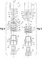
Figure 1 is an exploded perspective view of an embodiment of the adaptor of the invention,Figures 2A and 2B are perspective views of the inner ring of the adaptor ofFigure 1 ,Figures 3A and 3B are respectively a cross section view and a perspective view of the compressing means of the adaptor ofFigure 1 ,Figure 4 is a cross section view of a drug delivery device and adaptor of the invention, before the adaptor ofFigure 1 is mounted onto the distal tip of the drug delivery device,Figure 5 is a cross sectional view of the drug delivery device and adaptor ofFigure 4 , after engagement of the inner ring on the distal tip,Figure 6 is a cross section view of the drug delivery device and adaptor ofFigure 4 , when the adaptor is mounted on the distal tip,Figure 7 is a cross section view of the drug delivery device and adaptor ofFigure 4 , with a cap closing the distal tip of the drug delivery device.- With reference to
Figures 1-3B , is shown anadaptor 10 of the invention, comprising a first component, aninner ring 20, and a separate second component, anouter ring 30. Theadaptor 10 is intended to be mounted on adrug delivery device 1 comprising abarrel 5 and provided at its distal end with a distal tip 2 (seeFigure 4 ) in order to allow connection of a connector (not shown) to thedrug delivery device 1 via theadaptor 10. - The connector intended to be connected to the
drug delivery device 1 thanks to theadaptor 10 of the invention may be any device capable of being connected to theadaptor 10, either for allowing the transfer of a product from thedrug delivery device 1 to another medical device, such as a needle hub, a pocket drip, a vial, an IV (Intra Venous) line, an IM (Intra Muscular) line, or on the contrary for safely closing the filleddrug delivery device 1 before its use and for preventing any contamination, like for example aclosure cap 40 in the storage position of the drug delivery device (as will be shown onFigures 4-7 ). In the example shown, the connector is intended to be provided with a connecting means or connector connection member, such as a thread, capable of cooperating with a corresponding connecting means or connection member, for example thread 34 (seeFigure 3A ), located on theadaptor 10, as will be explained below. - With reference to
Figures 1-3B , the first component orinner ring 20 comprises acircular wall 21 provided at its distal end with an annularouter rim 22 having a distally taperedouter face 22a. Thecircular wall 21 is provided with alongitudinal cut 23 along a portion of its circumference, said portion of circumference separating the two longitudinal edges (23a, 23b) of thelongitudinal cut 23, and thereby defining an empty space between these two longitudinal edges (23a, 23b) when no pressure is exerted on saidcircular wall 21. Thelongitudinal cut 23 extends along the whole height of thecircular wall 21. The presence of thelongitudinal cut 23 defining said empty space confers to thecircular wall 21, and therefore to theinner ring 20, a capacity for radial expansion and a capacity for radial compression. OnFigure 2A , thecircular wall 21 is shown in a rest position. Anyway, thecircular wall 21 is deformable under a pressure exerted radially outwardly on itsinner face 21c, in which case the inner diameter of thecircular wall 21 increases under the deformation caused, the two longitudinal edges (23a, 23b) of thelongitudinal cut 23 moving away from each other. In addition, thecircular wall 21 is deformable under a pressure exerted radially inwardly on itsouter face 21d, in which case the inner diameter of thecircular wall 21 decreases under the deformation caused. In particular, the portion of the circumference along which thecircular wall 21 is cut is wide enough, for example at least 2 mm wide, so that the inner diameter of thecircular wall 21 is reduced when thecircular wall 21 is radially compressed, for example up until the two longitudinal edges (23a, 23b) of thecut 23 contact each other. Due to the presence of thelongitudinal cut 23 defining an empty space along the circumference of thecircular wall 21, the two longitudinal edges (23a, 23b) do not come in contact with each other when the circular wall is in its rest position. On the contrary, these two longitudinal edges (23a, 23b) may come in contact with each other when a pressure is exerted radially inwardly on thecircular wall 21. The portion of circumference defining the empty space between the two longitudinal edges (23a, 23b) of thelongitudinal cut 23 may be about 2 mm wide in order to provide enough elasticity to thecircular wall 21 so that saidcircular wall 21 is capable of being alternately radially compressed or radially expanded. Thecircular wall 21 therefore defines acentral hole 24 capable of outwardly radially expanding, and of inwardly radially shrinking depending on the nature of the pressure exerted on thecircular wall 21, saidcentral hole 24 being shaped and dimensioned in order to allow the engagement of theinner ring 20 on the distal tip 2 (seeFigure 5 ) of thedrug delivery device 1. The first component orinner ring 20 is transitionable between a first position in which the first component orinner ring 20 is releasably engaged with thedrug delivery device 1 and a second position in which theadaptor 10 is locked to thedrug delivery device 1. - On the example shown, the
circular wall 21 further comprises a plurality of circumferentially distributedproximal tabs 21a, separated from each other by a plurality ofspaces 21b, and linked together by the annularouter rim 22. On the example shown, thecircular wall 21 comprises five suchproximal tabs 21a. In examples not shown, thecircular wall 21 may comprise less or more of theseproximal tabs 21a, such as two, three, four, six or more. Theinner face 21c of theseproximal tabs 21a is intended to surround the outer surface of thedistal tip 2 when theinner ring 20 is engaged thereon (seeFigure 5 ). - On
Figures 1-3B , thecircular wall 21 is in a rest position, in other words it is in a neither expanded nor compressed state, as no pressure is exerted on itsinner face 21c or on itsouter face 21d. - With reference to
Figures 1-3B , the second component orouter ring 30 comprises acircular wall 31 provided at its proximal end with an innerradial rim 32. The innerradial rim 32 of theouter ring 30 defines acentral hole 33. The innerradial rim 32 is shaped and dimensioned so as to be capable of overcoming the distally taperedouter face 22a of the annularouter rim 22 of theinner ring 20. Additionally, the innerradial rim 32 is also capable of exerting a centripetal pressure on theouter face 21d of thecircular wall 21 when theinner ring 20 is engaged on thedistal tip 2, as shown onFigures 6 and 7 . In particular, when theouter ring 30 is approached towards theinner ring 20 in the proximal direction during the mounting step, the innerradial rim 32 overcomes the distally taperedouter face 22a of the annularouter rim 22 and becomes engaged on theouter face 21d of thecircular wall 21, thereby performing a snap-fitting connection between theouter ring 30 and theinner ring 20, as shown onFigures 6 and 7 . In this manner, the second component orouter ring 30 is engageable with the first component orinner ring 20 to transition the first component orinner ring 20 to the second position in which theadaptor 10 is locked to thedrug delivery device 1. - As shown on
Figures 1 and 3A , a connection member, athread 34, is provided on the inner face of thecircular wall 31 of theouter ring 30. As it will appear from the following description, thisthread 34 forms a connection member or connecting means for connecting theadaptor 10 to a connector (not shown) at the time of use of thedrug delivery device 1, for example to a cap in a storage position of the prefilleddrug delivery device 1. - In an embodiment not shown, the connecting means can be a groove provided on the outer face of the circular wall of the inner ring, in which a connector may be clipped. In other embodiments, the connection member or
thread 34 may comprise other connection mechanisms for connecting a connector to thedrug delivery device 1 via theadaptor 10. In one embodiment, the connector is connectable to the connection member orthread 34 of theadaptor 10 with the first component orinner ring 20 in the second position. - The
inner ring 20 and theouter ring 30 may be made of a material selected from acrylonitrile butadiene styrene (ABS), polycarbonate (PC), polyoxymethylene (POM), polystyrene (PS), polybutylene terephthalate (PBT), polypropylene (PP), polyethylene (PE), polyamide (PA), thermoplastic elastomer (TPE) and their combinations. - Anyway, as it will appear from the description below, as the
outer ring 30, and in particular its innerradial rim 32, is intended to compress inwardly radially theproximal tabs 21a of thecircular wall 21 of theinner ring 20 when theadaptor 10 is mounted on the distal tip 2 (seeFigure 7 ), in order to prevent any axial or rotational movement of theadaptor 10 with respect to saiddistal tip 2, the innerradial rim 32 is preferably made from a material more rigid than the material forming theproximal tabs 21a of thecircular wall 21 of theinner ring 20. - For example, in embodiments, the
outer ring 30, and in particular the innerradial rim 32, is made of polyamide and theproximal tabs 21a are made of polyethylene. - In other embodiments, the
outer ring 30, and in particular the innerradial rim 32, may be made of polybutylene terephthalate and theproximal tabs 21a may be made of thermoplastic elastomer. - As it will appear in the description later, the
adaptor 10 is intended to be engaged on the distal tip of a drug delivery device in a two-step process (seeFigures 5 and6 ), in which theinner ring 20 is first engaged onto thedistal tip 2 in a releasable way, and theouter ring 30 is then snap-fitted onto theinner ring 20 so as to axially lock it in translation with respect to thedistal tip 2. The mounting of theadaptor 10 on thedistal tip 2 of adrug delivery device 1 will now be described with reference toFigures 4-7 . - With reference to
Figure 4 is shown adrug delivery device 1 provided with adistal tip 2, and theadaptor 10, in a position where none of theinner ring 20 and theouter ring 30 is yet engaged on thedistal tip 2. - The
drug delivery device 1 and theadaptor 10 are aligned and have a common longitudinal axis A. The outer surface of thedistal tip 2 is conical and distally tapered. Thedistal tip 2 defines anaxial passageway 3 for the transfer of a product (not shown) contained or intended to be contained in thedrug delivery device 1. Theaxial passageway 3 is open at itsdistal end 3a. In the example shown, thedistal tip 2 is further provided with a proximalannular groove 4. The proximalannular groove 4 is defined between adistal step 4a and aproximal shoulder 4b formed by the distal part of thebarrel 5 of thedrug delivery device 1. For example, the outer diameter of thedistal tip 2 at the location of the proximalannular groove 4 is smaller than the outer diameter of thedistal tip 2 at its most distal part. - In embodiments not shown, the outer surface of the
distal tip 2 may be free of any annular groove, or alternatively may be provided with an annular ridge. - The
distal tip 2 may be made of plastic or glass material. In embodiments, thedistal tip 2 is made of glass material. In another embodiment, thedistal tip 2, as well as the drug delivery device, is made of plastic material selected from crystal clear polymer (CCP), acrylonitrile butadiene styrene (ABS), polycarbonate (PC), polystyrene (PS), polypropylene (PP), polyethylene (PE), polyamide (PA) and their combinations. - On
Figure 4 is also shown acap 40 comprising arubber plug 41 and arigid sleeve 42 capable of receiving therubber plug 41. As shown in the following description, thecap 40 is intended to close the opendistal end 3a of thepassageway 3 of thedistal tip 2 of thedrug delivery device 1, when thedrug delivery device 1 is not in use but serves as a storage container of the medical product. As shown in the following description, thecap 40 is not part of the adaptor of the invention, and is intended to be removed at the time of use of the drug delivery device 1 : indeed, when a user wishes to transfer the product from thedrug delivery device 1 into another medical device (such as an infusion line, another syringe, etc...), thecap 40 is removed and replaced by a connector (not shown) allowing the transfer of the medical product from thedrug delivery device 1 to said other medical device. Figures 4-7 show the mounting of theadaptor 10 on thedistal tip 2 of thedrug delivery device 1 so as to obtain onFigure 7 thedrug delivery device 1 in a storage position. As a consequence, thecap 40 is mounted on thedrug delivery device 1 so as to close thedistal end 3a of thedistal tip 3, thethread 34 thereby forming a connecting means or connection member for connecting thecap 40 to theouter ring 30, by cooperating with a correspondingouter thread 43 provided on the outer wall of therigid sleeve 42.- As already mentioned above, the
cap 40 is not part of theadaptor 10 of the invention and is intended to be replaced with a connector (not shown) provided with a thread capable of cooperating with thethread 34 of theouter ring 30, in view of transferring product from thedrug delivery device 1 to another medical device. - On
Figure 4 , theinner ring 20 of theadaptor 10 is not engaged yet on thedistal tip 2, and thecircular wall 21 is not submitted to any strain and is therefore in a rest position. - In a first step, the user engages the
inner ring 20 onto thedistal tip 2. This step is easy to perform thanks to the distally tapered shape of the outer surface of thedistal tip 2 and also thanks to the capability of thecircular wall 21 of theinner ring 20 to expand outwardly radially. In particular, the presence of thelongitudinal cut 23 of thecircular wall 21 facilitates the mounting of theinner ring 20 onto thedistal tip 2. On the example shown, theinner ring 20 is engaged on thedistal tip 2 beyonddistal step 4a of proximalannular groove 4. With reference toFigure 5 , theinner ring 20 is engaged on thedistal tip 2 until theinner face 21c of thecircular wall 21 faces and is in contact with theannular groove 4 of thedistal tip 2. - In embodiments where the
distal tip 2 is free of any annular groove, theinner ring 20 may be engaged on saiddistal tip 2 until the proximal end of the inner ring comes close to the shoulder formed by the distal part of thebarrel 5 of thedrug delivery device 1. - When the
inner ring 20 is engaged on thedistal tip 2 and theouter ring 30 is not yet snap-fitted thereon, theproximal tabs 21a of thecircular wall 21 may exert a slight radial inward force on thedistal tip 2, regardless form the fact that saiddistal tip 2 is provided with an annular groove or not. Alternatively, theseproximal tabs 21a may exert no inward radial force onto thedistal tip 2. At this stage, theinner ring 20 is engaged on thedistal tip 2 in a releasable way, and the potential radial inward force exerted by thecircular wall 21 on thedistal tip 2 does not limit the axial movement of theinner ring 20 with respect to thedistal tip 2. Theinner ring 20 may still be translated with respect to thedistal tip 2. - In the example shown, where the
distal tip 2 is provided with anannular groove 4 forming adistal abutment 4a for theinner ring 20, theproximal tabs 21a of thecircular wall 21 do not exert any radial inward force on the outer face of theannular groove 4 if the outer diameter of the proximalannular groove 4 is less than the inner diameter of thecircular wall 21 in a rest position. - Then, the user approaches the
outer ring 30 to the distal end of thedistal tip 2, engages it thereon and towards theinner ring 20 already in place on thedistal tip 2. When the user moves theouter ring 30 in the proximal direction, the innerradial rim 32 comes in contact with the distally taperedouter face 22a of the annularouter rim 22 of theinner ring 20. Thanks to the distally taperedouter face 22a of the annularouter rim 22 and to the inherent flexibility of the material forming theouter ring 30, the innerradial rim 32 overcomes the annularouter rim 22 and gets engaged on theouter face 21d of thecircular wall 21. Theouter ring 30 is therefore snap-fitted into theinner ring 20. - In embodiments where the
distal tip 2 is provided with anannular groove 4 and where the outer diameter of the proximalannular groove 4 is less than the inner diameter of thecircular wall 21 in a rest position, the innerradial rim 32 may even cause the annularouter rim 22 to deflect radially inwardly thanks to the capability of thecircular wall 21 to be compressed under a pressure exerted on itsouter face 21d radially inwardly. - With reference to
Figure 6 , in this position, theouter ring 30, via its innerradial rim 32, exerts a radial inwardly pressure on theproximal tabs 21a, in other words on theouter face 21d of thecircular wall 21, thereby compressing saidcircular wall 21. Theouter ring 30, via its innerradial rim 32, acts as a compressing means or compression component exerting a centripetal pressure on thecircular wall 21 so as to lock theinner ring 20 in translation with respect to thedistal tip 2. The radial inward force exerted on thedistal tip 2 therefore limits and prevents the axial movement of theinner ring 20, and therefore of theadaptor 10, with respect to saiddistal tip 2. - In addition, as shown on
Figures 6 and 7 , the innerradial rim 32 is in distal abutment on the annularouter rim 22. The innerradial rim 32 and the annularouter rim 22 therefore forms unreleasable snap-fitting means or engagement of theouter ring 30 into theinner ring 20. - Additionnally, in an embodiment not shown, some locking means or locking component may be formed on the outer surface of the distal tip, such locking means being preferably aligned on the longitudinal axis of the drug delivery device. These locking means may have the form of ribs capable of locking the adaptor firmly in rotation thanks to a mechanical abutment with the
proximal tabs 21a. These ribs may fit closely within the space existing between two adjacent proximal tabs in order to prevent any rotational movement of the adaptor with respect to the distal tip. Preferably at least two locking means would be required, but the number of the locking means and their distribution on the surface of the distal tip may depend on the number of free spaces existing between two adjacentproximal tabs 21a. - As a consequence, the
adaptor 10 is now firmly attached to thedistal tip 2, and it may not be disconnected from said distal tip, even if a user tries to pull it out in a direction or the other. The presence of the proximalannular groove 4 on thedistal tip 2 increases the fastening resistance of theadaptor 10 onto thedistal tip 2 if a user tries to pull it in the distal direction. - As shown in
Figure 7 , thepassageway 3 of thedistal tip 2 may be closed by screwing acap 40 onthread 34 of theouter ring 30 for storage purposes. - In embodiments, the
adaptor 10 may be provided with thecap 40 already screwed in theouter ring 30, before any mounting step of theadaptor 10 onto the distal tip of the drug delivery device. Theadaptor 10 may then be provided with a tamper evidence component or tamper evidence means of the removal of thecap 40. For example, a tearable label 50 as shown onFigure 7 may be stuck bridging the distal part of theouter ring 30 and the proximal part of thecap 40 so as to constitute tamper evidence means of the removal of thecap 40 from theadaptor 10. - For using the
drug delivery device 1, the user only needs to remove first the tearable label 50 if present, and then thecap 40 by unscrewing it from theouter ring 30. This step is easy to complete thanks to the secured fixation of theadaptor 10 onto thedistal tip 2. In particular, the user knows that the removal of thecap 40 can be done safely and may not cause theadaptor 10 to be separated from thedistal tip 2. Once thecap 40 is removed, the user may then screw on thread 34 a corresponding outer thread provided on a connector (not shown) in order to proceed to the transfer of the product contained in the drug delivery device to another medical device via the connector. - Again, because of the optimized fixation of the
adaptor 10 on thedistal tip 2, the connection of the connector to theadaptor 10, and therefore to thedistal tip 2 is facilitated. - The adaptor of the invention allows the reliable connection of a connector on the distal tip of a drug delivery device. The risks that the adaptor of the invention be displaced and eventually misplaced on the distal tip of the drug delivery device and that the connector be wrongly connected are greatly limited.
Claims (14)
- Adaptor (10) intended to be mounted on a distal tip (2) of a drug delivery device (1), said distal tip defining an axial passageway (3) for the transfer of a product contained in said drug delivery device, said adaptor having a longitudinal axis A aligned on said axial passageway, the adaptor comprising connecting means (34) for connecting said adaptor to a connector,characterized in that said adaptor further comprises :- an inner ring (20) releasably engageable on said distal tip,- compressing means (30, 32), separate from said inner ring and intended to be unreleasably snap-fitted onto said inner ring engaged on said distal tip by proximal movement of said compressing means with respect to said inner ring, said compressing means being capable of exerting a centripetal pressure on said inner ring so as to prevent axial movement of said inner ring with respect to said distal tip,wherein said inner ring comprises a circular wall (21) capable of being outwardly radially expanded under a pressure exerted radially outwardly on an inner face (21c) of said circular wall, and capable of being inwardly radially compressed under a pressure exerted radially inwardly on an outer face (21d) of said circular wall, said compressing means comprise an outer ring (30) capable of receiving at least partly said inner ring, said outer ring comprising an inner radial rim (32) capable of exerting a centripetal pressure on said outer face (21d) of said circular wall (21) when said compressing means is snap-fitted onto said inner ring,
wherein said circular wall (21) is provided with a longitudinal cut (23) along a portion of its circumference, said longitudinal cut extending from a proximal end to a distal end of said circular wall (21). - Adaptor (10) according to claim 1, wherein said portion of circumference is wide enough for defining an empty space between two longitudinal edges of said longitudinal cut (23), when no pressure is exerted on said circular wall (21).
- Adaptor (10) according to claim 2, wherein said portion of circumference is at least 2 mm wide.
- Adaptor (10) according to any one of claims 1 to 3, wherein said circular wall (21) is provided with a distal annular outer rim (22) capable of cooperating with said inner radial rim (32) for unreleasably snap-fitting said compressing means onto said inner ring.
- Adaptor (10) according to any one of claims 1 to 4, wherein said connecting means (34) are located on the compressing means.
- Adaptor (10) according to any one of claims 1-5, wherein said connecting means comprises a thread (34) provided on an inner wall of said outer ring (30).
- Drug delivery device (1) comprising a distal tip (2) defining an axial passageway (3) for the transfer of a product contained in said drug delivery device,characterized in that it further comprises at least one adaptor (10) according to any one of claims 1 to 6.
- Drug delivery device (1) according to the preceding claim, wherein the distal tip (2) is made of glass.
- Drug delivery device (1) according to claim 7 or 8, wherein the distal tip (2) is conical and distally tapered.
- Drug delivery device (1) according to any one of claims 7 to 9, wherein the distal tip (2) is provided with an annular groove (4) capable of receiving said inner ring when said inner ring is engaged on said distal tip.
- Method for mounting an adaptor (10) according to claims 1 to 6 on the distal tip (2) of a drug delivery device (1) according to claims 7 to 10, comprising at least the following steps:- slidingly engaging the inner ring (20) onto the distal tip,- snap-fitting the compressing means (30) onto the inner ring by proximal movement of said compressing means with respect to said inner ring.
- Method according to claims 10 and 11, wherein the inner ring (20) is slidingly engaged on the distal tip until it is received into said annular groove (4).
- Assembly comprising an adaptor (10) according to any one of claims 1-6 and a connector (40) connected to said adaptor.
- Assembly according to claim 13, further comprising tamper evidence means of the removal of the connector from the adaptor.
Priority Applications (1)
| Application Number | Priority Date | Filing Date | Title |
|---|---|---|---|
| EP14737278.3AEP3021933B1 (en) | 2013-07-15 | 2014-07-11 | Adaptor for a drug delivery device and method for mounting said adaptor thereon |
Applications Claiming Priority (3)
| Application Number | Priority Date | Filing Date | Title |
|---|---|---|---|
| EP13306009.5AEP2826519A1 (en) | 2013-07-15 | 2013-07-15 | Adaptor for a drug delivery device and method for mounting said adaptor thereon |
| EP14737278.3AEP3021933B1 (en) | 2013-07-15 | 2014-07-11 | Adaptor for a drug delivery device and method for mounting said adaptor thereon |
| PCT/EP2014/064947WO2015007650A1 (en) | 2013-07-15 | 2014-07-11 | Adaptor for a drug delivery device and method for mounting said adaptor thereon |
Publications (2)
| Publication Number | Publication Date |
|---|---|
| EP3021933A1 EP3021933A1 (en) | 2016-05-25 |
| EP3021933B1true EP3021933B1 (en) | 2018-01-17 |
Family
ID=48875631
Family Applications (2)
| Application Number | Title | Priority Date | Filing Date |
|---|---|---|---|
| EP13306009.5AWithdrawnEP2826519A1 (en) | 2013-07-15 | 2013-07-15 | Adaptor for a drug delivery device and method for mounting said adaptor thereon |
| EP14737278.3AActiveEP3021933B1 (en) | 2013-07-15 | 2014-07-11 | Adaptor for a drug delivery device and method for mounting said adaptor thereon |
Family Applications Before (1)
| Application Number | Title | Priority Date | Filing Date |
|---|---|---|---|
| EP13306009.5AWithdrawnEP2826519A1 (en) | 2013-07-15 | 2013-07-15 | Adaptor for a drug delivery device and method for mounting said adaptor thereon |
Country Status (10)
| Country | Link |
|---|---|
| US (1) | US10258540B2 (en) |
| EP (2) | EP2826519A1 (en) |
| JP (2) | JP6693871B2 (en) |
| KR (1) | KR102265144B1 (en) |
| CN (2) | CN204017006U (en) |
| ES (1) | ES2661726T3 (en) |
| HU (1) | HUE037240T2 (en) |
| RU (1) | RU2640946C2 (en) |
| TR (1) | TR201802983T4 (en) |
| WO (1) | WO2015007650A1 (en) |
Families Citing this family (21)
| Publication number | Priority date | Publication date | Assignee | Title |
|---|---|---|---|---|
| EP3020446A4 (en)* | 2013-07-09 | 2017-05-03 | Nipro Corporation | Connector for fluid, and syringe |
| EP2826519A1 (en)* | 2013-07-15 | 2015-01-21 | Becton Dickinson France | Adaptor for a drug delivery device and method for mounting said adaptor thereon |
| RU2713371C2 (en)* | 2015-06-12 | 2020-02-04 | Бектон Дикинсон Франс | Adapter for drug delivery device and drug delivery device |
| US10328250B2 (en) | 2015-07-02 | 2019-06-25 | Covellus Llc | Medical device adapter |
| US11660439B2 (en) | 2015-07-02 | 2023-05-30 | Covellus Llc | Modular medical device system |
| US10814120B2 (en) | 2015-07-02 | 2020-10-27 | Covellus Llc | Modular medical device catheter system |
| US10912922B2 (en) | 2015-07-02 | 2021-02-09 | Covellus Llc | Modular medical device catheter system |
| CN105233385B (en)* | 2015-10-16 | 2017-12-08 | 山东省千佛山医院 | A trachea tube sealing device |
| WO2017100621A1 (en) | 2015-12-11 | 2017-06-15 | Nxstage Medical, Inc. | Fluid line connector devices methods and systems |
| US10485483B1 (en)* | 2016-10-17 | 2019-11-26 | Srs Medical Systems, Llc | Diagnostic drainage catheter assembly and methods |
| WO2019053112A1 (en)* | 2017-09-14 | 2019-03-21 | Becton Dickinson France | Safety assembly |
| MX2020004082A (en)* | 2017-10-06 | 2020-07-29 | Nordson Corp | Tamper-evident closure assembly. |
| ES2974449T3 (en)* | 2018-05-17 | 2024-06-27 | Becton Dickinson France | Connector for connecting a medical injection device to a container |
| KR102182278B1 (en)* | 2018-10-24 | 2020-11-24 | (주)풍림파마텍 | Syringe cap for preventing reuse |
| CN114007669A (en)* | 2019-06-28 | 2022-02-01 | 贝克顿迪金森法国公司 | Medical container and drug delivery device comprising the same |
| EP3868437A1 (en)* | 2020-02-18 | 2021-08-25 | Becton Dickinson France | An adaptor for mounting onto a medical container, a medical container comprising said adaptor, and a method for manufacturing said adaptor |
| EP3900764B1 (en) | 2020-04-21 | 2025-07-09 | Becton Dickinson France | A medical container, an adaptor for mounting onto said medical container, and a drug delivery device comprising said medical container |
| MX2022013481A (en) | 2020-11-02 | 2022-11-16 | Becton Dickinson Co | RADIO FREQUENCY IDENTIFICATION (RFID) INLAYS FOR USE WITH MEDICAL INJECTION DEVICES. |
| RU203827U1 (en)* | 2020-12-23 | 2021-04-22 | Общество С Ограниченной Ответственностью Химикофармацевтический Концерн "Медполимер" | Medical vial stopper |
| EP4230242A1 (en)* | 2022-02-21 | 2023-08-23 | Becton Dickinson France | Adaptor for connecting a connector to a distal tip of a medical container, tip cap assembly and drug delivery device for engaging said adaptor, and method for manufacturing said adaptor |
| EP4275720A1 (en)* | 2022-05-09 | 2023-11-15 | Becton, Dickinson and Company | Castellated syringe product label |
Family Cites Families (41)
| Publication number | Priority date | Publication date | Assignee | Title |
|---|---|---|---|---|
| JPS5735Y2 (en)* | 1977-01-06 | 1982-01-05 | ||
| US4895570A (en) | 1987-06-05 | 1990-01-23 | Abbott Laboratories | Locking port shroud for peritoneal dialysis tubing connector |
| US5833275A (en) | 1994-11-29 | 1998-11-10 | Corpak, Inc. | Locking medical connector |
| US5624402A (en)* | 1994-12-12 | 1997-04-29 | Becton, Dickinson And Company | Syringe tip cap |
| US6196998B1 (en) | 1994-12-12 | 2001-03-06 | Becton Dickinson And Company | Syringe and tip cap assembly |
| DE19547431A1 (en) | 1995-12-05 | 1997-06-12 | Schering Ag | Closure system for a sterile syringe |
| WO1999044661A1 (en)* | 1998-03-06 | 1999-09-10 | Paiva Marques Jose Luiz De | Locking and blocking system for descardable or disposable syringe |
| DE19909824A1 (en) | 1999-03-05 | 2000-09-07 | Vetter & Co Apotheker | Syringe for medical purposes and assembly method |
| FR2809316B1 (en)* | 2000-05-26 | 2002-07-26 | Becton Dickinson France | SEALED CONNECTION DEVICE FOR MEDICAL USE, OF THE "LUER-LOCK" TYPE, AND SYRINGE INCORPORATING SUCH A DEVICE |
| US6908459B2 (en)* | 2001-12-07 | 2005-06-21 | Becton, Dickinson And Company | Needleless luer access connector |
| JP2004329504A (en)* | 2003-05-06 | 2004-11-25 | Kooki Engineering:Kk | Cylinder of syringe, method of manufacturing the same, and syringe needle retaining cylinder part for the cylinder |
| US7377909B2 (en)* | 2003-06-19 | 2008-05-27 | Claude L Rickerd | Connection assembly for use with splittable sheath |
| EP1600190B1 (en) | 2004-05-29 | 2007-08-29 | Gerresheimer Bünde GmbH | Syringe cap and method of producing a syringe cap |
| US7497484B2 (en)* | 2004-08-11 | 2009-03-03 | Smiths Medical Asd, Inc. | Medical coupling system |
| WO2006087763A1 (en) | 2005-02-15 | 2006-08-24 | Kabushiki Kaisha Top | Connector |
| DE102005052545A1 (en) | 2005-11-02 | 2007-05-03 | Schering Ag | Closure for medical syringe, has syringe cylinder and connected syringe neck at distal end whereby syringe neck has fixable adapter in which screw cap is fixable |
| JP4775038B2 (en)* | 2006-03-02 | 2011-09-21 | ニプロ株式会社 | Medical connection holding member, medical fixing auxiliary component, and medical connection member set |
| SG174097A1 (en)* | 2007-06-08 | 2011-09-29 | Jms Co Ltd | Male connector |
| JP5325101B2 (en) | 2007-06-11 | 2013-10-23 | 株式会社根本杏林堂 | Nozzle adapter for chemical syringe |
| FR2931681B1 (en) | 2008-05-30 | 2011-11-25 | Becton Dickinson France | SYRINGE WITH UNIVERSAL TIP |
| PL2138202T3 (en)* | 2008-06-23 | 2010-09-30 | Logica Medizintechnik Gmbh | Connecting part for connecting with a standardised luer lock connection |
| US8062280B2 (en)* | 2008-08-19 | 2011-11-22 | Baxter Healthcare S.A. | Port assembly for use with needleless connector |
| DE202008014483U1 (en) | 2008-10-31 | 2010-03-18 | Gebrüder Beul GmbH & Co KG | Connectors |
| DE102009007250A1 (en)* | 2009-01-26 | 2010-07-29 | Arzneimittel Gmbh Apotheker Vetter & Co. Ravensburg | syringe |
| JP5514304B2 (en) | 2009-06-03 | 2014-06-04 | ベクトン ディキンソン フランス | Improved luer lock adapter |
| WO2010150042A1 (en)* | 2009-06-24 | 2010-12-29 | Becton Dickinson France | Improved luer connector |
| JP2011244913A (en)* | 2010-05-25 | 2011-12-08 | Fuji Seal International Inc | Adapter, and spouted pouch equipped with the same |
| JP5552678B2 (en)* | 2010-09-28 | 2014-07-16 | 株式会社フジシール | Adapter and pouch with spout equipped with adapter |
| CN101966127B (en)* | 2010-10-18 | 2013-06-05 | 有益安生化科技股份有限公司 | Safety syringe |
| HUE028831T2 (en)* | 2010-12-16 | 2017-02-28 | Becton Dickinson France | Adapter and drug delivery device |
| RU2013144348A (en) | 2011-03-03 | 2015-04-10 | Феттер Фарма-Фертигунг Гмбх Унд Ко. Кг | COVER AND METHOD FOR PRODUCING COVER |
| EP2510964A1 (en)* | 2011-04-11 | 2012-10-17 | Becton Dickinson France | Needle assembly and injection device with foldable needle protecting means |
| EP2545957A1 (en) | 2011-07-15 | 2013-01-16 | Becton Dickinson France | Drug delivery device and adaptor |
| JP5962948B2 (en)* | 2011-11-28 | 2016-08-03 | 株式会社ジェイ・エム・エス | Medical syringe |
| JP5999404B2 (en)* | 2011-11-28 | 2016-09-28 | 株式会社ジェイ・エム・エス | Medical syringe |
| DE102011089045A1 (en)* | 2011-12-19 | 2013-06-20 | Schott Ag | Borosilicate glass syringe with a surface roughness increasing cone coating |
| EP2719420A1 (en) | 2012-10-12 | 2014-04-16 | Becton Dickinson France | Adaptor for a drug delivery device and method for mounting said adaptor thereon |
| DE102012022008A1 (en) | 2012-11-09 | 2014-05-15 | Vetter Pharma-Fertigung GmbH & Co. KG | syringe closure |
| DE102013009619A1 (en) | 2012-12-07 | 2014-06-12 | Schott Schweiz Ag | Closure, in particular syringe closure for the sealing closing of a distal opening of a syringe body |
| EP3020446A4 (en) | 2013-07-09 | 2017-05-03 | Nipro Corporation | Connector for fluid, and syringe |
| EP2826519A1 (en)* | 2013-07-15 | 2015-01-21 | Becton Dickinson France | Adaptor for a drug delivery device and method for mounting said adaptor thereon |
- 2013
- 2013-07-15EPEP13306009.5Apatent/EP2826519A1/ennot_activeWithdrawn
- 2014
- 2014-07-11JPJP2016526551Apatent/JP6693871B2/enactiveActive
- 2014-07-11USUS14/905,063patent/US10258540B2/enactiveActive
- 2014-07-11RURU2016104177Apatent/RU2640946C2/enactive
- 2014-07-11KRKR1020167000724Apatent/KR102265144B1/enactiveActive
- 2014-07-11WOPCT/EP2014/064947patent/WO2015007650A1/enactiveApplication Filing
- 2014-07-11HUHUE14737278Apatent/HUE037240T2/enunknown
- 2014-07-11TRTR2018/02983Tpatent/TR201802983T4/enunknown
- 2014-07-11ESES14737278.3Tpatent/ES2661726T3/enactiveActive
- 2014-07-11EPEP14737278.3Apatent/EP3021933B1/enactiveActive
- 2014-07-15CNCN201420505132.5Upatent/CN204017006U/ennot_activeWithdrawn - After Issue
- 2014-07-15CNCN201410445676.1Apatent/CN104288855B/enactiveActive
- 2019
- 2019-02-22JPJP2019031001Apatent/JP6873173B2/enactiveActive
Also Published As
| Publication number | Publication date |
|---|---|
| EP3021933A1 (en) | 2016-05-25 |
| HUE037240T2 (en) | 2018-08-28 |
| WO2015007650A1 (en) | 2015-01-22 |
| CN204017006U (en) | 2014-12-17 |
| EP2826519A1 (en) | 2015-01-21 |
| JP2019069393A (en) | 2019-05-09 |
| JP6693871B2 (en) | 2020-05-13 |
| JP6873173B2 (en) | 2021-05-19 |
| CN104288855B (en) | 2020-01-17 |
| US20160143811A1 (en) | 2016-05-26 |
| KR102265144B1 (en) | 2021-06-15 |
| TR201802983T4 (en) | 2018-03-21 |
| RU2640946C2 (en) | 2018-01-12 |
| JP2016525395A (en) | 2016-08-25 |
| CN104288855A (en) | 2015-01-21 |
| ES2661726T3 (en) | 2018-04-03 |
| US10258540B2 (en) | 2019-04-16 |
| RU2016104177A (en) | 2017-08-18 |
| KR20160030510A (en) | 2016-03-18 |
Similar Documents
| Publication | Publication Date | Title |
|---|---|---|
| EP3021933B1 (en) | Adaptor for a drug delivery device and method for mounting said adaptor thereon | |
| EP2906287B1 (en) | Adaptor for a drug delivery device and method for mounting said adaptor thereon | |
| US6196998B1 (en) | Syringe and tip cap assembly | |
| CN107596504B (en) | Tip cap assembly, drug injection system and method of manufacturing the same | |
| US20230055325A1 (en) | Adaptor for Connecting a Drug Delivery Device to a Connector | |
| EP4212142B1 (en) | Vial adaptor providing audible feedback and connector assembly for medical injection device including vial adaptor | |
| EP4212143B1 (en) | Connector assembly for medical injection device | |
| EP4527434A1 (en) | Syringe needle shield with tamper evidence feature and consistent needle pull-out force | |
| WO2025080782A1 (en) | Syringe plunger rod with simplified stopper disconnection |
Legal Events
| Date | Code | Title | Description |
|---|---|---|---|
| PUAI | Public reference made under article 153(3) epc to a published international application that has entered the european phase | Free format text:ORIGINAL CODE: 0009012 | |
| 17P | Request for examination filed | Effective date:20160209 | |
| AK | Designated contracting states | Kind code of ref document:A1 Designated state(s):AL AT BE BG CH CY CZ DE DK EE ES FI FR GB GR HR HU IE IS IT LI LT LU LV MC MK MT NL NO PL PT RO RS SE SI SK SM TR | |
| AX | Request for extension of the european patent | Extension state:BA ME | |
| DAX | Request for extension of the european patent (deleted) | ||
| GRAP | Despatch of communication of intention to grant a patent | Free format text:ORIGINAL CODE: EPIDOSNIGR1 | |
| INTG | Intention to grant announced | Effective date:20170830 | |
| GRAS | Grant fee paid | Free format text:ORIGINAL CODE: EPIDOSNIGR3 | |
| GRAA | (expected) grant | Free format text:ORIGINAL CODE: 0009210 | |
| AK | Designated contracting states | Kind code of ref document:B1 Designated state(s):AL AT BE BG CH CY CZ DE DK EE ES FI FR GB GR HR HU IE IS IT LI LT LU LV MC MK MT NL NO PL PT RO RS SE SI SK SM TR | |
| REG | Reference to a national code | Ref country code:GB Ref legal event code:FG4D | |
| REG | Reference to a national code | Ref country code:CH Ref legal event code:EP | |
| REG | Reference to a national code | Ref country code:IE Ref legal event code:FG4D | |
| REG | Reference to a national code | Ref country code:AT Ref legal event code:REF Ref document number:964005 Country of ref document:AT Kind code of ref document:T Effective date:20180215 | |
| REG | Reference to a national code | Ref country code:DE Ref legal event code:R096 Ref document number:602014020065 Country of ref document:DE | |
| REG | Reference to a national code | Ref country code:CH Ref legal event code:NV Representative=s name:CABINET GERMAIN AND MAUREAU, CH | |
| REG | Reference to a national code | Ref country code:ES Ref legal event code:FG2A Ref document number:2661726 Country of ref document:ES Kind code of ref document:T3 Effective date:20180403 | |
| REG | Reference to a national code | Ref country code:NL Ref legal event code:MP Effective date:20180117 | |
| REG | Reference to a national code | Ref country code:LT Ref legal event code:MG4D | |
| REG | Reference to a national code | Ref country code:AT Ref legal event code:MK05 Ref document number:964005 Country of ref document:AT Kind code of ref document:T Effective date:20180117 | |
| REG | Reference to a national code | Ref country code:FR Ref legal event code:PLFP Year of fee payment:5 | |
| PG25 | Lapsed in a contracting state [announced via postgrant information from national office to epo] | Ref country code:NL Free format text:LAPSE BECAUSE OF FAILURE TO SUBMIT A TRANSLATION OF THE DESCRIPTION OR TO PAY THE FEE WITHIN THE PRESCRIBED TIME-LIMIT Effective date:20180117 | |
| PG25 | Lapsed in a contracting state [announced via postgrant information from national office to epo] | Ref country code:LT Free format text:LAPSE BECAUSE OF FAILURE TO SUBMIT A TRANSLATION OF THE DESCRIPTION OR TO PAY THE FEE WITHIN THE PRESCRIBED TIME-LIMIT Effective date:20180117 Ref country code:HR Free format text:LAPSE BECAUSE OF FAILURE TO SUBMIT A TRANSLATION OF THE DESCRIPTION OR TO PAY THE FEE WITHIN THE PRESCRIBED TIME-LIMIT Effective date:20180117 Ref country code:NO Free format text:LAPSE BECAUSE OF FAILURE TO SUBMIT A TRANSLATION OF THE DESCRIPTION OR TO PAY THE FEE WITHIN THE PRESCRIBED TIME-LIMIT Effective date:20180417 Ref country code:FI Free format text:LAPSE BECAUSE OF FAILURE TO SUBMIT A TRANSLATION OF THE DESCRIPTION OR TO PAY THE FEE WITHIN THE PRESCRIBED TIME-LIMIT Effective date:20180117 Ref country code:CY Free format text:LAPSE BECAUSE OF FAILURE TO SUBMIT A TRANSLATION OF THE DESCRIPTION OR TO PAY THE FEE WITHIN THE PRESCRIBED TIME-LIMIT Effective date:20180117 | |
| REG | Reference to a national code | Ref country code:HU Ref legal event code:AG4A Ref document number:E037240 Country of ref document:HU | |
| PG25 | Lapsed in a contracting state [announced via postgrant information from national office to epo] | Ref country code:IS Free format text:LAPSE BECAUSE OF FAILURE TO SUBMIT A TRANSLATION OF THE DESCRIPTION OR TO PAY THE FEE WITHIN THE PRESCRIBED TIME-LIMIT Effective date:20180517 Ref country code:SE Free format text:LAPSE BECAUSE OF FAILURE TO SUBMIT A TRANSLATION OF THE DESCRIPTION OR TO PAY THE FEE WITHIN THE PRESCRIBED TIME-LIMIT Effective date:20180117 Ref country code:LV Free format text:LAPSE BECAUSE OF FAILURE TO SUBMIT A TRANSLATION OF THE DESCRIPTION OR TO PAY THE FEE WITHIN THE PRESCRIBED TIME-LIMIT Effective date:20180117 Ref country code:PL Free format text:LAPSE BECAUSE OF FAILURE TO SUBMIT A TRANSLATION OF THE DESCRIPTION OR TO PAY THE FEE WITHIN THE PRESCRIBED TIME-LIMIT Effective date:20180117 Ref country code:GR Free format text:LAPSE BECAUSE OF FAILURE TO SUBMIT A TRANSLATION OF THE DESCRIPTION OR TO PAY THE FEE WITHIN THE PRESCRIBED TIME-LIMIT Effective date:20180418 Ref country code:BG Free format text:LAPSE BECAUSE OF FAILURE TO SUBMIT A TRANSLATION OF THE DESCRIPTION OR TO PAY THE FEE WITHIN THE PRESCRIBED TIME-LIMIT Effective date:20180417 Ref country code:RS Free format text:LAPSE BECAUSE OF FAILURE TO SUBMIT A TRANSLATION OF THE DESCRIPTION OR TO PAY THE FEE WITHIN THE PRESCRIBED TIME-LIMIT Effective date:20180117 Ref country code:AT Free format text:LAPSE BECAUSE OF FAILURE TO SUBMIT A TRANSLATION OF THE DESCRIPTION OR TO PAY THE FEE WITHIN THE PRESCRIBED TIME-LIMIT Effective date:20180117 | |
| REG | Reference to a national code | Ref country code:DE Ref legal event code:R097 Ref document number:602014020065 Country of ref document:DE | |
| PG25 | Lapsed in a contracting state [announced via postgrant information from national office to epo] | Ref country code:AL Free format text:LAPSE BECAUSE OF FAILURE TO SUBMIT A TRANSLATION OF THE DESCRIPTION OR TO PAY THE FEE WITHIN THE PRESCRIBED TIME-LIMIT Effective date:20180117 Ref country code:EE Free format text:LAPSE BECAUSE OF FAILURE TO SUBMIT A TRANSLATION OF THE DESCRIPTION OR TO PAY THE FEE WITHIN THE PRESCRIBED TIME-LIMIT Effective date:20180117 Ref country code:RO Free format text:LAPSE BECAUSE OF FAILURE TO SUBMIT A TRANSLATION OF THE DESCRIPTION OR TO PAY THE FEE WITHIN THE PRESCRIBED TIME-LIMIT Effective date:20180117 | |
| PLBE | No opposition filed within time limit | Free format text:ORIGINAL CODE: 0009261 | |
| STAA | Information on the status of an ep patent application or granted ep patent | Free format text:STATUS: NO OPPOSITION FILED WITHIN TIME LIMIT | |
| PG25 | Lapsed in a contracting state [announced via postgrant information from national office to epo] | Ref country code:SM Free format text:LAPSE BECAUSE OF FAILURE TO SUBMIT A TRANSLATION OF THE DESCRIPTION OR TO PAY THE FEE WITHIN THE PRESCRIBED TIME-LIMIT Effective date:20180117 Ref country code:CZ Free format text:LAPSE BECAUSE OF FAILURE TO SUBMIT A TRANSLATION OF THE DESCRIPTION OR TO PAY THE FEE WITHIN THE PRESCRIBED TIME-LIMIT Effective date:20180117 Ref country code:SK Free format text:LAPSE BECAUSE OF FAILURE TO SUBMIT A TRANSLATION OF THE DESCRIPTION OR TO PAY THE FEE WITHIN THE PRESCRIBED TIME-LIMIT Effective date:20180117 Ref country code:DK Free format text:LAPSE BECAUSE OF FAILURE TO SUBMIT A TRANSLATION OF THE DESCRIPTION OR TO PAY THE FEE WITHIN THE PRESCRIBED TIME-LIMIT Effective date:20180117 | |
| 26N | No opposition filed | Effective date:20181018 | |
| PG25 | Lapsed in a contracting state [announced via postgrant information from national office to epo] | Ref country code:SI Free format text:LAPSE BECAUSE OF FAILURE TO SUBMIT A TRANSLATION OF THE DESCRIPTION OR TO PAY THE FEE WITHIN THE PRESCRIBED TIME-LIMIT Effective date:20180117 | |
| PG25 | Lapsed in a contracting state [announced via postgrant information from national office to epo] | Ref country code:MC Free format text:LAPSE BECAUSE OF FAILURE TO SUBMIT A TRANSLATION OF THE DESCRIPTION OR TO PAY THE FEE WITHIN THE PRESCRIBED TIME-LIMIT Effective date:20180117 Ref country code:LU Free format text:LAPSE BECAUSE OF NON-PAYMENT OF DUE FEES Effective date:20180711 | |
| REG | Reference to a national code | Ref country code:IE Ref legal event code:MM4A | |
| PG25 | Lapsed in a contracting state [announced via postgrant information from national office to epo] | Ref country code:IE Free format text:LAPSE BECAUSE OF NON-PAYMENT OF DUE FEES Effective date:20180711 | |
| PG25 | Lapsed in a contracting state [announced via postgrant information from national office to epo] | Ref country code:MT Free format text:LAPSE BECAUSE OF NON-PAYMENT OF DUE FEES Effective date:20180711 | |
| PG25 | Lapsed in a contracting state [announced via postgrant information from national office to epo] | Ref country code:PT Free format text:LAPSE BECAUSE OF FAILURE TO SUBMIT A TRANSLATION OF THE DESCRIPTION OR TO PAY THE FEE WITHIN THE PRESCRIBED TIME-LIMIT Effective date:20180117 | |
| PG25 | Lapsed in a contracting state [announced via postgrant information from national office to epo] | Ref country code:MK Free format text:LAPSE BECAUSE OF NON-PAYMENT OF DUE FEES Effective date:20180117 | |
| PGFP | Annual fee paid to national office [announced via postgrant information from national office to epo] | Ref country code:IT Payment date:20240619 Year of fee payment:11 | |
| PGFP | Annual fee paid to national office [announced via postgrant information from national office to epo] | Ref country code:DE Payment date:20240619 Year of fee payment:11 | |
| PGFP | Annual fee paid to national office [announced via postgrant information from national office to epo] | Ref country code:CH Payment date:20240801 Year of fee payment:11 | |
| PGFP | Annual fee paid to national office [announced via postgrant information from national office to epo] | Ref country code:GB Payment date:20250619 Year of fee payment:12 | |
| PGFP | Annual fee paid to national office [announced via postgrant information from national office to epo] | Ref country code:BE Payment date:20250619 Year of fee payment:12 | |
| PGFP | Annual fee paid to national office [announced via postgrant information from national office to epo] | Ref country code:FR Payment date:20250620 Year of fee payment:12 | |
| PGFP | Annual fee paid to national office [announced via postgrant information from national office to epo] | Ref country code:TR Payment date:20250623 Year of fee payment:12 | |
| PGFP | Annual fee paid to national office [announced via postgrant information from national office to epo] | Ref country code:HU Payment date:20250714 Year of fee payment:12 | |
| PGFP | Annual fee paid to national office [announced via postgrant information from national office to epo] | Ref country code:ES Payment date:20250801 Year of fee payment:12 |