EP3021813B1 - Cartridge-based in-bore infuser - Google Patents
Cartridge-based in-bore infuserDownload PDFInfo
- Publication number
- EP3021813B1 EP3021813B1EP14825990.6AEP14825990AEP3021813B1EP 3021813 B1EP3021813 B1EP 3021813B1EP 14825990 AEP14825990 AEP 14825990AEP 3021813 B1EP3021813 B1EP 3021813B1
- Authority
- EP
- European Patent Office
- Prior art keywords
- fluid
- plunger rod
- chamber
- cylindrical barrel
- syringe
- Prior art date
- Legal status (The legal status is an assumption and is not a legal conclusion. Google has not performed a legal analysis and makes no representation as to the accuracy of the status listed.)
- Active
Links
Images


Classifications
- A—HUMAN NECESSITIES
- A61—MEDICAL OR VETERINARY SCIENCE; HYGIENE
- A61M—DEVICES FOR INTRODUCING MEDIA INTO, OR ONTO, THE BODY; DEVICES FOR TRANSDUCING BODY MEDIA OR FOR TAKING MEDIA FROM THE BODY; DEVICES FOR PRODUCING OR ENDING SLEEP OR STUPOR
- A61M5/00—Devices for bringing media into the body in a subcutaneous, intra-vascular or intramuscular way; Accessories therefor, e.g. filling or cleaning devices, arm-rests
- A61M5/007—Devices for bringing media into the body in a subcutaneous, intra-vascular or intramuscular way; Accessories therefor, e.g. filling or cleaning devices, arm-rests for contrast media
- A—HUMAN NECESSITIES
- A61—MEDICAL OR VETERINARY SCIENCE; HYGIENE
- A61B—DIAGNOSIS; SURGERY; IDENTIFICATION
- A61B5/00—Measuring for diagnostic purposes; Identification of persons
- A61B5/05—Detecting, measuring or recording for diagnosis by means of electric currents or magnetic fields; Measuring using microwaves or radio waves
- A61B5/055—Detecting, measuring or recording for diagnosis by means of electric currents or magnetic fields; Measuring using microwaves or radio waves involving electronic [EMR] or nuclear [NMR] magnetic resonance, e.g. magnetic resonance imaging
- A—HUMAN NECESSITIES
- A61—MEDICAL OR VETERINARY SCIENCE; HYGIENE
- A61J—CONTAINERS SPECIALLY ADAPTED FOR MEDICAL OR PHARMACEUTICAL PURPOSES; DEVICES OR METHODS SPECIALLY ADAPTED FOR BRINGING PHARMACEUTICAL PRODUCTS INTO PARTICULAR PHYSICAL OR ADMINISTERING FORMS; DEVICES FOR ADMINISTERING FOOD OR MEDICINES ORALLY; BABY COMFORTERS; DEVICES FOR RECEIVING SPITTLE
- A61J1/00—Containers specially adapted for medical or pharmaceutical purposes
- A61J1/14—Details; Accessories therefor
- A61J1/20—Arrangements for transferring or mixing fluids, e.g. from vial to syringe
- A61J1/2096—Combination of a vial and a syringe for transferring or mixing their contents
- A—HUMAN NECESSITIES
- A61—MEDICAL OR VETERINARY SCIENCE; HYGIENE
- A61M—DEVICES FOR INTRODUCING MEDIA INTO, OR ONTO, THE BODY; DEVICES FOR TRANSDUCING BODY MEDIA OR FOR TAKING MEDIA FROM THE BODY; DEVICES FOR PRODUCING OR ENDING SLEEP OR STUPOR
- A61M5/00—Devices for bringing media into the body in a subcutaneous, intra-vascular or intramuscular way; Accessories therefor, e.g. filling or cleaning devices, arm-rests
- A61M5/14—Infusion devices, e.g. infusing by gravity; Blood infusion; Accessories therefor
- A61M5/142—Pressure infusion, e.g. using pumps
- A61M5/145—Pressure infusion, e.g. using pumps using pressurised reservoirs, e.g. pressurised by means of pistons
- A61M5/1452—Pressure infusion, e.g. using pumps using pressurised reservoirs, e.g. pressurised by means of pistons pressurised by means of pistons
- A61M5/14526—Pressure infusion, e.g. using pumps using pressurised reservoirs, e.g. pressurised by means of pistons pressurised by means of pistons the piston being actuated by fluid pressure
- A—HUMAN NECESSITIES
- A61—MEDICAL OR VETERINARY SCIENCE; HYGIENE
- A61M—DEVICES FOR INTRODUCING MEDIA INTO, OR ONTO, THE BODY; DEVICES FOR TRANSDUCING BODY MEDIA OR FOR TAKING MEDIA FROM THE BODY; DEVICES FOR PRODUCING OR ENDING SLEEP OR STUPOR
- A61M5/00—Devices for bringing media into the body in a subcutaneous, intra-vascular or intramuscular way; Accessories therefor, e.g. filling or cleaning devices, arm-rests
- A61M5/14—Infusion devices, e.g. infusing by gravity; Blood infusion; Accessories therefor
- A61M5/142—Pressure infusion, e.g. using pumps
- A61M5/145—Pressure infusion, e.g. using pumps using pressurised reservoirs, e.g. pressurised by means of pistons
- A61M5/1452—Pressure infusion, e.g. using pumps using pressurised reservoirs, e.g. pressurised by means of pistons pressurised by means of pistons
- A61M5/14546—Front-loading type injectors
- A—HUMAN NECESSITIES
- A61—MEDICAL OR VETERINARY SCIENCE; HYGIENE
- A61M—DEVICES FOR INTRODUCING MEDIA INTO, OR ONTO, THE BODY; DEVICES FOR TRANSDUCING BODY MEDIA OR FOR TAKING MEDIA FROM THE BODY; DEVICES FOR PRODUCING OR ENDING SLEEP OR STUPOR
- A61M5/00—Devices for bringing media into the body in a subcutaneous, intra-vascular or intramuscular way; Accessories therefor, e.g. filling or cleaning devices, arm-rests
- A61M5/178—Syringes
- A61M5/20—Automatic syringes, e.g. with automatically actuated piston rod, with automatic needle injection, filling automatically
- A61M5/204—Automatic syringes, e.g. with automatically actuated piston rod, with automatic needle injection, filling automatically connected to external reservoirs for multiple refilling
- A—HUMAN NECESSITIES
- A61—MEDICAL OR VETERINARY SCIENCE; HYGIENE
- A61M—DEVICES FOR INTRODUCING MEDIA INTO, OR ONTO, THE BODY; DEVICES FOR TRANSDUCING BODY MEDIA OR FOR TAKING MEDIA FROM THE BODY; DEVICES FOR PRODUCING OR ENDING SLEEP OR STUPOR
- A61M5/00—Devices for bringing media into the body in a subcutaneous, intra-vascular or intramuscular way; Accessories therefor, e.g. filling or cleaning devices, arm-rests
- A61M5/178—Syringes
- A61M5/20—Automatic syringes, e.g. with automatically actuated piston rod, with automatic needle injection, filling automatically
- A61M5/2053—Media being expelled from injector by pressurised fluid or vacuum
- A—HUMAN NECESSITIES
- A61—MEDICAL OR VETERINARY SCIENCE; HYGIENE
- A61M—DEVICES FOR INTRODUCING MEDIA INTO, OR ONTO, THE BODY; DEVICES FOR TRANSDUCING BODY MEDIA OR FOR TAKING MEDIA FROM THE BODY; DEVICES FOR PRODUCING OR ENDING SLEEP OR STUPOR
- A61M5/00—Devices for bringing media into the body in a subcutaneous, intra-vascular or intramuscular way; Accessories therefor, e.g. filling or cleaning devices, arm-rests
- A61M5/178—Syringes
- A61M5/31—Details
- A61M5/315—Pistons; Piston-rods; Guiding, blocking or restricting the movement of the rod or piston; Appliances on the rod for facilitating dosing ; Dosing mechanisms
- A61M5/31511—Piston or piston-rod constructions, e.g. connection of piston with piston-rod
Definitions
- the present inventionrelates generally to devices for delivery of a fluid, and, particularly, to devices for infusion or injection of a fluid contained in a cartridge, such as a syringe, vial or other suitable fluid delivery device, into a patient.
- a cartridgesuch as a syringe, vial or other suitable fluid delivery device
- a number of injector-actuated syringes and powered injectors for use in medical proceduressuch as angiography, computed tomography (CT), ultrasound, and NMR/MRI have been developed.
- United States Patent No. 4,006,736discloses an injector and syringe for injecting fluid into the vascular system of a human being or an animal.
- injectorscomprise drive members, such as pistons, that connect to a syringe plunger.
- 4,677,980discloses an angiographic injector and syringe wherein the drive member of the injector can be connected to, or disconnected from, the syringe plunger at any point along the travel path of the plunger via a releasable mechanism.
- a front-loading syringe and injector systemis also disclosed in United States Patent No. 5,383,858 .
- Syringe assemblieswhich are loaded via a fluid path extending to the proximal part of the syringe are known from US 2007/043319 and US 7,736,353 .
- a number of problemsoften arise with the manual injection of contrast in an MRI procedure. For example, after injection it is often difficult to reposition the patient in the same position in which the baseline measurement was made. Even if repositioning can be achieved with success, removal of the patient from the bore to manually inject contrast and subsequent repositioning require a substantial amount of time. Moreover, in some instances, particularly with claustrophobic patients, the patient refuses to reenter the bore. Furthermore, it is sometimes difficult with some patients to properly inject the contrast manually. In such cases, it may become necessary to call for the services of an IV specialist team, greatly increasing the amount of time required for the scan.
- An object of the invention described hereinafteris to provide an injection device that is readily fabricated to be fully in-bore compatible for MR procedures.
- a further objectis to provide an injection device that can, for example, be applied to a patient outside the scanning room such that there is no need to remove a patient from the scanner bore to perform an injection.
- An additional objectis to keep the time required for set up of the devices described hereinafter minimal.
- a fluid delivery devicethat includes: a fluid-filled cartridge comprising an outlet; a syringe comprising a substantially cylindrical syringe barrel having an open end and a fluid dispensing end; and a plunger rod configured to be received within the open end of the syringe barrel.
- the plunger rodcomprises: a first end having a sealing member provided in sealing engagement with an inner wall of the syringe barrel such that a first syringe chamber is provided between the first end of the plunger rod and the fluid dispensing end of the syringe barrel; a second end extending out of the open end of the syringe barrel and having a cartridge-receiving chamber having a connection mechanism positioned therein for connecting the outlet of the cartridge thereto; and an intermediate sealing member in sealing engagement with the inner wall of the syringe barrel.
- the intermediate sealing memberis positioned between the first end and the second end of the plunger rod such that a second syringe chamber is provided between the intermediate sealing member and the first end of the plunger rod.
- the plunger rodalso includes a fluid channel extending from the connection mechanism to the first end of the plunger rod; and a one-way check valve positioned at the first end of the plunger rod.
- the fluid delivery devicealso includes an actuator connected to the fluid dispensing end of the syringe barrel.
- Fluidis dispensed from the cartridge by connecting the outlet of the cartridge to the connection mechanism, thereby providing the cartridge in fluid communication with fluid channel, forming a vacuum within the second syringe chamber by pulling the second end of the plunger rod away from the open end of the syringe barrel, thereby drawing fluid from the cartridge through the fluid channel and into the first syringe chamber, and switching the actuator from a first state in which fluid is prevented from flowing through the fluid dispensing end of the syringe to a second state to allow the fluid to flow through the fluid dispensing end.
- the fluid delivery devicemay be provided as a prepackaged system that is autoclaved sterilized.
- the fluid-filled cartridgemay be a vial and the connection mechanism may be a spike.
- the vialmay be positioned within the cartridge receiving chamber and a flexible seal may be positioned over the second end of the plunger rod. In use, the vial is engaged with a spike by pressing the flexible seal.
- the fluid-filled cartridgemay be a syringe and the connection mechanism may be a female luer connector.
- the first syringe chambermay have a first diameter and the second syringe chamber may have a second diameter that is greater than the first diameter.
- a mechanism of the actuatormay include a rotary valve, a pinch valve with tubing, a ratchet valve, a fusible link, a trumpet valve, a port closing valve, a pump system, or a drive system.
- the fluid delivery devicemay further include a controller configured to remotely control the state of the actuator.
- the controllermay be configured to control the state of the actuator via ultrasound, via a protocol of an imaging scanner, via microwave energy, via a mechanical link, via infrared light, via fiber optic cable, via pneumatic power, via hydraulic power, via voice activation, via movement of a scanner table, via time delay, via an RF gradient trigger from a scanner, via a photo cell, via optical light, via an RF signal, or via line power.
- the fluid-filled cartridge, the syringe, the plunger rod, and the actuatormay be configured to be MR compatible, thereby making the device suitable for use in or near a bore of an MR scanner.
- a fluid delivery deviceincludes a syringe comprising: a substantially cylindrical syringe barrel having a fluid dispensing end and an open end; and a plunger configured to be received within the open end of the syringe barrel; a drive mechanism comprising a substantially cylindrical body having a movable member positioned therein to form a chamber between the movable member and a substantially closed first end of the cylindrical body; a plunger rod connected to a first side of the movable member and extending through the substantially closed first end of the body, the plunger rod configured to operatively engage the plunger; and a locking mechanism configured to secure the open end of the syringe to the substantially closed first end of the body; and an actuator connected to the fluid dispensing end of the syringe barrel.
- Fluidis dispensed from the syringe by connecting the syringe to the plunger rod, forcing the open end of the syringe into the locking mechanism thereby moving the movable member towards a second end of the cylindrical body which forms a vacuum within the chamber, and switching the actuator from a first state in which fluid is prevented from flowing through the fluid dispensing end of the syringe to a second state to allow the fluid to flow through the fluid dispensing end.
- a fluid delivery devicecomprises: a fluid-filled cartridge comprising an outlet; a fluid container having a fluid receiving end; a connection mechanism extending from the fluid receiving end of the fluid container and comprising a fluid path extending from a first end of the connection mechanism to a second end of the connection mechanism in fluid communication with the fluid receiving end of the fluid container; a compressible member extending from the outlet of the fluid-filled cartridge to the fluid receiving end of the fluid container and surrounding the connection mechanism; and a removable retention mechanism positioned between the outlet of the fluid-filled cartridge and the fluid receiving end of the fluid container over the compressible member to prevent the outlet of the fluid-filled cartridge from contacting the connection mechanism.
- Fluidis transferred from the fluid-filled cartridge to the fluid container by removing the removable retention mechanism and compressing the compressible member such that the outlet of the cartridge is connected to the connection mechanism, thereby providing the cartridge in fluid communication with the fluid path extending from the first end of the connection mechanism to the second end of the connection mechanism in fluid communication with the fluid receiving end of the fluid container.
- the terms "upper”, “lower”, “right”, “left”, “vertical”, “horizontal”, “top”, “bottom”, “lateral”, “longitudinal”, and derivatives thereof,shall relate to the device of the present disclosure as it is oriented in the drawing figures.
- the device of the present disclosuremay assume various alternative variations, except where expressly specified to the contrary.
- the specific devices illustrated in the attached drawings, and described in the following specificationare simply exemplary embodiments of the device of the present disclosure. Hence, specific dimensions and other physical characteristics related to the embodiments disclosed herein are not to be considered as limiting.
- the present inventionprovides infusion or injection devices and systems that are relatively easy to operate.
- the injection devices disclosed hereinare related to the injection devices disclosed in United States Patent No. 7,632,245 and United States Patent No. 9,486,573 (Application Serial No. 13/826,483 ).
- an injection or infusion device 10includes a fluid-filled cartridge 40 (for example, a vial, a prefilled syringe, or another suitable fluid delivery device) in which a fluid for injection into a patient is stored.
- Injection device 10includes an outlet 30 in fluid connection with a syringe and plunger rod combination 20 and through which fluid exits the syringe to be injected into the patient.
- Injection device 10also includes the syringe and plunger rod combination 20 through which force/pressure, via a vacuum, is applied to the fluid that is drawn from the fluid-filled cartridge 40 into a portion of the syringe to cause the pressurized fluid to exit outlet 30 .
- Injection device 10further includes an actuator 50 to initiate (and, possibly, terminate) flow.
- Actuator 50can, for example, be operated by a controller 70 via a remote controller 71 from, for example, control room 90 .
- the actuator 50can, for example, include a rotary valve at a syringe tip, a pinch valve with tubing, a ratchet valve, a fusible link, a trumpet valve, a port closing valve, a pump system, or a drive system to allow fluid to flow through outlet 30 .
- the mechanism for operating the actuator 50can, for example, include a vacuum drive, a piezoelectric drive, an electric motor drive (for example, an inside-MRI bore air core motor in which the magnet of the bore forms part of the motor), a solenoid drive, an electric motor drive outside of the bore, an electro-resistive pump, a charged ion pump (available, for example, from Exigent), a magneto restrictive material (to which a voltage is applied), a thermochemical activated motion (TCAM) material or device, a nitinol material, a state transition (liquid to gas), a bimetallic material (with different rates of expansion for each metal), an electro-active polymeric material, pneumatic or hydraulic pressure, and/or gravity.
- a vacuum drivefor example, an inside-MRI bore air core motor in which the magnet of the bore forms part of the motor
- a solenoid drivefor example, an electric motor drive outside of the bore
- an electro-resistive pumpfor example, an inside-MRI bore air core motor in which the
- Powercan be supplied via, for example, vacuum power, chemical power, electrical power (for example, battery power, wall outlet power), power from the scanner, human/manual power, compressed or pressurized gas (for example, CO 2 or air) power, hydraulic power, spring power, gravity power, or light/photoelectric power.
- the actuator 50is desirably a normally-closed valve.
- the controller 70can, for example, control the state of the actuator 50 via ultrasound (for example, via a piezo tweeter operating through glass); via a scanner coil protocol (for example, GE/Siemens scanners comprise approximately 85% of the axial market and include two 15 volt connections); via microwave energy (for example, a glass smart link); via a mechanical or cable link (for example, via camera-type cable link using a plastic cable); via infrared light; via fiber optic cable; via pneumatic power; via hydraulic power; via patient operation; via voice activation; via movement of a table upon which a patient is positioned; via time delay; via an RF gradient trigger from scanner (for example, 5th shim tune); via a photo cell; via optical light control; via line power (for example, via audio frequency through panel); via an RF link, or via operator manual control (that is, sending the operator into the MRI room to activate the device).
- ultrasoundfor example, via a piezo tweeter operating through glass
- a scanner coil protocolfor example, GE/
- the components of the injection device 10are desirably fabricated from materials that are non-magnetic, non-ferrous, and/or otherwise suitable or compatible for use in an MRI environment.
- many devicesincluding but not limited to many injectors and infusion pumps, that contain electric actuators such as DC brush motors, step motors, brushless DC motors, or other wound coil motors and solenoids, often fail in a strong magnetic field as a result of damage to internal permanent magnets.
- currents induced within the field windings of such devices from electromagnetic fieldscan cause overheating and potential damage to the windings and any connected electronic circuitry.
- the MRI magnetic fieldcan also interfere with the device-created magnetic field and prevent accurate operation.
- actuatorsthat use mechanical commutation, such as DC brush motors, can also generate radio frequency energy during switching, which can induce unwanted artifacts upon the acquired MRI images.
- the injection device 10is desirably provided as a prepackaged system that is autoclaved sterilized.
- the injection device 10includes an MR contrast vial 100 (as the fluid-filled cartridge) having a septum sealed outlet 102 .
- the injection device 10also includes a syringe 104 having a substantially cylindrical syringe barrel 106 an open end 108 and a fluid dispensing end 110 ; and a plunger rod 111 configured to be received within the open end 108 of the syringe barrel 106 .
- the cylindrical syringe barrel 106is divided into a delivery chamber 112 and a vacuum drive chamber 114 .
- the delivery chamber 112may have a first diameter and the vacuum drive chamber 114 may have a second diameter that is greater than the first diameter as shown in FIGS. 2A-2C ; however, this is not to be construed as limiting the present invention as both chambers may have the same diameter.
- the plunger rod 111includes: a first end 116 having a sealing member, such as O-ring 118 , provided in sealing engagement with an inner wall 120 of the syringe barrel 106 to form the delivery chamber 112 between the first end 116 of the plunger rod 111 and the fluid dispensing end 110 of the syringe barrel 106 ; and a second end 122 extending out of open end 108 of the syringe barrel 106 .
- the second end 122 of the plunger rod 111has a vial-receiving chamber 124 formed therein.
- a connection mechanismsuch as a spike 126 , is positioned within the vial-receiving chamber 124 for connecting the outlet 102 of the vial 100 thereto.
- the vial 100is provided in the vial-receiving chamber 124 during the manufacturing process and a flexible seal 128 is positioned over the second end 122 of the plunger rod 111 to maintain sterility of the contrast provided in the vial 100 .
- a userengages the outlet 102 of the vial 100 with the spike 126 by applying pressure to the flexible seal 128 .
- the vial 100 and the syringe/plunger rod combinationmay be provided as separate components with the second end 122 of the plunger rod 111 having an opening to allow the user to position a vial 100 within the vial-receiving chamber 124 .
- the plunger rod 111further includes an intermediate sealing member 130 in sealing engagement with the inner wall 120 of the syringe barrel 106 .
- the intermediate sealing member 130is positioned between the first end 116 and the second end 122 of the plunger rod 111 such that the vacuum drive chamber 114 is provided between the intermediate sealing member 130 and the first end 116 of the plunger rod 111 .
- the vacuum drive chamber 114 and the delivery chamber 112are provided with different diameters as discussed hereinabove and shown in FIGS. 2A-2C , then the first end 116 of the plunger rod 111 may be provided with a different diameter than the intermediate sealing member 130 and second end 122 of the plunger rod 111 as shown in FIGS. 2A-2C .
- the plunger rod 111also includes: a fluid channel 132 extending from the spike 126 to the first end 116 of the plunger rod 111 ; and a one-way check valve 134 positioned at the first end 116 of the plunger rod 111 . While the plunger rod is disclosed herein as including a one-way check valve 134 positioned at the first end 116 of the plunger rod 111 , this is not to be construed as limiting the present invention as the valve 134 may be positioned anywhere along the length of the channel 132 . In addition, rather than utilizing a one-way check valve, a stopcock, a springloaded valve, or any other suitable valve may be utilized.
- the fluid delivery device 10includes an actuator 50 , as discussed hereinabove, connected to the fluid dispensing end 110 of the syringe barrel 106 .
- the actuator 50is a normally closed valve that may be manually operated or operated remotely via a controller 70 and remote controller 71 .
- fluidis dispensed from the vial 100 by connecting the outlet 102 thereof to the spike 126 by either applying force to the flexible seal 128 for the prepackaged system as discussed hereinabove or by positioning the vial 100 manually into the vial-receiving chamber 124 and engaging the outlet 102 thereof with the spike 126 .
- the second end 122 of the plunger rod 111is pulled back in the direction of arrow A 1 to form a vacuum within the vacuum drive chamber 114 .
- the fluid from the vial 100is drawn (by the vacuum) from the vial 100 into the delivery chamber 112 as shown by arrow A 2 .
- the one-way check valve 134is positioned at the first end 116 of the plunger rod 111 and the actuator 50 embodied as a normally closed valve positioned at the fluid dispensing end 110 of the syringe barrel 106 , the device stays charged (due to the vacuum in the vacuum drive chamber 114 ) and does not deliver the fluid in the delivery chamber 112 until the actuator 50 is switched.
- the operatorswitches the actuator 50 (e.g., by opening the normally closed valve) from a first state in which fluid is prevented from flowing through the fluid dispensing end 110 of the syringe barrel 106 to a second state causing the plunger rod 111 to move in the direction of arrow A 3 to force the fluid within the delivery chamber 112 out of the fluid dispensing end 110 .
- injection device 10 described hereinabovecan be "ganged together" with appropriate fluid path sets (not shown) to deliver multiple fluids to a patient (e.g., contrast followed by saline, stress agent followed by contrast followed by saline, etc.).
- appropriate fluid path setsnot shown
- fluid-filled cartridge 40has been described hereinabove as a contrast vial 100, this is not to be construed as limiting the present invention as any suitable fluid delivery device may be utilized.
- a syringe(not shown) may be utilized.
- the connection mechanismmay be embodied as a female luer connector (not shown) instead of a spike 126 .
- an alternative embodiment of an injection device 200includes: a syringe 202 , a drive mechanism 204 , and an actuator 50 .
- the syringe 202includes a substantially cylindrical syringe barrel 206 having a fluid dispensing end 208 and an open end 210 and a plunger 212 configured to be received within the open end 210 of the syringe barrel 206 .
- the drive mechanism 204includes a substantially cylindrical body 214 having a movable member 216 positioned therein to form a chamber 218 between the movable member 216 and a substantially closed first end 220 of the cylindrical body 214 .
- the movable member 216includes a seal 222 which extends around a circumference thereof to fluidly isolate the chamber 218 from a second end of the cylindrical body 214 .
- the drive mechanism 204also includes a plunger rod 224 connected to a first side 226 of the movable member 216 and extends through the first end 220 of the body 214 .
- a seal 228is provided between the first end 220 and the plunger rod 224 to prevent fluid from leaving the cylindrical body 214 .
- the plunger rod 224is configured to operatively engage a rear end 230 of the plunger 212 through a threaded or other type of connection.
- the drive mechanism 204further includes a locking mechanism 232 configured to secure the open end 210 of the syringe 202 to the substantially closed first end 220 of the body 214 .
- the drive mechanism 204may be embodied as a disposable device where the locking mechanism 232 locks the syringe 202 onto the body 214 such that it cannot be removed.
- the fluid delivery device 200includes an actuator 50 , as discussed hereinabove, connected to the fluid dispensing end 208 of the syringe barrel 206 .
- the actuator 50is a normally closed valve that may be manually operated or operated remotely via a controller 70 and remote controller 71 .
- fluidis dispensed from the syringe 202 by connecting the syringe 202 to the plunger rod 224 by threadedly connecting a first end of the plunger rod 224 to the plunger 212 .
- the open end 210 of the syringe 202is forced into the locking mechanism 232 by moving the syringe 202 in the direction of arrow B 1 , thereby moving the movable member 216 towards the second end of the cylindrical body 214 which forms a vacuum within the chamber 218 .
- the operatorswitches the actuator 50 (e.g., by opening the normally closed valve) from a first state in which fluid is prevented from flowing through the fluid dispensing end 208 of the syringe barrel 206 to a second state causing the movable member 216 , the plunger rod 224 , and the plunger 212 to move in the direction of arrow B 2 to force the fluid within the syringe 202 out of the fluid dispensing end 208 .
- the actuator 50e.g., by opening the normally closed valve
- the syringe 202 for the injection fluidcan, for example, be a polymeric or glass MR syringe available, for example, from Bayer HealthCare LLC of Indianola, Pa. Such syringes can be purchased "prefilled” with injection fluid or can be purchased empty and filled at the MRI site. The fluid in such syringes is pressurized via the plunger 212 , which is slidably disposed within the syringe barrel 206 .
- the injection device 300is desirably provided as a prepackaged system that is sterilized.
- the injection device 300includes an MR contrast vial 301 (as the fluid-filled cartridge) having a septum sealed outlet 302 .
- the injection device 300also includes a syringe 304 having a substantially cylindrical syringe barrel 306 that includes a fluid receiving end (i.e., open end 308 ) and a fluid dispensing end 310 and a plunger rod 311 configured to be received within the open end 308 of the syringe barrel 306 .
- the cylindrical syringe barrel 306is divided into a delivery chamber 312 (in FIGS. 4A-4C the plunger rod is positioned within the deliver chamber) and a vacuum drive chamber 314 .
- the delivery chambermay have a first diameter and the vacuum drive chamber 314 may have a second diameter that is greater than the first diameter as shown in FIGS. 4A-4C ; however, this is not to be construed as limiting the present invention as both chambers may have the same diameter.
- the injection device 300is described hereinabove, this is not to be construed as limiting the present invention as any suitable fluid container may be utilized.
- the plunger rod 311includes: a first end 316 having a sealing member, such as O-ring 318 , provided in sealing engagement with an inner wall of the syringe barrel 306 to form the delivery chamber 312 between the first end 316 of the plunger rod 311 and the fluid dispensing end 310 of the syringe barrel 306 ; and a second end 322 extending out of open end 308 of the syringe barrel 306 .
- a sealing membersuch as O-ring 318
- the second end 322 of the plunger rod 311has a connection mechanism, such as a spike 323 , extending therefrom and comprising a fluid path extending from a first end 324 of the spike 323 to a second end 325 of the spike 323 in fluid communication with the delivery chamber 312 of the syringe 304 .
- a compressible member 326extends from the outlet 302 of the vial 301 to the open end 308 of the syringe barrel 306 and surrounds at least the first end 324 of the spike 323 .
- a removable retention mechanism 327is positioned between the outlet 302 of the vial 301 and the open end 308 of the syringe barrel 306 over the compressible member to prevent the outlet 302 of the vial 301 from contacting the spike 323 .
- a userremoves the retention mechanism in the direction of arrow C 1 as shown in FIG. 4B .
- a userthen engages the outlet 302 of the vial 301 with the spike 323 by applying pressure to the vial 301 in the direction of arrow C 2 as shown in FIG. 4C , thereby compressing the compressible member 326 .
- the plunger rod 311further includes an intermediate sealing member 330 in sealing engagement with the inner wall of the syringe barrel 306 .
- the intermediate sealing member 330is positioned between the first end 316 and the second end 322 of the plunger rod 311 such that the vacuum drive chamber 314 is provided between the intermediate sealing member 330 and the first end 316 of the plunger rod 311 .
- the vacuum drive chamber 314 and the delivery chamber 312are provided with different diameters as discussed hereinabove and shown in FIGS. 4A-4C , then the first end 316 of the plunger rod 311 may be provided with a different diameter than the intermediate sealing member 330 and second end 322 of the plunger rod 311 as shown in FIGS. 4A-4C .
- the plunger rod 311also includes: a fluid channel 332 extending from the second end 325 of the spike 323 to the first end 316 of the plunger rod 311 ; and a one-way check valve positioned at the first end 316 of the plunger rod 311 .
- the injection device 300includes an actuator 50 , as discussed hereinabove, connected to the fluid dispensing end 310 of the syringe barrel 306 .
- the actuator 50is a normally closed valve that may be manually operated or operated remotely via a controller 70 and remote controller 71 .
- fluidis dispensed from the vial 301 by connecting the outlet 302 thereof to the spike 323 as discussed hereinabove. This positions the outlet 302 of the vial 301 in fluid communication with fluid channel 332 .
- the injection device 300is operated in the same manner as the injection device 10 as discussed in detail hereinabove.
- the injection devices discussed hereinaboveare suitable to be placed within one foot of the MRI bore. More desirably, the injection devices of the present disclosure are suitable to be placed within the bore, thereby providing close access to the injection site on the patient and eliminating lengthy connective tubing used with many currently available injection devices.
- the materials of injection device 10 , injection device 200 , and injection device 300should not interfere with the operation of an MR scanner in a substantial manner (for example, to cause image artifacts). Additionally, the MR environment (for example, the powerful magnetic field) should not substantially interfere with the operation of the injection device 10 , injection device 200 , and injection device 300 .
- suitable MRI compatible materials for injection device 10 , injection device 200 , and injection device 300include, but are not limited to, polymeric materials, glass materials, and aluminum.
Landscapes
- Health & Medical Sciences (AREA)
- Life Sciences & Earth Sciences (AREA)
- Animal Behavior & Ethology (AREA)
- General Health & Medical Sciences (AREA)
- Public Health (AREA)
- Veterinary Medicine (AREA)
- Engineering & Computer Science (AREA)
- Biomedical Technology (AREA)
- Heart & Thoracic Surgery (AREA)
- Vascular Medicine (AREA)
- Anesthesiology (AREA)
- Hematology (AREA)
- Physics & Mathematics (AREA)
- Fluid Mechanics (AREA)
- Pharmacology & Pharmacy (AREA)
- Nuclear Medicine, Radiotherapy & Molecular Imaging (AREA)
- High Energy & Nuclear Physics (AREA)
- Radiology & Medical Imaging (AREA)
- Biophysics (AREA)
- Pathology (AREA)
- Medical Informatics (AREA)
- Molecular Biology (AREA)
- Surgery (AREA)
- Infusion, Injection, And Reservoir Apparatuses (AREA)
Description
- The present invention relates generally to devices for delivery of a fluid, and, particularly, to devices for infusion or injection of a fluid contained in a cartridge, such as a syringe, vial or other suitable fluid delivery device, into a patient.
- A number of injector-actuated syringes and powered injectors for use in medical procedures such as angiography, computed tomography (CT), ultrasound, and NMR/MRI have been developed. United States Patent No.
4,006,736 , for example, discloses an injector and syringe for injecting fluid into the vascular system of a human being or an animal. Typically, such injectors comprise drive members, such as pistons, that connect to a syringe plunger. For example, United States Patent No.4,677,980 , discloses an angiographic injector and syringe wherein the drive member of the injector can be connected to, or disconnected from, the syringe plunger at any point along the travel path of the plunger via a releasable mechanism. A front-loading syringe and injector system is also disclosed in United States Patent No.5,383,858 . Syringe assemblies which are loaded via a fluid path extending to the proximal part of the syringe are known fromUS 2007/043319 andUS 7,736,353 . - Although significant advances have been made in the design and operation of powered injectors, a number of problems persist which can limit their use. For example, each year in the United States several million MRI procedures are performed. However, powered injectors are used in only a relatively small percentage of such procedures. In MRI procedures in which there is no need to accurately control the timing of contrast injection or the flow rate of injection, powered injectors are almost never used. In that regard, MRI procedures are relatively expensive and patient throughput is a primary concern. It is perceived that use of powered injectors in such
procedures will require additional time, while providing little benefit. Thus, in contrast-enhanced procedure in which timing and flow rate control are not important, contrast is currently injected manually. Typically, the patient is placed in the MRI bore and a baseline scan is performed. The patient is then removed from the bore of the imaging device and the contrast is injected. The patient is then once again placed in the bore and the contrast-enhanced imaging is performed. - A number of problems often arise with the manual injection of contrast in an MRI procedure. For example, after injection it is often difficult to reposition the patient in the same position in which the baseline measurement was made. Even if repositioning can be achieved with success, removal of the patient from the bore to manually inject contrast and subsequent repositioning require a substantial amount of time. Moreover, in some instances, particularly with claustrophobic patients, the patient refuses to reenter the bore. Furthermore, it is sometimes difficult with some patients to properly inject the contrast manually. In such cases, it may become necessary to call for the services of an IV specialist team, greatly increasing the amount of time required for the scan.
- Even in imaging procedures other than MRI procedures (such as CT, angiography, and ultrasound), there may be reluctance to use powered injectors in certain procedures because of perceived or actual burdens with such use.
- For the above reasons and others, it is desirable to develop improved devices, systems, and methods for the injection of fluids into patients.
- An object of the invention described hereinafter is to provide an injection device that is readily fabricated to be fully in-bore compatible for MR procedures. A further object is to provide an injection device that can, for example, be applied to a patient outside the scanning room such that there is no need to remove a patient from the scanner bore to perform an injection. An additional object is to keep the time required for set up of the devices described hereinafter minimal.
- According to one aspect of the invention there is provided a fluid delivery device according to claim 1.
- Disclosed herein is a fluid delivery device that includes: a fluid-filled cartridge comprising an outlet; a syringe comprising a substantially cylindrical syringe barrel having an open end and a fluid dispensing end; and a plunger rod configured to be received within the open end of the syringe barrel. The plunger rod comprises: a first end having a sealing member provided in sealing engagement with an inner wall of the syringe barrel such that a first syringe chamber is provided between the first end of the plunger rod and the fluid dispensing end of the syringe barrel; a second end extending out of the open end of the syringe barrel and having a cartridge-receiving chamber having a connection mechanism positioned therein for connecting the outlet of the cartridge thereto; and an intermediate sealing member in sealing engagement with the inner wall of the syringe barrel. The intermediate sealing member is positioned between the first end and the second end of the plunger rod such that a second syringe chamber is provided between the intermediate sealing member and the first end of the plunger rod. The plunger rod also includes a fluid channel extending from the connection mechanism to the first end of the plunger rod; and a one-way check valve positioned at the first end of the plunger rod. The fluid delivery device also includes an actuator connected to the fluid dispensing end of the syringe barrel. Fluid is dispensed from the cartridge by connecting the outlet of the cartridge to the connection mechanism, thereby providing the cartridge in fluid communication with fluid channel, forming a vacuum within the second syringe chamber by pulling the second end of the plunger rod away from the open end of the syringe barrel, thereby drawing fluid from the cartridge through the fluid channel and into the first syringe chamber, and switching the actuator from a first state in which fluid is prevented from flowing through the fluid dispensing end of the syringe to a second state to allow the fluid to flow through the fluid dispensing end.
- As is disclosed herein, the fluid delivery device may be provided as a prepackaged system that is autoclaved sterilized. In such an embodiment, the fluid-filled cartridge may be a vial and the connection mechanism may be a spike. The vial may be positioned within the cartridge receiving chamber and a flexible seal may be positioned over the second end of the plunger rod. In use, the vial is engaged with a spike by pressing the flexible seal.
- The fluid-filled cartridge may be a syringe and the connection mechanism may be a female luer connector.
- The first syringe chamber may have a first diameter and the second syringe chamber may have a second diameter that is greater than the first diameter. In addition, a mechanism of the actuator may include a rotary valve, a pinch valve with tubing, a ratchet valve, a fusible link, a trumpet valve, a port closing valve, a pump system, or a drive system. The fluid delivery device may further include a controller configured to remotely control the state of the actuator. The controller may be configured to control the state of the actuator via ultrasound, via a protocol of an imaging scanner, via microwave energy, via a mechanical link, via infrared light, via fiber optic cable, via pneumatic power, via hydraulic power, via voice activation, via movement of a scanner table, via time delay, via an RF gradient trigger from a scanner, via a photo cell, via optical light, via an RF signal, or via line power.
- The fluid-filled cartridge, the syringe, the plunger rod, and the actuator may be configured to be MR compatible, thereby making the device suitable for use in or near a bore of an MR scanner.
- As is also disclosed herein, a fluid delivery device includes a syringe comprising: a substantially cylindrical syringe barrel having a fluid dispensing end and an open end; and a plunger configured to be received within the open end of the syringe barrel; a drive mechanism comprising a substantially cylindrical body having a movable member positioned therein to form a chamber between the movable member and a substantially closed first end of the cylindrical body; a plunger rod connected to a first side of the movable member and extending through the substantially closed first end of the body, the plunger rod configured to operatively engage the plunger; and a locking mechanism configured to secure the open end of the syringe to the substantially closed first end of the body; and an actuator connected to the fluid dispensing end of the syringe barrel. Fluid is dispensed from the syringe by connecting the syringe to the plunger rod, forcing the open end of the syringe into the locking mechanism thereby moving the movable member towards a second end of the cylindrical body which forms a vacuum within the chamber, and switching the actuator from a first state in which fluid is prevented from flowing through the fluid dispensing end of the syringe to a second state to allow the fluid to flow through the fluid dispensing end.
- As is disclosed herein, a fluid delivery device comprises: a fluid-filled cartridge comprising an outlet; a fluid container having a fluid receiving end; a connection mechanism extending from the fluid receiving end of the fluid container and comprising a fluid path extending from a first end of the connection mechanism to a second end of the connection mechanism in fluid communication with the fluid receiving end of the fluid container; a compressible member extending from the outlet of the fluid-filled cartridge to the fluid receiving end of the fluid container and surrounding the connection mechanism; and a removable retention mechanism positioned between the outlet of the fluid-filled cartridge and the fluid receiving end of the fluid container over the compressible member to prevent the outlet of the fluid-filled cartridge from contacting the connection mechanism. Fluid is transferred from the
fluid-filled cartridge to the fluid container by removing the removable retention mechanism and compressing the compressible member such that the outlet of the cartridge is connected to the connection mechanism, thereby providing the cartridge in fluid communication with the fluid path extending from the first end of the connection mechanism to the second end of the connection mechanism in fluid communication with the fluid receiving end of the fluid container. - These and other features and characteristics of the device of the present disclosure, as well as the methods of operation and functions of the related elements of structures and the combination of parts and economies of manufacture, will become more apparent upon consideration of the following description and the appended claims with reference to the accompanying drawings, all of which form a part of this specification, wherein like reference numerals designate corresponding parts in the various figures. It is to be expressly understood, however, that the drawings are for the purpose of illustration and description only and are not intended as a definition of the limits of the device of the present disclosure. As used in the specification and the claims, the singular form of "a", "an", and "the" include plural referents unless the context clearly dictates otherwise.
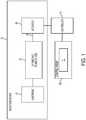
FIG. 1 is a schematic diagram of a fluid delivery device of the present invention;FIGS. 2A-2C are a series of cross-sectional views of a first embodiment of the fluid delivery device of the present invention;FIGS. 3A and3B are a series of cross-sectional views of a second embodiment of the fluid delivery device of the present invention; andFIGS. 4A-4C are a series of cross-sectional views of a third embodiment of the fluid delivery device of the present invention.- For purposes of the description hereinafter, the terms "upper", "lower", "right", "left", "vertical", "horizontal", "top", "bottom", "lateral", "longitudinal", and derivatives thereof, shall relate to the device of the present disclosure as it is oriented in the drawing figures. However, it is to be understood that the device of the present disclosure may assume various alternative variations, except where expressly specified to the contrary. It is also to be understood that the specific devices illustrated in the attached drawings, and described in the following specification, are simply exemplary embodiments of the device of the present disclosure. Hence, specific dimensions and other physical characteristics related to the embodiments disclosed herein are not to be considered as limiting.
- In general, the present invention provides infusion or injection devices and systems that are relatively easy to operate. The injection devices disclosed herein are related to the injection devices disclosed in United States Patent No.
7,632,245 and United States Patent No.9,486,573 13/826,483 - In the embodiment of the present invention illustrated in
FIG. 1 , an injection orinfusion device 10 includes a fluid-filled cartridge40 (for example, a vial, a prefilled syringe, or another suitable fluid delivery device) in which a fluid for injection into a patient is stored.Injection device 10 includes anoutlet 30 in fluid connection with a syringe andplunger rod combination 20 and through which fluid exits the syringe to be injected into the patient.Injection device 10 also includes the syringe andplunger rod combination 20 through which force/pressure, via a vacuum, is applied to the fluid that is drawn from the fluid-filledcartridge 40 into a portion of the syringe to cause the pressurized fluid to exitoutlet 30.Injection device 10 further includes anactuator 50 to initiate (and, possibly, terminate) flow.Actuator 50 can, for example, be operated by acontroller 70 via aremote controller 71 from, for example,control room 90. - The
actuator 50 can, for example, include a rotary valve at a syringe tip, a pinch valve with tubing, a ratchet valve, a fusible link, a trumpet valve, a port closing valve, a pump system, or a drive system to allow fluid to flow throughoutlet 30. The mechanism for operating the actuator50 (or imparting motion thereto to change a state) can, for example, include a vacuum drive, a piezoelectric drive, an electric motor drive (for example, an inside-MRI bore air core motor in which the magnet of the bore forms part of the motor), a solenoid drive, an electric motor drive outside of the bore, an electro-resistive pump, a charged ion pump (available, for example, from Exigent), a magneto restrictive material (to which a voltage is applied), a thermochemical activated motion (TCAM) material or device, a nitinol material, a state transition (liquid to gas), a bimetallic material (with different rates of expansion for each metal), an electro-active polymeric material, pneumatic or hydraulic pressure, and/or gravity. Power can be supplied via, for example, vacuum power, chemical power, electrical power (for example,
battery power, wall outlet power), power from the scanner, human/manual power, compressed or pressurized gas (for example, CO2 or air) power, hydraulic power, spring power, gravity power, or light/photoelectric power. In the embodiments described hereinafter, theactuator 50 is desirably a normally-closed valve. - The
controller 70 can, for example, control the state of theactuator 50 via ultrasound (for example, via a piezo tweeter operating through glass); via a scanner coil protocol (for example, GE/Siemens scanners comprise approximately 85% of the axial market and include two 15 volt connections); via microwave energy (for example, a glass smart link); via a mechanical or cable link (for example, via camera-type cable link using a plastic cable); via infrared light; via fiber optic cable; via pneumatic power; via hydraulic power; via patient operation; via voice activation; via movement of a table upon which a patient is positioned; via time delay; via an RF gradient trigger from scanner (for example, 5th shim tune); via a photo cell; via optical light control; via line power (for example, via audio frequency through panel); via an RF link, or via operator manual control (that is, sending the operator into the MRI room to activate the device). - For use in an MR environment, the components of the
injection device 10 are desirably fabricated from materials that are non-magnetic, non-ferrous, and/or otherwise suitable or compatible for use in an MRI environment. In general, many devices, including but not limited to many injectors and infusion pumps, that contain electric actuators such as DC brush motors, step motors, brushless DC motors, or other wound coil motors and solenoids, often fail in a strong magnetic field as a result of damage to internal permanent magnets. Moreover, currents induced within the field windings of such devices from electromagnetic fields can cause overheating and potential damage to the windings and any connected electronic circuitry. The MRI magnetic field can also interfere with the device-created magnetic field and prevent accurate operation. - Furthermore, differences in magnetic permeability of materials within the actuator and eddy currents induced within actuator windings can affect the homogeneity or uniformity of the MRI magnetic field, generating image artifacts. Actuators that use mechanical commutation, such as DC brush motors, can also generate radio frequency energy during switching, which can induce unwanted artifacts upon the acquired MRI images.
- With reference to
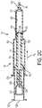
FIGS. 2A-2C and with continued reference toFIG. 1 , theinjection device 10 is desirably provided as a prepackaged system that is autoclaved sterilized. Theinjection device 10 includes an MR contrast vial100 (as the fluid-filled cartridge) having a septum sealedoutlet 102. Theinjection device 10 also includes asyringe 104 having a substantiallycylindrical syringe barrel 106 anopen end 108 and afluid dispensing end 110; and aplunger rod 111 configured to be received within theopen end 108 of thesyringe barrel 106. As discussed in greater detail hereinafter, thecylindrical syringe barrel 106 is divided into adelivery chamber 112 and avacuum drive chamber 114. Desirably, thedelivery chamber 112 may have a first diameter and thevacuum drive chamber 114 may have a second diameter that is greater than the first diameter as shown inFIGS. 2A-2C ; however, this is not to be construed as limiting the present invention as both chambers may have the same diameter. - The
plunger rod 111 includes: afirst end 116 having a sealing member, such as O-ring 118, provided in sealing engagement with aninner wall 120 of thesyringe barrel 106 to form thedelivery chamber 112 between thefirst end 116 of theplunger rod 111 and thefluid dispensing end 110 of thesyringe barrel 106; and asecond end 122 extending out ofopen end 108 of thesyringe barrel 106. Thesecond end 122 of theplunger rod 111 has a vial-receivingchamber 124 formed therein. A connection mechanism, such as aspike 126, is positioned within the vial-receivingchamber 124 for connecting theoutlet 102 of thevial 100 thereto. In the prepackaged system described hereinabove, thevial 100 is provided in the vial-receivingchamber 124 during the manufacturing process and aflexible seal 128 is positioned over thesecond end 122 of theplunger rod 111 to maintain sterility of the contrast provided in thevial 100. In operation, a user engages theoutlet 102 of thevial 100 with thespike 126 by applying pressure to theflexible seal 128. However, this is not to be construed as limiting the present invention as thevial 100 and the syringe/plunger rod combination may be provided as separate components with thesecond end 122 of theplunger rod 111 having an opening to allow the user to position avial 100 within the vial-receivingchamber 124. - The
plunger rod 111 further includes anintermediate sealing member 130 in sealing engagement with theinner wall 120 of thesyringe barrel 106. Theintermediate sealing member 130 is positioned between thefirst end 116 and thesecond end 122 of theplunger rod 111 such that thevacuum drive chamber 114 is provided between theintermediate sealing member 130 and thefirst end 116 of theplunger rod 111. In addition, if thevacuum drive chamber 114 and thedelivery chamber 112 are provided with different diameters as discussed hereinabove and shown inFIGS. 2A-2C , then thefirst end 116 of theplunger rod 111 may be provided with a different diameter than theintermediate sealing member 130 andsecond end 122 of theplunger rod 111 as shown inFIGS. 2A-2C . - The
plunger rod 111 also includes: afluid channel 132 extending from thespike 126 to thefirst end 116 of theplunger rod 111; and a one-way check valve 134 positioned at thefirst end 116 of theplunger rod 111. While the plunger rod is disclosed herein as including a one-way check valve 134 positioned at thefirst end 116 of theplunger rod 111, this is not to be construed as limiting the present invention as thevalve 134 may be positioned anywhere along the length of thechannel 132. In addition, rather than utilizing a one-way check valve, a stopcock, a springloaded valve, or any other suitable valve may be utilized. - In addition, the
fluid delivery device 10 includes anactuator 50, as discussed hereinabove, connected to thefluid dispensing end 110 of thesyringe barrel 106. Desirably, theactuator 50 is a normally closed valve that may be manually operated or operated remotely via acontroller 70 andremote controller 71. - In operation, fluid is dispensed from the
vial 100 by connecting theoutlet 102 thereof to thespike 126 by either applying force to theflexible seal 128 for the prepackaged system as discussed hereinabove or by positioning thevial 100 manually into the vial-receivingchamber 124 and engaging theoutlet 102 thereof with thespike 126. This positions theoutlet 102 of thevial 100 in fluid communication withfluid channel 132. Next, thesecond end 122 of theplunger rod 111 is pulled back in the direction of arrowA1 to form a vacuum within thevacuum drive chamber 114. Due to the one-way check valve 134 at thefirst end 116 of theplunger rod 111 and thefluid channel 132 extending through thevacuum drive chamber 114 to thespike 126, the fluid from thevial 100 is drawn (by the vacuum) from thevial 100 into thedelivery chamber 112 as shown by arrowA2. Also, since the one-way check valve 134 is positioned at thefirst end 116 of theplunger rod 111 and theactuator 50 embodied as a normally closed valve positioned at thefluid dispensing end 110 of thesyringe barrel 106, the device stays charged (due to the vacuum in the vacuum drive chamber114) and does not deliver the fluid in thedelivery chamber 112 until theactuator 50 is switched. At this point, the operator switches the actuator50 (e.g., by opening the normally closed valve) from a first state in which fluid is prevented from flowing through thefluid dispensing end 110 of thesyringe barrel 106 to a second state causing theplunger rod 111 to move in the direction of arrowA3 to force the fluid within thedelivery chamber 112 out of thefluid dispensing end 110. - Furthermore, two or more of
injection device 10 described hereinabove can be "ganged together" with appropriate fluid path sets (not shown) to deliver multiple fluids to a patient (e.g., contrast followed by saline, stress agent followed by contrast followed by saline, etc.). - While the fluid-filled
cartridge 40 has been described hereinabove as acontrast vial 100, this is not to be construed as limiting the present invention as any suitable fluid delivery device may be utilized. For instance, a syringe (not shown) may be utilized. In such an instance, the connection mechanism may be embodied as a female luer connector (not shown) instead of aspike 126. - With reference to
FIG. 3A and3B , an alternative embodiment of aninjection device 200 includes: asyringe 202, adrive mechanism 204, and anactuator 50. Thesyringe 202 includes a substantiallycylindrical syringe barrel 206 having afluid dispensing end 208 and anopen end 210 and aplunger 212 configured to be received within theopen end 210 of thesyringe barrel 206. - The
drive mechanism 204 includes a substantiallycylindrical body 214 having amovable member 216 positioned therein to form achamber 218 between themovable member 216 and a substantially closedfirst end 220 of thecylindrical body 214. Themovable member 216 includes aseal 222 which extends around a circumference thereof to fluidly isolate thechamber 218 from a second end of thecylindrical body 214. - The
drive mechanism 204 also includes aplunger rod 224 connected to afirst side 226 of themovable member 216 and extends through thefirst end 220 of thebody 214. Aseal 228 is provided between thefirst end 220 and theplunger rod 224 to prevent fluid from leaving thecylindrical body 214. Theplunger rod 224 is configured to operatively engage arear end 230 of theplunger 212 through a threaded or other type of connection. Thedrive mechanism 204 further includes alocking mechanism 232 configured to secure theopen end 210 of thesyringe 202 to the substantially closedfirst end 220 of thebody 214. Thedrive mechanism 204 may be embodied as a disposable device where thelocking mechanism 232 locks thesyringe 202 onto thebody 214 such that it cannot be removed. - In addition, the
fluid delivery device 200 includes anactuator 50, as discussed hereinabove, connected to thefluid dispensing end 208 of thesyringe barrel 206. Desirably, theactuator 50 is a normally closed valve that may be manually operated or operated remotely via acontroller 70 andremote controller 71. - In operation, fluid is dispensed from the
syringe 202 by connecting thesyringe 202 to theplunger rod 224 by threadedly connecting a first end of theplunger rod 224 to theplunger 212. Thereafter, theopen end 210 of thesyringe 202 is forced into thelocking mechanism 232 by moving thesyringe 202 in the direction of arrowB1, thereby moving themovable member 216 towards the second end of thecylindrical body 214 which forms a vacuum within thechamber 218. At this point, the operator switches the actuator50 (e.g., by opening the normally closed valve) from a first state in which fluid is prevented from flowing through thefluid dispensing end 208 of thesyringe barrel 206 to a second state causing themovable member 216, theplunger rod 224, and theplunger 212 to move in the direction of arrowB2 to force the fluid within thesyringe 202 out of thefluid dispensing end 208. - The
syringe 202 for the injection fluid (generally an MR contrast fluid) can, for example, be a polymeric or glass MR syringe available, for example, from Bayer HealthCare LLC of Indianola, Pa. Such syringes can be purchased "prefilled" with injection fluid or can be purchased empty and filled at the MRI site. The fluid in such syringes is pressurized via theplunger 212, which is slidably disposed within thesyringe barrel 206. - With reference to
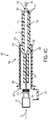
FIGS. 4A-4C , another alternative embodiment of theinjection device 300 is illustrated. Theinjection device 300 is desirably provided as a prepackaged system that is sterilized. Theinjection device 300 includes an MR contrast vial301 (as the fluid-filled cartridge) having a septum sealedoutlet 302. Theinjection device 300 also includes asyringe 304 having a substantiallycylindrical syringe barrel 306 that includes a fluid receiving end (i.e., open end308) and afluid dispensing end 310 and aplunger rod 311 configured to be received within theopen end 308 of thesyringe barrel 306. As discussed in greater detail hereinafter, thecylindrical syringe barrel 306 is divided into a delivery chamber312 (inFIGS. 4A-4C the plunger rod is positioned within the deliver chamber) and avacuum drive chamber 314. Desirably, the delivery chamber may have a first diameter and thevacuum drive chamber 314 may have a second diameter that is greater than the first diameter as shown inFIGS. 4A-4C ; however, this is not to be construed as limiting the present invention as both chambers may have the same diameter. In addition, while theinjection device 300 is described hereinabove, this is not to be construed as limiting the present invention as any suitable fluid container may be utilized. - The
plunger rod 311 includes: afirst end 316 having a sealing member, such as O-ring 318, provided in sealing engagement with an inner wall of thesyringe barrel 306 to form thedelivery chamber 312 between thefirst end 316 of theplunger rod 311 and thefluid dispensing end 310 of thesyringe barrel 306; and asecond end 322 extending out ofopen end 308 of thesyringe barrel 306. Thesecond end 322 of theplunger rod 311 has a connection mechanism, such as aspike 323, extending therefrom and comprising a fluid path extending from afirst end 324 of thespike 323 to asecond end 325 of thespike 323 in fluid communication with thedelivery chamber 312 of thesyringe 304. Acompressible member 326 extends from theoutlet 302 of thevial 301 to theopen end 308 of thesyringe barrel 306 and surrounds at least thefirst end 324 of thespike 323. Aremovable retention mechanism 327 is positioned between theoutlet 302 of thevial 301 and theopen end 308 of thesyringe barrel 306 over the compressible member to prevent theoutlet 302 of thevial 301 from contacting thespike 323. - In operation, a user removes the retention mechanism in the direction of arrowC1 as shown in
FIG. 4B . A user then engages theoutlet 302 of thevial 301 with thespike 323 by applying pressure to thevial 301 in the direction of arrowC2 as shown inFIG. 4C , thereby compressing thecompressible member 326. - The
plunger rod 311 further includes anintermediate sealing member 330 in sealing engagement with the inner wall of thesyringe barrel 306. Theintermediate sealing member 330 is positioned between thefirst end 316 and thesecond end 322 of theplunger rod 311 such that thevacuum drive chamber 314 is provided between theintermediate sealing member 330 and thefirst end 316 of theplunger rod 311. In addition, if thevacuum drive chamber 314 and thedelivery chamber 312 are provided with different diameters as discussed hereinabove and shown inFIGS. 4A-4C , then thefirst end 316 of theplunger rod 311 may be provided with a different diameter than theintermediate sealing member 330 andsecond end 322 of theplunger rod 311 as shown inFIGS. 4A-4C . - The
plunger rod 311 also includes: afluid channel 332 extending from thesecond end 325 of thespike 323 to thefirst end 316 of theplunger rod 311; and a one-way check valve positioned at thefirst end 316 of theplunger rod 311. - In addition, the
injection device 300 includes anactuator 50, as discussed hereinabove, connected to thefluid dispensing end 310 of thesyringe barrel 306. Desirably, theactuator 50 is a normally closed valve that may be manually operated or operated remotely via acontroller 70 andremote controller 71. - In operation, fluid is dispensed from the
vial 301 by connecting theoutlet 302 thereof to thespike 323 as discussed hereinabove. This positions theoutlet 302 of thevial 301 in fluid communication withfluid channel 332. Next, theinjection device 300 is operated in the same manner as theinjection device 10 as discussed in detail hereinabove. - Desirably, the injection devices discussed hereinabove are suitable to be placed within one foot of the MRI bore. More desirably, the injection devices of the present disclosure are suitable to be placed within the bore, thereby providing close access to the injection site on the patient and eliminating lengthy connective tubing used with many currently available injection devices. In general, to be "MR compatible" as that phrase is used herein, the materials of
injection device 10,injection device 200, andinjection device 300 should not interfere with the operation of an MR scanner in a substantial manner (for example, to cause image artifacts). Additionally, the MR environment (for example, the powerful magnetic field) should not substantially interfere with the operation of theinjection device 10,injection device 200, andinjection device 300. Examples of suitable MRI compatible materials forinjection device 10,injection device 200, andinjection device 300 include, but are not limited to, polymeric materials, glass materials, and aluminum. - While specific embodiments of the device of the present disclosure have been described in detail, it will be appreciated by those skilled in the art that various modifications and alternatives to those details could be developed in light of the overall teachings of the disclosure. Accordingly, the particular arrangements disclosed are meant to be illustrative only and not limiting as to the scope of the device of the present disclosure which is to be given the full breadth of the claims appended and any and all equivalents thereof.
Claims (9)
- A fluid delivery device comprising:a fluid-filled cartridge (301) comprising an outlet (302);a fluid container (304) comprising a substantially cylindrical barrel (306) having an open end (308) and a fluid dispensing end (310);a connection mechanism extending from the open end (308) of the cylindrical barrel (306) and comprising a fluid path extending from a first end of the connection mechanism to a second end of the connection mechanism in fluid communication with the open end (308) of the cylindrical barrel (306);a plunger rod (311) configured to be received within the open end (308) of the cylindrical barrel (306) and comprising a first end (316) and a second end (322) extending out of the open end (308) of the cylindrical barrel (306), the plunger rod (311) dividing the cylindrical barrel (306) into a first chamber between a first end (316) of the plunger rod and the fluid dispensing end (310) of the cylindrical barrel (306) and a second chamber;an intermediate sealing member (330) in sealing engagement with an inner wall of the cylindrical barrel (306), the intermediate sealing member (330) positioned between the first end (316) and the second end (322) of the plunger rod (311) to form the second chamber;a compressible member (326) extending from the outlet (302) of the fluid-filled cartridge (301) to the open end (308) of the cylindrical barrel (306) and surrounding the connection mechanism;a removable retention mechanism (327) positioned between the outlet (302) of the fluid-filled cartridge (301) and the open end (308) of the cylindrical barrel (306) over the compressible member (326) to prevent the outlet (302) of the fluid-filled cartridge (301) from contacting the connection mechanism,an actuator (50) connected to the fluid dispensing end (310) of the syringe barrel (306), having a first state in which fluid is prevented from flowing through the fluid dispensing end (310) of the syringe (304) and a second state that allows the fluid to flow through the fluid dispensing end (310),wherein fluid is transferred from the fluid-filled cartridge (301) to the fluid container (304) by removing the removable retention mechanism (327) and compressing the compressible member (326) such that the outlet (302) of the cartridge (301) is connected to the connection mechanism, thereby providing the cartridge (301) in fluid communication with the fluid path extending from the first end of the connection mechanism to the second end of the connection mechanism in fluid communication with the open end (308) of the cylindrical barrel (306), andwherein fluid is dispensed by forming a vacuum within the second chamber by enlarging a volume of the second chamber by pulling the second end (322) of the plunger rod (311) away from the open end (308) of the cylindrical barrel (306), thereby drawing the fluid from the cartridge (301) through the fluid channel (332) and into the first chamber, and switching the actuator (50) from the first state in which the fluid is prevented from flowing through the fluid dispensing end (310) of the syringe (304) to the second state to allow the fluid to flow through the fluid dispensing end (310).
- The fluid delivery device of claim 1, wherein the fluid container is a syringe.
- The fluid delivery device of claim 1, wherein:the first end (316) of the plunger rod has a sealing member (318) provided in sealing engagement with the inner wall of the cylindrical barrel (306) such that the first chamber is provided between the first end (316) of the plunger rod (311) and the fluid dispensing end (310) of the cylindrical barrel (306);the connection mechanism is positioned within the second end (322) of the plunger rod (311);a fluid channel (332) of the plunger rod (311) forms part of the fluid path extending from the second end (322) of the connection mechanism to the first end (316) of the plunger rod (311).
- The fluid delivery device of claim 3, wherein the first chamber has a first diameter and the second chamber has a second diameter that is greater than the first diameter.
- The fluid delivery device of claim 3 or 4, wherein a mechanism of the actuator (50) comprises a rotary valve, a pinch valve with tubing, a ratchet valve, a fusible link, a trumpet valve, a port closing valve, a pump system, or a drive system.
- The fluid delivery device of any of claims 3 to 5, further comprising a controller (70) configured to remotely control the state of the actuator (50).
- The fluid delivery device of claim 6, wherein the controller (70) controls the state of the actuator (50) via ultrasound, via a protocol of an imaging scanner, via microwave energy, via a mechanical link, via infrared light, via fiber optic cable, via pneumatic power, via hydraulic power, via voice activation, via movement of a scanner table, via time delay, via an RF gradient trigger from a scanner, via a photo cell, via optical light, via an RF signal, or via line power.
- The fluid delivery device of any of claims 3 to 7, wherein the fluid-filled cartridge (301), the fluid container (304), the plunger rod (311), and the actuator (50) are MR compatible, thereby making the device suitable for use in or near a bore of an MR scanner.
- The fluid delivery device of any preceding claim, wherein the fluid-filled cartridge (301) is a vial and the connection mechanism is a spike (323).
Priority Applications (2)
| Application Number | Priority Date | Filing Date | Title |
|---|---|---|---|
| EP19165133.0AEP3527190B1 (en) | 2013-07-17 | 2014-07-15 | Cartridge-based in-bore infuser |
| DK19165133.0TDK3527190T3 (en) | 2013-07-17 | 2014-07-15 | CARTRIDGE-BASED INFUSION DEVICE IN A TUNNEL |
Applications Claiming Priority (2)
| Application Number | Priority Date | Filing Date | Title |
|---|---|---|---|
| US201361847323P | 2013-07-17 | 2013-07-17 | |
| PCT/US2014/046618WO2015009673A2 (en) | 2013-07-17 | 2014-07-15 | Cartridge-based in-bore infuser |
Related Child Applications (2)
| Application Number | Title | Priority Date | Filing Date |
|---|---|---|---|
| EP19165133.0ADivisionEP3527190B1 (en) | 2013-07-17 | 2014-07-15 | Cartridge-based in-bore infuser |
| EP19165133.0ADivision-IntoEP3527190B1 (en) | 2013-07-17 | 2014-07-15 | Cartridge-based in-bore infuser |
Publications (3)
| Publication Number | Publication Date |
|---|---|
| EP3021813A2 EP3021813A2 (en) | 2016-05-25 |
| EP3021813A4 EP3021813A4 (en) | 2017-04-05 |
| EP3021813B1true EP3021813B1 (en) | 2019-05-15 |
Family
ID=52346822
Family Applications (2)
| Application Number | Title | Priority Date | Filing Date |
|---|---|---|---|
| EP14825990.6AActiveEP3021813B1 (en) | 2013-07-17 | 2014-07-15 | Cartridge-based in-bore infuser |
| EP19165133.0AActiveEP3527190B1 (en) | 2013-07-17 | 2014-07-15 | Cartridge-based in-bore infuser |
Family Applications After (1)
| Application Number | Title | Priority Date | Filing Date |
|---|---|---|---|
| EP19165133.0AActiveEP3527190B1 (en) | 2013-07-17 | 2014-07-15 | Cartridge-based in-bore infuser |
Country Status (11)
| Country | Link |
|---|---|
| US (2) | US10537675B2 (en) |
| EP (2) | EP3021813B1 (en) |
| JP (1) | JP2016527954A (en) |
| KR (1) | KR20160061920A (en) |
| CN (1) | CN105358115A (en) |
| AU (2) | AU2014290270B2 (en) |
| BR (1) | BR112016000769A2 (en) |
| CA (1) | CA2912932A1 (en) |
| DK (2) | DK3021813T3 (en) |
| RU (1) | RU2016105099A (en) |
| WO (1) | WO2015009673A2 (en) |
Families Citing this family (5)
| Publication number | Priority date | Publication date | Assignee | Title |
|---|---|---|---|---|
| CN108392417B (en)* | 2018-04-08 | 2023-09-01 | 中国人民解放军总医院 | Hand-held dispensing device |
| AU2019255183B2 (en)* | 2018-04-19 | 2022-09-29 | Becton, Dickinson And Company | Self-pumping syringe |
| US20200009017A1 (en)* | 2018-07-09 | 2020-01-09 | Vivek K. Sharma | Multi-volume drug delivery system with vacuum-assisted mixing and/or delivery |
| CN111781318B (en)* | 2020-08-26 | 2024-06-28 | 广东汕泰食品有限公司 | Safety detection device and detection method for jumping food |
| US12226776B2 (en) | 2021-11-04 | 2025-02-18 | Instrumentation Laboratory Company | Preparing substances in a medical diagnostic system |
Family Cites Families (87)
| Publication number | Priority date | Publication date | Assignee | Title |
|---|---|---|---|---|
| US1367008A (en) | 1917-04-09 | 1921-02-01 | Alfred N Bessese | Syringe |
| US3570486A (en)* | 1968-10-14 | 1971-03-16 | Horizon Ind Ltd | Mixing syringe |
| US3724460A (en)* | 1968-11-14 | 1973-04-03 | American Home Prod | Disposable cartridge for admixing two components of injectable medicament |
| US4006736A (en) | 1974-11-27 | 1977-02-08 | Medrad, Inc. | Angiographic injector |
| US4014330A (en)* | 1975-10-28 | 1977-03-29 | Abbott Laboratories | Disposable two-compartment syringe |
| US4171698A (en)* | 1977-08-15 | 1979-10-23 | Abbott Laboratories | Prefilled two-compartment syringe |
| US4161178A (en)* | 1977-12-08 | 1979-07-17 | Abbott Laboratories | Additive transfer device |
| FR2468377A1 (en) | 1979-11-06 | 1981-05-08 | Bourdon Frederic | SYRINGE OPERATING WITH AN EXTERNAL ENERGY SOURCE |
| US4367737A (en) | 1981-04-06 | 1983-01-11 | George Kozam | Multiple barrel syringe |
| ATE51525T1 (en) | 1984-06-06 | 1990-04-15 | Medrad Inc | ANGIOGRAPHY INJECTOR AND ANGIOGRAPHY SYRINGE USABLE WITH THEM. |
| US4693706A (en)* | 1986-08-11 | 1987-09-15 | Mark L. Anderson | Two compartment mixing syringe |
| US5033650A (en) | 1987-03-09 | 1991-07-23 | Laurence Colin | Multiple barrel dispensing device |
| DE3873579T2 (en)* | 1987-04-02 | 1993-03-18 | Drg Flexpak Ltd | DEVICE FOR MATCHING SUBSTANCES, LIKE MEDICINAL PRODUCTS, WITH A LIQUID. |
| US4936315A (en) | 1988-10-20 | 1990-06-26 | Lineback Paul I | Methods and apparatus for obtaining arterial blood samples |
| US4944726A (en) | 1988-11-03 | 1990-07-31 | Applied Vascular Devices | Device for power injection of fluids |
| JP2577800B2 (en) | 1989-08-19 | 1997-02-05 | 三菱電機株式会社 | Automotive DC power supply current detector |
| US5135500A (en) | 1989-10-31 | 1992-08-04 | Prime Medical Products, Inc. | Self-driven pump device |
| SE9002510D0 (en) | 1990-07-26 | 1990-07-26 | Kabivitrum Ab | APPARATUS FOR CONTROLLED DELIVERY OF LIQUIDS |
| US5067948A (en)* | 1990-09-27 | 1991-11-26 | Habley Medical Technology Corporation | Safety, packaging, injection and disposal system for pre-filled pharmaceutical vials |
| US5151093A (en) | 1990-10-29 | 1992-09-29 | Alza Corporation | Osmotically driven syringe with programmable agent delivery |
| GB9027422D0 (en) | 1990-12-18 | 1991-02-06 | Scras | Osmotically driven infusion device |
| JP3003949B2 (en) | 1990-12-21 | 2000-01-31 | ヘキスト・マリオン・ルセル株式会社 | Medical container |
| US5176642A (en) | 1991-03-11 | 1993-01-05 | Mectra Labs, Inc. | Vacuum powdered syringe |
| JP2562492Y2 (en) | 1991-08-30 | 1998-02-10 | 株式会社パイオラックス | Continuous chemical injector |
| US5279585A (en) | 1992-02-04 | 1994-01-18 | Becton, Dickinson And Company | Medication delivery pen having improved dose delivery features |
| US5330426A (en)* | 1992-08-13 | 1994-07-19 | Science Incorporated | Mixing and delivery syringe assembly |
| US5383858B1 (en) | 1992-08-17 | 1996-10-29 | Medrad Inc | Front-loading medical injector and syringe for use therewith |
| JP3293184B2 (en) | 1992-08-24 | 2002-06-17 | 日本たばこ産業株式会社 | Discharge device of cigarette making machine with filter |
| JP2555163Y2 (en) | 1993-03-25 | 1997-11-19 | 昭和電工株式会社 | Infusion container |
| US5417213A (en) | 1993-06-07 | 1995-05-23 | Prince; Martin R. | Magnetic resonance arteriography with dynamic intravenous contrast agents |
| US5398850A (en) | 1993-08-06 | 1995-03-21 | River Medical, Inc. | Gas delivery apparatus for infusion |
| RU2141306C1 (en)* | 1993-09-07 | 1999-11-20 | Дебиотек С.А. | Syringe device for mixing of two components |
| US5494036A (en) | 1993-11-26 | 1996-02-27 | Medrad, Inc. | Patient infusion system for use with MRI |
| EP0715861B1 (en)* | 1994-04-27 | 2000-08-02 | Daiken Iki Co. Ltd. | Liquid injection device |
| US5840026A (en) | 1994-09-21 | 1998-11-24 | Medrad, Inc. | Patient specific dosing contrast delivery systems and methods |
| US5746724A (en)* | 1995-04-13 | 1998-05-05 | Advanced Cytometrix, Inc. | Aspiration needle apparatus incorporating its own vacuum and method and adapter for use therewith |
| US6656157B1 (en) | 1995-04-20 | 2003-12-02 | Acist Medical Systems, Inc. | Infinitely refillable syringe |
| DK0928182T3 (en) | 1996-01-11 | 2002-08-26 | Duoject Inc | Delivery system for medicines packed in pharmaceutical bottles |
| FR2753624B1 (en)* | 1996-09-25 | 1999-04-16 | Biodome | CONNECTION DEVICE, PARTICULARLY BETWEEN A CONTAINER WITH PERFORABLE CAP AND A SYRINGE |
| US5911252A (en) | 1997-04-29 | 1999-06-15 | Cassel; Douglas | Automated syringe filling system for radiographic contrast agents and other injectable substances |
| MY125849A (en) | 1997-07-25 | 2006-08-30 | Alza Corp | Osmotic delivery system, osmotic delivery system semipermeable body assembly, and method for controlling delivery rate of beneficial agents from osmotic delivery systems |
| JP3416943B2 (en) | 1998-03-27 | 2003-06-16 | ニプロ株式会社 | Chemical solution injection device using negative pressure |
| AR021220A1 (en)* | 1998-09-15 | 2002-07-03 | Baxter Int | CONNECTION DEVICE FOR ESTABLISHING A FLUID COMMUNICATION BETWEEN A FIRST CONTAINER AND A SECOND CONTAINER. |
| WO2001000261A1 (en)* | 1999-06-30 | 2001-01-04 | Baxter International Inc. | Syringe for transfer of medication from a prefilled medication container |
| US6413238B1 (en) | 1999-09-17 | 2002-07-02 | Baxter International Inc | Fluid dispenser with stabilized fluid flow |
| US6299767B1 (en) | 1999-10-29 | 2001-10-09 | Waters Investments Limited | High pressure capillary liquid chromatography solvent delivery system |
| US6425885B1 (en) | 1999-12-20 | 2002-07-30 | Ultradent Products, Inc. | Hydraulic syringe |
| US7470228B2 (en) | 2000-04-14 | 2008-12-30 | Attenuex Technologies, Inc. | Method of treating benign hypertrophy of the prostate |
| JP2001333980A (en) | 2000-05-26 | 2001-12-04 | Ookisu:Kk | Continuous liquid medicine injector |
| US6704592B1 (en) | 2000-06-02 | 2004-03-09 | Medrad, Inc. | Communication systems for use with magnetic resonance imaging systems |
| US20050107738A1 (en) | 2000-07-21 | 2005-05-19 | Slater Charles R. | Occludable intravascular catheter for drug delivery and method of using the same |
| IL137448A (en) | 2000-07-23 | 2006-08-01 | Flomed Ltd | System and method for ensuring continuous fluid flow through a main conduit |
| JP2002035125A (en) | 2000-07-27 | 2002-02-05 | Daiken Iki Kk | Vacuum driven pump and liquid injection device using this pump |
| US6387228B1 (en) | 2000-08-03 | 2002-05-14 | Henri J. R. Maget | Electrochemical generation of carbon dioxide and hydrogen from organic acids |
| US6387077B1 (en) | 2000-10-13 | 2002-05-14 | Mallinckrodt Inc. | Apparatus and method for providing a suspended agent |
| WO2002070049A1 (en) | 2001-02-08 | 2002-09-12 | Medrad, Inc. | Syringe loading devices for use with syringes and medical injectors |
| US7566320B2 (en) | 2001-02-14 | 2009-07-28 | Acist Medical Systems, Inc. | Fluid injector system |
| US7407490B2 (en)* | 2001-11-29 | 2008-08-05 | Novo Nordisk A/S | Delivery device and cartridge therefore |
| JP2003235938A (en)* | 2002-02-21 | 2003-08-26 | Taisei Kako Co Ltd | Infusion vessel |
| US20050075581A1 (en) | 2002-04-23 | 2005-04-07 | Jeffrey Schwindt | Pneumatic circuit |
| US7678333B2 (en)* | 2003-01-22 | 2010-03-16 | Duoject Medical Systems Inc. | Fluid transfer assembly for pharmaceutical delivery system and method for using same |
| WO2004064706A2 (en)* | 2003-01-22 | 2004-08-05 | Duoject Medical Systems Inc. | Pharmaceutical delivery systems and methods for using same |
| EP2489378A1 (en) | 2003-02-21 | 2012-08-22 | Smith and Nephew, Inc. | Spinal fluid introduction |
| US8016798B2 (en) | 2003-02-24 | 2011-09-13 | Integrated Sensing Systems, Inc. | Fluid delivery system and sensing unit therefor |
| US7824373B2 (en) | 2003-05-28 | 2010-11-02 | Ducksoo Kim | Self-contained power-assisted syringe |
| EP1635896A1 (en)* | 2003-06-20 | 2006-03-22 | Allergan, Inc. | Needless injectors |
| US7315109B1 (en) | 2003-08-15 | 2008-01-01 | Medrad, Inc. | Actuators and fluid delivery systems using such actuators |
| US7632245B1 (en) | 2003-08-18 | 2009-12-15 | Medrad, Inc. | Devices, systems and methods for delivery of a fluid into a patient during a magnetic resonance procedure |
| US20050084395A1 (en) | 2003-10-17 | 2005-04-21 | Kang Jing X. | Vacuum driven pump for a lavage instrument |
| US7635346B2 (en) | 2004-01-09 | 2009-12-22 | G. I. View Ltd. | Pressure-propelled system for body lumen |
| US20050209790A1 (en) | 2004-03-19 | 2005-09-22 | Matthias Niethammer | Method and apparatus for remote servicing of an external component of an installed medical system |
| US7731678B2 (en)* | 2004-10-13 | 2010-06-08 | Hyprotek, Inc. | Syringe devices and methods for mixing and administering medication |
| CN100502962C (en)* | 2004-10-27 | 2009-06-24 | 杨章民 | safety syringe |
| WO2006124634A1 (en) | 2005-05-16 | 2006-11-23 | Mallinckrodt Inc. | Multi-barrel syringe having integral manifold |
| US7846135B2 (en)* | 2006-02-24 | 2010-12-07 | Midland Medical Holding LLC | Retractable needle syringe with needle trap |
| US20080097389A1 (en) | 2006-07-10 | 2008-04-24 | Wilson Roland B | Y-type blood transfusion set |
| CN101244297B (en)* | 2007-02-14 | 2010-09-08 | 丁玉英 | Automatic medicine mixing device for powder injection |
| GB2461086B (en)* | 2008-06-19 | 2012-12-05 | Cilag Gmbh Int | Injection device |
| CA2951841C (en) | 2008-07-18 | 2018-07-10 | Becton, Dickinson And Company | Dual chamber and gear pump assembly for a high pressure delivery system |
| WO2010091132A1 (en) | 2009-02-04 | 2010-08-12 | Mallinckrodt Inc. | Hand-actuated syringe with vacuum chamber for auto refill |
| US9399095B2 (en)* | 2009-05-27 | 2016-07-26 | David R. Duncan | Compact non-electric medicament infuser |
| US8992505B2 (en) | 2011-04-18 | 2015-03-31 | Thorne Consulting & Intellectual Property, LLC | Medical syringe filling and valving |
| US9078978B2 (en)* | 2011-12-28 | 2015-07-14 | Stat Medical Devices, Inc. | Needle assembly with safety system for a syringe or fluid sampling device and method of making and using the same |
| WO2014004511A1 (en) | 2012-06-28 | 2014-01-03 | Saint-Gobain Performance Plastics Corporation | Polymer bellows spring |
| PL2732770T3 (en)* | 2012-11-16 | 2016-12-30 | Needle-free injection device | |
| US9101713B2 (en) | 2013-03-12 | 2015-08-11 | Bayer Medical Care Inc. | Constant force syringe |
| US9486573B2 (en) | 2013-03-14 | 2016-11-08 | Bayer Healthcare Llc | Fluid delivery system and method of fluid delivery to a patient |
- 2014
- 2014-07-15CACA2912932Apatent/CA2912932A1/ennot_activeAbandoned
- 2014-07-15AUAU2014290270Apatent/AU2014290270B2/ennot_activeCeased
- 2014-07-15EPEP14825990.6Apatent/EP3021813B1/enactiveActive
- 2014-07-15CNCN201480038697.XApatent/CN105358115A/enactivePending
- 2014-07-15KRKR1020157036712Apatent/KR20160061920A/ennot_activeWithdrawn
- 2014-07-15RURU2016105099Apatent/RU2016105099A/ennot_activeApplication Discontinuation
- 2014-07-15WOPCT/US2014/046618patent/WO2015009673A2/enactiveApplication Filing
- 2014-07-15JPJP2016527022Apatent/JP2016527954A/enactivePending
- 2014-07-15DKDK14825990.6Tpatent/DK3021813T3/enactive
- 2014-07-15DKDK19165133.0Tpatent/DK3527190T3/enactive
- 2014-07-15BRBR112016000769Apatent/BR112016000769A2/ennot_activeApplication Discontinuation
- 2014-07-15USUS14/904,888patent/US10537675B2/enactiveActive
- 2014-07-15EPEP19165133.0Apatent/EP3527190B1/enactiveActive
- 2017
- 2017-08-18AUAU2017216590Apatent/AU2017216590A1/ennot_activeAbandoned
- 2020
- 2020-01-17USUS16/746,377patent/US11602591B2/enactiveActive
Non-Patent Citations (1)
| Title |
|---|
| None* |
Also Published As
| Publication number | Publication date |
|---|---|
| KR20160061920A (en) | 2016-06-01 |
| WO2015009673A2 (en) | 2015-01-22 |
| EP3527190B1 (en) | 2025-05-28 |
| CN105358115A (en) | 2016-02-24 |
| US20200147296A1 (en) | 2020-05-14 |
| EP3021813A2 (en) | 2016-05-25 |
| WO2015009673A3 (en) | 2015-04-16 |
| US10537675B2 (en) | 2020-01-21 |
| US20160151559A1 (en) | 2016-06-02 |
| DK3021813T3 (en) | 2019-07-15 |
| AU2017216590A1 (en) | 2017-09-07 |
| AU2014290270B2 (en) | 2017-06-22 |
| US11602591B2 (en) | 2023-03-14 |
| EP3527190A1 (en) | 2019-08-21 |
| DK3527190T3 (en) | 2025-07-21 |
| JP2016527954A (en) | 2016-09-15 |
| RU2016105099A3 (en) | 2018-06-18 |
| EP3021813A4 (en) | 2017-04-05 |
| AU2014290270A1 (en) | 2016-02-04 |
| RU2016105099A (en) | 2017-08-22 |
| CA2912932A1 (en) | 2015-01-22 |
| BR112016000769A2 (en) | 2018-03-20 |
Similar Documents
| Publication | Publication Date | Title |
|---|---|---|
| US11602591B2 (en) | Cartridge-based in-bore infuser | |
| US10543312B2 (en) | Fluid delivery system and method of fluid delivery to a patient | |
| US7632245B1 (en) | Devices, systems and methods for delivery of a fluid into a patient during a magnetic resonance procedure | |
| US7540854B2 (en) | Method of substituting a first fluid delivery device with a second fluid delivery device | |
| CN110869071B (en) | Method of dynamic pressure control in a fluid injector system | |
| KR20160072106A (en) | Magnetic pressure jacket for fluid injector | |
| CN105073162A (en) | multi-chamber syringe | |
| US20130338592A1 (en) | Medicament infusion device | |
| WO2002083208A2 (en) | Implantable therapeutic substance delivery device having a permanent magnet solenoid pump | |
| US20170182306A1 (en) | Magnetic Medical Connector And Fluid Transfer Set Including The Magnetic Medical Connector | |
| US10994071B2 (en) | Syringe adapter with concentric rings | |
| JP2018161507A (en) | One-way valve whose inflow operation is restricted, tube unit equipped with the one-way valve, and liquid medicine injection system | |
| JP4902096B2 (en) | Chemical syringe | |
| US20170007760A1 (en) | Injection device | |
| JP2018122034A (en) | Syringe holder, medical solution injection device, and use method of medical solution injection device |
Legal Events
| Date | Code | Title | Description |
|---|---|---|---|
| PUAI | Public reference made under article 153(3) epc to a published international application that has entered the european phase | Free format text:ORIGINAL CODE: 0009012 | |
| 17P | Request for examination filed | Effective date:20151216 | |
| AK | Designated contracting states | Kind code of ref document:A2 Designated state(s):AL AT BE BG CH CY CZ DE DK EE ES FI FR GB GR HR HU IE IS IT LI LT LU LV MC MK MT NL NO PL PT RO RS SE SI SK SM TR | |
| AX | Request for extension of the european patent | Extension state:BA ME | |
| DAX | Request for extension of the european patent (deleted) | ||
| A4 | Supplementary search report drawn up and despatched | Effective date:20170302 | |
| RIC1 | Information provided on ipc code assigned before grant | Ipc:A61J 1/20 20060101AFI20170224BHEP Ipc:A61M 5/20 20060101ALI20170224BHEP Ipc:A61M 5/178 20060101ALI20170224BHEP Ipc:B65D 47/00 20060101ALI20170224BHEP | |
| STAA | Information on the status of an ep patent application or granted ep patent | Free format text:STATUS: EXAMINATION IS IN PROGRESS | |
| 17Q | First examination report despatched | Effective date:20181015 | |
| GRAP | Despatch of communication of intention to grant a patent | Free format text:ORIGINAL CODE: EPIDOSNIGR1 | |
| STAA | Information on the status of an ep patent application or granted ep patent | Free format text:STATUS: GRANT OF PATENT IS INTENDED | |
| INTG | Intention to grant announced | Effective date:20190128 | |
| GRAS | Grant fee paid | Free format text:ORIGINAL CODE: EPIDOSNIGR3 | |
| GRAA | (expected) grant | Free format text:ORIGINAL CODE: 0009210 | |
| STAA | Information on the status of an ep patent application or granted ep patent | Free format text:STATUS: THE PATENT HAS BEEN GRANTED | |
| AK | Designated contracting states | Kind code of ref document:B1 Designated state(s):AL AT BE BG CH CY CZ DE DK EE ES FI FR GB GR HR HU IE IS IT LI LT LU LV MC MK MT NL NO PL PT RO RS SE SI SK SM TR | |
| REG | Reference to a national code | Ref country code:CH Ref legal event code:EP | |
| REG | Reference to a national code | Ref country code:DE Ref legal event code:R096 Ref document number:602014046946 Country of ref document:DE | |
| REG | Reference to a national code | Ref country code:IE Ref legal event code:FG4D | |
| REG | Reference to a national code | Ref country code:DK Ref legal event code:T3 Effective date:20190711 | |
| REG | Reference to a national code | Ref country code:NL Ref legal event code:FP | |
| REG | Reference to a national code | Ref country code:SE Ref legal event code:TRGR | |
| REG | Reference to a national code | Ref country code:LT Ref legal event code:MG4D | |
| PG25 | Lapsed in a contracting state [announced via postgrant information from national office to epo] | Ref country code:ES Free format text:LAPSE BECAUSE OF FAILURE TO SUBMIT A TRANSLATION OF THE DESCRIPTION OR TO PAY THE FEE WITHIN THE PRESCRIBED TIME-LIMIT Effective date:20190515 Ref country code:AL Free format text:LAPSE BECAUSE OF FAILURE TO SUBMIT A TRANSLATION OF THE DESCRIPTION OR TO PAY THE FEE WITHIN THE PRESCRIBED TIME-LIMIT Effective date:20190515 Ref country code:PT Free format text:LAPSE BECAUSE OF FAILURE TO SUBMIT A TRANSLATION OF THE DESCRIPTION OR TO PAY THE FEE WITHIN THE PRESCRIBED TIME-LIMIT Effective date:20190915 Ref country code:LT Free format text:LAPSE BECAUSE OF FAILURE TO SUBMIT A TRANSLATION OF THE DESCRIPTION OR TO PAY THE FEE WITHIN THE PRESCRIBED TIME-LIMIT Effective date:20190515 Ref country code:HR Free format text:LAPSE BECAUSE OF FAILURE TO SUBMIT A TRANSLATION OF THE DESCRIPTION OR TO PAY THE FEE WITHIN THE PRESCRIBED TIME-LIMIT Effective date:20190515 Ref country code:FI Free format text:LAPSE BECAUSE OF FAILURE TO SUBMIT A TRANSLATION OF THE DESCRIPTION OR TO PAY THE FEE WITHIN THE PRESCRIBED TIME-LIMIT Effective date:20190515 Ref country code:NO Free format text:LAPSE BECAUSE OF FAILURE TO SUBMIT A TRANSLATION OF THE DESCRIPTION OR TO PAY THE FEE WITHIN THE PRESCRIBED TIME-LIMIT Effective date:20190815 | |
| PG25 | Lapsed in a contracting state [announced via postgrant information from national office to epo] | Ref country code:RS Free format text:LAPSE BECAUSE OF FAILURE TO SUBMIT A TRANSLATION OF THE DESCRIPTION OR TO PAY THE FEE WITHIN THE PRESCRIBED TIME-LIMIT Effective date:20190515 Ref country code:BG Free format text:LAPSE BECAUSE OF FAILURE TO SUBMIT A TRANSLATION OF THE DESCRIPTION OR TO PAY THE FEE WITHIN THE PRESCRIBED TIME-LIMIT Effective date:20190815 Ref country code:GR Free format text:LAPSE BECAUSE OF FAILURE TO SUBMIT A TRANSLATION OF THE DESCRIPTION OR TO PAY THE FEE WITHIN THE PRESCRIBED TIME-LIMIT Effective date:20190816 Ref country code:LV Free format text:LAPSE BECAUSE OF FAILURE TO SUBMIT A TRANSLATION OF THE DESCRIPTION OR TO PAY THE FEE WITHIN THE PRESCRIBED TIME-LIMIT Effective date:20190515 | |
| REG | Reference to a national code | Ref country code:AT Ref legal event code:MK05 Ref document number:1132582 Country of ref document:AT Kind code of ref document:T Effective date:20190515 | |
| PG25 | Lapsed in a contracting state [announced via postgrant information from national office to epo] | Ref country code:SK Free format text:LAPSE BECAUSE OF FAILURE TO SUBMIT A TRANSLATION OF THE DESCRIPTION OR TO PAY THE FEE WITHIN THE PRESCRIBED TIME-LIMIT Effective date:20190515 Ref country code:RO Free format text:LAPSE BECAUSE OF FAILURE TO SUBMIT A TRANSLATION OF THE DESCRIPTION OR TO PAY THE FEE WITHIN THE PRESCRIBED TIME-LIMIT Effective date:20190515 Ref country code:CZ Free format text:LAPSE BECAUSE OF FAILURE TO SUBMIT A TRANSLATION OF THE DESCRIPTION OR TO PAY THE FEE WITHIN THE PRESCRIBED TIME-LIMIT Effective date:20190515 Ref country code:EE Free format text:LAPSE BECAUSE OF FAILURE TO SUBMIT A TRANSLATION OF THE DESCRIPTION OR TO PAY THE FEE WITHIN THE PRESCRIBED TIME-LIMIT Effective date:20190515 Ref country code:AT Free format text:LAPSE BECAUSE OF FAILURE TO SUBMIT A TRANSLATION OF THE DESCRIPTION OR TO PAY THE FEE WITHIN THE PRESCRIBED TIME-LIMIT Effective date:20190515 | |
| REG | Reference to a national code | Ref country code:DE Ref legal event code:R097 Ref document number:602014046946 Country of ref document:DE | |
| PG25 | Lapsed in a contracting state [announced via postgrant information from national office to epo] | Ref country code:MC Free format text:LAPSE BECAUSE OF FAILURE TO SUBMIT A TRANSLATION OF THE DESCRIPTION OR TO PAY THE FEE WITHIN THE PRESCRIBED TIME-LIMIT Effective date:20190515 Ref country code:SM Free format text:LAPSE BECAUSE OF FAILURE TO SUBMIT A TRANSLATION OF THE DESCRIPTION OR TO PAY THE FEE WITHIN THE PRESCRIBED TIME-LIMIT Effective date:20190515 | |
| REG | Reference to a national code | Ref country code:CH Ref legal event code:PL | |
| PLBE | No opposition filed within time limit | Free format text:ORIGINAL CODE: 0009261 | |
| STAA | Information on the status of an ep patent application or granted ep patent | Free format text:STATUS: NO OPPOSITION FILED WITHIN TIME LIMIT | |
| PG25 | Lapsed in a contracting state [announced via postgrant information from national office to epo] | Ref country code:TR Free format text:LAPSE BECAUSE OF FAILURE TO SUBMIT A TRANSLATION OF THE DESCRIPTION OR TO PAY THE FEE WITHIN THE PRESCRIBED TIME-LIMIT Effective date:20190515 | |
| REG | Reference to a national code | Ref country code:BE Ref legal event code:MM Effective date:20190731 | |
| 26N | No opposition filed | Effective date:20200218 | |
| PG25 | Lapsed in a contracting state [announced via postgrant information from national office to epo] | Ref country code:PL Free format text:LAPSE BECAUSE OF FAILURE TO SUBMIT A TRANSLATION OF THE DESCRIPTION OR TO PAY THE FEE WITHIN THE PRESCRIBED TIME-LIMIT Effective date:20190515 | |
| PG25 | Lapsed in a contracting state [announced via postgrant information from national office to epo] | Ref country code:CH Free format text:LAPSE BECAUSE OF NON-PAYMENT OF DUE FEES Effective date:20190731 Ref country code:LU Free format text:LAPSE BECAUSE OF NON-PAYMENT OF DUE FEES Effective date:20190715 Ref country code:BE Free format text:LAPSE BECAUSE OF NON-PAYMENT OF DUE FEES Effective date:20190731 Ref country code:LI Free format text:LAPSE BECAUSE OF NON-PAYMENT OF DUE FEES Effective date:20190731 Ref country code:SI Free format text:LAPSE BECAUSE OF FAILURE TO SUBMIT A TRANSLATION OF THE DESCRIPTION OR TO PAY THE FEE WITHIN THE PRESCRIBED TIME-LIMIT Effective date:20190515 | |
| PG25 | Lapsed in a contracting state [announced via postgrant information from national office to epo] | Ref country code:IE Free format text:LAPSE BECAUSE OF NON-PAYMENT OF DUE FEES Effective date:20190715 | |
| PG25 | Lapsed in a contracting state [announced via postgrant information from national office to epo] | Ref country code:CY Free format text:LAPSE BECAUSE OF FAILURE TO SUBMIT A TRANSLATION OF THE DESCRIPTION OR TO PAY THE FEE WITHIN THE PRESCRIBED TIME-LIMIT Effective date:20190515 | |
| PG25 | Lapsed in a contracting state [announced via postgrant information from national office to epo] | Ref country code:IS Free format text:LAPSE BECAUSE OF FAILURE TO SUBMIT A TRANSLATION OF THE DESCRIPTION OR TO PAY THE FEE WITHIN THE PRESCRIBED TIME-LIMIT Effective date:20190915 | |
| PG25 | Lapsed in a contracting state [announced via postgrant information from national office to epo] | Ref country code:MT Free format text:LAPSE BECAUSE OF FAILURE TO SUBMIT A TRANSLATION OF THE DESCRIPTION OR TO PAY THE FEE WITHIN THE PRESCRIBED TIME-LIMIT Effective date:20190515 Ref country code:HU Free format text:LAPSE BECAUSE OF FAILURE TO SUBMIT A TRANSLATION OF THE DESCRIPTION OR TO PAY THE FEE WITHIN THE PRESCRIBED TIME-LIMIT; INVALID AB INITIO Effective date:20140715 | |
| PG25 | Lapsed in a contracting state [announced via postgrant information from national office to epo] | Ref country code:MK Free format text:LAPSE BECAUSE OF FAILURE TO SUBMIT A TRANSLATION OF THE DESCRIPTION OR TO PAY THE FEE WITHIN THE PRESCRIBED TIME-LIMIT Effective date:20190515 | |
| P01 | Opt-out of the competence of the unified patent court (upc) registered | Effective date:20230507 | |
| PGFP | Annual fee paid to national office [announced via postgrant information from national office to epo] | Ref country code:IT Payment date:20240627 Year of fee payment:11 | |
| PGFP | Annual fee paid to national office [announced via postgrant information from national office to epo] | Ref country code:DE Payment date:20240618 Year of fee payment:11 | |
| PGFP | Annual fee paid to national office [announced via postgrant information from national office to epo] | Ref country code:DK Payment date:20240712 Year of fee payment:11 | |
| PGFP | Annual fee paid to national office [announced via postgrant information from national office to epo] | Ref country code:GB Payment date:20250619 Year of fee payment:12 | |
| PGFP | Annual fee paid to national office [announced via postgrant information from national office to epo] | Ref country code:NL Payment date:20250627 Year of fee payment:12 | |
| PGFP | Annual fee paid to national office [announced via postgrant information from national office to epo] | Ref country code:FR Payment date:20250623 Year of fee payment:12 | |
| PGFP | Annual fee paid to national office [announced via postgrant information from national office to epo] | Ref country code:SE Payment date:20250626 Year of fee payment:12 |