EP3021770B1 - Implantable device, in particular for correcting at least one vertebral level - Google Patents
Implantable device, in particular for correcting at least one vertebral levelDownload PDFInfo
- Publication number
- EP3021770B1 EP3021770B1EP14747095.9AEP14747095AEP3021770B1EP 3021770 B1EP3021770 B1EP 3021770B1EP 14747095 AEP14747095 AEP 14747095AEP 3021770 B1EP3021770 B1EP 3021770B1
- Authority
- EP
- European Patent Office
- Prior art keywords
- forks
- rod
- implantable device
- elongate element
- securing
- Prior art date
- Legal status (The legal status is an assumption and is not a legal conclusion. Google has not performed a legal analysis and makes no representation as to the accuracy of the status listed.)
- Not-in-force
Links
Images


Classifications
- A—HUMAN NECESSITIES
- A61—MEDICAL OR VETERINARY SCIENCE; HYGIENE
- A61B—DIAGNOSIS; SURGERY; IDENTIFICATION
- A61B17/00—Surgical instruments, devices or methods
- A61B17/56—Surgical instruments or methods for treatment of bones or joints; Devices specially adapted therefor
- A61B17/58—Surgical instruments or methods for treatment of bones or joints; Devices specially adapted therefor for osteosynthesis, e.g. bone plates, screws or setting implements
- A61B17/68—Internal fixation devices, including fasteners and spinal fixators, even if a part thereof projects from the skin
- A61B17/70—Spinal positioners or stabilisers, e.g. stabilisers comprising fluid filler in an implant
- A61B17/7053—Spinal positioners or stabilisers, e.g. stabilisers comprising fluid filler in an implant with parts attached to bones or to each other by flexible wires, straps, sutures or cables
- A—HUMAN NECESSITIES
- A61—MEDICAL OR VETERINARY SCIENCE; HYGIENE
- A61B—DIAGNOSIS; SURGERY; IDENTIFICATION
- A61B17/00—Surgical instruments, devices or methods
- A61B17/56—Surgical instruments or methods for treatment of bones or joints; Devices specially adapted therefor
- A61B17/58—Surgical instruments or methods for treatment of bones or joints; Devices specially adapted therefor for osteosynthesis, e.g. bone plates, screws or setting implements
- A61B17/68—Internal fixation devices, including fasteners and spinal fixators, even if a part thereof projects from the skin
- A61B17/70—Spinal positioners or stabilisers, e.g. stabilisers comprising fluid filler in an implant
- A61B17/7049—Connectors, not bearing on the vertebrae, for linking longitudinal elements together
- A—HUMAN NECESSITIES
- A61—MEDICAL OR VETERINARY SCIENCE; HYGIENE
- A61B—DIAGNOSIS; SURGERY; IDENTIFICATION
- A61B17/00—Surgical instruments, devices or methods
- A61B17/56—Surgical instruments or methods for treatment of bones or joints; Devices specially adapted therefor
- A61B17/58—Surgical instruments or methods for treatment of bones or joints; Devices specially adapted therefor for osteosynthesis, e.g. bone plates, screws or setting implements
- A61B17/68—Internal fixation devices, including fasteners and spinal fixators, even if a part thereof projects from the skin
- A61B17/70—Spinal positioners or stabilisers, e.g. stabilisers comprising fluid filler in an implant
- A61B17/7062—Devices acting on, attached to, or simulating the effect of, vertebral processes, vertebral facets or ribs ; Tools for such devices
- A61B17/7067—Devices bearing against one or more spinous processes and also attached to another part of the spine; Tools therefor
- A—HUMAN NECESSITIES
- A61—MEDICAL OR VETERINARY SCIENCE; HYGIENE
- A61B—DIAGNOSIS; SURGERY; IDENTIFICATION
- A61B17/00—Surgical instruments, devices or methods
- A61B17/56—Surgical instruments or methods for treatment of bones or joints; Devices specially adapted therefor
- A61B17/58—Surgical instruments or methods for treatment of bones or joints; Devices specially adapted therefor for osteosynthesis, e.g. bone plates, screws or setting implements
- A61B17/68—Internal fixation devices, including fasteners and spinal fixators, even if a part thereof projects from the skin
- A61B17/70—Spinal positioners or stabilisers, e.g. stabilisers comprising fluid filler in an implant
- A61B17/7062—Devices acting on, attached to, or simulating the effect of, vertebral processes, vertebral facets or ribs ; Tools for such devices
- A61B17/707—Devices acting on, or attached to, a transverse process or rib; Tools therefor
Definitions
- the present inventionrelates to the technical field of implantable devices, in particular for correcting at least one vertebral level, possibly with fusion of said level, said devices comprising a rod, a flat elongated element and a means for securing said elongate element to said rod.
- the rodsare usually used in combination with an implant to correct at least one vertebral level, such as a screw and / or a hook receiving said rod.
- Such stemscan be used in the treatment of scoliosis or the treatment of degenerative pathologies.
- levels of degenerationfor example on a vertebral level such as discopathy or on two vertebral levels such as spondylolisthesis or several levels such as scoliosis in C or S.
- This vertebral fixation devicecomprises a rod, an elongated element and a means for securing said elongate element in a wrapping position of a rod.
- the rodcan be connected to the vertebral level to be corrected by means of an elongated element, which passes around at least a portion of a vertebral body and around said rod and then the ends of said vertebral body.
- elongate membermay be held by means of a suture, a node or using an implantable fastening means.
- Said securing meansmay for example comprise a housing receiving the rod and the elongated element in the wound state around the latter, and clamping means for locking the rod and said elongate member in said housing.
- the clamping meanscomprise means for clamping said elongate element preventing any movement of the latter.
- the pinch of said elongate memberhas the disadvantage that it can cause premature wear of said elongated member by abrasion, said elongate member being generally in a textile.
- this type of means for securing an elongated element to the rodis not easily reversible. It is indeed very complex to unscrew multiple screws in order to adjust the adjustment of the vertebral level to be treated.
- an implantable devicein particular for correcting a vertebral level, comprising an elongate element and a means for securing said elongate element in a wrapping position of said rod, enabling said elongate element to be tensioned around of the rod once secured in said wrapping position without separating the securing means of the rod already positioned on at least one vertebral level to be corrected.
- the present inventionprovides an implantable device according to independent claim 1.
- Advantageous embodiments of the inventionare described in the dependent claims.
- said securing meanscomprises a first fork and a second fork having a first generally annular general shape of internal radius respectively ri1 and ri2.
- Said first and second forkscomprise partially annular bottom bearing faces respectively delimiting first and second portions of circumference greater than half the circumference (Ct).
- Said securing meanscomprises a shoulder portion arranged with respect to said bottom bearing faces of the first and second forks so as to provide a passage for said elongate member in said wrapping position between said forks and said shoulder portion.
- the first and second forks and their internal spokes ri1 and ri2are determined relative to the outer radius Rt of the rod so that the force placement of the first and second forks on either side of the elongate member partially enveloping said rod , causes their deformation and their attachment to said rod.
- the securing means according to the inventionallows the elongated member to be tensioned in said wrapping position since the elongate member can move in rotation about the rod between said forks and the shoulder portion.
- the elongate elementis simply locked in translation along the longitudinal axis (Lt) of the rod between said forks.
- the practitionercan thus adjust the correction of the vertebral level to be treated even though the implantable device according to the invention is positioned on at least one vertebral level to be corrected.
- the securing meanscomprises first and second forks deformable under the pressure exerted by the rod during its placement in said forks, then said forks retract slightly and conform to the outer diameter Dt of the rod while maintaining a deformation (called elastic).
- the securing means according to the inventionis secured by clipping the forks on the rod at a predetermined location disposed along the length thereof and described as zone (z).
- the securing meansis very easily disengaged by manually exerting or with the aid of a tool a traction to disengage the forks of the rod, we then obtain the deformation of the forks and their removal in their initial position corresponding to the internal rays. and ri2.
- the elongate member exerting a pull in a direction which is opposite to the direction in which the disengagement pull is to be exertedthe securing means is perfectly secured to the rod. This last provision is an additional safety for the practitioner, the implantable device according to the invention being intended to be implanted on the spine.
- shoulder portionany connecting means providing the connection between the first and second forks and spacing said first and second forks by a distance greater than or equal to the width of the flat elongate member, still preferably greater than or equal to the outer diameter Dt of the rod.
- the practitionerarranges the first and second forks on either side of the elongate element arranged in a wrapping position around said rod in an area (z), by clipping said forks onto the rod so as to to deform so that they are solidarize the rod, their inner radii here being greater in operation or equal to that of the outer rt Rt of the rod.
- the deformability of the first and second forks and their attachment to said rod so that there is no translation or rotation of said forks on the roddepends on the following parameters: width of the cross sections of said forks, the material or materials constituting said forks, the internal radii ri1 and ri2 determined with respect to the outer radius Rt; the first and second circumferential portions of the annular lower bearing faces determined with respect to the circumference Ct of the rod so that said forks sufficiently envelop the rod.
- the internal ri1 and ri2 at rest of said forksare determined relative to the outer radius Rt of the rod so that once the forks secured to the rod, the latter can not move in translation or rotation on the rod.
- the internal radii ri1 and ri2 at rest of said forksare less than or equal to the outer radius Rt of the rod, preferably less than 3% or equal to the outer radius Rt of the rod, more preferably less than 1% or equal at the outer radius Rt of the rod, and still preferably lower than 0.7% or equal to the outer radius of the rod.
- the elongate member according to the inventionis preferably a textile element, which can be braided, knitted or woven, preferably braided.
- the elongate memberincludes first and second ends.
- the implantable device according to the inventionmay also comprise a fastening loop device as described in the application for EP Patent 2,555,698 A1 in the name of the applicant, the loop device for securing the ends of the elongated element together.
- the fastening loop devicecomprises a rigid support comprising two lateral parts mounted between front and rear parts, said first end being secured or adapted to be secured to said rear portion and said second end remaining free.
- the fastening loop devicealso comprises a locking element slidably mounted on said lateral parts and delimiting front and rear passage zones respectively with the front and rear parts allowing the passage of said second free end in the rear passage zone and then the forward passage area by partially enclosing said locking member such that the portion of said elongate member extending substantially between its first end and the locking member forms a given perimeter loop (p) and that the application of opposing tensions on the inner walls of the loop causes the displacement of said locking member to said front portion and locking of the elongated member portion in the forward passage area between said locking member and the front portion of the support.
- pperimeter loop
- first and second ends of the elongated elementtogether by means of a suture, a knot or a metal ring to be crushed.
- the internal distance (di) separating the lateral partsis of the order of that of the main width (I) of said elongate or lower element.
- the implantable device according to the inventioncan be used in the treatment of scoliosis or in the treatment of degenerative pathologies, in particular in the treatment of different levels of degeneration, for example on a vertebral level such as discopathy or on two vertebral levels such as spondylolisthesis or several levels such as scoliosis in C or S.
- the elongate element according to the inventionpasses around at least a portion of a vertebral body, for example around a blade or vertebral apophysis, or a transverse process and / or by crossing around the two processes. .
- said shoulder portionis recessed with respect to said lower bearing faces, respectively a distance h1 and h2 so as to provide a passage for said elongate member.
- the elongate membermay or may not be plated by the shoulder portion against the rod, preferably the heights h1 and h2 are greater than the thickness (e) of the elongate member so that leave a certain freedom of movement to said elongate element in rotation around the rod.
- the minimum distance separating the first fork from the second forkcorresponding substantially to the minimum internal width of the shoulder portion, combined with the heights h1 and h2 as defined above advantageously allows to provide a space for the passage of a flat slender element when said securing means is secured to the rod.
- the distance separating the first fork from the second forkis greater than or equal to the outer diameter Dt of the rod so as to allow the diameter of the rod to pass when the first and second forks are arranged on the rod requiring pivoting. 90 ° of said forks.
- the securing meanscomprises a part having a bottom bearing face adapted to receive at least a portion of said elongate member and translationally actuatable clamping means arranged with respect to said lower bearing face so that translational movement of said clamping means allows the clamping of at least a portion of said elongate member against said lower bearing surface.
- the elongated elementis not clamped directly on the rod but on a lower bearing surface, preferably substantially flat, via the clamping means.
- the zone of friction between the flat elongate element and the lower bearing surfaceis advantageously greater than if the elongate element had been pinched punctually so that the clamping and thus the joining of a portion of the elongate element against said lower face is improved without abrading and thus deteriorating said elongated element portion.
- said partcomprises at least one zone arranged so as to act as first fastening members adapted to cooperate with second fastening members supported by a gripping tool, such as an ancillary, said tool assisting the clipping of the forks on the rod.
- a gripping toolsuch as an ancillary
- the shoulder portionspaced the first fork and the second fork a distance greater than or equal to the width of said flat elongated member, in particular greater than or equal to the outer diameter Dt of the rod.
- the partcomprises a tapped hole
- the clamping meanscomprise a screw having a threaded portion adapted to cooperate with said tapped hole.
- Said clamping meansfurther comprise a plate and connecting means ensuring the connection between said screw and the plate and arranged so that the rotation of said screw causes the displacement in translation of said plate for clamping at least a portion of said elongated flat member against the lower bearing surface.
- two portions of said elongate elementcan be clamped between the plate and the lower bearing surface.
- the platehas a substantially planar shape so that said at least a portion of said elongate member is clamped between the lower bearing surface on the one hand and the plate on the other hand which are two substantially flat surfaces thus providing a friction surface important.
- the contact surface between said at least a portion of said elongate member with the lower bearing surface and the platebeing improved, the clamping force is increased.
- said at least a portion of said elongate memberis not likely to be damaged by pinching. A risk of wear and therefore premature failure of said elongate element are avoided.
- the screwcomprises at its distal end a fingerprint capable of cooperating with a complementary cavity supported by a gripping tool for its rotation, in particular the impression is of polygonal shape, in particular with six lobes.
- the screwcomprises at its proximal end a housing and the connecting means comprise at least one deformable portion adapted to deform to be inserted into said housing and then to cover its undistorted shape to be secured to said housing.
- said at least one deformable portionis deformed for its introduction into said housing.
- said portionis secured to said housing by locking in the latter, in particular said portion abuts against different regions of the housing according to whether the screw is screwed or unscrewed into said tapped hole.
- the housingrotates around said deformable portion and abuts against the latter causing its displacement in translation, and correlatively the displacement in translation of the plate since the means of link and thus said at least one deformable portion are in connection with said plate.
- said platecomprises a first face and a second substantially plane and opposite face, said second face is oriented towards said lower bearing face and said first face is oriented towards the screw.
- the connecting meanscomprise at least two deformable portions, more preferably at least four deformable portions.
- said deformable portionsform a deformable fir tail.
- the connecting meansare secured to said plate.
- the connecting meansare preferably secured to the first face of the plate, in particular the deformable fir tail is projected from said first face in the direction of the screw.
- the parthas a parallelepipedal shape, in particular a rectangular parallelepiped shape, comprising lateral faces, and upper and lower faces, in particular opposite sides, said first and second forks projecting along a first lateral face chosen from said lateral faces of the room.
- the partcomprises an opening in one of its side faces making offices said first fasteners.
- said openinghas an oblong shape.
- said partcomprises two openings, each of said openings being formed in one of its lateral faces, said two lateral faces being opposite.
- said piecehas a rectangular or square parallelepiped shape, in particular of cube.
- the shoulder portionis the upper face of said part.
- the part having an interior volumecomprises an intake orifice and an outlet orifice in its interior volume of said elongate element so as to form a passage opening at least on a clamping zone delimited in part by said plate and the lower face of support.
- first and second forksare in opposition.
- first and second forksare open on one another so as to turn at an angle of 90 ° when clipping on the rod.
- This arrangementavoids any risk of premature separation of the first and second forks of the operating rod since the force required to separate the first fork of the rod is in a direction which is opposite to that necessary to separate the second fork of the stem.
- the elongate elementcan wrap the rod in a direction perpendicular or not to the longitudinal direction of the rod which offers more opportunity to the practitioner in the arrangement of the elongate element around at least a portion of a vertebral body.
- This arrangementthus prevents the elongated element from rising on one of the forks and remains well positioned between the two forks or abutting against one of them.
- first and second forkscomprise first and second ends, and the distance between the first ends on the one hand and the distance between the second ends on the other hand of the first and second forks are greater than or equal to the width (I) of the flat elongate element.
- the shoulder portioncomprises a threaded hole adapted to cooperate with a tool provided with a corresponding threaded portion.
- first and second forksare in parallel planes.
- the elongate elementthus wraps around the rod being substantially perpendicular to the longitudinal direction (Lt) of the rod.
- the first and second forksare in secant planes, preferably forming an alpha angle less than or equal to 45 °, preferably less than or equal to 30 °.
- the elongated elementdoes not roll up in a direction perfectly perpendicular to the direction longitudinal (Lt) of the stem. Indeed, the elongated element can arrive sideways on the rod. This arrangement thus prevents the elongated element from rising on one of the forks and remains well positioned between the two forks or abutting against one of them.
- this arrangementallows to provide two points of support on the front legs of the first and second forks that are not in line with the two support points formed at the rear branches of said forks, which improves the stability and maintaining the securing means on the rod.
- the implantable device according to the inventioncomprises an auxiliary holding means for securing the securing means secured to said zone (z) of said rod.
- said devicecomprises a screw having a threaded portion and said auxiliary holding means has a generally U-shaped inverted having a base, having an auxiliary opening, from which transversely project first and second branches provided. according to their ends concave bearing areas, said auxiliary means is arranged so that in operation the first and second branches are arranged on either side of the first and second forks, said auxiliary opening being opposite said threaded hole, said concave bearing areas abutting the length of said rod, said threaded portion being passed through said opening and engaged with said tapped hole.
- the auxiliary holding meansthus exerts pressure on the shoulder portion of the securing means via its base, which pressure is exerted opposite the direction in which the disengagement pressure can be exerted joining.
- the pressure exerted by the auxiliary holding meansis distributed thus on its base and on the concave bearing areas bearing on the rod on either side of the first and second forks.
- the concave bearing areasbear on the rod in an area in which the first and second forks do not cover the rod.
- the screwcomprises a shoulder coming into operation in abutment against the base of said auxiliary holding means.
- the heights of the threaded portion and the shoulder of the screwit is possible to compress or not the elongated element by means of the free end of the screw.
- the heights of the threaded portion and the shoulderare determined so as not to compress the elongate member and avoid any risk of degradation by stitching and abrasion.
- the free end of the screwmay be arranged relative to the screw so as not to be rotated during screwing of the screw in the threaded hole formed in the shoulder portion of the securing means.
- This arrangementthus makes it possible to simply exert a pressure on the elongated element without rotation on the latter, which limits the risk of damaging said elongate element.
- the free end of the screwis flat.
- the auxiliary opening of the auxiliary holding meansmay be optionally threaded to cooperate with the threaded portion of the screw.
- the threaded portionis separated from the shoulder by a groove, the groove being recessed with respect to the shoulder and the threaded portion.
- the first and second branches of said auxiliary holding meansare in intersecting planes forming a beta angle, preferably the beta angle is less than or equal to 30 °, preferably equal to alpha.
- the first and second branchescould also be in substantially parallel planes, particularly if the first and second forks are also in substantially parallel planes.
- said securing meansis in one or more materials selected from the list comprising: titanium, stainless steel, an alloy of titanium and nickel, polyetheretherketone (PEEK), PEK (polyetherketone), chromium cobalt, polyamide 6-6, polyamide 6, polyethylene terephthalate, and in particular any other material said to be biocompatible for more than 30 days.
- PEEKpolyetheretherketone
- PEKpolyetherketone
- chromium cobaltpolyamide 6-6
- polyamide 6polyethylene terephthalate
- any other material said to be biocompatible for more than 30 daysis selected from the list comprising: titanium, stainless steel, an alloy of titanium and nickel, polyetheretherketone (PEEK), PEK (polyetherketone), chromium cobalt, polyamide 6-6, polyamide 6, polyethylene terephthalate, and in particular any other material said to be biocompatible for more than 30 days.
- the subject of the present inventionis, according to a second aspect, a kit for an implantable device comprising an implantable device according to any one of the preceding embodiments, and a tool for gripping said securing means comprising a bar provided at its end with first organs. fasteners adapted to cooperate with second fastening members supported by said securing means.
- the first fastenersare a thread and the second fasteners are a threaded hole formed in the shoulder portion or that comprises the piece according to the invention, and possibly a tapped hole in the opening auxiliary base of the auxiliary holding means.
- said second attachment membersare one or two openings in one or both side faces of the part described above.
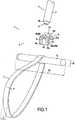
- the kit 1 for an implantable devicecomprises an example of an implantable device 2 and a gripping tool 3 comprising a bar 4 provided at its end 3a with a thread 5.
- the implantable device 2comprises a rod 6 having an outer radius Rt and a circumference Ct determined in a zone z along its length; a flat slender element 7 ; and a securing means 8 of said elongate member 7 in a partial wrapping position of said zone z .
- Said securing means 8comprises a first fork 9 and a second fork 10 having a first generally annular general shape of internal radius ri1 and ri2 respectively.
- Said first 9 and second 10 forkscomprise lower bearing surfaces 9a and 10a which are partially annular and respectively delimit first 9b and second 10b circumferential portions greater than half the circumference Ct.
- Said fastening means 8comprises a shoulder portion 11 having a second partially annular shape and coaxial with said first partially annular shape, said second form having an inner radius riep greater than the inner radii ri1 and ri2, respectively by a distance h1 and h2 so as to provide a passage for said elongate member 7 in said wrapping position between said forks 9 and 10 and said portion 11.
- the first 9 and second forks 10 and their inner rays ri1 and ri2are determined relative to the outer radius Rt of the rod 6 so that the force placement of the first 9 and second 10 forks of share and other of the elongate element 7 partially enveloping said rod 6, causes their deformation and their attachment to said rod 6.
- the first 9 and 10 second forkscomprise first 9c, 10c and 9d seconds , 10d ends, and the distance d1 between the first ends 9c, 10c on the one hand and the distance d2 between the second ends 9d, 10d on the other hand first 9 and second 10 forks are greater than or equal to the width I of the flat elongate element 7.
- the shoulder portion 11comprises a threaded hole 12 adapted to cooperate with the tool 3 provided with a corresponding threaded end 3a .
- first fork 9 and the second fork 10are in parallel planes p1 and p2 .
- the practitioner using the tool 3causes the threaded end 3a to cooperate with the tapped hole 12 formed in the shoulder portion 11 so as to force the first 9 and second 10 forks into the zone.
- z of the rod 6thus causing their deformation and their attachment to the rod 6.
- the forks 9,10 of the securing means 8are placed on either side of the elongated element 7, which is in a wrapping position of the rod 6. The securing means 8 thus prevents any transverse displacement of the elongated element 7 on the rod 6, ie any displacement along the longitudinal axis Lt.
- the heights h1 and h2are greater than the thickness e of the elongated element 7 so as to allow movements in rotation of the elongated element 7 around the rod 6.
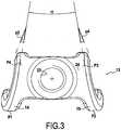
- the figure 3represents a variant 13 of the securing means 8 in which the first 14 and second 15 forks are in intersecting planes p3 and p4 forming an alpha angle less than or equal to 45 °, preferably less than or equal to 30 °.
- This provisionhas the advantage of stabilizing the securing means 13 when positioned on the rod 6 since it develops at least four support points which are not in alignment with each other, respectively points P1, P2 , P3 and P4.
- this arrangementprevents the elongated element 7 from overlapping the first 14 and second 15 forks when the elongate element 7 surrounds the rod 6 in a direction that is not substantially perpendicular to the axis Lt of the rod 6 .
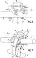
- the implantable device 2may also comprise an auxiliary holding means 16 for securing the securing means 13 secured to said zone z of said rod 6 as shown in FIGS. Figures 4 to 6 .
- the implantable device 2also includes a screw 17 having a threaded portion 17a and a shoulder 18.
- the auxiliary retaining means 16has the general shape of an inverted U having a base 19, having an auxiliary opening 20, which protrude transversely first 21 and second 22 branches provided at their ends 21a and 22a concave bearing areas 21b and 22b.
- the auxiliary means 16is arranged so that in operation the first 21 and second 22 branches are arranged on either side of the first 14 and second 15 forks, said auxiliary opening 20 being opposite the tapped hole 23, said concave zones 21b and 22b bearing against the length of said rod 6.
- the threaded portion 17a of the screw 17is then passed through the auxiliary opening 20 and engaged with said threaded hole 23 until the shoulder 18 comes into abutment against the shoulder portion 24, in particular against the tapped hole 23 projecting in this specific example of the shoulder portion 24.
- the threaded portion 17a of the screw 17it is possible to pinch or not the elongated element 7 passing between the forks 14 and 15.
- the height of the threaded portion 17a of the screw 17is determined so as not to pinch the elongated element 7 and allow it a possibility of rotational movement around the rod 6.
- the implantable device 2may also comprise, as shown in Figures 7 to 9 , a fastening loop device 25, as described in the application for EP Patent 2,555,698 A1 .
- this fastening buckle device 25thus comprises a rigid support 26 comprising two side portions 27 and 28 mounted between front portions 29 and back 30, the first end 7a of the elongate element 7 being secured or adapted to be secured at said rear portion 30 and the second end 7b of the elongated member 7 remaining free.
- the fixing loop device 25comprises a 31 locking element slidably mounted on said side portions 27 and 28 and defining passage front and rear zones respectively with the front 29 and back 30 allowing the passage of said second free end 7b in the rear passage zone and then the forward passage zone partially enclosing said locking element 31 so that the portion of said elongate element 7, extending substantially between its first end 7a and the locking element 31, forms a loop 32 given perimeter p and the application of opposing voltages on the inner walls of the loop 32 causes the displacement of said locking element 31 to said front portion 29 and the locking of the elongated element portion 7 in the forward passage zone between said locking element 31 and the front portion 29 of the support 26.
- the internal distance di separating the lateral portions 27 and 28is of the order of that of the main width I of said elongate element 7.
- the first 7a and second 7b ends of the elongate element 7are secured to each other by means of the fastening loop device 25.
- the elongate memberis in a partial wrapping position of the rod 6 and also passes around a portion of the vertebral body 33, in this specific example around a lamary apophysis.
- the elongated element 7has not been represented at figure 8 for reasons of simplification.
- the practitionervery easily adjusts the tensioning of the elongated element 7; it suffices to unlock the blocking element 31, then to exert traction on the second free end 7b of the elongate element 7; the elongated element 7 then slides around the rod 6, between the forks 14 and 15 and the shoulder portion 24, and without detaching the securing means 13. Then the practitioner again blocks the elongated element in rotation around of the rod 6, by means of the locking element 31 by sliding it towards the front part 29.
- the inner spokes of the first 9, 14 and second 10, 15 forksare arranged relative to the outer radius Rt of the rod 6 so that once the securing means 8, 13 clipped on the rod 6, it can not be move neither in rotation nor in translation along the longitudinal axis Lt of the rod 6.
- the inner radii of the first 9, 14 and second 10.15 forksare 0.7% lower relative to the outer radius Rt of the rod 6; preferably, said inner radii are 2.73 mm and the outer radius Rt is 2.75 mm.
- the width of the cross sections of the first ends 9c, 10c and 14c and 15c of the first 9, 14 and second 10, 15 forksis 1.50 mm
- the width of the cross sections of the second ends 9d, 10d and 14d, 15d of the first 9, 14 and second 10, 15 forksis 2.00 mm.
- the distance d1 between the first ends 9c and 10c on the one hand, and 14c and 15c on the other hand,is 10 mm.
- the distance d2 separating the second ends 9d and 10d on the one hand, and 14d and 15d on the other hand,is 15 mm.
- the securing means 8 or 16is made of titanium.
- the figure 10represents two implantable devices 2 according to the invention arranged on at least one vertebral level to be corrected.
- the two elongate elements 7are thus passed around portions of a vertebral body 34, in this specific example around the lamic apophyses.
- the implantable device 40 shown in FIG. figure 11 at least one vertebral level to be correctedcomprises a rod 41 having an outer radius Rt and a circumference Ct determined in a zone z along its length; a flat elongate member 42; and a securing means 50 of said elongated member 42 in a partial wrapping position of said zone z.
- Said securing means 50comprises a first fork 51 and a second fork 52 having a first generally annular general shape of internal radius ri1 and ri2 respectively .
- Said first 51 and second 52 forkscomprise lower bearing surfaces 51a and 52a partially annular respectively delimiting first 51b and second 52b circumferential portions greater than half the circumference Ct.
- Said securing means 50comprises a shoulder portion 60 arranged with respect to said lower bearing faces 51a, 52a of the first and second forks 51,52 so as to provide a passage for said elongate member 42 in said wrapping position between said forks ( 51,52 ) and said portion shoulder 60.
- said shoulder portion 60is recessed relative to said lower supporting faces 51a, 52a, respectively, a distance h1 and h2 so as to provide a passage for said elongated element 42.
- the first 51 and second 52 forks and their inner radii ri1 and ri2are determined relative to the outer radius Rt of the rod 42 so that the In force the first 51 and second 52 forks on either side of the elongate member 42 partially enveloping said rod 41, causes their deformation and then their attachment to said rod 41.
- the securing means 50comprises a part 70 having a bottom bearing surface 71 adapted to receive at least a portion of said elongate member 42 and clamping means 80 operable in translation and arranged with respect to said lower bearing face 71 so that the translational movement of said clamping means 80 allows the clamping of at least a portion of said elongate member 42 against said lower face of 71.
- the elongate element 42passes around at least a portion of a vertebral body and then its two free ends pass on the lower bearing surface 71 so that the two superimposed portions of said elongate element 42 are held together and clamped against said face lower support 71 by the clamping means 80.
- the shoulder portion 60space the first 51 and second 52 forks of a distance d3 greater than or equal to the width I1 of said flat elongate element 42 and greater than or equal to the diameter Dt of the rod 41 so that the forks 51,52 can rotate 90 ° when placed on the stem 41.
- the part 70comprises a tapped hole 72
- the clamping means 80comprise a screw 81 having a threaded portion 83 adapted to cooperate with said tapped hole 72 on the height H1.
- the clamping means 80further comprise a plate 84 and connecting means 85 ensuring the connection between said screw 81 and the plate 84 and arranged so that the rotation of said screw 81 causes the displacement in translation along the axis F of said plate 84 for clamping at least a portion of said elongate member 42 against the lower bearing face 71.
- the plate 84comprises a first face 84a and a second face 84b which are substantially flat and opposite.
- the screw 81comprises at its proximal end 81 has a housing 82 and at its distal end 81b an impression 87, in particular a polygonal impression, in particular with six lobes, adapted to cooperate with the complementary impression of a gripping tool for actuating the clamping means 80.
- the connecting means 85comprise at least one deformable portion 86 adapted to deform to be inserted into said housing 82 and then to cover its non-deformed shape to be secured to said housing 82.
- the connecting means 85comprise four portions. separate deformable 86 (only two of which are shown on section plane XIV-XIV) forming a deformable fir tail.
- the connection means 85are in this particular example secured to the plate 84, in particular to its first substantially planar face 84a .
- the piece 70has a parallelepipedal shape, in particular a rectangular parallelepiped shape, in particular a square shape, comprising lateral faces 70c, 70d, 70e, 70f, and upper faces 70a and lower 70b, in particular opposite sides, the said first 51 and second 52 forks projecting according to a first lateral face 70c selected from said side faces 70c, 70d, 70e, 70f of the workpiece 70.
- the shoulder portion 60is the upper face 70a of said workpiece 70.
- the workpiece 70 having an inner volume 73includes an intake port 74 and a outlet orifice 75 in its internal volume 73 of said elongate member 42 so as to form a passage opening at least on a clamping zone 76 delimited in part by said plate 84 and the lower bearing surface 71.
- the part 70comprises first attachment members 77 disposed in its lateral faces 70e and 70f, in particular two openings, in particular of oblong shape, only the opening formed in the lateral face 70e is shown in FIGS. figures 11 and 13 .
- the second openingis disposed in the side face 70f , opposite the side face 70e.
- the first attachment members 77are able to cooperate with second attachment members (not shown) of a gripping tool, said tool assisting in the placement of the securing means 50, and thus the forks 51, 52 on the rod. 41.
- the first 51 and second 52 forksare in opposition and in parallel planes p5, p6.
- the practitionerusing a tool provided with the second attachment members cooperating with the first attachment members 77 places in force the securing means 50 on the rod 41 by pivoting the first 51 and second fork 52 about 90 ° around the rod 41 thus causing their deformation and their attachment to the rod 41 on the z zone .
- the arrangement of the securing means 50can also be performed manually by the practitioner. In both cases, this operation causes the deformation of the forks 51,52 and their attachment to said rod 41. The practitioner then passes them.
- the practitioneractuates the clamping means 80 by means of a gripping tool (not shown) provided with a complementary cavity imprint 87 formed in the proximal portion 81b of the screw 81 for the rotation of the screw 81.
- the housing 82then abuts against the upper parts of said deformable portions 86 thus causing in translation along the axis F the plate 84 to bring it closer to the lower face of support 71 and thus tighten the superimposed portions of the elongated element 42.
- the opposing arrangement of the first and second forks 51, 52avoids any separation of said forks 51, 52 from the rod 41.
- the arrangement of at least a portion of the elongated element 42in this specific example of at least two portions of the elongated element 42 superimposed between the second substantially flat face 84b of the plate 84 and the lower bearing surface 71 , also substantially flat, allows a large contact surface with the elongate element 42 and thus a very large clamping force. For example, for a torque of 6N.m (newtons.meter) exerted on the screw 81 by means of a gripping tool, under the effect of a pull of 1067 newtons exerted on both ends free. of the elongated element 42 passed in the securing means 50, the elongated element 42 remains perfectly held between the plate 84 and the lower bearing surface 71.
- the forks 51,52 of the securing means 50are placed on either side of the elongated element 42, which is in a wrapping position of the rod 41.
- the securing means 50thus prevents any transverse displacement. of the elongated element 42 on the rod 41, ie any displacement along the longitudinal axis Lt.
Landscapes
- Health & Medical Sciences (AREA)
- Orthopedic Medicine & Surgery (AREA)
- Life Sciences & Earth Sciences (AREA)
- Neurology (AREA)
- Surgery (AREA)
- Heart & Thoracic Surgery (AREA)
- Engineering & Computer Science (AREA)
- Biomedical Technology (AREA)
- Nuclear Medicine, Radiotherapy & Molecular Imaging (AREA)
- Medical Informatics (AREA)
- Molecular Biology (AREA)
- Animal Behavior & Ethology (AREA)
- General Health & Medical Sciences (AREA)
- Public Health (AREA)
- Veterinary Medicine (AREA)
- Prostheses (AREA)
- Surgical Instruments (AREA)
Description
Translated fromFrenchLa présente invention concerne le domaine technique des dispositifs implantables, notamment pour corriger au moins un niveau vertébral, éventuellement avec fusion dudit niveau, lesdits dispositifs comprenant une tige, un élément longiligne plat et un moyen de solidarisation dudit élément longiligne à ladite tige.The present invention relates to the technical field of implantable devices, in particular for correcting at least one vertebral level, possibly with fusion of said level, said devices comprising a rod, a flat elongated element and a means for securing said elongate element to said rod.
Les tiges sont utilisées habituellement en combinaison avec un implant pour corriger au moins un niveau vertébral, tels qu'une vis et/ou un crochet recevant ladite tige.The rods are usually used in combination with an implant to correct at least one vertebral level, such as a screw and / or a hook receiving said rod.
De telles tiges peuvent être mises en oeuvre dans le traitement de la scoliose ou encore le traitement de pathologies dégénératives. On rencontre différents niveaux de dégénérescence, par exemple sur un niveau vertébral comme une discopathie ou sur deux niveaux vertébrales comme le spondylolisthésis ou encore plusieurs niveaux comme la scoliose en C ou en S.Such stems can be used in the treatment of scoliosis or the treatment of degenerative pathologies. There are different levels of degeneration, for example on a vertebral level such as discopathy or on two vertebral levels such as spondylolisthesis or several levels such as scoliosis in C or S.
Un exemple de dispositif de fixation vertébrale est décrit dans le document
Dans ces traitements, la tige peut être mise en liaison avec le niveau vertébral à corriger par l'intermédiaire d'un élément longiligne, lequel passe autour au moins d'une portion d'un corps vertébral et autour de ladite tige puis les extrémités dudit élément longiligne peuvent être maintenues au moyen d'une suture, d'un noeud ou à l'aide d'un moyen de solidarisation implantable. Ledit moyen de solidarisation peut par exemple comprendre un logement recevant la tige et l'élément longiligne à l'état enroulé autour de cette dernière, et des moyens de serrage pour le blocage de la tige et dudit élément longiligne dans ledit logement. Généralement, les moyens de serrage comprennent des moyens de pincement dudit élément longiligne empêchant tout mouvement de ce dernier.In these treatments, the rod can be connected to the vertebral level to be corrected by means of an elongated element, which passes around at least a portion of a vertebral body and around said rod and then the ends of said vertebral body. elongate member may be held by means of a suture, a node or using an implantable fastening means. Said securing means may for example comprise a housing receiving the rod and the elongated element in the wound state around the latter, and clamping means for locking the rod and said elongate member in said housing. Generally, the clamping means comprise means for clamping said elongate element preventing any movement of the latter.
Le pincement dudit élément longiligne a pour inconvénient qu'il peut engendrer une usure prématurée dudit élément longiligne par abrasion, ledit élément longiligne étant généralement dans un textile.The pinch of said elongate member has the disadvantage that it can cause premature wear of said elongated member by abrasion, said elongate member being generally in a textile.
Ces moyens de solidarisation ont également pour inconvénient qu'ils ne permettent pas l'ajustement de la mise en tension de l'élément longiligne, une fois le dispositif implantable posé sur le niveau vertébral à corriger car l'élément longiligne est totalement bloqué par les moyens de pincement. Or, il est souvent nécessaire d'ajuster la correction apportée par la tige, laquelle est en liaison avec l'élément longiligne, une fois le dispositif positionné sur le niveau vertébral à corriger.These securing means also have the disadvantage that they do not allow the adjustment of the tensioning of the elongated element, once the implantable device is placed on the vertebral level to be corrected because the elongated element is completely blocked by the pinching means. Now, it is often necessary to adjust the correction provided by the rod, which is in connection with the elongated element, once the device is positioned on the vertebral level to be corrected.
En outre ce type de moyen de solidarisation d'un élément longiligne à la tige n'est pas facilement réversible. Il est en effet très complexe de dévisser de multiples vis afin d'ajuster le réglage du niveau vertébral à traiter.In addition, this type of means for securing an elongated element to the rod is not easily reversible. It is indeed very complex to unscrew multiple screws in order to adjust the adjustment of the vertebral level to be treated.
Il existe ainsi un besoin pour un dispositif implantable, notamment pour corriger un niveau vertébral, comprenant un élément longiligne et un moyen de solidarisation dudit élément longiligne dans une position d'enveloppement de ladite tige, permettant audit élément longiligne d'être mise en tension autour de la tige une fois solidarisé dans ladite position d'enveloppement sans séparer le moyen de solidarisation de la tige déjà positionnée sur au moins un niveau vertébral à corriger.There is thus a need for an implantable device, in particular for correcting a vertebral level, comprising an elongate element and a means for securing said elongate element in a wrapping position of said rod, enabling said elongate element to be tensioned around of the rod once secured in said wrapping position without separating the securing means of the rod already positioned on at least one vertebral level to be corrected.
Il existe également un besoin pour un moyen de solidarisation, qui soit facile à mettre en place et à repositionner.There is also a need for a means of solidarity, which is easy to set up and reposition.
La présente invention propose un dispositif implantable selon la revendication indépendante 1. Des réalisations avantageuses de l'invention sont décrites dans les revendications dépendantes.The present invention provides an implantable device according to independent claim 1. Advantageous embodiments of the invention are described in the dependent claims.
La présente invention a ainsi pour objet, selon un premier aspect, un dispositif implantable, notamment pour corriger au moins un niveau vertébral, éventuellement avec fusion dudit niveau, comprenant :
- a. une tige ayant un rayon externe (Rt) et une circonférence (Ct) déterminées en une zone (z) sur sa longueur (Lt) ;
- b. un élément longiligne plat ; et
- c. un moyen de solidarisation dudit élément longiligne dans une position d'enveloppement partiel de ladite zone (z).
- at. a rod having an outer radius (Rt) and a circumference (Ct) determined in a zone (z) along its length (Lt );
- b. a slender flat element; and
- vs. means for securing said elongate element in a partial enveloping position of said zone (z).
Avantageusement, ledit moyen de solidarisation comprend une première fourche et une seconde fourche ayant une première forme générale partiellement annulaire de rayon interne respectivement ri1 et ri2. Lesdites première et seconde fourches comprennent des faces inférieures d'appui partiellement annulaires délimitant respectivement des première et seconde portions de circonférence supérieures à la moitié de la circonférence (Ct). Ledit moyen de solidarisation comprend une partie d'épaulement agencée par rapport auxdites faces inférieures d'appui des première et seconde fourches en sorte de ménager un passage pour ledit élément longiligne dans ladite position d'enveloppement entre lesdites fourches et ladite partie d'épaulement. Les première et seconde fourches et leurs rayons internes ri1 et ri2 sont déterminés par rapport au rayon externe Rt de la tige en sorte que le placement en force des première et seconde fourches de part et d'autre de l'élément longiligne enveloppant partiellement ladite tige, engendre leur déformation puis leur solidarisation à ladite tige.Advantageously, said securing means comprises a first fork and a second fork having a first generally annular general shape of internal radius respectively ri1 and ri2. Said first and second forks comprise partially annular bottom bearing faces respectively delimiting first and second portions of circumference greater than half the circumference (Ct). Said securing means comprises a shoulder portion arranged with respect to said bottom bearing faces of the first and second forks so as to provide a passage for said elongate member in said wrapping position between said forks and said shoulder portion. The first and second forks and their internal spokes ri1 and ri2 are determined relative to the outer radius Rt of the rod so that the force placement of the first and second forks on either side of the elongate member partially enveloping said rod , causes their deformation and their attachment to said rod.
Avantageusement, le moyen de solidarisation selon l'invention autorise l'élément longiligne à être mis en tension dans ladite position d'enveloppement puisque l'élément longiligne peut se mouvoir en rotation autour de la tige entre lesdites fourches et la partie d'épaulement. L'élément longiligne est simplement bloqué en translation selon l'axe longitudinal (Lt) de la tige entre lesdites fourches.Advantageously, the securing means according to the invention allows the elongated member to be tensioned in said wrapping position since the elongate member can move in rotation about the rod between said forks and the shoulder portion. The elongate element is simply locked in translation along the longitudinal axis (Lt) of the rod between said forks.
Le praticien peut ainsi ajuster la correction du niveau vertébral à traiter quand bien même le dispositif implantable selon l'invention est positionné sur au moins un niveau vertébral à corriger.The practitioner can thus adjust the correction of the vertebral level to be treated even though the implantable device according to the invention is positioned on at least one vertebral level to be corrected.
Avantageusement, le moyen de solidarisation comprend des première et seconde fourches déformables sous la pression exercée par la tige lors de son placement dans lesdites fourches, puis lesdites fourches se rétractent légèrement et se conforment au diamètre externe Dt de la tige tout en conservant une déformation (dite élastique).Advantageously, the securing means comprises first and second forks deformable under the pressure exerted by the rod during its placement in said forks, then said forks retract slightly and conform to the outer diameter Dt of the rod while maintaining a deformation ( called elastic).
Avantageusement, le moyen de solidarisation selon l'invention se solidarise en clipsant les fourches sur la tige en un emplacement déterminé disposé sur la longueur de celle-ci et qualifiée de zone (z). Le moyen de solidarisation se désolidarise très facilement en exerçant manuellement ou à l'aide d'un outil une traction visant à désengager les fourches de la tige, on obtient alors la déformation des fourches puis leur retrait dans leur position initiale correspondant aux rayons internes ri1 et ri2.Advantageously, the securing means according to the invention is secured by clipping the forks on the rod at a predetermined location disposed along the length thereof and described as zone (z). The securing means is very easily disengaged by manually exerting or with the aid of a tool a traction to disengage the forks of the rod, we then obtain the deformation of the forks and their removal in their initial position corresponding to the internal rays. and ri2.
En fonctionnement, l'élément longiligne exerçant une traction dans une direction qui est opposée à la direction selon laquelle la traction de désengagement doit être exercée, le moyen de solidarisation est parfaitement solidarisé à la tige. Cette dernière disposition est une sécurité supplémentaire pour le praticien, le dispositif implantable selon l'invention étant destiné à être implanté sur le rachis.In operation, the elongate member exerting a pull in a direction which is opposite to the direction in which the disengagement pull is to be exerted, the securing means is perfectly secured to the rod. This last provision is an additional safety for the practitioner, the implantable device according to the invention being intended to be implanted on the spine.
On comprend au sens de la présente invention par partie d'épaulement tout moyen de liaison assurant la liaison entre les première et seconde fourches et espaçant lesdites première et seconde fourches d'une distance supérieure ou égale à la largeur de l'élément longiligne plat, encore de préférence supérieure ou égale au diamètre externe Dt de la tige.Within the meaning of the present invention, it is understood by shoulder portion any connecting means providing the connection between the first and second forks and spacing said first and second forks by a distance greater than or equal to the width of the flat elongate member, still preferably greater than or equal to the outer diameter Dt of the rod.
En fonctionnement, le praticien dispose les première et seconde fourches de part et d'autre de l'élément longiligne disposé dans une position d'enveloppement autour de ladite tige dans une zone (z), en clipsant lesdites fourches sur la tige afin de les déformer pour qu'elles se solidarisent à la tige, leurs rayons internes étant ici supérieurs en fonctionnement ou égaux à celui du rayons externe Rt de la tige.In operation, the practitioner arranges the first and second forks on either side of the elongate element arranged in a wrapping position around said rod in an area (z), by clipping said forks onto the rod so as to to deform so that they are solidarize the rod, their inner radii here being greater in operation or equal to that of the outer rt Rt of the rod.
La déformabilité des première et secondes fourches et leur solidarisation sur ladite tige en sorte qu'il n'y ait ni translation, ni rotation desdites fourches sur la tige dépendent des paramètres suivants : largeur des sections transversales desdites fourches, le ou les matériaux constituant lesdites fourches, les rayons internes ri1 et ri2 déterminés par rapport au rayon externe Rt ; les première et secondes portions circonférentielles des faces inférieures d'appui annulaires déterminées par rapport à la circonférence Ct de la tige en sorte que lesdites fourches enveloppent suffisamment la tige.The deformability of the first and second forks and their attachment to said rod so that there is no translation or rotation of said forks on the rod depends on the following parameters: width of the cross sections of said forks, the material or materials constituting said forks, the internal radii ri1 and ri2 determined with respect to the outer radius Rt; the first and second circumferential portions of the annular lower bearing faces determined with respect to the circumference Ct of the rod so that said forks sufficiently envelop the rod.
L'homme du métier sait ainsi déterminer les largeurs des sections transversales des fourches et le ou les matériaux dans lesquelles elles sont fabriquées afin de leur attribuer une certaine déformabilité (en particulier rester dans une zone élastique de déformation lors de la contrainte exercée pour l'engagement de la tige dans le moyen de solidarisation) et une mémoire de leur forme initiale au repos, correspondant aux rayons internes ri1 et ri2.Those skilled in the art thus know how to determine the widths of the transverse sections of the forks and the material or materials in which they are manufactured in order to attribute to them a certain deformability (in particular to remain in an elastic zone of deformation during the stress exerted for the engagement of the rod in the securing means) and a memory of their initial form at rest, corresponding to the internal rays ri1 and ri2.
Les rayons internes ri1 et ri2 au repos desdites fourches sont déterminés par rapport au rayon externe Rt de la tige en sorte qu'une fois les fourches solidarisées à la tige, ces dernières ne peuvent se déplacer ni en translation ni en rotation sur la tige. De préférence, les rayons internes ri1 et ri2 au repos desdites fourches sont inférieurs ou égaux au rayon externe Rt de la tige, de préférence inférieurs de 3% ou égaux au rayon externe Rt de la tige, encore de préférence inférieurs de 1% ou égaux au rayon externe Rt de la tige, et encore de préférence inférieurs de 0,7% ou égaux au rayon externe de la tige.The internal ri1 and ri2 at rest of said forks are determined relative to the outer radius Rt of the rod so that once the forks secured to the rod, the latter can not move in translation or rotation on the rod. Preferably, the internal radii ri1 and ri2 at rest of said forks are less than or equal to the outer radius Rt of the rod, preferably less than 3% or equal to the outer radius Rt of the rod, more preferably less than 1% or equal at the outer radius Rt of the rod, and still preferably lower than 0.7% or equal to the outer radius of the rod.
L'élément longiligne selon l'invention est de préférence un élément textile, qui peut être tressée, tricotée ou tissée, de préférence tressée.The elongate member according to the invention is preferably a textile element, which can be braided, knitted or woven, preferably braided.
L'élément longiligne comprend des première et seconde extrémités.The elongate member includes first and second ends.
Le dispositif implantable selon l'invention peut également comprendre un dispositif à boucle de fixation tel que décrit dans la demande de
De préférence, le dispositif à boucle de fixation comprend un support rigide comprenant deux parties latérales montées entre des parties avant et arrière, ladite première extrémité étant solidarisée ou apte à être solidarisée à ladite partie arrière et ladite seconde extrémité restant libre.The implantable device according to the invention may also comprise a fastening loop device as described in the application for
Preferably, the fastening loop device comprises a rigid support comprising two lateral parts mounted between front and rear parts, said first end being secured or adapted to be secured to said rear portion and said second end remaining free.
Le dispositif à boucle de fixation comprend également un élément de blocage monté coulissant sur lesdites parties latérales et délimitant des zones de passage avant et arrière respectivement avec les parties avant et arrière permettant le passage de ladite seconde extrémité libre dans la zone de passage arrière puis la zone de passage avant en enveloppant partiellement ledit élément de blocage en sorte que la portion dudit élément longiligne s'étendant sensiblement entre sa première extrémité et l'élément de blocage forme une boucle de périmètre donné (p) et que l'application de tensions opposées sur les parois internes de la boucle provoque le déplacement dudit élément de blocage vers ladite partie avant et le blocage de la portion d'élément longiligne dans la zone de passage avant entre ledit élément de blocage et la partie avant du support.The fastening loop device also comprises a locking element slidably mounted on said lateral parts and delimiting front and rear passage zones respectively with the front and rear parts allowing the passage of said second free end in the rear passage zone and then the forward passage area by partially enclosing said locking member such that the portion of said elongate member extending substantially between its first end and the locking member forms a given perimeter loop (p) and that the application of opposing tensions on the inner walls of the loop causes the displacement of said locking member to said front portion and locking of the elongated member portion in the forward passage area between said locking member and the front portion of the support.
Il est également possible de solidariser les première et seconde extrémités de l'élément longiligne entre-elles par l'intermédiaire d'une suture, d'un noeud ou d'une bague métallique à écraser.It is also possible to secure the first and second ends of the elongated element together by means of a suture, a knot or a metal ring to be crushed.
De préférence, la distance interne (di) séparant les parties latérales est de l'ordre de celle de la largeur principale (I) dudit élément longiligne ou inférieure.Preferably, the internal distance (di) separating the lateral parts is of the order of that of the main width (I) of said elongate or lower element.
Le dispositif implantable selon l'invention peut être utilisé dans le traitement des scolioses ou encore dans le traitement de pathologies dégénératives, en particulier dans le traitement de différents niveaux de dégénérescence, par exemple sur un niveau vertébral comme une discopathie ou sur deux niveaux vertébrales comme le spondylolisthésis ou encore plusieurs niveaux comme la scoliose en C ou en S.The implantable device according to the invention can be used in the treatment of scoliosis or in the treatment of degenerative pathologies, in particular in the treatment of different levels of degeneration, for example on a vertebral level such as discopathy or on two vertebral levels such as spondylolisthesis or several levels such as scoliosis in C or S.
L'élément longiligne selon l'invention passe autour au moins d'une portion d'un corps vertébral, par exemple autour d'une apophyse lamaire ou lame vertébrale, ou encore d'une apophyse transversaire et/ou par croisement autour des deux apophyses.The elongate element according to the invention passes around at least a portion of a vertebral body, for example around a blade or vertebral apophysis, or a transverse process and / or by crossing around the two processes. .
Dans une variante ladite partie d'épaulement est en retrait par rapport auxdites faces inférieures d'appui, respectivement d'une distance h1 et h2 en sorte de ménager un passage pour ledit élément longiligne.In a variant, said shoulder portion is recessed with respect to said lower bearing faces, respectively a distance h1 and h2 so as to provide a passage for said elongate member.
Selon la hauteur h1 et h2, l'élément longiligne peut être plaqué ou non par la partie d'épaulement contre la tige, de préférence les hauteurs h1 et h2 sont supérieures à l'épaisseur (e) de l'élément longiligne en sorte de laisser une certaine liberté de mouvement audit élément longiligne en rotation autour de la tige.Depending on the height h1 and h2, the elongate member may or may not be plated by the shoulder portion against the rod, preferably the heights h1 and h2 are greater than the thickness (e) of the elongate member so that leave a certain freedom of movement to said elongate element in rotation around the rod.
La distance minimum séparant la première fourche de la seconde fourche, correspondant sensiblement à la largeur interne minimum de la partie d'épaulement, combinée aux hauteurs h1 et h2 telles que définies ci-dessus permet avantageusement de ménager un espace pour le passage d'un élément longiligne plat lorsque ledit moyen de solidarisation est solidarisé à la tige. En particulier, la distance séparant la première fourche de la seconde fourche est supérieure ou égale au diamètre externe Dt de la tige en sorte de laisser passer le diamètre de la tige lors de la disposition des première et seconde fourches sur la tige nécessitant un pivotement de 90° desdites fourches.The minimum distance separating the first fork from the second fork, corresponding substantially to the minimum internal width of the shoulder portion, combined with the heights h1 and h2 as defined above advantageously allows to provide a space for the passage of a flat slender element when said securing means is secured to the rod. In particular, the distance separating the first fork from the second fork is greater than or equal to the outer diameter Dt of the rod so as to allow the diameter of the rod to pass when the first and second forks are arranged on the rod requiring pivoting. 90 ° of said forks.
Dans une variante, le moyen de solidarisation comprend une pièce ayant une face inférieure d'appui apte à recevoir au moins une portion dudit élément longiligne et des moyens de serrage actionnables en translation et agencés par rapport à ladite face inférieure d'appui en sorte que le déplacement en translation desdits moyens de serrage permet le serrage d'au moins une portion dudit élément longiligne contre ladite face inférieure d'appui.In a variant, the securing means comprises a part having a bottom bearing face adapted to receive at least a portion of said elongate member and translationally actuatable clamping means arranged with respect to said lower bearing face so that translational movement of said clamping means allows the clamping of at least a portion of said elongate member against said lower bearing surface.
Avantageusement, l'élément longiligne n'est pas serré directement sur la tige mais sur une face inférieure d'appui, de préférence substantiellement plane, par l'intermédiaire des moyens de serrage. La zone de frottement entre l'élément longiligne plat et la face inférieure d'appui est avantageusement plus élevé que si l'élément longiligne avait été pincé ponctuellement de sorte que le serrage et donc la solidarisation d'une portion de l'élément longiligne contre ladite face inférieure est améliorée sans abraser et donc détériorer ladite portion d'élément longiligne.Advantageously, the elongated element is not clamped directly on the rod but on a lower bearing surface, preferably substantially flat, via the clamping means. The zone of friction between the flat elongate element and the lower bearing surface is advantageously greater than if the elongate element had been pinched punctually so that the clamping and thus the joining of a portion of the elongate element against said lower face is improved without abrading and thus deteriorating said elongated element portion.
Dans une sous-variante, ladite pièce comprend au moins une zone agencée en sorte de faire office de premiers organes d'attache apte à coopérer avec des seconds organes d'attache supportés par un outil de préhension, tel un ancillaire, ledit outil aidant au clipsage des fourches sur la tige.In a sub-variant, said part comprises at least one zone arranged so as to act as first fastening members adapted to cooperate with second fastening members supported by a gripping tool, such as an ancillary, said tool assisting the clipping of the forks on the rod.
Dans une variante, la partie d'épaulement espace la première fourche et la seconde fourche d'une distance supérieure ou égale à la largeur dudit élément longiligne plat, notamment supérieure ou égale au diamètre externe Dt de la tige.Alternatively, the shoulder portion spaced the first fork and the second fork a distance greater than or equal to the width of said flat elongated member, in particular greater than or equal to the outer diameter Dt of the rod.
Dans une variante, la pièce comprend un trou taraudé, et les moyens de serrage comprennent une vis ayant une portion filetée apte à coopérer avec ledit trou taraudé. Lesdits moyens de serrage comprennent en outre une plaque et des moyens de liaison assurant la liaison entre ladite vis et la plaque et agencés en sorte que la mise en rotation de ladite vis provoque le déplacement en translation de ladite plaque pour le serrage d'au moins une portion dudit élément longiligne plat contre la face inférieure d'appui.In a variant, the part comprises a tapped hole, and the clamping means comprise a screw having a threaded portion adapted to cooperate with said tapped hole. Said clamping means further comprise a plate and connecting means ensuring the connection between said screw and the plate and arranged so that the rotation of said screw causes the displacement in translation of said plate for clamping at least a portion of said elongated flat member against the lower bearing surface.
Avantageusement, deux portions dudit élément longiligne peuvent être serrées entre la plaque et la face inférieure d'appui. La plaque a une forme substantiellement plane de sorte que ladite au moins une portion dudit élément longiligne est serrée entre la face inférieure d'appui d'une part et la plaque d'autre part qui sont deux surfaces sensiblement planes offrant donc une surface de frottement importante. La surface de contact entre ladite au moins une portion dudit élément longiligne avec la face inférieure d'appui et la plaque étant améliorée, la force de serrage est augmentée. De plus, ladite au moins une portion dudit élément longiligne ne risque pas d'être détériorée par pincement. Un risque d'usure et donc de rupture prématuré dudit élément longiligne sont donc évités.Advantageously, two portions of said elongate element can be clamped between the plate and the lower bearing surface. The plate has a substantially planar shape so that said at least a portion of said elongate member is clamped between the lower bearing surface on the one hand and the plate on the other hand which are two substantially flat surfaces thus providing a friction surface important. The contact surface between said at least a portion of said elongate member with the lower bearing surface and the plate being improved, the clamping force is increased. In addition, said at least a portion of said elongate member is not likely to be damaged by pinching. A risk of wear and therefore premature failure of said elongate element are avoided.
De préférence, la vis comprend à son extrémité distale une empreinte apte à coopérer avec une empreinte complémentaire supportée par un outil de préhension pour sa mise en rotation, en particulier l'empreinte est de forme polygonale, notamment à six lobes.Preferably, the screw comprises at its distal end a fingerprint capable of cooperating with a complementary cavity supported by a gripping tool for its rotation, in particular the impression is of polygonal shape, in particular with six lobes.
Dans une variante, la vis comprend à son extrémité proximale un logement et les moyens de liaison comprennent au moins une portion déformable apte à se déformer pour être insérée dans ledit logement puis à recouvrir sa forme non déformée pour être solidarisée audit logement.In a variant, the screw comprises at its proximal end a housing and the connecting means comprise at least one deformable portion adapted to deform to be inserted into said housing and then to cover its undistorted shape to be secured to said housing.
Avantageusement, ladite au moins une portion déformable est déformée pour son introduction dans ledit logement. A l'état non déformée, ladite portion est solidarisée audit logement par blocage dans ce dernier, en particulier ladite portion vient en butée contre différentes régions du logement selon que la vis soit vissée ou dévissée dans ledit trou taraudé.Advantageously, said at least one deformable portion is deformed for its introduction into said housing. In the undeformed state, said portion is secured to said housing by locking in the latter, in particular said portion abuts against different regions of the housing according to whether the screw is screwed or unscrewed into said tapped hole.
Ainsi, lors de la mise en rotation de la vis et donc dudit logement, le logement tourne autour de ladite portion déformable et vient en butée contre cette dernière provoquant son déplacement en translation, et corrélativement le déplacement en translation de la plaque puisque les moyens de liaison et donc ladite au moins une portion déformable sont en liaison avec ladite plaque.Thus, during the rotation of the screw and thus of said housing, the housing rotates around said deformable portion and abuts against the latter causing its displacement in translation, and correlatively the displacement in translation of the plate since the means of link and thus said at least one deformable portion are in connection with said plate.
Dans une variante, ladite plaque comprend une première face et une seconde face sensiblement planes et opposées, ladite seconde face est orientée vers ladite face inférieure d'appui et ladite première face est orientée vers la vis.In a variant, said plate comprises a first face and a second substantially plane and opposite face, said second face is oriented towards said lower bearing face and said first face is oriented towards the screw.
Dans une variante, les moyens de liaison comprennent au moins deux portions déformables, encore de préférence au moins quatre portions déformables. En particulier, lesdites portions déformables forment une queue de sapin déformable.In a variant, the connecting means comprise at least two deformable portions, more preferably at least four deformable portions. In particular, said deformable portions form a deformable fir tail.
Dans une variante, les moyens de liaison sont solidarisés à ladite plaque.In a variant, the connecting means are secured to said plate.
Les moyens de liaison sont de préférence solidarisés à la première face de la plaque, notamment la queue de sapin déformable se projette de ladite première face en direction de la vis.The connecting means are preferably secured to the first face of the plate, in particular the deformable fir tail is projected from said first face in the direction of the screw.
Dans une variante, la pièce a une forme de parallélépipède, notamment de parallélépipède rectangle, comprenant des faces latérales, et des faces supérieure et inférieure, notamment opposées, lesdites première et seconde fourches se projetant selon une première face latérale choisie parmi lesdites faces latérales de la pièce.In a variant, the part has a parallelepipedal shape, in particular a rectangular parallelepiped shape, comprising lateral faces, and upper and lower faces, in particular opposite sides, said first and second forks projecting along a first lateral face chosen from said lateral faces of the room.
Dans une sous-variante, la pièce comprend une ouverture ménagée dans l'une de ses faces latérales faisant offices desdits premiers organes d'attache. De préférence, ladite ouverture a une forme oblongue. De préférence, ladite pièce comprend deux ouvertures, chacune desdites ouvertures étant ménagée dans une de ses faces latérales, lesdites deux faces latérales étant opposées.In a sub-variant, the part comprises an opening in one of its side faces making offices said first fasteners. Preferably, said opening has an oblong shape. Preferably, said part comprises two openings, each of said openings being formed in one of its lateral faces, said two lateral faces being opposite.
De préférence, ladite pièce a une forme de parallélépipède rectangle ou carré, en particulier de cube.Preferably, said piece has a rectangular or square parallelepiped shape, in particular of cube.
Dans une variante, la partie d'épaulement est la face supérieure de ladite pièce.In a variant, the shoulder portion is the upper face of said part.
Dans une variante, la pièce ayant un volume intérieur comprend un orifice d'admission et un orifice de sortie dans son volume intérieur dudit élément longiligne en sorte de former un passage débouchant au moins sur une zone de serrage délimitée en partie par ladite plaque et la face inférieure d'appui.In a variant, the part having an interior volume comprises an intake orifice and an outlet orifice in its interior volume of said elongate element so as to form a passage opening at least on a clamping zone delimited in part by said plate and the lower face of support.
Dans une variante, les première et seconde fourches sont en opposition.In a variant, the first and second forks are in opposition.
En particulier, les première et seconde fourches sont ouvertes l'une sur l'autre en sorte de tourner d'un angle de 90° lors de leur clipsage sur la tige.In particular, the first and second forks are open on one another so as to turn at an angle of 90 ° when clipping on the rod.
Cette disposition évite tout risque de désolidarisation prématurée des première et seconde fourches de la tige en fonctionnement puisque la force nécessaire à la désolidarisation de la première fourche de la tige s'effectue dans une direction qui est opposée à celle nécessaire pour désolidariser la seconde fourche de la tige.This arrangement avoids any risk of premature separation of the first and second forks of the operating rod since the force required to separate the first fork of the rod is in a direction which is opposite to that necessary to separate the second fork of the stem.
En outre, l'élément longiligne peut envelopper la tige selon une direction perpendiculaire ou non à la direction longitudinale de la tige ce qui offre davantage de possibilité au praticien dans la disposition de l'élément longiligne autour d'au moins une portion d'un corps vertébral.In addition, the elongate element can wrap the rod in a direction perpendicular or not to the longitudinal direction of the rod which offers more opportunity to the practitioner in the arrangement of the elongate element around at least a portion of a vertebral body.
Cette disposition permet ainsi d'éviter que l'élément longiligne ne monte sur l'une des fourches et reste bien positionné entre les deux fourches ou en butée contre l'une d'elles.This arrangement thus prevents the elongated element from rising on one of the forks and remains well positioned between the two forks or abutting against one of them.
Dans une variante de réalisation, les première et seconde fourches comprennent des premières et secondes extrémités, et la distance entre les premières extrémités d'une part et la distance entre les secondes extrémités d'autre part des première et seconde fourches sont supérieures ou égales à la largeur (I) du élément longiligne plat.In an alternative embodiment, the first and second forks comprise first and second ends, and the distance between the first ends on the one hand and the distance between the second ends on the other hand of the first and second forks are greater than or equal to the width (I) of the flat elongate element.
Dans une variante de réalisation, la partie d'épaulement comprend un trou taraudé apte à coopérer avec un outil pourvu d'une portion filetée correspondante.In an alternative embodiment, the shoulder portion comprises a threaded hole adapted to cooperate with a tool provided with a corresponding threaded portion.
Il est possible d'engager et de désengager le moyen de solidarisation sur la tige à l'aide dudit outil en liaison avec ledit trou taraudé.It is possible to engage and disengage the securing means on the rod with the aid of said tool in connection with said tapped hole.
Dans une variante de réalisation, les première et seconde fourches sont dans des plans parallèles.In an alternative embodiment, the first and second forks are in parallel planes.
Optionnellement, l'élément longiligne s'enveloppe ainsi autour de la tige en étant sensiblement perpendiculaire à la direction longitudinale (Lt) de la tige.Optionally, the elongate element thus wraps around the rod being substantially perpendicular to the longitudinal direction (Lt) of the rod.
Dans une variante de réalisation, les première et seconde fourches sont dans des plans sécants, de préférence formant un angle alpha inférieur ou égal à 45°, de préférence inférieur ou égal à 30°.In an alternative embodiment, the first and second forks are in secant planes, preferably forming an alpha angle less than or equal to 45 °, preferably less than or equal to 30 °.
Avantageusement, selon la largeur de la lame ou de l'apophyse lamaire, l'élément longiligne ne s'enroule pas dans une direction parfaitement perpendiculaire à la direction longitudinale (Lt) de la tige. En effet, l'élément longiligne peut arriver de côté sur la tige. Cette disposition permet ainsi d'éviter que l'élément longiligne ne monte sur l'une des fourches et reste bien positionné entre les deux fourches ou en butée contre l'une d'elles.Advantageously, depending on the width of the blade or the lamic apophysis, the elongated element does not roll up in a direction perfectly perpendicular to the direction longitudinal (Lt) of the stem. Indeed, the elongated element can arrive sideways on the rod. This arrangement thus prevents the elongated element from rising on one of the forks and remains well positioned between the two forks or abutting against one of them.
En outre, cette disposition permet de ménager deux points d'appui sur les branches avants des première et seconde fourches qui ne sont pas à l'aplomb des deux points d'appui ménagés au niveau des branches arrières desdites fourches, ce qui améliore la stabilité et le maintien du moyen de solidarisation sur la tige.In addition, this arrangement allows to provide two points of support on the front legs of the first and second forks that are not in line with the two support points formed at the rear branches of said forks, which improves the stability and maintaining the securing means on the rod.
Dans une variante de réalisation, le dispositif implantable selon l'invention comprend un moyen de maintien auxiliaire pour sécuriser le moyen de solidarisation solidarisé à ladite zone (z) de ladite tige.In an alternative embodiment, the implantable device according to the invention comprises an auxiliary holding means for securing the securing means secured to said zone (z) of said rod.
Cette disposition peut être nécessaire lorsque le praticien souhaite une sécurité supplémentaire visant à éviter tout risque de décoaptation du moyen de solidarisation de la tige.This provision may be necessary when the practitioner wishes additional safety to avoid any risk of decoaptation of the securing means of the rod.
Dans une sous-variante de réalisation, ledit dispositif comprend une vis ayant une portion filetée et ledit moyen de maintien auxiliaire a une forme générale en U inversé ayant une base, présentant une ouverture auxiliaire, de laquelle se projettent transversalement des première et seconde branches pourvues selon leurs extrémités de zones d'appui concaves, ledit moyen auxiliaire est agencé en sorte qu'en fonctionnement les première et seconde branches soient disposées de part et d'autre des première et seconde fourches, ladite ouverture auxiliaire étant au regard dudit trou taraudée, lesdites zones concaves d'appui venant en appui sur la longueur de ladite tige, ladite portion filetée étant passée à travers ladite ouverture et engagée avec ledit trou taraudé.In a sub-variant embodiment, said device comprises a screw having a threaded portion and said auxiliary holding means has a generally U-shaped inverted having a base, having an auxiliary opening, from which transversely project first and second branches provided. according to their ends concave bearing areas, said auxiliary means is arranged so that in operation the first and second branches are arranged on either side of the first and second forks, said auxiliary opening being opposite said threaded hole, said concave bearing areas abutting the length of said rod, said threaded portion being passed through said opening and engaged with said tapped hole.
Le moyen de maintien auxiliaire exerce ainsi une pression sur la partie d'épaulement du moyen de solidarisation par l'intermédiaire de sa base, pression qui s'exerce de manière opposée à la direction selon laquelle peut être exercée la pression de désengagement du moyen de solidarisation.The auxiliary holding means thus exerts pressure on the shoulder portion of the securing means via its base, which pressure is exerted opposite the direction in which the disengagement pressure can be exerted joining.
La pression exercée par le moyen de maintien auxiliaire se répartie ainsi sur sa base et sur les zones d'appui concaves venant en appui sur la tige de part et d'autre des première et seconde fourches.The pressure exerted by the auxiliary holding means is distributed thus on its base and on the concave bearing areas bearing on the rod on either side of the first and second forks.
De préférence, les zones d'appui concaves viennent en appui sur la tige dans une zone dans laquelle les première et seconde fourches ne recouvrent pas la tige.Preferably, the concave bearing areas bear on the rod in an area in which the first and second forks do not cover the rod.
Dans une variante de réalisation, la vis comprend un épaulement venant en fonctionnement en butée contre la base dudit moyen de maintien auxiliaire.In an alternative embodiment, the screw comprises a shoulder coming into operation in abutment against the base of said auxiliary holding means.
Avantageusement, selon les hauteurs de la portion filetée et de l'épaulement de la vis, il est possible de comprimer ou non l'élément longiligne par l'intermédiaire de l'extrémité libre de la vis. De préférence, les hauteurs de la portion filetée et de l'épaulement sont déterminées en sorte de ne pas comprimer l'élément longiligne et éviter tout risque de dégradation par piqure et abrasion.Advantageously, depending on the heights of the threaded portion and the shoulder of the screw, it is possible to compress or not the elongated element by means of the free end of the screw. Preferably, the heights of the threaded portion and the shoulder are determined so as not to compress the elongate member and avoid any risk of degradation by stitching and abrasion.
Eventuellement, l'extrémité libre de la vis peut être agencée par rapport à la vis en sorte de ne pas être entraînée en rotation lors du vissage de la vis dans le trou taraudé ménagé dans la partie d'épaulement du moyen de solidarisation. Cette disposition permet ainsi d'exercer simplement une pression sur l'élément longiligne sans rotation sur ce dernier, ce qui limite le risque de détériorer ledit élément longiligne.Optionally, the free end of the screw may be arranged relative to the screw so as not to be rotated during screwing of the screw in the threaded hole formed in the shoulder portion of the securing means. This arrangement thus makes it possible to simply exert a pressure on the elongated element without rotation on the latter, which limits the risk of damaging said elongate element.
De préférence, l'extrémité libre de la vis est plate.Preferably, the free end of the screw is flat.
L'ouverture auxiliaire du moyen de maintien auxiliaire peut être éventuellement taraudée afin de coopérer avec la portion filetée de la vis. Dans ce cas, la portion filetée est séparée de l'épaulement par une rainure, la rainure étant en retrait par rapport à l'épaulement et à la portion filetée. Cette disposition permet d'engager le moyen de maintien auxiliaire avec la vis, le moyen de maintien auxiliaire étant bloqué au niveau de la rainure entre l'épaulement et la portion filetée. En fonctionnement, le praticien visse ainsi la portion filetée de la vis dans le trou taraudé de la partie d'épaulement du moyen de solidarisation sans entrainer en rotation le moyen de maintien auxiliaire.The auxiliary opening of the auxiliary holding means may be optionally threaded to cooperate with the threaded portion of the screw. In this case, the threaded portion is separated from the shoulder by a groove, the groove being recessed with respect to the shoulder and the threaded portion. This arrangement makes it possible to engage the auxiliary holding means with the screw, the auxiliary holding means being locked at the groove between the shoulder and the threaded portion. In operation, the practitioner thus screws the threaded portion of the screw in the tapped hole of the shoulder portion of the securing means without rotating the auxiliary holding means.
Dans une variante de réalisation, les première et seconde branches dudit moyen de maintien auxiliaire sont dans des plans sécants formant un angle beta, de préférence l'angle béta est inférieur ou égal à 30°, de préférence égal à alpha.In an alternative embodiment, the first and second branches of said auxiliary holding means are in intersecting planes forming a beta angle, preferably the beta angle is less than or equal to 30 °, preferably equal to alpha.
Les première et seconde branches pourraient être également dans des plans sensiblement parallèles, en particulier si les première et seconde fourches sont également dans des plans sensiblement parallèles.The first and second branches could also be in substantially parallel planes, particularly if the first and second forks are also in substantially parallel planes.
Dans une variante de réalisation, ledit moyen de solidarisation, et éventuellement le moyen de maintien auxiliaire, est dans un ou plusieurs matériaux sélectionné(s) dans la liste comprenant : le titane, l'acier inoxydable, un alliage de titane et de nickel, du polyétheréthercétone (PEEK), PEK (polyéthercétone), chrome cobalt, polyamide 6-6, polyamide 6, polytéréphtalate d'éthylène, et notamment tout autre matériau dit biocompatible à plus de 30 jours.In an alternative embodiment, said securing means, and possibly the auxiliary holding means, is in one or more materials selected from the list comprising: titanium, stainless steel, an alloy of titanium and nickel, polyetheretherketone (PEEK), PEK (polyetherketone), chromium cobalt, polyamide 6-6,
La présente invention a pour objet selon un deuxième aspect, un kit pour dispositif implantable comprenant un dispositif implantable selon l'une quelconque des variantes de réalisation précédentes, et un outil de préhension dudit moyen de solidarisation comprenant une barre pourvue à son extrémité de premiers organes de fixation aptes à coopérer avec des seconds organes de fixation supportés par ledit moyen de solidarisation.The subject of the present invention is, according to a second aspect, a kit for an implantable device comprising an implantable device according to any one of the preceding embodiments, and a tool for gripping said securing means comprising a bar provided at its end with first organs. fasteners adapted to cooperate with second fastening members supported by said securing means.
Dans une sous-variante, les premiers organes de fixation sont un filetage et les seconds organes de fixation sont un trou taraudé ménagé dans la partie d'épaulement ou que comprend la pièce selon l'invention, et éventuellement un taraudage ménagé dans l'ouverture auxiliaire de la base du moyen de maintien auxiliaire.In a sub-variant, the first fasteners are a thread and the second fasteners are a threaded hole formed in the shoulder portion or that comprises the piece according to the invention, and possibly a tapped hole in the opening auxiliary base of the auxiliary holding means.
Selon une alternative, lesdits seconds organes d'attache sont une ou deux ouvertures ménagées dans une ou deux faces latérales de la pièce décrite ci-dessus.According to an alternative, said second attachment members are one or two openings in one or both side faces of the part described above.
La présente invention sera mieux comprise à la lecture d'un exemple de réalisation de kit pour dispositif implantable selon l'invention, et d'un second exemple de dispositif implantable selon l'invention cités à titre non limitatif, et illustrés par les figures suivantes dans lesquelles :
- la
figure1 est une vue en perspective représentant de manière schématique un exemple de kit selon l'invention comprenant un exemple de dispositif implantable selon l'invention ; - la
figure2 est une représentation schématique et en perspective du moyen de solidarisation utilisé dans le dispositif implantable représenté à lafigure1 ; - la
figure3 est une représentation schématique et en perspective d'une variante du moyen de solidarisation représenté à lafigure2 ; - la
figure4 est une représentation schématique et en perspective d'un moyen de maintien auxiliaire en combinaison avec le dispositif représenté à lafigure1 et comprenant le moyen de solidarisation représenté à lafigure3 ; - la
figure5 est une représentation schématique et en perspective du moyen de maintien auxiliaire représenté à lafigure4 ; - la
figure6 est une représentation schématique et en perspective de l'exemple de dispositif implantable selon l'invention comprenant le moyen de solidarisation représenté à lafigure3 , une vis et le moyen de maintien auxiliaire représenté auxfigures4 ;et 5 - la
figure7 est une représentation schématique et en perspective selon une vue antérieure de l'exemple de dispositif implantable représenté à lafigure6 dans laquelle le dispositif comprend en outre un dispositif à boucle de fixation pour la solidarisation du élément longiligne sur lui-même dans ladite position d'enveloppement, le dispositif implantable selon l'invention est représenté dans une position dans laquelle l'élément longiligne passe autour au moins d'une portion d'un corps vertébral, dans cet exemple précis autour d'une apophyse lamaire; - la
figure8 est une représentation schématique et en perspective selon une vue postérieure du dispositif représenté à lafigure7 ; - la
figure9 est une représentation schématique et vue de côté, avec des parties arrachées du dispositif représenté auxfigures7 et8 ; et - la
figure10 est une représentation schématique selon une vue postérieure, dans laquelle deux dispositifs implantables selon l'invention tels que ceux représentés en référence auxfigures6 à9 , sont positionnés sur au moins un niveau vertébral à corriger. - la
figure11 est une représentation schématique et en perspective d'un second exemple de dispositif implantable selon l'invention positionné sur au moins un niveau vertébral à corriger ; - la
figure12 est une représentation schématique et vue de côté des moyens de solidarisation du second exemple de dispositif implantable représenté à lafigure11 ; - la
figure13 est une représentation schématique et vue de dessus des moyens de solidarisation du second exemple de dispositif implantable représenté à lafigure11 ; - la
figure14 est une représentation schématique des moyens de solidarisation représentés auxfigures11 à13 selon le plan de coupe XIV-XIV représenté à lafigure13 .
- the
figure1 is a perspective view schematically showing an exemplary kit according to the invention comprising an example of an implantable device according to the invention; - the
figure2 is a diagrammatic representation in perspective of the securing means used in the implantable device shown in FIG.figure1 ; - the
figure3 is a schematic representation in perspective of a variant of the securing means shown in FIG.figure2 ; - the
figure4 is a diagrammatic and perspective representation of an auxiliary holding means in combination with the device shown in FIG.figure1 and comprising the securing means shown in FIG.figure3 ; - the
figure5 is a diagrammatic representation in perspective of the auxiliary holding means shown in FIG.figure4 ; - the
figure6 is a schematic representation in perspective of the example of implantable device according to the invention comprising the securing means shown in FIG.figure3 , a screw and the auxiliary holding means shown inFigures4 and5 ; - the
figure7 is a diagrammatic representation in perspective according to an anterior view of the example of an implantable device represented in FIG.figure6 wherein the device further comprises a fastening loop device for securing the elongate member to itself in said wrapping position, the implantable device according to the invention is shown in a position in which the elongate member passes around at least a portion of a vertebral body, in this specific example around a lamary apophysis; - the
figure8 is a schematic representation in perspective according to a posterior view of the device represented in FIG.figure7 ; - the
figure9 is a schematic and side view, with broken parts of the device shown infigures7 and8 ; and - the
figure10 is a schematic representation in a posterior view, in which two implantable devices according to the invention such as those shown with reference toFigures6 to9 , Are positioned on at least one vertebral level to be corrected. - the
figure11 is a diagrammatic representation in perspective of a second example of implantable device according to the invention positioned on at least one vertebral level to be corrected; - the
figure12 is a schematic representation and side view of the securing means of the second example of implantable device shown in FIG.figure11 ; - the
figure13 is a schematic representation and view from above of the securing means of the second example of an implantable device represented in FIG.figure11 ; - the
figure14 is a schematic representation of the securing means represented inFigures11 to13 according to section plane XIV-XIV shown infigure13 .
Le kit1 pour dispositif implantable comprend un exemple de dispositif implantable2 et un outil de préhension3 comprenant une barre4 pourvue à son extrémité3a d'un filetage5.The kit1 for an implantable device comprises an example of an
Le dispositif implantable2 comprend une tige6 ayant un rayon externeRt et une circonférenceCt déterminées en une zonez sur sa longueur ; un élément longiligne plat7 ; et un moyen de solidarisation8 dudit élément longiligne7 dans une position d'enveloppement partiel de ladite zonez. Ledit moyen de solidarisation8 comprend une première fourche9 et une seconde fourche10 ayant une première forme générale partiellement annulaire de rayon interne respectivementri1 etri2. Lesdites première9 et seconde10 fourches comprennent des faces inférieures d'appui9a et10a partiellement annulaires délimitant respectivement des première9b et seconde10b portions de circonférence supérieures à la moitié de la circonférenceCt. Ledit moyen de solidarisation8 comprend une partie d'épaulement11 ayant une seconde forme partiellement annulaire et coaxiale avec ladite première forme partiellement annulaire, ladite seconde forme ayant un rayon interne riep supérieure aux rayons internesri1 etri2, respectivement d'une distanceh1 eth2 en sorte de ménager un passage pour ledit élément longiligne7 dans ladite position d'enveloppement entre lesdites fourches9 et10 et ladite partie d'épaulement11. Les première9 et seconde10 fourches et leurs rayons internesri1 etri2 sont déterminés par rapport au rayon externeRt de la tige6 en sorte que le placement en force des première9 et seconde10 fourches de part et d'autre de l'élément longiligne7 enveloppant partiellement ladite tige6, engendre leur déformation puis leur solidarisation à ladite tige6.The
Il est également possible de placer le moyen de solidarisation8 manuellement sur la tige6 sans l'aide de l'outil de préhension3.It is also possible to place the securing means8 manually on the
Les première9 et10 seconde fourches comprennent des premières9c, 10c et secondes9d, 10d extrémités, et la distanced1 entre les premières extrémités9c, 10c d'une part et la distanced2 entre les secondes extrémités9d, 10d d'autre part des première9 et seconde10 fourches sont supérieures ou égales à la largeurI de l'élément longiligne plat7.The first9 and10 second forks comprise first9c, 10c and9d seconds, 10d ends, and the distanced1 between the first ends9c, 10c on the one hand and the distanced2 between the second ends9d, 10d on the other hand first9 and second10 forks are greater than or equal to the widthI of the flat
La partie d'épaulement11 comprend un trou taraudé12 apte à coopérer avec l'outil3 pourvu d'une extrémité filetée3a correspondante.The
Dans cet exemple précis, la première fourche9 et la seconde fourche10 sont dans des plansp1 etp2 parallèles.In this specific example, the
En fonctionnement, le praticien à l'aide de l'outil3 fait coopérer l'extrémité3a filetée avec le trou taraudé12 ménagé dans la partie d'épaulement11 en sorte de placer en force les première9 et seconde10 fourches sur la zonez de la tige6 engendrant ainsi leur déformation puis leur solidarisation sur la tige6. Les fourches9,10 du moyen de solidarisation8 sont placées de part et d'autre de l'élément longiligne7, lequel est dans une position d'enveloppement de la tige6. Le moyen de solidarisation8 empêche ainsi tout déplacement transversale de l'élément longiligne7 sur la tige6, i.e tout déplacement selon l'axe longitudinaleLt.In operation, the practitioner using the tool3 causes the threaded
Il est également possible de positionner le moyen de solidarisation8 sans l'aide de l'outil3, simplement manuellement.It is also possible to position the securing means8 without the aid of the tool3, simply manually.
Dans cet exemple précis, les hauteursh1 eth2 sont supérieures à l'épaisseure de l'élément longiligne7 en sorte d'autoriser des mouvements en rotation de l'élément longiligne7 autour de la tige6.In this specific example, the heightsh1 andh2 are greater than the thicknesse of the
La
Le dispositif implantable2 peut comprendre également un moyen de maintien auxiliaire16 pour sécuriser le moyen de solidarisation13 solidarisé à ladite zonez de ladite tige6 tel que représenté aux
Le dispositif implantable2 comprend également une vis17 ayant une portion filetée17a et un épaulement18. Le moyen de maintien auxiliaire16 a une forme générale en U inversé ayant une base19, présentant une ouverture auxiliaire20, de laquelle se projettent transversalement des première21 et seconde22 branches pourvues selon leurs extrémités21a et22a de zones d'appui concaves21b et22b. Le moyen auxiliaire16 est agencé en sorte qu'en fonctionnement les première21 et seconde22 branches soient disposées de part et d'autre des première14 et seconde15 fourches, ladite ouverture auxiliaire20 étant au regard du trou taraudé23, lesdites zones concaves d'appui21b et22b venant en appui sur la longueur de ladite tige6. La portion filetée17a de la vis17 est alors passée à travers l'ouverture auxiliaire20 et engagée avec ledit trou taraudé23 jusqu'à ce que l'épaulement18 vienne en butée contre la partie d'épaulement24, en particulier contre le trou taraudé23 se projetant dans cet exemple précis de la partie d'épaulement24. Selon la hauteur de la portion filetée17a de la vis17, il est possible de pincer ou non l'élément longiligne7 passant entre les fourches14 et15.The
De préférence, la hauteur de la portion filetée17a de la vis17 est déterminée en sorte de ne pas pincer l'élément longiligne7 et lui laisser une possibilité de mouvement en rotation autour de la tige6.Preferably, the height of the threaded
Le dispositif implantable2 peut également comprendre, tel que représenté aux
De préférence, ce dispositif à boucle de fixation25 comprend ainsi un support rigide26 comprenant deux parties latérales27 et28 montées entre des parties avant29 et arrière30, la première extrémité7a de l'élément longiligne7 étant solidarisée ou apte à être solidarisée à ladite partie arrière30 et la seconde extrémité7b de l'élément longiligne7 restant libre.Preferably, this
Le dispositif à boucle de fixation25 comprend un élément de blocage31 monté coulissant sur lesdites parties latérales27 et28 et délimitant des zones de passage avant et arrière respectivement avec les parties avant29 et arrière30 permettant le passage de ladite seconde extrémité libre7b dans la zone de passage arrière puis la zone de passage avant en enveloppant partiellement ledit élément de blocage31 en sorte que la portion dudit élément longiligne7, s'étendant sensiblement entre sa première extrémité7a et l'élément de blocage31, forme une boucle32 de périmètre donnép et l'application de tensions opposées sur les parois internes de la boucle32 provoque le déplacement dudit élément de blocage31 vers ladite partie avant29 et le blocage de la portion d'élément longiligne7 dans la zone de passage avant entre ledit élément de blocage31 et la partie avant29 du support26.The fixing
De préférence, la distance interne di séparant les parties latérales27 et28 est de l'ordre de celle de la largeur principaleI dudit élément longiligne7.Preferably, the internal distance di separating the
Les première7a et seconde7b extrémités de l'élément longiligne7 sont solidarisées entre-elles grâce au dispositif à boucle de fixation25.The first7a and second7b ends of the
Sur les
En fonctionnement, le praticien ajuste très facilement la mise en tension de l'élément longiligne7 ; il lui suffit de débloquer l'élément de blocage31, puis d'exercer une traction sur la seconde extrémité libre7b de l'élément longiligne7 ; l'élément longiligne7 coulisse alors autour de la tige6, entre les fourches14 et15 et la partie d'épaulement24, et ce sans désolidariser le moyen de solidarisation13. Puis le praticien bloque à nouveau l'élément longiligne en rotation autour de la tige6, par l'intermédiaire de l'élément de blocage31 en le faisant coulisser vers la partie avant29.In operation, the practitioner very easily adjusts the tensioning of the
Les rayons internes des première9, 14 et seconde10, 15 fourches sont agencés par rapport au rayon externeRt de la tige6 en sorte qu'une fois le moyen de solidarisation8, 13 clipsé sur la tige6, ce dernier ne puisse se déplacer ni en rotation, ni en translation selon l'axe longitudinalLt de la tige6.The inner spokes of the first9, 14 and second10, 15 forks are arranged relative to the outer radiusRt of the
Dans cet exemple précis, Les rayons internes des première9, 14 et seconde10,15 fourches sont inférieurs de 0,7% par rapport au rayon externeRt de la tige6 ; de préférence, lesdits rayons internes sont de 2,73 mm et le rayon externeRt est de 2,75 mm.In this specific example, the inner radii of the first9, 14 and second10.15 forks are 0.7% lower relative to the outer radiusRt of the
Dans cet exemple précis, la largeur des sections transversales des premières extrémités9c, 10c et14c et15c des premières9, 14 et secondes10, 15 fourches est de 1,50 mm, et la largeur des sections transversales des secondes extrémités9d, 10d et14d, 15d des premières9, 14 et secondes10, 15 fourches est de 2,00 mm.In this specific example, the width of the cross sections of the first ends9c, 10c and14c and15c of the first9, 14 and second10, 15 forks is 1.50 mm, and the width of the cross sections of the second ends9d, 10d and14d, 15d of the first9, 14 and second10, 15 forks is 2.00 mm.
La distanced1 séparant les premières extrémités9c et10c d'une part, et14c et15c d'autre part, est de 10 mm. La distanced2 séparant les secondes extrémités9d et10d d'une part, et14d et15d d'autre part, est de 15 mm.The distanced1 between the first ends9c and10c on the one hand, and14c and15c on the other hand, is 10 mm. The distanced2 separating the second ends9d and10d on the one hand, and14d and15d on the other hand, is 15 mm.
De préférence, le moyen de solidarisation8 ou16 est en titane.Preferably, the securing means8 or16 is made of titanium.
La
Les deux éléments longilignes7 sont ainsi passés autour de portions d'un corps vertébral34, dans cet exemple précis autour des apophyses lamaires.The two
Le dispositif implantable40 représenté à la
Le moyen de solidarisation50 comprend une pièce70 ayant une face inférieure d'appui71 apte à recevoir au moins une portion dudit élément longiligne42 et des moyens de serrage80 actionnables en translation et agencés par rapport à ladite face inférieure d'appui71 en sorte que le déplacement en translation desdits moyens de serrage80 permet le serrage d'au moins une portion dudit élément longiligne42 contre ladite face inférieure d'appui71. Tel que cela est visible à la
La partie d'épaulement60 espace les première51 et seconde52 fourches d'une distanced3 supérieure ou égale à la largeurI1 dudit élément longiligne plat42 et supérieure ou égale au diamètre Dt de la tige41 afin que les fourches51,52 puissent pivoter de 90° lors de leur placement sur la tige41.The
La pièce70 comprend un trou taraudé72, et les moyens de serrage80 comprennent une vis81 ayant une portion filetée83 apte à coopérer avec ledit trou taraudé72 sur la hauteurH1. Les moyens de serrage80 comprennent en outre une plaque84 et des moyens de liaison85 assurant la liaison entre ladite vis81 et la plaque84 et agencés en sorte que la mise en rotation de ladite vis81 provoque le déplacement en translation selon l'axeF de ladite plaque84 pour le serrage d'au moins une portion dudit élément longiligne42 contre la face inférieure d'appui71. La plaque84 comprend une première face84a et une seconde face84b qui sont sensiblement planes et opposées. La vis81 comprend à son extrémité proximale81a un logement82 et à son extrémité distale81b une empreinte87, notamment une empreinte polygonale, en particulier à six lobes, apte à coopérer avec l'empreinte complémentaire d'un outil de préhension pour actionner les moyens de serrage80.The
Les moyens de liaison85 comprennent au moins une portion déformable86 apte à se déformer pour être insérée dans ledit logement82 puis à recouvrir sa forme non déformée pour être solidarisée audit logement82. Dans cet exemple précis, les moyens de liaison85 comprennent quatre portions déformables distinctes86 (dont seulement deux sont représentées sur le plan de coupe XIV-XIV) formant une queue de sapin déformable. Les moyens de liaison85 sont dans cet exemple précis solidarisés à la plaque84, en particulier à sa première face84a sensiblement plane.The connecting means85 comprise at least one
La pièce70 a dans cet exemple précis une forme de parallélépipède, notamment de parallélépipède rectangle, en particulier carré, comprenant des faces latérales (70c, 70d, 70e, 70f), et des faces supérieure70a et inférieure70b, notamment opposées, lesdites première51 et seconde52 fourches se projetant selon une première face latérale70c choisie parmi lesdites faces latérales70c, 70d, 70e, 70f de la pièce70. La partie d'épaulement60 est la face supérieure70a de ladite pièce70. La pièce70 ayant un volume intérieur73 comprend un orifice d'admission74 et un orifice de sortie75 dans son volume intérieur73 dudit élément longiligne42 en sorte de former un passage débouchant au moins sur une zone de serrage76 délimitée en partie par ladite plaque84 et la face inférieure d'appui71.In this example, the
La pièce70 comprend des premiers organes d'attache77 disposés dans ses faces latérales70e et70f, en particulier deux ouvertures, notamment de forme oblongue, seule l'ouverture ménagée dans la face latérale70e est représentée aux
Les première51 et seconde52 fourches sont en opposition et dans des plans parallèlesp5, p6.The first51 and second52 forks are in opposition and in parallel planesp5, p6.
En fonctionnement, une fois l'élément longiligne42 placé autour d'au moins une portion d'un corps vertébral et autour au moins partiellement de la tige41, le praticien à l'aide d'un outil pourvu des seconds organes d'attache coopérant avec les premiers organes d'attache77 place en force les moyens de solidarisation50 sur la tige41 en faisant pivoter les première51 et seconde fourche52 d'environ 90° autour de la tige41 engendrant ainsi leur déformation puis leur solidarisation à la tige41 sur la zonez. La disposition des moyens de solidarisation50 peut être effectuée également manuellement par le praticien. Dans les deux cas, cette opération provoque la déformation des fourches51,52 puis leur solidarisation sur ladite tige41. Le praticien passe ensuite les. extrémités libres de l'élément longiligne plat42 dans la zone de serrage76 à travers l'orifice d'entrée74 et l'orifice de sortie75 et exerce une tension manuellement ou une tension à l'aide d'un outil approprié sur les extrémités libres de l'élément longiligne42. Enfin, le praticien actionne les moyens de serrage80 par l'intermédiaire d'un outil de préhension (non représenté) pourvu d'une empreinte complémentaire de l'empreinte87 ménagée dans la partie proximale81b de la vis81 pour la mise en rotation de la vis81. Le logement82 vient alors en butée contre les parties supérieures desdites portions déformables86 entrainant ainsi en translation selon l'axeF la plaque84 pour la rapprocher de la face inférieure d'appui71 et ainsi serrer les portions superposées de l'élément longiligne42.In operation, once the
Avantageusement, la disposition en opposition des première et seconde fourches51,52 évite toute désolidarisation desdites fourches51,52 de la tige41. En outre, la disposition d'au moins une portion de l'élément longiligne42, dans cet exemple précis d'au moins deux portions de l'élément longiligne42 superposées entre la seconde face sensiblement plane84b de la plaque84 et la face inférieure d'appui71, également sensiblement plane, permet une surface de contact importante avec l'élément longiligne42 et ainsi une force de serrage très importante. A titre d'exemple, pour un couple de 6N.m (newtons.mètre) exercé sur la vis81 par l'intermédiaire d'un outil de préhension, sous l'effet d'une traction de 1067 newtons exercée sur les deux extrémités libres. de l'élément longiligne42 passé dans les moyens de solidarisation50, l'élément longiligne42 reste parfaitement maintenu entre la plaque84 et la face inférieure d'appui71.Advantageously, the opposing arrangement of the first and
Enfin, les fourches51,52 du moyen de solidarisation50 sont placées de part et d'autre de l'élément longiligne42, lequel est dans une position d'enveloppement de la tige41. Le moyen de solidarisation50 empêche ainsi tout déplacement transversale de l'élément longiligne42 sur la tige41, i.e tout déplacement selon l'axe longitudinaleLt.Finally, the
Claims (14)
- An implantable device (2, 40), in particular to correct at least one vertebral level, optionally with fusion of said level, comprising:a. a rod (6, 41) having an outer radius (Rt) and a circumference (Ct) determined at an area (z) along its length (Lt);b. a flat elongate element (7, 42);c. a device (8, 13, 50) to secure said elongate element (7, 42) in a position partly encasing said area (z);characterized in that said securing device (8, 13, 50) comprises a first fork (9, 14, 51) and a second fork (10, 15, 52) having a first general partly annular shape of inner radius ri1 and ri2 respectively,in that said first (9, 14, 51) and second forks (10, 15, 52) comprise partly annular lower bearing surfaces (9a, 10a, 51a, 52a) respectively delimiting first (9b, 51b) and second (10b, 52b) portions of circumference greater than one half of the circumference (Ct),in that said securing device (8, 13, 50) comprises a shoulder part (11, 24, 60) arranged relative to said lower bearing surfaces (9a, 10a, 51a, 52a) of the first and second forks (9, 14, 51, 10, 15, 52) so as to form a passage for said elongate element in said encasing position between said forks and said shoulder part, andin that the first (9, 14, 51) and second (10, 15, 52) forks and their inner radii ri1 and ri2 are determined in relation to the outer radius Rt of the rod (6, 41) so that the press-fitting of the first (9, 14, 51) and second (10, 15, 52) forks either side of the elongate element (7, 42) partly encasing said rod (6, 7) causes deformation thereof and then their securing to said rod (6, 7).
- The implantable device (2, 40) according to claim 1,characterized in that said shoulder part (11, 24, 60) is recessed relative to said lower bearing surfaces (9a, 10a, 51a, 52a), by a distance hi and h2 respectively so as to form a passage for said elongate element (7, 42).
- The implantable device (40) according to either of claims 1 and 2,characterized in that the securing device (50) comprises a piece (70) having a lower bearing surface (71) capable of receiving at least one portion of said elongate element (42), and clamping device (80) which can be actuated in translation and arranged relative to said lower bearing surface (71) so that the movement in translation of said clamping device (80) allows the clamping of at least one portion of said elongate element (42) against said lower bearing surface (71).
- The implantable device (2, 40) according to any one of claims 1 to 3,characterized in that the shoulder part (11, 24, 60) spaces apart the first fork (9, 14, 51) and the second fork (10, 15, 52) by a distance (d1, d2, d3) equal to or greater than the width (I, I1) of said flat elongate element (7, 42).
- The implantable device (40) according to either of claims 3 and 4,characterized in that the piece (70) comprises a tapped hole (72), and the clamping device (80) comprise a screw (81) having a threaded portion (83) able to cooperate with said tapped hole (72), andin that said clamping device (80) further comprises a plate (84) and connecting device (85) ensuring a link between said screw (81) and the plate (84) and arranged so that the setting in rotation of said screw (81) causes the movement in translation of said plate (84) to clamp at least one portion of said elongate element (42) against the lower bearing surface (71).
- The implantable device (40) according to claim 5,characterized in that the screw (81) at its proximal end (81a) comprises a housing (82) andin that the connecting device (85) comprises at least one deformable portion (86) able to be deformed so that it can be inserted in said housing (82) and to recover its non-deformed shape for securing to said housing (82).
- The implantable device (40) according to either of claims 5 and 6,characterized in that the connecting device (85) is secured to said plate (84).
- The implantable device (40) according to any one of claims 3 to 7,characterized in that the piece (70) is of parallelepiped shape, in particular rectangular parallelepiped shape comprising side surfaces (70c, 70d, 70e, 70f), and particularly opposite-lying upper (70a) and lower (70b) surfaces, said first (51) and second (52) forks projecting along a first side surface (70c) selected from among said side surfaces (70c, 70f) of the piece (70).
- The implantable device (40) according to claim 8,characterized in that the shoulder part (60) is the upper surface (70a) of said piece (70).
- The implantable device (40) according to any one of claims 3 to 9,characterized in that the piece (70) having an inner volume (73) comprises an inlet orifice (74) and an outlet orifice (75) in its inner volume (73) for said elongate element (42) so as to form a passage opening onto at least one clamping area (76) partly delimited by said plate (84) and the lower bearing surface (71).
- The implantable device (40) according to any one of claims 1 to 10,characterized in that the first (51) and second (52) forks are in opposition.
- The implantable device (2, 40) according to any one of claims 1 to 11,characterized in that the first (9, 51) and second (10, 52) forks lie in parallel planes (pi, p2, p5, p6).
- The implantable device (2, 40) according to any one of claims 1 to 12,characterized in that said securing device (8, 13, 50) is in one or more materials selected from the list comprising: titanium, stainless steel, a titanium and nickel alloy, polyetheretherketone (PEEK), PEK (polyetherketone), chromium cobalt, polyamide 6-6, polyamide 6, ethylene polyterephthalate.
- A kit (1) for implantable device comprising an implantable device (2, 40) according to any one of claims 1 to 13, and a grasping tool (3) for said securing device (8, 13, 40) comprising a bar (4) provided at its end (3a) with first attaching members (5) able to cooperate with second attaching members (12, 23) supported by said securing device (8, 13, 40).
Applications Claiming Priority (2)
| Application Number | Priority Date | Filing Date | Title |
|---|---|---|---|
| FR1356963AFR3008305B1 (en) | 2013-07-15 | 2013-07-15 | IMPLANTABLE DEVICE, IN PARTICULAR FOR CORRECTING AT LEAST ONE VERTEBRAL LEVEL |
| PCT/FR2014/051801WO2015007985A1 (en) | 2013-07-15 | 2014-07-11 | Implantable device, in particular for correcting at least one vertebral level |
Publications (2)
| Publication Number | Publication Date |
|---|---|
| EP3021770A1 EP3021770A1 (en) | 2016-05-25 |
| EP3021770B1true EP3021770B1 (en) | 2017-01-25 |
Family
ID=49212932
Family Applications (1)
| Application Number | Title | Priority Date | Filing Date |
|---|---|---|---|
| EP14747095.9ANot-in-forceEP3021770B1 (en) | 2013-07-15 | 2014-07-11 | Implantable device, in particular for correcting at least one vertebral level |
Country Status (7)
| Country | Link |
|---|---|
| US (1) | US10433878B2 (en) |
| EP (1) | EP3021770B1 (en) |
| JP (1) | JP6442497B2 (en) |
| AU (1) | AU2014291889B2 (en) |
| ES (1) | ES2618548T3 (en) |
| FR (1) | FR3008305B1 (en) |
| WO (1) | WO2015007985A1 (en) |
Families Citing this family (11)
| Publication number | Priority date | Publication date | Assignee | Title |
|---|---|---|---|---|
| FR3026636B1 (en) | 2014-10-01 | 2017-09-15 | Cousin Biotech | ANCHORAGE FOR TENSIONING A LONGILINE ELEMENT FOR ATTACHING AN IMPLANT TO A BONE MEMBER |
| WO2016172677A1 (en)* | 2015-04-24 | 2016-10-27 | K2M, Inc. | Tethering screw system |
| FR3035584B1 (en)* | 2015-04-29 | 2017-05-19 | Medicrea Int | MATERIAL OF VERTEBRAL OSTEOSYNTHESIS |
| US10307186B2 (en)* | 2016-12-02 | 2019-06-04 | Nuvasive, Inc. | Surgical band clamp system |
| US10463403B2 (en) | 2017-07-31 | 2019-11-05 | Medos International Sarl | Systems and methods for reducing the risk of proximal junctional kyphosis using a bone anchor or other attachment point |
| US10456174B2 (en) | 2017-07-31 | 2019-10-29 | Medos International Sarl | Connectors for use in systems and methods for reducing the risk of proximal junctional kyphosis |
| US11051857B2 (en) | 2017-08-10 | 2021-07-06 | Ortho Development Corporation | Tether clamping assemblies and related methods and apparatus |
| US11071569B2 (en)* | 2017-08-10 | 2021-07-27 | Ortho Development Corporation | Nesting tether clamping assemblies and related methods and apparatus |
| CN108542483B (en)* | 2018-04-20 | 2024-01-02 | 昆明医科大学第二附属医院 | Spinal column orthopedic device capable of protecting growth potential of organism |
| FR3097114B1 (en)* | 2019-06-13 | 2024-05-31 | Medicrea Int | Additional fixation device for a pedicle screw on a spinal bone segment |
| US11819255B2 (en) | 2019-10-07 | 2023-11-21 | Ortho Development Corporation | Tether tensioning instrumentation and related methods |
Family Cites Families (25)
| Publication number | Priority date | Publication date | Assignee | Title |
|---|---|---|---|---|
| US5601552A (en)* | 1994-03-18 | 1997-02-11 | Sofamor, S.N.C. | Fixing device for a rigid transverse connection device between rods of a spinal osteosynthesis system |
| US5800548A (en)* | 1996-03-05 | 1998-09-01 | Bruno Franck | Device for transverse spinal connection |
| FR2750033B1 (en)* | 1996-06-20 | 1998-09-11 | Euros Sa | DEVICE FOR CROSS-CONNECTION OF RODS OF IMPLANTS |
| US6783526B1 (en)* | 1997-05-15 | 2004-08-31 | Howmedica Osteonics Corp. | Transverse rod connector clip |
| FR2829014B1 (en)* | 2001-09-03 | 2005-04-08 | Stryker Spine | SPINAL OSTEOSYNTHESIS SYSTEM COMPRISING A SUPPORT SKATE |
| EP1364622B1 (en)* | 2002-05-21 | 2005-07-20 | Spinelab GmbH | Elastical system for stabilising the spine |
| US7066938B2 (en)* | 2002-09-09 | 2006-06-27 | Depuy Spine, Inc. | Snap-on spinal rod connector |
| CN1856277A (en)* | 2003-07-03 | 2006-11-01 | 新特斯有限责任公司 | Top loading spinal fixation device and instruments for loading and handling the same |
| US7833248B2 (en)* | 2006-03-10 | 2010-11-16 | Custom Spine, Inc. | Spinal cross-connector |
| WO2008008853A2 (en)* | 2006-07-11 | 2008-01-17 | Pioneer Surgical Technology, Inc. | Transverse connector |
| EP2047813A1 (en)* | 2007-10-11 | 2009-04-15 | Abbott Spine | Bone fixing system and method of use |
| FR2918555B1 (en)* | 2007-07-12 | 2010-04-02 | Ldr Medical | DEVICE AND SYSTEM FOR TRANSVERSE SPINACH CONNECTION |
| WO2010081029A1 (en) | 2009-01-08 | 2010-07-15 | Rotation Medical, Inc. | Implantable tendon protection systems and related kits and methods |
| EP2279707A1 (en)* | 2009-07-31 | 2011-02-02 | Zimmer Spine | Bone fixing system |
| FR2954905B1 (en)* | 2010-01-06 | 2012-12-28 | Implanet | DEVICE FOR FIXING VERTEBRAL |
| FR2961687B1 (en) | 2010-06-23 | 2015-05-22 | Cousin Biotech | LONGILINE ELEMENT RETENTION DEVICE SUITABLE FOR MAINTAINING DETERMINED INTERVERTEBRAL CLEARANCE |
| EP2734135B1 (en)* | 2011-07-21 | 2018-03-21 | Zimmer Spine | Spinal rod fixing device |
| US8740950B2 (en)* | 2011-12-08 | 2014-06-03 | Spine Wave, Inc. | Methods for percutaneously attaching a cross connector to contralateral spinal constructs |
| FR2985165B1 (en)* | 2011-12-29 | 2014-01-17 | Cousin Biotech | DEVICE FOR FIXING VERTEBRAL |
| US8945188B2 (en)* | 2012-04-06 | 2015-02-03 | William Alan Rezach | Spinal correction system and method |
| US10548644B2 (en)* | 2013-03-05 | 2020-02-04 | Globus Medical, Inc. | Elastic member clamps |
| US9433441B2 (en)* | 2013-03-05 | 2016-09-06 | Globus Medical, Inc. | Elastic member clamps |
| US9675386B2 (en)* | 2013-03-11 | 2017-06-13 | K2M, Inc. | Flexible fastening system |
| US20160183985A1 (en)* | 2013-07-31 | 2016-06-30 | Spinal Usa, Inc. | Spinal stabilization cam-locking cross-connector |
| US20170086889A1 (en)* | 2015-09-24 | 2017-03-30 | Warsaw Orthopedic, Inc. | Spinal implant system and method |
- 2013
- 2013-07-15FRFR1356963Apatent/FR3008305B1/ennot_activeExpired - Fee Related
- 2014
- 2014-07-11EPEP14747095.9Apatent/EP3021770B1/ennot_activeNot-in-force
- 2014-07-11USUS14/904,987patent/US10433878B2/enactiveActive
- 2014-07-11AUAU2014291889Apatent/AU2014291889B2/ennot_activeCeased
- 2014-07-11WOPCT/FR2014/051801patent/WO2015007985A1/enactiveApplication Filing
- 2014-07-11ESES14747095.9Tpatent/ES2618548T3/enactiveActive
- 2014-07-11JPJP2016526675Apatent/JP6442497B2/ennot_activeExpired - Fee Related
Non-Patent Citations (1)
| Title |
|---|
| None* |
Also Published As
| Publication number | Publication date |
|---|---|
| JP2016526997A (en) | 2016-09-08 |
| US10433878B2 (en) | 2019-10-08 |
| ES2618548T3 (en) | 2017-06-21 |
| US20160249957A1 (en) | 2016-09-01 |
| FR3008305B1 (en) | 2015-08-07 |
| JP6442497B2 (en) | 2018-12-19 |
| AU2014291889A1 (en) | 2016-02-11 |
| WO2015007985A1 (en) | 2015-01-22 |
| AU2014291889B2 (en) | 2019-04-04 |
| FR3008305A1 (en) | 2015-01-16 |
| EP3021770A1 (en) | 2016-05-25 |
Similar Documents
| Publication | Publication Date | Title |
|---|---|---|
| EP3021770B1 (en) | Implantable device, in particular for correcting at least one vertebral level | |
| EP2521500B1 (en) | Vertebral attachment device | |
| EP1926444B2 (en) | Vertebral fixing systemw | |
| EP2648635B1 (en) | Device for tensioning a flexible band | |
| EP2725993B1 (en) | Vertebral fixation device | |
| EP1933743B1 (en) | Accessory for tensioning a flexible link | |
| EP2770925B1 (en) | Device for tensioning a flexible strip and assembly comprising such a device wtih flexible strip | |
| EP3119298B1 (en) | Surgical assembly, and bone anchor screw and device for extending one such screw that belong to said surgical assembly | |
| FR2761876A1 (en) | INSTRUMENTATION OF LUMBAR OSTEOSYNTHESIS FOR CORRECTION OF SPONDYLOLISTHESIS BY POSTERIOR PATHWAY | |
| FR2780269A1 (en) | Spinal implant for use with linking rod to treat fractures and correct deformities | |
| FR2807313A1 (en) | Device for maintaining the soft tissues during surgery of the vertebral column comprises valves acting on the incision edges mounted on a ring made of two half-rings connected by pins | |
| EP2862529B1 (en) | Vertebral fixation device and system and method for blocking a loop with such a device | |
| EP3200710B1 (en) | Accessory for tensioning an elongate element | |
| FR2974725A1 (en) | ORTHODONTIC APPARATUS WITH SLIDING RODS | |
| WO2018202839A1 (en) | Accessory for tensioning an elongate element | |
| EP3082630B1 (en) | Vertebral fixation device with double fastening, system for blocking a loop with such a device | |
| EP3565491B1 (en) | Bone screw for osteosynthesis device, assembly formed by a screw, a connector and a nut, and kit comprising at least one such assembly | |
| EP3518818A1 (en) | Jaw plate, kit and method for installing same | |
| FR2890849A1 (en) | Vertebral fixing system for e.g. scoliosis treatment, has connection part defining through path for elongated flexible link such that portions of link are engaged with path for defining link part and free ends |
Legal Events
| Date | Code | Title | Description |
|---|---|---|---|
| PUAI | Public reference made under article 153(3) epc to a published international application that has entered the european phase | Free format text:ORIGINAL CODE: 0009012 | |
| 17P | Request for examination filed | Effective date:20160106 | |
| AK | Designated contracting states | Kind code of ref document:A1 Designated state(s):AL AT BE BG CH CY CZ DE DK EE ES FI FR GB GR HR HU IE IS IT LI LT LU LV MC MK MT NL NO PL PT RO RS SE SI SK SM TR | |
| AX | Request for extension of the european patent | Extension state:BA ME | |
| DAX | Request for extension of the european patent (deleted) | ||
| GRAP | Despatch of communication of intention to grant a patent | Free format text:ORIGINAL CODE: EPIDOSNIGR1 | |
| INTG | Intention to grant announced | Effective date:20161028 | |
| GRAS | Grant fee paid | Free format text:ORIGINAL CODE: EPIDOSNIGR3 | |
| GRAA | (expected) grant | Free format text:ORIGINAL CODE: 0009210 | |
| AK | Designated contracting states | Kind code of ref document:B1 Designated state(s):AL AT BE BG CH CY CZ DE DK EE ES FI FR GB GR HR HU IE IS IT LI LT LU LV MC MK MT NL NO PL PT RO RS SE SI SK SM TR | |
| REG | Reference to a national code | Ref country code:GB Ref legal event code:FG4D Free format text:NOT ENGLISH | |
| REG | Reference to a national code | Ref country code:CH Ref legal event code:EP | |
| REG | Reference to a national code | Ref country code:AT Ref legal event code:REF Ref document number:863654 Country of ref document:AT Kind code of ref document:T Effective date:20170215 | |
| REG | Reference to a national code | Ref country code:IE Ref legal event code:FG4D Free format text:LANGUAGE OF EP DOCUMENT: FRENCH | |
| REG | Reference to a national code | Ref country code:DE Ref legal event code:R096 Ref document number:602014006408 Country of ref document:DE | |
| REG | Reference to a national code | Ref country code:CH Ref legal event code:NV Representative=s name:P&TS SA, CH | |
| REG | Reference to a national code | Ref country code:LT Ref legal event code:MG4D | |
| REG | Reference to a national code | Ref country code:NL Ref legal event code:MP Effective date:20170125 | |
| REG | Reference to a national code | Ref country code:AT Ref legal event code:MK05 Ref document number:863654 Country of ref document:AT Kind code of ref document:T Effective date:20170125 | |
| REG | Reference to a national code | Ref country code:ES Ref legal event code:FG2A Ref document number:2618548 Country of ref document:ES Kind code of ref document:T3 Effective date:20170621 | |
| REG | Reference to a national code | Ref country code:FR Ref legal event code:PLFP Year of fee payment:4 | |
| PG25 | Lapsed in a contracting state [announced via postgrant information from national office to epo] | Ref country code:NL Free format text:LAPSE BECAUSE OF FAILURE TO SUBMIT A TRANSLATION OF THE DESCRIPTION OR TO PAY THE FEE WITHIN THE PRESCRIBED TIME-LIMIT Effective date:20170125 | |
| PG25 | Lapsed in a contracting state [announced via postgrant information from national office to epo] | Ref country code:GR Free format text:LAPSE BECAUSE OF FAILURE TO SUBMIT A TRANSLATION OF THE DESCRIPTION OR TO PAY THE FEE WITHIN THE PRESCRIBED TIME-LIMIT Effective date:20170426 Ref country code:LT Free format text:LAPSE BECAUSE OF FAILURE TO SUBMIT A TRANSLATION OF THE DESCRIPTION OR TO PAY THE FEE WITHIN THE PRESCRIBED TIME-LIMIT Effective date:20170125 Ref country code:NO Free format text:LAPSE BECAUSE OF FAILURE TO SUBMIT A TRANSLATION OF THE DESCRIPTION OR TO PAY THE FEE WITHIN THE PRESCRIBED TIME-LIMIT Effective date:20170425 Ref country code:IS Free format text:LAPSE BECAUSE OF FAILURE TO SUBMIT A TRANSLATION OF THE DESCRIPTION OR TO PAY THE FEE WITHIN THE PRESCRIBED TIME-LIMIT Effective date:20170525 Ref country code:FI Free format text:LAPSE BECAUSE OF FAILURE TO SUBMIT A TRANSLATION OF THE DESCRIPTION OR TO PAY THE FEE WITHIN THE PRESCRIBED TIME-LIMIT Effective date:20170125 Ref country code:HR Free format text:LAPSE BECAUSE OF FAILURE TO SUBMIT A TRANSLATION OF THE DESCRIPTION OR TO PAY THE FEE WITHIN THE PRESCRIBED TIME-LIMIT Effective date:20170125 | |
| PG25 | Lapsed in a contracting state [announced via postgrant information from national office to epo] | Ref country code:PL Free format text:LAPSE BECAUSE OF FAILURE TO SUBMIT A TRANSLATION OF THE DESCRIPTION OR TO PAY THE FEE WITHIN THE PRESCRIBED TIME-LIMIT Effective date:20170125 Ref country code:PT Free format text:LAPSE BECAUSE OF FAILURE TO SUBMIT A TRANSLATION OF THE DESCRIPTION OR TO PAY THE FEE WITHIN THE PRESCRIBED TIME-LIMIT Effective date:20170525 Ref country code:RS Free format text:LAPSE BECAUSE OF FAILURE TO SUBMIT A TRANSLATION OF THE DESCRIPTION OR TO PAY THE FEE WITHIN THE PRESCRIBED TIME-LIMIT Effective date:20170125 Ref country code:SE Free format text:LAPSE BECAUSE OF FAILURE TO SUBMIT A TRANSLATION OF THE DESCRIPTION OR TO PAY THE FEE WITHIN THE PRESCRIBED TIME-LIMIT Effective date:20170125 Ref country code:BG Free format text:LAPSE BECAUSE OF FAILURE TO SUBMIT A TRANSLATION OF THE DESCRIPTION OR TO PAY THE FEE WITHIN THE PRESCRIBED TIME-LIMIT Effective date:20170425 Ref country code:LV Free format text:LAPSE BECAUSE OF FAILURE TO SUBMIT A TRANSLATION OF THE DESCRIPTION OR TO PAY THE FEE WITHIN THE PRESCRIBED TIME-LIMIT Effective date:20170125 Ref country code:AT Free format text:LAPSE BECAUSE OF FAILURE TO SUBMIT A TRANSLATION OF THE DESCRIPTION OR TO PAY THE FEE WITHIN THE PRESCRIBED TIME-LIMIT Effective date:20170125 | |
| REG | Reference to a national code | Ref country code:DE Ref legal event code:R097 Ref document number:602014006408 Country of ref document:DE | |
| PG25 | Lapsed in a contracting state [announced via postgrant information from national office to epo] | Ref country code:EE Free format text:LAPSE BECAUSE OF FAILURE TO SUBMIT A TRANSLATION OF THE DESCRIPTION OR TO PAY THE FEE WITHIN THE PRESCRIBED TIME-LIMIT Effective date:20170125 Ref country code:RO Free format text:LAPSE BECAUSE OF FAILURE TO SUBMIT A TRANSLATION OF THE DESCRIPTION OR TO PAY THE FEE WITHIN THE PRESCRIBED TIME-LIMIT Effective date:20170125 Ref country code:CZ Free format text:LAPSE BECAUSE OF FAILURE TO SUBMIT A TRANSLATION OF THE DESCRIPTION OR TO PAY THE FEE WITHIN THE PRESCRIBED TIME-LIMIT Effective date:20170125 Ref country code:SK Free format text:LAPSE BECAUSE OF FAILURE TO SUBMIT A TRANSLATION OF THE DESCRIPTION OR TO PAY THE FEE WITHIN THE PRESCRIBED TIME-LIMIT Effective date:20170125 | |
| PG25 | Lapsed in a contracting state [announced via postgrant information from national office to epo] | Ref country code:DK Free format text:LAPSE BECAUSE OF FAILURE TO SUBMIT A TRANSLATION OF THE DESCRIPTION OR TO PAY THE FEE WITHIN THE PRESCRIBED TIME-LIMIT Effective date:20170125 Ref country code:SM Free format text:LAPSE BECAUSE OF FAILURE TO SUBMIT A TRANSLATION OF THE DESCRIPTION OR TO PAY THE FEE WITHIN THE PRESCRIBED TIME-LIMIT Effective date:20170125 | |
| PLBE | No opposition filed within time limit | Free format text:ORIGINAL CODE: 0009261 | |
| STAA | Information on the status of an ep patent application or granted ep patent | Free format text:STATUS: NO OPPOSITION FILED WITHIN TIME LIMIT | |
| 26N | No opposition filed | Effective date:20171026 | |
| PG25 | Lapsed in a contracting state [announced via postgrant information from national office to epo] | Ref country code:SI Free format text:LAPSE BECAUSE OF FAILURE TO SUBMIT A TRANSLATION OF THE DESCRIPTION OR TO PAY THE FEE WITHIN THE PRESCRIBED TIME-LIMIT Effective date:20170125 | |
| REG | Reference to a national code | Ref country code:IE Ref legal event code:MM4A | |
| PG25 | Lapsed in a contracting state [announced via postgrant information from national office to epo] | Ref country code:IE Free format text:LAPSE BECAUSE OF NON-PAYMENT OF DUE FEES Effective date:20170711 | |
| REG | Reference to a national code | Ref country code:BE Ref legal event code:MM Effective date:20170731 | |
| PG25 | Lapsed in a contracting state [announced via postgrant information from national office to epo] | Ref country code:LU Free format text:LAPSE BECAUSE OF NON-PAYMENT OF DUE FEES Effective date:20170711 | |
| REG | Reference to a national code | Ref country code:FR Ref legal event code:PLFP Year of fee payment:5 | |
| PG25 | Lapsed in a contracting state [announced via postgrant information from national office to epo] | Ref country code:BE Free format text:LAPSE BECAUSE OF NON-PAYMENT OF DUE FEES Effective date:20170731 | |
| PG25 | Lapsed in a contracting state [announced via postgrant information from national office to epo] | Ref country code:MT Free format text:LAPSE BECAUSE OF FAILURE TO SUBMIT A TRANSLATION OF THE DESCRIPTION OR TO PAY THE FEE WITHIN THE PRESCRIBED TIME-LIMIT Effective date:20170125 | |
| PG25 | Lapsed in a contracting state [announced via postgrant information from national office to epo] | Ref country code:HU Free format text:LAPSE BECAUSE OF FAILURE TO SUBMIT A TRANSLATION OF THE DESCRIPTION OR TO PAY THE FEE WITHIN THE PRESCRIBED TIME-LIMIT; INVALID AB INITIO Effective date:20140711 Ref country code:MC Free format text:LAPSE BECAUSE OF FAILURE TO SUBMIT A TRANSLATION OF THE DESCRIPTION OR TO PAY THE FEE WITHIN THE PRESCRIBED TIME-LIMIT Effective date:20170125 | |
| PG25 | Lapsed in a contracting state [announced via postgrant information from national office to epo] | Ref country code:CY Free format text:LAPSE BECAUSE OF FAILURE TO SUBMIT A TRANSLATION OF THE DESCRIPTION OR TO PAY THE FEE WITHIN THE PRESCRIBED TIME-LIMIT Effective date:20170125 | |
| PG25 | Lapsed in a contracting state [announced via postgrant information from national office to epo] | Ref country code:MK Free format text:LAPSE BECAUSE OF FAILURE TO SUBMIT A TRANSLATION OF THE DESCRIPTION OR TO PAY THE FEE WITHIN THE PRESCRIBED TIME-LIMIT Effective date:20170125 | |
| PG25 | Lapsed in a contracting state [announced via postgrant information from national office to epo] | Ref country code:TR Free format text:LAPSE BECAUSE OF FAILURE TO SUBMIT A TRANSLATION OF THE DESCRIPTION OR TO PAY THE FEE WITHIN THE PRESCRIBED TIME-LIMIT Effective date:20170125 | |
| PG25 | Lapsed in a contracting state [announced via postgrant information from national office to epo] | Ref country code:AL Free format text:LAPSE BECAUSE OF FAILURE TO SUBMIT A TRANSLATION OF THE DESCRIPTION OR TO PAY THE FEE WITHIN THE PRESCRIBED TIME-LIMIT Effective date:20170125 | |
| PGFP | Annual fee paid to national office [announced via postgrant information from national office to epo] | Ref country code:IT Payment date:20210708 Year of fee payment:8 Ref country code:FR Payment date:20210721 Year of fee payment:8 | |
| PGFP | Annual fee paid to national office [announced via postgrant information from national office to epo] | Ref country code:ES Payment date:20210812 Year of fee payment:8 Ref country code:CH Payment date:20210722 Year of fee payment:8 Ref country code:GB Payment date:20210720 Year of fee payment:8 Ref country code:DE Payment date:20210712 Year of fee payment:8 | |
| REG | Reference to a national code | Ref country code:DE Ref legal event code:R119 Ref document number:602014006408 Country of ref document:DE | |
| REG | Reference to a national code | Ref country code:CH Ref legal event code:PL | |
| REG | Reference to a national code | Ref country code:DE Ref legal event code:R082 Ref document number:602014006408 Country of ref document:DE Representative=s name:CBDL PATENTANWAELTE GBR, DE | |
| GBPC | Gb: european patent ceased through non-payment of renewal fee | Effective date:20220711 | |
| PG25 | Lapsed in a contracting state [announced via postgrant information from national office to epo] | Ref country code:LI Free format text:LAPSE BECAUSE OF NON-PAYMENT OF DUE FEES Effective date:20220731 Ref country code:FR Free format text:LAPSE BECAUSE OF NON-PAYMENT OF DUE FEES Effective date:20220731 Ref country code:CH Free format text:LAPSE BECAUSE OF NON-PAYMENT OF DUE FEES Effective date:20220731 | |
| PG25 | Lapsed in a contracting state [announced via postgrant information from national office to epo] | Ref country code:GB Free format text:LAPSE BECAUSE OF NON-PAYMENT OF DUE FEES Effective date:20220711 Ref country code:DE Free format text:LAPSE BECAUSE OF NON-PAYMENT OF DUE FEES Effective date:20230201 | |
| PG25 | Lapsed in a contracting state [announced via postgrant information from national office to epo] | Ref country code:IT Free format text:LAPSE BECAUSE OF NON-PAYMENT OF DUE FEES Effective date:20220711 | |
| REG | Reference to a national code | Ref country code:ES Ref legal event code:FD2A Effective date:20230830 | |
| PG25 | Lapsed in a contracting state [announced via postgrant information from national office to epo] | Ref country code:ES Free format text:LAPSE BECAUSE OF NON-PAYMENT OF DUE FEES Effective date:20220712 |