EP3021534B1 - A network controller and a computer implemented method for automatically define forwarding rules to configure a computer networking device - Google Patents
A network controller and a computer implemented method for automatically define forwarding rules to configure a computer networking deviceDownload PDFInfo
- Publication number
- EP3021534B1 EP3021534B1EP14382453.0AEP14382453AEP3021534B1EP 3021534 B1EP3021534 B1EP 3021534B1EP 14382453 AEP14382453 AEP 14382453AEP 3021534 B1EP3021534 B1EP 3021534B1
- Authority
- EP
- European Patent Office
- Prior art keywords
- network
- information
- controller
- database
- dns
- Prior art date
- Legal status (The legal status is an assumption and is not a legal conclusion. Google has not performed a legal analysis and makes no representation as to the accuracy of the status listed.)
- Active
Links
- 230000006855networkingEffects0.000titleclaimsdescription31
- 238000000034methodMethods0.000titleclaimsdescription16
- 238000004891communicationMethods0.000claimsdescription54
- 238000012544monitoring processMethods0.000claimsdescription4
- 230000003190augmentative effectEffects0.000description23
- 230000006870functionEffects0.000description8
- 230000008569processEffects0.000description4
- 230000032258transportEffects0.000description4
- 230000009471actionEffects0.000description3
- 238000004458analytical methodMethods0.000description3
- 238000005516engineering processMethods0.000description3
- 230000006399behaviorEffects0.000description2
- 230000005540biological transmissionEffects0.000description2
- 230000008859changeEffects0.000description2
- 238000013507mappingMethods0.000description2
- 230000007246mechanismEffects0.000description2
- 230000002250progressing effectEffects0.000description2
- 230000002159abnormal effectEffects0.000description1
- 230000003542behavioural effectEffects0.000description1
- 230000009286beneficial effectEffects0.000description1
- 238000004140cleaningMethods0.000description1
- 238000013075data extractionMethods0.000description1
- 239000000796flavoring agentSubstances0.000description1
- 235000019634flavorsNutrition0.000description1
- 238000007726management methodMethods0.000description1
- 230000002085persistent effectEffects0.000description1
- 238000007639printingMethods0.000description1
- 238000012545processingMethods0.000description1
- 238000005067remediationMethods0.000description1
- 238000011160researchMethods0.000description1
- 230000004044responseEffects0.000description1
- 238000000682scanning probe acoustic microscopyMethods0.000description1
- 238000012546transferMethods0.000description1
Images


Classifications
- H—ELECTRICITY
- H04—ELECTRIC COMMUNICATION TECHNIQUE
- H04L—TRANSMISSION OF DIGITAL INFORMATION, e.g. TELEGRAPHIC COMMUNICATION
- H04L41/00—Arrangements for maintenance, administration or management of data switching networks, e.g. of packet switching networks
- H04L41/08—Configuration management of networks or network elements
- H04L41/0803—Configuration setting
- H04L41/0806—Configuration setting for initial configuration or provisioning, e.g. plug-and-play
- H—ELECTRICITY
- H04—ELECTRIC COMMUNICATION TECHNIQUE
- H04L—TRANSMISSION OF DIGITAL INFORMATION, e.g. TELEGRAPHIC COMMUNICATION
- H04L61/00—Network arrangements, protocols or services for addressing or naming
- H04L61/45—Network directories; Name-to-address mapping
- H04L61/4505—Network directories; Name-to-address mapping using standardised directories; using standardised directory access protocols
- H04L61/4511—Network directories; Name-to-address mapping using standardised directories; using standardised directory access protocols using domain name system [DNS]
- H—ELECTRICITY
- H04—ELECTRIC COMMUNICATION TECHNIQUE
- H04L—TRANSMISSION OF DIGITAL INFORMATION, e.g. TELEGRAPHIC COMMUNICATION
- H04L41/00—Arrangements for maintenance, administration or management of data switching networks, e.g. of packet switching networks
- H04L41/08—Configuration management of networks or network elements
- H04L41/0803—Configuration setting
- H04L41/0813—Configuration setting characterised by the conditions triggering a change of settings
- H04L41/0816—Configuration setting characterised by the conditions triggering a change of settings the condition being an adaptation, e.g. in response to network events
- H—ELECTRICITY
- H04—ELECTRIC COMMUNICATION TECHNIQUE
- H04L—TRANSMISSION OF DIGITAL INFORMATION, e.g. TELEGRAPHIC COMMUNICATION
- H04L45/00—Routing or path finding of packets in data switching networks
- H04L45/44—Distributed routing
- H—ELECTRICITY
- H04—ELECTRIC COMMUNICATION TECHNIQUE
- H04L—TRANSMISSION OF DIGITAL INFORMATION, e.g. TELEGRAPHIC COMMUNICATION
- H04L45/00—Routing or path finding of packets in data switching networks
- H04L45/64—Routing or path finding of packets in data switching networks using an overlay routing layer
- H—ELECTRICITY
- H04—ELECTRIC COMMUNICATION TECHNIQUE
- H04L—TRANSMISSION OF DIGITAL INFORMATION, e.g. TELEGRAPHIC COMMUNICATION
- H04L45/00—Routing or path finding of packets in data switching networks
- H04L45/70—Routing based on monitoring results
- H—ELECTRICITY
- H04—ELECTRIC COMMUNICATION TECHNIQUE
- H04L—TRANSMISSION OF DIGITAL INFORMATION, e.g. TELEGRAPHIC COMMUNICATION
- H04L63/00—Network architectures or network communication protocols for network security
- H04L63/02—Network architectures or network communication protocols for network security for separating internal from external traffic, e.g. firewalls
- H04L63/0227—Filtering policies
- H04L63/0263—Rule management
- H—ELECTRICITY
- H04—ELECTRIC COMMUNICATION TECHNIQUE
- H04L—TRANSMISSION OF DIGITAL INFORMATION, e.g. TELEGRAPHIC COMMUNICATION
- H04L45/00—Routing or path finding of packets in data switching networks
- H04L45/02—Topology update or discovery
- H04L45/04—Interdomain routing, e.g. hierarchical routing
- H—ELECTRICITY
- H04—ELECTRIC COMMUNICATION TECHNIQUE
- H04L—TRANSMISSION OF DIGITAL INFORMATION, e.g. TELEGRAPHIC COMMUNICATION
- H04L45/00—Routing or path finding of packets in data switching networks
- H04L45/42—Centralised routing
- H—ELECTRICITY
- H04—ELECTRIC COMMUNICATION TECHNIQUE
- H04L—TRANSMISSION OF DIGITAL INFORMATION, e.g. TELEGRAPHIC COMMUNICATION
- H04L61/00—Network arrangements, protocols or services for addressing or naming
- H04L61/45—Network directories; Name-to-address mapping
- H04L61/4541—Directories for service discovery
Definitions
- the present inventiongenerally relates to data networks.
- the inventionrelates to a network controller and to a computer implemented method for automatically define forwarding rules to configure a computer networking device of a communication network.
- the proposed network controlleror improved Software-Defined Networking (SDN) controller, automatically and proactively configures on-demand the needed rules in the communication network for an effective communication and makes use of DNS capabilities to identify in advance the new flows that will pass through the communication network.
- SDNSoftware-Defined Networking
- the standard behavior of a SDN network controllerimplies the reactive configuration of forwarding rules for any new flow that does not match any existing entry in a flow table.
- the setup process for any new rulestarts once a new packet arrives at a computer networking device such as a switch in case said switch does not contain any specific entry in the flow table. In that case, the switch sends a flow request to the SDN controller which analyses the packet for defining an applicable rule that is finally configured in the switch.
- the rulesconsist of an action (e.g. forward to a certain port, drop, send to the network controller, etc.) determined by a match or arbitrary bits in the packet header (e.g., MAC address, IP address, VLAN tag, TCP port, etc.).
- the SDN paradigmwas originally conceived for efficient communication between virtual (or physical) machines residing in datacenter environments. In this environment the applications hosted in different devices communicates with each other to provide a certain service.
- DNSDomain Name Service
- CDNContent Delivery Networks
- DNS-based Blackhole List(DNSBL)
- the reactive configuration of the switch by the network controlleris the common behavior of an SDN network (as can be seen, for instance, in the OpenFlow specification [2]), which can lead to serious scalability issues.
- An example of a solution evolved from the OpenFlow specificationis the OpenDayLight project [3]. It provides a REST API for its controller platform which may configure the DNS servers for a controller node.
- Another example of an evolved solutionis the HP Sentinel [4] that only uses the SDN technology to receive DNS traffic and allow or not said DNS traffic by progressing the DNS request based on local rules. Therefore, said solution only allows progressing or not a user request after having compared it with a predefined list of rules.
- proactive configurationsare implemented by network administrators directly specifying in the network controller flow policies without an actual knowledge of which flows will be created by the end user, then being generic, and not based on the real traffic that will pass through the network.
- a control devicecomprises: a mapping-information management unit for managing mapping information in which host location information, mapped IP addresses, actual IP addresses and host names have been associated; and an instruction generation unit for instructing a forwarding node on the forwarding path of a packet from the host to translate the mapped IP address and the actual address indicated in the transmission source IP address and the transmission destination IP address, respectively, to the corresponding actual address and mapped IP address on the basis of the mapping information.
- SDNSSoftware Defined Networks
- Embodiments of the present inventionaddress these and/or other needs by providing a network controller, such as a SDN controller, for automatically define forwarding rules to configure a computer networking device, for instance a switch.
- the network controllerwhich is compliant with several Control to Data-Plane Interfaces (CDPI) specifications such as OpenFlow, among others, is connected to a sub-network of a communication network and comprises:
- controller manageris connected to at least another computer networking device (for instance another switch) of said sub-network of the communication network in order to install the defined forwarding rules in said another computer networking device.
- another computer networking devicefor instance another switch
- the first network controlleris connected to at least a second network controller of a different and adjacent sub-network of the communication network in order the deciding module of said first network controller sending, through a corresponding interface, the relevant information about the incoming request, or flow, in particular, the determined resolution received from the DNS server and the retrieved information from the database to at least another deciding module included in said second network controller.
- the databaseincludes: a reporting module for allowing the retrieval of said information supplementary for the DNS request through said interface by the deciding module; a collector module for collecting said information supplementary for the DNS request from different sources of information through a corresponding interface; and a database manager module for storing the collected information supplementary for the DNS request, said database manager having two different interfaces, a first one for communicating with the reporting module and a second one for communicating with the collector module.
- the different sources of informationcomprise internal information to a service provider of the communication network and external information to said service provider.
- the internal informationcome from Operations Support Systems (OSS)/ Business Support Systems (BSS) at least including network topologies databases, inventories tools, monitoring network and flows and service graph orchestration, whereas the external information at least include security information, user's preferences and/or roaming information.
- OSSOperations Support Systems
- BSSBusiness Support Systems
- Embodiments of the present inventionalso provide a computed implemented method for automatically define forwarding rules to configure a computer networking device, for instance a switch, wherein a controller manager of a network controller, such as a SDN controller, connected to a sub-network of a communication network receives a request for a given service and defines, by executing an algorithm, forwarding rules related to said given service, and installs the defined forwarding rules into a computer networking device of the sub-network of the communication network in order to configure the computer networking device for the given service.
- a controller manager of a network controllersuch as a SDN controller
- a deciding module of the network controllerwhich communicates with the controller manager, forwards a DNS request of said request for the given service to a DNS server in order the latter determining a resolution for the DNS request; and retrieves, after having received the determined resolution from the DNS server, information supplementary for the DNS request from a database. Consequently, the deciding module assists the controller manager in performing the definition of the forwarding rules.
- a collector module of the databasecollects the supplementary information from different sources of information and further stores the collected supplementary information in a database manager module of the database for allowing the retrieval by the deciding module.
- the request for the given serviceis performed by a user connected to the computer networking device by means of a computing device such as a Tablet, a PC, a notebook, a Smartphone, etc.
- the request for the given serviceis performed by a datacenter connected to the computer networking device.
- present inventionautomatically and proactively allows the configuration of forwarding rules on-demand in the provided SDN controller taking as input the DNS traffic as consequence of a request for a given service made by an end user, for instance, a request for a domain name resolution function, in order to identify in advance the flow that can be created by the end user before such flow enters the communication network.
- the end usersaccess applications by relaying on DNS services, in order to get an IP address routable in the network from an URL specified by the user(s) when accessing a service (e.g. a web page or content).
- a servicee.g. a web page or content
- the provided SDN controllerallows a richer handling of the flow
- the information kept in a separate database(queried in base to the DNS resolution) makes possible a fine-grain handling of the incoming flow (by incorporating supplementary information such as VLAN tag, MAC address, TCP/UDP ports, etc. or combination of them, that could be of interest for the domain for handling the expected incoming flows).
- Fig. 1illustrates the proposed network controller 100, or augmented SDN controller as will be call from now on.
- the augmented SDN controller 100includes a conventional SDN controller module, in this description termed as controller manager 101, and is augmented by further including a deciding module 102 that interacts with a DNS server 150 and with a database 300.
- the deciding module 300is in charge of: forwarding a DNS request to the DNS server 150; receiving the answer from the DNS server 150; querying the database 300 for obtaining supplementary or fine-grain information for the DNS request; informing the controller manager 101 of a new flow entering the communication network; and forwarding to other deciding modules in the communication path that information for preparing their corresponding network segments.
- the information retrieved from the DNS server 150could originate new forwarding rules or not, depending on the decision of the controller manager 101 (i.e. an entering flow could match an existing rule, then not producing any new flow rule).
- the main interfaces of the augmented SDN controller 100are:
- Fig. 2illustrates the proposed database structure and interfaces.
- the database 300is the specific module in charge of collect and store relevant information of the service provider (or network owner) of the communication network to improve the information offered by the DNS server 150.
- Several sources of informationcan feed the database 300, like external Domains reputation lists, or Provider domains of interest to optimize the traffic, like own domains or client's domains.
- This informationis retrieved by a collector module 303 and processed (including any analysis algorithms and relevant data extraction) and finally stored in a database manager module 302.
- the indexation of the database informationis organized to combine DNS records data with topology and contextual information of the service provider, in this manner, reporting data to the augmented SDN controller 100 will optimize the process time and reduce the delay. This latter task is done by a reporting module 301 that will be able to deliver fine-grain flows information to construct rules and policies in the augmented SDN controller 100.
- the interfaces of the database 300are:
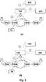
- Fig. 3it is illustrated an embodiment of the present invention.
- an end user 10wants to perform a given service such as (s)he wants to retrieve some information from the Internet, e.g. a web page or media content, that is typically done by accessing such information by means of an URL
- Such packetis intercepted and identified as a DNS request by the controller manager 101 of the augmented SDN controller 100.
- the packet interception by the controller manager 101could be possible for several reasons.
- the augmented SDN controller 100can incorporate DNS proxy functionalities.
- the DNS requestreaches the augmented SDN controller 100 as a first packet of a flow without not configured flow handling entry in the flow table, or that there is a specific pre-configured flow entry in the flow table redirecting all the DNS requests to the augmented SDN controller 100.
- the deciding module 102forwards (2) the end user request to the DNS server 150 for name resolution which determines the domain behind the URL and forwards the determined information to the deciding module 102.
- the determined name by the DNS server 150may be forwarded to the end user 10, either directly by the DNS server 150, or by the augmented SDN controller 100 if it is acting as DNS proxy.
- the name resolution provided to the end user 10is a conventional DNS resolution.
- the deciding module 102after receiving the information from the DNS sever 150, (3) queries the database 300 for retrieving the supplementary or fine-grained information for the DNS request (complemented with new fields) in order to prepare the communication network for the incoming flow. Finally, after the controller manager 101 processing, by executing an algorithm, the determined information provided by the DNS server 150 and the fine-grained information retrieved from the database 300, the controller manager 101 sets up (4) the required forwarding entries in the flow tables of the computer networking device 120a, in this particular embodiment a switch, in its domain or sub-network A, if necessary.
- the augmented SDN controller 100may also transfer (5) the relevant information about the incoming flow to other augmented SDN controllers 100a (to other deciding modules) in the end-to-end path where other end user(s) 20 may be connected. This can be done for instance based on a northbound interface with an orchestrator to assists them for preparing the corresponding network segments for the incoming traffic. Therefore, others augmented SDN controllers 100a in other network domains B of the communication network can preconfigure (6) the involved switches 120b, 120c in the end-to-end path, if needed, according to the information received by the augmented SDN controller 100 of the network domain A of the end user 10.
- a security systemfor instance for a Malware protection system that could detect and treat malicious traffic.
- this security systemwill include in the database 300 the relevant information about security based in the DNS information. Different kind of information could it be added:
- Security data related with domainsis included (1) in the database 300, so whenever the augmented SDN Controller 100 receives a device or a user DNS traffic flow, it will request (2) to the database 300 the supplemented security information around the domain request.
- the augmented SDN controller 100can execute (3) different actions based on the supplementary information. Therefore, the augmented SDN controller 100 can redirect in advance (4) all the traffic from that source to a specific network zone to treat the traffic (sinkhole sensors, user remediation captive portal, etc.), cleaning the traffic in the network, and protecting the source.
- the database 300includes (1) a sensitive information like a list of sensitive domains or a list of source IP addresses that must be treat different from the point of view of security (Banks online service, business transactional services, companies VPN access, etc.). The service provider or even the users can define these domains and include it in the database 300.
- the augmented SDN controller 100based in the received supplementary (2) information from the database 300 will prepare (3) the network with different actions: redirect access traffic coming into network from user to secure entry points (SecGW for 3G or 4G mobiles access, or VPN terminator, etc.) if the physical access is not secure; and redirect (5) the traffic towards to destination to devices or networks domains that will that will in charge of inspect (DPI, IDS) and supervise the traffic from the security point of view. Therefore, present invention allows the combination of the SDN capabilities and DNS information to prepare and optimize the traffic redirection avoiding complex techniques (routing protocols, filter policies, etc.).
- SecGWis defined in 3GPP TS 33.210 [5] in a general model to connect two non-secure domains, but in 3GPP TS 33.401 Section 11, [6] is applied to LTE mobile in order to protect physical access between eNB , MME and S-GW.
- Fig. 5illustrates a second example for a virtual data center in a generic cloud computing infrastructure (public, private and/or hybrid).
- Cloud Computingallows the sharing of the physical infrastructure in a multi-tenant fashion, thanks to the virtualization capabilities of existing operative systems and IT technologies in general.
- the resources allocated to one usercan be assigned in different datacenters and even change in time, without impact for the end user.
- There are several commercial offers based on cloud infrastructureswhere users of these systems are allowed to deploy virtual machines VM A , VM B in separated datacenters DC a , DC b .
- These Virtual Machines VM A , VM Bare intended to provide services, either internal or external to the end-user network. Because of the flexibility provided by these systems, the virtual machines VM A , VM B can be migrated between datacenters DC a , DC b without further impact.
- the most common and easy access to a given service running on a virtual machine VM Awill be via a DNS query, in order to hide the specific IP of the virtual machine VM A .
- the virtual datacenter DC awill deploy a DNS service where the resolution among the virtual machine naming and the corresponding IP is given, both for internal and external communication purposes.
- these cloud environmentsstart to be integrated with SDN-based solutions for connectivity provision.
- the SDN capabilitiescan be extended further than the datacenter limits, including also the connections in a WAN, for a smooth end to end connectivity solution.
- the proposed inventionbecomes beneficial because of the combination of both SDN and DNS for setting up in advance the required transport links in the virtual datacenter DC a environment. Even more, this connectivity can be re-adapted according to the allocation of new resources in a different datacenter DC b as in the virtual machine mobility case. Whatever new communications to a virtual machine VM A that needs a DNS query in an SDN environment will allow identify in advance the flows that will cross both datacenter DC a and WAN network.
- VNFsvirtual network functions
Landscapes
- Engineering & Computer Science (AREA)
- Computer Networks & Wireless Communication (AREA)
- Signal Processing (AREA)
- Business, Economics & Management (AREA)
- General Business, Economics & Management (AREA)
- Computer Hardware Design (AREA)
- Computer Security & Cryptography (AREA)
- Computing Systems (AREA)
- General Engineering & Computer Science (AREA)
- Data Exchanges In Wide-Area Networks (AREA)
Description
- The present invention generally relates to data networks. In particular, the invention relates to a network controller and to a computer implemented method for automatically define forwarding rules to configure a computer networking device of a communication network. The proposed network controller, or improved Software-Defined Networking (SDN) controller, automatically and proactively configures on-demand the needed rules in the communication network for an effective communication and makes use of DNS capabilities to identify in advance the new flows that will pass through the communication network.
- The standard behavior of a SDN network controller implies the reactive configuration of forwarding rules for any new flow that does not match any existing entry in a flow table. The setup process for any new rule starts once a new packet arrives at a computer networking device such as a switch in case said switch does not contain any specific entry in the flow table. In that case, the switch sends a flow request to the SDN controller which analyses the packet for defining an applicable rule that is finally configured in the switch. The rules consist of an action (e.g. forward to a certain port, drop, send to the network controller, etc.) determined by a match or arbitrary bits in the packet header (e.g., MAC address, IP address, VLAN tag, TCP port, etc.).
- The performance of this process depends on the switch and the SDN controller resources (CPU, memory, etc.) and can lead to a serious scalability issue, since the potential number of request to the network controller for a new rule is directly proportional to the number of distinct active flows in the communication network.
- The SDN paradigm was originally conceived for efficient communication between virtual (or physical) machines residing in datacenter environments. In this environment the applications hosted in different devices communicates with each other to provide a certain service.
- Nowadays the SDN concept is progressively gaining momentum and its application to conventional communication networks is envisaged. It is then needed to solve the potential scalability issues that central elements in a communication network could suffer (in this case, a SDN controller) due to the massive usage of the communication network by the end users.
- Apart from that, Domain Name Service (DNS) is a standardized protocol and one of the basic services needed in today's Internet. Apart from name resolution service, DNS it has been extended several uses. One is the DNS-SD or DNS Service discovery [1] that was defined with the aim of simplified the network clients to discover and user offered service by the network like, browsing or printing. Another common use is a DNS-based request routing by Content Delivery Networks (CDNs) that resolve a different IP address of the CDN Server based in its own criteria. One typical scenario is using IP source geolocation to resolve different IP address of the content Server, trying to offer contents physically as closed as possible to the source resolving IP address.
- Security Services based in DNS is another common practice. Fighting against spam and malware through a DNS-based Blackhole List (DNSBL) is a common practice.
- As mentioned before, the reactive configuration of the switch by the network controller is the common behavior of an SDN network (as can be seen, for instance, in the OpenFlow specification [2]), which can lead to serious scalability issues. An example of a solution evolved from the OpenFlow specification is the OpenDayLight project [3]. It provides a REST API for its controller platform which may configure the DNS servers for a controller node. Another example of an evolved solution is the HP Sentinel [4] that only uses the SDN technology to receive DNS traffic and allow or not said DNS traffic by progressing the DNS request based on local rules. Therefore, said solution only allows progressing or not a user request after having compared it with a predefined list of rules.
- On another hand, proactive configurations are implemented by network administrators directly specifying in the network controller flow policies without an actual knowledge of which flows will be created by the end user, then being generic, and not based on the real traffic that will pass through the network.
- Apart from that, rules can change over time according to the network needs, and the memory in the switches is limited, so no fine-grain rules can be pre-configured for all the potential flows in the network.
Finally, in a telecommunication environment is more than probable that more than one network domain (sub-network) should be passed through the flow for setting and end-to-end communication. Then it is needed to establish a communication between SDN controllers across the entire network in order to preconfigure the flow rule in advance end-to-end.WO2014142278 provides a Twice NAT function that can be used even within a single network. A control device comprises: a mapping-information management unit for managing mapping information in which host location information, mapped IP addresses, actual IP addresses and host names have been associated; and an instruction generation unit for instructing a forwarding node on the forwarding path of a packet from the host to translate the mapped IP address and the actual address indicated in the transmission source IP address and the transmission destination IP address, respectively, to the corresponding actual address and mapped IP address on the basis of the mapping information.
Scientific document'Internet Research Task Force SDNi: A Message Exchange Protocol for Software Defined Networks (SDNS)', draft-yin-sdn-sdni-00.txt, by H. Yin et al., 27 June 2012, discloses a protocol SDNi for the interface between Software Defined Networking (SDN) domains to exchange information between the domain SDN Controllers. It defines the concept of a SDN domain; its need, what its components are and how SDNi helps in interdomain communication. Scientific report 'SDN architecture' by the Open Networking Foundation (ONF), ONF TR-502, 30 June 2014, specifies the architecture of SDN. Based on an ONF introduction to SDN, it expands the principles of SDN and applies them to architectural components and interfaces. - [1] RFC6763. DNS Service discovery.
- [2] OpenFlow Switch Specification Version 1.3.0 (Wire Protocol 0x04) June 25, 2012. https://www.opennetworking.org/images/stories/downloads/sdn-resources/onf-specifications/openflow/openflow-spec-v1.3.0.pdf
- [3] http://www.opendaylight.org/project/technical-overview.
- [4] http://h17007.www1.hp.com/docs/interopny/4AA4-3871ENW.pdf
- [5] 3GPP TS 33.210. Network Domain Security (NDS).
- [6] 3GPP TS 33.401. 3GPP System Architecture Evolution (SAE); Security architecture.
- [7] https://datatracker.ietf.org/wg/sfc/charter/
- Embodiments of the present invention address these and/or other needs by providing a network controller, such as a SDN controller, for automatically define forwarding rules to configure a computer networking device, for instance a switch. The network controller which is compliant with several Control to Data-Plane Interfaces (CDPI) specifications such as OpenFlow, among others, is connected to a sub-network of a communication network and comprises:
- a controller manager that receives a request for a given service, and defines, by executing an algorithm, forwarding rules related to said service, and installs the defined forwarding rules into a computer networking device of the sub-network of the communication network in order to configure the computer networking device for said given service;
- a deciding module configured to communicate with the controller manager and configured to interact with a DNS server to receive a determined resolution for a DNS request of said request for said given service, and with a database to retrieve information supplementary for the DNS request, in order to assist the controller manager in performing the defining of the forwarding rules; and
- a plurality of interfaces for respectively allowing the communication of the deciding module with the controller manager, the DNS server and the database.
- In an embodiment the controller manager is connected to at least another computer networking device (for instance another switch) of said sub-network of the communication network in order to install the defined forwarding rules in said another computer networking device.
- In another embodiment, the first network controller is connected to at least a second network controller of a different and adjacent sub-network of the communication network in order the deciding module of said first network controller sending, through a corresponding interface, the relevant information about the incoming request, or flow, in particular, the determined resolution received from the DNS server and the retrieved information from the database to at least another deciding module included in said second network controller.
- According to the invention, the database includes: a reporting module for allowing the retrieval of said information supplementary for the DNS request through said interface by the deciding module; a collector module for collecting said information supplementary for the DNS request from different sources of information through a corresponding interface; and a database manager module for storing the collected information supplementary for the DNS request, said database manager having two different interfaces, a first one for communicating with the reporting module and a second one for communicating with the collector module.
- The different sources of information comprise internal information to a service provider of the communication network and external information to said service provider. Preferably, the internal information come from Operations Support Systems (OSS)/ Business Support Systems (BSS) at least including network topologies databases, inventories tools, monitoring network and flows and service graph orchestration, whereas the external information at least include security information, user's preferences and/or roaming information.
- Embodiments of the present invention also provide a computed implemented method for automatically define forwarding rules to configure a computer networking device, for instance a switch, wherein a controller manager of a network controller, such as a SDN controller, connected to a sub-network of a communication network receives a request for a given service and defines, by executing an algorithm, forwarding rules related to said given service, and installs the defined forwarding rules into a computer networking device of the sub-network of the communication network in order to configure the computer networking device for the given service. Moreover, and characteristically of the present invention, a deciding module of the network controller which communicates with the controller manager, forwards a DNS request of said request for the given service to a DNS server in order the latter determining a resolution for the DNS request; and retrieves, after having received the determined resolution from the DNS server, information supplementary for the DNS request from a database. Consequently, the deciding module assists the controller manager in performing the definition of the forwarding rules.
- According to the invention, before said retrieving of the information supplementary for the DNS request being performed, a collector module of the database collects the supplementary information from different sources of information and further stores the collected supplementary information in a database manager module of the database for allowing the retrieval by the deciding module.
- In an embodiment, the request for the given service is performed by a user connected to the computer networking device by means of a computing device such as a Tablet, a PC, a notebook, a Smartphone, etc.
- In another embodiment, the request for the given service is performed by a datacenter connected to the computer networking device.
- Therefore, present invention automatically and proactively allows the configuration of forwarding rules on-demand in the provided SDN controller taking as input the DNS traffic as consequence of a request for a given service made by an end user, for instance, a request for a domain name resolution function, in order to identify in advance the flow that can be created by the end user before such flow enters the communication network.
- In a communication/telecommunication network the end users access applications by relaying on DNS services, in order to get an IP address routable in the network from an URL specified by the user(s) when accessing a service (e.g. a web page or content).
- Hence, with present invention it is possible to know in advance the flow that will pass through the communication network, and automatically prepare the communication network to handle it by configuring appropriate rules in the provided SDN controller.
- Since the provided SDN controller allows a richer handling of the flow, the information kept in a separate database (queried in base to the DNS resolution) makes possible a fine-grain handling of the incoming flow (by incorporating supplementary information such as VLAN tag, MAC address, TCP/UDP ports, etc. or combination of them, that could be of interest for the domain for handling the expected incoming flows).
- The previous and other advantages and features will be more fully understood from the following detailed description of embodiments, with reference to the attached drawings, which must be considered in an illustrative and non-limiting manner, in which:
Fig. 1 is an illustration showing the structure and interfaces of the proposed network controller or SDN controller for automatically define forwarding rules to configure a computer networking device.Fig. 2 is an illustration showing the database structure and interfaces.Fig. 3 illustrates the high level process performed by the present invention according to some embodiments.Figs. 4 and5 are two different examples where present invention is of particular relevance.Fig. 4 is a security application example andFig. 5 is a virtual datacenter example in a cloud computing infrastructure.Fig. 1 illustrates the proposednetwork controller 100, or augmented SDN controller as will be call from now on. Theaugmented SDN controller 100 includes a conventional SDN controller module, in this description termed ascontroller manager 101, and is augmented by further including a decidingmodule 102 that interacts with aDNS server 150 and with adatabase 300.- The deciding
module 300 is in charge of: forwarding a DNS request to theDNS server 150; receiving the answer from theDNS server 150; querying thedatabase 300 for obtaining supplementary or fine-grain information for the DNS request; informing thecontroller manager 101 of a new flow entering the communication network; and forwarding to other deciding modules in the communication path that information for preparing their corresponding network segments. The information retrieved from theDNS server 150 could originate new forwarding rules or not, depending on the decision of the controller manager 101 (i.e. an entering flow could match an existing rule, then not producing any new flow rule). - The main interfaces of the
augmented SDN controller 100 are: - a interface SA used for the communication between the
controller manager 101 and the decidingmodule 102. From thecontroller manager 101 this interface is used for forwarding the DNS requests from theend user 10 to the decidingmodule 102, in order to reach theDNS server 150. From the decidingmodule 102, this interface transports the information retrieved from theDNS server 150 in order to inform thecontroller manager 101 about the characteristics of an incoming flow to the communication network, in order to configure in advance the affected computer networking devices (for instance the switches) in its network domain (or sub-network); - a interface SB used for the communication between the deciding
module 102 and theDNS server 150. From the decidingmodule 102 this interface is used to forward the end user DNS request to theDNS server 150 and for requesting the details for the new flow entering the network. From the DNS sever 150 this interface is used to provide the domain name resolution; - a interface SC used for the communication between the deciding
module 102 in the augmented SDN controller of the end user's network domain and one or more deciding module(s) pertaining to other augmented SDN controller(s) 100 in other network domains in the end-to-end path for distributing the flow details used for setting up flow rules along the path. From the decidingmodule 102 in the end user's domain, this interface transports the flow details. From the deciding module(s) in other network domains in the path, this interface is used to acknowledge the information received; and - a interface SD is used to query the
database 300 which contains the fine-grain details for the flow that can be used to configure new rules on the network elements along the end-to-end path. From theaugmented SDN Controller 100 this interface is used to obtain additional flow details useful in an SDN environment. From thedatabase 300, this interface is used to deliver such information. Fig. 2 illustrates the proposed database structure and interfaces. Thedatabase 300 is the specific module in charge of collect and store relevant information of the service provider (or network owner) of the communication network to improve the information offered by theDNS server 150. Several sources of information can feed thedatabase 300, like external Domains reputation lists, or Provider domains of interest to optimize the traffic, like own domains or client's domains. This information is retrieved by acollector module 303 and processed (including any analysis algorithms and relevant data extraction) and finally stored in adatabase manager module 302. The indexation of the database information is organized to combine DNS records data with topology and contextual information of the service provider, in this manner, reporting data to theaugmented SDN controller 100 will optimize the process time and reduce the delay. This latter task is done by areporting module 301 that will be able to deliver fine-grain flows information to construct rules and policies in theaugmented SDN controller 100.- The interfaces of the
database 300 are: - a interface SE used for the communication with the different sources of information. This interface transports two different types of data: one internal to the service provider and one external. Preferably internal sources of data will come from OSS/BSS, including Network topologies database, Inventories Tools, Monitoring Network, Flows and service graph orchestration. External sources of data will preferably include security information, client's preferences or roaming information. All this data feed the
collector module 303 with relevant information to adapt dynamically the communication network. This is the main source of information used by thecollector module 303 to realize the analysis and subsequence storage; - a interface SG that uses a normalized format to have a persistent storage of the information collected by the
collector module 303 in thedatabase manager module 302; - a interface SF that allows the communication between the reporting
module 301 and thedatabase manager module 302. This interface interchanges information of queries and response to thedatabase manager module 302. Moreover, in distributed models could also allow scalability and load balancing against several databases; and - the previously describe interface SD.
- With reference now to
Fig. 3 it is illustrated an embodiment of the present invention. In this case, (1) when anend user 10 wants to perform a given service such as (s)he wants to retrieve some information from the Internet, e.g. a web page or media content, that is typically done by accessing such information by means of an URL, (s)he performs a request for said service that generates a packet for DNS resolution. Such packet is intercepted and identified as a DNS request by thecontroller manager 101 of theaugmented SDN controller 100. The packet interception by thecontroller manager 101 could be possible for several reasons. For instance, theaugmented SDN controller 100 can incorporate DNS proxy functionalities. Other possibility is that the DNS request reaches theaugmented SDN controller 100 as a first packet of a flow without not configured flow handling entry in the flow table, or that there is a specific pre-configured flow entry in the flow table redirecting all the DNS requests to theaugmented SDN controller 100. - Then, the deciding
module 102 forwards (2) the end user request to theDNS server 150 for name resolution which determines the domain behind the URL and forwards the determined information to the decidingmodule 102. The determined name by theDNS server 150 may be forwarded to theend user 10, either directly by theDNS server 150, or by theaugmented SDN controller 100 if it is acting as DNS proxy. In any case, the name resolution provided to theend user 10 is a conventional DNS resolution. - The deciding
module 102, after receiving the information from the DNS sever 150, (3) queries thedatabase 300 for retrieving the supplementary or fine-grained information for the DNS request (complemented with new fields) in order to prepare the communication network for the incoming flow. Finally, after thecontroller manager 101 processing, by executing an algorithm, the determined information provided by theDNS server 150 and the fine-grained information retrieved from thedatabase 300, thecontroller manager 101 sets up (4) the required forwarding entries in the flow tables of thecomputer networking device 120a, in this particular embodiment a switch, in its domain or sub-network A, if necessary. - The augmented SDN controller 100 (in particular the deciding
module 102 of the augmented SDN controller 100) may also transfer (5) the relevant information about the incoming flow to otheraugmented SDN controllers 100a (to other deciding modules) in the end-to-end path where other end user(s) 20 may be connected. This can be done for instance based on a northbound interface with an orchestrator to assists them for preparing the corresponding network segments for the incoming traffic. Therefore, others augmentedSDN controllers 100a in other network domains B of the communication network can preconfigure (6) the involvedswitches augmented SDN controller 100 of the network domain A of theend user 10. - Finally the end user flow (7) towards the desired destination passes through the communication network without triggering any reactive flow rule configuration.
- Next are detailed two different examples in which present invention is of particular relevance. It has to be noted that each of following examples has entity as a whole by themselves because are specific applications of the invention, but also can be understood as a mechanism to define the path and the order between communication network nodes that offer service functions in what is known as Service Function Chaining (SFC), i.e. the abstracted view of the required service functions and the order in which they are to be applied (Detail description is available in IETF WG SFC [7]).
- With reference to
Fig. 4 it is illustrated a first example for a security system, for instance for a Malware protection system that could detect and treat malicious traffic. In particular, this security system will include in thedatabase 300 the relevant information about security based in the DNS information. Different kind of information could it be added: - I. Blacklist domains, including known malicious content domains for spam, phishing, malware download, Botnets controllers command & control;
- II. Abnormal DNS traffic behavioral, some examples are excessive and DNS queries rate per origin (MAC address it will the best unique origin identification, but not the only one) that identify a bot based in Domain generation algorithm (DGA) or a massive MX type queries that indicate SPAM traffic generation;
- III. Rare domains names, that include unintelligible or with no sense words, automatic generated and used for malware hosting.
- Security data related with domains is included (1) in the
database 300, so whenever theaugmented SDN Controller 100 receives a device or a user DNS traffic flow, it will request (2) to thedatabase 300 the supplemented security information around the domain request. When the information retrieved from thedatabase 300 confirms a security risk (malware related presence in the Domain), theaugmented SDN controller 100 can execute (3) different actions based on the supplementary information. Therefore, theaugmented SDN controller 100 can redirect in advance (4) all the traffic from that source to a specific network zone to treat the traffic (sinkhole sensors, user remediation captive portal, etc.), cleaning the traffic in the network, and protecting the source. - Another additional flavor of application case for this security embodiment is a security traffic steering based in pre-programmed information. In this case the
database 300 includes (1) a sensitive information like a list of sensitive domains or a list of source IP addresses that must be treat different from the point of view of security (Banks online service, business transactional services, companies VPN access, etc.). The service provider or even the users can define these domains and include it in thedatabase 300. Theaugmented SDN controller 100, based in the received supplementary (2) information from thedatabase 300 will prepare (3) the network with different actions: redirect access traffic coming into network from user to secure entry points (SecGW for 3G or 4G mobiles access, or VPN terminator, etc.) if the physical access is not secure; and redirect (5) the traffic towards to destination to devices or networks domains that will that will in charge of inspect (DPI, IDS) and supervise the traffic from the security point of view. Therefore, present invention allows the combination of the SDN capabilities and DNS information to prepare and optimize the traffic redirection avoiding complex techniques (routing protocols, filter policies, etc.). - It has to be noted that SecGW is defined in 3GPP TS 33.210 [5] in a general model to connect two non-secure domains, but in 3GPP TS 33.401 Section 11, [6] is applied to LTE mobile in order to protect physical access between eNB , MME and S-GW.
Fig. 5 illustrates a second example for a virtual data center in a generic cloud computing infrastructure (public, private and/or hybrid). Cloud Computing allows the sharing of the physical infrastructure in a multi-tenant fashion, thanks to the virtualization capabilities of existing operative systems and IT technologies in general. The resources allocated to one user can be assigned in different datacenters and even change in time, without impact for the end user. There are several commercial offers based on cloud infrastructures where users of these systems are allowed to deploy virtual machines VMA, VMB in separated datacenters DCa, DCb. These Virtual Machines VMA, VMB are intended to provide services, either internal or external to the end-user network. Because of the flexibility provided by these systems, the virtual machines VMA, VMB can be migrated between datacenters DCa, DCb without further impact.- The most common and easy access to a given service running on a virtual machine VMA will be via a DNS query, in order to hide the specific IP of the virtual machine VMA. Then, as a common way of procedure, the virtual datacenter DCa will deploy a DNS service where the resolution among the virtual machine naming and the corresponding IP is given, both for internal and external communication purposes. Furthermore these cloud environments start to be integrated with SDN-based solutions for connectivity provision. The SDN capabilities can be extended further than the datacenter limits, including also the connections in a WAN, for a smooth end to end connectivity solution.
- In this situation, the proposed invention becomes beneficial because of the combination of both SDN and DNS for setting up in advance the required transport links in the virtual datacenter DCa environment. Even more, this connectivity can be re-adapted according to the allocation of new resources in a different datacenter DCb as in the virtual machine mobility case. Whatever new communications to a virtual machine VMA that needs a DNS query in an SDN environment will allow identify in advance the flows that will cross both datacenter DCa and WAN network.
- Thanks to Network Functions Virtualization (NFV) technologies, it becomes possible to instantiate virtual network functions (VNFs) in datacenter computing resources. In consequence the embodiment presented here can be used as a mechanism to define service function chaining between such VNFs.
- The scope of the present invention is determined by the claims that follow.
Claims (11)
- A system for automatically defining forwarding rules to configure a computer networking device (120a), comprising a network controller (100) and a database (300), whereby said network controller (100) is connected to a sub-network (A) of a communication network and comprises:- a controller manager (101) configured to receive a request for a given service and to define, by executing an algorithm, forwarding rules related to said service and to install the defined forwarding rules into a computer networking device (120a) of the sub-network (A) of the communication network in order to configure the computer networking device (120a) for said given service,characterized in that the network controller (100) further comprises:- a deciding module (102) configured to communicate with the controller manager (101) and configured to interact with a Domain Name System, DNS, server (150) to receive a determined resolution for a DNS request of said request for said given service, and with a database (300) configured to retrieve supplementary information for the DNS request, in order to assist the controller manager (101) in performing the definition of the forwarding rules, said database (300) configured to be fed by different sources of information; and- a plurality of interfaces (SA, SB, SD) for allowing the communication of the deciding module (102) with the controller manager (101), the DNS server (150) and the database (300),wherein the database (300) is configured to organize indexation of the database information to combine DNS records data with topology and contextual information of a service provider of the communication network, and
wherein the different sources of information comprise information internal to said service provider of the communication network and information external to said service provider, wherein the internal information comes from Operations Support Systems, OSS, or Business Support Systems, BSS, at least including network topologies databases, inventories tools, monitoring network and flows and service graph orchestration; and the external information at least includes security information, user's preferences and/or roaming information. - The system of claim 1, wherein the controller manager (101) is connected to at least another computer networking device (120) of said sub-network (A) of the communication network in order to install the defined forwarding rules in said another computer networking device (120).
- The system of any of the previous claims, wherein the first network controller (100) is connected to at least a second network controller (100a) of a sub-network (B) of the communication network adjacent to the sub-network (A) wherein the deciding module (102) of the first network controller (100) is configured to send, through a corresponding interface (Sc), the determined resolution received from the DNS server (150) and the retrieved supplementary information from the database (300) to at least another deciding module (102a) included in said second network controller (100a).
- The system of claim 1, wherein said database (300) comprises:- a reporting module (301) configured to allow the retrieval of said supplementary information for the DNS request through said interface (SD) by the deciding module (102);- a collector module (303) configured to collect said supplementary information for the DNS request from said different sources of information through a corresponding interface (SE); and- a database manager module (302) configured to store the collected supplementary information for the DNS request, said database manager (302) having two different interfaces, a first one (SF) for communicating with the reporting module (301) and a second one (SG) for communicating with the collector module (303).
- The system of any of the previous claims, wherein the computer networking device (120a, 120b) comprises a switch.
- The network controller of previous claims, wherein the controller manager (101) complies with Control to Data-Plane Interface, CDPI, specifications.
- A method for automatically defining forwarding rules to configure a computer networking device (120a), the method comprising:- receiving, by a controller manager (101) of a network controller (100) connected to a sub-network (A) of a communication network, a request for a given service; and- defining, by said controller manager (101), by executing an algorithm, forwarding rules related to said given service, and installing the defined forwarding rules into a computer networking device (120a) of the sub-network (A) of the communication network in order to configure the computer networking device (120a) for the given service,characterized in that the method comprises:- forwarding, by a deciding module (102) of the network controller (100) in communication with the controller manager (101), a Domain Name System, DNS, request of said request for the given service to a DNS server (150), the latter determining a resolution for the DNS request and further forwarding the determined resolution to the deciding module (102); and- retrieving, by the deciding module (102), after receiving the determined resolution from the DNS server (150), supplementary information for the DNS request from a database (300), the database (300) being fed by different sources of information, so that the deciding module (102) assists the controller manager (101) in performing the definition of the forwarding rules,wherein indexation of the database information inside the database (300) is organized to combine DNS records data with topology and contextual information of a service provider of the communication network, and
wherein the different sources of information comprise information internal to said service provider of the communication network and information external to said service provider, wherein the internal information comes from Operations Support Systems, OSS, or Business Support Systems, BSS, at least including network topologies databases, inventories tools, monitoring network and flows and service graph orchestration; and the external information at least includes security information, user's preferences and/or roaming information. - The method of claim 7, further comprising installing, by the controller manager (101), the defined forwarding rules into at least another computer networking device (120) of said sub-network (A) of the communication network.
- The method of previous claim 7 or 8, further comprising sending, by the deciding module (102), the determined resolution received from the DNS server (150) and the retrieved supplementary information from the database (300) to at least another deciding module (102a) included in another network controller (100a) of a sub-network (B) of the communication network adjacent to the sub-network (A).
- The method of any of previous claims 7 to 9, wherein the request for the given service is performed by a user (10) connected to the computer networking device (120a) by means of a computing device.
- The method of any of previous claims 7 to 9, wherein the request for the given service is performed by at least one datacenter connected to the computer networking device (120a).
Priority Applications (3)
| Application Number | Priority Date | Filing Date | Title |
|---|---|---|---|
| ES14382453.0TES2663410T3 (en) | 2014-11-14 | 2014-11-14 | A network controller and a computerized method implemented to automatically define forwarding rules to configure a computer network interconnect device |
| EP14382453.0AEP3021534B1 (en) | 2014-11-14 | 2014-11-14 | A network controller and a computer implemented method for automatically define forwarding rules to configure a computer networking device |
| US14/940,429US9806944B2 (en) | 2014-11-14 | 2015-11-13 | Network controller and a computer implemented method for automatically define forwarding rules to configure a computer networking device |
Applications Claiming Priority (1)
| Application Number | Priority Date | Filing Date | Title |
|---|---|---|---|
| EP14382453.0AEP3021534B1 (en) | 2014-11-14 | 2014-11-14 | A network controller and a computer implemented method for automatically define forwarding rules to configure a computer networking device |
Publications (2)
| Publication Number | Publication Date |
|---|---|
| EP3021534A1 EP3021534A1 (en) | 2016-05-18 |
| EP3021534B1true EP3021534B1 (en) | 2018-01-10 |
Family
ID=51982507
Family Applications (1)
| Application Number | Title | Priority Date | Filing Date |
|---|---|---|---|
| EP14382453.0AActiveEP3021534B1 (en) | 2014-11-14 | 2014-11-14 | A network controller and a computer implemented method for automatically define forwarding rules to configure a computer networking device |
Country Status (3)
| Country | Link |
|---|---|
| US (1) | US9806944B2 (en) |
| EP (1) | EP3021534B1 (en) |
| ES (1) | ES2663410T3 (en) |
Cited By (1)
| Publication number | Priority date | Publication date | Assignee | Title |
|---|---|---|---|---|
| US11811730B1 (en) | 2022-10-11 | 2023-11-07 | International Business Machines Corporation | Determining domain name system forwarding rules in a multi-cloud environment |
Families Citing this family (65)
| Publication number | Priority date | Publication date | Assignee | Title |
|---|---|---|---|---|
| US8028090B2 (en) | 2008-11-17 | 2011-09-27 | Amazon Technologies, Inc. | Request routing utilizing client location information |
| US7991910B2 (en) | 2008-11-17 | 2011-08-02 | Amazon Technologies, Inc. | Updating routing information based on client location |
| US8601090B1 (en) | 2008-03-31 | 2013-12-03 | Amazon Technologies, Inc. | Network resource identification |
| US8447831B1 (en) | 2008-03-31 | 2013-05-21 | Amazon Technologies, Inc. | Incentive driven content delivery |
| US7970820B1 (en) | 2008-03-31 | 2011-06-28 | Amazon Technologies, Inc. | Locality based content distribution |
| US8321568B2 (en) | 2008-03-31 | 2012-11-27 | Amazon Technologies, Inc. | Content management |
| US8606996B2 (en) | 2008-03-31 | 2013-12-10 | Amazon Technologies, Inc. | Cache optimization |
| US7962597B2 (en) | 2008-03-31 | 2011-06-14 | Amazon Technologies, Inc. | Request routing based on class |
| US9407681B1 (en) | 2010-09-28 | 2016-08-02 | Amazon Technologies, Inc. | Latency measurement in resource requests |
| US8073940B1 (en) | 2008-11-17 | 2011-12-06 | Amazon Technologies, Inc. | Managing content delivery network service providers |
| US8688837B1 (en) | 2009-03-27 | 2014-04-01 | Amazon Technologies, Inc. | Dynamically translating resource identifiers for request routing using popularity information |
| US8756341B1 (en) | 2009-03-27 | 2014-06-17 | Amazon Technologies, Inc. | Request routing utilizing popularity information |
| US8412823B1 (en) | 2009-03-27 | 2013-04-02 | Amazon Technologies, Inc. | Managing tracking information entries in resource cache components |
| US8782236B1 (en) | 2009-06-16 | 2014-07-15 | Amazon Technologies, Inc. | Managing resources using resource expiration data |
| US8397073B1 (en) | 2009-09-04 | 2013-03-12 | Amazon Technologies, Inc. | Managing secure content in a content delivery network |
| US8433771B1 (en) | 2009-10-02 | 2013-04-30 | Amazon Technologies, Inc. | Distribution network with forward resource propagation |
| US9495338B1 (en) | 2010-01-28 | 2016-11-15 | Amazon Technologies, Inc. | Content distribution network |
| US9003035B1 (en) | 2010-09-28 | 2015-04-07 | Amazon Technologies, Inc. | Point of presence management in request routing |
| US9712484B1 (en) | 2010-09-28 | 2017-07-18 | Amazon Technologies, Inc. | Managing request routing information utilizing client identifiers |
| US8468247B1 (en) | 2010-09-28 | 2013-06-18 | Amazon Technologies, Inc. | Point of presence management in request routing |
| US10958501B1 (en) | 2010-09-28 | 2021-03-23 | Amazon Technologies, Inc. | Request routing information based on client IP groupings |
| US8452874B2 (en) | 2010-11-22 | 2013-05-28 | Amazon Technologies, Inc. | Request routing processing |
| US10467042B1 (en) | 2011-04-27 | 2019-11-05 | Amazon Technologies, Inc. | Optimized deployment based upon customer locality |
| US10623408B1 (en) | 2012-04-02 | 2020-04-14 | Amazon Technologies, Inc. | Context sensitive object management |
| US9154551B1 (en) | 2012-06-11 | 2015-10-06 | Amazon Technologies, Inc. | Processing DNS queries to identify pre-processing information |
| US9323577B2 (en) | 2012-09-20 | 2016-04-26 | Amazon Technologies, Inc. | Automated profiling of resource usage |
| US10205698B1 (en) | 2012-12-19 | 2019-02-12 | Amazon Technologies, Inc. | Source-dependent address resolution |
| US9294391B1 (en) | 2013-06-04 | 2016-03-22 | Amazon Technologies, Inc. | Managing network computing components utilizing request routing |
| US10097448B1 (en) | 2014-12-18 | 2018-10-09 | Amazon Technologies, Inc. | Routing mode and point-of-presence selection service |
| US10587698B2 (en)* | 2015-02-25 | 2020-03-10 | Futurewei Technologies, Inc. | Service function registration mechanism and capability indexing |
| US10225326B1 (en) | 2015-03-23 | 2019-03-05 | Amazon Technologies, Inc. | Point of presence based data uploading |
| US9819567B1 (en) | 2015-03-30 | 2017-11-14 | Amazon Technologies, Inc. | Traffic surge management for points of presence |
| US9736185B1 (en)* | 2015-04-21 | 2017-08-15 | Infoblox Inc. | DNS or network metadata policy for network control |
| US9832141B1 (en) | 2015-05-13 | 2017-11-28 | Amazon Technologies, Inc. | Routing based request correlation |
| US9774619B1 (en) | 2015-09-24 | 2017-09-26 | Amazon Technologies, Inc. | Mitigating network attacks |
| US10270878B1 (en) | 2015-11-10 | 2019-04-23 | Amazon Technologies, Inc. | Routing for origin-facing points of presence |
| US10257307B1 (en) | 2015-12-11 | 2019-04-09 | Amazon Technologies, Inc. | Reserved cache space in content delivery networks |
| US10348639B2 (en) | 2015-12-18 | 2019-07-09 | Amazon Technologies, Inc. | Use of virtual endpoints to improve data transmission rates |
| CN108141373B (en)* | 2016-04-20 | 2021-04-16 | 安华高科技股份有限公司 | Federated Communication Framework for Network Controllers |
| US10075551B1 (en) | 2016-06-06 | 2018-09-11 | Amazon Technologies, Inc. | Request management for hierarchical cache |
| US10110694B1 (en) | 2016-06-29 | 2018-10-23 | Amazon Technologies, Inc. | Adaptive transfer rate for retrieving content from a server |
| CN107733799B (en)* | 2016-08-11 | 2021-09-21 | 新华三技术有限公司 | Message transmission method and device |
| US10992536B2 (en) | 2016-08-15 | 2021-04-27 | At&T Intellectual Property I, L.P. | Method and apparatus to control anycast traffic using a software defined network controller |
| US9992086B1 (en) | 2016-08-23 | 2018-06-05 | Amazon Technologies, Inc. | External health checking of virtual private cloud network environments |
| US10033691B1 (en)* | 2016-08-24 | 2018-07-24 | Amazon Technologies, Inc. | Adaptive resolution of domain name requests in virtual private cloud network environments |
| US10616250B2 (en) | 2016-10-05 | 2020-04-07 | Amazon Technologies, Inc. | Network addresses with encoded DNS-level information |
| US10476942B2 (en)* | 2016-12-21 | 2019-11-12 | International Business Machines Corporation | DNS resolution of overlapping domains in a multi-tenant computing environment |
| US10372499B1 (en) | 2016-12-27 | 2019-08-06 | Amazon Technologies, Inc. | Efficient region selection system for executing request-driven code |
| US10831549B1 (en) | 2016-12-27 | 2020-11-10 | Amazon Technologies, Inc. | Multi-region request-driven code execution system |
| US10938884B1 (en) | 2017-01-30 | 2021-03-02 | Amazon Technologies, Inc. | Origin server cloaking using virtual private cloud network environments |
| US10503613B1 (en) | 2017-04-21 | 2019-12-10 | Amazon Technologies, Inc. | Efficient serving of resources during server unavailability |
| US11075987B1 (en) | 2017-06-12 | 2021-07-27 | Amazon Technologies, Inc. | Load estimating content delivery network |
| US10447648B2 (en) | 2017-06-19 | 2019-10-15 | Amazon Technologies, Inc. | Assignment of a POP to a DNS resolver based on volume of communications over a link between client devices and the POP |
| US10742593B1 (en) | 2017-09-25 | 2020-08-11 | Amazon Technologies, Inc. | Hybrid content request routing system |
| US10592578B1 (en) | 2018-03-07 | 2020-03-17 | Amazon Technologies, Inc. | Predictive content push-enabled content delivery network |
| US10798005B2 (en)* | 2018-09-13 | 2020-10-06 | International Business Machines Corporation | Optimizing application throughput |
| US10862852B1 (en)* | 2018-11-16 | 2020-12-08 | Amazon Technologies, Inc. | Resolution of domain name requests in heterogeneous network environments |
| US11025747B1 (en) | 2018-12-12 | 2021-06-01 | Amazon Technologies, Inc. | Content request pattern-based routing system |
| US11218381B2 (en) | 2019-10-04 | 2022-01-04 | Cisco Technology, Inc. | Service tagging optimization for intent-based networking |
| US11201799B2 (en)* | 2019-10-15 | 2021-12-14 | Cisco Technology, Inc. | Intelligent selection of vantage points for monitoring subservices based on potential impact to services |
| US11088928B2 (en) | 2019-10-15 | 2021-08-10 | Cisco Technology, Inc. | Service aware conditional path monitoring |
| US11228507B2 (en) | 2019-12-05 | 2022-01-18 | Cisco Technology, Inc. | Baselining service-tagged data from subservices of a service for service assurance |
| US20210176125A1 (en)* | 2019-12-10 | 2021-06-10 | James Kyriannis | Programmable switching device for network infrastructures |
| CN113383531B (en)* | 2019-12-25 | 2022-10-11 | 华为技术有限公司 | Forwarding equipment, network card and message forwarding method |
| CN114866496B (en)* | 2022-03-30 | 2023-06-20 | 清华大学 | Intelligent network cooperation device and method |
Family Cites Families (13)
| Publication number | Priority date | Publication date | Assignee | Title |
|---|---|---|---|---|
| US20140269724A1 (en)* | 2013-03-04 | 2014-09-18 | Telefonaktiebolaget L M Ericsson (Publ) | Method and devices for forwarding ip data packets in an access network |
| JPWO2014142278A1 (en)* | 2013-03-14 | 2017-02-16 | 日本電気株式会社 | Control device, communication system, communication method, and program |
| US10263848B2 (en)* | 2013-03-20 | 2019-04-16 | Wolting Holding B.V. | Compiler for and method for software defined networks |
| WO2014166551A1 (en)* | 2013-04-12 | 2014-10-16 | Nec Europe Ltd. | Method and system for providing an information centric network |
| WO2015023537A2 (en)* | 2013-08-16 | 2015-02-19 | Interdigital Patent Holdings, Inc. | Methods and apparatus for hash routing in software defined networking |
| US9203711B2 (en)* | 2013-09-24 | 2015-12-01 | International Business Machines Corporation | Port mirroring for sampling measurement of network flows |
| EP3063923B1 (en)* | 2013-10-29 | 2019-10-16 | Telefonaktiebolaget LM Ericsson (publ) | Control of a chain of services |
| US20150124622A1 (en)* | 2013-11-01 | 2015-05-07 | Movik Networks, Inc. | Multi-Interface, Multi-Layer State-full Load Balancer For RAN-Analytics Deployments In Multi-Chassis, Cloud And Virtual Server Environments |
| US9379931B2 (en)* | 2014-05-16 | 2016-06-28 | Cisco Technology, Inc. | System and method for transporting information to services in a network environment |
| US9641429B2 (en)* | 2014-06-18 | 2017-05-02 | Radware, Ltd. | Predictive traffic steering over software defined networks |
| KR101945886B1 (en)* | 2014-06-27 | 2019-02-11 | 노키아 솔루션스 앤드 네트웍스 오와이 | Ultra high-speed mobile network based on layer-2 switching |
| US9781004B2 (en)* | 2014-10-16 | 2017-10-03 | Cisco Technology, Inc. | Discovering and grouping application endpoints in a network environment |
| US10285110B2 (en)* | 2014-11-04 | 2019-05-07 | At&T Intellectual Property I, L.P. | Intelligent traffic routing |
- 2014
- 2014-11-14EPEP14382453.0Apatent/EP3021534B1/enactiveActive
- 2014-11-14ESES14382453.0Tpatent/ES2663410T3/enactiveActive
- 2015
- 2015-11-13USUS14/940,429patent/US9806944B2/enactiveActive
Non-Patent Citations (1)
| Title |
|---|
| None* |
Cited By (1)
| Publication number | Priority date | Publication date | Assignee | Title |
|---|---|---|---|---|
| US11811730B1 (en) | 2022-10-11 | 2023-11-07 | International Business Machines Corporation | Determining domain name system forwarding rules in a multi-cloud environment |
Also Published As
| Publication number | Publication date |
|---|---|
| ES2663410T3 (en) | 2018-04-12 |
| US9806944B2 (en) | 2017-10-31 |
| US20160142251A1 (en) | 2016-05-19 |
| EP3021534A1 (en) | 2016-05-18 |
Similar Documents
| Publication | Publication Date | Title |
|---|---|---|
| EP3021534B1 (en) | A network controller and a computer implemented method for automatically define forwarding rules to configure a computer networking device | |
| US12184451B2 (en) | Systems and methods for providing a global virtual network (GVN) | |
| US9967346B2 (en) | Passing data over virtual links | |
| EP3189690B1 (en) | Method and apparatuses for enabling routing of data packets between a wireless device and a service provider based in the local service cloud | |
| US11824897B2 (en) | Dynamic security scaling | |
| US20160080263A1 (en) | Sdn-based service chaining system | |
| KR20220028102A (en) | Methods and systems for effective cyber protection of mobile devices | |
| CN112291294A (en) | Inline service switch | |
| JP2011160041A (en) | Front end system and front end processing method | |
| US9967140B2 (en) | Virtual links for network appliances | |
| KR101527377B1 (en) | Service chaining system based on software defined networks | |
| KR101746105B1 (en) | Openflow switch capable of service chaining | |
| Adeniji et al. | A model for network virtualization with openflow protocol in software-defined network | |
| CN113824808B (en) | Method and system for network address translation penetration using an intermediate meeting proxy | |
| Jeong et al. | Lisp controller: a centralized lisp management system for isp networks | |
| US20250039151A1 (en) | Load balancing secure network traffic | |
| US20250039150A1 (en) | Load balancing secure network traffic | |
| KR101739100B1 (en) | Method of controlling openflow switch capable of service chaining and controller thereof | |
| KR101739097B1 (en) | Service chaining method in openflow switch | |
| US11258720B2 (en) | Flow-based isolation in a service network implemented over a software-defined network | |
| Lakshmanan | Enhanced Software Defined Networking (SDN) with security & performance in cloud computing | |
| WO2025024378A1 (en) | Load balancing secure network traffic | |
| KR20180085592A (en) | Virtual router system and method to integrate with openstack based orchestration | |
| KR20180085475A (en) | Virtual router api interface to integrate with openstack based orchestration |
Legal Events
| Date | Code | Title | Description |
|---|---|---|---|
| PUAI | Public reference made under article 153(3) epc to a published international application that has entered the european phase | Free format text:ORIGINAL CODE: 0009012 | |
| AK | Designated contracting states | Kind code of ref document:A1 Designated state(s):AL AT BE BG CH CY CZ DE DK EE ES FI FR GB GR HR HU IE IS IT LI LT LU LV MC MK MT NL NO PL PT RO RS SE SI SK SM TR | |
| AX | Request for extension of the european patent | Extension state:BA ME | |
| STAA | Information on the status of an ep patent application or granted ep patent | Free format text:STATUS: REQUEST FOR EXAMINATION WAS MADE | |
| 17P | Request for examination filed | Effective date:20161115 | |
| RBV | Designated contracting states (corrected) | Designated state(s):AL AT BE BG CH CY CZ DE DK EE ES FI FR GB GR HR HU IE IS IT LI LT LU LV MC MK MT NL NO PL PT RO RS SE SI SK SM TR | |
| REG | Reference to a national code | Ref country code:DE Ref legal event code:R079 Ref document number:602014019810 Country of ref document:DE Free format text:PREVIOUS MAIN CLASS: H04L0012701000 Ipc:H04L0012715000 | |
| RIC1 | Information provided on ipc code assigned before grant | Ipc:H04L 12/715 20130101AFI20170515BHEP Ipc:H04L 29/06 20060101ALI20170515BHEP Ipc:H04L 29/12 20060101ALI20170515BHEP Ipc:H04L 12/717 20130101ALN20170515BHEP | |
| GRAP | Despatch of communication of intention to grant a patent | Free format text:ORIGINAL CODE: EPIDOSNIGR1 | |
| STAA | Information on the status of an ep patent application or granted ep patent | Free format text:STATUS: GRANT OF PATENT IS INTENDED | |
| RIC1 | Information provided on ipc code assigned before grant | Ipc:H04L 29/12 20060101ALI20170530BHEP Ipc:H04L 12/715 20130101AFI20170530BHEP Ipc:H04L 29/06 20060101ALI20170530BHEP Ipc:H04L 12/717 20130101ALN20170530BHEP | |
| INTG | Intention to grant announced | Effective date:20170626 | |
| GRAS | Grant fee paid | Free format text:ORIGINAL CODE: EPIDOSNIGR3 | |
| GRAA | (expected) grant | Free format text:ORIGINAL CODE: 0009210 | |
| STAA | Information on the status of an ep patent application or granted ep patent | Free format text:STATUS: THE PATENT HAS BEEN GRANTED | |
| AK | Designated contracting states | Kind code of ref document:B1 Designated state(s):AL AT BE BG CH CY CZ DE DK EE ES FI FR GB GR HR HU IE IS IT LI LT LU LV MC MK MT NL NO PL PT RO RS SE SI SK SM TR | |
| REG | Reference to a national code | Ref country code:CH Ref legal event code:EP Ref country code:AT Ref legal event code:REF Ref document number:963573 Country of ref document:AT Kind code of ref document:T Effective date:20180115 | |
| REG | Reference to a national code | Ref country code:IE Ref legal event code:FG4D | |
| REG | Reference to a national code | Ref country code:DE Ref legal event code:R096 Ref document number:602014019810 Country of ref document:DE | |
| REG | Reference to a national code | Ref country code:ES Ref legal event code:FG2A Ref document number:2663410 Country of ref document:ES Kind code of ref document:T3 Effective date:20180412 | |
| REG | Reference to a national code | Ref country code:NL Ref legal event code:MP Effective date:20180110 | |
| REG | Reference to a national code | Ref country code:AT Ref legal event code:MK05 Ref document number:963573 Country of ref document:AT Kind code of ref document:T Effective date:20180110 | |
| PG25 | Lapsed in a contracting state [announced via postgrant information from national office to epo] | Ref country code:NL Free format text:LAPSE BECAUSE OF FAILURE TO SUBMIT A TRANSLATION OF THE DESCRIPTION OR TO PAY THE FEE WITHIN THE PRESCRIBED TIME-LIMIT Effective date:20180110 | |
| PG25 | Lapsed in a contracting state [announced via postgrant information from national office to epo] | Ref country code:LT Free format text:LAPSE BECAUSE OF FAILURE TO SUBMIT A TRANSLATION OF THE DESCRIPTION OR TO PAY THE FEE WITHIN THE PRESCRIBED TIME-LIMIT Effective date:20180110 Ref country code:CY Free format text:LAPSE BECAUSE OF FAILURE TO SUBMIT A TRANSLATION OF THE DESCRIPTION OR TO PAY THE FEE WITHIN THE PRESCRIBED TIME-LIMIT Effective date:20180110 Ref country code:FI Free format text:LAPSE BECAUSE OF FAILURE TO SUBMIT A TRANSLATION OF THE DESCRIPTION OR TO PAY THE FEE WITHIN THE PRESCRIBED TIME-LIMIT Effective date:20180110 Ref country code:NO Free format text:LAPSE BECAUSE OF FAILURE TO SUBMIT A TRANSLATION OF THE DESCRIPTION OR TO PAY THE FEE WITHIN THE PRESCRIBED TIME-LIMIT Effective date:20180410 Ref country code:HR Free format text:LAPSE BECAUSE OF FAILURE TO SUBMIT A TRANSLATION OF THE DESCRIPTION OR TO PAY THE FEE WITHIN THE PRESCRIBED TIME-LIMIT Effective date:20180110 | |
| PG25 | Lapsed in a contracting state [announced via postgrant information from national office to epo] | Ref country code:AT Free format text:LAPSE BECAUSE OF FAILURE TO SUBMIT A TRANSLATION OF THE DESCRIPTION OR TO PAY THE FEE WITHIN THE PRESCRIBED TIME-LIMIT Effective date:20180110 Ref country code:GR Free format text:LAPSE BECAUSE OF FAILURE TO SUBMIT A TRANSLATION OF THE DESCRIPTION OR TO PAY THE FEE WITHIN THE PRESCRIBED TIME-LIMIT Effective date:20180411 Ref country code:BG Free format text:LAPSE BECAUSE OF FAILURE TO SUBMIT A TRANSLATION OF THE DESCRIPTION OR TO PAY THE FEE WITHIN THE PRESCRIBED TIME-LIMIT Effective date:20180410 Ref country code:PL Free format text:LAPSE BECAUSE OF FAILURE TO SUBMIT A TRANSLATION OF THE DESCRIPTION OR TO PAY THE FEE WITHIN THE PRESCRIBED TIME-LIMIT Effective date:20180110 Ref country code:IS Free format text:LAPSE BECAUSE OF FAILURE TO SUBMIT A TRANSLATION OF THE DESCRIPTION OR TO PAY THE FEE WITHIN THE PRESCRIBED TIME-LIMIT Effective date:20180510 Ref country code:SE Free format text:LAPSE BECAUSE OF FAILURE TO SUBMIT A TRANSLATION OF THE DESCRIPTION OR TO PAY THE FEE WITHIN THE PRESCRIBED TIME-LIMIT Effective date:20180110 Ref country code:LV Free format text:LAPSE BECAUSE OF FAILURE TO SUBMIT A TRANSLATION OF THE DESCRIPTION OR TO PAY THE FEE WITHIN THE PRESCRIBED TIME-LIMIT Effective date:20180110 Ref country code:RS Free format text:LAPSE BECAUSE OF FAILURE TO SUBMIT A TRANSLATION OF THE DESCRIPTION OR TO PAY THE FEE WITHIN THE PRESCRIBED TIME-LIMIT Effective date:20180110 | |
| REG | Reference to a national code | Ref country code:DE Ref legal event code:R097 Ref document number:602014019810 Country of ref document:DE | |
| PG25 | Lapsed in a contracting state [announced via postgrant information from national office to epo] | Ref country code:RO Free format text:LAPSE BECAUSE OF FAILURE TO SUBMIT A TRANSLATION OF THE DESCRIPTION OR TO PAY THE FEE WITHIN THE PRESCRIBED TIME-LIMIT Effective date:20180110 Ref country code:AL Free format text:LAPSE BECAUSE OF FAILURE TO SUBMIT A TRANSLATION OF THE DESCRIPTION OR TO PAY THE FEE WITHIN THE PRESCRIBED TIME-LIMIT Effective date:20180110 Ref country code:EE Free format text:LAPSE BECAUSE OF FAILURE TO SUBMIT A TRANSLATION OF THE DESCRIPTION OR TO PAY THE FEE WITHIN THE PRESCRIBED TIME-LIMIT Effective date:20180110 Ref country code:IT Free format text:LAPSE BECAUSE OF FAILURE TO SUBMIT A TRANSLATION OF THE DESCRIPTION OR TO PAY THE FEE WITHIN THE PRESCRIBED TIME-LIMIT Effective date:20180110 | |
| PLBE | No opposition filed within time limit | Free format text:ORIGINAL CODE: 0009261 | |
| STAA | Information on the status of an ep patent application or granted ep patent | Free format text:STATUS: NO OPPOSITION FILED WITHIN TIME LIMIT | |
| PG25 | Lapsed in a contracting state [announced via postgrant information from national office to epo] | Ref country code:DK Free format text:LAPSE BECAUSE OF FAILURE TO SUBMIT A TRANSLATION OF THE DESCRIPTION OR TO PAY THE FEE WITHIN THE PRESCRIBED TIME-LIMIT Effective date:20180110 Ref country code:SM Free format text:LAPSE BECAUSE OF FAILURE TO SUBMIT A TRANSLATION OF THE DESCRIPTION OR TO PAY THE FEE WITHIN THE PRESCRIBED TIME-LIMIT Effective date:20180110 Ref country code:CZ Free format text:LAPSE BECAUSE OF FAILURE TO SUBMIT A TRANSLATION OF THE DESCRIPTION OR TO PAY THE FEE WITHIN THE PRESCRIBED TIME-LIMIT Effective date:20180110 Ref country code:SK Free format text:LAPSE BECAUSE OF FAILURE TO SUBMIT A TRANSLATION OF THE DESCRIPTION OR TO PAY THE FEE WITHIN THE PRESCRIBED TIME-LIMIT Effective date:20180110 | |
| 26N | No opposition filed | Effective date:20181011 | |
| PG25 | Lapsed in a contracting state [announced via postgrant information from national office to epo] | Ref country code:SI Free format text:LAPSE BECAUSE OF FAILURE TO SUBMIT A TRANSLATION OF THE DESCRIPTION OR TO PAY THE FEE WITHIN THE PRESCRIBED TIME-LIMIT Effective date:20180110 | |
| REG | Reference to a national code | Ref country code:CH Ref legal event code:PL | |
| PG25 | Lapsed in a contracting state [announced via postgrant information from national office to epo] | Ref country code:MC Free format text:LAPSE BECAUSE OF FAILURE TO SUBMIT A TRANSLATION OF THE DESCRIPTION OR TO PAY THE FEE WITHIN THE PRESCRIBED TIME-LIMIT Effective date:20180110 Ref country code:LU Free format text:LAPSE BECAUSE OF NON-PAYMENT OF DUE FEES Effective date:20181114 | |
| REG | Reference to a national code | Ref country code:BE Ref legal event code:MM Effective date:20181130 | |
| REG | Reference to a national code | Ref country code:IE Ref legal event code:MM4A | |
| PG25 | Lapsed in a contracting state [announced via postgrant information from national office to epo] | Ref country code:LI Free format text:LAPSE BECAUSE OF NON-PAYMENT OF DUE FEES Effective date:20181130 Ref country code:CH Free format text:LAPSE BECAUSE OF NON-PAYMENT OF DUE FEES Effective date:20181130 | |
| PG25 | Lapsed in a contracting state [announced via postgrant information from national office to epo] | Ref country code:FR Free format text:LAPSE BECAUSE OF NON-PAYMENT OF DUE FEES Effective date:20181130 Ref country code:IE Free format text:LAPSE BECAUSE OF NON-PAYMENT OF DUE FEES Effective date:20181114 | |
| PG25 | Lapsed in a contracting state [announced via postgrant information from national office to epo] | Ref country code:BE Free format text:LAPSE BECAUSE OF NON-PAYMENT OF DUE FEES Effective date:20181130 | |
| PG25 | Lapsed in a contracting state [announced via postgrant information from national office to epo] | Ref country code:MT Free format text:LAPSE BECAUSE OF NON-PAYMENT OF DUE FEES Effective date:20181114 | |
| PG25 | Lapsed in a contracting state [announced via postgrant information from national office to epo] | Ref country code:TR Free format text:LAPSE BECAUSE OF FAILURE TO SUBMIT A TRANSLATION OF THE DESCRIPTION OR TO PAY THE FEE WITHIN THE PRESCRIBED TIME-LIMIT Effective date:20180110 | |
| PG25 | Lapsed in a contracting state [announced via postgrant information from national office to epo] | Ref country code:PT Free format text:LAPSE BECAUSE OF FAILURE TO SUBMIT A TRANSLATION OF THE DESCRIPTION OR TO PAY THE FEE WITHIN THE PRESCRIBED TIME-LIMIT Effective date:20180110 | |
| PG25 | Lapsed in a contracting state [announced via postgrant information from national office to epo] | Ref country code:HU Free format text:LAPSE BECAUSE OF FAILURE TO SUBMIT A TRANSLATION OF THE DESCRIPTION OR TO PAY THE FEE WITHIN THE PRESCRIBED TIME-LIMIT; INVALID AB INITIO Effective date:20141114 Ref country code:MK Free format text:LAPSE BECAUSE OF NON-PAYMENT OF DUE FEES Effective date:20180110 | |
| REG | Reference to a national code | Ref country code:DE Ref legal event code:R079 Ref document number:602014019810 Country of ref document:DE Free format text:PREVIOUS MAIN CLASS: H04L0012715000 Ipc:H04L0045640000 | |
| PGFP | Annual fee paid to national office [announced via postgrant information from national office to epo] | Ref country code:DE Payment date:20241127 Year of fee payment:11 | |
| PGFP | Annual fee paid to national office [announced via postgrant information from national office to epo] | Ref country code:GB Payment date:20241127 Year of fee payment:11 | |
| PGFP | Annual fee paid to national office [announced via postgrant information from national office to epo] | Ref country code:ES Payment date:20241202 Year of fee payment:11 |