EP3019123B1 - Delivery system with projections - Google Patents
Delivery system with projectionsDownload PDFInfo
- Publication number
- EP3019123B1 EP3019123B1EP14742436.0AEP14742436AEP3019123B1EP 3019123 B1EP3019123 B1EP 3019123B1EP 14742436 AEP14742436 AEP 14742436AEP 3019123 B1EP3019123 B1EP 3019123B1
- Authority
- EP
- European Patent Office
- Prior art keywords
- projections
- projection
- prosthetic heart
- heart valve
- capsule
- Prior art date
- Legal status (The legal status is an assumption and is not a legal conclusion. Google has not performed a legal analysis and makes no representation as to the accuracy of the status listed.)
- Active
Links
Images


Classifications
- A—HUMAN NECESSITIES
- A61—MEDICAL OR VETERINARY SCIENCE; HYGIENE
- A61F—FILTERS IMPLANTABLE INTO BLOOD VESSELS; PROSTHESES; DEVICES PROVIDING PATENCY TO, OR PREVENTING COLLAPSING OF, TUBULAR STRUCTURES OF THE BODY, e.g. STENTS; ORTHOPAEDIC, NURSING OR CONTRACEPTIVE DEVICES; FOMENTATION; TREATMENT OR PROTECTION OF EYES OR EARS; BANDAGES, DRESSINGS OR ABSORBENT PADS; FIRST-AID KITS
- A61F2/00—Filters implantable into blood vessels; Prostheses, i.e. artificial substitutes or replacements for parts of the body; Appliances for connecting them with the body; Devices providing patency to, or preventing collapsing of, tubular structures of the body, e.g. stents
- A61F2/02—Prostheses implantable into the body
- A61F2/24—Heart valves ; Vascular valves, e.g. venous valves; Heart implants, e.g. passive devices for improving the function of the native valve or the heart muscle; Transmyocardial revascularisation [TMR] devices; Valves implantable in the body
- A61F2/2427—Devices for manipulating or deploying heart valves during implantation
- A61F2/243—Deployment by mechanical expansion
- A—HUMAN NECESSITIES
- A61—MEDICAL OR VETERINARY SCIENCE; HYGIENE
- A61B—DIAGNOSIS; SURGERY; IDENTIFICATION
- A61B5/00—Measuring for diagnostic purposes; Identification of persons
- A61B5/68—Arrangements of detecting, measuring or recording means, e.g. sensors, in relation to patient
- A61B5/6846—Arrangements of detecting, measuring or recording means, e.g. sensors, in relation to patient specially adapted to be brought in contact with an internal body part, i.e. invasive
- A61B5/6847—Arrangements of detecting, measuring or recording means, e.g. sensors, in relation to patient specially adapted to be brought in contact with an internal body part, i.e. invasive mounted on an invasive device
- A61B5/6852—Catheters
- A61B5/6859—Catheters with multiple distal splines
- A—HUMAN NECESSITIES
- A61—MEDICAL OR VETERINARY SCIENCE; HYGIENE
- A61F—FILTERS IMPLANTABLE INTO BLOOD VESSELS; PROSTHESES; DEVICES PROVIDING PATENCY TO, OR PREVENTING COLLAPSING OF, TUBULAR STRUCTURES OF THE BODY, e.g. STENTS; ORTHOPAEDIC, NURSING OR CONTRACEPTIVE DEVICES; FOMENTATION; TREATMENT OR PROTECTION OF EYES OR EARS; BANDAGES, DRESSINGS OR ABSORBENT PADS; FIRST-AID KITS
- A61F2/00—Filters implantable into blood vessels; Prostheses, i.e. artificial substitutes or replacements for parts of the body; Appliances for connecting them with the body; Devices providing patency to, or preventing collapsing of, tubular structures of the body, e.g. stents
- A61F2/02—Prostheses implantable into the body
- A61F2/24—Heart valves ; Vascular valves, e.g. venous valves; Heart implants, e.g. passive devices for improving the function of the native valve or the heart muscle; Transmyocardial revascularisation [TMR] devices; Valves implantable in the body
- A61F2/2427—Devices for manipulating or deploying heart valves during implantation
- A61F2/2436—Deployment by retracting a sheath
- A—HUMAN NECESSITIES
- A61—MEDICAL OR VETERINARY SCIENCE; HYGIENE
- A61M—DEVICES FOR INTRODUCING MEDIA INTO, OR ONTO, THE BODY; DEVICES FOR TRANSDUCING BODY MEDIA OR FOR TAKING MEDIA FROM THE BODY; DEVICES FOR PRODUCING OR ENDING SLEEP OR STUPOR
- A61M25/00—Catheters; Hollow probes
- A61M25/0067—Catheters; Hollow probes characterised by the distal end, e.g. tips
- A61M25/0074—Dynamic characteristics of the catheter tip, e.g. openable, closable, expandable or deformable
- A—HUMAN NECESSITIES
- A61—MEDICAL OR VETERINARY SCIENCE; HYGIENE
- A61F—FILTERS IMPLANTABLE INTO BLOOD VESSELS; PROSTHESES; DEVICES PROVIDING PATENCY TO, OR PREVENTING COLLAPSING OF, TUBULAR STRUCTURES OF THE BODY, e.g. STENTS; ORTHOPAEDIC, NURSING OR CONTRACEPTIVE DEVICES; FOMENTATION; TREATMENT OR PROTECTION OF EYES OR EARS; BANDAGES, DRESSINGS OR ABSORBENT PADS; FIRST-AID KITS
- A61F2/00—Filters implantable into blood vessels; Prostheses, i.e. artificial substitutes or replacements for parts of the body; Appliances for connecting them with the body; Devices providing patency to, or preventing collapsing of, tubular structures of the body, e.g. stents
- A61F2/95—Instruments specially adapted for placement or removal of stents or stent-grafts
- A61F2/962—Instruments specially adapted for placement or removal of stents or stent-grafts having an outer sleeve
- A61F2/97—Instruments specially adapted for placement or removal of stents or stent-grafts having an outer sleeve the outer sleeve being splittable
- A—HUMAN NECESSITIES
- A61—MEDICAL OR VETERINARY SCIENCE; HYGIENE
- A61F—FILTERS IMPLANTABLE INTO BLOOD VESSELS; PROSTHESES; DEVICES PROVIDING PATENCY TO, OR PREVENTING COLLAPSING OF, TUBULAR STRUCTURES OF THE BODY, e.g. STENTS; ORTHOPAEDIC, NURSING OR CONTRACEPTIVE DEVICES; FOMENTATION; TREATMENT OR PROTECTION OF EYES OR EARS; BANDAGES, DRESSINGS OR ABSORBENT PADS; FIRST-AID KITS
- A61F2220/00—Fixations or connections for prostheses classified in groups A61F2/00 - A61F2/26 or A61F2/82 or A61F9/00 or A61F11/00 or subgroups thereof
- A61F2220/0008—Fixation appliances for connecting prostheses to the body
- A—HUMAN NECESSITIES
- A61—MEDICAL OR VETERINARY SCIENCE; HYGIENE
- A61F—FILTERS IMPLANTABLE INTO BLOOD VESSELS; PROSTHESES; DEVICES PROVIDING PATENCY TO, OR PREVENTING COLLAPSING OF, TUBULAR STRUCTURES OF THE BODY, e.g. STENTS; ORTHOPAEDIC, NURSING OR CONTRACEPTIVE DEVICES; FOMENTATION; TREATMENT OR PROTECTION OF EYES OR EARS; BANDAGES, DRESSINGS OR ABSORBENT PADS; FIRST-AID KITS
- A61F2230/00—Geometry of prostheses classified in groups A61F2/00 - A61F2/26 or A61F2/82 or A61F9/00 or A61F11/00 or subgroups thereof
- A61F2230/0002—Two-dimensional shapes, e.g. cross-sections
- A61F2230/0004—Rounded shapes, e.g. with rounded corners
- A61F2230/0013—Horseshoe-shaped, e.g. crescent-shaped, C-shaped, U-shaped
- A—HUMAN NECESSITIES
- A61—MEDICAL OR VETERINARY SCIENCE; HYGIENE
- A61F—FILTERS IMPLANTABLE INTO BLOOD VESSELS; PROSTHESES; DEVICES PROVIDING PATENCY TO, OR PREVENTING COLLAPSING OF, TUBULAR STRUCTURES OF THE BODY, e.g. STENTS; ORTHOPAEDIC, NURSING OR CONTRACEPTIVE DEVICES; FOMENTATION; TREATMENT OR PROTECTION OF EYES OR EARS; BANDAGES, DRESSINGS OR ABSORBENT PADS; FIRST-AID KITS
- A61F2230/00—Geometry of prostheses classified in groups A61F2/00 - A61F2/26 or A61F2/82 or A61F9/00 or A61F11/00 or subgroups thereof
- A61F2230/0002—Two-dimensional shapes, e.g. cross-sections
- A61F2230/0028—Shapes in the form of latin or greek characters
- A61F2230/005—Rosette-shaped, e.g. star-shaped
- A—HUMAN NECESSITIES
- A61—MEDICAL OR VETERINARY SCIENCE; HYGIENE
- A61F—FILTERS IMPLANTABLE INTO BLOOD VESSELS; PROSTHESES; DEVICES PROVIDING PATENCY TO, OR PREVENTING COLLAPSING OF, TUBULAR STRUCTURES OF THE BODY, e.g. STENTS; ORTHOPAEDIC, NURSING OR CONTRACEPTIVE DEVICES; FOMENTATION; TREATMENT OR PROTECTION OF EYES OR EARS; BANDAGES, DRESSINGS OR ABSORBENT PADS; FIRST-AID KITS
- A61F2250/00—Special features of prostheses classified in groups A61F2/00 - A61F2/26 or A61F2/82 or A61F9/00 or A61F11/00 or subgroups thereof
- A61F2250/0004—Special features of prostheses classified in groups A61F2/00 - A61F2/26 or A61F2/82 or A61F9/00 or A61F11/00 or subgroups thereof adjustable
- A61F2250/0006—Special features of prostheses classified in groups A61F2/00 - A61F2/26 or A61F2/82 or A61F9/00 or A61F11/00 or subgroups thereof adjustable for adjusting angular orientation
- A—HUMAN NECESSITIES
- A61—MEDICAL OR VETERINARY SCIENCE; HYGIENE
- A61F—FILTERS IMPLANTABLE INTO BLOOD VESSELS; PROSTHESES; DEVICES PROVIDING PATENCY TO, OR PREVENTING COLLAPSING OF, TUBULAR STRUCTURES OF THE BODY, e.g. STENTS; ORTHOPAEDIC, NURSING OR CONTRACEPTIVE DEVICES; FOMENTATION; TREATMENT OR PROTECTION OF EYES OR EARS; BANDAGES, DRESSINGS OR ABSORBENT PADS; FIRST-AID KITS
- A61F2250/00—Special features of prostheses classified in groups A61F2/00 - A61F2/26 or A61F2/82 or A61F9/00 or A61F11/00 or subgroups thereof
- A61F2250/0014—Special features of prostheses classified in groups A61F2/00 - A61F2/26 or A61F2/82 or A61F9/00 or A61F11/00 or subgroups thereof having different values of a given property or geometrical feature, e.g. mechanical property or material property, at different locations within the same prosthesis
- A61F2250/0039—Special features of prostheses classified in groups A61F2/00 - A61F2/26 or A61F2/82 or A61F9/00 or A61F11/00 or subgroups thereof having different values of a given property or geometrical feature, e.g. mechanical property or material property, at different locations within the same prosthesis differing in diameter
- A—HUMAN NECESSITIES
- A61—MEDICAL OR VETERINARY SCIENCE; HYGIENE
- A61F—FILTERS IMPLANTABLE INTO BLOOD VESSELS; PROSTHESES; DEVICES PROVIDING PATENCY TO, OR PREVENTING COLLAPSING OF, TUBULAR STRUCTURES OF THE BODY, e.g. STENTS; ORTHOPAEDIC, NURSING OR CONTRACEPTIVE DEVICES; FOMENTATION; TREATMENT OR PROTECTION OF EYES OR EARS; BANDAGES, DRESSINGS OR ABSORBENT PADS; FIRST-AID KITS
- A61F2250/00—Special features of prostheses classified in groups A61F2/00 - A61F2/26 or A61F2/82 or A61F9/00 or A61F11/00 or subgroups thereof
- A61F2250/0058—Additional features; Implant or prostheses properties not otherwise provided for
- A61F2250/0096—Markers and sensors for detecting a position or changes of a position of an implant, e.g. RF sensors, ultrasound markers
Definitions
- a delivery systemis used to place a medical device, such as a prosthetic heart valve, in a patient.
- a prosthetic heart valveis disposed on a delivery system in order to be placed in a patient.
- One type of delivery systemis a catheter, which can deliver the prosthetic heart valve via a transfemoral procedure.
- the prosthetic heart valvemust be positioned in the patient.
- Visualization techniquessuch as fluoroscopy may be used to locate the native heart valve components and align the prosthetic heart valve in the patient, but can require substantial contrast medium exposure to the patient, increased risk, and can be difficult.
- some current prosthetic heart valvesemploy projections or arms to aid in retention of the prosthetic heart valve.
- these control, engagement, or support armsincrease the profile of the prosthetic heart valve making the overall profile of the prosthetic heart valve and delivery system larger.
- Other current prosthetic heart valvesare not configured to include control arms and physicians are unable to utilize the benefits of these control arms in procedures involving such prosthetic heart valves.
- US 2010/0191326 A1teaches an apparatus and method for implanting collapsible / expandable prosthetic hearth valves.
- WO 2009/024859describes stent-valves for valve replacement and associated methods and systems for surgery.
- WO 2012/177942 A2describes prosthetic heart valve devices and associated systems and methods.
- US 2013/079872 A1is in regard to a distal tip assembly for a heart valve delivery catheter.
- US 2011/301702 A1is in regard to a transcatheter delivery system and method with controlled expansion and contraction of a prosthetic heart valve.
- WO 2011/130093 A1is in regard to a transcatheter prosthetic heart valve delivery device with funnel recapturing feature and method.
- US 5,683,451Adescribes an apparatus and methods for deployment release of intraluminal prostheses.
- US 2008/132989 A1describes device and methods for controlling expandable prostheses during deployment.
- US 2007/0021819 A1describes an apparatus and methods for locating an ostium of a vessel.
- the delivery systemcomprises a projection or a support arm structure.
- Employing a projection or support arm on the delivery systemprovides advantages. Having a projection on the delivery system as opposed to on a medical device or a prosthetic heart valve will lower the profile of the prosthetic heart valve and delivery system. This lower profile allows for better control and manipulation by a physician.
- employing projections on a delivery systemallows for advantages when used with medical devices or prosthetic heart valves that do not or cannot employ similar projections. For example, some heart valves do not or cannot use control arms for various reasons. Having projections on the delivery system permits the delivery system to be used with these prosthetic heart valves while also providing advantages associated with such projections.
- the projections on the delivery systemmay provide tactile feedback in positioning the heart valve.
- the projectionsmay be configured to aid in aligning a prosthetic heart valve with a native heart valve.
- the support arm structure or projectionscan locate the prosthetic heart valve relative to a native heart valve.
- the support arm structureprovides a way to give tactile feedback of the location of the prosthetic heart valve as well as the native valve and surrounding area to a physician or surgeon.
- the support arm structureprovides an advantage to the physician in implanting prosthetic heart valves and other devices.
- Another potential advantage of this type of support arm structureis to limit the amount of fluoroscopy used or contrast medium required to place a prosthetic heart valve within the patient.
- the support arm structure or projectionis part of a delivery system.
- This delivery systemis catheter-based.
- any type of prosthetic heart valvecould be placed in or on a delivery system that includes support arms or projections.
- These prosthetic valve typeswould include aortic, mitral, or other valve types, including balloon expandable, mechanically expandable, self-expandable, or surgical suture-less valves.
- Any prosthetic valve typecould be used in conjunction with the delivery system that comprises a support, engagement, or control arm or projection.
- the support arms or projectionscan provide mechanical or tactile feedback.
- this projection or support arm structurecan provide enough feedback to limit visualization techniques required to correctly position the prosthetic heart valve inside the patient's heart.
- the projection or support arm structuremay provide enough feedback and information regarding the position of the prosthetic heart valves, such that no visualization technique may be required.
- using the projection without requiring visualization techniqueswill be advantageous. For example, these visualization techniques may be unavailable, be potentially dangerous to the patient, or foregoing such visualization may reduce associated risks.
- these projections or support arm structureswill minimize the amount of contrast medium used in examining the patient and will reduce the subsequent associated renal problems associated with contrast medium exposure.
- the projection or support arm structurewill provide feedback regarding orientation. In some embodiments the projection will aid in rotational positioning of the prosthetic heart valve. In some embodiments the projection will aid in axial positioning of the prosthetic heart valve.
- the delivery deviceincludes a catheter and the catheter includes a tip, a capsule adjacent the tip, and an inner sheath adjacent the capsule.
- the inner sheathis disposed along a longitudinal axis
- an outer sheathis disposed along the longitudinal axis and connected to a handle, and the handle further comprising an actuator.
- the inner sheathcomprises projections distal the handle.
- the actuatoris configured to actuate the outer sheath.
- the capsuleis configured to receive a prosthetic heart valve.
- the outer sheathis configured to move along the longitudinal axis to expose the projections.
- the projectionsare configured to open outward from the longitudinal axis.
- the projectionsare asymmetric.
- each projectionis uniquely shaped.
- the projectionsare configured to evenly space from each other when they are rotated outward.
- Each projectioncomprises an arm portion and a feeler portion, the feeler portion having a proximal and distal end.
- the feeler portionhas a substantially straight distal end.
- the feeler portioncomprises protrusions extending away from the arm portion.
- the feeler portioncomprises a curved end on the distal most end, and wherein the feeler portion further comprises a notch.
- the feeler portionis symmetric.
- the feeler portionis asymmetric.
- a method of delivering a prosthetic heart valveincluding advancing a delivery system into a patient's heart having native commissures, the delivery system including a catheter.
- the cathetercomprises a tip, a capsule adjacent the tip, an inner sheath adjacent the capsule, and the inner sheath being disposed along a longitudinal axis, an outer sheath configured to move along the longitudinal axis and connected to a handle.
- the handlefurther comprises an actuator, the inner sheath has a proximal end and a distal end, and the inner sheath being disposed along a longitudinal axis.
- the inner sheathcomprises projections proximal the capsule.
- the projectionsare configured to rotate outward from the longitudinal axis.
- the actuatoris configured to actuate the outer sheath.
- the capsulecontains a prosthetic heart valve configured to collapse to a collapsible state and expand to an expanded state.
- the methodincludes retracting the outer sheath. In some embodiments the method includes advancing the projections proximate the capsule. In some embodiments the method includes causing the projections to rotate outward from the longitudinal axis.
- the methodincludes expanding the prosthetic heart valve to an expanded state.
- the methodincludes anchoring the prosthetic heart valve in the patient's heart.
- the projectionsfurther comprise an arm portion and a feeler portion, the method (disclosed to aid in the understanding of the invention) further comprising using the projections to position the prosthetic heart valve.
- the methodfurther comprises using the projections to position the prosthetic heart valve by aligning a portion of the feeler portion of one projection with a portion of the patient's heart.
- the feeler portion of one projectionfurther comprises a notch
- the method(disclosed to aid in the understanding of the invention) further comprising using the projections to position the prosthetic heart valve by aligning the notch of the projection with a portion of the patient's heart.
- the feeler portion of one projectionfurther comprises a channel, the method, disclosed to aid in the understanding of the invention, further comprising using the projections to position the prosthetic heart valve by aligning the channel of one projection with a portion of the patient's heart.
- the methodfurther comprising generating a fluoroscopic image positioning the prosthetic heart valve based on the position of one projection relative to a portion of the patient's heart.
- An assembly for delivering a prosthetic heart valvecomprises a tip, a capsule adjacent the tip, an inner sheath adjacent the capsule, the inner sheath being disposed along a longitudinal axis, an outer sheath being disposed along the longitudinal axis, a handle coupled to the outer sheath, and the handle further comprising an actuator.
- the inner sheathcomprises a projection distal the handle.
- the actuatoris configured to actuate the outer sheath.
- the capsuleis configured to receive a prosthetic heart valve.
- the outer sheathis configured to expose the projection.
- the projectionis configured to extend away from the longitudinal axis.
- the projectionfurther comprises an indentation on the distal end.
- the projectionis configured to be positioned relative to a native commissure by using fluoroscopic imaging.
- the projectionfurther comprises an asymmetric shape.
- references to "one embodiment,” “an embodiment,” “some embodiments,” “in certain embodiments,” etc...,indicate that the embodiment described may include a particular feature, structure, or characteristic, but every embodiment may not necessarily include the particular feature, structure, or characteristic. Moreover, such phrases are not necessarily referring to the same embodiment. Further, when a particular feature, structure, or characteristic is described in connection with an embodiment, it is submitted that it is within the knowledge of one skilled in the art to affect such feature, structure, or characteristic in connection with other embodiments whether or not explicitly described.
- the delivery systemincludes a catheter-based delivery system.
- catheter 100will include multiple elements.
- catheter 100includes a distal tip 110, a capsule 120, and inner sheath 130.
- Inner sheath 130includes multiple projections 132.
- Projections 132include an arm portion 134.
- Projections 132include a feeler portion 136.
- Projections 132include an indentation 138 as part of feeler portion 136.
- projections 132are separate from inner sheath 130.
- catheter 100may include projections 132 that are connected to inner sheath 130. In some embodiments catheter 100 may include projections 132 that are integral with inner sheath 130. In some embodiments inner sheath 130 may include two projections 132. In some embodiments inner sheath 130 may include more than two projections 132.
- the delivery systemincludes an outer sheath 200.
- the delivery systemincludes a proximal handle 300.
- Handle 300includes an actuator 310.
- the delivery systemis configured to receive a medical device 400.
- the delivery systemincludes catheter 100 configured such that medical device 400 can be contained in capsule 120.
- the delivery systemincludes catheter 100 configured such that medical device 400 can be disposed on capsule 120.
- medical device 400may comprise a prosthetic heart valve and/or a prosthetic heart valve repair device.
- the delivery systemincludes catheter 100 configured such that prosthetic heart valve 500 can be contained in capsule 120. In some embodiments the delivery system includes catheter 100 configured such that prosthetic heart valve 500 can be disposed on capsule 120.
- prosthetic heart valve 500may include two or three or more commissural posts 510. In some embodiments prosthetic heart valve 500 may include one, two, or more commissural posts 510.
- the catheter 100comprises a tip 110, a capsule 120, and inner sheath 130.
- the tipis disposed at the distal end of catheter 100.
- the capsule 120is adjacent the tip 110.
- the inner sheath 130is adjacent the capsule 120.
- capsule 120may comprise a split capsule having two or more portions.
- the inner sheath 130is disposed along a longitudinal axis.
- the outer sheath 200is disposed along a longitudinal axis. In some embodiments the outer sheath 200 is disposed along the same longitudinal axis as the inner sheath 130.
- the outer sheath 200is connected to a handle 300.
- the inner sheath 130comprises projections 132 distal the handle 300.
- actuator 310is configured to actuate outer sheath 200.
- outer sheath 200is configured to move along a longitudinal axis to expose the projections 132.
- the projections 132are configured to open outward from the longitudinal axis.
- the actuator 310is configured to actuate any part of the delivery system.
- the delivery systemcan be used to deliver a prosthetic heart valve 500 into a patient's heart 610.
- a patient 600has a heart 610 that includes native commissures 612, a native valve 614, and native commissural sinuses 616.
- a method of delivering a prosthetic heart valve 500includes advancing catheter 100 into a patient's heart 600 that has a native commissure 612.
- the capsule 120is configured to contain a prosthetic heart valve 500.
- the prosthetic heart valve 500is configured to collapse to a collapsed state. In some embodiments the prosthetic heart valve 500 is configured to expand to an expanded state. In some embodiments the method of delivering a prosthetic heart valve 500 further includes retracting the outer sheath 200 after the catheter 100 has been advanced into a patient's heart 610. In some embodiments the method further includes advancing the projection 132 or projections 132 proximate the capsule 120. in some embodiments the method further includes causing a projection 132 to rotate outward from the longitudinal axis and away from the catheter 100. In some embodiments the method further includes expanding the prosthetic heart valve 500 to an expanded state. In some embodiments the method further includes anchoring the prosthetic heart valve 500 in a patient's heart 610.
- Figure 1illustrates a delivery device in accordance with some embodiments.
- Figure 1illustrates a catheter 100.
- catheter 100includes tip 110, capsule 120, and inner sheath 130.
- tip 110may comprise different geometries including a narrowed end portion, as shown in Figure 1 , a blunt tip, or a purely cylindrical tip. Tip 110 can vary in length.
- capsule 120may vary in length. In some embodiments capsule 120 may be shorter or longer than tip 110. In some embodiments capsule 120 may be wider or narrower than tip 110. In some embodiments capsule 120 may be wider or narrower in diameter, circumference, or perimeter than any or all portions of tip 110. In some embodiments tip 110 may comprise capsule 120. In some embodiments tip 110 may comprise a distal portion of capsule 120.
- the capsule portionmay be configured to contain a medical device 400 as illustrated in Figure 1 .
- capsule 120may be configured to contain a prosthetic heart valve 500.
- a medical device 400can be disposed on capsule 120.
- a medical device 400can be disposed in capsule 120.
- a medical device 400can be disposed on another portion of catheter 100.
- prosthetic heart valve 500may be configured to be disposed on capsule 120.
- prosthetic heart valve 500may be configured to be disposed in capsule 120.
- prosthetic heart valve 500may be configured to be disposed on another portion of catheter 100.
- capsule 120can also have the same characteristics related to inner sheath 130. In some embodiments capsule 120 may be shorter or longer than inner sheath 130. In some embodiments capsule 120 may be wider or narrower inner sheath 130. In some embodiments capsule 120 may be wider or narrower in diameter, circumference, or perimeter than any or all portions of inner sheath 130.
- the delivery systemmay comprise an outer sheath 200 as illustrated in Figure 1 .
- outer sheath 200may be configured to extend and cover tip 100.
- outer sheath 200may be configured to extend and cover capsule 120.
- outer sheath 200may be configured to extend and cover inner sheath 130.
- outer sheath 200may be configured to extend and surround tip 100.
- outer sheath 200may be configured to extend and surround capsule 120.
- outer sheath 200may be configured to extend and surround inner sheath 130.
- outer sheath 200may comprise capsule 120.
- outer sheath 200may comprise a proximal portion of capsule 120.
- outer sheath 200may be configured to cover or surround a projection 132 disposed on inner sheath 130. In some embodiments outer sheath 200 may be configured to cover or surround a projection 132 that is an integral part of inner sheath 130. In some embodiments outer sheath 200 may be configured to cover or surround a projection 132 that is positioned between inner sheath 130 and outer sheath 200.
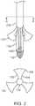
- Figure 2illustrates some embodiments of a delivery system.
- the delivery systemincludes catheter 100 and projections 132.
- catheter 100includes outer sheath 200.
- catheter 100includes capsule 120.
- catheter 100includes tip 110 disposed at an end of the catheter 100.
- outer sheath 200is configured to move or retract proximally thereby exposing a projection 132.
- outer sheath 200is configured to move or retract proximally thereby exposing multiple projections 132.
- outer sheath 200is configured to be actuated to expose a projection 132.
- the projection 132 or projections 132 or portions thereofare configured to automatically rotate, flex, bend, and/or spring outward from inner sheath 130 and/or capsule 120.
- a projection 132is configured to move away from capsule 120 when outer sheath 200 is removed from at least a portion of catheter 100.
- a projection 132is configured to move away from capsule 120 when outer sheath 200 is removed from at least a portion of inner sheath 130.
- capsule 120when outer sheath 200 is retracted proximally the capsule 120 remains in the same position. In some embodiments when capsule 120 remains in the same position medical device 400 which may be contained in capsule 120 remains in a collapsed state.
- At least one projection 132when outer sheath 200 is retracted a proximal distance at least one projection 132 is exposed and rotates, flexes, bends, and/or springs outwardly away from catheter 100. In some embodiments when outer sheath 200 is retracted proximally an additional distance at least one other projection 132 will rotate, flex, bend, and/or spring outward away from catheter 100. In some embodiments when outer sheath 200 is retracted a proximal distance, at least one projection 132 is exposed and rotates, flexes, bends, and/or springs outwardly away from capsule 120. In some embodiments when outer sheath 200 is retracted an additional proximal distance at least one other projection 132 will rotate, flex, bend, and/or spring outward away from capsule 120.
- the three projections 132are disposed radially. In some embodiments the projections 132 are disposed with equal distance between the projections 132. In some embodiments the projections 132 are disposed with non-equal distance between the projections 132.
- each projection 132extends from a portion of inner sheath 130.
- projections 132are made of varying shapes.
- projections 132include an arm portion 134.
- arm portion 134includes a portion of projection 132 proximate the inner sheath 130.
- projection 132includes a feeler portion 136.
- feeler portion 136is disposed adjacent arm portion 134.
- feeler portion 136is disposed adjacent arm portion 134, which is disposed adjacent inner sheath 130.
- feeler portion 136is distal inner sheath 130.
- projections 132are configured to be rotatable by manipulating catheter 100. In some embodiments projections 132 are configured to be rotatable by manipulating inner sheath 130. By rotating a projection 132 a person can position the medical device 400 or a prosthetic heart valve 500 within a patient 600.
- Section view AA of Figure 2illustrates the potential ability of multiple projections 132 to rotate either clockwise or counterclockwise, as needed, to position medical device 400 or prosthetic heart valve 500.
- the projections 132can aid in positioning a medical device 400 or a prosthetic heart valve 500.
- capsule 120is moved such that prosthetic heart valve 500 can be deployed.
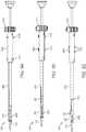
- Figure 3illustrates a prosthetic heart valve 500 being disposed on catheter 100.
- Catheter 100may include tip 110 and capsule 120.
- Capsule 120may be configured such that it can be retracted proximally up into outer sheath 200.
- Capsule 120may be configured such that it can be retracted proximally away from tip 110. In some embodiments the retraction of capsule 120 up into outer sheath 200 will allow prosthetic heart valve 500 to expand to an expanded state.
- prosthetic heart valve 500may be disposed on capsule 120. In some embodiments prosthetic heart valves 500 may be disposed in capsule 120.
- the projections 132may be comprised of any suitable material that can be introduced into a subject. This would include, but is not limited to, metals, plastics, polymers, a biocompatible material, biological material, and any other suitable material known to a person of ordinary skill in the art.
- a projection 132 or projections 132may have various shapes and profiles.
- Projection 132may comprise one material or multiple materials.
- Projection 132may comprise one piece or multiple pieces. In some embodiments the multiple pieces comprising projection 132 may be joined, attached, or coupled to each other.
- Projection 132may be solid or may be an outline formed into a desired shape.
- Projection 132may comprise an aperture or apertures in the solid.
- the outline of projection 132may also define one or more apertures.
- the solid or outline shapemay be formed from wire, such as nitinol, other shape memory metals, or an alloy,
- the solid or outline shapemay be formed from a plastic or a polymer.
- the solid or outline shapemay be formed from another biocompatible material.
- Projection 132may comprise a leaf, petal, elongate, tab, asymmetric, or other suitable shape.
- Figure 4Aillustrates some embodiments.
- a projection 132may comprise an arm portion 134.
- a projection 132may comprise a feeler portion 136.
- a projection 132may comprise an arm portion 134 and a feeler portion 136.
- the arm portion of 134may have different lengths for each side of the arm portion.
- the arm portion of 134may have two different lengths for each edge of the arm portion 134. As can be seen in Figure 4A the length of the left side or left edge of the projection 132 is shorter than the right side or edge of the projection 132.
- a projection 132may be asymmetric, In some embodiments a projection 132 may be symmetric. In some embodiments the side of a projection 132 may comprise an arc portion. In some embodiments the projection 132 may comprise a substantially straight portion and an arc portion on one side or edge. In some embodiments a projection 132 may have a side or edge that is substantially straight portion, an arc portion, and another substantially straight portion of the projection 132. In some embodiments the arm portion 134 can have different shapes for each side of one projection 132.
- the projection 132can have different shapes for each side or edge. In some embodiments the projection 132 may have a circular profile.
- each projection 132may include an arm portion 134 and a feeler portion 136.
- the feeler portion 136may comprise an arc section, a flat section, or a substantially straight section
- the feeler portion 136 of projection 132may include a section shaped similar to the shape of a sinus 116 in a heart .
- the feeler portion 136may be asymmetric.
- the feeler portion 136may be symmetric.
- the arm portion 134may be asymmetric.
- the arm portion 134may be symmetric.
- a projection 132may include an arm portion 134 comprised of substantially straight sections.
- the arm portion 134may include edges that are substantially parallel to one another for at least some length of the arm portion 134. In some embodiments the edges of arm portion 134 may not be substantially parallel.
- feeler portion 136can have a varying width.
- arm portion 134can have a varying width.
- feeler portion 136may have a width different from arm portion 134.
- feeler portion 136may be narrower than arm portion 134.
- feeler portion 136may be wider than arm portion 134.
- the width of the feeler portion 136 at one pointmay be greater than the width of the arm portion 134 at one point.
- the width of the feeler portion 136 at every pointmay be greater than the width of the arm portion 134 at every point.
- the width of feeler portion 136may be less than the width of arm portion 134.
- the width of feeler portion 136may be more than double the width of arm portion 134.
- the width of the feeler portion 136 at the widest pointmay be more than double the width of an arm portion 134 at its narrowest point.
- the distal end of feeler portion 136may be substantially straight. In some embodiments the distal end of feeler portion 136 may be an arc. In some embodiments the distal end of feeler portion 136 may be not straight.
- the arm portion 134can be of varying width along at least a portion of the length of arm portion 134.
- the feeler portion 136may include protrusions or extensions.
- the feeler portion 136may include one or more protrusions.
- the feeler portion 136may include an indentation 138.
- feeler portion 136may comprise a channel.
- feeler portion 136may comprise a notch.
- the feeler portion 136may include multiple indentations 138. In some embodiments the feeler portion 136 may include multiple channels. In some embodiments the feeler portion 136 may include multiple notches.
- the indentation 138may be less than a width of the arm portion 134. In some embodiments the indentation 138 may be less than every width of the arm portion 134. In some embodiments the indentation 138 may be greater than or equal to a width of the arm portion of 134. In some embodiments the indentation 138 may be greater than or equal to every width of the arm portion 134.
- the profile of feeler portion 136may be symmetric. In some embodiments the feeler portion 136 may be symmetric, including the indentation 138. In some embodiments the feeler portion may be symmetric about a line in the center of arm portion 134. In some embodiment the feeler portion 136 may be symmetric, as illustrated by Figure 4D . In some embodiments, the arm portion 134 may be symmetric, as illustrated in Figure 4B . In some embodiments the feeler portion 136 may have a symmetric profile. In some embodiments the feeler portion 136 may be asymmetric. In some embodiments the feeler portion 136 may be asymmetric, including the indentation 138. In some embodiments the indentation 138 may be asymmetric. In some embodiments the indentation 138 may be symmetric. In some embodiments the indentation 138 may be symmetric. In some embodiments the indentation 138 may be symmetric.
- the projection 132 including a feeler portion 136 and indentation portion 138may be configured such that the indentation 138 is configured to align the delivery system with a native commissure 612.
- indentation 138is configured such that the shape of indentation 138 is similar to a native commissural sinus 616. In some embodiments the indentation 138 is configured to have a shape different from a native commissural sinus 616. In some embodiments the indentation 138 may extend partially into the feeler portion 136. In some embodiments the indentation 138 may extend up to approximately half the length of the feeler portion 136. In some embodiments the indentation 138 may extend through the entire feeler portion 136. In some embodiments the indentation 138 can extend from the distal edge of the feeler portion 136 up into the arm portion 134. In some embodiments the indentation 138 stops before arm portion 134. In some embodiments the feeler portion may be configured to be shaped similar to a native commissural sinus 616.
- the projection 132is configured to provide tactile feedback regarding the location of a native commissure 612. In some embodiments the projection 132 is configured to provide tactile feedback regarding the location of a native commissural sinus 616. In some embodiments the projection 132 is configured to provide tactile feedback regarding the location of a native valve 614. In some embodiments the projection 132 is configured to provide tactile feedback regarding the location of a patient's heart 610.
- the projection 132may be symmetric. In some embodiments the projection 132 may be asymmetric.
- the feeler portion 136is arc shaped. In some embodiments the feeler portion 136 has an indentation 138 along the distal edge. In some embodiments the feeler portion 136 is wider than the arm portion 134. In some embodiments the feeler portion 136 is narrower than the arm portion 134. In some embodiments the feeler portion 136 has indentations 138 along the distal edge.
- the projection 132is configured to be a hybrid or combination projection 132. In some embodiments the projection 132 is configured to have an arc shaped distal edge. In some embodiments the distal edge of a projection 132 is configured such that it is shaped to help align the delivery system within the native commissural sinus 616 of a patient's heart 610. In some embodiments the projection 132 has an indentation 138 to help provide tactile aid to the physician. In some embodiments the projection 132 is configured to allow for tactile feedback regarding the native commissural sinus 616 or native commissure 612. In some embodiments the projection 132 is configured to allow for tactile feedback regarding the native commissural sinus 616 and native commissure 612. In some embodiments the projection 132 is configured to allow for tactile feedback regarding the native valve 614. In some embodiments the projection 132 is configured to allow for tactile feedback regarding the patient's heart 610.
- Figures 5A-5Eillustrate some embodiments of the invention.
- the delivery systemincludes a catheter 100, an outer sheath 200, and handle 300.
- the delivery systemmay be configured to receive either or both of a medical device 400 and a prosthetic heart valve 500.
- catheter 100includes a tip 110, a capsule 120, and inner sheath 130.
- tip 100is adjacent capsule 120.
- capsule 120is adjacent inner sheath 130.
- tip 110is substantially pointed and narrow.
- tip 110has at least one portion of similar cross-sectional area along its length.
- tip 110has a varying cross-sectional area along its length.
- tip 110is adjacent capsule 120.
- the cross-sectional area of tip 110increases from its distal most point to a point proximate capsule 120.
- tip 110 and capsule 120may be one integral part. In some embodiments tip 110 and capsule 120 may be two separate parts that are adjacent to one another. In some embodiments tip 110, capsule 120, inner sheath 130 may be one integral part. In some embodiments tip 110, capsule 120, and inner sheath 130 may all be separate parts. In some embodiments tip 110, capsule 120, and inner sheath 130 may be proximate one another.
- tip 110is proximate capsule 120.
- capsule 120is proximate to inner sheath 130.
- capsule 120is proximate to outer sheath 200.
- inner sheath 130proximate or adjacent to handle 300.
- outer sheath 200is proximate or adjacent handle 300.
- outer sheath 200is connected to handle 300. In some embodiments outer sheath 200 is coupled to handle 300. In some embodiments outer sheath 200 is joined to handle 300.
- outer sheath 200 and handle 300are an integral part. In some embodiments outer sheath 200 and handle 300 are separate parts.
- handle 300comprises an actuator 310.
- outer sheath 200is adjacent to handle 300.
- actuator 310is disposed on an end of handle 300.
- actuator 310is disposed on an end of handle 300 proximate outer sheath 200.
- actuator 310is disposed on an end of handle 300 distal outer sheath 200.
- actuator 310is disposed at a point along the length of the handle 300.
- handle 300includes varying cross-sectional areas. In some embodiments handle 300 a portion having a smaller cross-sectional area and a portion having a larger cross-sectional area. In some embodiments the portion having a larger cross-sectional area of handle 300 is disposed distal the end adjacent outer sheath 200. In some embodiments the portion having a larger cross-sectional area of handle 300 is disposed proximate the end adjacent outer sheath 200. In some embodiments handle 300 comprises a lumen through which a part or parts of the delivery system can pass through. In some embodiments handle 300 comprises a lumen through which a part or parts of the delivery system can move. In some embodiments the catheter 100 is threaded through the handle 300.
- a portion of outer sheath 200is surrounded by handle 300. In some embodiments a portion of outer sheath 200 is contained within handle 300. In some embodiments a portion of inner sheath 130 is surrounded by handle 300. In some embodiments a portion of inner sheath 130 is contained in handle 300.
- handle 300is a cylindrical shape. In some embodiments handle 300 has a cross-section similar to a square. In some embodiments handle 300 has a cross-section similar to a rectangle, triangle, oval, or other geometric shape.
- handle 300comprises one or more actuators 310. In some embodiments handle 300 comprises two or more actuators 310. In some embodiments handle 300 comprises actuators at different positions along a length of handle 300. In some embodiments actuators 310 are disposed at different points along the length of handle 300. In some embodiments one actuator is disposed on a portion of handle 300 distal from tip 110. In some embodiments an actuator 310 is disposed on a portion of handle 300 proximate tip 110. In some embodiments one actuator 310 is disposed on a portion of handle 300 proximate tip 110, while another actuator is disposed on a portion of handle 300 more distal tip 110. In some embodiments where three actuators 310 may be employed, each actuator may be disposed on a different portion of handle 300.
- two actuators 310are disposed on a portion of handle 300 with a first cross-sectional area. In some embodiments a third actuator 310 may be disposed on a portion of handle 300 with a second cross-sectional area.
- actuators 310may be actuated by a person. In some embodiments actuators 310 may be actuated using only one hand. In some embodiments actuators 310 may be actuated using one finger. In some embodiments when actuators are actuated outer sheath 200 is retracted, as illustrated in figure 5B . In some embodiments after actuator 310 is actuated outer sheath 200 is partially retracted. In some embodiments after actuator 310 is actuated outer sheath 200 is partially retracted and projection 132 or projections 132 may be exposed. In some embodiments actuators 310 may retract outer sheath 200.
- actuator 310may advance inner sheath 130. In some embodiments actuator 310 may advance projections 132. In some embodiments once projections 132 are advanced projections 132 begin to rotate radially outward. In some embodiments once projections 132 are advanced, projections 132 begin to flare outward. In some embodiments once projections 132 are advanced, projections 132 begin to move outward. In some embodiments when inner sheath 130 is advanced, projections 132 begin to open.
- projections 132may have a rectangular cross-sectional area. In some embodiments projections 132 may have a non-rectangular cross-sectional area. In some embodiments projections 132 may have a circular cross-sectional area. In some embodiments projections 132 may have an oval cross-sectional area. In some embodiments projections 132 may be curved on one side. In some embodiments projections 132 may be curved on two sides.
- projections 132can be advanced to at least partially cover capsule 120. In some embodiments projections 132 may be advanced to at least partially overlap with capsule 120. In some embodiments projections 132 are moved forward over at least a portion of capsule 120. In some embodiments after projections 132 are advanced capsule 120 is opened or retracted enough to anchor or position medical device 400. In some embodiments after projections 132 are advanced, capsule 120 is opened or retracted enough to anchor or position prosthetic heart valve 500. In some embodiments actuator 310 may retract support arms or projections 132 from the capsule area.
- the delivery system including catheter 100is configured to align a prosthetic heart valve 500 inside a patient's heart 610.
- one projection 132may be may be coupled or attached to inner sheath 130.
- multiple projections 132may be coupled or attached to inner sheath 130.
- projection 132includes an arm portion 134 or a feeler portion 136. In some embodiments projection 132 includes an arm portion 134 and a feeler portion 136. In some embodiments feeler portion 136 further comprises an indentation 138.
- projections 132are aligned with elements of medical device 400. In some embodiments projections 132 are aligned with elements of medical device 400 when projections 132 are proximate medical device 400. In some embodiments projections 132 are aligned with elements of medical device 400. In some embodiments projections 132 are aligned with elements of medical device 400 when projections 132 are disposed on or in capsule 120.
- projections 132are aligned with elements of prosthetic heart valve 500. In some embodiments portions of projection 132 are aligned with certain portions of prosthetic heart valve 500. In some embodiments projections 132 are aligned with two commissural posts 510 of prosthetic heart valve 500.
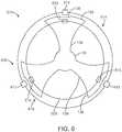
- a patient heart 610may comprise native commissures 612, native valves 614, and native commissural sinuses 616. As can be seen in Figure 6 , when projections 132 are extended toward a patient's heart 610 the projections 132 are configured to aid in positioning the prosthetic heart valve 500 inside the patient's heart 610.
- the projections 132may be aligned with one or more commissural posts 510. In some embodiments the projections 132 may be aligned with one or more native commissures 612. In some embodiments, as illustrated by Figure 6A , projections 132 may include feeler portions 136 configured such that feeler portions 136 are similar in shape to a portion of patient's heart 610. Projections 132 may include feeler portions 136 configured such that feeler portions 136 are substantially similar in shape to a portion of the native valves 614 or a portion of a native commissural sinus 616. In some embodiments a projection 132 comprises a feeler portion 136 and an indentation 138.
- indentation 138is configured to receive a native commissure 612.
- shape of indentation 138provides for specific alignment of prosthetic heart valve 500 within patient heart 610.
- the delivery systemmay include multiple projections 132 configured to align the prosthetic heart valve 500 with patient heart 610.
- the delivery systemmay only comprise one projection 132 for aligning prosthetic heart valve 500 with patient's heart 610.
- a patientmay require a valve-in-valve medical procedure wherein a second prosthetic heart valve is positioned and implanted within a previously implanted prosthetic heart valve.
- the previously implanted prosthetic heart valvemay be, for example, a surgical valve, a tissue valve, a mechanical valve, a suture-less surgical valve, a stented valve, a non-stented valve, a transcatheter valve, a balloon expandable valve, a mechanically expandable valve a, and/or a self-expandable valve.
- patient heart 610may comprise one or more prosthetic heart valves previously implanted during one or more previous medical procedures.
- projections 132may be configured to aid in positioning medical device 400 and/or prosthetic heart valve 500 inside patient heart 610 comprising a prosthetic valve implanted in a previous medical procedure. In some embodiments projections 132 may be aligned with one or more portions of a previously implanted prosthetic heart valve such as one or more commissural posts of a previously implanted prosthetic heart valve.
- Projections 132may include feeler portions 136 configured such that feeler portions 136 are substantially similar in shape to one or more portions of a previously implanted prosthetic heart valve.
- a projection 132comprises a feeler portion 136 and an indentation 138.
- indentation 138is configured to receive a prosthetic heart valve commissure.
- shape of indentation 138provides for specific alignment of medical device 400 and/or prosthetic heart valve 500 within a prosthetic heart valve within patient heart 610.
- the delivery systemmay include multiple projections 132 configured to align medical device 400 and/or prosthetic heart valve 500 with a prosthetic heart valve previously implanted in patient heart 610. In some embodiments the delivery system may only comprise one projection 132 for aligning medical device 400 and/or prosthetic heart valve 500 with a prosthetic heart valve previously implanted in patient heart 610. In some embodiments there may be exactly two or three projections 132 for aligning medical device 400 and/or prosthetic heart valve 500 with a prosthetic heart valve previously implanted in patient heart 610. In some embodiments there may be more than three projections 132 for aligning medical device 400 and/or prosthetic heart valve 500 with a prosthetic heart valve previously implanted in patient heart 610.
- a patientmay require a medical procedure wherein a prosthetic heart valve is positioned and implanted within a previously implanted medical device such as a prosthetic heart valve repair device including, for example an annuloplasty ring or annuloplasty band device.
- a patientmay require a valve-in-ring medical procedure.
- the previously implanted prosthetic heart valve repair devicemay be, for example, an annuloplasty device, an annuloplasty ring device, an annuloplasty band device, a prosthetic heart valve support device, and/or a prosthetic heart valve anchor device.
- patient heart 610may comprise one or more prosthetic heart valve repair devices previously implanted during one or more previous medical procedures.
- projections 132may be configured to aid in positioning medical device 400 and/or prosthetic heart valve 500 inside patient heart 610 comprising a prosthetic valve repair device implanted in a previous medical procedure. In some embodiments projections 132 may be aligned with one or more portions of a previously implanted prosthetic heart valve repair device. Projections 132 may include feeler portions 136 configured such that feeler portions 136 are substantially similar in shape to one or more portions of a previously implanted prosthetic heart valve repair device.
- the shape of projection 132may provide for specific alignment of medical device 400 and/or prosthetic heart valve 500 within a prosthetic heart valve repair device within patient heart 610.
- the delivery systemmay include multiple projections 132 configured to align medical device 400 and/or prosthetic heart valve 500 with a prosthetic heart valve repair device previously implanted in patient heart 610.
- the delivery systemmay only comprise one projection 132 for aligning medical device 400 and/or prosthetic heart valve 500 with a prosthetic heart valve repair device previously implanted in patient heart 610.
- projections 132may have shapes different from one another, In embodiments with multiple projections 132, one projection 132 may have a curved distal edge similar to a native commissural sinus 616 in a patient's heart 610. Another projection 132 may have a distal edge that is substantially straight. Another projection 132 may have a distal edge that includes indentation 138.
- the profile of projections 132may vary even when projections 132 may be part of the same delivery system.
- the shape of projections 132may vary even when projections 132 may be part of the same delivery system.
- a first projection 132may have a shape different from a second projection 132.
- a first projection 132may have a shape different from a second projection 132 and different from a third projection.
- a second projection 132may have a shape different from a third projection 132.
- all projections 132have a shape different from every other projection 132.
- one projection 132comprises a feeler portion 136 that is wider than a feeler portion 136 on a second projection 132.
- a first projection 132may have an arm portion 134 that is wider than an arm portion 134 on a second projection 132.
Landscapes
- Health & Medical Sciences (AREA)
- Cardiology (AREA)
- Life Sciences & Earth Sciences (AREA)
- Engineering & Computer Science (AREA)
- Veterinary Medicine (AREA)
- Biomedical Technology (AREA)
- Heart & Thoracic Surgery (AREA)
- Animal Behavior & Ethology (AREA)
- General Health & Medical Sciences (AREA)
- Public Health (AREA)
- Vascular Medicine (AREA)
- Transplantation (AREA)
- Oral & Maxillofacial Surgery (AREA)
- Biophysics (AREA)
- Mechanical Engineering (AREA)
- Physics & Mathematics (AREA)
- Molecular Biology (AREA)
- Surgery (AREA)
- Medical Informatics (AREA)
- Pathology (AREA)
- Anesthesiology (AREA)
- Pulmonology (AREA)
- Hematology (AREA)
- Prostheses (AREA)
Description
- In many medical procedures, a delivery system is used to place a medical device, such as a prosthetic heart valve, in a patient. Often a prosthetic heart valve is disposed on a delivery system in order to be placed in a patient. One type of delivery system is a catheter, which can deliver the prosthetic heart valve via a transfemoral procedure. As part of this procedure the prosthetic heart valve must be positioned in the patient. Visualization techniques such as fluoroscopy may be used to locate the native heart valve components and align the prosthetic heart valve in the patient, but can require substantial contrast medium exposure to the patient, increased risk, and can be difficult.
- Further, some current prosthetic heart valves employ projections or arms to aid in retention of the prosthetic heart valve. However, these control, engagement, or support arms increase the profile of the prosthetic heart valve making the overall profile of the prosthetic heart valve and delivery system larger. Other current prosthetic heart valves are not configured to include control arms and physicians are unable to utilize the benefits of these control arms in procedures involving such prosthetic heart valves.
US 2010/0191326 A1 teaches an apparatus and method for implanting collapsible / expandable prosthetic hearth valves.WO 2009/024859 describes stent-valves for valve replacement and associated methods and systems for surgery.WO 2012/177942 A2 describes prosthetic heart valve devices and associated systems and methods.US 2013/079872 A1 is in regard to a distal tip assembly for a heart valve delivery catheter.US 2011/301702 A1 is in regard to a transcatheter delivery system and method with controlled expansion and contraction of a prosthetic heart valve.WO 2011/130093 A1 is in regard to a transcatheter prosthetic heart valve delivery device with funnel recapturing feature and method.US 5,683,451 Adescribes an apparatus and methods for deployment release of intraluminal prostheses.US 2008/132989 A1 describes device and methods for controlling expandable prostheses during deployment.US 2007/0021819 A1 describes an apparatus and methods for locating an ostium of a vessel.- Disclosed herein is a system for delivering a medical device in accordance with claim 1.
- The delivery system comprises a projection or a support arm structure. Employing a projection or support arm on the delivery system provides advantages. Having a projection on the delivery system as opposed to on a medical device or a prosthetic heart valve will lower the profile of the prosthetic heart valve and delivery system. This lower profile allows for better control and manipulation by a physician. In addition, employing projections on a delivery system allows for advantages when used with medical devices or prosthetic heart valves that do not or cannot employ similar projections. For example, some heart valves do not or cannot use control arms for various reasons. Having projections on the delivery system permits the delivery system to be used with these prosthetic heart valves while also providing advantages associated with such projections. For example, the projections on the delivery system may provide tactile feedback in positioning the heart valve. As another example, the projections may be configured to aid in aligning a prosthetic heart valve with a native heart valve.
- The support arm structure or projections can locate the prosthetic heart valve relative to a native heart valve. The support arm structure provides a way to give tactile feedback of the location of the prosthetic heart valve as well as the native valve and surrounding area to a physician or surgeon. Thus, the support arm structure provides an advantage to the physician in implanting prosthetic heart valves and other devices. Another potential advantage of this type of support arm structure is to limit the amount of fluoroscopy used or contrast medium required to place a prosthetic heart valve within the patient.
- The support arm structure or projection is part of a delivery system. This delivery system is catheter-based. In some embodiments any type of prosthetic heart valve could be placed in or on a delivery system that includes support arms or projections. These prosthetic valve types would include aortic, mitral, or other valve types, including balloon expandable, mechanically expandable, self-expandable, or surgical suture-less valves. Any prosthetic valve type could be used in conjunction with the delivery system that comprises a support, engagement, or control arm or projection.
- The support arms or projections can provide mechanical or tactile feedback. In some embodiments this projection or support arm structure can provide enough feedback to limit visualization techniques required to correctly position the prosthetic heart valve inside the patient's heart. In some embodiments the projection or support arm structure may provide enough feedback and information regarding the position of the prosthetic heart valves, such that no visualization technique may be required. In some embodiments using the projection without requiring visualization techniques will be advantageous. For example, these visualization techniques may be unavailable, be potentially dangerous to the patient, or foregoing such visualization may reduce associated risks. In some embodiments these projections or support arm structures will minimize the amount of contrast medium used in examining the patient and will reduce the subsequent associated renal problems associated with contrast medium exposure.
- The projection or support arm structure will provide feedback regarding orientation. In some embodiments the projection will aid in rotational positioning of the prosthetic heart valve. In some embodiments the projection will aid in axial positioning of the prosthetic heart valve.
- The delivery device includes a catheter and the catheter includes a tip, a capsule adjacent the tip, and an inner sheath adjacent the capsule.
- The inner sheath is disposed along a longitudinal axis, an outer sheath is disposed along the longitudinal axis and connected to a handle, and the handle further comprising an actuator.
- The inner sheath comprises projections distal the handle. The actuator is configured to actuate the outer sheath. In some embodiments the capsule is configured to receive a prosthetic heart valve. The outer sheath is configured to move along the longitudinal axis to expose the projections. In some embodiments the projections are configured to open outward from the longitudinal axis.
- In some embodiments the projections are asymmetric.
- In some embodiments each projection is uniquely shaped.
- In some embodiments the projections are configured to evenly space from each other when they are rotated outward.
- Each projection comprises an arm portion and a feeler portion, the feeler portion having a proximal and distal end.
- In some embodiments the feeler portion has a substantially straight distal end.
- The feeler portion comprises protrusions extending away from the arm portion.
- The feeler portion comprises a curved end on the distal most end, and wherein the feeler portion further comprises a notch.
- In some embodiments the feeler portion is symmetric.
- In some embodiments the feeler portion is asymmetric.
- To aid in the understanding of the invention, there exists a method of delivering a prosthetic heart valve, the method including advancing a delivery system into a patient's heart having native commissures, the delivery system including a catheter.
- The catheter comprises a tip, a capsule adjacent the tip, an inner sheath adjacent the capsule, and the inner sheath being disposed along a longitudinal axis, an outer sheath configured to move along the longitudinal axis and connected to a handle.
- The handle further comprises an actuator, the inner sheath has a proximal end and a distal end, and the inner sheath being disposed along a longitudinal axis.
- In some embodiments the inner sheath comprises projections proximal the capsule. In some embodiments the projections are configured to rotate outward from the longitudinal axis. The actuator is configured to actuate the outer sheath. The capsule contains a prosthetic heart valve configured to collapse to a collapsible state and expand to an expanded state.
- The method, disclosed to aid in the understanding of the invention, includes
retracting the outer sheath. In some embodiments the method includes advancing the projections proximate the capsule. In some embodiments the method includes causing the projections to rotate outward from the longitudinal axis. The method, disclosed to aid in the understanding of the invention, includes expanding the prosthetic heart valve to an expanded state. The method, disclosed to aid in the understanding of the invention, includes anchoring the prosthetic heart valve in the patient's heart. - The projections further comprise an arm portion and a feeler portion, the method (disclosed to aid in the understanding of the invention) further comprising using the projections to position the prosthetic heart valve.
- The method, disclosed to aid in the understanding of the invention, further comprises using the projections to position the prosthetic heart valve by aligning a portion of the feeler portion of one projection with a portion of the patient's heart.
- The feeler portion of one projection further comprises a notch, the method (disclosed to aid in the understanding of the invention) further comprising using the projections to position the prosthetic heart valve by aligning the notch of the projection with a portion of the patient's heart.
- In some embodiments the feeler portion of one projection further comprises a channel, the method, disclosed to aid in the understanding of the invention, further comprising using the projections to position the prosthetic heart valve by aligning the channel of one projection with a portion of the patient's heart.
- The method, disclosed to aid in the understanding of the invention, further comprising generating a fluoroscopic image positioning the prosthetic heart valve based on the position of one projection relative to a portion of the patient's heart.
- An assembly for delivering a prosthetic heart valve is disclosed. The assembly comprises a tip, a capsule adjacent the tip, an inner sheath adjacent the capsule, the inner sheath being disposed along a longitudinal axis, an outer sheath being disposed along the longitudinal axis, a handle coupled to the outer sheath, and the handle further comprising an actuator.
- The inner sheath comprises a projection distal the handle. The actuator is configured to actuate the outer sheath. The capsule is configured to receive a prosthetic heart valve. The outer sheath is configured to expose the projection. The projection is configured to extend away from the longitudinal axis.
- The projection further comprises an indentation on the distal end.
- In some embodiments the projection is configured to be positioned relative to a native commissure by using fluoroscopic imaging.
- In some embodiments the projection further comprises an asymmetric shape.
- The embodiments and related concepts will be more fully understood from the following detailed description of the embodiments thereof.
Figures 1-3 illustrate a delivery system in accordance with some embodiments;Figures 4A-4D illustrate a portion of a delivery system in accordance with some embodiments;Figures 5A-5E illustrate a delivery system in accordance with some embodiments; andFigure 6 illustrates a delivery system relative to a patient's heart in accordance with some embodiments.- While the disclosure refers to illustrative embodiments for particular embodiments, it should be understood that the disclosure is not limited thereto. Those skilled in the art with access to this disclosure will recognize additional modifications, embodiments, and embodiments within the scope of this disclosure and additional fields, in which the disclosed examples could be applied. Therefore, the following detailed description is not meant to be limiting. Further, it is understood that the apparatus and methods described below can be implemented in many different embodiments of hardware. Any actual hardware described is not meant to be limiting. The operation and behavior of the apparatus and methods presented are described with the understanding that modifications and variations of the embodiments are possible.
- References to "one embodiment," "an embodiment," "some embodiments," "in certain embodiments," etc..., indicate that the embodiment described may include a particular feature, structure, or characteristic, but every embodiment may not necessarily include the particular feature, structure, or characteristic. Moreover, such phrases are not necessarily referring to the same embodiment. Further, when a particular feature, structure, or characteristic is described in connection with an embodiment, it is submitted that it is within the knowledge of one skilled in the art to affect such feature, structure, or characteristic in connection with other embodiments whether or not explicitly described.
- The delivery system includes a catheter-based delivery system. In some
embodiments catheter 100 will include multiple elements. In someembodiments catheter 100 includes adistal tip 110, acapsule 120, andinner sheath 130.Inner sheath 130 includesmultiple projections 132.Projections 132 include anarm portion 134.Projections 132 include afeeler portion 136.Projections 132 include anindentation 138 as part offeeler portion 136. In someembodiments projections 132 are separate frominner sheath 130. - In some
embodiments catheter 100 may includeprojections 132 that are connected toinner sheath 130. In someembodiments catheter 100 may includeprojections 132 that are integral withinner sheath 130. In some embodimentsinner sheath 130 may include twoprojections 132. In some embodimentsinner sheath 130 may include more than twoprojections 132. - The delivery system includes an
outer sheath 200. The delivery system includes aproximal handle 300. Handle 300 includes anactuator 310. - The delivery system is configured to receive a
medical device 400. In some embodiments the delivery system includescatheter 100 configured such thatmedical device 400 can be contained incapsule 120. In some embodiments the delivery system includescatheter 100 configured such thatmedical device 400 can be disposed oncapsule 120. In some embodimentsmedical device 400 may comprise a prosthetic heart valve and/or a prosthetic heart valve repair device. - The delivery system includes
catheter 100 configured such thatprosthetic heart valve 500 can be contained incapsule 120. In some embodiments the delivery system includescatheter 100 configured such thatprosthetic heart valve 500 can be disposed oncapsule 120. - In some embodiments
prosthetic heart valve 500 may include two or three or morecommissural posts 510. In some embodimentsprosthetic heart valve 500 may include one, two, or morecommissural posts 510. - The
catheter 100 comprises atip 110, acapsule 120, andinner sheath 130. In some embodiments the tip is disposed at the distal end ofcatheter 100. Thecapsule 120 is adjacent thetip 110. Theinner sheath 130 is adjacent thecapsule 120. In someembodiments capsule 120 may comprise a split capsule having two or more portions. - The
inner sheath 130 is disposed along a longitudinal axis. Theouter sheath 200 is disposed along a longitudinal axis. In some embodiments theouter sheath 200 is disposed along the same longitudinal axis as theinner sheath 130. - The
outer sheath 200 is connected to ahandle 300. In some embodiments theinner sheath 130 comprisesprojections 132 distal thehandle 300. In some embodiments actuator 310 is configured to actuateouter sheath 200. In some embodimentsouter sheath 200 is configured to move along a longitudinal axis to expose theprojections 132. Theprojections 132 are configured to open outward from the longitudinal axis. In some embodiments theactuator 310 is configured to actuate any part of the delivery system. - In some embodiments the delivery system can be used to deliver a
prosthetic heart valve 500 into a patient'sheart 610. In some embodiments apatient 600 has aheart 610 that includesnative commissures 612, anative valve 614, and nativecommissural sinuses 616. - In some embodiments a method of delivering a
prosthetic heart valve 500 includes advancingcatheter 100 into a patient'sheart 600 that has anative commissure 612. In some embodiments thecapsule 120 is configured to contain aprosthetic heart valve 500. - In some embodiments the
prosthetic heart valve 500 is configured to collapse to a collapsed state. In some embodiments theprosthetic heart valve 500 is configured to expand to an expanded state. In some embodiments the method of delivering aprosthetic heart valve 500 further includes retracting theouter sheath 200 after thecatheter 100 has been advanced into a patient'sheart 610. In some embodiments the method further includes advancing theprojection 132 orprojections 132 proximate thecapsule 120. in some embodiments the method further includes causing aprojection 132 to rotate outward from the longitudinal axis and away from thecatheter 100. In some embodiments the method further includes expanding theprosthetic heart valve 500 to an expanded state. In some embodiments the method further includes anchoring theprosthetic heart valve 500 in a patient'sheart 610. Figure 1 illustrates a delivery device in accordance with some embodiments.Figure 1 illustrates acatheter 100. In someembodiments catheter 100 includestip 110,capsule 120, andinner sheath 130. In some embodiments,tip 110 may comprise different geometries including a narrowed end portion, as shown inFigure 1 , a blunt tip, or a purely cylindrical tip.Tip 110 can vary in length.- In some
embodiments capsule 120 may vary in length. In someembodiments capsule 120 may be shorter or longer thantip 110. In someembodiments capsule 120 may be wider or narrower thantip 110. In someembodiments capsule 120 may be wider or narrower in diameter, circumference, or perimeter than any or all portions oftip 110. In some embodiments tip 110 may comprisecapsule 120. In some embodiments tip 110 may comprise a distal portion ofcapsule 120. - In some embodiments, the capsule portion may be configured to contain a
medical device 400 as illustrated inFigure 1 . In someembodiments capsule 120 may be configured to contain aprosthetic heart valve 500. In some embodiments amedical device 400 can be disposed oncapsule 120. In some embodiments amedical device 400 can be disposed incapsule 120. In some embodiments amedical device 400 can be disposed on another portion ofcatheter 100. In some embodimentsprosthetic heart valve 500 may be configured to be disposed oncapsule 120. In some embodimentsprosthetic heart valve 500 may be configured to be disposed incapsule 120. In some embodimentsprosthetic heart valve 500 may be configured to be disposed on another portion ofcatheter 100. - In some
embodiments capsule 120 can also have the same characteristics related toinner sheath 130. In someembodiments capsule 120 may be shorter or longer thaninner sheath 130. In someembodiments capsule 120 may be wider or narrowerinner sheath 130. In someembodiments capsule 120 may be wider or narrower in diameter, circumference, or perimeter than any or all portions ofinner sheath 130. - In some embodiments, the delivery system may comprise an
outer sheath 200 as illustrated inFigure 1 . In some embodimentsouter sheath 200 may be configured to extend andcover tip 100. In some embodimentsouter sheath 200 may be configured to extend andcover capsule 120. In some embodimentsouter sheath 200 may be configured to extend and coverinner sheath 130. In some embodimentsouter sheath 200 may be configured to extend andsurround tip 100. In some embodimentsouter sheath 200 may be configured to extend andsurround capsule 120. In some embodimentsouter sheath 200 may be configured to extend and surroundinner sheath 130. In some embodimentsouter sheath 200 may comprisecapsule 120. In some embodimentsouter sheath 200 may comprise a proximal portion ofcapsule 120. - In some embodiments
outer sheath 200 may be configured to cover or surround aprojection 132 disposed oninner sheath 130. In some embodimentsouter sheath 200 may be configured to cover or surround aprojection 132 that is an integral part ofinner sheath 130. In some embodimentsouter sheath 200 may be configured to cover or surround aprojection 132 that is positioned betweeninner sheath 130 andouter sheath 200. Figure 2 illustrates some embodiments of a delivery system. In some embodiments the delivery system includescatheter 100 andprojections 132. In someembodiments catheter 100 includesouter sheath 200. In someembodiments catheter 100 includescapsule 120. In someembodiments catheter 100 includestip 110 disposed at an end of thecatheter 100. In some embodimentsouter sheath 200 is configured to move or retract proximally thereby exposing aprojection 132. In some embodimentsouter sheath 200 is configured to move or retract proximally thereby exposingmultiple projections 132. In some embodimentsouter sheath 200 is configured to be actuated to expose aprojection 132.- In some embodiments when
outer sheath 200 is retracted proximally theprojection 132 orprojections 132 or portions thereof are configured to automatically rotate, flex, bend, and/or spring outward frominner sheath 130 and/orcapsule 120. In some embodiments aprojection 132 is configured to move away fromcapsule 120 whenouter sheath 200 is removed from at least a portion ofcatheter 100. In some embodiments aprojection 132 is configured to move away fromcapsule 120 whenouter sheath 200 is removed from at least a portion ofinner sheath 130. - In some embodiments when
outer sheath 200 is retracted proximally thecapsule 120 remains in the same position. In some embodiments whencapsule 120 remains in the same positionmedical device 400 which may be contained incapsule 120 remains in a collapsed state. - In some embodiments when
outer sheath 200 is retracted a proximal distance at least oneprojection 132 is exposed and rotates, flexes, bends, and/or springs outwardly away fromcatheter 100. In some embodiments whenouter sheath 200 is retracted proximally an additional distance at least oneother projection 132 will rotate, flex, bend, and/or spring outward away fromcatheter 100. In some embodiments whenouter sheath 200 is retracted a proximal distance, at least oneprojection 132 is exposed and rotates, flexes, bends, and/or springs outwardly away fromcapsule 120. In some embodiments whenouter sheath 200 is retracted an additional proximal distance at least oneother projection 132 will rotate, flex, bend, and/or spring outward away fromcapsule 120. - In some embodiments as illustrated in section view A-A of
Figure 2 , the threeprojections 132 are disposed radially. In some embodiments theprojections 132 are disposed with equal distance between theprojections 132. In some embodiments theprojections 132 are disposed with non-equal distance between theprojections 132. - In some embodiments each
projection 132 extends from a portion ofinner sheath 130. - In some
embodiments projections 132 are made of varying shapes. In someembodiments projections 132 include anarm portion 134. In some embodiments armportion 134 includes a portion ofprojection 132 proximate theinner sheath 130. In someembodiments projection 132 includes afeeler portion 136. In some embodiments feelerportion 136 is disposedadjacent arm portion 134. In some embodiments feelerportion 136 is disposedadjacent arm portion 134, which is disposed adjacentinner sheath 130. In some embodiments feelerportion 136 is distalinner sheath 130. - In some
embodiments projections 132 are configured to be rotatable by manipulatingcatheter 100. In someembodiments projections 132 are configured to be rotatable by manipulatinginner sheath 130. By rotating a projection 132 a person can position themedical device 400 or aprosthetic heart valve 500 within apatient 600. - Section view AA of
Figure 2 illustrates the potential ability ofmultiple projections 132 to rotate either clockwise or counterclockwise, as needed, to positionmedical device 400 orprosthetic heart valve 500. - in some embodiments, as illustrated in
Figure 3 , theprojections 132 can aid in positioning amedical device 400 or aprosthetic heart valve 500. In someembodiments capsule 120 is moved such thatprosthetic heart valve 500 can be deployed.Figure 3 illustrates aprosthetic heart valve 500 being disposed oncatheter 100.Catheter 100 may includetip 110 andcapsule 120.Capsule 120 may be configured such that it can be retracted proximally up intoouter sheath 200.Capsule 120 may be configured such that it can be retracted proximally away fromtip 110. In some embodiments the retraction ofcapsule 120 up intoouter sheath 200 will allowprosthetic heart valve 500 to expand to an expanded state. In some embodiments the retraction ofcapsule 120 along with some actuation will allowprosthetic heart valve 500 to expand to an expanded state. In some embodimentsprosthetic heart valves 500 may be disposed oncapsule 120. In some embodimentsprosthetic heart valves 500 may be disposed incapsule 120. - The
projections 132 may be comprised of any suitable material that can be introduced into a subject. This would include, but is not limited to, metals, plastics, polymers, a biocompatible material, biological material, and any other suitable material known to a person of ordinary skill in the art. - As illustrated in
Figures 4A-4D aprojection 132 orprojections 132 may have various shapes and profiles.Projection 132 may comprise one material or multiple materials.Projection 132 may comprise one piece or multiple pieces. In some embodiments the multiplepieces comprising projection 132 may be joined, attached, or coupled to each other.Projection 132 may be solid or may be an outline formed into a desired shape.Projection 132 may comprise an aperture or apertures in the solid. The outline ofprojection 132 may also define one or more apertures. In some embodiments the solid or outline shape may be formed from wire, such as nitinol, other shape memory metals, or an alloy, In some embodiments the solid or outline shape may be formed from a plastic or a polymer. In some embodiments the solid or outline shape may be formed from another biocompatible material.Projection 132 may comprise a leaf, petal, elongate, tab, asymmetric, or other suitable shape. Figure 4A illustrates some embodiments. In some embodiments aprojection 132 may comprise anarm portion 134. In some embodiments aprojection 132 may comprise afeeler portion 136. In some embodiments aprojection 132 may comprise anarm portion 134 and afeeler portion 136. In some embodiments the arm portion of 134 may have different lengths for each side of the arm portion. In some embodiments the arm portion of 134 may have two different lengths for each edge of thearm portion 134. As can be seen inFigure 4A the length of the left side or left edge of theprojection 132 is shorter than the right side or edge of theprojection 132.- In some embodiments a
projection 132 may be asymmetric, In some embodiments aprojection 132 may be symmetric. In some embodiments the side of aprojection 132 may comprise an arc portion. In some embodiments theprojection 132 may comprise a substantially straight portion and an arc portion on one side or edge. In some embodiments aprojection 132 may have a side or edge that is substantially straight portion, an arc portion, and another substantially straight portion of theprojection 132. In some embodiments thearm portion 134 can have different shapes for each side of oneprojection 132. - In some embodiments the
projection 132 can have different shapes for each side or edge. In some embodiments theprojection 132 may have a circular profile. - In some embodiments comprising
multiple projections 132, eachprojection 132 may include anarm portion 134 and afeeler portion 136. In some embodiments thefeeler portion 136 may comprise an arc section, a flat section, or a substantially straight section In some embodiments thefeeler portion 136 ofprojection 132 may include a section shaped similar to the shape of a sinus 116 in a heart . In some embodiments thefeeler portion 136 may be asymmetric. In some embodiments thefeeler portion 136 may be symmetric. In some embodiments thearm portion 134 may be asymmetric. In some embodiments thearm portion 134 may be symmetric. - In some embodiments, as shown in
Figure 4B , aprojection 132 may include anarm portion 134 comprised of substantially straight sections. In some embodiments thearm portion 134 may include edges that are substantially parallel to one another for at least some length of thearm portion 134. In some embodiments the edges ofarm portion 134 may not be substantially parallel. - In some embodiments feeler
portion 136 can have a varying width. In some embodiments armportion 134 can have a varying width. In some embodiments feelerportion 136 may have a width different fromarm portion 134. In some embodiments feelerportion 136 may be narrower thanarm portion 134. In some embodiments feelerportion 136 may be wider thanarm portion 134. In some embodiments the width of thefeeler portion 136 at one point may be greater than the width of thearm portion 134 at one point. In some embodiments the width of thefeeler portion 136 at every point may be greater than the width of thearm portion 134 at every point. In some embodiments the width offeeler portion 136 may be less than the width ofarm portion 134. In some embodiments the width offeeler portion 136 may be more than double the width ofarm portion 134. In some embodiments the width of thefeeler portion 136 at the widest point may be more than double the width of anarm portion 134 at its narrowest point. - In some embodiments the distal end of
feeler portion 136 may be substantially straight. In some embodiments the distal end offeeler portion 136 may be an arc. In some embodiments the distal end offeeler portion 136 may be not straight. - In some embodiments, the
arm portion 134 can be of varying width along at least a portion of the length ofarm portion 134. In some embodiments thefeeler portion 136 may include protrusions or extensions. In some embodiments thefeeler portion 136 may include one or more protrusions. In some embodiments thefeeler portion 136 may include anindentation 138. In some embodiments feelerportion 136 may comprise a channel. In some embodiments feelerportion 136 may comprise a notch. - In some embodiments the
feeler portion 136 may includemultiple indentations 138. In some embodiments thefeeler portion 136 may include multiple channels. In some embodiments thefeeler portion 136 may include multiple notches. - In some embodiments the
indentation 138 may be less than a width of thearm portion 134. In some embodiments theindentation 138 may be less than every width of thearm portion 134. In some embodiments theindentation 138 may be greater than or equal to a width of the arm portion of 134. In some embodiments theindentation 138 may be greater than or equal to every width of thearm portion 134. - In some embodiments the profile of
feeler portion 136 may be symmetric. In some embodiments thefeeler portion 136 may be symmetric, including theindentation 138. In some embodiments the feeler portion may be symmetric about a line in the center ofarm portion 134. In some embodiment thefeeler portion 136 may be symmetric, as illustrated byFigure 4D . In some embodiments, thearm portion 134 may be symmetric, as illustrated inFigure 4B . In some embodiments thefeeler portion 136 may have a symmetric profile. In some embodiments thefeeler portion 136 may be asymmetric. In some embodiments thefeeler portion 136 may be asymmetric, including theindentation 138. In some embodiments theindentation 138 may be asymmetric. In some embodiments theindentation 138 may be symmetric. - In some embodiments the
projection 132 including afeeler portion 136 andindentation portion 138 may be configured such that theindentation 138 is configured to align the delivery system with anative commissure 612. - In some embodiments indentation 138 is configured such that the shape of
indentation 138 is similar to a nativecommissural sinus 616. In some embodiments theindentation 138 is configured to have a shape different from a nativecommissural sinus 616. In some embodiments theindentation 138 may extend partially into thefeeler portion 136. In some embodiments theindentation 138 may extend up to approximately half the length of thefeeler portion 136. In some embodiments theindentation 138 may extend through theentire feeler portion 136. In some embodiments theindentation 138 can extend from the distal edge of thefeeler portion 136 up into thearm portion 134. In some embodiments theindentation 138 stops beforearm portion 134. In some embodiments the feeler portion may be configured to be shaped similar to a nativecommissural sinus 616. - In some embodiments the
projection 132 is configured to provide tactile feedback regarding the location of anative commissure 612. In some embodiments theprojection 132 is configured to provide tactile feedback regarding the location of a nativecommissural sinus 616. In some embodiments theprojection 132 is configured to provide tactile feedback regarding the location of anative valve 614. In some embodiments theprojection 132 is configured to provide tactile feedback regarding the location of a patient'sheart 610. - In some embodiments, as illustrated in
Figure 4D , theprojection 132 may be symmetric. In some embodiments theprojection 132 may be asymmetric. - In some embodiments the
feeler portion 136 is arc shaped. In some embodiments thefeeler portion 136 has anindentation 138 along the distal edge. In some embodiments thefeeler portion 136 is wider than thearm portion 134. In some embodiments thefeeler portion 136 is narrower than thearm portion 134. In some embodiments thefeeler portion 136 hasindentations 138 along the distal edge. - In some embodiments the
projection 132 is configured to be a hybrid orcombination projection 132. In some embodiments theprojection 132 is configured to have an arc shaped distal edge. In some embodiments the distal edge of aprojection 132 is configured such that it is shaped to help align the delivery system within the nativecommissural sinus 616 of a patient'sheart 610. In some embodiments theprojection 132 has anindentation 138 to help provide tactile aid to the physician. In some embodiments theprojection 132 is configured to allow for tactile feedback regarding the nativecommissural sinus 616 ornative commissure 612. In some embodiments theprojection 132 is configured to allow for tactile feedback regarding the nativecommissural sinus 616 andnative commissure 612. In some embodiments theprojection 132 is configured to allow for tactile feedback regarding thenative valve 614. In some embodiments theprojection 132 is configured to allow for tactile feedback regarding the patient'sheart 610. Figures 5A-5E illustrate some embodiments of the invention. In some embodiments the delivery system includes acatheter 100, anouter sheath 200, and handle 300. In some embodiments the delivery system may be configured to receive either or both of amedical device 400 and aprosthetic heart valve 500.- In some
embodiments catheter 100 includes atip 110, acapsule 120, andinner sheath 130. In some embodiments tip 100 isadjacent capsule 120. In someembodiments capsule 120 is adjacentinner sheath 130. In some embodiments tip 110 is substantially pointed and narrow. In some embodiments tip 110 has at least one portion of similar cross-sectional area along its length. In other embodiments tip 110 has a varying cross-sectional area along its length. In some embodiments tip 110 isadjacent capsule 120. In some embodiments the cross-sectional area oftip 110 increases from its distal most point to a pointproximate capsule 120. - In some embodiments tip 110 and
capsule 120 may be one integral part. In some embodiments tip 110 andcapsule 120 may be two separate parts that are adjacent to one another. In some embodiments tip 110,capsule 120,inner sheath 130 may be one integral part. In some embodiments tip 110,capsule 120, andinner sheath 130 may all be separate parts. In some embodiments tip 110,capsule 120, andinner sheath 130 may be proximate one another. - In some embodiments tip 110 is
proximate capsule 120. In someembodiments capsule 120 is proximate toinner sheath 130. In someembodiments capsule 120 is proximate toouter sheath 200. In some embodimentsinner sheath 130 proximate or adjacent to handle 300. In some embodimentsouter sheath 200 is proximate oradjacent handle 300. - In some embodiments
outer sheath 200 is connected to handle 300. In some embodimentsouter sheath 200 is coupled to handle 300. In some embodimentsouter sheath 200 is joined to handle 300. - In some embodiments
outer sheath 200 and handle 300 are an integral part. In some embodimentsouter sheath 200 and handle 300 are separate parts. - In some embodiments handle 300 comprises an
actuator 310. In some embodimentsouter sheath 200 is adjacent to handle 300. In some embodiments actuator 310 is disposed on an end ofhandle 300. In some embodiments actuator 310 is disposed on an end ofhandle 300 proximateouter sheath 200. In some embodiments actuator 310 is disposed on an end ofhandle 300 distalouter sheath 200. In some embodiments actuator 310 is disposed at a point along the length of thehandle 300. - In some embodiments handle 300 includes varying cross-sectional areas. In some embodiments handle 300 a portion having a smaller cross-sectional area and a portion having a larger cross-sectional area. In some embodiments the portion having a larger cross-sectional area of
handle 300 is disposed distal the end adjacentouter sheath 200. In some embodiments the portion having a larger cross-sectional area ofhandle 300 is disposed proximate the end adjacentouter sheath 200. In some embodiments handle 300 comprises a lumen through which a part or parts of the delivery system can pass through. In some embodiments handle 300 comprises a lumen through which a part or parts of the delivery system can move. In some embodiments thecatheter 100 is threaded through thehandle 300. - In some embodiments a portion of
outer sheath 200 is surrounded byhandle 300. In some embodiments a portion ofouter sheath 200 is contained withinhandle 300. In some embodiments a portion ofinner sheath 130 is surrounded byhandle 300. In some embodiments a portion ofinner sheath 130 is contained inhandle 300. - In some embodiments handle 300 is a cylindrical shape. In some embodiments handle 300 has a cross-section similar to a square. In some embodiments handle 300 has a cross-section similar to a rectangle, triangle, oval, or other geometric shape.
- In some embodiments handle 300 comprises one or
more actuators 310. In some embodiments handle 300 comprises two ormore actuators 310. In some embodiments handle 300 comprises actuators at different positions along a length ofhandle 300. In some embodiments actuators 310 are disposed at different points along the length ofhandle 300. In some embodiments one actuator is disposed on a portion ofhandle 300 distal fromtip 110. In some embodiments anactuator 310 is disposed on a portion ofhandle 300proximate tip 110. In some embodiments oneactuator 310 is disposed on a portion ofhandle 300proximate tip 110, while another actuator is disposed on a portion ofhandle 300 moredistal tip 110. In some embodiments where threeactuators 310 may be employed, each actuator may be disposed on a different portion ofhandle 300. - In some embodiments two
actuators 310 are disposed on a portion ofhandle 300 with a first cross-sectional area. In some embodiments athird actuator 310 may be disposed on a portion ofhandle 300 with a second cross-sectional area. - In some embodiments actuators 310 may be actuated by a person. In some embodiments actuators 310 may be actuated using only one hand. In some embodiments actuators 310 may be actuated using one finger. In some embodiments when actuators are actuated
outer sheath 200 is retracted, as illustrated infigure 5B . In some embodiments afteractuator 310 is actuatedouter sheath 200 is partially retracted. In some embodiments afteractuator 310 is actuatedouter sheath 200 is partially retracted andprojection 132 orprojections 132 may be exposed. In some embodiments actuators 310 may retractouter sheath 200. - In some embodiments actuator 310 may advance
inner sheath 130. In some embodiments actuator 310 may advanceprojections 132. In some embodiments onceprojections 132 areadvanced projections 132 begin to rotate radially outward. In some embodiments onceprojections 132 are advanced,projections 132 begin to flare outward. In some embodiments onceprojections 132 are advanced,projections 132 begin to move outward. In some embodiments wheninner sheath 130 is advanced,projections 132 begin to open. - In some
embodiments projections 132 may have a rectangular cross-sectional area. In someembodiments projections 132 may have a non-rectangular cross-sectional area. In someembodiments projections 132 may have a circular cross-sectional area. In someembodiments projections 132 may have an oval cross-sectional area. In someembodiments projections 132 may be curved on one side. In someembodiments projections 132 may be curved on two sides. - In some
embodiments projections 132 can be advanced to at least partially covercapsule 120. In someembodiments projections 132 may be advanced to at least partially overlap withcapsule 120. In someembodiments projections 132 are moved forward over at least a portion ofcapsule 120. In some embodiments afterprojections 132 areadvanced capsule 120 is opened or retracted enough to anchor or positionmedical device 400. In some embodiments afterprojections 132 are advanced,capsule 120 is opened or retracted enough to anchor or positionprosthetic heart valve 500. In some embodiments actuator 310 may retract support arms orprojections 132 from the capsule area. - In some embodiments the delivery
system including catheter 100 is configured to align aprosthetic heart valve 500 inside a patient'sheart 610. In some embodiments oneprojection 132 may be may be coupled or attached toinner sheath 130. In some embodimentsmultiple projections 132 may be coupled or attached toinner sheath 130. - In some
embodiments projection 132 includes anarm portion 134 or afeeler portion 136. In someembodiments projection 132 includes anarm portion 134 and afeeler portion 136. In some embodiments feelerportion 136 further comprises anindentation 138. - In some
embodiments projections 132 are aligned with elements ofmedical device 400. In someembodiments projections 132 are aligned with elements ofmedical device 400 whenprojections 132 are proximatemedical device 400. In someembodiments projections 132 are aligned with elements ofmedical device 400. In someembodiments projections 132 are aligned with elements ofmedical device 400 whenprojections 132 are disposed on or incapsule 120. - ln some
embodiments projections 132 are aligned with elements ofprosthetic heart valve 500. In some embodiments portions ofprojection 132 are aligned with certain portions ofprosthetic heart valve 500. In someembodiments projections 132 are aligned with twocommissural posts 510 ofprosthetic heart valve 500. - A
patient heart 610 may comprisenative commissures 612,native valves 614, and nativecommissural sinuses 616. As can be seen inFigure 6 , whenprojections 132 are extended toward a patient'sheart 610 theprojections 132 are configured to aid in positioning theprosthetic heart valve 500 inside the patient'sheart 610. - In some embodiments, as illustrated in
Figure 6 , theprojections 132 may be aligned with one or morecommissural posts 510. In some embodiments theprojections 132 may be aligned with one or morenative commissures 612. In some embodiments, as illustrated byFigure 6A ,projections 132 may includefeeler portions 136 configured such thatfeeler portions 136 are similar in shape to a portion of patient'sheart 610.Projections 132 may includefeeler portions 136 configured such thatfeeler portions 136 are substantially similar in shape to a portion of thenative valves 614 or a portion of a nativecommissural sinus 616. In some embodiments aprojection 132 comprises afeeler portion 136 and anindentation 138. In some embodiments indentation 138 is configured to receive anative commissure 612. In some embodiments the shape ofindentation 138 provides for specific alignment ofprosthetic heart valve 500 withinpatient heart 610. As illustrated inFigure 6 , the delivery system may includemultiple projections 132 configured to align theprosthetic heart valve 500 withpatient heart 610. In some embodiments, the delivery system may only comprise oneprojection 132 for aligningprosthetic heart valve 500 with patient'sheart 610. In some embodiments there may be exactly twoprojections 132 for aligningprosthetic heart valve 500 with patient'sheart 610. - In some embodiments a patient may require a valve-in-valve medical procedure wherein a second prosthetic heart valve is positioned and implanted within a previously implanted prosthetic heart valve. In some embodiments the previously implanted prosthetic heart valve may be, for example, a surgical valve, a tissue valve, a mechanical valve, a suture-less surgical valve, a stented valve, a non-stented valve, a transcatheter valve, a balloon expandable valve, a mechanically expandable valve a, and/or a self-expandable valve. In some embodiments
patient heart 610 may comprise one or more prosthetic heart valves previously implanted during one or more previous medical procedures. In someembodiments projections 132 may be configured to aid in positioningmedical device 400 and/orprosthetic heart valve 500 insidepatient heart 610 comprising a prosthetic valve implanted in a previous medical procedure. In someembodiments projections 132 may be aligned with one or more portions of a previously implanted prosthetic heart valve such as one or more commissural posts of a previously implanted prosthetic heart valve. Projections 132 may includefeeler portions 136 configured such thatfeeler portions 136 are substantially similar in shape to one or more portions of a previously implanted prosthetic heart valve. In some embodiments aprojection 132 comprises afeeler portion 136 and anindentation 138. In some embodiments indentation 138 is configured to receive a prosthetic heart valve commissure. In some embodiments the shape ofindentation 138 provides for specific alignment ofmedical device 400 and/orprosthetic heart valve 500 within a prosthetic heart valve withinpatient heart 610.- In some embodiments the delivery system may include
multiple projections 132 configured to alignmedical device 400 and/orprosthetic heart valve 500 with a prosthetic heart valve previously implanted inpatient heart 610. In some embodiments the delivery system may only comprise oneprojection 132 for aligningmedical device 400 and/orprosthetic heart valve 500 with a prosthetic heart valve previously implanted inpatient heart 610. In some embodiments there may be exactly two or threeprojections 132 for aligningmedical device 400 and/orprosthetic heart valve 500 with a prosthetic heart valve previously implanted inpatient heart 610. In some embodiments there may be more than threeprojections 132 for aligningmedical device 400 and/orprosthetic heart valve 500 with a prosthetic heart valve previously implanted inpatient heart 610. - In some embodiments a patient may require a medical procedure wherein a prosthetic heart valve is positioned and implanted within a previously implanted medical device such as a prosthetic heart valve repair device including, for example an annuloplasty ring or annuloplasty band device. In some embodiments a patient may require a valve-in-ring medical procedure, In some embodiments the previously implanted prosthetic heart valve repair device may be, for example, an annuloplasty device, an annuloplasty ring device, an annuloplasty band device, a prosthetic heart valve support device, and/or a prosthetic heart valve anchor device. In some embodiments
patient heart 610 may comprise one or more prosthetic heart valve repair devices previously implanted during one or more previous medical procedures. - In some
embodiments projections 132 may be configured to aid in positioningmedical device 400 and/orprosthetic heart valve 500 insidepatient heart 610 comprising a prosthetic valve repair device implanted in a previous medical procedure. In someembodiments projections 132 may be aligned with one or more portions of a previously implanted prosthetic heart valve repair device.Projections 132 may includefeeler portions 136 configured such thatfeeler portions 136 are substantially similar in shape to one or more portions of a previously implanted prosthetic heart valve repair device. - In some embodiments the shape of
projection 132 may provide for specific alignment ofmedical device 400 and/orprosthetic heart valve 500 within a prosthetic heart valve repair device withinpatient heart 610. In some embodiments the delivery system may includemultiple projections 132 configured to alignmedical device 400 and/orprosthetic heart valve 500 with a prosthetic heart valve repair device previously implanted inpatient heart 610. In some embodiments the delivery system may only comprise oneprojection 132 for aligningmedical device 400 and/orprosthetic heart valve 500 with a prosthetic heart valve repair device previously implanted inpatient heart 610. In some embodiments there may be exactly two or threeprojections 132 for aligningmedical device 400 and/orprosthetic heart valve 500 with a prosthetic heart valve repair device previously implanted inpatient heart 610. - In some
embodiments projections 132 may have shapes different from one another, In embodiments withmultiple projections 132, oneprojection 132 may have a curved distal edge similar to a nativecommissural sinus 616 in a patient'sheart 610. Anotherprojection 132 may have a distal edge that is substantially straight. Anotherprojection 132 may have a distal edge that includesindentation 138. - In some embodiments the profile of
projections 132 may vary even whenprojections 132 may be part of the same delivery system. In some embodiments the shape ofprojections 132 may vary even whenprojections 132 may be part of the same delivery system. In some embodiments, afirst projection 132 may have a shape different from asecond projection 132. In some embodiments, afirst projection 132 may have a shape different from asecond projection 132 and different from a third projection. In some embodiments, asecond projection 132 may have a shape different from athird projection 132. In some embodiments, allprojections 132 have a shape different from everyother projection 132. In some embodiments oneprojection 132 comprises afeeler portion 136 that is wider than afeeler portion 136 on asecond projection 132. In some embodiments afirst projection 132 may have anarm portion 134 that is wider than anarm portion 134 on asecond projection 132. - The foregoing description has been presented for purposes of illustration and description. It is not intended to be exhaustive or to limit the precise embodiments disclosed. Other modifications and variations may be possible in light of the above teachings. The embodiments and examples were chosen and described in order to best explain the principles of the embodiments and their practical application, and to thereby enable others skilled in the art to best utilize the various embodiments with modifications as are suited to the particular use contemplated. By applying knowledge within the skill of the art, others can readily modify and/or adapt for various applications such specific embodiments, without undue experimentation, without departing from the general concept.
Claims (11)
- A system for delivering a prosthetic heart valve, the system comprising:
a catheter (100), the catheter (100) comprising:a tip (110);a capsule (120) adjacent the tip (110);an inner sheath (130) adjacent the capsule (120);the inner sheath (130) being disposed along a longitudinal axis;an outer sheath (200) disposed along the longitudinal axis and connected to a handle (300) ; andthe handle (300) further comprising an actuator (310) ;wherein the inner sheath (130) comprises projections (132) distal the handle (300),wherein the actuator (310) is configured to actuate the outer sheath (200),wherein the capsule (120) is configured to receive a prosthetic heart valve (400),wherein the outer sheath (200) is configured to move along the longitudinal axis to expose the projections (132),wherein the projections (132) are configured to open outward from the longitudinal axis;wherein each projection (132) comprises an arm portion (134) and a feeler portion (136), the feeler portion (136) having a proximal and distal end wherein the feeler portion (136) comprises a curved end on the distal most end;and wherein the feeler portion (136) further comprises a notch or an indentation. - The system of claim 1, wherein the projections (132) are asymmetric.
- The system of claim 1, wherein each projection (132) is uniquely shaped.
- The system of claim 1, wherein the projections (132) are configured to evenly space from each other when they are rotated outward.
- The system of claim 1, wherein the feeler portion (136) has a substantially straight distal end.
- The system of claim 1, wherein the feeler portion (136) comprises protrusions extending away from the arm portion (134).
- The system of claim 1, wherein the feeler portion (136) is symmetric.
- The system of claim 1, wherein the feeler portion (136) is asymmetric.
- The system of claim 1, wherein the projection comprises a shape made from wire.
- The system of claim 1, wherein the projections (132) are configured to be positioned relative to a native commissure (612) by using fluoroscopic imaging.
- The system of claim 1, wherein the projections (132) further comprise an asymmetric shape.
Applications Claiming Priority (2)
| Application Number | Priority Date | Filing Date | Title |
|---|---|---|---|
| US13/939,612US9237948B2 (en) | 2013-07-11 | 2013-07-11 | Delivery system with projections |
| PCT/US2014/045294WO2015006140A1 (en) | 2013-07-11 | 2014-07-02 | Delivery system with projections |
Publications (2)
| Publication Number | Publication Date |
|---|---|
| EP3019123A1 EP3019123A1 (en) | 2016-05-18 |
| EP3019123B1true EP3019123B1 (en) | 2019-10-02 |
Family
ID=51220908
Family Applications (1)
| Application Number | Title | Priority Date | Filing Date |
|---|---|---|---|
| EP14742436.0AActiveEP3019123B1 (en) | 2013-07-11 | 2014-07-02 | Delivery system with projections |
Country Status (3)
| Country | Link |
|---|---|
| US (1) | US9237948B2 (en) |
| EP (1) | EP3019123B1 (en) |
| WO (1) | WO2015006140A1 (en) |
Cited By (34)
| Publication number | Priority date | Publication date | Assignee | Title |
|---|---|---|---|---|
| US10595994B1 (en) | 2018-09-20 | 2020-03-24 | Vdyne, Llc | Side-delivered transcatheter heart valve replacement |
| US10856984B2 (en) | 2017-08-25 | 2020-12-08 | Neovasc Tiara Inc. | Sequentially deployed transcatheter mitral valve prosthesis |
| US10940001B2 (en) | 2012-05-30 | 2021-03-09 | Neovasc Tiara Inc. | Methods and apparatus for loading a prosthesis onto a delivery system |
| US11071627B2 (en) | 2018-10-18 | 2021-07-27 | Vdyne, Inc. | Orthogonally delivered transcatheter heart valve frame for valve in valve prosthesis |
| US11076956B2 (en) | 2019-03-14 | 2021-08-03 | Vdyne, Inc. | Proximal, distal, and anterior anchoring tabs for side-delivered transcatheter mitral valve prosthesis |
| US11109969B2 (en) | 2018-10-22 | 2021-09-07 | Vdyne, Inc. | Guidewire delivery of transcatheter heart valve |
| US11166814B2 (en) | 2019-08-20 | 2021-11-09 | Vdyne, Inc. | Delivery and retrieval devices and methods for side-deliverable transcatheter prosthetic valves |
| US11173027B2 (en) | 2019-03-14 | 2021-11-16 | Vdyne, Inc. | Side-deliverable transcatheter prosthetic valves and methods for delivering and anchoring the same |
| US11185409B2 (en) | 2019-01-26 | 2021-11-30 | Vdyne, Inc. | Collapsible inner flow control component for side-delivered transcatheter heart valve prosthesis |
| US11202706B2 (en) | 2019-05-04 | 2021-12-21 | Vdyne, Inc. | Cinch device and method for deployment of a side-delivered prosthetic heart valve in a native annulus |
| US11234813B2 (en) | 2020-01-17 | 2022-02-01 | Vdyne, Inc. | Ventricular stability elements for side-deliverable prosthetic heart valves and methods of delivery |
| US11253359B2 (en) | 2018-12-20 | 2022-02-22 | Vdyne, Inc. | Proximal tab for side-delivered transcatheter heart valves and methods of delivery |
| US11273033B2 (en) | 2018-09-20 | 2022-03-15 | Vdyne, Inc. | Side-delivered transcatheter heart valve replacement |
| US11273032B2 (en) | 2019-01-26 | 2022-03-15 | Vdyne, Inc. | Collapsible inner flow control component for side-deliverable transcatheter heart valve prosthesis |
| US11278437B2 (en) | 2018-12-08 | 2022-03-22 | Vdyne, Inc. | Compression capable annular frames for side delivery of transcatheter heart valve replacement |
| US11298227B2 (en) | 2019-03-05 | 2022-04-12 | Vdyne, Inc. | Tricuspid regurgitation control devices for orthogonal transcatheter heart valve prosthesis |
| US11311376B2 (en) | 2019-06-20 | 2022-04-26 | Neovase Tiara Inc. | Low profile prosthetic mitral valve |
| US11331186B2 (en) | 2019-08-26 | 2022-05-17 | Vdyne, Inc. | Side-deliverable transcatheter prosthetic valves and methods for delivering and anchoring the same |
| US11344413B2 (en) | 2018-09-20 | 2022-05-31 | Vdyne, Inc. | Transcatheter deliverable prosthetic heart valves and methods of delivery |
| US11357622B2 (en) | 2016-01-29 | 2022-06-14 | Neovase Tiara Inc. | Prosthetic valve for avoiding obstruction of outflow |
| US11389291B2 (en) | 2013-04-04 | 2022-07-19 | Neovase Tiara Inc. | Methods and apparatus for delivering a prosthetic valve to a beating heart |
| US11413139B2 (en) | 2011-11-23 | 2022-08-16 | Neovasc Tiara Inc. | Sequentially deployed transcatheter mitral valve prosthesis |
| US11419720B2 (en) | 2010-05-05 | 2022-08-23 | Neovasc Tiara Inc. | Transcatheter mitral valve prosthesis |
| US11464631B2 (en) | 2016-11-21 | 2022-10-11 | Neovasc Tiara Inc. | Methods and systems for rapid retraction of a transcatheter heart valve delivery system |
| US11491006B2 (en) | 2019-04-10 | 2022-11-08 | Neovasc Tiara Inc. | Prosthetic valve with natural blood flow |
| US11497602B2 (en) | 2012-02-14 | 2022-11-15 | Neovasc Tiara Inc. | Methods and apparatus for engaging a valve prosthesis with tissue |
| US11602429B2 (en) | 2019-04-01 | 2023-03-14 | Neovasc Tiara Inc. | Controllably deployable prosthetic valve |
| US11737872B2 (en) | 2018-11-08 | 2023-08-29 | Neovasc Tiara Inc. | Ventricular deployment of a transcatheter mitral valve prosthesis |
| US11779742B2 (en) | 2019-05-20 | 2023-10-10 | Neovasc Tiara Inc. | Introducer with hemostasis mechanism |
| US11786366B2 (en) | 2018-04-04 | 2023-10-17 | Vdyne, Inc. | Devices and methods for anchoring transcatheter heart valve |
| US11998447B2 (en) | 2019-03-08 | 2024-06-04 | Neovasc Tiara Inc. | Retrievable prosthesis delivery system |
| US12109111B2 (en) | 2015-12-15 | 2024-10-08 | Neovasc Tiara Inc. | Transseptal delivery system |
| US12186187B2 (en) | 2018-09-20 | 2025-01-07 | Vdyne, Inc. | Transcatheter deliverable prosthetic heart valves and methods of delivery |
| US12343256B2 (en) | 2019-01-10 | 2025-07-01 | Vdyne, Inc. | Anchor hook for side-delivery transcatheter heart valve prosthesis |
Families Citing this family (11)
| Publication number | Priority date | Publication date | Assignee | Title |
|---|---|---|---|---|
| US9730790B2 (en) | 2009-09-29 | 2017-08-15 | Edwards Lifesciences Cardiaq Llc | Replacement valve and method |
| US9681951B2 (en) | 2013-03-14 | 2017-06-20 | Edwards Lifesciences Cardiaq Llc | Prosthesis with outer skirt and anchors |
| US10245072B2 (en) | 2015-07-10 | 2019-04-02 | Medtronic, Inc. | Extravascular medical access tools having boring tip and methods of using such tools |
| US10758729B2 (en)* | 2015-10-01 | 2020-09-01 | Medtronic, Inc. | Interventional medical systems, catheters, and methods |
| US10350067B2 (en)* | 2015-10-26 | 2019-07-16 | Edwards Lifesciences Corporation | Implant delivery capsule |
| US10080888B2 (en) | 2015-11-16 | 2018-09-25 | Medtronic, Inc. | Interventional medical systems and associated methods |
| US10583007B2 (en) | 2015-12-02 | 2020-03-10 | Edwards Lifesciences Corporation | Suture deployment of prosthetic heart valve |
| US10555811B2 (en)* | 2016-01-13 | 2020-02-11 | Medtronic, Inc. | Delivery device for a stented prosthetic heart valve |
| US10667907B2 (en) | 2016-05-13 | 2020-06-02 | St. Jude Medical, Cardiology Division, Inc. | Systems and methods for device implantation |
| DE102017108521A1 (en)* | 2017-04-21 | 2018-10-25 | Biotronik Ag | Catheter device with rotatable distal tip |
| CN110730676B (en)* | 2017-06-15 | 2022-07-29 | 奥林巴斯株式会社 | Guiding tube |
Citations (10)
| Publication number | Priority date | Publication date | Assignee | Title |
|---|---|---|---|---|
| US5683451A (en)* | 1994-06-08 | 1997-11-04 | Cardiovascular Concepts, Inc. | Apparatus and methods for deployment release of intraluminal prostheses |
| WO2006005082A2 (en)* | 2004-06-28 | 2006-01-12 | Xtent, Inc. | Devices and methods for controlling expandable prostheses during deployment |
| US20070021819A1 (en)* | 2005-05-23 | 2007-01-25 | Jeff Krolik | Apparatus and Methods for Locating an Ostium of a Vessel |
| US20080132989A1 (en)* | 2004-06-28 | 2008-06-05 | Xtent, Inc. | Devices and methods for controlling expandable prostheses during deployment |
| US20080139915A1 (en)* | 2006-12-07 | 2008-06-12 | Medtronic Vascular, Inc. | Vascular Position Locating and/or Mapping Apparatus and Methods |
| WO2009024859A2 (en)* | 2007-08-21 | 2009-02-26 | Symetis Sa | Stent-valves for valve replacement and associated methods and systems for surgery |
| WO2011130093A1 (en)* | 2010-04-12 | 2011-10-20 | Medtronic Inc. | Transcatheter prosthetic heart valve delivery device with funnel recapturing feature and method |
| US20110301702A1 (en)* | 2010-06-02 | 2011-12-08 | Medtronic, Inc. | Transcatheter Delivery System and Method with Controlled Expansion and Contraction of Prosthetic Heart Valve |
| WO2012177942A2 (en)* | 2011-06-21 | 2012-12-27 | Hanson Gifford, Iii | Prosthetic heart valve devices and associated systems and methods |
| US20130079872A1 (en)* | 2011-09-28 | 2013-03-28 | Medtronic CV Luxembourg S.a.r.l. | Distal Tip Assembly for a Heart Valve Delivery Catheter |
Family Cites Families (14)
| Publication number | Priority date | Publication date | Assignee | Title |
|---|---|---|---|---|
| AU770243B2 (en) | 1999-04-09 | 2004-02-19 | Evalve, Inc. | Methods and apparatus for cardiac valve repair |
| CA2813136A1 (en) | 2004-02-27 | 2005-09-15 | Aortx, Inc. | Prosthetic heart valve delivery systems and methods |
| US8167932B2 (en) | 2005-10-18 | 2012-05-01 | Edwards Lifesciences Corporation | Heart valve delivery system with valve catheter |
| JP2009535128A (en) | 2006-04-29 | 2009-10-01 | アーバー・サージカル・テクノロジーズ・インコーポレイテッド | Multi-part prosthetic heart valve assembly and apparatus and method for delivering the same |
| US8585594B2 (en) | 2006-05-24 | 2013-11-19 | Phoenix Biomedical, Inc. | Methods of assessing inner surfaces of body lumens or organs |
| JP5248606B2 (en)* | 2007-06-26 | 2013-07-31 | セント ジュード メディカル インコーポレイテッド | Device for implanting a collapsible / expandable prosthetic heart valve |
| EP2679198B1 (en) | 2007-10-25 | 2021-03-24 | Symetis SA | Valved-stents and systems for delivery thereof |
| EP3912597A1 (en) | 2008-02-29 | 2021-11-24 | Edwards Lifesciences Corporation | Expandable member for deploying a prosthetic device |
| WO2010031060A1 (en) | 2008-09-15 | 2010-03-18 | Medtronic Ventor Technologies Ltd. | Prosthetic heart valve having identifiers for aiding in radiographic positioning |
| US20110251676A1 (en)* | 2010-04-12 | 2011-10-13 | Medtronic Vascular, Inc. | Sheath for Controlled Delivery of a Heart Valve Prosthesis |
| US8876892B2 (en) | 2010-04-21 | 2014-11-04 | Medtronic, Inc. | Prosthetic heart valve delivery system with spacing |
| US9326853B2 (en)* | 2010-07-23 | 2016-05-03 | Edwards Lifesciences Corporation | Retaining mechanisms for prosthetic valves |
| US9579197B2 (en) | 2010-12-15 | 2017-02-28 | Medtronic Vascular, Inc. | Systems and methods for positioning a heart valve using visual markers |
| EP2736450A1 (en) | 2011-07-28 | 2014-06-04 | St. Jude Medical, Inc. | Expandable radiopaque marker for transcatheter aortic valve implantation |
- 2013
- 2013-07-11USUS13/939,612patent/US9237948B2/enactiveActive
- 2014
- 2014-07-02EPEP14742436.0Apatent/EP3019123B1/enactiveActive
- 2014-07-02WOPCT/US2014/045294patent/WO2015006140A1/enactiveApplication Filing
Patent Citations (10)
| Publication number | Priority date | Publication date | Assignee | Title |
|---|---|---|---|---|
| US5683451A (en)* | 1994-06-08 | 1997-11-04 | Cardiovascular Concepts, Inc. | Apparatus and methods for deployment release of intraluminal prostheses |
| WO2006005082A2 (en)* | 2004-06-28 | 2006-01-12 | Xtent, Inc. | Devices and methods for controlling expandable prostheses during deployment |
| US20080132989A1 (en)* | 2004-06-28 | 2008-06-05 | Xtent, Inc. | Devices and methods for controlling expandable prostheses during deployment |
| US20070021819A1 (en)* | 2005-05-23 | 2007-01-25 | Jeff Krolik | Apparatus and Methods for Locating an Ostium of a Vessel |
| US20080139915A1 (en)* | 2006-12-07 | 2008-06-12 | Medtronic Vascular, Inc. | Vascular Position Locating and/or Mapping Apparatus and Methods |
| WO2009024859A2 (en)* | 2007-08-21 | 2009-02-26 | Symetis Sa | Stent-valves for valve replacement and associated methods and systems for surgery |
| WO2011130093A1 (en)* | 2010-04-12 | 2011-10-20 | Medtronic Inc. | Transcatheter prosthetic heart valve delivery device with funnel recapturing feature and method |
| US20110301702A1 (en)* | 2010-06-02 | 2011-12-08 | Medtronic, Inc. | Transcatheter Delivery System and Method with Controlled Expansion and Contraction of Prosthetic Heart Valve |
| WO2012177942A2 (en)* | 2011-06-21 | 2012-12-27 | Hanson Gifford, Iii | Prosthetic heart valve devices and associated systems and methods |
| US20130079872A1 (en)* | 2011-09-28 | 2013-03-28 | Medtronic CV Luxembourg S.a.r.l. | Distal Tip Assembly for a Heart Valve Delivery Catheter |
Cited By (44)
| Publication number | Priority date | Publication date | Assignee | Title |
|---|---|---|---|---|
| US11419720B2 (en) | 2010-05-05 | 2022-08-23 | Neovasc Tiara Inc. | Transcatheter mitral valve prosthesis |
| US12053369B2 (en) | 2011-11-23 | 2024-08-06 | Neovasc Tiara Inc. | Sequentially deployed transcatheter mitral valve prosthesis |
| US11413139B2 (en) | 2011-11-23 | 2022-08-16 | Neovasc Tiara Inc. | Sequentially deployed transcatheter mitral valve prosthesis |
| US12138159B2 (en) | 2012-02-14 | 2024-11-12 | Neovasc Tiara Inc. | Methods and apparatus for engaging a valve prosthesis with tissue |
| US11497602B2 (en) | 2012-02-14 | 2022-11-15 | Neovasc Tiara Inc. | Methods and apparatus for engaging a valve prosthesis with tissue |
| US11389294B2 (en) | 2012-05-30 | 2022-07-19 | Neovasc Tiara Inc. | Methods and apparatus for loading a prosthesis onto a delivery system |
| US10940001B2 (en) | 2012-05-30 | 2021-03-09 | Neovasc Tiara Inc. | Methods and apparatus for loading a prosthesis onto a delivery system |
| US11617650B2 (en) | 2012-05-30 | 2023-04-04 | Neovasc Tiara Inc. | Methods and apparatus for loading a prosthesis onto a delivery system |
| US11389291B2 (en) | 2013-04-04 | 2022-07-19 | Neovase Tiara Inc. | Methods and apparatus for delivering a prosthetic valve to a beating heart |
| US12109111B2 (en) | 2015-12-15 | 2024-10-08 | Neovasc Tiara Inc. | Transseptal delivery system |
| US12193932B2 (en) | 2016-01-29 | 2025-01-14 | Neovasc Tiara Inc. | Prosthetic valve for avoiding obstruction of outflow |
| US11357622B2 (en) | 2016-01-29 | 2022-06-14 | Neovase Tiara Inc. | Prosthetic valve for avoiding obstruction of outflow |
| US11464631B2 (en) | 2016-11-21 | 2022-10-11 | Neovasc Tiara Inc. | Methods and systems for rapid retraction of a transcatheter heart valve delivery system |
| US12201524B2 (en) | 2016-11-21 | 2025-01-21 | Neovasc Tiara Inc. | Methods and systems for rapid retraction of a transcatheter heart valve delivery system |
| US11793640B2 (en) | 2017-08-25 | 2023-10-24 | Neovasc Tiara Inc. | Sequentially deployed transcatheter mitral valve prosthesis |
| US10856984B2 (en) | 2017-08-25 | 2020-12-08 | Neovasc Tiara Inc. | Sequentially deployed transcatheter mitral valve prosthesis |
| US11786366B2 (en) | 2018-04-04 | 2023-10-17 | Vdyne, Inc. | Devices and methods for anchoring transcatheter heart valve |
| US11273033B2 (en) | 2018-09-20 | 2022-03-15 | Vdyne, Inc. | Side-delivered transcatheter heart valve replacement |
| US10595994B1 (en) | 2018-09-20 | 2020-03-24 | Vdyne, Llc | Side-delivered transcatheter heart valve replacement |
| US12186187B2 (en) | 2018-09-20 | 2025-01-07 | Vdyne, Inc. | Transcatheter deliverable prosthetic heart valves and methods of delivery |
| US11344413B2 (en) | 2018-09-20 | 2022-05-31 | Vdyne, Inc. | Transcatheter deliverable prosthetic heart valves and methods of delivery |
| US11071627B2 (en) | 2018-10-18 | 2021-07-27 | Vdyne, Inc. | Orthogonally delivered transcatheter heart valve frame for valve in valve prosthesis |
| US11109969B2 (en) | 2018-10-22 | 2021-09-07 | Vdyne, Inc. | Guidewire delivery of transcatheter heart valve |
| US11737872B2 (en) | 2018-11-08 | 2023-08-29 | Neovasc Tiara Inc. | Ventricular deployment of a transcatheter mitral valve prosthesis |
| US11278437B2 (en) | 2018-12-08 | 2022-03-22 | Vdyne, Inc. | Compression capable annular frames for side delivery of transcatheter heart valve replacement |
| US11253359B2 (en) | 2018-12-20 | 2022-02-22 | Vdyne, Inc. | Proximal tab for side-delivered transcatheter heart valves and methods of delivery |
| US12343256B2 (en) | 2019-01-10 | 2025-07-01 | Vdyne, Inc. | Anchor hook for side-delivery transcatheter heart valve prosthesis |
| US11273032B2 (en) | 2019-01-26 | 2022-03-15 | Vdyne, Inc. | Collapsible inner flow control component for side-deliverable transcatheter heart valve prosthesis |
| US11185409B2 (en) | 2019-01-26 | 2021-11-30 | Vdyne, Inc. | Collapsible inner flow control component for side-delivered transcatheter heart valve prosthesis |
| US11298227B2 (en) | 2019-03-05 | 2022-04-12 | Vdyne, Inc. | Tricuspid regurgitation control devices for orthogonal transcatheter heart valve prosthesis |
| US11998447B2 (en) | 2019-03-08 | 2024-06-04 | Neovasc Tiara Inc. | Retrievable prosthesis delivery system |
| US11173027B2 (en) | 2019-03-14 | 2021-11-16 | Vdyne, Inc. | Side-deliverable transcatheter prosthetic valves and methods for delivering and anchoring the same |
| US11076956B2 (en) | 2019-03-14 | 2021-08-03 | Vdyne, Inc. | Proximal, distal, and anterior anchoring tabs for side-delivered transcatheter mitral valve prosthesis |
| US11602429B2 (en) | 2019-04-01 | 2023-03-14 | Neovasc Tiara Inc. | Controllably deployable prosthetic valve |
| US12036117B2 (en) | 2019-04-10 | 2024-07-16 | Neovasc Tiara Inc. | Prosthetic valve with natural blood flow |
| US11491006B2 (en) | 2019-04-10 | 2022-11-08 | Neovasc Tiara Inc. | Prosthetic valve with natural blood flow |
| US11202706B2 (en) | 2019-05-04 | 2021-12-21 | Vdyne, Inc. | Cinch device and method for deployment of a side-delivered prosthetic heart valve in a native annulus |
| US11779742B2 (en) | 2019-05-20 | 2023-10-10 | Neovasc Tiara Inc. | Introducer with hemostasis mechanism |
| US11931254B2 (en) | 2019-06-20 | 2024-03-19 | Neovasc Tiara Inc. | Low profile prosthetic mitral valve |
| US11311376B2 (en) | 2019-06-20 | 2022-04-26 | Neovase Tiara Inc. | Low profile prosthetic mitral valve |
| US11179239B2 (en) | 2019-08-20 | 2021-11-23 | Vdyne, Inc. | Delivery and retrieval devices and methods for side-deliverable transcatheter prosthetic valves |
| US11166814B2 (en) | 2019-08-20 | 2021-11-09 | Vdyne, Inc. | Delivery and retrieval devices and methods for side-deliverable transcatheter prosthetic valves |
| US11331186B2 (en) | 2019-08-26 | 2022-05-17 | Vdyne, Inc. | Side-deliverable transcatheter prosthetic valves and methods for delivering and anchoring the same |
| US11234813B2 (en) | 2020-01-17 | 2022-02-01 | Vdyne, Inc. | Ventricular stability elements for side-deliverable prosthetic heart valves and methods of delivery |
Also Published As
| Publication number | Publication date |
|---|---|
| US20150018939A1 (en) | 2015-01-15 |
| WO2015006140A1 (en) | 2015-01-15 |
| EP3019123A1 (en) | 2016-05-18 |
| US9237948B2 (en) | 2016-01-19 |
Similar Documents
| Publication | Publication Date | Title |
|---|---|---|
| EP3019123B1 (en) | Delivery system with projections | |
| US11399938B2 (en) | Delivery device for a stented prosthetic heart valve | |
| US8475523B2 (en) | Distal tip assembly for a heart valve delivery catheter | |
| CN115068170B (en) | Prosthetic mitral valve devices | |
| EP2822473B1 (en) | Treatment catheter member with encircling function | |
| US10398547B2 (en) | Implant with anchoring device for heart valve disease | |
| EP3072478B1 (en) | Outer loading tube for implant and implant conveying system | |
| EP2536357B2 (en) | Catheter assembly with valve crimping accessories | |
| EP2844193B1 (en) | Hypotube shaft with articulation mechanism | |
| CN108430393A (en) | Devices for Controlled Heart Valve Delivery | |
| WO2013016107A1 (en) | Expandable radiopaque marker for transcatheter aortic valve implantation | |
| US11992406B2 (en) | Multi-step deployment to improve TAVR implant stability | |
| JP7326255B2 (en) | Medical system for annuloplasty | |
| CN114727872B (en) | Valve delivery system including shortened compensator to improve positioning accuracy | |
| EP3618767B1 (en) | Expandable sheath technologies |
Legal Events
| Date | Code | Title | Description |
|---|---|---|---|
| PUAI | Public reference made under article 153(3) epc to a published international application that has entered the european phase | Free format text:ORIGINAL CODE: 0009012 | |
| 17P | Request for examination filed | Effective date:20160208 | |
| AK | Designated contracting states | Kind code of ref document:A1 Designated state(s):AL AT BE BG CH CY CZ DE DK EE ES FI FR GB GR HR HU IE IS IT LI LT LU LV MC MK MT NL NO PL PT RO RS SE SI SK SM TR | |
| AX | Request for extension of the european patent | Extension state:BA ME | |
| DAX | Request for extension of the european patent (deleted) | ||
| STAA | Information on the status of an ep patent application or granted ep patent | Free format text:STATUS: EXAMINATION IS IN PROGRESS | |
| 17Q | First examination report despatched | Effective date:20161028 | |
| RIC1 | Information provided on ipc code assigned before grant | Ipc:A61M 25/00 20060101ALN20190326BHEP Ipc:A61F 2/24 20060101AFI20190326BHEP | |
| GRAP | Despatch of communication of intention to grant a patent | Free format text:ORIGINAL CODE: EPIDOSNIGR1 | |
| STAA | Information on the status of an ep patent application or granted ep patent | Free format text:STATUS: GRANT OF PATENT IS INTENDED | |
| INTG | Intention to grant announced | Effective date:20190516 | |
| GRAS | Grant fee paid | Free format text:ORIGINAL CODE: EPIDOSNIGR3 | |
| GRAA | (expected) grant | Free format text:ORIGINAL CODE: 0009210 | |
| STAA | Information on the status of an ep patent application or granted ep patent | Free format text:STATUS: THE PATENT HAS BEEN GRANTED | |
| AK | Designated contracting states | Kind code of ref document:B1 Designated state(s):AL AT BE BG CH CY CZ DE DK EE ES FI FR GB GR HR HU IE IS IT LI LT LU LV MC MK MT NL NO PL PT RO RS SE SI SK SM TR | |
| REG | Reference to a national code | Ref country code:GB Ref legal event code:FG4D | |
| REG | Reference to a national code | Ref country code:CH Ref legal event code:EP Ref country code:AT Ref legal event code:REF Ref document number:1185368 Country of ref document:AT Kind code of ref document:T Effective date:20191015 | |
| REG | Reference to a national code | Ref country code:DE Ref legal event code:R096 Ref document number:602014054554 Country of ref document:DE | |
| REG | Reference to a national code | Ref country code:IE Ref legal event code:FG4D | |
| REG | Reference to a national code | Ref country code:NL Ref legal event code:FP | |
| REG | Reference to a national code | Ref country code:LT Ref legal event code:MG4D | |
| REG | Reference to a national code | Ref country code:AT Ref legal event code:MK05 Ref document number:1185368 Country of ref document:AT Kind code of ref document:T Effective date:20191002 | |
| PG25 | Lapsed in a contracting state [announced via postgrant information from national office to epo] | Ref country code:LV Free format text:LAPSE BECAUSE OF FAILURE TO SUBMIT A TRANSLATION OF THE DESCRIPTION OR TO PAY THE FEE WITHIN THE PRESCRIBED TIME-LIMIT Effective date:20191002 Ref country code:AT Free format text:LAPSE BECAUSE OF FAILURE TO SUBMIT A TRANSLATION OF THE DESCRIPTION OR TO PAY THE FEE WITHIN THE PRESCRIBED TIME-LIMIT Effective date:20191002 Ref country code:SE Free format text:LAPSE BECAUSE OF FAILURE TO SUBMIT A TRANSLATION OF THE DESCRIPTION OR TO PAY THE FEE WITHIN THE PRESCRIBED TIME-LIMIT Effective date:20191002 Ref country code:PL Free format text:LAPSE BECAUSE OF FAILURE TO SUBMIT A TRANSLATION OF THE DESCRIPTION OR TO PAY THE FEE WITHIN THE PRESCRIBED TIME-LIMIT Effective date:20191002 Ref country code:GR Free format text:LAPSE BECAUSE OF FAILURE TO SUBMIT A TRANSLATION OF THE DESCRIPTION OR TO PAY THE FEE WITHIN THE PRESCRIBED TIME-LIMIT Effective date:20200103 Ref country code:LT Free format text:LAPSE BECAUSE OF FAILURE TO SUBMIT A TRANSLATION OF THE DESCRIPTION OR TO PAY THE FEE WITHIN THE PRESCRIBED TIME-LIMIT Effective date:20191002 Ref country code:ES Free format text:LAPSE BECAUSE OF FAILURE TO SUBMIT A TRANSLATION OF THE DESCRIPTION OR TO PAY THE FEE WITHIN THE PRESCRIBED TIME-LIMIT Effective date:20191002 Ref country code:FI Free format text:LAPSE BECAUSE OF FAILURE TO SUBMIT A TRANSLATION OF THE DESCRIPTION OR TO PAY THE FEE WITHIN THE PRESCRIBED TIME-LIMIT Effective date:20191002 Ref country code:NO Free format text:LAPSE BECAUSE OF FAILURE TO SUBMIT A TRANSLATION OF THE DESCRIPTION OR TO PAY THE FEE WITHIN THE PRESCRIBED TIME-LIMIT Effective date:20200102 Ref country code:BG Free format text:LAPSE BECAUSE OF FAILURE TO SUBMIT A TRANSLATION OF THE DESCRIPTION OR TO PAY THE FEE WITHIN THE PRESCRIBED TIME-LIMIT Effective date:20200102 Ref country code:PT Free format text:LAPSE BECAUSE OF FAILURE TO SUBMIT A TRANSLATION OF THE DESCRIPTION OR TO PAY THE FEE WITHIN THE PRESCRIBED TIME-LIMIT Effective date:20200203 | |
| PG25 | Lapsed in a contracting state [announced via postgrant information from national office to epo] | Ref country code:RS Free format text:LAPSE BECAUSE OF FAILURE TO SUBMIT A TRANSLATION OF THE DESCRIPTION OR TO PAY THE FEE WITHIN THE PRESCRIBED TIME-LIMIT Effective date:20191002 Ref country code:IS Free format text:LAPSE BECAUSE OF FAILURE TO SUBMIT A TRANSLATION OF THE DESCRIPTION OR TO PAY THE FEE WITHIN THE PRESCRIBED TIME-LIMIT Effective date:20200224 Ref country code:CZ Free format text:LAPSE BECAUSE OF FAILURE TO SUBMIT A TRANSLATION OF THE DESCRIPTION OR TO PAY THE FEE WITHIN THE PRESCRIBED TIME-LIMIT Effective date:20191002 Ref country code:HR Free format text:LAPSE BECAUSE OF FAILURE TO SUBMIT A TRANSLATION OF THE DESCRIPTION OR TO PAY THE FEE WITHIN THE PRESCRIBED TIME-LIMIT Effective date:20191002 | |
| PG25 | Lapsed in a contracting state [announced via postgrant information from national office to epo] | Ref country code:AL Free format text:LAPSE BECAUSE OF FAILURE TO SUBMIT A TRANSLATION OF THE DESCRIPTION OR TO PAY THE FEE WITHIN THE PRESCRIBED TIME-LIMIT Effective date:20191002 | |
| REG | Reference to a national code | Ref country code:DE Ref legal event code:R097 Ref document number:602014054554 Country of ref document:DE | |
| PG2D | Information on lapse in contracting state deleted | Ref country code:IS | |
| PG25 | Lapsed in a contracting state [announced via postgrant information from national office to epo] | Ref country code:DK Free format text:LAPSE BECAUSE OF FAILURE TO SUBMIT A TRANSLATION OF THE DESCRIPTION OR TO PAY THE FEE WITHIN THE PRESCRIBED TIME-LIMIT Effective date:20191002 Ref country code:EE Free format text:LAPSE BECAUSE OF FAILURE TO SUBMIT A TRANSLATION OF THE DESCRIPTION OR TO PAY THE FEE WITHIN THE PRESCRIBED TIME-LIMIT Effective date:20191002 Ref country code:RO Free format text:LAPSE BECAUSE OF FAILURE TO SUBMIT A TRANSLATION OF THE DESCRIPTION OR TO PAY THE FEE WITHIN THE PRESCRIBED TIME-LIMIT Effective date:20191002 Ref country code:IS Free format text:LAPSE BECAUSE OF FAILURE TO SUBMIT A TRANSLATION OF THE DESCRIPTION OR TO PAY THE FEE WITHIN THE PRESCRIBED TIME-LIMIT Effective date:20200202 | |
| PLBE | No opposition filed within time limit | Free format text:ORIGINAL CODE: 0009261 | |
| STAA | Information on the status of an ep patent application or granted ep patent | Free format text:STATUS: NO OPPOSITION FILED WITHIN TIME LIMIT | |
| PG25 | Lapsed in a contracting state [announced via postgrant information from national office to epo] | Ref country code:SK Free format text:LAPSE BECAUSE OF FAILURE TO SUBMIT A TRANSLATION OF THE DESCRIPTION OR TO PAY THE FEE WITHIN THE PRESCRIBED TIME-LIMIT Effective date:20191002 Ref country code:SM Free format text:LAPSE BECAUSE OF FAILURE TO SUBMIT A TRANSLATION OF THE DESCRIPTION OR TO PAY THE FEE WITHIN THE PRESCRIBED TIME-LIMIT Effective date:20191002 Ref country code:IT Free format text:LAPSE BECAUSE OF FAILURE TO SUBMIT A TRANSLATION OF THE DESCRIPTION OR TO PAY THE FEE WITHIN THE PRESCRIBED TIME-LIMIT Effective date:20191002 | |
| 26N | No opposition filed | Effective date:20200703 | |
| PG25 | Lapsed in a contracting state [announced via postgrant information from national office to epo] | Ref country code:SI Free format text:LAPSE BECAUSE OF FAILURE TO SUBMIT A TRANSLATION OF THE DESCRIPTION OR TO PAY THE FEE WITHIN THE PRESCRIBED TIME-LIMIT Effective date:20191002 | |
| PG25 | Lapsed in a contracting state [announced via postgrant information from national office to epo] | Ref country code:MC Free format text:LAPSE BECAUSE OF FAILURE TO SUBMIT A TRANSLATION OF THE DESCRIPTION OR TO PAY THE FEE WITHIN THE PRESCRIBED TIME-LIMIT Effective date:20191002 | |
| REG | Reference to a national code | Ref country code:CH Ref legal event code:PL | |
| REG | Reference to a national code | Ref country code:NL Ref legal event code:MM Effective date:20200801 | |
| GBPC | Gb: european patent ceased through non-payment of renewal fee | Effective date:20200702 | |
| REG | Reference to a national code | Ref country code:BE Ref legal event code:MM Effective date:20200731 | |
| PG25 | Lapsed in a contracting state [announced via postgrant information from national office to epo] | Ref country code:LU Free format text:LAPSE BECAUSE OF NON-PAYMENT OF DUE FEES Effective date:20200702 Ref country code:NL Free format text:LAPSE BECAUSE OF NON-PAYMENT OF DUE FEES Effective date:20200801 Ref country code:CH Free format text:LAPSE BECAUSE OF NON-PAYMENT OF DUE FEES Effective date:20200731 Ref country code:LI Free format text:LAPSE BECAUSE OF NON-PAYMENT OF DUE FEES Effective date:20200731 Ref country code:GB Free format text:LAPSE BECAUSE OF NON-PAYMENT OF DUE FEES Effective date:20200702 | |
| PG25 | Lapsed in a contracting state [announced via postgrant information from national office to epo] | Ref country code:BE Free format text:LAPSE BECAUSE OF NON-PAYMENT OF DUE FEES Effective date:20200731 | |
| PG25 | Lapsed in a contracting state [announced via postgrant information from national office to epo] | Ref country code:TR Free format text:LAPSE BECAUSE OF FAILURE TO SUBMIT A TRANSLATION OF THE DESCRIPTION OR TO PAY THE FEE WITHIN THE PRESCRIBED TIME-LIMIT Effective date:20191002 Ref country code:MT Free format text:LAPSE BECAUSE OF FAILURE TO SUBMIT A TRANSLATION OF THE DESCRIPTION OR TO PAY THE FEE WITHIN THE PRESCRIBED TIME-LIMIT Effective date:20191002 Ref country code:CY Free format text:LAPSE BECAUSE OF FAILURE TO SUBMIT A TRANSLATION OF THE DESCRIPTION OR TO PAY THE FEE WITHIN THE PRESCRIBED TIME-LIMIT Effective date:20191002 | |
| PG25 | Lapsed in a contracting state [announced via postgrant information from national office to epo] | Ref country code:MK Free format text:LAPSE BECAUSE OF FAILURE TO SUBMIT A TRANSLATION OF THE DESCRIPTION OR TO PAY THE FEE WITHIN THE PRESCRIBED TIME-LIMIT Effective date:20191002 | |
| PGFP | Annual fee paid to national office [announced via postgrant information from national office to epo] | Ref country code:DE Payment date:20240619 Year of fee payment:11 | |
| PGFP | Annual fee paid to national office [announced via postgrant information from national office to epo] | Ref country code:FR Payment date:20250620 Year of fee payment:12 | |
| PGFP | Annual fee paid to national office [announced via postgrant information from national office to epo] | Ref country code:IE Payment date:20250623 Year of fee payment:12 |