EP3018987B1 - Automating distribution of work in a field - Google Patents
Automating distribution of work in a fieldDownload PDFInfo
- Publication number
- EP3018987B1 EP3018987B1EP14747216.1AEP14747216AEP3018987B1EP 3018987 B1EP3018987 B1EP 3018987B1EP 14747216 AEP14747216 AEP 14747216AEP 3018987 B1EP3018987 B1EP 3018987B1
- Authority
- EP
- European Patent Office
- Prior art keywords
- field
- path
- agricultural machine
- computing system
- operator
- Prior art date
- Legal status (The legal status is an assumption and is not a legal conclusion. Google has not performed a legal analysis and makes no representation as to the accuracy of the status listed.)
- Active
Links
Images


Classifications
- G—PHYSICS
- G01—MEASURING; TESTING
- G01C—MEASURING DISTANCES, LEVELS OR BEARINGS; SURVEYING; NAVIGATION; GYROSCOPIC INSTRUMENTS; PHOTOGRAMMETRY OR VIDEOGRAMMETRY
- G01C21/00—Navigation; Navigational instruments not provided for in groups G01C1/00 - G01C19/00
- G01C21/20—Instruments for performing navigational calculations
- A—HUMAN NECESSITIES
- A01—AGRICULTURE; FORESTRY; ANIMAL HUSBANDRY; HUNTING; TRAPPING; FISHING
- A01B—SOIL WORKING IN AGRICULTURE OR FORESTRY; PARTS, DETAILS, OR ACCESSORIES OF AGRICULTURAL MACHINES OR IMPLEMENTS, IN GENERAL
- A01B69/00—Steering of agricultural machines or implements; Guiding agricultural machines or implements on a desired track
- A01B69/001—Steering by means of optical assistance, e.g. television cameras
- A—HUMAN NECESSITIES
- A01—AGRICULTURE; FORESTRY; ANIMAL HUSBANDRY; HUNTING; TRAPPING; FISHING
- A01B—SOIL WORKING IN AGRICULTURE OR FORESTRY; PARTS, DETAILS, OR ACCESSORIES OF AGRICULTURAL MACHINES OR IMPLEMENTS, IN GENERAL
- A01B69/00—Steering of agricultural machines or implements; Guiding agricultural machines or implements on a desired track
- A01B69/007—Steering or guiding of agricultural vehicles, e.g. steering of the tractor to keep the plough in the furrow
- A01B69/008—Steering or guiding of agricultural vehicles, e.g. steering of the tractor to keep the plough in the furrow automatic
- A—HUMAN NECESSITIES
- A01—AGRICULTURE; FORESTRY; ANIMAL HUSBANDRY; HUNTING; TRAPPING; FISHING
- A01B—SOIL WORKING IN AGRICULTURE OR FORESTRY; PARTS, DETAILS, OR ACCESSORIES OF AGRICULTURAL MACHINES OR IMPLEMENTS, IN GENERAL
- A01B79/00—Methods for working soil
- A01B79/005—Precision agriculture
- A—HUMAN NECESSITIES
- A01—AGRICULTURE; FORESTRY; ANIMAL HUSBANDRY; HUNTING; TRAPPING; FISHING
- A01D—HARVESTING; MOWING
- A01D34/00—Mowers; Mowing apparatus of harvesters
- A01D34/006—Control or measuring arrangements
- A01D34/008—Control or measuring arrangements for automated or remotely controlled operation
- G—PHYSICS
- G05—CONTROLLING; REGULATING
- G05D—SYSTEMS FOR CONTROLLING OR REGULATING NON-ELECTRIC VARIABLES
- G05D1/00—Control of position, course, altitude or attitude of land, water, air or space vehicles, e.g. using automatic pilots
- G05D1/0088—Control of position, course, altitude or attitude of land, water, air or space vehicles, e.g. using automatic pilots characterized by the autonomous decision making process, e.g. artificial intelligence, predefined behaviours
- G—PHYSICS
- G05—CONTROLLING; REGULATING
- G05D—SYSTEMS FOR CONTROLLING OR REGULATING NON-ELECTRIC VARIABLES
- G05D1/00—Control of position, course, altitude or attitude of land, water, air or space vehicles, e.g. using automatic pilots
- G05D1/02—Control of position or course in two dimensions
- G05D1/021—Control of position or course in two dimensions specially adapted to land vehicles
- G05D1/0212—Control of position or course in two dimensions specially adapted to land vehicles with means for defining a desired trajectory
- G05D1/0217—Control of position or course in two dimensions specially adapted to land vehicles with means for defining a desired trajectory in accordance with energy consumption, time reduction or distance reduction criteria
- G—PHYSICS
- G05—CONTROLLING; REGULATING
- G05D—SYSTEMS FOR CONTROLLING OR REGULATING NON-ELECTRIC VARIABLES
- G05D1/00—Control of position, course, altitude or attitude of land, water, air or space vehicles, e.g. using automatic pilots
- G05D1/02—Control of position or course in two dimensions
- G05D1/021—Control of position or course in two dimensions specially adapted to land vehicles
- G05D1/0287—Control of position or course in two dimensions specially adapted to land vehicles involving a plurality of land vehicles, e.g. fleet or convoy travelling
- G05D1/0291—Fleet control
- G05D1/0297—Fleet control by controlling means in a control room
- A—HUMAN NECESSITIES
- A01—AGRICULTURE; FORESTRY; ANIMAL HUSBANDRY; HUNTING; TRAPPING; FISHING
- A01D—HARVESTING; MOWING
- A01D2101/00—Lawn-mowers
- G—PHYSICS
- G06—COMPUTING OR CALCULATING; COUNTING
- G06Q—INFORMATION AND COMMUNICATION TECHNOLOGY [ICT] SPECIALLY ADAPTED FOR ADMINISTRATIVE, COMMERCIAL, FINANCIAL, MANAGERIAL OR SUPERVISORY PURPOSES; SYSTEMS OR METHODS SPECIALLY ADAPTED FOR ADMINISTRATIVE, COMMERCIAL, FINANCIAL, MANAGERIAL OR SUPERVISORY PURPOSES, NOT OTHERWISE PROVIDED FOR
- G06Q50/00—Information and communication technology [ICT] specially adapted for implementation of business processes of specific business sectors, e.g. utilities or tourism
- G06Q50/02—Agriculture; Fishing; Forestry; Mining
Definitions
- data transfermay be performed manually in the form of transfer of removable storage (e.g., USB sticks, SD cards, etc.) to share the waylines.
- removable storagee.g., USB sticks, SD cards, etc.
- these shared waylinesmay not result in a minimization of the path taken by each agricultural machine.
- auto-farm planning systemssimply by navigating (e.g., driving) the agricultural machine, field boundaries are automatically identified. As the operator navigates the agricultural machine onto the field to be farmed, a path that is optimal in coverage and efficiency (e.g., 100%) is automatically provided, removing the multiple steps often involved in today's processes that include manually defining and/or recalling existing waylines.
- the boundaries of the fields 24-28are identified by the computing system 16B (or in some embodiments, the computing system 16A) without operator intervention. Note that reference to processing performed by the computing system 16B also contemplates embodiments where such processing is may be performed by the computing system 16A (or other computing systems, such as those residing on other agricultural machines), and vice versa.
- the computing system 16Bdetermines the boundaries of each of the fields, and highlights the boundaries as depicted in FIG. 2 for field 22 with dashed lines along the perimeter of the field 22.
- the pop-up window 36may be presented responsive to detecting that an additional agricultural machine, such as agricultural machine 12B, passed the identified boundary of the field 22 and entered the field 22.
- the computing system 16Bmay detect (automatically) the presence of the agricultural machine 12B, or be alerted to the presence by the computing system 16A, by the newly entering agricultural machine 12B, and/or by the operator of the agricultural machine 12A in some embodiments.
- the pop-up window 36alerts the operator of agricultural machine 12A, "MF 7625 (Steve) has entered the field. Do you want to distribute field work between all assets?
- the computing system 16is configured to receive and process the information from the network interface 48, the guidance receiver 42, and/or the user interface 46.
- the computing system 16may receive input from the display screen 18, such as to enable intervention of machine operation or during planning stages by the operator (e.g., customizations for boundary identification or path determination strategies) or selection and/or input of options (e.g., through setup sessions, or real-time pop-up windows), as well as to enter various parameters.
- the computing system 16may receive input from the machine controls 44 (e.g., such as to enable feedback as to the position or status of certain devices, such as a header height and/or width, and/or speed, direction of the agricultural machine 12, etc.).
- the computing system 16is also configured to cause the transmission of information (and/or enable the reception of information) via the network interface 48 with other computing systems 16.
Landscapes
- Engineering & Computer Science (AREA)
- Life Sciences & Earth Sciences (AREA)
- Radar, Positioning & Navigation (AREA)
- Remote Sensing (AREA)
- Environmental Sciences (AREA)
- Physics & Mathematics (AREA)
- Automation & Control Theory (AREA)
- General Physics & Mathematics (AREA)
- Soil Sciences (AREA)
- Mechanical Engineering (AREA)
- Aviation & Aerospace Engineering (AREA)
- Business, Economics & Management (AREA)
- Health & Medical Sciences (AREA)
- Artificial Intelligence (AREA)
- Evolutionary Computation (AREA)
- Game Theory and Decision Science (AREA)
- Medical Informatics (AREA)
- Management, Administration, Business Operations System, And Electronic Commerce (AREA)
Description
- The present disclosure is generally related to agriculture technology, and, more particularly, computer-assisted farming.
- Recent efforts have been made to automate or semi-automate farming operations. Such efforts serve not only to reduce operating costs but also improve working conditions on operators and reduce operator error, enabling gains in operational efficiency and yield. For instance, agricultural machines may employ a guidance system to reduce operator fatigue and costs.
- German
patent application DE 44 23 083 A1 discloses a method comprising identifying field boundaries from aerial imagery, detecting entry by an agricultural machine onto the field without user intervention, and providing a path to be traversed by that machine within the field. European patent applicationEP 2 169 503 A2 describes an agricultural machine including a wireless network interface, display screen and computing system providing a display on the screen of an editable path to be traversed in a field by the machine. - Many aspects of the disclosure can be better understood with reference to the following drawings. The components in the drawings are not necessarily to scale, emphasis instead being placed upon clearly illustrating the principles of the present disclosure. Moreover, in the drawings, like reference numerals designate corresponding parts throughout the several views.
FIG. 1 is a schematic diagram that illustrates an example network topology for an embodiment of an auto-farm planning system.FIG. 2 is a screen diagram that illustrates an example display screen showing aerial imagery of plural fields and field boundaries identified by an embodiment of an auto-farm planning system.FIG. 3 is a screen diagram that illustrates an example display screen showing automatic field selection from aerial imagery by an embodiment of an auto-farm planning system.FIG. 4 is a screen diagram that illustrates an example display screen showing automatic path determination based on optical recognition of past farming features from aerial imagery by an embodiment of an auto-farm planning system.FIG. 5 is a screen diagram that illustrates an example display screen showing an optimal automatic path determination by an embodiment of an auto-farm planning system based on one or more parameters.FIG. 6 is a screen diagram that illustrates an example display screen showing detection of another agricultural machine on a shared field by an embodiment of an auto-farm planning system.FIG. 7 is a screen diagram that illustrates an example display screen showing cooperation between plural agricultural machines on a shared field in an embodiment of an auto-farm planning system.FIG. 8A is a block diagram that illustrates an embodiment of an example control system implemented in an embodiment of an auto-farm planning system.FIG. 8B is a block diagram that illustrates an embodiment of a computing system implemented in an embodiment of the control system ofFIG. 8A .FIG. 9 is a flow diagram that illustrates an embodiment of an example auto-farm planning method.- The invention is defined by the subject-matter of the independent claims.
- Further "embodiments" disclosed in the present description refer to non-claimed embodiments.
- Certain embodiments of an auto-farm planning system and method are disclosed that integrate several known technologies to enable path planning (e.g., waylines and A-lines as described below) and/or work redistribution without in most cases requiring operator intervention (e.g., direct or indirect input to prompt specific actions or tasks). For instance, as an agricultural machine travels along a road in close proximity to one or more fields, an embodiment of an auto-farm planning system automatically identifies field boundaries from aerial (including satellite) imagery (e.g., similar to Google maps, using satellite imagery or graphical objects corresponding to the same, though other mapping mechanisms that do not involve satellite imagery may be used). That is, the operator of the agricultural machine need only navigate the agricultural machine along the road, and the auto-farm planning system, using on-board navigational guidance systems, detects the positioning of the agricultural machine relative to the fields identified in the aerial imagery, and automatically identifies the boundaries of each proximally-located field. Such identification may include presenting on a display screen the aerial imagery, the identified boundaries, and highlighting (or visually distinguishing in other ways) the boundaries relative to other objects or features in the aerial imagery. The auto-farm planning system detects when the agricultural machine enters one of the fields located within the identified boundaries, and in some embodiments, may present an image of the agricultural machine (e.g., a real-time image, or a graphic of the agricultural machine) located within the field. Note that reference herein to imagery or images also includes graphics of the same. An embodiment of the auto-farm planning system, responsive to the agricultural machine entering the field, and without any further input by the operator, provides (e.g., calculates, or reproduces from cached storage based on a prior calculation) a path for the agricultural machine (and possibly other agricultural machines) to traverse to perform farming operations within the entire field. In some embodiments, the path may be embodied as waylines. The waylines are calculated based on optical recognition from the aerial imagery of past farming features, namely detected furrows corresponding to past traversals of the field during farming operations, among other topological features detected in the imagery. In some embodiments, the path may be embodied as A-lines, which are waylines that have been generated by the auto-farm planning system based on one or more parameters to achieve optimal coverage of the field. For instance, parameters may include distance to be traveled in the field for complete farming coverage, estimated fuel consumption, the entry point into the field, and/or other inputs that are programmed, detected, and/or entered by the operator. In some embodiments, the operator may be given a choice (e.g., at startup for all or at least initial operations on a given field or on-the-fly when initiating farming in a given field) of which path to choose from, and responsive to operator selection, the agricultural machine implements operations according to the selected path.
- Digressing briefly, many growers have taken advantage of guidance systems (e.g., global navigation satellite systems (GNSS), such as global positioning systems (GPS), GLONASS, Galileo, among other constellations) to improve the accuracy of their farming and reduce underlap and/or overlap and save on operating costs. Guidance systems rely on a path, typically referred to as waylines, to traverse a field. Additional information on example, yet non-limiting, wayline generation using, for instance, a working edge and a header or other implement width may be found in commonly-assigned patent application publication
20110160961 - Having summarized certain features of auto-farm planning systems of the present disclosure, reference will now be made in detail to the description of the disclosure as illustrated in the drawings. While the disclosure will be described in connection with these drawings, there is no intent to limit it to the embodiment or embodiments disclosed herein. For instance, in the description that follows, one focus is on an agricultural machine embodied as a combine harvester, though it should be appreciated that some embodiments of auto-farm planning systems may use other agricultural machines, towed or self-propelled, and hence are contemplated to be within the scope of the disclosure. Further, although the description identifies or describes specifics of one or more embodiments, such specifics are not necessarily part of every embodiment, nor are all various stated advantages necessarily associated with a single embodiment or all embodiments. On the contrary, the intent is to cover all alternatives, modifications and equivalents included within the scope of the disclosure as defined by the appended claims. Further, it should be appreciated in the context of the present disclosure that the claims are not necessarily limited to the particular embodiments set out in the description.
- Note that reference herein to waylines includes those determined through optical recognition of prior farming operations on a given field, through the analysis of furrows that track the prior path of an agricultural machine during farming operations. Reference herein to A-lines refers to optimal or near optimal path or wayline generation.
- Referring now to
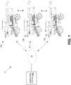
FIG. 1 , shown is a schematic diagram that illustrates an example network topology for an embodiment of an auto-farm planning system 10. In one embodiment, the auto-farm planning system 10 comprises one or more agricultural machines 12 (e.g., three (3) shown inFIG. 1 , 12A, 12B, and 12C, though other quantities may be used in some embodiments), anetwork 14, which may include plural networks, and one ormore computing systems 16. It should be appreciated within the context of the present disclosure that, though shown using agricultural machines 12 embodied as combine harvesters, some embodiments may utilize other agricultural machines (e.g., planters, sprayers, etc.) in the same or different quantities, and hence are contemplated to be within the scope of the disclosure. Further, it is noted that the combine harvesters 12 are shown inFIG. 1 without the attached header for purposes of brevity, with the understanding that one of a plurality of different types of headers may be used with each of the combine harvesters 12. The auto-farm planning system 10 is depicted inFIG. 1 withplural computing systems 16, including a remotely-locatedcomputing system 16A, and on-board computing systems - The
computing system 16A may be a server, computer (e.g., personal computer), or other type of computing device and/or software that is located at a business (e.g., farm, an Internet Service Provider (ISP) facility, regional or local agricultural machine manufacturer's representative facility, manufacturer's facility, among others), residence, or other locations remote from the field. Thecomputing system 16A may be communicatively coupled to thecomputing systems 16B-16D over thenetwork 14 in a master-slave arrangement, or in some embodiments, communicatively coupled to one of the computing systems 16 (e.g., 16B) in a master-slave arrangement, with theother computing systems 16C-16D communicatively coupled to thecomputing system 16B in a sub-master-slave arrangement. In some embodiments, communications among thecomputing systems 16A-16D may comprise a peer-to-peer manner of communication, ad-hoc, or a mix of any two or more of the aforementioned network topologies among others well-known to those having ordinary skill in the art. - The
network 14 may include a wide area network, such as the Internet, and local area networks, such as a radio frequency (RF) network, cellular network, POTS, WiFi, WiMax, satellite, among others. For instance, thecomputing system 16A may host a web-service, or serve as a gateway to one or more other servers in the Internet, and be coupled to thecomputing systems 16B-16D of theagricultural machines 12A-12C, respectively, over a wireless, cellular connection. In some embodiments, a cellular connection may be implemented between thecomputing system 16A and thecomputing system 16B of theagricultural machine 12A, and communications between thecomputing systems agricultural machines - The agricultural machines 12 are depicted as combine harvesters for illustrative purposes, and since operations of a combine harvester are known to those having ordinary skill in the art, further description of their operations are omitted here for brevity.
- In one example operation of an auto-
farm planning system 10, and referring to an implementation initially where there is a single agricultural machine involved, such asagricultural machine 12A, an operator of theagricultural machine 12A may navigate theagricultural machine 12A down a road to reach a field. Note that reference to an operator may refer to an operator that is residing in the cab of the agricultural machine and manipulating on-board navigational controls. In some embodiments, reference to an operator may refer to an operator that is navigating theagricultural machine 12A from a remote location, such as in semi-autonomous farming implementations. In some embodiments, autonomous systems may be used where there is no direct operator influence on machine navigation. Attention is directed toFIG. 2 (with continued reference toFIG. 1 ), which shows adisplay screen 18 withaerial imagery 20 displayed thereon. Note that reference herein to display screens inFIGS. 2-7 also have a continued reference toFIG. 1 . Thedisplay screen 18 may be part of, or otherwise associated with one or more of thecomputing systems 16, and in this example, is associated with thecomputing system 16B of theagricultural machine 12A. In some embodiments, thedisplay screen 18 may be disposed on a portable communications device, such as a cell-phone, tablet, laptop, etc.), or be integrated in a virtual headset. As the operator navigates theagricultural machine 12A to a field to be farmed (e.g., in the case of combine harvesters, farming generally refers to harvesting crop material as the combine harvester traverses the field, including threshing, separating, and cleaning grain while discharging from themachine 12A material other than grain (MOG) as is known), thecomputing system 16B presents the top-down,aerial imagery 20 on thedisplay screen 18 for observance by the operator (e.g., in the cab, or in some embodiments, at a remote location). In some embodiments, a local cache of maps may be installed in thecomputing system 16B, or in some embodiments, theaerial imagery 20 may be streamed to thecomputing system 16B in real-time or near real-time (e.g., continually, or on a periodic or aperiodic basis). Theaerial imagery 20 comprises plural fields, such asfields agricultural machine 12A. In some embodiments, the aerial imagery 20 (and objects within it) may comprise a snapshot of real aerial imagery, or in some embodiments, a corresponding graphic (e.g., icon or symbol or geometrical objects translated from, and representing, the same), or a mix of each (e.g., a graphic representing theagricultural machine 12A overlaid on a snapshot of the real aerial imagery). - The boundaries of the fields 24-28 are identified by the
computing system 16B (or in some embodiments, thecomputing system 16A) without operator intervention. Note that reference to processing performed by thecomputing system 16B also contemplates embodiments where such processing is may be performed by thecomputing system 16A (or other computing systems, such as those residing on other agricultural machines), and vice versa. As the operator navigates theagricultural machine 12A along the road, in close proximity (e.g., within a ten (10) mile radius, for instance) to the fields 22-28, thecomputing system 16B determines the boundaries of each of the fields, and highlights the boundaries as depicted inFIG. 2 forfield 22 with dashed lines along the perimeter of thefield 22. It should be appreciated that boundaries for the other fields 24-28 are likewise highlighted, but for facilitating an understanding of the description, the highlighted boundaries are only depicted for thefield 22 in the examples that follows. As theagricultural machine 12A travels along the road, thecomputing system 16B updates theaerial imagery 20 to reflect the movement of theagricultural machine 12A, as is known according to various web-based navigators. In some embodiments, thecomputing system 16A located remotely from thefield 22 may identify the boundaries and communicate theaerial imagery 20 and highlighted boundaries to thecomputing system 16B of theagricultural machine 12A. In either case, the identification of the boundaries is done without requiring operator input explicitly requesting or otherwise instructing thecomputing systems - Note that some embodiments enable editing of the identified boundaries. For instance, if the boundaries are to be optimized (e.g., for minor corrections, for joint fields, etc.), the
computing system 16B enables operator intervention to edit the boundaries. - Referring now to
FIG. 3 , with continued reference toFIG. 1 , at a time corresponding to entry by theagricultural machine 12A onto thefield 22, for instance, thecomputing system 16B (e.g., through cooperation with guidance systems of theagricultural machine 12A) detects the entry of theagricultural machine 12A onto thefield 22 and records the entry point. For instance, the recording of the entry point may be helpful for future visits to thefield 22 and associated path determinations. In some embodiments, thecomputing system 16A detects the entry of theagricultural machine 12A, as indicated generally above. In response to detecting the entry of theagricultural machine 12A onto the field, thecomputing system 16B selects thefield 22. The selection of the field boundary can be communicated, if the selection is not already performed by thecomputing system 16A, to theremote computing system 16A over the network 14 (or manually, via saving the selected field onto a storage media and loading to thecomputing system 16A), which enables maintenance of one or more data structures (e.g., databases) of fields farmed using the agricultural machine. Other data may be stored, such as the manufacturer of the agricultural machine, the product dispensed on the field (e.g., in the case of planting or spraying applications), environmental conditions, among other useful data. Thecomputing system 16B displays on thedisplay screen 18 theaerial imagery 20 and theagricultural machine 12A residing in the highlightedfield 22, as depicted inFIG. 3 . - In one embodiment, responsive to entry of the
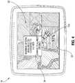
agricultural machine 12A onto thefield 22, and without operator intervention (e.g., without input aside from navigating theagricultural machine 12B onto and within the field), thecomputing system 16B (or in some embodiments, offloaded to thecomputing system 16A or a processing collaboration of bothcomputing systems agricultural machine 12A is to traverse, all or in part (e.g., the latter when sharing workload with other agricultural machines), to perform farming operations. Referring toFIG. 4 (where the highlighting is omitted hereinafter for brevity), thecomputing system 16B may reverse engineer the prior waylines used to farm thefield 22 based on the aerial imagery. For instance, thecomputing system 16B (or in some embodiments, thecomputing system 16A, which then provides the calculations to thecomputing system 16B over the network, 14) may calculate waylines using optical recognition from theaerial imagery 20. Theaerial imagery 20 may reveal furrows from prior farming operations on thefield 22, which are used in the wayline calculations. The path 30 (e.g., the waylines) are presented on thedisplay screen 18 overlaid on theaerial imagery 20. - In some embodiments, the
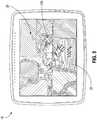
computing system 16B (or in some embodiments, thecomputing system 16A) may provide a path that is optimal. Referring toFIG. 5 , shown is the provision (and display) of apath 32 embodied as A-lines. Thecomputing system 16B may determine the A-lines from one or more parameters and their respective optimizations in covering farming operations of thefield 22, including distance to be traveled by theagricultural machine 12A based on the identified boundaries, anticipated fuel consumption to cover the distance traveled, the entry point to thefield 22, among other inputs. In some embodiments, thecomputing system 16B may receive operator inputs in the A-line determinations, such as customizations for certain features that are not revealed by the aerial imagery 20 (e.g., suitable directions on steep hills, avoidance of drainage tiles among other obstacles, etc.), and/or for customizations based in part of prior historical preferences in the manner of farming thefield 22. Note that these operator inputted optimizations may be done once (e.g., the first time the auto-farm planning system 10 is implemented for the field 22), and then recorded for subsequent use of the path 32 (and hence without subsequent operator input). The A-line determinations may be based, at least in part, on existing path directions (e.g., based on the furrows identified through optical recognition of the aerial imagery 20). - Note that the displayed
aerial imagery 20 may be a browser displayed web-page that the operator, residing in the cab of theagricultural machine 12B, may enter inputs into, or in some embodiments, a locally-generated graphical user interface (GUI, e.g., non-browser based) that populates the screen with the downloaded imagery. - In some embodiments, the determination as to which path 30 (
FIG. 4 ) or 32 (FIG. 5 ) to provide to the operator (and hence be implemented during farming) may be implemented during a start-up session with auto-farm planning system software, in which the operator can be presented with an option to choose a default path determination (e.g., waylines or A-lines) at that time. The start-up session may also enable the operator to select an option where both path determinations are provided upon entering a field (e.g., either the first time or repeatedly for subsequent entries of the field), leaving the choice to the operator in real-time. For instance, with reference toFIG. 4 , a pop-upwindow 34 may be presented to the operator at a time corresponding to (e.g., after) completion of path determinations using waylines (e.g., path 30) and A-lines (e.g., path 32). It should be appreciated that the use of a pop-upwindow 34 is for illustrative purposes, and that some embodiments may use other visual (or audio/verbal) mechanisms well-known in the art to alert the operator of different path determination options. In some embodiments, the path determinations also involve a determination of the efficiency of farming thefield 22. For instance, assuming the efficiency ofoptimal path 32 at 100% (e.g., whether calculated with or without additional operator input), an efficiency of 93% may be determined forpath 30. The efficiency values may be presented to the operator on eachrespective display screen 18 inFIG. 4 (e.g., 93%) andFIG. 5 (e.g., 100%) that an operator can toggle between, or together or comparatively (e.g., relatively) on a single display screen. For instance, inFIG. 4 , both the efficiency (e.g., 93%) of thepath 30 relative to theoptimal path 32 and a tangible benefit to the difference in efficiency may be presented to the operator, as illustrated by the pop-up that states, "Savings of $764 available by changing to A-lines." It is also noted thatFIG. 4 andFIG. 5 have efficiency values overlaid onto theaerial imagery 20, though other mechanisms and/or formats for presenting the efficiencies may be used, or in some embodiments, the efficiencies may not be presented at all. - As a brief background, growers have traditionally farmed a given field according to historical reasons (e.g., "that is the way dad always farmed the land"), and hence the grower may be reluctant to try another path (e.g., path 32). The presentation to the operator of benefits in the way of costs savings if the
optimal path 32 is selected may be a strong motivator to consider adifferent path 32 than what has traditionally been taken (e.g., path 30). Variations to these efficiency values may be implemented in some embodiments. For instance, the operator may be able to select a menu option to affect changes to the savings, such as entering (or selecting) local gas rates, or chemical costs per distance, among other options to more tailor the cost savings. In some embodiments, the savings in time may be included as part of the comparison ofpaths - Note that once the
paths agricultural machine 12A and begins farming according to the selectedpath computing system 16B may remotely (e.g., via communication to thecomputing system 16A) and/or locally cache the data corresponding to theaerial imagery 20 with thedetermined path agricultural machine 12A enters thefield 22. The caching of the path determinations enables processing time to be reduced, and may reduce the bandwidth consumption between thecomputing system agricultural machine 12A may re-use the selected path. In some embodiments, the default option of presenting a comparison of both path determinations may be a repeated event (e.g., selectable repeated event), in view of differences in fuel costs (e.g., or other variables) over the years or changes to the field. Note that the boundary determinations (e.g., pre-path determinations) may similarly be cached locally or remotely, facilitating processing and reducing resource consumption when the fields 22-28 are displayed the next time theagricultural machine 12A returns to the road for accessing one of the fields 22-28. - Also noteworthy from the above description is that, unlike conventional systems, at no point in the planning process did the operator have to define a boundary (e.g., except if edits or customizations are made in the initial planning process when first employing an embodiment of an auto-
farm planning system 10 to a field), select a field (e.g., except in the initial planning process if the default option is to be presented with a comparison ofoptimal path 32 versus historical path 30), or define or select a wayline (or A-line). It should be appreciated that, though the description above is focused on the benefits of using certain embodiments of auto-farm planning systems 10 with guidance-based agricultural equipment, benefits may be realized in manually-guided agricultural machines that are supplemented with visual systems (e.g., light-bars). - Referring now to
FIG. 6 , shown on theexample display screen 18 is theaerial imagery 20 with an optional pop-upwindow 36 overlaid on theaerial imagery 20. The pop-upwindow 36 may be presented responsive to detecting that an additional agricultural machine, such asagricultural machine 12B, passed the identified boundary of thefield 22 and entered thefield 22. Thecomputing system 16B may detect (automatically) the presence of theagricultural machine 12B, or be alerted to the presence by thecomputing system 16A, by the newly enteringagricultural machine 12B, and/or by the operator of theagricultural machine 12A in some embodiments. The pop-upwindow 36 alerts the operator ofagricultural machine 12A, "MF 7625 (Steve) has entered the field. Do you want to distribute field work between all assets? (Yes/No)." Note that other variations to the manner of alerting the operator may be used. In other words, thecomputing system 16B (or in some embodiments, 16A) seeks to determine whether there is an interest by the operator in redistributing the work along the determined path amongst pluralagricultural machines window 36 is not presented, and the default operation (which may be selected during a start-up session or once upon the event occurring for use in subsequent implementations of that or other fields) may be to proceed with thecomputing system 16B redistributing the work among its host machine (assuming the computing system performing the processing resides on theagricultural machine 12A) and the otheragricultural machine 12B (and any additional agricultural machines that pass the boundary and enter the field 22) along the determined path. Thecomputing system 16B may determine the redistribution of work (e.g., the split in work) along the determined path based on one or any combination of factors for the pluralagricultural machines field 22, their respective capacities, implement width, speed, efficiency, among other factors (some of which may be inputted by the operator). One result of the redistribution of the work may be to reduce the number of turns that eachagricultural machine FIG. 6 of two (2)agricultural machines field 22 according to the shared (determined) path. In some embodiments, the operator is alerted by other known mechanisms (visually and/or verbally) in lieu of (or in addition to) the pop-upwindow 36. - Responsive to the operator selecting "yes" (e.g., via touch screen selection, maneuvering a cursor via an input device, or buttons on a panel, voice-activation, etc.) to the query in the pop-up
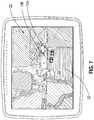
window 36 inFIG. 6 (or responsive to detecting the additionalagricultural machine 12B in some embodiments that omit the pop-up window 36), thecomputing system 16B assigns tasks along the determined path for bothagricultural machines FIG. 7 shows theaerial imagery 20 presented on thedisplay screen 18, with theagricultural machines aerial imagery 20 and moving within the imagery (and hence the field 22) along assigned routes of the path 32 (assuming, for instance, theoptimal path 32 is selected). In some embodiments, the routes along thepath 32 that eachagricultural machine determined path 32 that are yet to be traversed. Also, it is noteworthy that theagricultural machines display screen 18 of eachagricultural machine field 22, and enabling constant monitoring by the operators of therespective machines path 32. Stated otherwise, each operator is able to see the work performed by his or her respectiveagricultural machine agricultural machine - Attention is now directed to
FIG. 8A , which illustrates acontrol system 38 that may be used in an embodiment of an auto-farm planning system 10 (FIG. 1 ). It should be appreciated within the context of the present disclosure that some embodiments may include additional components or fewer or different components, and that the example depicted inFIG. 8A is merely illustrative of one embodiment among others. Further, in some embodiments, the same or similar architecture depicted inFIG. 8A may be used in each agricultural machine 12 (e.g., 12A-12C,FIG. 1 ). Thecontrol system 38 comprises thecomputing system 16. Note that thecomputing system 16, though depicted as a component of thecontrol system 38, may be a stand-alone unit, such as when implemented remotely from the field to be farmed (e.g.,computing system 16A). Thecomputing system 16 is coupled in a network 40 (e.g., a CAN network or other network, and not limited to a single network) to a guidance receiver 42 (e.g., which includes the ability to access one or more constellations jointly or separately), machine controls 44, a user interface 46 (which in one embodiment includes the display screen 18), and anetwork interface 48. In some embodiments, functionality of thenetwork interface 48 may be embedded in (or directly coupled to) thecomputing system 16, particularly for remote-server systems. The machine controls 44 collectively comprise the various actuators, sensors, and/or subsystems residing on the agricultural machine 12, including those used to control machine navigation (e.g., speed, direction (such as a steering system), etc.), implement (e.g., header or trailer) position, and/or control, internal processes, among others. Theuser interface 46 may be a keyboard, mouse, microphone, touch-type display device, joystick, steering wheel, or other devices (e.g., switches) that enable input by an operator and also enable monitoring of machine operations. As noted above, thedisplay screen 18 may be a component of theuser interface 46. Theguidance receiver 42, as is known, may enable autonomous or semi-autonomous operation of the agricultural machine 12 in cooperation with the machine controls 44 and the computing system 16 (e.g., via guidance software residing in the computing system 16). Thenetwork interface 48 comprises hardware and software that enables wireless connection among computingsystems 16 via the network 14 (FIG. 1 ) and/or over wireless RF, enabling communication via browser software to remote computing systems (e.g.,computing system 16A) through cellular links, among other telephony communication mechanisms and radio frequency communications. Thenetwork interface 48 may comprise MAC and PHY components (e.g., radio circuitry, including transceivers, antennas, etc.), as should be appreciated by one having ordinary skill in the art. As indicated above, functionality of the network interface 48 (or other components of the control system 38) may be integrated into thecomputing system 16 in some embodiments. - The
computing system 16 is configured to receive and process the information from thenetwork interface 48, theguidance receiver 42, and/or theuser interface 46. For instance, thecomputing system 16 may receive input from thedisplay screen 18, such as to enable intervention of machine operation or during planning stages by the operator (e.g., customizations for boundary identification or path determination strategies) or selection and/or input of options (e.g., through setup sessions, or real-time pop-up windows), as well as to enter various parameters. In some embodiments, thecomputing system 16 may receive input from the machine controls 44 (e.g., such as to enable feedback as to the position or status of certain devices, such as a header height and/or width, and/or speed, direction of the agricultural machine 12, etc.). Thecomputing system 16 is also configured to cause the transmission of information (and/or enable the reception of information) via thenetwork interface 48 withother computing systems 16. FIG. 8B further illustrates an example embodiment of thecomputing system 16. One having ordinary skill in the art should appreciate in the context of the present disclosure that theexample computing system 16 is merely illustrative, and that some embodiments of computing systems may comprise fewer or additional components, and/or some of the functionality associated with the various components depicted inFIG. 8B may be combined, or further distributed among additional modules, in some embodiments. It should be appreciated that, though described in the context of residing in the agricultural machine 12, in some embodiments, thecomputing system 16 or its corresponding functionality may be implemented in a computing device located outside of the field. Referring toFIG. 8B , with continued reference toFIG. 8A , thecomputing system 16 is depicted in this example as a computer system, but may be embodied as a programmable logic controller (PLC), FPGA, among other devices. It should be appreciated that certain well-known components of computer systems are omitted here to avoid obfuscating relevant features of thecomputing system 16. In one embodiment, thecomputing system 16 comprises one or more processors (also referred to herein as processor units or processing units), such asprocessor 50, input/output (I/O) interface(s) 52, andmemory 54, all coupled to one or more data busses, such as data bus 56. Thememory 54 may include any one or a combination of volatile memory elements (e.g., random-access memory RAM, such as DRAM, and SRAM, etc.) and nonvolatile memory elements (e.g., ROM, hard drive, tape, CDROM, etc.). Thememory 54 may store a native operating system, one or more native applications, emulation systems, or emulated applications for any of a variety of operating systems and/or emulated hardware platforms, emulated operating systems, etc. In some embodiments, thememory 54 may store one or more field maps (e.g., aerial imagery of one or more fields), recorded entry points, identified boundaries of the one or more fields, determined paths previously determined, customizations, and other data pertinent to auto-farming planning implementations. In the embodiment depicted inFIG. 8B , thememory 54 comprises anoperating system 58, auto-farm planning software 60, andguidance software 62. It should be appreciated that in some embodiments, additional or fewer software modules (e.g., combined functionality) may be employed in thememory 54 or additional memory. In some embodiments, a separate storage device may be coupled to the data bus 56, such as a persistent memory (e.g., optical, magnetic, and/or semiconductor memory and associated drives).- The auto-
farm planning software 60 enables automatic identification of field boundaries for one or more fields, detection of entry to a given field (e.g., past the identified boundaries) by one or more agricultural machines 12 (FIG. 1 ) and the recording of the entry points, selection of a field, the determination of a path (e.g., waylines, A-lines) for farming the selected field, the detection of other agricultural machines that enter the field, and the redistribution of work among the agricultural machines 12 operating in the selected field. The auto-farm planning software 60 also enables the provision of aerial imagery, including the overlaid objects (e.g., the overlaid pop-up windows, the overlaid agricultural machines 12, determined path, etc.) on thedisplay screen 18, as well as the communication to/from other computing systems 16 (e.g., via the I/O interfaces 52 and thenetwork interface 48 of the control system 38) of determined plans, identified boundaries, and/or workload redistribution plans, among other pertinent data. - The
guidance software 62 may coordinate inputs from theguidance receiver 42 and output control signals to one or more machine controls 44 to enable guided traversal and/or performance of various farming operations on a field based on the determined path provided by the auto-farm planning software 60. In some embodiments, the functionality (e.g., code) of the auto-farm planning software 60 may be embodied in theguidance software 62, and in some embodiments, the functionality (e.g., code) of theguidance software 62 may be embodied in the auto-farm planning software 60. - Execution of the
software modules processor 50 under the management and/or control of theoperating system 58. In some embodiments, theoperating system 58 may be omitted and a more rudimentary manner of control implemented. Theprocessor 50 may be embodied as a custom-made or commercially available processor, a central processing unit (CPU) or an auxiliary processor among several processors, a semiconductor based microprocessor (in the form of a microchip), a macroprocessor, one or more application specific integrated circuits (ASICs), a plurality of suitably configured digital logic gates, and/or other well-known electrical configurations comprising discrete elements both individually and in various combinations to coordinate the overall operation of thecomputing system 16. - The I/O interfaces 52 provide one or more interfaces to the
network 40 and other networks. In other words, the I/O interfaces 52 may comprise any number of interfaces for the input and output of signals (e.g., analog or digital data) for conveyance of information (e.g., data) over thenetwork 40. The input may comprise input by an operator (local or remote) through the user interface 46 (e.g., a keyboard, joystick, steering wheel, or mouse or other input device (or audible input in some embodiments)), and input from signals carrying information from one or more of the components of thecontrol system 38, such as theguidance receiver 42, machine controls 44, and/or thenetwork interface 48, among other devices. - When certain embodiments of the
computing system 16 are implemented at least in part as software (including firmware), as depicted inFIG. 8B , it should be noted that the software can be stored on a variety of non-transitory computer-readable medium for use by, or in connection with, a variety of computer-related systems or methods. In the context of this document, a computer-readable medium may comprise an electronic, magnetic, optical, or other physical device or apparatus that may contain or store a computer program (e.g., executable code or instructions) for use by or in connection with a computer-related system or method. The software may be embedded in a variety of computer-readable mediums for use by, or in connection with, an instruction execution system, apparatus, or device, such as a computer-based system, processor-containing system, or other system that can fetch the instructions from the instruction execution system, apparatus, or device and execute the instructions. - When certain embodiment of the
computing system 16 are implemented at least in part as hardware, such functionality may be implemented with any or a combination of the following technologies, which are all well-known in the art: a discrete logic circuit(s) having logic gates for implementing logic functions upon data signals, an application specific integrated circuit (ASIC) having appropriate combinational logic gates, a programmable gate array(s) (PGA), a field programmable gate array (FPGA), etc. - In view of the above description, it should be appreciated that one embodiment of an auto-
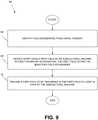
farm planning method 64, depicted inFIG. 9 , comprises identifying field boundaries from aerial imagery (66); detecting entry upon a first field by an agricultural machine without operator intervention, the first field within the identified field boundaries (68); and providing a first path to be traversed in the first field at least in part by the agricultural machine (70). - Any process descriptions or blocks in flow diagrams should be understood as representing modules, segments, or portions of code which include one or more executable instructions for implementing specific logical functions or steps in the process, and alternate implementations are included within the scope of the embodiments in which functions may be executed out of order from that shown or discussed, including substantially concurrently or in reverse order, depending on the functionality involved, as would be understood by those reasonably skilled in the art of the present disclosure.
- It should be emphasized that the above-described embodiments of the present disclosure, particularly, any "preferred" embodiments, are merely possible examples of implementations, merely set forth for a clear understanding of the principles of the disclosure.
Claims (2)
- A method, comprising:identifying (66) field boundaries from aerial imagery (20);detecting (68) entry upon a first field (22) by an agricultural machine (12) without operator intervention, the first field within the identified field boundaries; andproviding (70) a first path to be traversed in the first field at least in part by the agricultural machine (12);characterised in that the providing of the first path comprises calculating the first path that farms the entire first field based on optical recognition in the aerial imagery (20) of furrows that track the prior path of an agricultural machine during farming operations.
- An agricultural machine (12), comprising:a chassis coupled to rotating elements to cause traversal across a field (22);a wireless network interface (48); anda computing system (16) configured to:identify field boundaries from aerial imagery (20) responsive to the agricultural machine traveling in close proximity to a field located within the identified field boundaries;detect without operator intervention when the agricultural machine (12) enters the field; andprovide a path (30) to be traversed in the field at least in part by the agricultural machine, the path corresponding to a farming path for the entire field;characterised in that the computing system (16) is configured to provide the path to be traversed by calculating the first path that farms the entire first field based on optical recognition in the aerial imagery (30) of furrows that track the prior path of an agricultural machine during farming operations.
Applications Claiming Priority (2)
| Application Number | Priority Date | Filing Date | Title |
|---|---|---|---|
| US201361844476P | 2013-07-10 | 2013-07-10 | |
| PCT/US2014/046216WO2015006600A1 (en) | 2013-07-10 | 2014-07-10 | Automating distribution of work in a field |
Publications (2)
| Publication Number | Publication Date |
|---|---|
| EP3018987A1 EP3018987A1 (en) | 2016-05-18 |
| EP3018987B1true EP3018987B1 (en) | 2020-09-02 |
Family
ID=51263517
Family Applications (1)
| Application Number | Title | Priority Date | Filing Date |
|---|---|---|---|
| EP14747216.1AActiveEP3018987B1 (en) | 2013-07-10 | 2014-07-10 | Automating distribution of work in a field |
Country Status (3)
| Country | Link |
|---|---|
| US (1) | US10180328B2 (en) |
| EP (1) | EP3018987B1 (en) |
| WO (1) | WO2015006600A1 (en) |
Cited By (1)
| Publication number | Priority date | Publication date | Assignee | Title |
|---|---|---|---|---|
| EP3955078B1 (en)* | 2019-04-09 | 2025-01-01 | FJ Dynamics Technology Co., Ltd | Travel path planning system for multiple automatic harvesters and method therefor |
Families Citing this family (93)
| Publication number | Priority date | Publication date | Assignee | Title |
|---|---|---|---|---|
| BR112015008318A2 (en) | 2013-09-23 | 2017-07-04 | Farmobile Llc | relay device, and server and agriculture data exchange systems |
| WO2015057638A1 (en)* | 2013-10-14 | 2015-04-23 | Kinze Manufacturing, Inc. | Autonomous systems, methods, and apparatus for ag based operations |
| US9303998B2 (en)* | 2013-11-18 | 2016-04-05 | Agco Corporation | System and method for automatically generating vehicle guidance waypoints and waylines |
| US11039583B2 (en) | 2015-04-10 | 2021-06-22 | Husqvarna Ab | Watering system with adaptive components |
| GB2549986B (en)* | 2016-05-06 | 2020-07-15 | Jaguar Land Rover Ltd | Systems and methods for controlling vehicle manoeuvers |
| US10048693B2 (en)* | 2016-06-10 | 2018-08-14 | Trimble Inc. | Transparently achieving auto-guidance of a mobile machine |
| US10795351B2 (en)* | 2016-07-19 | 2020-10-06 | Raven Industries, Inc. | System and method for autonomous control of agricultural machinery and equipment |
| US9942440B2 (en) | 2016-07-25 | 2018-04-10 | Clearag, Inc. | Image-based field boundary detection and identification |
| CA3038694A1 (en)* | 2016-09-29 | 2018-04-05 | Agro Intelligence Aps | A system and a method for optimizing the trajectory to be followed when weeding crops |
| EP3518647B1 (en)* | 2016-09-29 | 2020-12-23 | Agro Intelligence ApS | A system and a method for determining a trajectory to be followed by an agricultural work vehicle |
| JP6773523B2 (en)* | 2016-11-09 | 2020-10-21 | ヤンマーパワーテクノロジー株式会社 | Field registration system |
| DE112017006128T5 (en)* | 2016-12-01 | 2019-08-14 | Kinze Manufacturing, Inc. | A system, method and / or apparatus for providing a display unit and an interface for use with an agricultural implement |
| JP6701064B2 (en)* | 2016-12-14 | 2020-05-27 | 株式会社クボタ | Travel route generator |
| JP7034589B2 (en) | 2016-12-28 | 2022-03-14 | ヤンマーパワーテクノロジー株式会社 | Work vehicle route generation system |
| JP6735685B2 (en)* | 2017-01-20 | 2020-08-05 | 株式会社クボタ | Travel control device |
| DE102017115150A1 (en)* | 2017-07-06 | 2019-01-10 | Horsch Maschinen Gmbh | System and method for local and / or remote monitoring and / or control of vehicles |
| US20190353483A1 (en)* | 2018-05-15 | 2019-11-21 | Deere & Company | Coverage-based system and method of planning a turn path for a vehicle |
| US11653588B2 (en) | 2018-10-26 | 2023-05-23 | Deere & Company | Yield map generation and control system |
| US11467605B2 (en) | 2019-04-10 | 2022-10-11 | Deere & Company | Zonal machine control |
| US11079725B2 (en) | 2019-04-10 | 2021-08-03 | Deere & Company | Machine control using real-time model |
| US11641800B2 (en) | 2020-02-06 | 2023-05-09 | Deere & Company | Agricultural harvesting machine with pre-emergence weed detection and mitigation system |
| US11589509B2 (en) | 2018-10-26 | 2023-02-28 | Deere & Company | Predictive machine characteristic map generation and control system |
| US11672203B2 (en) | 2018-10-26 | 2023-06-13 | Deere & Company | Predictive map generation and control |
| US11178818B2 (en) | 2018-10-26 | 2021-11-23 | Deere & Company | Harvesting machine control system with fill level processing based on yield data |
| US11957072B2 (en) | 2020-02-06 | 2024-04-16 | Deere & Company | Pre-emergence weed detection and mitigation system |
| US12069978B2 (en) | 2018-10-26 | 2024-08-27 | Deere & Company | Predictive environmental characteristic map generation and control system |
| US11240961B2 (en) | 2018-10-26 | 2022-02-08 | Deere & Company | Controlling a harvesting machine based on a geo-spatial representation indicating where the harvesting machine is likely to reach capacity |
| CA3120202C (en)* | 2018-11-15 | 2023-10-03 | Raven Industries, Inc. | Integrated platform and common software structural architecture for autonomous agricultural vehicle and machinery operation. |
| CN110209153A (en)* | 2019-04-09 | 2019-09-06 | 丰疆智能科技股份有限公司 | The lodging traveling planning system and its method of automatic harvester |
| US11856882B2 (en)* | 2019-04-10 | 2024-01-02 | Kansas Stte University Research Foundation | Autonomous robot system for steep terrain farming operations |
| US11234366B2 (en) | 2019-04-10 | 2022-02-01 | Deere & Company | Image selection for machine control |
| US11778945B2 (en) | 2019-04-10 | 2023-10-10 | Deere & Company | Machine control using real-time model |
| JP2020197792A (en)* | 2019-05-31 | 2020-12-10 | ヤンマーパワーテクノロジー株式会社 | Autonomous driving system |
| EP4068035B1 (en)* | 2019-11-25 | 2025-02-12 | Murata Machinery, Ltd. | Autonomous traveling vehicle, control method, and program |
| US11748824B2 (en)* | 2020-01-31 | 2023-09-05 | Deere & Company | Systems and methods for site traversability sensing |
| US12035648B2 (en) | 2020-02-06 | 2024-07-16 | Deere & Company | Predictive weed map generation and control system |
| US12329148B2 (en) | 2020-02-06 | 2025-06-17 | Deere & Company | Predictive weed map and material application machine control |
| US12225846B2 (en) | 2020-02-06 | 2025-02-18 | Deere & Company | Machine control using a predictive map |
| US12016257B2 (en) | 2020-02-19 | 2024-06-25 | Sabanto, Inc. | Methods for detecting and clearing debris from planter gauge wheels, closing wheels and seed tubes |
| US11961027B2 (en)* | 2020-03-06 | 2024-04-16 | Caterpillar Inc. | Methods and systems for effective utilization of autonomous machines |
| US11282401B2 (en) | 2020-03-23 | 2022-03-22 | Blue White Robotics Ltd | Multi-dimension operation of autonomous vehicles |
| US11477940B2 (en) | 2020-03-26 | 2022-10-25 | Deere & Company | Mobile work machine control based on zone parameter modification |
| US11669093B2 (en)* | 2020-03-26 | 2023-06-06 | Deere & Company | Mobile work machine control based on control zone map data |
| JP7104106B2 (en)* | 2020-07-16 | 2022-07-20 | ヤンマーパワーテクノロジー株式会社 | Work vehicle route generation system |
| US12069986B2 (en) | 2020-10-09 | 2024-08-27 | Deere & Company | Map generation and control system |
| US12386354B2 (en) | 2020-10-09 | 2025-08-12 | Deere & Company | Predictive power map generation and control system |
| US11849672B2 (en) | 2020-10-09 | 2023-12-26 | Deere & Company | Machine control using a predictive map |
| US12419220B2 (en) | 2020-10-09 | 2025-09-23 | Deere & Company | Predictive map generation and control system |
| US11864483B2 (en) | 2020-10-09 | 2024-01-09 | Deere & Company | Predictive map generation and control system |
| US12422847B2 (en) | 2020-10-09 | 2025-09-23 | Deere & Company | Predictive agricultural model and map generation |
| US11592822B2 (en) | 2020-10-09 | 2023-02-28 | Deere & Company | Machine control using a predictive map |
| US11874669B2 (en) | 2020-10-09 | 2024-01-16 | Deere & Company | Map generation and control system |
| US11675354B2 (en) | 2020-10-09 | 2023-06-13 | Deere & Company | Machine control using a predictive map |
| US11927459B2 (en) | 2020-10-09 | 2024-03-12 | Deere & Company | Machine control using a predictive map |
| US11650587B2 (en) | 2020-10-09 | 2023-05-16 | Deere & Company | Predictive power map generation and control system |
| US11711995B2 (en) | 2020-10-09 | 2023-08-01 | Deere & Company | Machine control using a predictive map |
| US11474523B2 (en) | 2020-10-09 | 2022-10-18 | Deere & Company | Machine control using a predictive speed map |
| US11845449B2 (en) | 2020-10-09 | 2023-12-19 | Deere & Company | Map generation and control system |
| US11727680B2 (en) | 2020-10-09 | 2023-08-15 | Deere & Company | Predictive map generation based on seeding characteristics and control |
| US11825768B2 (en) | 2020-10-09 | 2023-11-28 | Deere & Company | Machine control using a predictive map |
| US11844311B2 (en) | 2020-10-09 | 2023-12-19 | Deere & Company | Machine control using a predictive map |
| US11946747B2 (en) | 2020-10-09 | 2024-04-02 | Deere & Company | Crop constituent map generation and control system |
| US12013245B2 (en) | 2020-10-09 | 2024-06-18 | Deere & Company | Predictive map generation and control system |
| US11635765B2 (en) | 2020-10-09 | 2023-04-25 | Deere & Company | Crop state map generation and control system |
| US11895948B2 (en) | 2020-10-09 | 2024-02-13 | Deere & Company | Predictive map generation and control based on soil properties |
| US11983009B2 (en) | 2020-10-09 | 2024-05-14 | Deere & Company | Map generation and control system |
| US11889788B2 (en) | 2020-10-09 | 2024-02-06 | Deere & Company | Predictive biomass map generation and control |
| US12178158B2 (en) | 2020-10-09 | 2024-12-31 | Deere & Company | Predictive map generation and control system for an agricultural work machine |
| US11871697B2 (en) | 2020-10-09 | 2024-01-16 | Deere & Company | Crop moisture map generation and control system |
| US11849671B2 (en) | 2020-10-09 | 2023-12-26 | Deere & Company | Crop state map generation and control system |
| US11889787B2 (en) | 2020-10-09 | 2024-02-06 | Deere & Company | Predictive speed map generation and control system |
| US12250905B2 (en) | 2020-10-09 | 2025-03-18 | Deere & Company | Machine control using a predictive map |
| WO2022098785A1 (en) | 2020-11-04 | 2022-05-12 | Blue River Technology Inc. | Farming vehicle field boundary identification |
| US20220207622A1 (en)* | 2020-12-29 | 2022-06-30 | Agco Corporation | Forage loss monitoring |
| US12127500B2 (en) | 2021-01-27 | 2024-10-29 | Deere & Company | Machine control using a map with regime zones |
| US12296694B2 (en) | 2021-03-10 | 2025-05-13 | Techtronic Cordless Gp | Lawnmowers |
| US12265921B2 (en) | 2021-06-08 | 2025-04-01 | Deere & Company | Milestone prediction of fuel and chemical usage |
| US11778935B2 (en) | 2021-09-13 | 2023-10-10 | Deere & Company | Controlling operating envelope for off-road equipment based on a digital fence |
| US12229886B2 (en) | 2021-10-01 | 2025-02-18 | Deere & Company | Historical crop state model, predictive crop state map generation and control system |
| US12085955B2 (en) | 2021-10-19 | 2024-09-10 | Deere & Company | Methods, apparatus, and articles of manufacture to select track paths for one or more vehicles in a field |
| US12310286B2 (en) | 2021-12-14 | 2025-05-27 | Deere & Company | Crop constituent sensing |
| US12302791B2 (en) | 2021-12-20 | 2025-05-20 | Deere & Company | Crop constituents, predictive mapping, and agricultural harvester control |
| US12245549B2 (en) | 2022-01-11 | 2025-03-11 | Deere & Company | Predictive response map generation and control system |
| US12082531B2 (en) | 2022-01-26 | 2024-09-10 | Deere & Company | Systems and methods for predicting material dynamics |
| JP2023119866A (en)* | 2022-02-17 | 2023-08-29 | ヤンマーホールディングス株式会社 | Area setting method, work vehicle, and automated travelling system |
| US12295288B2 (en) | 2022-04-05 | 2025-05-13 | Deere &Company | Predictive machine setting map generation and control system |
| US12298767B2 (en) | 2022-04-08 | 2025-05-13 | Deere & Company | Predictive material consumption map and control |
| US12358493B2 (en) | 2022-04-08 | 2025-07-15 | Deere & Company | Systems and methods for predictive power requirements and control |
| US12284934B2 (en) | 2022-04-08 | 2025-04-29 | Deere & Company | Systems and methods for predictive tractive characteristics and control |
| US12058951B2 (en) | 2022-04-08 | 2024-08-13 | Deere & Company | Predictive nutrient map and control |
| EP4310621B1 (en) | 2022-07-19 | 2025-02-12 | Techtronic Cordless GP | Display for controlling robotic tool |
| EP4340296B1 (en) | 2022-07-29 | 2025-04-09 | Techtronic Cordless GP | Generation of a cryptography key for a robotic garden tool |
| US12427862B2 (en)* | 2022-09-05 | 2025-09-30 | Kawasaki Motors, Ltd. | Spread assist device |
Family Cites Families (106)
| Publication number | Priority date | Publication date | Assignee | Title |
|---|---|---|---|---|
| DE4423083A1 (en)* | 1993-07-13 | 1995-01-19 | Deutsche Aerospace | Process for working a surface area on the ground, and arrangement for carrying out the process |
| IL113913A (en)* | 1995-05-30 | 2000-02-29 | Friendly Machines Ltd | Navigation method and system |
| DE19629618A1 (en)* | 1996-07-23 | 1998-01-29 | Claas Ohg | Route planning system for agricultural work vehicles |
| DE19705842A1 (en) | 1997-02-15 | 1998-08-20 | Same Deutz Fahr Spa | Field crop harvesting method |
| EP0975209B1 (en)* | 1997-04-16 | 2003-05-21 | Carnegie Mellon University | Agricultural harvester with robotic control |
| US5987383C1 (en)* | 1997-04-28 | 2006-06-13 | Trimble Navigation Ltd | Form line following guidance system |
| US6199000B1 (en)* | 1998-07-15 | 2001-03-06 | Trimble Navigation Limited | Methods and apparatus for precision agriculture operations utilizing real time kinematic global positioning system systems |
| AUPP679598A0 (en)* | 1998-10-27 | 1998-11-19 | Agsystems Pty Ltd | A vehicle navigation apparatus |
| US6119069A (en)* | 1999-03-01 | 2000-09-12 | Case Corporation | System and method for deriving field boundaries using alpha shapes |
| US6205381B1 (en)* | 1999-03-26 | 2001-03-20 | Caterpillar Inc. | Method and apparatus for providing autoguidance for multiple agricultural machines |
| US6236916B1 (en)* | 1999-03-29 | 2001-05-22 | Caterpillar Inc. | Autoguidance system and method for an agricultural machine |
| US6236924B1 (en)* | 1999-06-21 | 2001-05-22 | Caterpillar Inc. | System and method for planning the operations of an agricultural machine in a field |
| US6424295B1 (en)* | 2000-02-22 | 2002-07-23 | Trimble Navigation Limited | GPS weather data recording system for use with the applications of chemicals to agricultural fields |
| WO2001095162A1 (en)* | 2000-06-05 | 2001-12-13 | Ag-Chem Equipment Company, Inc. | System and method for creating demo application maps for site-specific farming |
| CA2425985C (en)* | 2000-10-13 | 2013-01-08 | Paxgrid Telemetric Systems Inc. | Automotive telemetry protocol |
| US6549849B2 (en)* | 2001-06-25 | 2003-04-15 | Trimble Navigation Ltd. | Guidance pattern allowing for access paths |
| US6549852B2 (en)* | 2001-07-13 | 2003-04-15 | Mzb Technologies, Llc | Methods and systems for managing farmland |
| US6728607B1 (en)* | 2002-10-03 | 2004-04-27 | Deere & Company | Method and system for determining an energy-efficient path of a machine |
| US7689354B2 (en)* | 2003-03-20 | 2010-03-30 | Hemisphere Gps Llc | Adaptive guidance system and method |
| US7010425B2 (en)* | 2003-03-31 | 2006-03-07 | Deere & Company | Path planner and a method for planning a path of a work vehicle |
| US7228214B2 (en)* | 2003-03-31 | 2007-06-05 | Deere & Company | Path planner and method for planning a path plan having a spiral component |
| US6907336B2 (en)* | 2003-03-31 | 2005-06-14 | Deere & Company | Method and system for efficiently traversing an area with a work vehicle |
| US6934615B2 (en)* | 2003-03-31 | 2005-08-23 | Deere & Company | Method and system for determining an efficient vehicle path |
| US7110881B2 (en)* | 2003-10-07 | 2006-09-19 | Deere & Company | Modular path planner |
| DE102004027242A1 (en)* | 2004-06-03 | 2005-12-22 | Claas Selbstfahrende Erntemaschinen Gmbh | Route planning system for agricultural machines |
| US7398137B2 (en)* | 2004-08-25 | 2008-07-08 | Caterpillar Inc. | System and method for remotely controlling machine operations using mapping information |
| US7245999B2 (en)* | 2005-01-31 | 2007-07-17 | Trimble Navigation Limited | Construction machine having location based auto-start |
| US7451030B2 (en)* | 2005-02-04 | 2008-11-11 | Novariant, Inc. | System and method for interactive selection and determination of agricultural vehicle guide paths offset from each other with varying curvature along their length |
| US7256388B2 (en)* | 2005-02-04 | 2007-08-14 | Novariant, Inc. | System and method for interactive selection of agricultural vehicle guide paths through a graphical user interface other than moving the vehicle |
| DE102005008105A1 (en)* | 2005-02-21 | 2006-08-31 | Amazonen-Werke H. Dreyer Gmbh & Co. Kg | Electronic Machine Management System |
| US7490678B2 (en)* | 2005-04-21 | 2009-02-17 | A.I.L., Inc. | GPS controlled guidance system for farm tractor/implement combination |
| US7860628B2 (en)* | 2005-06-09 | 2010-12-28 | Trimble Navigation Limited | System for guiding a farm implement between swaths |
| US8185275B2 (en)* | 2005-07-01 | 2012-05-22 | Deere & Company | System for vehicular guidance with respect to harvested crop |
| EP3067771B1 (en)* | 2006-03-17 | 2017-11-08 | iRobot Corporation | Robot confinement |
| DE102006015203A1 (en)* | 2006-03-30 | 2007-11-15 | Claas Selbstfahrende Erntemaschinen Gmbh | Method for controlling agricultural machine systems |
| DE102006019216A1 (en)* | 2006-04-21 | 2007-10-25 | Claas Selbstfahrende Erntemaschinen Gmbh | Method for controlling an agricultural machine system |
| US7848262B2 (en)* | 2006-06-26 | 2010-12-07 | The Boeing Company | Neural network-based mobility management for healing mobile ad hoc radio networks |
| US7591226B2 (en)* | 2006-11-03 | 2009-09-22 | Cnh America Llc | Automatic path generation for tramlines |
| US7934095B2 (en)* | 2006-11-10 | 2011-04-26 | Toyota Motor Engineering & Manufacturing North America, Inc. | Method for exchanging messages and verifying the authenticity of the messages in an ad hoc network |
| US7813843B2 (en)* | 2007-01-04 | 2010-10-12 | Cisco Technology, Inc | Ad-hoc mobile IP network for intelligent transportation system |
| US7706948B2 (en)* | 2007-03-02 | 2010-04-27 | Cnh America Llc | Method for creating spiral swaths for irregular field boundaries |
| US7747370B2 (en)* | 2007-04-03 | 2010-06-29 | Cnh America Llc | Method for creating end of row turns for agricultural vehicles |
| US8209075B2 (en)* | 2007-07-31 | 2012-06-26 | Deere & Company | Method and system for generating end turns |
| US8635011B2 (en)* | 2007-07-31 | 2014-01-21 | Deere & Company | System and method for controlling a vehicle in response to a particular boundary |
| US8924030B2 (en)* | 2008-01-24 | 2014-12-30 | Cnh Industrial America Llc | Method and apparatus for optimization of agricultural field operations using weather, product and environmental information |
| US8160765B2 (en) | 2008-03-03 | 2012-04-17 | Cnh America Llc | Method and system for coordinated vehicle control with wireless communication |
| US20090234859A1 (en)* | 2008-03-17 | 2009-09-17 | International Business Machines Corporation | Swarm creation in a vehicle-to-vehicle network |
| US8175775B2 (en)* | 2008-06-11 | 2012-05-08 | Cnh America Llc | System and method employing short range communications for establishing performance parameters of an exemplar agricultural machine among a plurality of like-purpose agricultural machines |
| US8515626B2 (en)* | 2008-07-22 | 2013-08-20 | Trimble Navigation Limited | System and method for machine guidance control |
| US9152938B2 (en)* | 2008-08-11 | 2015-10-06 | Farmlink Llc | Agricultural machine and operator performance information systems and related methods |
| US8280595B2 (en)* | 2008-08-12 | 2012-10-02 | Cnh America Llc | System and method employing short range communications for communicating and exchanging operational and logistical status information among a plurality of agricultural machines |
| US8195358B2 (en)* | 2008-09-11 | 2012-06-05 | Deere & Company | Multi-vehicle high integrity perception |
| US8639408B2 (en)* | 2008-10-15 | 2014-01-28 | Deere & Company | High integrity coordination system for multiple off-road vehicles |
| US8862630B2 (en)* | 2009-06-03 | 2014-10-14 | Pioneer Hi-Bred International Inc | Method and system for the use of geospatial data in the development, production, and sale of agricultural seed |
| US8738238B2 (en)* | 2009-11-12 | 2014-05-27 | Deere & Company | Coordination of vehicle movement in a field |
| US8224516B2 (en)* | 2009-12-17 | 2012-07-17 | Deere & Company | System and method for area coverage using sector decomposition |
| US20110153338A1 (en)* | 2009-12-17 | 2011-06-23 | Noel Wayne Anderson | System and method for deploying portable landmarks |
| US20110160994A1 (en)* | 2009-12-29 | 2011-06-30 | Agco Corporation | Auto-detection of a field in fleet management |
| US20110160961A1 (en)* | 2009-12-29 | 2011-06-30 | Agco Corporation | Guidance using a worked edge for wayline generation |
| US8666550B2 (en)* | 2010-01-05 | 2014-03-04 | Deere & Company | Autonomous cutting element for sculpting grass |
| MX2012003002A (en) | 2010-01-15 | 2012-04-19 | Leica Geosystems Ag | A system and method of data sharing. |
| EP2353353A1 (en)* | 2010-02-05 | 2011-08-10 | Flander's Mechatronics Technology Centre v.z.w. | In use adaptation of schedule for multi-vehicle ground processing operations |
| WO2011115534A1 (en)* | 2010-03-17 | 2011-09-22 | Husqvarna Ab | Method and system for navigating a robotic garden tool |
| FR2960118B1 (en)* | 2010-05-12 | 2013-01-04 | Eads Defence & Security Sys | MANAGING CONNECTIONS OF RELAY NODES TO FORM AN AD HOC NETWORK. |
| US8744626B2 (en)* | 2010-05-27 | 2014-06-03 | Deere & Company | Managing autonomous machines across multiple areas |
| EP2590495B1 (en)* | 2010-07-07 | 2020-04-15 | Husqvarna AB | Communication and safety device for boundary aided systems |
| BE1019422A3 (en)* | 2010-07-14 | 2012-07-03 | Cnh Belgium Nv | METHOD AND APPARATUS FOR PREDICTIVE CONTROL OF AN AGRICULTURAL VEHICLE SYSTEM. |
| US9213905B2 (en)* | 2010-10-25 | 2015-12-15 | Trimble Navigation Limited | Automatic obstacle location mapping |
| US20120101679A1 (en)* | 2010-10-26 | 2012-04-26 | Noel Wayne Anderson | Method and system for enhancing operating performance of an autonomic mobile robotic device |
| CA2822893C (en)* | 2010-12-29 | 2019-03-05 | Dow Agrosciences Llc | Spray drift systems and methods including an input device |
| US8694382B2 (en)* | 2011-02-18 | 2014-04-08 | Cnh America Llc | System and method for automatic guidance control of a vehicle |
| AU2012243484B2 (en)* | 2011-04-11 | 2014-10-30 | Crown Equipment Corporation | Method and apparatus for efficient scheduling for multiple automated non-holonomic vehicles using a coordinated path planner |
| KR101334961B1 (en)* | 2011-08-03 | 2013-11-29 | 엘지전자 주식회사 | Lawn mower robot system and control method for the same |
| US9471063B2 (en)* | 2011-08-11 | 2016-10-18 | Chien Ouyang | Robotic lawn mower with network sensors |
| US8655538B2 (en)* | 2011-12-16 | 2014-02-18 | Agco Corporation | Systems and methods for switching display modes in agricultural vehicles |
| US20130174040A1 (en)* | 2011-12-30 | 2013-07-04 | Jerome Dale Johnson | Methods, apparatus and systems for generating, updating and executing a crop-planting plan |
| US20130173321A1 (en)* | 2011-12-30 | 2013-07-04 | Jerome Dale Johnson | Methods, apparatus and systems for generating, updating and executing a crop-harvesting plan |
| US20160026940A1 (en)* | 2011-12-30 | 2016-01-28 | Aglytix, Inc. | Methods, apparatus and systems for generating, updating and executing a crop-harvesting plan |
| EP2885683A4 (en)* | 2012-08-14 | 2016-06-01 | Husqvarna Ab | Boundary definition system for a robotic vehicle |
| WO2014058358A1 (en)* | 2012-10-09 | 2014-04-17 | Husqvarna Ab | Method and system for enhancing a coverage distribution of a robotic garden tool |
| JP6240384B2 (en)* | 2012-11-29 | 2017-11-29 | ヤンマー株式会社 | Autonomous traveling work system |
| GB201223363D0 (en)* | 2012-12-24 | 2013-02-06 | Agco Int Gmbh | Path planning method for agricultural vehicle guidance |
| WO2014105930A1 (en) | 2012-12-28 | 2014-07-03 | Agco Corporation | Assigning planned cooperatively cover area paths to multiple machines |
| WO2014101840A1 (en)* | 2012-12-28 | 2014-07-03 | 苏州宝时得电动工具有限公司 | Auto mowing system |
| US20140278696A1 (en)* | 2013-03-15 | 2014-09-18 | Deere & Company | Methods and apparatus to determine work paths for machines |
| US9382003B2 (en)* | 2013-03-24 | 2016-07-05 | Bee Robotics Corporation | Aerial farm robot system for crop dusting, planting, fertilizing and other field jobs |
| EP3018988A1 (en)* | 2013-07-10 | 2016-05-18 | Agco Corporation | Automation of networking a group of machines |
| DE102013107492A1 (en)* | 2013-07-15 | 2015-01-15 | Koubachi AG | System for monitoring and controlling activities of at least one gardening tool within at least one activity area |
| US9315919B2 (en) | 2013-07-30 | 2016-04-19 | Canon Kabushiki Kaisha | Scintillator plate and radiation detector |
| EP3032940B1 (en)* | 2013-08-16 | 2018-05-30 | Husqvarna AB | Intelligent grounds management system integrating robotic rover |
| US9886036B2 (en)* | 2014-02-10 | 2018-02-06 | John Bean Technologies Corporation | Routing of automated guided vehicles |
| BR102015013228B1 (en)* | 2014-06-13 | 2020-11-24 | Cnh Industrial America Llc | CONTROL SYSTEM AND METHOD FOR AN AGRICULTURAL VEHICLE |
| US10402835B2 (en)* | 2014-07-16 | 2019-09-03 | Raytheon Company | Agricultural situational awareness tool |
| EP2980669B1 (en)* | 2014-08-01 | 2017-09-20 | AGCO Corporation | Determining field characterisitics using optical recognition |
| US10109024B2 (en)* | 2014-09-05 | 2018-10-23 | The Climate Corporation | Collecting data to generate an agricultural prescription |
| US9934538B2 (en)* | 2014-09-24 | 2018-04-03 | Deere & Company | Recalling crop-specific performance targets for controlling a mobile machine |
| US9851718B2 (en)* | 2014-09-26 | 2017-12-26 | Steven R. Booher | Intelligent control apparatus, system, and method of use |
| US9788481B2 (en)* | 2014-10-28 | 2017-10-17 | Deere & Company | Robotic mower navigation system |
| US20160125331A1 (en)* | 2014-10-30 | 2016-05-05 | AgriSight, Inc. | Automated agricultural activity determination system and method |
| GB201419883D0 (en)* | 2014-11-07 | 2014-12-24 | F Robotics Acquisitions Ltd | Domestic robotic system and method |
| US9538702B2 (en)* | 2014-12-22 | 2017-01-10 | Irobot Corporation | Robotic mowing of separated lawn areas |
| US20160189445A1 (en)* | 2014-12-30 | 2016-06-30 | Agco Corporation | System for management of data files for agricultural machines |
| US9792557B2 (en)* | 2015-01-14 | 2017-10-17 | Accenture Global Services Limited | Precision agriculture system |
| US20160232621A1 (en)* | 2015-02-06 | 2016-08-11 | The Climate Corporation | Methods and systems for recommending agricultural activities |
| US9904290B2 (en)* | 2015-04-19 | 2018-02-27 | Deere & Company | Geometry-based monitoring and control of coupled mobile machines |
| EP3203341A1 (en)* | 2016-02-08 | 2017-08-09 | AGCO Corporation | Curved wayline extensions for contour path planning |
- 2014
- 2014-07-10EPEP14747216.1Apatent/EP3018987B1/enactiveActive
- 2014-07-10WOPCT/US2014/046216patent/WO2015006600A1/enactiveApplication Filing
- 2014-07-10USUS14/904,203patent/US10180328B2/enactiveActive
Non-Patent Citations (1)
| Title |
|---|
| None* |
Cited By (1)
| Publication number | Priority date | Publication date | Assignee | Title |
|---|---|---|---|---|
| EP3955078B1 (en)* | 2019-04-09 | 2025-01-01 | FJ Dynamics Technology Co., Ltd | Travel path planning system for multiple automatic harvesters and method therefor |
Also Published As
| Publication number | Publication date |
|---|---|
| WO2015006600A1 (en) | 2015-01-15 |
| EP3018987A1 (en) | 2016-05-18 |
| US20160146611A1 (en) | 2016-05-26 |
| US10180328B2 (en) | 2019-01-15 |
Similar Documents
| Publication | Publication Date | Title |
|---|---|---|
| EP3018987B1 (en) | Automating distribution of work in a field | |
| EP2980669B1 (en) | Determining field characterisitics using optical recognition | |
| US11589399B2 (en) | Automation of networking a group of machines | |
| US11696524B2 (en) | Robotic vehicle with adjustable operating area | |
| CN109154513B (en) | System and method for scout vehicle mapping | |
| US10095235B2 (en) | UAV-based sensing for worksite operations | |
| US20210026362A1 (en) | Apparatus, Systems And Methods For Automated Navigation Of Agricultural Equipment | |
| RU2701892C2 (en) | Field development planning system, field development planning method and agricultural working machine with such planning system | |
| JP5667731B1 (en) | Field guidance system, field guidance method, software, and storage medium storing software | |
| US20210064050A1 (en) | Methods and apparatus to record and execute mission plan | |
| AU2022289723B2 (en) | Guidance system to navigate intervening obstacles and methods for same | |
| JP6318805B2 (en) | Field shape determination device | |
| US20170223888A1 (en) | Curved wayline extensions for contour path planning | |
| JP6832881B2 (en) | Field management system | |
| JP2015167562A (en) | Farm field guidance system and farm field guidance method, and software and storage medium storing software | |
| WO2016100088A1 (en) | Method of path planning for autoguidance | |
| EP4018798A1 (en) | Methods and apparatus to generate a path plan | |
| EP4483250B1 (en) | Optimal path planning for an agricultural vehicle | |
| JP2021023263A (en) | Work field identification device | |
| US11266058B2 (en) | Automated check strips | |
| US12317776B2 (en) | Harvesting machine haulage vehicle coordination control | |
| JP7485586B2 (en) | Work area setting system, work area setting method, and work area setting program | |
| WO2024250216A1 (en) | Mapping correction method and apparatus, and storage medium |
Legal Events
| Date | Code | Title | Description |
|---|---|---|---|
| PUAI | Public reference made under article 153(3) epc to a published international application that has entered the european phase | Free format text:ORIGINAL CODE: 0009012 | |
| 17P | Request for examination filed | Effective date:20160210 | |
| AK | Designated contracting states | Kind code of ref document:A1 Designated state(s):AL AT BE BG CH CY CZ DE DK EE ES FI FR GB GR HR HU IE IS IT LI LT LU LV MC MK MT NL NO PL PT RO RS SE SI SK SM TR | |
| AX | Request for extension of the european patent | Extension state:BA ME | |
| DAX | Request for extension of the european patent (deleted) | ||
| STAA | Information on the status of an ep patent application or granted ep patent | Free format text:STATUS: EXAMINATION IS IN PROGRESS | |
| 17Q | First examination report despatched | Effective date:20190416 | |
| GRAP | Despatch of communication of intention to grant a patent | Free format text:ORIGINAL CODE: EPIDOSNIGR1 | |
| STAA | Information on the status of an ep patent application or granted ep patent | Free format text:STATUS: GRANT OF PATENT IS INTENDED | |
| INTG | Intention to grant announced | Effective date:20200416 | |
| GRAS | Grant fee paid | Free format text:ORIGINAL CODE: EPIDOSNIGR3 | |
| GRAA | (expected) grant | Free format text:ORIGINAL CODE: 0009210 | |
| STAA | Information on the status of an ep patent application or granted ep patent | Free format text:STATUS: THE PATENT HAS BEEN GRANTED | |
| AK | Designated contracting states | Kind code of ref document:B1 Designated state(s):AL AT BE BG CH CY CZ DE DK EE ES FI FR GB GR HR HU IE IS IT LI LT LU LV MC MK MT NL NO PL PT RO RS SE SI SK SM TR | |
| REG | Reference to a national code | Ref country code:GB Ref legal event code:FG4D | |
| REG | Reference to a national code | Ref country code:AT Ref legal event code:REF Ref document number:1307708 Country of ref document:AT Kind code of ref document:T Effective date:20200915 Ref country code:CH Ref legal event code:EP | |
| REG | Reference to a national code | Ref country code:DE Ref legal event code:R096 Ref document number:602014069684 Country of ref document:DE | |
| REG | Reference to a national code | Ref country code:IE Ref legal event code:FG4D | |
| REG | Reference to a national code | Ref country code:LT Ref legal event code:MG4D | |
| PG25 | Lapsed in a contracting state [announced via postgrant information from national office to epo] | Ref country code:HR Free format text:LAPSE BECAUSE OF FAILURE TO SUBMIT A TRANSLATION OF THE DESCRIPTION OR TO PAY THE FEE WITHIN THE PRESCRIBED TIME-LIMIT Effective date:20200902 Ref country code:SE Free format text:LAPSE BECAUSE OF FAILURE TO SUBMIT A TRANSLATION OF THE DESCRIPTION OR TO PAY THE FEE WITHIN THE PRESCRIBED TIME-LIMIT Effective date:20200902 Ref country code:NO Free format text:LAPSE BECAUSE OF FAILURE TO SUBMIT A TRANSLATION OF THE DESCRIPTION OR TO PAY THE FEE WITHIN THE PRESCRIBED TIME-LIMIT Effective date:20201202 Ref country code:GR Free format text:LAPSE BECAUSE OF FAILURE TO SUBMIT A TRANSLATION OF THE DESCRIPTION OR TO PAY THE FEE WITHIN THE PRESCRIBED TIME-LIMIT Effective date:20201203 Ref country code:FI Free format text:LAPSE BECAUSE OF FAILURE TO SUBMIT A TRANSLATION OF THE DESCRIPTION OR TO PAY THE FEE WITHIN THE PRESCRIBED TIME-LIMIT Effective date:20200902 Ref country code:BG Free format text:LAPSE BECAUSE OF FAILURE TO SUBMIT A TRANSLATION OF THE DESCRIPTION OR TO PAY THE FEE WITHIN THE PRESCRIBED TIME-LIMIT Effective date:20201202 Ref country code:LT Free format text:LAPSE BECAUSE OF FAILURE TO SUBMIT A TRANSLATION OF THE DESCRIPTION OR TO PAY THE FEE WITHIN THE PRESCRIBED TIME-LIMIT Effective date:20200902 | |
| REG | Reference to a national code | Ref country code:NL Ref legal event code:MP Effective date:20200902 | |
| REG | Reference to a national code | Ref country code:AT Ref legal event code:MK05 Ref document number:1307708 Country of ref document:AT Kind code of ref document:T Effective date:20200902 | |
| PG25 | Lapsed in a contracting state [announced via postgrant information from national office to epo] | Ref country code:PL Free format text:LAPSE BECAUSE OF FAILURE TO SUBMIT A TRANSLATION OF THE DESCRIPTION OR TO PAY THE FEE WITHIN THE PRESCRIBED TIME-LIMIT Effective date:20200902 Ref country code:LV Free format text:LAPSE BECAUSE OF FAILURE TO SUBMIT A TRANSLATION OF THE DESCRIPTION OR TO PAY THE FEE WITHIN THE PRESCRIBED TIME-LIMIT Effective date:20200902 Ref country code:RS Free format text:LAPSE BECAUSE OF FAILURE TO SUBMIT A TRANSLATION OF THE DESCRIPTION OR TO PAY THE FEE WITHIN THE PRESCRIBED TIME-LIMIT Effective date:20200902 | |
| PG25 | Lapsed in a contracting state [announced via postgrant information from national office to epo] | Ref country code:SM Free format text:LAPSE BECAUSE OF FAILURE TO SUBMIT A TRANSLATION OF THE DESCRIPTION OR TO PAY THE FEE WITHIN THE PRESCRIBED TIME-LIMIT Effective date:20200902 Ref country code:RO Free format text:LAPSE BECAUSE OF FAILURE TO SUBMIT A TRANSLATION OF THE DESCRIPTION OR TO PAY THE FEE WITHIN THE PRESCRIBED TIME-LIMIT Effective date:20200902 Ref country code:NL Free format text:LAPSE BECAUSE OF FAILURE TO SUBMIT A TRANSLATION OF THE DESCRIPTION OR TO PAY THE FEE WITHIN THE PRESCRIBED TIME-LIMIT Effective date:20200902 Ref country code:PT Free format text:LAPSE BECAUSE OF FAILURE TO SUBMIT A TRANSLATION OF THE DESCRIPTION OR TO PAY THE FEE WITHIN THE PRESCRIBED TIME-LIMIT Effective date:20210104 Ref country code:CZ Free format text:LAPSE BECAUSE OF FAILURE TO SUBMIT A TRANSLATION OF THE DESCRIPTION OR TO PAY THE FEE WITHIN THE PRESCRIBED TIME-LIMIT Effective date:20200902 Ref country code:EE Free format text:LAPSE BECAUSE OF FAILURE TO SUBMIT A TRANSLATION OF THE DESCRIPTION OR TO PAY THE FEE WITHIN THE PRESCRIBED TIME-LIMIT Effective date:20200902 | |
| PG25 | Lapsed in a contracting state [announced via postgrant information from national office to epo] | Ref country code:ES Free format text:LAPSE BECAUSE OF FAILURE TO SUBMIT A TRANSLATION OF THE DESCRIPTION OR TO PAY THE FEE WITHIN THE PRESCRIBED TIME-LIMIT Effective date:20200902 Ref country code:AT Free format text:LAPSE BECAUSE OF FAILURE TO SUBMIT A TRANSLATION OF THE DESCRIPTION OR TO PAY THE FEE WITHIN THE PRESCRIBED TIME-LIMIT Effective date:20200902 Ref country code:AL Free format text:LAPSE BECAUSE OF FAILURE TO SUBMIT A TRANSLATION OF THE DESCRIPTION OR TO PAY THE FEE WITHIN THE PRESCRIBED TIME-LIMIT Effective date:20200902 Ref country code:IS Free format text:LAPSE BECAUSE OF FAILURE TO SUBMIT A TRANSLATION OF THE DESCRIPTION OR TO PAY THE FEE WITHIN THE PRESCRIBED TIME-LIMIT Effective date:20210102 | |
| REG | Reference to a national code | Ref country code:DE Ref legal event code:R097 Ref document number:602014069684 Country of ref document:DE | |
| PG25 | Lapsed in a contracting state [announced via postgrant information from national office to epo] | Ref country code:SK Free format text:LAPSE BECAUSE OF FAILURE TO SUBMIT A TRANSLATION OF THE DESCRIPTION OR TO PAY THE FEE WITHIN THE PRESCRIBED TIME-LIMIT Effective date:20200902 | |
| PLBE | No opposition filed within time limit | Free format text:ORIGINAL CODE: 0009261 | |
| STAA | Information on the status of an ep patent application or granted ep patent | Free format text:STATUS: NO OPPOSITION FILED WITHIN TIME LIMIT | |
| 26N | No opposition filed | Effective date:20210603 | |
| PG25 | Lapsed in a contracting state [announced via postgrant information from national office to epo] | Ref country code:DK Free format text:LAPSE BECAUSE OF FAILURE TO SUBMIT A TRANSLATION OF THE DESCRIPTION OR TO PAY THE FEE WITHIN THE PRESCRIBED TIME-LIMIT Effective date:20200902 Ref country code:SI Free format text:LAPSE BECAUSE OF FAILURE TO SUBMIT A TRANSLATION OF THE DESCRIPTION OR TO PAY THE FEE WITHIN THE PRESCRIBED TIME-LIMIT Effective date:20200902 | |
| REG | Reference to a national code | Ref country code:CH Ref legal event code:PL | |
| PG25 | Lapsed in a contracting state [announced via postgrant information from national office to epo] | Ref country code:MC Free format text:LAPSE BECAUSE OF FAILURE TO SUBMIT A TRANSLATION OF THE DESCRIPTION OR TO PAY THE FEE WITHIN THE PRESCRIBED TIME-LIMIT Effective date:20200902 | |
| PG25 | Lapsed in a contracting state [announced via postgrant information from national office to epo] | Ref country code:LI Free format text:LAPSE BECAUSE OF NON-PAYMENT OF DUE FEES Effective date:20210731 Ref country code:CH Free format text:LAPSE BECAUSE OF NON-PAYMENT OF DUE FEES Effective date:20210731 | |
| PG25 | Lapsed in a contracting state [announced via postgrant information from national office to epo] | Ref country code:LU Free format text:LAPSE BECAUSE OF NON-PAYMENT OF DUE FEES Effective date:20210710 | |
| PG25 | Lapsed in a contracting state [announced via postgrant information from national office to epo] | Ref country code:IE Free format text:LAPSE BECAUSE OF NON-PAYMENT OF DUE FEES Effective date:20210710 | |
| PGFP | Annual fee paid to national office [announced via postgrant information from national office to epo] | Ref country code:IT Payment date:20220722 Year of fee payment:9 | |
| PGFP | Annual fee paid to national office [announced via postgrant information from national office to epo] | Ref country code:BE Payment date:20220720 Year of fee payment:9 | |
| PG25 | Lapsed in a contracting state [announced via postgrant information from national office to epo] | Ref country code:HU Free format text:LAPSE BECAUSE OF FAILURE TO SUBMIT A TRANSLATION OF THE DESCRIPTION OR TO PAY THE FEE WITHIN THE PRESCRIBED TIME-LIMIT; INVALID AB INITIO Effective date:20140710 | |
| P01 | Opt-out of the competence of the unified patent court (upc) registered | Effective date:20230518 | |
| PG25 | Lapsed in a contracting state [announced via postgrant information from national office to epo] | Ref country code:CY Free format text:LAPSE BECAUSE OF FAILURE TO SUBMIT A TRANSLATION OF THE DESCRIPTION OR TO PAY THE FEE WITHIN THE PRESCRIBED TIME-LIMIT Effective date:20200902 | |
| PGFP | Annual fee paid to national office [announced via postgrant information from national office to epo] | Ref country code:GB Payment date:20230721 Year of fee payment:10 | |
| REG | Reference to a national code | Ref country code:BE Ref legal event code:MM Effective date:20230731 | |
| PG25 | Lapsed in a contracting state [announced via postgrant information from national office to epo] | Ref country code:MK Free format text:LAPSE BECAUSE OF FAILURE TO SUBMIT A TRANSLATION OF THE DESCRIPTION OR TO PAY THE FEE WITHIN THE PRESCRIBED TIME-LIMIT Effective date:20200902 | |
| PG25 | Lapsed in a contracting state [announced via postgrant information from national office to epo] | Ref country code:BE Free format text:LAPSE BECAUSE OF NON-PAYMENT OF DUE FEES Effective date:20230731 | |
| PG25 | Lapsed in a contracting state [announced via postgrant information from national office to epo] | Ref country code:IT Free format text:LAPSE BECAUSE OF NON-PAYMENT OF DUE FEES Effective date:20230710 | |
| PG25 | Lapsed in a contracting state [announced via postgrant information from national office to epo] | Ref country code:MT Free format text:LAPSE BECAUSE OF FAILURE TO SUBMIT A TRANSLATION OF THE DESCRIPTION OR TO PAY THE FEE WITHIN THE PRESCRIBED TIME-LIMIT Effective date:20200902 | |
| PGFP | Annual fee paid to national office [announced via postgrant information from national office to epo] | Ref country code:DE Payment date:20240719 Year of fee payment:11 | |
| PGFP | Annual fee paid to national office [announced via postgrant information from national office to epo] | Ref country code:FR Payment date:20240730 Year of fee payment:11 | |
| GBPC | Gb: european patent ceased through non-payment of renewal fee | Effective date:20240710 | |
| PG25 | Lapsed in a contracting state [announced via postgrant information from national office to epo] | Ref country code:GB Free format text:LAPSE BECAUSE OF NON-PAYMENT OF DUE FEES Effective date:20240710 |