EP3018483B1 - Method and system for determining the velocity and level of a moving fluid surface - Google Patents
Method and system for determining the velocity and level of a moving fluid surfaceDownload PDFInfo
- Publication number
- EP3018483B1 EP3018483B1EP14192230.2AEP14192230AEP3018483B1EP 3018483 B1EP3018483 B1EP 3018483B1EP 14192230 AEP14192230 AEP 14192230AEP 3018483 B1EP3018483 B1EP 3018483B1
- Authority
- EP
- European Patent Office
- Prior art keywords
- image
- camera
- images
- fluid
- determining
- Prior art date
- Legal status (The legal status is an assumption and is not a legal conclusion. Google has not performed a legal analysis and makes no representation as to the accuracy of the status listed.)
- Active
Links
Images


Classifications
- G—PHYSICS
- G01—MEASURING; TESTING
- G01P—MEASURING LINEAR OR ANGULAR SPEED, ACCELERATION, DECELERATION, OR SHOCK; INDICATING PRESENCE, ABSENCE, OR DIRECTION, OF MOVEMENT
- G01P5/00—Measuring speed of fluids, e.g. of air stream; Measuring speed of bodies relative to fluids, e.g. of ship, of aircraft
- G01P5/001—Full-field flow measurement, e.g. determining flow velocity and direction in a whole region at the same time, flow visualisation
- G—PHYSICS
- G01—MEASURING; TESTING
- G01C—MEASURING DISTANCES, LEVELS OR BEARINGS; SURVEYING; NAVIGATION; GYROSCOPIC INSTRUMENTS; PHOTOGRAMMETRY OR VIDEOGRAMMETRY
- G01C13/00—Surveying specially adapted to open water, e.g. sea, lake, river or canal
- G01C13/002—Measuring the movement of open water
- G01C13/006—Measuring the movement of open water horizontal movement
- G—PHYSICS
- G01—MEASURING; TESTING
- G01F—MEASURING VOLUME, VOLUME FLOW, MASS FLOW OR LIQUID LEVEL; METERING BY VOLUME
- G01F1/00—Measuring the volume flow or mass flow of fluid or fluent solid material wherein the fluid passes through a meter in a continuous flow
- G01F1/002—Measuring the volume flow or mass flow of fluid or fluent solid material wherein the fluid passes through a meter in a continuous flow wherein the flow is in an open channel
- G—PHYSICS
- G01—MEASURING; TESTING
- G01F—MEASURING VOLUME, VOLUME FLOW, MASS FLOW OR LIQUID LEVEL; METERING BY VOLUME
- G01F1/00—Measuring the volume flow or mass flow of fluid or fluent solid material wherein the fluid passes through a meter in a continuous flow
- G01F1/704—Measuring the volume flow or mass flow of fluid or fluent solid material wherein the fluid passes through a meter in a continuous flow using marked regions or existing inhomogeneities within the fluid stream, e.g. statistically occurring variations in a fluid parameter
- G01F1/708—Measuring the time taken to traverse a fixed distance
- G01F1/7086—Measuring the time taken to traverse a fixed distance using optical detecting arrangements
- G—PHYSICS
- G01—MEASURING; TESTING
- G01F—MEASURING VOLUME, VOLUME FLOW, MASS FLOW OR LIQUID LEVEL; METERING BY VOLUME
- G01F1/00—Measuring the volume flow or mass flow of fluid or fluent solid material wherein the fluid passes through a meter in a continuous flow
- G01F1/704—Measuring the volume flow or mass flow of fluid or fluent solid material wherein the fluid passes through a meter in a continuous flow using marked regions or existing inhomogeneities within the fluid stream, e.g. statistically occurring variations in a fluid parameter
- G01F1/708—Measuring the time taken to traverse a fixed distance
- G01F1/712—Measuring the time taken to traverse a fixed distance using auto-correlation or cross-correlation detection means
- G—PHYSICS
- G01—MEASURING; TESTING
- G01F—MEASURING VOLUME, VOLUME FLOW, MASS FLOW OR LIQUID LEVEL; METERING BY VOLUME
- G01F23/00—Indicating or measuring liquid level or level of fluent solid material, e.g. indicating in terms of volume or indicating by means of an alarm
- G01F23/22—Indicating or measuring liquid level or level of fluent solid material, e.g. indicating in terms of volume or indicating by means of an alarm by measuring physical variables, other than linear dimensions, pressure or weight, dependent on the level to be measured, e.g. by difference of heat transfer of steam or water
- G01F23/28—Indicating or measuring liquid level or level of fluent solid material, e.g. indicating in terms of volume or indicating by means of an alarm by measuring physical variables, other than linear dimensions, pressure or weight, dependent on the level to be measured, e.g. by difference of heat transfer of steam or water by measuring the variations of parameters of electromagnetic or acoustic waves applied directly to the liquid or fluent solid material
- G01F23/284—Electromagnetic waves
- G01F23/292—Light, e.g. infrared or ultraviolet
- G—PHYSICS
- G01—MEASURING; TESTING
- G01P—MEASURING LINEAR OR ANGULAR SPEED, ACCELERATION, DECELERATION, OR SHOCK; INDICATING PRESENCE, ABSENCE, OR DIRECTION, OF MOVEMENT
- G01P5/00—Measuring speed of fluids, e.g. of air stream; Measuring speed of bodies relative to fluids, e.g. of ship, of aircraft
- G01P5/18—Measuring speed of fluids, e.g. of air stream; Measuring speed of bodies relative to fluids, e.g. of ship, of aircraft by measuring the time taken to traverse a fixed distance
- G01P5/22—Measuring speed of fluids, e.g. of air stream; Measuring speed of bodies relative to fluids, e.g. of ship, of aircraft by measuring the time taken to traverse a fixed distance using auto-correlation or cross-correlation detection means
- G—PHYSICS
- G06—COMPUTING OR CALCULATING; COUNTING
- G06T—IMAGE DATA PROCESSING OR GENERATION, IN GENERAL
- G06T7/00—Image analysis
- G06T7/20—Analysis of motion
- G06T7/254—Analysis of motion involving subtraction of images
- G—PHYSICS
- G06—COMPUTING OR CALCULATING; COUNTING
- G06T—IMAGE DATA PROCESSING OR GENERATION, IN GENERAL
- G06T7/00—Image analysis
- G06T7/20—Analysis of motion
- G06T7/285—Analysis of motion using a sequence of stereo image pairs
- G—PHYSICS
- G01—MEASURING; TESTING
- G01C—MEASURING DISTANCES, LEVELS OR BEARINGS; SURVEYING; NAVIGATION; GYROSCOPIC INSTRUMENTS; PHOTOGRAMMETRY OR VIDEOGRAMMETRY
- G01C13/00—Surveying specially adapted to open water, e.g. sea, lake, river or canal
- G01C13/008—Surveying specially adapted to open water, e.g. sea, lake, river or canal measuring depth of open water
- Y—GENERAL TAGGING OF NEW TECHNOLOGICAL DEVELOPMENTS; GENERAL TAGGING OF CROSS-SECTIONAL TECHNOLOGIES SPANNING OVER SEVERAL SECTIONS OF THE IPC; TECHNICAL SUBJECTS COVERED BY FORMER USPC CROSS-REFERENCE ART COLLECTIONS [XRACs] AND DIGESTS
- Y02—TECHNOLOGIES OR APPLICATIONS FOR MITIGATION OR ADAPTATION AGAINST CLIMATE CHANGE
- Y02A—TECHNOLOGIES FOR ADAPTATION TO CLIMATE CHANGE
- Y02A90/00—Technologies having an indirect contribution to adaptation to climate change
- Y02A90/30—Assessment of water resources
Definitions
- the present inventionrelates to a method and a system for determining the velocity of a moving fluid surface by means of at least one camera.
- Measuring the velocity of a flowis needed in many applications, e.g. when determining the streamflow in an open channel. Such measurements are for instance important in the realm of irrigation, drinking water supply, hydroelectric power production, flood control, reservoir control, sewage systems, preservation of ecosystems, etc. Streamflows can occur in many different types of structures, natural courses, artificial channels, furrows etc. All of them are open-channel flows, i.e. flows having a free surface.
- PIVParticle Image Velocimetry
- the velocity of tracersis determined by subtracting two images to obtain a composite image and by setting a threshold to suppress the non-moving zones. This has the effect that information on moving patterns of the fluid surface is suppressed as well. Furthermore, since the displacement of the tracers is determined within the same composite image, their direction of movement is indefinite.
- the depth of watercan also be estimated using images.
- WO 2014/013064 A1it is proposed to analyze pixel colorimeter to determine the water level.
- using pixel colorimetercan possess some difficulties for analyzing images with poor light conditions.
- the method described in WO 2014/013064 A1also needs at least one visual reference object being partially immersed in water, which constrains the places where the system can be installed.
- at least 6 reference points which have to be geo-referencedare needed for the camera calibration, in which the external parameters (i.e. position and orientation and at least the internal parameter focal distance) are obtained.
- the patent application WO 01/51897 A1discloses a method of determining the volumetric flow along an open channel or along a partially filled closed channel. Pairs of successive images are analysed using a cross-correlation operation.
- the patent US 6 098 029refers to a method of measuring the height of a liquid surface by using plates.
- the patent application JP 2001 041803 Arefers to a method for measuring the liquid level by means of edge detection in the images acquired.
- the patent application JP 2007 223879 Arefers to a method for measuring the melt level of a molten liquid surface.
- the patent application WO 2008/110909 A2discloses a method for measuring the peak flow dicharges by means of radar sensors.
- the following described embodimentsconcern a method and a system for obtaining the surface velocity field and, if required, the fluid level in an open channel by means of one or more digital cameras.
- the measured quantitiesmay be combined with a priori knowledge on the geometry of the channel to determine e.g. the discharge or other quantities.
- the embodimentsare described with respect to flowing water, but they are applicable also for other flowing fluids.
- An open channelis a conduit with a free surface, i.e. the fluid flowing in the channel has a free surface (e.g. river, stream, artificial channel, furrow, etc.).
- Streamflow or discharge, Qis defined as the volumetric rate of flow of the fluid in the channel and is given for instance in units of cubic meter per second.
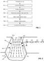
- a priori knowledge on the geometry of the channelmay include e.g. information on the profile in the spanwise direction of the channel. The information may be e.g. the height H above the surface defining the channel in function of y, where y is the distance in the spanwise direction of the channel, see Fig. 2 .
- a channel having a parabolic or trapezoidal profilecan be parameterized with only a few, e.g. two, parameters.
- the method for determining the velocity and, if required, the streamflow in an open channelcomprises the following steps, see Fig. 1 :
- Step 200General set-up
- Fig. 2shows schematically an open channel, which is defined by the boundary surface 201.
- the water flowing in the channeldefines a water line 202a, which is given by the intersection of the water surface 202 with the boundary surface 201 of the channel.
- the water surface 202is also denoted as a free surface.
- the arrows 202billustrate the velocity of the water surface 202 at different locations.
- one camera 203is installed at a place, where it can view a section of the water surface 202, which is moving, and a section, which is non-moving, such as a wall 201a being a part of the boundary surface 201 above the water line 200a or another non-moving object being in contact with the water surface 202.
- the camera 203does not need to be placed above the open channel; it may be placed on one side of the channel, which makes the installation particularly simple and cheap.
- the images acquired by the camera 203can be stored in a memory 205, which may be e.g. an internal memory of the camera 203 or an external hard disk.
- Unit 204 in Fig. 2is a means for transferring the data to the memory 205 and for powering the camera 203. If the memory 205 is an external one, the unit 204 may be connected to the camera 203 by means of a cable, e.g. an Ethernet cable and may be configured such that electrical power is passed via this cable to the camera 203, e.g. in the form of power over Ethernet (PoE).
- a cablee.g. an Ethernet cable
- PoEpower over Ethernet
- the memory 205is connected to processing unit 206, which may be any type of computer which is configured to perform the necessary calculations.
- two cameras 203 and 203bare arranged such that by means of stereo image processing the water level 202a can be determined without making reference to a non-moving object 201a.
- the two cameras 203, 203bmay be arranged such that they view the moving water surface 202 only. This configuration makes the system particularly flexible.
- the cameras 203 and 203bmay be geo-referenced. Depending on the width of the channel this is achieved with a temporary mechanical setup for markers with known world coordinates. For larger channels of the order of 100 m, where the width may prohibit such a mechanical setup, for instance a drone or another aerial vehicle may be employed, which can be seen by a camera 203, 203b, and which can record its position with an accurate DGPS (Differential Global Positioning System).
- DGPSDifferent Global Positioning System
- the cameras 203, 203bare configured such that the velocity is measured for the available field(s) of view. It may or may not cover the entire span-wise direction. In the latter case, a span-wise velocity profile may be fitted to all the available velocity observations. The fitting order depends on the span-wise coverage and the fit obeys the non-slip boundary conditions (i.e. zero velocity) at the channel side walls.
- the two cameras 203 and 203aare connected to unit 204a, which may e.g. a switch box for transferring the data to memory 205 connected to processing unit 206 and for powering the cameras 203 and 203a. It is conceivable that the memory 205 and/or the processing unit 206 are integral parts of the camera 203 and/or 203a.
- a userholds one mobile camera 203b, e.g. a smartphone, such that a section of the water surface 202 and a non-moving object, e.g. part of the wall 201a, is imaged at the same time.
- the camera 203bis arranged such that it views at least one border of the surface 202.
- the camera arrangementoptimizes the trade of between orthogonal view to the channel wall 201a and between orthogonal view to the water surface 202. This optimum is close to 45 deg inclination to the water surface 200. If need be, a spanwise velocity profile is fitted to all the available velocity observations to get the velocity data in the whole spanwise direction.
- a camera modelwhich describes the mathematical relationship between the coordinates of a point in three-dimensional space ("world space”) and its projection onto the image plane.
- Fig. 5shows a point P in 3D space, which is defined in the coordinate system 301 by specific world coordinates (x, y, z), and P', which is the point P imaged by a camera on the image plane.
- the location of P' in the image planemay be given by two Cartesian coordinates ("image coordinates") 302 (i, j).
- image coordinatesimage coordinates
- the mapping of the coordinate system 301 on the coordinate system 302is indicated by arrow 303.
- a camerais calibrated, in which the external parameters, i.e. position and orientation of the camera, and at least one internal parameter, such as the focal distance are obtained.
- the external parametersi.e. position and orientation of the camera
- at least one internal parametersuch as the focal distance
- One usual possibility for determining the calibration parametersis to provide at least 4 reference points with known world coordinates and to evaluate the points imaged by the camera.
- the world coordinates of the reference pointsmay be determined e.g. by means of DGPS (Differential Global Positioning System).
- one or more carriersmay be used which are provided with spots having a bright color, e.g. white, and a circular or any other predetermined shape.
- At least 4 reference points 382 with known world coordinatesare provided for, see Fig. 2 and 3 and imaged by the camera(s).
- a suitable camera modele.g. a pinhole model is used, to fit the coordinates of the reference points in 3D space to their coordinates in the image.
- At least one of the following parametersis to be known a priori: the focal distance, the camera's vertical distance relative to the reference points 382, the camera's horizontal distance relative to the reference points 382.
- the camera's apertureis considered as a point, wherein no lenses are used to focus light.
- the focal lengthis the distance between the image plane and the pinhole.
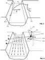
- reference points 382 with known world coordinatesmay be used to calibrate a mobile camera, see Fig. 4 .
- the reference points 382 and the free surface 202are imaged at the same time. In this way, calibration parameters are available for the images based on which the velocity, water line, etc. are to be determined.
- a priori information of the camera's locationis available.
- mobile devicesin particular smartphones, may have a sensor implemented, for instance an accelerometer, which allows a direct measurement of the orientation of the camera 203b relative to the gravity vector 322.
- Fig. 6three perpendicular axes 321 are depicted which define the reference frame 321 of the camera 203b. Its orientation is defined by the angles 321a, 321b, 321c between the gravity vector 322 and the axes of the reference frame 321.
- the calibration methodcan be simplified, as the focal length, or the camera vertical or horizontal distance relative to the reference points 382 does not anymore need to be known a priori, and a set of 4 reference points 382 is fully sufficient to calibrate the pinhole model.
- a calibration procedureis possible by using a body which has a known length scale and which is floating on the surface 202 when the images are acquired.
- This bodymay be e.g. in form of a dumbbell: A bar of definite length has ends which are provided with floating elements, e.g. hollow spheres.
- Step 400Image acquisition
- a camera 203, 203amay be connected e.g. to an Ethernet cable. Energy is supplied to the cameras 203, 203a via PoE. Images are recorded in the memory unit 205 and processed by the processing unit 206.
- the water levelnot only a single image, but a sequence of images are analyzed.
- the number of images acquiredis at least two and may be typically up to 100 or more.
- Usual digital camerascan take 30 frames per second, thus the sequence of images may last a few seconds.
- the imagescan be recorded in gray values.
- a camera with a moderate pixel resolutionmay be sufficient, e.g. 640 ⁇ 480 pixels.
- the scenecan be illuminated with an infrared beamer.
- the cameras 203, 203aare arranged such that they take images from the same scene. Preferably, they are also synchronized such that they take images at the same time. However, a time difference of one frame, e.g. 1/30 sec, can be accepted for later analysis.
- the necessary imagescan be acquired by recording a few seconds of movie, e.g. 5 sec.
- the camera 203bis not fixed.
- the subsequent procedures for water level determination and surface velocity measurementsmay require that position and orientation of the recording camera is sufficiently constant over the time of the sequence and sufficiently identical to the position and the orientation of the camera during calibration. For hand-held smartphone recordings this may not be the case.
- Image processingcan be used to stabilize the image sequence.
- One possible method for such a stabilizationis as follows: The camera 203b is hold such that the images acquired contain a significant part that is not water surface 202, i.e. that contains dry shore scenery 201a and preferably the reference points 382 for calibration or other fixed markers, see Fig. 4 or 6 .
- the softwareis configured to guide the user such that the top and bottom quadrants of the images, i.e. the region at the four corners of the image, contain only dry scenery. From these "dry" quadrants the relative movement between individual frames is measured by an image cross-correlation.
- the cross-correlationcan be facilitated by markers fixed at the shore. Preferably, these markers are reference points 382, which can be also used for calibration.
- the resulting motion vectorsallow a detection and compensation of the inter-frame movement by image registration (transformation of the data into one coordinate system) or simpler by a combination of image rotation and translation. Alternatively, and to save CPU power, only those images which are at approximately the same position and orientation as during calibration are used for further processing.
- Step 500Distinction between "wet” and “dry” image regions
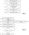
- Fig. 8is a flow chart of the different sub-steps 501-507 of step 500.
- Noisemay be adequately filtered by using for instance a two-dimensional spatial median filter.
- the kernel width of the filteris chosen to be larger than the noise, which may be in the order of 1 or more pixels, and smaller than the advected patterns on the surface 202, which may in the order of 10 or more pixels. For instance a kernel of 5 pixel ⁇ 5 pixel is conceivable.
- the maximum and minimumare determined for each pixel in step 503. This provides image data max(im_f) and min(im_f), respectively.
- step 504the difference between the maximum and the minimum gray values for a given image sequence is taken to get image data De_im.
- a gliding maxima and minimais employed with a kernel width of a given time duration. For instance data are obtained over a period which may last one or more hours, so that the kernel width may be several minutes.
- a typical kernel widthhas e.g. a period of 10 minutes. Any extreme event for a pixel will fade out after that the period given by kernel width and it is gradually replaced by its corresponding gliding average value, see step 505.
- the dry regionmay have relatively sharp transitions between bright and dark areas, e.g. there can be strong local gradients in gray values. Such gradients may be augmented by pixel noise or mechanical camera vibrations. Examples that may lead to such situations are brick walls, rails, trees and other objects, which are non-completely plane flat. Said transitions may lead to an unwanted signal in the "dry" region in the images De_im, such that the water line cannot be determined correctly.
- average image data, Av_imare obtained in step 505 by averaging over the unfiltered image sequence, or, in quasi-continuous mode, by determining the unfiltered gliding average over the image sequence with a specific kernel width, which may be of several minutes.
- step 506the gradient of Av_im is obtained, denoted by grad(Av_im) in Fig. 8 .
- DG_imDe_im - grad(Av_im).
- Step 600Water level determination
- Fig. 9is a flow chart of the different sub-steps 601-608 of step 600.
- the water levelmay be determined as follows: As the geometry of the shore line and the calibration parameters are known, each possible real-world water-level, h, may be mapped into the image space, c(h), see step 601 in Fig. 9 . For plane channel walls this results in straight lines across the image space. However, arbitrary shore line geometries can equally well be mapped onto general curves through the image space. For the calculation the height is discretized, i.e. the calculation is done for an initial value for the height and then repeated by a consecutive increase in the height, see the rhombus "if Lines ⁇ Possible water lines" in Fig. 9 .
- step 602the sum of gray values of all pixels belonging to a particular c(h) is determined.
- a filteris then applied, see step 603.
- a suitable filteris for example a Savitzky-Golay filter, which may be of second order and have a kernel width, w, corresponding to the height of the surface ripples. In one example w is 5 mm.
- the sum of gray valuesmay be plotted versus h, which results in a one-dimensional relation sum(c(h)) ⁇ h, see step 604.
- step 605the derivative is determined, d[sum(c(h))]/dh, which is negative and extremal, where h corresponds to the water level, see step 607 defining that the maximum slope of the function sum(c(h)) is to be found.
- the signal sum(c(h)) as well as the derivative d[sum(d(h))]/dhare filtered with a filter width k, see step 606. If k is not larger than the wave-height at the shore-line, the relevant signal is not filtered out and not biased to any direction, i.e. it can be used as a robust indicator for the water-line position.
- a stereo gaugingmay require that the two cameras look to the same water surface section, i.e. that their views overlap, that preferably the cameras are synchronized in time and that a spatial correspondence between the two camera views can be established, i.e. the angles between the two camera axes is not too large, preferably not larger than 45 degrees.
- An image ⁇is generated by applying a specific filter.
- This filterseparates the moving surface of the image information from the still image information associated with shades, non-moving objects and channel bottom.
- the same filtermay be used as in steps 702, 703 described in more detail below.
- the filtered image ⁇which contains the moving part of the surface only, is projected onto several horizontal planes 202, 202', 202", which each represent potential water levels.
- Each projectionis compared with its corresponding projection from image B ⁇ , which is the filtered image from the second camera.
- image B ⁇which is the filtered image from the second camera.
- Thisis illustrated in Fig. 10 in a simplified way with a scene that contains only two features, a "full" feature F1 and an "empty” feature F2.
- the projections of each featureoverlap only for the projection with the correct height, h.
- the features F1 and F2 as seen in image ⁇are represented by full and empty circles, F1a and F2a, respectively.
- the same features in image B ⁇are represented by full and empty squares, F1b and F2b, respectively.
- the correlation between all the projected gray values from image ⁇ with their corresponding projections from image B ⁇may be measured.
- the comparison between the projections onto the horizontal plane with the correct heightyields a maximum correlation and a minimum mean gray value difference between the corresponding pixels.
- this approachmay be modified by working only on a sub-set of pixels. From image ⁇ a sub-set is projected onto a potential horizontal plane, and from this plane the set is projected onto the virtual image chip of the other camera. Again, the correlation at the positions of the projected sub-set from ⁇ with the pixels from B ⁇ is maximal for the correct height of the horizontal plane. Equivalently, the difference of the two point sets is minimal. Working with a sub-set of pixels reduces the processing time by the ratio of the sizes between the sub-set of the image and the entire image.
- Fig. 11is a flow chart of the different sub-steps 701-705 of step 700.
- FDIVis capable to separate in a robust fashion the moving image contents from the still image contents.
- the functionality of FDIVdoes not require the addition of flow tracers.
- the image sequence taken by a camerais grouped into image triplets, each containing a first image A, a second image B, and a third image C, see step 701.
- the first tripletmay be formed for instance by (I_1, I_2, I_3), the second triplet by (I_2, I_3, I_4), the third triplet by (I_3, I_4, I_5), etc.
- the tripletsare formed in a different way: For instance none of the images of a triplet may be contained in the next triplet, e.g.
- a tripletis formed by (I_i, I_j, I_k), wherein i ⁇ j ⁇ k.
- step 702the absolute difference between A and B and the absolute difference between B and C is formed giving im_1 and im_2, respectively.
- im_1 and im_2are filtered to produce im_1f and im_2f.
- a spatial Gaussian kernelmay be e.g. used as a filter.
- the filter widthis chosen large enough so as to remove difference noise in im_1 and im_2 and to distribute or smear small features in their respective proximities from im_1f to im_2f.
- the filter widthis chosen small enough in order not to completely remove the motion signal in im_1f and im_2f.
- the upper bound for the filter widthmay correspond to the minimal sub-window size that is defined for the following processing step 704.
- the sub-window scale s in units of pixelsis chosen such that it is at least twice d or larger: s ⁇ 2d.
- step 704the spatial shift of patterns from im_1f to im_2f is determined.
- the images im_1f and im_2fare divided into sub-windows with size n ⁇ m ("interrogation window"). Basically, a sub-window of im_1f is compared with the a sub-window of im_2f in order to find a displacement giving the best match between the two sub-windows.
- the image dataare converted to the spectral domain, i.e. Fourier space by using e.g. a Fast Fourier Transform.
- the Fourier transform of im_1fis multiplied with the Fourier conjugate transform of im_2f and then the inverse Fourier transform is applied. This gives for each sub-window an impulse-like function for R(x,y).
- the location of the impulse relative to a sub-window centerrelates to the relative pixel displacement between the sub-windows of im_1f and im_2f.
- the obtained displacement vectors at discrete positionsare finally mapped from pixel space to world space by employing a camera model that is obtained with one of the above described calibration methods.
- im_1f and im_2fmay first be registered into world space, i.e. the image coordinates are converted to the world coordinates. Subsequently, the maximum of the cross-correlation function for each sub-window and the corresponding surface velocity are determined in an analogous way as explained above.
- the latter flavorallows one to choose more flexible aspect ratios for the n*m sized sub-windows, as now the sub-window sides can be chosen exactly parallel and orthogonal to the flow direction.
- image registration in world spaceis more CPU costly than just mapping the velocity vectors from pixel space into world space.
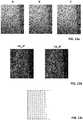
- Fig. 13a-13cshow an example of the images processed by the step 700 for determining the surface velocity.
- the three images A, B, C in Fig. 13ashow part of a river and of a shore at three consecutive instants of time.
- Fig. 13bare the two images im_1f and im_2f obtained after applying steps 702 and 703. Processing of these two images according to steps 704 and 705 gives the velocity of the surface at different locations on the river as shown in Fig. 13c .
- and im_2
- Step 800Streamflow calculation from water-level and surface velocity
- Fig. 12is a flow chart of the different sub-steps 801-805 of step 800.
- the velocity profile along the vertical profileis estimated by integrating a so-called roughness dependent mixing length model from the channel bottom all the way to the water surface.
- the mixing length and kinetic energyare modeled as functions of the height above the bottom and they define the local slope of the velocity profile.
- the initial slope at the channel bottomi.e. the bottom boundary condition, is a function of the so-called roughness velocity and of the bottom roughness height.
- the integrationis iterated to find the correct roughness velocity.
- the water-level and the surface velocity fieldare combined with the model to obtain vertical velocity profiles and successively, the sought after discharge values Q.
- the span-wise direction, y, of the open surface flowis divided into n segments, step 801 in Fig. 12 .
- step 802for each segment the vertical velocity profile is modeled with the boundary conditions of the free surface velocity v(y) as measured (step 705'), the no-slip condition at the bottom (i.e. zero velocity) and the bottom roughness height.
- the average of each velocity profileresults in a bulk velocity vb_(y) in step 803, which multiplied with its corresponding cross sectional area of the segment, yields the discharge Q_s for each span-wise segment, step 804.
- the sum over all Q_sfinally is the discharge Q, step 805.
- the bottom roughness heightaffects both, the water level and the surface velocity of an open surface flow.
- the present methodallows measuring both these quantities independently.
- the surface roughness of the bottommay also be determined by the present method itself, rather than "only" be used for the determination of the resulting discharge.
- three rigidly mounted webcamsmeasured the water-level and the surface velocity field across the entire river at quasi-continuous intervals of 2 seconds. At regular intervals of 10 minutes the information has been combined to estimate the discharge.
- Three cameraswere used to better resolve the entire span wise channel width and the channel wall.
- just one cameramay be used, which has a larger field of view and/or which may be pan, tilt and zoom controllable.
- the methodworked also during the night.
- the methodmay be configured for an all year round usage, i.e. 24 hours x 7 days, to determine the surface velocity and the discharge of free surface flows.
- the addition of flow tracerswas not necessary and a particular constructions for camera mounting over the river was not required. It is enough if the cameras are mounted at the river side and that they can "see" the water surface and the shore-line.
- camerascan be used with controllable pan, tilt and zoom positions. As long as each position can be reliably saved and reached again, calibration can be performed for each position and from here on the method is the same as the above described fixed camera method. However, the number of cameras may be reduced to only one single camera.
- a camera paircan be aligned to view a common section of the open surface to directly determine the water level without the need to see the shore-line.
- the above methodspreferably combined with a suitable way to either stabilize images or to identify those image triplets which are relatively stable, can be implemented into a smartphone application.
- the calibrationneeds to be performed each time, but on the other hand, calibration is also simplified thanks to the use of the accelerometer sensor that is standard even on the cheapest smartphones.
- the measurement locationis automatically determined and it is thus straight forward to use the same application for any number of measurement locations.
- each channel measuring sitewill be equipped with n fixed markers of scale, which may be in the order of 1 cm or more.
- the markers positions relative to each other and relative to the channel geometryneed to be measured once. Also the channel geometry needs to be measured once.
- the computer program for the mobile device(“app") is designed to guide the user towards an approximate position relative to the channel and to the calibration marks for calibration.
- the actual recordingoccurs over a time of period which is in the order of 1 sec or more. This is enough to determine water level and water surface velocity, from which the discharge can be determined.
- the method for determining the velocity of a moving water surfaceis applicable for any kind of fluid, not only water.
- the methodmay be performed without the steps for determining the fluid level and/or discharge.
- Illumination by means of a lightening devicee.g. an infrared beamer is generally conceivable in cases, where the environmental light is insufficient, e.g. also in an closed environment such as a sewage system.
Landscapes
- Physics & Mathematics (AREA)
- General Physics & Mathematics (AREA)
- Engineering & Computer Science (AREA)
- Fluid Mechanics (AREA)
- Aviation & Aerospace Engineering (AREA)
- Multimedia (AREA)
- Computer Vision & Pattern Recognition (AREA)
- Theoretical Computer Science (AREA)
- Radar, Positioning & Navigation (AREA)
- Remote Sensing (AREA)
- Hydrology & Water Resources (AREA)
- Life Sciences & Earth Sciences (AREA)
- Electromagnetism (AREA)
- Thermal Sciences (AREA)
- Length Measuring Devices By Optical Means (AREA)
Description
- The present invention relates to a method and a system for determining the velocity of a moving fluid surface by means of at least one camera.
- Measuring the velocity of a flow is needed in many applications, e.g. when determining the streamflow in an open channel. Such measurements are for instance important in the realm of irrigation, drinking water supply, hydroelectric power production, flood control, reservoir control, sewage systems, preservation of ecosystems, etc. Streamflows can occur in many different types of structures, natural courses, artificial channels, furrows etc. All of them are open-channel flows, i.e. flows having a free surface.
- There are many different systems available for measuring the velocity. Systems which are image based possess the advantage that there is no need of expensive installations and they offer more flexibility than other non-intrusive measurements systems.
- A long established technique for velocity measurements is the technique of Particle Image Velocimetry (PIV); see e.g.R.J. Adrian, 1991, "Particle-imaging techniques for experimental fluid mechanics." Annual Review of Fluid Mechanics 23, 261-304. PIV is since the work ofIchiro Fujita, Marian Muste, and Anton Kruger (1998, "Large-scale particle image velocimetry for flow analysis in hydraulic engineering applications." Journal of Hydraulic Research 36 (3): 397-414) also known of being applied to large scale free surface flows of flumes or open channels. This flavor of PIV is known to the hydraulic research and engineering community as Large Scale PIV (LSPIV), see e.g.
- Muste, M., I. Fujita, and A. Hauet. 2008. "Large-Scale Particle Image Velocimetry for Measurements in Riverine Environments." Water Resources Research 44 (4), and
- Muste, M., H.-C. Ho, and D. Kim. 2011. "Considerations on Direct Stream Flow Measurements Using Video Imagery: Outlook and Research Needs." Journal of Hydro-Environment Research 5 (4): 289-300.
- Recent examples of LSPIV being applied to river flows are described e.g. in
- patent application
WO 2014/013064 A1 , - Kim, Y., M. Muste, A. Hauet, W. F. Krajewski, A. Kruger, and A. Bradley. 2008. "Stream Discharge Using Mobile Large-Scale Particle Image Velocimetry: A Proof of Concept." Water Resources Research 44 (9),
- Dramais, Guillaume, Jérôme Le Coz, Benoît Camenen, and Alexandre Hauet. 2011. "Advantages of a Mobile LSPIV Method for Measuring Flood Discharges and Improving Stage-discharge Curves." Journal of Hydro-Environment Research 5 (4): 301-12,
- Tsubaki, Ryota, Ichiro Fujita, and Shiho Tsutsumi. 2011. "Measurement of the Flood Discharge of a Small-Sized River Using an Existing Digital Video Recording System." Journal of Hydro-Environment Research 5 (4): 313-21,
- Creutin, J. D., M. Muste, A. A. Bradley, S. C. Kim, and A. Kruger. 2003. "River gauging using PIV techniques: a proof of concept experiment on the Iowa River." Journal of Hydrology 277: 182-194, and
- Le Coz, J., A. Hauet, G. Pierrefeu, G. Dramais, and B. Camenen. 2010. "Performance of image-based velocimetry (LSPIV) applied to flash-flood discharge measurements in Mediterranean rivers." Journal of Hydrology 394: 42-52.
- All these mentioned PIV methods have in common that they require having a well detectable flow tracer of some kind. However, the use of natural or artificial tracers possesses some complications to practically measure the velocity, since the tracers are not generally present and/or cannot be added permanently and continuously.
- In the method disclosed in
WO 2014/013064 A1 the velocity of tracers is determined by subtracting two images to obtain a composite image and by setting a threshold to suppress the non-moving zones. This has the effect that information on moving patterns of the fluid surface is suppressed as well. Furthermore, since the displacement of the tracers is determined within the same composite image, their direction of movement is indefinite. - The depth of water can also be estimated using images. In
WO 2014/013064 A1 it is proposed to analyze pixel colorimeter to determine the water level. However, using pixel colorimeter can possess some difficulties for analyzing images with poor light conditions. The method described inWO 2014/013064 A1 also needs at least one visual reference object being partially immersed in water, which constrains the places where the system can be installed. In addition, at least 6 reference points which have to be geo-referenced are needed for the camera calibration, in which the external parameters (i.e. position and orientation and at least the internal parameter focal distance) are obtained. - The patent application
WO 01/51897 A1 - The patent
US 6 098 029 refers to a method of measuring the height of a liquid surface by using plates. - The patent application
JP 2001 041803 A - The patent application
JP 2007 223879 A - The patent application
WO 2008/110909 A2 discloses a method for measuring the peak flow dicharges by means of radar sensors. - The patent application
US 2006/0126933 A1 refers to a foreground detection using intrinsic images. No application is provided in the field of determining the velocity of a moving fluid surface. - It is an aim of the present invention to provide for a method and a system which allow determining in a reliable manner the velocity of a moving fluid surface without need of adding flow tracers.
- This aim is achieved by the method and the system as defined in claims 1 and 13, respectively. The further claims specify preferred embodiments of the device and the system according to the invention as well as computer program and a data medium.
- The invention is explained in the following by means of exemplary embodiments with reference to Figures. In the drawings:
Fig. 1 is a flowchart of steps of a method according to an embodiment of the invention;Fig. 2 shows a schematic view of a first embodiment of a system for performing the method illustrated inFig. 1 ;Fig. 3 shows a schematic view of a second embodiment of a system for performing the method illustrated inFig. 1 ;Fig. 4 shows a schematic view of a third embodiment of a system for performing the method illustrated inFig. 1 ;Fig. 5 shows a schematic view of the relationship between world and camera coordinates;Fig. 6 shows a schematic view of an embodiment for calibrating a camera;Fig. 7 shows a schematic view of another embodiment for calibrating a camera;Fig. 8 is a flowchart of the sub-steps ofstep 500 of the method ofFig. 1 , wherein in the images acquired "wet" and "dry" parts of the scene are distinguished from each other;Fig. 9 is a flowchart of the sub-steps ofstep 600 of the method ofFig. 1 , wherein the water level is determined based on the images acquired;Fig. 10 is a schematic illustration of the method for determining the water level for the embodiment ofFig. 3 ;Fig. 11 is a flowchart of the sub-steps ofstep 700 of the method ofFig. 1 , wherein the surface flow velocity is determined;Fig. 12 is a flowchart of the sub-steps ofstep 800 of the method ofFig. 1 , wherein the discharge is determined, andFig. 13a-13c refer to an example of three images, which are processed according to themethod step 700 ofFig. 1 .- The following described embodiments concern a method and a system for obtaining the surface velocity field and, if required, the fluid level in an open channel by means of one or more digital cameras. The measured quantities may be combined with a priori knowledge on the geometry of the channel to determine e.g. the discharge or other quantities. The embodiments are described with respect to flowing water, but they are applicable also for other flowing fluids.
- An open channel is a conduit with a free surface, i.e. the fluid flowing in the channel has a free surface (e.g. river, stream, artificial channel, furrow, etc.). Streamflow or discharge, Q, is defined as the volumetric rate of flow of the fluid in the channel and is given for instance in units of cubic meter per second. A priori knowledge on the geometry of the channel may include e.g. information on the profile in the spanwise direction of the channel. The information may be e.g. the height H above the surface defining the channel in function of y, where y is the distance in the spanwise direction of the channel, see
Fig. 2 . In a simple case, where the channel can be considered as having a rectangular profile, information on the distance between the side walls limiting the channel and its depth may be sufficient. Similarly, a channel having a parabolic or trapezoidal profile can be parameterized with only a few, e.g. two, parameters. - The method for determining the velocity and, if required, the streamflow in an open channel comprises the following steps, see
Fig. 1 : - Step 200: Set-up of the hardware, in particular installation of at least one camera. The camera may be any imaging device which is suitable to provide for a sequence of digital images. Apart from usual digital cameras, it is conceivable to use mobile phones, such as smartphones, or webcameras.
- Step 300: Calibration of the camera(s).
- Step 400: Image acquisition.
- Step 500: Processing of the images acquired in order to distinct between "wet" and "dry" parts of the scene.
- Step 600: Water level determination based on the images acquired.
- Step 700: Image processing to determine the surface flow velocity.
- Step 800: Streamflow calculation.
- In the following the steps 200-800 are explained in more details in relation to three camera configurations C1, C2, C3:
- Camera configuration C1: usage of a
single camera 203, which is fixed, seeFig. 2 , - Camera configuration C2: usage of two
cameras Fig. 3 . - Camera configuration C3: usage of a
mobile device 203b, e.g. a mobile phone, hold by a user, seeFig. 4 . Fig. 2 shows schematically an open channel, which is defined by theboundary surface 201. The water flowing in the channel defines awater line 202a, which is given by the intersection of thewater surface 202 with theboundary surface 201 of the channel. As the channel is open, thewater surface 202 is also denoted as a free surface. Thearrows 202b illustrate the velocity of thewater surface 202 at different locations.- In the camera configuration C1 one
camera 203 is installed at a place, where it can view a section of thewater surface 202, which is moving, and a section, which is non-moving, such as awall 201a being a part of theboundary surface 201 above the water line 200a or another non-moving object being in contact with thewater surface 202. Thecamera 203 does not need to be placed above the open channel; it may be placed on one side of the channel, which makes the installation particularly simple and cheap. - The images acquired by the
camera 203 can be stored in amemory 205, which may be e.g. an internal memory of thecamera 203 or an external hard disk.Unit 204 inFig. 2 is a means for transferring the data to thememory 205 and for powering thecamera 203. If thememory 205 is an external one, theunit 204 may be connected to thecamera 203 by means of a cable, e.g. an Ethernet cable and may be configured such that electrical power is passed via this cable to thecamera 203, e.g. in the form of power over Ethernet (PoE). - For processing the images stored, the
memory 205 is connected toprocessing unit 206, which may be any type of computer which is configured to perform the necessary calculations. - In the configuration C2 shown in
Fig. 3 twocameras water level 202a can be determined without making reference to anon-moving object 201a. Thus, the twocameras water surface 202 only. This configuration makes the system particularly flexible. - The
cameras camera - The
cameras - The two
cameras unit 204a, which may e.g. a switch box for transferring the data tomemory 205 connected toprocessing unit 206 and for powering thecameras memory 205 and/or theprocessing unit 206 are integral parts of thecamera 203 and/or 203a. - In the camera configuration C3 shown in
Fig. 4 a user holds onemobile camera 203b, e.g. a smartphone, such that a section of thewater surface 202 and a non-moving object, e.g. part of thewall 201a, is imaged at the same time. If the velocity is to be determined along the channel in the whole spanwise direction, thecamera 203b is arranged such that it views at least one border of thesurface 202. Preferably, the camera arrangement optimizes the trade of between orthogonal view to thechannel wall 201a and between orthogonal view to thewater surface 202. This optimum is close to 45 deg inclination to thewater surface 200. If need be, a spanwise velocity profile is fitted to all the available velocity observations to get the velocity data in the whole spanwise direction. - For determining the desired quantities (flow velocity, discharge, etc.) a camera model is used which describes the mathematical relationship between the coordinates of a point in three-dimensional space ("world space") and its projection onto the image plane. As an example
Fig. 5 shows a point P in 3D space, which is defined in the coordinatesystem 301 by specific world coordinates (x, y, z), and P', which is the point P imaged by a camera on the image plane. The location of P' in the image plane may be given by two Cartesian coordinates ("image coordinates") 302 (i, j). The mapping of the coordinatesystem 301 on the coordinatesystem 302 is indicated byarrow 303. - In order to fit a camera model to the camera view, a camera is calibrated, in which the external parameters, i.e. position and orientation of the camera, and at least one internal parameter, such as the focal distance are obtained. In the following these external and internal parameters are denoted as "calibration parameters".
- One usual possibility for determining the calibration parameters is to provide at least 4 reference points with known world coordinates and to evaluate the points imaged by the camera. For applications, where the scale s of the field of view is large, e.g. s is much larger than 1 m, the world coordinates of the reference points may be determined e.g. by means of DGPS (Differential Global Positioning System).
- As reference points e.g. fixed makers can be used, which are positioned at definite locations at the channel and which are configured to be imaged in a way clearly distinguishable from the background. For this purpose, one or more carriers may be used which are provided with spots having a bright color, e.g. white, and a circular or any other predetermined shape.
- In the following various examples of calibration methods are explained with respect to
Fig. 2 ,3 ,4 ,6 and7 : - For one or more fixed cameras, as in the configuration C1 and C2, at least 4
reference points 382 with known world coordinates are provided for, seeFig. 2 and3 and imaged by the camera(s). A suitable camera model, e.g. a pinhole model is used, to fit the coordinates of the reference points in 3D space to their coordinates in the image. - In case that there are 4
reference points 382 only, at least one of the following parameters is to be known a priori: the focal distance, the camera's vertical distance relative to thereference points 382, the camera's horizontal distance relative to the reference points 382. - In the pinhole model the camera's aperture is considered as a point, wherein no lenses are used to focus light. The focal length is the distance between the image plane and the pinhole.
- In a similar way at least 4
reference points 382 with known world coordinates may be used to calibrate a mobile camera, seeFig. 4 . Preferably, thereference points 382 and thefree surface 202 are imaged at the same time. In this way, calibration parameters are available for the images based on which the velocity, water line, etc. are to be determined. - It is conceivable that a priori information of the camera's location is available. For instance mobile devices, in particular smartphones, may have a sensor implemented, for instance an accelerometer, which allows a direct measurement of the orientation of the
camera 203b relative to thegravity vector 322. InFig. 6 threeperpendicular axes 321 are depicted which define thereference frame 321 of thecamera 203b. Its orientation is defined by theangles gravity vector 322 and the axes of thereference frame 321. By using the information on the camera's orientation, two external parameters do not need to be fitted by the camera model. Thus, the calibration method can be simplified, as the focal length, or the camera vertical or horizontal distance relative to thereference points 382 does not anymore need to be known a priori, and a set of 4reference points 382 is fully sufficient to calibrate the pinhole model. - The methods for calibration explained so far have in common that they yield the camera's position relative to a fixed frame, in which the geometry of the channel is defined. The following methods yield the camera position relative to the free surface only.
- A calibration procedure is possible by using a body which has a known length scale and which is floating on the
surface 202 when the images are acquired. This body may be e.g. in form of a dumbbell: A bar of definite length has ends which are provided with floating elements, e.g. hollow spheres. - In the configuration C1 and C2 a
camera cameras memory unit 205 and processed by theprocessing unit 206. - For determining for instance the water level not only a single image, but a sequence of images are analyzed. The number of images acquired is at least two and may be typically up to 100 or more. Usual digital cameras can take 30 frames per second, thus the sequence of images may last a few seconds.
- The images can be recorded in gray values. Depending on the application, a camera with a moderate pixel resolution may be sufficient, e.g. 640×480 pixels.
- During night the scene can be illuminated with an infrared beamer.
- For allowing a stereo gauging in the configuration C2 the
cameras - In the camera configuration C3 the necessary images can be acquired by recording a few seconds of movie, e.g. 5 sec. In this configuration C3 the
camera 203b is not fixed. The subsequent procedures for water level determination and surface velocity measurements may require that position and orientation of the recording camera is sufficiently constant over the time of the sequence and sufficiently identical to the position and the orientation of the camera during calibration. For hand-held smartphone recordings this may not be the case. Image processing can be used to stabilize the image sequence. One possible method for such a stabilization is as follows:
Thecamera 203b is hold such that the images acquired contain a significant part that is notwater surface 202, i.e. that containsdry shore scenery 201a and preferably thereference points 382 for calibration or other fixed markers, seeFig. 4 or6 . In the smartphone application described below, the software is configured to guide the user such that the top and bottom quadrants of the images, i.e. the region at the four corners of the image, contain only dry scenery. From these "dry" quadrants the relative movement between individual frames is measured by an image cross-correlation. The cross-correlation can be facilitated by markers fixed at the shore. Preferably, these markers arereference points 382, which can be also used for calibration. The resulting motion vectors allow a detection and compensation of the inter-frame movement by image registration (transformation of the data into one coordinate system) or simpler by a combination of image rotation and translation. Alternatively, and to save CPU power, only those images which are at approximately the same position and orientation as during calibration are used for further processing. Fig. 8 is a flow chart of the different sub-steps 501-507 ofstep 500.- Analyzing not only a single image, but a sequence of images allows discriminating between the "wet"
region 202 of the image (i.e. flowing water) and the "dry"region 201a, which views non-moving scenery (e.g. the shore, rocks, part of a bridge pillar, etc.). Any pixels looking to the "dry" parts of the scene will experience little change in their gray values, whereas "wet" parts are subject to constant change, caused by little waves and surface perturbations of the flow. In an ideal camera and in an ideal illumination situation the pixel change in the dry region would be zero. However, in reality, there exists a finite noise level due to non-constant electronic camera gain, due to changing light situations (e.g. when clouds are crossing the sky) as well as due to mechanical vibrations. The electronic noise increases in dark situations, especially during the night when additional light sources like e.g. infra-red diodes are necessary for the cameras to see anything at all. - Thus, after reading the images out from the memory,
step 501 inFig. 8 , they are filtered to get data im_f,step 502. Noise may be adequately filtered by using for instance a two-dimensional spatial median filter. The kernel width of the filter is chosen to be larger than the noise, which may be in the order of 1 or more pixels, and smaller than the advected patterns on thesurface 202, which may in the order of 10 or more pixels. For instance a kernel of 5 pixel × 5 pixel is conceivable. - In order to obtain a scalar measure of the change of each pixel gray value over a defined sequence, the maximum and minimum are determined for each pixel in
step 503. This provides image data max(im_f) and min(im_f), respectively. - In
step 504, the difference between the maximum and the minimum gray values for a given image sequence is taken to get image data De_im. In quasi-continuous mode, in which data are to be obtained for a longer period of time, a gliding maxima and minima is employed with a kernel width of a given time duration. For instance data are obtained over a period which may last one or more hours, so that the kernel width may be several minutes. A typical kernel width has e.g. a period of 10 minutes. Any extreme event for a pixel will fade out after that the period given by kernel width and it is gradually replaced by its corresponding gliding average value, seestep 505. - Depending on the type of scene imaged, additional image processing may be applied to filter out artifacts. For instance the dry region may have relatively sharp transitions between bright and dark areas, e.g. there can be strong local gradients in gray values. Such gradients may be augmented by pixel noise or mechanical camera vibrations. Examples that may lead to such situations are brick walls, rails, trees and other objects, which are non-completely plane flat. Said transitions may lead to an unwanted signal in the "dry" region in the images De_im, such that the water line cannot be determined correctly. To deal with such artifacts, average image data, Av_im, are obtained in
step 505 by averaging over the unfiltered image sequence, or, in quasi-continuous mode, by determining the unfiltered gliding average over the image sequence with a specific kernel width, which may be of several minutes. - In
step 506, the gradient of Av_im is obtained, denoted by grad(Av_im) inFig. 8 . Instep 507, this gradient is subtracted from the "max-min difference", De_im, in order to obtain processed image data DG_im, i.e. DG_im = De_im - grad(Av_im). The distinction between wet and dry regions is enhanced by using the processed image data DG_im, since the artifacts mentioned above are at least partially filtered out. Fig. 9 is a flow chart of the different sub-steps 601-608 ofstep 600.- For the camera configuration C1 or C3 the water level may be determined as follows:
As the geometry of the shore line and the calibration parameters are known, each possible real-world water-level, h, may be mapped into the image space, c(h), seestep 601 inFig. 9 . For plane channel walls this results in straight lines across the image space. However, arbitrary shore line geometries can equally well be mapped onto general curves through the image space. For the calculation the height is discretized, i.e. the calculation is done for an initial value for the height and then repeated by a consecutive increase in the height, see the rhombus "if Lines < Possible water lines" inFig. 9 . - In
step 602, the sum of gray values of all pixels belonging to a particular c(h) is determined. Preferably, a filter is then applied, seestep 603. A suitable filter is for example a Savitzky-Golay filter, which may be of second order and have a kernel width, w, corresponding to the height of the surface ripples. In one example w is 5 mm. - The sum of gray values may be plotted versus h, which results in a one-dimensional relation sum(c(h)) ↔ h, see
step 604. - In
step 605, the derivative is determined, d[sum(c(h))]/dh, which is negative and extremal, where h corresponds to the water level, seestep 607 defining that the maximum slope of the function sum(c(h)) is to be found. Preferably before thisstep 607, the signal sum(c(h)) as well as the derivative d[sum(d(h))]/dh are filtered with a filter width k, seestep 606. If k is not larger than the wave-height at the shore-line, the relevant signal is not filtered out and not biased to any direction, i.e. it can be used as a robust indicator for the water-line position. - For the camera configuration C2 a different approach may be used to determine the water level.
- A stereo gauging may require that the two cameras look to the same water surface section, i.e. that their views overlap, that preferably the cameras are synchronized in time and that a spatial correspondence between the two camera views can be established, i.e. the angles between the two camera axes is not too large, preferably not larger than 45 degrees.
- An image à is generated by applying a specific filter. This filter separates the moving surface of the image information from the still image information associated with shades, non-moving objects and channel bottom. The same filter may be used as in
steps - The filtered image Ã, which contains the moving part of the surface only, is projected onto several
horizontal planes Fig. 10 in a simplified way with a scene that contains only two features, a "full" feature F1 and an "empty" feature F2. The projections of each feature overlap only for the projection with the correct height, h. InFig. 10 the features F1 and F2 as seen in image à are represented by full and empty circles, F1a and F2a, respectively. The same features in image B̃ are represented by full and empty squares, F1b and F2b, respectively. As can be seen, when projecting F1a, F2a, F1b, F2b onto a plane having an incorrect height,e.g. plane 202', 202", the projection of F1a is separated from F1b and the projection of F2a is separated from F2b. An overlap of F1a and F1b as well as of F2a and F2b is given when they are projected on theplane 202 having the correct height. - In order to quantify the quality of the overlap generally, the correlation between all the projected gray values from image à with their corresponding projections from image B̃ may be measured. Thus, the comparison between the projections onto the horizontal plane with the correct height yields a maximum correlation and a minimum mean gray value difference between the corresponding pixels. These extreme points thus identify the correct water level.
- In order to reduce the necessary computer processing time, this approach may be modified by working only on a sub-set of pixels. From image à a sub-set is projected onto a potential horizontal plane, and from this plane the set is projected onto the virtual image chip of the other camera. Again, the correlation at the positions of the projected sub-set from à with the pixels from B̃ is maximal for the correct height of the horizontal plane. Equivalently, the difference of the two point sets is minimal. Working with a sub-set of pixels reduces the processing time by the ratio of the sizes between the sub-set of the image and the entire image.
Fig. 11 is a flow chart of the different sub-steps 701-705 ofstep 700.- The method as explained in the following allows the surface velocity field to be measured. This method will also be designated as Filtered Delta Image Velocimetry (FDIV).
- If the bottom of the channel is visible through the water phase, if shades or scenery reflections are visible on the water surface, and/or if non-moving objects like standing waves or solid rocks or bridge pillars "contaminate" the image scene, standard PIV does not work, as it would measure some value between zero and the actual surface velocity.
- FDIV is capable to separate in a robust fashion the moving image contents from the still image contents. The functionality of FDIV does not require the addition of flow tracers.
- The image sequence taken by a camera is grouped into image triplets, each containing a first image A, a second image B, and a third image C, see
step 701. - For instance at time t_1 an image I_1 is acquired, at a later time t_2 an image I_2, at a further later time t_3 an image I_3, etc. This gives a series of images I_1, I_2, I_3, etc. The first triplet may be formed for instance by (I_1, I_2, I_3), the second triplet by (I_2, I_3, I_4), the third triplet by (I_3, I_4, I_5), etc. However, it is conceivable that the triplets are formed in a different way: For instance none of the images of a triplet may be contained in the next triplet, e.g. (I_1, I_2, I_3), (I_4, I_5, I_6), and/or there may be gaps within a triplet, e.g. (I_1, I_3, I_5). Each triplet will give data on the velocity field for one instant of time. In general, a triplet is formed by (I_i, I_j, I_k), wherein i<j<k.
- In the following processing of one triplet (A, B, C) is explained.
- In
step 702, the absolute difference between A and B and the absolute difference between B and C is formed giving im_1 and im_2, respectively. - In
step 703, im_1 and im_2 are filtered to produce im_1f and im_2f. A spatial Gaussian kernel may be e.g. used as a filter. The filter width is chosen large enough so as to remove difference noise in im_1 and im_2 and to distribute or smear small features in their respective proximities from im_1f to im_2f. On the other hand, the filter width is chosen small enough in order not to completely remove the motion signal in im_1f and im_2f. The upper bound for the filter width may correspond to the minimal sub-window size that is defined for the followingprocessing step 704. In order to detect motion displacement of scale d in units of pixels, the sub-window scale s in units of pixels is chosen such that it is at least twice d or larger: s ≥ 2d. - In
step 704, the spatial shift of patterns from im_1f to im_2f is determined. - The images im_1f and im_2f are divided into sub-windows with size n×m ("interrogation window"). Basically, a sub-window of im_1f is compared with the a sub-window of im_2f in order to find a displacement giving the best match between the two sub-windows. The degree of match may be determined by means of the cross-correlation function of im_1f and im_2f:

- In order to calculate the cross-correlation function, the image data are converted to the spectral domain, i.e. Fourier space by using e.g. a Fast Fourier Transform.
- The Fourier transform of im_1f is multiplied with the Fourier conjugate transform of im_2f and then the inverse Fourier transform is applied. This gives for each sub-window an impulse-like function for R(x,y). The location of the impulse relative to a sub-window center relates to the relative pixel displacement between the sub-windows of im_1f and im_2f. The obtained displacement vectors at discrete positions are finally mapped from pixel space to world space by employing a camera model that is obtained with one of the above described calibration methods.
- Alternatively, im_1f and im_2f may first be registered into world space, i.e. the image coordinates are converted to the world coordinates. Subsequently, the maximum of the cross-correlation function for each sub-window and the corresponding surface velocity are determined in an analogous way as explained above. The latter flavor allows one to choose more flexible aspect ratios for the n*m sized sub-windows, as now the sub-window sides can be chosen exactly parallel and orthogonal to the flow direction. On the other hand image registration in world space is more CPU costly than just mapping the velocity vectors from pixel space into world space.
Fig. 13a-13c show an example of the images processed by thestep 700 for determining the surface velocity. The three images A, B, C inFig. 13a show part of a river and of a shore at three consecutive instants of time.Fig. 13b are the two images im_1f and im_2f obtained after applyingsteps steps Fig. 13c .- In an alternative method of
steps 701 and 702 a group of four different images of the image sequence is taken to determine the difference: im_1 = |A-B_1| and im_2= |B_2-C|, where B_2 is an image acquired after the image A and preferably also B_1 have been acquired. Fig. 12 is a flow chart of the different sub-steps 801-805 ofstep 800.- In order to determine the discharge Q, information on the velocity profile along the vertical direction is needed. Such information may be obtained by using a model, for instance a roughness dependent mixing length model as suggested byR. Absi, "A roughness and time dependent mixing length equation", Journal of Hydraulic, Coastal and Environmental Engineering, Japan Society of Civil Engineers, Vol. 62, 2006, pages 437-446. In this model, the velocity profile along the vertical profile is estimated by integrating a so-called roughness dependent mixing length model from the channel bottom all the way to the water surface. The mixing length and kinetic energy are modeled as functions of the height above the bottom and they define the local slope of the velocity profile. The initial slope at the channel bottom, i.e. the bottom boundary condition, is a function of the so-called roughness velocity and of the bottom roughness height. In order to meet the water surface, i.e. to satisfy the top boundary condition, the integration is iterated to find the correct roughness velocity.
- The water-level and the surface velocity field are combined with the model to obtain vertical velocity profiles and successively, the sought after discharge values Q.
- The span-wise direction, y, of the open surface flow is divided into n segments,
step 801 inFig. 12 . - In
step 802, for each segment the vertical velocity profile is modeled with the boundary conditions of the free surface velocity v(y) as measured (step 705'), the no-slip condition at the bottom (i.e. zero velocity) and the bottom roughness height. The average of each velocity profile results in a bulk velocity vb_(y) instep 803, which multiplied with its corresponding cross sectional area of the segment, yields the discharge Q_s for each span-wise segment,step 804. The sum over all Q_s finally is the discharge Q,step 805. - The bottom roughness height affects both, the water level and the surface velocity of an open surface flow. The present method allows measuring both these quantities independently. For stream sections with sufficiently little change in stream-wise direction, the surface roughness of the bottom may also be determined by the present method itself, rather than "only" be used for the determination of the resulting discharge.
- In the following specific applications of the method are described in more detail:
- In one application, three rigidly mounted webcams measured the water-level and the surface velocity field across the entire river at quasi-continuous intervals of 2 seconds. At regular intervals of 10 minutes the information has been combined to estimate the discharge. Three cameras were used to better resolve the entire span wise channel width and the channel wall. Alternatively, just one camera may be used, which has a larger field of view and/or which may be pan, tilt and zoom controllable.
- By using e.g. a 70 Watt infra-red beamer for illumination, the method worked also during the night. Thus, the method may be configured for an all year round usage, i.e. 24 hours x 7 days, to determine the surface velocity and the discharge of free surface flows. The addition of flow tracers was not necessary and a particular constructions for camera mounting over the river was not required. It is enough if the cameras are mounted at the river side and that they can "see" the water surface and the shore-line.
- For additional flexibility instead of web cameras non-movably arranged, cameras can be used with controllable pan, tilt and zoom positions. As long as each position can be reliably saved and reached again, calibration can be performed for each position and from here on the method is the same as the above described fixed camera method. However, the number of cameras may be reduced to only one single camera.
- With the above described method of stereo-gauging, see
Fig. 3 , a camera pair can be aligned to view a common section of the open surface to directly determine the water level without the need to see the shore-line. - With cameras that allow controlling pan, tilting and zooming positions, it is possible to successively scan the entire width of the surface flow. Thus, it is possible to measure with just 2 cameras water-level and surface velocity of the entire surface flow, which allows one to determine the discharge independent of the shore-line visibility.
- The above methods, preferably combined with a suitable way to either stabilize images or to identify those image triplets which are relatively stable, can be implemented into a smartphone application. The calibration needs to be performed each time, but on the other hand, calibration is also simplified thanks to the use of the accelerometer sensor that is standard even on the cheapest smartphones. In addition, via GPS, also standard on all smartphones, the measurement location is automatically determined and it is thus straight forward to use the same application for any number of measurement locations.
- For calibration, each channel measuring site will be equipped with n fixed markers of scale, which may be in the order of 1 cm or more. The markers positions relative to each other and relative to the channel geometry need to be measured once. Also the channel geometry needs to be measured once. The computer program for the mobile device ("app") is designed to guide the user towards an approximate position relative to the channel and to the calibration marks for calibration. The actual recording occurs over a time of period which is in the order of 1 sec or more. This is enough to determine water level and water surface velocity, from which the discharge can be determined.
- The method and system described so far have various advantages:
- The measurement does not require the addition of flow tracers nor the presence of permanent structures in the fluid. Measurement is possible also in conditions where non-moving shades, reflections, standing waves, or solid objects are a significant part of the image.
- It is sufficient to acquire monochromatic images, e.g. gray images. Such images are better suited for difficult light conditions than color images.
- Measurement is possible even during night by using e.g. an infrared beamer.
- Water level determination is based on the separation of wet and dry parts of the image via analysis of a sequence of images rather than one single image.
- The calibration uses a minimum of 4 reference points in the case of a mobile camera with a fixed focal length; and, if the viewing angle of the camera relative to the horizontal plane is available, only 2 points are needed.
- Measurement can be done also by means of a mobile camera, e.g. a camera in a mobile phone.
- The method and system is applicable in environmental, hydraulic, hydrological and other areas.
- From the preceding description, many modifications are available to the skilled person without departing from the scope of the invention, which is defined in the claims.
- The method for determining the velocity of a moving water surface is applicable for any kind of fluid, not only water.
- Depending on the application, the method may be performed without the steps for determining the fluid level and/or discharge.
- Illumination by means of a lightening device, e.g. an infrared beamer is generally conceivable in cases, where the environmental light is insufficient, e.g. also in an closed environment such as a sewage system.

Claims (18)
- A method for determining the velocity (202b) of a moving fluid surface (202), comprising the following steps S1 to S5:S1) taking a sequence of images of the moving fluid surface by at least one camera (203, 203a, 203b);S2) comparing a first image from the sequence taken at time t1 with a second image from the sequence taken at time t2 in order to distinguish moving patterns of the fluid surface from non-moving parts and to obtain a first processed image (im_1f) comprising the moving patterns, wherein t2 is later than t1;S3) comparing a third image from the sequence taken at time t3 with a fourth image from the sequence taken at time t4 in order to distinguish moving patterns of the fluid surface from non-moving parts and to obtain a second processed image (im_2f) comprising the moving patterns, wherein t3 and t4 are later than t1 and wherein t4 is later than t3;S4) comparing the first and second processed images in order to determine the spatial displacements of the moving patterns; andS5) determining from the spatial displacements the velocity.
- The method of claim 1, wherein, for obtaining the first processed image (im_1f) and/or the second processed image (im _2f) in step S2 and/or S3, at least one of the following steps is performed:- the second image is used as the third image, so that t2 corresponds to t3,- the first, second, third and fourth images are provided as monochromatic images,- the absolute difference between the first image and the second image is built and preferably filtered by applying a bandpass filter, in particular a Gaussian filter,- the absolute difference between the third image and the fourth image is built and preferably filtered by applying a bandpass filter, in particular a Gaussian filter.
- The method of claim 1 or 2, wherein in step S4 spatial displacements are determined by evaluating a cross-correlation between subwindows of the first and second processed images (im_1f, im_2f).
- The method according to any one of the preceding claims, wherein the fluid flows through an open channel (201), the method further comprising at least one of the following steps:- determining the spanwise profile of streamwise velocity (v(y)),- determining the level of the fluid surface (202),- determining the discharge (Q) of the fluid through the channel.
- The method of claim 4, further comprising the following steps (500, 600) for determining the level of the fluid surface (202) :- comparing at least two images from the sequence taken at different times in order to obtain a comparative image (DG_im) distinguishing the fluid parts imaged from the non-fluid parts imaged,- mapping a boundary of a possible transition from the fluid parts to the non-fluid parts defined in the world coordinates (x, y, z) at different heights to the image coordinates (i, j) of the at least one camera (203, 203b) by means of a camera model (303) in order to get mapped boundaries,- comparing the mapped boundaries with the imaged boundary in the comparative image (DG_im) defining the transition from the fluid parts to the non-fluid parts, and- determining out of the mapped boundaries the boundary which best fits to the imaged boundary.
- The method of claim 5, wherein at least one of the following steps is performed:- determining the extreme values (max(im_f), min(im_f)) of corresponding pixels in the at least two images or in at least two processed images (im_1f, im_2f) obtained in steps S2 and S3 and building the difference between the extreme values to get a difference image (De_im), which comprises pixels having a value above a given threshold defining a fluid part and pixels having a value below the threshold defining a non-fluid part,- building the gradient of the average over the at least two images (grad(Av_im)) and subtracting it from the difference image (De_im),- determining (607) the maximum slope of the function, which is given by the sums built by summing up the values of the pixels defining a mapped boundary.
- The method according to claim 4, wherein, for determining the level of the fluid surface (202), a first camera (203) and at least a second camera (203a) are used to image at least a section of the fluid surface in the open channel (201) by stereo gauging, wherein steps S1 and S2 are carried out for the at least two cameras (203, 203a) to obtain a processed image (Ã) for the first camera and a processed image (B̃) for the second camera, the processed images comprising moving patterns of the fluid surface (202), wherein at least part of the processed images are projected on a plane at different heights to obtain projected images, comparing the projected images in order to find the plane for which the projected image of the first camera fits best with the projected image of the second camera.
- The method according to any one of claims 4 to 7, wherein the variation of the fluid velocity in the vertical direction is modeled by using a mathematical model, the method further comprises at least one of the following steps:- determining the discharge (Q) based on the mathematical model with the velocity determined in step S5 as a boundary condition and based on the information obtained for the level of the fluid surface,- determining at least one parameter related to the hydrodynamic roughness of the channel by means of the mathematical model, the information on the velocity determined in step S5 and the information obtained for the level of the fluid surface.
- The method according to any one of the preceding claims, wherein a relationship between the world coordinates and image coordinates is established by means of at least one of the following steps:- at least two reference markers (382) with a given distance therebetween are imaged by the at least one camera (203, 203a, 203b), the at least two reference markers being arranged on the channel above the fluid surface or being arranged in a floating manner on the fluid surface,- information are used provided by a sensor measuring the orientation of the at least one camera (203b),- information are used provided by a GPS receiver measuring the location of the at least one camera (203b).
- The method according to any one of the preceding claims, wherein in step S1 at least one of the following items are used:- at least one camera (203, 203a), which is firmly or movably arranged on a fixed surface,- a mobile device (203b), in particular a mobile phone, held by a user.
- The method according to claim 10, wherein fixed correction markers together with the fluid are imaged by a mobile device (203b) in step S1, wherein, for reducing the effect of a movement of the mobile device during taking the images, the positions of the imaged correction markers are compared in order to transform the images used for the following steps S2 to S4 such that a spatial displacement of the imaged correction markers is reduced and/or in order to disregard for the following steps S2 to S4 those images, for which the spatial displacement of the imaged correction markers are above a given threshold.
- The method according to any one of the preceding claims, wherein in step S1 the fluid is illuminated by means of a lightening device, in particular an infrared beamer.
- A system comprising at least one imaging device (203, 203a, 203b) for taking a sequence of images and a computing device comprising a memory (205) and a processing unit (206),characterized in that the computing device is equipped with a computer program, on the running of which the method according to any one of the preceding claims is carried out.
- The system according to claim 13, which comprises a mobile device (203b), in particular a cellular phone or a tablet, the mobile device comprises at least one of the following components:- a built-in camera;- a GPS receiver for determining the location of the mobile device;- a sensor for determining the orientation (321) of the mobile device;- an accelerometer;- the computer program, which is preferably in form of an app.
- The system according to claim 13 or 14, wherein the direction and/or zoom of the at least one imaging device is controllable, preferably the at least one imaging device is a pan-tilt-zoom camera.
- The system according to any one of claims 13 to 15, furthermore comprising a calibration body, which comprises a predetermined length scale and is configured to float on the fluid surface, preferably the calibration body is in the form of a dumbbell.
- A computer program, wherein on running thereof on a computer the method according to any one of claims 1 to 12 is carried out.
- A data medium on which the computer program according to claim 17 is stored.
Priority Applications (7)
| Application Number | Priority Date | Filing Date | Title |
|---|---|---|---|
| ES14192230.2TES2692368T3 (en) | 2014-11-07 | 2014-11-07 | Method and system to determine the speed and level of a fluid surface in motion |
| EP14192230.2AEP3018483B1 (en) | 2014-11-07 | 2014-11-07 | Method and system for determining the velocity and level of a moving fluid surface |
| DK14192230.2TDK3018483T3 (en) | 2014-11-07 | 2014-11-07 | METHOD AND SYSTEM FOR DETERMINING THE SPEED AND LEVEL OF A MOVING FLUID SURFACE |
| PCT/EP2015/075469WO2016071281A1 (en) | 2014-11-07 | 2015-11-02 | Method and system for determining the velocity of a moving fluid surface |
| CN201580060719.7ACN107077740B (en) | 2014-11-07 | 2015-11-02 | Method and system for determining velocity of a moving fluid surface |
| US15/524,670US10444255B2 (en) | 2014-11-07 | 2015-11-02 | Method and system for determining the velocity of a moving fluid surface |
| HK16109997.6AHK1221772B (en) | 2016-08-22 | Method and system for determining the velocity and level of a moving fluid surface |
Applications Claiming Priority (1)
| Application Number | Priority Date | Filing Date | Title |
|---|---|---|---|
| EP14192230.2AEP3018483B1 (en) | 2014-11-07 | 2014-11-07 | Method and system for determining the velocity and level of a moving fluid surface |
Publications (2)
| Publication Number | Publication Date |
|---|---|
| EP3018483A1 EP3018483A1 (en) | 2016-05-11 |
| EP3018483B1true EP3018483B1 (en) | 2018-08-01 |
Family
ID=51903815
Family Applications (1)
| Application Number | Title | Priority Date | Filing Date |
|---|---|---|---|
| EP14192230.2AActiveEP3018483B1 (en) | 2014-11-07 | 2014-11-07 | Method and system for determining the velocity and level of a moving fluid surface |
Country Status (6)
| Country | Link |
|---|---|
| US (1) | US10444255B2 (en) |
| EP (1) | EP3018483B1 (en) |
| CN (1) | CN107077740B (en) |
| DK (1) | DK3018483T3 (en) |
| ES (1) | ES2692368T3 (en) |
| WO (1) | WO2016071281A1 (en) |
Cited By (2)
| Publication number | Priority date | Publication date | Assignee | Title |
|---|---|---|---|---|
| US20210310807A1 (en)* | 2020-04-06 | 2021-10-07 | University Of Iowa Research Foundation | Camera-Based Liquid Stage Measurement |
| DE102021117407A1 (en) | 2021-07-06 | 2023-01-12 | Helmholtz-Zentrum Dresden - Rossendorf E. V. | METHOD AND DEVICE FOR DETERMINING DISPLACEMENT PARAMETERS AND DEVICE FOR FLOW ANALYSIS |
Families Citing this family (21)
| Publication number | Priority date | Publication date | Assignee | Title |
|---|---|---|---|---|
| EP3281151B1 (en)* | 2015-04-10 | 2023-03-29 | President and Fellows of Harvard College | Methods and devices for live cell imaging analysis |
| FR3051901A1 (en)* | 2016-05-27 | 2017-12-01 | Univ De Bretagne Occidentale - Ubo | METHOD FOR DETERMINING THE FLOW OF A COURSE OF WATER |
| EP3252435B1 (en)* | 2016-06-01 | 2018-11-07 | Perwatec UG (haftungsbeschränkt) | Method for measuring the flow rate in sewer pipes |
| CN106052793A (en)* | 2016-06-15 | 2016-10-26 | 天津大学 | Machine vision based liquid level sub-quality product marking method |
| CN105865570A (en)* | 2016-06-15 | 2016-08-17 | 天津大学 | Machine vision-based glass bottle liquid level detection method |
| JP6729971B2 (en)* | 2017-08-30 | 2020-07-29 | 三菱電機株式会社 | Water level measuring device and waterfront line extraction method |
| WO2019158222A1 (en)* | 2018-02-19 | 2019-08-22 | Telefonaktiebolaget Lm Ericsson (Publ) | Methods and user devices for determining wind speed |
| CN109541254B (en)* | 2018-11-16 | 2019-11-12 | 中南大学 | A high-temperature molten fluid flow rate detection device |
| CN110207676A (en)* | 2019-06-12 | 2019-09-06 | 中国科学院测量与地球物理研究所 | The acquisition methods and device of a kind of field ditch pool parameter |
| CN110568217B (en)* | 2019-09-09 | 2021-11-23 | 西安近代化学研究所 | Device and method for testing propagation speed of combustion-detonation wave front |
| CN111009012B (en)* | 2019-11-29 | 2023-07-28 | 四川沃洛佳科技有限公司 | Unmanned aerial vehicle speed measuring method based on computer vision, storage medium and terminal |
| CN111272256B (en)* | 2020-01-15 | 2021-05-18 | 南京智鹤电子科技有限公司 | Data processing method and device for oil level abnormity monitoring |
| CN111289770A (en)* | 2020-03-16 | 2020-06-16 | 中国水利水电科学研究院 | Automatic measurement and control system and method for flow and flow speed of reservoir dam |
| CN112067842B (en)* | 2020-09-04 | 2022-08-30 | 天津大学 | Turbulent boundary layer processing method based on non-uniform query window particle image velocimetry technology |
| CN113358191B (en)* | 2021-06-04 | 2023-03-17 | 四川大学 | Global flood water level real-time monitoring method based on stripe projection structured light |
| US11885653B2 (en) | 2021-09-24 | 2024-01-30 | Hydro Radar, LLC | Flow and level monitoring fluid system including nadir-facing and angle flow sensors with MIMO phase radar sensors |
| JP7719684B2 (en) | 2021-10-15 | 2025-08-06 | 富士通株式会社 | Measurement program, measurement method, and information processing device |
| WO2023130197A1 (en)* | 2022-01-04 | 2023-07-13 | Shenzhen Xpectvision Technology Co., Ltd. | Flow speed measurements using imaging systems |
| US20250014192A1 (en)* | 2023-07-07 | 2025-01-09 | Raytheon Company | Optical acoustic vector sensor |
| CN117709240B (en)* | 2024-01-12 | 2024-08-20 | 北方工业大学 | Method and system for obtaining tundish water model speed cloud image based on image processing |
| CN120252864B (en)* | 2025-06-05 | 2025-08-15 | 济南崇道智能科技有限公司 | River safety monitoring method and system |
Family Cites Families (21)
| Publication number | Priority date | Publication date | Assignee | Title |
|---|---|---|---|---|
| GB1573142A (en)* | 1976-01-23 | 1980-08-13 | Hitachi Ltd | Apparatus and method for providing information relating to shape and/or position of an object |
| US4729109A (en)* | 1985-05-29 | 1988-03-01 | University Of Illinois | Method and apparatus for measuring the displacements of particle images for multiple exposure velocimetry |
| US6098029A (en)* | 1994-06-14 | 2000-08-01 | Hitachi, Ltd. | Liquid-level position measuring method and system |
| WO1997032277A1 (en)* | 1996-02-29 | 1997-09-04 | Acuson Corporation | Multiple ultrasound image registration system, method and transducer |
| JP3583659B2 (en) | 1999-08-04 | 2004-11-04 | 富士通株式会社 | Liquid level detection method |
| GB0000484D0 (en)* | 2000-01-10 | 2000-03-01 | Optical Flow Systems Limited | Measurement of flow characteristics of fluent material |
| US6507391B2 (en)* | 2000-08-25 | 2003-01-14 | Amnis Corporation | Measuring the velocity of small moving objects such as cells |
| US20050018882A1 (en)* | 2003-06-30 | 2005-01-27 | Iowa University Research Foundation | Controlled surface wave image velocimetry |
| WO2005095995A1 (en)* | 2004-03-31 | 2005-10-13 | The Tokyo Electric Power Company, Incorporated | Fluid measuring system and long focal point optical system |
| US7359552B2 (en)* | 2004-12-15 | 2008-04-15 | Mitsubishi Electric Research Laboratories, Inc. | Foreground detection using intrinsic images |
| KR101240732B1 (en)* | 2005-02-18 | 2013-03-07 | 아이로보트 코퍼레이션 | Autonomous surface cleaning robot for wet and dry cleaning |
| JP4734139B2 (en)* | 2006-02-27 | 2011-07-27 | Sumco Techxiv株式会社 | Position measurement method |
| ITRM20070134A1 (en)* | 2007-03-15 | 2008-09-16 | Univ Palermo | METHOD OF MEASURING THE FLOW RATE IN A WATER COURSE AND ITS SYSTEM |
| CN101114340A (en)* | 2007-09-06 | 2008-01-30 | 成都方程式电子有限公司 | VLSI realizing system and method of histogram equalization image processing |
| US8629978B1 (en)* | 2010-01-05 | 2014-01-14 | The United States Of America As Represented By The Secretary Of The Air Force | Curved laser sheet for conformal optical diagnostics |
| CN101806752B (en)* | 2010-03-12 | 2012-01-11 | 长沙图创机电科技有限公司 | Method and equipment for visual detection of visible foreign matters in bottled liquid medicine |
| US20110299597A1 (en)* | 2010-06-07 | 2011-12-08 | Sony Corporation | Image processing method using motion estimation and image processing apparatus |
| TWI654419B (en)* | 2011-08-29 | 2019-03-21 | 美商安美基公司 | Method and apparatus for non-destructive detection - undissolved particles in a fluid |
| DE102011055007A1 (en)* | 2011-11-03 | 2013-05-08 | FiW e.V. Forschungsinstitut für Wasser- und Abfallwirtschaft | Method for detecting the volume flow of a fluid flowing in a channel and device for carrying it out |
| FR2993689B1 (en)* | 2012-07-19 | 2014-09-05 | Univ Savoie | METHOD FOR DETERMINING PARAMETERS FOR OBSERVING A WATER SURFACE BY IMAGING |
| CN104036522A (en)* | 2014-04-16 | 2014-09-10 | 嘉兴博海信息科技有限公司 | Water flowing speed monitoring method based on moving target identification in videos |
- 2014
- 2014-11-07EPEP14192230.2Apatent/EP3018483B1/enactiveActive
- 2014-11-07DKDK14192230.2Tpatent/DK3018483T3/enactive
- 2014-11-07ESES14192230.2Tpatent/ES2692368T3/enactiveActive
- 2015
- 2015-11-02CNCN201580060719.7Apatent/CN107077740B/enactiveActive
- 2015-11-02WOPCT/EP2015/075469patent/WO2016071281A1/enactiveApplication Filing
- 2015-11-02USUS15/524,670patent/US10444255B2/enactiveActive
Cited By (4)
| Publication number | Priority date | Publication date | Assignee | Title |
|---|---|---|---|---|
| US20210310807A1 (en)* | 2020-04-06 | 2021-10-07 | University Of Iowa Research Foundation | Camera-Based Liquid Stage Measurement |
| US12169126B2 (en)* | 2020-04-06 | 2024-12-17 | University Of Iowa Research Foundation | Camera-based liquid stage measurement |
| DE102021117407A1 (en) | 2021-07-06 | 2023-01-12 | Helmholtz-Zentrum Dresden - Rossendorf E. V. | METHOD AND DEVICE FOR DETERMINING DISPLACEMENT PARAMETERS AND DEVICE FOR FLOW ANALYSIS |
| DE102021117407B4 (en) | 2021-07-06 | 2023-01-26 | Helmholtz-Zentrum Dresden - Rossendorf E. V. | METHOD AND DEVICE FOR DETERMINING DISPLACEMENT PARAMETERS AND DEVICE FOR FLOW ANALYSIS |
Also Published As
| Publication number | Publication date |
|---|---|
| DK3018483T3 (en) | 2018-11-12 |
| CN107077740A (en) | 2017-08-18 |
| CN107077740B (en) | 2021-07-09 |
| WO2016071281A1 (en) | 2016-05-12 |
| EP3018483A1 (en) | 2016-05-11 |
| US20180299478A1 (en) | 2018-10-18 |
| HK1221772A1 (en) | 2017-06-09 |
| US10444255B2 (en) | 2019-10-15 |
| ES2692368T3 (en) | 2018-12-03 |
Similar Documents
| Publication | Publication Date | Title |
|---|---|---|
| EP3018483B1 (en) | Method and system for determining the velocity and level of a moving fluid surface | |
| Lin et al. | Automatic water-level detection using single-camera images with varied poses | |
| Jodeau et al. | Application and evaluation of LS-PIV technique for the monitoring of river surface velocities in high flow conditions | |
| Detert et al. | A low-cost airborne velocimetry system: proof of concept | |
| Detert et al. | Proof‐of‐concept for low‐cost and non‐contact synoptic airborne river flow measurements | |
| US9852516B2 (en) | Apparatus and processes for estimating river velocity | |
| CN102564508B (en) | Method for implementing online tests of stream flow based on video images | |
| KR102523451B1 (en) | Devices and Methods for Measuring Flow Velocity of River Based on Drone Imaging | |
| CN103852130A (en) | Water level collecting method based on image identification | |
| Dobson et al. | Fast, large-scale, particle image velocimetry-based estimations of river surface velocity | |
| Daigle et al. | A methodology based on Particle image velocimetry for river ice velocity measurement | |
| Manfreda et al. | New insights offered by UAS for river monitoring | |
| CN109741446A (en) | A kind of method of the fine coastal landform of dynamic generation in three-dimensional digital earth | |
| Strelnikova et al. | River flow monitoring with unmanned aerial system | |
| Simoncelli et al. | A low‐cost underwater particle tracking velocimetry system for measuring in situ particle flux and sedimentation rate in low‐turbulence environments | |
| Jyoti et al. | River velocity measurements using optical flow algorithm and unoccupied aerial vehicles: A case study | |
| Osorio-Cano et al. | A method for extracting surface flow velocities and discharge volumes from video images in laboratory | |
| CN116203277B (en) | Sea surface small-scale flow field measurement method based on PTV and PIV technologies | |
| HK1221772B (en) | Method and system for determining the velocity and level of a moving fluid surface | |
| Yuan et al. | River video flow measurement algorithm with space-time image fusion of object tracking and statistical characteristics | |
| Trieu et al. | Natural surface floaters in image-based river surface velocimetry: Insights from a case study | |
| Kriščiūnas et al. | Framework for UAV-based river flow velocity determination employing optical recognition | |
| Koschitzki et al. | An autonomous image based approach for detecting glacial lake outburst floods | |
| Waghmare et al. | Water velocity measurement using contact and Non-contact type sensor | |
| Chandler et al. | Water surface and velocity measurement-river and flume |
Legal Events
| Date | Code | Title | Description |
|---|---|---|---|
| PUAI | Public reference made under article 153(3) epc to a published international application that has entered the european phase | Free format text:ORIGINAL CODE: 0009012 | |
| AK | Designated contracting states | Kind code of ref document:A1 Designated state(s):AL AT BE BG CH CY CZ DE DK EE ES FI FR GB GR HR HU IE IS IT LI LT LU LV MC MK MT NL NO PL PT RO RS SE SI SK SM TR | |
| AX | Request for extension of the european patent | Extension state:BA ME | |
| 17P | Request for examination filed | Effective date:20161103 | |
| RBV | Designated contracting states (corrected) | Designated state(s):AL AT BE BG CH CY CZ DE DK EE ES FI FR GB GR HR HU IE IS IT LI LT LU LV MC MK MT NL NO PL PT RO RS SE SI SK SM TR | |
| 17Q | First examination report despatched | Effective date:20170224 | |
| REG | Reference to a national code | Ref country code:HK Ref legal event code:DE Ref document number:1221772 Country of ref document:HK | |
| RIC1 | Information provided on ipc code assigned before grant | Ipc:G06T 7/254 20170101ALI20170809BHEP Ipc:G01P 5/22 20060101ALI20170809BHEP Ipc:G01F 1/708 20060101ALI20170809BHEP Ipc:G01C 13/00 20060101ALI20170809BHEP Ipc:G01F 1/00 20060101ALI20170809BHEP Ipc:G06T 7/20 20170101ALI20170809BHEP Ipc:G01F 1/712 20060101ALI20170809BHEP Ipc:G01P 5/00 20060101ALI20170809BHEP Ipc:G01P 5/18 20060101AFI20170809BHEP Ipc:G01F 23/00 20060101ALI20170809BHEP | |
| GRAP | Despatch of communication of intention to grant a patent | Free format text:ORIGINAL CODE: EPIDOSNIGR1 | |
| INTG | Intention to grant announced | Effective date:20170919 | |
| GRAJ | Information related to disapproval of communication of intention to grant by the applicant or resumption of examination proceedings by the epo deleted | Free format text:ORIGINAL CODE: EPIDOSDIGR1 | |
| GRAP | Despatch of communication of intention to grant a patent | Free format text:ORIGINAL CODE: EPIDOSNIGR1 | |
| INTC | Intention to grant announced (deleted) | ||
| INTG | Intention to grant announced | Effective date:20180212 | |
| GRAS | Grant fee paid | Free format text:ORIGINAL CODE: EPIDOSNIGR3 | |
| GRAA | (expected) grant | Free format text:ORIGINAL CODE: 0009210 | |
| AK | Designated contracting states | Kind code of ref document:B1 Designated state(s):AL AT BE BG CH CY CZ DE DK EE ES FI FR GB GR HR HU IE IS IT LI LT LU LV MC MK MT NL NO PL PT RO RS SE SI SK SM TR | |
| REG | Reference to a national code | Ref country code:GB Ref legal event code:FG4D | |
| REG | Reference to a national code | Ref country code:CH Ref legal event code:EP Ref country code:AT Ref legal event code:REF Ref document number:1024911 Country of ref document:AT Kind code of ref document:T Effective date:20180815 | |
| REG | Reference to a national code | Ref country code:IE Ref legal event code:FG4D | |
| REG | Reference to a national code | Ref country code:DE Ref legal event code:R096 Ref document number:602014029440 Country of ref document:DE | |
| REG | Reference to a national code | Ref country code:NL Ref legal event code:FP | |
| REG | Reference to a national code | Ref country code:DK Ref legal event code:T3 Effective date:20181106 | |
| REG | Reference to a national code | Ref country code:CH Ref legal event code:NV Representative=s name:AMMANN PATENTANWAELTE AG BERN, CH | |
| REG | Reference to a national code | Ref country code:ES Ref legal event code:FG2A Ref document number:2692368 Country of ref document:ES Kind code of ref document:T3 Effective date:20181203 | |
| REG | Reference to a national code | Ref country code:CH Ref legal event code:PK Free format text:BERICHTIGUNGEN | |
| REG | Reference to a national code | Ref country code:LT Ref legal event code:MG4D | |
| RIC2 | Information provided on ipc code assigned after grant | Ipc:G01F 1/00 20060101ALI20170809BHEP Ipc:G01C 13/00 20060101ALI20170809BHEP Ipc:G06T 7/254 20170101ALI20170809BHEP Ipc:G01F 23/00 20060101ALI20170809BHEP Ipc:G01F 1/712 20060101ALI20170809BHEP Ipc:G06T 7/20 20170101ALI20170809BHEP Ipc:G01P 5/00 20060101ALI20170809BHEP Ipc:G01P 5/22 20060101ALI20170809BHEP Ipc:G01F 1/708 20060101ALI20170809BHEP Ipc:G01P 5/18 20060101AFI20170809BHEP | |
| PG25 | Lapsed in a contracting state [announced via postgrant information from national office to epo] | Ref country code:BG Free format text:LAPSE BECAUSE OF FAILURE TO SUBMIT A TRANSLATION OF THE DESCRIPTION OR TO PAY THE FEE WITHIN THE PRESCRIBED TIME-LIMIT Effective date:20181101 Ref country code:LT Free format text:LAPSE BECAUSE OF FAILURE TO SUBMIT A TRANSLATION OF THE DESCRIPTION OR TO PAY THE FEE WITHIN THE PRESCRIBED TIME-LIMIT Effective date:20180801 Ref country code:PL Free format text:LAPSE BECAUSE OF FAILURE TO SUBMIT A TRANSLATION OF THE DESCRIPTION OR TO PAY THE FEE WITHIN THE PRESCRIBED TIME-LIMIT Effective date:20180801 Ref country code:SE Free format text:LAPSE BECAUSE OF FAILURE TO SUBMIT A TRANSLATION OF THE DESCRIPTION OR TO PAY THE FEE WITHIN THE PRESCRIBED TIME-LIMIT Effective date:20180801 Ref country code:FI Free format text:LAPSE BECAUSE OF FAILURE TO SUBMIT A TRANSLATION OF THE DESCRIPTION OR TO PAY THE FEE WITHIN THE PRESCRIBED TIME-LIMIT Effective date:20180801 Ref country code:IS Free format text:LAPSE BECAUSE OF FAILURE TO SUBMIT A TRANSLATION OF THE DESCRIPTION OR TO PAY THE FEE WITHIN THE PRESCRIBED TIME-LIMIT Effective date:20181201 Ref country code:NO Free format text:LAPSE BECAUSE OF FAILURE TO SUBMIT A TRANSLATION OF THE DESCRIPTION OR TO PAY THE FEE WITHIN THE PRESCRIBED TIME-LIMIT Effective date:20181101 Ref country code:RS Free format text:LAPSE BECAUSE OF FAILURE TO SUBMIT A TRANSLATION OF THE DESCRIPTION OR TO PAY THE FEE WITHIN THE PRESCRIBED TIME-LIMIT Effective date:20180801 Ref country code:GR Free format text:LAPSE BECAUSE OF FAILURE TO SUBMIT A TRANSLATION OF THE DESCRIPTION OR TO PAY THE FEE WITHIN THE PRESCRIBED TIME-LIMIT Effective date:20181102 | |
| REG | Reference to a national code | Ref country code:CH Ref legal event code:PK Free format text:BERICHTIGUNGEN | |
| RIC2 | Information provided on ipc code assigned after grant | Ipc:G01P 5/00 20060101ALI20170809BHEP Ipc:G01F 23/00 20060101ALI20170809BHEP Ipc:G01F 1/712 20060101ALI20170809BHEP Ipc:G01F 1/708 20060101ALI20170809BHEP Ipc:G06T 7/20 20170101ALI20170809BHEP Ipc:G06T 7/254 20170101ALI20170809BHEP Ipc:G01C 13/00 20060101ALI20170809BHEP Ipc:G01P 5/22 20060101ALI20170809BHEP Ipc:G01P 5/18 20060101AFI20170809BHEP Ipc:G01F 1/00 20060101ALI20170809BHEP | |
| PG25 | Lapsed in a contracting state [announced via postgrant information from national office to epo] | Ref country code:HR Free format text:LAPSE BECAUSE OF FAILURE TO SUBMIT A TRANSLATION OF THE DESCRIPTION OR TO PAY THE FEE WITHIN THE PRESCRIBED TIME-LIMIT Effective date:20180801 Ref country code:LV Free format text:LAPSE BECAUSE OF FAILURE TO SUBMIT A TRANSLATION OF THE DESCRIPTION OR TO PAY THE FEE WITHIN THE PRESCRIBED TIME-LIMIT Effective date:20180801 Ref country code:AL Free format text:LAPSE BECAUSE OF FAILURE TO SUBMIT A TRANSLATION OF THE DESCRIPTION OR TO PAY THE FEE WITHIN THE PRESCRIBED TIME-LIMIT Effective date:20180801 | |
| PG25 | Lapsed in a contracting state [announced via postgrant information from national office to epo] | Ref country code:EE Free format text:LAPSE BECAUSE OF FAILURE TO SUBMIT A TRANSLATION OF THE DESCRIPTION OR TO PAY THE FEE WITHIN THE PRESCRIBED TIME-LIMIT Effective date:20180801 Ref country code:IT Free format text:LAPSE BECAUSE OF FAILURE TO SUBMIT A TRANSLATION OF THE DESCRIPTION OR TO PAY THE FEE WITHIN THE PRESCRIBED TIME-LIMIT Effective date:20180801 Ref country code:CZ Free format text:LAPSE BECAUSE OF FAILURE TO SUBMIT A TRANSLATION OF THE DESCRIPTION OR TO PAY THE FEE WITHIN THE PRESCRIBED TIME-LIMIT Effective date:20180801 Ref country code:RO Free format text:LAPSE BECAUSE OF FAILURE TO SUBMIT A TRANSLATION OF THE DESCRIPTION OR TO PAY THE FEE WITHIN THE PRESCRIBED TIME-LIMIT Effective date:20180801 | |
| REG | Reference to a national code | Ref country code:DE Ref legal event code:R097 Ref document number:602014029440 Country of ref document:DE | |
| PG25 | Lapsed in a contracting state [announced via postgrant information from national office to epo] | Ref country code:SK Free format text:LAPSE BECAUSE OF FAILURE TO SUBMIT A TRANSLATION OF THE DESCRIPTION OR TO PAY THE FEE WITHIN THE PRESCRIBED TIME-LIMIT Effective date:20180801 Ref country code:SM Free format text:LAPSE BECAUSE OF FAILURE TO SUBMIT A TRANSLATION OF THE DESCRIPTION OR TO PAY THE FEE WITHIN THE PRESCRIBED TIME-LIMIT Effective date:20180801 | |
| PLBE | No opposition filed within time limit | Free format text:ORIGINAL CODE: 0009261 | |
| STAA | Information on the status of an ep patent application or granted ep patent | Free format text:STATUS: NO OPPOSITION FILED WITHIN TIME LIMIT | |
| 26N | No opposition filed | Effective date:20190503 | |
| GBPC | Gb: european patent ceased through non-payment of renewal fee | Effective date:20181107 | |
| PG25 | Lapsed in a contracting state [announced via postgrant information from national office to epo] | Ref country code:MC Free format text:LAPSE BECAUSE OF FAILURE TO SUBMIT A TRANSLATION OF THE DESCRIPTION OR TO PAY THE FEE WITHIN THE PRESCRIBED TIME-LIMIT Effective date:20180801 Ref country code:LU Free format text:LAPSE BECAUSE OF NON-PAYMENT OF DUE FEES Effective date:20181107 | |
| REG | Reference to a national code | Ref country code:BE Ref legal event code:MM Effective date:20181130 | |
| REG | Reference to a national code | Ref country code:IE Ref legal event code:MM4A | |
| PG25 | Lapsed in a contracting state [announced via postgrant information from national office to epo] | Ref country code:SI Free format text:LAPSE BECAUSE OF FAILURE TO SUBMIT A TRANSLATION OF THE DESCRIPTION OR TO PAY THE FEE WITHIN THE PRESCRIBED TIME-LIMIT Effective date:20180801 | |
| PG25 | Lapsed in a contracting state [announced via postgrant information from national office to epo] | Ref country code:IE Free format text:LAPSE BECAUSE OF NON-PAYMENT OF DUE FEES Effective date:20181107 | |
| PG25 | Lapsed in a contracting state [announced via postgrant information from national office to epo] | Ref country code:BE Free format text:LAPSE BECAUSE OF NON-PAYMENT OF DUE FEES Effective date:20181130 | |
| PG25 | Lapsed in a contracting state [announced via postgrant information from national office to epo] | Ref country code:GB Free format text:LAPSE BECAUSE OF NON-PAYMENT OF DUE FEES Effective date:20181107 | |
| PG25 | Lapsed in a contracting state [announced via postgrant information from national office to epo] | Ref country code:MT Free format text:LAPSE BECAUSE OF NON-PAYMENT OF DUE FEES Effective date:20181107 | |
| PG25 | Lapsed in a contracting state [announced via postgrant information from national office to epo] | Ref country code:TR Free format text:LAPSE BECAUSE OF FAILURE TO SUBMIT A TRANSLATION OF THE DESCRIPTION OR TO PAY THE FEE WITHIN THE PRESCRIBED TIME-LIMIT Effective date:20180801 | |
| PG25 | Lapsed in a contracting state [announced via postgrant information from national office to epo] | Ref country code:PT Free format text:LAPSE BECAUSE OF FAILURE TO SUBMIT A TRANSLATION OF THE DESCRIPTION OR TO PAY THE FEE WITHIN THE PRESCRIBED TIME-LIMIT Effective date:20180801 | |
| PG25 | Lapsed in a contracting state [announced via postgrant information from national office to epo] | Ref country code:CY Free format text:LAPSE BECAUSE OF FAILURE TO SUBMIT A TRANSLATION OF THE DESCRIPTION OR TO PAY THE FEE WITHIN THE PRESCRIBED TIME-LIMIT Effective date:20180801 Ref country code:HU Free format text:LAPSE BECAUSE OF FAILURE TO SUBMIT A TRANSLATION OF THE DESCRIPTION OR TO PAY THE FEE WITHIN THE PRESCRIBED TIME-LIMIT; INVALID AB INITIO Effective date:20141107 Ref country code:MK Free format text:LAPSE BECAUSE OF NON-PAYMENT OF DUE FEES Effective date:20180801 | |
| REG | Reference to a national code | Ref country code:AT Ref legal event code:UEP Ref document number:1024911 Country of ref document:AT Kind code of ref document:T Effective date:20180801 | |
| P01 | Opt-out of the competence of the unified patent court (upc) registered | Effective date:20230508 | |
| PGFP | Annual fee paid to national office [announced via postgrant information from national office to epo] | Ref country code:NL Payment date:20241120 Year of fee payment:11 | |
| PGFP | Annual fee paid to national office [announced via postgrant information from national office to epo] | Ref country code:DE Payment date:20241121 Year of fee payment:11 | |
| PGFP | Annual fee paid to national office [announced via postgrant information from national office to epo] | Ref country code:DK Payment date:20241125 Year of fee payment:11 | |
| PGFP | Annual fee paid to national office [announced via postgrant information from national office to epo] | Ref country code:FR Payment date:20241128 Year of fee payment:11 | |
| PGFP | Annual fee paid to national office [announced via postgrant information from national office to epo] | Ref country code:AT Payment date:20241121 Year of fee payment:11 | |
| PGFP | Annual fee paid to national office [announced via postgrant information from national office to epo] | Ref country code:ES Payment date:20241230 Year of fee payment:11 | |
| PGFP | Annual fee paid to national office [announced via postgrant information from national office to epo] | Ref country code:CH Payment date:20241201 Year of fee payment:11 |