EP3017792B1 - Systems for heart valve therapy - Google Patents
Systems for heart valve therapyDownload PDFInfo
- Publication number
- EP3017792B1 EP3017792B1EP15170546.4AEP15170546AEP3017792B1EP 3017792 B1EP3017792 B1EP 3017792B1EP 15170546 AEP15170546 AEP 15170546AEP 3017792 B1EP3017792 B1EP 3017792B1
- Authority
- EP
- European Patent Office
- Prior art keywords
- valve
- anchor
- assembly
- anchor assembly
- mitral valve
- Prior art date
- Legal status (The legal status is an assumption and is not a legal conclusion. Google has not performed a legal analysis and makes no representation as to the accuracy of the status listed.)
- Active
Links
Images


Classifications
- A—HUMAN NECESSITIES
- A61—MEDICAL OR VETERINARY SCIENCE; HYGIENE
- A61F—FILTERS IMPLANTABLE INTO BLOOD VESSELS; PROSTHESES; DEVICES PROVIDING PATENCY TO, OR PREVENTING COLLAPSING OF, TUBULAR STRUCTURES OF THE BODY, e.g. STENTS; ORTHOPAEDIC, NURSING OR CONTRACEPTIVE DEVICES; FOMENTATION; TREATMENT OR PROTECTION OF EYES OR EARS; BANDAGES, DRESSINGS OR ABSORBENT PADS; FIRST-AID KITS
- A61F2/00—Filters implantable into blood vessels; Prostheses, i.e. artificial substitutes or replacements for parts of the body; Appliances for connecting them with the body; Devices providing patency to, or preventing collapsing of, tubular structures of the body, e.g. stents
- A61F2/02—Prostheses implantable into the body
- A61F2/24—Heart valves ; Vascular valves, e.g. venous valves; Heart implants, e.g. passive devices for improving the function of the native valve or the heart muscle; Transmyocardial revascularisation [TMR] devices; Valves implantable in the body
- A61F2/2427—Devices for manipulating or deploying heart valves during implantation
- A—HUMAN NECESSITIES
- A61—MEDICAL OR VETERINARY SCIENCE; HYGIENE
- A61F—FILTERS IMPLANTABLE INTO BLOOD VESSELS; PROSTHESES; DEVICES PROVIDING PATENCY TO, OR PREVENTING COLLAPSING OF, TUBULAR STRUCTURES OF THE BODY, e.g. STENTS; ORTHOPAEDIC, NURSING OR CONTRACEPTIVE DEVICES; FOMENTATION; TREATMENT OR PROTECTION OF EYES OR EARS; BANDAGES, DRESSINGS OR ABSORBENT PADS; FIRST-AID KITS
- A61F2/00—Filters implantable into blood vessels; Prostheses, i.e. artificial substitutes or replacements for parts of the body; Appliances for connecting them with the body; Devices providing patency to, or preventing collapsing of, tubular structures of the body, e.g. stents
- A61F2/02—Prostheses implantable into the body
- A61F2/24—Heart valves ; Vascular valves, e.g. venous valves; Heart implants, e.g. passive devices for improving the function of the native valve or the heart muscle; Transmyocardial revascularisation [TMR] devices; Valves implantable in the body
- A61F2/2412—Heart valves ; Vascular valves, e.g. venous valves; Heart implants, e.g. passive devices for improving the function of the native valve or the heart muscle; Transmyocardial revascularisation [TMR] devices; Valves implantable in the body with soft flexible valve members, e.g. tissue valves shaped like natural valves
- A61F2/2418—Scaffolds therefor, e.g. support stents
- A—HUMAN NECESSITIES
- A61—MEDICAL OR VETERINARY SCIENCE; HYGIENE
- A61F—FILTERS IMPLANTABLE INTO BLOOD VESSELS; PROSTHESES; DEVICES PROVIDING PATENCY TO, OR PREVENTING COLLAPSING OF, TUBULAR STRUCTURES OF THE BODY, e.g. STENTS; ORTHOPAEDIC, NURSING OR CONTRACEPTIVE DEVICES; FOMENTATION; TREATMENT OR PROTECTION OF EYES OR EARS; BANDAGES, DRESSINGS OR ABSORBENT PADS; FIRST-AID KITS
- A61F2/00—Filters implantable into blood vessels; Prostheses, i.e. artificial substitutes or replacements for parts of the body; Appliances for connecting them with the body; Devices providing patency to, or preventing collapsing of, tubular structures of the body, e.g. stents
- A61F2/02—Prostheses implantable into the body
- A61F2/24—Heart valves ; Vascular valves, e.g. venous valves; Heart implants, e.g. passive devices for improving the function of the native valve or the heart muscle; Transmyocardial revascularisation [TMR] devices; Valves implantable in the body
- A61F2/2427—Devices for manipulating or deploying heart valves during implantation
- A61F2/2436—Deployment by retracting a sheath
- A—HUMAN NECESSITIES
- A61—MEDICAL OR VETERINARY SCIENCE; HYGIENE
- A61F—FILTERS IMPLANTABLE INTO BLOOD VESSELS; PROSTHESES; DEVICES PROVIDING PATENCY TO, OR PREVENTING COLLAPSING OF, TUBULAR STRUCTURES OF THE BODY, e.g. STENTS; ORTHOPAEDIC, NURSING OR CONTRACEPTIVE DEVICES; FOMENTATION; TREATMENT OR PROTECTION OF EYES OR EARS; BANDAGES, DRESSINGS OR ABSORBENT PADS; FIRST-AID KITS
- A61F2/00—Filters implantable into blood vessels; Prostheses, i.e. artificial substitutes or replacements for parts of the body; Appliances for connecting them with the body; Devices providing patency to, or preventing collapsing of, tubular structures of the body, e.g. stents
- A61F2/02—Prostheses implantable into the body
- A61F2/24—Heart valves ; Vascular valves, e.g. venous valves; Heart implants, e.g. passive devices for improving the function of the native valve or the heart muscle; Transmyocardial revascularisation [TMR] devices; Valves implantable in the body
- A61F2/2427—Devices for manipulating or deploying heart valves during implantation
- A61F2/2439—Expansion controlled by filaments
- A—HUMAN NECESSITIES
- A61—MEDICAL OR VETERINARY SCIENCE; HYGIENE
- A61F—FILTERS IMPLANTABLE INTO BLOOD VESSELS; PROSTHESES; DEVICES PROVIDING PATENCY TO, OR PREVENTING COLLAPSING OF, TUBULAR STRUCTURES OF THE BODY, e.g. STENTS; ORTHOPAEDIC, NURSING OR CONTRACEPTIVE DEVICES; FOMENTATION; TREATMENT OR PROTECTION OF EYES OR EARS; BANDAGES, DRESSINGS OR ABSORBENT PADS; FIRST-AID KITS
- A61F2250/00—Special features of prostheses classified in groups A61F2/00 - A61F2/26 or A61F2/82 or A61F9/00 or A61F11/00 or subgroups thereof
- A61F2250/0058—Additional features; Implant or prostheses properties not otherwise provided for
- A61F2250/006—Additional features; Implant or prostheses properties not otherwise provided for modular
Definitions
- This documentrelates to a mitral valve replacement system.
- MRmitral regurgitation
- therapies for MR reductioncan have the effect of reducing the elevated pressures in the left atrium and pulmonary vasculature reducing pulmonary edema (congestion) and shortness of breath symptomatology.
- Such therapies for MR reductionmay also have a positive effect on the filling profile of the left ventricle (LV) and the restrictive LV physiology that can result with MR.
- LVleft ventricle
- pathophysiologic issuesindicate the potential benefits of MR therapy, but also indicate the complexity of the system and the need for a therapy to focus beyond the MR level or grade.
- Some therapies for treating MRmay worsen other (non-MR) existing pathologic conditions or create new pathologic conditions.
- One of the conditions to be managedis mitral stenosis or creation of an inflow gradient. That is, if a prosthetic valve system is used that does not allow for sufficient LV inflow without elevated filling pressures, then some benefits of MR reduction may be dissipated or lost.
- An additional condition to be managedis left ventricular outflow tract (LVOT) obstruction or creation of high LVOT pressure gradients. That is, if a prosthetic valve system is used that does significantly obstructs the LVOT, then some benefits of MR reduction may be dissipated or lost.
- LVOTleft ventricular outflow tract
- LV geometryDue to the integral relationship of the mitral valve with LV geometry through the papillary and chordal apparatus, LV wall stress levels can be directly affected resulting in alterations of LV filling and contraction mechanics. Accordingly, in some circumstances, a prosthetic valve system that worsens the geometry of the LV can counter the benefits of MR reduction because of the alteration of contractile physiology.
- WO 2009/155561 and WO 2011/109813describe methods, apparatus, and systems used to deliver a prosthetic heart valve to a deficient valve.
- a support stentis delivered to a position on the surface of the outflow side of a native heart valve of a patient, the support stent defining an interior.
- An expandable prosthetic heart valveis delivered into the native heart valve from the inflow side of the native heart valve and into the interior. The expandable prosthetic heart valve is expanded while the expandable prosthetic valve is in the support-stent interior and while the support stent is at the position on the surface of the outflow side of the heart valve.
- a support memberis positioned to at least partially surround the native leaflets of a valve.
- a locking memberis used to couple both ends of the support member, forming a support band.
- An expandable prosthetic heart valveis delivered into the native heart valve and expanded while the expandable prosthetic valve is at least partially within the support band. According to both, one or more of the native leaflets of the native heart valve are frictionally secured between the support band and the expanded prosthetic heart valve.
- WO 2005/062980describes a method for replacing a heart valve of a patient including the steps of endovascularly delivering a replacement valve and an expandable anchor to a vicinity of the heart valve in an unexpanded configuration, expanding the anchor to a deployed configuration in which the anchor contacts tissue at an anchor site.
- the delivering stepmay include the step of delivering the replacement heart valve coupled to the anchor or separate from the anchor.
- US 2005/0137690describes an apparatus for endovascularly replacing a patient's heart valve, including a delivery catheter having a diameter of 21 french or less, an expandable anchor disposed within the delivery catheter, and a replacement valve disposed within the delivery catheter.
- US 2012/0022639describes an apparatus including one or more valve support guide members configured to be delivered to one or more commissures of a native atrioventricular valve of a patient, one or more valve support anchors configured to be anchored to the one or more commissures of the native valve, a prosthetic valve support advanceable toward the native valve along the one or more valve support guide members and anchored to the native valve at least the one or more commissures, and a prosthetic valve configured to be coupled to the valve support.
- prosthetic heart valvessuch as prosthetic mitral valves that can be implanted using transcatheter techniques.
- a transcatheter mitral valve delivery system and method described hereincan be deployed to interface and anchor in cooperation with the native anatomical structures of a mitral valve.
- this documentdescribes prosthetic heart valve systems that interface with native mitral valve structures to create a fluid seal, thereby minimizing MR and paravalvular leaks after implantation.
- this documentdescribes prosthetic heart valve systems and techniques that are configured to manage blood flow through the left ventricular outflow tract (LVOT) and to thereby reduce the risk of full or partial blockages of the LVOT.
- the prosthetic heart valve systems and techniques described hereinmay be configured to reduce the risk of interference between the prosthetic valves and chordae tendineae of the native mitral valve leaflets, which can advantageously facilitate or preserve the geometry of the LV.
- the inventionprovides a mitral valve replacement system for a heart according to claim 1. Further embodiments of the invention are defined in the dependent claims.
- the prosthetic mitral valve systems provided hereincan be used in a completely percutaneous/transcatheter mitral replacement procedure that is safe, reliable, and repeatable by surgeons of a variety of different skill levels.
- the prosthetic mitral valve systemcan establish a reliable and consistent anchor/substrate to which the valve/occluder structure subsequently engages.
- the prosthetic mitral valve systemcan be specifically designed to make use of the geometry/mechanics of the native mitral valve to create sufficient holding capability.
- the anatomical gutter found below a native mitral valve annuluscan be utilized as a site for anchoring the prosthetic mitral valve system, yet the anchoring structure can be deployed in a matter that maintains native leaflet function of the mitral valve, thereby providing the ability to completely separate and stage the implantation of the components of the prosthetic mitral valve system.
- some embodiments of the prosthetic mitral valve systems described hereinare configured to be implanted in a reliable, repeatable, and simplified procedure that is broadly applicable to a variety of patients and physicians, while also employing a significantly less invasive method.
- the prosthetic mitral valve systems described hereinfacilitate effective long lasting MR reduction without creating negative physiologic consequences to the cardiopulmonary system (heart, lungs, peripheral vasculature) including stenosis, LV wall stress, and atrial fibrillation.
- the systemmay provide a safe and durable anchoring effect at the native mitral valve to provide an effective mitral regurgitation therapy as well as providing structures that provide sealing benefits and avoid significant impairment of the chordal interface of the native mitral valve leaflets.
- the prosthetic mitral valve systemcan be delivered to the native mitral valve using a technique in which an expandable frame of the anchor component is at least partially expanded in the left atrium prior to reaching the mitral valve location.
- an expandable frame of the anchor componentis at least partially expanded in the left atrium prior to reaching the mitral valve location.
- the heart surgeon or other usercan visualize the expanded component (and its orientation) within the heart before it is advanced to the annulus of the mitral valve (thereby permitting the user the opportunity to laterally pivot (rotate, pan, re-orient) the expanded component prior to reaching the annulus).
- the prosthetic mitral valve systems described hereincan be configured to partially extend into the left ventricle after implantation, yet may include a profile shape that is configured to reduce the likelihood of obstructing blood flow through the LVOT. Accordingly, even though some portions of the prosthetic mitral valve systems extend into the left atrium above the mitral valve annulus (supra-annular) and other portions extend into the left ventricle below the mitral valve annulus (sub-annular), the prosthetic mitral valve system is designed to account for the natural LVOT and thereby reduce the risk of full or partial blockages of the LVOT.
- the prosthetic mitral valve systemincludes two different expandable components (e.g., an anchor assembly and a valve assembly) that are separately delivered to the implantation site, and both components abut and engage with native heart tissue at the mitral valve.
- the first componente.g., the anchor assembly
- the second componente.g., the valve assembly
- the first componentcan be configured to engage with the heart tissue that is at or proximate to the annulus of the native mitral valve
- the second componente.g., the valve assembly
- a prosthetic heart valve systemsuch as prosthetic mitral valve systems, and transcatheter systems and methods for implanting prosthetic heart valve systems.
- the prosthetic mitral valve systemcan be deployed to interface and anchor in cooperation with the native anatomical structures of a mitral valve (and, optionally, in a manner that permits the continued natural function of the chordae tendineae of the native mitral valve leaflets even after the anchor component is deployed).
- the prosthetic mitral valve systemcan be deployed in a manner that interfaces with native mitral valve structures to create a fluid seal, thereby minimizing MR and paravalvular leaks after implantation. As described in more detail below, FIGS.
- FIGS. 18-32describe a transcatheter mitral valve delivery system and method by which the prosthetic mitral valve system can be deployed to interface and anchor in cooperation with the anatomical structures of a native mitral valve.
- FIGS. 18-32prosthetic mitral valve features are described by which the prosthetic valves interface with native mitral valve structures to create a fluid seal, thereby reducing the likelihood of MR and paravalvular leaks.
- FIGS. 33-36prosthetic mitral valve features and techniques are described for managing blood flow through the left ventricular outflow tract (LVOT).
- FIGS. 37-38prosthetic mitral valve features and techniques are described for reducing the risk of interference between the prosthetic valves and chordae tendineae.
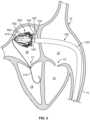
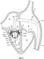
- an example transcatheter mitral valve delivery system 100can be navigated through a patient's vasculature to obtain access to the patient's heart 10.
- the transcatheter delivery system 100facilitates implantation of a prosthetic mitral valve in a beating heart 10 using a percutaneous, vessel cutdown, or minimally invasive technique (without open-chest surgery).
- the transcatheter delivery system 100is used in conjunction with one or more imaging modalities such as x-ray fluoroscopy, echocardiography, magnetic resonance imaging, computed tomography (CT), and the like.
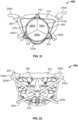
- the heart 10(depicted in cross-section from a posterior perspective) includes a right atrium 12, a right ventricle 14, a left atrium 16, and a left ventricle 18.
- a tricuspid valve 13separates the right atrium 12 from the right ventricle 14.
- a mitral valve 17separates the left atrium 16 from the left ventricle 18.
- An atrial septum 15separates the right atrium 12 from the left atrium 16.
- An inferior vena cava 11is confluent with the right atrium 12. It should be understood that this depiction of the heart 10 is somewhat stylized. The same is true for FIGS. 2-4 .
- FIGS. 1-4provide general depictions of the approach to the mitral valve 17 that is used in some implementations. But, the commissural cross-sectional views of FIG. 5 and thereafter more accurately depict the orientation of the prosthetic mitral valves in relation to the heart 10.
- the delivery system 100includes a guidewire 110, a primary deflectable catheter 120, and an anchor delivery sheath 130. Additional components of the delivery system 100 will be described further below.
- the anchor delivery sheath 130is slidably (and rotationally) disposed within a lumen of the primary deflectable catheter 120.
- the guidewire 110is slidably disposed within a lumen of the anchor delivery sheath 130.
- the anchor delivery sheath 130has been partially extended relative to the primary deflectable catheter 120, allowing a flared portion 132 to expand outward, as described further below.
- the guidewire 110is installed into the heart 10 prior to the other components of the delivery system 100.
- the guidewire 110has a diameter of about 0.035 inches (about 0.89 mm).
- the guidewire 110has a diameter in a range of about 0.032 inches to about 0.038 inches (about 0.8 mm to about 0.97 mm).
- the guidewire 110has a diameter smaller than 0.032 inches (about 0.80 mm) or larger than 0.038 inches (about 0.97 mm).
- the guidewire 110is made of materials such as, but not limited to, nitinol, stainless steel, high-tensile-strength stainless steel, and the like, and combinations thereof.
- the guidewire 110may include various tip designs (e.g., J-tip, straight tip, etc.), tapers, coatings, covers, radiopaque (RO) markers, and other features.
- the guidewire 110is percutaneously inserted into a femoral vein of the patient.
- the guidewire 110is routed to the inferior vena cava 11 and into the right atrium 12.
- the guidewire 110is routed into the left atrium 16.
- the guidewire 110is routed through the mitral valve 17 and into the left ventricle 18.
- the guidewire 110can be installed into the heart 10 along other anatomical pathways. The guidewire 110 thereafter serves as a rail over which other components of the delivery system 100 are passed.
- the primary deflectable catheter 120is installed by pushing it over the guidewire 110.
- a dilator tipis used in conjunction with the primary deflectable catheter 120 as the primary deflectable catheter 120 is advanced over the guidewire 110.
- a balloon cathetercould be used as the initial dilation means.
- the distal end portion of the primary deflectable catheter 120is steerable. Using steering, the distal end portion of the primary deflectable catheter 120 can be oriented as desired in order to navigate the patient's anatomy. For example, the primary deflectable catheter 120 can be angled within the right atrium 12 to navigate the primary deflectable catheter 120 from the inferior vena cava 11 to the atrial septum 15.
- the primary deflectable catheter 120has an outer diameter of about 28 Fr (about 9.3 mm). In some embodiments, the primary deflectable catheter 120 has an outer diameter in the range of about 26 Fr to about 34 Fr (about 8.7 mm to about 11.3 mm). In some embodiments, the primary deflectable catheter 120 has an outer diameter in the range of about 20 Fr to about 28 Fr (about 6.7 mm to about 9.3 mm).
- the primary deflectable catheter 120can comprise a tubular polymeric or metallic material.
- the primary deflectable catheter 120can be made from polymeric materials such as, but not limited to, polytetrafluoroethylene (PTFE), fluorinated ethylene propylene (FEP), HYTREL ® , nylon, PICOFLEX ® , PEBAX ® , TECOFLEX ® , and the like, and combinations thereof.
- the primary deflectable catheter 120can be made from metallic materials such as, but not limited to, nitinol, stainless steel, stainless steel alloys, titanium, titanium alloys, and the like, and combinations thereof.
- the primary deflectable catheter 120can be made from combinations of such polymeric and metallic materials (e.g., polymer layers with metal braid, coil reinforcement, stiffening members, and the like, and combinations thereof).
- the example delivery system 100also includes the anchor delivery sheath 130.
- the anchor delivery sheath 130is installed into a lumen of the primary deflectable catheter 120 (over the guidewire 110) and advanced through the primary deflectable catheter 120.
- the anchor delivery sheath 130is preloaded with a prosthetic valve anchor assembly and other components of the delivery system 100.
- the anchor delivery sheath 130can be made from the materials described above in reference to the primary deflectable catheter 120. In some embodiments, the anchor delivery sheath 130 has an outer diameter in the range of about 20 Fr to about 28 Fr (about 6.7 mm to about 9.3 mm). In some embodiments, the anchor delivery sheath 130 has an outer diameter in the range of about 14 Fr to about 24 Fr (about 4.7 mm to about 8.0 mm).
- the anchor delivery sheath 130includes a flared distal end portion 132. In some embodiments, no such flared distal end portion 132 is included.
- the flared distal end portion 132can collapse to a lower profile when constrained within the primary deflectable catheter 120. When the flared distal end portion 132 is expressed from the primary deflectable catheter 120, the flared distal end portion 132 can self-expand to the flared shape.
- the material of the flared distal end portion 132includes pleats or folds, may be a continuous flared end or may be separated into sections such as flower pedals, and may include one or more resilient elements that bias the flared distal end portion 132 to assume the flared configuration in the absence of restraining forces (such as from containment within the primary deflectable catheter 120).
- the flared distal end portion 132can be advantageous, for example, for recapturing the anchor assembly within the lumen of the anchor delivery sheath 130 after the anchor assembly has been expressed from the flared distal end portion 132.
- the maximum outer diameter of the flared distal end portion 132is in a range of about 30 Fr to about 34 Fr (about 10.0 mm to about 11.3 mm). In some embodiments, the maximum outer diameter of the flared distal end portion 132 is in a range of about 32 Fr to about 44 Fr (about 10.7 mm to about 14.7 mm). In some embodiments, the maximum outer diameter of the flared distal end portion 132 is in a range of about 24 Fr to about 30 Fr (about 8.0 mm to about 10.0 mm). In some embodiments, the maximum outer diameter of the flared distal end portion 132 is less than about 24 Fr (about 8.0 mm) or greater than about 44 Fr (about 14.7 mm).
- additional components of the example delivery system 100can include a proximal control sheath 140, a secondary deflectable catheter 150, and a distal pusher catheter 160.
- the proximal control sheath 140is slidably disposed within a lumen of the anchor delivery sheath 130.
- the secondary deflectable catheter 150is slidably disposed within a lumen of the proximal control sheath 140.
- the distal pusher catheter 160is slidably disposed within a lumen of the secondary deflectable catheter 150.
- These components of the delivery system 100can be manipulated by a clinician operator to control the position and orientation of an anchor assembly 200.
- the anchor assembly 200is slidably disposed over the guidewire 110.
- one or more of the proximal control sheath 140, the secondary deflectable catheter 150, the distal pusher catheter 160, and the anchor assembly 200have been loaded into the anchor delivery sheath 130 prior to the advancement of the anchor delivery sheath 130 into the primary deflectable catheter 120 as shown in FIG. 1 . That is, in some cases the proximal control sheath 140, the secondary deflectable catheter 150, the distal pusher catheter 160, and/or the anchor assembly 200 are already installed in the anchor delivery sheath 130 as the anchor delivery sheath 130 is distally advanced into the primary deflectable catheter 120 to attain the arrangement shown in FIG. 1 .
- one or more of the proximal control sheath 140, the secondary deflectable catheter 150, the distal pusher catheter 160, and the anchor assembly 200are distally advanced into the anchor delivery sheath 130 after the anchor delivery sheath 130 has been advanced into the primary deflectable catheter 120 to attain the arrangement shown in FIG. 1 .
- the distal pusher catheter 160is releasably coupled with a hub 210 of the anchor assembly 200.
- a proximal end of the anchor assembly 200is also releasably coupled to the proximal control sheath 140 by one or more control wires 142. While the depicted embodiment includes one control wire 142, in some embodiments two, three, four, five, or more than five control wires are included.
- the control wire 142is shown in an example engagement pattern with the anchor assembly 200.
- the control wire 142is threaded through a plurality of proximal portions of the anchor assembly 200.
- the control wire 142is configured in a lasso arrangement. Accordingly, a tensioning of the control wire 142 will cause at least the proximal end of the anchor assembly 200 to contract. Conversely, a removal of tension from the control wire 142 will allow the anchor assembly 200 to expand.
- the control wire 142is threaded through eyelets that are disposed on various positions on the anchor assembly 200.
- control wire 142is threaded through attachment features that are disposed on various positions on the covering or frame of the anchor assembly 200.
- the control wire 142can be tensioned or relaxed to arrive at a desired extent of expansion of the proximal end of the anchor assembly 200 (e.g., the atrial holding features 240a, 240b, 240c, and 240d, and/or the undulating supra-annular ring 250).
- Multiple control wires 142could also be used to achieve asymmetric, controlled expansion of the anchor assembly 300.
- the position of the anchor assembly 200can be controlled by manipulating the positions of the distal pusher catheter 160 and/or the proximal control sheath 140.
- the anchor assembly 200can be expressed out from the anchor delivery sheath 130 (as shown in FIG. 2 ) by moving the distal pusher catheter 160 and/or the proximal control sheath 140 distally in relation to the anchor delivery sheath 130.
- the expression of the anchor assembly 200is caused by proximally pulling back the anchor delivery sheath 130 while generally maintaining the positions of the distal pusher catheter 160 and/or the proximal control sheath 140.
- the expression of the anchor assembly 200is caused by a combination of proximally pulling back the anchor delivery sheath 130 while distally extending the positions of the distal pusher catheter 160 and/or the proximal control sheath 140.
- the anchor assembly 200expands from a low-profile delivery configuration to a partially expanded configuration (as shown in FIG. 2 ).
- the extent of expansion of the anchor assembly 200can be at least partially controlled by the relative positioning of the proximal control sheath 140 in relation to the distal pusher catheter 160. For instance, as the proximal control sheath 140 is moved proximally in relation to the distal pusher catheter 160, the anchor assembly 200 is axially elongated and radially contracted. Conversely, as the proximal control sheath 140 is moved distally in relation to the distal pusher catheter 160, the anchor assembly 200 is axially shortened and radially expanded.
- this control of the radial size of the anchor assembly 200is used by a clinician during the process of deploying the anchor assembly 200 within the native mitral valve 17, as described further below.
- the control wire 142can also be used to control some radial expansion of the anchor assembly 300 (without changing the relative distance of the proximal control sheath 140 in relation to the distal pusher catheter 160).
- the prosthetic mitral valves provided hereinare comprised of an anchor assembly 200 and a separable valve assembly (e.g., refer to FIGS. 14-20 ).
- the anchor assembly 200is deployed to an arrangement interfacing within the native mitral valve 17 prior to deployment of the valve assembly. Said differently, after implanting the anchor assembly 200 within the native mitral valve 17, the valve assembly can then be deployed within the anchor assembly 200 and within the native mitral valve 17 (as described further below). Therefore, it can be said that the prosthetic mitral valves provided herein are deployed using a staged implantation method. That is, the anchor assembly 200 is deployed in one stage, and the valve assembly is deployed in a subsequent stage.
- the deployment of the valve assemblytakes place right after the deployment of the anchor assembly 200 (e.g., during the same medical procedure). In some implementations, the deployment of the valve assembly takes place hours, days, weeks, or even months after the deployment of the anchor assembly 200 (e.g., during a subsequent medical procedure).
- the staged implantation method of the prosthetic mitral valves provided hereinis facilitated by the fact that when the anchor assembly 200 itself is implanted within the native mitral valve 17, the native mitral valve 17 continues to function essentially as before the implantation of the anchor assembly 200 without a significant impact on cardiovascular physiology. That is the case because, as described further below, the anchor assembly 200 interfaces and anchors within structural aspects of the native mitral valve 17 without substantially interfering with the leaflets or chordae tendineae of the native mitral valve 17.
- the distal end portion of the secondary deflectable catheter 150is located at least partially internally within the anchor assembly 200.
- the secondary deflectable catheter 150can be manipulated by a clinician operator to reversibly bend the distal end portion of the secondary deflectable catheter 150.
- other components of the delivery system 100may bend along with the secondary deflectable catheter 150.
- one or more of the distal pusher 160 and the proximal control sheath 140may bend in response to the bending of the deflectable catheter 150.
- the anchor assembly 200is coupled to the distal pusher 160 and the proximal control sheath 140, the anchor assembly 200 can, in turn, be rotated by bending the secondary deflectable catheter 150.
- the secondary deflectable catheter 150can be articulated (also referred to as steered, deflected, bent, curved, etc.) to pivot laterally (pan, rotate, etc.) the anchor assembly 200 while the anchor assembly 200 is within the left atrium 16.
- Such rotation of the anchor assembly 200is advantageous, for example, to orient the anchor assembly 200 in a desired relationship to the native mitral valve 17 in preparation for implanting the anchor assembly 200 within the native mitral valve 17.
- the lateral pivoting of the partially or fully expanded anchor assembly 200 within the atrium 16may be advantageous versus having to pivot laterally the anchor assembly 200 while it is still constrained within a delivery sheath, as the latter assembly is a relatively large and stiff catheter assembly.
- the clinician operatormay manipulate the radial size of the anchor frame 200 so that the anchor frame 200 can be passed through the native mitral valve 17 without damaging the native mitral valve 17.
- the cliniciancan move the proximal control sheath 140 proximally in relation to the distal pusher catheter 160 to radially contract the anchor assembly 200.
- the anchor assembly 200With the anchor assembly 200 radially contracted, the anchor frame 200 can be safely passed through the native mitral valve 17 without damaging the native mitral valve 17.
- the distal pusher catheter 160 and the proximal control sheath 140can be simultaneously advanced. Because the distal pusher catheter 160 is releasably coupled to the hub 210 of the anchor assembly 200, and because the proximal control sheath 140 is releasably coupled to the proximal end of the anchor assembly 200 via the one or more wires 142a and 142b, simultaneous advancement of the distal pusher catheter 160 and the proximal control sheath 140 results in advancement of the anchor assembly 200.
- the anchor assembly 200is advanced such that the distal end of anchor assembly 200 is within the left ventricle 18 while the proximal end of the anchor assembly 200 is within the left atrium 16. Hence, some portions of the anchor assembly 200 are on each side of the native mitral valve 17.
- the anchor assembly 200includes four anchor feet: a left anterior foot 220a, a left posterior foot 220b, a right posterior foot 220c, and a right anterior foot 220d. In some embodiments, fewer or more anchor feet may be included (e.g., two, three, five, six, or more than six). In some embodiments, the anchor feet 220a, 220b, 220c, and 220d are portions of the anchor assembly 200 that are configured for contact with a sub-annular gutter 19 of the native mitral valve 17, without penetrating tissue of the native mitral valve 17. Accordingly, the anchor feet 220a, 220b, 220c, and 220d have atraumatic surfaces that are generally comparable to feet. However, in some embodiments one or more of the anchor feet 220a, 220b, 220c, and 220d are configured to penetrate tissue and may have anchor features such as barbs, coils, hooks, and the like.
- the anchor feet 220a, 220b, 220c, and 220dare positioned below the sub-annular gutter 19.
- the radial size of the anchor assembly 200can be increased to align the anchor feet 220a, 220b, 220c, and 220d with the sub-annular gutter 19.
- the cliniciancan move the proximal control sheath 140 distally in relation to the distal pusher catheter 160 to radially expand the anchor assembly 200 to align the anchor feet 220a, 220b, 220c, and 220d with the sub-annular gutter 19.
- Such alignmentcan be performed in preparation for seating the anchor feet 220a, 220b, 220c, and 220d within the sub-annular gutter 19.
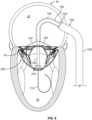
- a commissural cross-sectional view of the heart 10provides another perspective of the anchor assembly 200 in the same arrangement in relation to the native mitral valve 17 as shown in FIG. 4 .
- This commissural cross-sectional view of the heart 10is a cross-sectional view taken through the mitral valve 17 along a plane through the left atrium 16 and left ventricle 18 that is parallel to the line that intersects the two commissures of the mitral valve 17 (as described further in reference to FIG. 8 below).
- FIGS. 5-7 and 13-17the commissural cross-sectional view of the heart 10 will be used to describe the delivery system 100 and methods for deploying the prosthetic mitral valves provided herein.
- the view in FIGS. 5-7 and 13-17is slightly tilted so that better visualization of the anchor assembly 200 is provided.
- the anchor feet 220a, 220b, 220c, and 220dare positioned below the sub-annular gutter 19. In this position, the anchor feet 220a, 220b, 220c, and 220d are positioned under the systolic and diastolic excursions of the leaflets of the native mitral valve 17. In this orientation, the anchor feet 220a, 220b, 220c, and 220d can be aligned with the sub-annular gutter 19 in preparation for seating the anchor feet 220a, 220b, 220c, and 220d within the sub-annular gutter 19.
- the distal pusher 160 and the proximal control sheath 140can be simultaneously retracted in relation to the secondary deflectable catheter 150 and the primary deflectable catheter 120.
- the anchor feet 220a, 220b, 220c, and 220dbecome seated in the sub-annular gutter 19.
- the anchor feet 220a, 220b, 220c, and 220dare positioned under the systolic and diastolic excursions of the leaflets of the native mitral valve 17, and the other structures of the anchor assembly 200 do not inhibit the movements of the leaflets.
- the mitral valve 17can continue to function as it did before the placement of the anchor assembly 200.
- the manner in which the anchor assembly 200 interfaces with the native mitral valve 17does not result in deformation of the native mitral valve 17. Therefore, the native mitral valve 17 can continue to function as it did before the placement of the anchor assembly 200.
- components of the delivery system 100can be withdrawn from the anchor assembly 200.
- the control wire 142can be detached from the proximal end of the anchor assembly 200.
- the proximal control sheath 140can be withdrawn.
- the secondary deflectable catheter 150can also be withdrawn.
- the proximal control sheath 140, the secondary deflectable catheter 150, and the anchor delivery sheath 130can be completely withdrawn from the primary deflectable catheter 120.
- the distal pusher catheter 160is advantageously left attached to the hub 210 of the anchor assembly 200.
- the distal pusher catheter 160can be used as a rail on which a valve assembly is deployed into the interior of the anchor assembly 200.
- the anchor assembly 200is completely detached from the delivery system 100, and the delivery system 100 is removed from the patient. After a period of hours, days, weeks, or months, subsequent to the deployment of the anchor assembly 200, a valve assembly can be installed into the anchor assembly 200 to complete the installation of the prosthetic mitral valve.
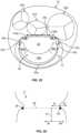
- the anatomy of the native mitral valve 17includes some consistent and predictable structural features across patients that can be utilized for engaging the anchor assembly 200 therewith.
- the native mitral valve 17includes the aforementioned sub-annular gutter 19.
- the native mitral valve 17includes a D-shaped annulus 28, an anterolateral commissure 30a, a posteromedial commissure 30b, a left fibrous trigone 134a, and a right fibrous trigone 134b.
- the native mitral valve 17includes an anterior leaflet 20 and a three-part posterior leaflet 22.
- the posterior leaflet 22includes a lateral scallop 24a, a middle scallop 24b, and a medial scallop 24c. The free edges of the posterior leaflet 22 and the anterior leaflet 20 meet along a coaptation line 32.
- the D-shaped annulus 28defines the structure from which the anterior leaflet 20 and posterior leaflet 22 extend and articulate.
- the left and right fibrous trigones 134a and 134bare located near the left and right ends of the anterior leaflet 20 and generally adjacent the lateral and medial scallops 24a and 24c of the posterior leaflet 22.
- the sub-annular gutter 19runs along the annulus 28 between the left and right fibrous trigones 134a and 134b along the posterior leaflet 22.
- the regions at or near the high collagen annular trigones 134a and 134bcan generally be relied upon to provide strong, stable anchoring locations.
- the muscle tissue in the regions at or near the trigones 134a and 134balso provides a good tissue ingrowth substrate for added stability and migration resistance of the anchor assembly 200. Therefore, the regions at or near the trigones 134a and 134b define a left anterior anchor zone 34a and a right anterior anchor zone 34b respectively.
- the left anterior anchor zone 34a and the right anterior anchor zone 34bprovide advantageous target locations for placement of the left anterior foot 220a and the right anterior foot 220d respectively.
- the depicted embodiment of the anchor assembly 200also includes the left posterior foot 220b and the right posterior foot 220c.
- the left posterior foot 220b and the right posterior foot 220ccan also be advantageously positioned in the sub-annular gutter 19 in order to provide balanced and atraumatic coupling of the anchor assembly 200 to the native mitral valve 17. Therefore, a left posterior anchor zone 34b and a right anterior anchor zone 34c are defined in the sub-annular gutter 19.
- the left posterior anchor zone 34b and the right anterior anchor zone 34ccan receive the left posterior foot 220b and the right posterior foot 220c respectively.
- the locations of the left posterior anchor zone 34b and the right anterior anchor zone 34cmay vary from the depicted locations while still remaining within the sub-annular gutter 19. It should be understood that the depicted anchor assembly 200 is merely one non-limiting example of the anchor assemblies provided within the scope of this disclosure.
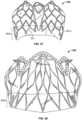
- the anchor assembly 200includes supra-annular structures and sub-annular structures.
- the sub-annular structures of the anchor assembly 200include the aforementioned anchor feet 220a, 220b, 220c, and 220d, and the hub 210.
- the hub 210functions as a connection structure for the delivery system 100 (e.g., refer to FIG. 2 ).
- the hub 210can function as a stabilizing structural component from which a left anterior sub-annular support arm 230a, a left posterior sub-annular support arm 230b, a right posterior sub-annular support arm 230c, and a right anterior sub-annular support arm 230d extend to the anchor feet 220a, 220b, 220c, and 220d respectively.
- the supra-annular structures of the anchor assembly 200include: a left anterior atrial holding feature 240a, a left posterior atrial holding feature 240b, a right posterior atrial holding feature 240c, and a right anterior atrial holding feature 240d; an anterior anchor arch 250a, a left anchor arch 250b, a posterior anchor arch 250c, and a right anchor arch 250d; and connection bridges 260.
- the anterior anchor arch 250a, left anchor arch 250b, posterior anchor arch 250c, and right anchor arch 250dare joined with each other to form an undulating supra-annular ring 250 that acts as a supra-annular structural element for the anchor assembly 200.
- the supra-annular ring 250also defines an opening to a space within the interior of the anchor assembly 200 that is configured to receive and engage with a valve assembly.
- the atrial holding features 240a, 240b, 240c, and 240dare configured to contact the shelf-like supra-annular tissue surface above the mitral valve annulus, and to thereby stabilize the anchor assembly 200 in supra-annular areas that are generally opposite of the anchor feet 220a, 220b, 220c, and 220d respectively.
- connection bridges 260provide enhanced stability and fatigue resistance from vertically oriented forces on a companion artificial valve assembly when the valve (not shown) is closed and blocking pressurized blood during systole.
- the anchor assembly 200can also include one or more holes 226 in frame portions adjacent the feet, which are additional control points for delivery and retrieval of the assembly, or could be used to secure a positional delivery frame.
- the supra-annular structures and sub-annular structures of the anchor assembly 200are interconnected by a lateral anterior inter-annular connection 270a, a lateral posterior inter-annular connection 270b, a medial posterior inter-annular connection 270c, and a medial anterior inter-annular connection 270d.
- the lateral anterior inter-annular connection 270aconnects the lateral anterior anchor foot 220a with the lateral anterior atrial holding feature 240a.
- the lateral anterior inter-annular connection 270aconnects the lateral anterior anchor foot 220a with the anterior anchor arch 250a and the left anchor arch 250b.
- each of the other inter-annular connections 270b, 270c, and 270dinterconnect portions of the supra-annular structures and sub-annular structures in manners analogous to that of the lateral anterior inter-annular connection 270a.
- the lateral anterior inter-annular connection 270bconnects the lateral anterior anchor foot 220b with the left anchor arch 250b and the posterior anchor arch 250c
- the lateral anterior inter-annular connection 270cconnects the lateral anterior anchor foot 220c with the posterior anchor arch 250c and the right anchor arch 250d
- the lateral anterior inter-annular connection 270dconnects the lateral anterior anchor foot 220d with the right anchor arch 250d and the anterior anchor arch 250a.
- the elongate members of the anchor assembly 200are formed from a single piece of precursor material (e.g., sheet or tube) that is cut, expanded, and connected to the hub 210.
- precursor materiale.g., sheet or tube
- some embodimentsare fabricated from a tube that is laser-cut (or machined, chemically etched, water-jet cut, etc.) and then expanded and heat-set into its final expanded size and shape.
- the anchor assembly 200is created compositely from multiple elongate members (e.g., wires or cut members) that are joined together with the hub 210 and each other to form the anchor assembly 200.
- the elongate members of the anchor assembly 200can be comprised of various materials and combinations of materials.
- nitinol (NiTi)is used as the material of the elongate members of the anchor assembly 200, but other materials such as stainless steel, L605 steel, polymers, MP35N steel, stainless steels, titanium, colbalt/chromium alloy, polymeric materials, Pyhnox, Elgiloy, or any other appropriate biocompatible material, and combinations thereof can be used.
- the super-elastic properties of NiTimake it a particularly good candidate material for the elongate members of the anchor assembly 200 because, for example, NiTi can be heat-set into a desired shape.
- NiTican be heat-set so that the anchor assembly 200 tends to self-expand into a desired shape when the anchor assembly 200 is unconstrained, such as when the anchor assembly 200 is deployed out from the anchor delivery sheath 130.
- a anchor assembly 200 made ofNiTi, for example,may have a spring nature that allows the anchor assembly 200 to be elastically collapsed or "crushed" to a low-profile delivery configuration and then to reconfigure to the expanded configuration as shown in FIG. 9 .
- the anchor assembly 200may be generally conformable, fatigue resistant, and elastic such that the anchor assembly 200 can conform to the topography of the surrounding tissue when the anchor assembly 200 is deployed in a native mitral valve of a patient.
- the diameter or width/thickness of one or more of the elongate members forming the anchor assembly 200may be within a range of about 0.008" to about 0.015" (about 0.20 mm to about 0.40 mm), or about 0.009" to about 0.030" (about 0.23 mm to about 0.76 mm), or about 0.01" to about 0.06" (about 0.25 mm to about 1.52 mm), or about 0.02" to about 0.10" (about 0.51 mm to about 2.54 mm), or about 0.06" to about 0.20" (about 1.52 mm to about 5.08 mm).
- the elongate members forming the anchor assembly 200may have smaller or larger diameters or widths/thicknesses.
- each of the elongate members forming the anchor assembly 200has essentially the same diameter or width/thickness. In some embodiments, one or more of the elongate members forming the anchor assembly 200 has a different diameter or width/thickness than one or more of the other elongate members of the anchor assembly 200. In some embodiments, one or more portions of one or more of the elongate members forming the anchor assembly 200 may be tapered, widened, narrowed, curved, radiused, wavy, spiraled, angled, and/or otherwise non-linear and/or not consistent along the entire length of the elongate members of the anchor assembly 200. Such features and techniques can also be incorporated with the valve assemblies of the prosthetic mitral valves provided herein.
- the elongate members forming the anchor assembly 200may vary in diameter, thickness and/or width so as to facilitate variations in the forces that are exerted by the anchor assembly 200 in specific regions thereof, to increase or decrease the flexibility of the anchor assembly 200 in certain regions, to enhance migration resistance, and/or to control the process of compression (crushability) in preparation for deployment and the process of expansion during deployment of the anchor assembly 200.
- one or more of the elongate members of the elongate members forming the anchor assembly 200may have a circular cross-section. In some embodiments, one or more of the elongate members forming the anchor assembly 200 may have a rectangular cross-sectional shape, or another cross-sectional shape that is not rectangular. Examples of cross-sectional shapes that the elongate members forming the anchor assembly 200 may have include circular, C-shaped, square, ovular, rectangular, elliptical, triangular, D-shaped, trapezoidal, including irregular cross-sectional shapes formed by a braided or stranded construct, and the like.
- one or more of the elongate members forming the anchor assembly 200may be essentially flat (i.e., such that the width to thickness ratio is about 2:1, about 3:1, about 4:1, about 5:1, or greater than about 5:1). In some examples, one or more of the elongate members forming the anchor assembly 200 may be formed using a center-less grind technique, such that the diameter of the elongate members varies along the length of the elongate members.
- the anchor assembly 200may include features that are directed to enhancing one or more desirable functional performance characteristics of the prosthetic mitral valve devices.
- some features of the anchor assembly 200may be directed to enhancing the conformability of the prosthetic mitral valve devices.
- Such featuresmay facilitate improved performance of the prosthetic mitral valve devices by allowing the devices to conform to irregular tissue topographies and/or dynamically variable tissue topographies, for example.
- Such conformability characteristicscan be advantageous for providing effective and durable performance of the prosthetic mitral valve devices.
- some portions of the anchor assembly 200are designed to be more conformable than other portions of the same anchor assembly 200. That is, the conformability of a single anchor assembly 200 can be designed to be different at various areas of the anchor assembly 200.
- the anchor assembly 200includes features for enhanced in vivo radiographic visibility.
- portions of the anchor assembly 200such as one or more of the anchor feet 220a, 220b, 220c, and 220d, may have one or more radiopaque markers attached thereto.
- some or all portions of the anchor assembly 200are coated (e.g., sputter coated) with a radiopaque coating.
- the anchor feet 220a, 220b, 220c, and 220dare sized and shaped to engage the sub-annular gutter 19 of the mitral valve 17.
- the anterior feet 220a and 220dare spaced apart from each other by a distance in a range of about 30 mm to about 45 mm, or about 20 mm to about 35 mm, or about 40 mm to about 55 mm.
- the posterior feet 220b and 220care spaced apart from each other by a distance in a range of about 20 mm to about 30 mm, or about 10 mm to about 25 mm, or about 25 mm to about 40 mm.
- the anchor feet 220a, 220b, 220c, and 220dhave a height ranging from about 8 mm to about 12 mm, or more than about 12 mm. In some embodiments, the anchor feet 220a, 220b, 220c, and 220d have a gutter engaging surface area (when fabric covered) ranging from about 6 mm 2 to about 24 mm 2 . In some embodiments, the anchor feet 220a, 220b, 220c, and 220d each have essentially the same gutter engaging surface area.
- one or more of the anchor feet 220a, 220b, 220c, and 220dhas a different gutter engaging surface area than one or more of the other anchor feet 220a, 220b, 220c, and 220d.
- the anchor feet 220a, 220b, 220c, and 220dcan have widths ranging within about 1.5 mm to about 4.0 mm or more, and lengths ranging within about 3 mm to about 6 mm or more.
- the anchor feet 220a, 220b, 220c, and 220dare sized and shaped so that the anchor assembly 200 does not significantly impair the natural function of mitral valve chordae tendineae, the native mitral valve leaflets, and papillary muscles even after the anchor assembly is anchored at the mitral valve site.
- the anchor assembly 200is designed to avoid interference with the functioning of the native mitral valve 17. Therefore, the anchor assembly 200 can be implanted within the native mitral valve 17 some time prior to the deployment therein of a replacement valve assembly, without degradation of valve 17 function during the period of time between the anchor implantation and the valve implantation (whether that time is on the order of minutes, or even several days or months).
- the inter-annular connections 270a, 270b, 270c, and 270dpass through the coaptation line 32 approximately. More particularly, the left anterior inter-annular connection 270a passes through the coaptation line 32 adjacent to the anterolateral commissure 30a.
- the right anterior inter-annular connection 270dpasses through the coaptation line 32 adjacent to the posteromedial commissure 30b.
- the left posterior inter-annular connection 270b and right posterior inter-annular connection 270cpass through the native mitral valve 17 in locations that are posteriorly biased from the natural coaptation line 32.
- the posterior leaflet 22will tend to compliantly wrap around the left posterior inter-annular connection 270b and right posterior inter-annular connection 270c to facilitate sealing of the mitral valve 17, with the anchor assembly 200 coupled thereto.
- the anchor assembly 200includes a covering material 270 disposed on one or more portions of the anchor assembly 200.
- the covering material 270can provide various benefits.
- the covering material 270can facilitate tissue ingrowth and/or endothelialization, thereby enhancing the migration resistance of the anchor assembly 200 and preventing thrombus formation on blood contact elements.
- the covering material 270can be used to facilitate coupling between the anchor assembly 200 and a valve assembly that is received therein.
- the cover material 270also prevents or minimizes abrasion and/or fretting between the anchor assembly 200 and valve assembly 300.
- the cover material 270also prevents valve outer tissue abrasion related wear.
- the covering material 270is disposed essentially on the entire anchor assembly 200. In some embodiments, the covering material 270 is disposed on one or more portions of the anchor assembly 200, while one or more other portions of the anchor assembly 200 do not have the covering material 270 disposed thereon. While the depicted embodiment includes the covering material 270, the covering material 270 is not required in all embodiments. In some embodiments, two or more portions of covering material 270, which can be separated and/or distinct from each other, can be disposed on the anchor assembly 200. That is, in some embodiments a particular type of covering material 270 is disposed on some areas of the anchor assembly 200 and a different type of covering material 270 is disposed on other areas of the anchor assembly 200.
- the covering material 270comprises a fluoropolymer, such as an expanded polytetrafluoroethylene (ePTFE) polymer.
- the covering material 270, or portions thereofcomprises a polyester, a silicone, a urethane, ELAST-EON TM (a silicone and urethane polymer), another biocompatible polymer, DACRON ® , polyethylene terephthalate (PET), copolymers, or combinations and subcombinations thereof.
- the covering material 270is manufactured using techniques such as, but not limited to, extrusion, expansion, heat-treating, sintering, knitting, braiding, weaving, chemically treating, and the like.
- the covering material 270comprises a biological tissue.
- the covering material 270can include natural tissues such as, but not limited to, bovine, porcine, ovine, or equine pericardium.
- the tissuesare chemically treated using glutaraldehyde, formaldehyde, or triglycidylamine (TGA) solutions, or other suitable tissue crosslinking agents.
- the covering material 270is disposed on the interior and the exterior of the anchor assembly 200. In some embodiments, the covering material 270 is disposed on the just the exterior of the anchor assembly 200. In some embodiments, the covering material 270 is disposed on the just the interior of the anchor assembly 200. In some embodiments, some portions of the anchor assembly 200 are covered by the covering material 270 in a different manner than other portions of the anchor assembly 200.
- the covering material 270is attached to at least some portions of the anchor assembly 200 using an adhesive.
- FEPfluorinated ethylene propylene
- an FEP coatingcan be applied to some or all portions of the anchor assembly 200, and the FEP can act as a bonding agent to adhere the covering material 270 to the anchor assembly 200.
- wrapping, stitching, lashing, banding, and/or clips, and the likecan be used to attach the covering material 270 to the anchor assembly 200.
- a combination of techniquesare used to attach the covering material 270 to the anchor assembly 200.
- the covering material 270has a microporous structure that provides a tissue ingrowth scaffold for durable sealing and/or supplemental anchoring strength of the anchor assembly 200.
- the covering material 270is made of a membranous material that inhibits or reduces the passage of blood through the covering material 270.
- the covering material 270, or portions thereofhas a material composition and/or configuration that inhibits or prevents tissue ingrowth and/or endothelialization to the covering material 270.
- the covering material 270can be modified by one or more chemical or physical processes that enhance certain physical properties of the covering material 270. For example, a hydrophilic coating may be applied to the covering material 270 to improve the wettability and echo translucency of the covering material 270.
- the covering material 270may be modified with chemical moieties that promote or inhibit one or more of endothelial cell attachment, endothelial cell migration, endothelial cell proliferation, and resistance to thrombosis.
- the covering material 270may be modified with covalently attached heparin or impregnated with one or more drug substances that are released in situ.
- covering material 270is pre-perforated to modulate fluid flow through the covering material 270 and/or to affect the propensity for tissue ingrowth to the covering material 270.
- the covering material 270is treated to make the covering material 270 stiffer or to add surface texture.
- the covering material 270is treated with FEP powder to provide a stiffened covering material 270 or roughened surface on the covering material 270.
- selected portions of the covering material 270are so treated, while other portions of the covering material 270 are not so treated.
- Other covering material 270 material treatment techniquescan also be employed to provide beneficial mechanical properties and tissue response interactions.
- portions of the covering material 270have one or more radiopaque markers attached thereto to enhance in vivo radiographic visualization.
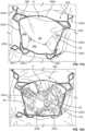
- FIGS. 11A and 12Aare photographs that correspond to FIGS. 11A and 12A respectively.
- the mitral valve 17is shown in a closed state.
- the mitral valve 17is shown in an open state. These illustrations are from the perspective of the left atrium looking towards the mitral valve 17. For instance, in FIG. 12A chordae tendineae 40 are visible through the open leaflets of the mitral valve 17.
- FIG. 11Aillustrates the supra-annular structures and sub-annular structures of the anchor assembly 200 in their relationships with the native mitral valve 17.
- the closed state of the native mitral valve 17 in FIG. 11Aallows visibility of the supra-annular structures such as the left anterior atrial holding feature 240a, the left posterior atrial holding feature 240b, the right posterior atrial holding feature 240c, and the right anterior atrial holding feature 240d.
- the anterior anchor arch 250a, the left anchor arch 250b, the posterior anchor arch 250c, the right anchor arch 250d, and the connection bridges 260are visible.
- the sub-annular structuresare not visible in FIG. 11A because such structures are obstructed from view by the anterior leaflet 20 and the three-part posterior leaflet 24a, 24b, and 24c.
- FIG. 12Acertain sub-annular structures of the anchor assembly 200 are visible because the native mitral valve 17 is open.
- sub-annular support arms 230a, 230b, 230c, and 230d and hub 210are in view through the open mitral valve 17.
- the anchor feet 220a, 220b, 220c, and 220dremain out of view because of their location within the sub-annular gutter of the mitral valve 17.
- a valve delivery sheath 170 of the delivery system 100can be used to deploy a valve assembly within the anchor assembly 200.
- the distal pusher catheter 160can be used to guide the valve assembly into the interior of the anchor assembly 200.
- the valve delivery sheath 170is installed into a lumen of the primary deflectable catheter 120 (over the distal pusher catheter 160) and advanced through the primary deflectable catheter 120.
- the valve delivery sheath 170is preloaded with a prosthetic valve assembly and other components of the delivery system 100.
- the primary deflectable catheter 120may be the same catheter that was used to deliver the anchor assembly 200, or it may be a different catheter (but still referred to here as the primary deflectable catheter 120 for simplicity sake).
- the valve delivery sheath 170can be made from the materials described above in reference to the primary deflectable catheter 120. In some embodiments, the valve delivery sheath 170 has an outer diameter in the range of about 20 Fr to about 28 Fr (about 6.7 mm to about 9.3 mm). In some embodiments, the valve delivery sheath 170 has an outer diameter in the range of about 14 Fr to about 24 Fr (about 4.7 mm to about 8.0 mm).
- the valve delivery sheath 170includes a flared distal end portion 172. In some embodiments, no such flared distal end portion 172 is included.
- the flared distal end portion 172can collapse to a lower profile when constrained within the primary deflectable catheter 120. When the flared distal end portion 172 is expressed from the primary deflectable catheter 120, the flared distal end portion 172 can self-expand to the flared shape.
- the material of the flared distal end portion 172includes pleats or folds, may be a continuous flared end or may be separated into sections such as flower pedals, and may include one or more resilient elements that bias the flared distal end portion 172 to assume the flared configuration in the absence of restraining forces (such as from containment within the primary deflectable catheter 120).
- the flared distal end portion 172can be advantageous, for example, for recapturing the valve assembly within the lumen of the valve delivery sheath 170 after the valve assembly has been expressed from the flared distal end portion 172.
- the maximum outer diameter of the flared distal end portion 172is in a range of about 30 Fr to about 34 Fr (about 10.0 mm to about 11.3 mm). In some embodiments, the maximum outer diameter of the flared distal end portion 172 is in a range of about 32 Fr to about 44 Fr (about 10.7 mm to about 14.7 mm). In some embodiments, the maximum outer diameter of the flared distal end portion 172 is in a range of about 24 Fr to about 30 Fr (about 8.0 mm to about 10.0 mm). In some embodiments, the maximum outer diameter of the flared distal end portion 172 is less than about 24 Fr (about 8.0 mm) or greater than about 44 Fr (about 14.7 mm).
- valve delivery sheath 170can be withdrawn into the primary deflectable catheter 120 while a valve delivery catheter 180 is held substantially stationary to express a valve assembly 300 from a lumen of the valve delivery sheath 170.
- the valve delivery sheath 170 and the valve delivery catheter 180are additional components in some embodiments of the example delivery system 100.
- the valve assembly 300can be releasably coupled to the valve delivery catheter 180 and retained in a low-profile configuration. In some embodiments, both the distal and proximal ends of the valve assembly 300 are releasably coupled to the valve delivery catheter 180. In some embodiments, just one of the distal end or the proximal end of the valve assembly 300 is releasably coupled to the valve delivery catheter 180. In particular embodiments, one or more control wires may be included to releasably couple one or more portions of the valve assembly 300 to the valve delivery catheter 180.
- the valve assembly 300is releasably coupled to the valve delivery catheter 180 via a proximal control wire 342a and a mid-body control wire 342b.
- the control wires 342a and 342bare threaded through one or more lumens within the valve delivery catheter 180.
- the control wires 342a and 342bexit the valve delivery catheter 180 and pass through eyelets on the proximal end and mid-body portions of the valve assembly 300 respectively.
- the control wires 342a and 342bare then threaded back into the valve delivery catheter 180.
- a clinician operatorcan control the valve assembly 300.
- the expansion and contraction of the valve assembly 300can be controlled, and the detachment of the valve assembly 300 from the valve delivery catheter can be controlled, by manipulating the tension and position of the control wires 342a and 342b within the delivery catheter 180.
- a lumen of the valve delivery catheter 180can slidably surround the distal pusher catheter 160. Therefore, advancement of the valve delivery catheter 180 results in advancement of the valve assembly 300 over the distal pusher catheter 160 towards the anchor assembly 200.
- the delivery system 100can be manipulated by a clinician operator to perform a lateral pivot (panning, rotation, etc.) of the valve assembly 300 within the left atrium 16.
- the rotation of the valve assembly 300changes the alignment of the valve assembly 300 from being generally axial with the distal end portion of the primary deflectable catheter 120 to being generally axial with the anchor assembly 200 (in preparation for installation of the valve assembly 300 into the interior of the anchor assembly 200).
- the aforementioned rotation of the valve assembly 300can be performed as follows. As shown in FIG. 15 , because of the influence from the primary deflectable catheter 120 on the valve delivery catheter 180, the axis of the valve assembly 300 is initially in general alignment with the axis of the distal end portion of the primary deflectable catheter 120. From this arrangement, a simultaneous counter movement between the distal pusher catheter 160 and the valve delivery catheter 180 can be performed by the clinician to rotate the valve assembly 300. That is, as the distal pusher catheter 160 is pulled proximally, the valve delivery catheter 180 is pushed distally. As a result of that counter movement, the valve assembly 300 rotates in a relatively tight radius, as required by the confines of the left atrium 16. Thereafter, the valve delivery catheter 180 can be advanced further so that the valve assembly 300 is coaxially positioned within the interior of the anchor assembly 200 as shown in FIG. 16 .
- valve assembly 300 and the anchor assembly 200become aligned with each other coaxially, linearly (along their axes), and rotationally prior to or during the expansion of the valve assembly 300, resulting in engagement between the valve assembly 300 and the anchor assembly 200. Thereafter, the delivery system 100 can be withdrawn from the heart 10 and the prosthetic mitral valve can perform its function.
- Coaxial alignment between the valve assembly 300 and the anchor assembly 200is achieved by virtue of the valve delivery catheter 180 being slidably disposed over the distal pusher catheter 160.
- Linear alignment between the valve assembly 300 and the anchor assembly 200can be achieved by the interaction of a distal end feature 182 of the valve delivery catheter 180 and the hub 210 of the anchor assembly 200.
- an abutting of the distal end feature 182 and the hub 210can result in proper linear alignment between the valve assembly 300 and the anchor assembly 200.
- Relative rotational alignment between the valve assembly 300 and the anchor assembly 200can be achieved in various manners.
- the valve delivery catheter 180is mechanically keyed to the distal pusher catheter 160 to slidably fix a desired rotational alignment between the valve assembly 300 and the anchor assembly 200.
- other types of mechanical featurese.g., pins/holes, protrusions/receptacles, etc.
- radiopaque markerscan be included on the valve assembly 300 and on the anchor assembly 200 in locations and/or patterns that are indicative of the relative rotational orientation (about their axes) of the valve assembly 300 and the anchor assembly 200.
- the valve delivery catheter 180can be rotated about its axis until the markers are in proper position relative to the anchor assembly 200, prior to final expansion of valve assembly 300. Fluoroscopy can be used to attain a desired relative orientation of the radiopaque markers, and of the valve assembly 300 and the anchor assembly 200 correspondingly.
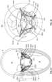
- valve assembly 300is shown without any covering or valve/occluder leaflets.
- a valve assembly frame 301 of the valve assembly 300is shown.
- FIG. 18shows an anterior side view of the valve assembly frame 301
- FIG. 19shows a bottom view of the valve assembly frame 301.
- the valve assembly 300can be constructed using any of the various materials and manufacturing techniques described above in reference to the anchor frame 200 (e.g., refer to FIG. 9 ). It should be understood that the depicted valve assembly 300 is merely one non-limiting example of the valve assemblies provided within the scope of this disclosure.
- the valve assembly 300includes a proximal end portion 302 and a distal end portion 304.
- the valve assemblyincludes a flared external skirt portion 303 and defines an interior orifice portion 305.
- the proximal end portion 302is located supra-annular (in the left atrium) and the distal end portion 304 is located sub-annular (in the left ventricle).
- the proximal end portion 302defines the generally circular entrance orifice of the valve assembly 300, as described further below.
- the valve assembly 300generally flares outward along a distal direction.
- the distal end portion 304is flared outward in comparison to the proximal end portion 302.
- the proximal end portion 302defines a smaller outer profile in comparison to the distal end portion 304.
- some regions of the distal end portion 304bow inwardly.
- a posteromedial commissural corner 330a and anterolateral commissural corner 330b of the valve assembly 300may bow inwardly.
- the outward flare of the distal end portion 304 in comparison to the proximal end portion 302is merely one example configuration for a profile of the valve assembly 300.
- a shoulder(a portion of the valve assembly 300 having the largest outer periphery) is located proximal of the middle of the valve assembly 300.
- the valve assembly 300also includes an anterior side 306 between the posteromedial commissural corner 330a and anterolateral commissural corner 330b.
- the anterior side 306faces the anterior leaflet of the native mitral valve.
- the anterior side 306 of the distal end portion 304defines a generally flat surface, whereas the other sides of the distal end portion 304 are rounded.
- the periphery of the distal end portion 304is generally D-shaped.
- the D-shaped periphery of the distal end portion 304provides the valve assembly 300 with an advantageous outer profile for interfacing and sealing with the native mitral valve.
- sealingis attained by coaptation between the D-shaped periphery of the distal end portion 304 and the leaflets of the native mitral valve, and, in some embodiments, between the D-shaped periphery in the region of the skirt 303 with the native valve annulus.
- the proximal end portion 302 of the valve assembly 300includes three atrial leaflet arches 310a, 310b, and 310c that together define an undulating ring at the proximal end portion 302.
- Each of the leaflet arches 310a, 310b, and 310cincludes an apex having an attachment hole 312a, 312b, and 312c respectively.
- the attachment holes 312a, 312b, and 312care used for coupling the proximal end of the valve assembly 300 to a delivery catheter (e.g., valve delivery catheter 180 of FIGS. 14-16 ).
- the valve assembly 300also includes three commissural posts 320a, 320b, and 320c that each extend distally from the intersections of the three leaflet arches 310a, 310b, and 310c.
- the commissural posts 320a, 320b, and 320care disposed at about 120° apart from each other.
- the commissural posts 320a, 320b, and 320ceach have a series of holes that can be used for attachment of leaflets, such as by suturing.
- the three leaflet arches 310a, 310b, and 3 10c and the three commissural posts 320a, 320b, and 320care areas on the valve assembly 300 to which three prosthetic valve leaflets become attached to comprise a tri-leaflet occluder (e.g., refer to FIGS. 22-25 ).
- the three leaflet arches 310a, 310b, and 310c and the commissural posts 320a, 320b, and 320cdefine a generally cylindrical frame for the tri-leaflet occluder construct.
- the valve assembly 300provides a proven and advantageous frame configuration for the tri-leaflet occluder.
- the tri-leaflet occluderprovides open flow during diastole and occlusion of flow during systole.
- an exploded depiction of an example prosthetic mitral valve 400includes an anchor assembly 200 and a valve assembly 300. This figures provides a posterior side view of the anchor assembly 200 and the valve assembly 300.
- the valve assembly 300includes a covering 340.
- the covering 340can be made of any of the materials and constructed using any of the techniques described above in reference to covering 270. Additionally, in some embodiments the covering 340 can comprise natural tissues such as, but not limited to, bovine, porcine, ovine, or equine pericardium. In some such embodiments, the tissues are chemically cross-linked using glutaraldehyde, formaldehyde, or triglycidyl amine solution, or other suitable crosslinking agents.
- valve assembly 300When the valve assembly 300 and the anchor assembly 200 are coupled together, the valve assembly 300 is geometrically interlocked within the interior of the anchor assembly 200 (e.g., in some embodiments by virtue of the tapered shape of the valve assembly 300 within the supra-annular ring and interior space of the anchor assembly 200). In particular, in some embodiments the valve assembly 300 is contained within the interior space between the supra-annular ring 250 and the sub-annular support arms 230a, 230b, 230c, and 230d.
- the interlocked arrangement between the valve assembly 300 and the anchor assembly 200is accomplished by positioning a valve assembly 300 in a low-profile configuration within the interior of the anchor assembly 200 and then allowing expansion of the valve assembly 300 within the interior of the anchor assembly 200 (e.g., refer to FIGS. 16 and 17 ).
- a deployed configuration of the example prosthetic mitral valve 400includes the valve assembly 300 engaged within the anchor assembly 200.
- FIG. 21shows a top (atrial) view of the prosthetic mitral valve 400
- FIG. 22shows a bottom (ventricle) view of the prosthetic mitral valve 400.
- valve assembly 300includes three leaflets 350a, 350b, and 350c that perform the occluding function of the prosthetic mitral valve 400.
- the cusps of the three leaflets 350a, 350b, and 350care fixed to the three atrial leaflet arches 310a, 310b, and 310c, and to the three commissural posts 320a, 320b, and 320c (refer to FIGS. 18 and 19 ).
- the free edges of the three leaflets 350a, 350b, and 350ccan seal by coaptation with each other during systole and open during diastole.
- the three leaflets 350a, 350b, and 350ccan be comprised of natural or synthetic materials.
- the three leaflets 350a, 350b, and 350ccan be comprised of any of the materials described above in reference to the covering 340, including the natural tissues such as, but not limited to, bovine, porcine, ovine, or equine pericardium.
- the tissuesare chemically cross-linked using glutaraldehyde, formaldehyde, or triglycidyl amine solution, or other suitable crosslinking agents.
- the leaflets 350a, 350b, and 350chave a thickness in a range of about 0.005" to about 0.020" (about 0.13 mm to about 0.51 mm), or about 0.008" to about 0.012" (about 0.20 mm to about 0.31 mm). In some embodiments, the leaflets 350a, 350b, and 350c have a thickness that is less than about 0.005" (about 0.13 mm) or greater than about 0.020" (about 0.51 mm).
- the occluding function of the prosthetic mitral valve 400can be performed using configurations other than a tri-leaflet occluder.
- bi-leaflet, quad-leaflet, or mechanical valve constructscan be used in some embodiments.
- the prosthetic mitral valve 400is shown implanted within a native mitral valve 17.
- the prosthetic mitral valve 400is shown in a closed state (occluded).
- the prosthetic mitral valve 400is shown in an open state.
- These illustrationsare from the perspective of the left atrium looking towards the mitral valve 17.
- the hub 210 and the sub-annular support arms 230a, 230b, 230c, and 230d of the anchor assembly 200is visible through the open leaflets 350a, 350b, and 350c of the prosthetic mitral valve 400
- the hub 210 and the sub-annular support arms 230a, 230b, 230c, and 230dare not visible because the closed leaflets 350a, 350b, and 350c block the hub 210 from view.
- FIGS. 25-33describe additional aspects pertaining to sealing between native mitral valve structures and the implantable prosthetic mitral valves described herein.
- ventricle-to-atrium sealingis relevant in order to effectively treat MR via implantation of a prosthetic mitral valve.
- atrium-to-ventricle sealing between native mitral valve structures and the prosthetic mitral valves described hereinis relevant for preventing or reducing paravalvular leakage, and for good healing and chronic stability.
- the prosthetic mitral valves described hereinare designed to have various features that provide for effective sealing with the native mitral valve structures.
- One feature that enhances the sealing of the prosthetic mitral valves provided hereinpertains to the shape of the prosthetic valve framework in relation to the shape of the native mitral valve.
- the annulus of a native mitral valveis generally D-shaped (e.g., refer to FIG. 8 ).
- the distal end portions of the prosthetic mitral valves described hereinare D-shaped (e.g., refer to FIG. 19 ).
- the portion of the prosthetic valve that is designed to interface with the native valve annulushas a D-shaped profile that is similar to the shape of the annulus. This similarity of shapes can provide particular sealing efficacy in the areas of the lateral scallop 24a and the medial scallop 24c of the posterior leaflets 22 (refer to FIG. 8 ).
- a selected prosthetic valvewill intentionally have an outer profile (when unconstrained) that is equal to or slightly larger than the size of the annulus of the native mitral valve. That is, in the area on the valve surface that is intended to be adjacent to the native valve annulus, the size of the valve may result in a line-to-line fit or a slight interference fit with the native valve annulus.
- the atrium-to-ventricle sealing during diastoleis provided by the line-to-line fit or slight interference fit between the valve and the native valve annulus.
- Another feature that enhances the sealing of the prosthetic mitral valves provided hereinpertains to the relative geometric orientation of sealing surfaces on the prosthetic valve in relation to the annulus of the native mitral valve. While in some implementations, some sealing is provided by the mechanical fit between the outer profile of the valve and the receiving structure of the native mitral valve, in some implementations substantial sealing is provided by coaptation between the native leaflets and sealing surfaces on the perimeter of the prosthetic valve (to thereby create a contact seal during diastole and a left ventricle pressurized seal during systole). This type of sealing may be referred to herein as a leaflet to valve body seal.
- the prosthetic mitral valves provided hereinhave sealing surfaces that are geometrically oriented in relation to the native valve annulus so that a leaflet to valve body seal is provided. While the leaflet to valve body seal is not entirely a mechanically compressive type of seal or an attachment onto the native tissue (active fixation) type of seal, in some embodiments such mechanical or attachment type of seals may alternatively or additionally be incorporated.
- an effective leaflet to valve body sealmay necessitate some native leaflet movement to the sealing surface of the valve body.
- a valve body shapethat mimics the shape of the native mitral valve is advantageous.
- the outer periphery of the valve assemblies provided hereinhave a D-shaped periphery that generally correlates with the D-shaped annulus of native mitral valves. Accordingly, the movement distance of the native valve leaflets to the sealing surface of the valve body can be minimized (or essentially eliminated in some implementations), and sealing can thereby be enhanced.
- an effective leaflet to valve body sealexhibits contiguous coaptation between the native leaflets and prosthetic valve body around the entire periphery of the prosthetic valve body.
- the profiles of the prosthetic mitral valves provided hereinare designed to interface with the native leaflets so as to provide contiguous coaptation around the entire periphery of the prosthetic valve.
- the profile of some regions of the prosthetic mitral valvesare different than the profile of other regions of the same valve (e.g., in correspondence with differing anatomical features in various portions of the native mitral valve).
- a lateral cross-sectional atrial view of a heart 10shows the mitral valve 17, aortic valve 510, tricuspid valve, 520 and pulmonary valve 530.
- the mitral valve 17includes the anterior leaflet 20, the posterior leaflet 22 (including the medial scallop 24a, the middle scallop 24b, and the lateral scallop 24c), the left fibrous trigone 134a, and the right fibrous trigone 134b.
- the differing anatomical features of various portions of the native mitral valve 17make it advantageous to consider the mitral valve 17 as having three distinct sealing regions that together comprise the entirety of the mitral valve 17.
- the three distinct sealing regionsare: an anterior region 25a, a posterior region 25b, and two commissural regions 25c.
- the anterior region 25aextends generally linearly between the left and right trigones 134a and 134b.
- the posterior region 25bcomprises the middle scallop 24b and posterior portions of the lateral scallop 24a and medial scallop 24c.
- the commissural regions 25cextend between the anterior region 25a and the posterior region 25b.
- the commissural regions 25cgenerally encompass the commissures 30a and 30b, and anterior portions of the lateral scallop 24a and medial scallop 24c. These three sealing regions 25a, 25b, and 25c will be referenced again in regard to FIGS. 28-33 .
- a schematic diagram of a cross-section of a native mitral 17 valveindicates the location of the mitral valve annulus 28.
- Three geometric variables (S, W, and H) that can be used to quantify a relative geometric orientation of sealing surfaces on the prosthetic valve in relation to the annulus 28 of the native mitral valve 17are also indicated.
- the term "sealing surfaces”is defined as surface areas on the prosthetic valve that are intended to make sealing contact with structures of the native mitral valve 17 (especially the leaflets of the native mitral valve 17). Hence, the sealing surfaces are the areas on the prosthetic valve that are used to facilitate the leaflet to valve body seal.
- the geometric variable Squantifies the radial distance from the annulus 28 to the adjacent prosthetic valve framework surface.
- a negative S-valueindicates that the annulus 28 and the adjacent prosthetic valve surface are spaced apart from each other.
- an S-value of negative 2 mmindicates that there is a 2 mm space between the annulus 28 and the adjacent prosthetic valve surface.
- SWhen S equals zero, it indicates that the annulus 28 and the adjacent prosthetic valve surface are in contact with each other in a line-to-line fit relationship.
- Sis a positive number, it indicates that the annulus 28 and the adjacent prosthetic valve surface are in an interference fit relationship. In other words, when S is a positive number some compressive force is being applied to the annulus 28 by the adjacent prosthetic valve surface.
- the geometric variable Hquantifies the distance from the superior limit (upper edge) to the inferior limit (lower edge) of the sealing surface on the prosthetic valve.
- H-valuesare measured downward (in reference to the illustration). For example, an H-value of 10 mm indicates that, for a particular sealing region, the sealing surface on the prosthetic valve ends 10 mm below the superior limit of the sealing surface.
- an H-value of 7 mmindicates that the inferior limit of the sealing surface is 7 mm below the annulus 28.
- the superior limit of the sealing surface on the prosthetic valveis either at, slightly above, or slightly below the annulus 28 (e.g., about 2 mm above or about 2mm below the annulus 28 in some embodiments).
- the geometric variable Wquantifies the radial distance from the superior limit of the sealing surface to the inferior limit of the sealing surface on the prosthetic valve.
- a negative W-valueindicates that the inferior limit of the sealing surface is positioned radially inward in comparison to the superior limit of the sealing surface (e.g., at least a portion of the sealing surface is flared or bowed inward at the distal end).
- a positive W-valueindicates that the inferior limit of the sealing surface is positioned radially outward in comparison to superior limit of the sealing surface (e.g., at least a portion of the sealing surface is flared or bowed outward at the distal end).
- a W-value of zeroindicates that the inferior limit of the sealing surface is positioned at the same radial position as the superior limit of the sealing surface.
- an anterior side view of a valve assembly 300includes an anterior sealing surface 360a in accordance with some embodiments.
- the anterior sealing surface 360aspans the lower portion of the anterior side of valve assembly 300.
- the anterior sealing surface 360acomprises the surface area on the anterior side of the prosthetic valve assembly 300 that is intended to make sealing contact with structures of the native mitral valve.
- the anterior sealing surface 360aconsists of structural support from the valve frame 301 as well as a tissue surface 361a.
- the anterior tissue surface 361aprovides sealing interface height (H) but its flexible nature reduces the amount of LVOT obstruction, as will be described later.
- Hsealing interface height
- at least a portion of the anterior sealing surface 360ais intended to make sealing contact with the anterior leaflet of the native mitral valve.
- a posterior side view of a valve assembly 300includes a posterior sealing surface 360b in accordance with some embodiments.
- the posterior sealing surface 360bspans the lower portion of the posterior side of valve assembly 300.
- the posterior sealing surface 360bcomprises the surface area on the posterior side of the prosthetic valve assembly 300 that is intended to make sealing contact with structures of the native mitral valve.
- at least a portion of the posterior sealing surface 360bis intended to make sealing contact with the posterior leaflet of the native mitral valve.
- a commissural (lateral) side view of a valve assembly 300includes a commissural sealing surface 360c in accordance with some embodiments. This view is slightly biased to the anterior side of the valve assembly 300.
- the commissural sealing surface 360cspans the lower portion of the commissural side of valve assembly 300.
- the commissural sealing surface 360ccomprises the surface area on the lateral side of the prosthetic valve assembly 300 that is intended to make sealing contact with structures of the native mitral valve.
- at least a portion of the commissural sealing surface 360cis intended to make sealing contact with the medial scallop or the lateral scallop of the posterior leaflet of the native mitral valve, and with the leaflet tissue in the commissural regions of the native mitral valve.
- the geometric relationship between a native mitral valve annulus and an anterior sealing surface of a prosthetic mitral valve in accordance with some embodimentscan be represented by the S, H, and W values as described above in reference to FIG. 26 .
- the S-value of the anterior sealing surface of the prosthetic mitral valveis in a range from about zero millimeters to about positive 2 millimeters.
- the S-value of the anterior sealing surface in relation to the native mitral valve annulusis in a range from about line-to-line contact to about 2 millimeters interference.
- an interference fitdoes not necessarily mean that the native valve annulus is stretched or deformed as a result of the interference.
- the prosthetic valve assemblywill be inhibited by the annulus from enlarging to its unconstrained fully expanded size.
- the S-valueis in a range of about zero millimeters to about positive 2 millimeters, in some embodiments the S-value is in a range of about negative 2 millimeters to about positive 1 millimeter, or about negative 1 millimeter to about positive 3 millimeters, or about zero millimeters to about positive 4 millimeters. In some embodiments, the S-value can be more negative than about negative 2 millimeters or more positive than about positive 4 millimeters.
- the H-value of the anterior sealing surface of the prosthetic mitral valveis about 14 millimeters. In other words, in some embodiments the distance from the superior edge of the anterior sealing surface to the inferior edge of the anterior sealing surface is about 14 millimeters. More specifically, the H-value of the anterior sealing surface can be divided into two portions: (1) a superior portion, H LVOT and (2) an inferior portion, H TISSUE .
- the H LVOT -valuegenerally corresponds to the distance from the superior edge of the anterior sealing surface to the inferior end of the valve frame 301 at various places along the anterior sealing surface 360a (refer to FIG. 27 ).
- the H TISSUE -valuecorresponds to the distance from the inferior end of the valve frame 301 at various places along the anterior sealing surface 360a to the inferior end of the anterior tissue surface 361a at those places. While in the depicted embodiment, the H LVOT -value and the H TISSUE -value are equal to each other, in some embodiments the ratio between the H LVOT -value and the H TISSUE -value is about 3:1, about 2:1, about 1.5:1, about 1:1.5, about 1:2, or about 3:1.
- the total H-valueis about 14 millimeters
- the H-valueis in a range of about 8 millimeters to about 10 millimeters, or about 10 millimeters to about 12 millimeters, or about 12 millimeters to about 14 millimeters, or about 14 millimeters to about 16 millimeters, or about 13 millimeters to about 15 millimeters.
- the H-valuecan be less than about 8 millimeters or more than about 16 millimeters.
- the W-value of the anterior sealing surface of the prosthetic mitral valveis about negative 2 millimeters.
- the radial distance from the superior edge of the anterior sealing surface to the inferior edge of the anterior sealing surface on the prosthetic valveis about negative 2 millimeters.
- a W-value of negative 2 millimetersindicates that the lower edge of the anterior sealing surface is positioned radially inward in comparison to the superior edge of the anterior sealing surface by about 2 millimeters. This also indicates that the sub-annular anterior valve assembly is flared or bowed inward, such as indicated by valve body profile line 362a.
- the W-valueis about negative 2 millimeters
- the W-valueis in a range of about negative 6 millimeters to about negative 4 millimeters, or about negative 4 millimeters to about negative 2 millimeters, or about negative 2 millimeters to about zero millimeters, or about zero millimeters to about positive 2 millimeters, or about negative 3 millimeters to about negative 1 millimeter.
- the W-valuecan be more negative than about negative 6 millimeters or more positive than about positive 2 millimeters.
- the geometric relationship between a native mitral valve annulus and a commissural sealing surface of a prosthetic mitral valve in accordance with some embodimentscan be represented by the S, H, and W values as described above in reference to FIG. 26 .
- the S-value of the commissural sealing surface of the prosthetic mitral valveis in a range from about zero millimeters to about positive 2 millimeters.
- the S-value of the commissural sealing surface in relation to the native mitral valve annulusis in a range from about line-to-line contact to about 2 millimeters interference.
- an interference fitdoes not necessarily mean that the native valve annulus is stretched or deformed as a result of the interference. More likely, rather, the prosthetic valve assembly will be inhibited by the annulus from enlarging to its fully expanded size.
- the S-valueis in a range of about zero millimeters to about positive 2 millimeters, in some embodiments the S-value is in a range of about negative 2 millimeters to about positive 1 millimeter, or about negative 1 millimeter to about positive 3 millimeters, or about zero millimeters to about positive 4 millimeters. In some embodiments, the S-value can be more negative than about negative 2 millimeters or more positive than about positive 4 millimeters.
- the H-value of the commissural sealing surface of the prosthetic mitral valveis in a range of about 8 millimeters to about 14 millimeters.
- the distance from the native valve annulus to the lower (inferior) edge of the commissural sealing surfaceis in a range of about 8 millimeters to about 14 millimeters. This range, from about 8 millimeters to about 14 millimeters, is at least partly a result of the shape of a commissural corner 364 (refer to FIG. 29 ) that comprises part of the commissural sealing surface.
- the lower edge of the commissural sealing surfacevaries across the lateral width of the commissural sealing surface just by the nature of the shape of the commissural sealing surface.
- the H-valueis in a range of about 8 millimeters to about 14 millimeters, in some embodiments the H-value is in a range of about 4 millimeters to about 10 millimeters, or about 6 millimeters to about 12 millimeters, or about 8 millimeters to about 14 millimeters, or about 10 millimeters to about 16 millimeters, or about 7 millimeters to about 15 millimeters. In some embodiments, the H-value can be less than about 4 millimeters or more than about 15 millimeters.
- the W-value of the commissural sealing surface of the prosthetic mitral valveis about negative 2 millimeters.
- the radial distance from the superior (upper) edge of the commissural sealing surface to the inferior (lower) edge of the commissural sealing surface on the prosthetic valveis about negative 2 millimeters.
- a W-value of negative 2 millimetersindicates that the lower edge of the commissural sealing surface is positioned radially inward in comparison to the upper edge of the commissural sealing surface by about 2 millimeters. This also indicates that the sub-annular commissural valve assembly is flared or bowed inward, such as indicated by valve body profile line 362b.
- the W-valueis about negative 2 millimeters
- the W-valueis in a range of about negative 6 millimeters to about negative 4 millimeters, or about negative 4 millimeters to about negative 2 millimeters, or about negative 2 millimeters to about zero millimeters, or about zero millimeters to about positive 2 millimeters, or about negative 3 millimeters to about negative 1 millimeter.
- the W-valuecan be more negative than about negative 6 millimeters or more positive than about positive 2 millimeters.
- the geometric relationship between a native mitral valve annulus and a posterior sealing surface of a prosthetic mitral valve in accordance with some embodimentscan be represented by the S, H, and W values as described above in reference to FIG. 26 .
- the S-value of the posterior sealing surface of the prosthetic mitral valveis in a range from about zero millimeters to about positive 2 millimeters.
- the S-value of the posterior sealing surface in relation to the native mitral valve annulusis in a range from about line-to-line contact to about 2 millimeters interference.
- an interference fitdoes not necessarily mean that the native valve annulus is stretched or deformed as a result of the interference.
- the prosthetic valve assemblywill be inhibited by the annulus from enlarging to its fully expanded size.
- the S-valueis in a range of about zero millimeters to about positive 2 millimeters, in some embodiments the S-value is in a range of about negative 2 millimeters to about positive 1 millimeter, or about negative 1 millimeter to about positive 3 millimeters, or about zero millimeters to about positive 4 millimeters. In some embodiments, the S-value can be more negative than about negative 2 millimeters or more positive than about positive 4 millimeters.
- the H-value of the posterior sealing surface of the prosthetic mitral valveis about 8 millimeters. In other words, in some embodiments the distance from the native valve annulus to the lower (inferior) edge of the posterior sealing surface is about 8 millimeters. While in the depicted embodiment the H-value is about 8 millimeters, in some embodiments the H-value is in a range of about 4 millimeters to about 6 millimeters, or about 6 millimeters to about 8 millimeters, or about 8 millimeters to about 10 millimeters, or about 10 millimeters to about 12 millimeters, or about 7 millimeters to about 9 millimeters. In some embodiments, the H-value can be less than about 4 millimeters or more than about 12 millimeters.
- the W-value of the posterior sealing surface of the prosthetic mitral valveis about positive 2 millimeters.
- the radial distance from the upper (superior) edge of the posterior sealing surface to the lower (inferior) edge of the posterior sealing surface on the prosthetic valveis about positive 2 millimeters.
- a W-value of positive 2 millimetersindicates that the lower edge of the posterior sealing surface is positioned radially outward in comparison to the upper edge of the posterior sealing surface by about 2 millimeters. This also indicates that the sub-annular posterior valve assembly is flared or bowed outward, such as indicated by valve body profile line 362c.
- the W-valueis about positive 2 millimeters
- the W-valueis in a range of about negative 4 millimeters to about negative 2 millimeters, or about negative 2 millimeters to about zero millimeters, or about zero millimeters to about positive 2 millimeters, or about positive 2 millimeters to about positive 4 millimeters, or about positive 1 millimeter to about positive 3 millimeters.
- the W-valuecan be more negative than about negative 2 millimeters or more positive than about positive 3 millimeters.
- the aortic valve 510receives blood flowing out from the left ventricle 18.
- the bloodflows to the aortic valve 510 via a left ventricular outflow tract (LVOT) 512.
- LVOTleft ventricular outflow tract
- a prosthetic mitral valve 600implanted in the native mitral valve 17 may obstruct the LVOT 512, as represented by an obstruction 514, resulting in reduced ejection of blood from the left ventricle 18.
- the prosthetic mitral valves provided by this disclosuremay be configured to reduce or eliminate LVOT obstructions 514.
- a first fluoroscopic image 700 and a second fluoroscopic image 730were obtained after fluoroscopic dye was injected into the left ventricle to enhance visualization of blood flow and blood flow obstructions.
- the imagesshow blood flowing from the left ventricle to the aorta through the left ventricular outflow track (LVOT).
- LVOTleft ventricular outflow track
- the first fluoroscopic image 700illustrates an area of reduced blood flow 710 caused by an LVOT obstruction from a prosthetic mitral valve 720.
- the second fluoroscopic image 730illustrates improved blood flow 740 through the LVOT.
- the improved blood flow 740can be a result of less obstruction attributable to the prosthetic mitral valve 750.
- the prosthetic mitral valve 750can be positioned or designed so that less structure of the valve 750 is below the native mitral valve annulus, resulting in less structure of the valve 750 within the LVOT.
- the prosthetic mitral valve 750can be positioned or designed so that less structure of the valve 750 is within the LVOT such as by tapering, bowing, or shaping the structure away from the LVOT.
- the portion of the prosthetic mitral valve 600 that faces the aortic valve 510is the anterior sealing surface 625a. Therefore, the geometric orientation of the anterior sealing surface 625a in relation to the LVOT 512 is a factor relating to whether or not the prosthetic mitral valve 600 will cause obstructions 514.
- the geometric relationships between the LVOT 512, the native mitral valve annulus 28, and the anterior sealing surface variablescan be used to quantify LVOT obstructions 514.
- the angle between the LVOT 512 and the native mitral valve annulus 28is identified as ⁇ .
- the R-valueis a variable that accounts for prosthetic valve positioning variations from the anticipated/ideal location of the prosthetic valve relative to the native valve annulus.
- Example #1 and #5By comparing Examples #1 and #5, with Examples #2, #3, and #4 it can be ascertained that O (the LVOT obstruction) tends to be less when ⁇ is greater. By comparing Example #3 and Example #4, it is seen that a greater H LVOT tends to result in a higher O. By comparing Example #2 and Example #3, it can be determined that the effect of a greater S-value can be offset by a more negative W-value.
- one of ordinary skill in the artcan use these teachings to select an R-value, S-value, H LVOT -value, and W-value for a given ⁇ (based on patient anatomy) in effort to attain an acceptable O (the LVOT obstruction).
- an anchor assembly 200can be engaged with a native mitral valve 17 such that the feet 220a, 220b, 220c, and 220d are seated in the sub-annular gutter 19 of the native mitral valve 17, while the leaflets 20 and 22 and chordae tendineae 40 are substantially unhindered by the anchor assembly 200.
- the anchor assembly 200is designed to be implanted within a native mitral valve 17, without substantially interfering with the native valve 17, so that the native valve 17 can continue to function as it did prior to the placement of the anchor assembly 200.
- the leaflets 20 and 22 and chordae tendineae 40, especially the chordae tendineae 40 that are attached to the anterior leaflet 20,need to be substantially unhindered by the anchor assembly 200.
- the positioning of the hub 210 relative to the anatomical features of the mitral valve 17is relevant to facilitating substantially unhindered leaflets 20 and 22 and chordae tendineae 40.
- a depth 810 of the hub 210 in the left ventricle 18is one relevant consideration.
- the depth 810should be at least slightly below the coaptation depth of the mitral valve 17.
- the coaptation depthis the greatest vertical distance from the annulus of the mitral valve 17 to an area of coaptation between the native leaflets 20 and 22.
- the depth 810is in a range of about 14 mm to about 20 mm, or about 10 mm to about 16 mm, or about 12 mm to about 18 mm, or about 16 mm to about 22 mm. In some implementations, the depth 810 is less than about 10 mm or greater than about 22 mm.
- the positioning of the hub 210 relative to the line of coaptation between the leaflets 20 and 22is also relevant to facilitating substantially unhindered leaflets 20 and 22 and chordae tendineae 40.
- positioning the hub 210 generally in vertical alignment with the line of coaptationwill serve to substantially prevent hindrances to the leaflets 20 and 22 and the chordae tendineae 40.
- the angular positioning of the left anterior sub-annular support arm 230a, the left posterior sub-annular support arm 230b, the right posterior sub-annular support arm 230c, and the right anterior sub-annular support arm 230d in relation to the native mitral valve 17is relevant to facilitating substantially unhindered leaflets 20 and 22 and chordae tendineae 40.
- the sub-annular support arms 230a, 230b, 230c, and 230dare arranged symmetrically in relation to a left ventricular long axis (LAX) 840. That is, the LAX 840 bisects an anterior support arm angle 830 and a posterior support arm angle 820.
- LAXleft ventricular long axis
- the anterior support arms 220a and 220dare positioned essentially between the chordae tendineae 40.
- the anterior support arm angle 830is in a range of about 100° to about 135°, or about 80° to about 120°, or about 120° to about 160°.
- the posterior support arms 220b and 220bmay extend essentially amongst the chordae tendineae 40.
- the posterior support arm angle 820is in a range of about 50° to about 120°, or about 40° to about 80°, or about 60° to about 100°, or about 80° to about 120°, or about 100° to about 140°.
Landscapes
- Health & Medical Sciences (AREA)
- Cardiology (AREA)
- Engineering & Computer Science (AREA)
- Biomedical Technology (AREA)
- Heart & Thoracic Surgery (AREA)
- Transplantation (AREA)
- Oral & Maxillofacial Surgery (AREA)
- Vascular Medicine (AREA)
- Life Sciences & Earth Sciences (AREA)
- Animal Behavior & Ethology (AREA)
- General Health & Medical Sciences (AREA)
- Public Health (AREA)
- Veterinary Medicine (AREA)
- Prostheses (AREA)
Description
- This document relates to a mitral valve replacement system.
- The long-term clinical effect of valve regurgitation is recognized as a significant contributor to cardiovascular related morbidity and mortality. Thus, for many therapies intended to treat the mitral valve, one primary goal is to significantly reduce or eliminate regurgitation. By eliminating the regurgitation at the mitral valve, the destructive volume overload effects on the left ventricle can be attenuated. The volume overload of mitral regurgitation (MR) relates to the excessive kinetic energy required during isotonic contraction to generate overall stroke volume in an attempt to maintain forward stroke volume and cardiac output. It also relates to the pressure potential energy dissipation of the leaking valve during the most energy-consuming portion of the cardiac cycle, isovolumetric contraction. Additionally, therapies for MR reduction can have the effect of reducing the elevated pressures in the left atrium and pulmonary vasculature reducing pulmonary edema (congestion) and shortness of breath symptomatology. Such therapies for MR reduction may also have a positive effect on the filling profile of the left ventricle (LV) and the restrictive LV physiology that can result with MR. These pathophysiologic issues indicate the potential benefits of MR therapy, but also indicate the complexity of the system and the need for a therapy to focus beyond the MR level or grade.
- Some therapies for treating MR may worsen other (non-MR) existing pathologic conditions or create new pathologic conditions. One of the conditions to be managed is mitral stenosis or creation of an inflow gradient. That is, if a prosthetic valve system is used that does not allow for sufficient LV inflow without elevated filling pressures, then some benefits of MR reduction may be dissipated or lost. An additional condition to be managed is left ventricular outflow tract (LVOT) obstruction or creation of high LVOT pressure gradients. That is, if a prosthetic valve system is used that does significantly obstructs the LVOT, then some benefits of MR reduction may be dissipated or lost. Also, if the procedure results in damage to atrial tissue at surgery, it can increase the likelihood of the negative physiologic effect of atrial fibrillation. Further, some prosthetic valve systems may increase the risk of higher LV wall stress through an increase in LV size (LV geometry). Due to the integral relationship of the mitral valve with LV geometry through the papillary and chordal apparatus, LV wall stress levels can be directly affected resulting in alterations of LV filling and contraction mechanics. Accordingly, in some circumstances, a prosthetic valve system that worsens the geometry of the LV can counter the benefits of MR reduction because of the alteration of contractile physiology.
WO 2009/155561 andWO 2011/109813 describe methods, apparatus, and systems used to deliver a prosthetic heart valve to a deficient valve. InWO 2009/155561 , a support stent is delivered to a position on the surface of the outflow side of a native heart valve of a patient, the support stent defining an interior. An expandable prosthetic heart valve is delivered into the native heart valve from the inflow side of the native heart valve and into the interior. The expandable prosthetic heart valve is expanded while the expandable prosthetic valve is in the support-stent interior and while the support stent is at the position on the surface of the outflow side of the heart valve. InWO 2011/109813 , a support member is positioned to at least partially surround the native leaflets of a valve. A locking member is used to couple both ends of the support member, forming a support band. An expandable prosthetic heart valve is delivered into the native heart valve and expanded while the expandable prosthetic valve is at least partially within the support band. According to both, one or more of the native leaflets of the native heart valve are frictionally secured between the support band and the expanded prosthetic heart valve.WO 2005/062980 describes a method for replacing a heart valve of a patient including the steps of endovascularly delivering a replacement valve and an expandable anchor to a vicinity of the heart valve in an unexpanded configuration, expanding the anchor to a deployed configuration in which the anchor contacts tissue at an anchor site. The delivering step may include the step of delivering the replacement heart valve coupled to the anchor or separate from the anchor.US 2005/0137690 describes an apparatus for endovascularly replacing a patient's heart valve, including a delivery catheter having a diameter of 21 french or less, an expandable anchor disposed within the delivery catheter, and a replacement valve disposed within the delivery catheter.US 2012/0022639 describes an apparatus including one or more valve support guide members configured to be delivered to one or more commissures of a native atrioventricular valve of a patient, one or more valve support anchors configured to be anchored to the one or more commissures of the native valve, a prosthetic valve support advanceable toward the native valve along the one or more valve support guide members and anchored to the native valve at least the one or more commissures, and a prosthetic valve configured to be coupled to the valve support.- This document describes prosthetic heart valves, such as prosthetic mitral valves that can be implanted using transcatheter techniques. For example, a transcatheter mitral valve delivery system and method described herein can be deployed to interface and anchor in cooperation with the native anatomical structures of a mitral valve. In addition, this document describes prosthetic heart valve systems that interface with native mitral valve structures to create a fluid seal, thereby minimizing MR and paravalvular leaks after implantation. Further, this document describes prosthetic heart valve systems and techniques that are configured to manage blood flow through the left ventricular outflow tract (LVOT) and to thereby reduce the risk of full or partial blockages of the LVOT. In addition, the prosthetic heart valve systems and techniques described herein may be configured to reduce the risk of interference between the prosthetic valves and chordae tendineae of the native mitral valve leaflets, which can advantageously facilitate or preserve the geometry of the LV.
- The invention provides a mitral valve replacement system for a heart according to claim 1. Further embodiments of the invention are defined in the dependent claims.
- Embodiments, examples and figures not falling within the scope of the claims are not to be considered part of the invention and are included for illustrative purposes only. In particular, the method of implanting the valve does not form part of the invention.
- Some or all of the embodiments and or aspects described herein may provide one or more of the following advantages. The prosthetic mitral valve systems provided herein can be used in a completely percutaneous/transcatheter mitral replacement procedure that is safe, reliable, and repeatable by surgeons of a variety of different skill levels. For example, in some implementations the prosthetic mitral valve system can establish a reliable and consistent anchor/substrate to which the valve/occluder structure subsequently engages. Thus, the prosthetic mitral valve system can be specifically designed to make use of the geometry/mechanics of the native mitral valve to create sufficient holding capability. In one particular aspect, the anatomical gutter found below a native mitral valve annulus can be utilized as a site for anchoring the prosthetic mitral valve system, yet the anchoring structure can be deployed in a matter that maintains native leaflet function of the mitral valve, thereby providing the ability to completely separate and stage the implantation of the components of the prosthetic mitral valve system. Accordingly, some embodiments of the prosthetic mitral valve systems described herein are configured to be implanted in a reliable, repeatable, and simplified procedure that is broadly applicable to a variety of patients and physicians, while also employing a significantly less invasive method.
- The prosthetic mitral valve systems described herein facilitate effective long lasting MR reduction without creating negative physiologic consequences to the cardiopulmonary system (heart, lungs, peripheral vasculature) including stenosis, LV wall stress, and atrial fibrillation. Also, the system may provide a safe and durable anchoring effect at the native mitral valve to provide an effective mitral regurgitation therapy as well as providing structures that provide sealing benefits and avoid significant impairment of the chordal interface of the native mitral valve leaflets.
- The prosthetic mitral valve system can be delivered to the native mitral valve using a technique in which an expandable frame of the anchor component is at least partially expanded in the left atrium prior to reaching the mitral valve location. As such, in addition to facilitating the delivery of the anchor, the heart surgeon or other user can visualize the expanded component (and its orientation) within the heart before it is advanced to the annulus of the mitral valve (thereby permitting the user the opportunity to laterally pivot (rotate, pan, re-orient) the expanded component prior to reaching the annulus).
- The prosthetic mitral valve systems described herein can be configured to partially extend into the left ventricle after implantation, yet may include a profile shape that is configured to reduce the likelihood of obstructing blood flow through the LVOT. Accordingly, even though some portions of the prosthetic mitral valve systems extend into the left atrium above the mitral valve annulus (supra-annular) and other portions extend into the left ventricle below the mitral valve annulus (sub-annular), the prosthetic mitral valve system is designed to account for the natural LVOT and thereby reduce the risk of full or partial blockages of the LVOT.
- The prosthetic mitral valve system includes two different expandable components (e.g., an anchor assembly and a valve assembly) that are separately delivered to the implantation site, and both components abut and engage with native heart tissue at the mitral valve. For example, the first component (e.g., the anchor assembly) can be configured to engage with the heart tissue that is at or proximate to the annulus of the native mitral valve, and the second component (e.g., the valve assembly) can be configured to provide a seal interface with native valve leaflets of the mitral valve.
- The details of one or more embodiments of the invention are set forth in the accompanying drawings and the description below. Other features, objects, and advantages of the invention will be apparent from the description and drawings, and from the claims.
FIG. 1 is a perspective view of a portion of a prosthetic mitral valve deployment system in a cross-sectional view of a native human heart, in accordance with some embodiments.FIG. 2 shows a perspective view of a prosthetic mitral valve anchor assembly in the left atrium of the heart after the anchor assembly has emerged from an anchor delivery sheath of the deployment system ofFIG. 1 FIG. 3 shows a perspective view of the anchor assembly ofFIG. 2 after being rotated in the left atrium so as to orient the anchor assembly generally perpendicular to the native mitral valve.FIG. 4 shows a perspective view of the anchor assembly ofFIG. 3 after being partially advanced through the native mitral valve so as to position projections of the anchor assembly below a sub-annular gutter of the native mitral valve.FIG. 5 shows a perspective view of the anchor assembly in a similar arrangement as shown inFIG. 4 , but in a commissural cross-sectional view of the heart (from the left side of the heart).FIG. 6 shows a perspective view of the anchor assembly ofFIG. 5 after being retracted so as to position the projections of the anchor assembly in the sub-annular gutter of the native mitral valve.FIG. 7 shows a perspective view of the anchor assembly ofFIG. 6 after the retraction of some members of the deployment system.FIG. 8 is a top view of a native mitral valve and depicts a gutter perimeter of the sub-annular gutter ofFIG. 7 (without the anchor assembly).FIG. 9 shows a perspective top view of an example anchor assembly ofFIGS. 2-6 in accordance with some embodiments.FIG. 10 shows a perspective view of the anchor assembly ofFIG. 9 with a covering material disposed on portions of the anchor frame.FIG. 11A shows a perspective top view of the anchor assembly ofFIG. 9 implanted within a native mitral valve (with the native mitral valve leaflets in a closed state), andFIG. 11B shows a corresponding anatomical top view of the anchor assembly ofFIG. 11A .FIG. 12A shows a perspective top view of the anchor assembly ofFIG. 9 implanted within the native mitral valve ofFIG. 11A (with the native mitral valve leaflets in an open state), andFIG. 12B shows a corresponding anatomical top view of the anchor assembly ofFIG. 12A .FIG. 13 shows a perspective view of the anchor assembly ofFIG. 7 implanted within the native mitral valve and a valve assembly delivery sheath extending into the left atrium.FIG. 14 shows a perspective view of a valve assembly in the left atrium after partial emergence from the valve assembly delivery sheath ofFIG. 13 . The valve assembly is configured in a first (partially expanded) arrangement.FIG. 15 shows a perspective view of the valve assembly ofFIG. 14 with the valve deployment system being manipulated in preparation for the installation of the valve assembly into the anchor assembly.FIG. 16 shows a perspective view of the valve assembly ofFIG. 15 (while still in the first (partially expanded) arrangement) being positioned within the anchor assembly.FIG. 17 shows a perspective view of the valve assembly ofFIG. 16 the valve assembly expanded within the anchor assembly and detached from the deployment system.FIG. 18 shows an anterior side view of a valve frame of a valve assembly ofFIG. 17 , in accordance with some embodiments.FIG. 19 shows a bottom view of the valve frame ofFIG. 18 .FIG. 20 is an exploded posterior side view of an anchor assembly and valve assembly ofFIG. 17 , in accordance with some embodiments.FIG. 21 is a top view of an example prosthetic mitral valve system that includes a valve assembly engaged with an anchor assembly, in accordance with some embodiments.FIG. 22 is a bottom view of the example prosthetic mitral valve system ofFIG. 21 .FIG. 23 shows a top view of the prosthetic mitral valve system ofFIG. 21 implanted within a native mitral valve. The occluder portion of prosthetic mitral valve system is shown in a closed state.FIG. 24 shows a top view of the prosthetic mitral valve system ofFIG. 21 implanted within a native mitral valve. The occluder portion of the prosthetic mitral valve system is shown in an open state.FIG. 25 is a lateral cross-sectional top view of a heart showing the mitral, aortic, tricuspid and pulmonary valves.FIG. 26 is a schematic diagram of a cross-section of a native mitral valve including the mitral valve annulus.FIG. 27 is an anterior side view of a valve assembly, in accordance with some embodiments. A sealing region of the anterior side of the valve assembly is demarcated on the valve assembly.FIG. 28 is a posterior side view of a valve assembly, in accordance with some embodiments. A sealing region of the posterior side of the valve assembly is demarcated on the valve assembly.FIG. 29 is a lateral side view of a valve assembly, in accordance with some embodiments. A sealing region of the lateral side of the valve assembly is demarcated on the valve assembly.FIG. 30 is a schematic depiction of an anterior portion of a valve assembly in relationship to the annulus of the native mitral valve.FIG. 31 is a schematic depiction of a commissural region portion of a valve assembly in relationship to the annulus of the native mitral valve.FIG. 32 is a schematic depiction of a posterior portion of a valve assembly in relationship to the annulus of the native mitral valve.FIG. 33 is a cross-sectional view of the left side of a heart showing an example valve assembly in relationship to the annulus of the native mitral valve and the annulus of the aortic root.FIG. 34 is a fluoroscopic image of a native mitral valve with an example prosthetic valve therein, an aortic valve, and a left ventricular outflow track of a heart. The image also shows blood flowing from the left ventricle to the aorta through the left ventricular outflow track.FIG. 35 is another fluoroscopic image of a native mitral valve with an example prosthetic valve therein, an aortic valve, and a left ventricular outflow track of a heart. The image also shows blood flowing from the left ventricle to the aorta through the left ventricular outflow track.FIG. 36 is a schematic depiction of the annulus of the native mitral valve and the annulus of the aortic root.FIG. 37 is a commissural cross-sectional view of a heart showing an anchor assembly of a prosthetic mitral valve engaged in the sub-annular gutter of the native mitral valve. Chordae tendineae in the left ventricle are also depicted.FIG. 38 is a lateral cross-section of a left ventricle of a heart showing an anchor assembly of a prosthetic mitral valve engaged in the sub-annular gutter of the native mitral valve. Chordae tendineae in the left ventricle are also depicted.FIG. 39 is a perspective view of an anchor assembly showing control wires that are threaded through portions of the anchor assembly.FIG. 40 is another perspective view of an anchor assembly showing control wires that are threaded through portions of the anchor assembly.FIG. 41 is a side view of a valve assembly frame showing control wires that are threaded through portions of the valve assembly frame.FIG. 42 is a schematic diagram of a threading pattern of a proximal control wire corresponding to the valve assembly frame embodiment ofFIG. 41 .FIG. 43 is a schematic diagram of a threading pattern of a mid-body control wire corresponding to the valve assembly frame embodiment ofFIG. 41 .- Like reference symbols in the various drawings indicate like elements.
- This disclosure describes embodiments of a prosthetic heart valve system, such as prosthetic mitral valve systems, and transcatheter systems and methods for implanting prosthetic heart valve systems. In some embodiments, the prosthetic mitral valve system can be deployed to interface and anchor in cooperation with the native anatomical structures of a mitral valve (and, optionally, in a manner that permits the continued natural function of the chordae tendineae of the native mitral valve leaflets even after the anchor component is deployed). As described herein, the prosthetic mitral valve system can be deployed in a manner that interfaces with native mitral valve structures to create a fluid seal, thereby minimizing MR and paravalvular leaks after implantation. As described in more detail below,
FIGS. 1-17 and39-43 describe a transcatheter mitral valve delivery system and method by which the prosthetic mitral valve system can be deployed to interface and anchor in cooperation with the anatomical structures of a native mitral valve. Also, inFIGS. 18-32 , prosthetic mitral valve features are described by which the prosthetic valves interface with native mitral valve structures to create a fluid seal, thereby reducing the likelihood of MR and paravalvular leaks. InFIGS. 33-36 , prosthetic mitral valve features and techniques are described for managing blood flow through the left ventricular outflow tract (LVOT). InFIGS. 37-38 , prosthetic mitral valve features and techniques are described for reducing the risk of interference between the prosthetic valves and chordae tendineae. - Referring to
FIG. 1 , an example transcatheter mitralvalve delivery system 100 can be navigated through a patient's vasculature to obtain access to the patient'sheart 10. Thetranscatheter delivery system 100 facilitates implantation of a prosthetic mitral valve in a beatingheart 10 using a percutaneous, vessel cutdown, or minimally invasive technique (without open-chest surgery). In some implementations, thetranscatheter delivery system 100 is used in conjunction with one or more imaging modalities such as x-ray fluoroscopy, echocardiography, magnetic resonance imaging, computed tomography (CT), and the like. - The heart 10 (depicted in cross-section from a posterior perspective) includes a
right atrium 12, aright ventricle 14, aleft atrium 16, and aleft ventricle 18. Atricuspid valve 13 separates theright atrium 12 from theright ventricle 14. Amitral valve 17 separates theleft atrium 16 from theleft ventricle 18. An atrial septum 15 separates theright atrium 12 from theleft atrium 16. Aninferior vena cava 11 is confluent with theright atrium 12. It should be understood that this depiction of theheart 10 is somewhat stylized. The same is true forFIGS. 2-4 .FIGS. 1-4 provide general depictions of the approach to themitral valve 17 that is used in some implementations. But, the commissural cross-sectional views ofFIG. 5 and thereafter more accurately depict the orientation of the prosthetic mitral valves in relation to theheart 10. - In the depicted embodiment, the
delivery system 100 includes aguidewire 110, a primarydeflectable catheter 120, and ananchor delivery sheath 130. Additional components of thedelivery system 100 will be described further below. Theanchor delivery sheath 130 is slidably (and rotationally) disposed within a lumen of the primarydeflectable catheter 120. Theguidewire 110 is slidably disposed within a lumen of theanchor delivery sheath 130. In this depiction, theanchor delivery sheath 130 has been partially extended relative to the primarydeflectable catheter 120, allowing a flaredportion 132 to expand outward, as described further below. - In the depicted implementation, the
guidewire 110 is installed into theheart 10 prior to the other components of thedelivery system 100. In some embodiments, theguidewire 110 has a diameter of about 0.035 inches (about 0.89 mm). In some embodiments, theguidewire 110 has a diameter in a range of about 0.032 inches to about 0.038 inches (about 0.8 mm to about 0.97 mm). In some embodiments, theguidewire 110 has a diameter smaller than 0.032 inches (about 0.80 mm) or larger than 0.038 inches (about 0.97 mm). In some embodiments, theguidewire 110 is made of materials such as, but not limited to, nitinol, stainless steel, high-tensile-strength stainless steel, and the like, and combinations thereof. Theguidewire 110 may include various tip designs (e.g., J-tip, straight tip, etc.), tapers, coatings, covers, radiopaque (RO) markers, and other features. - In some implementations, the
guidewire 110 is percutaneously inserted into a femoral vein of the patient. Theguidewire 110 is routed to theinferior vena cava 11 and into theright atrium 12. After creating an opening in the atrial septum 15 (e.g., a trans-septal puncture of the fossa ovalis), theguidewire 110 is routed into theleft atrium 16. Lastly, theguidewire 110 is routed through themitral valve 17 and into theleft ventricle 18. In some implementations, theguidewire 110 can be installed into theheart 10 along other anatomical pathways. Theguidewire 110 thereafter serves as a rail over which other components of thedelivery system 100 are passed. - In the depicted implementation, the primary
deflectable catheter 120 is installed by pushing it over theguidewire 110. In some implementations, a dilator tip is used in conjunction with the primarydeflectable catheter 120 as the primarydeflectable catheter 120 is advanced over theguidewire 110. Alternatively, a balloon catheter could be used as the initial dilation means. After the distal end of the primarydeflectable catheter 120 reaches theleft atrium 16, the dilator tip can be withdrawn. In some embodiments, the distal end portion of the primarydeflectable catheter 120 is steerable. Using steering, the distal end portion of the primarydeflectable catheter 120 can be oriented as desired in order to navigate the patient's anatomy. For example, the primarydeflectable catheter 120 can be angled within theright atrium 12 to navigate the primarydeflectable catheter 120 from theinferior vena cava 11 to the atrial septum 15. - In some embodiments, the primary
deflectable catheter 120 has an outer diameter of about 28 Fr (about 9.3 mm). In some embodiments, the primarydeflectable catheter 120 has an outer diameter in the range of about 26 Fr to about 34 Fr (about 8.7 mm to about 11.3 mm). In some embodiments, the primarydeflectable catheter 120 has an outer diameter in the range of about 20 Fr to about 28 Fr (about 6.7 mm to about 9.3 mm). - The primary
deflectable catheter 120 can comprise a tubular polymeric or metallic material. For example, in some embodiments the primarydeflectable catheter 120 can be made from polymeric materials such as, but not limited to, polytetrafluoroethylene (PTFE), fluorinated ethylene propylene (FEP), HYTREL®, nylon, PICOFLEX®, PEBAX®, TECOFLEX®, and the like, and combinations thereof. In alternative embodiments, the primarydeflectable catheter 120 can be made from metallic materials such as, but not limited to, nitinol, stainless steel, stainless steel alloys, titanium, titanium alloys, and the like, and combinations thereof. In some embodiments, the primarydeflectable catheter 120 can be made from combinations of such polymeric and metallic materials (e.g., polymer layers with metal braid, coil reinforcement, stiffening members, and the like, and combinations thereof). - The
example delivery system 100 also includes theanchor delivery sheath 130. In some implementations, after the primarydeflectable catheter 120 is positioned with its distal end in theleft atrium 16, theanchor delivery sheath 130 is installed into a lumen of the primary deflectable catheter 120 (over the guidewire 110) and advanced through the primarydeflectable catheter 120. As described further below, in some embodiments theanchor delivery sheath 130 is preloaded with a prosthetic valve anchor assembly and other components of thedelivery system 100. - In some embodiments, the
anchor delivery sheath 130 can be made from the materials described above in reference to the primarydeflectable catheter 120. In some embodiments, theanchor delivery sheath 130 has an outer diameter in the range of about 20 Fr to about 28 Fr (about 6.7 mm to about 9.3 mm). In some embodiments, theanchor delivery sheath 130 has an outer diameter in the range of about 14 Fr to about 24 Fr (about 4.7 mm to about 8.0 mm). - In the depicted embodiment, the
anchor delivery sheath 130 includes a flareddistal end portion 132. In some embodiments, no such flareddistal end portion 132 is included. The flareddistal end portion 132 can collapse to a lower profile when constrained within the primarydeflectable catheter 120. When the flareddistal end portion 132 is expressed from the primarydeflectable catheter 120, the flareddistal end portion 132 can self-expand to the flared shape. In some embodiments, the material of the flareddistal end portion 132 includes pleats or folds, may be a continuous flared end or may be separated into sections such as flower pedals, and may include one or more resilient elements that bias the flareddistal end portion 132 to assume the flared configuration in the absence of restraining forces (such as from containment within the primary deflectable catheter 120). The flareddistal end portion 132 can be advantageous, for example, for recapturing the anchor assembly within the lumen of theanchor delivery sheath 130 after the anchor assembly has been expressed from the flareddistal end portion 132. - In some embodiments, the maximum outer diameter of the flared
distal end portion 132 is in a range of about 30 Fr to about 34 Fr (about 10.0 mm to about 11.3 mm). In some embodiments, the maximum outer diameter of the flareddistal end portion 132 is in a range of about 32 Fr to about 44 Fr (about 10.7 mm to about 14.7 mm). In some embodiments, the maximum outer diameter of the flareddistal end portion 132 is in a range of about 24 Fr to about 30 Fr (about 8.0 mm to about 10.0 mm). In some embodiments, the maximum outer diameter of the flareddistal end portion 132 is less than about 24 Fr (about 8.0 mm) or greater than about 44 Fr (about 14.7 mm). - Referring to
FIG. 2 , additional components of theexample delivery system 100 can include aproximal control sheath 140, a secondarydeflectable catheter 150, and adistal pusher catheter 160. Theproximal control sheath 140 is slidably disposed within a lumen of theanchor delivery sheath 130. The secondarydeflectable catheter 150 is slidably disposed within a lumen of theproximal control sheath 140. Thedistal pusher catheter 160 is slidably disposed within a lumen of the secondarydeflectable catheter 150. These components of thedelivery system 100 can be manipulated by a clinician operator to control the position and orientation of ananchor assembly 200. Theanchor assembly 200 is slidably disposed over theguidewire 110. - In some implementations of
delivery system 100, one or more of theproximal control sheath 140, the secondarydeflectable catheter 150, thedistal pusher catheter 160, and theanchor assembly 200 have been loaded into theanchor delivery sheath 130 prior to the advancement of theanchor delivery sheath 130 into the primarydeflectable catheter 120 as shown inFIG. 1 . That is, in some cases theproximal control sheath 140, the secondarydeflectable catheter 150, thedistal pusher catheter 160, and/or theanchor assembly 200 are already installed in theanchor delivery sheath 130 as theanchor delivery sheath 130 is distally advanced into the primarydeflectable catheter 120 to attain the arrangement shown inFIG. 1 . In other implementations, one or more of theproximal control sheath 140, the secondarydeflectable catheter 150, thedistal pusher catheter 160, and theanchor assembly 200 are distally advanced into theanchor delivery sheath 130 after theanchor delivery sheath 130 has been advanced into the primarydeflectable catheter 120 to attain the arrangement shown inFIG. 1 . - The
distal pusher catheter 160 is releasably coupled with ahub 210 of theanchor assembly 200. A proximal end of theanchor assembly 200 is also releasably coupled to theproximal control sheath 140 by one ormore control wires 142. While the depicted embodiment includes onecontrol wire 142, in some embodiments two, three, four, five, or more than five control wires are included. - Referring to
FIGS. 39 and 40 , thecontrol wire 142 is shown in an example engagement pattern with theanchor assembly 200. In the depicted embodiment, thecontrol wire 142 is threaded through a plurality of proximal portions of theanchor assembly 200. In the depicted embodiment, thecontrol wire 142 is configured in a lasso arrangement. Accordingly, a tensioning of thecontrol wire 142 will cause at least the proximal end of theanchor assembly 200 to contract. Conversely, a removal of tension from thecontrol wire 142 will allow theanchor assembly 200 to expand. In some embodiments, thecontrol wire 142 is threaded through eyelets that are disposed on various positions on theanchor assembly 200. In some embodiments, thecontrol wire 142 is threaded through attachment features that are disposed on various positions on the covering or frame of theanchor assembly 200. Thecontrol wire 142 can be tensioned or relaxed to arrive at a desired extent of expansion of the proximal end of the anchor assembly 200 (e.g., the atrial holding features 240a, 240b, 240c, and 240d, and/or the undulating supra-annular ring 250).Multiple control wires 142 could also be used to achieve asymmetric, controlled expansion of theanchor assembly 300. - Referring again to
FIG. 2 , the position of theanchor assembly 200 can be controlled by manipulating the positions of thedistal pusher catheter 160 and/or theproximal control sheath 140. For example, in the depicted embodiment theanchor assembly 200 can be expressed out from the anchor delivery sheath 130 (as shown inFIG. 2 ) by moving thedistal pusher catheter 160 and/or theproximal control sheath 140 distally in relation to theanchor delivery sheath 130. In some implementations, the expression of theanchor assembly 200 is caused by proximally pulling back theanchor delivery sheath 130 while generally maintaining the positions of thedistal pusher catheter 160 and/or theproximal control sheath 140. In some implementations, the expression of theanchor assembly 200 is caused by a combination of proximally pulling back theanchor delivery sheath 130 while distally extending the positions of thedistal pusher catheter 160 and/or theproximal control sheath 140. - As the
anchor assembly 200 emerges from the confines of theanchor delivery sheath 130, theanchor assembly 200 expands from a low-profile delivery configuration to a partially expanded configuration (as shown inFIG. 2 ). The extent of expansion of theanchor assembly 200 can be at least partially controlled by the relative positioning of theproximal control sheath 140 in relation to thedistal pusher catheter 160. For instance, as theproximal control sheath 140 is moved proximally in relation to thedistal pusher catheter 160, theanchor assembly 200 is axially elongated and radially contracted. Conversely, as theproximal control sheath 140 is moved distally in relation to thedistal pusher catheter 160, theanchor assembly 200 is axially shortened and radially expanded. In some implementations, this control of the radial size of theanchor assembly 200 is used by a clinician during the process of deploying theanchor assembly 200 within the nativemitral valve 17, as described further below. As described further below, thecontrol wire 142 can also be used to control some radial expansion of the anchor assembly 300 (without changing the relative distance of theproximal control sheath 140 in relation to the distal pusher catheter 160). - It should be understood that the prosthetic mitral valves provided herein are comprised of an
anchor assembly 200 and a separable valve assembly (e.g., refer toFIGS. 14-20 ). Theanchor assembly 200 is deployed to an arrangement interfacing within the nativemitral valve 17 prior to deployment of the valve assembly. Said differently, after implanting theanchor assembly 200 within the nativemitral valve 17, the valve assembly can then be deployed within theanchor assembly 200 and within the native mitral valve 17 (as described further below). Therefore, it can be said that the prosthetic mitral valves provided herein are deployed using a staged implantation method. That is, theanchor assembly 200 is deployed in one stage, and the valve assembly is deployed in a subsequent stage. In some implementations, the deployment of the valve assembly takes place right after the deployment of the anchor assembly 200 (e.g., during the same medical procedure). In some implementations, the deployment of the valve assembly takes place hours, days, weeks, or even months after the deployment of the anchor assembly 200 (e.g., during a subsequent medical procedure). - The staged implantation method of the prosthetic mitral valves provided herein is facilitated by the fact that when the
anchor assembly 200 itself is implanted within the nativemitral valve 17, the nativemitral valve 17 continues to function essentially as before the implantation of theanchor assembly 200 without a significant impact on cardiovascular physiology. That is the case because, as described further below, theanchor assembly 200 interfaces and anchors within structural aspects of the nativemitral valve 17 without substantially interfering with the leaflets or chordae tendineae of the nativemitral valve 17. - Still referring to
FIG. 2 , in the depicted arrangement the distal end portion of the secondarydeflectable catheter 150 is located at least partially internally within theanchor assembly 200. The secondarydeflectable catheter 150 can be manipulated by a clinician operator to reversibly bend the distal end portion of the secondarydeflectable catheter 150. As the secondarydeflectable catheter 150 is bent by the clinician, other components of thedelivery system 100 may bend along with the secondarydeflectable catheter 150. For example, one or more of thedistal pusher 160 and theproximal control sheath 140 may bend in response to the bending of thedeflectable catheter 150. Because theanchor assembly 200 is coupled to thedistal pusher 160 and theproximal control sheath 140, theanchor assembly 200 can, in turn, be rotated by bending the secondarydeflectable catheter 150. - Referring to
FIG. 3 , as described above, the secondarydeflectable catheter 150 can be articulated (also referred to as steered, deflected, bent, curved, etc.) to pivot laterally (pan, rotate, etc.) theanchor assembly 200 while theanchor assembly 200 is within theleft atrium 16. Such rotation of theanchor assembly 200 is advantageous, for example, to orient theanchor assembly 200 in a desired relationship to the nativemitral valve 17 in preparation for implanting theanchor assembly 200 within the nativemitral valve 17. In some implementations, it is desirable to orient theanchor assembly 200 so that its longitudinal axis is generally perpendicular to the nativemitral valve 17. The lateral pivoting of the partially or fully expandedanchor assembly 200 within theatrium 16 may be advantageous versus having to pivot laterally theanchor assembly 200 while it is still constrained within a delivery sheath, as the latter assembly is a relatively large and stiff catheter assembly. - In preparation for engaging the
anchor assembly 200 with the nativemitral valve 17, the clinician operator may manipulate the radial size of theanchor frame 200 so that theanchor frame 200 can be passed through the nativemitral valve 17 without damaging the nativemitral valve 17. For example, the clinician can move theproximal control sheath 140 proximally in relation to thedistal pusher catheter 160 to radially contract theanchor assembly 200. With theanchor assembly 200 radially contracted, theanchor frame 200 can be safely passed through the nativemitral valve 17 without damaging the nativemitral valve 17. - Referring to
FIG. 4 , while the secondarydeflectable catheter 150 is retained in its bent configuration as described in reference toFIG. 3 , thedistal pusher catheter 160 and theproximal control sheath 140 can be simultaneously advanced. Because thedistal pusher catheter 160 is releasably coupled to thehub 210 of theanchor assembly 200, and because theproximal control sheath 140 is releasably coupled to the proximal end of theanchor assembly 200 via the one or more wires 142a and 142b, simultaneous advancement of thedistal pusher catheter 160 and theproximal control sheath 140 results in advancement of theanchor assembly 200. Theanchor assembly 200 is advanced such that the distal end ofanchor assembly 200 is within theleft ventricle 18 while the proximal end of theanchor assembly 200 is within theleft atrium 16. Hence, some portions of theanchor assembly 200 are on each side of the nativemitral valve 17. - In the depicted embodiment, the
anchor assembly 200 includes four anchor feet: a leftanterior foot 220a, a leftposterior foot 220b, a rightposterior foot 220c, and a rightanterior foot 220d. In some embodiments, fewer or more anchor feet may be included (e.g., two, three, five, six, or more than six). In some embodiments, theanchor feet anchor assembly 200 that are configured for contact with asub-annular gutter 19 of the nativemitral valve 17, without penetrating tissue of the nativemitral valve 17. Accordingly, theanchor feet anchor feet - In the arrangement of
FIG. 4 , theanchor feet sub-annular gutter 19. In this arrangement, the radial size of theanchor assembly 200 can be increased to align theanchor feet sub-annular gutter 19. For example, the clinician can move theproximal control sheath 140 distally in relation to thedistal pusher catheter 160 to radially expand theanchor assembly 200 to align theanchor feet sub-annular gutter 19. Such alignment can be performed in preparation for seating theanchor feet sub-annular gutter 19. - Referring to
FIG. 5 , a commissural cross-sectional view of theheart 10 provides another perspective of theanchor assembly 200 in the same arrangement in relation to the nativemitral valve 17 as shown inFIG. 4 . This commissural cross-sectional view of theheart 10 is a cross-sectional view taken through themitral valve 17 along a plane through theleft atrium 16 andleft ventricle 18 that is parallel to the line that intersects the two commissures of the mitral valve 17 (as described further in reference toFIG. 8 below). In the followingFIGS. 5-7 and13-17 , the commissural cross-sectional view of theheart 10 will be used to describe thedelivery system 100 and methods for deploying the prosthetic mitral valves provided herein. The view inFIGS. 5-7 and13-17 is slightly tilted so that better visualization of theanchor assembly 200 is provided. - The
anchor feet sub-annular gutter 19. In this position, theanchor feet mitral valve 17. In this orientation, theanchor feet sub-annular gutter 19 in preparation for seating theanchor feet sub-annular gutter 19. - Referring to
FIG. 6 , thedistal pusher 160 and theproximal control sheath 140 can be simultaneously retracted in relation to the secondarydeflectable catheter 150 and the primarydeflectable catheter 120. As a result, theanchor feet sub-annular gutter 19. In this position, theanchor feet mitral valve 17, and the other structures of theanchor assembly 200 do not inhibit the movements of the leaflets. Therefore, with theanchor assembly 200 coupled to the structures of themitral valve 17 as described, themitral valve 17 can continue to function as it did before the placement of theanchor assembly 200. In addition, the manner in which theanchor assembly 200 interfaces with the nativemitral valve 17 does not result in deformation of the nativemitral valve 17. Therefore, the nativemitral valve 17 can continue to function as it did before the placement of theanchor assembly 200. - Referring to
FIG. 7 , with theanchor assembly 200 engaged within the nativemitral valve 17, components of thedelivery system 100 can be withdrawn from theanchor assembly 200. For example, thecontrol wire 142 can be detached from the proximal end of theanchor assembly 200. Thereafter, theproximal control sheath 140 can be withdrawn. The secondarydeflectable catheter 150 can also be withdrawn. In fact, if so desired, theproximal control sheath 140, the secondarydeflectable catheter 150, and theanchor delivery sheath 130 can be completely withdrawn from the primarydeflectable catheter 120. In contrast, in some implementations thedistal pusher catheter 160 is advantageously left attached to thehub 210 of theanchor assembly 200. As will be described further below, in some implementations thedistal pusher catheter 160 can be used as a rail on which a valve assembly is deployed into the interior of theanchor assembly 200. However, in some implementations theanchor assembly 200 is completely detached from thedelivery system 100, and thedelivery system 100 is removed from the patient. After a period of hours, days, weeks, or months, subsequent to the deployment of theanchor assembly 200, a valve assembly can be installed into theanchor assembly 200 to complete the installation of the prosthetic mitral valve. - Referring to
FIGS. 8 and 9 , the anatomy of the nativemitral valve 17 includes some consistent and predictable structural features across patients that can be utilized for engaging theanchor assembly 200 therewith. For example, the nativemitral valve 17 includes the aforementionedsub-annular gutter 19. In addition, the nativemitral valve 17 includes a D-shapedannulus 28, ananterolateral commissure 30a, aposteromedial commissure 30b, aleft fibrous trigone 134a, and a rightfibrous trigone 134b. Further, the nativemitral valve 17 includes ananterior leaflet 20 and a three-part posterior leaflet 22. Theposterior leaflet 22 includes alateral scallop 24a, amiddle scallop 24b, and amedial scallop 24c. The free edges of theposterior leaflet 22 and theanterior leaflet 20 meet along acoaptation line 32. - The D-shaped
annulus 28 defines the structure from which theanterior leaflet 20 andposterior leaflet 22 extend and articulate. The left and right fibrous trigones 134a and 134b are located near the left and right ends of theanterior leaflet 20 and generally adjacent the lateral andmedial scallops posterior leaflet 22. Thesub-annular gutter 19 runs along theannulus 28 between the left and right fibrous trigones 134a and 134b along theposterior leaflet 22. - The regions at or near the high collagen
annular trigones trigones anchor assembly 200. Therefore, the regions at or near thetrigones anterior anchor zone 34a and a rightanterior anchor zone 34b respectively. The leftanterior anchor zone 34a and the rightanterior anchor zone 34b provide advantageous target locations for placement of the leftanterior foot 220a and the rightanterior foot 220d respectively. - The depicted embodiment of the
anchor assembly 200 also includes the leftposterior foot 220b and the rightposterior foot 220c. As previously described, the leftposterior foot 220b and the rightposterior foot 220c can also be advantageously positioned in thesub-annular gutter 19 in order to provide balanced and atraumatic coupling of theanchor assembly 200 to the nativemitral valve 17. Therefore, a leftposterior anchor zone 34b and a rightanterior anchor zone 34c are defined in thesub-annular gutter 19. The leftposterior anchor zone 34b and the rightanterior anchor zone 34c can receive the leftposterior foot 220b and the rightposterior foot 220c respectively. In some implementations, the locations of the leftposterior anchor zone 34b and the rightanterior anchor zone 34c may vary from the depicted locations while still remaining within thesub-annular gutter 19. It should be understood that the depictedanchor assembly 200 is merely one non-limiting example of the anchor assemblies provided within the scope of this disclosure. - In some embodiments, the
anchor assembly 200 includes supra-annular structures and sub-annular structures. For example, the sub-annular structures of theanchor assembly 200 include theaforementioned anchor feet hub 210. In some embodiments, as described above, thehub 210 functions as a connection structure for the delivery system 100 (e.g., refer toFIG. 2 ). In addition, thehub 210 can function as a stabilizing structural component from which a left anteriorsub-annular support arm 230a, a left posteriorsub-annular support arm 230b, a right posteriorsub-annular support arm 230c, and a right anteriorsub-annular support arm 230d extend to theanchor feet - In some embodiments, such as the depicted embodiment, the supra-annular structures of the
anchor assembly 200 include: a left anterioratrial holding feature 240a, a left posterioratrial holding feature 240b, a right posterioratrial holding feature 240c, and a right anterioratrial holding feature 240d; an anterior anchor arch 250a, a left anchor arch 250b, a posterior anchor arch 250c, and aright anchor arch 250d; and connection bridges 260. The anterior anchor arch 250a, left anchor arch 250b, posterior anchor arch 250c, andright anchor arch 250d are joined with each other to form an undulating supra-annular ring 250 that acts as a supra-annular structural element for theanchor assembly 200. As will be described further below, the supra-annular ring 250 also defines an opening to a space within the interior of theanchor assembly 200 that is configured to receive and engage with a valve assembly. The atrial holding features 240a, 240b, 240c, and 240d are configured to contact the shelf-like supra-annular tissue surface above the mitral valve annulus, and to thereby stabilize theanchor assembly 200 in supra-annular areas that are generally opposite of theanchor feet - In some embodiments, connection bridges 260 provide enhanced stability and fatigue resistance from vertically oriented forces on a companion artificial valve assembly when the valve (not shown) is closed and blocking pressurized blood during systole. The
anchor assembly 200 can also include one ormore holes 226 in frame portions adjacent the feet, which are additional control points for delivery and retrieval of the assembly, or could be used to secure a positional delivery frame. - In some embodiments, such as the depicted embodiment, the supra-annular structures and sub-annular structures of the
anchor assembly 200 are interconnected by a lateral anteriorinter-annular connection 270a, a lateral posteriorinter-annular connection 270b, a medial posteriorinter-annular connection 270c, and a medial anteriorinter-annular connection 270d. For example, the lateral anteriorinter-annular connection 270a connects the lateralanterior anchor foot 220a with the lateral anterioratrial holding feature 240a. In addition, the lateral anteriorinter-annular connection 270a connects the lateralanterior anchor foot 220a with the anterior anchor arch 250a and the left anchor arch 250b. In the depicted embodiment, each of the otherinter-annular connections inter-annular connection 270a. For example, the lateral anteriorinter-annular connection 270b connects the lateralanterior anchor foot 220b with the left anchor arch 250b and the posterior anchor arch 250c; the lateral anteriorinter-annular connection 270c connects the lateralanterior anchor foot 220c with the posterior anchor arch 250c and theright anchor arch 250d; and the lateral anteriorinter-annular connection 270d connects the lateralanterior anchor foot 220d with theright anchor arch 250d and the anterior anchor arch 250a. - In some embodiments, the elongate members of the
anchor assembly 200 are formed from a single piece of precursor material (e.g., sheet or tube) that is cut, expanded, and connected to thehub 210. For example, some embodiments are fabricated from a tube that is laser-cut (or machined, chemically etched, water-jet cut, etc.) and then expanded and heat-set into its final expanded size and shape. In some embodiments, theanchor assembly 200 is created compositely from multiple elongate members (e.g., wires or cut members) that are joined together with thehub 210 and each other to form theanchor assembly 200. - The elongate members of the
anchor assembly 200 can be comprised of various materials and combinations of materials. In some embodiments, nitinol (NiTi) is used as the material of the elongate members of theanchor assembly 200, but other materials such as stainless steel, L605 steel, polymers, MP35N steel, stainless steels, titanium, colbalt/chromium alloy, polymeric materials, Pyhnox, Elgiloy, or any other appropriate biocompatible material, and combinations thereof can be used. The super-elastic properties of NiTi make it a particularly good candidate material for the elongate members of theanchor assembly 200 because, for example, NiTi can be heat-set into a desired shape. That is, NiTi can be heat-set so that theanchor assembly 200 tends to self-expand into a desired shape when theanchor assembly 200 is unconstrained, such as when theanchor assembly 200 is deployed out from theanchor delivery sheath 130. Aanchor assembly 200 made ofNiTi, for example, may have a spring nature that allows theanchor assembly 200 to be elastically collapsed or "crushed" to a low-profile delivery configuration and then to reconfigure to the expanded configuration as shown inFIG. 9 . Theanchor assembly 200 may be generally conformable, fatigue resistant, and elastic such that theanchor assembly 200 can conform to the topography of the surrounding tissue when theanchor assembly 200 is deployed in a native mitral valve of a patient. - In some embodiments, the diameter or width/thickness of one or more of the elongate members forming the
anchor assembly 200 may be within a range of about 0.008" to about 0.015" (about 0.20 mm to about 0.40 mm), or about 0.009" to about 0.030" (about 0.23 mm to about 0.76 mm), or about 0.01" to about 0.06" (about 0.25 mm to about 1.52 mm), or about 0.02" to about 0.10" (about 0.51 mm to about 2.54 mm), or about 0.06" to about 0.20" (about 1.52 mm to about 5.08 mm). In some embodiments, the elongate members forming theanchor assembly 200 may have smaller or larger diameters or widths/thicknesses. In some embodiments, each of the elongate members forming theanchor assembly 200 has essentially the same diameter or width/thickness. In some embodiments, one or more of the elongate members forming theanchor assembly 200 has a different diameter or width/thickness than one or more of the other elongate members of theanchor assembly 200. In some embodiments, one or more portions of one or more of the elongate members forming theanchor assembly 200 may be tapered, widened, narrowed, curved, radiused, wavy, spiraled, angled, and/or otherwise non-linear and/or not consistent along the entire length of the elongate members of theanchor assembly 200. Such features and techniques can also be incorporated with the valve assemblies of the prosthetic mitral valves provided herein. - In some embodiments, the elongate members forming the
anchor assembly 200 may vary in diameter, thickness and/or width so as to facilitate variations in the forces that are exerted by theanchor assembly 200 in specific regions thereof, to increase or decrease the flexibility of theanchor assembly 200 in certain regions, to enhance migration resistance, and/or to control the process of compression (crushability) in preparation for deployment and the process of expansion during deployment of theanchor assembly 200. - In some embodiments, one or more of the elongate members of the elongate members forming the
anchor assembly 200 may have a circular cross-section. In some embodiments, one or more of the elongate members forming theanchor assembly 200 may have a rectangular cross-sectional shape, or another cross-sectional shape that is not rectangular. Examples of cross-sectional shapes that the elongate members forming theanchor assembly 200 may have include circular, C-shaped, square, ovular, rectangular, elliptical, triangular, D-shaped, trapezoidal, including irregular cross-sectional shapes formed by a braided or stranded construct, and the like. In some embodiments, one or more of the elongate members forming theanchor assembly 200 may be essentially flat (i.e., such that the width to thickness ratio is about 2:1, about 3:1, about 4:1, about 5:1, or greater than about 5:1). In some examples, one or more of the elongate members forming theanchor assembly 200 may be formed using a center-less grind technique, such that the diameter of the elongate members varies along the length of the elongate members. - The
anchor assembly 200 may include features that are directed to enhancing one or more desirable functional performance characteristics of the prosthetic mitral valve devices. For example, some features of theanchor assembly 200 may be directed to enhancing the conformability of the prosthetic mitral valve devices. Such features may facilitate improved performance of the prosthetic mitral valve devices by allowing the devices to conform to irregular tissue topographies and/or dynamically variable tissue topographies, for example. Such conformability characteristics can be advantageous for providing effective and durable performance of the prosthetic mitral valve devices. In some embodiments of theanchor assembly 200, some portions of theanchor assembly 200 are designed to be more conformable than other portions of thesame anchor assembly 200. That is, the conformability of asingle anchor assembly 200 can be designed to be different at various areas of theanchor assembly 200. - In some embodiments, the
anchor assembly 200 includes features for enhancedin vivo radiographic visibility. In some embodiments, portions of theanchor assembly 200, such as one or more of theanchor feet anchor assembly 200 are coated (e.g., sputter coated) with a radiopaque coating. - Still referring to
FIGS. 8 and 9 , as described above theanchor feet sub-annular gutter 19 of themitral valve 17. In some embodiments, theanterior feet posterior feet - In some embodiments, the
anchor feet anchor feet anchor feet anchor feet other anchor feet anchor feet anchor feet anchor assembly 200 does not significantly impair the natural function of mitral valve chordae tendineae, the native mitral valve leaflets, and papillary muscles even after the anchor assembly is anchored at the mitral valve site. - As described previously, the
anchor assembly 200 is designed to avoid interference with the functioning of the nativemitral valve 17. Therefore, theanchor assembly 200 can be implanted within the nativemitral valve 17 some time prior to the deployment therein of a replacement valve assembly, without degradation ofvalve 17 function during the period of time between the anchor implantation and the valve implantation (whether that time is on the order of minutes, or even several days or months). To avoid such interference between theanchor assembly 200 and the nativemitral valve 17, theinter-annular connections coaptation line 32 approximately. More particularly, the left anteriorinter-annular connection 270a passes through thecoaptation line 32 adjacent to theanterolateral commissure 30a. In like manner, the rightanterior inter-annular connection 270d passes through thecoaptation line 32 adjacent to theposteromedial commissure 30b. In some implementations, the left posteriorinter-annular connection 270b and rightposterior inter-annular connection 270c pass through the nativemitral valve 17 in locations that are posteriorly biased from thenatural coaptation line 32. Theposterior leaflet 22 will tend to compliantly wrap around the left posteriorinter-annular connection 270b and rightposterior inter-annular connection 270c to facilitate sealing of themitral valve 17, with theanchor assembly 200 coupled thereto. - In reference to
FIG. 10 , in some embodiments theanchor assembly 200 includes a coveringmaterial 270 disposed on one or more portions of theanchor assembly 200. The coveringmaterial 270 can provide various benefits. For example, in some implementations the coveringmaterial 270 can facilitate tissue ingrowth and/or endothelialization, thereby enhancing the migration resistance of theanchor assembly 200 and preventing thrombus formation on blood contact elements. In another example, as described further below, the coveringmaterial 270 can be used to facilitate coupling between theanchor assembly 200 and a valve assembly that is received therein. Thecover material 270 also prevents or minimizes abrasion and/or fretting between theanchor assembly 200 andvalve assembly 300. Thecover material 270 also prevents valve outer tissue abrasion related wear. - In the depicted embodiment, the covering
material 270 is disposed essentially on theentire anchor assembly 200. In some embodiments, the coveringmaterial 270 is disposed on one or more portions of theanchor assembly 200, while one or more other portions of theanchor assembly 200 do not have the coveringmaterial 270 disposed thereon. While the depicted embodiment includes the coveringmaterial 270, the coveringmaterial 270 is not required in all embodiments. In some embodiments, two or more portions of coveringmaterial 270, which can be separated and/or distinct from each other, can be disposed on theanchor assembly 200. That is, in some embodiments a particular type of coveringmaterial 270 is disposed on some areas of theanchor assembly 200 and a different type of coveringmaterial 270 is disposed on other areas of theanchor assembly 200. - In some embodiments, the covering
material 270, or portions thereof, comprises a fluoropolymer, such as an expanded polytetrafluoroethylene (ePTFE) polymer. In some embodiments, the coveringmaterial 270, or portions thereof, comprises a polyester, a silicone, a urethane, ELAST-EON™ (a silicone and urethane polymer), another biocompatible polymer, DACRON®, polyethylene terephthalate (PET), copolymers, or combinations and subcombinations thereof. In some embodiments, the coveringmaterial 270 is manufactured using techniques such as, but not limited to, extrusion, expansion, heat-treating, sintering, knitting, braiding, weaving, chemically treating, and the like. In some embodiments, the coveringmaterial 270, or portions thereof, comprises a biological tissue. For example, in some embodiments the coveringmaterial 270 can include natural tissues such as, but not limited to, bovine, porcine, ovine, or equine pericardium. In some such embodiments, the tissues are chemically treated using glutaraldehyde, formaldehyde, or triglycidylamine (TGA) solutions, or other suitable tissue crosslinking agents. - In the depicted embodiment, the covering
material 270 is disposed on the interior and the exterior of theanchor assembly 200. In some embodiments, the coveringmaterial 270 is disposed on the just the exterior of theanchor assembly 200. In some embodiments, the coveringmaterial 270 is disposed on the just the interior of theanchor assembly 200. In some embodiments, some portions of theanchor assembly 200 are covered by the coveringmaterial 270 in a different manner than other portions of theanchor assembly 200. - In some embodiments, the covering
material 270 is attached to at least some portions of theanchor assembly 200 using an adhesive. In some embodiments, FEP (fluorinated ethylene propylene) is used as an adhesive to attach the coveringmaterial 270 to theanchor assembly 200, or portions thereof. For example, an FEP coating can be applied to some or all portions of theanchor assembly 200, and the FEP can act as a bonding agent to adhere the coveringmaterial 270 to theanchor assembly 200. In some embodiments, wrapping, stitching, lashing, banding, and/or clips, and the like can be used to attach the coveringmaterial 270 to theanchor assembly 200. In some embodiments, a combination of techniques are used to attach the coveringmaterial 270 to theanchor assembly 200. - In some embodiments, the covering
material 270, or portions thereof, has a microporous structure that provides a tissue ingrowth scaffold for durable sealing and/or supplemental anchoring strength of theanchor assembly 200. In some embodiments, the coveringmaterial 270 is made of a membranous material that inhibits or reduces the passage of blood through the coveringmaterial 270. In some embodiments, the coveringmaterial 270, or portions thereof, has a material composition and/or configuration that inhibits or prevents tissue ingrowth and/or endothelialization to the coveringmaterial 270. - In some embodiments, the covering
material 270 can be modified by one or more chemical or physical processes that enhance certain physical properties of the coveringmaterial 270. For example, a hydrophilic coating may be applied to the coveringmaterial 270 to improve the wettability and echo translucency of the coveringmaterial 270. In some embodiments, the coveringmaterial 270 may be modified with chemical moieties that promote or inhibit one or more of endothelial cell attachment, endothelial cell migration, endothelial cell proliferation, and resistance to thrombosis. In some embodiments, the coveringmaterial 270 may be modified with covalently attached heparin or impregnated with one or more drug substances that are releasedin situ. - In some embodiments, covering
material 270 is pre-perforated to modulate fluid flow through the coveringmaterial 270 and/or to affect the propensity for tissue ingrowth to the coveringmaterial 270. In some embodiments, the coveringmaterial 270 is treated to make the coveringmaterial 270 stiffer or to add surface texture. For example, in some embodiments the coveringmaterial 270 is treated with FEP powder to provide a stiffened coveringmaterial 270 or roughened surface on the coveringmaterial 270. In some embodiments, selected portions of the coveringmaterial 270 are so treated, while other portions of the coveringmaterial 270 are not so treated.Other covering material 270 material treatment techniques can also be employed to provide beneficial mechanical properties and tissue response interactions. In some embodiments, portions of the coveringmaterial 270 have one or more radiopaque markers attached thereto to enhancein vivo radiographic visualization. - Referring now to
FIGS. 11A and 12A , theanchor assembly 200 is shown implanted within a nativemitral valve 17.FIGS. 11B and 12B are photographs that correspond toFIGS. 11A and 12A respectively. InFIG. 11A , themitral valve 17 is shown in a closed state. InFIG. 12A , themitral valve 17 is shown in an open state. These illustrations are from the perspective of the left atrium looking towards themitral valve 17. For instance, inFIG. 12A chordae tendineae 40 are visible through the open leaflets of themitral valve 17. - These figures illustrate the supra-annular structures and sub-annular structures of the
anchor assembly 200 in their relationships with the nativemitral valve 17. For example, the closed state of the nativemitral valve 17 inFIG. 11A allows visibility of the supra-annular structures such as the left anterioratrial holding feature 240a, the left posterioratrial holding feature 240b, the right posterioratrial holding feature 240c, and the right anterioratrial holding feature 240d. In addition, the anterior anchor arch 250a, the left anchor arch 250b, the posterior anchor arch 250c, theright anchor arch 250d, and the connection bridges 260 are visible. However, the sub-annular structures are not visible inFIG. 11A because such structures are obstructed from view by theanterior leaflet 20 and the three-part posterior leaflet - In contrast, in
FIG. 12A certain sub-annular structures of theanchor assembly 200 are visible because the nativemitral valve 17 is open. For example,sub-annular support arms hub 210 are in view through the openmitral valve 17. Nevertheless, theanchor feet mitral valve 17. - Referring to
FIG. 13 , after implantation of theanchor assembly 200 within the native mitral valve 17 (as performed, for example, in accordance withFIGS. 1-7 described above), avalve delivery sheath 170 of thedelivery system 100 can be used to deploy a valve assembly within theanchor assembly 200. As described above in reference toFIG. 7 , with thedistal pusher catheter 160 coupled with thehub 210 of theanchor assembly 200, thedistal pusher catheter 160 can be used to guide the valve assembly into the interior of theanchor assembly 200. - In some implementations, with the primary
deflectable catheter 120 positioned with its distal end in theleft atrium 16, thevalve delivery sheath 170 is installed into a lumen of the primary deflectable catheter 120 (over the distal pusher catheter 160) and advanced through the primarydeflectable catheter 120. As described further below, in some embodiments thevalve delivery sheath 170 is preloaded with a prosthetic valve assembly and other components of thedelivery system 100. The primarydeflectable catheter 120 may be the same catheter that was used to deliver theanchor assembly 200, or it may be a different catheter (but still referred to here as the primarydeflectable catheter 120 for simplicity sake). - In some embodiments, the
valve delivery sheath 170 can be made from the materials described above in reference to the primarydeflectable catheter 120. In some embodiments, thevalve delivery sheath 170 has an outer diameter in the range of about 20 Fr to about 28 Fr (about 6.7 mm to about 9.3 mm). In some embodiments, thevalve delivery sheath 170 has an outer diameter in the range of about 14 Fr to about 24 Fr (about 4.7 mm to about 8.0 mm). - In the depicted embodiment, the
valve delivery sheath 170 includes a flareddistal end portion 172. In some embodiments, no such flareddistal end portion 172 is included. The flareddistal end portion 172 can collapse to a lower profile when constrained within the primarydeflectable catheter 120. When the flareddistal end portion 172 is expressed from the primarydeflectable catheter 120, the flareddistal end portion 172 can self-expand to the flared shape. In some embodiments, the material of the flareddistal end portion 172 includes pleats or folds, may be a continuous flared end or may be separated into sections such as flower pedals, and may include one or more resilient elements that bias the flareddistal end portion 172 to assume the flared configuration in the absence of restraining forces (such as from containment within the primary deflectable catheter 120). The flareddistal end portion 172 can be advantageous, for example, for recapturing the valve assembly within the lumen of thevalve delivery sheath 170 after the valve assembly has been expressed from the flareddistal end portion 172. - In some embodiments, the maximum outer diameter of the flared
distal end portion 172 is in a range of about 30 Fr to about 34 Fr (about 10.0 mm to about 11.3 mm). In some embodiments, the maximum outer diameter of the flareddistal end portion 172 is in a range of about 32 Fr to about 44 Fr (about 10.7 mm to about 14.7 mm). In some embodiments, the maximum outer diameter of the flareddistal end portion 172 is in a range of about 24 Fr to about 30 Fr (about 8.0 mm to about 10.0 mm). In some embodiments, the maximum outer diameter of the flareddistal end portion 172 is less than about 24 Fr (about 8.0 mm) or greater than about 44 Fr (about 14.7 mm). - Referring to
FIG. 14 , in some implementations thevalve delivery sheath 170 can be withdrawn into the primarydeflectable catheter 120 while avalve delivery catheter 180 is held substantially stationary to express avalve assembly 300 from a lumen of thevalve delivery sheath 170. Thevalve delivery sheath 170 and thevalve delivery catheter 180 are additional components in some embodiments of theexample delivery system 100. - The
valve assembly 300 can be releasably coupled to thevalve delivery catheter 180 and retained in a low-profile configuration. In some embodiments, both the distal and proximal ends of thevalve assembly 300 are releasably coupled to thevalve delivery catheter 180. In some embodiments, just one of the distal end or the proximal end of thevalve assembly 300 is releasably coupled to thevalve delivery catheter 180. In particular embodiments, one or more control wires may be included to releasably couple one or more portions of thevalve assembly 300 to thevalve delivery catheter 180. - Referring to
FIGS. 41-43 , thevalve assembly 300 is releasably coupled to thevalve delivery catheter 180 via aproximal control wire 342a and amid-body control wire 342b. Thecontrol wires valve delivery catheter 180. Thecontrol wires valve delivery catheter 180 and pass through eyelets on the proximal end and mid-body portions of thevalve assembly 300 respectively. Thecontrol wires valve delivery catheter 180. By manipulating thecontrol wires valve assembly 300. For example, the expansion and contraction of thevalve assembly 300 can be controlled, and the detachment of thevalve assembly 300 from the valve delivery catheter can be controlled, by manipulating the tension and position of thecontrol wires delivery catheter 180. - Referring again to
FIG. 14 , a lumen of thevalve delivery catheter 180 can slidably surround thedistal pusher catheter 160. Therefore, advancement of thevalve delivery catheter 180 results in advancement of thevalve assembly 300 over thedistal pusher catheter 160 towards theanchor assembly 200. - Referring to
FIGS. 15 and16 , thedelivery system 100 can be manipulated by a clinician operator to perform a lateral pivot (panning, rotation, etc.) of thevalve assembly 300 within theleft atrium 16. The rotation of thevalve assembly 300 changes the alignment of thevalve assembly 300 from being generally axial with the distal end portion of the primarydeflectable catheter 120 to being generally axial with the anchor assembly 200 (in preparation for installation of thevalve assembly 300 into the interior of the anchor assembly 200). - In some implementations, the aforementioned rotation of the
valve assembly 300 can be performed as follows. As shown inFIG. 15 , because of the influence from the primarydeflectable catheter 120 on thevalve delivery catheter 180, the axis of thevalve assembly 300 is initially in general alignment with the axis of the distal end portion of the primarydeflectable catheter 120. From this arrangement, a simultaneous counter movement between thedistal pusher catheter 160 and thevalve delivery catheter 180 can be performed by the clinician to rotate thevalve assembly 300. That is, as thedistal pusher catheter 160 is pulled proximally, thevalve delivery catheter 180 is pushed distally. As a result of that counter movement, thevalve assembly 300 rotates in a relatively tight radius, as required by the confines of theleft atrium 16. Thereafter, thevalve delivery catheter 180 can be advanced further so that thevalve assembly 300 is coaxially positioned within the interior of theanchor assembly 200 as shown inFIG. 16 . - Referring now also to
FIG. 17 , in some embodiments thevalve assembly 300 and theanchor assembly 200 become aligned with each other coaxially, linearly (along their axes), and rotationally prior to or during the expansion of thevalve assembly 300, resulting in engagement between thevalve assembly 300 and theanchor assembly 200. Thereafter, thedelivery system 100 can be withdrawn from theheart 10 and the prosthetic mitral valve can perform its function. - Coaxial alignment between the
valve assembly 300 and theanchor assembly 200, as described above, is achieved by virtue of thevalve delivery catheter 180 being slidably disposed over thedistal pusher catheter 160. Linear alignment between thevalve assembly 300 and theanchor assembly 200 can be achieved by the interaction of adistal end feature 182 of thevalve delivery catheter 180 and thehub 210 of theanchor assembly 200. For example, in some embodiments an abutting of thedistal end feature 182 and thehub 210 can result in proper linear alignment between thevalve assembly 300 and theanchor assembly 200. - Relative rotational alignment between the
valve assembly 300 and the anchor assembly 200 (about their axes) can be achieved in various manners. For example, in some embodiments thevalve delivery catheter 180 is mechanically keyed to thedistal pusher catheter 160 to slidably fix a desired rotational alignment between thevalve assembly 300 and theanchor assembly 200. In some embodiments, other types of mechanical features (e.g., pins/holes, protrusions/receptacles, etc.) can be included to facilitate a desired rotational/spin alignment between thevalve assembly 300 and theanchor assembly 200. Alternatively, or additionally, radiopaque markers can be included on thevalve assembly 300 and on theanchor assembly 200 in locations and/or patterns that are indicative of the relative rotational orientation (about their axes) of thevalve assembly 300 and theanchor assembly 200. In some embodiments, (e.g., when thevalve delivery catheter 180 "torqueable") thevalve delivery catheter 180 can be rotated about its axis until the markers are in proper position relative to theanchor assembly 200, prior to final expansion ofvalve assembly 300. Fluoroscopy can be used to attain a desired relative orientation of the radiopaque markers, and of thevalve assembly 300 and theanchor assembly 200 correspondingly. - Referring to
FIGS. 18 and 19 , anexample valve assembly 300 is shown without any covering or valve/occluder leaflets. Hence, avalve assembly frame 301 of thevalve assembly 300 is shown.FIG. 18 shows an anterior side view of thevalve assembly frame 301, andFIG. 19 shows a bottom view of thevalve assembly frame 301. Thevalve assembly 300 can be constructed using any of the various materials and manufacturing techniques described above in reference to the anchor frame 200 (e.g., refer toFIG. 9 ). It should be understood that the depictedvalve assembly 300 is merely one non-limiting example of the valve assemblies provided within the scope of this disclosure. - The
valve assembly 300 includes aproximal end portion 302 and adistal end portion 304. The valve assembly includes a flaredexternal skirt portion 303 and defines aninterior orifice portion 305. When thevalve assembly 300 is implanted in a native mitral valve, theproximal end portion 302 is located supra-annular (in the left atrium) and thedistal end portion 304 is located sub-annular (in the left ventricle). Theproximal end portion 302 defines the generally circular entrance orifice of thevalve assembly 300, as described further below. - In the depicted embodiment, the
valve assembly 300 generally flares outward along a distal direction. Said differently, thedistal end portion 304 is flared outward in comparison to theproximal end portion 302. Accordingly, theproximal end portion 302 defines a smaller outer profile in comparison to thedistal end portion 304. However, some regions of thedistal end portion 304 bow inwardly. In particular, for example, a posteromedialcommissural corner 330a and anterolateralcommissural corner 330b of thevalve assembly 300 may bow inwardly. It should be understood that the outward flare of thedistal end portion 304 in comparison to theproximal end portion 302 is merely one example configuration for a profile of thevalve assembly 300. In some embodiments, for example, a shoulder (a portion of thevalve assembly 300 having the largest outer periphery) is located proximal of the middle of thevalve assembly 300. - The
valve assembly 300 also includes ananterior side 306 between the posteromedialcommissural corner 330a and anterolateralcommissural corner 330b. When thevalve assembly 300 is implanted in a native mitral valve, theanterior side 306 faces the anterior leaflet of the native mitral valve. Theanterior side 306 of thedistal end portion 304 defines a generally flat surface, whereas the other sides of thedistal end portion 304 are rounded. Hence, the periphery of thedistal end portion 304 is generally D-shaped. The D-shaped periphery of thedistal end portion 304 provides thevalve assembly 300 with an advantageous outer profile for interfacing and sealing with the native mitral valve. As described further below, sealing is attained by coaptation between the D-shaped periphery of thedistal end portion 304 and the leaflets of the native mitral valve, and, in some embodiments, between the D-shaped periphery in the region of theskirt 303 with the native valve annulus. - In the depicted embodiment, the
proximal end portion 302 of thevalve assembly 300 includes threeatrial leaflet arches proximal end portion 302. Each of theleaflet arches attachment hole attachment holes valve assembly 300 to a delivery catheter (e.g.,valve delivery catheter 180 ofFIGS. 14-16 ). - The
valve assembly 300 also includes threecommissural posts leaflet arches commissural posts commissural posts leaflet arches commissural posts valve assembly 300 to which three prosthetic valve leaflets become attached to comprise a tri-leaflet occluder (e.g., refer toFIGS. 22-25 ). - As best seen in
FIG. 19 , the threeleaflet arches commissural posts valve assembly 300 provides a proven and advantageous frame configuration for the tri-leaflet occluder. The tri-leaflet occluder provides open flow during diastole and occlusion of flow during systole. - Referring to
FIG. 20 , an exploded depiction of an example prostheticmitral valve 400 includes ananchor assembly 200 and avalve assembly 300. This figures provides a posterior side view of theanchor assembly 200 and thevalve assembly 300. - The
valve assembly 300 includes acovering 340. The covering 340 can be made of any of the materials and constructed using any of the techniques described above in reference to covering 270. Additionally, in some embodiments the covering 340 can comprise natural tissues such as, but not limited to, bovine, porcine, ovine, or equine pericardium. In some such embodiments, the tissues are chemically cross-linked using glutaraldehyde, formaldehyde, or triglycidyl amine solution, or other suitable crosslinking agents. - When the
valve assembly 300 and theanchor assembly 200 are coupled together, thevalve assembly 300 is geometrically interlocked within the interior of the anchor assembly 200 (e.g., in some embodiments by virtue of the tapered shape of thevalve assembly 300 within the supra-annular ring and interior space of the anchor assembly 200). In particular, in some embodiments thevalve assembly 300 is contained within the interior space between the supra-annular ring 250 and thesub-annular support arms valve assembly 300 and theanchor assembly 200 is accomplished by positioning avalve assembly 300 in a low-profile configuration within the interior of theanchor assembly 200 and then allowing expansion of thevalve assembly 300 within the interior of the anchor assembly 200 (e.g., refer toFIGS. 16 and17 ). - Referring to
FIGS. 21 and 22 , a deployed configuration of the example prostheticmitral valve 400 includes thevalve assembly 300 engaged within theanchor assembly 200.FIG. 21 shows a top (atrial) view of the prostheticmitral valve 400, andFIG. 22 shows a bottom (ventricle) view of the prostheticmitral valve 400. - In some embodiments, such as the depicted embodiment,
valve assembly 300 includes threeleaflets mitral valve 400. The cusps of the threeleaflets atrial leaflet arches commissural posts FIGS. 18 and 19 ). The free edges of the threeleaflets - The three
leaflets leaflets leaflets leaflets - In some embodiments, the occluding function of the prosthetic
mitral valve 400 can be performed using configurations other than a tri-leaflet occluder. For example, bi-leaflet, quad-leaflet, or mechanical valve constructs can be used in some embodiments. - Referring to
FIGS. 23 and 24 , the prostheticmitral valve 400 is shown implanted within a nativemitral valve 17. InFIG. 23 , the prostheticmitral valve 400 is shown in a closed state (occluded). InFIG. 24 , the prostheticmitral valve 400 is shown in an open state. These illustrations are from the perspective of the left atrium looking towards themitral valve 17. For instance, inFIG. 24 thehub 210 and thesub-annular support arms anchor assembly 200 is visible through theopen leaflets mitral valve 400, whereas inFIG. 23 thehub 210 and thesub-annular support arms closed leaflets hub 210 from view. FIGS. 25-33 describe additional aspects pertaining to sealing between native mitral valve structures and the implantable prosthetic mitral valves described herein. During systole, ventricle-to-atrium sealing is relevant in order to effectively treat MR via implantation of a prosthetic mitral valve. In addition, during diastole, atrium-to-ventricle sealing between native mitral valve structures and the prosthetic mitral valves described herein is relevant for preventing or reducing paravalvular leakage, and for good healing and chronic stability. The prosthetic mitral valves described herein are designed to have various features that provide for effective sealing with the native mitral valve structures.- One feature that enhances the sealing of the prosthetic mitral valves provided herein pertains to the shape of the prosthetic valve framework in relation to the shape of the native mitral valve. As described above, the annulus of a native mitral valve is generally D-shaped (e.g., refer to
FIG. 8 ). In addition, as described above, the distal end portions of the prosthetic mitral valves described herein are D-shaped (e.g., refer toFIG. 19 ). In other words, the portion of the prosthetic valve that is designed to interface with the native valve annulus has a D-shaped profile that is similar to the shape of the annulus. This similarity of shapes can provide particular sealing efficacy in the areas of thelateral scallop 24a and themedial scallop 24c of the posterior leaflets 22 (refer toFIG. 8 ). - Another feature that enhances the sealing of the prosthetic mitral valves provided herein pertains to the size of the selected prosthetic valve in relation to the size of the native mitral valve, especially during systole. In some implementations, a selected prosthetic valve will intentionally have an outer profile (when unconstrained) that is equal to or slightly larger than the size of the annulus of the native mitral valve. That is, in the area on the valve surface that is intended to be adjacent to the native valve annulus, the size of the valve may result in a line-to-line fit or a slight interference fit with the native valve annulus. Hence, in some implementations the atrium-to-ventricle sealing during diastole is provided by the line-to-line fit or slight interference fit between the valve and the native valve annulus.
- Another feature that enhances the sealing of the prosthetic mitral valves provided herein pertains to the relative geometric orientation of sealing surfaces on the prosthetic valve in relation to the annulus of the native mitral valve. While in some implementations, some sealing is provided by the mechanical fit between the outer profile of the valve and the receiving structure of the native mitral valve, in some implementations substantial sealing is provided by coaptation between the native leaflets and sealing surfaces on the perimeter of the prosthetic valve (to thereby create a contact seal during diastole and a left ventricle pressurized seal during systole). This type of sealing may be referred to herein as a leaflet to valve body seal. As described further below, the prosthetic mitral valves provided herein have sealing surfaces that are geometrically oriented in relation to the native valve annulus so that a leaflet to valve body seal is provided. While the leaflet to valve body seal is not entirely a mechanically compressive type of seal or an attachment onto the native tissue (active fixation) type of seal, in some embodiments such mechanical or attachment type of seals may alternatively or additionally be incorporated.
- In some implementations, an effective leaflet to valve body seal (not based entirely on compression or attachment) may necessitate some native leaflet movement to the sealing surface of the valve body. Hence, a valve body shape that mimics the shape of the native mitral valve is advantageous. As described above, in some embodiments the outer periphery of the valve assemblies provided herein have a D-shaped periphery that generally correlates with the D-shaped annulus of native mitral valves. Accordingly, the movement distance of the native valve leaflets to the sealing surface of the valve body can be minimized (or essentially eliminated in some implementations), and sealing can thereby be enhanced.
- In addition, an effective leaflet to valve body seal exhibits contiguous coaptation between the native leaflets and prosthetic valve body around the entire periphery of the prosthetic valve body. As described further below, the profiles of the prosthetic mitral valves provided herein are designed to interface with the native leaflets so as to provide contiguous coaptation around the entire periphery of the prosthetic valve. To accomplish this, in some embodiments the profile of some regions of the prosthetic mitral valves are different than the profile of other regions of the same valve (e.g., in correspondence with differing anatomical features in various portions of the native mitral valve).
- Referring to
FIG. 25 , a lateral cross-sectional atrial view of aheart 10 shows themitral valve 17,aortic valve 510, tricuspid valve, 520 andpulmonary valve 530. As described above in reference toFIG. 8 , themitral valve 17 includes theanterior leaflet 20, the posterior leaflet 22 (including themedial scallop 24a, themiddle scallop 24b, and thelateral scallop 24c), theleft fibrous trigone 134a, and the rightfibrous trigone 134b. - In regard to sealing between a prosthetic mitral valve and a native mitral valve, the differing anatomical features of various portions of the native
mitral valve 17 make it advantageous to consider themitral valve 17 as having three distinct sealing regions that together comprise the entirety of themitral valve 17. The three distinct sealing regions are: ananterior region 25a, aposterior region 25b, and twocommissural regions 25c. Theanterior region 25a extends generally linearly between the left andright trigones posterior region 25b comprises themiddle scallop 24b and posterior portions of thelateral scallop 24a andmedial scallop 24c. Thecommissural regions 25c extend between theanterior region 25a and theposterior region 25b. Thecommissural regions 25c generally encompass thecommissures lateral scallop 24a andmedial scallop 24c. These three sealingregions FIGS. 28-33 . - Referring to
FIG. 26 , a schematic diagram of a cross-section of a native mitral 17 valve indicates the location of themitral valve annulus 28. Three geometric variables (S, W, and H) that can be used to quantify a relative geometric orientation of sealing surfaces on the prosthetic valve in relation to theannulus 28 of the nativemitral valve 17 are also indicated. As used herein, the term "sealing surfaces" is defined as surface areas on the prosthetic valve that are intended to make sealing contact with structures of the native mitral valve 17 (especially the leaflets of the native mitral valve 17). Hence, the sealing surfaces are the areas on the prosthetic valve that are used to facilitate the leaflet to valve body seal. - The geometric variable S quantifies the radial distance from the
annulus 28 to the adjacent prosthetic valve framework surface. A negative S-value indicates that theannulus 28 and the adjacent prosthetic valve surface are spaced apart from each other. For example, an S-value of negative 2 mm indicates that there is a 2 mm space between theannulus 28 and the adjacent prosthetic valve surface. When S equals zero, it indicates that theannulus 28 and the adjacent prosthetic valve surface are in contact with each other in a line-to-line fit relationship. When S is a positive number, it indicates that theannulus 28 and the adjacent prosthetic valve surface are in an interference fit relationship. In other words, when S is a positive number some compressive force is being applied to theannulus 28 by the adjacent prosthetic valve surface. - The geometric variable H quantifies the distance from the superior limit (upper edge) to the inferior limit (lower edge) of the sealing surface on the prosthetic valve. H-values are measured downward (in reference to the illustration). For example, an H-value of 10 mm indicates that, for a particular sealing region, the sealing surface on the prosthetic valve ends 10 mm below the superior limit of the sealing surface. In another example, when the superior limit is at the
annulus 28, an H-value of 7 mm indicates that the inferior limit of the sealing surface is 7 mm below theannulus 28. In general, the superior limit of the sealing surface on the prosthetic valve is either at, slightly above, or slightly below the annulus 28 (e.g., about 2 mm above or about 2mm below theannulus 28 in some embodiments). - The geometric variable W quantifies the radial distance from the superior limit of the sealing surface to the inferior limit of the sealing surface on the prosthetic valve. A negative W-value indicates that the inferior limit of the sealing surface is positioned radially inward in comparison to the superior limit of the sealing surface (e.g., at least a portion of the sealing surface is flared or bowed inward at the distal end). A positive W-value indicates that the inferior limit of the sealing surface is positioned radially outward in comparison to superior limit of the sealing surface (e.g., at least a portion of the sealing surface is flared or bowed outward at the distal end). A W-value of zero indicates that the inferior limit of the sealing surface is positioned at the same radial position as the superior limit of the sealing surface.
- Referring to
FIG. 27 , an anterior side view of avalve assembly 300 includes ananterior sealing surface 360a in accordance with some embodiments. In the depicted embodiment, theanterior sealing surface 360a spans the lower portion of the anterior side ofvalve assembly 300. Theanterior sealing surface 360a comprises the surface area on the anterior side of theprosthetic valve assembly 300 that is intended to make sealing contact with structures of the native mitral valve. Theanterior sealing surface 360a consists of structural support from thevalve frame 301 as well as atissue surface 361a. Theanterior tissue surface 361a provides sealing interface height (H) but its flexible nature reduces the amount of LVOT obstruction, as will be described later. For example, at least a portion of theanterior sealing surface 360a is intended to make sealing contact with the anterior leaflet of the native mitral valve. - Referring to
FIG. 28 , a posterior side view of avalve assembly 300 includes aposterior sealing surface 360b in accordance with some embodiments. In the depicted embodiment, theposterior sealing surface 360b spans the lower portion of the posterior side ofvalve assembly 300. Theposterior sealing surface 360b comprises the surface area on the posterior side of theprosthetic valve assembly 300 that is intended to make sealing contact with structures of the native mitral valve. For example, at least a portion of theposterior sealing surface 360b is intended to make sealing contact with the posterior leaflet of the native mitral valve. - Referring to
FIG. 29 , a commissural (lateral) side view of avalve assembly 300 includes acommissural sealing surface 360c in accordance with some embodiments. This view is slightly biased to the anterior side of thevalve assembly 300. In the depicted embodiment, thecommissural sealing surface 360c spans the lower portion of the commissural side ofvalve assembly 300. Thecommissural sealing surface 360c comprises the surface area on the lateral side of theprosthetic valve assembly 300 that is intended to make sealing contact with structures of the native mitral valve. For example, at least a portion of thecommissural sealing surface 360c is intended to make sealing contact with the medial scallop or the lateral scallop of the posterior leaflet of the native mitral valve, and with the leaflet tissue in the commissural regions of the native mitral valve. - Referring to
FIG. 30 , the geometric relationship between a native mitral valve annulus and an anterior sealing surface of a prosthetic mitral valve in accordance with some embodiments can be represented by the S, H, and W values as described above in reference toFIG. 26 . For example, in some embodiments the S-value of the anterior sealing surface of the prosthetic mitral valve is in a range from about zero millimeters to about positive 2 millimeters. In other words, the S-value of the anterior sealing surface in relation to the native mitral valve annulus is in a range from about line-to-line contact to about 2 millimeters interference. It should be understood that in this context an interference fit does not necessarily mean that the native valve annulus is stretched or deformed as a result of the interference. More likely, rather, the prosthetic valve assembly will be inhibited by the annulus from enlarging to its unconstrained fully expanded size. While in the depicted embodiment the S-value is in a range of about zero millimeters to about positive 2 millimeters, in some embodiments the S-value is in a range of about negative 2 millimeters to about positive 1 millimeter, or about negative 1 millimeter to about positive 3 millimeters, or about zero millimeters to about positive 4 millimeters. In some embodiments, the S-value can be more negative than about negative 2 millimeters or more positive than about positive 4 millimeters. - In some embodiments the H-value of the anterior sealing surface of the prosthetic mitral valve is about 14 millimeters. In other words, in some embodiments the distance from the superior edge of the anterior sealing surface to the inferior edge of the anterior sealing surface is about 14 millimeters. More specifically, the H-value of the anterior sealing surface can be divided into two portions: (1) a superior portion, HLVOT and (2) an inferior portion, HTISSUE. The HLVOT-value generally corresponds to the distance from the superior edge of the anterior sealing surface to the inferior end of the
valve frame 301 at various places along theanterior sealing surface 360a (refer toFIG. 27 ). The HTISSUE-value corresponds to the distance from the inferior end of thevalve frame 301 at various places along theanterior sealing surface 360a to the inferior end of theanterior tissue surface 361a at those places. While in the depicted embodiment, the HLVOT-value and the HTISSUE-value are equal to each other, in some embodiments the ratio between the HLVOT-value and the HTISSUE-value is about 3:1, about 2:1, about 1.5:1, about 1:1.5, about 1:2, or about 3:1. - While in the depicted embodiment the total H-value is about 14 millimeters, in some embodiments the H-value is in a range of about 8 millimeters to about 10 millimeters, or about 10 millimeters to about 12 millimeters, or about 12 millimeters to about 14 millimeters, or about 14 millimeters to about 16 millimeters, or about 13 millimeters to about 15 millimeters. In some embodiments, the H-value can be less than about 8 millimeters or more than about 16 millimeters.
- In some embodiments the W-value of the anterior sealing surface of the prosthetic mitral valve is about negative 2 millimeters. In other words, in some embodiments the radial distance from the superior edge of the anterior sealing surface to the inferior edge of the anterior sealing surface on the prosthetic valve is about negative 2 millimeters. A W-value of negative 2 millimeters indicates that the lower edge of the anterior sealing surface is positioned radially inward in comparison to the superior edge of the anterior sealing surface by about 2 millimeters. This also indicates that the sub-annular anterior valve assembly is flared or bowed inward, such as indicated by valve
body profile line 362a. While in the depicted embodiment the W-value is about negative 2 millimeters, in some embodiments the W-value is in a range of about negative 6 millimeters to about negative 4 millimeters, or about negative 4 millimeters to about negative 2 millimeters, or about negative 2 millimeters to about zero millimeters, or about zero millimeters to about positive 2 millimeters, or about negative 3 millimeters to about negative 1 millimeter. In some embodiments, the W-value can be more negative than about negative 6 millimeters or more positive than about positive 2 millimeters. - Referring to
FIG. 31 , the geometric relationship between a native mitral valve annulus and a commissural sealing surface of a prosthetic mitral valve in accordance with some embodiments can be represented by the S, H, and W values as described above in reference toFIG. 26 . For example, in some embodiments the S-value of the commissural sealing surface of the prosthetic mitral valve is in a range from about zero millimeters to about positive 2 millimeters. In other words, the S-value of the commissural sealing surface in relation to the native mitral valve annulus is in a range from about line-to-line contact to about 2 millimeters interference. It should be understood that in this context an interference fit does not necessarily mean that the native valve annulus is stretched or deformed as a result of the interference. More likely, rather, the prosthetic valve assembly will be inhibited by the annulus from enlarging to its fully expanded size. While in the depicted embodiment the S-value is in a range of about zero millimeters to about positive 2 millimeters, in some embodiments the S-value is in a range of about negative 2 millimeters to about positive 1 millimeter, or about negative 1 millimeter to about positive 3 millimeters, or about zero millimeters to about positive 4 millimeters. In some embodiments, the S-value can be more negative than about negative 2 millimeters or more positive than about positive 4 millimeters. - In some embodiments, the H-value of the commissural sealing surface of the prosthetic mitral valve is in a range of about 8 millimeters to about 14 millimeters. In other words, in some embodiments the distance from the native valve annulus to the lower (inferior) edge of the commissural sealing surface is in a range of about 8 millimeters to about 14 millimeters. This range, from about 8 millimeters to about 14 millimeters, is at least partly a result of the shape of a commissural corner 364 (refer to
FIG. 29 ) that comprises part of the commissural sealing surface. Accordingly, the lower edge of the commissural sealing surface varies across the lateral width of the commissural sealing surface just by the nature of the shape of the commissural sealing surface. While in the depicted embodiment the H-value is in a range of about 8 millimeters to about 14 millimeters, in some embodiments the H-value is in a range of about 4 millimeters to about 10 millimeters, or about 6 millimeters to about 12 millimeters, or about 8 millimeters to about 14 millimeters, or about 10 millimeters to about 16 millimeters, or about 7 millimeters to about 15 millimeters. In some embodiments, the H-value can be less than about 4 millimeters or more than about 15 millimeters. - In some embodiments the W-value of the commissural sealing surface of the prosthetic mitral valve is about negative 2 millimeters. In other words, in some embodiments the radial distance from the superior (upper) edge of the commissural sealing surface to the inferior (lower) edge of the commissural sealing surface on the prosthetic valve is about negative 2 millimeters. A W-value of negative 2 millimeters indicates that the lower edge of the commissural sealing surface is positioned radially inward in comparison to the upper edge of the commissural sealing surface by about 2 millimeters. This also indicates that the sub-annular commissural valve assembly is flared or bowed inward, such as indicated by valve
body profile line 362b. While in the depicted embodiment the W-value is about negative 2 millimeters, in some embodiments the W-value is in a range of about negative 6 millimeters to about negative 4 millimeters, or about negative 4 millimeters to about negative 2 millimeters, or about negative 2 millimeters to about zero millimeters, or about zero millimeters to about positive 2 millimeters, or about negative 3 millimeters to about negative 1 millimeter. In some embodiments, the W-value can be more negative than about negative 6 millimeters or more positive than about positive 2 millimeters. - Referring to
FIG. 32 , the geometric relationship between a native mitral valve annulus and a posterior sealing surface of a prosthetic mitral valve in accordance with some embodiments can be represented by the S, H, and W values as described above in reference toFIG. 26 . For example, in some embodiments the S-value of the posterior sealing surface of the prosthetic mitral valve is in a range from about zero millimeters to about positive 2 millimeters. In other words, the S-value of the posterior sealing surface in relation to the native mitral valve annulus is in a range from about line-to-line contact to about 2 millimeters interference. It should be understood that in this context an interference fit does not necessarily mean that the native valve annulus is stretched or deformed as a result of the interference. More likely, rather, the prosthetic valve assembly will be inhibited by the annulus from enlarging to its fully expanded size. While in the depicted embodiment the S-value is in a range of about zero millimeters to about positive 2 millimeters, in some embodiments the S-value is in a range of about negative 2 millimeters to about positive 1 millimeter, or about negative 1 millimeter to about positive 3 millimeters, or about zero millimeters to about positive 4 millimeters. In some embodiments, the S-value can be more negative than about negative 2 millimeters or more positive than about positive 4 millimeters. - In some embodiments, the H-value of the posterior sealing surface of the prosthetic mitral valve is about 8 millimeters. In other words, in some embodiments the distance from the native valve annulus to the lower (inferior) edge of the posterior sealing surface is about 8 millimeters. While in the depicted embodiment the H-value is about 8 millimeters, in some embodiments the H-value is in a range of about 4 millimeters to about 6 millimeters, or about 6 millimeters to about 8 millimeters, or about 8 millimeters to about 10 millimeters, or about 10 millimeters to about 12 millimeters, or about 7 millimeters to about 9 millimeters. In some embodiments, the H-value can be less than about 4 millimeters or more than about 12 millimeters.
- In some embodiments, the W-value of the posterior sealing surface of the prosthetic mitral valve is about positive 2 millimeters. In other words, in some embodiments the radial distance from the upper (superior) edge of the posterior sealing surface to the lower (inferior) edge of the posterior sealing surface on the prosthetic valve is about positive 2 millimeters. A W-value of positive 2 millimeters indicates that the lower edge of the posterior sealing surface is positioned radially outward in comparison to the upper edge of the posterior sealing surface by about 2 millimeters. This also indicates that the sub-annular posterior valve assembly is flared or bowed outward, such as indicated by valve
body profile line 362c. While in the depicted embodiment the W-value is about positive 2 millimeters, in some embodiments the W-value is in a range of about negative 4 millimeters to about negative 2 millimeters, or about negative 2 millimeters to about zero millimeters, or about zero millimeters to about positive 2 millimeters, or about positive 2 millimeters to about positive 4 millimeters, or about positive 1 millimeter to about positive 3 millimeters. In some embodiments, the W-value can be more negative than about negative 2 millimeters or more positive than about positive 3 millimeters. - Referring to
FIG. 33 , during systole theaortic valve 510 receives blood flowing out from theleft ventricle 18. The blood flows to theaortic valve 510 via a left ventricular outflow tract (LVOT) 512. In some circumstances, a prosthetic mitral valve 600 (shown without an anchor assembly for simplicity) implanted in the nativemitral valve 17 may obstruct theLVOT 512, as represented by anobstruction 514, resulting in reduced ejection of blood from theleft ventricle 18. As described herein, the prosthetic mitral valves provided by this disclosure may be configured to reduce or eliminateLVOT obstructions 514. - Referring to
FIGS. 34 and 35 , a firstfluoroscopic image 700 and a secondfluoroscopic image 730 were obtained after fluoroscopic dye was injected into the left ventricle to enhance visualization of blood flow and blood flow obstructions. The images show blood flowing from the left ventricle to the aorta through the left ventricular outflow track (LVOT). - The first
fluoroscopic image 700 illustrates an area of reducedblood flow 710 caused by an LVOT obstruction from a prostheticmitral valve 720. The secondfluoroscopic image 730 illustrates improvedblood flow 740 through the LVOT. Theimproved blood flow 740 can be a result of less obstruction attributable to the prostheticmitral valve 750. For example, in some embodiments the prostheticmitral valve 750 can be positioned or designed so that less structure of thevalve 750 is below the native mitral valve annulus, resulting in less structure of thevalve 750 within the LVOT. Additionally, the prostheticmitral valve 750 can be positioned or designed so that less structure of thevalve 750 is within the LVOT such as by tapering, bowing, or shaping the structure away from the LVOT. - Referring again to
FIG. 33 , the portion of the prostheticmitral valve 600 that faces theaortic valve 510 is theanterior sealing surface 625a. Therefore, the geometric orientation of theanterior sealing surface 625a in relation to theLVOT 512 is a factor relating to whether or not the prostheticmitral valve 600 will causeobstructions 514. - Referring also to
FIG. 36 , the geometric relationships between theLVOT 512, the nativemitral valve annulus 28, and the anterior sealing surface variables (S-value, H-value, and W-value, as described in reference toFIGS. 25, 26 , and30 ) can be used to quantifyLVOT obstructions 514. The angle between theLVOT 512 and the nativemitral valve annulus 28 is identified as θ. The R-value is a variable that accounts for prosthetic valve positioning variations from the anticipated/ideal location of the prosthetic valve relative to the native valve annulus. - Using geometry, the
LVOT obstruction 514 distance (identified as "O" in the equation below) can be calculated using the following equation:
- O is the calculated distance of an LVOT obstruction;
- R is the distance from the native valve annulus to the top of the anterior sealing surface;
- θ is the angle between the mitral valve annulus and the LVOT;
- W is the radial distance from the upper edge of the sealing surface to the lower edge of the sealing surface on the prosthetic valve;
- HLVOT is the distance from the superior edge of the sealing surface to the lower structural (frame) edge of the sealing surface on the prosthetic valve: and
- S is the radial distance from the mitral valve annulus to the adjacent prosthetic valve surface.
- The following examples are provided to illustrate Equation #1 above.
Example R (mm) S (mm) HLVOT (mm) W (mm) θ° O (mm) 1 0 2 8 -2 164 2.2 2 0 0 8 -2 119 6.0 3 0 2 8 -4 119 6.0 4 0 2 5 -4 119 3.4 5 0 0 14 -2 164 1.9 - By comparing Examples #1 and #5, with Examples #2, #3, and #4 it can be ascertained that O (the LVOT obstruction) tends to be less when θ is greater. By comparing Example #3 and Example #4, it is seen that a greater HLVOT tends to result in a higher O. By comparing Example #2 and Example #3, it can be determined that the effect of a greater S-value can be offset by a more negative W-value. In summary, one of ordinary skill in the art can use these teachings to select an R-value, S-value, HLVOT-value, and W-value for a given θ (based on patient anatomy) in effort to attain an acceptable O (the LVOT obstruction).
- Referring to
FIGS. 37 and 38 , ananchor assembly 200 can be engaged with a nativemitral valve 17 such that thefeet sub-annular gutter 19 of the nativemitral valve 17, while theleaflets chordae tendineae 40 are substantially unhindered by theanchor assembly 200. As described above, theanchor assembly 200 is designed to be implanted within a nativemitral valve 17, without substantially interfering with thenative valve 17, so that thenative valve 17 can continue to function as it did prior to the placement of theanchor assembly 200. To accomplish that, theleaflets chordae tendineae 40, especially thechordae tendineae 40 that are attached to theanterior leaflet 20, need to be substantially unhindered by theanchor assembly 200. - In some implementations, the positioning of the
hub 210 relative to the anatomical features of themitral valve 17 is relevant to facilitating substantiallyunhindered leaflets chordae tendineae 40. For example, adepth 810 of thehub 210 in theleft ventricle 18 is one relevant consideration. In order to substantially prevent hindrances to theleaflets chordae tendineae 40, thedepth 810 should be at least slightly below the coaptation depth of themitral valve 17. The coaptation depth is the greatest vertical distance from the annulus of themitral valve 17 to an area of coaptation between thenative leaflets hub 210 below the coaptation depth will facilitate substantiallyunhindered leaflets chordae tendineae 40. In some implementations, thedepth 810 is in a range of about 14 mm to about 20 mm, or about 10 mm to about 16 mm, or about 12 mm to about 18 mm, or about 16 mm to about 22 mm. In some implementations, thedepth 810 is less than about 10 mm or greater than about 22 mm. - The positioning of the
hub 210 relative to the line of coaptation between theleaflets 20 and 22 (e.g., the line ofcoaptation 32 shown inFIG. 8 ) is also relevant to facilitating substantiallyunhindered leaflets chordae tendineae 40. For example, in some implementations positioning thehub 210 generally in vertical alignment with the line of coaptation will serve to substantially prevent hindrances to theleaflets chordae tendineae 40. - In some implementations, the angular positioning of the left anterior
sub-annular support arm 230a, the left posteriorsub-annular support arm 230b, the right posteriorsub-annular support arm 230c, and the right anteriorsub-annular support arm 230d in relation to the nativemitral valve 17 is relevant to facilitating substantiallyunhindered leaflets chordae tendineae 40. In some implementations, thesub-annular support arms LAX 840 bisects an anteriorsupport arm angle 830 and a posteriorsupport arm angle 820. - To minimize disturbances to the
anterior leaflet 20 andchordae tendineae 40, theanterior support arms chordae tendineae 40. In some embodiments, the anteriorsupport arm angle 830 is in a range of about 100° to about 135°, or about 80° to about 120°, or about 120° to about 160°. To minimize disturbances to theposterior leaflet 22 andchordae tendineae 40, in some implementations theposterior support arms chordae tendineae 40. In some embodiments, the posteriorsupport arm angle 820 is in a range of about 50° to about 120°, or about 40° to about 80°, or about 60° to about 100°, or about 80° to about 120°, or about 100° to about 140°. - A number of embodiments of the invention have been described. Nevertheless, it will be understood that various modifications may be made without departing from the scope of the invention. Accordingly, other embodiments are within the scope of the following claims.

Claims (14)
- A mitral valve replacement system for a heart, comprising:an expandable anchor assembly (200) configured to implant at a native mitral valve, the expandable anchor assembly (200) including an expandable anchor frame that is adjustable from a delivery condition to an expanded condition;an anchor delivery sheath (130) having a distal end insertable into a left atrium and being configured to express the anchor assembly (200) out from the distal end such that the anchor assembly expands within the left atrium to the expanded condition;a pusher instrument (160) releasably attachable to the expandable anchor frame and being configured to longitudinally advance the anchor assembly within the left atrium towards an annulus of the native mitral valve while the anchor assembly is in the expanded condition; andan artificial valve assembly (300) comprising an expandable valve frame that is adjustable from a compressed condition to a deployed condition to selectively engage with the anchor assembly (200) while the anchor assembly is in the expanded condition;characterized in thatthe anchor assembly comprises a set of sub-annular anchor feet (220a, 220b, 220c, 220d) configured to engage with a sub-annular gutter (19) of the native mitral valve;the expandable anchor frame includes a hub (210) and two or more sub-annular support arms extending from the hub, wherein each of the two or more sub-annular support arms (230a, 230b, 230c, 230d) extend to the anchor feet, andsupra-annular structures including anchor arches (250a, 250b, 250c, 250d) joined with each other to form an undulating supra-annular ring (250) that acts as a supra-annular structural element for the anchor assembly, connection bridges (260), and including atrial holding features (240a, 240b, 240c, 240d) configured to contact the shelf-like supra-annular tissue surface above the mitral valve annulus, and to thereby stabilize the anchor assembly in supra-annular areas that are generally opposite of the anchor feet (220a, 220b, 220c, 220d).
- The system of claim 1, further including a guidewire (110) slidably disposable within the pusher instrument (160).
- The system of claim 1 or 2, further including:a primary deflectable catheter (120), anda/the guidewire (110),wherein the anchor delivery sheath (130) is slidably disposed within a lumen of the primary deflectable catheter (120) and over the guidewire (110) such as to be slidably advanced through the primary deflectable catheter (120).
- The system of claims 2 and 3, wherein the pusher instrument (160) comprises a distal pusher catheter releasably coupled with the anchor assembly (200), in particular at a hub (210) of the anchor assembly (200), further wherein the system includes:a proximal control sheath (140), anda secondary deflectable catheter (150), in particular having a distal end portion which is controllably laterally deflectable,wherein the proximal control sheath (140) is slidably disposed within a lumen of the anchor delivery sheath (130), the secondary deflectable catheter (150) is slidably disposed within a lumen of the proximal control sheath (140), and the distal pusher catheter (160) is slidably disposed within a lumen of the secondary deflectable catheter (150).
- The system of any one of the preceding claims, further comprising at least one anchor assembly control wire (142) slidably disposable within the anchor delivery sheath (130), wherein the anchor assembly control wire (142) is coupled with the anchor assembly (200).
- The system of claim 4 or 5, wherein the anchor assembly (200) is releasably coupled to the proximal control sheath (140) by one or more control wires (142) configured such that a tensioning of the control wire (142) causes at least the proximal end of the anchor assembly (200) to contract and a removal of tension from the control wire (142) causes the anchor assembly (200) to expand.
- The system of any one of the preceding claims, further comprising a valve delivery sheath (170) configured to deploy the valve assembly (300) within the anchor assembly (200), the valve delivery sheath (170) having a distal end insertable into a left atrium and being configured to express the artificial valve assembly out from the distal end such that the artificial valve assembly at least expands within the left atrium.
- The system of any one of the preceding claims, wherein the artificial valve assembly (300) comprises a guide structure to slidably engage with an exterior of the pusher instrument (160) while the pusher instrument (160) is releasably attached to the expandable anchor frame.
- The system of claim 7 or 8, wherein the valve delivery sheath (170) is installed into a lumen of the/a primary deflectable catheter (120) over the pusher instrument (160) and is configured to advance through the primary deflectable catheter (120).
- The system of any one of claims 1 to 9, comprising a valve delivery catheter (180) defining a lumen slidably surrounding the pusher instrument (160), wherein the artificial valve assembly (300) is releasably coupled to the valve delivery catheter (180) and wherein the artificial valve assembly (300) is slidably engaged with an exterior of the pusher instrument (160) by slidably disposing the pusher instrument within the lumen of the valve delivery catheter,
optionally wherein one or both the distal and proximal ends of the valve assembly (300) are releasably coupled to the valve delivery catheter (180), more optionally wherein one or more control wires releasably couple one or more portions of the valve assembly (300) to the valve delivery catheter (180). - The system of any one of the preceding claims, wherein the expandable valve frame of the artificial valve assembly (300) is separately expandable from the anchor frame of the artificial anchor assembly (200) and further comprises: a generally D-shaped outer peripheral region, and a circular valve orifice located radially inward from the generally D-shaped outer peripheral region and carrying valve leaflets that define a circular perimeter at the circular valve orifice.
- The system of any one of the preceding claims, wherein the expandable valve frame defines an outer profile and an interior frame member space; and wherein an occluder is disposed within the interior frame member space, the occluder having an open configuration and a closed configuration,
further wherein the expandable valve frame comprises a proximal end frame portion and a distal end frame portion, wherein an outer periphery of the distal end frame portion comprises a generally flat region and a generally round region, and wherein at least some portions of the generally flat region extend toward the interior frame member space. - The system of any one of the preceding claims, wherein the anchor assembly (200) defines an interior anchor assembly space, and wherein the valve assembly (300) is selectively matable or releasably engageable with the interior anchor assembly space.
- The system of any one of claims 1 to 13, wherein the anchor assembly (200) comprises:a set of four sub-annular anchor feet (220a, 220b, 220c, 220d) configured to engage with the sub-annular gutter (19) of the native mitral valve, andwherein the supra-annular ring defines an opening to a space within the interior of the anchor assembly that is configured to receive and engage with the valve assembly.
Applications Claiming Priority (1)
| Application Number | Priority Date | Filing Date | Title |
|---|---|---|---|
| US201462067907P | 2014-10-23 | 2014-10-23 |
Publications (2)
| Publication Number | Publication Date |
|---|---|
| EP3017792A1 EP3017792A1 (en) | 2016-05-11 |
| EP3017792B1true EP3017792B1 (en) | 2024-04-10 |
Family
ID=53373297
Family Applications (1)
| Application Number | Title | Priority Date | Filing Date |
|---|---|---|---|
| EP15170546.4AActiveEP3017792B1 (en) | 2014-10-23 | 2015-06-03 | Systems for heart valve therapy |
Country Status (2)
| Country | Link |
|---|---|
| US (2) | US9750605B2 (en) |
| EP (1) | EP3017792B1 (en) |
Families Citing this family (213)
| Publication number | Priority date | Publication date | Assignee | Title |
|---|---|---|---|---|
| JP5219518B2 (en) | 2004-12-09 | 2013-06-26 | ザ ファウンドリー, エルエルシー | Aortic valve repair |
| US20090276040A1 (en) | 2008-05-01 | 2009-11-05 | Edwards Lifesciences Corporation | Device and method for replacing mitral valve |
| US8652202B2 (en) | 2008-08-22 | 2014-02-18 | Edwards Lifesciences Corporation | Prosthetic heart valve and delivery apparatus |
| CN102292053A (en) | 2008-09-29 | 2011-12-21 | 卡迪尔克阀门技术公司 | Heart valve |
| EP3613383B1 (en)* | 2008-11-21 | 2023-08-30 | Percutaneous Cardiovascular Solutions Pty Limited | Heart valve prosthesis |
| US10517719B2 (en) | 2008-12-22 | 2019-12-31 | Valtech Cardio, Ltd. | Implantation of repair devices in the heart |
| US8366767B2 (en) | 2009-03-30 | 2013-02-05 | Causper Medical Inc. | Methods and devices for transapical delivery of a sutureless valve prosthesis |
| CA2961053C (en) | 2009-04-15 | 2019-04-30 | Edwards Lifesciences Cardiaq Llc | Vascular implant and delivery system |
| NZ596179A (en) | 2009-04-29 | 2014-05-30 | Cleveland Clinic Foundation | Apparatus and method for replacing a diseased cardiac valve |
| US9968452B2 (en) | 2009-05-04 | 2018-05-15 | Valtech Cardio, Ltd. | Annuloplasty ring delivery cathethers |
| US8652203B2 (en) | 2010-09-23 | 2014-02-18 | Cardiaq Valve Technologies, Inc. | Replacement heart valves, delivery devices and methods |
| US8449599B2 (en) | 2009-12-04 | 2013-05-28 | Edwards Lifesciences Corporation | Prosthetic valve for replacing mitral valve |
| US8870950B2 (en) | 2009-12-08 | 2014-10-28 | Mitral Tech Ltd. | Rotation-based anchoring of an implant |
| US20110224785A1 (en) | 2010-03-10 | 2011-09-15 | Hacohen Gil | Prosthetic mitral valve with tissue anchors |
| WO2011163275A2 (en) | 2010-06-21 | 2011-12-29 | Cardiaq Valve Technologies, Inc. | Replacement heart valve |
| US9763657B2 (en) | 2010-07-21 | 2017-09-19 | Mitraltech Ltd. | Techniques for percutaneous mitral valve replacement and sealing |
| US11653910B2 (en) | 2010-07-21 | 2023-05-23 | Cardiovalve Ltd. | Helical anchor implantation |
| CA2822381C (en) | 2010-12-23 | 2019-04-02 | Foundry Newco Xii, Inc. | System for mitral valve repair and replacement |
| JP5872692B2 (en) | 2011-06-21 | 2016-03-01 | トゥエルヴ, インコーポレイテッド | Artificial therapy device |
| EP3345573B1 (en) | 2011-06-23 | 2020-01-29 | Valtech Cardio, Ltd. | Closure element for use with annuloplasty structure |
| WO2013021374A2 (en) | 2011-08-05 | 2013-02-14 | Mitraltech Ltd. | Techniques for percutaneous mitral valve replacement and sealing |
| US20140324164A1 (en) | 2011-08-05 | 2014-10-30 | Mitraltech Ltd. | Techniques for percutaneous mitral valve replacement and sealing |
| US8852272B2 (en) | 2011-08-05 | 2014-10-07 | Mitraltech Ltd. | Techniques for percutaneous mitral valve replacement and sealing |
| EP2739214B1 (en) | 2011-08-05 | 2018-10-10 | Cardiovalve Ltd | Percutaneous mitral valve replacement and sealing |
| EA201400478A1 (en) | 2011-10-19 | 2014-10-30 | Твелв, Инк. | DEVICES, SYSTEMS AND METHODS OF PROTESIZING THE HEART VALVE |
| US11202704B2 (en) | 2011-10-19 | 2021-12-21 | Twelve, Inc. | Prosthetic heart valve devices, prosthetic mitral valves and associated systems and methods |
| US9039757B2 (en) | 2011-10-19 | 2015-05-26 | Twelve, Inc. | Prosthetic heart valve devices, prosthetic mitral valves and associated systems and methods |
| US9763780B2 (en) | 2011-10-19 | 2017-09-19 | Twelve, Inc. | Devices, systems and methods for heart valve replacement |
| JP6133309B2 (en) | 2011-10-19 | 2017-05-24 | トゥエルヴ, インコーポレイテッド | Prosthetic heart valve device |
| US9655722B2 (en) | 2011-10-19 | 2017-05-23 | Twelve, Inc. | Prosthetic heart valve devices, prosthetic mitral valves and associated systems and methods |
| US9579198B2 (en) | 2012-03-01 | 2017-02-28 | Twelve, Inc. | Hydraulic delivery systems for prosthetic heart valve devices and associated methods |
| US20150351906A1 (en) | 2013-01-24 | 2015-12-10 | Mitraltech Ltd. | Ventricularly-anchored prosthetic valves |
| US9439763B2 (en) | 2013-02-04 | 2016-09-13 | Edwards Lifesciences Corporation | Prosthetic valve for replacing mitral valve |
| US11406497B2 (en) | 2013-03-14 | 2022-08-09 | Jc Medical, Inc. | Heart valve prosthesis |
| US20140277427A1 (en) | 2013-03-14 | 2014-09-18 | Cardiaq Valve Technologies, Inc. | Prosthesis for atraumatically grasping intralumenal tissue and methods of delivery |
| CA2905422A1 (en) | 2013-03-14 | 2014-10-02 | Cardiovantage Medical, Inc. | Embolic protection devices and methods of use |
| US11259923B2 (en) | 2013-03-14 | 2022-03-01 | Jc Medical, Inc. | Methods and devices for delivery of a prosthetic valve |
| US9730791B2 (en) | 2013-03-14 | 2017-08-15 | Edwards Lifesciences Cardiaq Llc | Prosthesis for atraumatically grasping intralumenal tissue and methods of delivery |
| AU2014268631B2 (en) | 2013-05-20 | 2019-08-01 | Twelve, Inc. | Implantable heart valve devices, mitral valve repair devices and associated systems and methods |
| US9622863B2 (en) | 2013-11-22 | 2017-04-18 | Edwards Lifesciences Corporation | Aortic insufficiency repair device and method |
| EP3107497B1 (en) | 2014-02-21 | 2020-07-22 | Edwards Lifesciences CardiAQ LLC | Delivery device for controlled deployment of a replacement valve |
| EP4470506A3 (en) | 2014-05-19 | 2025-01-08 | Edwards Lifesciences CardiAQ LLC | Replacement mitral valve with annular flap |
| US9532870B2 (en) | 2014-06-06 | 2017-01-03 | Edwards Lifesciences Corporation | Prosthetic valve for replacing a mitral valve |
| EP3174502B1 (en) | 2014-07-30 | 2022-04-06 | Cardiovalve Ltd | Apparatus for implantation of an articulatable prosthetic valve |
| KR20170066470A (en) | 2014-09-28 | 2017-06-14 | 카디오키네틱스 인크. | Apparatuses for treating cardiac dysfunction |
| US9750607B2 (en)* | 2014-10-23 | 2017-09-05 | Caisson Interventional, LLC | Systems and methods for heart valve therapy |
| US10531951B2 (en) | 2014-11-26 | 2020-01-14 | Edwards Lifesciences Corporation | Transcatheter prosthetic heart valve and delivery system |
| WO2016090308A1 (en) | 2014-12-04 | 2016-06-09 | Edwards Lifesciences Corporation | Percutaneous clip for repairing a heart valve |
| CN110141399B (en) | 2015-02-05 | 2021-07-27 | 卡迪尔维尔福股份有限公司 | Prosthetic valve with axial sliding frame |
| US9974651B2 (en) | 2015-02-05 | 2018-05-22 | Mitral Tech Ltd. | Prosthetic valve with axially-sliding frames |
| WO2016153918A1 (en) | 2015-03-20 | 2016-09-29 | Cardiokinetix, Inc. | Systems and methods for delivering an implantable device |
| US10064718B2 (en) | 2015-04-16 | 2018-09-04 | Edwards Lifesciences Corporation | Low-profile prosthetic heart valve for replacing a mitral valve |
| US10010417B2 (en)* | 2015-04-16 | 2018-07-03 | Edwards Lifesciences Corporation | Low-profile prosthetic heart valve for replacing a mitral valve |
| US10441416B2 (en) | 2015-04-21 | 2019-10-15 | Edwards Lifesciences Corporation | Percutaneous mitral valve replacement device |
| US10376363B2 (en) | 2015-04-30 | 2019-08-13 | Edwards Lifesciences Cardiaq Llc | Replacement mitral valve, delivery system for replacement mitral valve and methods of use |
| EP3294219B1 (en) | 2015-05-14 | 2020-05-13 | Edwards Lifesciences Corporation | Heart valve sealing devices and delivery devices therefor |
| CA2990872C (en) | 2015-06-22 | 2022-03-22 | Edwards Lifescience Cardiaq Llc | Actively controllable heart valve implant and methods of controlling same |
| US10092400B2 (en) | 2015-06-23 | 2018-10-09 | Edwards Lifesciences Cardiaq Llc | Systems and methods for anchoring and sealing a prosthetic heart valve |
| EP3334382B1 (en)* | 2015-08-14 | 2020-12-16 | Caisson Interventional, LLC | Systems and methods for heart valve therapy |
| US10238490B2 (en) | 2015-08-21 | 2019-03-26 | Twelve, Inc. | Implant heart valve devices, mitral valve repair devices and associated systems and methods |
| US10575951B2 (en) | 2015-08-26 | 2020-03-03 | Edwards Lifesciences Cardiaq Llc | Delivery device and methods of use for transapical delivery of replacement mitral valve |
| US10117744B2 (en) | 2015-08-26 | 2018-11-06 | Edwards Lifesciences Cardiaq Llc | Replacement heart valves and methods of delivery |
| US10350066B2 (en) | 2015-08-28 | 2019-07-16 | Edwards Lifesciences Cardiaq Llc | Steerable delivery system for replacement mitral valve and methods of use |
| CN109091272B (en) | 2015-11-06 | 2021-10-22 | 麦克尔有限公司 | mitral valve prosthesis |
| WO2017117109A1 (en)* | 2015-12-28 | 2017-07-06 | Tendyne Holdings, Inc. | Atrial pocket closures for prosthetic heart valves |
| WO2017117388A1 (en) | 2015-12-30 | 2017-07-06 | Caisson Interventional, LLC | Systems and methods for heart valve therapy |
| US11833034B2 (en) | 2016-01-13 | 2023-12-05 | Shifamed Holdings, Llc | Prosthetic cardiac valve devices, systems, and methods |
| US10531866B2 (en) | 2016-02-16 | 2020-01-14 | Cardiovalve Ltd. | Techniques for providing a replacement valve and transseptal communication |
| US10799677B2 (en) | 2016-03-21 | 2020-10-13 | Edwards Lifesciences Corporation | Multi-direction steerable handles for steering catheters |
| US10799676B2 (en) | 2016-03-21 | 2020-10-13 | Edwards Lifesciences Corporation | Multi-direction steerable handles for steering catheters |
| US11219746B2 (en) | 2016-03-21 | 2022-01-11 | Edwards Lifesciences Corporation | Multi-direction steerable handles for steering catheters |
| US10799675B2 (en) | 2016-03-21 | 2020-10-13 | Edwards Lifesciences Corporation | Cam controlled multi-direction steerable handles |
| US10835714B2 (en) | 2016-03-21 | 2020-11-17 | Edwards Lifesciences Corporation | Multi-direction steerable handles for steering catheters |
| USD815744S1 (en) | 2016-04-28 | 2018-04-17 | Edwards Lifesciences Cardiaq Llc | Valve frame for a delivery system |
| WO2017189276A1 (en) | 2016-04-29 | 2017-11-02 | Medtronic Vascular Inc. | Prosthetic heart valve devices with tethered anchors and associated systems and methods |
| US10973638B2 (en) | 2016-07-07 | 2021-04-13 | Edwards Lifesciences Corporation | Device and method for treating vascular insufficiency |
| US10478304B2 (en)* | 2016-07-20 | 2019-11-19 | Abbott Cardiovascular Systems Inc. | Independent system for tricuspid valve repair |
| US10350062B2 (en)* | 2016-07-21 | 2019-07-16 | Edwards Lifesciences Corporation | Replacement heart valve prosthesis |
| US10646689B2 (en) | 2016-07-29 | 2020-05-12 | Cephea Valve Technologies, Inc. | Mechanical interlock for catheters |
| US10661052B2 (en) | 2016-07-29 | 2020-05-26 | Cephea Valve Technologies, Inc. | Intravascular device delivery sheath |
| US11324495B2 (en) | 2016-07-29 | 2022-05-10 | Cephea Valve Technologies, Inc. | Systems and methods for delivering an intravascular device to the mitral annulus |
| US10974027B2 (en) | 2016-07-29 | 2021-04-13 | Cephea Valve Technologies, Inc. | Combination steerable catheter and systems |
| US20190231525A1 (en) | 2016-08-01 | 2019-08-01 | Mitraltech Ltd. | Minimally-invasive delivery systems |
| CA3031187A1 (en) | 2016-08-10 | 2018-02-15 | Cardiovalve Ltd. | Prosthetic valve with concentric frames |
| US10646340B2 (en) | 2016-08-19 | 2020-05-12 | Edwards Lifesciences Corporation | Steerable delivery system for replacement mitral valve |
| WO2018039631A1 (en) | 2016-08-26 | 2018-03-01 | Edwards Lifesciences Corporation | Multi-portion replacement heat valve prosthesis |
| US11109967B2 (en) | 2016-08-29 | 2021-09-07 | Cephea Valve Technologies, Inc. | Systems and methods for loading and deploying an intravascular device |
| US10933216B2 (en) | 2016-08-29 | 2021-03-02 | Cephea Valve Technologies, Inc. | Multilumen catheter |
| US11045315B2 (en) | 2016-08-29 | 2021-06-29 | Cephea Valve Technologies, Inc. | Methods of steering and delivery of intravascular devices |
| US10874512B2 (en)* | 2016-10-05 | 2020-12-29 | Cephea Valve Technologies, Inc. | System and methods for delivering and deploying an artificial heart valve within the mitral annulus |
| US11241307B2 (en) | 2016-10-13 | 2022-02-08 | Boston Scientific Scimed, Inc. | Replacement heart valve with diaphragm |
| US10758348B2 (en) | 2016-11-02 | 2020-09-01 | Edwards Lifesciences Corporation | Supra and sub-annular mitral valve delivery system |
| US10492907B2 (en)* | 2016-11-07 | 2019-12-03 | Medtronic Vascular, Inc. | Valve delivery system |
| US10653862B2 (en) | 2016-11-07 | 2020-05-19 | Edwards Lifesciences Corporation | Apparatus for the introduction and manipulation of multiple telescoping catheters |
| WO2018119192A1 (en) | 2016-12-21 | 2018-06-28 | TriFlo Cardiovascular Inc. | Heart valve support device and methods for making and using the same |
| CN110612073B (en)* | 2017-01-05 | 2022-06-07 | 和谐发展集团有限公司 | Expandable devices for capturing regurgitant jets, volumes and forces for ventricular function and remodeling |
| US10905554B2 (en) | 2017-01-05 | 2021-02-02 | Edwards Lifesciences Corporation | Heart valve coaptation device |
| US10653523B2 (en) | 2017-01-19 | 2020-05-19 | 4C Medical Technologies, Inc. | Systems, methods and devices for delivery systems, methods and devices for implanting prosthetic heart valves |
| US10561495B2 (en) | 2017-01-24 | 2020-02-18 | 4C Medical Technologies, Inc. | Systems, methods and devices for two-step delivery and implantation of prosthetic heart valve |
| US12029647B2 (en) | 2017-03-07 | 2024-07-09 | 4C Medical Technologies, Inc. | Systems, methods and devices for prosthetic heart valve with single valve leaflet |
| EP3592291A1 (en)* | 2017-03-10 | 2020-01-15 | St. Jude Medical, Cardiology Division, Inc. | Transseptal mitral valve delivery system |
| US10433961B2 (en) | 2017-04-18 | 2019-10-08 | Twelve, Inc. | Delivery systems with tethers for prosthetic heart valve devices and associated methods |
| US11224511B2 (en) | 2017-04-18 | 2022-01-18 | Edwards Lifesciences Corporation | Heart valve sealing devices and delivery devices therefor |
| US10575950B2 (en) | 2017-04-18 | 2020-03-03 | Twelve, Inc. | Hydraulic systems for delivering prosthetic heart valve devices and associated methods |
| EP4613214A2 (en) | 2017-04-18 | 2025-09-10 | Edwards Lifesciences Corporation | Heart valve sealing devices and delivery devices therefor |
| US10702378B2 (en) | 2017-04-18 | 2020-07-07 | Twelve, Inc. | Prosthetic heart valve device and associated systems and methods |
| US10799312B2 (en) | 2017-04-28 | 2020-10-13 | Edwards Lifesciences Corporation | Medical device stabilizing apparatus and method of use |
| US10959846B2 (en) | 2017-05-10 | 2021-03-30 | Edwards Lifesciences Corporation | Mitral valve spacer device |
| US10792151B2 (en) | 2017-05-11 | 2020-10-06 | Twelve, Inc. | Delivery systems for delivering prosthetic heart valve devices and associated methods |
| WO2018217919A1 (en) | 2017-05-23 | 2018-11-29 | Harmony Development Group, Inc. | Tethered implantable device having an apical base plate with a hydraulic intracardiac adjusting mechanism |
| US10646338B2 (en) | 2017-06-02 | 2020-05-12 | Twelve, Inc. | Delivery systems with telescoping capsules for deploying prosthetic heart valve devices and associated methods |
| US10709591B2 (en) | 2017-06-06 | 2020-07-14 | Twelve, Inc. | Crimping device and method for loading stents and prosthetic heart valves |
| US12036113B2 (en) | 2017-06-14 | 2024-07-16 | 4C Medical Technologies, Inc. | Delivery of heart chamber prosthetic valve implant |
| WO2019006152A1 (en) | 2017-06-28 | 2019-01-03 | Harmony Development Group, Inc. | A force transducting inflatable implant system including a dual force annular transduction implant |
| US10786352B2 (en) | 2017-07-06 | 2020-09-29 | Twelve, Inc. | Prosthetic heart valve devices and associated systems and methods |
| EP4112009A1 (en) | 2017-07-06 | 2023-01-04 | Edwards Lifesciences Corporation | Steerable rail delivery system |
| US10729541B2 (en) | 2017-07-06 | 2020-08-04 | Twelve, Inc. | Prosthetic heart valve devices and associated systems and methods |
| US11793633B2 (en) | 2017-08-03 | 2023-10-24 | Cardiovalve Ltd. | Prosthetic heart valve |
| US11246704B2 (en) | 2017-08-03 | 2022-02-15 | Cardiovalve Ltd. | Prosthetic heart valve |
| US12064347B2 (en) | 2017-08-03 | 2024-08-20 | Cardiovalve Ltd. | Prosthetic heart valve |
| US10888421B2 (en) | 2017-09-19 | 2021-01-12 | Cardiovalve Ltd. | Prosthetic heart valve with pouch |
| US10537426B2 (en) | 2017-08-03 | 2020-01-21 | Cardiovalve Ltd. | Prosthetic heart valve |
| US10575948B2 (en) | 2017-08-03 | 2020-03-03 | Cardiovalve Ltd. | Prosthetic heart valve |
| US11051940B2 (en) | 2017-09-07 | 2021-07-06 | Edwards Lifesciences Corporation | Prosthetic spacer device for heart valve |
| US11065117B2 (en) | 2017-09-08 | 2021-07-20 | Edwards Lifesciences Corporation | Axisymmetric adjustable device for treating mitral regurgitation |
| US11040174B2 (en) | 2017-09-19 | 2021-06-22 | Edwards Lifesciences Corporation | Multi-direction steerable handles for steering catheters |
| US20190083242A1 (en) | 2017-09-19 | 2019-03-21 | Cardiovalve Ltd. | Systems and methods for implanting a prosthetic valve within a native heart valve |
| EP3459469A1 (en) | 2017-09-23 | 2019-03-27 | Universität Zürich | Medical occluder device |
| US12402885B2 (en) | 2017-09-23 | 2025-09-02 | Universität Zürich | Medical occlusion device |
| GB201720803D0 (en) | 2017-12-13 | 2018-01-24 | Mitraltech Ltd | Prosthetic Valve and delivery tool therefor |
| CN209864177U (en) | 2018-01-07 | 2019-12-31 | 苏州杰成医疗科技有限公司 | heart valve prosthesis |
| AU2019205321A1 (en) | 2018-01-07 | 2020-07-23 | Jc Medical, Inc. | Prosthetic heart valve delivery system |
| US10159570B1 (en) | 2018-01-09 | 2018-12-25 | Edwards Lifesciences Corporation | Native valve repair devices and procedures |
| US10973639B2 (en) | 2018-01-09 | 2021-04-13 | Edwards Lifesciences Corporation | Native valve repair devices and procedures |
| US10105222B1 (en) | 2018-01-09 | 2018-10-23 | Edwards Lifesciences Corporation | Native valve repair devices and procedures |
| FI3964175T3 (en) | 2018-01-09 | 2024-12-03 | Edwards Lifesciences Corp | Native valve repair devices |
| US10123873B1 (en) | 2018-01-09 | 2018-11-13 | Edwards Lifesciences Corporation | Native valve repair devices and procedures |
| US10136993B1 (en) | 2018-01-09 | 2018-11-27 | Edwards Lifesciences Corporation | Native valve repair devices and procedures |
| US10238493B1 (en) | 2018-01-09 | 2019-03-26 | Edwards Lifesciences Corporation | Native valve repair devices and procedures |
| US10111751B1 (en) | 2018-01-09 | 2018-10-30 | Edwards Lifesciences Corporation | Native valve repair devices and procedures |
| US10076415B1 (en) | 2018-01-09 | 2018-09-18 | Edwards Lifesciences Corporation | Native valve repair devices and procedures |
| US10507109B2 (en) | 2018-01-09 | 2019-12-17 | Edwards Lifesciences Corporation | Native valve repair devices and procedures |
| US10231837B1 (en) | 2018-01-09 | 2019-03-19 | Edwards Lifesciences Corporation | Native valve repair devices and procedures |
| US10245144B1 (en) | 2018-01-09 | 2019-04-02 | Edwards Lifesciences Corporation | Native valve repair devices and procedures |
| GB201800399D0 (en) | 2018-01-10 | 2018-02-21 | Mitraltech Ltd | Temperature-control during crimping of an implant |
| CN117481869A (en) | 2018-01-25 | 2024-02-02 | 爱德华兹生命科学公司 | Delivery system for assisting in recapture and repositioning of replacement valves after deployment |
| US11051934B2 (en) | 2018-02-28 | 2021-07-06 | Edwards Lifesciences Corporation | Prosthetic mitral valve with improved anchors and seal |
| WO2019173385A1 (en) | 2018-03-05 | 2019-09-12 | Harmony Development Group, Inc. | A force transducting implant system for the mitigation of atrioventricular pressure gradient loss and the restoration of healthy ventricular geometry |
| WO2019195860A2 (en) | 2018-04-04 | 2019-10-10 | Vdyne, Llc | Devices and methods for anchoring transcatheter heart valve |
| US11389297B2 (en) | 2018-04-12 | 2022-07-19 | Edwards Lifesciences Corporation | Mitral valve spacer device |
| US11207181B2 (en) | 2018-04-18 | 2021-12-28 | Edwards Lifesciences Corporation | Heart valve sealing devices and delivery devices therefor |
| EP3784174B8 (en)* | 2018-04-24 | 2024-12-11 | Caisson Interventional, LLC | Systems for heart valve therapy |
| JP2021530258A (en)* | 2018-07-10 | 2021-11-11 | シンタック エージー | Implantable heart valve improvement devices, systems and procedures |
| US10792153B2 (en) | 2018-07-10 | 2020-10-06 | Syntach Ag | Implantable cardiac valve improvement device, system and procedure |
| EP3593758A1 (en)* | 2018-07-10 | 2020-01-15 | Syntach AG | An implantable cardiac valve device and system |
| AU2019325548B2 (en) | 2018-08-21 | 2025-06-26 | Shifamed Holdings, Llc | Prosthetic cardiac valve devices, systems, and methods |
| US11857441B2 (en) | 2018-09-04 | 2024-01-02 | 4C Medical Technologies, Inc. | Stent loading device |
| US11071627B2 (en) | 2018-10-18 | 2021-07-27 | Vdyne, Inc. | Orthogonally delivered transcatheter heart valve frame for valve in valve prosthesis |
| US12186187B2 (en) | 2018-09-20 | 2025-01-07 | Vdyne, Inc. | Transcatheter deliverable prosthetic heart valves and methods of delivery |
| US11278437B2 (en) | 2018-12-08 | 2022-03-22 | Vdyne, Inc. | Compression capable annular frames for side delivery of transcatheter heart valve replacement |
| US10321995B1 (en) | 2018-09-20 | 2019-06-18 | Vdyne, Llc | Orthogonally delivered transcatheter heart valve replacement |
| US10595994B1 (en) | 2018-09-20 | 2020-03-24 | Vdyne, Llc | Side-delivered transcatheter heart valve replacement |
| US11344413B2 (en) | 2018-09-20 | 2022-05-31 | Vdyne, Inc. | Transcatheter deliverable prosthetic heart valves and methods of delivery |
| CN113260337A (en) | 2018-10-05 | 2021-08-13 | 施菲姆德控股有限责任公司 | Prosthetic heart valve devices, systems, and methods |
| US10945844B2 (en) | 2018-10-10 | 2021-03-16 | Edwards Lifesciences Corporation | Heart valve sealing devices and delivery devices therefor |
| CN113056302B (en) | 2018-10-19 | 2023-03-28 | 施菲姆德控股有限责任公司 | Adjustable medical device |
| US11109969B2 (en) | 2018-10-22 | 2021-09-07 | Vdyne, Inc. | Guidewire delivery of transcatheter heart valve |
| US11724068B2 (en) | 2018-11-16 | 2023-08-15 | Cephea Valve Technologies, Inc. | Intravascular delivery system |
| CN113226223A (en) | 2018-11-20 | 2021-08-06 | 爱德华兹生命科学公司 | Deployment tools and methods for delivering devices to native heart valves |
| CA3118988A1 (en) | 2018-11-21 | 2020-05-28 | Edwards Lifesciences Corporation | Heart valve sealing devices, delivery devices therefor, and retrieval devices |
| CR20210312A (en) | 2018-11-29 | 2021-09-14 | Edwards Lifesciences Corp | Catheterization method and apparatus |
| US10653522B1 (en) | 2018-12-20 | 2020-05-19 | Vdyne, Inc. | Proximal tab for side-delivered transcatheter heart valve prosthesis |
| US11253359B2 (en) | 2018-12-20 | 2022-02-22 | Vdyne, Inc. | Proximal tab for side-delivered transcatheter heart valves and methods of delivery |
| WO2020146842A1 (en) | 2019-01-10 | 2020-07-16 | Vdyne, Llc | Anchor hook for side-delivery transcatheter heart valve prosthesis |
| US11273032B2 (en) | 2019-01-26 | 2022-03-15 | Vdyne, Inc. | Collapsible inner flow control component for side-deliverable transcatheter heart valve prosthesis |
| US11185409B2 (en) | 2019-01-26 | 2021-11-30 | Vdyne, Inc. | Collapsible inner flow control component for side-delivered transcatheter heart valve prosthesis |
| JP7530906B2 (en) | 2019-02-06 | 2024-08-08 | インキュベート メディカル テクノロジーズ、 エルエルシー | Intracardiac left atrium and dual assist system |
| ES2969252T3 (en) | 2019-02-14 | 2024-05-17 | Edwards Lifesciences Corp | Heart valve sealing devices and delivery devices therefor |
| WO2020181154A2 (en) | 2019-03-05 | 2020-09-10 | Vdyne, Inc. | Tricuspid regurgitation control devices for orthogonal transcatheter heart valve prosthesis |
| US11076956B2 (en) | 2019-03-14 | 2021-08-03 | Vdyne, Inc. | Proximal, distal, and anterior anchoring tabs for side-delivered transcatheter mitral valve prosthesis |
| US10758346B1 (en) | 2019-03-14 | 2020-09-01 | Vdyne, Inc. | A2 clip for side-delivered transcatheter mitral valve prosthesis |
| US10631983B1 (en) | 2019-03-14 | 2020-04-28 | Vdyne, Inc. | Distal subannular anchoring tab for side-delivered transcatheter valve prosthesis |
| US11173027B2 (en) | 2019-03-14 | 2021-11-16 | Vdyne, Inc. | Side-deliverable transcatheter prosthetic valves and methods for delivering and anchoring the same |
| EP3941391B1 (en) | 2019-03-19 | 2024-12-04 | Shifamed Holdings, LLC | Prosthetic cardiac valve devices, systems |
| US11452628B2 (en) | 2019-04-15 | 2022-09-27 | 4C Medical Technologies, Inc. | Loading systems for collapsible prosthetic heart valve devices and methods thereof |
| ES2982566T3 (en) | 2019-04-23 | 2024-10-16 | Edwards Lifesciences Corp | Motorized implant delivery system |
| CA3138875A1 (en) | 2019-05-04 | 2020-11-12 | Vdyne, Inc. | Cinch device and method for deployment of a side-delivered prosthetic heart valve in a native annulus |
| US12251308B2 (en) | 2019-05-20 | 2025-03-18 | Half Moon Medical, Inc. | Delivery systems for cardiac valve devices |
| WO2020236326A1 (en)* | 2019-05-22 | 2020-11-26 | Georgia Tech Research Corporation | Transcatheter heart valves and methods to reduce leaflet thrombosis |
| US10842628B1 (en)* | 2019-05-22 | 2020-11-24 | TriFlo Cardiovascular Inc. | Heart valve support device |
| CN113993572B (en)* | 2019-07-25 | 2024-08-23 | 创新心有限公司 | Device for arranging a guide wire around a heart valve |
| EP4480458A3 (en) | 2019-08-20 | 2025-04-09 | Vdyne, Inc. | Delivery devices for side-deliverable transcatheter prosthetic valves |
| CN120531525A (en) | 2019-08-26 | 2025-08-26 | 维迪内股份有限公司 | Laterally deliverable transcatheter prosthetic valve and method for its delivery and anchoring |
| JP7531236B2 (en) | 2019-09-26 | 2024-08-09 | ウニベルシタット チューリッヒ | Left atrial appendage closure device |
| CN111035474B (en) | 2019-12-17 | 2024-04-26 | 宁波健世科技股份有限公司 | Controllable guiding device of implantation instrument |
| US11234813B2 (en) | 2020-01-17 | 2022-02-01 | Vdyne, Inc. | Ventricular stability elements for side-deliverable prosthetic heart valves and methods of delivery |
| US12133797B2 (en) | 2020-01-31 | 2024-11-05 | 4C Medical Technologies, Inc. | Prosthetic heart valve delivery system: paddle attachment feature |
| US11931253B2 (en) | 2020-01-31 | 2024-03-19 | 4C Medical Technologies, Inc. | Prosthetic heart valve delivery system: ball-slide attachment |
| US12053375B2 (en) | 2020-03-05 | 2024-08-06 | 4C Medical Technologies, Inc. | Prosthetic mitral valve with improved atrial and/or annular apposition and paravalvular leakage mitigation |
| US11992403B2 (en) | 2020-03-06 | 2024-05-28 | 4C Medical Technologies, Inc. | Devices, systems and methods for improving recapture of prosthetic heart valve device with stent frame having valve support with inwardly stent cells |
| CN116456937A (en) | 2020-08-31 | 2023-07-18 | 施菲姆德控股有限责任公司 | Prosthetic Valve Delivery System |
| US12364601B2 (en) | 2020-09-17 | 2025-07-22 | Half Moon Medical, Inc. | Delivery systems for cardiac valve devices, and associated methods of operation |
| US12357459B2 (en) | 2020-12-03 | 2025-07-15 | Cardiovalve Ltd. | Transluminal delivery system |
| US12329635B2 (en) | 2020-12-04 | 2025-06-17 | Shifamed Holdings, Llc | Flared prosthetic cardiac valve delivery devices and systems |
| US11957578B2 (en)* | 2020-12-14 | 2024-04-16 | Synecor Llc | Device and method for percutaneously delivering a tricuspid valve |
| US11957583B2 (en)* | 2020-12-14 | 2024-04-16 | Versa Vascular Inc. | System and method for cardiac valve repair |
| US12357460B2 (en) | 2020-12-14 | 2025-07-15 | Versa Vascular Inc. | System and method for cardiac valve repair |
| EP4247297A1 (en) | 2020-12-18 | 2023-09-27 | Edwards Lifesciences Corporation | Storage jar assembly for aprosthetic heart valve |
| US12201521B2 (en) | 2021-03-22 | 2025-01-21 | Shifamed Holdings, Llc | Anchor position verification for prosthetic cardiac valve devices |
| JP2024538089A (en)* | 2021-10-14 | 2024-10-18 | シファメド・ホールディングス・エルエルシー | Prosthetic heart valve delivery system and method of use |
| JP2024541394A (en)* | 2021-11-17 | 2024-11-08 | 北京佰仁医療科技股▲ふん▼有限公司 | Transcatheter bicuspid valve system with separate and precise anchoring |
| CN115153970B (en)* | 2022-09-08 | 2022-11-18 | 苏州汇禾医疗科技有限公司 | Medical instrument conveying sheath tube and conveying system used in human body |
| USD1071198S1 (en) | 2023-06-28 | 2025-04-15 | Edwards Lifesciences Corporation | Cradle |
Family Cites Families (299)
| Publication number | Priority date | Publication date | Assignee | Title |
|---|---|---|---|---|
| US4680031A (en) | 1982-11-29 | 1987-07-14 | Tascon Medical Technology Corporation | Heart valve prosthesis |
| US5032128A (en) | 1988-07-07 | 1991-07-16 | Medtronic, Inc. | Heart valve prosthesis |
| DK124690D0 (en) | 1990-05-18 | 1990-05-18 | Henning Rud Andersen | FAT PROTECTION FOR IMPLEMENTATION IN THE BODY FOR REPLACEMENT OF NATURAL FLEET AND CATS FOR USE IN IMPLEMENTING A SUCH FAT PROTECTION |
| US5163955A (en) | 1991-01-24 | 1992-11-17 | Autogenics | Rapid assembly, concentric mating stent, tissue heart valve with enhanced clamping and tissue alignment |
| CA2165187C (en) | 1994-04-22 | 1999-09-14 | Carol E. Eberhardt | Stented bioprosthetic heart valve |
| US5641324A (en) | 1995-05-16 | 1997-06-24 | Medical Carbon Research Institute, Llc | Prosthetic heart valve |
| US6391053B1 (en) | 1995-06-07 | 2002-05-21 | St. Jude Medical, Inc. | Prosthetic heart valve with increased valve lumen |
| US5716417A (en) | 1995-06-07 | 1998-02-10 | St. Jude Medical, Inc. | Integral supporting structure for bioprosthetic heart valve |
| US5662704A (en) | 1995-12-01 | 1997-09-02 | Medtronic, Inc. | Physiologic mitral valve bioprosthesis |
| US5855601A (en) | 1996-06-21 | 1999-01-05 | The Trustees Of Columbia University In The City Of New York | Artificial heart valve and method and device for implanting the same |
| DE19625202A1 (en) | 1996-06-24 | 1998-01-02 | Adiam Medizintechnik Gmbh & Co | Prosthetic mitral heart valve |
| DE19624948A1 (en) | 1996-06-24 | 1998-01-02 | Adiam Medizintechnik Gmbh & Co | Prosthetic heart valve |
| EP0850607A1 (en) | 1996-12-31 | 1998-07-01 | Cordis Corporation | Valve prosthesis for implantation in body channels |
| GB9701479D0 (en) | 1997-01-24 | 1997-03-12 | Aortech Europ Ltd | Heart valve |
| US5984959A (en) | 1997-09-19 | 1999-11-16 | United States Surgical | Heart valve replacement tools and procedures |
| US6332893B1 (en) | 1997-12-17 | 2001-12-25 | Myocor, Inc. | Valve to myocardium tension members device and method |
| US6530952B2 (en) | 1997-12-29 | 2003-03-11 | The Cleveland Clinic Foundation | Bioprosthetic cardiovascular valve system |
| EP1049425B1 (en) | 1997-12-29 | 2009-11-25 | Cleveland Clinic Foundation The | System for minimally invasive insertion of a bioprosthetic heart valve |
| WO2000042950A2 (en) | 1999-01-26 | 2000-07-27 | Edwards Lifesciences Corporation | Flexible heart valve |
| US6425916B1 (en) | 1999-02-10 | 2002-07-30 | Michi E. Garrison | Methods and devices for implanting cardiac valves |
| US6752813B2 (en) | 1999-04-09 | 2004-06-22 | Evalve, Inc. | Methods and devices for capturing and fixing leaflets in valve repair |
| US7811296B2 (en) | 1999-04-09 | 2010-10-12 | Evalve, Inc. | Fixation devices for variation in engagement of tissue |
| AU770243B2 (en) | 1999-04-09 | 2004-02-19 | Evalve, Inc. | Methods and apparatus for cardiac valve repair |
| US7147663B1 (en) | 1999-04-23 | 2006-12-12 | St. Jude Medical Atg, Inc. | Artificial heart valve attachment apparatus and methods |
| AU4242800A (en) | 1999-04-23 | 2000-11-10 | St. Jude Medical Cardiovascular Group, Inc. | Artificial heart valve attachment apparatus |
| US6309417B1 (en) | 1999-05-12 | 2001-10-30 | Paul A. Spence | Heart valve and apparatus for replacement thereof |
| US6790229B1 (en) | 1999-05-25 | 2004-09-14 | Eric Berreklouw | Fixing device, in particular for fixing to vascular wall tissue |
| US6296662B1 (en) | 1999-05-26 | 2001-10-02 | Sulzer Carbiomedics Inc. | Bioprosthetic heart valve with balanced stent post deflection |
| HK1050470A1 (en) | 1999-09-10 | 2003-06-27 | E. Thorpe Patricia | Endovascular treatment for chronic venous insufficiency |
| US6371983B1 (en) | 1999-10-04 | 2002-04-16 | Ernest Lane | Bioprosthetic heart valve |
| US6440164B1 (en) | 1999-10-21 | 2002-08-27 | Scimed Life Systems, Inc. | Implantable prosthetic valve |
| US7018406B2 (en) | 1999-11-17 | 2006-03-28 | Corevalve Sa | Prosthetic valve for transluminal delivery |
| FR2800984B1 (en) | 1999-11-17 | 2001-12-14 | Jacques Seguin | DEVICE FOR REPLACING A HEART VALVE PERCUTANEOUSLY |
| FR2815844B1 (en) | 2000-10-31 | 2003-01-17 | Jacques Seguin | TUBULAR SUPPORT FOR THE PERCUTANEOUS POSITIONING OF A REPLACEMENT HEART VALVE |
| US6458153B1 (en) | 1999-12-31 | 2002-10-01 | Abps Venture One, Ltd. | Endoluminal cardiac and venous valve prostheses and methods of manufacture and delivery thereof |
| US6540782B1 (en) | 2000-02-02 | 2003-04-01 | Robert V. Snyders | Artificial heart valve |
| US6454799B1 (en) | 2000-04-06 | 2002-09-24 | Edwards Lifesciences Corporation | Minimally-invasive heart valves and methods of use |
| US6358277B1 (en) | 2000-06-21 | 2002-03-19 | The International Heart Institute Of Montana Foundation | Atrio-ventricular valvular device |
| EP1401358B1 (en) | 2000-06-30 | 2016-08-17 | Medtronic, Inc. | Apparatus for performing a procedure on a cardiac valve |
| US6419696B1 (en) | 2000-07-06 | 2002-07-16 | Paul A. Spence | Annuloplasty devices and related heart valve repair methods |
| US8784482B2 (en) | 2000-09-20 | 2014-07-22 | Mvrx, Inc. | Method of reshaping a heart valve annulus using an intravascular device |
| US7381220B2 (en) | 2000-09-20 | 2008-06-03 | Ample Medical, Inc. | Devices, systems, and methods for supplementing, repairing, or replacing a native heart valve leaflet |
| US6893459B1 (en) | 2000-09-20 | 2005-05-17 | Ample Medical, Inc. | Heart valve annulus device and method of using same |
| WO2002024119A1 (en) | 2000-09-21 | 2002-03-28 | St. Jude Medical, Inc. | Valved prostheses with reinforced polymer leaflets |
| US6461382B1 (en) | 2000-09-22 | 2002-10-08 | Edwards Lifesciences Corporation | Flexible heart valve having moveable commissures |
| US6733525B2 (en) | 2001-03-23 | 2004-05-11 | Edwards Lifesciences Corporation | Rolled minimally-invasive heart valves and methods of use |
| FR2826863B1 (en) | 2001-07-04 | 2003-09-26 | Jacques Seguin | ASSEMBLY FOR PLACING A PROSTHETIC VALVE IN A BODY CONDUIT |
| FR2828263B1 (en) | 2001-08-03 | 2007-05-11 | Philipp Bonhoeffer | DEVICE FOR IMPLANTATION OF AN IMPLANT AND METHOD FOR IMPLANTATION OF THE DEVICE |
| US6893460B2 (en) | 2001-10-11 | 2005-05-17 | Percutaneous Valve Technologies Inc. | Implantable prosthetic valve |
| US6949122B2 (en) | 2001-11-01 | 2005-09-27 | Cardiac Dimensions, Inc. | Focused compression mitral valve device and method |
| US7179282B2 (en) | 2001-12-05 | 2007-02-20 | Cardiac Dimensions, Inc. | Device and method for modifying the shape of a body organ |
| EP1465555B1 (en) | 2001-12-21 | 2015-05-06 | QuickRing Medical Technologies Ltd. | Implantation system for annuloplasty rings |
| US8123801B2 (en) | 2001-12-21 | 2012-02-28 | QuickRing Medical Technologies, Ltd. | Implantation system for annuloplasty rings |
| US7189258B2 (en) | 2002-01-02 | 2007-03-13 | Medtronic, Inc. | Heart valve system |
| WO2003094795A1 (en) | 2002-05-10 | 2003-11-20 | Cordis Corporation | Method of making a medical device having a thin wall tubular membrane over a structural frame |
| US7578843B2 (en) | 2002-07-16 | 2009-08-25 | Medtronic, Inc. | Heart valve prosthesis |
| US7335218B2 (en) | 2002-08-28 | 2008-02-26 | Heart Leaflet Technologies, Inc. | Delivery device for leaflet valve |
| CN100553590C (en) | 2002-10-01 | 2009-10-28 | 安普尔医药公司 | The device of finishing semilunar valve annulus |
| US8551162B2 (en) | 2002-12-20 | 2013-10-08 | Medtronic, Inc. | Biologically implantable prosthesis |
| US7399315B2 (en) | 2003-03-18 | 2008-07-15 | Edwards Lifescience Corporation | Minimally-invasive heart valve with cusp positioners |
| US7175656B2 (en)* | 2003-04-18 | 2007-02-13 | Alexander Khairkhahan | Percutaneous transcatheter heart valve replacement |
| US7201772B2 (en) | 2003-07-08 | 2007-04-10 | Ventor Technologies, Ltd. | Fluid flow prosthetic device |
| US7621948B2 (en) | 2003-07-21 | 2009-11-24 | The Trustees Of The University Of Pennsylvania | Percutaneous heart valve |
| US7160322B2 (en) | 2003-08-13 | 2007-01-09 | Shlomo Gabbay | Implantable cardiac prosthesis for mitigating prolapse of a heart valve |
| DE10340265A1 (en) | 2003-08-29 | 2005-04-07 | Sievers, Hans-Hinrich, Prof. Dr.med. | Prosthesis for the replacement of the aortic and / or mitral valve of the heart |
| US10219899B2 (en) | 2004-04-23 | 2019-03-05 | Medtronic 3F Therapeutics, Inc. | Cardiac valve replacement systems |
| US20050075719A1 (en) | 2003-10-06 | 2005-04-07 | Bjarne Bergheim | Minimally invasive valve replacement system |
| US9579194B2 (en) | 2003-10-06 | 2017-02-28 | Medtronic ATS Medical, Inc. | Anchoring structure with concave landing zone |
| US7070616B2 (en) | 2003-10-31 | 2006-07-04 | Cordis Corporation | Implantable valvular prosthesis |
| US7347869B2 (en) | 2003-10-31 | 2008-03-25 | Cordis Corporation | Implantable valvular prosthesis |
| US7186265B2 (en) | 2003-12-10 | 2007-03-06 | Medtronic, Inc. | Prosthetic cardiac valves and systems and methods for implanting thereof |
| US7854761B2 (en) | 2003-12-19 | 2010-12-21 | Boston Scientific Scimed, Inc. | Methods for venous valve replacement with a catheter |
| US8182528B2 (en) | 2003-12-23 | 2012-05-22 | Sadra Medical, Inc. | Locking heart valve anchor |
| EP2749254B2 (en) | 2003-12-23 | 2019-11-06 | Boston Scientific Scimed, Inc. | Repositionable heart valve |
| US7381219B2 (en) | 2003-12-23 | 2008-06-03 | Sadra Medical, Inc. | Low profile heart valve and delivery system |
| US8603160B2 (en) | 2003-12-23 | 2013-12-10 | Sadra Medical, Inc. | Method of using a retrievable heart valve anchor with a sheath |
| EP2926767B2 (en) | 2003-12-23 | 2023-03-08 | Boston Scientific Scimed, Inc. | Repositionable heart valve |
| US7780725B2 (en) | 2004-06-16 | 2010-08-24 | Sadra Medical, Inc. | Everting heart valve |
| US20050137696A1 (en) | 2003-12-23 | 2005-06-23 | Sadra Medical | Apparatus and methods for protecting against embolization during endovascular heart valve replacement |
| US7445631B2 (en) | 2003-12-23 | 2008-11-04 | Sadra Medical, Inc. | Methods and apparatus for endovascularly replacing a patient's heart valve |
| US8287584B2 (en) | 2005-11-14 | 2012-10-16 | Sadra Medical, Inc. | Medical implant deployment tool |
| US7959666B2 (en) | 2003-12-23 | 2011-06-14 | Sadra Medical, Inc. | Methods and apparatus for endovascularly replacing a heart valve |
| US7748389B2 (en) | 2003-12-23 | 2010-07-06 | Sadra Medical, Inc. | Leaflet engagement elements and methods for use thereof |
| EP2529699B1 (en) | 2003-12-23 | 2014-01-29 | Sadra Medical, Inc. | Repositionable heart valve |
| US8828078B2 (en) | 2003-12-23 | 2014-09-09 | Sadra Medical, Inc. | Methods and apparatus for endovascular heart valve replacement comprising tissue grasping elements |
| US8840663B2 (en) | 2003-12-23 | 2014-09-23 | Sadra Medical, Inc. | Repositionable heart valve method |
| US7871435B2 (en) | 2004-01-23 | 2011-01-18 | Edwards Lifesciences Corporation | Anatomically approximate prosthetic mitral heart valve |
| US7597711B2 (en) | 2004-01-26 | 2009-10-06 | Arbor Surgical Technologies, Inc. | Heart valve assembly with slidable coupling connections |
| CA2556077C (en) | 2004-02-05 | 2012-05-01 | Children's Medical Center Corporation | Transcatheter delivery of a replacement heart valve |
| JP2007535342A (en) | 2004-03-11 | 2007-12-06 | パーキュテイニアス カルディオバスキュラー ソリューションズ ピー・ティー・ワイ リミテッド | Percutaneous prosthetic heart valve |
| US20050228494A1 (en) | 2004-03-29 | 2005-10-13 | Salvador Marquez | Controlled separation heart valve frame |
| CA2563426C (en) | 2004-05-05 | 2013-12-24 | Direct Flow Medical, Inc. | Unstented heart valve with formed in place support structure |
| JP2008511401A (en) | 2004-08-27 | 2008-04-17 | クック インコーポレイテッド | Apparatus for arranging a plurality of intraluminal medical devices in a body cavity |
| US7566343B2 (en) | 2004-09-02 | 2009-07-28 | Boston Scientific Scimed, Inc. | Cardiac valve, system, and method |
| US20060052867A1 (en) | 2004-09-07 | 2006-03-09 | Medtronic, Inc | Replacement prosthetic heart valve, system and method of implant |
| AU2004324043A1 (en) | 2004-10-02 | 2006-04-20 | Christoph Hans Huber | Methods and devices for repair or replacement of heart valves or adjacent tissue without the need for full cardiopulmonary support |
| US20080015671A1 (en) | 2004-11-19 | 2008-01-17 | Philipp Bonhoeffer | Method And Apparatus For Treatment Of Cardiac Valves |
| US20060195183A1 (en) | 2005-02-18 | 2006-08-31 | The Cleveland Clinic Foundation | Apparatus and methods for replacing a cardiac valve |
| US20060195186A1 (en) | 2005-02-28 | 2006-08-31 | Drews Michael J | Connectors for two piece heart valves and methods for implanting such heart valves |
| US7722666B2 (en)* | 2005-04-15 | 2010-05-25 | Boston Scientific Scimed, Inc. | Valve apparatus, system and method |
| SE531468C2 (en) | 2005-04-21 | 2009-04-14 | Edwards Lifesciences Ag | An apparatus for controlling blood flow |
| US7914569B2 (en) | 2005-05-13 | 2011-03-29 | Medtronics Corevalve Llc | Heart valve prosthesis and methods of manufacture and use |
| JP4912395B2 (en) | 2005-05-24 | 2012-04-11 | エドワーズ ライフサイエンシーズ コーポレイション | Rapid placement prosthetic heart valve |
| CA2610669A1 (en) | 2005-06-07 | 2006-12-14 | Direct Flow Medical, Inc. | Stentless aortic valve replacement with high radial strength |
| US20070016288A1 (en) | 2005-07-13 | 2007-01-18 | Gurskis Donnell W | Two-piece percutaneous prosthetic heart valves and methods for making and using them |
| US8790396B2 (en) | 2005-07-27 | 2014-07-29 | Medtronic 3F Therapeutics, Inc. | Methods and systems for cardiac valve delivery |
| US20070027533A1 (en) | 2005-07-28 | 2007-02-01 | Medtronic Vascular, Inc. | Cardiac valve annulus restraining device |
| DE102005051849B4 (en) | 2005-10-28 | 2010-01-21 | JenaValve Technology Inc., Wilmington | Device for implantation and attachment of heart valve prostheses |
| DE102005052628B4 (en) | 2005-11-04 | 2014-06-05 | Jenavalve Technology Inc. | Self-expanding, flexible wire mesh with integrated valvular prosthesis for the transvascular heart valve replacement and a system with such a device and a delivery catheter |
| US7632308B2 (en) | 2005-11-23 | 2009-12-15 | Didier Loulmet | Methods, devices, and kits for treating mitral valve prolapse |
| EP2316381B2 (en) | 2005-12-22 | 2018-05-23 | Symetis SA | Cardiac valve prosthesis |
| EP1991168B1 (en)* | 2006-02-16 | 2016-01-27 | Transcatheter Technologies GmbH | Minimally invasive heart valve replacement |
| US7648527B2 (en) | 2006-03-01 | 2010-01-19 | Cook Incorporated | Methods of reducing retrograde flow |
| JP5102279B2 (en) | 2006-03-10 | 2012-12-19 | メドトロニック,インコーポレイテッド | Artificial valve introducer, method for producing the same and method for using the same |
| US8075615B2 (en) | 2006-03-28 | 2011-12-13 | Medtronic, Inc. | Prosthetic cardiac valve formed from pericardium material and methods of making same |
| US7625403B2 (en) | 2006-04-04 | 2009-12-01 | Medtronic Vascular, Inc. | Valved conduit designed for subsequent catheter delivered valve therapy |
| US7524331B2 (en) | 2006-04-06 | 2009-04-28 | Medtronic Vascular, Inc. | Catheter delivered valve having a barrier to provide an enhanced seal |
| US7727276B2 (en) | 2006-04-14 | 2010-06-01 | Machiraju Venkat R | System and method for heart valve replacement |
| WO2007130880A1 (en) | 2006-04-29 | 2007-11-15 | Arbor Surgical Technologies, Inc | Guide shields for multiple component prosthetic heart valve assemblies and apparatus and methods for using them |
| WO2007130537A1 (en) | 2006-05-05 | 2007-11-15 | Children's Medical Center Corporation | Transcatheter heart valve prostheses |
| AU2007266448B2 (en) | 2006-06-01 | 2013-07-18 | Edwards Lifesciences Corporation | Prosthetic insert for improving heart valve function |
| WO2007149933A2 (en) | 2006-06-21 | 2007-12-27 | Aortx, Inc. | Prosthetic valve implantation systems |
| US8449605B2 (en) | 2006-06-28 | 2013-05-28 | Kardium Inc. | Method for anchoring a mitral valve |
| US8430926B2 (en) | 2006-08-11 | 2013-04-30 | Japd Consulting Inc. | Annuloplasty with enhanced anchoring to the annulus based on tissue healing |
| US8834564B2 (en) | 2006-09-19 | 2014-09-16 | Medtronic, Inc. | Sinus-engaging valve fixation member |
| US8876894B2 (en) | 2006-09-19 | 2014-11-04 | Medtronic Ventor Technologies Ltd. | Leaflet-sensitive valve fixation member |
| US8029556B2 (en) | 2006-10-04 | 2011-10-04 | Edwards Lifesciences Corporation | Method and apparatus for reshaping a ventricle |
| US8163011B2 (en) | 2006-10-06 | 2012-04-24 | BioStable Science & Engineering, Inc. | Intra-annular mounting frame for aortic valve repair |
| FR2906998B1 (en) | 2006-10-16 | 2009-04-10 | Perouse Soc Par Actions Simpli | IMPLANT INTENDED TO BE PLACED IN A BLOOD CIRCULATION CONDUIT. |
| US7935144B2 (en) | 2006-10-19 | 2011-05-03 | Direct Flow Medical, Inc. | Profile reduction of valve implant |
| AU2007330338A1 (en) | 2006-12-05 | 2008-06-12 | Valtech Cardio, Ltd. | Segmented ring placement |
| JP5593545B2 (en) | 2006-12-06 | 2014-09-24 | メドトロニック シーブイ ルクセンブルク エス.アー.エール.エル. | System and method for transapical delivery of a self-expanding valve secured to an annulus |
| US8236045B2 (en) | 2006-12-22 | 2012-08-07 | Edwards Lifesciences Corporation | Implantable prosthetic valve assembly and method of making the same |
| WO2008091493A1 (en) | 2007-01-08 | 2008-07-31 | California Institute Of Technology | In-situ formation of a valve |
| EP2444031B1 (en)* | 2007-01-19 | 2015-07-15 | Medtronic, Inc. | Stent delivery device |
| EP2117469B1 (en) | 2007-02-05 | 2014-07-09 | Boston Scientific Limited | Percutaneous valve system |
| US7967853B2 (en) | 2007-02-05 | 2011-06-28 | Boston Scientific Scimed, Inc. | Percutaneous valve, system and method |
| AU2008216670B2 (en) | 2007-02-15 | 2013-10-17 | Medtronic, Inc. | Multi-layered stents and methods of implanting |
| EP2129332B1 (en) | 2007-02-16 | 2019-01-23 | Medtronic, Inc. | Replacement prosthetic heart valves |
| US8070802B2 (en) | 2007-02-23 | 2011-12-06 | The Trustees Of The University Of Pennsylvania | Mitral valve system |
| US20080208327A1 (en) | 2007-02-27 | 2008-08-28 | Rowe Stanton J | Method and apparatus for replacing a prosthetic valve |
| US20080228266A1 (en) | 2007-03-13 | 2008-09-18 | Mitralign, Inc. | Plication assistance devices and methods |
| US7896915B2 (en) | 2007-04-13 | 2011-03-01 | Jenavalve Technology, Inc. | Medical device for treating a heart valve insufficiency |
| FR2915678B1 (en) | 2007-05-02 | 2010-04-16 | Lapeyre Ind Llc | MECHANICAL PROTHETIC CARDIAC VALVE |
| FR2916959B1 (en) | 2007-06-08 | 2009-09-04 | Perouse Soc Par Actions Simpli | NECESSARY TO BE IMPLANTED IN A BLOOD CIRCULATION CONDUIT |
| JP5363471B2 (en) | 2007-06-15 | 2013-12-11 | アボット カーディオヴァスキュラー システムズ インコーポレイテッド | System and method for coating a stent |
| US7606625B2 (en) | 2007-06-15 | 2009-10-20 | Abbott Cardiovascular Systems Inc. | Method and device for aligning a stent with a stent support |
| JP5248606B2 (en) | 2007-06-26 | 2013-07-31 | セント ジュード メディカル インコーポレイテッド | Device for implanting a collapsible / expandable prosthetic heart valve |
| WO2009026563A2 (en) | 2007-08-23 | 2009-02-26 | Direct Flow Medical, Inc. | Translumenally implantable heart valve with formed in place support |
| DE102007043830A1 (en) | 2007-09-13 | 2009-04-02 | Lozonschi, Lucian, Madison | Heart valve stent |
| EP3443938B1 (en) | 2007-09-26 | 2024-01-24 | St. Jude Medical, LLC | Collapsible prosthetic heart valves |
| WO2009045334A1 (en) | 2007-09-28 | 2009-04-09 | St. Jude Medical, Inc. | Collapsible/expandable prosthetic heart valves with native calcified leaflet retention features |
| US9532868B2 (en) | 2007-09-28 | 2017-01-03 | St. Jude Medical, Inc. | Collapsible-expandable prosthetic heart valves with structures for clamping native tissue |
| WO2009045331A1 (en) | 2007-09-28 | 2009-04-09 | St. Jude Medical, Inc. | Two-stage collapsible/expandable prosthetic heart valves and anchoring systems |
| EP2211779B1 (en) | 2007-10-15 | 2014-08-20 | Edwards Lifesciences Corporation | Transcatheter heart valve with micro-anchors |
| US20090171456A1 (en) | 2007-12-28 | 2009-07-02 | Kveen Graig L | Percutaneous heart valve, system, and method |
| US9089422B2 (en) | 2008-01-24 | 2015-07-28 | Medtronic, Inc. | Markers for prosthetic heart valves |
| US8628566B2 (en) | 2008-01-24 | 2014-01-14 | Medtronic, Inc. | Stents for prosthetic heart valves |
| US8157853B2 (en) | 2008-01-24 | 2012-04-17 | Medtronic, Inc. | Delivery systems and methods of implantation for prosthetic heart valves |
| CA2714062A1 (en) | 2008-01-24 | 2009-07-30 | Medtronic, Inc. | Stents for prosthetic heart valves |
| WO2009108615A1 (en) | 2008-02-25 | 2009-09-03 | Medtronic Vascular Inc. | Infundibular reducer devices |
| US9168130B2 (en)* | 2008-02-26 | 2015-10-27 | Jenavalve Technology Gmbh | Stent for the positioning and anchoring of a valvular prosthesis in an implantation site in the heart of a patient |
| US8317858B2 (en)* | 2008-02-26 | 2012-11-27 | Jenavalve Technology, Inc. | Stent for the positioning and anchoring of a valvular prosthesis in an implantation site in the heart of a patient |
| AU2009218521B2 (en) | 2008-02-26 | 2012-09-27 | Jenavalve Technology Inc. | Stent for the positioning and anchoring of a valvular prosthesis in an implantation site in the heart of a patient |
| WO2009108355A1 (en) | 2008-02-28 | 2009-09-03 | Medtronic, Inc. | Prosthetic heart valve systems |
| US9241792B2 (en) | 2008-02-29 | 2016-01-26 | Edwards Lifesciences Corporation | Two-step heart valve implantation |
| US8382829B1 (en) | 2008-03-10 | 2013-02-26 | Mitralign, Inc. | Method to reduce mitral regurgitation by cinching the commissure of the mitral valve |
| FR2930137B1 (en) | 2008-04-18 | 2010-04-23 | Corevalve Inc | TREATMENT EQUIPMENT FOR A CARDIAC VALVE, IN PARTICULAR A MITRAL VALVE. |
| US20090276040A1 (en) | 2008-05-01 | 2009-11-05 | Edwards Lifesciences Corporation | Device and method for replacing mitral valve |
| US8323335B2 (en) | 2008-06-20 | 2012-12-04 | Edwards Lifesciences Corporation | Retaining mechanisms for prosthetic valves and methods for using |
| EP2815724B2 (en) | 2008-07-15 | 2024-03-13 | St. Jude Medical, Inc. | Collapsible and re-expandable prosthetic heart valve cuff designs and complementary technological applications |
| US8287591B2 (en) | 2008-09-19 | 2012-10-16 | Edwards Lifesciences Corporation | Transformable annuloplasty ring configured to receive a percutaneous prosthetic heart valve implantation |
| CN102292053A (en) | 2008-09-29 | 2011-12-21 | 卡迪尔克阀门技术公司 | Heart valve |
| EP3238661B1 (en) | 2008-10-10 | 2019-05-22 | Boston Scientific Scimed, Inc. | Medical devices and delivery systems for delivering medical devices |
| EP3613383B1 (en) | 2008-11-21 | 2023-08-30 | Percutaneous Cardiovascular Solutions Pty Limited | Heart valve prosthesis |
| US8308798B2 (en)* | 2008-12-19 | 2012-11-13 | Edwards Lifesciences Corporation | Quick-connect prosthetic heart valve and methods |
| US9402720B2 (en) | 2009-01-12 | 2016-08-02 | Valve Medical Ltd. | Modular percutaneous valve structure and delivery method |
| JP2012515624A (en) | 2009-01-22 | 2012-07-12 | セント・ジュード・メディカル,カーディオロジー・ディヴィジョン,インコーポレイテッド | Postoperative adjustment tool, minimally invasive mounting device, and adjustable tricuspid valve ring |
| US20100217382A1 (en) | 2009-02-25 | 2010-08-26 | Edwards Lifesciences | Mitral valve replacement with atrial anchoring |
| AU2010218384B2 (en) | 2009-02-27 | 2014-11-20 | St. Jude Medical, Inc. | Stent features for collapsible prosthetic heart valves |
| US9301863B2 (en) | 2009-03-10 | 2016-04-05 | Medtronic Vascular, Inc. | Prosthesis delivery apparatus and methods |
| US8021420B2 (en) | 2009-03-12 | 2011-09-20 | Medtronic Vascular, Inc. | Prosthetic valve delivery system |
| WO2010106438A2 (en) | 2009-03-17 | 2010-09-23 | Biomedxl | Heart valve prosthesis with collapsible valve and method of delivery thereof |
| US9980818B2 (en)* | 2009-03-31 | 2018-05-29 | Edwards Lifesciences Corporation | Prosthetic heart valve system with positioning markers |
| EP3081195B1 (en) | 2009-04-10 | 2018-10-03 | Lon Sutherland Annest | An implantable scaffolding containing an orifice for use with a prosthetic or bio-prosthetic valve |
| CA2961053C (en) | 2009-04-15 | 2019-04-30 | Edwards Lifesciences Cardiaq Llc | Vascular implant and delivery system |
| NZ596179A (en) | 2009-04-29 | 2014-05-30 | Cleveland Clinic Foundation | Apparatus and method for replacing a diseased cardiac valve |
| US8348998B2 (en)* | 2009-06-26 | 2013-01-08 | Edwards Lifesciences Corporation | Unitary quick connect prosthetic heart valve and deployment system and methods |
| CA2767035C (en) | 2009-07-02 | 2015-07-21 | The Cleveland Clinic Foundation | Apparatus and method for replacing a diseased cardiac valve |
| EP2477555B1 (en) | 2009-09-15 | 2013-12-25 | Evalve, Inc. | Device for cardiac valve repair |
| US8652203B2 (en) | 2010-09-23 | 2014-02-18 | Cardiaq Valve Technologies, Inc. | Replacement heart valves, delivery devices and methods |
| US8277502B2 (en) | 2009-10-29 | 2012-10-02 | Valtech Cardio, Ltd. | Tissue anchor for annuloplasty device |
| US8449599B2 (en) | 2009-12-04 | 2013-05-28 | Edwards Lifesciences Corporation | Prosthetic valve for replacing mitral valve |
| US8870950B2 (en) | 2009-12-08 | 2014-10-28 | Mitral Tech Ltd. | Rotation-based anchoring of an implant |
| EP3300695B1 (en) | 2009-12-08 | 2023-05-24 | Avalon Medical Ltd. | Device and system for transcatheter mitral valve replacement |
| US20110208293A1 (en) | 2010-02-23 | 2011-08-25 | Medtronic, Inc. | Catheter-Based Heart Valve Therapy System with Sizing Balloon |
| US9226826B2 (en) | 2010-02-24 | 2016-01-05 | Medtronic, Inc. | Transcatheter valve structure and methods for valve delivery |
| US9522062B2 (en) | 2010-02-24 | 2016-12-20 | Medtronic Ventor Technologies, Ltd. | Mitral prosthesis and methods for implantation |
| US8795354B2 (en) | 2010-03-05 | 2014-08-05 | Edwards Lifesciences Corporation | Low-profile heart valve and delivery system |
| HUE059497T2 (en) | 2010-03-05 | 2022-11-28 | Edwards Lifesciences Corp | Support structures for heart valve prosthesis |
| US20110224785A1 (en) | 2010-03-10 | 2011-09-15 | Hacohen Gil | Prosthetic mitral valve with tissue anchors |
| SE535140C2 (en) | 2010-03-25 | 2012-04-24 | Jan Otto Solem | An implantable device, kit and system for improving cardiac function, including means for generating longitudinal movement of the mitral valve |
| US8652204B2 (en) | 2010-04-01 | 2014-02-18 | Medtronic, Inc. | Transcatheter valve with torsion spring fixation and related systems and methods |
| US20110257721A1 (en) | 2010-04-15 | 2011-10-20 | Medtronic, Inc. | Prosthetic Heart Valves and Delivery Methods |
| US8623075B2 (en) | 2010-04-21 | 2014-01-07 | Medtronic, Inc. | Transcatheter prosthetic heart valve delivery system and method with controlled expansion of prosthetic heart valve |
| US8579964B2 (en) | 2010-05-05 | 2013-11-12 | Neovasc Inc. | Transcatheter mitral valve prosthesis |
| WO2011147849A1 (en) | 2010-05-25 | 2011-12-01 | Jenavalve Technology Inc. | Prosthetic heart valve and transcatheter delivered endoprosthesis comprising a prosthetic heart valve and a stent |
| US9561102B2 (en) | 2010-06-02 | 2017-02-07 | Medtronic, Inc. | Transcatheter delivery system and method with controlled expansion and contraction of prosthetic heart valve |
| US8282051B2 (en) | 2010-06-15 | 2012-10-09 | Honeywell International Inc. | Armrest assembly |
| WO2011163275A2 (en) | 2010-06-21 | 2011-12-29 | Cardiaq Valve Technologies, Inc. | Replacement heart valve |
| KR20120004677A (en) | 2010-07-07 | 2012-01-13 | (주) 태웅메디칼 | Artificial heart valve and manufacturing method using xenobiotics |
| US8657872B2 (en) | 2010-07-19 | 2014-02-25 | Jacques Seguin | Cardiac valve repair system and methods of use |
| US9132009B2 (en)* | 2010-07-21 | 2015-09-15 | Mitraltech Ltd. | Guide wires with commissural anchors to advance a prosthetic valve |
| EP2600798B1 (en) | 2010-08-03 | 2015-10-28 | Cook Medical Technologies LLC | Two valve caval stent for functional replacement of incompetent tricuspid valve |
| WO2012019052A2 (en) | 2010-08-04 | 2012-02-09 | Micardia Corporation | Percutaneous transcatheter repair of heart valves |
| US9039759B2 (en) | 2010-08-24 | 2015-05-26 | St. Jude Medical, Cardiology Division, Inc. | Repositioning of prosthetic heart valve and deployment |
| EP2422748B1 (en) | 2010-08-31 | 2016-01-27 | Biotronik AG | Medical implant, particularly valve implant, for implantation in an animal and/or human body and method, particularly production method, for producing an implantation apparatus for the medical implant |
| WO2012031141A2 (en) | 2010-09-01 | 2012-03-08 | Maurice Buchbinder | Cardiac valve support structure |
| US10105224B2 (en) | 2010-09-01 | 2018-10-23 | Mvalve Technologies Ltd. | Cardiac valve support structure |
| US8641757B2 (en) | 2010-09-10 | 2014-02-04 | Edwards Lifesciences Corporation | Systems for rapidly deploying surgical heart valves |
| US8845720B2 (en)* | 2010-09-27 | 2014-09-30 | Edwards Lifesciences Corporation | Prosthetic heart valve frame with flexible commissures |
| EP2629699B1 (en) | 2010-10-21 | 2017-01-04 | Medtronic, Inc. | Mitral bioprosthesis with low ventricular profile |
| US20140025163A1 (en) | 2011-01-25 | 2014-01-23 | Emory University | Systems, devices and methods for surgical and precutaneous replacement of a valve |
| GB2488530A (en) | 2011-02-18 | 2012-09-05 | David J Wheatley | Heart valve |
| EP2688516B1 (en) | 2011-03-21 | 2022-08-17 | Cephea Valve Technologies, Inc. | Disk-based valve apparatus |
| US9554897B2 (en) | 2011-04-28 | 2017-01-31 | Neovasc Tiara Inc. | Methods and apparatus for engaging a valve prosthesis with tissue |
| US9308087B2 (en) | 2011-04-28 | 2016-04-12 | Neovasc Tiara Inc. | Sequentially deployed transcatheter mitral valve prosthesis |
| US8968394B2 (en) | 2011-05-12 | 2015-03-03 | Edwards Lifesciences Corporation | Mitral heart valve holder and storage system |
| US9289282B2 (en) | 2011-05-31 | 2016-03-22 | Edwards Lifesciences Corporation | System and method for treating valve insufficiency or vessel dilatation |
| US9402721B2 (en) | 2011-06-01 | 2016-08-02 | Valcare, Inc. | Percutaneous transcatheter repair of heart valves via trans-apical access |
| JP5872692B2 (en) | 2011-06-21 | 2016-03-01 | トゥエルヴ, インコーポレイテッド | Artificial therapy device |
| US8795357B2 (en) | 2011-07-15 | 2014-08-05 | Edwards Lifesciences Corporation | Perivalvular sealing for transcatheter heart valve |
| US20140324164A1 (en) | 2011-08-05 | 2014-10-30 | Mitraltech Ltd. | Techniques for percutaneous mitral valve replacement and sealing |
| US8852272B2 (en) | 2011-08-05 | 2014-10-07 | Mitraltech Ltd. | Techniques for percutaneous mitral valve replacement and sealing |
| EP4289398A3 (en) | 2011-08-11 | 2024-03-13 | Tendyne Holdings, Inc. | Improvements for prosthetic valves and related inventions |
| US9549817B2 (en) | 2011-09-22 | 2017-01-24 | Transmural Systems Llc | Devices, systems and methods for repairing lumenal systems |
| WO2013131069A1 (en) | 2012-03-02 | 2013-09-06 | Mehr Medical Llc | Prostheses |
| US9039757B2 (en) | 2011-10-19 | 2015-05-26 | Twelve, Inc. | Prosthetic heart valve devices, prosthetic mitral valves and associated systems and methods |
| CN104114127B (en) | 2011-12-09 | 2017-09-05 | 爱德华兹生命科学公司 | Prosthetic heart valve with improved commissural support |
| WO2013103612A1 (en) | 2012-01-04 | 2013-07-11 | Tendyne Holdings, Inc. | Improved multi-component cuff designs for transcatheter mitral valve replacement, subvalvular sealing apparatus for transcatheter mitral valves and wire framed leaflet assembly |
| US20130184811A1 (en) | 2012-01-13 | 2013-07-18 | Tendyne Holdings, Inc. | Device and Method for Replacing Mitral Valve |
| US20150094802A1 (en) | 2012-02-28 | 2015-04-02 | Mvalve Technologies Ltd. | Single-ring cardiac valve support |
| GB2500432A (en) | 2012-03-22 | 2013-09-25 | Stephen Brecker | Replacement heart valve with resiliently deformable securing means |
| US9295547B2 (en) | 2012-03-28 | 2016-03-29 | Medtronic Vascular Galway | Prosthesis for transcatheter valve implantation |
| US9011515B2 (en) | 2012-04-19 | 2015-04-21 | Caisson Interventional, LLC | Heart valve assembly systems and methods |
| US9427315B2 (en) | 2012-04-19 | 2016-08-30 | Caisson Interventional, LLC | Valve replacement systems and methods |
| JP6219377B2 (en) | 2012-05-20 | 2017-10-25 | テル ハショマー メディカル リサーチ インフラストラクチャー アンド サーヴィシーズ リミテッド | Artificial mitral valve |
| US9345573B2 (en) | 2012-05-30 | 2016-05-24 | Neovasc Tiara Inc. | Methods and apparatus for loading a prosthesis onto a delivery system |
| CA2875669C (en) | 2012-07-12 | 2017-02-14 | Boston Scientific Scimed, Inc. | Low profile heart valve delivery system and method |
| WO2014022124A1 (en) | 2012-07-28 | 2014-02-06 | Tendyne Holdings, Inc. | Improved multi-component designs for heart valve retrieval device, sealing structures and stent assembly |
| US9468525B2 (en) | 2012-08-13 | 2016-10-18 | Medtronic, Inc. | Heart valve prosthesis |
| US8926690B2 (en) | 2012-08-13 | 2015-01-06 | Medtronic, Inc. | Heart valve prosthesis |
| US9510946B2 (en) | 2012-09-06 | 2016-12-06 | Edwards Lifesciences Corporation | Heart valve sealing devices |
| US9610156B2 (en) | 2012-09-14 | 2017-04-04 | Millipede, Inc. | Mitral valve inversion prostheses |
| US8628571B1 (en) | 2012-11-13 | 2014-01-14 | Mitraltech Ltd. | Percutaneously-deliverable mechanical valve |
| EP2742911A1 (en) | 2012-12-17 | 2014-06-18 | Hans Reiner Figulla | Valve prosthesis for replacing an atrioventricular valve |
| US9066801B2 (en) | 2013-01-08 | 2015-06-30 | Medtronic, Inc. | Valve prosthesis and method for delivery |
| US20140200662A1 (en) | 2013-01-16 | 2014-07-17 | Mvalve Technologies Ltd. | Anchoring elements for intracardiac devices |
| US20150351906A1 (en) | 2013-01-24 | 2015-12-10 | Mitraltech Ltd. | Ventricularly-anchored prosthetic valves |
| US9439763B2 (en) | 2013-02-04 | 2016-09-13 | Edwards Lifesciences Corporation | Prosthetic valve for replacing mitral valve |
| US9168129B2 (en) | 2013-02-12 | 2015-10-27 | Edwards Lifesciences Corporation | Artificial heart valve with scalloped frame design |
| WO2014128705A1 (en) | 2013-02-20 | 2014-08-28 | Mvalve Technologies Ltd. | Delivery systems for cardiac valve support devices |
| US9155616B2 (en) | 2013-02-28 | 2015-10-13 | St. Jude Medical, Cardiology Division, Inc. | Prosthetic heart valve with expandable microspheres |
| US10583002B2 (en) | 2013-03-11 | 2020-03-10 | Neovasc Tiara Inc. | Prosthetic valve with anti-pivoting mechanism |
| US9119713B2 (en) | 2013-03-11 | 2015-09-01 | St. Jude Medical, Cardiology Division, Inc. | Transcatheter valve replacement |
| US9486306B2 (en) | 2013-04-02 | 2016-11-08 | Tendyne Holdings, Inc. | Inflatable annular sealing device for prosthetic mitral valve |
| US9572665B2 (en) | 2013-04-04 | 2017-02-21 | Neovasc Tiara Inc. | Methods and apparatus for delivering a prosthetic valve to a beating heart |
| US9375311B2 (en) | 2013-05-03 | 2016-06-28 | Medtronic, Inc. | Prosthetic valves and associated appartuses, systems and methods |
| EP3003220A1 (en) | 2013-05-29 | 2016-04-13 | Mvalve Technologies Ltd. | Cardiac valve support device fitted with valve leaflets |
| US9610159B2 (en) | 2013-05-30 | 2017-04-04 | Tendyne Holdings, Inc. | Structural members for prosthetic mitral valves |
| US8870948B1 (en) | 2013-07-17 | 2014-10-28 | Cephea Valve Technologies, Inc. | System and method for cardiac valve repair and replacement |
| EP2835112B1 (en) | 2013-08-08 | 2021-01-27 | Sorin Group Italia S.r.l. | Heart valve prosthesis |
| LT3545906T (en) | 2013-08-14 | 2021-03-10 | Mitral Valve Technologies Sarl | Replacement heart valve apparatus |
| US9839511B2 (en) | 2013-10-05 | 2017-12-12 | Sino Medical Sciences Technology Inc. | Device and method for mitral valve regurgitation treatment |
| US9393111B2 (en) | 2014-01-15 | 2016-07-19 | Sino Medical Sciences Technology Inc. | Device and method for mitral valve regurgitation treatment |
| US8932358B1 (en) | 2013-10-07 | 2015-01-13 | Daniel Nehls | Anterior intervertebral spacer and integrated plate assembly and methods of use |
| US9050188B2 (en) | 2013-10-23 | 2015-06-09 | Caisson Interventional, LLC | Methods and systems for heart valve therapy |
| US9414913B2 (en) | 2013-10-25 | 2016-08-16 | Medtronic, Inc. | Stented prosthetic heart valve |
| EP3062744B1 (en) | 2013-10-28 | 2020-01-22 | Tendyne Holdings, Inc. | Prosthetic heart valve and systems for delivering the same |
| ES2755938T3 (en) | 2014-02-04 | 2020-04-24 | Innovheart S R L | Prosthetic device for a heart valve |
| US9072604B1 (en) | 2014-02-11 | 2015-07-07 | Gilberto Melnick | Modular transcatheter heart valve and implantation method |
| EP3782585B1 (en) | 2014-02-21 | 2023-06-28 | Mitral Valve Technologies Sàrl | Prosthetic mitral valve and anchoring device |
| ES2711663T3 (en) | 2014-03-18 | 2019-05-06 | Nvt Ag | Cardiac valve implant |
| US9757230B2 (en) | 2014-05-16 | 2017-09-12 | St. Jude Medical, Cardiology Division, Inc. | Stent assembly for use in prosthetic heart valves |
| EP3142604B1 (en) | 2014-05-16 | 2024-01-10 | St. Jude Medical, Cardiology Division, Inc. | Transcatheter valve with paravalvular leak sealing ring |
| US9532870B2 (en) | 2014-06-06 | 2017-01-03 | Edwards Lifesciences Corporation | Prosthetic valve for replacing a mitral valve |
| US9974647B2 (en) | 2014-06-12 | 2018-05-22 | Caisson Interventional, LLC | Two stage anchor and mitral valve assembly |
| US10195026B2 (en) | 2014-07-22 | 2019-02-05 | Edwards Lifesciences Corporation | Mitral valve anchoring |
| US10058424B2 (en) | 2014-08-21 | 2018-08-28 | Edwards Lifesciences Corporation | Dual-flange prosthetic valve frame |
| US10213307B2 (en) | 2014-11-05 | 2019-02-26 | Medtronic Vascular, Inc. | Transcatheter valve prosthesis having an external skirt for sealing and preventing paravalvular leakage |
| WO2016093877A1 (en) | 2014-12-09 | 2016-06-16 | Cephea Valve Technologies, Inc. | Replacement cardiac valves and methods of use and manufacture |
| US9579195B2 (en) | 2015-01-13 | 2017-02-28 | Horizon Scientific Corp. | Mitral bileaflet valve |
| US10441416B2 (en) | 2015-04-21 | 2019-10-15 | Edwards Lifesciences Corporation | Percutaneous mitral valve replacement device |
| EP3294219B1 (en) | 2015-05-14 | 2020-05-13 | Edwards Lifesciences Corporation | Heart valve sealing devices and delivery devices therefor |
| US10092400B2 (en) | 2015-06-23 | 2018-10-09 | Edwards Lifesciences Cardiaq Llc | Systems and methods for anchoring and sealing a prosthetic heart valve |
| US10631977B2 (en) | 2015-08-24 | 2020-04-28 | Edwards Lifesciences Corporation | Covering and assembly method for transcatheter valve |
| US20170056176A1 (en) | 2015-08-25 | 2017-03-02 | Edwards Lifesciences Corporation | Treatments for mitral valve insufficiency |
| US10117744B2 (en) | 2015-08-26 | 2018-11-06 | Edwards Lifesciences Cardiaq Llc | Replacement heart valves and methods of delivery |
| US10034747B2 (en) | 2015-08-27 | 2018-07-31 | Medtronic Vascular, Inc. | Prosthetic valve system having a docking component and a prosthetic valve component |
- 2015
- 2015-03-27USUS14/671,577patent/US9750605B2/enactiveActive
- 2015-03-30USUS14/673,055patent/US9750606B2/enactiveActive
- 2015-06-03EPEP15170546.4Apatent/EP3017792B1/enactiveActive
Also Published As
| Publication number | Publication date |
|---|---|
| EP3017792A1 (en) | 2016-05-11 |
| US9750606B2 (en) | 2017-09-05 |
| US9750605B2 (en) | 2017-09-05 |
| US20160113766A1 (en) | 2016-04-28 |
| US20160113765A1 (en) | 2016-04-28 |
Similar Documents
| Publication | Publication Date | Title |
|---|---|---|
| US11439506B2 (en) | Systems and methods for heart valve therapy | |
| EP3017792B1 (en) | Systems for heart valve therapy | |
| US20230088407A1 (en) | Systems and methods for heart valve therapy | |
| US20210161660A1 (en) | Systems and methods for heart valve therapy | |
| AU2015335808B2 (en) | Systems and methods for heart valve therapy |
Legal Events
| Date | Code | Title | Description |
|---|---|---|---|
| PUAI | Public reference made under article 153(3) epc to a published international application that has entered the european phase | Free format text:ORIGINAL CODE: 0009012 | |
| AK | Designated contracting states | Kind code of ref document:A1 Designated state(s):AL AT BE BG CH CY CZ DE DK EE ES FI FR GB GR HR HU IE IS IT LI LT LU LV MC MK MT NL NO PL PT RO RS SE SI SK SM TR | |
| AX | Request for extension of the european patent | Extension state:BA ME | |
| STAA | Information on the status of an ep patent application or granted ep patent | Free format text:STATUS: REQUEST FOR EXAMINATION WAS MADE | |
| 17P | Request for examination filed | Effective date:20161111 | |
| RBV | Designated contracting states (corrected) | Designated state(s):AL AT BE BG CH CY CZ DE DK EE ES FI FR GB GR HR HU IE IS IT LI LT LU LV MC MK MT NL NO PL PT RO RS SE SI SK SM TR | |
| STAA | Information on the status of an ep patent application or granted ep patent | Free format text:STATUS: EXAMINATION IS IN PROGRESS | |
| 17Q | First examination report despatched | Effective date:20190603 | |
| RAP1 | Party data changed (applicant data changed or rights of an application transferred) | Owner name:CAISSON INTERVENTIONAL, LLC | |
| GRAP | Despatch of communication of intention to grant a patent | Free format text:ORIGINAL CODE: EPIDOSNIGR1 | |
| STAA | Information on the status of an ep patent application or granted ep patent | Free format text:STATUS: GRANT OF PATENT IS INTENDED | |
| INTG | Intention to grant announced | Effective date:20231107 | |
| GRAS | Grant fee paid | Free format text:ORIGINAL CODE: EPIDOSNIGR3 | |
| P01 | Opt-out of the competence of the unified patent court (upc) registered | Effective date:20240130 | |
| GRAA | (expected) grant | Free format text:ORIGINAL CODE: 0009210 | |
| STAA | Information on the status of an ep patent application or granted ep patent | Free format text:STATUS: THE PATENT HAS BEEN GRANTED | |
| AK | Designated contracting states | Kind code of ref document:B1 Designated state(s):AL AT BE BG CH CY CZ DE DK EE ES FI FR GB GR HR HU IE IS IT LI LT LU LV MC MK MT NL NO PL PT RO RS SE SI SK SM TR | |
| REG | Reference to a national code | Ref country code:GB Ref legal event code:FG4D | |
| REG | Reference to a national code | Ref country code:CH Ref legal event code:EP | |
| REG | Reference to a national code | Ref country code:DE Ref legal event code:R096 Ref document number:602015088223 Country of ref document:DE | |
| REG | Reference to a national code | Ref country code:IE Ref legal event code:FG4D | |
| REG | Reference to a national code | Ref country code:LT Ref legal event code:MG9D | |
| REG | Reference to a national code | Ref country code:NL Ref legal event code:MP Effective date:20240410 | |
| REG | Reference to a national code | Ref country code:AT Ref legal event code:MK05 Ref document number:1674120 Country of ref document:AT Kind code of ref document:T Effective date:20240410 | |
| PG25 | Lapsed in a contracting state [announced via postgrant information from national office to epo] | Ref country code:NL Free format text:LAPSE BECAUSE OF FAILURE TO SUBMIT A TRANSLATION OF THE DESCRIPTION OR TO PAY THE FEE WITHIN THE PRESCRIBED TIME-LIMIT Effective date:20240410 | |
| PG25 | Lapsed in a contracting state [announced via postgrant information from national office to epo] | Ref country code:NL Free format text:LAPSE BECAUSE OF FAILURE TO SUBMIT A TRANSLATION OF THE DESCRIPTION OR TO PAY THE FEE WITHIN THE PRESCRIBED TIME-LIMIT Effective date:20240410 | |
| PG25 | Lapsed in a contracting state [announced via postgrant information from national office to epo] | Ref country code:IS Free format text:LAPSE BECAUSE OF FAILURE TO SUBMIT A TRANSLATION OF THE DESCRIPTION OR TO PAY THE FEE WITHIN THE PRESCRIBED TIME-LIMIT Effective date:20240810 | |
| PG25 | Lapsed in a contracting state [announced via postgrant information from national office to epo] | Ref country code:BG Free format text:LAPSE BECAUSE OF FAILURE TO SUBMIT A TRANSLATION OF THE DESCRIPTION OR TO PAY THE FEE WITHIN THE PRESCRIBED TIME-LIMIT Effective date:20240410 | |
| PG25 | Lapsed in a contracting state [announced via postgrant information from national office to epo] | Ref country code:HR Free format text:LAPSE BECAUSE OF FAILURE TO SUBMIT A TRANSLATION OF THE DESCRIPTION OR TO PAY THE FEE WITHIN THE PRESCRIBED TIME-LIMIT Effective date:20240410 Ref country code:FI Free format text:LAPSE BECAUSE OF FAILURE TO SUBMIT A TRANSLATION OF THE DESCRIPTION OR TO PAY THE FEE WITHIN THE PRESCRIBED TIME-LIMIT Effective date:20240410 | |
| PG25 | Lapsed in a contracting state [announced via postgrant information from national office to epo] | Ref country code:GR Free format text:LAPSE BECAUSE OF FAILURE TO SUBMIT A TRANSLATION OF THE DESCRIPTION OR TO PAY THE FEE WITHIN THE PRESCRIBED TIME-LIMIT Effective date:20240711 | |
| PG25 | Lapsed in a contracting state [announced via postgrant information from national office to epo] | Ref country code:PT Free format text:LAPSE BECAUSE OF FAILURE TO SUBMIT A TRANSLATION OF THE DESCRIPTION OR TO PAY THE FEE WITHIN THE PRESCRIBED TIME-LIMIT Effective date:20240812 | |
| PG25 | Lapsed in a contracting state [announced via postgrant information from national office to epo] | Ref country code:ES Free format text:LAPSE BECAUSE OF FAILURE TO SUBMIT A TRANSLATION OF THE DESCRIPTION OR TO PAY THE FEE WITHIN THE PRESCRIBED TIME-LIMIT Effective date:20240410 | |
| PG25 | Lapsed in a contracting state [announced via postgrant information from national office to epo] | Ref country code:AT Free format text:LAPSE BECAUSE OF FAILURE TO SUBMIT A TRANSLATION OF THE DESCRIPTION OR TO PAY THE FEE WITHIN THE PRESCRIBED TIME-LIMIT Effective date:20240410 | |
| PG25 | Lapsed in a contracting state [announced via postgrant information from national office to epo] | Ref country code:PL Free format text:LAPSE BECAUSE OF FAILURE TO SUBMIT A TRANSLATION OF THE DESCRIPTION OR TO PAY THE FEE WITHIN THE PRESCRIBED TIME-LIMIT Effective date:20240410 | |
| PG25 | Lapsed in a contracting state [announced via postgrant information from national office to epo] | Ref country code:LV Free format text:LAPSE BECAUSE OF FAILURE TO SUBMIT A TRANSLATION OF THE DESCRIPTION OR TO PAY THE FEE WITHIN THE PRESCRIBED TIME-LIMIT Effective date:20240410 | |
| PG25 | Lapsed in a contracting state [announced via postgrant information from national office to epo] | Ref country code:PT Free format text:LAPSE BECAUSE OF FAILURE TO SUBMIT A TRANSLATION OF THE DESCRIPTION OR TO PAY THE FEE WITHIN THE PRESCRIBED TIME-LIMIT Effective date:20240812 Ref country code:PL Free format text:LAPSE BECAUSE OF FAILURE TO SUBMIT A TRANSLATION OF THE DESCRIPTION OR TO PAY THE FEE WITHIN THE PRESCRIBED TIME-LIMIT Effective date:20240410 Ref country code:NO Free format text:LAPSE BECAUSE OF FAILURE TO SUBMIT A TRANSLATION OF THE DESCRIPTION OR TO PAY THE FEE WITHIN THE PRESCRIBED TIME-LIMIT Effective date:20240710 Ref country code:LV Free format text:LAPSE BECAUSE OF FAILURE TO SUBMIT A TRANSLATION OF THE DESCRIPTION OR TO PAY THE FEE WITHIN THE PRESCRIBED TIME-LIMIT Effective date:20240410 Ref country code:IS Free format text:LAPSE BECAUSE OF FAILURE TO SUBMIT A TRANSLATION OF THE DESCRIPTION OR TO PAY THE FEE WITHIN THE PRESCRIBED TIME-LIMIT Effective date:20240810 Ref country code:HR Free format text:LAPSE BECAUSE OF FAILURE TO SUBMIT A TRANSLATION OF THE DESCRIPTION OR TO PAY THE FEE WITHIN THE PRESCRIBED TIME-LIMIT Effective date:20240410 Ref country code:GR Free format text:LAPSE BECAUSE OF FAILURE TO SUBMIT A TRANSLATION OF THE DESCRIPTION OR TO PAY THE FEE WITHIN THE PRESCRIBED TIME-LIMIT Effective date:20240711 Ref country code:FI Free format text:LAPSE BECAUSE OF FAILURE TO SUBMIT A TRANSLATION OF THE DESCRIPTION OR TO PAY THE FEE WITHIN THE PRESCRIBED TIME-LIMIT Effective date:20240410 Ref country code:ES Free format text:LAPSE BECAUSE OF FAILURE TO SUBMIT A TRANSLATION OF THE DESCRIPTION OR TO PAY THE FEE WITHIN THE PRESCRIBED TIME-LIMIT Effective date:20240410 Ref country code:BG Free format text:LAPSE BECAUSE OF FAILURE TO SUBMIT A TRANSLATION OF THE DESCRIPTION OR TO PAY THE FEE WITHIN THE PRESCRIBED TIME-LIMIT Effective date:20240410 Ref country code:AT Free format text:LAPSE BECAUSE OF FAILURE TO SUBMIT A TRANSLATION OF THE DESCRIPTION OR TO PAY THE FEE WITHIN THE PRESCRIBED TIME-LIMIT Effective date:20240410 Ref country code:RS Free format text:LAPSE BECAUSE OF FAILURE TO SUBMIT A TRANSLATION OF THE DESCRIPTION OR TO PAY THE FEE WITHIN THE PRESCRIBED TIME-LIMIT Effective date:20240710 | |
| PGFP | Annual fee paid to national office [announced via postgrant information from national office to epo] | Ref country code:DE Payment date:20241119 Year of fee payment:10 | |
| REG | Reference to a national code | Ref country code:DE Ref legal event code:R097 Ref document number:602015088223 Country of ref document:DE | |
| PG25 | Lapsed in a contracting state [announced via postgrant information from national office to epo] | Ref country code:DK Free format text:LAPSE BECAUSE OF FAILURE TO SUBMIT A TRANSLATION OF THE DESCRIPTION OR TO PAY THE FEE WITHIN THE PRESCRIBED TIME-LIMIT Effective date:20240410 | |
| PG25 | Lapsed in a contracting state [announced via postgrant information from national office to epo] | Ref country code:EE Free format text:LAPSE BECAUSE OF FAILURE TO SUBMIT A TRANSLATION OF THE DESCRIPTION OR TO PAY THE FEE WITHIN THE PRESCRIBED TIME-LIMIT Effective date:20240410 | |
| PG25 | Lapsed in a contracting state [announced via postgrant information from national office to epo] | Ref country code:CZ Free format text:LAPSE BECAUSE OF FAILURE TO SUBMIT A TRANSLATION OF THE DESCRIPTION OR TO PAY THE FEE WITHIN THE PRESCRIBED TIME-LIMIT Effective date:20240410 | |
| PG25 | Lapsed in a contracting state [announced via postgrant information from national office to epo] | Ref country code:RO Free format text:LAPSE BECAUSE OF FAILURE TO SUBMIT A TRANSLATION OF THE DESCRIPTION OR TO PAY THE FEE WITHIN THE PRESCRIBED TIME-LIMIT Effective date:20240410 Ref country code:SK Free format text:LAPSE BECAUSE OF FAILURE TO SUBMIT A TRANSLATION OF THE DESCRIPTION OR TO PAY THE FEE WITHIN THE PRESCRIBED TIME-LIMIT Effective date:20240410 | |
| PG25 | Lapsed in a contracting state [announced via postgrant information from national office to epo] | Ref country code:SM Free format text:LAPSE BECAUSE OF FAILURE TO SUBMIT A TRANSLATION OF THE DESCRIPTION OR TO PAY THE FEE WITHIN THE PRESCRIBED TIME-LIMIT Effective date:20240410 | |
| PG25 | Lapsed in a contracting state [announced via postgrant information from national office to epo] | Ref country code:SM Free format text:LAPSE BECAUSE OF FAILURE TO SUBMIT A TRANSLATION OF THE DESCRIPTION OR TO PAY THE FEE WITHIN THE PRESCRIBED TIME-LIMIT Effective date:20240410 Ref country code:SK Free format text:LAPSE BECAUSE OF FAILURE TO SUBMIT A TRANSLATION OF THE DESCRIPTION OR TO PAY THE FEE WITHIN THE PRESCRIBED TIME-LIMIT Effective date:20240410 Ref country code:RO Free format text:LAPSE BECAUSE OF FAILURE TO SUBMIT A TRANSLATION OF THE DESCRIPTION OR TO PAY THE FEE WITHIN THE PRESCRIBED TIME-LIMIT Effective date:20240410 Ref country code:EE Free format text:LAPSE BECAUSE OF FAILURE TO SUBMIT A TRANSLATION OF THE DESCRIPTION OR TO PAY THE FEE WITHIN THE PRESCRIBED TIME-LIMIT Effective date:20240410 Ref country code:DK Free format text:LAPSE BECAUSE OF FAILURE TO SUBMIT A TRANSLATION OF THE DESCRIPTION OR TO PAY THE FEE WITHIN THE PRESCRIBED TIME-LIMIT Effective date:20240410 Ref country code:CZ Free format text:LAPSE BECAUSE OF FAILURE TO SUBMIT A TRANSLATION OF THE DESCRIPTION OR TO PAY THE FEE WITHIN THE PRESCRIBED TIME-LIMIT Effective date:20240410 Ref country code:MC Free format text:LAPSE BECAUSE OF FAILURE TO SUBMIT A TRANSLATION OF THE DESCRIPTION OR TO PAY THE FEE WITHIN THE PRESCRIBED TIME-LIMIT Effective date:20240410 | |
| REG | Reference to a national code | Ref country code:CH Ref legal event code:PL | |
| PG25 | Lapsed in a contracting state [announced via postgrant information from national office to epo] | Ref country code:IT Free format text:LAPSE BECAUSE OF FAILURE TO SUBMIT A TRANSLATION OF THE DESCRIPTION OR TO PAY THE FEE WITHIN THE PRESCRIBED TIME-LIMIT Effective date:20240410 | |
| PLBE | No opposition filed within time limit | Free format text:ORIGINAL CODE: 0009261 | |
| STAA | Information on the status of an ep patent application or granted ep patent | Free format text:STATUS: NO OPPOSITION FILED WITHIN TIME LIMIT | |
| PG25 | Lapsed in a contracting state [announced via postgrant information from national office to epo] | Ref country code:LU Free format text:LAPSE BECAUSE OF NON-PAYMENT OF DUE FEES Effective date:20240603 | |
| 26N | No opposition filed | Effective date:20250113 | |
| PG25 | Lapsed in a contracting state [announced via postgrant information from national office to epo] | Ref country code:IE Free format text:LAPSE BECAUSE OF NON-PAYMENT OF DUE FEES Effective date:20240603 | |
| PG25 | Lapsed in a contracting state [announced via postgrant information from national office to epo] | Ref country code:SI Free format text:LAPSE BECAUSE OF FAILURE TO SUBMIT A TRANSLATION OF THE DESCRIPTION OR TO PAY THE FEE WITHIN THE PRESCRIBED TIME-LIMIT Effective date:20240410 Ref country code:BE Free format text:LAPSE BECAUSE OF NON-PAYMENT OF DUE FEES Effective date:20240630 Ref country code:CH Free format text:LAPSE BECAUSE OF NON-PAYMENT OF DUE FEES Effective date:20240630 | |
| REG | Reference to a national code | Ref country code:BE Ref legal event code:MM Effective date:20240630 | |
| PGFP | Annual fee paid to national office [announced via postgrant information from national office to epo] | Ref country code:GB Payment date:20250401 Year of fee payment:11 | |
| PGFP | Annual fee paid to national office [announced via postgrant information from national office to epo] | Ref country code:FR Payment date:20250401 Year of fee payment:11 | |
| PG25 | Lapsed in a contracting state [announced via postgrant information from national office to epo] | Ref country code:SE Free format text:LAPSE BECAUSE OF FAILURE TO SUBMIT A TRANSLATION OF THE DESCRIPTION OR TO PAY THE FEE WITHIN THE PRESCRIBED TIME-LIMIT Effective date:20240410 | |
| PG25 | Lapsed in a contracting state [announced via postgrant information from national office to epo] | Ref country code:CY Free format text:LAPSE BECAUSE OF FAILURE TO SUBMIT A TRANSLATION OF THE DESCRIPTION OR TO PAY THE FEE WITHIN THE PRESCRIBED TIME-LIMIT; INVALID AB INITIO Effective date:20150603 |