EP3014394B1 - Whole-body human-computer interface - Google Patents
Whole-body human-computer interfaceDownload PDFInfo
- Publication number
- EP3014394B1 EP3014394B1EP14819570.4AEP14819570AEP3014394B1EP 3014394 B1EP3014394 B1EP 3014394B1EP 14819570 AEP14819570 AEP 14819570AEP 3014394 B1EP3014394 B1EP 3014394B1
- Authority
- EP
- European Patent Office
- Prior art keywords
- coupled
- actuator
- fluidic
- wearer
- user
- Prior art date
- Legal status (The legal status is an assumption and is not a legal conclusion. Google has not performed a legal analysis and makes no representation as to the accuracy of the status listed.)
- Active
Links
Images


Classifications
- G—PHYSICS
- G06—COMPUTING OR CALCULATING; COUNTING
- G06F—ELECTRIC DIGITAL DATA PROCESSING
- G06F3/00—Input arrangements for transferring data to be processed into a form capable of being handled by the computer; Output arrangements for transferring data from processing unit to output unit, e.g. interface arrangements
- G06F3/01—Input arrangements or combined input and output arrangements for interaction between user and computer
- G06F3/011—Arrangements for interaction with the human body, e.g. for user immersion in virtual reality
- G06F3/013—Eye tracking input arrangements
- A—HUMAN NECESSITIES
- A63—SPORTS; GAMES; AMUSEMENTS
- A63F—CARD, BOARD, OR ROULETTE GAMES; INDOOR GAMES USING SMALL MOVING PLAYING BODIES; VIDEO GAMES; GAMES NOT OTHERWISE PROVIDED FOR
- A63F13/00—Video games, i.e. games using an electronically generated display having two or more dimensions
- A63F13/20—Input arrangements for video game devices
- A63F13/21—Input arrangements for video game devices characterised by their sensors, purposes or types
- A63F13/212—Input arrangements for video game devices characterised by their sensors, purposes or types using sensors worn by the player, e.g. for measuring heart beat or leg activity
- A—HUMAN NECESSITIES
- A63—SPORTS; GAMES; AMUSEMENTS
- A63F—CARD, BOARD, OR ROULETTE GAMES; INDOOR GAMES USING SMALL MOVING PLAYING BODIES; VIDEO GAMES; GAMES NOT OTHERWISE PROVIDED FOR
- A63F13/00—Video games, i.e. games using an electronically generated display having two or more dimensions
- A63F13/20—Input arrangements for video game devices
- A63F13/24—Constructional details thereof, e.g. game controllers with detachable joystick handles
- A—HUMAN NECESSITIES
- A63—SPORTS; GAMES; AMUSEMENTS
- A63F—CARD, BOARD, OR ROULETTE GAMES; INDOOR GAMES USING SMALL MOVING PLAYING BODIES; VIDEO GAMES; GAMES NOT OTHERWISE PROVIDED FOR
- A63F13/00—Video games, i.e. games using an electronically generated display having two or more dimensions
- A63F13/25—Output arrangements for video game devices
- A63F13/28—Output arrangements for video game devices responding to control signals received from the game device for affecting ambient conditions, e.g. for vibrating players' seats, activating scent dispensers or affecting temperature or light
- A63F13/285—Generating tactile feedback signals via the game input device, e.g. force feedback
- A—HUMAN NECESSITIES
- A63—SPORTS; GAMES; AMUSEMENTS
- A63F—CARD, BOARD, OR ROULETTE GAMES; INDOOR GAMES USING SMALL MOVING PLAYING BODIES; VIDEO GAMES; GAMES NOT OTHERWISE PROVIDED FOR
- A63F13/00—Video games, i.e. games using an electronically generated display having two or more dimensions
- A63F13/90—Constructional details or arrangements of video game devices not provided for in groups A63F13/20 or A63F13/25, e.g. housing, wiring, connections or cabinets
- A63F13/98—Accessories, i.e. detachable arrangements optional for the use of the video game device, e.g. grip supports of game controllers
- B—PERFORMING OPERATIONS; TRANSPORTING
- B25—HAND TOOLS; PORTABLE POWER-DRIVEN TOOLS; MANIPULATORS
- B25J—MANIPULATORS; CHAMBERS PROVIDED WITH MANIPULATION DEVICES
- B25J11/00—Manipulators not otherwise provided for
- B25J11/003—Manipulators for entertainment
- B—PERFORMING OPERATIONS; TRANSPORTING
- B25—HAND TOOLS; PORTABLE POWER-DRIVEN TOOLS; MANIPULATORS
- B25J—MANIPULATORS; CHAMBERS PROVIDED WITH MANIPULATION DEVICES
- B25J9/00—Programme-controlled manipulators
- B25J9/0006—Exoskeletons, i.e. resembling a human figure
- G—PHYSICS
- G06—COMPUTING OR CALCULATING; COUNTING
- G06F—ELECTRIC DIGITAL DATA PROCESSING
- G06F3/00—Input arrangements for transferring data to be processed into a form capable of being handled by the computer; Output arrangements for transferring data from processing unit to output unit, e.g. interface arrangements
- G06F3/01—Input arrangements or combined input and output arrangements for interaction between user and computer
- G06F3/011—Arrangements for interaction with the human body, e.g. for user immersion in virtual reality
- G06F3/012—Head tracking input arrangements
- G—PHYSICS
- G06—COMPUTING OR CALCULATING; COUNTING
- G06F—ELECTRIC DIGITAL DATA PROCESSING
- G06F3/00—Input arrangements for transferring data to be processed into a form capable of being handled by the computer; Output arrangements for transferring data from processing unit to output unit, e.g. interface arrangements
- G06F3/01—Input arrangements or combined input and output arrangements for interaction between user and computer
- G06F3/011—Arrangements for interaction with the human body, e.g. for user immersion in virtual reality
- G06F3/014—Hand-worn input/output arrangements, e.g. data gloves
- G—PHYSICS
- G06—COMPUTING OR CALCULATING; COUNTING
- G06F—ELECTRIC DIGITAL DATA PROCESSING
- G06F3/00—Input arrangements for transferring data to be processed into a form capable of being handled by the computer; Output arrangements for transferring data from processing unit to output unit, e.g. interface arrangements
- G06F3/01—Input arrangements or combined input and output arrangements for interaction between user and computer
- G06F3/011—Arrangements for interaction with the human body, e.g. for user immersion in virtual reality
- G06F3/015—Input arrangements based on nervous system activity detection, e.g. brain waves [EEG] detection, electromyograms [EMG] detection, electrodermal response detection
- G—PHYSICS
- G06—COMPUTING OR CALCULATING; COUNTING
- G06F—ELECTRIC DIGITAL DATA PROCESSING
- G06F3/00—Input arrangements for transferring data to be processed into a form capable of being handled by the computer; Output arrangements for transferring data from processing unit to output unit, e.g. interface arrangements
- G06F3/01—Input arrangements or combined input and output arrangements for interaction between user and computer
- G06F3/016—Input arrangements with force or tactile feedback as computer generated output to the user
- G—PHYSICS
- G06—COMPUTING OR CALCULATING; COUNTING
- G06F—ELECTRIC DIGITAL DATA PROCESSING
- G06F3/00—Input arrangements for transferring data to be processed into a form capable of being handled by the computer; Output arrangements for transferring data from processing unit to output unit, e.g. interface arrangements
- G06F3/16—Sound input; Sound output
- G06F3/162—Interface to dedicated audio devices, e.g. audio drivers, interface to CODECs
- G—PHYSICS
- G06—COMPUTING OR CALCULATING; COUNTING
- G06T—IMAGE DATA PROCESSING OR GENERATION, IN GENERAL
- G06T19/00—Manipulating 3D models or images for computer graphics
- G06T19/006—Mixed reality
- G—PHYSICS
- G09—EDUCATION; CRYPTOGRAPHY; DISPLAY; ADVERTISING; SEALS
- G09B—EDUCATIONAL OR DEMONSTRATION APPLIANCES; APPLIANCES FOR TEACHING, OR COMMUNICATING WITH, THE BLIND, DEAF OR MUTE; MODELS; PLANETARIA; GLOBES; MAPS; DIAGRAMS
- G09B9/00—Simulators for teaching or training purposes
- A—HUMAN NECESSITIES
- A61—MEDICAL OR VETERINARY SCIENCE; HYGIENE
- A61H—PHYSICAL THERAPY APPARATUS, e.g. DEVICES FOR LOCATING OR STIMULATING REFLEX POINTS IN THE BODY; ARTIFICIAL RESPIRATION; MASSAGE; BATHING DEVICES FOR SPECIAL THERAPEUTIC OR HYGIENIC PURPOSES OR SPECIFIC PARTS OF THE BODY
- A61H1/00—Apparatus for passive exercising; Vibrating apparatus; Chiropractic devices, e.g. body impacting devices, external devices for briefly extending or aligning unbroken bones
- A61H1/02—Stretching or bending or torsioning apparatus for exercising
- A61H1/0237—Stretching or bending or torsioning apparatus for exercising for the lower limbs
- A61H1/024—Knee
- A—HUMAN NECESSITIES
- A61—MEDICAL OR VETERINARY SCIENCE; HYGIENE
- A61H—PHYSICAL THERAPY APPARATUS, e.g. DEVICES FOR LOCATING OR STIMULATING REFLEX POINTS IN THE BODY; ARTIFICIAL RESPIRATION; MASSAGE; BATHING DEVICES FOR SPECIAL THERAPEUTIC OR HYGIENIC PURPOSES OR SPECIFIC PARTS OF THE BODY
- A61H1/00—Apparatus for passive exercising; Vibrating apparatus; Chiropractic devices, e.g. body impacting devices, external devices for briefly extending or aligning unbroken bones
- A61H1/02—Stretching or bending or torsioning apparatus for exercising
- A61H1/0237—Stretching or bending or torsioning apparatus for exercising for the lower limbs
- A61H1/0244—Hip
- A—HUMAN NECESSITIES
- A61—MEDICAL OR VETERINARY SCIENCE; HYGIENE
- A61H—PHYSICAL THERAPY APPARATUS, e.g. DEVICES FOR LOCATING OR STIMULATING REFLEX POINTS IN THE BODY; ARTIFICIAL RESPIRATION; MASSAGE; BATHING DEVICES FOR SPECIAL THERAPEUTIC OR HYGIENIC PURPOSES OR SPECIFIC PARTS OF THE BODY
- A61H1/00—Apparatus for passive exercising; Vibrating apparatus; Chiropractic devices, e.g. body impacting devices, external devices for briefly extending or aligning unbroken bones
- A61H1/02—Stretching or bending or torsioning apparatus for exercising
- A61H1/0237—Stretching or bending or torsioning apparatus for exercising for the lower limbs
- A61H1/0266—Foot
- A—HUMAN NECESSITIES
- A61—MEDICAL OR VETERINARY SCIENCE; HYGIENE
- A61H—PHYSICAL THERAPY APPARATUS, e.g. DEVICES FOR LOCATING OR STIMULATING REFLEX POINTS IN THE BODY; ARTIFICIAL RESPIRATION; MASSAGE; BATHING DEVICES FOR SPECIAL THERAPEUTIC OR HYGIENIC PURPOSES OR SPECIFIC PARTS OF THE BODY
- A61H1/00—Apparatus for passive exercising; Vibrating apparatus; Chiropractic devices, e.g. body impacting devices, external devices for briefly extending or aligning unbroken bones
- A61H1/02—Stretching or bending or torsioning apparatus for exercising
- A61H1/0274—Stretching or bending or torsioning apparatus for exercising for the upper limbs
- A61H1/0277—Elbow
- A—HUMAN NECESSITIES
- A61—MEDICAL OR VETERINARY SCIENCE; HYGIENE
- A61H—PHYSICAL THERAPY APPARATUS, e.g. DEVICES FOR LOCATING OR STIMULATING REFLEX POINTS IN THE BODY; ARTIFICIAL RESPIRATION; MASSAGE; BATHING DEVICES FOR SPECIAL THERAPEUTIC OR HYGIENIC PURPOSES OR SPECIFIC PARTS OF THE BODY
- A61H1/00—Apparatus for passive exercising; Vibrating apparatus; Chiropractic devices, e.g. body impacting devices, external devices for briefly extending or aligning unbroken bones
- A61H1/02—Stretching or bending or torsioning apparatus for exercising
- A61H1/0274—Stretching or bending or torsioning apparatus for exercising for the upper limbs
- A61H1/0281—Shoulder
- A—HUMAN NECESSITIES
- A61—MEDICAL OR VETERINARY SCIENCE; HYGIENE
- A61H—PHYSICAL THERAPY APPARATUS, e.g. DEVICES FOR LOCATING OR STIMULATING REFLEX POINTS IN THE BODY; ARTIFICIAL RESPIRATION; MASSAGE; BATHING DEVICES FOR SPECIAL THERAPEUTIC OR HYGIENIC PURPOSES OR SPECIFIC PARTS OF THE BODY
- A61H1/00—Apparatus for passive exercising; Vibrating apparatus; Chiropractic devices, e.g. body impacting devices, external devices for briefly extending or aligning unbroken bones
- A61H1/02—Stretching or bending or torsioning apparatus for exercising
- A61H1/0274—Stretching or bending or torsioning apparatus for exercising for the upper limbs
- A61H1/0285—Hand
- A—HUMAN NECESSITIES
- A61—MEDICAL OR VETERINARY SCIENCE; HYGIENE
- A61H—PHYSICAL THERAPY APPARATUS, e.g. DEVICES FOR LOCATING OR STIMULATING REFLEX POINTS IN THE BODY; ARTIFICIAL RESPIRATION; MASSAGE; BATHING DEVICES FOR SPECIAL THERAPEUTIC OR HYGIENIC PURPOSES OR SPECIFIC PARTS OF THE BODY
- A61H3/00—Appliances for aiding patients or disabled persons to walk about
- A61H3/06—Walking aids for blind persons
- A61H3/061—Walking aids for blind persons with electronic detecting or guiding means
- A61H2003/063—Walking aids for blind persons with electronic detecting or guiding means with tactile perception
- A—HUMAN NECESSITIES
- A61—MEDICAL OR VETERINARY SCIENCE; HYGIENE
- A61H—PHYSICAL THERAPY APPARATUS, e.g. DEVICES FOR LOCATING OR STIMULATING REFLEX POINTS IN THE BODY; ARTIFICIAL RESPIRATION; MASSAGE; BATHING DEVICES FOR SPECIAL THERAPEUTIC OR HYGIENIC PURPOSES OR SPECIFIC PARTS OF THE BODY
- A61H2201/00—Characteristics of apparatus not provided for in the preceding codes
- A61H2201/01—Constructive details
- A61H2201/0165—Damping, vibration related features
- A—HUMAN NECESSITIES
- A61—MEDICAL OR VETERINARY SCIENCE; HYGIENE
- A61H—PHYSICAL THERAPY APPARATUS, e.g. DEVICES FOR LOCATING OR STIMULATING REFLEX POINTS IN THE BODY; ARTIFICIAL RESPIRATION; MASSAGE; BATHING DEVICES FOR SPECIAL THERAPEUTIC OR HYGIENIC PURPOSES OR SPECIFIC PARTS OF THE BODY
- A61H2201/00—Characteristics of apparatus not provided for in the preceding codes
- A61H2201/02—Characteristics of apparatus not provided for in the preceding codes heated or cooled
- A61H2201/0221—Mechanism for heating or cooling
- A61H2201/0228—Mechanism for heating or cooling heated by an electric resistance element
- A—HUMAN NECESSITIES
- A61—MEDICAL OR VETERINARY SCIENCE; HYGIENE
- A61H—PHYSICAL THERAPY APPARATUS, e.g. DEVICES FOR LOCATING OR STIMULATING REFLEX POINTS IN THE BODY; ARTIFICIAL RESPIRATION; MASSAGE; BATHING DEVICES FOR SPECIAL THERAPEUTIC OR HYGIENIC PURPOSES OR SPECIFIC PARTS OF THE BODY
- A61H2201/00—Characteristics of apparatus not provided for in the preceding codes
- A61H2201/50—Control means thereof
- A61H2201/5007—Control means thereof computer controlled
- A—HUMAN NECESSITIES
- A61—MEDICAL OR VETERINARY SCIENCE; HYGIENE
- A61H—PHYSICAL THERAPY APPARATUS, e.g. DEVICES FOR LOCATING OR STIMULATING REFLEX POINTS IN THE BODY; ARTIFICIAL RESPIRATION; MASSAGE; BATHING DEVICES FOR SPECIAL THERAPEUTIC OR HYGIENIC PURPOSES OR SPECIFIC PARTS OF THE BODY
- A61H2201/00—Characteristics of apparatus not provided for in the preceding codes
- A61H2201/50—Control means thereof
- A61H2201/5023—Interfaces to the user
- A61H2201/5043—Displays
- A—HUMAN NECESSITIES
- A61—MEDICAL OR VETERINARY SCIENCE; HYGIENE
- A61H—PHYSICAL THERAPY APPARATUS, e.g. DEVICES FOR LOCATING OR STIMULATING REFLEX POINTS IN THE BODY; ARTIFICIAL RESPIRATION; MASSAGE; BATHING DEVICES FOR SPECIAL THERAPEUTIC OR HYGIENIC PURPOSES OR SPECIFIC PARTS OF THE BODY
- A61H2201/00—Characteristics of apparatus not provided for in the preceding codes
- A61H2201/50—Control means thereof
- A61H2201/5058—Sensors or detectors
- A61H2201/5061—Force sensors
- A—HUMAN NECESSITIES
- A61—MEDICAL OR VETERINARY SCIENCE; HYGIENE
- A61H—PHYSICAL THERAPY APPARATUS, e.g. DEVICES FOR LOCATING OR STIMULATING REFLEX POINTS IN THE BODY; ARTIFICIAL RESPIRATION; MASSAGE; BATHING DEVICES FOR SPECIAL THERAPEUTIC OR HYGIENIC PURPOSES OR SPECIFIC PARTS OF THE BODY
- A61H2201/00—Characteristics of apparatus not provided for in the preceding codes
- A61H2201/50—Control means thereof
- A61H2201/5058—Sensors or detectors
- A61H2201/5069—Angle sensors
- A—HUMAN NECESSITIES
- A61—MEDICAL OR VETERINARY SCIENCE; HYGIENE
- A61H—PHYSICAL THERAPY APPARATUS, e.g. DEVICES FOR LOCATING OR STIMULATING REFLEX POINTS IN THE BODY; ARTIFICIAL RESPIRATION; MASSAGE; BATHING DEVICES FOR SPECIAL THERAPEUTIC OR HYGIENIC PURPOSES OR SPECIFIC PARTS OF THE BODY
- A61H2201/00—Characteristics of apparatus not provided for in the preceding codes
- A61H2201/50—Control means thereof
- A61H2201/5058—Sensors or detectors
- A61H2201/5084—Acceleration sensors
- A—HUMAN NECESSITIES
- A61—MEDICAL OR VETERINARY SCIENCE; HYGIENE
- A61H—PHYSICAL THERAPY APPARATUS, e.g. DEVICES FOR LOCATING OR STIMULATING REFLEX POINTS IN THE BODY; ARTIFICIAL RESPIRATION; MASSAGE; BATHING DEVICES FOR SPECIAL THERAPEUTIC OR HYGIENIC PURPOSES OR SPECIFIC PARTS OF THE BODY
- A61H2201/00—Characteristics of apparatus not provided for in the preceding codes
- A61H2201/50—Control means thereof
- A61H2201/5058—Sensors or detectors
- A61H2201/5092—Optical sensor
- A—HUMAN NECESSITIES
- A61—MEDICAL OR VETERINARY SCIENCE; HYGIENE
- A61H—PHYSICAL THERAPY APPARATUS, e.g. DEVICES FOR LOCATING OR STIMULATING REFLEX POINTS IN THE BODY; ARTIFICIAL RESPIRATION; MASSAGE; BATHING DEVICES FOR SPECIAL THERAPEUTIC OR HYGIENIC PURPOSES OR SPECIFIC PARTS OF THE BODY
- A61H3/00—Appliances for aiding patients or disabled persons to walk about
Definitions
- the present inventionrelates generally to a human-computer interface system and embodiments thereof relate to virtual reality human-machine interfaces, and more specifically to immersive virtual reality human-machine interfaces. Even more specifically, embodiments of the present invention relate to immersive virtual reality human-machine interfaces with auditory, visual, proprioceptive, mechanoreceptive, thermoreceptive, and equilibrioceptive modalities.
- Virtual reality systemsare computer-based systems that provide experiences to a participant acting in a simulated environment that forms a three dimensional virtual world. These systems are used in several different applications such as commercial flight simulators, entertainment systems, computer games and video arcade games to name a few.
- the participanttypically wears a head-mounted device that enables viewing of a virtual reality world generated by the computer.
- the systemalso includes an interaction means, such as a pointing device or specially configured glove containing sensors, for interacting with objects in the virtual world.
- an interaction meanssuch as a pointing device or specially configured glove containing sensors, for interacting with objects in the virtual world.
- a data generating bodysuit, containing sensors and vibrating actuators, may be provided so that the user can influence and receive feedback from objects in the virtual world.
- human-computer interfaces of the known artgenerally incorporate only one or a small subset of human sensory modalities. At a minimum, auditory, visual, proprioceptive, mechanoreceptive, thermoreceptive, and equilibrioceptive modalities are required for an acceptable level of immersion, with the addition of the chemosensory (olfactory and gustatory) modality being preferred for increased immersion.
- United States patent publication no. US 5,961,541 Adescribes an orthopaedic apparatus for walking and rehabilitating disabled persons including tetraplegic persons and for facilitating and stimulating the revival of comatose patients through the use of electronic and virtual reality units.
- this publicationdoes not disclose a thermal actuator coupled to a temperature sensor.
- a human-computer interface systemcomprising: an exoskeleton including: a plurality of structural members coupled to one another by at least one articulation configured to apply a force to a body segment of a user, the exoskeleton comprising a body-borne portion and a point-of-use portion, the body-borne portion configured to be transitively coupled to the point-of-use portion via at least one temporary coupling point, thereby forming an operative human-computer interface system, at least one locomotor module including at least one actuator configured to actuate the at least one articulation, the at least one actuator being in operative communication with the exoskeleton; and an interface garment including an interface laminate configured to stimulate the user with at least one of applying a pressure to a body segment of the user and exchanging thermal energy with a body segment of the user, wherein said interface laminate comprises: a tactile actuator laminate; and a thermal actuator laminate, wherein the tactile actuator laminate and the thermal actuator laminate are operatively coupled to one another.
- the inventionprovides a method for using the system according to the first-mentioned aspect of the invention, comprising: a. establishing a signal to end simulation which is not significantly affected by a state of the computer-mediated environment being simulated; b. fitting the user with the interface garment, including the body-borne portion of the exoskeleton; c. coupling the body-borne portion of the exoskeleton fitted on the user to the point-of-use portion via at least one temporary coupling point; d. beginning simulation in response to receiving a signal to begin simulation; e. ending simulation in response to receiving a signal to end simulation; f. decoupling the body-borne portion of the exoskeleton from the point-of-use portion.
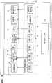
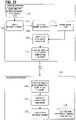
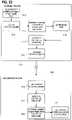
- Fig. 1shows a block diagram of a whole-body human-computer interface in accordance with one embodiment. Shown is a human-computer interface terminal 102 coupled to a computer system 104. The computer system 104, optionally, receives input states 120 from additional human-computer interface terminals associated with additional users.
- the human-computer interface terminal 102services at least one user, providing a user 106 that is sensed by a plurality of input transducers 108.
- the input transducers 108receive input from the user 106, and transduce that input to a user input state 112 preferably defined at a discrete time step n.
- the human-computer interface terminal 102receives a user output state 114 from the computer system 104, preferably defined at a discrete time step n+1.
- the user output state 114is transduced by the output transducers 110 to an appropriate form so as to stimulate one or more of the user's 106 sensory systems.
- a computer-mediated environment process 116receives the user input state 112, and maps one or more elements of that user input state to corresponding elements of a user avatar input state 150 via a mapping function 148.
- the user avatar input state 150is received by game/simulation engine process 152 and used to calculate the interaction of the user avatar with a computer-mediated environment.
- Elements of the game/simulation engine processinclude, for example, simulations of physical processes such as electromagnetism, acoustics, and dynamics that will be familiar to those skilled in the relevant art.
- the game/simulation engine process 152outputs a user avatar output state 154, and maps one or more elements of that user avatar output state 154 to corresponding elements of a user output state 114 via a mapping function 156.
- Additional input states 120include, in accordance with one embodiment, the input states of other human-computer interface terminals, or of other apparatus.
- Such apparatusoptionally affect or are affected by the physical world, as in "mixed-reality” or “augmented-reality” applications; for example: a user controls a machine by means of a user avatar representing that machine.
- the machinecontains one or more sensors which affect the state of computer-mediated environment process 116, and the machine contains one or more actuators which are affected by the user avatar output state 154.
- the user avataris of any morphology, not necessarily resembling the user, for example: being an arbitrary humanoid, animal, machine, or abstract form. Different avatars may be useful or preferred for different applications.
- a usermeans a user 106 of a human-computer interface terminal 102.
- a weareror “the wearer” is a user who is wearing a portion of a human-computer interface terminal 102 on his or her body. All descriptions are with respect to a user in the standard anatomical position, unless otherwise specified.
- an “inner” surfacemeans a surface nearer to a user's skin. Conversely, an “outer” surface means a surface farther away from a user's skin.
- two-point discrimination thresholdmeans: the minimum distance between two points of pressure stimuli applied to the skin surface of a user at which the user can reliably distinguish between said two points and a single point applying the same amount of total pressure.
- the two-point discrimination thresholdshould be understood to vary across the surface of the user's body based on the tactile sensitivity of a given portion of the user's skin.
- pressure-pain thresholdmeans: the minimum pressure applied to the skin surface of a user sufficient to induce pain. Like the two-point discrimination threshold, the pressure-pain threshold should be understood to vary across the surface of the user's body.
- workspacemeans: the set of reachable configurations of a mechanical or biological kinematic chain.
- Z-widthmeans: the range of mechanical impedances capable of being stably rendered by a haptic device.
- mechanical groundmeans: a point that is substantially fixed and immovable with respect to the user.
- the term "rigid structural material”means: steel, aluminum, titanium, amorphous metals, various other metals and metal alloys; thermoplastics and other polymers, oxide and non-oxide technical ceramics, other non-metals (such as glasses); composite constructions of the aforementioned metals and non-metals or other suitable materials, including carbon fiber reinforced polymer, fiberglass, and other reinforced polymers, sandwich type composites, and matrix-type composites; micro- and nano-structured constructions of the aforementioned metals and non-metals or other suitable materials, including cellular solids having a lattice, foam, honeycomb, or truss-based structure; or combinations of two or more of the above.
- the term "friction-reducing material”means: a solid, liquid, or other material having a low coefficient of friction in contact with a target material.
- examplesinclude: polytetrafluoroethylene or other fluoropolymers, or polyoxymethylene or other polymers; brass, bronze, steel, or other metals; composite constructions of the aforementioned metals and polymers or of other metals, polymers, ceramics, glasses, or other materials; liquid lubricants such as oil or grease; or combinations of two or more of the above.
- variable stiffness materialmeans: a material whose stiffness can be controllably varied - as by electrorheological, magnetorheological, fluidic, thermal, mechanical, electromagnetic, or other means, or by combinations of two or more of the above.
- contractile materialmeans: a metal, ceramic, polymer or other material that changes shape or size when exposed to varying temperatures, electric currents, or other stimuli, including: copper-based shape-memory alloys, nickel-titanium-based shape-memory alloys, or other types of shape-memory alloys; dielectric electroactive polymers, ionic electroactive polymers and polymer-metal composites, ferroelectric polymers, electrostrictive graft polymers, liquid crystal polymers, or another of the class of electroactive polymers; piezoelectric ceramics, piezoelectric polymers, or other piezoelectric materials; carbon nanotubes, graphene, or other carbon-based compounds; nylon fibers, polyethylene fibers or other polymer fibers; polydimethylsiloxane or other elastomers; or vanadium oxide; or combinations of two or more of the above.
- the term "flexible substrate material”means: a flexible and substantially gas and liquid impermeable material, preferably suitable for use with a soft lithography process. Examples include: polydimethylsiloxane or other elastomers; metal-filled elastomers or other metal-elastomer composites; ceramic-elastomer composites; carbon-filled elastomers or other carbon-elastomer composites; watertight fabrics, including metalized fabrics; or combinations of two or more of the above.
- a human-computer interface terminal 102comprises an exoskeleton.
- Said exoskeletoncomprises one or more actuated articulations 141 configured to apply a net force or torque 127 to a body segment of user 106.
- an exoskeletonalso comprises force or torque sensors 133, position or angle sensors 136, or biosignal sensors 135.
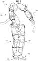
- Fig. 2generally depicts one embodiment of an exoskeleton.
- a plurality of structural membersare each coupled to at least one other structural member by one or more articulations.
- a plurality of locomotor modules(300 of Fig. 3 ) are configured to actuate one or more articulations of the exoskeleton.
- an exoskeletoncomprises a body-borne portion 703 operatively coupled to point-of-use portion 701 by means of one or more temporary coupling points 702a-710b.
- a structural memberis a load-bearing element configured to provide a substantially rigid load path.
- structural members of an exoskeletonare composed in part or whole of a rigid structural material.
- one or more structural membersare composed in part or whole of a variable stiffness material.
- Structural membersare generally shaped to minimize interference with a wearer's workspace while maintaining sufficient stiffness to provide a substantially rigid load path.
- a structural memberis shaped to enclose one or more portions of a wearer's body. Said member's inner surface is preferably substantially parallel to the wearer's skin surface throughout. Portions of the member are omitted around articulations of an exoskeleton where necessary to prevent interference with motion of the exoskeleton or wearer.
- Structural members of this typeare preferred to be employed in the extremities of an exoskeleton, as shown in Figs. 4A-B and Figs. 5A-B in accordance with one embodiment.
- Structural membersare preferred to be as thin as possible while maintaining sufficient stiffness to provide a substantially rigid load path, particularly those located in extremities of an exoskeleton.
- the thickness of structural members 401a/b, 405a/b ( Figs. 4A-B ) and 501a/b, 505a/b ( Figs. 5A-B )is between 0.20 and 5.0 mm.
- the thickness of structural members 401a/b, 405a/b ( Figs. 4A-B ) and 501a/b, 505a/b ( Figs. 5A-B )is between 0.50 and 2.5 mm.
- the thickness of structural members 401a/b, 405a/b ( Figs. 4A-B ) and 501a/b, 505a/b ( Fig. 5A-B )is between 1.0 and 2.0 mm.
- Articulations of an exoskeletonenable it to move with its wearer.
- the articulations of an exoskeletonare configured and positioned so as to permit an aggregate range of motion approximately equal to that of a wearer's body.
- Many articulationsare preferably positioned such that a center of rotation of the articulation is aligned with an average (best-fit) center of rotation of a corresponding biological joint.
- Revolute articulationscan be of a "pin type” having a center of rotation outside of the body of the wearer, or of a “rotary type” having a center of rotation inside of the body of the wearer.
- pin typehaving a center of rotation outside of the body of the wearer
- rotary typehaving a center of rotation inside of the body of the wearer.
- other basic kinematic pairssuch as prismatic, cylindrical, screw, planar, and spherical pairs
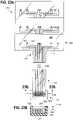
- FIG. 11an exploded view of a pin-type articulation of a structural exoskeleton actuated by a tensile member assembly of a locomotor module is shown in accordance with one embodiment.
- a proximal structural member 1102is coupled to a distal structural member 1104 by means of a pin 1110 so as to permit a single degree of rotational freedom about axis 1101.
- the distal structural member 1104comprises a pulley 1106.
- a tensile member 1116is coupled to the pulley 1106 via an inside termination (not shown), and to a first housing 1118 and second housing 1120. Housings 1118 and 1120 are coupled to distal structural member 1104 by means of housing terminations 1112 and 1114 respectively.
- Tensile load applied to either end of tensile member 1116will produce a rotational displacement of distal structural member 1104 relative to proximal structural member 1102 in opposite directions.
- Bushing or bearing element 1108prevents undue friction between proximal structural member 1102 and distal structural member 1104.
- FIG. 12Aa rotary-type articulation of a structural exoskeleton actuated by a tensile member assembly of a locomotor module is shown in accordance with one embodiment.
- FIG. 12Bshows an exploded view of the embodiment of Fig. 12A .
- a distal structural member 1204is coupled to a proximal structural member 1206 via a ball bearing and cage assembly 1208.
- a retaining member 1202is coupled first to distal structural member 1204 - via a ball bearing and cage assembly 1210 - and second to proximal structural member 1206.
- the combined assembly of elements 1202-1210permits a single degree of rotational freedom about axis 1201.
- a tensile member 1212is coupled to distal structural member 1204 via an inside termination (not shown), and to a first housing 1214 and second housing 1218. Housings 1214 and 1218 are coupled to retaining member 1202 by means of housing terminations 1220 and 1222 respectively. Tensile load applied to either end of tensile member 1212 will produce a rotational displacement in opposite directions of distal structural member 1204 relative to proximal structural member 1206 and retaining member 1202.
- a tensile member of a tensile member power transmission assemblycomprises a monofilament or multi-strand construction in various embodiments.
- a tensile memberpreferably comprises a flexible material having a high tensile strength, and capable of being formed into strands.
- contemplated materialsinclude: steel, or other metals; polyethylene (including ultra-high molecular weight polyethylene), aromatic polyamide, or other polymers; glass fiber; carbon fiber or other carbon-based materials; or a combination of two or more of the above.
- a housing of a tensile member power transmission assemblypreferably comprises a rigid structural material configured to be flexible in bending, but substantially stiff under compressive load.
- said rigid structural materialis arranged in a continuous structure, such as a single-, or multiple-helix wrapped around a tensile member.
- said rigid structural materialis arranged in a discontinuous structure, such as a plurality of close-packed tubes enclosing a tensile member.
- a housing of a tensile member power transmission assemblypreferably comprises an element, such as a coating or liner preferably comprising a friction-reducing material, configured to reduce friction between the housing and its tensile member.
- Tensile member diameteris preferably selected for a given tensile member such that the material elastic limit of the tensile member is greater than or equal to: the stress produced on said tensile member by the maximum allowed torque of the articulation to which it is coupled, multiplied by a safety factor of not less than 3.
- an articulationis of a continuum type e.g. comprising a "snake arm” or "elephant trunk” structure having a plurality of members coupled to a plurality of actuated degrees of freedom to form a hyper-redundant manipulator.
- one or more articulationsare composed in part or whole of a variable stiffness material.
- an articulationcomprises a multi-layer sliding spring mechanism configured to produce a bending torque in response to a linear input force.
- Joints of an exoskeletoncomprise one or more articulations.
- Embodiments of each jointare contemplated in which said joint comprises each of the following variations: a kinematic chain having fewer degrees of freedom than the biological joint or joints whose motion it is configured to emulate; a kinematic chain having an equal number of degrees of freedom to the biological joint or joint whose motion it is configured to emulate; a kinematic chain having a greater number of degrees of freedom than the biological joint or joints whose motion it is configured to emulate (i.e. a redundant kinematic chain); or a kinematic chain having a significantly greater number of degrees of freedom than the biological joint or joints whose motion it is configured to emulate (i.e. a hyper-redundant kinematic chain).
- a redundant or hyper-redundant kinematic chaincan provide an advantage in some embodiments by, for example: reducing potential kinematic singularities; increasing range or fidelity of motion; or permitting multiple configurations of a joint for a single end effector position.
- a limited number of the aforementioned variationsare described below for each joint; however, all suitable variations are contemplated for each joint, including kinematic chains having anywhere from zero to an infinite number of degrees of freedom in various configurations.
- One or more joints described hereinmay be omitted from an exoskeleton without departing from the scope of the present invention; however, omission of joints is anticipated to have a significant negative impact on the controllability and performance of an exoskeleton having one or more omitted joints. Additionally, omission of joints severely constrains the forces or torques that can safely be applied to the body of the wearer, as all forces or torques applied by the exoskeleton must be transmitted through the wearer's musculoskeletal system where joints are omitted.
- the combined structure of an arm segment 400a/b and any apparatus by which it is coupled to mechanical groundis sufficiently stiff to maintain a deflection of less than 30 mm under the following conditions: a load of 100 N is applied at the extreme distal point of arm segment 400a/b (e.g. the hand) along an axis perpendicular to the proximal-distal axis of the segment; deflection is measured as the displacement of the extreme distal point along said axis; all articulations of the structure are locked. In a more preferred embodiment, said deflection is less than 10 mm.
- the combined structure of a leg segment 500a/b and any apparatus by which it is coupled to mechanical groundis sufficiently stiff to maintain a deflection of less than 15 mm under the same test conditions described hereinabove. In a more preferred embodiment, said deflection is preferably less than 5.0 mm.
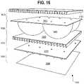
- Figs. 6A and 6Bshow a front and rear perspective view of a torso segment 600 of an exoskeleton in accordance with one embodiment.
- Torso segment 600comprises: pelvic structural member 604 and thoracic structural member 605, optionally coupled via a thoracic spinal joint 660; shoulder joints 670a, 670b or a portion thereof; and hip joints 650a, 650b or a portion thereof.
- Torso segment 600 of an exoskeletonis preferably coupled to mechanical ground by means of an elongated structural member 602. Alternately, any other suitable portion of an exoskeleton can be coupled to mechanical ground.
- Elongated structural member 602is optionally coupled to mechanical ground via a motion simulator (see “Motion Simulator” section) or other apparatus. Length of elongated structural member 602 is preferably selected to position any structures to which it is coupled (e.g. a motion simulator, actuator array, or other apparatus) outside or substantially outside the wearer's workspace.
- a motion simulatorsee “Motion Simulator” section
- Length of elongated structural member 602is preferably selected to position any structures to which it is coupled (e.g. a motion simulator, actuator array, or other apparatus) outside or substantially outside the wearer's workspace.
- a pelvic structural member 604 or a thoracic structural member 605are secured to the body of the wearer by an element (not shown) that encircles the wearer's pelvis or thorax respectively.
- the encircling elementcomprises one or more flexible portions, such as a fabric strap, a harness, a vest, or a belt.
- the encircling elementcomprises one or more portions consisting of a stiff structural material, such as a stiff band or plate.
- Pelvic structural member 604 and thoracic structural member 605are optionally coupled via thoracic spinal joint 660.
- Thoracic spinal joint 660is preferred to comprise a serial manipulator having at least 5 degrees of freedom.
- thoracic spinal joint 660comprises a serial manipulator having 5, 6, or 7 revolute articulations arranged in the manner of a robotic arm.
- Figs. 6A and 6Bshow an exemplary embodiment of a serial manipulator of this type.
- Articulation 619is coupled to articulation 620.
- Articulation 620is coupled, via structural member 608, to articulation 622.
- Articulation 622is in turn coupled to 3 degrees of freedom wrist assembly 624-628 via structural member 610.
- Lengths of structural members 608 and 610are preferably selected to enable full spinal flexion (i.e. where the wearer is touching his or her toes) at or near maximum extension of thoracic spinal joint 660.
- Other variations of the aforementioned embodiment of thoracic spinal joint 660 producing a similar aggregate range of motionare contemplated, including: variations wherein revolute articulations 619-628 are arranged in a different order; variations wherein some or all revolute articulations 619-628 are replaced with articulations comprising other basic kinematic pairs (such as prismatic, screw, or spherical pairs); variations wherein one or more portions of thoracic spinal joint 660 are arranged in a parallel, rather than serial, kinematic configuration; and variations wherein one or more portions of a thoracic spinal joint 660 comprise a continuum-type manipulator.
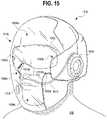
- the head of the wearercan optionally be coupled to one or more portions of an exoskeleton by a cervical spinal joint (not shown in Figs. 6A-B ), preferably of a substantially similar design to thoracic spinal joint 660 as described hereinabove.
- a cervical spinal jointnot shown in Figs. 6A-B
- thoracic spinal joint 660preferably of a substantially similar design to thoracic spinal joint 660 as described hereinabove.
- Figs. 6A and 6Bshow a right and left shoulder joint 670a and 670b in accordance with one embodiment.
- shoulder joint 670awhich will be described herein, is substantially equivalent to left shoulder joint 670b mirrored across the median plane of the body.
- shoulder joint 670acomprises a sternoclavicular joint 672a and a glenohumeral joint 674a.
- Sternoclavicular joint 672acomprises: a first articulation 630a configured to emulate motion of the wearer's scapula during scapular elevation and depression, and a second articulation 632a configured to emulate motion of the wearer's scapula during scapular protraction and retraction.
- Articulations 630a and 632apreferably each comprise a pin-type revolute articulation.
- Said pin-type revolute articulationspreferably have an axis of rotation substantially aligned with the average axis of rotation of the sternoclavicular joint of the wearer in scapular elevation/depression and scapular protraction/retraction respectively.
- a first contemplated means of alignmentcomprises adding a third articulation 634a to sternoclavicular joint 672a so as to enable three-degree-of-freedom positioning of glenohumeral joint 674a.
- a second contemplated means of alignmentcomprises placing articulation 632a above the head of the wearer.
- a third contemplated means of alignmentcomprises providing an external-center-of-rotation mechanism for articulation 632a.
- Said external-center-of-rotation mechanismcomprises, for example, a mechanism located behind the wearer's back producing a simultaneous rotation and translation that substantially replicates the motion of the wearer's sternoclavicular protraction and retraction without the need for a shared axis of rotation.
- a sternoclavicular joint 672acomprises only a single articulation 630a emulating elevation and depression of the wearer's scapula. Articulations providing for scapular protraction and retraction are omitted (owing to the relatively small motion of protraction and retraction), and the wearer's scapula is allowed to protract and retract freely relative to sternoclavicular joint 672a.
- articulation 630acomprises a prismatic or screw pair or other pair capable of producing linear motion, rather than a revolute pair.
- Glenohumeral joint 674apreferably comprises three revolute articulations having mutually intersecting axes of rotation, which are configured to emulate the motion of the glenohumeral joint of the wearer.
- torso segment 600comprises two pin-type revolute articulations 636a and 638a of a glenohumeral joint 674a.
- articulations 636a and 638aare coupled by means of an arc-shaped structural member 614a, and emulate via a compound motion the wearer's glenohumeral flexion/extension and adduction/abduction.
- Arc-shaped structural member 614ais preferred to be shaped so as to project as little as possible from the shoulder of the wearer without limiting the range of motion of the wearer or the exoskeleton.
- Articulation 414( Figs. 4A-B ) emulates the motion of the wearer's glenohumeral internal and external rotation. Articulation 414 is coupled to the rest of glenohumeral joint 670a by an upper arm structural member 402 ( Figs. 4A-B ).
- Axes of rotation of articulations 636a, 638a, and 414preferably approximately intersect the center of rotation of the glenohumeral joint of the wearer.
- a glenohumeral jointcomprises three revolute articulations with mutually intersecting axes of rotation, all of which are located in a torso segment of an exoskeleton.
- kinematic singularitiesDue to the large range of motion of the human glenohumeral joint, careful attention must be paid to placement of each articulation in order to avoid or minimize kinematic singularities.
- the axes of rotation of articulations 636a and 638aare angled so as to place kinematic singularities induced by motion of the wearer's shoulder in rarely used portions of the wearer's workspace.
- additional degrees of freedomare added to shoulder joint 670a in order to resolve or mitigate kinematic singularities in the wearer's workspace.
- Figs. 6A and 6Bshow a left and right hip joint 650a and 650b in accordance with one embodiment.
- right hip joint 650awhich will be described herein, is substantially equivalent to left hip joint 650b mirrored across the median plane of the body.
- Hip joint 650apreferably comprises three revolute articulations having mutually intersecting axes of rotation, which are configured to emulate the motion of the hip joint of the wearer.
- torso segment 600comprises two pin-type revolute articulations 616a and 618a of a hip joint 650a.
- articulations 616a and 618aare coupled by means of an arc-shaped structural member 617a, and emulate via a compound motion the wearer's hip flexion/extension and adduction/abduction.
- Arc-shaped structural member 617ais preferred to be shaped so as to project as little as possible from the hip of the wearer without limiting the range of motion of the wearer or the exoskeleton.
- Articulation 514( Figs. 5A-B ) emulates the wearer's hip internal and external rotation. Articulation 514 is coupled to the rest of hip joint 650a by an upper leg structural member 502 ( Figs. 5A-B ).
- Axes of rotation of articulations 616a, 618a, and 514preferably approximately intersect the center of rotation of the hip joint of the wearer.
- a hip jointcomprises three revolute articulations with mutually intersecting axes of rotation, all of which are located in a torso segment of an exoskeleton.
- the human hip jointdoes not have as large a range of motion as the human glenohumeral joint, careful attention must still be paid to placement of each articulation in order to avoid or minimize kinematic singularities.
- the axes of rotation of articulations 616a and 618aare angled so as to place kinematic singularities induced by motion of the wearer's hip in rarely used portions of the wearer's workspace.
- additional degrees of freedomare added to hip joint 650a in order to resolve or mitigate kinematic singularities in the wearer's workspace.
- Fig. 8shows one embodiment of a torso segment 600 of an exoskeleton in which a shoulder joint 670a/b comprises a serial manipulator having at least 5 degrees of freedom.
- a serial manipulator of a shoulder joint 670a/bcomprises 6 or 7 revolute articulations arranged in the manner of a robotic arm.
- Said serial manipulatorcomprises a base 802 coupled to structural member 804 via an articulation 814.
- Structural member 804is in turn coupled to structural member 806 via articulation 816.
- Structural member 806is coupled to structural member 808 via articulation 818.
- Structural member 808is in turn coupled to structural member 810 via articulation 820.
- Structural member 810is coupled to structural member 812 via articulation 822.
- the serial manipulatoris coupled to an upper arm structural member 401b by means of articulation 824.
- a serial manipulator of a shoulder joint 670a/b producing a similar aggregate range of motionincluding: variations wherein revolute articulations 814-824 are arranged in a different order; variations wherein some or all revolute articulations 814-824 are replaced with articulations comprising other basic kinematic pairs (such as prismatic or spherical pairs); variations wherein one or more portions of a serial manipulator are arranged in a parallel, rather than serial, kinematic configuration; and variations wherein one or more portions of a serial manipulator comprise a continuum-type manipulator.
- a hip joint 650a/b ( Figs. 6A-B ) of an exoskeletoncomprises a serial manipulator of the embodiment of Fig. 8 , or of another suitable type as described hereinabove.
- thoracic spinal articulation 660is omitted, and thoracic structural member 605 is not directly coupled to the wearer's torso.
- Structural member 605instead comprises a back support capable of supporting the wearer's thorax when sitting or lying down, but configured not to otherwise restrict the wearer's range of motion.
- a head supportis also included. Said head support is preferably configured to support the wearer's head when sitting or lying down, but not to otherwise restrict the wearer's range of motion.
- a back support or head supportcomprises a revolute articulation configured to allow the wearer's spine to extend while still supporting the wearer's head or back against the force of gravity.
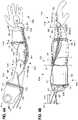
- a right arm segment 400a of an exoskeletoncan be seen, in accordance with one embodiment, in Figs. 4A-4B .
- left arm segment 400bwhile not shown in Figs. 4A-4B , is substantially equivalent to right arm segment 400a mirrored across the median plane of the body.
- An upper arm structural member 401a partially or completely enclosing the wearer's upper armis preferably coupled to a shoulder joint 670a ( Figs. 6A-B ) of a torso segment 600 ( Figs. 6A-B ).
- upper arm structural member 401ais bisected somewhere along the length of the wearer's upper arm substantially perpendicular to the proximal-distal axis by rotary-type articulation 414 of glenohumeral joint 674a ( Figs. 6A-B ) to form proximal and distal upper arm structural members 402 and 404.
- glenohumeral joint 674aFigs. 6A-B
- internal and external rotation of the wearer's shoulderis enabled by an articulation of torso segment 600 ( Figs. 6A-B ), and thus no bisection of upper arm structural member 401a is required.
- Portions of upper arm structural member 401aare preferably omitted around the wearer's glenohumeral joint and elbow joint to avoid interfering with the motion of these joints.
- the proximal boundary 436 of upper arm structural member 401ais preferably delimited approximately by the acromion process of the wearer's scapula.
- Proximal edge 438 of upper arm structural member 401ais preferably shaped so as to avoid the wearer's underarm.
- Distal edge 440preferably follows approximately the arc formed on the wearer's upper arm by the edge of skin-to-skin contact of the wearer's forearm and upper arm at the point of extreme flexion of the wearer's elbow.
- Distal boundary 442is preferably delimited approximately by the olecranon process of the wearer's elbow.
- a portion of upper arm structural member 401a or articulation 414is preferred to completely encircle the wearer's upper arm to lend additional torsional rigidity to the structural member; however, embodiments are contemplated of upper arm structural member 401a where the structural member or its articulations only partially encircle the wearer's upper arm. In one example, articulation 414 only partially encircles the wearer's upper arm.
- an upper arm structural member 401acomprises a length adjustment mechanism (not shown), preferably located near elbow joint 415a.
- An upper arm structural member 401aoptionally also comprises a mechanism that adjusts upper arm structural member's 401a angle relative to forearm structural member 405a to account for variation in carrying angle of a wearer's elbow.
- Said angle adjustment mechanismis preferably located near elbow joint 415a.
- a distal portion of upper arm structural member 401ais coupled by means of an elbow joint 415a to a forearm structural member 405a partially or completely enclosing the wearer's forearm.
- Elbow joint 415apreferably comprises one or more pin-type articulations 416 having an axis of rotation substantially aligned with the average axis of rotation of the elbow joint in flexion/extension.
- Articulations 416 of elbow joint 415aare preferably configured with pin-type revolute articulations both medial and lateral to the wearer's elbow for increased strength and rigidity.
- elbow joint 415acomprises only a single pin-type revolute articulation, preferably located lateral to elbow joint 415a.
- Forearm structural member 405ais preferably bisected somewhere along the length of the wearer's forearm substantially perpendicular to the proximal-distal axis by a rotary-type articulation 418 allowing for pronation and supination of the wearer's wrist. Bisection of forearm structural member 405a forms proximal and distal forearm structural members 406 and 408.
- a forearm structural member 405acomprises a length adjustment mechanism (not shown), preferably located near elbow joint 415a.
- Portions of forearm structural member 405aare preferably omitted around the wearer's elbow joint and wrist joint to avoid interfering with the motion of these joints.
- the proximal boundary 444 of forearm structural member 405ais preferably delimited approximately by the olecranon process of the wearer's elbow (with some additional room left between the distal edge of upper arm structural member 401a and the proximal edge of forearm structural member 405a to allow for full extension of the wearer's elbow).
- Proximal edge 446 of forearm structural member 405apreferably follows approximately the arc formed on the wearer's forearm by the edge of skin-to-skin contact of the wearer's forearm and upper arm at the point of extreme flexion of the wearer's elbow.
- Distal edge 447 of forearm structural member 405ais preferably shaped so as to leave an opening of a sufficient size to permit passing the hand of the wearer through during donning and removal of the exoskeleton.
- a structural discontinuity sufficient to permit passing the hand of the wearer through and an accompanying fasteneris included in the distal portion of forearm structural member 405a.
- Distal boundary 448is preferably approximately delimited by the ulnar styloid process of the wearer's wrist.
- a portion of forearm structural member 405a or articulation 418is preferred to completely encircle the wearer's forearm to lend additional torsional rigidity to the structural member; however, embodiments are contemplated of forearm structural member 405a where the structural member or its articulations only partially encircle the wearer's forearm. In one example, articulation 418 only partially encircles the wearer's forearm.
- a distal portion of forearm structural member 405ais coupled by means of a wrist joint 419a to an opisthenar structural member 412 partially or completely overlying the wearer's second through fifth metacarpals.
- wrist joint 419acomprises a first pin-type revolute articulation 420 coupled to a second pin-type revolute articulation 422 by means of structural member 421.
- An axis of rotation of articulation 420is preferably substantially aligned with the average axis of rotation of the wearer's wrist in flexion/extension.
- An axis of rotation of articulation 422is preferably substantially aligned with the average axis of rotation of the wearer's wrist in radial/ulnar deviation.
- Structural member 421is preferred to be shaped so as to project as little from the wrist of the wearer as possible without limiting the range of motion of the wearer or the exoskeleton.
- proximal boundary 450 of opisthenar structural member 412is preferably delimited approximately by the radial styloid process of the wearer's wrist.
- Distal boundary 452is preferably delimited approximately by the proximal edge of the metacarpophalangeal joints of the wearer's second through fifth metacarpals.
- Medial and lateral boundaries of opisthenar structural member 412are preferably delimited approximately by the outside edges of the wearer's second and fifth metacarpal respectively.
- an opisthenar structural member 412comprises a length adjustment mechanism (not shown), preferably located near wrist joint 419a.
- a hand segment 204a/bFig.
- an exoskeletoncomprises an opisthenar structural member 412 and a means of securing the opisthenar structural member 412 to the wearer's hand (not shown in Figs. 4A-4B ).
- Said meanscan, for example, comprise a strap, band, glove, brace, or similar element.
- a second embodiment of a hand segment 204a/bis shown.
- Opisthenar structural member 412is coupled to thumb proximal phalangeal structural member 920 via thumb metacarpophalangeal joint 939.
- Thumb metacarpophalangeal joint 939preferably comprises two pin-type revolute articulations 942 and 944, whose compound motion emulates flexion/extension and abduction/adduction of the metacarpophalangeal joint of the wearer's thumb.
- Articulation 934is coupled to articulation 942 via an arc-shaped structural member 919.
- Arc-shaped structural member 919is preferred to be shaped so as to project as little as possible from the hand of the wearer without limiting the range of motion of the wearer or the exoskeleton.
- Thumb proximal phalangeal structural member 920is coupled to thumb intermediate phalangeal structural member 922 via thumb proximal interphalangeal joint 935.
- Thumb proximal interphalangeal joint 935preferably comprises one or more pin-type articulations 936, 937 having an axis of rotation substantially aligned with the average axis of rotation of the proximal interphalangeal joint of the wearer's thumb in flexion/extension.
- Articulations 936, 937 of thumb proximal interphalangeal joint 935are preferably configured with pin-type revolute articulations both medial and lateral to the wearer's thumb for increased strength and rigidity.
- thumb proximal interphalangeal joint 935comprises only a single pin-type revolute articulation.
- Thumb intermediate phalangeal structural member 922is coupled to thumb distal phalangeal structural member 924 via thumb distal interphalangeal joint 938.
- Thumb distal interphalangeal joint 938is preferably substantially similar to thumb proximal interphalangeal joint 936 as described hereinabove.
- Opisthenar structural member 412is coupled to index finger proximal phalangeal structural member 914 and a middle finger proximal phalangeal structural member (not shown) via finger metacarpophalangeal joint 925.
- Finger metacarpophalangeal joint 925preferably comprises: a first pin-type revolute articulation 928 - having an axis of rotation substantially aligned with the average axis of rotation of the wearer's index finger in flexion/extension - coupled to a second pin-type revolute articulation 930 - having an axis of rotation substantially aligned with the average axis of rotation of the wearer's index finger in abduction/adduction.
- Metacarpophalangeal joint 925preferably also comprises: a third pin-type revolute articulation 926 - having an axis of rotation substantially aligned with the average axis of rotation of the wearer's middle finger in flexion/extension - coupled by means of a metacarpophalangeal structural member 917 to a fourth pin-type revolute articulation (not shown) - having an axis of rotation substantially aligned with the average axis of rotation of the wearer's middle finger in abduction/adduction.
- Metacarpophalangeal structural member 917is preferably positioned and shaped to project as little as possible from the hand of the wearer without limiting the range of motion of the wearer or the exoskeleton.
- metacarpophalangeal structural member 917is preferably positioned and shaped to project as little as possible from the hand of the wearer without colliding with the top of the proximal phalanx of the wearer's index finger in simultaneous hyperextension of the metacarpophalangeal joint of the wearer's index finger and flexion of the metacarpophalangeal joint of the wearer's middle finger.
- Structural members 914-918 and joints 931 and 933 of index finger segment 950, as well as the equivalent structural members and joints of a middle finger segment (not shown)are preferably substantially similar to thumb structural members 920-924 and thumb joints 936 and 938, as described hereinabove.
- Structural members, joints, and articulations of a pinky finger and ring fingerare preferably substantially similar to the structural members, joints, and articulations of the index and middle finger segments respectively, as described hereinabove.
- a deviceis provided to be held in the wearer's hand.
- Said deviceis preferably coupled to opisthenar structural member 412 ( Figs. 4A-4B ).
- said devicecomprises a controller, such as a game controller.
- This controllerpreferably comprises at least one input transducer, such as a button, which can be used to provide input to a computer-mediated environment process 116 ( Fig. 1 ).
- said hand-held devicecomprises a "prop," such as a gun, sword, or medical instrument that represents a corresponding article in a computer-mediated environment process 116 ( Fig. 1 ).
- This proplikewise optionally comprises one or more input transducers, such as a trigger, which can be used to provide input to a computer-mediated environment process 116 ( Fig. 1 ).
- said hand-held devicecomprises a handle or other stiff projection that can be enclosed by the hand of the wearer.
- a hand segment 204a/bcomprises one or more articulations coupled to opisthenar structural member 412 ( Figs. 4A-4B ) and configured to produce a force or torque on one or more of the wearer's fingers or phalanges thereof.
- one or more articulations of a hand segment 204a/bcomprise a multi-layer sliding spring mechanism. Said mechanism is preferably configured to produce a compound bending motion similar to that of combined motion of the wearer's metacarpophalangeal, proximal interphalangeal, and distal interphalangeal joints in flexion and extension of a finger of the wearer.
- the multi-layer sliding spring mechanismis coupled to a pin-type revolute articulation in order to emulate abduction/adduction of a metacarpophalangeal joint of the wearer.
- Said pin-type revolute articulationpreferably has an axis of rotation substantially aligned with the average axis of rotation of a metacarpophalangeal joint of the wearer in abduction/adduction of a finger of the wearer.
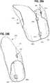
- a right leg segment 500a of an exoskeletoncan be seen, in accordance with one embodiment, in Figs. 5A-B .
- left leg segment 500bwhile not shown in Figs. 5A-B , is substantially equivalent to right leg segment 500a mirrored across the median plane of the body.
- An upper leg structural member 501a partially or completely enclosing the wearer's upper legis preferably coupled to a hip joint 650a ( Figs. 6A-B ) of a torso segment 600 ( Figs. 6A-B ).
- upper leg structural member 501ais bisected somewhere along the length of the wearer's upper leg substantially perpendicular to the proximal-distal axis by rotary-type articulation 514 of hip joint 650a ( Figs. 6A-B ) to form proximal and distal upper leg structural members 502 and 504.
- hip joint 650aFigs. 6A-B
- internal and external rotation of the wearer's hipis enabled by an articulation of torso segment 600 ( Figs. 6A-B ), and thus no bisection of upper leg structural member 501a is required.
- Portions of upper leg structural member 501aare preferably omitted around the wearer's hip joint and knee joint to avoid interfering with the motion of these joints.
- the proximal boundary 536 of upper leg structural member 501ais preferably delimited approximately by the greater trochanter of the wearer's femur.
- Proximal edge 538 of upper leg structural member 501ais preferably shaped so as to avoid the wearer's groin.
- Distal edge 540preferably follows approximately the arc formed on the wearer's upper leg by the edge of skin-to-skin contact of the wearer's lower leg and upper leg at the point of extreme flexion of the wearer's knee.
- Distal boundary 542is preferably delimited approximately by the lateral epicondyle of the wearer's femur.
- a portion of upper leg structural member 501a or articulation 514is preferred to completely encircle the wearer's upper leg to lend additional torsional rigidity to the structural member; however, embodiments are contemplated of upper leg structural member 501a where the structural member or its articulations only partially encircle the wearer's upper leg. In one example, articulation 514 only partially encircles the wearer's upper leg.
- an upper leg structural member 501acomprises a length adjustment mechanism (not shown), preferably located near knee joint 515a.
- Knee joint 515apreferably comprises one or more pin-type articulations 516 having an axis of rotation substantially aligned with the average axis of rotation of the wearer's knee joint in flexion/extension.
- Articulations 516 of knee joint 515aare preferably configured with pin-type revolute articulations both medial and lateral to the wearer's knee for increased strength and rigidity.
- knee joint 515acomprises only a single pin-type revolute articulation, preferably located lateral to knee joint 515a.
- knee joint 515acomprises a four-bar mechanism producing a simultaneous rotation and translation configured to approximately follow the corresponding rotation and translation of the wearer's knee joint in flexion/extension.
- Lower leg structural member 505ais optionally bisected somewhere along the length of the wearer's lower leg substantially perpendicular to the proximal-distal axis by a rotary-type articulation 518 allowing for internal and external rotation of the wearer's knee.
- Optional bisection of lower leg structural member 505aforms proximal and distal lower leg structural members 506 and 508.
- internal and external rotation of the wearer's kneeis accommodated by motion of other articulations such as those of hip joint 650a ( Figs. 6A-B ) or ankle joint 519a and thus no bisection of lower leg structural member 505a is required.
- a lower leg structural member 505acomprises a length adjustment mechanism (not shown), preferably located near knee joint 515a.
- lower leg structural member 505aPortions of lower leg structural member 505a are preferably omitted around the wearer's knee joint and ankle joint to avoid interfering with the motion of these joints.
- the proximal boundary 544 of lower leg structural member 505ais preferably delimited approximately by the lateral epicondyle of the wearer's femur (with some additional room left between the distal edge of upper leg structural member 501a and the proximal edge of lower leg structural member 505a to allow for full extension of the wearer's knee).
- Proximal edge 546 of lower leg structural member 505apreferably follows approximately the arc formed on the wearer's lower leg by the edge of skin-to-skin contact of the wearer's lower leg and upper leg at the point of extreme flexion of the wearer's knee.
- Distal edge 547 of lower leg structural member 505apreferably is shaped so as to leave an opening of a sufficient size to permit passing the foot of the wearer through during donning and removal of the exoskeleton.
- a structural discontinuity sufficient to permit passing the foot of the wearer through and an accompanying fasteneris included in the distal portion of lower leg structural member 505a.
- Distal boundary 548 of lower leg structural member 505ais preferably delimited approximately by the lateral malleolus of the wearer's fibula.
- a portion of lower leg structural member 505a or articulation 518is preferred to completely encircle the wearer's lower leg to lend additional torsional rigidity to the structural member; however, embodiments are contemplated of lower leg structural member 505a where the structural member or its articulations only partially encircle the wearer's lower leg.
- ankle joint 519acomprises a first pin-type revolute articulation 520 coupled to a second pin-type revolute articulation 522 by means of structural member 521.
- An axis of rotation of articulation 520is preferably substantially aligned with the average axis of rotation of the wearer's ankle in dorsiflexion/plantarflexion.
- An axis of rotation of articulation 522is preferably substantially aligned with the average axis of rotation of the wearer's ankle in inversion/eversion.
- Structural member 521is preferred to be shaped so as to project as little from the ankle of the wearer as possible without limiting the range of motion of the wearer or the exoskeleton.
- foot segment 512acomprises a shoe with a stiff, load-bearing portion 510 (preferably the sole) that is coupled to the foot of the wearer.
- the other elements of foot segment 512acomprise any suitable combination of straps or bands (in the manner of a sandal), or an "upper” composed of any of a variety of suitable materials with one or more fasteners such as laces, Velcro, or buckles (in the manner of an athletic shoe or boot).
- foot segment 512acomprises a load-bearing portion 510 (again preferably the sole), and one or more fasteners for securing a separate shoe or other foot covering to the load-bearing portion 510 of foot segment 512a.
- foot segment 512acomprises a length adjustment mechanism (not shown), preferably located near ankle joint 519a.
- the bottom of foot segment 512ais optionally lined or coated with a variety of functional materials.
- a durable coating of a materialsuch as rubber with or without grooves or treads is applied to increase traction.
- a friction-reducing materialis applied to facilitate use of an exoskeleton with a supplementary support surface 1416 ( Fig. 14 ; see "Motion Simulator" section).
- one or more separate toe segmentsare coupled by means of one or more metatarsophalangeal articulations to load-bearing portion 510.
- a first toe segmentpartially or completely overlies the hallux, and a second toe segment partially or completely overlies the remaining toes.
- FIG. 3shows a block diagram of a locomotor module 300 in accordance with one embodiment.
- An actuator assembly 306 -comprising one or more actuators driven by a power supply 302 - is coupled to an actuated articulation 324 by a power transmission system 320.
- a first sensor package 312senses the position, angle, force, or torque at actuator assembly 306 by means of a position or angle sensor 314 or a force or torque sensor 316.
- a second sensor package 326optionally senses the position, angle, force, or torque at actuated articulation 324 by means of a position or angle sensor 328 or a force or torque sensor 330.
- the second sensor package 326optionally also includes a biosignal sensor 332, such as an electrode suitable for surface electromyography that is configured to contact the wearer's skin.
- a first safety featurecomprises a current or pressure limiter 304 which prevents power supply 302 from transmitting excessive power to actuator assembly 306.
- a second safety featurecomprises a force or torque limiter 318 which prevents actuator assembly 306 from transmitting excessive force or torque to power transmission system 320.
- a third safety featurecomprises a position or angle limiter that prevents actuated articulation 324 from reaching a position or angle which could injure the wearer's joints.
- actuator assembly 306comprises one or more contractile actuators, such as one of the class of "artificial muscles.”
- a contractile actuator of actuator assembly 306comprises a McKibben-type artificial muscle comprising an expandable inner tube surrounded by an outer braided sheath. This assembly is closed off at one end and coupled to a tension member. The other end is coupled to a pressurized fluid line. When working fluid is allowed into the muscle, the flexible inner tube expands in diameter. This applies tension to the sheath and causes the artificial muscle fiber to contract in length, thus applying a controllable tensile force to the tensile member.
- a contractile actuator of actuator assembly 306comprises a contractile material.
- the displacement of a contractile actuator of actuator assembly 306is amplified by twisting the material of the actuator.
- a number of small-diameter artificial muscle fibersare ganged together into a muscle bundle so as to arbitrarily increase total power output. Said muscle bundle is, for example, arranged in a largely planar fashion around the outside surface of an exoskeleton.
- actuator assembly 306comprises one or more electromechanical actuators, such as a brushed or brushless DC motor, or an AC induction or synchronous motor.
- a speed reduction mechanismis preferably used to increase the torque output of an electromechanical actuator.
- a speed reduction mechanismcomprises a continuous, cable-driven mechanism.
- a speed reduction mechanismcomprises a gearbox, such as a strain wave, planetary, or spur gearbox.
- actuator assembly 306comprises one or more series-elastic elements, such as a spring, between the actuator 308, 310 and the actuated articulation 324 for improved force control.
- actuator assembly 306comprises one or more variable stiffness or variable impedance actuators, preferably comprising a variable stiffness material.
- one or more variable stiffness or variable impedance actuatorsare used to join one or more structural members in place of or in addition to one or more articulations.
- Power supply 302 and current/pressure limiter 304are chosen to be compatible with the selected actuator or actuators.
- an electrical power supply and a circuit breaker or fuse respectivelyis used with an electromechanical actuator or other electrically driven actuator, while a pressurized pneumatic or hydraulic supply and a relief valve or burst disc respectively is used with a fluidic actuator.
- Actuator assembly 306optionally includes multiple actuators in a variety of configurations.
- two coupled actuators 308 and 310are configured to independently regulate both the force or torque and the damping of an actuated articulation 324. Independent control of damping may provide numerous advantages including an increased Z-width, increased maximum resistive force or torque at actuated articulation 324, and reduced power consumption with some actuator types.
- two contractile actuatorsare arranged into an agonist-antagonist pair acting in tension on actuated articulation 324.
- Force or torque in one directioncan be regulated by actuating the first actuator and relaxing the second; force or torque in the opposite direction can be regulated by doing the reverse.
- Damping of the actuated articulation 324can be regulated by actuating both actuators equally to a varying degree.
- an actuatoris coupled to a resistive mechanism such as an electromagnetic brake (including a friction-plate brake, particle brake, hysteresis power brake, magnetorheological brake, or eddy current brake) or a non-electromagnetic brake (including a piezoelectric brake or electrorheological brake).
- a resistive mechanismsuch as an electromagnetic brake (including a friction-plate brake, particle brake, hysteresis power brake, magnetorheological brake, or eddy current brake) or a non-electromagnetic brake (including a piezoelectric brake or electrorheological brake).
- Position or angle sensors 314, 328can be placed anywhere within a locomotor module in any combination.
- a first embodiment of a position or angle sensorcomprises: a plurality of optical, acoustic, magnetic, or radio frequency markers located on an exoskeleton; and one or more externally located devices which transduce the 3D position of the markers to a computer-interpretable form in real time.
- a second embodimentcomprises an inertial sensor such as an accelerometer or gyroscope coupled to one or more segments of an exoskeleton to measure linear and/or rotational acceleration of a portion of the exoskeleton.
- magnetometersare placed adjacent to small permanent magnets on opposite sides of an articulation of an exoskeleton.
- a potentiometer, encoder, or other goniometeris utilized to transduce the angle or position of an actuator, actuator assembly, or articulation of an exoskeleton to which it is attached.
- a magnetometeris used to sense a magnetic field originating externally to an exoskeleton (such as magnetic north) to ascertain orientation, or an accelerometer or inclinometer is used to ascertain orientation relative to the gravity vector.
- Force or torque sensors 316, 330can also be placed anywhere within a locomotor module in any combination.
- force or torque sensors 316, 330comprise a strain gauge (such as a foil, semiconductor, thin film, or wire strain gauge), piezoelectric sensor (such as a piezoelectric crystal or piezoelectric film sensor), or other type of sensor (such as a linear variable differential transformer, capacitive displacement sensor, optical sensor, magneto-elastic device, or vibrating element force transducer).
- the force or torque to be measuredacts on one or more intermediate elements, rather than directly acting on the aforementioned sensors.
- a linear variable differential transformeris used to measure the displacement of a spring (with a known spring constant) under load in order to approximate the force acting on the spring.
- deformation of a structural member of an exoskeletonis measured by means of e.g. a strain gauge in order to approximate the force or torque acting on the structural member.
- the force or torqueis derived from measurement of the power flowing into or out of an actuator assembly 306. For instance, the current flowing into an electromechanical actuator is measured to estimate the force or torque output of said actuator.
- force or torque limiter 318comprises a mechanism that predictably disconnects, breaks, or slips under a given force or torque.
- Examplesinclude mechanical devices (such as a shear pin, a ball detent, a pawl and spring or a friction plate) and nonmechanical devices (such as a magnetic coupling or magnetic clutch).
- a power transmission system 320transfers power between portions of a locomotor system - especially between actuator assembly 306 and actuated articulation 324 - by mechanical, fluidic, electrical, or other means.
- Power transmission systemscan be placed anywhere within a locomotor system in any combination.
- a power transmission system 320enables one or more articulations 324 to be remotely actuated - i.e. actuated by an actuator assembly 306 located some distance away. Remote actuation is preferred for many actuated articulations 324 in order to reduce the size and mass of the exoskeleton.
- a portion of one or more locomotor modules 300are advantageously located away from the body of the wearer, preferably within housing 1403 ( Fig. 14 ).
- Directly actuated articulations - i.e. articulations that are directly coupled to an actuator assembly 306 -do not require a power transmission system 320 between the actuator assembly 306 and actuated articulation 324.
- actuator assembly 306is coupled to actuated articulation 324 by one or more tensile member assemblies.
- Tensile member assembliesare preferably grouped into agonist-antagonist pairs.
- a housing of a tensile member assemblyis preferably positioned and routed so as to minimize the total angular displacement of the distal end of said housing relative to the proximal end.
- each tensile member assemblyis selectively secured to one or more of the structural members along its run so as to delimit a preferred path for the tensile member assembly.
- one or more pulleysare used to redirect a tensile member instead of, or in combination with, one or more housings in order to reduce friction.
- Said pulleysare preferably arranged such that a first idler pulley and a second idler pulley rotate relative to each other about the axis of rotation of a primary pulley.
- a first tensile member and second tensile memberare preferably configured to cross over each other between the first idler pulley and the primary pulley, and again between the primary pulley and the second idler pulley.
- a power transmission system 320comprises a fluidic transmission system that supplies a pressurized working fluid to actuate one or more fluidic actuators of a rotary, cylinder, artificial-muscle, or other type.
- Fluidic linesare preferably arranged in a similar manner to the tensile members shown in Figs. 2 , 4A-5B , and 7 .
- a fluidic lineis preferably selectively secured to one or more of the structural members or articulations along its run so as to delimit a preferred path for the line.
- a position or angle limiter 322is included.
- Position or angle limiter 322is preferred to comprise a mechanical device that physically stops actuated articulation 324 from reaching an unsafe position or angle.
- a torso segment 600 of an exoskeletonare preferred to be directly actuated, as they are anticipated to be positioned substantially outside the workspace of the wearer; however, distal articulations of a shoulder joint or hip joint of an exoskeleton are preferred to be remotely actuated to minimize interference with the wearer's workspace.
- shoulder joint 670a/bhip joint 650a/b or thoracic spinal joint 660, a position or angle sensor, a force or torque sensor, or a force or torque limiter is located at each articulation.
- a multiple-degree-of-freedom position or angle senor, a multi-axis force or torque sensor, or a force or torque limiteris located at the distal end of shoulder joint 670a/b, hip joint 650a/b or thoracic spinal joint 660.
- a serial manipulator 660, 802-824Fig. 8
- a position or angle limiter, a force or torque limiter, or other suitable meansis provided to prevent harmful collision of parts of a serial manipulator with the wearer's body.
- Power transmission elements(not shown in Figs.
- FIGs. 4A-4Blocomotor systems of a right arm segment 400a of an exoskeleton are shown in accordance with one embodiment.
- the embodiment of Figs. 4A-4Bdepicts a tensile-member-based power transmission system, placement and routing of fluidic lines for a fluidic power transmission system is anticipated to be substantially similar.
- Radial or ulnar deviation of wrist articulation 422is produced by the action of tensile member assemblies 434a and 434b respectively.
- Flexion or extension of wrist articulation 420is produced by the action of tensile member assemblies 432a and 432b respectively.
- Pronation or supination of articulation 418is produced by the action of tensile member assemblies 430a and 430b respectively.
- Tensile member assembly 430bis secured to upper arm structural member 401a by anchor point 431.
- Tensile member assemblies 430a and 432a-434bare secured to upper arm structural member 401a by anchor point 429.
- Flexion or extension of elbow articulation 416is produced by the action of tensile member assemblies 428a and 428b respectively.
- Tensile member assemblies 428a-434bare coupled to form tensile member assembly bundle 427.
- Internal or external rotation of shoulder articulation 414is produced by the action of tensile member assemblies 426a and 426b respectively.
- Tensile member assemblies 426a and 426bare coupled to form tensile member assembly bundle 425.
- tensile member assembly bundles 425, 427 of right arm segment 400aterminate on or near upper arm structural member 401a. In another embodiment, tensile member assembly bundles terminate on the back of the wearer.
- Tensile member assembly bundles 425 and 427are preferably routed to a point near the shoulder blades of the wearer. Said routing preferably follows a path configured to minimize angular displacement of the distal end of said bundles (e.g. anchor points 429 and 431) in a common posture of the wearer's arms (i.e. where the wearer's shoulders are angled as they would be when holding a small object approximately 20 cm out from the wearer's abdomen approximately level with the wearer's solar plexus).
- tensile member assemblies 430a-434b of a forearm segment or tensile member assemblies of a hand segment 204a/bare coupled to one or more pulleys having a center of rotation substantially aligned with the average center of rotation of the wearer's elbow in flexion/extension.
- a hand segment 204a/b ( Fig. 2 ) of an exoskeletoncomprises one or more tensile members of a power transmission system 320 ( Fig. 3 ) configured to produce a net force or torque on one or more of the wearer's fingers or the phalanges thereof.
- tensile membersare secured to the opisthenar and palmar surfaces of one or more phalanges of a finger by one or more anchor points.
- articulations of a hand segment 204a/bare omitted, allowing one or more tensile members to act directly on the wearer's joints.
- a multi-layer sliding spring mechanismis actuated by means of a mechanism that comprises: a first tensile member configured to produce a force on the sliding spring mechanism sufficient to induce bending in one direction; and a spring or second tensile member, acting in opposition to the first tensile member, configured to induce bending in the opposite direction.
- FIG. 5A-Blocomotor systems of a right leg segment 500a of an exoskeleton are shown in accordance with one embodiment.
- FIGs. 5A-Bdepicts a tensile-member-based power transmission system, placement and routing of fluidic lines for a fluidic power transmission system is anticipated to be substantially similar.
- Inversion or eversion of ankle articulation 522is produced by the action of tensile member assemblies 534a and 534b respectively.
- Dorsiflexion or plantarflexion of ankle articulation 520is produced by the action of tensile member assemblies 532a and 532b respectively.
- Internal or external rotation of articulation 518is produced by the action of tensile member assemblies 530a and 530b respectively.
- Flexion or extension of knee articulation 516is produced by the action of tensile member assembly 528a and 528b respectively.
- Internal or external rotation of hip articulation 514is produced by the action of tensile member assemblies 526a and 526b respectively.
- Tensile member assemblies of right leg segment 500aare coupled to form tensile member assembly bundle 527.
- tensile member assembly bundles 525, 527 of right leg segment 500aterminate on or near upper leg structural member 501a. In another embodiment, tensile member assembly bundles terminate on the back of the wearer.
- Tensile member assembly bundles 525 and 527are preferably routed to a point near the sacrum of the wearer. Said routing preferably follows a path configured to minimize angular displacement of the distal end of said bundles in a common posture of the wearer's legs (i.e. where the wearer's hips are angled as they would be when standing straight up).
- tensile member assemblies 530a-534b of a lower leg segment or tensile member assemblies of a foot segment 512a/bare coupled to one or more pulleys having a center of rotation substantially aligned with the average center of rotation of the wearer's knee in flexion/extension.
- a foot segment 512a/b ( Figs. 5A-B ) of an exoskeletoncomprises one or more tensile members of a power transmission system 320 ( Fig. 3 ) configured to produce a net force or torque on one or more of the wearer's toes.
- tensile membersare secured to the plantar and dorsal surfaces of one or more toes by one or more anchor points.
- articulations of a foot segment 512a/bare omitted, allowing one or more tensile members to act directly on the wearer's joints.
- Fig. 7shows an exoskeleton in accordance with a preferred embodiment.
- the exoskeletoncomprises: a point-of-use portion 701 located at the intended point of use of the human-computer interface terminal 102 ( Fig. 1 ) of which the exoskeleton is a part, and a body-borne portion 703 worn on the body of a user.
- the point-of-use portion 701is configured to be transitively coupled to one or more body-borne portions 703 so as to form an operative exoskeleton. Having a point-of-use portion 701 configured to be transitively coupled to one or more body-borne portions 703 allows multiple users 100 ( Fig.
- Body-borne portion 703is operatively coupled to point-of-use portion 701 by means of one or more temporary coupling points 702a-710b.
- temporary coupling points 702a-710bcomprise power-transmission couplings (of fluidic, electrical, tensile-member, or other types), or non-power-transmission couplings (such as mechanical couplings or data transmission couplings).
- Temporary coupling points 702a-710bare preferably located so as to minimize interference of the coupling points with free movement of the wearer or exoskeleton.
- a temporary coupling pointcomprises a mechanical coupling that attaches a point-of-use portion 701 of an exoskeleton to a body-borne portion 703 of an exoskeleton to form a composite load-bearing structure.
- a mechanical coupling of a temporary coupling pointis preferably composed in whole or in part of a rigid structural material.
- Figs. 10A and 10Bshow a mechanical coupling 1000 of a temporary coupling point in accordance with one embodiment.
- Mechanical coupling 1000comprises: a female connector 1001, preferably located on a body-borne portion 703 of an exoskeleton; and a male connector 1002, preferably located on a point-of-use portion 701 of an exoskeleton.
- Female connector 1001comprises: a ring member 1006 having a groove 1007 configured to receive a plurality of locking balls 1016; and one or more receptacles 1008, each configured to receive a pin 1018.
- Male connector 1002comprises: a plurality of locking balls 1016, each positioned adjacent to a corresponding hole 1017 in member 1010; and a plunger 1012 having a groove 1014 configured to receive a plurality of locking balls 1016.
- Pins 1018 in receptacles 1008prevent rotation of the two connectors relative to one another. In order to uncouple the male connector 1002 from the female connector 1001, locking force is removed from plunger 1012, thereby allowing the two connectors to be separated.
- a mechanical coupling of a temporary coupling pointcomprises a hook and loop fastener, threaded fastener, buckle, button, clasp, clamp, latch, pin, strap, tie, zipper, anchor, snap, or other mechanically mated temporary fastener, or a combination of two or more of the above.
- a mechanical coupling of a temporary coupling pointcomprises a dry or wet adhesive or other chemically mated temporary fastener.
- a mechanical coupling of a temporary coupling pointcomprises a suction cup or other temporary fastener mated by means of fluid pressure.
- a mechanical coupling of a temporary coupling pointcomprises a permanent magnet, electromagnet, or other temporary fastener mated by means of electromagnetic attraction or repulsion.
- a temporary coupling pointcomprises one or more electrical connectors or fluidic connectors 2350 ( Figs. 23A-B ).
- an electrical connectionis effected via wireless transmission by means of, for example: electromagnetic radiation of radio, microwave, optical or other frequencies; ultrasonic communication; electromagnetic induction; or combinations of two or more of the above.
- a temporary coupling pointcomprises one or more alignment aids.
- an alignment aidcomprises one or more magnets placed on female connector 1001 and one or more corresponding magnets placed on male connector 1002. Said magnets are configured to produce a corrective force aiding alignment when brought into close proximity. Alignment and coupling of connectors 1001 and 1002 is optionally automated (i.e.
- additional alignment aidsare optionally included, such as: a still or video camera; a capacitive, inductive, optical, or other proximity sensing device; or additional position/angle sensors of the type described hereinabove (in the "Locomotor System” section), or of another suitable type; or a combination of two or more of the above.
- a temporary coupling pointcomprises one or more tensile member power transmission couplings.
- a tensile member power transmission couplingcomprises one or more mating connectors, preferably with a shared locking mechanism, configured to transmit a tensile force from a first tensile member to a second tensile member.
- Said locking mechanismpreferably comprises a rotating or sliding element having a face coupled to a face of another rotating or sliding element. Coupling of one element to another is accomplished, in accordance with one variation, by means of any of the mechanical couplings described hereinabove or by means of another suitable mechanical coupling.
- FIGs. 13A-Cshow a tensile member power transmission coupling in accordance with a preferred embodiment.
- a tensile member power transmission couplingcomprises a male connector 1304 configured to mate with a female connector 1302.
- the female connector 1302is preferably located on a body-borne portion of an exoskeleton.
- Male connector 1304comprises a plurality of pulleys 1301. Each pulley 1301 is coupled by means of an inside termination (not shown) to a tensile member assembly comprising: a tensile member 1318 coupled to a first housing 1320, and to a second housing 1322.
- Each pulley 1301is also coupled by means of an axle (not shown) to a projection 1343 so as to allow the pulley 1301 to rotate about said axle.
- female connector 1302comprises a plurality of pulleys 1311.
- Each pulley 1311is coupled by means of an inside termination (not shown) to a tensile member assembly comprising: a tensile member 1324 coupled to a first housing 1326, and to a second housing 1328.
- Each pulley 1311is also coupled by means of an axle (not shown) to a projection 1341 so as to allow the pulley 1301 to rotate about said axle.
- Pulleys 1301 of a male connector and pulleys 1311 of a female connectoreach comprise a face having a plurality of interlocking elements 1309, each interlocking element 1309 preferably having a wedge-shaped profile.
- Male connector 1304is contained within an enclosure 1310.
- Female connector 1302is contained within a second enclosure 1312.
- a tensile member of a male connector 1304 and a tensile member of a female connector 1302first the two connectors are aligned as shown in Fig. 13A .
- the male connector 1304is inserted into the female connector 1302 until retaining clip 1330 of the male connector 1304 snaps into orifice 1332 of the female connector 1302; chamfered outside edge 1333 of retaining clip 1330 forces retaining clip 1330 over the edge of enclosure 1312 of female connector 1302.
- Flanges 1306, 1308 of projections 1343, 1341prevent contact between pulleys 1301, 1311 during insertion.
- lever 1314is moved from the position seen in Fig. 13A to the position seen in Fig.
- lever 1314To disengage the male and female connectors, lever 1314 is moved back to the position of Fig. 13A , and a pulling force is applied to separate the two connectors.
- Chamfered inside edge 1331 of retaining clip 1330forces the retaining clip 1330 out of orifice 1332 when said pulling force is applied.
- the construction of retaining clip 1330regulates the force required to couple and decouple the male and female connectors.
- coupling or decoupling of the male and female connectorsis automated by, for example, coupling lever 1314 to an actuator.
- a tensile member power transmission couplingcomprises a coupling stage assembly configured to slide along a rail. Said coupling stage assembly is coupled to a tensile member of a tensile member assembly.
- a first coupling stage assembly and a second coupling stage assemblyare arranged with a surface face-to-face and pressed together so as to couple their lateral motion. Once the first and second coupling sled assemblies are locked together, a force applied to a tensile member of one assembly will be transmitted to a tensile member of the other assembly.
- Figs. 6A-Bshow temporary coupling points of a torso segment 600 of an exoskeleton in accordance with one embodiment.
- right shoulder joint 670ais mechanically coupled to right upper arm structural member 401a via a temporary coupling point comprising connectors 704a and 704b.
- Left shoulder joint 670bis mechanically coupled to left upper arm structural member 401b via a temporary coupling point comprising connectors 708a and 708b.
- Right hip joint 650ais mechanically coupled to right upper leg structural member 501a via a temporary coupling point comprising connectors 702a and 702b.
- Left hip joint 650bis mechanically coupled to left upper leg structural member 501b via a temporary coupling point comprising connectors 706a and 706b.
- temporary coupling points 702a-708bcomprise a plurality of tensile member power transmission couplings configured to transmit power from actuator assemblies 306 to a body-borne portion 703 of an exoskeleton; however, given the limited accessible surface area of upper arm structural members 401a/b and upper leg structural members 501a/b, tensile member power transmission couplings between point-of-use portion 701 and body-borne portion 703 are preferred to be located on the back of the wearer.
- Fig. 7shows a single temporary coupling point (comprising connectors 710a and 710b), which comprises a tensile member power transmission coupling.
- a first temporary coupling pointis configured to transmit power to actuated articulations of arm segments 400a and 400b ( Fig. 2 ) and other actuated articulations of the upper body
- a second temporary coupling pointis configured to transmit power to actuated articulations of leg segments 500a and 500b ( Fig. 2 ) and other actuated articulations of the lower body.
- Said first temporary coupling pointis preferred to be located approximately between the shoulder blades of the wearer.
- Tensile member assemblies emanating from the first temporary coupling pointare preferably pointed toward the wearer's feet at a slight to moderate lateral-facing angle so as to minimize the angular displacement of the tensile member assemblies relative to their proximal-most anchor point as discussed hereinabove (in the "Locomotor System” sub-section).
- Said second temporary coupling pointis preferred to be located adjacent to the wearer's pelvis.
- Tensile member assemblies emanating from the second temporary coupling pointare preferably pointed toward the wearer's feet at a slight lateral-facing angle so as to minimize the angular displacement of the tensile member assemblies relative to their proximal-most anchor point.
- a point-of-use portion 701 of an exoskeletoncomprises a torso segment 600
- a body-borne portion 703 of an exoskeletoncomprises arm segments 400a/b ( Fig. 2 ) and leg segments 500a/b ( Fig. 2 ); however, embodiments are contemplated wherein an exoskeleton is either wholly body-borne, located permanently at a point-of-use of a human-computer interface terminal, or anywhere in between.
- temporary coupling points 702a-708bare omitted, and a body-borne portion 703 comprises shoulder joints 670a/b, hip joints 650a/b, or thoracic spinal joint 670.
- temporary coupling points 702a-708bare located on forearm structural members 405a/b or lower leg structural members 505a/b, and a point-of-use portion 701 comprises upper arm structural members 401a/b or upper leg structural members 501a/b.
- a point-of-use portion 701also comprises elbow joints 415a/b or knee joints 515a/b.
- a body-borne portion 703comprises one or more structural members 402, 404, 406, 408, 412, 502, 504, 506, 508, or 512 and a point-of-use portion comprises one or more joints 414, 415, 418, 419, 515, 515, 518, or 519.
- structural members of a body-borne portion 703are preferably coupled to joints of a point-of-use portion 701 by a first and second temporary coupling point located on a proximal and distal portion respectively of each joint and structural member.
- a body-borne portion 703is divided into a first collection of elements and a second collection of elements.
- Said first collection of elementspreferably comprises at least structural members 402, 404, 406, 408, 412, 502, 504, 506, 508, or 512.
- the aforementioned second collection of elements of a body-borne portion 703is shared between multiple first collections of elements of a body-borne portion 703.
- a human-computer interface terminal 102comprises a motion simulator 143 configured to affect the orientation or acceleration of the body of a user 106.
- a motion simulator 143variously enables the simulation of: forces opposing gravity, such as lying in a bed or sitting in a chair; rotational acceleration and corresponding change in orientation, such as that produced by a cartwheel; linear acceleration, such as that produced by driving a vehicle; or free locomotion, i.e. freely moving around a virtual environment of arbitrary size without the requirement for corresponding locomotion in a physical environment.
- Fig. 14shows a preferred embodiment 1400 of a motion simulator 143 ( Fig. 1 ) comprising an actuated platform having at least three degrees of rotational freedom.
- a base 1401is coupled to an outer pivoted support 1402 via an actuated revolute articulation (not shown) configured to produce a rotation about axis 1422.
- Outer pivoted support 1402is in turn coupled to an inner pivoted support 1404 via a second actuated revolute articulation 1408 configured to produce a rotation about axis 1424.
- Pivoted supports 1402 and 1404are preferably composed in whole or in part of a rigid structural material.
- a point-of-use portion of an exoskeleton, and a housing 1403are preferably coupled to inner pivoted support 1404 via a third actuated revolute articulation (not shown) configured to produce a rotation about axis 1426.
- Said third actuated revolute articulationis preferably contained within housing 1403.
- an actuator assembly 1410preferably comprising an electromechanical actuator 1412 (e.g. a brushed or brushless DC motor, or an AC induction or synchronous motor) preferably coupled to a right-angle speed reduction mechanism 1414.
- Actuator 1412can also be of any of the other types described hereinabove (in the "Locomotor System” section), or of another suitable type.
- Speed reduction mechanism 1414preferably comprises a gearbox, such as a strain wave, planetary, or spur gearbox.
- Actuator assembly 1410preferably also comprises a potentiometer, encoder, or other goniometer.
- Actuator assembly 1410optionally comprises a braking system to reduce steady-state power consumption, said braking system being of the type of any of the resistive mechanisms described hereinabove (in the "Locomotor System” section), or of another suitable type.
- Motion simulator 1400preferably comprises at least one additional degree of freedom (not shown) that can be actuated so as to position a point-of-use portion 701 of an exoskeleton at an appropriate height to couple to one or more body-borne portions 703 ( Fig. 7 ) worn by people of differing heights.
- a human-computer interface terminal 102( Fig. 1 ) comprises a supplementary support surface 1416 configured to support some or all of the weight of a user 106.
- Supplementary support surface 1416is preferably coupled to outer pivoted support 1402 of motion simulator 1400, but can also be coupled to inner pivoted support 1404 or to elongated structural member 602 in various contemplated embodiments.
- supplementary support surface 1416comprises an upper face configured to allow the feet of a user 106 to slide along said face with a minimum of friction. Friction is reduced, for example, by means of: a friction-reducing material; or a plurality of rolling elements, such as ball bearings.
- a supplementary support surfacecomprises an actuated degree of freedom.
- said actuated degree of freedomis configured to move a supplementary support surface 1416 or a portion thereof along axis 1422. This motion can be employed to, for example, more easily accommodate users 106 of differing heights, or to improve the fidelity of simulations of motions of user 106 involving a translation of the user's center of gravity along axis 1422 (such as sitting, crouching, climbing stairs, or walking on a slope).
- said actuated degree of freedomis configured to move a supplementary support surface 1416 or a portion thereof along axis 1424 or 1426 (e.g. in the manner of a treadmill).
- This motioncan be employed, for example, to improve the fidelity of simulations of motions of user 106 involving a translation of the user's center of gravity along axis 1424 or 1426 (such as walking or running).
- supplementary support surface 1416is coupled to one or more articulations of a motion simulator.
- one or more of the aforementioned axes 1422-1426 of supplementary support surface 1416can variously remain fixed relative to either the reference frame of mechanical ground or the reference frame of the user.
- a motion simulator 1400comprises one or more additional actuated articulations.
- motion simulator 1400comprises one or more actuated articulations configured to apply a linear acceleration to the body of a user 106.
- a motion simulatorcomprises one or more actuated articulations coupled to an inner pivoted support 1404 and an exoskeleton. Said actuated articulations are preferably arranged to form a parallel manipulator comprising at least 3 rotational degrees of freedom configured to affect the orientation or acceleration of the body of a user 106. Said actuated articulations are employed, in accordance with one embodiment, to increase the responsiveness of motion simulator 1400 to rapid rotations or translations of a user's body.
- a user 106When a human-computer interface terminal 102 ( Fig. 1 ) comprising a motion simulator 1400 is in use, a user 106 is preferably positioned vertically such that they are suspended above the ground. User 106 is also preferably positioned such that the user's center of gravity (with legs and arms fully extended straight up and down) is approximately aligned with the mid-point of one or more axes of rotation of motion simulator 1400.
- the diameter of the inner pivoted support 1404is preferably sized such that a user 106 is unable to make contact with it when suspended in this manner regardless of body position. In a preferred embodiment, the diameter of pivoted support 1404 is between 2.5 and 3.0 m.
- An exoskeleton, a user 106, a housing 1403 and its contents, or other masses coupled to a motion simulator 1400can produce a substantial torque on actuated articulations of said motion simulator when acted upon by gravity.
- said massesare preferably arranged to balance each other about the axis of rotation of one or more of the articulations of a motion simulator 1400.
- one or more counterweightsare also employed to aid in balancing masses acting on said articulations.
- a motion simulator 1400is supplemented or replaced by a serial manipulator configured to affect the orientation or acceleration of the body of a user 106.
- a human-computer interface terminal 102comprises an interface laminate.
- Said interface laminatecomprises: a plurality of tactile actuators 140 each coupled to a force sensor 133; and a plurality of thermal actuators 142, each coupled to a temperature sensor 134.
- An interface laminateoptionally also comprises one or more biosignal sensors 135.
- Fig. 16generally depicts one embodiment of an interface laminate 1600.
- a tactile actuator laminate 1620comprising a fluidic tactile actuator 1800, is coupled to a thermal actuator laminate 1630.
- a first fluidic distribution laminate 1610supplies a pressurized working fluid to tactile actuator laminate 1620.
- a second fluidic distribution laminate 1615supplies a pressurized working fluid to thermal actuator laminate 1630.
- Interface laminate 1600is preferably positioned substantially parallel to the skin surface of a user.
- An inner surface of interface laminate 1600is configured to transmit forces and heat between interface laminate 1600 and the user's skin.
- Figs. 18A-19show a tactile actuator laminate 1620 in accordance with various embodiments.
- Tactile actuator laminate 1620comprises a plurality of tactile actuators 140 ( Fig. 1 ) arranged in a thin, flexible layer.
- a tactile actuator 140 ( Fig. 1 ) of a tactile actuator laminate 1620comprises a fluidic tactile actuator 1800.
- Fig. 18Bshows a cross-section of two fluidic tactile actuators 1800 in accordance with one embodiment.
- a fluidic tactile actuator 1800comprises an elastic membrane 1808 bonded to a substrate 1803 to form a chamber 1806.
- a pressurized working fluidenters chamber 1806 through a supply orifice 1802, preferably located in the base of substrate 1803, and exits through an exhaust orifice 1804.
- Elastic membrane 1808can be controllably actuated by regulating the volume or pressure of working fluid flowing into and out of chamber 1806.
- a second chamber 1906comprises a second elastic membrane 1908 whose outside edge is bonded to a second substrate 1903.
- Substrate 1903is bonded to the top of elastic membrane 1808 by means of a bonding surface 1909.
- An orifice 1902couples the enclosed volume of chamber 1906 to the enclosed volume of chamber 1806. Additional chambers beyond a second chamber 1906 are optionally added to fluidic tactile actuator 1800 in the manner described hereinabove to further increase the achievable displacement of the actuator.
- Fig. 18Ashows a bottom view of a tactile actuator laminate 1620 comprising four fluidic tactile actuators 1800, in accordance with one embodiment. Shown is a substrate 1803 ( Fig. 18B ) bonded to an elastic membrane 1808 (rendered as semi-transparent in Fig. 18A for clarity) overlying four pairs of supply orifices 1802 and exhaust orifices 1804. Fluidic tactile actuators 1800 of a tactile actuator laminate 1620 are preferably positioned such that the distance 1812 from the center 1810 of one actuator to the center 1810 of another actuator is less than or equal to the two-point discrimination threshold of a user at the point on the user's skin surface opposite said fluidic tactile actuators 1800. Fluidic tactile actuators 1800 of a tactile actuator laminate 1620 are preferably sized such that they occupy a majority of the surface area of the inner surface of a tactile actuator laminate, as shown in Fig. 18A in accordance with one embodiment.
- Fig. 18Cshows an exploded view of the cross section of Fig. 18B in accordance with one embodiment.
- Substrate 1803is preferably composed of a flexible substrate material.
- Elastic membrane 1808is bonded to substrate 1803 via bonding surface 1809 to form enclosed, substantially airtight chambers 1806, 1816.
- Elastic membrane 1808preferably comprises polydimethylsiloxane or another elastomer, including natural or synthetic rubbers.
- substrate 1803is composed from a first and second layer of a flexible substrate material.
- lip 1817 of chamber 1806is formed from a hole cut in a first layer of flexible substrate material. Said first layer is bonded to the inner surface of a second layer of flexible substrate material to form a chamber 1806.
- Contemplated means of bonding a first layer of an interface laminate to a second layer of an interface laminate to form a laminate structureinclude: plasma-activated bonding, welding, anodic bonding, or other treatments that alter the surface chemistry of one or more of said layers; adhesive bonding (including via thermoset or thermoplastic adhesives), eutectic bonding, glass frit bonding, or other means of joining said layers by means of an intermediate layer of material; combinations of two or more of the above.
- tactile actuators 140remain in constant contact with a user's skin, and are configured to maintain a nominal contact pressure in the absence of a commanded pressure, force, or vibration.
- said nominal contact pressureis between 0.10 and 5.0 kPa.
- said nominal contact pressureis between 0.50 and 2.5 kPa.
- said nominal contact pressureis between 1.0 and 2.0 kPa. This nominal contact pressure is preferably employed to assist in cloaking any anomalous contact forces resulting from the intrinsic dynamics or operation of an interface laminate or other structures to which it is coupled.
- the maximum pressure produced on a user's skin by a given tactile actuator 140preferably does not exceed the pressure-pain threshold of a user at the point on the user's skin surface opposite said tactile actuator 140.
- Pressure produced on a user's skin by a plurality of tactile actuators 140 for a period of time greater than c.a. 5 secpreferably does not exceed approximately 8 kPa to avoid impeding the user's blood flow, particularly where said tactile actuators 140 substantially encircle an extremity of the user.
- tactile actuators 140maintain a nominal "air gap" distance from user's skin surface, said distance preferably being in the range of approximately 0.5-3 mm.
- Figs. 20A-Cshow a thermal actuator laminate 1630 in accordance with one embodiment.
- Thermal actuator laminate 1630comprises a plurality of thermal actuators 142 ( Fig. 1 ) arranged in a thin, flexible layer.
- a thermal actuator 142 ( Fig. 1 ) of a thermal actuator laminate 1630comprises a fluidic thermal actuator 2000.
- Fig. 20Ashows a bottom view of a thermal actuator laminate 1630 comprising a single fluidic thermal actuator 2000, in accordance with one embodiment. Shown is a substrate 2003 ( Fig. 20B ) bonded to a thermally-conductive membrane 2008 (rendered as semi-transparent in Fig. 20A for clarity) overlying supply orifices 2001, 2002 and exhaust orifices 2004, 2005.
- FIG. 20Bshows a cross-section of a fluidic thermal actuator 2000 in accordance with one embodiment.
- a fluidic thermal actuator 2000comprises a thermally-conductive membrane 2008 bonded to a substrate 2003 to form a chamber 2006.
- a pressurized working fluidenters chamber 2006 through supply orifices 2001, 2002, and exits through exhaust orifices 2004, 2005 ( Fig. 20A ).
- Supply orifices 2001, 2002 and exhaust orifices 2004, 2005are preferably located in the base of substrate 2003.
- Substrate 2003comprises a plurality of projections 2010. Projections 2010 prevent chamber 2006 from collapsing under pressure exerted e.g. by a user or tactile actuator 140 ( Fig. 1 ).
- Projections 2010also preferably are shaped and positioned so as to encourage chaotic flow of working fluid inside chamber 2006 in order to increase heat transfer between said fluid and the skin of a user. Heat flux through thermally-conductive membrane 2008 can be controllably varied by regulating the temperature or amount of working fluid flowing into and out of chamber 2006.
- a chamber 2006 of a fluidic thermal actuator 2000is formed from one or more enclosed channels (e.g. channels of the type of a fluidic distribution laminate of Figs. 21A-23B ).
- Fig. 20Cshows an exploded view of the cross section of Fig. 20B in accordance with one embodiment.
- Substrate 2003is preferably composed of a flexible substrate material.
- Substrate 2003is preferably configured to permit low heat flux relative to thermally-conductive membrane 2008 (e.g. via low thermal conductivity or increased thickness).
- Thermally-conductive membrane 2008is bonded to projections 2010 of substrate 2003 via a bonding surface 2015. The edges of thermally-conductive membrane 2008 are bonded to substrate 2003 via a bonding surface 2017 to form an enclosed, substantially airtight chamber 2006.
- Thermally-conductive membrane 2008comprises a flexible, and preferably elastic, material configured to permit high heat flux (e.g. via high thermal conductivity or low thickness).
- Such contemplated materialsinclude: polydimethylsiloxane film or other elastomer films; polyethylene terephthalate film or other polymer films; aluminum foil or other metal foils; metal-filled polymers or other metal-polymer composites; metal-filled elastomers or other metal-elastomer composites; ceramic-polymer composites or ceramic-elastomer composites; carbon-filled polymers or other carbon-polymer composites; carbon-filled elastomers or other carbon-elastomer composites; watertight fabrics, including metalized fabrics; or combinations of one or more of the above.
- Heat flux through thermally-conductive membrane 2008is preferably sufficient to substantially maintain a commanded temperature of thermally-conductive membrane 2008 when in contact with the skin of the user, where said commanded temperature is preferably in the range of c.a. 0 to 49 °C.
- a thermal actuator laminate 1630is preferably coupled to the inner surface of a tactile actuator laminate 1620 ( Fig. 18A ) via a bonding surface 1815 ( Fig. 18B ) of an elastic membrane 1808 ( Fig. 18B ) of a fluidic tactile actuator 1800 ( Fig. 18B ). Coupling of thermal actuator laminate 1630 to tactile actuator laminate 1620 ( Fig. 18A ) preferably only occurs at a minority of fluidic tactile actuators 1800 ( Fig. 18B ) in order to minimize undesirable lateral forces.
- a thermal actuator laminate 1630is bonded to a tactile actuator laminate 1620 ( Fig. 18A ) at each tenth fluidic tactile actuator 1800 ( Fig. 18B ) in an evenly spaced grid. Said undesirable lateral forces may be created by the disparate motion of adjacent fluidic tactile actuators 1800 when the fluidic tactile actuators 1800 are coupled to the outer surface of a thermal actuator laminate 1630.
- Figs. 21A-23Bshow a fluidic distribution system in accordance with various embodiments.
- a fluidic distribution systemcomprises a plurality of channels 2102 that supply a working fluid to a fluidic tactile actuator 1800 ( Fig. 18A ) of a tactile actuator laminate or to a fluidic thermal actuator 2000 ( Fig. 20A ) of a thermal actuator laminate.
- a fluidic distribution systemcomprises a fluidic distribution laminate 1610.
- Fig. 21Ashows a bottom view of a fluidic distribution laminate 1610 suitable for use with the tactile actuator laminate 1620 of the embodiment of Fig. 18A . Shown in Fig. 21A is a substrate 2103 ( Fig.
- a fluidic distribution laminate suitable for use with a thermal actuator laminateis anticipated to be substantially similar to fluidic distribution laminate 1610, differing only, for example, in channel size, orifice size, or orifice placement.
- Fig. 21Bshows a cross-section of a fluidic distribution laminate 1610 in accordance with one embodiment. Bonding of tactile actuator laminate substrate 1803 to the inner surface of channels 2102 of a fluidic distribution laminate creates a path for working fluid to flow into a fluidic tactile actuator 1800 ( Fig. 18B ) - via channel 2107 and supply orifice 1802 - and out of a fluidic tactile actuator 1800 - via channel 2104 and exhaust orifice 1804.
- Fig. 21Cshows an exploded view of the cross section of Fig. 21B in accordance with one embodiment.
- Substrate 2103is preferably composed of a flexible substrate material. Tactile actuator laminate substrate 1803 is bonded to substrate 2103 via bonding surface 2109 to form enclosed, substantially airtight channels 2102.
- substrate 2103is composed from a first and second layer of a flexible substrate material.
- lip 2106 of channel 2102is formed from a hole cut in a first layer of flexible substrate material. Said first layer is bonded to the inner surface of a second layer of flexible substrate material to create a channel 2102.
- a fluidic distribution laminateshown in Fig. 22 , two or more channels 2102, 2202 are layered to increase working fluid capacity of a fluidic distribution laminate.
- Substrate 2103is bonded to the inner surface of 2203 to create enclosed, substantially airtight channels 2202.
- Fig. 23Ashows a top view of a fluidic distribution laminate in accordance with one embodiment, illustrating a routing of a plurality of channels from a fluidic connector 2350 to a plurality of supply/exhaust orifices 1802, 1804.
- Tactile actuator laminate substrate 1803is rendered as semi-transparent in Fig. 23A for clarity.
- a group 2302 of channelssupplies working fluid to a zone 2304 of a tactile actuator laminate or thermal actuator laminate. Multiple zones 2304 are combined to form a segment 2300.
- Each segment 2300preferably comprises a ribbon assembly 2306, comprising one or more layers of channels. Ribbon assembly 2306 preferably terminates in a fluidic connector 2350. Ribbon assembly 2306 is anticipated in most cases to have a length substantially exceeding the length of the remainder of segment 2300, as indicated by symbol 2308.
- Fig. 23Bshows a cross-section of a ribbon assembly 2306 and fluidic connector 2350 of a fluidic distribution laminate in accordance with one embodiment.
- a housing 2352preferably composed in whole or part of a rigid structural material, encloses the base and sides of ribbon assembly 2306. Housing 2352 is coupled to a gasket 2354 located on the upper surface of said housing.
- a first channel 2102located in an upper layer of a fluidic distribution laminate, terminates in an orifice 2310.
- a second channel 2202located in a middle layer of a fluidic distribution laminate, terminates in an orifice 2312.
- a third channel 2206located in a lower layer of a fluidic distribution laminate, terminates in an orifice 2314 ( Fig. 23A ).
- Fluidic connectorsare coupled by bringing gasket 2354 faces of two said connectors into contact and applying sufficient force (by means of, e.g. a mechanical coupling of a temporary coupling point of an exoskeleton) to seal orifices 2310-2314 against matching orifices on another fluidic connector.
- the stiff material of housings 2352 of said connectorsensure that their channels are not crushed by the application of a coupling force to the two fluidic connectors.
- working fluid carried by a fluidic distribution laminate 1610has a maximum gauge pressure between 0.050 and 1.0 MPa. In a more preferred embodiment, working fluid carried by a fluidic distribution laminate 1610 has a maximum gauge pressure between 0.10 and 0.75 MPa. In an even more preferred embodiment, working fluid carried by a fluidic distribution laminate 1610 has a maximum gauge pressure between 0.20 and 0.50 MPa.
- a fluidic distribution systemcomprises a high-pressure portion (configured to carry a working fluid having a maximum gauge pressure c.a. greater than or equal to 5 MPa), and a low-pressure portion (configured to carry a working fluid having a maximum gauge pressure c.a. less than or equal to 1 MPa).
- the high-pressure portioncomprises one or more high-pressure fluid lines 1702 coupled to the low-pressure portion by means of a pressure regulator 1704.
- a fluidic distribution systemcomprises a chamber 1705 coupled to a plurality of tactile or thermal elements.
- said fluid reservoircomprises two thin layers of flexible material joined by a plurality of projections 1708 in the manner of a thermal actuator laminate 1630, as described hereinabove.
- a channel 2102 ( Fig. 21A ) of a fluidic distribution system coupled to a fluidic tactile actuator 1800 ( Fig. 18A )is preferably configured such that the transit time through said channel 2102 ( Fig. 21A ) of a unit of working fluid sufficient to substantially fill the volume of the coupled fluidic tactile actuator 1800 ( Fig. 18A ) at the maximum operating pressure of said fluidic tactile actuator 1800 ( Fig. 18A ) is less than 0.25 sec. More preferably, said transit time is less than 0.10 sec. Even more preferably, said transit time is less than 0.050 sec.
- the transit time through said channel 2102 ( Fig. 21A ) of a unit of working fluid sufficient to substantially fill the volume of the coupled fluidic thermal actuator 2000 ( Fig. 20B ) at the maximum operating pressure of said fluidic thermal actuator 2000 ( Fig. 20B )is less than 0.50 sec. More preferably, said transit time is less than 0.20 sec.
- Fig. 24generally depicts a block diagram of sensors and actuators of an interface laminate in accordance with one embodiment.
- a pressurized gas supply 2402is coupled to a fluidic tactile actuator 1800.
- the working fluid supplied to fluidic tactile actuator 1800 by pressurized gas supply 2402is preferably air.
- the working fluidcomprises carbon dioxide, or another gas which liquefies at or near room temperature under a pressure of less than c.a. 20 MPa.
- the working fluidcomprises helium in order to increase flow rate or flow speed.
- Pressurized gas supply 2402includes compression, filtration, lubrication, pressure regulation, or any other standard pneumatic equipment necessary for suitable operation with sensors and actuators to which the pressurized gas supply 2402 is coupled.
- Pressurized gas supply 2402is coupled to pressure limiter 2404.
- Pressure limiter 2404can be a relief valve, burst disc, or other suitable over-pressure prevention device.
- Pressure limiter 2404is coupled to control valve 2406.
- Control valve 2406comprises any suitable actuator including electromechanical, fluidic, or solid-state actuators. Embodiments are contemplated wherein: a control valve 2406 is located adjacent to a fluidic tactile actuator 1800 (as in Fig. 17 ); a control valve 2406 is located on the body of a user, but not adjacent to a fluidic tactile actuator 1800; or, in a preferred embodiment, a control valve 2406 is located off of the body of a user.
- a control valve 2406comprises an electromechanical actuator, such as a solenoid, a brushed or brushless DC motor, an AC induction or synchronous motor, or a voice coil actuator.
- a control valve 2406comprises a contractile material.
- control valve 2406is actuated by the thermal expansion or contraction of a solid-state material.
- a control valve 2406 of the aforementioned typeis shown in accordance with one embodiment.
- a thin, hollow shell 1724 -composed of a material with high tensile strength and high thermal conductivity (e.g. aluminum, copper or another metal; metal-filed epoxy or another metal-polymer composite; a ceramic-polymer composite; a carbon-filled polymer or other carbon-polymer composite; any rigid structural material not mentioned above; or combinations of two or more of the above) - is filled with a working material 1726.
- a material with high tensile strength and high thermal conductivitye.g. aluminum, copper or another metal; metal-filed epoxy or another metal-polymer composite; a ceramic-polymer composite; a carbon-filled polymer or other carbon-polymer composite; any rigid structural material not mentioned above; or combinations of two or more of the above
- Said working materialis preferably an elastomer with a low bulk modulus, a high coefficient of volumetric thermal expansion, a low heat capacity, and a wide range of solid-phase temperatures in which the material remains stable (e.g. polydimethylsiloxane).
- the filled shell assemblyis sandwiched between a heating element 1730 and a heat sink 1740.
- a heat sink 1740comprises a chamber 1725, formed by the top surface of shell 1724 and bottom surface of a substrate 1706 separated by projections 1716 in the manner of a thermal actuator laminate 1630, as described hereinabove.
- a coolant fluidis circulated through chamber 1725.
- a heat sink 1740comprises a thermoelectric element or other electrical refrigeration element.
- a heating element 1730is preferred to comprise a resistive heater, thermoelectric element, or other electrical heating element.
- a heating element 1730comprises a heated fluid circulated in the manner of the coolant fluid as described hereinabove.
- the temperature of filled shell assembly 1724, 1726is controllably modulated by the action of heating element 1730, causing the working material 1726 to expand.
- a small orificeis located on one of the faces 1728 of the assembly, such that the working material 1726 is forced through the orifice when expanded.
- the large difference in volume of the main body of the working material 1726 and the volume of the working material allowed through the orificeproduces a solid-state analog of hydraulic displacement amplification, creating a useful displacement of the working material 1726 through the orifice from a relatively small bulk expansion of the working material 1726.
- said actuationis utilized to regulate the diameter of a flexible via 1732, which in turn regulates the flow of a working fluid through an orifice 1802 coupled to the via.
- a filled shell assemblycomprises a flow path comprising a first and second orifice coupled to a void in working material 1726. Expansion of working material 1726 seals said void, preventing working fluid from flowing through the flow path. Contraction of working material 1726 reopens said void, allowing working fluid to flow through the flow path.
- a control valve 2406 of a thermal-expansion typehas a maximum operating frequency of at least 5.0 Hz. In a more preferred embodiment, a control valve 2406 of a thermal-expansion type has a maximum operating frequency of at least 10 Hz. In an even more preferred embodiment, a control valve 2406 of a thermal-expansion type has a maximum operating frequency of at least 20 Hz.
- a control valve 2406comprises a liquid that changes volume, phase, viscosity, or other properties when exposed to varying temperatures, electric currents, magnetic fields, or other stimuli.
- a control valve 2406comprises a working fluid that undergoes a phase change to a gaseous state.
- a thin-film resistive heating elementis embedded in a chamber containing a small volume of liquid working fluid covered by a flexible membrane. A short (c.a. ⁇ 10 microsecond) electric pulse is applied to the resistive heating element, said pulse having a power sufficient to flash vaporize a small amount of the actuator's working fluid.
- a control valve 2406is configured in a "3/2" arrangement, having a first port coupled to a fluidic tactile actuator 1800. Said first port is variably coupled to a second port (coupled to pressurized gas supply 2402), or to a third port (coupled to exhaust 2408).
- a control valve 2406comprises two "2/2" valves: one having a first port coupled to a fluidic tactile actuator 1800 and a second port coupled to pressurized gas supply 2402; the second having a first port coupled to a fluidic tactile actuator 1800 and a second port coupled to exhaust 2408.
- exhaust 2408preferably discharges to atmosphere.
- exhaust 2408preferably discharges to an inlet of pressurized gas supply 2402 to form a closed-loop system.
- a control valve 2406comprises a piloted element (where a working fluid controlled by a first valve is used to actuate a second valve) in order to increase e.g. the maximum flow rate or operating pressure of the control valve 2406.
- intermittent actuation of a first valveregulates a continuous flow of a working fluid through a second valve by means of a piloted element.
- a force or pressure sensor 2410is coupled to the internal volume of a fluidic tactile actuator 1800. Force or pressure sensor 2410 is preferably located off of the body of the user. In another embodiment, a force or pressure sensor 2416 is coupled to an exterior portion of a fluidic tactile actuator 1800.
- Fig. 17shows a thin-film force sensor 1742, mounted on a flex circuit 1738, coupled to the outer surface of a fluidic tactile actuator 1800 in accordance with this embodiment. Referring again to Fig.
- force or pressure sensors 2410, 2416comprise one or more of the following: a strain gauge (such as a foil, semiconductor, thin film, or wire strain gauge), piezoelectric sensor (such as a piezoelectric crystal or piezoelectric film sensor), or other type of sensor (such as a linear variable differential transformer, capacitive displacement sensor, optical sensor, magneto-elastic device, or vibrating element force transducer).
- a strain gaugesuch as a foil, semiconductor, thin film, or wire strain gauge
- piezoelectric sensorsuch as a piezoelectric crystal or piezoelectric film sensor
- other type of sensorsuch as a linear variable differential transformer, capacitive displacement sensor, optical sensor, magneto-elastic device, or vibrating element force transducer.
- the force or pressure to be measuredacts on one or more intermediate elements, rather than directly acting on the aforementioned sensors.
- a linear variable differential transformeris used to measure the displacement of a spring (with a known spring constant) under load in order to approximate the force acting on the spring.
- a fluidic tactile actuator 1800is coupled to a non-fluidic tactile actuator 2414.
- a fluidic tactile actuator 1800produces low-frequency, spatially localized stimuli sufficient to stimulate the Merkel-type (SA1) or Meissner-type (RA1) mechanoreceptors of a user's skin and a non-fluidic tactile actuator 2414 produces highfrequency, spatially diffuse stimuli sufficient to stimulate the Ruffini-type (SA2) or Pacinian-type (RA2) mechanoreceptors of a user's skin.
- SA1Merkel-type
- RA1Meissner-type
- RA2Pacinian-type
- a non-fluidic tactile actuator 2414comprises any suitable actuator, including electromechanical or solid-state actuators.
- a non-fluidic tactile actuator 2414comprises an eccentric rotating mass, linear resonant actuator or other vibration motor.
- a non-fluidic tactile actuator 2414comprises a solid-state actuator, such as: a piezoceramic bimorph actuator or other piezoelectric actuator, or an electroactive polymer actuator.
- a fluidic tactile actuator 1800is coupled to a control valve 2406 comprising a first and second valve.
- a first valveproduces low-frequency, spatially localized stimuli sufficient to stimulate the Merkel-type (SA1) or Meissner-type (RA1) mechanoreceptors of a user's skin and a second valve produces highfrequency, spatially diffuse stimuli sufficient to stimulate the Ruffini-type (SA2) or Pacinian-type (RA2) mechanoreceptors of a user's skin.
- a fluidic actuator 308, 310 ( Fig. 3 ) of a locomotor system of an exoskeletonis coupled to a pressurized gas supply 2402 or a pressurized liquid supply 2418 by means of a control valve 2406.
- a pressurized liquid supply 2418is coupled to a fluidic thermal actuator 2000.
- the working fluid supplied to fluidic thermal actuator 2000 by pressurized liquid supply 2418is preferably water.
- Other coolant fluidsare contemplated as an element comprising a working fluid for fluidic thermal actuator, such as: propylene glycol, ethylene glycol, and other glycols; or mineral oils, silicone oils, and other oils.
- Pressurized liquid supply 2418includes pumping, filtration, pressure regulation, or any other standard hydraulic equipment necessary for suitable operation with sensors and actuators to which the pressurized liquid supply 2418 is coupled.
- Pressurized liquid supply 2418is coupled to a heating device 2420, and to a refrigeration device 2422.
- Heating and refrigeration devices 2420 and 2422comprise, for example: a thermoelectric element, resistive heater, or other electric heat pump; or vapor-compression heat pump.
- heating device 2420 and refrigeration device 2422are coupled such that heat is transferred from a first "cold" portion of a pressurized liquid supply 2418 to a second "hot" portion of a pressurized liquid supply 2418.
- Heated and refrigerated portions of the working fluid of a fluidic thermal actuatorare preferably each stored in a separate reservoir, along with a third ambient temperature fluid reservoir.
- the maximum temperature of working fluid supplied to a fluidic thermal actuator 2000 by pressurized liquid supply 2418preferably is not greater than a temperature sufficient to burn a user's skin over several minutes of constant exposure (c.a. 49 °C).
- the minimum temperature of working fluid supplied to a fluidic thermal actuator 2000 by pressurized liquid supply 2418preferably is not less than a temperature sufficient to cause frostbite over several minutes of constant exposure (c.a. 0 °C).
- Heating device 2420 and refrigeration device 2422are preferably both coupled to mixing valve 2424.
- Mixing valve 2424comprises a control valve 2406 configured to mix together two or more streams of liquid.
- a mixing valve 2424is located adjacent to a fluidic thermal actuator 2000; a mixing valve 2424 is located on the body of a user, but not adjacent to a fluidic thermal actuator 2000; or, in a preferred embodiment, a mixing valve 2424 is located off of the body of a user.
- a mixing valve 2424outputs: an ambient temperature working fluid, a heated working fluid, a refrigerated working fluid, a mixture of an ambient temperature and heated working fluid, or a mixture of an ambient temperature and refrigerated working fluid.
- a mixing valve 2424outputs a mixture of a heated working fluid and refrigerated working fluid, though this is not preferred due to decreased energy efficiency when producing intermediate temperatures.
- a mixing valve 2424is configured to regulate the volume of working fluid flowing to fluidic thermal actuator 2000 in order to e.g. regulate heat flux at said fluidic thermal actuator or reduce consumption of working fluid.
- a mixing valve 2424comprises three "2/2" valves: one having a first port coupled to a fluidic thermal actuator 2000 and a second port coupled to an ambient temperature working fluid reservoir; the second having a first port coupled to a fluidic thermal actuator 2000 and a second port coupled to a heated working fluid reservoir; and the third having a first port coupled to a fluidic thermal actuator 2000 and a second port coupled to a refrigerated working fluid reservoir.
- a temperature or heat flux sensor 2426is coupled to the internal volume of a fluidic thermal actuator 2000. Temperature or heat flux sensor 2426 is preferably located off of the body of the user. In another embodiment, a temperature or heat flux sensor 2430 is coupled to an exterior portion of a fluidic thermal actuator 2000. Fig. 17 shows a thin film temperature sensor 1748, mounted on a flex circuit 1750, coupled to the outer surface of a fluidic thermal actuator 2000 in accordance with this embodiment. Referring again to Fig. 24 , in various embodiments, a temperature or heat flux sensor 2426, 2430 comprises: a thermocouple, a resistive temperature device, an infrared sensor, a bimetallic temperature sensor, a thermometer, or a silicon diode.
- a fluidic thermal actuator 2000is coupled to a non-fluidic thermal actuator 2432.
- a non-fluidic thermal actuator 2432heats the skin of a user, and a fluidic thermal actuator 2000 cools the skin of a user.
- a non-fluidic thermal actuator 2432comprises, for example: a resistive heater, a thermoelectric element, or other electrical heating or cooling element.
- FIG. 25shows, in accordance with one embodiment, a means of reducing the number of valves or sensors required to operate these tactile and thermal actuators by the addition of one or more selector valves 2502-2504.
- a selector valve 2502-2504comprises a flow selection element configured to couple an inlet port to a plurality of outlet ports in sequence.
- 26A-Dshow a selector valve in accordance with one embodiment, comprising: a base plate assembly 2650, having an inlet channel 2622 and a plurality of outlet channels 2616-2621; a control plate assembly 2670 whose rotation is coupled to a rotary actuator 2602 having a keyed shaft (not shown) by a projection 2605; and a bracket 2619, which couples base plate assembly 2650 to rotary actuator 2602.
- Compression spring 2606presses control plate assembly 2670 into base plate assembly 2650 with a force sufficient to cause flange 2610 to seal off one or more outlet channels 2616-2621.
- Flange 2610 of control plate assembly 2600comprises a depression 2611, preferably having filleted edges 2612.
- Depression 2611has a depth sufficient to enable substantially unrestricted flow through a channel 2618 located within said depression while flange 2610 seals off other outlet channels 2616, 2620, 2621. Rotation of rotary actuator 2602 changes the angular position of depression 2611, thus changing which outlet channels 2616-2621 permit flow.
- Rotary actuator 2602preferably comprises an electromechanical actuator (e.g. a brushed or brushless DC motor, or an AC induction or synchronous motor) coupled to a potentiometer, encoder, or other goniometer.
- Rotary actuator 2602alternately comprises any other suitable actuator described hereinabove for use with a control valve.
- Fig. 26Dshows a bottom view of a base plate assembly 2650 of a selector valve in accordance with one embodiment.
- Base plate assembly 2650comprises a fluidic distribution laminate 2624 having a plurality of outlet channels 2616-2621 coupled to an inlet channel 2622.
- Fluidic distribution laminate 2624is coupled to a support member 2614 ( Fig. 26B ) composed of a stiff material.
- Fluidic distribution laminate 2624is preferably composed of a flexible substrate material.
- Fluidic distribution laminate 2624is preferably coupled to a liner 2652 comprising a flexible material having a high strength and robustness, such as: polyethylene terephthalate film or other polymer films, or nylon or other textiles.
- the top surface of liner 2652is optionally coated with a friction-reducing material.
- Fig. 26Cshows a top view of a control plate assembly 2670 of a selector valve in accordance with one embodiment.
- Support member 2608is coupled to flange 2610 and to axle 2604 ( Fig. 26A ) of rotary actuator 2602 ( Fig. 26A ) via projection 2605.
- Depression 2611is formed by a discontinuity in flange 2610.
- Edges 2612 ( Fig. 26B ) of flange 2610are filleted to reduce wear on outlet channels 2616-2621 ( Fig 26D ).
- a first method of controlling a fluidic tactile actuator via a selector valvecomprises coupling a first fluidic tactile actuator 1800 and a second through nth fluidic actuator 2514-2516 sequentially to a control valve 2406 by means of a selector valve 2502.
- the number, n, of fluidic tactile actuators 1800, 2514-2516 that can be controlled by a single control valve 2406 in this methodis broadly equal to the lesser of: the maximum bandwidth of control valve 2406 divided by the required bandwidth of each fluidic tactile actuator 1800, 2514-2516; or the maximum flow rate of control valve 2406 divided by the required flow rate of each fluidic tactile actuator 1800, 2514-2516.
- said number n of fluidic tactile actuators 1800, 2514-2516is greater than or equal to 20. In a more preferred embodiment, said number n of fluidic tactile actuators 1800, 2514-2516 is greater than or equal to 50. In an even more preferred embodiment, said number n of fluidic tactile actuators 1800, 2514-2516 is greater than or equal to 100.
- a force or pressure sensor 2410is also coupled sequentially to a plurality of fluidic actuators by means of a selector valve 2502.
- a control valve 2406 coupled to fluidic tactile actuator 1800 by means of a selector valve 2502has a maximum operating frequency of at least 200 Hz. In a more preferred embodiment, a control valve 2406 coupled to fluidic tactile actuator 1800 by means of a selector valve 2502 has a maximum operating frequency of at least 400 Hz. In a most preferred embodiment, a control valve 2406 coupled to fluidic tactile actuator 1800 by means of selector valve 2502 has a maximum operating frequency of at least 1.00 kHz.
- a second method of controlling a fluidic tactile actuator via a selector valvecomprises: coupling a first group 2540 of fluidic tactile actuators to a control valve 2406, by means of a selector valve 2503, upon the occurrence of a defined event; coupling a second group 2542 of fluidic tactile actuators to a control valve 2406, by means of a selector valve 2503, upon the occurrence of a second defined event.
- Said defined eventscomprise, for example: a simulated contact occurring at the portion of a user's skin surface where the first group 2540 of fluidic tactile actuators is located; and a simulated contact occurring at the portion of a user's skin surface where the second group 2542 of fluidic tactile actuators is located.
- a plurality of mixing valves 2424are sequentially coupled to a control valve 2507 by means of a selector valve 2504.
- one or more biosignal sensors 135are optionally included in an interface laminate.
- a biosignal sensoris preferably bonded to the inner surface of an interface laminate.
- a biosignal sensor 135comprises a bioelectric sensor variously configured to output myoelectric, electroencephalographic, electrocardiographic, electrodermal, or other bioelectric data.
- a biosignal sensor 135comprises a biochemical sensor.
- a bioelectric sensorcomprises a flex circuit with a plurality of exposed electrodes.
- a bioelectric sensorcomprises a plurality of flexible, elastic electrical conductors (composed of e.g. a conductive fabric or elastomer-metal composite).
- said electrical conductorsare flexible but inelastic, and distributed in a pattern (e.g. a "zig-zag” or "S" shape) that allows the inelastic conductors to displace out-of-plane.
- the assembly of electrodes, conductors, and any substrate material composing a bioelectric sensoroccupies a minority of the inner surface area of an interface laminate so as not to impede heat transfer from a thermal actuator laminate to a user's skin.
- a bioelectric sensordirectly senses or actuates a user's nervous system by communicating with a worn or implanted neural interface device.
- a human-computer interface terminal 102preferably comprises one or more audiovisual interface devices, including: a binocular display 144, a loudspeaker 145, and a microphone 139.
- Fig. 15shows said audiovisual interface devices in accordance with one embodiment.
- a binocular display 144Fig. 1
- a loudspeaker 145Fig. 1
- a first 1504 and second (not shown) headphone driverare preferably mounted near the ears of user 106.
- a microphone 139Fig. 1
- a small microphone 1510located near the mouth of user 106.
- a human-computer interface terminal 102preferably comprises one or more facial tracking devices, including: a facial tracking sensor 137 and an eye tracking sensor 138.
- Fig. 15shows said facial tracking devices in accordance with one embodiment.
- a facial tracking sensor 137 ( Fig. 1 ) and an eye tracking sensor 138 ( Fig. 1 )preferably each comprise a camera.
- a facial tracking sensor 137 ( Fig. 1 ) and an eye tracking sensor 138 ( Fig. 1 )each comprise a camera sensitive to light in the infrared range 1506a/b, 1508a-d.
- a plurality of cameras 1506a/b, 1508a-dare located near the face of a user 106.
- An infrared light source sufficient to illuminate the face of user 106can be included anywhere in or near a human-computer interface terminal 102 ( Fig. 1 ).
- One or more cameras 1506a/bare preferably mounted inside a head-mounted display 1502. Cameras 1506a/b are variously configured to: produce gaze point, vergence, and pupillary dilation data for the user's 106 eyes; or to supply facial tracking data for any parts of the user's 106 face occluded from view of facial tracking sensors 1508a-d by head mounted display 1502. In an alternate embodiment, a single facial-tracking camera is used for the whole face of a user 106. Though markerless facial tracking is preferred for simplicity, markers are optionally added to the face of a user to facilitate improved tracking accuracy.
- a human-computer interface terminal 102preferably comprises a chemical delivery system 146 configured to stimulate the chemical senses (i.e. olfaction and gustation) of a user 106.
- a chemical delivery systemcomprises: an aroma or flavor dispensing device comprising a plurality of aroma or flavor compounds, which are preferably mixed with an appropriate solvent such as water or ethanol in varying concentrations to normalize their perceived intensity.
- aroma and flavor compoundsare preferably each enclosed within a sealed, disposable cartridge which can be periodically switched out when empty.
- the fluid in the cartridgesis placed under pressure by the action of gravity or by artificial means, allowing small amounts of fluid to be dispensed by one or more valves. After being dispensed, the fluid is volatilized, preferably through the action of an ultrasonic diaphragm, and alternately through the application of heat or pressure, as by an atomizer or nebulizer.
- purified airis preferably carried through said aroma or flavor dispensing device and into a tube 1512.
- the purified airexits through an orifice 1514a near the user's 106 nose; air from the space in or around a user's 106 nose re-enters tube 1512 through an adjacent orifice 1514b, and is ultimately ejected from a human-computer interface terminal 102 ( Fig. 1 ) via tube 1512.
- Volatilized aroma and flavor compoundsenter the air stream of tube 1512 as they are dispensed.
- their time-varying concentration in the air streamis precisely controlled by the action of the aforementioned valves.
- the aroma or flavor dispensing deviceoptionally dispenses compounds for delivery to the mouth of a user 106.
- compoundsinclude, for example: flavorant compounds detected by the tongue (e.g. sucrose or glutamate); other edible compounds (e.g. capsaicin or piperine); nutritive elements (e.g. proteins, fats, vitamins, and minerals); drug compounds (e.g. ethanol or caffeine); or combinations of two or more of the above.
- flavorant compounds detected by the tonguee.g. sucrose or glutamate
- other edible compoundse.g. capsaicin or piperine
- nutritive elementse.g. proteins, fats, vitamins, and minerals
- drug compoundse.g. ethanol or caffeine
- Said mouthpiecepreferably includes a top or bottom portion, whose inner surface is configured to be secured to a user's 106 teeth by means of a passive mechanism, such as friction, or by means of an active mechanism, such as a membrane filled with pressurized air to generate a clamping force.
- a passive mechanismsuch as friction
- an active mechanismsuch as a membrane filled with pressurized air to generate a clamping force.
- a surface of said mouthpieceis preferably covered with one or more tactile or thermal actuators of any of the types described hereinabove (in the "Interface Laminate” section), or of another suitable type.
- a series of small tubes arranged in one or more flat ribbonspreferably couple the mouthpiece to an aroma or flavor dispensing device. These ribbons run to the top or bottom portions of a mouthpiece, preferably contouring to the upper or lower lips respectively of a user 106. Said tubing terminates in one or more orifices positioned throughout the mouth of user 106 that are configured to dispense edible compounds onto the tongue or into the back of the throat of user 106.
- a waterproof camera and light sourceare optionally included to provide data on the motion and position of the lips, tongue, or mouth of user 106, including stereotyped muscle motions, such as trough formation in the tongue, indicating the commencement of the autonomic swallowing response.
- one or more tubesare positioned outside and immediately adjacent to the mouth of user 106 to dispense water or other edible fluids into the mouth when opened.
- a human-computer interface terminal 102comprises an interface garment.
- An interface garmentcomprises input transducers 108 and output transducers 110 advantageously located on or near the body of user 106, including one or more of the following: a force or torque sensor 133, a biosignal sensor 135, a facial tracking sensor 137, an eye tracking sensor 138, a microphone 139, a tactile actuator 140, an actuated articulation 141, a thermal actuator 142, a binocular display 144, or a loudspeaker 145.
- a force or torque sensor 133a biosignal sensor 135, a facial tracking sensor 137, an eye tracking sensor 138, a microphone 139, a tactile actuator 140, an actuated articulation 141, a thermal actuator 142, a binocular display 144, or a loudspeaker 145.
- FIG. 27A-Bgenerally depict one embodiment of an interface garment comprising: an undersuit 2708, a body-borne portion 703 of an exoskeleton, an intermediate layer 2704, and a veneer 2706.
- Fig. 27Bshows a cross section of a portion 2701 of an interface garment.
- an interface garmentcomprises a separable head portion 1500 and body portion 2700.
- a body portion 2700is divided into separable upper body 2720 and lower body 2730 portions.
- an interface garmentcomprises a separable hand portion 2725 or a separable foot portion 2735.
- an interface garmentcomprises two separable arm portions 2745a/b or two separable leg portions 2755a/b.
- an interface garmentcomprises a separable torso portion 2760.
- An undersuit 2708prevents direct contact between a user's skin surface and the inside of an interface garment.
- the use of an undersuit 2708reduces the need to clean an interface garment, and offers improved hygiene, particularly in cases where a single interface garment is shared between multiple users.
- an undersuit 2708is washed after use and reused.
- an undersuit 2708is disposed of after each use.
- An undersuitpreferably comprises a thin, elastic, thermally conductive, and substantially liquid-impermeable material. Said material comprises, for example: elastane, cotton, polyester or other fibers; metallic fibers or particles, as in a fabric-metal composite; polyethylene or other polymer fibers or films; paper; or combinations of two or more of the above.
- a body-borne portion 703 of an exoskeleton of an interface garmentis preferably coupled to the wearer's body by means of an intermediate layer 2704 bonded to the inner surface of the body-borne exoskeleton 703.
- an intermediate layer 2704comprises an interface laminate 1600.
- Fig. 28shows an exemplary cross section of an interface laminate 1600 bonded to the inner surface of a body-borne portion 703 of an exoskeleton in accordance with one embodiment.
- a force 2854 applied to a point 2852 of a portion of an interface laminate 1600 not rigidly coupled to a body-borne exoskeleton 703produces a displaced position 2855, 2859 of the interface laminate 1600 that may create undesirable reaction forces 2856 on a user's skin surface if said displaced position 2855, 2859 interpenetrates the skin surface.
- 27Ain accordance with one embodiment and as described here and above, are contemplated to minimize the action of said undesirable reaction forces 2856 on a user's skin surface by providing a rigid, load-bearing structure enclosing as much of a user's body surface as possible without impeding the motion of the user or exoskeleton.
- intermediate layer 2704comprises an at least partially compliant material or combination of materials, including foam, gel, rubber, or fabric.
- a portion of the intermediate layercomprises one or more structures filled with air or another suitable gas. Said gas is optionally controllably pressurized e.g. to aid in fitting or securing a structural member of a body-borne portion 703 of an exoskeleton to the body of a wearer.
- a veneer 2706preferably covers the surface of an interface garment. Veneer 2706 protects the components of an interface garment, enhances the interface garment's aesthetics, and is optionally configured to minimize perceived surface discontinuities when a wearer touches his or her own body.
- a veneercomprises one or more thin layers of a flexible, and preferably elastic, material, such as a fabric. In one embodiment, a veneer also comprises thin, stiff elements that cover surface discontinuities in an interface garment (such as the edge 2712 of an articulation of a body-borne exoskeleton 703). Veneer 2706 is preferably coupled to body-borne exoskeleton 703 by means of one or more temporary fasteners (such as hook and loop fasteners or snaps) to allow veneer 2706 to be removed e.g. for maintenance of an interface garment.
- temporary fastenerssuch as hook and loop fasteners or snaps
- An interface garmentpreferably includes a plurality of donning aids to facilitate donning and removal of the interface garment.
- Figs. 29A and 29Bshow a donning aid in accordance with one embodiment.
- a structural member 2900 of a body-borne portion 703 ( Fig. 27A ) of an exoskeleton of an interface garmentis shown.
- Structural member 2900comprises a structural discontinuity 2901 coupled to hinges 2906, 2908 and to fastener 2910.
- Fastener 2910can be of any of the aforementioned types suitable for use as a mechanical coupling of a temporary coupling point (as described hereinabove in the "Temporary Coupling" section), or of any other suitable type.
- FIG. 29A-Bis closed by inserting locking member 2912 into receptacle 2918, and is opened by depressing button 2916.
- Fig. 29Ashows structural member 2900 in an open state to facilitate donning of an interface garment.
- Fig. 29Bshows structural member 2900 in a closed state after it has been donned by a user.
- an interface garmentis donned by means of a central zipper 2714 or other fastener in the manner of a wetsuit or flight suit.
- an upper body portion 2720 of an interface garmentis donned in the manner of a jacket, having a central zipper or other fastener.
- a lower body portion 2730 of an exoskeletonis preferably donned in the manner of a pair of pants, having a zipper, button, buckle, or other fastener terminating near the belly button of the wearer.
- a head portion 1500 of an interface garmentpreferably comprises a moveable section 1516 configured to leave the face of the wearer uncovered when the head portion 1500 is not in use in order to reduce potential claustrophobia caused by complete occlusion of the wearer's face.
- one or more structural members of a body-borne portion 703 of an exoskeleton of an interface garmentcomprise: a length adjustment mechanism configured to change the length of a structural member; or an angle adjustment mechanism configured to change the angle of a first structural member relative to a second structural member.
- Said mechanismscomprise a first and second portion of a structural member, which can be fixed in a plurality of positions relative to one another by means of, for example: a hook-and-loop fastener, a threaded fastener, a spring-loaded fastener, or other manual fasteners; an actuated articulation 141 ( Fig. 1 ); or a combination of two or more of the above.
- Said first or second portions of a structural memberoptionally comprise one or more holes, surface markings, or other alignment aids.
- one or more structural members of a body-borne portion 703 of an exoskeleton of an interface garmentcomprise a girth adjustment mechanism configured to change the girth of a structural member.
- a structural memberis split into a first portion and second portion which are joined by a hinge and fastener as shown, for example, in Figs. 29A-B .
- fastener 2910is replaced with a fastener having a length adjustment mechanism or a plurality of fastening positions, each fastening position resulting in a different fastened length of the fastener (in the manner of e.g. a ski boot buckle).
- the variable fastened length of said fastenerchanges the girth of the structural member to which it is coupled by changing the angle of the first portion and second portion of the structural member relative to one another in the fastened position.
- a tensile member power transmission coupling of an interface garmentis permanently attached to the back of an interface garment.
- a tensile member power transmission coupling of an interface garmentis permanently attached to an interface garment only by the tensile member assemblies to which it is coupled (i.e. in the manner of a plug attached to a cord).
- a tensile member power transmission couplingoptionally is temporarily attached to the back of an interface garment when said garment is not in use by means of e.g. hook and loop fastener, or another suitable fastener.
- a tensile member power transmission couplingis held by the user when the interface garment is not in use.
- a handleis optionally added to the tensile member power transmission coupling to facilitate the practice of this variation.
- a plurality of interface garments of differing shapes and sizesare required for an optimal fit without undue adjustment.
- a plurality of standard interface garment sizesare provided, where each garment is configured to fit a population delimited by one or more index variables (such as height, weight, gender, or age).
- index variablessuch as height, weight, gender, or age.
- a first interface garmentis optimized to fit men having a height between 1.6 and 1.9 m, and a body mass index between 23 and 28 kg/m ⁇ 2
- a second interface garmentis optimized to fit women having a height between 1.5 and 1.8 m and a body mass index between 18 and 23 kg/m ⁇ 2.
- portions of an interface garment -such as a body portion 2700, an upper body portion 2720, a torso portion 2760, a lower body portion 2730, hand portions 2725, foot portions 2735, arm portions 2745a/b, leg portions 2755a/b, or a head portion 1500 - each have a plurality of standard sizes.
- a custom interface garmentis created for each user.
- a human-computer interface terminal 102comprises a point-of-use enclosure.
- a point-of-use enclosureis a physical space located at the intended point of use of a human-computer interface terminal 102.
- a point-of-use enclosurecomprises input transducers 108 and output transducers 110 which are advantageously located externally to an interface garment e.g. for reasons of size or cost, including one or more of the following: a motion simulator 143, a chemical delivery system 146, or a position or angle sensor 136.
- Fig 30generally depicts one embodiment of a point-of-use enclosure.
- Fig. 30shows a first point-of-use enclosure 3000 and a second point-of-use enclosure 3050 in use.
- the exterior of point-of-use enclosure 3000comprises a frame 3002, a door 3004, and a console 3006.
- the interior of point-of-use enclosure 3000comprises a motion simulator 1400 and a point-of-use portion 701 ( Fig. 7 ) of an exoskeleton.
- the interior of point-of-use enclosure 3000also preferably contains additional systems necessary to support the operation of a human-computer interface terminal 102 ( Fig.
- a computer systemincluding: a computer system, networking or telecommunications equipment, signal processing equipment, power supply and distribution equipment, or other electronics; a pressurized gas or liquid supply, a control valve, a force or pressure sensor, a selector valve, a mixing valve, a heating or refrigeration device, a temperature or heat flux sensor, or other elements of an interface laminate advantageously located off the body of a user; a power supply, current or pressure limiter, actuator assembly, position or angle sensor, force or torque sensor, force or torque limiter, or other elements of a locomotor system of an exoskeleton advantageously located off the body of a user.
- Said additional systemscan be contained within housing 1403, located elsewhere within point-of-use enclosure 3000, or located remotely (as in a remote server).
- Frame 3002comprises four walls and a ceiling, all of which are preferably substantially opaque to light and sound in order to protect the privacy of a user.
- Frame 3002is coupled to a door 3004.
- Door 3004is preferably of an automated, sliding type.
- door 3004comprises privacy glass, or another normally transparent material which can be turned opaque 3005 by the application of an electric current or other stimulus.
- Door 3004also preferably includes an alarmed emergency release (not shown) in case of electrical or mechanical failure.
- Console 3006preferably comprises: a touchscreen; and an intercom preferably coupled to a microphone 139 ( Fig. 1 ) and loudspeaker 145 ( Fig. 1 ) of a human-computer interface terminal 102 ( Fig. 1 ).
- a point of use enclosurecomprises one or more serial manipulators that are not constantly coupled to a user during operation of the human-computer interface terminal 102 ( Fig. 1 ).
- said serial manipulatorsare coupled to a tool, prop, or other apparatus intermittently coupled to a user in order to increase the fidelity of simulation of a particular interaction.
- a serial manipulatoris coupled to a chemical delivery system 146 configured to dispense food, drink, or other edible compounds into the mouth of a user.
- a serial manipulatoris configured to position a real-world object in order to emulate the position of a simulated counterpart in a computer-mediated environment 116 ( Fig. 1 ) or vice versa.
- a point-of-use enclosurecomprises a heating, ventilation, or air conditioning system configured to change the temperature or humidity of the environment around a user in order to simulate the corresponding temperature or humidity of a virtual environment.
- a point-of-use enclosurecomprises a fan, blower, or other system configured to simulate the movement of air over a user's face or body.
- Fig. 31shows a flow diagram of events that constitute a user experience with a human-computer interface terminal 102 ( Fig. 1 ) in accordance with one embodiment, as described here and above in Figs. 1 through 43.
- a userdons 3102 an undersuit.
- a useris coupled to a human-computer interface terminal 102 ( Fig. 1 ) via a coupling process 3150.
- the usersignals 3116 to begin the simulation.
- Said signalpreferably constitutes the user lowering movable portion 1516 of head portion 1500 of an interface garment.
- the simulationbegins 3118.
- Said signalpreferably comprises the user raising movable portion 1516 of head portion 1500 of an interface garment.
- a second means of terminating a simulation in case of emergencycan be invoked 3122 by a user at any time during a simulation.
- Said meanscomprises establishing at least one signal, which can be reliably derived from one or more transducers of a human-computer interface terminal 102 ( Fig. 1 ), and which is not significantly affected by the state of a computer-mediated environment 116 ( Fig. 1 ).
- Said signalcomprises, for example: an eye motion, a vocal cue, a biosignal; or a combination of two or more of the above.
- One or more degrees of freedom of one or more joints of a userare optionally left substantially unaffected by a human-computer interface terminal 102 ( Fig. 1 ) to facilitate the discrimination of such a signal.
- the useris decoupled from a human-computer interface terminal 102 via a decoupling process 3160.
- the userremoves 3130 an undersuit, which is optionally disposed of 3132.
- Fig. 32shows a first embodiment of a coupling process 3150 in accordance with the user experience of the embodiment of Fig. 31 .
- the best fit of a pool of interface garments intended to be shared between a plurality of usersis selected 3106.
- Said interface garment selected 3106is optionally adjusted 3108 to further increase the quality of fit to the user.
- the userdons an interface garment 3104.
- the useris optionally authenticated 3110, by means of e.g.: a bar code, QR code, alphanumeric code, or combination of two or more of the above entered by the user via a console 3006 ( Fig. 30 ) of a point-of-use enclosure; or an electronic identification device (such as a radio frequency identification chip) in the user's interface garment, the user's mobile device, or a card possessed by the user.
- an electronic identification devicesuch as a radio frequency identification chip
- the userenters 3112 a point-of-use enclosure via a door 3004 ( Fig. 30 ), which preferably automatically closes once the user has entered 3112. If said point-of-use enclosure includes privacy glass, the user optionally activates said privacy glass upon entering 3112 the point-of-use enclosure.
- the useris coupled 3114 to the point-of-use enclosure by means of one or more temporary coupling points of an exoskeleton.
- Fig. 32also shows a first embodiment of a corresponding decoupling process 3160 suitable for use with the above coupling process 3150 in accordance with the user experience of the embodiment of Fig. 31 .
- the user's interface garmentis decoupled 3126 from the point-of-use enclosure, after which the user exits 3127 the point-of-use enclosure and removes 3128 the interface garment.
- the useroptionally returns 3129 said interface garment to a shared pool if it was originally selected 3126 from said shared pool.
- Fig. 33shows a second embodiment of a coupling process 3150 and decoupling process 3160 in accordance with the user experience of the embodiment of Fig. 31 .
- All process stepsare the same as the embodiment of Fig. 32 , with the exception that an interface garment is coupled 3114 to the point-of-use enclosure before being donned 3104 by the user, and preferably before the user even enters 3112 the point-of-use enclosure.
- the userremoves 3128 the interface garment and preferably exits 3127 the point-of-use enclosure before the interface garment is decoupled from said point-of-use enclosure.
- a plurality of point-of-use enclosuresare each coupled to a single interface garment of a different size.
- selecting 3106 the best-fit interface garment from a shared poolcomprises one or more of the following sub-steps (referring now to Fig.
- 27Aselecting the best fit of a plurality of body portions 2700 of an interface garment; selecting the best fit of a plurality of upper body portions 2720 of an interface garment; selecting the best fit of a plurality of lower body portions 2730 of an interface garment; selecting the best fit of a plurality of torso portions 2760 of an interface garment; selecting the best fit of a plurality of head portions 1500 of an interface garment; selecting one or more of the best fits of a plurality of hand portions 2725 of an interface garment; selecting one or more of the best fits of a plurality of arm portions 2745 of an interface garment; selecting one or more of the best fits of a plurality of foot portions 2735 of an interface garment; or selecting one or more of the best fits of a plurality of leg portions 2755 of an interface garment.
- adjusting 3108 a best-fit interface garmentcomprises one or more of the following sub-steps (referring now to Figs. 4A-5B ): adjusting the length or girth of an upper arm structural member 401a/b; adjusting the length or girth of a forearm structural member 405a/b; adjusting the carry angle of an elbow joint 415a; adjusting the length of an opisthenar structural member 412; adjusting the length or girth of an upper leg structural member 501a/b; adjusting the length or girth of a lower leg structural member 505a/b; or adjusting the length or girth of a foot segment 512a/b.
- coupling 3114 an interface garment to a point-of-use enclosurecomprises one or more of the following sub-steps (referring now to Figs. 4A-6B ): coupling a shoulder joint 670a/b to an upper arm structural member 401a/b; coupling an elbow joint 415a/b to an upper arm structural member 401a/b or a forearm structural member 405a/b; coupling a hand segment 206a/b to a forearm structural member 405a/b; coupling a hip joint 650a/b to an upper leg structural member 501a/b; coupling a knee joint 515a/b to an upper leg structural member 501a/b or a lower leg structural member 505a/b; coupling an ankle joint 519a/b to a lower leg structural member 505a/b or a foot segment 512a/b; or coupling a power transmission coupling of a hand segment 206a/b to an actuator of a locomotor module.
- donning 3104 an interface garmentcomprises one or more of the following sub-steps: closing an upper arm donning aid; closing a forearm donning aid; closing a hand donning aid; closing an upper leg donning aid; or closing a lower leg donning aid; or closing a foot donning aid.
- removing 3128 an interface garmentcomprises one or more of the following sub-steps: opening an upper arm donning aid; opening a forearm donning aid; opening a hand donning aid; opening an upper leg donning aid; or opening a lower leg donning aid; or opening a foot donning aid.
Landscapes
- Engineering & Computer Science (AREA)
- Multimedia (AREA)
- Theoretical Computer Science (AREA)
- Human Computer Interaction (AREA)
- General Engineering & Computer Science (AREA)
- Physics & Mathematics (AREA)
- General Physics & Mathematics (AREA)
- Health & Medical Sciences (AREA)
- General Health & Medical Sciences (AREA)
- Mechanical Engineering (AREA)
- Robotics (AREA)
- Life Sciences & Earth Sciences (AREA)
- Biophysics (AREA)
- Cardiology (AREA)
- Heart & Thoracic Surgery (AREA)
- Educational Administration (AREA)
- Educational Technology (AREA)
- Business, Economics & Management (AREA)
- Computer Graphics (AREA)
- Computer Hardware Design (AREA)
- Software Systems (AREA)
- Audiology, Speech & Language Pathology (AREA)
- Biomedical Technology (AREA)
- Dermatology (AREA)
- Neurology (AREA)
- Neurosurgery (AREA)
- Manipulator (AREA)
- Prostheses (AREA)
Description
- The present invention relates generally to a human-computer interface system and embodiments thereof relate to virtual reality human-machine interfaces, and more specifically to immersive virtual reality human-machine interfaces. Even more specifically, embodiments of the present invention relate to immersive virtual reality human-machine interfaces with auditory, visual, proprioceptive, mechanoreceptive, thermoreceptive, and equilibrioceptive modalities.
- Virtual reality systems are computer-based systems that provide experiences to a participant acting in a simulated environment that forms a three dimensional virtual world. These systems are used in several different applications such as commercial flight simulators, entertainment systems, computer games and video arcade games to name a few.
- In virtual reality systems, the participant typically wears a head-mounted device that enables viewing of a virtual reality world generated by the computer. The system also includes an interaction means, such as a pointing device or specially configured glove containing sensors, for interacting with objects in the virtual world. In somewhat sophisticated systems, a data generating body suit, containing sensors and vibrating actuators, may be provided so that the user can influence and receive feedback from objects in the virtual world.
- In recent years, owing to a substantial increase in the performance of digital computing hardware and concomitant software improvements, it has become possible to simulate sophisticated three-dimensional computerized environments. Such "immersive digital environments" have become ubiquitous in modern life, broadly deployed in such diverse fields as entertainment, commerce, training, simulation, visualization, and remote presence. However, despite the rapid evolution of software capabilities, the commercial landscape of human-computer interfaces has changed little since the dawn of the personal computing era. A handful of traditional human-computer interface devices - such as the mouse and keyboard, touch screen, gamepad, and planar visual display - still predominate.
- No known human-computer interface device has yet come close to achieving the long-held goal of enabling fully immersive (i.e. natural, full-body, and pan-sensory) interaction with a computerized environment. A full explication of the shortcomings of the existing state-of-the art is beyond the scope of this document, but a thorough search of the prior art will ascertain in known devices at least one of the following key performance deficiencies, among others:
Lack of generality: human-computer interfaces of the known art are typically built and programmed for a single narrow range of applications. These systems employ simplified simulation parameters to achieve a design that is conducive to their particular application, but are severely limited in general applicability. Such a design methodology tends to reduce mechanical and computational complexity for many tasks, but at the cost of compromising flexibility, adaptability, and economy of scale of the resultant systems. - Limited or no integration: human-computer interfaces of the known art generally incorporate only one or a small subset of human sensory modalities. At a minimum, auditory, visual, proprioceptive, mechanoreceptive, thermoreceptive, and equilibrioceptive modalities are required for an acceptable level of immersion, with the addition of the chemosensory (olfactory and gustatory) modality being preferred for increased immersion.
- Only involve a small portion of the body: voluntary movement, the primary means by which humans affect their environment, occurs at virtually every part of the body. Furthermore, the entirety of the skin surface and musculature are embedded with somatosensory organs, which supply critical sensory information. Human-computer interfaces of the known art generally involve only a small portion of the body. Such a design is antithetical to natural simulation of environmental interactions.
- Limited dynamic range and resolution: many human sensory organs are capable of perceiving a large dynamic range of stimulus amplitude and some also have very high spatial and/or temporal resolution. Human-computer interfaces of the known art struggle to match these performance requirements.
- Bulky, heavy, intrusive: human-computer interfaces of the known art are largely too bulky and heavy to be practical, especially those that involve larger portions of the body or integrate multiple sensory modalities. Such interfaces may provide high quality sensory stimulation, but often introduce undesirable noise due to their intrinsic dynamics.
- Even the best performing devices of the known art (and in fact particularly the best performing devices) are simply impractical, as well as being substantially uneconomical. Even if these devices did overcome all of the shortcomings listed above, they would still likely be incapable of broad application due to their prohibitive cost and complexity. Thus, there remains a significant need for an improved human-computer interface device enabling natural, full-body interaction with a computer-mediated environment.
- United States patent publication no.
US 5,961,541 A describes an orthopaedic apparatus for walking and rehabilitating disabled persons including tetraplegic persons and for facilitating and stimulating the revival of comatose patients through the use of electronic and virtual reality units. However, this publication does not disclose a thermal actuator coupled to a temperature sensor. - The invention provides, in one aspect, a human-computer interface system comprising: an exoskeleton including: a plurality of structural members coupled to one another by at least one articulation configured to apply a force to a body segment of a user, the exoskeleton comprising a body-borne portion and a point-of-use portion, the body-borne portion configured to be transitively coupled to the point-of-use portion via at least one temporary coupling point, thereby forming an operative human-computer interface system, at least one locomotor module including at least one actuator configured to actuate the at least one articulation, the at least one actuator being in operative communication with the exoskeleton; and an interface garment including an interface laminate configured to stimulate the user with at least one of applying a pressure to a body segment of the user and exchanging thermal energy with a body segment of the user, wherein said interface laminate comprises: a tactile actuator laminate; and a thermal actuator laminate, wherein the tactile actuator laminate and the thermal actuator laminate are operatively coupled to one another.
- In another aspect, the invention provides a method for using the system according to the first-mentioned aspect of the invention, comprising: a. establishing a signal to end simulation which is not significantly affected by a state of the computer-mediated environment being simulated; b. fitting the user with the interface garment, including the body-borne portion of the exoskeleton; c. coupling the body-borne portion of the exoskeleton fitted on the user to the point-of-use portion via at least one temporary coupling point; d. beginning simulation in response to receiving a signal to begin simulation; e. ending simulation in response to receiving a signal to end simulation; f. decoupling the body-borne portion of the exoskeleton from the point-of-use portion.
- In order that the invention will be more readily understood, embodiments thereof will now be described, given by way of example only, in relation to the drawings, and in which:-
FIG. 1 is a block diagram of a whole-body human-computer interface in accordance with one embodiment of the present invention.FIG. 2 is a front perspective view of an exoskeleton in accordance with one embodiment.FIG. 3 is a block diagram of a locomotor module in accordance with one embodiment.FIG. 4A is a side view of a right arm segment of an exoskeleton of the embodiment ofFig. 2 .FIG. 4B is a bottom view of a right arm segment of an exoskeleton of the embodiment ofFig. 2 .FIG. 5A is a front view of a right leg segment of an exoskeleton of the embodiment ofFig. 2 .FIG. 5B is a side view of a right leg segment of an exoskeleton of the embodiment ofFig. 2 .FIG. 6A is a front perspective view of a torso segment of an exoskeleton of the embodiment ofFig. 2 .FIG. 6B is a rear perspective view of a torso segment of an exoskeleton of the embodiment ofFig. 2 .FIG. 7 is a side view illustrating the coupling of a body-borne portion of an exoskeleton to a point-of-use portion of an exoskeleton to form an operative exoskeleton in accordance with one embodiment.FIG. 8 is a rear perspective view of a torso segment of an exoskeleton in accordance with one embodiment.FIG. 9 is a perspective view of a hand segment of an exoskeleton in accordance with one embodiment.FIG. 10A is a side perspective view of a male connector and a female connector of a mechanical coupling of a temporary coupling point of an exoskeleton in accordance with one embodiment.FIG. 10B is an exploded perspective view of the mechanical coupling of the embodiment ofFig. 10A .FIG. 11 is an exploded perspective view of a pin-type revolute articulation of an exoskeleton actuated by a tensile member assembly of a locomotor module in accordance with one embodiment.FIG. 12A is a perspective view of a rotary-type revolute articulation of an exoskeleton actuated by a tensile member assembly of a locomotor module in accordance with one embodiment.FIG. 12B is an exploded perspective view of the rotary-type revolute articulation of the embodiment ofFig. 12A .FIG. 13A is a top view of a male connector and a female connector of a tensile member power transmission coupling of a temporary coupling point of an exoskeleton in accordance with one embodiment. The housings of the male and female connectors are rendered as semi-transparent to illustrate key systems within.FIG. 13B is a top view of the tensile member power transmission coupling of the embodiment ofFig. 13A in a coupled state.FIG. 13C is an exploded perspective view of the tensile member power transmission coupling of the embodiment ofFig. 13A .FIG. 14 is a front perspective view of a motion simulator coupled to an exoskeleton in accordance with one embodiment.FIG. 15 is a front perspective view of a head portion of an interface garment in accordance with one embodiment. The outer surface of the head portion is rendered as semi-transparent to illustrate key systems within.FIG. 16 is an exploded perspective view of an interface laminate in accordance with one embodiment.FIG. 17 is an exploded perspective view of an interface laminate in accordance with a second embodiment.FIG. 18A is a bottom view of a tactile actuator laminate in accordance with one embodiment. The inner surface of the tactile actuator laminate is rendered as semi-transparent for clarity.FIG. 18B is a sectional view of the tactile actuator laminate of the embodiment ofFig. 18A .FIG. 18C is an exploded view of the cross-section ofFig. 18B .FIG. 19 is a sectional view through the same plane as the sectional view ofFig. 18B of an alternate embodiment of a tactile actuator laminate.FIG. 20A is a bottom view of a thermal actuator laminate in accordance with one embodiment. The inner surface of the thermal actuator laminate is rendered as semi-transparent for clarity.FIG. 20B is a sectional view of the thermal actuator laminate of the embodiment ofFig. 20A .FIG. 20C is an exploded view of the cross-section ofFig. 20B .FIG. 21A is a bottom view of a fluidic distribution laminate in accordance with one embodiment. The inner surface of the fluidic distribution laminate is rendered as semi-transparent for clarity.FIG. 21B is a sectional view of the fluidic distribution laminate of the embodiment ofFig. 21A .FIG. 21C is an exploded view of the cross-section ofFig. 21B .FIG. 22 is a sectional view through the same plane as the sectional view ofFig. 21B of an alternate embodiment of a fluidic distribution laminate.FIG. 23A is a top view of a fluidic distribution laminate in accordance with one embodiment.FIG. 23B is a sectional view of a ribbon assembly and fluidic connector of the fluidic distribution laminate of the embodiment ofFig. 23A .FIG. 24 is a block diagram of sensors and actuators of an interface laminate in accordance with one embodiment.FIG. 25 is a block diagram of sensors and actuators of an interface laminate in accordance with a second embodiment.FIG. 26A is a side view of a selector valve in accordance with one embodiment.FIG. 26B is an exploded perspective view of the selector valve of the embodiment ofFig. 26A FIG. 26C is a top view of a control plate assembly of the selector valve of the embodiment ofFig. 26A .FIG. 26D is a bottom view of a base plate assembly of the selector valve of the embodiment ofFig. 26A .FIG. 27A is a front perspective view of an interface garment in accordance with one embodiment. A cutaway shows a front perspective view of a body-borne portion of an exoskeleton and an intermediate layer in accordance with one embodiment.FIG. 27B is a sectional view of the indicated portion of the interface garment of the embodiment ofFig. 27A through a plane orthogonal to the surface of the interface garment.FIG. 28 is a sectional view through a simplified structural member of an interface garment illustrating the effect of a force applied to a portion of the inner surface of an intermediate layer bonded to said structural member in accordance with one embodiment.FIG. 29A is a perspective view of a structural member of an interface garment having a donning aid in accordance with one embodiment, where said donning aid is in an open state.FIG. 29B is a perspective view of the structural member of the embodiment ofFig. 29A , where the donning aid of the embodiment ofFig. 29A is in a closed state.FIG. 30 is a front perspective view of two point-of-use enclosures in accordance with one embodiment.FIG. 31 is a flow diagram of events that constitute a user experience with a human-computer interface terminal of a whole-body human-computer interface in accordance with one embodiment of the present invention, as described here and above inFigs. 1 through 30 .FIG. 32 is a flow diagram of events that constitute a first embodiment of a coupling process and decoupling process in accordance with the user experience of the embodiment ofFig. 31 .FIG. 33 is a flow diagram of events that constitute a second embodiment of a coupling process and decoupling process in accordance with the user experience of the embodiment ofFig. 31 .- Corresponding reference characters indicate corresponding components throughout the several views of the drawings. Skilled artisans will appreciate that elements in the figures are illustrated for simplicity and clarity and have not necessarily been drawn to scale. For example, the dimensions of some of the elements in the figures may be exaggerated relative to other elements to help to improve understanding of various embodiments of the present invention. Also, common but well-understood elements that are useful or necessary in a commercially feasible embodiment are often not depicted in order to facilitate a less obstructed view of these various embodiments of the present invention.
- The following description is not to be taken in a limiting sense, but is made merely for the purpose of describing the general principles of exemplary embodiments. The scope of the invention should be determined with reference to the claims.
- Reference throughout this specification to "one embodiment," "an embodiment," or similar language means that a particular feature, structure, or characteristic described in connection with the embodiment is included in at least one embodiment of the present invention. Thus, appearances of the phrases "in one embodiment," "in an embodiment," and similar language throughout this specification may, but do not necessarily, all refer to the same embodiment.
- Furthermore, the described features, structures, or characteristics of the invention may be combined in any suitable manner in one or more embodiments. In the following description, numerous specific details are provided, such as examples of programming, software modules, user selections, network transactions, database queries, database structures, hardware modules, hardware circuits, hardware chips, etc., to provide a thorough understanding of embodiments of the invention. One skilled in the relevant art will recognize, however, that the invention can be practiced without one or more of the specific details, or with other methods, components, materials, and so forth. In other instances, well-known structures, materials, or operations are not shown or not described in detail to avoid obscuring aspects of the invention.
Fig. 1 shows a block diagram of a whole-body human-computer interface in accordance with one embodiment. Shown is a human-computer interface terminal 102 coupled to acomputer system 104. Thecomputer system 104, optionally, receives input states 120 from additional human-computer interface terminals associated with additional users.- The human-
computer interface terminal 102 services at least one user, providing auser 106 that is sensed by a plurality ofinput transducers 108. Theinput transducers 108 receive input from theuser 106, and transduce that input to auser input state 112 preferably defined at a discrete time step n. The human-computer interface terminal 102 receives auser output state 114 from thecomputer system 104, preferably defined at a discrete timestep n+ 1. Theuser output state 114 is transduced by theoutput transducers 110 to an appropriate form so as to stimulate one or more of the user's 106 sensory systems. - Within the
computer system 104, a computer-mediatedenvironment process 116 receives theuser input state 112, and maps one or more elements of that user input state to corresponding elements of a useravatar input state 150 via amapping function 148. The useravatar input state 150 is received by game/simulation engine process 152 and used to calculate the interaction of the user avatar with a computer-mediated environment. Elements of the game/simulation engine process include, for example, simulations of physical processes such as electromagnetism, acoustics, and dynamics that will be familiar to those skilled in the relevant art. The game/simulation engine process 152 outputs a useravatar output state 154, and maps one or more elements of that useravatar output state 154 to corresponding elements of auser output state 114 via amapping function 156. - Additional input states 120 include, in accordance with one embodiment, the input states of other human-computer interface terminals, or of other apparatus. Such apparatus optionally affect or are affected by the physical world, as in "mixed-reality" or "augmented-reality" applications; for example: a user controls a machine by means of a user avatar representing that machine. In this example, the machine contains one or more sensors which affect the state of computer-mediated
environment process 116, and the machine contains one or more actuators which are affected by the useravatar output state 154. The user avatar is of any morphology, not necessarily resembling the user, for example: being an arbitrary humanoid, animal, machine, or abstract form. Different avatars may be useful or preferred for different applications. - Reference throughout this specification to "a user," "the user," or similar language means a
user 106 of a human-computer interface terminal 102. "A wearer" or "the wearer" is a user who is wearing a portion of a human-computer interface terminal 102 on his or her body. All descriptions are with respect to a user in the standard anatomical position, unless otherwise specified. - Reference throughout this specification to an "inner" surface means a surface nearer to a user's skin. Conversely, an "outer" surface means a surface farther away from a user's skin.
- All units of measure are defined in accordance with the International System of Units (SI).
- As used herein, the term "two-point discrimination threshold" means: the minimum distance between two points of pressure stimuli applied to the skin surface of a user at which the user can reliably distinguish between said two points and a single point applying the same amount of total pressure. The two-point discrimination threshold should be understood to vary across the surface of the user's body based on the tactile sensitivity of a given portion of the user's skin.
- As used herein, the term "pressure-pain threshold" means: the minimum pressure applied to the skin surface of a user sufficient to induce pain. Like the two-point discrimination threshold, the pressure-pain threshold should be understood to vary across the surface of the user's body.
- As used herein, the term "workspace" means: the set of reachable configurations of a mechanical or biological kinematic chain.
- As used herein, the term "Z-width" means: the range of mechanical impedances capable of being stably rendered by a haptic device.
- As used herein, the term "mechanical ground" means: a point that is substantially fixed and immovable with respect to the user.
- As used herein, the term "rigid structural material" means: steel, aluminum, titanium, amorphous metals, various other metals and metal alloys; thermoplastics and other polymers, oxide and non-oxide technical ceramics, other non-metals (such as glasses); composite constructions of the aforementioned metals and non-metals or other suitable materials, including carbon fiber reinforced polymer, fiberglass, and other reinforced polymers, sandwich type composites, and matrix-type composites; micro- and nano-structured constructions of the aforementioned metals and non-metals or other suitable materials, including cellular solids having a lattice, foam, honeycomb, or truss-based structure; or combinations of two or more of the above.
- As used herein, the term "friction-reducing material" means: a solid, liquid, or other material having a low coefficient of friction in contact with a target material. Examples include:
polytetrafluoroethylene or other fluoropolymers, or polyoxymethylene or other polymers; brass, bronze, steel, or other metals; composite constructions of the aforementioned metals and polymers or of other metals, polymers, ceramics, glasses, or other materials; liquid lubricants such as oil or grease; or combinations of two or more of the above. - As used herein, the term "variable stiffness material" means: a material whose stiffness can be controllably varied - as by electrorheological, magnetorheological, fluidic, thermal, mechanical, electromagnetic, or other means, or by combinations of two or more of the above.
- As used herein, the term "contractile material" means: a metal, ceramic, polymer or other material that changes shape or size when exposed to varying temperatures, electric currents, or other stimuli, including: copper-based shape-memory alloys, nickel-titanium-based shape-memory alloys, or other types of shape-memory alloys; dielectric electroactive polymers, ionic electroactive polymers and polymer-metal composites, ferroelectric polymers, electrostrictive graft polymers, liquid crystal polymers, or another of the class of electroactive polymers; piezoelectric ceramics, piezoelectric polymers, or other piezoelectric materials; carbon nanotubes, graphene, or other carbon-based compounds; nylon fibers, polyethylene fibers or other polymer fibers; polydimethylsiloxane or other elastomers; or vanadium oxide; or combinations of two or more of the above.
- As used herein, the term "flexible substrate material" means: a flexible and substantially gas and liquid impermeable material, preferably suitable for use with a soft lithography process. Examples include: polydimethylsiloxane or other elastomers; metal-filled elastomers or other metal-elastomer composites; ceramic-elastomer composites; carbon-filled elastomers or other carbon-elastomer composites; watertight fabrics, including metalized fabrics; or combinations of two or more of the above.
- Referring to
Fig. 1 , in a preferred embodiment of the present invention, a human-computer interface terminal 102 comprises an exoskeleton. Said exoskeleton comprises one or moreactuated articulations 141 configured to apply a net force ortorque 127 to a body segment ofuser 106. In various embodiments, an exoskeleton also comprises force ortorque sensors 133, position orangle sensors 136, orbiosignal sensors 135.Fig. 2 generally depicts one embodiment of an exoskeleton. A plurality of structural members are each coupled to at least one other structural member by one or more articulations. A plurality of locomotor modules (300 ofFig. 3 ) are configured to actuate one or more articulations of the exoskeleton. Referring now toFig. 7 , in a preferred embodiment, an exoskeleton comprises a body-borneportion 703 operatively coupled to point-of-use portion 701 by means of one or moretemporary coupling points 702a-710b. - A structural member is a load-bearing element configured to provide a substantially rigid load path. In one embodiment, structural members of an exoskeleton are composed in part or whole of a rigid structural material. In another embodiment, one or more structural members are composed in part or whole of a variable stiffness material.
- Structural members are generally shaped to minimize interference with a wearer's workspace while maintaining sufficient stiffness to provide a substantially rigid load path. In one embodiment, a structural member is shaped to enclose one or more portions of a wearer's body. Said member's inner surface is preferably substantially parallel to the wearer's skin surface throughout. Portions of the member are omitted around articulations of an exoskeleton where necessary to prevent interference with motion of the exoskeleton or wearer. Structural members of this type are preferred to be employed in the extremities of an exoskeleton, as shown in
Figs. 4A-B andFigs. 5A-B in accordance with one embodiment. - Structural members are preferred to be as thin as possible while maintaining sufficient stiffness to provide a substantially rigid load path, particularly those located in extremities of an exoskeleton. In a preferred embodiment, the thickness of
structural members 401a/b, 405a/b (Figs. 4A-B ) and 501a/b, 505a/b (Figs. 5A-B ) is between 0.20 and 5.0 mm. In a more preferred embodiment the thickness ofstructural members 401a/b, 405a/b (Figs. 4A-B ) and 501a/b, 505a/b (Figs. 5A-B ) is between 0.50 and 2.5 mm. In an even more preferred embodiment, the thickness ofstructural members 401a/b, 405a/b (Figs. 4A-B ) and 501a/b, 505a/b (Fig. 5A-B ) is between 1.0 and 2.0 mm. - Articulations of an exoskeleton enable it to move with its wearer. In a preferred embodiment, the articulations of an exoskeleton are configured and positioned so as to permit an aggregate range of motion approximately equal to that of a wearer's body. Many articulations are preferably positioned such that a center of rotation of the articulation is aligned with an average (best-fit) center of rotation of a corresponding biological joint.
- Articulations are preferred to comprise revolute pairs where possible, due to their simplicity and robustness. Revolute articulations can be of a "pin type" having a center of rotation outside of the body of the wearer, or of a "rotary type" having a center of rotation inside of the body of the wearer. A person skilled in the art will recognize that other basic kinematic pairs (such as prismatic, cylindrical, screw, planar, and spherical pairs) can be substituted individually or in combination for some or all revolute articulations of an exoskeleton to produce motion similar to that of the joints of the embodiments described herein without departing from the scope of the present invention.
- Referring to
Fig. 11 , an exploded view of a pin-type articulation of a structural exoskeleton actuated by a tensile member assembly of a locomotor module is shown in accordance with one embodiment. A proximalstructural member 1102 is coupled to a distalstructural member 1104 by means of apin 1110 so as to permit a single degree of rotational freedom aboutaxis 1101. The distalstructural member 1104 comprises apulley 1106. Atensile member 1116 is coupled to thepulley 1106 via an inside termination (not shown), and to afirst housing 1118 andsecond housing 1120.Housings structural member 1104 by means ofhousing terminations tensile member 1116 will produce a rotational displacement of distalstructural member 1104 relative to proximalstructural member 1102 in opposite directions. Bushing orbearing element 1108 prevents undue friction between proximalstructural member 1102 and distalstructural member 1104. - Referring to
Fig. 12A , a rotary-type articulation of a structural exoskeleton actuated by a tensile member assembly of a locomotor module is shown in accordance with one embodiment.Fig. 12B shows an exploded view of the embodiment ofFig. 12A . A distalstructural member 1204 is coupled to a proximalstructural member 1206 via a ball bearing andcage assembly 1208. A retainingmember 1202 is coupled first to distal structural member 1204 - via a ball bearing and cage assembly 1210 - and second to proximalstructural member 1206. The combined assembly of elements 1202-1210 permits a single degree of rotational freedom aboutaxis 1201. Atensile member 1212 is coupled to distalstructural member 1204 via an inside termination (not shown), and to afirst housing 1214 andsecond housing 1218.Housings member 1202 by means ofhousing terminations tensile member 1212 will produce a rotational displacement in opposite directions of distalstructural member 1204 relative to proximalstructural member 1206 and retainingmember 1202. - A tensile member of a tensile member power transmission assembly comprises a monofilament or multi-strand construction in various embodiments. A tensile member preferably comprises a flexible material having a high tensile strength, and capable of being formed into strands. Such contemplated materials include: steel, or other metals; polyethylene (including ultra-high molecular weight polyethylene), aromatic polyamide, or other polymers; glass fiber; carbon fiber or other carbon-based materials; or a combination of two or more of the above. A housing of a tensile member power transmission assembly preferably comprises a rigid structural material configured to be flexible in bending, but substantially stiff under compressive load. In one variation, said rigid structural material is arranged in a continuous structure, such as a single-, or multiple-helix wrapped around a tensile member. In another variation, said rigid structural material is arranged in a discontinuous structure, such as a plurality of close-packed tubes enclosing a tensile member.
- A housing of a tensile member power transmission assembly preferably comprises an element, such as a coating or liner preferably comprising a friction-reducing material, configured to reduce friction between the housing and its tensile member. Tensile member diameter is preferably selected for a given tensile member such that the material elastic limit of the tensile member is greater than or equal to: the stress produced on said tensile member by the maximum allowed torque of the articulation to which it is coupled, multiplied by a safety factor of not less than 3.
- In one embodiment, an articulation is of a continuum type e.g. comprising a "snake arm" or "elephant trunk" structure having a plurality of members coupled to a plurality of actuated degrees of freedom to form a hyper-redundant manipulator. In a second embodiment, one or more articulations are composed in part or whole of a variable stiffness material. In a third embodiment, an articulation comprises a multi-layer sliding spring mechanism configured to produce a bending torque in response to a linear input force.
- Joints of an exoskeleton comprise one or more articulations. Embodiments of each joint are contemplated in which said joint comprises each of the following variations: a kinematic chain having fewer degrees of freedom than the biological joint or joints whose motion it is configured to emulate; a kinematic chain having an equal number of degrees of freedom to the biological joint or joint whose motion it is configured to emulate; a kinematic chain having a greater number of degrees of freedom than the biological joint or joints whose motion it is configured to emulate (i.e. a redundant kinematic chain); or a kinematic chain having a significantly greater number of degrees of freedom than the biological joint or joints whose motion it is configured to emulate (i.e. a hyper-redundant kinematic chain). Despite its increased complexity, a redundant or hyper-redundant kinematic chain can provide an advantage in some embodiments by, for example: reducing potential kinematic singularities; increasing range or fidelity of motion; or permitting multiple configurations of a joint for a single end effector position. By way of example, a limited number of the aforementioned variations are described below for each joint; however, all suitable variations are contemplated for each joint, including kinematic chains having anywhere from zero to an infinite number of degrees of freedom in various configurations.
- One or more joints described herein may be omitted from an exoskeleton without departing from the scope of the present invention; however, omission of joints is anticipated to have a significant negative impact on the controllability and performance of an exoskeleton having one or more omitted joints. Additionally, omission of joints severely constrains the forces or torques that can safely be applied to the body of the wearer, as all forces or torques applied by the exoskeleton must be transmitted through the wearer's musculoskeletal system where joints are omitted.
- Referring now to
Fig. 2 , in a preferred embodiment, the combined structure of anarm segment 400a/b and any apparatus by which it is coupled to mechanical ground is sufficiently stiff to maintain a deflection of less than 30 mm under the following conditions: a load of 100 N is applied at the extreme distal point ofarm segment 400a/b (e.g. the hand) along an axis perpendicular to the proximal-distal axis of the segment; deflection is measured as the displacement of the extreme distal point along said axis; all articulations of the structure are locked. In a more preferred embodiment, said deflection is less than 10 mm. In a preferred embodiment, the combined structure of aleg segment 500a/b and any apparatus by which it is coupled to mechanical ground is sufficiently stiff to maintain a deflection of less than 15 mm under the same test conditions described hereinabove. In a more preferred embodiment, said deflection is preferably less than 5.0 mm. Figs. 6A and 6B show a front and rear perspective view of atorso segment 600 of an exoskeleton in accordance with one embodiment.Torso segment 600 comprises: pelvicstructural member 604 and thoracicstructural member 605, optionally coupled via a thoracic spinal joint 660;shoulder joints hip joints Torso segment 600 of an exoskeleton is preferably coupled to mechanical ground by means of an elongatedstructural member 602. Alternately, any other suitable portion of an exoskeleton can be coupled to mechanical ground.- Elongated
structural member 602 is optionally coupled to mechanical ground via a motion simulator (see "Motion Simulator" section) or other apparatus. Length of elongatedstructural member 602 is preferably selected to position any structures to which it is coupled (e.g. a motion simulator, actuator array, or other apparatus) outside or substantially outside the wearer's workspace. - In one embodiment, a pelvic
structural member 604 or a thoracicstructural member 605 are secured to the body of the wearer by an element (not shown) that encircles the wearer's pelvis or thorax respectively. In one variation of this embodiment, the encircling element comprises one or more flexible portions, such as a fabric strap, a harness, a vest, or a belt. In another variation, the encircling element comprises one or more portions consisting of a stiff structural material, such as a stiff band or plate. - Pelvic
structural member 604 and thoracicstructural member 605 are optionally coupled via thoracicspinal joint 660. Thoracic spinal joint 660 is preferred to comprise a serial manipulator having at least 5 degrees of freedom. In an even more preferred embodiment, thoracic spinal joint 660 comprises a serial manipulator having 5, 6, or 7 revolute articulations arranged in the manner of a robotic arm.Figs. 6A and 6B show an exemplary embodiment of a serial manipulator of this type.Articulation 619 is coupled toarticulation 620.Articulation 620 is coupled, viastructural member 608, toarticulation 622.Articulation 622 is in turn coupled to 3 degrees of freedom wrist assembly 624-628 viastructural member 610. Lengths ofstructural members spinal joint 660. Other variations of the aforementioned embodiment of thoracic spinal joint 660 producing a similar aggregate range of motion are contemplated, including: variations wherein revolute articulations 619-628 are arranged in a different order; variations wherein some or all revolute articulations 619-628 are replaced with articulations comprising other basic kinematic pairs (such as prismatic, screw, or spherical pairs); variations wherein one or more portions of thoracic spinal joint 660 are arranged in a parallel, rather than serial, kinematic configuration; and variations wherein one or more portions of a thoracic spinal joint 660 comprise a continuum-type manipulator. Additionally, the head of the wearer can optionally be coupled to one or more portions of an exoskeleton by a cervical spinal joint (not shown inFigs. 6A-B ), preferably of a substantially similar design to thoracic spinal joint 660 as described hereinabove. Figs. 6A and 6B show a right and left shoulder joint 670a and 670b in accordance with one embodiment. Note that right shoulder joint 670a, which will be described herein, is substantially equivalent to left shoulder joint 670b mirrored across the median plane of the body. In one embodiment, shoulder joint 670a comprises a sternoclavicular joint 672a and a glenohumeral joint 674a. Sternoclavicular joint 672a comprises: afirst articulation 630a configured to emulate motion of the wearer's scapula during scapular elevation and depression, and asecond articulation 632a configured to emulate motion of the wearer's scapula during scapular protraction and retraction.Articulations - The average axis of rotation of the wearer's scapula during scapular protraction/retraction is not readily accessible from many of the preferred locations of sternoclavicular joint 672a. Therefore, a variety of means are contemplated to align
articulation 632a with this average axis of rotation. A first contemplated means of alignment comprises adding athird articulation 634a to sternoclavicular joint 672a so as to enable three-degree-of-freedom positioning of glenohumeral joint 674a. A second contemplated means of alignment comprises placingarticulation 632a above the head of the wearer. A third contemplated means of alignment comprises providing an external-center-of-rotation mechanism for articulation 632a. Said external-center-of-rotation mechanism comprises, for example, a mechanism located behind the wearer's back producing a simultaneous rotation and translation that substantially replicates the motion of the wearer's sternoclavicular protraction and retraction without the need for a shared axis of rotation. - In an alternate embodiment of a sternoclavicular joint 672a, a sternoclavicular joint 672a comprises only a
single articulation 630a emulating elevation and depression of the wearer's scapula. Articulations providing for scapular protraction and retraction are omitted (owing to the relatively small motion of protraction and retraction), and the wearer's scapula is allowed to protract and retract freely relative to sternoclavicular joint 672a. In a variation of this embodiment,articulation 630a comprises a prismatic or screw pair or other pair capable of producing linear motion, rather than a revolute pair. - Glenohumeral joint 674a preferably comprises three revolute articulations having mutually intersecting axes of rotation, which are configured to emulate the motion of the glenohumeral joint of the wearer. In the embodiment of
Figs. 6A and 6B ,torso segment 600 comprises two pin-typerevolute articulations revolute articulation 414, located on the upper arm, is shown inFigs. 4A-B . In this embodiment,articulations structural member 614a, and emulate via a compound motion the wearer's glenohumeral flexion/extension and adduction/abduction. Arc-shapedstructural member 614a is preferred to be shaped so as to project as little as possible from the shoulder of the wearer without limiting the range of motion of the wearer or the exoskeleton. Articulation 414 (Figs. 4A-B ) emulates the motion of the wearer's glenohumeral internal and external rotation.Articulation 414 is coupled to the rest of glenohumeral joint 670a by an upper arm structural member 402 (Figs. 4A-B ). Axes of rotation ofarticulations Figs. 4A-B ) preferably approximately intersect the center of rotation of the glenohumeral joint of the wearer. In an alternate embodiment, a glenohumeral joint comprises three revolute articulations with mutually intersecting axes of rotation, all of which are located in a torso segment of an exoskeleton. - Due to the large range of motion of the human glenohumeral joint, careful attention must be paid to placement of each articulation in order to avoid or minimize kinematic singularities. For example, in the embodiment of
Figs. 6A and 6B , the axes of rotation ofarticulations Figs. 6A and 6B show a left and right hip joint 650a and 650b in accordance with one embodiment. Note that right hip joint 650a, which will be described herein, is substantially equivalent to left hip joint 650b mirrored across the median plane of the body. Hip joint 650a preferably comprises three revolute articulations having mutually intersecting axes of rotation, which are configured to emulate the motion of the hip joint of the wearer. In the embodiment ofFigs. 6A and 6B ,torso segment 600 comprises two pin-typerevolute articulations revolute articulation 514, located on the upper leg, is shown inFigs. 5A-B . In this embodiment,articulations structural member 617a, and emulate via a compound motion the wearer's hip flexion/extension and adduction/abduction. Arc-shapedstructural member 617a is preferred to be shaped so as to project as little as possible from the hip of the wearer without limiting the range of motion of the wearer or the exoskeleton. Articulation 514 (Figs. 5A-B ) emulates the wearer's hip internal and external rotation.Articulation 514 is coupled to the rest ofhip joint 650a by an upper leg structural member 502 (Figs. 5A-B ). Axes of rotation ofarticulations Figs. 5A-B ) preferably approximately intersect the center of rotation of the hip joint of the wearer. In an alternate embodiment, a hip joint comprises three revolute articulations with mutually intersecting axes of rotation, all of which are located in a torso segment of an exoskeleton.- Though the human hip joint does not have as large a range of motion as the human glenohumeral joint, careful attention must still be paid to placement of each articulation in order to avoid or minimize kinematic singularities. For example, in the embodiment of
Figs. 6A and 6B , the axes of rotation ofarticulations Fig. 8 shows one embodiment of atorso segment 600 of an exoskeleton in which a shoulder joint 670a/b comprises a serial manipulator having at least 5 degrees of freedom. In a preferred embodiment, a serial manipulator of a shoulder joint 670a/b comprises 6 or 7 revolute articulations arranged in the manner of a robotic arm. Said serial manipulator comprises a base 802 coupled tostructural member 804 via anarticulation 814.Structural member 804 is in turn coupled tostructural member 806 viaarticulation 816.Structural member 806 is coupled tostructural member 808 viaarticulation 818.Structural member 808 is in turn coupled tostructural member 810 viaarticulation 820.Structural member 810 is coupled tostructural member 812 viaarticulation 822. Lastly, the serial manipulator is coupled to an upper armstructural member 401b by means ofarticulation 824.- Other variations of a serial manipulator of a shoulder joint 670a/b producing a similar aggregate range of motion are contemplated, including: variations wherein revolute articulations 814-824 are arranged in a different order; variations wherein some or all revolute articulations 814-824 are replaced with articulations comprising other basic kinematic pairs (such as prismatic or spherical pairs); variations wherein one or more portions of a serial manipulator are arranged in a parallel, rather than serial, kinematic configuration; and variations wherein one or more portions of a serial manipulator comprise a continuum-type manipulator. In one embodiment, a hip joint 650a/b (
Figs. 6A-B ) of an exoskeleton comprises a serial manipulator of the embodiment ofFig. 8 , or of another suitable type as described hereinabove. - Referring now to
Figs. 6A-B , in one embodiment of atorso segment 600 of an exoskeleton, thoracicspinal articulation 660 is omitted, and thoracicstructural member 605 is not directly coupled to the wearer's torso.Structural member 605 instead comprises a back support capable of supporting the wearer's thorax when sitting or lying down, but configured not to otherwise restrict the wearer's range of motion. In one embodiment, a head support is also included. Said head support is preferably configured to support the wearer's head when sitting or lying down, but not to otherwise restrict the wearer's range of motion. In another embodiment, a back support or head support comprises a revolute articulation configured to allow the wearer's spine to extend while still supporting the wearer's head or back against the force of gravity. - A
right arm segment 400a of an exoskeleton can be seen, in accordance with one embodiment, inFigs. 4A-4B . Note thatleft arm segment 400b, while not shown inFigs. 4A-4B , is substantially equivalent toright arm segment 400a mirrored across the median plane of the body. An upper armstructural member 401a partially or completely enclosing the wearer's upper arm is preferably coupled to a shoulder joint 670a (Figs. 6A-B ) of a torso segment 600 (Figs. 6A-B ). In one embodiment of aright arm segment 400a, upper armstructural member 401a is bisected somewhere along the length of the wearer's upper arm substantially perpendicular to the proximal-distal axis by rotary-type articulation 414 of glenohumeral joint 674a (Figs. 6A-B ) to form proximal and distal upper armstructural members Figs. 6A-B ), as described hereinabove, internal and external rotation of the wearer's shoulder is enabled by an articulation of torso segment 600 (Figs. 6A-B ), and thus no bisection of upper armstructural member 401a is required. - Portions of upper arm
structural member 401a are preferably omitted around the wearer's glenohumeral joint and elbow joint to avoid interfering with the motion of these joints. Theproximal boundary 436 of upper armstructural member 401a is preferably delimited approximately by the acromion process of the wearer's scapula.Proximal edge 438 of upper armstructural member 401a is preferably shaped so as to avoid the wearer's underarm.Distal edge 440 preferably follows approximately the arc formed on the wearer's upper arm by the edge of skin-to-skin contact of the wearer's forearm and upper arm at the point of extreme flexion of the wearer's elbow. Distal boundary 442 is preferably delimited approximately by the olecranon process of the wearer's elbow. A portion of upper armstructural member 401a orarticulation 414 is preferred to completely encircle the wearer's upper arm to lend additional torsional rigidity to the structural member; however, embodiments are contemplated of upper armstructural member 401a where the structural member or its articulations only partially encircle the wearer's upper arm. In one example,articulation 414 only partially encircles the wearer's upper arm. In one embodiment, an upper armstructural member 401a comprises a length adjustment mechanism (not shown), preferably located near elbow joint 415a. An upper armstructural member 401a optionally also comprises a mechanism that adjusts upper arm structural member's 401a angle relative to forearmstructural member 405a to account for variation in carrying angle of a wearer's elbow. Said angle adjustment mechanism is preferably located near elbow joint 415a. - A distal portion of upper arm
structural member 401a is coupled by means of an elbow joint 415a to a forearmstructural member 405a partially or completely enclosing the wearer's forearm. Elbow joint 415a preferably comprises one or more pin-type articulations 416 having an axis of rotation substantially aligned with the average axis of rotation of the elbow joint in flexion/extension.Articulations 416 of elbow joint 415a are preferably configured with pin-type revolute articulations both medial and lateral to the wearer's elbow for increased strength and rigidity. Alternately, elbow joint 415a comprises only a single pin-type revolute articulation, preferably located lateral to elbow joint 415a. Forearmstructural member 405a is preferably bisected somewhere along the length of the wearer's forearm substantially perpendicular to the proximal-distal axis by a rotary-type articulation 418 allowing for pronation and supination of the wearer's wrist. Bisection of forearmstructural member 405a forms proximal and distal forearmstructural members structural member 405a comprises a length adjustment mechanism (not shown), preferably located near elbow joint 415a. - Portions of forearm
structural member 405a are preferably omitted around the wearer's elbow joint and wrist joint to avoid interfering with the motion of these joints. Theproximal boundary 444 of forearmstructural member 405a is preferably delimited approximately by the olecranon process of the wearer's elbow (with some additional room left between the distal edge of upper armstructural member 401a and the proximal edge of forearmstructural member 405a to allow for full extension of the wearer's elbow).Proximal edge 446 of forearmstructural member 405a preferably follows approximately the arc formed on the wearer's forearm by the edge of skin-to-skin contact of the wearer's forearm and upper arm at the point of extreme flexion of the wearer's elbow.Distal edge 447 of forearmstructural member 405a is preferably shaped so as to leave an opening of a sufficient size to permit passing the hand of the wearer through during donning and removal of the exoskeleton. Alternately, a structural discontinuity sufficient to permit passing the hand of the wearer through and an accompanying fastener is included in the distal portion of forearmstructural member 405a.Distal boundary 448 is preferably approximately delimited by the ulnar styloid process of the wearer's wrist. A portion of forearmstructural member 405a orarticulation 418 is preferred to completely encircle the wearer's forearm to lend additional torsional rigidity to the structural member; however, embodiments are contemplated of forearmstructural member 405a where the structural member or its articulations only partially encircle the wearer's forearm. In one example,articulation 418 only partially encircles the wearer's forearm. - A distal portion of forearm
structural member 405a is coupled by means of a wrist joint 419a to an opisthenarstructural member 412 partially or completely overlying the wearer's second through fifth metacarpals. In a preferred embodiment, wrist joint 419a comprises a first pin-typerevolute articulation 420 coupled to a second pin-typerevolute articulation 422 by means ofstructural member 421. An axis of rotation ofarticulation 420 is preferably substantially aligned with the average axis of rotation of the wearer's wrist in flexion/extension. An axis of rotation ofarticulation 422 is preferably substantially aligned with the average axis of rotation of the wearer's wrist in radial/ulnar deviation.Structural member 421 is preferred to be shaped so as to project as little from the wrist of the wearer as possible without limiting the range of motion of the wearer or the exoskeleton. - The
proximal boundary 450 of opisthenarstructural member 412 is preferably delimited approximately by the radial styloid process of the wearer's wrist.Distal boundary 452 is preferably delimited approximately by the proximal edge of the metacarpophalangeal joints of the wearer's second through fifth metacarpals. Medial and lateral boundaries of opisthenarstructural member 412 are preferably delimited approximately by the outside edges of the wearer's second and fifth metacarpal respectively. In one embodiment, an opisthenarstructural member 412 comprises a length adjustment mechanism (not shown), preferably located near wrist joint 419a. In a first embodiment, ahand segment 204a/b (Fig. 2 ) of an exoskeleton comprises an opisthenarstructural member 412 and a means of securing the opisthenarstructural member 412 to the wearer's hand (not shown inFigs. 4A-4B ). Said means can, for example, comprise a strap, band, glove, brace, or similar element. - Referring now to
Fig. 9 , a second embodiment of ahand segment 204a/b is shown. Opisthenarstructural member 412 is coupled to thumb proximal phalangealstructural member 920 via thumb metacarpophalangeal joint 939. Thumb metacarpophalangeal joint 939 preferably comprises two pin-typerevolute articulations Articulation 934 is coupled toarticulation 942 via an arc-shapedstructural member 919. Arc-shapedstructural member 919 is preferred to be shaped so as to project as little as possible from the hand of the wearer without limiting the range of motion of the wearer or the exoskeleton. - Thumb proximal phalangeal
structural member 920 is coupled to thumb intermediate phalangealstructural member 922 via thumb proximal interphalangeal joint 935. Thumb proximal interphalangeal joint 935 preferably comprises one or more pin-type articulations Articulations structural member 922 is coupled to thumb distal phalangeal structural member 924 via thumb distal interphalangeal joint 938. Thumb distal interphalangeal joint 938 is preferably substantially similar to thumb proximal interphalangeal joint 936 as described hereinabove. - Opisthenar
structural member 412 is coupled to index finger proximal phalangealstructural member 914 and a middle finger proximal phalangeal structural member (not shown) via finger metacarpophalangeal joint 925. Finger metacarpophalangeal joint 925 preferably comprises: a first pin-type revolute articulation 928 - having an axis of rotation substantially aligned with the average axis of rotation of the wearer's index finger in flexion/extension - coupled to a second pin-type revolute articulation 930 - having an axis of rotation substantially aligned with the average axis of rotation of the wearer's index finger in abduction/adduction. Metacarpophalangeal joint 925 preferably also comprises: a third pin-type revolute articulation 926 - having an axis of rotation substantially aligned with the average axis of rotation of the wearer's middle finger in flexion/extension - coupled by means of a metacarpophalangealstructural member 917 to a fourth pin-type revolute articulation (not shown) - having an axis of rotation substantially aligned with the average axis of rotation of the wearer's middle finger in abduction/adduction. Metacarpophalangealstructural member 917 is preferably positioned and shaped to project as little as possible from the hand of the wearer without limiting the range of motion of the wearer or the exoskeleton. In particular, metacarpophalangealstructural member 917 is preferably positioned and shaped to project as little as possible from the hand of the wearer without colliding with the top of the proximal phalanx of the wearer's index finger in simultaneous hyperextension of the metacarpophalangeal joint of the wearer's index finger and flexion of the metacarpophalangeal joint of the wearer's middle finger. - Structural members 914-918 and
joints index finger segment 950, as well as the equivalent structural members and joints of a middle finger segment (not shown) are preferably substantially similar to thumb structural members 920-924 andthumb joints - In a third embodiment of a
hand segment 204a/b (Fig. 2 ), a device is provided to be held in the wearer's hand. Said device is preferably coupled to opisthenar structural member 412 (Figs. 4A-4B ). In one variation, said device comprises a controller, such as a game controller. This controller preferably comprises at least one input transducer, such as a button, which can be used to provide input to a computer-mediated environment process 116 (Fig. 1 ). In another variation, said hand-held device comprises a "prop," such as a gun, sword, or medical instrument that represents a corresponding article in a computer-mediated environment process 116 (Fig. 1 ). This prop likewise optionally comprises one or more input transducers, such as a trigger, which can be used to provide input to a computer-mediated environment process 116 (Fig. 1 ). In an additional variation, said hand-held device comprises a handle or other stiff projection that can be enclosed by the hand of the wearer. - In a fourth embodiment, a
hand segment 204a/b (Fig. 2 ) comprises one or more articulations coupled to opisthenar structural member 412 (Figs. 4A-4B ) and configured to produce a force or torque on one or more of the wearer's fingers or phalanges thereof. In a preferred variation of this embodiment, one or more articulations of ahand segment 204a/b (Fig. 2 ) comprise a multi-layer sliding spring mechanism. Said mechanism is preferably configured to produce a compound bending motion similar to that of combined motion of the wearer's metacarpophalangeal, proximal interphalangeal, and distal interphalangeal joints in flexion and extension of a finger of the wearer. In one variation, the multi-layer sliding spring mechanism is coupled to a pin-type revolute articulation in order to emulate abduction/adduction of a metacarpophalangeal joint of the wearer. Said pin-type revolute articulation preferably has an axis of rotation substantially aligned with the average axis of rotation of a metacarpophalangeal joint of the wearer in abduction/adduction of a finger of the wearer. - A
right leg segment 500a of an exoskeleton can be seen, in accordance with one embodiment, inFigs. 5A-B . Note thatleft leg segment 500b, while not shown inFigs. 5A-B , is substantially equivalent toright leg segment 500a mirrored across the median plane of the body. An upper legstructural member 501a partially or completely enclosing the wearer's upper leg is preferably coupled to a hip joint 650a (Figs. 6A-B ) of a torso segment 600 (Figs. 6A-B ). In one embodiment of aright leg segment 500a, upper legstructural member 501a is bisected somewhere along the length of the wearer's upper leg substantially perpendicular to the proximal-distal axis by rotary-type articulation 514 of hip joint 650a (Figs. 6A-B ) to form proximal and distal upper legstructural members 502 and 504. In an alternate embodiment of hip joint 650a (Figs. 6A-B ), as described hereinabove, internal and external rotation of the wearer's hip is enabled by an articulation of torso segment 600 (Figs. 6A-B ), and thus no bisection of upper legstructural member 501a is required. - Portions of upper leg
structural member 501a are preferably omitted around the wearer's hip joint and knee joint to avoid interfering with the motion of these joints. Theproximal boundary 536 of upper legstructural member 501a is preferably delimited approximately by the greater trochanter of the wearer's femur.Proximal edge 538 of upper legstructural member 501a is preferably shaped so as to avoid the wearer's groin.Distal edge 540 preferably follows approximately the arc formed on the wearer's upper leg by the edge of skin-to-skin contact of the wearer's lower leg and upper leg at the point of extreme flexion of the wearer's knee.Distal boundary 542 is preferably delimited approximately by the lateral epicondyle of the wearer's femur. A portion of upper legstructural member 501a orarticulation 514 is preferred to completely encircle the wearer's upper leg to lend additional torsional rigidity to the structural member; however, embodiments are contemplated of upper legstructural member 501a where the structural member or its articulations only partially encircle the wearer's upper leg. In one example,articulation 514 only partially encircles the wearer's upper leg. In one embodiment, an upper legstructural member 501a comprises a length adjustment mechanism (not shown), preferably located near knee joint 515a. - A distal portion of upper leg
structural member 501a is coupled by means of a knee joint 515a to a lower legstructural member 505a partially or completely enclosing the lower leg. Knee joint 515a preferably comprises one or more pin-type articulations 516 having an axis of rotation substantially aligned with the average axis of rotation of the wearer's knee joint in flexion/extension.Articulations 516 of knee joint 515a are preferably configured with pin-type revolute articulations both medial and lateral to the wearer's knee for increased strength and rigidity. Alternately, knee joint 515a comprises only a single pin-type revolute articulation, preferably located lateral to knee joint 515a. In an alternate embodiment, knee joint 515a comprises a four-bar mechanism producing a simultaneous rotation and translation configured to approximately follow the corresponding rotation and translation of the wearer's knee joint in flexion/extension. Lower legstructural member 505a is optionally bisected somewhere along the length of the wearer's lower leg substantially perpendicular to the proximal-distal axis by a rotary-type articulation 518 allowing for internal and external rotation of the wearer's knee. Optional bisection of lower legstructural member 505a forms proximal and distal lower legstructural members Figs. 6A-B ) or ankle joint 519a and thus no bisection of lower legstructural member 505a is required. In one embodiment, a lower legstructural member 505a comprises a length adjustment mechanism (not shown), preferably located near knee joint 515a. - Portions of lower leg
structural member 505a are preferably omitted around the wearer's knee joint and ankle joint to avoid interfering with the motion of these joints. Theproximal boundary 544 of lower legstructural member 505a is preferably delimited approximately by the lateral epicondyle of the wearer's femur (with some additional room left between the distal edge of upper legstructural member 501a and the proximal edge of lower legstructural member 505a to allow for full extension of the wearer's knee).Proximal edge 546 of lower legstructural member 505a preferably follows approximately the arc formed on the wearer's lower leg by the edge of skin-to-skin contact of the wearer's lower leg and upper leg at the point of extreme flexion of the wearer's knee.Distal edge 547 of lower legstructural member 505a preferably is shaped so as to leave an opening of a sufficient size to permit passing the foot of the wearer through during donning and removal of the exoskeleton. Alternately, a structural discontinuity sufficient to permit passing the foot of the wearer through and an accompanying fastener is included in the distal portion of lower legstructural member 505a.Distal boundary 548 of lower legstructural member 505a is preferably delimited approximately by the lateral malleolus of the wearer's fibula. A portion of lower legstructural member 505a orarticulation 518 is preferred to completely encircle the wearer's lower leg to lend additional torsional rigidity to the structural member; however, embodiments are contemplated of lower legstructural member 505a where the structural member or its articulations only partially encircle the wearer's lower leg. - A distal portion of lower leg
structural member 505a is coupled by means of an ankle joint 519a to afoot segment 512a. In a preferred embodiment, ankle joint 519a comprises a first pin-typerevolute articulation 520 coupled to a second pin-typerevolute articulation 522 by means ofstructural member 521. An axis of rotation ofarticulation 520 is preferably substantially aligned with the average axis of rotation of the wearer's ankle in dorsiflexion/plantarflexion. An axis of rotation ofarticulation 522 is preferably substantially aligned with the average axis of rotation of the wearer's ankle in inversion/eversion.Structural member 521 is preferred to be shaped so as to project as little from the ankle of the wearer as possible without limiting the range of motion of the wearer or the exoskeleton. - In one embodiment,
foot segment 512a comprises a shoe with a stiff, load-bearing portion 510 (preferably the sole) that is coupled to the foot of the wearer. In this embodiment, the other elements offoot segment 512a comprise any suitable combination of straps or bands (in the manner of a sandal), or an "upper" composed of any of a variety of suitable materials with one or more fasteners such as laces, Velcro, or buckles (in the manner of an athletic shoe or boot). In an alternate embodiment,foot segment 512a comprises a load-bearing portion 510 (again preferably the sole), and one or more fasteners for securing a separate shoe or other foot covering to the load-bearing portion 510 offoot segment 512a. In one embodiment,foot segment 512a comprises a length adjustment mechanism (not shown), preferably located near ankle joint 519a. The bottom offoot segment 512a is optionally lined or coated with a variety of functional materials. In one example, a durable coating of a material such as rubber with or without grooves or treads is applied to increase traction. In another example, a friction-reducing material is applied to facilitate use of an exoskeleton with a supplementary support surface 1416 (Fig. 14 ; see "Motion Simulator" section). - In one embodiment of
foot segment 512a, one or more separate toe segments are coupled by means of one or more metatarsophalangeal articulations to load-bearing portion 510. In one variation of this embodiment, a first toe segment partially or completely overlies the hallux, and a second toe segment partially or completely overlies the remaining toes. - One or more articulations of an exoskeleton are actuated by a locomotor system comprising a plurality of locomotor modules.
Fig. 3 shows a block diagram of alocomotor module 300 in accordance with one embodiment. An actuator assembly 306 - comprising one or more actuators driven by a power supply 302 - is coupled to an actuatedarticulation 324 by apower transmission system 320. Afirst sensor package 312 senses the position, angle, force, or torque atactuator assembly 306 by means of a position orangle sensor 314 or a force ortorque sensor 316. Asecond sensor package 326 optionally senses the position, angle, force, or torque atactuated articulation 324 by means of a position orangle sensor 328 or a force ortorque sensor 330. Thesecond sensor package 326 optionally also includes abiosignal sensor 332, such as an electrode suitable for surface electromyography that is configured to contact the wearer's skin. - One or more safety features are preferred to be included in a locomotor module to prevent the application of harmful forces or torques to the wearer's body. A first safety feature comprises a current or
pressure limiter 304 which preventspower supply 302 from transmitting excessive power toactuator assembly 306. A second safety feature comprises a force ortorque limiter 318 which preventsactuator assembly 306 from transmitting excessive force or torque topower transmission system 320. A third safety feature comprises a position or angle limiter that prevents actuatedarticulation 324 from reaching a position or angle which could injure the wearer's joints. - Any suitable actuators can be used in
actuator assembly 306 in any combination, including electromechanical, fluidic, or solid-state actuators. In a preferred embodiment,actuator assembly 306 comprises one or more contractile actuators, such as one of the class of "artificial muscles." In an even more preferred embodiment, a contractile actuator ofactuator assembly 306 comprises a McKibben-type artificial muscle comprising an expandable inner tube surrounded by an outer braided sheath. This assembly is closed off at one end and coupled to a tension member. The other end is coupled to a pressurized fluid line. When working fluid is allowed into the muscle, the flexible inner tube expands in diameter. This applies tension to the sheath and causes the artificial muscle fiber to contract in length, thus applying a controllable tensile force to the tensile member. - In an alternate embodiment, a contractile actuator of
actuator assembly 306 comprises a contractile material. In a variation of this embodiment, the displacement of a contractile actuator ofactuator assembly 306 is amplified by twisting the material of the actuator. In another variation, a number of small-diameter artificial muscle fibers are ganged together into a muscle bundle so as to arbitrarily increase total power output. Said muscle bundle is, for example, arranged in a largely planar fashion around the outside surface of an exoskeleton. - In another preferred embodiment,
actuator assembly 306 comprises one or more electromechanical actuators, such as a brushed or brushless DC motor, or an AC induction or synchronous motor. In many embodiments, a speed reduction mechanism is preferably used to increase the torque output of an electromechanical actuator. In a preferred embodiment, a speed reduction mechanism comprises a continuous, cable-driven mechanism. In an alternate embodiment, a speed reduction mechanism comprises a gearbox, such as a strain wave, planetary, or spur gearbox. In an additional embodiment,actuator assembly 306 comprises one or more series-elastic elements, such as a spring, between the actuator 308, 310 and the actuatedarticulation 324 for improved force control. - In another additional embodiment,
actuator assembly 306 comprises one or more variable stiffness or variable impedance actuators, preferably comprising a variable stiffness material. In a version of this embodiment, one or more variable stiffness or variable impedance actuators are used to join one or more structural members in place of or in addition to one or more articulations. Power supply 302 and current/pressure limiter 304 are chosen to be compatible with the selected actuator or actuators. For example, an electrical power supply and a circuit breaker or fuse respectively is used with an electromechanical actuator or other electrically driven actuator, while a pressurized pneumatic or hydraulic supply and a relief valve or burst disc respectively is used with a fluidic actuator.Actuator assembly 306 optionally includes multiple actuators in a variety of configurations. In one embodiment, two coupledactuators articulation 324. Independent control of damping may provide numerous advantages including an increased Z-width, increased maximum resistive force or torque atactuated articulation 324, and reduced power consumption with some actuator types.- In one embodiment of independent damping control, two contractile actuators are arranged into an agonist-antagonist pair acting in tension on actuated
articulation 324. Force or torque in one direction can be regulated by actuating the first actuator and relaxing the second; force or torque in the opposite direction can be regulated by doing the reverse. Damping of the actuatedarticulation 324 can be regulated by actuating both actuators equally to a varying degree. In another embodiment of independent damping control, an actuator is coupled to a resistive mechanism such as an electromagnetic brake (including a friction-plate brake, particle brake, hysteresis power brake, magnetorheological brake, or eddy current brake) or a non-electromagnetic brake (including a piezoelectric brake or electrorheological brake). In this embodiment, bi-directional force or torque is controlled by an actuator and damping is controlled by a resistive mechanism. - Position or
angle sensors - Force or
torque sensors torque sensors actuator assembly 306. For instance, the current flowing into an electromechanical actuator is measured to estimate the force or torque output of said actuator. - In one embodiment, force or
torque limiter 318 comprises a mechanism that predictably disconnects, breaks, or slips under a given force or torque. Examples include mechanical devices (such as a shear pin, a ball detent, a pawl and spring or a friction plate) and nonmechanical devices (such as a magnetic coupling or magnetic clutch). - A
power transmission system 320 transfers power between portions of a locomotor system - especially betweenactuator assembly 306 and actuated articulation 324 - by mechanical, fluidic, electrical, or other means. Power transmission systems can be placed anywhere within a locomotor system in any combination. In a preferred embodiment, apower transmission system 320 enables one ormore articulations 324 to be remotely actuated - i.e. actuated by anactuator assembly 306 located some distance away. Remote actuation is preferred for many actuatedarticulations 324 in order to reduce the size and mass of the exoskeleton. A portion of one or more locomotor modules 300 (particularlypower supply 302, current/pressure limiter 304,actuator assembly 306,sensor package 312, or force/torque limiter 318) are advantageously located away from the body of the wearer, preferably within housing 1403 (Fig. 14 ). Directly actuated articulations - i.e. articulations that are directly coupled to an actuator assembly 306 - do not require apower transmission system 320 between theactuator assembly 306 and actuatedarticulation 324. - In a preferred embodiment of a
power transmission system 320,actuator assembly 306 is coupled to actuatedarticulation 324 by one or more tensile member assemblies. Tensile member assemblies are preferably grouped into agonist-antagonist pairs. A housing of a tensile member assembly is preferably positioned and routed so as to minimize the total angular displacement of the distal end of said housing relative to the proximal end. In a preferred variation, each tensile member assembly is selectively secured to one or more of the structural members along its run so as to delimit a preferred path for the tensile member assembly. - In one embodiment, one or more pulleys are used to redirect a tensile member instead of, or in combination with, one or more housings in order to reduce friction. Said pulleys are preferably arranged such that a first idler pulley and a second idler pulley rotate relative to each other about the axis of rotation of a primary pulley. A first tensile member and second tensile member are preferably configured to cross over each other between the first idler pulley and the primary pulley, and again between the primary pulley and the second idler pulley.
- In another embodiment, a
power transmission system 320 comprises a fluidic transmission system that supplies a pressurized working fluid to actuate one or more fluidic actuators of a rotary, cylinder, artificial-muscle, or other type. Fluidic lines are preferably arranged in a similar manner to the tensile members shown inFigs. 2 ,4A-5B , and7 . Like a tensile member, a fluidic line is preferably selectively secured to one or more of the structural members or articulations along its run so as to delimit a preferred path for the line. - In some embodiments of a
locomotor module 300, a position orangle limiter 322 is included. Position orangle limiter 322 is preferred to comprise a mechanical device that physically stopsactuated articulation 324 from reaching an unsafe position or angle. - Referring now to
Figs. 6A-B , some or all articulations of atorso segment 600 of an exoskeleton are preferred to be directly actuated, as they are anticipated to be positioned substantially outside the workspace of the wearer; however, distal articulations of a shoulder joint or hip joint of an exoskeleton are preferred to be remotely actuated to minimize interference with the wearer's workspace. In one embodiment of shoulder joint 670a/b, hip joint 650a/b or thoracic spinal joint 660, a position or angle sensor, a force or torque sensor, or a force or torque limiter is located at each articulation. In another embodiment, a multiple-degree-of-freedom position or angle senor, a multi-axis force or torque sensor, or a force or torque limiter is located at the distal end of shoulder joint 670a/b, hip joint 650a/b or thoracicspinal joint 660. In one embodiment of aserial manipulator 660, 802-824 (Fig. 8 ), a position or angle limiter, a force or torque limiter, or other suitable means is provided to prevent harmful collision of parts of a serial manipulator with the wearer's body. Power transmission elements (not shown inFigs. 6A-B for clarity), such as fluidic lines or tensile members, emanating fromtorso segment 600 or other portions of an exoskeleton are preferably gathered in asingle terminal group 740, which is coupled to a plurality of actuator assemblies 306 (Fig. 3 ) of a locomotor system. - Referring now to
Figs. 4A-4B , locomotor systems of aright arm segment 400a of an exoskeleton are shown in accordance with one embodiment. Although the embodiment ofFigs. 4A-4B depicts a tensile-member-based power transmission system, placement and routing of fluidic lines for a fluidic power transmission system is anticipated to be substantially similar. Radial or ulnar deviation ofwrist articulation 422 is produced by the action oftensile member assemblies wrist articulation 420 is produced by the action oftensile member assemblies articulation 418 is produced by the action oftensile member assemblies Tensile member assembly 430b is secured to upper armstructural member 401a byanchor point 431.Tensile member assemblies structural member 401a byanchor point 429. Flexion or extension ofelbow articulation 416 is produced by the action oftensile member assemblies Tensile member assemblies 428a-434b are coupled to form tensilemember assembly bundle 427. Internal or external rotation ofshoulder articulation 414 is produced by the action oftensile member assemblies Tensile member assemblies member assembly bundle 425. - In one embodiment, tensile member assembly bundles 425, 427 of
right arm segment 400a terminate on or near upper armstructural member 401a. In another embodiment, tensile member assembly bundles terminate on the back of the wearer. Tensile member assembly bundles 425 and 427 are preferably routed to a point near the shoulder blades of the wearer. Said routing preferably follows a path configured to minimize angular displacement of the distal end of said bundles (e.g. anchor points 429 and 431) in a common posture of the wearer's arms (i.e. where the wearer's shoulders are angled as they would be when holding a small object approximately 20 cm out from the wearer's abdomen approximately level with the wearer's solar plexus). In another embodiment,tensile member assemblies 430a-434b of a forearm segment or tensile member assemblies of ahand segment 204a/b are coupled to one or more pulleys having a center of rotation substantially aligned with the average center of rotation of the wearer's elbow in flexion/extension. - In one embodiment, a
hand segment 204a/b (Fig. 2 ) of an exoskeleton comprises one or more tensile members of a power transmission system 320 (Fig. 3 ) configured to produce a net force or torque on one or more of the wearer's fingers or the phalanges thereof. In one variation of this embodiment, tensile members are secured to the opisthenar and palmar surfaces of one or more phalanges of a finger by one or more anchor points. In another variation, articulations of ahand segment 204a/b are omitted, allowing one or more tensile members to act directly on the wearer's joints. In a third variation, a multi-layer sliding spring mechanism is actuated by means of a mechanism that comprises: a first tensile member configured to produce a force on the sliding spring mechanism sufficient to induce bending in one direction; and a spring or second tensile member, acting in opposition to the first tensile member, configured to induce bending in the opposite direction. - Referring now to
Figs. 5A-B , locomotor systems of aright leg segment 500a of an exoskeleton are shown in accordance with one embodiment. Although the embodiment ofFigs. 5A-B depicts a tensile-member-based power transmission system, placement and routing of fluidic lines for a fluidic power transmission system is anticipated to be substantially similar. Inversion or eversion ofankle articulation 522 is produced by the action oftensile member assemblies ankle articulation 520 is produced by the action oftensile member assemblies articulation 518 is produced by the action oftensile member assemblies knee articulation 516 is produced by the action oftensile member assembly hip articulation 514 is produced by the action oftensile member assemblies right leg segment 500a are coupled to form tensilemember assembly bundle 527. - In one embodiment, tensile member assembly bundles 525, 527 of
right leg segment 500a terminate on or near upper legstructural member 501a. In another embodiment, tensile member assembly bundles terminate on the back of the wearer. Tensile member assembly bundles 525 and 527 are preferably routed to a point near the sacrum of the wearer. Said routing preferably follows a path configured to minimize angular displacement of the distal end of said bundles in a common posture of the wearer's legs (i.e. where the wearer's hips are angled as they would be when standing straight up). In another embodiment,tensile member assemblies 530a-534b of a lower leg segment or tensile member assemblies of afoot segment 512a/b are coupled to one or more pulleys having a center of rotation substantially aligned with the average center of rotation of the wearer's knee in flexion/extension. - In one embodiment, a
foot segment 512a/b (Figs. 5A-B ) of an exoskeleton comprises one or more tensile members of a power transmission system 320 (Fig. 3 ) configured to produce a net force or torque on one or more of the wearer's toes. In one variation of this embodiment, tensile members are secured to the plantar and dorsal surfaces of one or more toes by one or more anchor points. In another variation, articulations of afoot segment 512a/b are omitted, allowing one or more tensile members to act directly on the wearer's joints. Fig. 7 shows an exoskeleton in accordance with a preferred embodiment. The exoskeleton comprises: a point-of-use portion 701 located at the intended point of use of the human-computer interface terminal 102 (Fig. 1 ) of which the exoskeleton is a part, and a body-borneportion 703 worn on the body of a user. The point-of-use portion 701 is configured to be transitively coupled to one or more body-borneportions 703 so as to form an operative exoskeleton. Having a point-of-use portion 701 configured to be transitively coupled to one or more body-borneportions 703 allows multiple users 100 (Fig. 1 ) of a human-computer interface of potentially disparate body sizes and shapes to efficiently share a single human-computer interface terminal 102 (Fig. 1 ). This transitive-coupling arrangement also allows body-borneportion 703 to be lighter, simpler, less expensive, and potentially easier to don and take off.- Body-borne
portion 703 is operatively coupled to point-of-use portion 701 by means of one or moretemporary coupling points 702a-710b. In various embodiments,temporary coupling points 702a-710b comprise power-transmission couplings (of fluidic, electrical, tensile-member, or other types), or non-power-transmission couplings (such as mechanical couplings or data transmission couplings).Temporary coupling points 702a-710b are preferably located so as to minimize interference of the coupling points with free movement of the wearer or exoskeleton. - In one embodiment, a temporary coupling point comprises a mechanical coupling that attaches a point-of-
use portion 701 of an exoskeleton to a body-borneportion 703 of an exoskeleton to form a composite load-bearing structure. A mechanical coupling of a temporary coupling point is preferably composed in whole or in part of a rigid structural material. Figs. 10A and 10B show amechanical coupling 1000 of a temporary coupling point in accordance with one embodiment.Mechanical coupling 1000 comprises: afemale connector 1001, preferably located on a body-borneportion 703 of an exoskeleton; and amale connector 1002, preferably located on a point-of-use portion 701 of an exoskeleton.Female connector 1001 comprises: aring member 1006 having agroove 1007 configured to receive a plurality of lockingballs 1016; and one ormore receptacles 1008, each configured to receive apin 1018.Male connector 1002 comprises: a plurality of lockingballs 1016, each positioned adjacent to acorresponding hole 1017 inmember 1010; and aplunger 1012 having agroove 1014 configured to receive a plurality of lockingballs 1016.- In order to effect a coupling between
female connector 1001 andmale connector 1002, first the two connectors are positioned approximately as shown inFig. 10A withpins 1018 substantially aligned withreceptacles 1008. Next, pins 1018 are inserted intoreceptacles 1008. Finally a locking force is applied toplunger 1012, pushing it down towardfemale connector 1001. Said locking forcepushes locking balls 1016 outward throughholes 1017 due to the profile ofgroove 1014. Lockingballs 1016 now protrude intogroove 1007 inring member 1006 offemale connector 1001. The profile ofgroove 1007 prevents separation of thefemale connector 1001 andmale connector 1002 while locking force is applied toplunger 1012.Pins 1018 inreceptacles 1008 prevent rotation of the two connectors relative to one another. In order to uncouple themale connector 1002 from thefemale connector 1001, locking force is removed fromplunger 1012, thereby allowing the two connectors to be separated. - Numerous alternate embodiments of a mechanical coupling of a temporary coupling point are contemplated. In a first alternate embodiment, a mechanical coupling of a temporary coupling point comprises a hook and loop fastener, threaded fastener, buckle, button, clasp, clamp, latch, pin, strap, tie, zipper, anchor, snap, or other mechanically mated temporary fastener, or a combination of two or more of the above. In a second alternate embodiment, a mechanical coupling of a temporary coupling point comprises a dry or wet adhesive or other chemically mated temporary fastener. In a third alternate embodiment, a mechanical coupling of a temporary coupling point comprises a suction cup or other temporary fastener mated by means of fluid pressure. In a fourth alternate embodiment, a mechanical coupling of a temporary coupling point comprises a permanent magnet, electromagnet, or other temporary fastener mated by means of electromagnetic attraction or repulsion.
- In one embodiment, a temporary coupling point comprises one or more electrical connectors or fluidic connectors 2350 (
Figs. 23A-B ). In one variation, an electrical connection is effected via wireless transmission by means of, for example: electromagnetic radiation of radio, microwave, optical or other frequencies; ultrasonic communication; electromagnetic induction; or combinations of two or more of the above. In another embodiment, a temporary coupling point comprises one or more alignment aids. In one embodiment, an alignment aid comprises one or more magnets placed onfemale connector 1001 and one or more corresponding magnets placed onmale connector 1002. Said magnets are configured to produce a corrective force aiding alignment when brought into close proximity. Alignment and coupling ofconnectors - In a third embodiment, a temporary coupling point comprises one or more tensile member power transmission couplings. A tensile member power transmission coupling comprises one or more mating connectors, preferably with a shared locking mechanism, configured to transmit a tensile force from a first tensile member to a second tensile member. Said locking mechanism preferably comprises a rotating or sliding element having a face coupled to a face of another rotating or sliding element. Coupling of one element to another is accomplished, in accordance with one variation, by means of any of the mechanical couplings described hereinabove or by means of another suitable mechanical coupling.
Figs. 13A-C show a tensile member power transmission coupling in accordance with a preferred embodiment. A tensile member power transmission coupling comprises amale connector 1304 configured to mate with afemale connector 1302. Thefemale connector 1302 is preferably located on a body-borne portion of an exoskeleton.Male connector 1304 comprises a plurality ofpulleys 1301. Eachpulley 1301 is coupled by means of an inside termination (not shown) to a tensile member assembly comprising: atensile member 1318 coupled to afirst housing 1320, and to asecond housing 1322. Eachpulley 1301 is also coupled by means of an axle (not shown) to aprojection 1343 so as to allow thepulley 1301 to rotate about said axle. Similarly,female connector 1302 comprises a plurality ofpulleys 1311. Eachpulley 1311 is coupled by means of an inside termination (not shown) to a tensile member assembly comprising: atensile member 1324 coupled to afirst housing 1326, and to asecond housing 1328. Eachpulley 1311 is also coupled by means of an axle (not shown) to aprojection 1341 so as to allow thepulley 1301 to rotate about said axle. Pulleys 1301 of a male connector andpulleys 1311 of a female connector each comprise a face having a plurality of interlockingelements 1309, each interlockingelement 1309 preferably having a wedge-shaped profile.Male connector 1304 is contained within anenclosure 1310.Female connector 1302 is contained within asecond enclosure 1312.- In order to effect a power transmission coupling between a tensile member of a
male connector 1304 and a tensile member of afemale connector 1302, first the two connectors are aligned as shown inFig. 13A . Second, themale connector 1304 is inserted into thefemale connector 1302 until retainingclip 1330 of themale connector 1304 snaps intoorifice 1332 of thefemale connector 1302; chamferedoutside edge 1333 of retainingclip 1330forces retaining clip 1330 over the edge ofenclosure 1312 offemale connector 1302.Flanges projections pulleys lever 1314 is moved from the position seen inFig. 13A to the position seen inFig. 13B , causingcam 1315 to displace 1345pulley assembly 1307 relative toenclosure 1312. When force is applied topulley assembly 1307 by the action ofcam 1315, the profile of interlockingelements 1309 of each pulley forcespulleys 1301 of themale connector 1304 to align withpulleys 1311 of thefemale connector 1302, thus coupling their rotations. Once thepulley assemblies - To disengage the male and female connectors,
lever 1314 is moved back to the position ofFig. 13A , and a pulling force is applied to separate the two connectors. Chamfered insideedge 1331 of retainingclip 1330 forces the retainingclip 1330 out oforifice 1332 when said pulling force is applied. The construction of retainingclip 1330 regulates the force required to couple and decouple the male and female connectors. In one embodiment, coupling or decoupling of the male and female connectors is automated by, for example,coupling lever 1314 to an actuator. - In an alternate embodiment, a tensile member power transmission coupling comprises a coupling stage assembly configured to slide along a rail. Said coupling stage assembly is coupled to a tensile member of a tensile member assembly. In order to effect a power transmission coupling between two tensile members, a first coupling stage assembly and a second coupling stage assembly are arranged with a surface face-to-face and pressed together so as to couple their lateral motion. Once the first and second coupling sled assemblies are locked together, a force applied to a tensile member of one assembly will be transmitted to a tensile member of the other assembly.
Figs. 6A-B show temporary coupling points of atorso segment 600 of an exoskeleton in accordance with one embodiment. Referring now toFigs. 4A-7 , right shoulder joint 670a is mechanically coupled to right upper armstructural member 401a via a temporary couplingpoint comprising connectors structural member 401b via a temporary couplingpoint comprising connectors 708a and 708b. Right hip joint 650a is mechanically coupled to right upper legstructural member 501a via a temporary couplingpoint comprising connectors point comprising connectors 706a and 706b.- In one embodiment,
temporary coupling points 702a-708b comprise a plurality of tensile member power transmission couplings configured to transmit power fromactuator assemblies 306 to a body-borneportion 703 of an exoskeleton; however, given the limited accessible surface area of upper armstructural members 401a/b and upper legstructural members 501a/b, tensile member power transmission couplings between point-of-use portion 701 and body-borneportion 703 are preferred to be located on the back of the wearer.Fig. 7 shows a single temporary coupling point (comprisingconnectors - In one embodiment, a first temporary coupling point is configured to transmit power to actuated articulations of
arm segments Fig. 2 ) and other actuated articulations of the upper body, and a second temporary coupling point is configured to transmit power to actuated articulations ofleg segments Fig. 2 ) and other actuated articulations of the lower body. Said first temporary coupling point is preferred to be located approximately between the shoulder blades of the wearer. Tensile member assemblies emanating from the first temporary coupling point are preferably pointed toward the wearer's feet at a slight to moderate lateral-facing angle so as to minimize the angular displacement of the tensile member assemblies relative to their proximal-most anchor point as discussed hereinabove (in the "Locomotor System" sub-section). Said second temporary coupling point is preferred to be located adjacent to the wearer's pelvis. Tensile member assemblies emanating from the second temporary coupling point are preferably pointed toward the wearer's feet at a slight lateral-facing angle so as to minimize the angular displacement of the tensile member assemblies relative to their proximal-most anchor point. - In a preferred embodiment, as shown in
Fig. 7 , a point-of-use portion 701 of an exoskeleton comprises atorso segment 600, and a body-borneportion 703 of an exoskeleton comprisesarm segments 400a/b (Fig. 2 ) andleg segments 500a/b (Fig. 2 ); however, embodiments are contemplated wherein an exoskeleton is either wholly body-borne, located permanently at a point-of-use of a human-computer interface terminal, or anywhere in between. In a first example,temporary coupling points 702a-708b are omitted, and a body-borneportion 703 comprisesshoulder joints 670a/b,hip joints 650a/b, or thoracic spinal joint 670. In a second example,temporary coupling points 702a-708b are located on forearmstructural members 405a/b or lower legstructural members 505a/b, and a point-of-use portion 701 comprises upper armstructural members 401a/b or upper legstructural members 501a/b. In a variation of said second example, a point-of-use portion 701 also compriseselbow joints 415a/b orknee joints 515a/b. In a third example, a body-borneportion 703 comprises one or morestructural members more joints portion 703 are preferably coupled to joints of a point-of-use portion 701 by a first and second temporary coupling point located on a proximal and distal portion respectively of each joint and structural member. In a fourth example, a body-borneportion 703 is divided into a first collection of elements and a second collection of elements. Said first collection of elements preferably comprises at leaststructural members portion 703 is shared between multiple first collections of elements of a body-borneportion 703. - Referring to
Fig. 1 , in one embodiment, a human-computer interface terminal 102 comprises amotion simulator 143 configured to affect the orientation or acceleration of the body of auser 106. Amotion simulator 143 variously enables the simulation of: forces opposing gravity, such as lying in a bed or sitting in a chair; rotational acceleration and corresponding change in orientation, such as that produced by a cartwheel; linear acceleration, such as that produced by driving a vehicle; or free locomotion, i.e. freely moving around a virtual environment of arbitrary size without the requirement for corresponding locomotion in a physical environment. Fig. 14 shows apreferred embodiment 1400 of a motion simulator 143 (Fig. 1 ) comprising an actuated platform having at least three degrees of rotational freedom. Abase 1401 is coupled to an outer pivotedsupport 1402 via an actuated revolute articulation (not shown) configured to produce a rotation aboutaxis 1422. Outer pivotedsupport 1402 is in turn coupled to aninner pivoted support 1404 via a second actuatedrevolute articulation 1408 configured to produce a rotation aboutaxis 1424. Pivoted supports 1402 and 1404 are preferably composed in whole or in part of a rigid structural material. A point-of-use portion of an exoskeleton, and ahousing 1403 are preferably coupled to inner pivotedsupport 1404 via a third actuated revolute articulation (not shown) configured to produce a rotation aboutaxis 1426. Said third actuated revolute articulation is preferably contained withinhousing 1403.- The three aforementioned articulations are each actuated by an
actuator assembly 1410 preferably comprising an electromechanical actuator 1412 (e.g. a brushed or brushless DC motor, or an AC induction or synchronous motor) preferably coupled to a right-anglespeed reduction mechanism 1414.Actuator 1412 can also be of any of the other types described hereinabove (in the "Locomotor System" section), or of another suitable type.Speed reduction mechanism 1414 preferably comprises a gearbox, such as a strain wave, planetary, or spur gearbox.Actuator assembly 1410 preferably also comprises a potentiometer, encoder, or other goniometer.Actuator assembly 1410 optionally comprises a braking system to reduce steady-state power consumption, said braking system being of the type of any of the resistive mechanisms described hereinabove (in the "Locomotor System" section), or of another suitable type.Motion simulator 1400 preferably comprises at least one additional degree of freedom (not shown) that can be actuated so as to position a point-of-use portion 701 of an exoskeleton at an appropriate height to couple to one or more body-borne portions 703 (Fig. 7 ) worn by people of differing heights. - In one embodiment, a human-computer interface terminal 102 (
Fig. 1 ) comprises asupplementary support surface 1416 configured to support some or all of the weight of auser 106.Supplementary support surface 1416 is preferably coupled to outer pivotedsupport 1402 ofmotion simulator 1400, but can also be coupled to inner pivotedsupport 1404 or to elongatedstructural member 602 in various contemplated embodiments. In one embodiment,supplementary support surface 1416 comprises an upper face configured to allow the feet of auser 106 to slide along said face with a minimum of friction. Friction is reduced, for example, by means of: a friction-reducing material; or a plurality of rolling elements, such as ball bearings. As discussed hereinabove, one or more friction-reducing elements for use with asupplementary support surface 1416 are optionally included in a foot segment 512 of an exoskeleton. In a second embodiment, a supplementary support surface comprises an actuated degree of freedom. In one variation, said actuated degree of freedom is configured to move asupplementary support surface 1416 or a portion thereof alongaxis 1422. This motion can be employed to, for example, more easily accommodateusers 106 of differing heights, or to improve the fidelity of simulations of motions ofuser 106 involving a translation of the user's center of gravity along axis 1422 (such as sitting, crouching, climbing stairs, or walking on a slope). In a second variation, said actuated degree of freedom is configured to move asupplementary support surface 1416 or a portion thereof alongaxis 1424 or 1426 (e.g. in the manner of a treadmill). This motion can be employed, for example, to improve the fidelity of simulations of motions ofuser 106 involving a translation of the user's center of gravity alongaxis 1424 or 1426 (such as walking or running). In some contemplated embodiments,supplementary support surface 1416 is coupled to one or more articulations of a motion simulator. Thus, one or more of the aforementioned axes 1422-1426 ofsupplementary support surface 1416 can variously remain fixed relative to either the reference frame of mechanical ground or the reference frame of the user. - In some embodiments, a
motion simulator 1400 comprises one or more additional actuated articulations. In a first embodiment,motion simulator 1400 comprises one or more actuated articulations configured to apply a linear acceleration to the body of auser 106. In a second embodiment, a motion simulator comprises one or more actuated articulations coupled to aninner pivoted support 1404 and an exoskeleton. Said actuated articulations are preferably arranged to form a parallel manipulator comprising at least 3 rotational degrees of freedom configured to affect the orientation or acceleration of the body of auser 106. Said actuated articulations are employed, in accordance with one embodiment, to increase the responsiveness ofmotion simulator 1400 to rapid rotations or translations of a user's body. - When a human-computer interface terminal 102 (
Fig. 1 ) comprising amotion simulator 1400 is in use, auser 106 is preferably positioned vertically such that they are suspended above the ground.User 106 is also preferably positioned such that the user's center of gravity (with legs and arms fully extended straight up and down) is approximately aligned with the mid-point of one or more axes of rotation ofmotion simulator 1400. The diameter of the inner pivotedsupport 1404 is preferably sized such that auser 106 is unable to make contact with it when suspended in this manner regardless of body position. In a preferred embodiment, the diameter of pivotedsupport 1404 is between 2.5 and 3.0 m. - An exoskeleton, a
user 106, ahousing 1403 and its contents, or other masses coupled to amotion simulator 1400 can produce a substantial torque on actuated articulations of said motion simulator when acted upon by gravity. In order to minimize this undesirable torque, said masses are preferably arranged to balance each other about the axis of rotation of one or more of the articulations of amotion simulator 1400. In one variation, one or more counterweights are also employed to aid in balancing masses acting on said articulations. In one alternate embodiment, amotion simulator 1400 is supplemented or replaced by a serial manipulator configured to affect the orientation or acceleration of the body of auser 106. - Referring to
Fig. 1 , in one embodiment of the present invention, a human-computer interface terminal 102 comprises an interface laminate. Said interface laminate comprises: a plurality oftactile actuators 140 each coupled to aforce sensor 133; and a plurality ofthermal actuators 142, each coupled to atemperature sensor 134. An interface laminate optionally also comprises one or morebiosignal sensors 135.Fig. 16 generally depicts one embodiment of aninterface laminate 1600. Atactile actuator laminate 1620, comprising a fluidictactile actuator 1800, is coupled to athermal actuator laminate 1630. A firstfluidic distribution laminate 1610 supplies a pressurized working fluid totactile actuator laminate 1620. A secondfluidic distribution laminate 1615 supplies a pressurized working fluid tothermal actuator laminate 1630.Interface laminate 1600 is preferably positioned substantially parallel to the skin surface of a user. An inner surface ofinterface laminate 1600 is configured to transmit forces and heat betweeninterface laminate 1600 and the user's skin. Figs. 18A-19 show atactile actuator laminate 1620 in accordance with various embodiments.Tactile actuator laminate 1620 comprises a plurality of tactile actuators 140 (Fig. 1 ) arranged in a thin, flexible layer. In a preferred embodiment, a tactile actuator 140 (Fig. 1 ) of atactile actuator laminate 1620 comprises a fluidictactile actuator 1800.Fig. 18B shows a cross-section of two fluidictactile actuators 1800 in accordance with one embodiment. A fluidictactile actuator 1800 comprises anelastic membrane 1808 bonded to asubstrate 1803 to form achamber 1806. A pressurized working fluid enterschamber 1806 through asupply orifice 1802, preferably located in the base ofsubstrate 1803, and exits through anexhaust orifice 1804.Elastic membrane 1808 can be controllably actuated by regulating the volume or pressure of working fluid flowing into and out ofchamber 1806.- In one embodiment of a fluidic
tactile actuator 1800, shown inFig. 19 , two ormore chambers tactile actuator 1800. In the embodiment ofFig. 19 , asecond chamber 1906 comprises a secondelastic membrane 1908 whose outside edge is bonded to asecond substrate 1903.Substrate 1903 is bonded to the top ofelastic membrane 1808 by means of abonding surface 1909. Anorifice 1902 couples the enclosed volume ofchamber 1906 to the enclosed volume ofchamber 1806. Additional chambers beyond asecond chamber 1906 are optionally added to fluidictactile actuator 1800 in the manner described hereinabove to further increase the achievable displacement of the actuator. Fig. 18A shows a bottom view of atactile actuator laminate 1620 comprising four fluidictactile actuators 1800, in accordance with one embodiment. Shown is a substrate 1803 (Fig. 18B ) bonded to an elastic membrane 1808 (rendered as semi-transparent inFig. 18A for clarity) overlying four pairs ofsupply orifices 1802 andexhaust orifices 1804. Fluidictactile actuators 1800 of atactile actuator laminate 1620 are preferably positioned such that thedistance 1812 from thecenter 1810 of one actuator to thecenter 1810 of another actuator is less than or equal to the two-point discrimination threshold of a user at the point on the user's skin surface opposite said fluidictactile actuators 1800. Fluidictactile actuators 1800 of atactile actuator laminate 1620 are preferably sized such that they occupy a majority of the surface area of the inner surface of a tactile actuator laminate, as shown inFig. 18A in accordance with one embodiment.Fig. 18C shows an exploded view of the cross section ofFig. 18B in accordance with one embodiment.Substrate 1803 is preferably composed of a flexible substrate material.Elastic membrane 1808 is bonded tosubstrate 1803 viabonding surface 1809 to form enclosed, substantiallyairtight chambers Elastic membrane 1808 preferably comprises polydimethylsiloxane or another elastomer, including natural or synthetic rubbers. In an alternate embodiment,substrate 1803 is composed from a first and second layer of a flexible substrate material. In this alternate embodiment,lip 1817 ofchamber 1806 is formed from a hole cut in a first layer of flexible substrate material. Said first layer is bonded to the inner surface of a second layer of flexible substrate material to form achamber 1806.- Contemplated means of bonding a first layer of an interface laminate to a second layer of an interface laminate to form a laminate structure (as in a tactile actuator laminate) include: plasma-activated bonding, welding, anodic bonding, or other treatments that alter the surface chemistry of one or more of said layers; adhesive bonding (including via thermoset or thermoplastic adhesives), eutectic bonding, glass frit bonding, or other means of joining said layers by means of an intermediate layer of material; combinations of two or more of the above.
- Referring now to
Fig. 1 , in a preferred embodiment,tactile actuators 140 remain in constant contact with a user's skin, and are configured to maintain a nominal contact pressure in the absence of a commanded pressure, force, or vibration. In a preferred variation, said nominal contact pressure is between 0.10 and 5.0 kPa. In a more preferred variation, said nominal contact pressure is between 0.50 and 2.5 kPa. In an even more preferred embodiment, said nominal contact pressure is between 1.0 and 2.0 kPa. This nominal contact pressure is preferably employed to assist in cloaking any anomalous contact forces resulting from the intrinsic dynamics or operation of an interface laminate or other structures to which it is coupled. - The maximum pressure produced on a user's skin by a given
tactile actuator 140 preferably does not exceed the pressure-pain threshold of a user at the point on the user's skin surface opposite saidtactile actuator 140. Pressure produced on a user's skin by a plurality oftactile actuators 140 for a period of time greater than c.a. 5 sec preferably does not exceed approximately 8 kPa to avoid impeding the user's blood flow, particularly where saidtactile actuators 140 substantially encircle an extremity of the user. In an alternate embodiment,tactile actuators 140 maintain a nominal "air gap" distance from user's skin surface, said distance preferably being in the range of approximately 0.5-3 mm. Figs. 20A-C show athermal actuator laminate 1630 in accordance with one embodiment.Thermal actuator laminate 1630 comprises a plurality of thermal actuators 142 (Fig. 1 ) arranged in a thin, flexible layer. In a preferred embodiment, a thermal actuator 142 (Fig. 1 ) of athermal actuator laminate 1630 comprises a fluidicthermal actuator 2000.Fig. 20A shows a bottom view of athermal actuator laminate 1630 comprising a single fluidicthermal actuator 2000, in accordance with one embodiment. Shown is a substrate 2003 (Fig. 20B ) bonded to a thermally-conductive membrane 2008 (rendered as semi-transparent inFig. 20A for clarity) overlyingsupply orifices exhaust orifices Fig. 20B shows a cross-section of a fluidicthermal actuator 2000 in accordance with one embodiment. A fluidicthermal actuator 2000 comprises a thermally-conductive membrane 2008 bonded to asubstrate 2003 to form achamber 2006. A pressurized working fluid enterschamber 2006 throughsupply orifices exhaust orifices 2004, 2005 (Fig. 20A ).Supply orifices exhaust orifices substrate 2003.Substrate 2003 comprises a plurality ofprojections 2010.Projections 2010 preventchamber 2006 from collapsing under pressure exerted e.g. by a user or tactile actuator 140 (Fig. 1 ).Projections 2010 also preferably are shaped and positioned so as to encourage chaotic flow of working fluid insidechamber 2006 in order to increase heat transfer between said fluid and the skin of a user. Heat flux through thermally-conductive membrane 2008 can be controllably varied by regulating the temperature or amount of working fluid flowing into and out ofchamber 2006. In an alternate embodiment, achamber 2006 of a fluidicthermal actuator 2000 is formed from one or more enclosed channels (e.g. channels of the type of a fluidic distribution laminate ofFigs. 21A-23B ).Fig. 20C shows an exploded view of the cross section ofFig. 20B in accordance with one embodiment.Substrate 2003 is preferably composed of a flexible substrate material.Substrate 2003 is preferably configured to permit low heat flux relative to thermally-conductive membrane 2008 (e.g. via low thermal conductivity or increased thickness). Thermally-conductive membrane 2008 is bonded toprojections 2010 ofsubstrate 2003 via abonding surface 2015. The edges of thermally-conductive membrane 2008 are bonded tosubstrate 2003 via abonding surface 2017 to form an enclosed, substantiallyairtight chamber 2006. Thermally-conductive membrane 2008 comprises a flexible, and preferably elastic, material configured to permit high heat flux (e.g. via high thermal conductivity or low thickness). Such contemplated materials include: polydimethylsiloxane film or other elastomer films; polyethylene terephthalate film or other polymer films; aluminum foil or other metal foils; metal-filled polymers or other metal-polymer composites; metal-filled elastomers or other metal-elastomer composites; ceramic-polymer composites or ceramic-elastomer composites; carbon-filled polymers or other carbon-polymer composites; carbon-filled elastomers or other carbon-elastomer composites; watertight fabrics, including metalized fabrics; or combinations of one or more of the above. Heat flux through thermally-conductive membrane 2008 is preferably sufficient to substantially maintain a commanded temperature of thermally-conductive membrane 2008 when in contact with the skin of the user, where said commanded temperature is preferably in the range of c.a. 0 to 49 °C.- A
thermal actuator laminate 1630 is preferably coupled to the inner surface of a tactile actuator laminate 1620 (Fig. 18A ) via a bonding surface 1815 (Fig. 18B ) of an elastic membrane 1808 (Fig. 18B ) of a fluidic tactile actuator 1800 (Fig. 18B ). Coupling ofthermal actuator laminate 1630 to tactile actuator laminate 1620 (Fig. 18A ) preferably only occurs at a minority of fluidic tactile actuators 1800 (Fig. 18B ) in order to minimize undesirable lateral forces. In one example, athermal actuator laminate 1630 is bonded to a tactile actuator laminate 1620 (Fig. 18A ) at each tenth fluidic tactile actuator 1800 (Fig. 18B ) in an evenly spaced grid. Said undesirable lateral forces may be created by the disparate motion of adjacent fluidictactile actuators 1800 when the fluidictactile actuators 1800 are coupled to the outer surface of athermal actuator laminate 1630. Figs. 21A-23B show a fluidic distribution system in accordance with various embodiments. A fluidic distribution system comprises a plurality ofchannels 2102 that supply a working fluid to a fluidic tactile actuator 1800 (Fig. 18A ) of a tactile actuator laminate or to a fluidic thermal actuator 2000 (Fig. 20A ) of a thermal actuator laminate. In a preferred embodiment, a fluidic distribution system comprises afluidic distribution laminate 1610.Fig. 21A shows a bottom view of afluidic distribution laminate 1610 suitable for use with thetactile actuator laminate 1620 of the embodiment ofFig. 18A . Shown inFig. 21A is a substrate 2103 (Fig. 21B ), comprising a plurality ofchannels 2102, bonded to substrate 1803 (Fig. 18B ) of a tactile actuator laminate. Tactileactuator laminate substrate 1803 is rendered as semi-transparent inFig. 21A for clarity. A fluidic distribution laminate suitable for use with a thermal actuator laminate is anticipated to be substantially similar tofluidic distribution laminate 1610, differing only, for example, in channel size, orifice size, or orifice placement.Fig. 21B shows a cross-section of afluidic distribution laminate 1610 in accordance with one embodiment. Bonding of tactileactuator laminate substrate 1803 to the inner surface ofchannels 2102 of a fluidic distribution laminate creates a path for working fluid to flow into a fluidic tactile actuator 1800 (Fig. 18B ) - viachannel 2107 and supply orifice 1802 - and out of a fluidic tactile actuator 1800 - viachannel 2104 andexhaust orifice 1804.Fig. 21C shows an exploded view of the cross section ofFig. 21B in accordance with one embodiment.Substrate 2103 is preferably composed of a flexible substrate material. Tactileactuator laminate substrate 1803 is bonded tosubstrate 2103 viabonding surface 2109 to form enclosed, substantiallyairtight channels 2102. In an alternate embodiment,substrate 2103 is composed from a first and second layer of a flexible substrate material. In this alternate embodiment,lip 2106 ofchannel 2102 is formed from a hole cut in a first layer of flexible substrate material. Said first layer is bonded to the inner surface of a second layer of flexible substrate material to create achannel 2102. In one embodiment of a fluidic distribution laminate, shown inFig. 22 , two ormore channels Substrate 2103 is bonded to the inner surface of 2203 to create enclosed, substantiallyairtight channels 2202.Fig. 23A shows a top view of a fluidic distribution laminate in accordance with one embodiment, illustrating a routing of a plurality of channels from afluidic connector 2350 to a plurality of supply/exhaust orifices actuator laminate substrate 1803 is rendered as semi-transparent inFig. 23A for clarity. Agroup 2302 of channels supplies working fluid to azone 2304 of a tactile actuator laminate or thermal actuator laminate.Multiple zones 2304 are combined to form asegment 2300. Eachsegment 2300 preferably comprises aribbon assembly 2306, comprising one or more layers of channels.Ribbon assembly 2306 preferably terminates in afluidic connector 2350.Ribbon assembly 2306 is anticipated in most cases to have a length substantially exceeding the length of the remainder ofsegment 2300, as indicated bysymbol 2308.Fig. 23B shows a cross-section of aribbon assembly 2306 andfluidic connector 2350 of a fluidic distribution laminate in accordance with one embodiment. Ahousing 2352, preferably composed in whole or part of a rigid structural material, encloses the base and sides ofribbon assembly 2306.Housing 2352 is coupled to agasket 2354 located on the upper surface of said housing. A first channel 2102 (Fig. 23A ), located in an upper layer of a fluidic distribution laminate, terminates in an orifice 2310. Asecond channel 2202, located in a middle layer of a fluidic distribution laminate, terminates in anorifice 2312. A third channel 2206, located in a lower layer of a fluidic distribution laminate, terminates in an orifice 2314 (Fig. 23A ). Fluidic connectors are coupled by bringinggasket 2354 faces of two said connectors into contact and applying sufficient force (by means of, e.g. a mechanical coupling of a temporary coupling point of an exoskeleton) to seal orifices 2310-2314 against matching orifices on another fluidic connector. The stiff material ofhousings 2352 of said connectors ensure that their channels are not crushed by the application of a coupling force to the two fluidic connectors.- In a preferred embodiment, working fluid carried by a fluidic distribution laminate 1610 (
Fig. 16 ) has a maximum gauge pressure between 0.050 and 1.0 MPa. In a more preferred embodiment, working fluid carried by afluidic distribution laminate 1610 has a maximum gauge pressure between 0.10 and 0.75 MPa. In an even more preferred embodiment, working fluid carried by afluidic distribution laminate 1610 has a maximum gauge pressure between 0.20 and 0.50 MPa. - In a first alternate embodiment, one or more portions of a channel 2102 (
Fig. 21A ) of a fluidic distribution system are replaced by a tube, pipe, or other elongated, enclosed element. In a second alternate embodiment, referring now toFig. 17 , a fluidic distribution system comprises a high-pressure portion (configured to carry a working fluid having a maximum gauge pressure c.a. greater than or equal to 5 MPa), and a low-pressure portion (configured to carry a working fluid having a maximum gauge pressure c.a. less than or equal to 1 MPa). The high-pressure portion comprises one or more high-pressure fluid lines 1702 coupled to the low-pressure portion by means of apressure regulator 1704. Referring still toFig. 17 , in a third alternate embodiment, a fluidic distribution system comprises achamber 1705 coupled to a plurality of tactile or thermal elements. In a preferred variation, said fluid reservoir comprises two thin layers of flexible material joined by a plurality ofprojections 1708 in the manner of athermal actuator laminate 1630, as described hereinabove. - A channel 2102 (
Fig. 21A ) of a fluidic distribution system coupled to a fluidic tactile actuator 1800 (Fig. 18A ) is preferably configured such that the transit time through said channel 2102 (Fig. 21A ) of a unit of working fluid sufficient to substantially fill the volume of the coupled fluidic tactile actuator 1800 (Fig. 18A ) at the maximum operating pressure of said fluidic tactile actuator 1800 (Fig. 18A ) is less than 0.25 sec. More preferably, said transit time is less than 0.10 sec. Even more preferably, said transit time is less than 0.050 sec. A channel 2102 (Fig. 21A ) of a fluidic distribution system coupled to a fluidic thermal actuator 2000 (Fig. 20B ) is preferably configured such that the transit time through said channel 2102 (Fig. 21A ) of a unit of working fluid sufficient to substantially fill the volume of the coupled fluidic thermal actuator 2000 (Fig. 20B ) at the maximum operating pressure of said fluidic thermal actuator 2000 (Fig. 20B ) is less than 0.50 sec. More preferably, said transit time is less than 0.20 sec. Fig. 24 generally depicts a block diagram of sensors and actuators of an interface laminate in accordance with one embodiment. Apressurized gas supply 2402 is coupled to a fluidictactile actuator 1800. The working fluid supplied to fluidictactile actuator 1800 bypressurized gas supply 2402 is preferably air. In one embodiment, the working fluid comprises carbon dioxide, or another gas which liquefies at or near room temperature under a pressure of less than c.a. 20 MPa. In another embodiment, the working fluid comprises helium in order to increase flow rate or flow speed.Pressurized gas supply 2402 includes compression, filtration, lubrication, pressure regulation, or any other standard pneumatic equipment necessary for suitable operation with sensors and actuators to which thepressurized gas supply 2402 is coupled.Pressurized gas supply 2402 is coupled topressure limiter 2404.Pressure limiter 2404 can be a relief valve, burst disc, or other suitable over-pressure prevention device.Pressure limiter 2404 is coupled to controlvalve 2406.Control valve 2406 comprises any suitable actuator including electromechanical, fluidic, or solid-state actuators. Embodiments are contemplated wherein: acontrol valve 2406 is located adjacent to a fluidic tactile actuator 1800 (as inFig. 17 ); acontrol valve 2406 is located on the body of a user, but not adjacent to a fluidictactile actuator 1800; or, in a preferred embodiment, acontrol valve 2406 is located off of the body of a user.- In a first embodiment, a
control valve 2406 comprises an electromechanical actuator, such as a solenoid, a brushed or brushless DC motor, an AC induction or synchronous motor, or a voice coil actuator. In a second embodiment, acontrol valve 2406 comprises a contractile material. - In one embodiment of a
control valve 2406 having a solid-state actuator,control valve 2406 is actuated by the thermal expansion or contraction of a solid-state material. Referring now toFig. 17 , acontrol valve 2406 of the aforementioned type is shown in accordance with one embodiment. A thin, hollow shell 1724 - composed of a material with high tensile strength and high thermal conductivity (e.g. aluminum, copper or another metal; metal-filed epoxy or another metal-polymer composite; a ceramic-polymer composite; a carbon-filled polymer or other carbon-polymer composite; any rigid structural material not mentioned above; or combinations of two or more of the above) - is filled with a workingmaterial 1726. Said working material is preferably an elastomer with a low bulk modulus, a high coefficient of volumetric thermal expansion, a low heat capacity, and a wide range of solid-phase temperatures in which the material remains stable (e.g. polydimethylsiloxane). The filled shell assembly is sandwiched between aheating element 1730 and aheat sink 1740. - In one variation, a
heat sink 1740 comprises achamber 1725, formed by the top surface ofshell 1724 and bottom surface of asubstrate 1706 separated byprojections 1716 in the manner of athermal actuator laminate 1630, as described hereinabove. A coolant fluid is circulated throughchamber 1725. In a second variation, aheat sink 1740 comprises a thermoelectric element or other electrical refrigeration element. Aheating element 1730 is preferred to comprise a resistive heater, thermoelectric element, or other electrical heating element. In a third variation, aheating element 1730 comprises a heated fluid circulated in the manner of the coolant fluid as described hereinabove. - The temperature of filled
shell assembly heating element 1730, causing the workingmaterial 1726 to expand. A small orifice is located on one of thefaces 1728 of the assembly, such that the workingmaterial 1726 is forced through the orifice when expanded. The large difference in volume of the main body of the workingmaterial 1726 and the volume of the working material allowed through the orifice produces a solid-state analog of hydraulic displacement amplification, creating a useful displacement of the workingmaterial 1726 through the orifice from a relatively small bulk expansion of the workingmaterial 1726. Thus, by regulating the bulk temperature of the filledshell assembly 1724, 1726 a controllable and repeatable displacement of arbitrary precision, appropriate for the control of fluid flow, is obtained. In a preferred variation, said actuation is utilized to regulate the diameter of a flexible via 1732, which in turn regulates the flow of a working fluid through anorifice 1802 coupled to the via. - In an alternate embodiment of a
control valve 2406 actuated by the thermal expansion or contraction of a solid-state material, expansion of workingmaterial 1726 fills a void in said workingmaterial 1726, rather than expanding through an orifice. In one example, a filled shell assembly comprises a flow path comprising a first and second orifice coupled to a void in workingmaterial 1726. Expansion of workingmaterial 1726 seals said void, preventing working fluid from flowing through the flow path. Contraction of workingmaterial 1726 reopens said void, allowing working fluid to flow through the flow path. - In a preferred embodiment, a
control valve 2406 of a thermal-expansion type has a maximum operating frequency of at least 5.0 Hz. In a more preferred embodiment, acontrol valve 2406 of a thermal-expansion type has a maximum operating frequency of at least 10 Hz. In an even more preferred embodiment, acontrol valve 2406 of a thermal-expansion type has a maximum operating frequency of at least 20 Hz. - In one embodiment, a
control valve 2406 comprises a liquid that changes volume, phase, viscosity, or other properties when exposed to varying temperatures, electric currents, magnetic fields, or other stimuli. In one variation of this embodiment, acontrol valve 2406 comprises a working fluid that undergoes a phase change to a gaseous state. In one example, a thin-film resistive heating element is embedded in a chamber containing a small volume of liquid working fluid covered by a flexible membrane. A short (c.a. < 10 microsecond) electric pulse is applied to the resistive heating element, said pulse having a power sufficient to flash vaporize a small amount of the actuator's working fluid. The expansion of the vaporized fluid creates a brief displacement of the membrane before the vapor bubble collapses as the system rapidly returns to thermal equilibrium. Precise control is achieved over the motion of the membrane by controlling the total amount of heat energy deposited in the working fluid by the heating element and the timing of the electric pulses. The motion of the membrane is in turn used to actuate e.g. a flexible via 1732 as described hereinabove. - Referring again to
Fig. 24 , in one embodiment, acontrol valve 2406 is configured in a "3/2" arrangement, having a first port coupled to a fluidictactile actuator 1800. Said first port is variably coupled to a second port (coupled to pressurized gas supply 2402), or to a third port (coupled to exhaust 2408). In another embodiment, acontrol valve 2406 comprises two "2/2" valves: one having a first port coupled to a fluidictactile actuator 1800 and a second port coupled topressurized gas supply 2402; the second having a first port coupled to a fluidictactile actuator 1800 and a second port coupled toexhaust 2408. In the case that the fluidictactile actuator 1800 uses air as a working fluid,exhaust 2408 preferably discharges to atmosphere. In the case that fluidictactile actuator 1800 uses another working fluid,exhaust 2408 preferably discharges to an inlet ofpressurized gas supply 2402 to form a closed-loop system. - In one embodiment, a
control valve 2406 comprises a piloted element (where a working fluid controlled by a first valve is used to actuate a second valve) in order to increase e.g. the maximum flow rate or operating pressure of thecontrol valve 2406. In a variation of this embodiment, intermittent actuation of a first valve regulates a continuous flow of a working fluid through a second valve by means of a piloted element. - In a preferred embodiment, a force or
pressure sensor 2410 is coupled to the internal volume of a fluidictactile actuator 1800. Force orpressure sensor 2410 is preferably located off of the body of the user. In another embodiment, a force orpressure sensor 2416 is coupled to an exterior portion of a fluidictactile actuator 1800.Fig. 17 shows a thin-film force sensor 1742, mounted on aflex circuit 1738, coupled to the outer surface of a fluidictactile actuator 1800 in accordance with this embodiment. Referring again toFig. 24 , in various embodiments, force orpressure sensors - In one embodiment, a fluidic
tactile actuator 1800 is coupled to a non-fluidictactile actuator 2414. In a preferred variation, a fluidictactile actuator 1800 produces low-frequency, spatially localized stimuli sufficient to stimulate the Merkel-type (SA1) or Meissner-type (RA1) mechanoreceptors of a user's skin and a non-fluidictactile actuator 2414 produces highfrequency, spatially diffuse stimuli sufficient to stimulate the Ruffini-type (SA2) or Pacinian-type (RA2) mechanoreceptors of a user's skin. A non-fluidictactile actuator 2414 comprises any suitable actuator, including electromechanical or solid-state actuators. In one variation, a non-fluidictactile actuator 2414 comprises an eccentric rotating mass, linear resonant actuator or other vibration motor. In another variation, a non-fluidictactile actuator 2414 comprises a solid-state actuator, such as: a piezoceramic bimorph actuator or other piezoelectric actuator, or an electroactive polymer actuator. - In another embodiment, a fluidic
tactile actuator 1800 is coupled to acontrol valve 2406 comprising a first and second valve. In a preferred variation of this embodiment, a first valve produces low-frequency, spatially localized stimuli sufficient to stimulate the Merkel-type (SA1) or Meissner-type (RA1) mechanoreceptors of a user's skin and a second valve produces highfrequency, spatially diffuse stimuli sufficient to stimulate the Ruffini-type (SA2) or Pacinian-type (RA2) mechanoreceptors of a user's skin. - In one embodiment, a
fluidic actuator 308, 310 (Fig. 3 ) of a locomotor system of an exoskeleton is coupled to apressurized gas supply 2402 or apressurized liquid supply 2418 by means of acontrol valve 2406. - A
pressurized liquid supply 2418 is coupled to a fluidicthermal actuator 2000. The working fluid supplied to fluidicthermal actuator 2000 bypressurized liquid supply 2418 is preferably water. Other coolant fluids are contemplated as an element comprising a working fluid for fluidic thermal actuator, such as: propylene glycol, ethylene glycol, and other glycols; or mineral oils, silicone oils, and other oils.Pressurized liquid supply 2418 includes pumping, filtration, pressure regulation, or any other standard hydraulic equipment necessary for suitable operation with sensors and actuators to which thepressurized liquid supply 2418 is coupled. Pressurized liquid supply 2418 is coupled to aheating device 2420, and to arefrigeration device 2422. Heating andrefrigeration devices heating device 2420 andrefrigeration device 2422 are coupled such that heat is transferred from a first "cold" portion of apressurized liquid supply 2418 to a second "hot" portion of apressurized liquid supply 2418. Heated and refrigerated portions of the working fluid of a fluidic thermal actuator are preferably each stored in a separate reservoir, along with a third ambient temperature fluid reservoir.- The maximum temperature of working fluid supplied to a fluidic
thermal actuator 2000 bypressurized liquid supply 2418 preferably is not greater than a temperature sufficient to burn a user's skin over several minutes of constant exposure (c.a. 49 °C). The minimum temperature of working fluid supplied to a fluidicthermal actuator 2000 bypressurized liquid supply 2418 preferably is not less than a temperature sufficient to cause frostbite over several minutes of constant exposure (c.a. 0 °C). Heating device 2420 andrefrigeration device 2422 are preferably both coupled to mixingvalve 2424. Mixingvalve 2424 comprises acontrol valve 2406 configured to mix together two or more streams of liquid. Embodiments are contemplated wherein: a mixingvalve 2424 is located adjacent to a fluidicthermal actuator 2000; amixing valve 2424 is located on the body of a user, but not adjacent to a fluidicthermal actuator 2000; or, in a preferred embodiment, a mixingvalve 2424 is located off of the body of a user.- In a preferred embodiment, a mixing
valve 2424 outputs: an ambient temperature working fluid, a heated working fluid, a refrigerated working fluid, a mixture of an ambient temperature and heated working fluid, or a mixture of an ambient temperature and refrigerated working fluid. In one variation, a mixingvalve 2424 outputs a mixture of a heated working fluid and refrigerated working fluid, though this is not preferred due to decreased energy efficiency when producing intermediate temperatures. In one embodiment, a mixingvalve 2424 is configured to regulate the volume of working fluid flowing to fluidicthermal actuator 2000 in order to e.g. regulate heat flux at said fluidic thermal actuator or reduce consumption of working fluid. In a preferred embodiment, a mixingvalve 2424 comprises three "2/2" valves: one having a first port coupled to a fluidicthermal actuator 2000 and a second port coupled to an ambient temperature working fluid reservoir; the second having a first port coupled to a fluidicthermal actuator 2000 and a second port coupled to a heated working fluid reservoir; and the third having a first port coupled to a fluidicthermal actuator 2000 and a second port coupled to a refrigerated working fluid reservoir. - In a preferred embodiment, a temperature or
heat flux sensor 2426 is coupled to the internal volume of a fluidicthermal actuator 2000. Temperature orheat flux sensor 2426 is preferably located off of the body of the user. In another embodiment, a temperature orheat flux sensor 2430 is coupled to an exterior portion of a fluidicthermal actuator 2000.Fig. 17 shows a thinfilm temperature sensor 1748, mounted on aflex circuit 1750, coupled to the outer surface of a fluidicthermal actuator 2000 in accordance with this embodiment. Referring again toFig. 24 , in various embodiments, a temperature orheat flux sensor - In one embodiment, a fluidic
thermal actuator 2000 is coupled to a non-fluidicthermal actuator 2432. In a preferred variation, a non-fluidicthermal actuator 2432 heats the skin of a user, and a fluidicthermal actuator 2000 cools the skin of a user. A non-fluidicthermal actuator 2432 comprises, for example: a resistive heater, a thermoelectric element, or other electrical heating or cooling element. - An interface laminate is anticipated, in most embodiments, to comprise a large number of tactile actuators 140 (
Fig. 1 ) or thermal actuators 142 (Fig. 1 ).Fig. 25 shows, in accordance with one embodiment, a means of reducing the number of valves or sensors required to operate these tactile and thermal actuators by the addition of one or more selector valves 2502-2504. A selector valve 2502-2504 comprises a flow selection element configured to couple an inlet port to a plurality of outlet ports in sequence.Figs. 26A-D show a selector valve in accordance with one embodiment, comprising: abase plate assembly 2650, having aninlet channel 2622 and a plurality of outlet channels 2616-2621; acontrol plate assembly 2670 whose rotation is coupled to arotary actuator 2602 having a keyed shaft (not shown) by aprojection 2605; and abracket 2619, which couplesbase plate assembly 2650 torotary actuator 2602.Compression spring 2606 pressescontrol plate assembly 2670 intobase plate assembly 2650 with a force sufficient to causeflange 2610 to seal off one or more outlet channels 2616-2621.Flange 2610 of control plate assembly 2600 comprises adepression 2611, preferably having filletededges 2612.Depression 2611 has a depth sufficient to enable substantially unrestricted flow through achannel 2618 located within said depression whileflange 2610 seals offother outlet channels rotary actuator 2602 changes the angular position ofdepression 2611, thus changing which outlet channels 2616-2621 permit flow.Rotary actuator 2602 preferably comprises an electromechanical actuator (e.g. a brushed or brushless DC motor, or an AC induction or synchronous motor) coupled to a potentiometer, encoder, or other goniometer.Rotary actuator 2602 alternately comprises any other suitable actuator described hereinabove for use with a control valve. Fig. 26D shows a bottom view of abase plate assembly 2650 of a selector valve in accordance with one embodiment.Base plate assembly 2650 comprises afluidic distribution laminate 2624 having a plurality of outlet channels 2616-2621 coupled to aninlet channel 2622.Fluidic distribution laminate 2624 is coupled to a support member 2614 (Fig. 26B ) composed of a stiff material.Fluidic distribution laminate 2624 is preferably composed of a flexible substrate material.Fluidic distribution laminate 2624 is preferably coupled to aliner 2652 comprising a flexible material having a high strength and robustness, such as: polyethylene terephthalate film or other polymer films, or nylon or other textiles. The top surface ofliner 2652 is optionally coated with a friction-reducing material.Fig. 26C shows a top view of acontrol plate assembly 2670 of a selector valve in accordance with one embodiment.Support member 2608 is coupled toflange 2610 and to axle 2604 (Fig. 26A ) of rotary actuator 2602 (Fig. 26A ) viaprojection 2605.Depression 2611 is formed by a discontinuity inflange 2610. Edges 2612 (Fig. 26B ) offlange 2610 are filleted to reduce wear on outlet channels 2616-2621 (Fig 26D ).- Referring again to
Fig. 25 , a first method of controlling a fluidic tactile actuator via a selector valve comprises coupling a first fluidictactile actuator 1800 and a second through nth fluidic actuator 2514-2516 sequentially to acontrol valve 2406 by means of aselector valve 2502. The number, n, of fluidictactile actuators 1800, 2514-2516 that can be controlled by asingle control valve 2406 in this method is broadly equal to the lesser of: the maximum bandwidth ofcontrol valve 2406 divided by the required bandwidth of each fluidictactile actuator 1800, 2514-2516; or the maximum flow rate ofcontrol valve 2406 divided by the required flow rate of each fluidictactile actuator 1800, 2514-2516. In a preferred embodiment, said number n of fluidictactile actuators 1800, 2514-2516 is greater than or equal to 20. In a more preferred embodiment, said number n of fluidictactile actuators 1800, 2514-2516 is greater than or equal to 50. In an even more preferred embodiment, said number n of fluidictactile actuators 1800, 2514-2516 is greater than or equal to 100. In one embodiment, a force orpressure sensor 2410 is also coupled sequentially to a plurality of fluidic actuators by means of aselector valve 2502. - In a preferred embodiment, a
control valve 2406 coupled to fluidictactile actuator 1800 by means of aselector valve 2502 has a maximum operating frequency of at least 200 Hz. In a more preferred embodiment, acontrol valve 2406 coupled to fluidictactile actuator 1800 by means of aselector valve 2502 has a maximum operating frequency of at least 400 Hz. In a most preferred embodiment, acontrol valve 2406 coupled to fluidictactile actuator 1800 by means ofselector valve 2502 has a maximum operating frequency of at least 1.00 kHz. - A second method of controlling a fluidic tactile actuator via a selector valve comprises: coupling a
first group 2540 of fluidic tactile actuators to acontrol valve 2406, by means of aselector valve 2503, upon the occurrence of a defined event; coupling asecond group 2542 of fluidic tactile actuators to acontrol valve 2406, by means of aselector valve 2503, upon the occurrence of a second defined event. Said defined events comprise, for example: a simulated contact occurring at the portion of a user's skin surface where thefirst group 2540 of fluidic tactile actuators is located; and a simulated contact occurring at the portion of a user's skin surface where thesecond group 2542 of fluidic tactile actuators is located. - In one embodiment, a plurality of mixing
valves 2424, each having a piloted element, are sequentially coupled to acontrol valve 2507 by means of aselector valve 2504. - Referring to
Fig. 1 , one or more biosignal sensors 135 (Fig. 1 ) are optionally included in an interface laminate. A biosignal sensor is preferably bonded to the inner surface of an interface laminate. In a preferred embodiment, abiosignal sensor 135 comprises a bioelectric sensor variously configured to output myoelectric, electroencephalographic, electrocardiographic, electrodermal, or other bioelectric data. In one variation, abiosignal sensor 135 comprises a biochemical sensor. - In one embodiment, a bioelectric sensor comprises a flex circuit with a plurality of exposed electrodes. In another embodiment, a bioelectric sensor comprises a plurality of flexible, elastic electrical conductors (composed of e.g. a conductive fabric or elastomer-metal composite). Alternately, said electrical conductors are flexible but inelastic, and distributed in a pattern (e.g. a "zig-zag" or "S" shape) that allows the inelastic conductors to displace out-of-plane. In a preferred embodiment, the assembly of electrodes, conductors, and any substrate material composing a bioelectric sensor occupies a minority of the inner surface area of an interface laminate so as not to impede heat transfer from a thermal actuator laminate to a user's skin. In one embodiment, a bioelectric sensor directly senses or actuates a user's nervous system by communicating with a worn or implanted neural interface device.
- Referring now to
Fig. 1 , a human-computer interface terminal 102 preferably comprises one or more audiovisual interface devices, including: abinocular display 144, aloudspeaker 145, and amicrophone 139.Fig. 15 shows said audiovisual interface devices in accordance with one embodiment. A binocular display 144 (Fig. 1 ) preferably comprises a head-mounteddisplay device 1502 mounted near the eyes of auser 106. A loudspeaker 145 (Fig. 1 ) preferably comprises aheadphone driver 1504. A first 1504 and second (not shown) headphone driver are preferably mounted near the ears ofuser 106. A microphone 139 (Fig. 1 ) preferably comprises asmall microphone 1510 located near the mouth ofuser 106. - Referring again to
Fig. 1 , a human-computer interface terminal 102 preferably comprises one or more facial tracking devices, including: afacial tracking sensor 137 and aneye tracking sensor 138.Fig. 15 shows said facial tracking devices in accordance with one embodiment. A facial tracking sensor 137 (Fig. 1 ) and an eye tracking sensor 138 (Fig. 1 ) preferably each comprise a camera. Even more preferably, a facial tracking sensor 137 (Fig. 1 ) and an eye tracking sensor 138 (Fig. 1 ) each comprise a camera sensitive to light in theinfrared range 1506a/b, 1508a-d. In a preferred embodiment, a plurality ofcameras 1506a/b, 1508a-d are located near the face of auser 106. An infrared light source sufficient to illuminate the face ofuser 106 can be included anywhere in or near a human-computer interface terminal 102 (Fig. 1 ). - One or
more cameras 1506a/b are preferably mounted inside a head-mounteddisplay 1502.Cameras 1506a/b are variously configured to: produce gaze point, vergence, and pupillary dilation data for the user's 106 eyes; or to supply facial tracking data for any parts of the user's 106 face occluded from view offacial tracking sensors 1508a-d by head mounteddisplay 1502. In an alternate embodiment, a single facial-tracking camera is used for the whole face of auser 106. Though markerless facial tracking is preferred for simplicity, markers are optionally added to the face of a user to facilitate improved tracking accuracy. - Referring again to
Fig. 1 , a human-computer interface terminal 102 preferably comprises achemical delivery system 146 configured to stimulate the chemical senses (i.e. olfaction and gustation) of auser 106. In one embodiment, a chemical delivery system comprises: an aroma or flavor dispensing device comprising a plurality of aroma or flavor compounds, which are preferably mixed with an appropriate solvent such as water or ethanol in varying concentrations to normalize their perceived intensity. These aroma and flavor compounds are preferably each enclosed within a sealed, disposable cartridge which can be periodically switched out when empty. The fluid in the cartridges is placed under pressure by the action of gravity or by artificial means, allowing small amounts of fluid to be dispensed by one or more valves. After being dispensed, the fluid is volatilized, preferably through the action of an ultrasonic diaphragm, and alternately through the application of heat or pressure, as by an atomizer or nebulizer. - Referring now to
Fig. 15 , purified air is preferably carried through said aroma or flavor dispensing device and into atube 1512. The purified air exits through anorifice 1514a near the user's 106 nose; air from the space in or around a user's 106 nose re-enterstube 1512 through anadjacent orifice 1514b, and is ultimately ejected from a human-computer interface terminal 102 (Fig. 1 ) viatube 1512. Volatilized aroma and flavor compounds enter the air stream oftube 1512 as they are dispensed. Thus, their time-varying concentration in the air stream is precisely controlled by the action of the aforementioned valves. - Additionally, the aroma or flavor dispensing device optionally dispenses compounds for delivery to the mouth of a
user 106. Such compounds include, for example: flavorant compounds detected by the tongue (e.g. sucrose or glutamate); other edible compounds (e.g. capsaicin or piperine); nutritive elements (e.g. proteins, fats, vitamins, and minerals); drug compounds (e.g. ethanol or caffeine); or combinations of two or more of the above. In one embodiment, aroma or flavor compounds are delivered to the mouth of auser 106 by a mouthpiece variously configured to simulate taste or mouth-feel. Said mouthpiece preferably includes a top or bottom portion, whose inner surface is configured to be secured to a user's 106 teeth by means of a passive mechanism, such as friction, or by means of an active mechanism, such as a membrane filled with pressurized air to generate a clamping force. - A surface of said mouthpiece is preferably covered with one or more tactile or thermal actuators of any of the types described hereinabove (in the "Interface Laminate" section), or of another suitable type. A series of small tubes arranged in one or more flat ribbons preferably couple the mouthpiece to an aroma or flavor dispensing device. These ribbons run to the top or bottom portions of a mouthpiece, preferably contouring to the upper or lower lips respectively of a
user 106. Said tubing terminates in one or more orifices positioned throughout the mouth ofuser 106 that are configured to dispense edible compounds onto the tongue or into the back of the throat ofuser 106. A waterproof camera and light source are optionally included to provide data on the motion and position of the lips, tongue, or mouth ofuser 106, including stereotyped muscle motions, such as trough formation in the tongue, indicating the commencement of the autonomic swallowing response. In an alternate embodiment, one or more tubes are positioned outside and immediately adjacent to the mouth ofuser 106 to dispense water or other edible fluids into the mouth when opened. - Referring to
Fig. 1 , in a preferred embodiment of the present invention, a human-computer interface terminal 102 comprises an interface garment. An interface garment comprisesinput transducers 108 andoutput transducers 110 advantageously located on or near the body ofuser 106, including one or more of the following: a force ortorque sensor 133, abiosignal sensor 135, afacial tracking sensor 137, aneye tracking sensor 138, amicrophone 139, atactile actuator 140, an actuatedarticulation 141, athermal actuator 142, abinocular display 144, or aloudspeaker 145.Figs. 27A-B generally depict one embodiment of an interface garment comprising: anundersuit 2708, a body-borneportion 703 of an exoskeleton, anintermediate layer 2704, and aveneer 2706.Fig. 27B shows a cross section of aportion 2701 of an interface garment. - In one embodiment, an interface garment comprises a
separable head portion 1500 andbody portion 2700. In a second embodiment, abody portion 2700 is divided into separableupper body 2720 andlower body 2730 portions. In a third embodiment, an interface garment comprises aseparable hand portion 2725 or aseparable foot portion 2735. In a fourth embodiment, an interface garment comprises twoseparable arm portions 2745a/b or twoseparable leg portions 2755a/b. In a fourth embodiment, an interface garment comprises aseparable torso portion 2760. - An
undersuit 2708 prevents direct contact between a user's skin surface and the inside of an interface garment. The use of anundersuit 2708 reduces the need to clean an interface garment, and offers improved hygiene, particularly in cases where a single interface garment is shared between multiple users. In a first embodiment, anundersuit 2708 is washed after use and reused. In a second embodiment, anundersuit 2708 is disposed of after each use. An undersuit preferably comprises a thin, elastic, thermally conductive, and substantially liquid-impermeable material. Said material comprises, for example: elastane, cotton, polyester or other fibers; metallic fibers or particles, as in a fabric-metal composite; polyethylene or other polymer fibers or films; paper; or combinations of two or more of the above. - A body-borne
portion 703 of an exoskeleton of an interface garment is preferably coupled to the wearer's body by means of anintermediate layer 2704 bonded to the inner surface of the body-borneexoskeleton 703. In a preferred embodiment, anintermediate layer 2704 comprises aninterface laminate 1600.Fig. 28 shows an exemplary cross section of aninterface laminate 1600 bonded to the inner surface of a body-borneportion 703 of an exoskeleton in accordance with one embodiment. Aforce 2854 applied to apoint 2852 of a portion of aninterface laminate 1600 not rigidly coupled to a body-borneexoskeleton 703 produces a displacedposition interface laminate 1600 that may createundesirable reaction forces 2856 on a user's skin surface if saiddisplaced position portion 703 of an exoskeleton, as shown inFig. 27A in accordance with one embodiment and as described here and above, are contemplated to minimize the action of saidundesirable reaction forces 2856 on a user's skin surface by providing a rigid, load-bearing structure enclosing as much of a user's body surface as possible without impeding the motion of the user or exoskeleton. - In an alternate embodiment,
intermediate layer 2704 comprises an at least partially compliant material or combination of materials, including foam, gel, rubber, or fabric. In a second alternate embodiment, a portion of the intermediate layer comprises one or more structures filled with air or another suitable gas. Said gas is optionally controllably pressurized e.g. to aid in fitting or securing a structural member of a body-borneportion 703 of an exoskeleton to the body of a wearer. - A
veneer 2706 preferably covers the surface of an interface garment.Veneer 2706 protects the components of an interface garment, enhances the interface garment's aesthetics, and is optionally configured to minimize perceived surface discontinuities when a wearer touches his or her own body. A veneer comprises one or more thin layers of a flexible, and preferably elastic, material, such as a fabric. In one embodiment, a veneer also comprises thin, stiff elements that cover surface discontinuities in an interface garment (such as the edge 2712 of an articulation of a body-borne exoskeleton 703).Veneer 2706 is preferably coupled to body-borneexoskeleton 703 by means of one or more temporary fasteners (such as hook and loop fasteners or snaps) to allowveneer 2706 to be removed e.g. for maintenance of an interface garment. - An interface garment preferably includes a plurality of donning aids to facilitate donning and removal of the interface garment.
Figs. 29A and 29B show a donning aid in accordance with one embodiment. Astructural member 2900 of a body-borne portion 703 (Fig. 27A ) of an exoskeleton of an interface garment is shown.Structural member 2900 comprises astructural discontinuity 2901 coupled tohinges fastener 2910.Fastener 2910 can be of any of the aforementioned types suitable for use as a mechanical coupling of a temporary coupling point (as described hereinabove in the "Temporary Coupling" section), or of any other suitable type. Theexemplary fastener 2910 shown inFigs. 29A-B is closed by inserting lockingmember 2912 intoreceptacle 2918, and is opened by depressingbutton 2916.Fig. 29A showsstructural member 2900 in an open state to facilitate donning of an interface garment.Fig. 29B showsstructural member 2900 in a closed state after it has been donned by a user. - Referring again to
Fig. 27A , in one embodiment, an interface garment is donned by means of acentral zipper 2714 or other fastener in the manner of a wetsuit or flight suit. In a second embodiment, anupper body portion 2720 of an interface garment is donned in the manner of a jacket, having a central zipper or other fastener. In said second embodiment, alower body portion 2730 of an exoskeleton is preferably donned in the manner of a pair of pants, having a zipper, button, buckle, or other fastener terminating near the belly button of the wearer. Ahead portion 1500 of an interface garment preferably comprises amoveable section 1516 configured to leave the face of the wearer uncovered when thehead portion 1500 is not in use in order to reduce potential claustrophobia caused by complete occlusion of the wearer's face. - In one embodiment, one or more structural members of a body-borne
portion 703 of an exoskeleton of an interface garment comprise: a length adjustment mechanism configured to change the length of a structural member; or an angle adjustment mechanism configured to change the angle of a first structural member relative to a second structural member. Said mechanisms comprise a first and second portion of a structural member, which can be fixed in a plurality of positions relative to one another by means of, for example: a hook-and-loop fastener, a threaded fastener, a spring-loaded fastener, or other manual fasteners; an actuated articulation 141 (Fig. 1 ); or a combination of two or more of the above. Said first or second portions of a structural member optionally comprise one or more holes, surface markings, or other alignment aids. - In another embodiment, one or more structural members of a body-borne
portion 703 of an exoskeleton of an interface garment comprise a girth adjustment mechanism configured to change the girth of a structural member. In one variation of this embodiment, a structural member is split into a first portion and second portion which are joined by a hinge and fastener as shown, for example, inFigs. 29A-B . In this variation,fastener 2910 is replaced with a fastener having a length adjustment mechanism or a plurality of fastening positions, each fastening position resulting in a different fastened length of the fastener (in the manner of e.g. a ski boot buckle). The variable fastened length of said fastener changes the girth of the structural member to which it is coupled by changing the angle of the first portion and second portion of the structural member relative to one another in the fastened position. - In one embodiment, a tensile member power transmission coupling of an interface garment is permanently attached to the back of an interface garment. In another embodiment, a tensile member power transmission coupling of an interface garment is permanently attached to an interface garment only by the tensile member assemblies to which it is coupled (i.e. in the manner of a plug attached to a cord). In a first variation of said second embodiment, a tensile member power transmission coupling optionally is temporarily attached to the back of an interface garment when said garment is not in use by means of e.g. hook and loop fastener, or another suitable fastener. In a second variation of said second embodiment, a tensile member power transmission coupling is held by the user when the interface garment is not in use. A handle is optionally added to the tensile member power transmission coupling to facilitate the practice of this variation.
- Owing to the wide range of human body types and sizes, a plurality of interface garments of differing shapes and sizes are required for an optimal fit without undue adjustment. In a preferred embodiment, a plurality of standard interface garment sizes are provided, where each garment is configured to fit a population delimited by one or more index variables (such as height, weight, gender, or age). For example: a first interface garment is optimized to fit men having a height between 1.6 and 1.9 m, and a body mass index between 23 and 28 kg/m^2; and a second interface garment is optimized to fit women having a height between 1.5 and 1.8 m and a body mass index between 18 and 23 kg/m^2. In one variation, portions of an interface garment - such as a
body portion 2700, anupper body portion 2720, atorso portion 2760, alower body portion 2730,hand portions 2725,foot portions 2735,arm portions 2745a/b,leg portions 2755a/b, or a head portion 1500 - each have a plurality of standard sizes. In an alternate embodiment, a custom interface garment is created for each user. - Referring to
Fig. 1 , in a preferred embodiment of the present invention, a human-computer interface terminal 102 comprises a point-of-use enclosure. A point-of-use enclosure is a physical space located at the intended point of use of a human-computer interface terminal 102. A point-of-use enclosure comprisesinput transducers 108 andoutput transducers 110 which are advantageously located externally to an interface garment e.g. for reasons of size or cost, including one or more of the following: amotion simulator 143, achemical delivery system 146, or a position orangle sensor 136.Fig 30 generally depicts one embodiment of a point-of-use enclosure.Fig. 30 shows a first point-of-use enclosure 3000 and a second point-of-use enclosure 3050 in use. - The exterior of point-of-
use enclosure 3000 comprises aframe 3002, adoor 3004, and aconsole 3006. The interior of point-of-use enclosure 3000 comprises amotion simulator 1400 and a point-of-use portion 701 (Fig. 7 ) of an exoskeleton. The interior of point-of-use enclosure 3000 also preferably contains additional systems necessary to support the operation of a human-computer interface terminal 102 (Fig. 1 ), including: a computer system, networking or telecommunications equipment, signal processing equipment, power supply and distribution equipment, or other electronics; a pressurized gas or liquid supply, a control valve, a force or pressure sensor, a selector valve, a mixing valve, a heating or refrigeration device, a temperature or heat flux sensor, or other elements of an interface laminate advantageously located off the body of a user; a power supply, current or pressure limiter, actuator assembly, position or angle sensor, force or torque sensor, force or torque limiter, or other elements of a locomotor system of an exoskeleton advantageously located off the body of a user. Said additional systems can be contained withinhousing 1403, located elsewhere within point-of-use enclosure 3000, or located remotely (as in a remote server). Frame 3002 comprises four walls and a ceiling, all of which are preferably substantially opaque to light and sound in order to protect the privacy of a user.Frame 3002 is coupled to adoor 3004.Door 3004 is preferably of an automated, sliding type. In a preferred embodiment,door 3004 comprises privacy glass, or another normally transparent material which can be turned opaque 3005 by the application of an electric current or other stimulus.Door 3004 also preferably includes an alarmed emergency release (not shown) in case of electrical or mechanical failure.Console 3006 preferably comprises: a touchscreen; and an intercom preferably coupled to a microphone 139 (Fig. 1 ) and loudspeaker 145 (Fig. 1 ) of a human-computer interface terminal 102 (Fig. 1 ).- In one embodiment, a point of use enclosure comprises one or more serial manipulators that are not constantly coupled to a user during operation of the human-computer interface terminal 102 (
Fig. 1 ). In one variation, said serial manipulators are coupled to a tool, prop, or other apparatus intermittently coupled to a user in order to increase the fidelity of simulation of a particular interaction. In a first example, a serial manipulator is coupled to achemical delivery system 146 configured to dispense food, drink, or other edible compounds into the mouth of a user. In a second example, a serial manipulator is configured to position a real-world object in order to emulate the position of a simulated counterpart in a computer-mediated environment 116 (Fig. 1 ) or vice versa. - In one embodiment, a point-of-use enclosure comprises a heating, ventilation, or air conditioning system configured to change the temperature or humidity of the environment around a user in order to simulate the corresponding temperature or humidity of a virtual environment. In one variation of this embodiment, a point-of-use enclosure comprises a fan, blower, or other system configured to simulate the movement of air over a user's face or body.
Fig. 31 shows a flow diagram of events that constitute a user experience with a human-computer interface terminal 102 (Fig. 1 ) in accordance with one embodiment, as described here and above inFigs. 1 through 43. Initially, a user dons 3102 an undersuit. Next a user is coupled to a human-computer interface terminal 102 (Fig. 1 ) via acoupling process 3150. The user signals 3116 to begin the simulation. Said signal preferably constitutes the user loweringmovable portion 1516 ofhead portion 1500 of an interface garment. The simulation begins 3118.- Upon
receipt 3120 from the user of a signal to end the simulation, the simulation ends 3124. Said signal preferably comprises the user raisingmovable portion 1516 ofhead portion 1500 of an interface garment. A second means of terminating a simulation in case of emergency can be invoked 3122 by a user at any time during a simulation. Said means comprises establishing at least one signal, which can be reliably derived from one or more transducers of a human-computer interface terminal 102 (Fig. 1 ), and which is not significantly affected by the state of a computer-mediated environment 116 (Fig. 1 ). Said signal comprises, for example: an eye motion, a vocal cue, a biosignal; or a combination of two or more of the above. One or more degrees of freedom of one or more joints of a user (e.g. the user's jaw) are optionally left substantially unaffected by a human-computer interface terminal 102 (Fig. 1 ) to facilitate the discrimination of such a signal. Once the simulation is ended 3124, the user is decoupled from a human-computer interface terminal 102 via adecoupling process 3160. Lastly, the user removes 3130 an undersuit, which is optionally disposed of 3132. Fig. 32 shows a first embodiment of acoupling process 3150 in accordance with the user experience of the embodiment ofFig. 31 . Optionally, the best fit of a pool of interface garments intended to be shared between a plurality of users is selected 3106. Said interface garment selected 3106 is optionally adjusted 3108 to further increase the quality of fit to the user. The user dons aninterface garment 3104. The user is optionally authenticated 3110, by means of e.g.: a bar code, QR code, alphanumeric code, or combination of two or more of the above entered by the user via a console 3006 (Fig. 30 ) of a point-of-use enclosure; or an electronic identification device (such as a radio frequency identification chip) in the user's interface garment, the user's mobile device, or a card possessed by the user.- The user enters 3112 a point-of-use enclosure via a door 3004 (
Fig. 30 ), which preferably automatically closes once the user has entered 3112. If said point-of-use enclosure includes privacy glass, the user optionally activates said privacy glass upon entering 3112 the point-of-use enclosure. Next, the user is coupled 3114 to the point-of-use enclosure by means of one or more temporary coupling points of an exoskeleton. Fig. 32 also shows a first embodiment of acorresponding decoupling process 3160 suitable for use with theabove coupling process 3150 in accordance with the user experience of the embodiment ofFig. 31 . The user's interface garment is decoupled 3126 from the point-of-use enclosure, after which the user exits 3127 the point-of-use enclosure and removes 3128 the interface garment. Lastly, the user optionally returns 3129 said interface garment to a shared pool if it was originally selected 3126 from said shared pool.Fig. 33 shows a second embodiment of acoupling process 3150 anddecoupling process 3160 in accordance with the user experience of the embodiment ofFig. 31 . All process steps are the same as the embodiment ofFig. 32 , with the exception that an interface garment is coupled 3114 to the point-of-use enclosure before being donned 3104 by the user, and preferably before the user even enters 3112 the point-of-use enclosure. Similarly, the user removes 3128 the interface garment and preferably exits 3127 the point-of-use enclosure before the interface garment is decoupled from said point-of-use enclosure. In one embodiment, rather than having a single point-of-use enclosure variously coupled to a plurality of interface garments of different sizes, a plurality of point-of-use enclosures are each coupled to a single interface garment of a different size.- A plurality of sub-steps are contemplated for each of several key process steps of the embodiments of
Figs. 32 and33 . In one embodiment, selecting 3106 the best-fit interface garment from a shared pool comprises one or more of the following sub-steps (referring now toFig. 27A ): selecting the best fit of a plurality ofbody portions 2700 of an interface garment; selecting the best fit of a plurality ofupper body portions 2720 of an interface garment; selecting the best fit of a plurality oflower body portions 2730 of an interface garment; selecting the best fit of a plurality oftorso portions 2760 of an interface garment; selecting the best fit of a plurality ofhead portions 1500 of an interface garment; selecting one or more of the best fits of a plurality ofhand portions 2725 of an interface garment; selecting one or more of the best fits of a plurality of arm portions 2745 of an interface garment; selecting one or more of the best fits of a plurality offoot portions 2735 of an interface garment; or selecting one or more of the best fits of a plurality of leg portions 2755 of an interface garment. - In one embodiment, adjusting 3108 a best-fit interface garment comprises one or more of the following sub-steps (referring now to
Figs. 4A-5B ): adjusting the length or girth of an upper armstructural member 401a/b; adjusting the length or girth of a forearmstructural member 405a/b; adjusting the carry angle of an elbow joint 415a; adjusting the length of an opisthenarstructural member 412; adjusting the length or girth of an upper legstructural member 501a/b; adjusting the length or girth of a lower legstructural member 505a/b; or adjusting the length or girth of afoot segment 512a/b. - In one embodiment, coupling 3114 an interface garment to a point-of-use enclosure comprises one or more of the following sub-steps (referring now to
Figs. 4A-6B ): coupling a shoulder joint 670a/b to an upper armstructural member 401a/b; coupling an elbow joint 415a/b to an upper armstructural member 401a/b or a forearmstructural member 405a/b; coupling ahand segment 206a/b to a forearmstructural member 405a/b; coupling a hip joint 650a/b to an upper legstructural member 501a/b; coupling a knee joint 515a/b to an upper legstructural member 501a/b or a lower legstructural member 505a/b; coupling an ankle joint 519a/b to a lower legstructural member 505a/b or afoot segment 512a/b; or coupling a power transmission coupling of ahand segment 206a/b to an actuator of a locomotor module. - In one embodiment, donning 3104 an interface garment comprises one or more of the following sub-steps: closing an upper arm donning aid; closing a forearm donning aid; closing a hand donning aid; closing an upper leg donning aid; or closing a lower leg donning aid; or closing a foot donning aid.
- In one embodiment, removing 3128 an interface garment comprises one or more of the following sub-steps: opening an upper arm donning aid; opening a forearm donning aid; opening a hand donning aid; opening an upper leg donning aid; or opening a lower leg donning aid; or opening a foot donning aid.
- While the invention herein disclosed has been described by means of specific embodiments, examples and applications thereof, numerous modifications and variations could be made thereto by those skilled in the art without departing from the scope of the invention set forth in the claims.
Claims (8)
- A human-computer interface system comprising:an exoskeleton including:a plurality of structural members (401a,b; 401a,b) coupled to one another by at least one articulation (141) configured to apply a force to a body segment of a user, the exoskeleton comprising a body-borne portion (703) and a point-of-use portion (701),the body-borne portion configured to be transitively coupled to the point-of-use portion via at least one temporary coupling point (702a-710b), thereby forming an operative human-computer interface system,at least one locomotor module (300) including at least one actuator configured to actuate the at least one articulation, the at least one actuator being in operative communication with theexoskeleton; and
an interface garment including an interface laminate (1600) configured to stimulate the user with at least one of applying a pressure to a body segment of the user and exchanging thermal energy with a body segment of the user, wherein said interface laminate comprises:a tactile actuator laminate (1620); anda thermal actuator laminate (1630), wherein the tactile actuator laminate and the thermal actuator laminate are operatively coupled to one another. - The human-computer interface system of Claim 1 wherein the interface garment includes a separable portion selected from a group consisting of a head portion (1500), a hand portion (2725), a foot portion (2735), a body portion (2700), an upper body portion (2720), and a lower body portion (2730).
- The human-computer interface system of Claim 1 or 2 wherein the at least one of said plurality of structural members is coupled to a mechanical ground via a motion simulator (143) configured to provide simulation of at least a portion of one of (a) forces opposing gravity, (b) rotational acceleration and corresponding change in orientation, and (c) linear acceleration.
- The human-computer interface system of Claim 1, 2 or 3 wherein the at least one actuator is coupled to at least one of a group of limiter mechanisms consisting of a current limiter, a pressure limiter, a force limiter, a torque limiter, a position limiter, and an angle limiter.
- The human-computer interface system of any preceding claim wherein the interface garment comprises:an arm element (400a);a hand element (204a);a leg element (500a);a foot element (512a);a torso element (600); anda head element.
- The human-computer interface system of any preceding claim, wherein said interface laminate comprises:a fluidic actuator (1800);a fluidic distribution laminate (1610) coupled to the fluidic actuator configured to provide a pressurized working fluid to the fluidic actuator; anda control valve (2406) coupled to the fluidic actuator.
- The human-computer interface system of Claim 6 further comprising:a plurality of fluidic actuators including said fluidic actuator; anda selector valve coupled to the plurality of fluidic actuators, wherein the selector valve (2502) is configured to sequentially couple the plurality of fluidic actuators to the control valve.
- A method for using the system of any preceding claim comprising:a. establishing a signal to end simulation which is not significantly affected by a state of the computer-mediated environment being simulated;b. fitting the user with the interface garment, including the body-borne portion of the exoskeleton;c. coupling the body-borne portion of the exoskeleton fitted on the user to the point-of-use portion via the at least one temporary coupling point;d. beginning simulation in response to receiving a signal to begin simulation;e. ending simulation in response to receiving a signal to end simulation; andf. decoupling the body-borne portion of the exoskeleton from the point-of-use portion.
Priority Applications (1)
| Application Number | Priority Date | Filing Date | Title |
|---|---|---|---|
| EP22180204.4AEP4083758B1 (en) | 2013-07-05 | 2014-06-27 | Whole-body human-computer interface |
Applications Claiming Priority (2)
| Application Number | Priority Date | Filing Date | Title |
|---|---|---|---|
| US201361843317P | 2013-07-05 | 2013-07-05 | |
| PCT/US2014/044735WO2015002850A1 (en) | 2013-07-05 | 2014-06-27 | Whole-body human-computer interface |
Related Child Applications (1)
| Application Number | Title | Priority Date | Filing Date |
|---|---|---|---|
| EP22180204.4ADivisionEP4083758B1 (en) | 2013-07-05 | 2014-06-27 | Whole-body human-computer interface |
Publications (3)
| Publication Number | Publication Date |
|---|---|
| EP3014394A1 EP3014394A1 (en) | 2016-05-04 |
| EP3014394A4 EP3014394A4 (en) | 2017-02-15 |
| EP3014394B1true EP3014394B1 (en) | 2022-06-22 |
Family
ID=52144133
Family Applications (2)
| Application Number | Title | Priority Date | Filing Date |
|---|---|---|---|
| EP14819570.4AActiveEP3014394B1 (en) | 2013-07-05 | 2014-06-27 | Whole-body human-computer interface |
| EP22180204.4AActiveEP4083758B1 (en) | 2013-07-05 | 2014-06-27 | Whole-body human-computer interface |
Family Applications After (1)
| Application Number | Title | Priority Date | Filing Date |
|---|---|---|---|
| EP22180204.4AActiveEP4083758B1 (en) | 2013-07-05 | 2014-06-27 | Whole-body human-computer interface |
Country Status (4)
| Country | Link |
|---|---|
| US (8) | US9652037B2 (en) |
| EP (2) | EP3014394B1 (en) |
| DK (1) | DK3014394T3 (en) |
| WO (1) | WO2015002850A1 (en) |
Families Citing this family (437)
| Publication number | Priority date | Publication date | Assignee | Title |
|---|---|---|---|---|
| US8020095B2 (en) | 1997-11-14 | 2011-09-13 | Immersion Corporation | Force feedback system including multi-tasking graphical host environment |
| US20070084897A1 (en) | 2003-05-20 | 2007-04-19 | Shelton Frederick E Iv | Articulating surgical stapling instrument incorporating a two-piece e-beam firing mechanism |
| US9060770B2 (en) | 2003-05-20 | 2015-06-23 | Ethicon Endo-Surgery, Inc. | Robotically-driven surgical instrument with E-beam driver |
| US11890012B2 (en) | 2004-07-28 | 2024-02-06 | Cilag Gmbh International | Staple cartridge comprising cartridge body and attached support |
| US9072535B2 (en) | 2011-05-27 | 2015-07-07 | Ethicon Endo-Surgery, Inc. | Surgical stapling instruments with rotatable staple deployment arrangements |
| US11998198B2 (en) | 2004-07-28 | 2024-06-04 | Cilag Gmbh International | Surgical stapling instrument incorporating a two-piece E-beam firing mechanism |
| US10159482B2 (en) | 2005-08-31 | 2018-12-25 | Ethicon Llc | Fastener cartridge assembly comprising a fixed anvil and different staple heights |
| US7669746B2 (en) | 2005-08-31 | 2010-03-02 | Ethicon Endo-Surgery, Inc. | Staple cartridges for forming staples having differing formed staple heights |
| US7934630B2 (en) | 2005-08-31 | 2011-05-03 | Ethicon Endo-Surgery, Inc. | Staple cartridges for forming staples having differing formed staple heights |
| US11246590B2 (en) | 2005-08-31 | 2022-02-15 | Cilag Gmbh International | Staple cartridge including staple drivers having different unfired heights |
| US11484312B2 (en) | 2005-08-31 | 2022-11-01 | Cilag Gmbh International | Staple cartridge comprising a staple driver arrangement |
| US20070106317A1 (en) | 2005-11-09 | 2007-05-10 | Shelton Frederick E Iv | Hydraulically and electrically actuated articulation joints for surgical instruments |
| US11224427B2 (en) | 2006-01-31 | 2022-01-18 | Cilag Gmbh International | Surgical stapling system including a console and retraction assembly |
| US8186555B2 (en) | 2006-01-31 | 2012-05-29 | Ethicon Endo-Surgery, Inc. | Motor-driven surgical cutting and fastening instrument with mechanical closure system |
| US11793518B2 (en) | 2006-01-31 | 2023-10-24 | Cilag Gmbh International | Powered surgical instruments with firing system lockout arrangements |
| US8820603B2 (en) | 2006-01-31 | 2014-09-02 | Ethicon Endo-Surgery, Inc. | Accessing data stored in a memory of a surgical instrument |
| US20120292367A1 (en) | 2006-01-31 | 2012-11-22 | Ethicon Endo-Surgery, Inc. | Robotically-controlled end effector |
| US8708213B2 (en) | 2006-01-31 | 2014-04-29 | Ethicon Endo-Surgery, Inc. | Surgical instrument having a feedback system |
| US20110295295A1 (en) | 2006-01-31 | 2011-12-01 | Ethicon Endo-Surgery, Inc. | Robotically-controlled surgical instrument having recording capabilities |
| US7845537B2 (en) | 2006-01-31 | 2010-12-07 | Ethicon Endo-Surgery, Inc. | Surgical instrument having recording capabilities |
| US7753904B2 (en) | 2006-01-31 | 2010-07-13 | Ethicon Endo-Surgery, Inc. | Endoscopic surgical instrument with a handle that can articulate with respect to the shaft |
| US11278279B2 (en) | 2006-01-31 | 2022-03-22 | Cilag Gmbh International | Surgical instrument assembly |
| US8992422B2 (en) | 2006-03-23 | 2015-03-31 | Ethicon Endo-Surgery, Inc. | Robotically-controlled endoscopic accessory channel |
| US8322455B2 (en) | 2006-06-27 | 2012-12-04 | Ethicon Endo-Surgery, Inc. | Manually driven surgical cutting and fastening instrument |
| US10568652B2 (en) | 2006-09-29 | 2020-02-25 | Ethicon Llc | Surgical staples having attached drivers of different heights and stapling instruments for deploying the same |
| US11980366B2 (en) | 2006-10-03 | 2024-05-14 | Cilag Gmbh International | Surgical instrument |
| US8684253B2 (en) | 2007-01-10 | 2014-04-01 | Ethicon Endo-Surgery, Inc. | Surgical instrument with wireless communication between a control unit of a robotic system and remote sensor |
| US8632535B2 (en) | 2007-01-10 | 2014-01-21 | Ethicon Endo-Surgery, Inc. | Interlock and surgical instrument including same |
| US11291441B2 (en) | 2007-01-10 | 2022-04-05 | Cilag Gmbh International | Surgical instrument with wireless communication between control unit and remote sensor |
| US20080169333A1 (en) | 2007-01-11 | 2008-07-17 | Shelton Frederick E | Surgical stapler end effector with tapered distal end |
| US7673782B2 (en) | 2007-03-15 | 2010-03-09 | Ethicon Endo-Surgery, Inc. | Surgical stapling instrument having a releasable buttress material |
| US8931682B2 (en) | 2007-06-04 | 2015-01-13 | Ethicon Endo-Surgery, Inc. | Robotically-controlled shaft based rotary drive systems for surgical instruments |
| US11564682B2 (en) | 2007-06-04 | 2023-01-31 | Cilag Gmbh International | Surgical stapler device |
| US7753245B2 (en) | 2007-06-22 | 2010-07-13 | Ethicon Endo-Surgery, Inc. | Surgical stapling instruments |
| US11849941B2 (en) | 2007-06-29 | 2023-12-26 | Cilag Gmbh International | Staple cartridge having staple cavities extending at a transverse angle relative to a longitudinal cartridge axis |
| US7866527B2 (en) | 2008-02-14 | 2011-01-11 | Ethicon Endo-Surgery, Inc. | Surgical stapling apparatus with interlockable firing system |
| US11986183B2 (en) | 2008-02-14 | 2024-05-21 | Cilag Gmbh International | Surgical cutting and fastening instrument comprising a plurality of sensors to measure an electrical parameter |
| US8636736B2 (en) | 2008-02-14 | 2014-01-28 | Ethicon Endo-Surgery, Inc. | Motorized surgical cutting and fastening instrument |
| US7819298B2 (en) | 2008-02-14 | 2010-10-26 | Ethicon Endo-Surgery, Inc. | Surgical stapling apparatus with control features operable with one hand |
| US9179912B2 (en) | 2008-02-14 | 2015-11-10 | Ethicon Endo-Surgery, Inc. | Robotically-controlled motorized surgical cutting and fastening instrument |
| US8573465B2 (en) | 2008-02-14 | 2013-11-05 | Ethicon Endo-Surgery, Inc. | Robotically-controlled surgical end effector system with rotary actuated closure systems |
| JP5410110B2 (en) | 2008-02-14 | 2014-02-05 | エシコン・エンド−サージェリィ・インコーポレイテッド | Surgical cutting / fixing instrument with RF electrode |
| US9585657B2 (en) | 2008-02-15 | 2017-03-07 | Ethicon Endo-Surgery, Llc | Actuator for releasing a layer of material from a surgical end effector |
| US9386983B2 (en) | 2008-09-23 | 2016-07-12 | Ethicon Endo-Surgery, Llc | Robotically-controlled motorized surgical instrument |
| US9005230B2 (en) | 2008-09-23 | 2015-04-14 | Ethicon Endo-Surgery, Inc. | Motorized surgical instrument |
| US8210411B2 (en) | 2008-09-23 | 2012-07-03 | Ethicon Endo-Surgery, Inc. | Motor-driven surgical cutting instrument |
| US11648005B2 (en) | 2008-09-23 | 2023-05-16 | Cilag Gmbh International | Robotically-controlled motorized surgical instrument with an end effector |
| US8608045B2 (en) | 2008-10-10 | 2013-12-17 | Ethicon Endo-Sugery, Inc. | Powered surgical cutting and stapling apparatus with manually retractable firing system |
| US8220688B2 (en) | 2009-12-24 | 2012-07-17 | Ethicon Endo-Surgery, Inc. | Motor-driven surgical cutting instrument with electric actuator directional control assembly |
| US8851354B2 (en) | 2009-12-24 | 2014-10-07 | Ethicon Endo-Surgery, Inc. | Surgical cutting instrument that analyzes tissue thickness |
| US8783543B2 (en) | 2010-07-30 | 2014-07-22 | Ethicon Endo-Surgery, Inc. | Tissue acquisition arrangements and methods for surgical stapling devices |
| US9629814B2 (en) | 2010-09-30 | 2017-04-25 | Ethicon Endo-Surgery, Llc | Tissue thickness compensator configured to redistribute compressive forces |
| US11812965B2 (en) | 2010-09-30 | 2023-11-14 | Cilag Gmbh International | Layer of material for a surgical end effector |
| US9788834B2 (en) | 2010-09-30 | 2017-10-17 | Ethicon Llc | Layer comprising deployable attachment members |
| US12213666B2 (en) | 2010-09-30 | 2025-02-04 | Cilag Gmbh International | Tissue thickness compensator comprising layers |
| US9351730B2 (en) | 2011-04-29 | 2016-05-31 | Ethicon Endo-Surgery, Llc | Tissue thickness compensator comprising channels |
| US11925354B2 (en) | 2010-09-30 | 2024-03-12 | Cilag Gmbh International | Staple cartridge comprising staples positioned within a compressible portion thereof |
| US9386988B2 (en) | 2010-09-30 | 2016-07-12 | Ethicon End-Surgery, LLC | Retainer assembly including a tissue thickness compensator |
| US11298125B2 (en) | 2010-09-30 | 2022-04-12 | Cilag Gmbh International | Tissue stapler having a thickness compensator |
| US9016542B2 (en) | 2010-09-30 | 2015-04-28 | Ethicon Endo-Surgery, Inc. | Staple cartridge comprising compressible distortion resistant components |
| US10945731B2 (en) | 2010-09-30 | 2021-03-16 | Ethicon Llc | Tissue thickness compensator comprising controlled release and expansion |
| US8695866B2 (en) | 2010-10-01 | 2014-04-15 | Ethicon Endo-Surgery, Inc. | Surgical instrument having a power control circuit |
| AU2012250197B2 (en) | 2011-04-29 | 2017-08-10 | Ethicon Endo-Surgery, Inc. | Staple cartridge comprising staples positioned within a compressible portion thereof |
| US11207064B2 (en) | 2011-05-27 | 2021-12-28 | Cilag Gmbh International | Automated end effector component reloading system for use with a robotic system |
| MX358135B (en) | 2012-03-28 | 2018-08-06 | Ethicon Endo Surgery Inc | Tissue thickness compensator comprising a plurality of layers. |
| BR112014024098B1 (en) | 2012-03-28 | 2021-05-25 | Ethicon Endo-Surgery, Inc. | staple cartridge |
| US9101358B2 (en) | 2012-06-15 | 2015-08-11 | Ethicon Endo-Surgery, Inc. | Articulatable surgical instrument comprising a firing drive |
| US20140001231A1 (en) | 2012-06-28 | 2014-01-02 | Ethicon Endo-Surgery, Inc. | Firing system lockout arrangements for surgical instruments |
| US11278284B2 (en) | 2012-06-28 | 2022-03-22 | Cilag Gmbh International | Rotary drive arrangements for surgical instruments |
| US12383267B2 (en) | 2012-06-28 | 2025-08-12 | Cilag Gmbh International | Robotically powered surgical device with manually-actuatable reversing system |
| BR112014032776B1 (en) | 2012-06-28 | 2021-09-08 | Ethicon Endo-Surgery, Inc | SURGICAL INSTRUMENT SYSTEM AND SURGICAL KIT FOR USE WITH A SURGICAL INSTRUMENT SYSTEM |
| US9282974B2 (en) | 2012-06-28 | 2016-03-15 | Ethicon Endo-Surgery, Llc | Empty clip cartridge lockout |
| US9289256B2 (en) | 2012-06-28 | 2016-03-22 | Ethicon Endo-Surgery, Llc | Surgical end effectors having angled tissue-contacting surfaces |
| US9408606B2 (en) | 2012-06-28 | 2016-08-09 | Ethicon Endo-Surgery, Llc | Robotically powered surgical device with manually-actuatable reversing system |
| JP6290201B2 (en) | 2012-06-28 | 2018-03-07 | エシコン・エンド−サージェリィ・インコーポレイテッドEthicon Endo−Surgery,Inc. | Lockout for empty clip cartridge |
| US11951355B2 (en) | 2012-08-31 | 2024-04-09 | Blue Goji Llc | Health-related data collection system for healthcare diagnostics and treatment platforms |
| US11465014B2 (en)* | 2012-08-31 | 2022-10-11 | Blue Goji Llc | Body joystick for interacting with virtual reality or mixed reality machines or software applications with brainwave entrainment |
| US11191996B2 (en) | 2012-08-31 | 2021-12-07 | Blue Goji Llc | Body joystick for interacting with virtual reality or mixed reality machines or software applications |
| US10549153B2 (en)* | 2012-08-31 | 2020-02-04 | Blue Goji Llc | Virtual reality and mixed reality enhanced elliptical exercise trainer |
| US9849333B2 (en)* | 2012-08-31 | 2017-12-26 | Blue Goji Llc | Variable-resistance exercise machine with wireless communication for smart device control and virtual reality applications |
| US8947216B2 (en) | 2012-11-02 | 2015-02-03 | Immersion Corporation | Encoding dynamic haptic effects |
| US9898084B2 (en) | 2012-12-10 | 2018-02-20 | Immersion Corporation | Enhanced dynamic haptic effects |
| RU2672520C2 (en) | 2013-03-01 | 2018-11-15 | Этикон Эндо-Серджери, Инк. | Hingedly turnable surgical instruments with conducting ways for signal transfer |
| BR112015021082B1 (en) | 2013-03-01 | 2022-05-10 | Ethicon Endo-Surgery, Inc | surgical instrument |
| US9202352B2 (en) | 2013-03-11 | 2015-12-01 | Immersion Corporation | Automatic haptic effect adjustment system |
| US9629629B2 (en) | 2013-03-14 | 2017-04-25 | Ethicon Endo-Surgey, LLC | Control systems for surgical instruments |
| US9092954B2 (en) | 2013-03-15 | 2015-07-28 | Immersion Corporation | Wearable haptic device |
| US9826976B2 (en) | 2013-04-16 | 2017-11-28 | Ethicon Llc | Motor driven surgical instruments with lockable dual drive shafts |
| BR112015026109B1 (en) | 2013-04-16 | 2022-02-22 | Ethicon Endo-Surgery, Inc | surgical instrument |
| EP3014394B1 (en) | 2013-07-05 | 2022-06-22 | Rubin, Jacob A. | Whole-body human-computer interface |
| US9775609B2 (en) | 2013-08-23 | 2017-10-03 | Ethicon Llc | Tamper proof circuit for surgical instrument battery pack |
| MX369362B (en) | 2013-08-23 | 2019-11-06 | Ethicon Endo Surgery Llc | Firing member retraction devices for powered surgical instruments. |
| US10162416B2 (en) | 2013-09-06 | 2018-12-25 | Immersion Corporation | Dynamic haptic conversion system |
| US9207764B2 (en) | 2013-09-18 | 2015-12-08 | Immersion Corporation | Orientation adjustable multi-channel haptic device |
| US9213408B2 (en) | 2013-10-08 | 2015-12-15 | Immersion Corporation | Generating haptic effects while minimizing cascading |
| US9164587B2 (en) | 2013-11-14 | 2015-10-20 | Immersion Corporation | Haptic spatialization system |
| US9619029B2 (en) | 2013-11-14 | 2017-04-11 | Immersion Corporation | Haptic trigger control system |
| US10254836B2 (en) | 2014-02-21 | 2019-04-09 | Immersion Corporation | Haptic power consumption management |
| US10154655B2 (en)* | 2014-02-24 | 2018-12-18 | Equus Global Holdings Llc | Mobile animal surveillance and distress monitoring |
| BR112016021943B1 (en) | 2014-03-26 | 2022-06-14 | Ethicon Endo-Surgery, Llc | SURGICAL INSTRUMENT FOR USE BY AN OPERATOR IN A SURGICAL PROCEDURE |
| US12232723B2 (en) | 2014-03-26 | 2025-02-25 | Cilag Gmbh International | Systems and methods for controlling a segmented circuit |
| US20150272580A1 (en) | 2014-03-26 | 2015-10-01 | Ethicon Endo-Surgery, Inc. | Verification of number of battery exchanges/procedure count |
| US10013049B2 (en) | 2014-03-26 | 2018-07-03 | Ethicon Llc | Power management through sleep options of segmented circuit and wake up control |
| US20150297225A1 (en) | 2014-04-16 | 2015-10-22 | Ethicon Endo-Surgery, Inc. | Fastener cartridges including extensions having different configurations |
| CN106456176B (en) | 2014-04-16 | 2019-06-28 | 伊西康内外科有限责任公司 | Fastener Cartridge Including Extensions With Different Configurations |
| CN106456159B (en) | 2014-04-16 | 2019-03-08 | 伊西康内外科有限责任公司 | Fastener Cartridge Assembly and Nail Retainer Cover Arrangement |
| BR112016023825B1 (en) | 2014-04-16 | 2022-08-02 | Ethicon Endo-Surgery, Llc | STAPLE CARTRIDGE FOR USE WITH A SURGICAL STAPLER AND STAPLE CARTRIDGE FOR USE WITH A SURGICAL INSTRUMENT |
| US10327764B2 (en) | 2014-09-26 | 2019-06-25 | Ethicon Llc | Method for creating a flexible staple line |
| US10423227B2 (en)* | 2014-07-21 | 2019-09-24 | Dexta Robotics | Hand exoskeleton force feedback system |
| US10817056B2 (en) | 2014-07-21 | 2020-10-27 | Shenzhen Dexta Robotics Co. Ltd. | Hand exoskeleton force feedback system |
| US11311294B2 (en) | 2014-09-05 | 2022-04-26 | Cilag Gmbh International | Powered medical device including measurement of closure state of jaws |
| BR112017004361B1 (en) | 2014-09-05 | 2023-04-11 | Ethicon Llc | ELECTRONIC SYSTEM FOR A SURGICAL INSTRUMENT |
| US10135242B2 (en) | 2014-09-05 | 2018-11-20 | Ethicon Llc | Smart cartridge wake up operation and data retention |
| US10105142B2 (en) | 2014-09-18 | 2018-10-23 | Ethicon Llc | Surgical stapler with plurality of cutting elements |
| US11523821B2 (en) | 2014-09-26 | 2022-12-13 | Cilag Gmbh International | Method for creating a flexible staple line |
| CN107427300B (en) | 2014-09-26 | 2020-12-04 | 伊西康有限责任公司 | Surgical suture buttresses and auxiliary materials |
| US9924944B2 (en) | 2014-10-16 | 2018-03-27 | Ethicon Llc | Staple cartridge comprising an adjunct material |
| US10449105B2 (en)* | 2014-10-26 | 2019-10-22 | Springactive, Inc. | System and method of bidirectional compliant joint torque actuation |
| US10517594B2 (en) | 2014-10-29 | 2019-12-31 | Ethicon Llc | Cartridge assemblies for surgical staplers |
| US11141153B2 (en) | 2014-10-29 | 2021-10-12 | Cilag Gmbh International | Staple cartridges comprising driver arrangements |
| US9844376B2 (en) | 2014-11-06 | 2017-12-19 | Ethicon Llc | Staple cartridge comprising a releasable adjunct material |
| US10185396B2 (en) | 2014-11-12 | 2019-01-22 | Immersion Corporation | Haptic trigger modification system |
| US10736636B2 (en) | 2014-12-10 | 2020-08-11 | Ethicon Llc | Articulatable surgical instrument system |
| US9844375B2 (en) | 2014-12-18 | 2017-12-19 | Ethicon Llc | Drive arrangements for articulatable surgical instruments |
| US9844374B2 (en) | 2014-12-18 | 2017-12-19 | Ethicon Llc | Surgical instrument systems comprising an articulatable end effector and means for adjusting the firing stroke of a firing member |
| US9987000B2 (en) | 2014-12-18 | 2018-06-05 | Ethicon Llc | Surgical instrument assembly comprising a flexible articulation system |
| US9943309B2 (en) | 2014-12-18 | 2018-04-17 | Ethicon Llc | Surgical instruments with articulatable end effectors and movable firing beam support arrangements |
| MX389118B (en) | 2014-12-18 | 2025-03-20 | Ethicon Llc | SURGICAL INSTRUMENT WITH AN ANVIL THAT CAN BE SELECTIVELY MOVED ON A DISCRETE, NON-MOBILE AXIS RELATIVE TO A STAPLE CARTRIDGE. |
| US10085748B2 (en) | 2014-12-18 | 2018-10-02 | Ethicon Llc | Locking arrangements for detachable shaft assemblies with articulatable surgical end effectors |
| US10613628B2 (en) | 2014-12-23 | 2020-04-07 | Immersion Corporation | Media driven haptics |
| US10269392B2 (en) | 2015-02-11 | 2019-04-23 | Immersion Corporation | Automated haptic effect accompaniment |
| US10216277B2 (en) | 2015-02-25 | 2019-02-26 | Immersion Corporation | Modifying haptic effects for slow motion |
| US11154301B2 (en) | 2015-02-27 | 2021-10-26 | Cilag Gmbh International | Modular stapling assembly |
| KR20160105321A (en) | 2015-02-27 | 2016-09-06 | 임머숀 코퍼레이션 | Generating actions based on a user's mood |
| US10441279B2 (en) | 2015-03-06 | 2019-10-15 | Ethicon Llc | Multiple level thresholds to modify operation of powered surgical instruments |
| US9993248B2 (en) | 2015-03-06 | 2018-06-12 | Ethicon Endo-Surgery, Llc | Smart sensors with local signal processing |
| US10548504B2 (en) | 2015-03-06 | 2020-02-04 | Ethicon Llc | Overlaid multi sensor radio frequency (RF) electrode system to measure tissue compression |
| JP2020121162A (en) | 2015-03-06 | 2020-08-13 | エシコン エルエルシーEthicon LLC | Time dependent evaluation of sensor data to determine stability element, creep element and viscoelastic element of measurement |
| US10433844B2 (en) | 2015-03-31 | 2019-10-08 | Ethicon Llc | Surgical instrument with selectively disengageable threaded drive systems |
| KR20170139508A (en) | 2015-04-21 | 2017-12-19 | 임머숀 코퍼레이션 | Dynamic rendering of etch input |
| US10261582B2 (en) | 2015-04-28 | 2019-04-16 | Immersion Corporation | Haptic playback adjustment system |
| US11148281B2 (en)* | 2015-07-08 | 2021-10-19 | Stephen Favis | Biomimetic humanoid robotic model, control system, and simulation process |
| US10399225B2 (en)* | 2015-07-08 | 2019-09-03 | Stephen Favis | Biomimetic humanoid robotic model, control system, and simulation process |
| US10109161B2 (en) | 2015-08-21 | 2018-10-23 | Immersion Corporation | Haptic driver with attenuation |
| US10105139B2 (en) | 2015-09-23 | 2018-10-23 | Ethicon Llc | Surgical stapler having downstream current-based motor control |
| US10238386B2 (en) | 2015-09-23 | 2019-03-26 | Ethicon Llc | Surgical stapler having motor control based on an electrical parameter related to a motor current |
| US10299878B2 (en) | 2015-09-25 | 2019-05-28 | Ethicon Llc | Implantable adjunct systems for determining adjunct skew |
| US10478188B2 (en) | 2015-09-30 | 2019-11-19 | Ethicon Llc | Implantable layer comprising a constricted configuration |
| US10433846B2 (en) | 2015-09-30 | 2019-10-08 | Ethicon Llc | Compressible adjunct with crossing spacer fibers |
| US11890015B2 (en) | 2015-09-30 | 2024-02-06 | Cilag Gmbh International | Compressible adjunct with crossing spacer fibers |
| RU2646324C2 (en)* | 2015-12-24 | 2018-03-02 | Алексей Геннадьевич Абросов | Method of diving into virtual reality, suspension and exo-skelet, applied for its implementation |
| US10265068B2 (en) | 2015-12-30 | 2019-04-23 | Ethicon Llc | Surgical instruments with separable motors and motor control circuits |
| US10292704B2 (en) | 2015-12-30 | 2019-05-21 | Ethicon Llc | Mechanisms for compensating for battery pack failure in powered surgical instruments |
| US12436616B2 (en) | 2016-01-27 | 2025-10-07 | Ebay Inc. | Replacing physicality |
| US9971408B2 (en) | 2016-01-27 | 2018-05-15 | Ebay Inc. | Simulating touch in a virtual environment |
| US9804677B2 (en)* | 2016-02-04 | 2017-10-31 | Korea Institute Of Science And Technology | Method and apparatus for creating virtual joint sensation |
| US11213293B2 (en) | 2016-02-09 | 2022-01-04 | Cilag Gmbh International | Articulatable surgical instruments with single articulation link arrangements |
| BR112018016098B1 (en) | 2016-02-09 | 2023-02-23 | Ethicon Llc | SURGICAL INSTRUMENT |
| US11224426B2 (en) | 2016-02-12 | 2022-01-18 | Cilag Gmbh International | Mechanisms for compensating for drivetrain failure in powered surgical instruments |
| US10448948B2 (en) | 2016-02-12 | 2019-10-22 | Ethicon Llc | Mechanisms for compensating for drivetrain failure in powered surgical instruments |
| US10357247B2 (en) | 2016-04-15 | 2019-07-23 | Ethicon Llc | Surgical instrument with multiple program responses during a firing motion |
| US10492783B2 (en) | 2016-04-15 | 2019-12-03 | Ethicon, Llc | Surgical instrument with improved stop/start control during a firing motion |
| US10426467B2 (en) | 2016-04-15 | 2019-10-01 | Ethicon Llc | Surgical instrument with detection sensors |
| US10456137B2 (en) | 2016-04-15 | 2019-10-29 | Ethicon Llc | Staple formation detection mechanisms |
| US10828028B2 (en) | 2016-04-15 | 2020-11-10 | Ethicon Llc | Surgical instrument with multiple program responses during a firing motion |
| US11607239B2 (en) | 2016-04-15 | 2023-03-21 | Cilag Gmbh International | Systems and methods for controlling a surgical stapling and cutting instrument |
| US11179150B2 (en) | 2016-04-15 | 2021-11-23 | Cilag Gmbh International | Systems and methods for controlling a surgical stapling and cutting instrument |
| US20170296173A1 (en) | 2016-04-18 | 2017-10-19 | Ethicon Endo-Surgery, Llc | Method for operating a surgical instrument |
| US11317917B2 (en) | 2016-04-18 | 2022-05-03 | Cilag Gmbh International | Surgical stapling system comprising a lockable firing assembly |
| US10363037B2 (en) | 2016-04-18 | 2019-07-30 | Ethicon Llc | Surgical instrument system comprising a magnetic lockout |
| EP3445463A4 (en)* | 2016-04-19 | 2019-12-18 | Scott Summit | Virtual reality haptic system and apparatus |
| JP6560157B2 (en)* | 2016-05-27 | 2019-08-14 | 公立大学法人前橋工科大学 | Power assist device |
| WO2017214259A1 (en)* | 2016-06-07 | 2017-12-14 | Worcester Polytechnic Institute | Biologically-inspired joints and systems and methods of use thereof |
| US10556175B2 (en) | 2016-06-10 | 2020-02-11 | Immersion Corporation | Rendering a haptic effect with intra-device mixing |
| US11413210B2 (en) | 2016-06-14 | 2022-08-16 | University Of Houston System | Customizable orthotic/prosthetic braces and lightweight modular exoskeleton |
| US10401962B2 (en) | 2016-06-21 | 2019-09-03 | Immersion Corporation | Haptically enabled overlay for a pressure sensitive surface |
| DE102016007741A1 (en)* | 2016-06-27 | 2017-12-28 | Marcel Reese | The invention relates to the field of exoskeletons, humanoid robots and also their use in teleoperative applications in virtual worlds or the real world |
| US10210724B2 (en) | 2016-06-29 | 2019-02-19 | Immersion Corporation | Real-time patterned haptic effect generation using vibrations |
| CN106808465A (en)* | 2016-08-07 | 2017-06-09 | 东莞理工学院 | A wearable assisted exoskeleton robot |
| KR101871989B1 (en)* | 2016-08-16 | 2018-06-28 | (주)리얼감 | Interface device |
| US10500000B2 (en) | 2016-08-16 | 2019-12-10 | Ethicon Llc | Surgical tool with manual control of end effector jaws |
| DE102016215399B3 (en)* | 2016-08-17 | 2017-10-05 | Ford Global Technologies, Llc | mobility system |
| WO2018039355A1 (en)* | 2016-08-23 | 2018-03-01 | Superflex, Inc. | Systems and methods for portable powered stretching exosuit |
| US11020261B2 (en) | 2016-08-23 | 2021-06-01 | Seismic Holdings, Inc. | Patch systems for use with assistive exosuit |
| US11278465B2 (en)* | 2016-09-09 | 2022-03-22 | Ecole Polytechnique Federale De Lausanne (Epfl) | Modular exoskeleton for example for spinal cord injured patients |
| US10613630B2 (en)* | 2016-09-30 | 2020-04-07 | Sony Interactive Entertainment Inc. | Temperature controlled headset apparatus |
| US11090048B2 (en) | 2016-12-21 | 2021-08-17 | Cilag Gmbh International | Method for resetting a fuse of a surgical instrument shaft |
| JP6983893B2 (en) | 2016-12-21 | 2021-12-17 | エシコン エルエルシーEthicon LLC | Lockout configuration for surgical end effectors and replaceable tool assemblies |
| JP2020501815A (en) | 2016-12-21 | 2020-01-23 | エシコン エルエルシーEthicon LLC | Surgical stapling system |
| JP7010957B2 (en) | 2016-12-21 | 2022-01-26 | エシコン エルエルシー | Shaft assembly with lockout |
| CN110087565A (en) | 2016-12-21 | 2019-08-02 | 爱惜康有限责任公司 | Surgical stapling system |
| US20180168625A1 (en) | 2016-12-21 | 2018-06-21 | Ethicon Endo-Surgery, Llc | Surgical stapling instruments with smart staple cartridges |
| US10980536B2 (en) | 2016-12-21 | 2021-04-20 | Ethicon Llc | No-cartridge and spent cartridge lockout arrangements for surgical staplers |
| US20180168615A1 (en) | 2016-12-21 | 2018-06-21 | Ethicon Endo-Surgery, Llc | Method of deforming staples from two different types of staple cartridges with the same surgical stapling instrument |
| US11419606B2 (en) | 2016-12-21 | 2022-08-23 | Cilag Gmbh International | Shaft assembly comprising a clutch configured to adapt the output of a rotary firing member to two different systems |
| MX2019007295A (en) | 2016-12-21 | 2019-10-15 | Ethicon Llc | Surgical instrument system comprising an end effector lockout and a firing assembly lockout. |
| US10542982B2 (en) | 2016-12-21 | 2020-01-28 | Ethicon Llc | Shaft assembly comprising first and second articulation lockouts |
| US10582928B2 (en) | 2016-12-21 | 2020-03-10 | Ethicon Llc | Articulation lock arrangements for locking an end effector in an articulated position in response to actuation of a jaw closure system |
| JP7010956B2 (en) | 2016-12-21 | 2022-01-26 | エシコン エルエルシー | How to staple tissue |
| US10813638B2 (en) | 2016-12-21 | 2020-10-27 | Ethicon Llc | Surgical end effectors with expandable tissue stop arrangements |
| US10973516B2 (en) | 2016-12-21 | 2021-04-13 | Ethicon Llc | Surgical end effectors and adaptable firing members therefor |
| US10732712B2 (en)* | 2016-12-27 | 2020-08-04 | Facebook Technologies, Llc | Large scale integration of haptic devices |
| US10147460B2 (en) | 2016-12-28 | 2018-12-04 | Immersion Corporation | Haptic effect generation for space-dependent content |
| US10507351B2 (en)* | 2017-01-26 | 2019-12-17 | The Regents Of The University Of Michigan | Wearable resistive device for functional strength training |
| JP2018122417A (en)* | 2017-02-02 | 2018-08-09 | セイコーエプソン株式会社 | robot |
| WO2018146231A1 (en) | 2017-02-08 | 2018-08-16 | Michael Bieglmayer | Apparatus for capturing movements of a person using the apparatus for the purposes of transforming the movements into a virtual space |
| US10338696B1 (en)* | 2017-02-28 | 2019-07-02 | David Ballew | Virtual reality system having interactive sensory suit and gyroscopic support |
| CN106806091A (en)* | 2017-03-03 | 2017-06-09 | 李子木 | A kind of robot therapeutic equipment and its treatment method for treating cerebral embolism sequela rehabilitation |
| US10564725B2 (en) | 2017-03-23 | 2020-02-18 | Immerson Corporation | Haptic effects using a high bandwidth thin actuation system |
| US10251011B2 (en) | 2017-04-24 | 2019-04-02 | Intel Corporation | Augmented reality virtual reality ray tracing sensory enhancement system, apparatus and method |
| US11458067B2 (en) | 2017-06-02 | 2022-10-04 | Ecole polytechnique fédérale de Lausanne (EPFL) | Soft portable wearable pneumatic interactive suit |
| US10366584B2 (en) | 2017-06-05 | 2019-07-30 | Immersion Corporation | Rendering haptics with an illusion of flexible joint movement |
| US10194078B2 (en) | 2017-06-09 | 2019-01-29 | Immersion Corporation | Haptic enabled device with multi-image capturing abilities |
| US10307170B2 (en) | 2017-06-20 | 2019-06-04 | Ethicon Llc | Method for closed loop control of motor velocity of a surgical stapling and cutting instrument |
| US11653914B2 (en) | 2017-06-20 | 2023-05-23 | Cilag Gmbh International | Systems and methods for controlling motor velocity of a surgical stapling and cutting instrument according to articulation angle of end effector |
| US11382638B2 (en) | 2017-06-20 | 2022-07-12 | Cilag Gmbh International | Closed loop feedback control of motor velocity of a surgical stapling and cutting instrument based on measured time over a specified displacement distance |
| US11517325B2 (en) | 2017-06-20 | 2022-12-06 | Cilag Gmbh International | Closed loop feedback control of motor velocity of a surgical stapling and cutting instrument based on measured displacement distance traveled over a specified time interval |
| US10881399B2 (en) | 2017-06-20 | 2021-01-05 | Ethicon Llc | Techniques for adaptive control of motor velocity of a surgical stapling and cutting instrument |
| US10779820B2 (en) | 2017-06-20 | 2020-09-22 | Ethicon Llc | Systems and methods for controlling motor speed according to user input for a surgical instrument |
| US10993716B2 (en) | 2017-06-27 | 2021-05-04 | Ethicon Llc | Surgical anvil arrangements |
| US11324503B2 (en) | 2017-06-27 | 2022-05-10 | Cilag Gmbh International | Surgical firing member arrangements |
| US11266405B2 (en) | 2017-06-27 | 2022-03-08 | Cilag Gmbh International | Surgical anvil manufacturing methods |
| US11090049B2 (en) | 2017-06-27 | 2021-08-17 | Cilag Gmbh International | Staple forming pocket arrangements |
| US10765427B2 (en) | 2017-06-28 | 2020-09-08 | Ethicon Llc | Method for articulating a surgical instrument |
| US11484310B2 (en) | 2017-06-28 | 2022-11-01 | Cilag Gmbh International | Surgical instrument comprising a shaft including a closure tube profile |
| USD906355S1 (en) | 2017-06-28 | 2020-12-29 | Ethicon Llc | Display screen or portion thereof with a graphical user interface for a surgical instrument |
| US11564686B2 (en) | 2017-06-28 | 2023-01-31 | Cilag Gmbh International | Surgical shaft assemblies with flexible interfaces |
| US10758232B2 (en) | 2017-06-28 | 2020-09-01 | Ethicon Llc | Surgical instrument with positive jaw opening features |
| US11246592B2 (en) | 2017-06-28 | 2022-02-15 | Cilag Gmbh International | Surgical instrument comprising an articulation system lockable to a frame |
| EP3420947B1 (en) | 2017-06-28 | 2022-05-25 | Cilag GmbH International | Surgical instrument comprising selectively actuatable rotatable couplers |
| US10932772B2 (en) | 2017-06-29 | 2021-03-02 | Ethicon Llc | Methods for closed loop velocity control for robotic surgical instrument |
| CN107160403A (en)* | 2017-06-30 | 2017-09-15 | 海南职业技术学院 | A kind of intelligent robot system with multi-functional human-machine interface module |
| US10572011B2 (en)* | 2017-06-30 | 2020-02-25 | Microsoft Technology Licensing, Llc | Haptic feedback system |
| US11944300B2 (en) | 2017-08-03 | 2024-04-02 | Cilag Gmbh International | Method for operating a surgical system bailout |
| US11471155B2 (en) | 2017-08-03 | 2022-10-18 | Cilag Gmbh International | Surgical system bailout |
| US20190041987A1 (en) | 2017-08-03 | 2019-02-07 | Immersion Corporation | Haptic effect encoding and rendering system |
| US11304695B2 (en) | 2017-08-03 | 2022-04-19 | Cilag Gmbh International | Surgical system shaft interconnection |
| US11974742B2 (en) | 2017-08-03 | 2024-05-07 | Cilag Gmbh International | Surgical system comprising an articulation bailout |
| US10477298B2 (en) | 2017-09-08 | 2019-11-12 | Immersion Corporation | Rendering haptics on headphones with non-audio data |
| US10368610B2 (en) | 2017-09-28 | 2019-08-06 | Neil Saley | Variable ankle supporting shoe assembly |
| WO2019068095A1 (en)* | 2017-09-29 | 2019-04-04 | The Regents Of The University Of California | Full body haptic exoskeleton device |
| US10743872B2 (en) | 2017-09-29 | 2020-08-18 | Ethicon Llc | System and methods for controlling a display of a surgical instrument |
| US11399829B2 (en) | 2017-09-29 | 2022-08-02 | Cilag Gmbh International | Systems and methods of initiating a power shutdown mode for a surgical instrument |
| US11134944B2 (en) | 2017-10-30 | 2021-10-05 | Cilag Gmbh International | Surgical stapler knife motion controls |
| US10842490B2 (en) | 2017-10-31 | 2020-11-24 | Ethicon Llc | Cartridge body design with force reduction based on firing completion |
| CN118356639A (en) | 2017-12-13 | 2024-07-19 | 奥弗技术有限责任公司 | System and method for generating olfactory stimuli |
| US11351450B2 (en) | 2017-12-13 | 2022-06-07 | OVR Tech, LLC | Systems and techniques for generating scent |
| US11883739B2 (en) | 2017-12-13 | 2024-01-30 | OVR Tech, LLC | Replaceable liquid scent cartridge |
| US10779826B2 (en) | 2017-12-15 | 2020-09-22 | Ethicon Llc | Methods of operating surgical end effectors |
| US10835330B2 (en) | 2017-12-19 | 2020-11-17 | Ethicon Llc | Method for determining the position of a rotatable jaw of a surgical instrument attachment assembly |
| US12336705B2 (en) | 2017-12-21 | 2025-06-24 | Cilag Gmbh International | Continuous use self-propelled stapling instrument |
| US11179151B2 (en) | 2017-12-21 | 2021-11-23 | Cilag Gmbh International | Surgical instrument comprising a display |
| US11311290B2 (en) | 2017-12-21 | 2022-04-26 | Cilag Gmbh International | Surgical instrument comprising an end effector dampener |
| US11508344B2 (en)* | 2017-12-27 | 2022-11-22 | Sony Corporation | Information processing device, information processing method and program |
| US10583359B2 (en) | 2017-12-28 | 2020-03-10 | Immersion Corporation | Systems and methods for providing haptic effects related to touching and grasping a virtual object |
| US10809804B2 (en) | 2017-12-29 | 2020-10-20 | Haptx, Inc. | Haptic feedback glove |
| US10497227B2 (en)* | 2018-04-17 | 2019-12-03 | California Institute Of Technology | Haptic devices using structured metasurfaces |
| EP3556518A1 (en) | 2018-04-17 | 2019-10-23 | Vrije Universiteit Brussel | Decentralized rotary actuator |
| KR102041601B1 (en)* | 2018-05-29 | 2019-11-06 | 사회복지법인 삼성생명공익재단 | Walking assitive device |
| US10665067B2 (en) | 2018-06-15 | 2020-05-26 | Immersion Corporation | Systems and methods for integrating haptics overlay in augmented reality |
| KR102101483B1 (en)* | 2018-06-25 | 2020-04-16 | 한국과학기술연구원 | Tactile feedback generating apparatus and system for virtual object manipulation |
| JP7212390B2 (en)* | 2018-06-29 | 2023-01-25 | 国立研究開発法人科学技術振興機構 | remote control system |
| DE102018211050A1 (en)* | 2018-07-04 | 2020-01-09 | Audi Ag | Process for operating an exoskeleton system, exoskeleton system and central server unit |
| US11324501B2 (en) | 2018-08-20 | 2022-05-10 | Cilag Gmbh International | Surgical stapling devices with improved closure members |
| WO2020041228A1 (en)* | 2018-08-20 | 2020-02-27 | Safavi Abbasi Sam | Neuromuscular enhancement system |
| US11291440B2 (en) | 2018-08-20 | 2022-04-05 | Cilag Gmbh International | Method for operating a powered articulatable surgical instrument |
| US20200054321A1 (en) | 2018-08-20 | 2020-02-20 | Ethicon Llc | Surgical instruments with progressive jaw closure arrangements |
| US11207065B2 (en) | 2018-08-20 | 2021-12-28 | Cilag Gmbh International | Method for fabricating surgical stapler anvils |
| US10893998B2 (en)* | 2018-10-10 | 2021-01-19 | Inova Labs Inc. | Compression apparatus and systems for circulatory disorders |
| US11577268B2 (en) | 2018-10-18 | 2023-02-14 | OVR Tech, LLC | Device for atomizing fluid |
| IT201800010914A1 (en)* | 2018-12-10 | 2020-06-10 | Legalgenetics S R L | INTERACTIVE DIDACTIC SYSTEM AND METHOD OF DIGITAL REPRODUCTION AND ANALYSIS OF ANY CRIME SCENE |
| TWI690307B (en)* | 2019-02-22 | 2020-04-11 | 中國科技大學 | Intelligent leg health exoskeleton device |
| ES2782724B2 (en)* | 2019-03-13 | 2021-04-14 | Univ Miguel Hernandez | Wearable robotic system to control wrist and forearm movements |
| US11147553B2 (en) | 2019-03-25 | 2021-10-19 | Cilag Gmbh International | Firing drive arrangements for surgical systems |
| US11172929B2 (en) | 2019-03-25 | 2021-11-16 | Cilag Gmbh International | Articulation drive arrangements for surgical systems |
| US11696761B2 (en) | 2019-03-25 | 2023-07-11 | Cilag Gmbh International | Firing drive arrangements for surgical systems |
| KR102142578B1 (en)* | 2019-04-04 | 2020-08-10 | 현대자동차(주) | Combining structure of wearable apparatus |
| US11903581B2 (en) | 2019-04-30 | 2024-02-20 | Cilag Gmbh International | Methods for stapling tissue using a surgical instrument |
| US11648009B2 (en) | 2019-04-30 | 2023-05-16 | Cilag Gmbh International | Rotatable jaw tip for a surgical instrument |
| US11253254B2 (en) | 2019-04-30 | 2022-02-22 | Cilag Gmbh International | Shaft rotation actuator on a surgical instrument |
| US11471157B2 (en) | 2019-04-30 | 2022-10-18 | Cilag Gmbh International | Articulation control mapping for a surgical instrument |
| US11452528B2 (en) | 2019-04-30 | 2022-09-27 | Cilag Gmbh International | Articulation actuators for a surgical instrument |
| US11426251B2 (en) | 2019-04-30 | 2022-08-30 | Cilag Gmbh International | Articulation directional lights on a surgical instrument |
| US11432816B2 (en) | 2019-04-30 | 2022-09-06 | Cilag Gmbh International | Articulation pin for a surgical instrument |
| GB201906420D0 (en)* | 2019-05-07 | 2019-06-19 | Farley Adam | Virtual augmented and mixed reality systems with physical feedback |
| US12325048B2 (en)* | 2019-06-12 | 2025-06-10 | Ck Materials Lab Co., Ltd. | Stereo tactile sensation providing device |
| RU2713681C1 (en)* | 2019-06-21 | 2020-02-06 | Акционерное общество "Северный пресс" | Simulator for training parachute jumping (versions) |
| CA3047880A1 (en) | 2019-06-25 | 2020-12-25 | Run Ze R. Z. G. Gao | Air microfluidics and air minifluidics enabled active compression apparel |
| US11399837B2 (en) | 2019-06-28 | 2022-08-02 | Cilag Gmbh International | Mechanisms for motor control adjustments of a motorized surgical instrument |
| US11523822B2 (en) | 2019-06-28 | 2022-12-13 | Cilag Gmbh International | Battery pack including a circuit interrupter |
| US11627959B2 (en) | 2019-06-28 | 2023-04-18 | Cilag Gmbh International | Surgical instruments including manual and powered system lockouts |
| US11224497B2 (en) | 2019-06-28 | 2022-01-18 | Cilag Gmbh International | Surgical systems with multiple RFID tags |
| US11771419B2 (en) | 2019-06-28 | 2023-10-03 | Cilag Gmbh International | Packaging for a replaceable component of a surgical stapling system |
| US11497492B2 (en) | 2019-06-28 | 2022-11-15 | Cilag Gmbh International | Surgical instrument including an articulation lock |
| US11376098B2 (en) | 2019-06-28 | 2022-07-05 | Cilag Gmbh International | Surgical instrument system comprising an RFID system |
| US11638587B2 (en) | 2019-06-28 | 2023-05-02 | Cilag Gmbh International | RFID identification systems for surgical instruments |
| US11464601B2 (en) | 2019-06-28 | 2022-10-11 | Cilag Gmbh International | Surgical instrument comprising an RFID system for tracking a movable component |
| US11291451B2 (en) | 2019-06-28 | 2022-04-05 | Cilag Gmbh International | Surgical instrument with battery compatibility verification functionality |
| US11259803B2 (en) | 2019-06-28 | 2022-03-01 | Cilag Gmbh International | Surgical stapling system having an information encryption protocol |
| US11246678B2 (en) | 2019-06-28 | 2022-02-15 | Cilag Gmbh International | Surgical stapling system having a frangible RFID tag |
| US11241235B2 (en) | 2019-06-28 | 2022-02-08 | Cilag Gmbh International | Method of using multiple RFID chips with a surgical assembly |
| US11298127B2 (en) | 2019-06-28 | 2022-04-12 | Cilag GmbH Interational | Surgical stapling system having a lockout mechanism for an incompatible cartridge |
| US11478241B2 (en) | 2019-06-28 | 2022-10-25 | Cilag Gmbh International | Staple cartridge including projections |
| US11553971B2 (en) | 2019-06-28 | 2023-01-17 | Cilag Gmbh International | Surgical RFID assemblies for display and communication |
| US11361176B2 (en) | 2019-06-28 | 2022-06-14 | Cilag Gmbh International | Surgical RFID assemblies for compatibility detection |
| US12004740B2 (en) | 2019-06-28 | 2024-06-11 | Cilag Gmbh International | Surgical stapling system having an information decryption protocol |
| US11660163B2 (en) | 2019-06-28 | 2023-05-30 | Cilag Gmbh International | Surgical system with RFID tags for updating motor assembly parameters |
| US11684434B2 (en) | 2019-06-28 | 2023-06-27 | Cilag Gmbh International | Surgical RFID assemblies for instrument operational setting control |
| US11298132B2 (en) | 2019-06-28 | 2022-04-12 | Cilag GmbH Inlernational | Staple cartridge including a honeycomb extension |
| US11853835B2 (en) | 2019-06-28 | 2023-12-26 | Cilag Gmbh International | RFID identification systems for surgical instruments |
| US11426167B2 (en) | 2019-06-28 | 2022-08-30 | Cilag Gmbh International | Mechanisms for proper anvil attachment surgical stapling head assembly |
| US11039974B2 (en)* | 2019-08-01 | 2021-06-22 | Brave Virtual Worlds, LLC | Full or partial body physical feedback system and wearable exoskeleton |
| KR102245252B1 (en)* | 2019-09-16 | 2021-04-28 | 주식회사 비 에스 지 | Muscle assisting garment |
| CN110930832B (en)* | 2019-12-11 | 2022-04-01 | 中国矿业大学 | Free vibration experimental device |
| US11537209B2 (en)* | 2019-12-17 | 2022-12-27 | Activision Publishing, Inc. | Systems and methods for guiding actors using a motion capture reference system |
| US11291447B2 (en) | 2019-12-19 | 2022-04-05 | Cilag Gmbh International | Stapling instrument comprising independent jaw closing and staple firing systems |
| US11504122B2 (en) | 2019-12-19 | 2022-11-22 | Cilag Gmbh International | Surgical instrument comprising a nested firing member |
| US11701111B2 (en) | 2019-12-19 | 2023-07-18 | Cilag Gmbh International | Method for operating a surgical stapling instrument |
| US11464512B2 (en) | 2019-12-19 | 2022-10-11 | Cilag Gmbh International | Staple cartridge comprising a curved deck surface |
| US11304696B2 (en) | 2019-12-19 | 2022-04-19 | Cilag Gmbh International | Surgical instrument comprising a powered articulation system |
| US11576672B2 (en) | 2019-12-19 | 2023-02-14 | Cilag Gmbh International | Surgical instrument comprising a closure system including a closure member and an opening member driven by a drive screw |
| US11607219B2 (en) | 2019-12-19 | 2023-03-21 | Cilag Gmbh International | Staple cartridge comprising a detachable tissue cutting knife |
| US12035913B2 (en) | 2019-12-19 | 2024-07-16 | Cilag Gmbh International | Staple cartridge comprising a deployable knife |
| US11911032B2 (en) | 2019-12-19 | 2024-02-27 | Cilag Gmbh International | Staple cartridge comprising a seating cam |
| US11559304B2 (en) | 2019-12-19 | 2023-01-24 | Cilag Gmbh International | Surgical instrument comprising a rapid closure mechanism |
| US11529139B2 (en) | 2019-12-19 | 2022-12-20 | Cilag Gmbh International | Motor driven surgical instrument |
| US11446029B2 (en) | 2019-12-19 | 2022-09-20 | Cilag Gmbh International | Staple cartridge comprising projections extending from a curved deck surface |
| US11529137B2 (en) | 2019-12-19 | 2022-12-20 | Cilag Gmbh International | Staple cartridge comprising driver retention members |
| US11844520B2 (en) | 2019-12-19 | 2023-12-19 | Cilag Gmbh International | Staple cartridge comprising driver retention members |
| US11234698B2 (en) | 2019-12-19 | 2022-02-01 | Cilag Gmbh International | Stapling system comprising a clamp lockout and a firing lockout |
| US11931033B2 (en) | 2019-12-19 | 2024-03-19 | Cilag Gmbh International | Staple cartridge comprising a latch lockout |
| US11119569B2 (en) | 2020-02-18 | 2021-09-14 | International Business Machines Corporation | Real-time visual playbacks |
| CN111341171B (en)* | 2020-03-26 | 2021-04-27 | 西安交通大学 | An astronaut low-gravity motion simulation exoskeleton |
| RU2738489C1 (en)* | 2020-04-03 | 2020-12-14 | Общество с ограниченной ответственностью "Центр тренажеростроения и подготовки персонала" | Educational training-simulator complex for cosmonaut preparation for intra-ship activity |
| US11918535B2 (en)* | 2020-04-13 | 2024-03-05 | Toyota Research Institute, Inc. | Wearable exoskeleton |
| US11815693B2 (en) | 2020-04-20 | 2023-11-14 | Apple Inc. | Head-mounted electronic device |
| USD968623S1 (en)* | 2020-05-25 | 2022-11-01 | Jtekt Corporation | Orthosis |
| USD966512S1 (en) | 2020-06-02 | 2022-10-11 | Cilag Gmbh International | Staple cartridge |
| USD974560S1 (en) | 2020-06-02 | 2023-01-03 | Cilag Gmbh International | Staple cartridge |
| USD976401S1 (en) | 2020-06-02 | 2023-01-24 | Cilag Gmbh International | Staple cartridge |
| USD975850S1 (en) | 2020-06-02 | 2023-01-17 | Cilag Gmbh International | Staple cartridge |
| USD975851S1 (en) | 2020-06-02 | 2023-01-17 | Cilag Gmbh International | Staple cartridge |
| USD975278S1 (en) | 2020-06-02 | 2023-01-10 | Cilag Gmbh International | Staple cartridge |
| USD967421S1 (en) | 2020-06-02 | 2022-10-18 | Cilag Gmbh International | Staple cartridge |
| EP4161470A4 (en)* | 2020-06-09 | 2024-07-10 | Arizona Board of Regents on Behalf of Northern Arizona University | PARALLEL TORQUE TRANSFER, KINETICALLY BALANCED, CABLE-ACTUATED, EXOSKELETON JOINT ACTUATOR, WITH OR WITHOUT DEFORMATION SENSING |
| US11871925B2 (en) | 2020-07-28 | 2024-01-16 | Cilag Gmbh International | Surgical instruments with dual spherical articulation joint arrangements |
| CN111820904B (en)* | 2020-08-05 | 2023-07-04 | 南昌大学第二附属医院 | Diabetes cardiomyopathy patient's motion control reminding device |
| JP1686590S (en)* | 2020-08-21 | 2021-05-31 | ||
| US11696704B1 (en) | 2020-08-31 | 2023-07-11 | Barron Associates, Inc. | System, device and method for tracking the human hand for upper extremity therapy |
| US11531391B2 (en) | 2020-10-09 | 2022-12-20 | Contact Control Interfaces, LLC | Tendon driven exoskeleton tightening mechanism |
| EP4232886B1 (en) | 2020-10-22 | 2025-09-17 | Haptx, Inc. | Actuator system for force feedback exoskeleton |
| DE102020128395A1 (en) | 2020-10-28 | 2022-04-28 | Mack Rides Gmbh & Co Kg | Method for operating an amusement park and amusement park |
| US11534259B2 (en) | 2020-10-29 | 2022-12-27 | Cilag Gmbh International | Surgical instrument comprising an articulation indicator |
| US11931025B2 (en) | 2020-10-29 | 2024-03-19 | Cilag Gmbh International | Surgical instrument comprising a releasable closure drive lock |
| US11517390B2 (en) | 2020-10-29 | 2022-12-06 | Cilag Gmbh International | Surgical instrument comprising a limited travel switch |
| USD1013170S1 (en) | 2020-10-29 | 2024-01-30 | Cilag Gmbh International | Surgical instrument assembly |
| US11617577B2 (en) | 2020-10-29 | 2023-04-04 | Cilag Gmbh International | Surgical instrument comprising a sensor configured to sense whether an articulation drive of the surgical instrument is actuatable |
| US11896217B2 (en) | 2020-10-29 | 2024-02-13 | Cilag Gmbh International | Surgical instrument comprising an articulation lock |
| US11452526B2 (en) | 2020-10-29 | 2022-09-27 | Cilag Gmbh International | Surgical instrument comprising a staged voltage regulation start-up system |
| USD980425S1 (en) | 2020-10-29 | 2023-03-07 | Cilag Gmbh International | Surgical instrument assembly |
| US11717289B2 (en) | 2020-10-29 | 2023-08-08 | Cilag Gmbh International | Surgical instrument comprising an indicator which indicates that an articulation drive is actuatable |
| US11779330B2 (en) | 2020-10-29 | 2023-10-10 | Cilag Gmbh International | Surgical instrument comprising a jaw alignment system |
| US12053175B2 (en) | 2020-10-29 | 2024-08-06 | Cilag Gmbh International | Surgical instrument comprising a stowed closure actuator stop |
| US11844518B2 (en) | 2020-10-29 | 2023-12-19 | Cilag Gmbh International | Method for operating a surgical instrument |
| US11849943B2 (en) | 2020-12-02 | 2023-12-26 | Cilag Gmbh International | Surgical instrument with cartridge release mechanisms |
| US11653920B2 (en) | 2020-12-02 | 2023-05-23 | Cilag Gmbh International | Powered surgical instruments with communication interfaces through sterile barrier |
| US11744581B2 (en) | 2020-12-02 | 2023-09-05 | Cilag Gmbh International | Powered surgical instruments with multi-phase tissue treatment |
| US11653915B2 (en) | 2020-12-02 | 2023-05-23 | Cilag Gmbh International | Surgical instruments with sled location detection and adjustment features |
| US11737751B2 (en) | 2020-12-02 | 2023-08-29 | Cilag Gmbh International | Devices and methods of managing energy dissipated within sterile barriers of surgical instrument housings |
| US11944296B2 (en) | 2020-12-02 | 2024-04-02 | Cilag Gmbh International | Powered surgical instruments with external connectors |
| US11678882B2 (en) | 2020-12-02 | 2023-06-20 | Cilag Gmbh International | Surgical instruments with interactive features to remedy incidental sled movements |
| US11890010B2 (en) | 2020-12-02 | 2024-02-06 | Cllag GmbH International | Dual-sided reinforced reload for surgical instruments |
| US11627960B2 (en) | 2020-12-02 | 2023-04-18 | Cilag Gmbh International | Powered surgical instruments with smart reload with separately attachable exteriorly mounted wiring connections |
| US11221493B1 (en) | 2021-02-03 | 2022-01-11 | Jamaul Baker | Virtual reality body suit assembly |
| GB2604109B (en)* | 2021-02-19 | 2025-02-05 | Russell Warren William | Apparatus for interaction with virtual reality content |
| US12108951B2 (en) | 2021-02-26 | 2024-10-08 | Cilag Gmbh International | Staple cartridge comprising a sensing array and a temperature control system |
| US11950777B2 (en) | 2021-02-26 | 2024-04-09 | Cilag Gmbh International | Staple cartridge comprising an information access control system |
| US12324580B2 (en) | 2021-02-26 | 2025-06-10 | Cilag Gmbh International | Method of powering and communicating with a staple cartridge |
| US11696757B2 (en) | 2021-02-26 | 2023-07-11 | Cilag Gmbh International | Monitoring of internal systems to detect and track cartridge motion status |
| US11723657B2 (en) | 2021-02-26 | 2023-08-15 | Cilag Gmbh International | Adjustable communication based on available bandwidth and power capacity |
| US11793514B2 (en) | 2021-02-26 | 2023-10-24 | Cilag Gmbh International | Staple cartridge comprising sensor array which may be embedded in cartridge body |
| US11749877B2 (en) | 2021-02-26 | 2023-09-05 | Cilag Gmbh International | Stapling instrument comprising a signal antenna |
| US11730473B2 (en) | 2021-02-26 | 2023-08-22 | Cilag Gmbh International | Monitoring of manufacturing life-cycle |
| US11980362B2 (en) | 2021-02-26 | 2024-05-14 | Cilag Gmbh International | Surgical instrument system comprising a power transfer coil |
| US11751869B2 (en) | 2021-02-26 | 2023-09-12 | Cilag Gmbh International | Monitoring of multiple sensors over time to detect moving characteristics of tissue |
| US11812964B2 (en) | 2021-02-26 | 2023-11-14 | Cilag Gmbh International | Staple cartridge comprising a power management circuit |
| US11701113B2 (en) | 2021-02-26 | 2023-07-18 | Cilag Gmbh International | Stapling instrument comprising a separate power antenna and a data transfer antenna |
| US11744583B2 (en) | 2021-02-26 | 2023-09-05 | Cilag Gmbh International | Distal communication array to tune frequency of RF systems |
| US11950779B2 (en) | 2021-02-26 | 2024-04-09 | Cilag Gmbh International | Method of powering and communicating with a staple cartridge |
| US11925349B2 (en) | 2021-02-26 | 2024-03-12 | Cilag Gmbh International | Adjustment to transfer parameters to improve available power |
| KR102245254B1 (en)* | 2021-03-15 | 2021-04-27 | 주식회사 비 에스 지 | Muscle assisting garment |
| KR102245253B1 (en)* | 2021-03-15 | 2021-04-27 | 주식회사 비 에스 지 | Muscle assisting garment |
| PT117120B (en)* | 2021-03-16 | 2025-02-19 | Univ Catolica Portuguesa | DEVICE FOR THERMAL AND TACTILE STIMULATION |
| WO2022195946A1 (en)* | 2021-03-16 | 2022-09-22 | 株式会社コガネイ | Assistive suit |
| US11826012B2 (en) | 2021-03-22 | 2023-11-28 | Cilag Gmbh International | Stapling instrument comprising a pulsed motor-driven firing rack |
| US11737749B2 (en) | 2021-03-22 | 2023-08-29 | Cilag Gmbh International | Surgical stapling instrument comprising a retraction system |
| US11806011B2 (en) | 2021-03-22 | 2023-11-07 | Cilag Gmbh International | Stapling instrument comprising tissue compression systems |
| US11723658B2 (en) | 2021-03-22 | 2023-08-15 | Cilag Gmbh International | Staple cartridge comprising a firing lockout |
| US11717291B2 (en) | 2021-03-22 | 2023-08-08 | Cilag Gmbh International | Staple cartridge comprising staples configured to apply different tissue compression |
| US11826042B2 (en) | 2021-03-22 | 2023-11-28 | Cilag Gmbh International | Surgical instrument comprising a firing drive including a selectable leverage mechanism |
| US11759202B2 (en) | 2021-03-22 | 2023-09-19 | Cilag Gmbh International | Staple cartridge comprising an implantable layer |
| US11793516B2 (en) | 2021-03-24 | 2023-10-24 | Cilag Gmbh International | Surgical staple cartridge comprising longitudinal support beam |
| US11832816B2 (en) | 2021-03-24 | 2023-12-05 | Cilag Gmbh International | Surgical stapling assembly comprising nonplanar staples and planar staples |
| US11786243B2 (en) | 2021-03-24 | 2023-10-17 | Cilag Gmbh International | Firing members having flexible portions for adapting to a load during a surgical firing stroke |
| US11786239B2 (en) | 2021-03-24 | 2023-10-17 | Cilag Gmbh International | Surgical instrument articulation joint arrangements comprising multiple moving linkage features |
| US11744603B2 (en) | 2021-03-24 | 2023-09-05 | Cilag Gmbh International | Multi-axis pivot joints for surgical instruments and methods for manufacturing same |
| US11903582B2 (en) | 2021-03-24 | 2024-02-20 | Cilag Gmbh International | Leveraging surfaces for cartridge installation |
| US11896218B2 (en) | 2021-03-24 | 2024-02-13 | Cilag Gmbh International | Method of using a powered stapling device |
| US12102323B2 (en) | 2021-03-24 | 2024-10-01 | Cilag Gmbh International | Rotary-driven surgical stapling assembly comprising a floatable component |
| US11896219B2 (en) | 2021-03-24 | 2024-02-13 | Cilag Gmbh International | Mating features between drivers and underside of a cartridge deck |
| US11849945B2 (en) | 2021-03-24 | 2023-12-26 | Cilag Gmbh International | Rotary-driven surgical stapling assembly comprising eccentrically driven firing member |
| US11857183B2 (en) | 2021-03-24 | 2024-01-02 | Cilag Gmbh International | Stapling assembly components having metal substrates and plastic bodies |
| US11849944B2 (en) | 2021-03-24 | 2023-12-26 | Cilag Gmbh International | Drivers for fastener cartridge assemblies having rotary drive screws |
| US11944336B2 (en) | 2021-03-24 | 2024-04-02 | Cilag Gmbh International | Joint arrangements for multi-planar alignment and support of operational drive shafts in articulatable surgical instruments |
| CN114248257A (en)* | 2021-04-05 | 2022-03-29 | 新加坡国立大学 | Cable-driven human lower limb movement assisting device |
| WO2022219119A1 (en)* | 2021-04-16 | 2022-10-20 | German Bionic Systems Gmbh | Quick coupling for an exoskeleton and exoskeleton system comprising a quick coupling |
| US11826047B2 (en) | 2021-05-28 | 2023-11-28 | Cilag Gmbh International | Stapling instrument comprising jaw mounts |
| DE102021208910A1 (en)* | 2021-08-13 | 2023-02-16 | Festool Gmbh | Exoskeleton device and method |
| ES3022882T3 (en)* | 2021-09-16 | 2025-05-29 | Ncte Ag | Exoskeleton fitness device for training the human body |
| EP4163904A1 (en)* | 2021-10-11 | 2023-04-12 | Consejo Superior De Investigaciones Científicas | Anatomical model for measuring the interaction of an exoskeleton with a biological limb assisted by said exoskeleton |
| RU2762857C1 (en)* | 2021-10-15 | 2021-12-23 | Федеральное государственное бюджетное образовательное учреждение высшего образования "Самарский государственный медицинский университет" Министерства здравоохранения Российской Федерации | Device for forming general sensitivity in a virtual environment |
| US11877745B2 (en) | 2021-10-18 | 2024-01-23 | Cilag Gmbh International | Surgical stapling assembly having longitudinally-repeating staple leg clusters |
| US12239317B2 (en) | 2021-10-18 | 2025-03-04 | Cilag Gmbh International | Anvil comprising an arrangement of forming pockets proximal to tissue stop |
| US11980363B2 (en) | 2021-10-18 | 2024-05-14 | Cilag Gmbh International | Row-to-row staple array variations |
| US11957337B2 (en) | 2021-10-18 | 2024-04-16 | Cilag Gmbh International | Surgical stapling assembly with offset ramped drive surfaces |
| US12432790B2 (en) | 2021-10-28 | 2025-09-30 | Cilag Gmbh International | Method and device for transmitting UART communications over a security short range wireless communication |
| US12089841B2 (en) | 2021-10-28 | 2024-09-17 | Cilag CmbH International | Staple cartridge identification systems |
| US11937816B2 (en) | 2021-10-28 | 2024-03-26 | Cilag Gmbh International | Electrical lead arrangements for surgical instruments |
| TWI831081B (en)* | 2021-11-11 | 2024-02-01 | 國立陽明交通大學 | Modular pneumatic somatosensory device |
| EP4360813A4 (en)* | 2021-12-06 | 2024-11-06 | Samsung Electronics Co., Ltd. | METHOD FOR GENERATING A MOTION CONTROL MODEL FOR A PORTABLE DEVICE AND ELECTRONIC DEVICE IMPLEMENTING SAID METHOD |
| WO2023150766A1 (en)* | 2022-02-04 | 2023-08-10 | Bluegoji, Llc | Body joystick for interacting with virtual reality or mixed reality machines or software applications with brainwave entrainment |
| US20250278137A1 (en)* | 2022-04-22 | 2025-09-04 | Hatpx, Inc. | Whole-body haptic system, device, and method |
| WO2023239305A1 (en)* | 2022-06-07 | 2023-12-14 | National University Of Singapore | Seamless chamber actuator |
| IT202200027030A1 (en)* | 2022-12-29 | 2024-06-29 | Iinformatica S R L | Wearable Textile Exoskeleton for Low Postural Impact, Non-Conditioned Human-Machine Interaction |
| FR3146798A1 (en)* | 2023-03-20 | 2024-09-27 | Commissariat A L'energie Atomique Et Aux Energies Alternatives | Flexible and cooperating exoskeleton structure |
| US20250128402A1 (en) | 2023-10-20 | 2025-04-24 | Tacta Systems Inc. | Tactile robotic training platform |
| US12410053B1 (en) | 2024-07-29 | 2025-09-09 | Tacta Systems Inc. | Embedded digital sensor structure |
Family Cites Families (181)
| Publication number | Priority date | Publication date | Assignee | Title |
|---|---|---|---|---|
| US5631861A (en) | 1990-02-02 | 1997-05-20 | Virtual Technologies, Inc. | Force feedback and texture simulating interface device |
| US5184319A (en) | 1990-02-02 | 1993-02-02 | Kramer James F | Force feedback and textures simulating interface device |
| JP3199130B2 (en) | 1992-03-31 | 2001-08-13 | パイオニア株式会社 | 3D coordinate input device |
| US5625576A (en) | 1993-10-01 | 1997-04-29 | Massachusetts Institute Of Technology | Force reflecting haptic interface |
| US5980256A (en)* | 1993-10-29 | 1999-11-09 | Carmein; David E. E. | Virtual reality system with enhanced sensory apparatus |
| DE4422971C2 (en) | 1994-06-30 | 2003-09-04 | Bosch Gmbh Robert | microvalve |
| US6141497A (en) | 1995-06-09 | 2000-10-31 | Marotta Scientific Controls, Inc. | Multilayer micro-gas rheostat with electrical-heater control of gas flow |
| EP0864145A4 (en) | 1995-11-30 | 1998-12-16 | Virtual Technologies Inc | Tactile feedback man-machine interface device |
| US5961541A (en) | 1996-01-02 | 1999-10-05 | Ferrati; Benito | Orthopedic apparatus for walking and rehabilitating disabled persons including tetraplegic persons and for facilitating and stimulating the revival of comatose patients through the use of electronic and virtual reality units |
| US6128004A (en) | 1996-03-29 | 2000-10-03 | Fakespace, Inc. | Virtual reality glove system with fabric conductors |
| JP3170638B2 (en) | 1996-08-08 | 2001-05-28 | 谷 白糸 | Virtual reality experience device |
| US5963891A (en) | 1997-04-24 | 1999-10-05 | Modern Cartoons, Ltd. | System for tracking body movements in a virtual reality system |
| US6070269A (en) | 1997-07-25 | 2000-06-06 | Medialab Services S.A. | Data-suit for real-time computer animation and virtual reality applications |
| JPH11167419A (en)* | 1997-12-02 | 1999-06-22 | Nippon Telegr & Teleph Corp <Ntt> | Force sense presentation method and device |
| US6126373A (en)* | 1997-12-19 | 2000-10-03 | Fanuc Usa Corporation | Method and apparatus for realtime remote robotics command |
| US6270414B2 (en) | 1997-12-31 | 2001-08-07 | U.S. Philips Corporation | Exoskeletal platform for controlling multi-directional avatar kinetics in a virtual environment |
| US7011378B2 (en) | 1998-09-03 | 2006-03-14 | Ge Novasensor, Inc. | Proportional micromechanical valve |
| US6435794B1 (en) | 1998-11-18 | 2002-08-20 | Scott L. Springer | Force display master interface device for teleoperation |
| US6135928A (en)* | 1999-08-20 | 2000-10-24 | Butterfield; Anthony | Virtual reality equipment |
| US6255757B1 (en) | 1999-09-01 | 2001-07-03 | Jds Uniphase Inc. | Microactuators including a metal layer on distal portions of an arched beam |
| US7138976B1 (en) | 2000-07-13 | 2006-11-21 | Rutgers, The State University Of New Jersey | Hand force feedback and sensing system |
| US7918808B2 (en) | 2000-09-20 | 2011-04-05 | Simmons John C | Assistive clothing |
| US6741911B2 (en)* | 2000-09-20 | 2004-05-25 | John Castle Simmons | Natural robot control |
| EP1322936A2 (en) | 2000-10-03 | 2003-07-02 | California Institute Of Technology | Microfluidic devices and methods of use |
| US6521188B1 (en) | 2000-11-22 | 2003-02-18 | Industrial Technology Research Institute | Microfluidic actuator |
| US20030025595A1 (en) | 2001-06-22 | 2003-02-06 | Edwin Langberg | Tactile interface |
| US8046408B2 (en) | 2001-08-20 | 2011-10-25 | Alcatel Lucent | Virtual reality systems and methods |
| US20030115954A1 (en)* | 2001-12-07 | 2003-06-26 | Vladimir Zemlyakov | Upper extremity exoskeleton structure and method |
| AU2002368501A1 (en)* | 2002-12-31 | 2004-07-22 | Massimo Bergamasco | Ekoskeleton interface apparatus |
| FR2856046B1 (en) | 2003-06-16 | 2005-07-29 | Biomerieux Sa | FLUIDIC MICROVANNE WITH OPENING BY ELECTRICAL CONTROL |
| US7046151B2 (en) | 2003-07-14 | 2006-05-16 | Michael J. Dundon | Interactive body suit and interactive limb covers |
| US7565295B1 (en) | 2003-08-28 | 2009-07-21 | The George Washington University | Method and apparatus for translating hand gestures |
| US20090312817A1 (en)* | 2003-11-26 | 2009-12-17 | Wicab, Inc. | Systems and methods for altering brain and body functions and for treating conditions and diseases of the same |
| US7721762B2 (en) | 2004-06-24 | 2010-05-25 | The Aerospace Corporation | Fast acting valve apparatuses |
| US20060017654A1 (en) | 2004-07-23 | 2006-01-26 | Romo Justin R | Virtual reality interactivity system and method |
| US7862524B2 (en)* | 2006-03-23 | 2011-01-04 | Carignan Craig R | Portable arm exoskeleton for shoulder rehabilitation |
| US7855006B2 (en) | 2006-04-11 | 2010-12-21 | Eveready Battery Company, Inc. | Fluid manager including electrical contacts and a battery including the same |
| FR2901489A1 (en) | 2006-05-29 | 2007-11-30 | Debiotech Sa | Microfluidic device to produce a reactional mixture of two different liquids, comprises plates forming substrates and having perforations, activable materials for delimiting channel portions, and an anti-adhesive layer |
| JP4821516B2 (en)* | 2006-08-31 | 2011-11-24 | 旭光電機株式会社 | Articulated structure |
| US20080102991A1 (en) | 2006-10-27 | 2008-05-01 | Thomas Clark Hawkins | Athlete Reaction Training System |
| US20100093559A1 (en) | 2007-03-28 | 2010-04-15 | Zhonghui Fan | Microfluidic Array Device and System for Simultaneous Detection of Multiple Analytes |
| US9268401B2 (en) | 2007-07-30 | 2016-02-23 | University Of Utah Research Foundation | Multidirectional controller with shear feedback |
| US8336119B2 (en) | 2007-12-09 | 2012-12-25 | 180's. Inc. | Hand covering with conductive portion |
| US9829977B2 (en) | 2008-04-02 | 2017-11-28 | Immersion Corporation | Method and apparatus for providing multi-point haptic feedback texture systems |
| EP2337527A1 (en)* | 2008-08-28 | 2011-06-29 | Raytheon Sarcos, LLC | A biomimetic mechanical joint |
| DE102008054222A1 (en) | 2008-10-31 | 2010-09-16 | Fraunhofer-Gesellschaft zur Förderung der angewandten Forschung e.V. | Micro valve in ceramic multi-layer technology and its use |
| US8672532B2 (en) | 2008-12-31 | 2014-03-18 | Integenx Inc. | Microfluidic methods |
| KR101078320B1 (en)* | 2009-02-10 | 2011-10-31 | 한국전자통신연구원 | The Suit for Virtual Environment Experience |
| DE102009035291B4 (en) | 2009-07-30 | 2011-09-01 | Karlsruher Institut für Technologie | Device for producing a microfluidic channel structure in a chamber, method for its production and its use |
| EP2477894A4 (en) | 2009-09-19 | 2015-09-09 | Quan Xiao | Method and apparatus of variable g force experience and create immersive vr sensations |
| US8652076B2 (en)* | 2010-09-14 | 2014-02-18 | The Johns Hopkins University | Active hand-extension/flexion device |
| CA2812127C (en)* | 2010-09-17 | 2017-11-28 | Ekso Bionics | Human machine interface for human exoskeleton |
| WO2012082072A1 (en) | 2010-12-13 | 2012-06-21 | Agency For Science, Technology And Research | A haptic actuator, a method of forming the haptic actuator and a method of controlling the haptic actuator, a haptic device and a method of forming the haptic device |
| US20120156661A1 (en) | 2010-12-16 | 2012-06-21 | Lockheed Martin Corporation | Method and apparatus for gross motor virtual feedback |
| KR101486400B1 (en) | 2011-01-13 | 2015-01-26 | 엠파이어 테크놀로지 디벨롭먼트 엘엘씨 | Haptic feedback device using electro-rheological fluid |
| US9498401B2 (en)* | 2011-12-20 | 2016-11-22 | Massachusetts Institute Of Technology | Robotic system for simulating a wearable device and method of use |
| KR101350776B1 (en) | 2012-03-05 | 2014-01-16 | 연세대학교 산학협력단 | Gloves based interface apparatus, and haptic systme and method using the same |
| US9734393B2 (en) | 2012-03-20 | 2017-08-15 | Facebook, Inc. | Gesture-based control system |
| US9351900B2 (en)* | 2012-09-17 | 2016-05-31 | President And Fellows Of Harvard College | Soft exosuit for assistance with human motion |
| US10143405B2 (en)* | 2012-11-14 | 2018-12-04 | MAD Apparel, Inc. | Wearable performance monitoring, analysis, and feedback systems and methods |
| US9299230B2 (en) | 2013-02-28 | 2016-03-29 | Facebook, Inc. | Modular exoskeletal force feedback controller |
| US9389684B2 (en) | 2013-03-13 | 2016-07-12 | Visual Music Systems, Inc. | Platform for finger controls |
| CN205521410U (en)* | 2013-03-15 | 2016-08-31 | Sri国际公司 | Programmable body augmentation system and platform for body augmentation |
| KR101667179B1 (en)* | 2013-05-30 | 2016-10-17 | 호메이윤 카제루니 | User-coupled human-machine interface system and a control method of an exoskeleton thereof |
| EP3014394B1 (en) | 2013-07-05 | 2022-06-22 | Rubin, Jacob A. | Whole-body human-computer interface |
| EA032658B1 (en)* | 2013-07-15 | 2019-06-28 | Вр Электроникс Лимитид | Method for the interactive physiological synchronization of a user with a virtual environment |
| US20150025423A1 (en)* | 2013-07-19 | 2015-01-22 | Bionik Laboratories, Inc. | Control system for exoskeleton apparatus |
| US20150040289A1 (en) | 2013-08-06 | 2015-02-12 | Wilson Sporting Goods Co. | Sports glove |
| EP2876121A1 (en) | 2013-11-22 | 2015-05-27 | Bayer MaterialScience AG | Use of urethane alcohols for producing polyether polyols |
| US10248200B2 (en) | 2014-03-02 | 2019-04-02 | Drexel University | Wearable devices, wearable robotic devices, gloves, and systems, methods, and computer program products interacting with the same |
| US9149938B1 (en)* | 2014-04-11 | 2015-10-06 | Harris Corporation | Robotic exoskeleton with adaptive viscous user coupling |
| US10423227B2 (en) | 2014-07-21 | 2019-09-24 | Dexta Robotics | Hand exoskeleton force feedback system |
| US10739817B2 (en)* | 2014-08-06 | 2020-08-11 | Gregory A. Piccionelli | Flexible display screen systems and methods |
| KR101583641B1 (en) | 2014-08-07 | 2016-01-08 | (주)하이소닉 | Haptic actuator |
| US9436338B2 (en) | 2014-12-22 | 2016-09-06 | Microsoft Technology Licensing, Llc | Active matrix capacitive touch sensor |
| US9652038B2 (en) | 2015-02-20 | 2017-05-16 | Sony Interactive Entertainment Inc. | Magnetic tracking of glove fingertips |
| US10067007B2 (en) | 2015-09-02 | 2018-09-04 | Oculus Vr, Llc | Resistive-capacitive deformation sensor |
| US10551916B2 (en) | 2015-09-24 | 2020-02-04 | Facebook Technologies, Llc | Detecting positions of a device based on magnetic fields generated by magnetic field generators at different positions of the device |
| US9851799B2 (en) | 2015-09-25 | 2017-12-26 | Oculus Vr, Llc | Haptic surface with damping apparatus |
| US20170097680A1 (en) | 2015-10-02 | 2017-04-06 | Oculus Vr, Llc | Using anisotropic weaves of materials in input interfaces for a virtual reality system |
| US10261592B2 (en) | 2015-10-08 | 2019-04-16 | Facebook Technologies, Llc | Optical hand tracking in virtual reality systems |
| US10528138B2 (en) | 2015-11-06 | 2020-01-07 | Facebook Technologies, Llc | Virtual reality garment capable of jamming user movement |
| US10209775B2 (en) | 2015-11-09 | 2019-02-19 | Facebook Technologies, Llc | Using a magnetic actuation mechanism to provide tactile feedback to a user interacting with a virtual environment |
| US10025386B2 (en) | 2015-11-09 | 2018-07-17 | Oculus Vr, Llc | Providing tactile feedback to a user through actuators moving a portion of the user's skin |
| US10460873B2 (en) | 2015-11-09 | 2019-10-29 | Facebook Technologies, Llc | Enhancing dielectric constants of elastomer sheets |
| US10283232B2 (en) | 2015-11-09 | 2019-05-07 | Facebook Technologies, Llc | Enhancing dielectric constants of elastomers using electric fields |
| US10572014B2 (en) | 2015-11-09 | 2020-02-25 | Facebook Technologies, Llc | Virtual reality garment configured to restrict user movement by repositioning a rigid cuff relative to the user |
| US10585479B2 (en) | 2015-11-10 | 2020-03-10 | Facebook Technologies, Llc | Control for a virtual reality system including opposing portions for interacting with virtual objects and providing tactile feedback to a user |
| US10564722B2 (en) | 2015-11-20 | 2020-02-18 | Facebook Technologies, Llc | Restricting user movement via connecting tendons in a garment to a jamming mechanism |
| US10025387B2 (en) | 2015-12-08 | 2018-07-17 | Oculus Vr, Llc | Resisting user movement using actuated tendons |
| US10310804B2 (en) | 2015-12-11 | 2019-06-04 | Facebook Technologies, Llc | Modifying haptic feedback provided to a user to account for changes in user perception of haptic feedback |
| US10324530B2 (en) | 2015-12-14 | 2019-06-18 | Facebook Technologies, Llc | Haptic devices that simulate rigidity of virtual objects |
| US10558036B2 (en) | 2015-12-15 | 2020-02-11 | Facebook Technologies, Llc | Using oscillation of optical components to reduce fixed pattern noise in a virtual reality headset |
| US10496169B2 (en) | 2015-12-15 | 2019-12-03 | Facebook Technologies, Llc | Wearable accessory with heat transfer capability |
| US10331206B2 (en) | 2015-12-15 | 2019-06-25 | Facebook Technologies, Llc | Kinesthetic sensors for determining angular displacements |
| US10197459B2 (en) | 2015-12-17 | 2019-02-05 | Facebook Technologies, Llc | Indexable strain sensor |
| US9816799B2 (en) | 2015-12-18 | 2017-11-14 | Oculus Vr, Llc | Embroidered strain sensing elements |
| US10102722B2 (en) | 2015-12-18 | 2018-10-16 | Immersion Corporation | Wearable article having an actuator that performs non-haptic and haptic operations |
| US20170300115A1 (en) | 2016-04-13 | 2017-10-19 | Northeastern University | Pneumatic Augmented Reality Tactile Feedback Platform |
| EP3445463A4 (en) | 2016-04-19 | 2019-12-18 | Scott Summit | Virtual reality haptic system and apparatus |
| US10422637B1 (en) | 2016-06-10 | 2019-09-24 | Facebook Technologies, Llc | Wave reflection deformation sensing apparatus |
| US10310608B1 (en) | 2016-06-24 | 2019-06-04 | Facebook Technologies, Llc | Wearable accessory for force feedback |
| US10216272B2 (en) | 2016-08-25 | 2019-02-26 | Facebook Technologies, Llc | Strain measurement ring |
| US10372213B2 (en) | 2016-09-20 | 2019-08-06 | Facebook Technologies, Llc | Composite ribbon in a virtual reality device |
| US10779583B2 (en) | 2016-09-20 | 2020-09-22 | Facebook Technologies, Llc | Actuated tendon pairs in a virtual reality device |
| US10429210B1 (en) | 2016-09-20 | 2019-10-01 | Facebook Technologies, Llc | Birefringence deformation sensing apparatus having a controller to instruct the function of a transmitter and a receiver |
| US10502327B1 (en) | 2016-09-23 | 2019-12-10 | Facebook Technologies, Llc | Co-casted fluidic devices |
| US10599217B1 (en) | 2016-09-26 | 2020-03-24 | Facebook Technologies, Llc | Kinematic model for hand position |
| US10572024B1 (en) | 2016-09-28 | 2020-02-25 | Facebook Technologies, Llc | Hand tracking using an ultrasound sensor on a head-mounted display |
| US10635172B1 (en) | 2016-10-04 | 2020-04-28 | Facebook Technologies, Llc | Bend angle sensing mechanism for wearable device |
| US20180098583A1 (en) | 2016-10-12 | 2018-04-12 | Oculus Vr, Llc | Force grounding wristband for haptic glove |
| US9741216B1 (en) | 2016-10-14 | 2017-08-22 | Oculus Vr, Llc | Skin stretch instrument |
| US10281982B2 (en) | 2016-10-17 | 2019-05-07 | Facebook Technologies, Llc | Inflatable actuators in virtual reality |
| US10088902B2 (en) | 2016-11-01 | 2018-10-02 | Oculus Vr, Llc | Fiducial rings in virtual reality |
| US10353466B1 (en) | 2016-11-02 | 2019-07-16 | Facebook Technologies, Llc | Semi-rigid assembly for movement restriction via variable curvature in virtual reality haptic devices |
| US10563776B1 (en) | 2016-12-13 | 2020-02-18 | Facebook Technologies, Llc | Fluidic oscillator device |
| US10732712B2 (en) | 2016-12-27 | 2020-08-04 | Facebook Technologies, Llc | Large scale integration of haptic devices |
| WO2018129193A1 (en) | 2017-01-04 | 2018-07-12 | Joyson Safety Systems Acquisition Llc | Systems and methods of providing haptic feedback |
| US10514111B2 (en) | 2017-01-23 | 2019-12-24 | Facebook Technologies, Llc | Fluidic switching devices |
| US10240622B1 (en) | 2017-01-30 | 2019-03-26 | Facebook Technologies, Llc | Switchable fluidic device |
| US10241567B2 (en)* | 2017-02-01 | 2019-03-26 | Wipro Limited | System and method for dynamically adapting a virtual environment |
| US10810541B2 (en) | 2017-05-03 | 2020-10-20 | Hand Held Products, Inc. | Methods for pick and put location verification |
| US20180335841A1 (en) | 2017-05-19 | 2018-11-22 | Axonvr Corporation | Haptic feedback glove |
| US20180335842A1 (en) | 2017-05-19 | 2018-11-22 | Axonvr Corporation | Haptic feedback glove |
| US10013062B1 (en) | 2017-06-09 | 2018-07-03 | Oculus Vr, Llc | Fluid-actuated haptic feedback jamming device for movement restriction in haptic devices |
| US10409375B1 (en) | 2017-07-07 | 2019-09-10 | Facebook Technologies, Llc | Apparatus, system, and method for providing localized tactile feedback |
| US10648573B2 (en) | 2017-08-23 | 2020-05-12 | Facebook Technologies, Llc | Fluidic switching devices |
| US10422362B2 (en) | 2017-09-05 | 2019-09-24 | Facebook Technologies, Llc | Fluidic pump and latch gate |
| US10474236B1 (en) | 2017-09-13 | 2019-11-12 | Facebook Technologies, Llc | Haptic device for variable bending resistance |
| US10444827B2 (en) | 2017-09-18 | 2019-10-15 | Fujitsu Limited | Platform for virtual reality movement |
| US10557699B1 (en) | 2017-09-28 | 2020-02-11 | Facebook Technologies, Llc | Deformable signaling pathways |
| US10317999B2 (en) | 2017-10-13 | 2019-06-11 | Facebook Technologies, Llc | Vibrotactile driver circuit for haptic devices |
| US10481262B1 (en) | 2017-10-19 | 2019-11-19 | Facebook Technologies, Llc | Optical sensor for measuring displacement of a haptic plate |
| US10310610B2 (en) | 2017-10-19 | 2019-06-04 | Facebook Technologies, Llc | Haptic device for artificial reality systems |
| US10705606B1 (en) | 2017-10-23 | 2020-07-07 | Facebook Technologies, Llc | Tracking sensor integration system and method for recursive estimation of pose of user's body part |
| US10591933B1 (en) | 2017-11-10 | 2020-03-17 | Facebook Technologies, Llc | Composable PFET fluidic device |
| US10843330B2 (en)* | 2017-12-07 | 2020-11-24 | Sarcos Corp. | Resistance-based joint constraint for a master robotic system |
| US10809804B2 (en) | 2017-12-29 | 2020-10-20 | Haptx, Inc. | Haptic feedback glove |
| US10678335B2 (en) | 2018-01-08 | 2020-06-09 | Facebook Technologies, Llc | Methods, devices, and systems for creating haptic stimulations and tracking motion of a user |
| US10845212B1 (en) | 2018-01-11 | 2020-11-24 | Facebook Technologies, Llc | Giant magnetoresistance strain gauge sensor |
| CN111936959A (en) | 2018-03-23 | 2020-11-13 | 脸谱科技有限责任公司 | Method, device, and system for displaying a user interface on a user and detecting touch gestures |
| US10234950B1 (en) | 2018-05-07 | 2019-03-19 | Facebook, Inc. | Fluidic switching device with viscoelastic material |
| US10725541B1 (en) | 2018-05-31 | 2020-07-28 | Facebook Technologies, Llc | Apparatuses, systems, and methods for a layered construction of fluidic devices |
| US10824231B1 (en) | 2018-06-13 | 2020-11-03 | Facebook Technoloiges, LLC | Apparatuses, systems, and methods for modulating fluid flow within a fluidic device |
| US10546471B1 (en) | 2018-08-08 | 2020-01-28 | Facebook Technologies, Llc | Pneumatically controlled haptic mechanisms for haptic feedback |
| US10372219B1 (en) | 2018-08-08 | 2019-08-06 | Facebook Technologies, Llc | Pneumatically controlled haptic mechanisms with nested internal structures for haptic feedback |
| US10540870B1 (en) | 2018-08-08 | 2020-01-21 | Facebook Technologies, Llc | Pneumatically controlled haptic mechanisms with curling internal structures for haptic feedback |
| US10534433B1 (en) | 2018-08-24 | 2020-01-14 | Facebook Technologies, Llc | Wearable haptic devices with jamming assemblies for haptic jamming |
| US11060621B2 (en) | 2018-08-27 | 2021-07-13 | Facebook Technologies, Llc | Electromagnetically actuated fluidic-device valve apparatuses, systems, and methods |
| US10838493B2 (en) | 2018-08-27 | 2020-11-17 | Facebook Technologies, Llc | Pressure actuated fluidic-device valve apparatuses, systems, and methods |
| US10747332B2 (en) | 2018-09-13 | 2020-08-18 | Apple Inc. | Flexible stabilized button input device |
| US10852826B1 (en) | 2018-09-26 | 2020-12-01 | Facebook Technologies, Llc | Systems and methods for strain relief in a wearable apparatus |
| WO2020072915A1 (en) | 2018-10-05 | 2020-04-09 | Ctrl-Labs Corporation | Use of neuromuscular signals to provide enhanced interactions with physical objects in an augmented reality environment |
| US11078071B2 (en) | 2018-10-19 | 2021-08-03 | Encite Llc | Haptic actuators fabricated by roll-to-roll processing |
| US10802586B1 (en) | 2018-10-30 | 2020-10-13 | Facebook Technologies, Llc | Magnetic finger tracking with multi-frequency modulation |
| US10948989B1 (en) | 2018-10-31 | 2021-03-16 | Facebook Technologies, Llc | Apparatuses, systems, and methods for actuating a contact surface |
| US11132061B1 (en) | 2018-10-31 | 2021-09-28 | Facebook Technologies, Llc | Fluidic haptic device operable by user movement |
| US10636260B1 (en) | 2019-01-31 | 2020-04-28 | Facebook Technologies, Llc | Wearable devices with fluidic mechanisms |
| US11226406B1 (en) | 2019-02-07 | 2022-01-18 | Facebook Technologies, Llc | Devices, systems, and methods for radar-based artificial reality tracking |
| US10942572B1 (en) | 2019-02-12 | 2021-03-09 | Facebook Technologies, Llc | Systems, methods, and articles using polarizable media in haptic-jamming |
| US10802657B1 (en) | 2019-02-12 | 2020-10-13 | Facebook Technologies, Llc | System and method for detecting mutual capacitance |
| US10802658B2 (en) | 2019-02-12 | 2020-10-13 | Facebook Technologies, Llc | Capacitive touch system |
| US11093035B1 (en) | 2019-02-19 | 2021-08-17 | Facebook Technologies, Llc | Finger pinch detection |
| US11084031B1 (en) | 2019-02-19 | 2021-08-10 | Facebook Technologies, Llc | Methods of fabricating microfluidic valves and systems |
| US11347310B2 (en) | 2019-02-21 | 2022-05-31 | Facebook Technologies, Llc | Tracking positions of portions of a device based on detection of magnetic fields by magnetic field sensors having predetermined positions |
| US10852827B1 (en) | 2019-03-25 | 2020-12-01 | Facebook Technologies, Llc | Tactile simulation of initial contact with virtual objects |
| US10962124B1 (en) | 2019-03-29 | 2021-03-30 | Facebook Technologies, Llc | Fluidic latches, systems, and methods |
| US11009959B1 (en) | 2019-05-09 | 2021-05-18 | Facebook Technologies, Llc | Haptic vibrotactile actuators on inflatable bladders and related systems and methods |
| US11143218B1 (en) | 2019-05-09 | 2021-10-12 | Facebook Technologies, Llc | Complementary fluidic valves and logic gates |
| US11011033B1 (en) | 2019-05-09 | 2021-05-18 | Facebook Technologies, Llc | Haptic vibrotactile actuators on textiles and related systems and methods |
| US11125255B1 (en) | 2019-05-09 | 2021-09-21 | Facebook Technologies, Llc | Complementary fluidic valves, logic gates, and latches |
| US10996756B1 (en) | 2019-05-31 | 2021-05-04 | Facebook Technologies, Llc | Tactile input mechanisms, artificial-reality systems, and related methods |
| US10907658B1 (en) | 2019-06-04 | 2021-02-02 | Facebook Technologies, Llc | Fluidic power transmission apparatuses for haptics systems and related methods |
| US11054056B1 (en) | 2019-06-25 | 2021-07-06 | Facebook Technologies, Llc | Complementary fluidic valves and systems |
| US11098737B1 (en) | 2019-06-27 | 2021-08-24 | Facebook Technologies, Llc | Analog fluidic devices and systems |
| US11131331B2 (en) | 2019-07-10 | 2021-09-28 | Facebook Technologies, Llc | Complementary fluidic logic and memory devices |
| US11371619B2 (en) | 2019-07-19 | 2022-06-28 | Facebook Technologies, Llc | Membraneless fluid-controlled valve |
| US20210081048A1 (en) | 2019-09-11 | 2021-03-18 | Facebook Technologies, Llc | Artificial reality devices, including haptic devices and coupling sensors |
| US11132058B1 (en) | 2019-09-12 | 2021-09-28 | Facebook Technologies, Llc | Spatially offset haptic feedback |
| US20210354137A1 (en) | 2020-05-18 | 2021-11-18 | Facebook Technologies, Llc | Microfluidic devices and fluidic logic devices |
| EP4232886B1 (en) | 2020-10-22 | 2025-09-17 | Haptx, Inc. | Actuator system for force feedback exoskeleton |
- 2014
- 2014-06-27EPEP14819570.4Apatent/EP3014394B1/enactiveActive
- 2014-06-27WOPCT/US2014/044735patent/WO2015002850A1/enactiveApplication Filing
- 2014-06-27EPEP22180204.4Apatent/EP4083758B1/enactiveActive
- 2014-06-27DKDK14819570.4Tpatent/DK3014394T3/enactive
- 2015
- 2015-12-28USUS14/981,414patent/US9652037B2/enactiveActive
- 2016
- 2016-12-07USUS15/372,362patent/US9904358B2/enactiveActive
- 2017
- 2017-05-09USUS15/591,019patent/US10222859B2/enactiveActive
- 2019
- 2019-01-10USUS16/245,145patent/US10732711B2/enactiveActive
- 2020
- 2020-03-02USUS16/807,029patent/US11061472B2/enactiveActive
- 2021
- 2021-06-11USUS17/345,973patent/US11579692B2/enactiveActive
- 2023
- 2023-01-14USUS18/154,824patent/US11816261B2/enactiveActive
- 2023-10-13USUS18/380,078patent/US20240045500A1/ennot_activeAbandoned
Also Published As
| Publication number | Publication date |
|---|---|
| US20240045500A1 (en) | 2024-02-08 |
| EP4083758B1 (en) | 2025-07-02 |
| US20210303065A1 (en) | 2021-09-30 |
| WO2015002850A1 (en) | 2015-01-08 |
| US11816261B2 (en) | 2023-11-14 |
| US9652037B2 (en) | 2017-05-16 |
| US20230205315A1 (en) | 2023-06-29 |
| US11579692B2 (en) | 2023-02-14 |
| US20170242477A1 (en) | 2017-08-24 |
| US20170083085A1 (en) | 2017-03-23 |
| US9904358B2 (en) | 2018-02-27 |
| US20160139666A1 (en) | 2016-05-19 |
| US10732711B2 (en) | 2020-08-04 |
| EP3014394A4 (en) | 2017-02-15 |
| US10222859B2 (en) | 2019-03-05 |
| US20200201431A1 (en) | 2020-06-25 |
| US11061472B2 (en) | 2021-07-13 |
| US20190163269A1 (en) | 2019-05-30 |
| EP3014394A1 (en) | 2016-05-04 |
| DK3014394T3 (en) | 2022-07-11 |
| EP4083758A1 (en) | 2022-11-02 |
Similar Documents
| Publication | Publication Date | Title |
|---|---|---|
| US11816261B2 (en) | Whole-body human-computer interface | |
| Morris et al. | The-state-of-the-art of soft robotics to assist mobility: a review of physiotherapist and patient identified limitations of current lower-limb exoskeletons and the potential soft-robotic solutions | |
| US10860014B2 (en) | Jacket for embodied interaction with virtual or distal robotic device | |
| Asbeck et al. | A biologically inspired soft exosuit for walking assistance | |
| US11039974B2 (en) | Full or partial body physical feedback system and wearable exoskeleton | |
| US9703381B2 (en) | Multimodal haptic device including a thermal and tactile display unit, system, and method of using the same | |
| Polygerinos et al. | Soft robotic glove for combined assistance and at-home rehabilitation | |
| CN110430974A (en) | System and method for assisting mechanical armor system | |
| US11938081B2 (en) | Neuromuscular enhancement system | |
| Masia et al. | Soft wearable assistive robotics: exosuits and supernumerary limbs | |
| US20220410369A1 (en) | Improved Artificial Muscle, Exoskeleton, Related Method and System | |
| CN110290898B (en) | Patch system for use with auxiliary mechanical armour | |
| Gaeta et al. | A magnetically controlled soft robotic glove for hand rehabilitation | |
| Meng et al. | Soft ankle-foot exoskeleton for rehabilitation: A systematic review of actuation, sensing, mechanical design, and control strategy | |
| Decker et al. | A hand exoskeleton device for robot assisted sensory-motor training after stroke | |
| Ahmed et al. | Robotic glove for rehabilitation purpose | |
| Yap | Design, fabrication, and characterization of soft pneumatic actuators towards soft wearable robotic applications | |
| Syed | The effect of body weight support on squat biomechanics | |
| Wong | Design and development of a human-machine interactive-force controlled upper-limb powered exoskeleton for human augmentation and disability rehabilitation |
Legal Events
| Date | Code | Title | Description |
|---|---|---|---|
| PUAI | Public reference made under article 153(3) epc to a published international application that has entered the european phase | Free format text:ORIGINAL CODE: 0009012 | |
| 17P | Request for examination filed | Effective date:20160125 | |
| AK | Designated contracting states | Kind code of ref document:A1 Designated state(s):AL AT BE BG CH CY CZ DE DK EE ES FI FR GB GR HR HU IE IS IT LI LT LU LV MC MK MT NL NO PL PT RO RS SE SI SK SM TR | |
| AX | Request for extension of the european patent | Extension state:BA ME | |
| DAX | Request for extension of the european patent (deleted) | ||
| RIC1 | Information provided on ipc code assigned before grant | Ipc:A63F 13/285 20140101ALI20160920BHEP Ipc:G06F 3/01 20060101AFI20160920BHEP Ipc:A63F 13/24 20140101ALI20160920BHEP | |
| A4 | Supplementary search report drawn up and despatched | Effective date:20170116 | |
| RIC1 | Information provided on ipc code assigned before grant | Ipc:A63F 13/285 20140101ALI20170109BHEP Ipc:G06F 3/01 20060101AFI20170109BHEP Ipc:A63F 13/24 20140101ALI20170109BHEP | |
| STAA | Information on the status of an ep patent application or granted ep patent | Free format text:STATUS: EXAMINATION IS IN PROGRESS | |
| 17Q | First examination report despatched | Effective date:20200123 | |
| GRAP | Despatch of communication of intention to grant a patent | Free format text:ORIGINAL CODE: EPIDOSNIGR1 | |
| STAA | Information on the status of an ep patent application or granted ep patent | Free format text:STATUS: GRANT OF PATENT IS INTENDED | |
| INTG | Intention to grant announced | Effective date:20220104 | |
| GRAS | Grant fee paid | Free format text:ORIGINAL CODE: EPIDOSNIGR3 | |
| GRAA | (expected) grant | Free format text:ORIGINAL CODE: 0009210 | |
| STAA | Information on the status of an ep patent application or granted ep patent | Free format text:STATUS: THE PATENT HAS BEEN GRANTED | |
| AK | Designated contracting states | Kind code of ref document:B1 Designated state(s):AL AT BE BG CH CY CZ DE DK EE ES FI FR GB GR HR HU IE IS IT LI LT LU LV MC MK MT NL NO PL PT RO RS SE SI SK SM TR | |
| RAP3 | Party data changed (applicant data changed or rights of an application transferred) | Owner name:CROCKETT, ROBERT S. Owner name:RUBIN, JACOB A. | |
| REG | Reference to a national code | Ref country code:GB Ref legal event code:FG4D | |
| RIN1 | Information on inventor provided before grant (corrected) | Inventor name:CROCKETT, ROBERT S. Inventor name:RUBIN, JACOB A. | |
| REG | Reference to a national code | Ref country code:CH Ref legal event code:EP | |
| REG | Reference to a national code | Ref country code:DK Ref legal event code:T3 Effective date:20220706 | |
| REG | Reference to a national code | Ref country code:DE Ref legal event code:R096 Ref document number:602014084107 Country of ref document:DE | |
| REG | Reference to a national code | Ref country code:AT Ref legal event code:REF Ref document number:1500193 Country of ref document:AT Kind code of ref document:T Effective date:20220715 | |
| REG | Reference to a national code | Ref country code:IE Ref legal event code:FG4D Ref country code:NL Ref legal event code:FP | |
| REG | Reference to a national code | Ref country code:FI Ref legal event code:FGE | |
| REG | Reference to a national code | Ref country code:SE Ref legal event code:TRGR | |
| REG | Reference to a national code | Ref country code:NO Ref legal event code:T2 Effective date:20220622 | |
| REG | Reference to a national code | Ref country code:LT Ref legal event code:MG9D | |
| PG25 | Lapsed in a contracting state [announced via postgrant information from national office to epo] | Ref country code:LT Free format text:LAPSE BECAUSE OF FAILURE TO SUBMIT A TRANSLATION OF THE DESCRIPTION OR TO PAY THE FEE WITHIN THE PRESCRIBED TIME-LIMIT Effective date:20220622 Ref country code:HR Free format text:LAPSE BECAUSE OF FAILURE TO SUBMIT A TRANSLATION OF THE DESCRIPTION OR TO PAY THE FEE WITHIN THE PRESCRIBED TIME-LIMIT Effective date:20220622 Ref country code:GR Free format text:LAPSE BECAUSE OF FAILURE TO SUBMIT A TRANSLATION OF THE DESCRIPTION OR TO PAY THE FEE WITHIN THE PRESCRIBED TIME-LIMIT Effective date:20220923 Ref country code:BG Free format text:LAPSE BECAUSE OF FAILURE TO SUBMIT A TRANSLATION OF THE DESCRIPTION OR TO PAY THE FEE WITHIN THE PRESCRIBED TIME-LIMIT Effective date:20220922 | |
| REG | Reference to a national code | Ref country code:AT Ref legal event code:MK05 Ref document number:1500193 Country of ref document:AT Kind code of ref document:T Effective date:20220622 | |
| PG25 | Lapsed in a contracting state [announced via postgrant information from national office to epo] | Ref country code:RS Free format text:LAPSE BECAUSE OF FAILURE TO SUBMIT A TRANSLATION OF THE DESCRIPTION OR TO PAY THE FEE WITHIN THE PRESCRIBED TIME-LIMIT Effective date:20220622 Ref country code:LV Free format text:LAPSE BECAUSE OF FAILURE TO SUBMIT A TRANSLATION OF THE DESCRIPTION OR TO PAY THE FEE WITHIN THE PRESCRIBED TIME-LIMIT Effective date:20220622 | |
| PG25 | Lapsed in a contracting state [announced via postgrant information from national office to epo] | Ref country code:SM Free format text:LAPSE BECAUSE OF FAILURE TO SUBMIT A TRANSLATION OF THE DESCRIPTION OR TO PAY THE FEE WITHIN THE PRESCRIBED TIME-LIMIT Effective date:20220622 Ref country code:SK Free format text:LAPSE BECAUSE OF FAILURE TO SUBMIT A TRANSLATION OF THE DESCRIPTION OR TO PAY THE FEE WITHIN THE PRESCRIBED TIME-LIMIT Effective date:20220622 Ref country code:RO Free format text:LAPSE BECAUSE OF FAILURE TO SUBMIT A TRANSLATION OF THE DESCRIPTION OR TO PAY THE FEE WITHIN THE PRESCRIBED TIME-LIMIT Effective date:20220622 Ref country code:PT Free format text:LAPSE BECAUSE OF FAILURE TO SUBMIT A TRANSLATION OF THE DESCRIPTION OR TO PAY THE FEE WITHIN THE PRESCRIBED TIME-LIMIT Effective date:20221024 Ref country code:ES Free format text:LAPSE BECAUSE OF FAILURE TO SUBMIT A TRANSLATION OF THE DESCRIPTION OR TO PAY THE FEE WITHIN THE PRESCRIBED TIME-LIMIT Effective date:20220622 Ref country code:EE Free format text:LAPSE BECAUSE OF FAILURE TO SUBMIT A TRANSLATION OF THE DESCRIPTION OR TO PAY THE FEE WITHIN THE PRESCRIBED TIME-LIMIT Effective date:20220622 Ref country code:CZ Free format text:LAPSE BECAUSE OF FAILURE TO SUBMIT A TRANSLATION OF THE DESCRIPTION OR TO PAY THE FEE WITHIN THE PRESCRIBED TIME-LIMIT Effective date:20220622 Ref country code:AT Free format text:LAPSE BECAUSE OF FAILURE TO SUBMIT A TRANSLATION OF THE DESCRIPTION OR TO PAY THE FEE WITHIN THE PRESCRIBED TIME-LIMIT Effective date:20220622 | |
| PG25 | Lapsed in a contracting state [announced via postgrant information from national office to epo] | Ref country code:PL Free format text:LAPSE BECAUSE OF FAILURE TO SUBMIT A TRANSLATION OF THE DESCRIPTION OR TO PAY THE FEE WITHIN THE PRESCRIBED TIME-LIMIT Effective date:20220622 Ref country code:IS Free format text:LAPSE BECAUSE OF FAILURE TO SUBMIT A TRANSLATION OF THE DESCRIPTION OR TO PAY THE FEE WITHIN THE PRESCRIBED TIME-LIMIT Effective date:20221022 | |
| REG | Reference to a national code | Ref country code:DE Ref legal event code:R097 Ref document number:602014084107 Country of ref document:DE | |
| PG25 | Lapsed in a contracting state [announced via postgrant information from national office to epo] | Ref country code:MC Free format text:LAPSE BECAUSE OF FAILURE TO SUBMIT A TRANSLATION OF THE DESCRIPTION OR TO PAY THE FEE WITHIN THE PRESCRIBED TIME-LIMIT Effective date:20220622 Ref country code:AL Free format text:LAPSE BECAUSE OF FAILURE TO SUBMIT A TRANSLATION OF THE DESCRIPTION OR TO PAY THE FEE WITHIN THE PRESCRIBED TIME-LIMIT Effective date:20220622 | |
| PLBE | No opposition filed within time limit | Free format text:ORIGINAL CODE: 0009261 | |
| STAA | Information on the status of an ep patent application or granted ep patent | Free format text:STATUS: NO OPPOSITION FILED WITHIN TIME LIMIT | |
| 26N | No opposition filed | Effective date:20230323 | |
| PG25 | Lapsed in a contracting state [announced via postgrant information from national office to epo] | Ref country code:SI Free format text:LAPSE BECAUSE OF FAILURE TO SUBMIT A TRANSLATION OF THE DESCRIPTION OR TO PAY THE FEE WITHIN THE PRESCRIBED TIME-LIMIT Effective date:20220622 | |
| PG25 | Lapsed in a contracting state [announced via postgrant information from national office to epo] | Ref country code:IT Free format text:LAPSE BECAUSE OF FAILURE TO SUBMIT A TRANSLATION OF THE DESCRIPTION OR TO PAY THE FEE WITHIN THE PRESCRIBED TIME-LIMIT Effective date:20220622 | |
| PG25 | Lapsed in a contracting state [announced via postgrant information from national office to epo] | Ref country code:HU Free format text:LAPSE BECAUSE OF FAILURE TO SUBMIT A TRANSLATION OF THE DESCRIPTION OR TO PAY THE FEE WITHIN THE PRESCRIBED TIME-LIMIT; INVALID AB INITIO Effective date:20140627 | |
| PG25 | Lapsed in a contracting state [announced via postgrant information from national office to epo] | Ref country code:MK Free format text:LAPSE BECAUSE OF FAILURE TO SUBMIT A TRANSLATION OF THE DESCRIPTION OR TO PAY THE FEE WITHIN THE PRESCRIBED TIME-LIMIT Effective date:20220622 Ref country code:CY Free format text:LAPSE BECAUSE OF FAILURE TO SUBMIT A TRANSLATION OF THE DESCRIPTION OR TO PAY THE FEE WITHIN THE PRESCRIBED TIME-LIMIT Effective date:20220622 | |
| PG25 | Lapsed in a contracting state [announced via postgrant information from national office to epo] | Ref country code:TR Free format text:LAPSE BECAUSE OF FAILURE TO SUBMIT A TRANSLATION OF THE DESCRIPTION OR TO PAY THE FEE WITHIN THE PRESCRIBED TIME-LIMIT Effective date:20220622 | |
| PG25 | Lapsed in a contracting state [announced via postgrant information from national office to epo] | Ref country code:MT Free format text:LAPSE BECAUSE OF FAILURE TO SUBMIT A TRANSLATION OF THE DESCRIPTION OR TO PAY THE FEE WITHIN THE PRESCRIBED TIME-LIMIT Effective date:20220622 | |
| PGFP | Annual fee paid to national office [announced via postgrant information from national office to epo] | Ref country code:CH Payment date:20240704 Year of fee payment:11 | |
| PG25 | Lapsed in a contracting state [announced via postgrant information from national office to epo] | Ref country code:BG Free format text:LAPSE BECAUSE OF FAILURE TO SUBMIT A TRANSLATION OF THE DESCRIPTION OR TO PAY THE FEE WITHIN THE PRESCRIBED TIME-LIMIT Effective date:20220622 | |
| PG25 | Lapsed in a contracting state [announced via postgrant information from national office to epo] | Ref country code:BG Free format text:LAPSE BECAUSE OF FAILURE TO SUBMIT A TRANSLATION OF THE DESCRIPTION OR TO PAY THE FEE WITHIN THE PRESCRIBED TIME-LIMIT Effective date:20220622 | |
| PGFP | Annual fee paid to national office [announced via postgrant information from national office to epo] | Ref country code:SE Payment date:20250310 Year of fee payment:12 | |
| PGFP | Annual fee paid to national office [announced via postgrant information from national office to epo] | Ref country code:NL Payment date:20250409 Year of fee payment:12 | |
| PGFP | Annual fee paid to national office [announced via postgrant information from national office to epo] | Ref country code:FI Payment date:20250620 Year of fee payment:12 | |
| PGFP | Annual fee paid to national office [announced via postgrant information from national office to epo] | Ref country code:DE Payment date:20250402 Year of fee payment:12 | |
| PGFP | Annual fee paid to national office [announced via postgrant information from national office to epo] | Ref country code:GB Payment date:20250401 Year of fee payment:12 Ref country code:DK Payment date:20250618 Year of fee payment:12 | |
| PGFP | Annual fee paid to national office [announced via postgrant information from national office to epo] | Ref country code:NO Payment date:20250610 Year of fee payment:12 | |
| PGFP | Annual fee paid to national office [announced via postgrant information from national office to epo] | Ref country code:LU Payment date:20250611 Year of fee payment:12 Ref country code:BE Payment date:20250410 Year of fee payment:12 | |
| PGFP | Annual fee paid to national office [announced via postgrant information from national office to epo] | Ref country code:FR Payment date:20250508 Year of fee payment:12 | |
| PGFP | Annual fee paid to national office [announced via postgrant information from national office to epo] | Ref country code:IE Payment date:20250402 Year of fee payment:12 |