EP3011932B1 - Biceps tenodesis implants and delivery tools - Google Patents
Biceps tenodesis implants and delivery toolsDownload PDFInfo
- Publication number
- EP3011932B1 EP3011932B1EP15191001.5AEP15191001AEP3011932B1EP 3011932 B1EP3011932 B1EP 3011932B1EP 15191001 AEP15191001 AEP 15191001AEP 3011932 B1EP3011932 B1EP 3011932B1
- Authority
- EP
- European Patent Office
- Prior art keywords
- sheath
- outer shaft
- tendon
- expander
- shaft
- Prior art date
- Legal status (The legal status is an assumption and is not a legal conclusion. Google has not performed a legal analysis and makes no representation as to the accuracy of the status listed.)
- Active
Links
- 239000007943implantSubstances0.000titledescription19
- 210000002435tendonAnatomy0.000claimsdescription167
- 238000004873anchoringMethods0.000claimsdescription32
- 238000013519translationMethods0.000claimsdescription5
- 230000037361pathwayEffects0.000claimsdescription2
- 210000000988bone and boneAnatomy0.000description192
- 238000000034methodMethods0.000description54
- 238000003780insertionMethods0.000description31
- 230000037431insertionEffects0.000description30
- 230000001054cortical effectEffects0.000description23
- 230000013011matingEffects0.000description15
- 210000001519tissueAnatomy0.000description14
- 238000002360preparation methodMethods0.000description10
- 230000002829reductive effectEffects0.000description8
- 230000000284resting effectEffects0.000description8
- 238000001356surgical procedureMethods0.000description8
- 230000007246mechanismEffects0.000description7
- 239000007787solidSubstances0.000description6
- 230000006378damageEffects0.000description5
- 238000004140cleaningMethods0.000description4
- 230000006835compressionEffects0.000description4
- 238000007906compressionMethods0.000description4
- 208000014674injuryDiseases0.000description4
- 230000005855radiationEffects0.000description4
- 230000007423decreaseEffects0.000description3
- 210000003041ligamentAnatomy0.000description3
- 230000000670limiting effectEffects0.000description3
- 239000000463materialSubstances0.000description3
- 230000007704transitionEffects0.000description3
- 230000008733traumaEffects0.000description3
- 206010028391Musculoskeletal PainDiseases0.000description2
- 208000007613Shoulder PainDiseases0.000description2
- 208000037265diseases, disorders, signs and symptomsDiseases0.000description2
- 208000035475disorderDiseases0.000description2
- 238000005553drillingMethods0.000description2
- 230000014759maintenance of locationEffects0.000description2
- 230000000717retained effectEffects0.000description2
- 241000894006BacteriaSpecies0.000description1
- IAYPIBMASNFSPL-UHFFFAOYSA-NEthylene oxideChemical compoundC1CO1IAYPIBMASNFSPL-UHFFFAOYSA-N0.000description1
- 241000333074Eucalyptus occidentalisSpecies0.000description1
- 241001653121GlenoidesSpecies0.000description1
- 208000024288Rotator Cuff injuryDiseases0.000description1
- 206010039227Rotator cuff syndromeDiseases0.000description1
- 239000004775TyvekSubstances0.000description1
- 229920000690TyvekPolymers0.000description1
- 208000027418Wounds and injuryDiseases0.000description1
- 210000001015abdomenAnatomy0.000description1
- 239000000853adhesiveSubstances0.000description1
- 230000001070adhesive effectEffects0.000description1
- 238000005452bendingMethods0.000description1
- 239000000560biocompatible materialSubstances0.000description1
- 238000004891communicationMethods0.000description1
- 238000002224dissectionMethods0.000description1
- 230000009977dual effectEffects0.000description1
- 210000002758humerusAnatomy0.000description1
- 238000002513implantationMethods0.000description1
- 238000004519manufacturing processMethods0.000description1
- 238000005259measurementMethods0.000description1
- 239000002184metalSubstances0.000description1
- 238000012986modificationMethods0.000description1
- 230000004048modificationEffects0.000description1
- 239000002991molded plasticSubstances0.000description1
- 238000004806packaging method and processMethods0.000description1
- 230000036961partial effectEffects0.000description1
- 239000004033plasticSubstances0.000description1
- 238000003825pressingMethods0.000description1
- 230000008569processEffects0.000description1
- 230000002035prolonged effectEffects0.000description1
- 230000008439repair processEffects0.000description1
- 238000010079rubber tappingMethods0.000description1
- 238000004513sizingMethods0.000description1
- 230000001954sterilising effectEffects0.000description1
- 238000004659sterilization and disinfectionMethods0.000description1
- 239000012780transparent materialSubstances0.000description1
- 238000003466weldingMethods0.000description1
Images


Classifications
- A—HUMAN NECESSITIES
- A61—MEDICAL OR VETERINARY SCIENCE; HYGIENE
- A61B—DIAGNOSIS; SURGERY; IDENTIFICATION
- A61B17/00—Surgical instruments, devices or methods
- A61B17/04—Surgical instruments, devices or methods for suturing wounds; Holders or packages for needles or suture materials
- A61B17/0401—Suture anchors, buttons or pledgets, i.e. means for attaching sutures to bone, cartilage or soft tissue; Instruments for applying or removing suture anchors
- A—HUMAN NECESSITIES
- A61—MEDICAL OR VETERINARY SCIENCE; HYGIENE
- A61F—FILTERS IMPLANTABLE INTO BLOOD VESSELS; PROSTHESES; DEVICES PROVIDING PATENCY TO, OR PREVENTING COLLAPSING OF, TUBULAR STRUCTURES OF THE BODY, e.g. STENTS; ORTHOPAEDIC, NURSING OR CONTRACEPTIVE DEVICES; FOMENTATION; TREATMENT OR PROTECTION OF EYES OR EARS; BANDAGES, DRESSINGS OR ABSORBENT PADS; FIRST-AID KITS
- A61F2/00—Filters implantable into blood vessels; Prostheses, i.e. artificial substitutes or replacements for parts of the body; Appliances for connecting them with the body; Devices providing patency to, or preventing collapsing of, tubular structures of the body, e.g. stents
- A61F2/02—Prostheses implantable into the body
- A61F2/08—Muscles; Tendons; Ligaments
- A61F2/0805—Implements for inserting tendons or ligaments
- A—HUMAN NECESSITIES
- A61—MEDICAL OR VETERINARY SCIENCE; HYGIENE
- A61F—FILTERS IMPLANTABLE INTO BLOOD VESSELS; PROSTHESES; DEVICES PROVIDING PATENCY TO, OR PREVENTING COLLAPSING OF, TUBULAR STRUCTURES OF THE BODY, e.g. STENTS; ORTHOPAEDIC, NURSING OR CONTRACEPTIVE DEVICES; FOMENTATION; TREATMENT OR PROTECTION OF EYES OR EARS; BANDAGES, DRESSINGS OR ABSORBENT PADS; FIRST-AID KITS
- A61F2/00—Filters implantable into blood vessels; Prostheses, i.e. artificial substitutes or replacements for parts of the body; Appliances for connecting them with the body; Devices providing patency to, or preventing collapsing of, tubular structures of the body, e.g. stents
- A61F2/02—Prostheses implantable into the body
- A61F2/08—Muscles; Tendons; Ligaments
- A61F2/0811—Fixation devices for tendons or ligaments
- A—HUMAN NECESSITIES
- A61—MEDICAL OR VETERINARY SCIENCE; HYGIENE
- A61B—DIAGNOSIS; SURGERY; IDENTIFICATION
- A61B17/00—Surgical instruments, devices or methods
- A61B17/04—Surgical instruments, devices or methods for suturing wounds; Holders or packages for needles or suture materials
- A61B17/0401—Suture anchors, buttons or pledgets, i.e. means for attaching sutures to bone, cartilage or soft tissue; Instruments for applying or removing suture anchors
- A61B2017/0403—Dowels
- A—HUMAN NECESSITIES
- A61—MEDICAL OR VETERINARY SCIENCE; HYGIENE
- A61B—DIAGNOSIS; SURGERY; IDENTIFICATION
- A61B17/00—Surgical instruments, devices or methods
- A61B17/04—Surgical instruments, devices or methods for suturing wounds; Holders or packages for needles or suture materials
- A61B17/0401—Suture anchors, buttons or pledgets, i.e. means for attaching sutures to bone, cartilage or soft tissue; Instruments for applying or removing suture anchors
- A61B2017/0404—Buttons
- A—HUMAN NECESSITIES
- A61—MEDICAL OR VETERINARY SCIENCE; HYGIENE
- A61B—DIAGNOSIS; SURGERY; IDENTIFICATION
- A61B17/00—Surgical instruments, devices or methods
- A61B17/04—Surgical instruments, devices or methods for suturing wounds; Holders or packages for needles or suture materials
- A61B17/0401—Suture anchors, buttons or pledgets, i.e. means for attaching sutures to bone, cartilage or soft tissue; Instruments for applying or removing suture anchors
- A61B2017/0408—Rivets
- A—HUMAN NECESSITIES
- A61—MEDICAL OR VETERINARY SCIENCE; HYGIENE
- A61B—DIAGNOSIS; SURGERY; IDENTIFICATION
- A61B17/00—Surgical instruments, devices or methods
- A61B17/04—Surgical instruments, devices or methods for suturing wounds; Holders or packages for needles or suture materials
- A61B17/0401—Suture anchors, buttons or pledgets, i.e. means for attaching sutures to bone, cartilage or soft tissue; Instruments for applying or removing suture anchors
- A61B2017/0409—Instruments for applying suture anchors
- A—HUMAN NECESSITIES
- A61—MEDICAL OR VETERINARY SCIENCE; HYGIENE
- A61B—DIAGNOSIS; SURGERY; IDENTIFICATION
- A61B17/00—Surgical instruments, devices or methods
- A61B17/04—Surgical instruments, devices or methods for suturing wounds; Holders or packages for needles or suture materials
- A61B17/0401—Suture anchors, buttons or pledgets, i.e. means for attaching sutures to bone, cartilage or soft tissue; Instruments for applying or removing suture anchors
- A61B2017/0412—Suture anchors, buttons or pledgets, i.e. means for attaching sutures to bone, cartilage or soft tissue; Instruments for applying or removing suture anchors having anchoring barbs or pins extending outwardly from suture anchor body
- A—HUMAN NECESSITIES
- A61—MEDICAL OR VETERINARY SCIENCE; HYGIENE
- A61B—DIAGNOSIS; SURGERY; IDENTIFICATION
- A61B17/00—Surgical instruments, devices or methods
- A61B17/04—Surgical instruments, devices or methods for suturing wounds; Holders or packages for needles or suture materials
- A61B17/0401—Suture anchors, buttons or pledgets, i.e. means for attaching sutures to bone, cartilage or soft tissue; Instruments for applying or removing suture anchors
- A61B2017/0427—Suture anchors, buttons or pledgets, i.e. means for attaching sutures to bone, cartilage or soft tissue; Instruments for applying or removing suture anchors having anchoring barbs or pins extending outwardly from the anchor body
- A—HUMAN NECESSITIES
- A61—MEDICAL OR VETERINARY SCIENCE; HYGIENE
- A61B—DIAGNOSIS; SURGERY; IDENTIFICATION
- A61B17/00—Surgical instruments, devices or methods
- A61B17/04—Surgical instruments, devices or methods for suturing wounds; Holders or packages for needles or suture materials
- A61B17/0401—Suture anchors, buttons or pledgets, i.e. means for attaching sutures to bone, cartilage or soft tissue; Instruments for applying or removing suture anchors
- A61B2017/044—Suture anchors, buttons or pledgets, i.e. means for attaching sutures to bone, cartilage or soft tissue; Instruments for applying or removing suture anchors with a threaded shaft, e.g. screws
- A—HUMAN NECESSITIES
- A61—MEDICAL OR VETERINARY SCIENCE; HYGIENE
- A61B—DIAGNOSIS; SURGERY; IDENTIFICATION
- A61B17/00—Surgical instruments, devices or methods
- A61B17/04—Surgical instruments, devices or methods for suturing wounds; Holders or packages for needles or suture materials
- A61B17/0401—Suture anchors, buttons or pledgets, i.e. means for attaching sutures to bone, cartilage or soft tissue; Instruments for applying or removing suture anchors
- A61B2017/0445—Suture anchors, buttons or pledgets, i.e. means for attaching sutures to bone, cartilage or soft tissue; Instruments for applying or removing suture anchors cannulated, e.g. with a longitudinal through-hole for passage of an instrument
- A—HUMAN NECESSITIES
- A61—MEDICAL OR VETERINARY SCIENCE; HYGIENE
- A61B—DIAGNOSIS; SURGERY; IDENTIFICATION
- A61B17/00—Surgical instruments, devices or methods
- A61B17/04—Surgical instruments, devices or methods for suturing wounds; Holders or packages for needles or suture materials
- A61B17/0401—Suture anchors, buttons or pledgets, i.e. means for attaching sutures to bone, cartilage or soft tissue; Instruments for applying or removing suture anchors
- A61B2017/0446—Means for attaching and blocking the suture in the suture anchor
- A61B2017/0448—Additional elements on or within the anchor
- A61B2017/0453—Additional elements on or within the anchor threaded elements, e.g. set screws
- A—HUMAN NECESSITIES
- A61—MEDICAL OR VETERINARY SCIENCE; HYGIENE
- A61B—DIAGNOSIS; SURGERY; IDENTIFICATION
- A61B17/00—Surgical instruments, devices or methods
- A61B17/04—Surgical instruments, devices or methods for suturing wounds; Holders or packages for needles or suture materials
- A61B17/0401—Suture anchors, buttons or pledgets, i.e. means for attaching sutures to bone, cartilage or soft tissue; Instruments for applying or removing suture anchors
- A61B2017/0464—Suture anchors, buttons or pledgets, i.e. means for attaching sutures to bone, cartilage or soft tissue; Instruments for applying or removing suture anchors for soft tissue
- A—HUMAN NECESSITIES
- A61—MEDICAL OR VETERINARY SCIENCE; HYGIENE
- A61F—FILTERS IMPLANTABLE INTO BLOOD VESSELS; PROSTHESES; DEVICES PROVIDING PATENCY TO, OR PREVENTING COLLAPSING OF, TUBULAR STRUCTURES OF THE BODY, e.g. STENTS; ORTHOPAEDIC, NURSING OR CONTRACEPTIVE DEVICES; FOMENTATION; TREATMENT OR PROTECTION OF EYES OR EARS; BANDAGES, DRESSINGS OR ABSORBENT PADS; FIRST-AID KITS
- A61F2/00—Filters implantable into blood vessels; Prostheses, i.e. artificial substitutes or replacements for parts of the body; Appliances for connecting them with the body; Devices providing patency to, or preventing collapsing of, tubular structures of the body, e.g. stents
- A61F2/02—Prostheses implantable into the body
- A61F2/08—Muscles; Tendons; Ligaments
- A61F2/0811—Fixation devices for tendons or ligaments
- A61F2002/0817—Structure of the anchor
- A61F2002/0823—Modular anchors comprising a plurality of separate parts
- A61F2002/0835—Modular anchors comprising a plurality of separate parts with deformation of anchor parts, e.g. expansion of dowel by set screw
- A—HUMAN NECESSITIES
- A61—MEDICAL OR VETERINARY SCIENCE; HYGIENE
- A61F—FILTERS IMPLANTABLE INTO BLOOD VESSELS; PROSTHESES; DEVICES PROVIDING PATENCY TO, OR PREVENTING COLLAPSING OF, TUBULAR STRUCTURES OF THE BODY, e.g. STENTS; ORTHOPAEDIC, NURSING OR CONTRACEPTIVE DEVICES; FOMENTATION; TREATMENT OR PROTECTION OF EYES OR EARS; BANDAGES, DRESSINGS OR ABSORBENT PADS; FIRST-AID KITS
- A61F2/00—Filters implantable into blood vessels; Prostheses, i.e. artificial substitutes or replacements for parts of the body; Appliances for connecting them with the body; Devices providing patency to, or preventing collapsing of, tubular structures of the body, e.g. stents
- A61F2/02—Prostheses implantable into the body
- A61F2/08—Muscles; Tendons; Ligaments
- A61F2/0811—Fixation devices for tendons or ligaments
- A61F2002/0817—Structure of the anchor
- A61F2002/0841—Longitudinal channel for insertion tool running through the whole tendon anchor, e.g. for accommodating bone drill, guidewire
- A—HUMAN NECESSITIES
- A61—MEDICAL OR VETERINARY SCIENCE; HYGIENE
- A61F—FILTERS IMPLANTABLE INTO BLOOD VESSELS; PROSTHESES; DEVICES PROVIDING PATENCY TO, OR PREVENTING COLLAPSING OF, TUBULAR STRUCTURES OF THE BODY, e.g. STENTS; ORTHOPAEDIC, NURSING OR CONTRACEPTIVE DEVICES; FOMENTATION; TREATMENT OR PROTECTION OF EYES OR EARS; BANDAGES, DRESSINGS OR ABSORBENT PADS; FIRST-AID KITS
- A61F2/00—Filters implantable into blood vessels; Prostheses, i.e. artificial substitutes or replacements for parts of the body; Appliances for connecting them with the body; Devices providing patency to, or preventing collapsing of, tubular structures of the body, e.g. stents
- A61F2/02—Prostheses implantable into the body
- A61F2/08—Muscles; Tendons; Ligaments
- A61F2/0811—Fixation devices for tendons or ligaments
- A61F2002/0847—Mode of fixation of anchor to tendon or ligament
- A61F2002/0858—Fixation of tendon or ligament between anchor and bone, e.g. interference screws, wedges
- A—HUMAN NECESSITIES
- A61—MEDICAL OR VETERINARY SCIENCE; HYGIENE
- A61F—FILTERS IMPLANTABLE INTO BLOOD VESSELS; PROSTHESES; DEVICES PROVIDING PATENCY TO, OR PREVENTING COLLAPSING OF, TUBULAR STRUCTURES OF THE BODY, e.g. STENTS; ORTHOPAEDIC, NURSING OR CONTRACEPTIVE DEVICES; FOMENTATION; TREATMENT OR PROTECTION OF EYES OR EARS; BANDAGES, DRESSINGS OR ABSORBENT PADS; FIRST-AID KITS
- A61F2/00—Filters implantable into blood vessels; Prostheses, i.e. artificial substitutes or replacements for parts of the body; Appliances for connecting them with the body; Devices providing patency to, or preventing collapsing of, tubular structures of the body, e.g. stents
- A61F2/02—Prostheses implantable into the body
- A61F2/08—Muscles; Tendons; Ligaments
- A61F2/0811—Fixation devices for tendons or ligaments
- A61F2002/0876—Position of anchor in respect to the bone
- A61F2002/0882—Anchor in or on top of a bone tunnel, i.e. a hole running through the entire bone
- A—HUMAN NECESSITIES
- A61—MEDICAL OR VETERINARY SCIENCE; HYGIENE
- A61F—FILTERS IMPLANTABLE INTO BLOOD VESSELS; PROSTHESES; DEVICES PROVIDING PATENCY TO, OR PREVENTING COLLAPSING OF, TUBULAR STRUCTURES OF THE BODY, e.g. STENTS; ORTHOPAEDIC, NURSING OR CONTRACEPTIVE DEVICES; FOMENTATION; TREATMENT OR PROTECTION OF EYES OR EARS; BANDAGES, DRESSINGS OR ABSORBENT PADS; FIRST-AID KITS
- A61F2/00—Filters implantable into blood vessels; Prostheses, i.e. artificial substitutes or replacements for parts of the body; Appliances for connecting them with the body; Devices providing patency to, or preventing collapsing of, tubular structures of the body, e.g. stents
- A61F2/02—Prostheses implantable into the body
- A61F2/08—Muscles; Tendons; Ligaments
- A61F2/0811—Fixation devices for tendons or ligaments
- A61F2002/0876—Position of anchor in respect to the bone
- A61F2002/0888—Anchor in or on a blind hole or on the bone surface without formation of a tunnel
- A—HUMAN NECESSITIES
- A61—MEDICAL OR VETERINARY SCIENCE; HYGIENE
- A61M—DEVICES FOR INTRODUCING MEDIA INTO, OR ONTO, THE BODY; DEVICES FOR TRANSDUCING BODY MEDIA OR FOR TAKING MEDIA FROM THE BODY; DEVICES FOR PRODUCING OR ENDING SLEEP OR STUPOR
- A61M25/00—Catheters; Hollow probes
Definitions
- Surgical devicesare provided for anchoring tissue to bone, and more particularly surgical implants and delivery tools are provided for securing a biceps tendon to the humerus.
- disorders of the long head of the biceps tendonare a common source of shoulder pain and may occur in association with other diagnoses such as rotator cuff tears, superior labrum anterior posterior tears, impingement syndrome and capsular injuries, or may be present as an isolated source of shoulder pain.
- the treatment options for disorders of the long head of the biceps (LHB)continue to evolve and can include LHB tenodesis.
- a sutureis passed through the base of the LHB to locate the LHB in the subacromial space and to provide proximal control during the dissection. Once the suture is placed, the LHB is cut near the glenoid attachment.
- a sizercan be used to measure the tendon size and to thereby determine the appropriately sized bone screw. Once the screw is selected, a bone hole is drilled and a tendon fork is then used to push the tendon down into the bone hole. A bone screw is then delivered into the bone hole to anchor the tendon within the bone hole.
- WO 01/30253 A1describes a ligament fixation system comprising an expandable screw with an atraumatic thread.
- the systemincludes an insertion tool having an outer sleeve for insertion of the expandable screw and an inner relatively rotatable member for insertion of the expansion screw.
- an anchor assembly for anchoring a tendon to boneincludes a sheath having a substantially solid distal end with at least two sidewalls extending proximally therefrom and separated by at least first and second slots.
- the sidewallscan have threads formed on an internal surface thereof and the sidewalls can define an inner lumen therebetween.
- the solid distal end of the sheathcan have a mating feature.
- the anchor assemblycan further include a guidewire having a distal tip configured to releasably mate with the mating feature in the sheath.
- the mating featurecan be a threaded bore formed in the sheath and the distal tip on the guidewire can be threaded for threadably mating with the threaded bore.
- the guidewirecan extend proximally from the sheath when mated thereto.
- the anchor assemblycan further include an expander that can have a generally elongate cylindrical configuration such that the expander is configured to be received within the inner lumen of the sheath.
- the expandercan have threads formed on an external surface thereof that can threadably mate with the threads formed on the internal surface of the at least two sidewalls.
- the expandercan further include a lumen extending therethrough to receive the guidewire.
- the sheath of anchor assemblycan include at least one anti-collapse tab formed on at least one of the sidewalls adjacent to one of the slots.
- the at least one tabcan be configured to limit movement of the sidewalls toward one another.
- the sidewallscan have an increased thickness at a mid-portion thereof as compared to proximal and distal portions thereof.
- the sidewallscan include ribs extending radially therearound. For example, the ribs on a first sidewall of the anchor can be angled distally and the ribs on a second opposite sidewall of the anchor can be angled proximally
- the sheathcan also include at least one anti-plunge tab extending radially outward from a proximal-most end thereof.
- the anti-plunge tabcan be configured to limit an insertion depth of the sheath into a bone hole.
- the sheathcan also at least one retaining tab extending radially outward from the sheath at a predetermined distance from the anti-plunge tab.
- the distancecan be configured such that the anti-plunge tab can be positioned on a proximal surface of cortical bone and the retaining tab can be positioned on a distal surface of the cortical bone. In one exemplary embodiment, the distance can be greater than about 0.5 mm.
- the anchor assemblycan include a sheath that can have a concave distal-facing end for seating a tendon. In some embodiments, the anchor assembly can include a sheath that can have a convex proximal facing end.
- the first and second slotscan each have a proximal portion, a distal portion, and a transition region extending between the proximal and distal portions.
- the proximal and distal portionscan each have a constant width, and the transition region can have a width that tapers inward in a distal direction.
- a length of transition regioncan be substantially equally to a width of the proximal portion.
- a methodfor anchoring a tendon to bone.
- the methodcan include positioning a distal end of a sheath over a tendon extending across a bone hole.
- the sheathcan have a guidewire mated thereto and extending proximally therefrom.
- the sheath with the guidewire mated theretocan be advanced into the bone hole to cause the tendon to advance into the bone hole and extend between the sheath and the bone hole.
- a cannulated expandercan be advanced along the guidewire and into the sheath to cause the sheath to expand outward to anchor the tendon within the bone hole.
- the methodcan include advancing the sheath into the bone hole using an inserter tool having the guide extending therethrough.
- the methodcan further include, after advancing the sheath, manipulating the inserter tool to release the guidewire from a guidewire grasper in the inserter tool, and removing the inserter tool from the guidewire.
- the expander and the sheathwhen the expander is fully inserted into the sheath, can be in full circumferential contact along a majority of a length thereof.
- the expandercan be non-rotatably advanced into the sheath, or alternatively a distal portion of the expander can be non-rotatably advanced into the sheath, and a proximal portion of the expander can be rotatably threaded into the sheath.
- the methodcan include advancing the expander along the guidewire using a driver tool.
- the driver toolcan include an outer shaft having opposed prongs on a distal end thereof that are positioned within opposed slots formed in the sheath.
- the driver toolcan further include an inner shaft extending through the outer shaft and engaged with the expander. The inner shaft can be rotated to advance the expander into the sheath while the prongs on the outer shaft hold the sheath substantially stationary.
- the driver toolcan be removed from the guidewire and the sheath leaving the sheath and the expander implanted in bone.
- an anchor assembly for anchoring a tendon to boneincludes a sheath and a threaded expander.
- the sheathcan have a body with at least two sidewalls extending proximally therefrom.
- the sidewallscan be separated by at least first and second slots, and the sidewalls can define an inner lumen therebetween.
- the sidewallscan further include threads formed on an internal surface thereof.
- the threaded expandercan be configured to be received between the at least two sidewalls and to threadably mate with the threads formed on the internal surface of the sidewalls.
- the sheath and the threaded expandercan be configured such that, when the expander is fully threaded into the sheath, a mid-portion of the sidewall expands outward by a distance that is greater than a distance that proximal and distal portions of the sidewalls expand outward.
- the mid-portionthus defines a maximum outer dimension of the sheath to anchor the sheath within a bone hole.
- the mid-portion of the at least two sidewallscan have a thickness that is greater than a thickness of the proximal and distal portions of the at least two sidewalls.
- the expander of the anchor assemblycan have a minor diameter and the threads on the expander define a major diameter.
- a minor diameter of the expandercan cause the sidewalls of the sheath to expand outward.
- a major diameter or both a minor and major diametercan cause the sidewalls of the sheath to expand outward.
- the expander of the anchor assemblycan include a cylindrical proximal portion having a substantially constant diameter, and a tapering distal portion having a diameter that decreases distally.
- a method for anchoring a tendon to bonecan include positioning a distal end of a sheath over a tendon extending across a bone hole.
- the sheathcan be advanced into the bone hole to cause the tendon to be advanced into the bone hole.
- An expandercan be inserted into an inner lumen of the sheath such that the expander causes proximal, middle, and distal portions of the sheath to expand outward.
- the mid-portion of the sheathcan expand outward by a distance that is greater than a distance that the proximal and distal portions of the sheath expand outward.
- the mid-portioncan thus define a maximum outer dimension of the sheath that prevents the sheath from backing out of the bone hole.
- the sheathcan have threads formed on an inner surface thereof.
- the expandercan further include threads formed on an outer surface thereon.
- the expandercan be inserted into the sheath by rotating the expander relative to the sheath to thread the expander into the sheath.
- the expandercan have a minor diameter and the threads on the expander can define a major diameter.
- the minor diameter of the expandercan cause the sheath to expand outward.
- the major diameter or both the minor and major diameters of the expandercan cause the sheath to expand outward.
- an anchor assemblyfor anchoring a tendon to bone.
- the anchor assemblycan include a sheath having a substantially solid distal end, and at least two sidewalls extending proximally from the distal end. The sidewalls can be separated by at least first and second slots and the sidewalls can define an inner lumen therebetween.
- the sheathcan further include at least one anti-plunge tab extending from a proximal-most end of the sheath adjacent to the slots. The anti-plunge tab can be configured to prevent over-insertion of the sheath into a bone hole.
- the sheathcan further include at least one retaining tab extending from the sheath at a location distal to the anti-plunge tab.
- the retaining tabcan be positioned a distance apart from the anti-plunge tab. The distance can be configured such that when the anti-plunge tab is on a proximal surface of a cortical bone, the retaining tab will extend beneath a distal surface of the cortical bone.
- the anchor assemblycan further include a threaded expander that can be received between the at least two sidewalls on the sheath to cause the sheath to expand and engage the cortical bone.
- the at least one anti-plunge tabcan include a pair of anti-plunge tabs, and the at least one retaining tab can include a pair of retaining tabs.
- the at least one anti-plunge tabcan extend radially outward by a distance that is greater than a distance that the at least one retaining tab extends radially outward.
- the at least one anti-plunge tabcan be co-planar with the at least one retaining tab.
- the distance between the anti-plunge tab and the retaining tabcan be greater than about 0.5 mm, and more preferably it can be in the range of about 1.0 mm to 2.0 mm.
- a method for anchoring a tendon to bonecan include positioning a distal end of a sheath over a tendon extending across a bone hole in a bone.
- the sheathcan be advanced into the bone hole such that the tendon is advanced into the bone hole.
- At least one anti-plunge tab extending from opposed sides of a proximal-most end of the sheathcan abut against a surface of the bone to limit an insertion depth of the sheath into the bone hole.
- At least one retaining tab extending from sheath at a location distal to the anti-plunge tabcan extend beneath a surface of the bone.
- An expandercan be inserted into the sheath to cause the sheath to expand outward.
- the retaining tabcan expand to a diameter that is greater than a diameter of the bone hole to thereby prevent removal of the sheath from the bone hole, thereby anchoring the tendon within the bone hole.
- the anti-plunge tabcan extend radially outward by a distance that is greater than a distance that the retaining tab extends radially outward.
- the retaining tabcan be inserted into the bone hole while the anti-plunge tab can be prevented from being inserted into the bone hole.
- the bonecan be, for example, cortical bone.
- the bonecan have a thickness of at least about 0.5 mm, and the anti-plunge tab can be positioned at least about 0.5 mm apart from the retaining tab to receive the bone therebetween.
- an anchor inserter toolhaving a first elongate body with first and second prongs extending distally from a distal end thereof and configured to extend along opposed slots formed in a sheath of an anchor assembly.
- the anchor assemblycan also include a second elongate body slidably disposed relative to the first elongate body.
- the anchor assemblycan also include a handle assembly coupled to a proximal end of each of the first and second elongate bodies. The handle assembly can be configured such that the first elongate body has first and second ranges of motion.
- the first elongate body in the first range of motioncan be movable between a first position in which the first and second prongs extend distally beyond the second elongate body and a second position in which the first and second prongs are retained within the second elongate body.
- the first elongate body in the second range of motioncan be movable from the second position to a third position in which the first elongate body is configured to cause a guidewire extending through the first elongate body and mated to the handle assembly to be disengaged and released from the handle assembly.
- the first elongate bodycan be an inner shaft and the second elongate body can be an outer shaft disposed around the inner shaft.
- the second elongate bodycan include a closed distal end having a central bore formed therein for receiving a guidewire.
- the second elongated bodycan further include first and second slots formed therein and extending radially outward from the central bore for receiving the prongs.
- a distal portion of the second elongate bodycan include first and second concavities formed in opposite outer sidewalls thereof.
- the first and second elongate bodiescan be configured to be releasably locked relative to one another such that movement of the first and second elongate bodies relative to one another is prevented.
- the handle assemblycan include a first biasing element that applies a first biasing force that must be overcome to move the first elongate body from the first position to the second position, and the handle assembly includes a second biasing element that applies a second biasing force that must be overcome to move the first elongate body from the second position to the third position.
- the second biasing forcecan be greater than the first biasing force.
- the handle assemblycan also include a guidewire grasping element that can be configured to engage a proximal end of a guidewire coupled to a sheath of an anchor assembly and extending through the first elongate body.
- the handle assemblycan include an actuator coupled to the first elongate body and configured to move the first elongate body through the first and second ranges of motion.
- the handle assemblycan include a first handle mated to the second elongate body and having an engagement element formed therein for engaging a guidewire.
- the handle assemblycan further include a second handle mated to the first elongate body for moving the first elongate body relative to the second elongate body.
- a tendon anchoring systemcan include an anchor assembly having a sheath with at least two sidewalls at least partially separated by at least first and second slots. The sidewalls can define an inner lumen therebetween.
- the anchor assemblycan further include an expander that can be received within the inner lumen of the sheath.
- the systemcan also include an inserter tool that can have an outer shaft with an inner lumen extending therethrough, and an inner shaft having first and second prongs formed on a distal end thereof. The prongs can be sized and dimensioned to extend along the first and second slots in the sheath and to extend distally beyond a distal end of the sheath.
- the inserter toolcan also include a handle assembly coupled to a proximal end of the inner and outer shafts.
- the handle assemblycan have an actuator configured to axially move the inner shaft relative to the outer shaft to thereby move the prongs between an extended position in which the prongs extend distally beyond a distal end of the outer shaft, and a retracted position in which the prongs are retracted into the distal end of the outer shaft.
- the outer shaftcan have a closed distal end having a central bore formed therein for receiving a guidewire.
- the outer shaftcan also have first and second slots formed therein and extending radially outward from the central bore for receiving the first and second prongs.
- a guidewirecan be mated to the sheath, and a guidewire grasping element in the handle assembly can be configured to engage a proximal end of the guidewire.
- the first and second prongscan include a connector extending therebetween along a proximal portion of the prongs, and the connector can have a central lumen extending therethrough.
- the sheathcan include at least one anti-plunge tab extending radially outward from a proximal-most end thereof, and a distal facing surface of the outer shaft can include at least one recess formed therein for seating the at least one anti-plunge tab.
- the actuatorcan move between a distal position on the handle assembly in which the prongs extend distally beyond the distal end of the outer shaft, and a proximal position on the handle assembly in which the prongs are retracted into the distal end of the outer shaft.
- the actuatorcan be biased to the distal position.
- a method for anchoring a tendon to boneis also provided that does not form part of the claimed invention.
- the methodcan include attaching a sheath to an inserter tool such that a pair of prongs on a distal end of an inner shaft of the inserter tool extend along opposed slots formed in the sheath.
- the methodcan include manipulating an actuator on a handle assembly of the inserter tool to retract the pair of prongs into an outer shaft of the inserter tool, and with the prongs retracted, manipulating the handle assembly to advance the sheath through tissue.
- the actuatorcan be manipulated to cause the prongs to extend along the opposed slots formed in the sheath and to extend distally beyond a distal end of the sheath.
- the methodcan further include positioning the tendon between the pair of prongs, and manipulating the handle assembly to advance the prongs, with the tendon therebetween, and the sheath into a bone hole.
- the inserter toolcan be removed such that the anchor and the tendon remain in the bone hole.
- the methodcan further include inserting an expander into the sheath to cause the sheath to expand outward to anchor the tendon within the bone hole.
- the methodcan include measuring a size of a tendon to be anchored to bone by positioning the tendon between the pair of prongs on the distal end of the inner shaft of the inserter tool.
- measuring a size of a tendoncan include measuring a tendon using a first inserter tool having a pair of prongs spaced a first distance apart, and measuring the tendon using a second inserter tool having a pair of prongs spaced a second distance apart.
- attaching the sheath to the insertercan include advancing a guidewire mated to the sheath proximally into a distal end of the inner shaft of the inserter tool to cause the guidewire to mate with a guidewire grasper in the handle assembly of the inserter tool.
- removing the insertercan further include manipulating the actuator to cause the guidewire grasper to release the guidewire.
- an anchor driver toolis provided as recited in claim 1.
- the anchor driver toolcan include an outer shaft having first and second prongs extending distally from a distal end thereof. The first and second prongs can be configured to extend into opposed slots formed in a sheath of an anchor assembly.
- the anchor driver toolcan also include an inner shaft extending through the outer shaft and having a distal end configured to mate with an expander of an anchor assembly.
- a handle assemblycan be coupled to a proximal end of the inner and outer shafts.
- the handle assemblycan include an actuator configured to rotate the inner shaft relative to the outer shaft to drive an expander coupled to a distal end of the inner shaft into a sheath coupled to the first and second prongs of the outer shaft.
- the outer shaftcan be configured to hold the sheath in a substantially fixed position during rotation of the inner shaft.
- the actuatorcan include a knob on a proximal end of the inner shaft
- the handle assemblycan include a stationary handle on a proximal end of the outer shaft.
- the outer shaftcan include opposed viewing windows formed in a distal portion thereof, and/or opposed cut-outs formed in the distal end thereof for seating a tendon.
- the outer shaftis freely rotatably movable relative to the inner shaft, and axial translation of the outer shaft relative to the inner shaft can be limited to a predetermined distance.
- At least one of the inner and the outer shaftsincludes at least one marking for indicating when an expander is fully seated within a sheath.
- a tendon anchoring systemin another aspect, includes an anchor assembly and an inserter assembly.
- the anchor assemblycan include a sheath having a generally elongate cylindrical configuration with at least two sidewalls at least partially separated by at least first and second slots. The sidewalls can define an inner lumen therebetween.
- the anchor assemblycan also include an expander configured to be received within the inner lumen of the sheath.
- the inserter assemblycan include an outer shaft having first and second prongs formed on a distal end thereof. The prongs can be sized and dimensioned to be received within the first and second slots in the sheath.
- the inserter assemblycan further include an inner shaft extending through the outer shaft and having a distal end configured to mate with the expander.
- a handle assemblycan be coupled to a proximal end of the inner and outer shafts.
- the handle assemblycan have an actuator configured to rotate the inner shaft to drive the expander into the sheath while the outer shaft prongs hold the sheath in a substantially fixed position
- the tendon anchoring systemcan include a loader having a pathway extending therethrough between proximal and distal ends thereof for seating the expander and a distal portion of the outer shaft.
- the loadercan include a funneled distal end.
- the prongscan have a length that is less than a length of the first and second slots such that the prongs extend only partially therein.
- the actuatorcan include a knob on a proximal end of the inner shaft
- the handle assemblycan include a stationary handle on a proximal end of the outer shaft. According to the invention markings are formed on at least one of the inner and outer shafts for indicating when the expander is fully seated within the sheath.
- the outer shaftcan include opposed viewing windows formed in a distal portion thereof, and/or opposed cut-outs formed in the distal end thereof for seating a tendon.
- the outer shaftis freely rotatably movable relative to the inner shaft, and axial translation of the outer shaft relative to the inner shaft is limited to a predetermined distance.
- a method for anchoring a tendon to bonecan include advancing a sheath and a tendon into a bone hole in bone such that the tendon extends between the sheath and the bone hole.
- a pair of prongs on a distal end of an outer shaft of a driver toolcan be inserted into opposed slots formed in the sheath implanted in the bone hole.
- the methodcan also include manipulating an actuator on a handle assembly of the driver tool to rotate an inner shaft extending through the outer shaft to thereby advance an expander coupled to a distal end of the inner shaft into the sheath.
- the pair of prongs on the outer shaftcan hold the sheath substantially stationary while the inner shaft rotates the expander into the sheath.
- the prongscan prevent the sidewalls of the sheath from collapsing radially inward.
- the inner shaftis freely rotatable relative to the outer shaft, and axial movement of the inner shaft to advance the expander into the sheath can be limited to a predetermined distance.
- the inner shaftcan be cannulated to receive a guidewire coupled to the sheath such that the guidewire axially aligns the inner shaft and the outer shaft relative to the sheath.
- tabs on the sheathlimit an insertion depth of the sheath into the bone hole.
- the outer shaftcan include opposed cut-outs formed in a distal end thereof. The tendon can extend into the opposed cut-outs when the prongs are inserted into the slots such that the outer shaft is positioned against a surface of the bone.
- proximal and distalmay be used throughout the specification with reference to a clinician manipulating one end of an instrument used to treat a patient.
- proximalrefers to the portion of the instrument closest to the clinician and the term “distal” refers to the portion located furthest from the clinician.
- distalrefers to the portion located furthest from the clinician.
- spatial termssuch as “vertical,” “horizontal,” “up,” and “down” may be used herein with respect to the illustrated embodiments.
- surgical instrumentsmay be used in many orientations and positions, and these terms are not intended to be limiting and absolute.
- a surgical implanthaving a sheath and an expander that is received within the sheath.
- Various delivery toolsincluding a sheath inserter and a driver, are also provided.
- the sheath insertercan be used to position a tendon within a prepared bone hole, and it can be used to deliver the sheath with a guidewire coupled thereto into the bone hole.
- the drivercan be provided for delivering the expander into the sheath.
- a loadercan optionally be used to load the driver and expander onto the guidewire coupled to the implanted sheath.
- the systemcan include any one or more of the following components: an anchor assembly or an implant having a sheath and expander; a sheath inserter tool; a driver tool; and a loader.
- the components of the systemcan reduce the number of steps required to perform a biceps tenodesis, and can do so with minimal risk of injuring to the tendon.
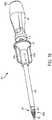
- FIG. 1illustrates one embodiment of a biceps tenodesis system that includes a sheath inserter tool 300, a sheath 100 coupled to a distal end of the sheath inserter tool 300, a driver tool 400, and an expander in the form of a screw 200 coupled to a distal end of the driver tool 400. While not shown in FIG. 1 , the system can also include a loader configured to removably mate to the driver tool 400 and the screw 200, as well as various other devices, such as bone preparation tools and measurement devices.
- the apparatus and methods described hereinmay have a number of advantages over existing techniques for preforming bicep tenodesis.
- the entire attachment preparation procedurecan be straightforward and requires a surgeon to take only a few quick steps to affix the implant structure including the sheath and the expander to the bone.
- a risk of damaging the tendon during rotation of the expander or any other technique requiring rotation of a component in direct contact with the tendonmay be avoided.
- a risk of causing trauma to the tendoncan be reduced and the time required to prepare and affix the tendon can be significantly reduced, which can facilitate the surgery and mitigate inconvenience to the patient.
- the described techniquescan help save operating room costs.
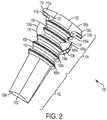
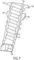
- FIG. 2illustrates the implantable sheath of FIG. 1 in more detail.
- the sheathis configured to seat a tendon therearound, and to receive an expander therein which is effective to cause the sheath expand into bone to anchor the tendon within a bone hole.
- the sheathcan be formed from any bio-compatible material, and it can optionally be bio-absorbable.
- the sheath 100has a generally elongate cylindrical shape, with a circular or ovular cross-sectional geometry.
- the sheath 100has a proximal end lOOp and a distal end 100d as shown in FIG. 2 .
- the sheath 100can be a split sheath, with a first sidewall 112a and a second sidewall 112b that are connected at the distal end 100d and that are separated by first and second elongates slots 114a, 114b extending therebetween.
- the elongate slots 114a, 114bcan extend from the proximal end lOOp and can terminate just proximal to the distal end 100d.
- the slots 114a, 114bare preferably shaped to seat a fork-member on the sheath inserter tool, as will be discussed in more detail below. In the illustrated embodiment, the slots 114a, 114b decrease in width in a proximal-to-distal direction.
- the distal end 100d of the sheath 100can be solid and closed, however an inner surface 116 can include a bore 120 formed therein that is configured to receive a guidewire 140 therein.
- the bore 120is preferably a blind bore that is threaded for mating with a threaded tip of the guidewire 140, however the bore can optionally extending all the way through the distal end.
- the elongate slots 114a, 114b formed in the sidewalls 112a, 112b of the sheath 100can allow for sheath expansion.
- the slots 114a, 114b between sidewalls 112a, 112b of the sheath 100preferably have a width that is greater than a width of the forks (discussed below) so that the sidewalls 112a, 112b can collapse inward toward the fork to allow the tendon and the sheath 100 to be pushed into the bone hole.
- the slots 114a, 114b in the resting statecan have a width that is greater than a width of the fork to allow the sidewalls 112a, 112b of the sheath 100 to move radially inward toward the fork by a first distance to a collapsed position.
- the sidewallscan also be configured to flex and move radially outward away from the resting position by a second distance to an expanded position.
- the sheath 100is configured to have a resting state in which the first and second distances are equal.
- Such a configurationcan be advantageous as the sidewalls 112a, 112b move from a middle resting position, rather than having the resting position be in the expanded position and having the sheath flex through both the first and second distances.
- the sidewalls 112a, 112bcan have a curvature that can be semi-circular.
- the sidewalls 112a, 112bcan collapse into an oval orientation.
- the sidewallscan expand to a circular orientation, which can help attain uniform compression all the way around the sheath 100.
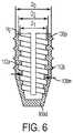
- the sheathcan be formed having a varied wall thickness. As shown in FIG. 6 , an outer diameter Do of the sheath can be substantially constant along the proximal portion and can taper distally inward along the distal portion to facilitate insertion.
- the inner lumen of the sheath 100can have both an inner minor diameter D1 and an inner major diameter D2.
- the inner major diameter D2 (and optionally the inner minor diameter D1) of the sheath 100can taper distally inward from the proximal end lOOp toward the distal end 100d, such that a thickness of the sidewalls 112a, 112b at a mid-portion 100m of the sheath 100 is greater than a thickness at the proximal end lOOp and the distal end 100d of the sheath.
- a mid-portion 100m of the sheath 100i.e., a portion of the sheath which is placed under the cortex, can expand to a diameter that is greater than a diameter of the sheath 100 at the proximal end lOOp, i.e., a portion of the sheath positioned within the cortex.
- the expansion of the mid-portion 100mthereby "anchors" the sheath 100 to prohibit retraction of the sheath 100 back through the bone hole opening.
- the sheath 100can also include a distal facing surface that is concave or saddled to seat the tendon thereon. This surface can be used to assist in the retention of the tendon during the insertion or dunking of the tendon and sheath 100 into the bone hole. This feature can be used in conjunction with or independent of other tendon retention features.
- the sheathcan include a convex proximal surface on each side wall 112a, 112b.
- the convex shapeprovides a rounded edge that can help avoid damage to any tissue in contact with the sheath.
- the sheath 100can also include various surface features formed thereon to facilitate engagement with the bone.
- the sheath 100can have surface features, such as ribs 106a, 106b, 106c, 106d, 106e, and each rib can be uni-planar so as to allow the sheath to be inserted into bone without the need to rotate the sheath.
- a distal portion 102 of the sheathcan be free of surface features. While ribs are shown, a person skilled in the art will appreciate that the sheath can include various bone-engaging surface features, such as threads, teeth, or other protrusions.
- the interior of the sheath 100can have a bore 120 formed in the solid distal tip of the sheath 100.
- the bore 120can be configured to receive the guidewire 140.
- the sheath 100can be pre-packaged on the guidewire 140 to enhance ease of use during the surgical procedure.
- the guidewire 140has a predetermined length that is sufficient to allow the guidewire to mate to the sheath and to extend all the way through and into the handle portion of each of the inserter and the driver.
- the guidewirecan also have a threaded distal tip 142 that is configured to mate with threads (not shown) formed in the bore 120 in the sheath 100.
- the bore 120is a blind bore such that the guidewire 140 does not protrude through the distal end 100d and is retained inside the sheath 100.
- the borecan extend entirely through the distal tip thereby allowing the guidewire 140 to protrude through the end of the sheath 100.
- the sheath 100can include features formed on the internal surface of the sidewalls 112a, 112b.
- the sidewalls 112a, 112bcan include threads 124 formed on the inner facing surfaces thereof for threadably mating with the screw 200.
- the threadscan extend along a portion of the interior of the sidewalls 112a, 112b or fully along the interior of the sidewalls 112a, 112b.
- Further internal featurescan include but are not limited to ridges, engagement members, or detents that could be used to assist the sheath 100 in pulling or engaging the screw 200 into its final position.
- the threads 124are shaped to match threads on the screw 200 when the sheath 100 is in the expanded state, not the resting state, as will be discussed in more detail below.
- the sheath 100can include anti-plunge tabs formed at the proximal end lOOp.
- FIGS. 2-7illustrate four anti-plunge tabs 110a, 110b, 110c, 110d that each have a generally rectangular configuration and that extend radially outward from a proximal end lOOp of the sheath 100 to prevent over insertion of the sheath 100 into the bone hole.
- first and second anti-plunge tabs 110a, 110bextend from opposed sides of the first sidewall 112a
- third and fourth anti-plunge tabs 110c, 110dextend from opposed sides of the second sidewall 112b.
- the anti-plunge tabs 110a, 110b, 110c, 110dare thus positioned adjacent to the slots 114a, 114b.
- the anti-plunge tabs 110preferably extend radially outward from the sheath 100 beyond a maximum outer dimension or diameter of the sheath so as to act as a stop that limits the insertion depth of the sheath into a bone hole.
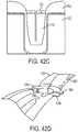
- FIGS. 42A-42Dillustrate another embodiment of a sheath 150 having anti-plunge tabs 156a, 156b, 156c, 156d formed at a top proximal end 150p.
- FIG. 42Ais a top view of a sheath having two pairs of anti-plunge tabs 156a, 156b, 156c, 156d that extend radially outward from opposed sides of the sheath 150.
- first and second tabs 156a, 156cextend from opposed sides of a first sidewall 158a
- third and fourth tabs 156b, 156dextend from opposed sides of a second sidewall 158b.
- the tabs 156a, 156b, 156c, 156dare positioned adjacent to slots 154a, 154b that separate the sidewalls 158a, 158b.
- the forked prongs of the inserter tooldiscussed in further detail below, can mate with the slots 154a, 154b to insert the sheath 150 into the bone hole.
- the top surface 152 of the sheath 150 or the proximal end 150pis configured to remain above the top surface of the bone 500. As shown in FIG.
- the anti-plunge tabs 156a, 156b, 156c, 156dwill abut the top surface of the bone, extending beyond the bone hole to limit the insertion depth of the sheath 150 into the bone hole.
- the tabs 156a-dare preferably oriented such that they are positioned on opposite sides of the tendon, i.e., in a direction perpendicular to the tendon.
- first and second tabs 156a, 156bcan be position proximate to the left side of the tendon 6001 and the third and fourth tabs 156c, 156d can be positioned proximate to the right side of the tendon 600r.
- the anti- plunge tabs 156a, 156b, 156c, 156dcan compress the tendon against the bone to facilitate anchoring of the tendon to the bone.
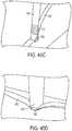
- FIGS. 43A-43Dillustrate another embodiment of a sheath 160 having an anti-plunge feature.
- the proximal end 160p of the sheath 160includes proximal flanges 162a, 162b extending radially outward from the proximal surface 168 of each sidewall.
- the first and second proximal flanges 162a, 162bcan extend from opposite sides beyond the diameter 160D of the sheath 160.
- the sheath 160can include opposed elongate slots 164a, 164b extending from the proximal end 160p toward the distal end 160d.
- the elongate slots 164a, 164bcan terminate just proximal to the solid distal tip 166 and can be configured to couple to an inserter tool, as will be discussed in further detail below.
- the first flange 162acan extend between the first and second elongate slots 164a, 164b, extending circumferentially around the perimeter of the proximal surface 168 of the first sidewall 170a.
- the second proximal flange 162bcan also extend between the first and second elongate slots 164a, 164b, extending circumferentially around the perimeter of the proximal surface 168 of the second sidewall 170b.
- the flanges 162a, 162bcan each have a generally semi-circular or oblong shape. As shown by FIG. 43C , when the sheath is implanted in a bone hole, the tendon 600 will be engaged between the proximal flanges 162a, 162b and the surface of the bone. The proximal flanges 162a, 162b can thus be positioned on the top surface of the tendon 600 covering the bone.
- the proximal flanges 162a, 162bcan be formed from a flexible material and can be configured to provide relief to the tendon by flexing. As shown in FIG.
- the outer edges 172b, 147b of the proximal flanges 162a, 162bcan flex upward away from the surface of the bone while the inner edges 172a, 174a of the proximal flanges 162a, 162b located proximate to the elongated slots 164a, 164b can flex downward toward the bone hole pressing the tendon 600 into place.
- the flanges 162a, 162bare oriented in-line with the tendon, such that the first flange 162a extends across the tendon along one side of the bone hole, i.e., the distal side, and the second flange 162b extends across the tendon along the opposite side of the bone hole, i.e., the proximal side.
- the sheath 100can further include cortical retaining tabs 108a, 108b positioned along the mid-section of the sheath 100, e.g., at a location just distal to the proximal end lOOp.
- the cortical retaining tabs 108a, 108bare preferably positioned about 2 mm from the proximal-most end such that the cortical retaining tabs 108a, 108b will be positioned just beyond cortical bone and within cancellous bone when the sheath 100 is implanted in a bone hole.
- the cortical retaining tabs 108a, 108bcan be sized to match a diameter of the bone hole.
- the cortical retaining tabs 108a, 108bcan have an outer diameter that is equal to or less than a maximum outer dimension or diameter of the sheath 100.
- the sheath 100includes four cortical retaining tabs 108a, 108b, 108c, 108d, with two on opposite sides of each sidewall 112a, 112b.
- the sheath 100can include any number of cortical retaining tabs 108a, 108b
- the sheath 100can also include anti-collapse tabs 128a, 128b, 128c, 128d integrally formed or positioned on the interior walls 126a, 126b for preventing collapse of the walls 126a, 126b beyond a predetermined position.
- an edge of each of the first and second sidewalls 112a, 112b, extending adjacent to the first and the second elongate slots 114a, 114b,define four anti-collapse tabs.
- the tabscan move toward one another, but they act as a stop to prevent the sidewalls 112a, 112b from fully collapsing.
- the tabs 128a, 128b, 128c, 128dcan thus allow the sidewalls to collapse toward one another when the sheath 100 and tendon are inserted into bone but prior to completion of the procedure and the insertion of the screw 200.
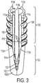
- the sheath 100is configured to receive a screw 200 therein that is effective to expand the sheath 100 to anchor the sheath 100 and ligament coupled thereto within a bone hole.
- the screw 200can have a generally cylindrical shape with a constant minor diameter D 1 along at least a proximal portion 200p, and preferably along a majority of the length, e.g., more than half of the total length.
- a distal portion 200d of the screw 200can taper distally inward to a reduced diameter at the distal-most end.
- the screw 200can have threads 202 formed there along and extending along the entire length to facilitate engagement with the sheath 100.
- the screw 200can be fully cannulated for allowing the screw 200 to be delivered over a guidewire 140, and the screw 200 can have a flat proximal facing surface 206 and a flat distal facing surface 208.
- the proximal surface 206 and the distal surface 208can have various shapes and the shape can be configured to conform to the sheath and/or the bone surface.
- the inner lumen 210can have a diameter that is sized to receive a guidewire. At least a proximal portion of the inner lumen 210 can be shaped to receive a driver tool.
- the proximal portion 200pcan have a hexagonal bore to receive a hexagonal drive tool.
- the screw 200can be inserted into the sheath 100 during use. Upon insertion into the sheath 100, the screw 200 can cause the sheath 100 to expand.
- the threads 202 on the screw 200have a height H t ( FIG. 8 ) that is less than a height H g ( FIG. 6 ) of the internal threads 124 formed in the sheath 100. This configuration will allow the minor diameter D 1 of the screw 200 to contact the inner minor diameter D1 ( FIG. 6 ) of the sheath 100 and thereby cause expansion of the sheath 100.
- the threads 202are not sized to cause expansion of the sheath 100, and rather than minor diameter of the screw 200 causes expansion.
- the screw 200can be shaped to cause the thicker mid-portion of the sheath 100 to expand radially outward by a distance that is greater than the proximal end lOOp and the distal end 100d of the sheath, such that the mid-portion 100m forms the largest diameter of the sheath 100 in the expanded state, as previously discussed with respect FIG. 7 .
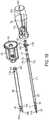
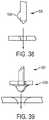
- FIG. 8Billustrates one embodiment of an expander 220 that is configured to be partially non-rotatably inserted into the sheath and then rotatably inserted into the sheath.
- the expander 220includes a proximal portion 220p having threads 222 formed thereon, and a distal portion 220d that is non-threaded and free of surface features.
- the length of the proximal and distal portions 220p, 220dcan vary, but in an exemplary embodiment each portion is about half of the entire length of the expander 220.
- the illustrated proximal portion 220phas a generally cylindrical shape with a constant minor diameter D 1 , and the distal portion 220d of the expander 220 tapers distally inward to a reduced diameter at the distal-most end.
- the expander 220can be fully cannulated for allowing the expander 220 to be delivered over a guidewire 140, and the expander 220 can have a flat proximal facing surface 226 and a flat distal facing surface 228.
- the non-threaded distal portion 220d of the expander 220can be non-rotatably advanced into the sheath 100. Once the distal portion 220d is fully disposed within the sheath 100, the expander 220 can then be rotated to thread the proximal portion 220p into the sheath.
- the sheathcan include corresponding threads along an entire inner surface thereof, or along on a proximal portion of the inner surface thereof, for mating with the threads 222 on the expander 220.
- FIG. 8Cillustrates another embodiment of an expander 240 that is configured to be non-rotatably advanced into a sheath.
- the expander 240has a generally cylindrical shape with a constant minor diameter D 1 along a proximal portion 240p and a convex belly along a mid-portion 240m to a distal portion 240d.
- the distal portion 240d of the expander 240is tapered distally inward to a reduced diameter at the distal-most end.
- the mid-portion 240m and the distal portion 240dcan be free of any surface features and can be relatively smooth.
- the proximal portion 240pcan include one or more ribs or flanges 242 formed thereon and extending circumferentially therearound.
- the proximal portion 240pincludes two ribs 242 formed thereon and spaced longitudinally apart.
- Each rib 242includes a flat proximal-facing surface 242p, and an outer sidewall having a proximal constant diameter portion 242c and a distal tapering portion 242t.
- the ribs 242have an outer diameter that is greater than the minor outer diameter of the expander 240.
- the expander 240can be fully cannulated for allowing the expander 240 to be delivered over a guidewire 140, and the expander 240 can have a flat proximal facing surface 246 and a flat distal facing surface 248. In use, the expander 240 can be non-rotatably advanced into the sheath 100. The ribs 242 on the proximal portion 240 can cause the sheath to expand outward thereby anchoring the sheath within the bone hole.
- inserter toolsare also provided for inserting the sheath 100 and/or screw 200 into a bone hole.
- the inserter toolcan also be used to perform various other functions in connection with insertion of the sheath into a bone hole.
- the anchor inserter toolcan be effective to initially measure a size of a tendon.
- Multiple inserter tools having different sizescan be provided, with the sizes corresponding to the appropriately sized sheath and screw to be used therewith.
- the inserter toolcan also be configured to insert or "plunge" a tendon into a pre-drilled bone hole, and to maintain the tendon within the bone hole while delivering a sheath 100 into the bone hole.
- the inserter toolcan further be configured to receive a guidewire 140 therein that is coupled to the sheath 100.
- the inserter toolcan be configured to fixedly engage the guidewire 140 to prevent movement thereof during plunging of the tendon and during delivery of the sheath 100, and it can be configured to selectively release the guidewire 140 once the sheath 100 is implanted to allow the tool to be removed from the guidewire 140, leaving the sheath 100 implanted with the guidewire 140 extending therefrom.
- FIGS. 10-17illustrate one exemplary embodiment of a sheath inserter tool 300 and various components and features thereof.
- the sheath inserter tool 300generally includes an outer component having a handle 302 with an outer shaft 306 extending therefrom, and an inner component that includes a trigger 304 that is slidably coupled to the handle 302 and an inner shaft 310 extending from the trigger 304 and through the outer shaft 306.
- the inner shaft 310includes features for interacting with the sheath.
- the sheath inserter tool 300can also include features disposed within the handle 302 for controlling movement of the inner and outer shafts 310, 306 relative to one another, as will be discussed in more detail below.
- the handle 302can have a variety of configurations, but in the illustrated embodiment the handle 302 on the outer component has a generally elongate cylindrical configuration to facilitate grasping thereof.
- the handle 302can have a bore extending therethrough from the distal end 302d and terminating just distal to the proximal-most end. In other embodiments, however, the bore can extend through the proximal end of the handle 302.
- the borecan be configured to receive various components for controlling movement of the inner and outer shafts relative to one another.
- a distal portion of the borecan receive the proximal end of the outer shaft 306 for mating the shaft to the handle.
- the handle 302can further include elongate longitudinal cut-outs 338a, 338b formed in opposite sidewalls thereof and in communication with the inner lumen.
- the cut-outs 338a, 338bcan allow the trigger 304 on the inner component to extend therethrough and to slidably move there along.
- the trigger 304can also have various configurations, but as shown the trigger 304 is generally T-shaped and includes distal facing finger-gripping surfaces 340a, 340b.
- the trigger 304extends laterally outward from opposed sides of the handle 302, through the cut-outs 338a, 338b, and thus allows a user to place the proximal end 300p of the handle 302 in their palm and to grasp the trigger 304 with two fingers to pull the trigger 304 proximally.
- the triggercan thus slide proximally and distally relative to the handle.
- the trigger 304can be fixedly mated to or integrally formed on the proximal end of the inner shaft 310. As a result, movement of the trigger 304 relative to the handle 302 moves the inner shaft 310 relative to the outer shaft 306.
- the handlecan include additional features for controlling movement of the inner and outer components relative to one another.
- the handle 302includes a primary biasing member 314 e.g., a spring, disposed therein and configured to apply a distal biasing force to the trigger 304.
- the primary biasing member 314thus pushes the trigger 304 and thus the inner shaft 310 distally.
- the biasing forcemust be overcome to cause compression of the primary biasing member 314.
- a first forcecan be applied to move the trigger 304 in a proximal direction along a first range of motion, i.e., a first distance, to cause at least partial compression of the primary biasing member 314.
- the trigger 304can also move further proximally along a second range of motion, i.e., a second distance, however the handle 302 can be configured to prevent proximal movement beyond the first range of motion unless a second force is applied to the trigger, 304 with the second force being greater than the first force.
- the second biasing member 318e.g., a spring can provide the second force for proximal movement beyond the first range of motion. As shown in FIG. 11A , the secondary biasing member 318 is located proximal to the primary biasing member 314.
- the handlecan also include a feature for engaging the guidewire mated to the sheath.
- a guidewire retainer or a guidewire grasper 316can be disposed between the primary and second biasing members 314, 318.
- the guidewire retainer 316can include a bore 342 formed therein that is configured to receive a proximal end of the guidewire 140 mated to the sheath 100.
- the bore 342is preferably sized to engage the guidewire 140 by compression fit to hold the guidewire 140 in a fixed position.
- the guidewire retainer 316can be formed from a compressible material to engage the guidewire. A person skilled in the art will appreciate, however, that other techniques can be used to engage the guidewire.
- the guidewire graspercan move axially within the handle and proximal movement to a certain position can cause the guidewire grasper to release the guidewire.
- the secondary biasing member 318can apply the distally-directed biasing force to the guidewire retainer 316 to prevent proximal movement of the guidewire retainer until the second force is applied to cause the retainer to move proximally and release the guidewire.
- the proximal end of secondary biasing member 318can define an abutment surface.
- the handle 302can include a proximal-most member, e.g., a handle plunge 320, that abuts the proximal-most inner surface of the handle 302, and that allows the secondary biasing member 318 to be compressed between it and the guidewire retainer 316.
- the primary biasing member 314compresses.
- the secondary biasing member 318applies a biasing force to the guidewire retainer 316 that is sufficient to prevent proximal movement of the guidewire retainer 316, and thus to resist movement of the trigger 304 beyond the first range of motion.
- a greater forcecan be applied to move the trigger 304 further proximally through the second range of motion.
- the greater forceneeds to be sufficient to overcome the biasing force of the secondary biasing member 318.
- proximal movement of the guidewire retainer 316will release the guidewire 140, as the mating connection between the sheath 100 and guidewire 140, and abutment of the sheath 100 against the distal end of the outer shaft 306, will prevent the guidewire 140 from moving proximally with the guidewire retainer 316.
- the sheath inserter tool 300can thus be removed, leaving the guidewire 140 behind.
- FIGS. 11B and 11Cillustrate one embodiment of a locking mechanism that could be located on the handle 302 and configured to engage a proximal portion of the inner shaft 310.
- the locking mechanismincludes a lock 914 which can be disposed at various locations on the handle 302.
- the lock 914is generally in the form of an elongate shaft having a cut-out formed therein.
- the cut-outincludes a longitudinally extending pin that is configured to be moved in and out of a hole in the proximal end of the inner shaft 310.
- the lock 914When the lock 914 is pushed toward one side of the handle 302 and the pin extends through a hole, the inner shaft is prevented from movement. Conversely, when the lock 914 is pushed toward the other side of the handle such that the pin is removed from the hole, the inner shaft is free to move. Accordingly, when in a locked position, the lock 914 prevents proximal movement of the actuator and locks the inner and outer shafts from moving longitudinally with respect to each other. When in the unlocked position, the actuator and the inner shaft 310 can move proximally relative to the handle 302 and outer shaft 306. A person skilled in the art will appreciate that a variety of other locking mechanisms known in the art can be used to lock the inner and outer components relative to one another.
- the inner shaft 310is coupled to and extends from the trigger 304 and can have a generally elongate cylindrical shape with a fork 308 on a distal end 300d thereof.
- the fork 308can function to both measure a tendon, and to facilitate insertion of the tendon and sheath 100 into a bone hole.
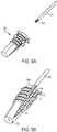
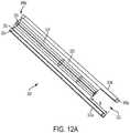
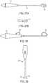
- FIG. 12Ais an enlarged transparent view of the fork 308, and
- FIG. 12Bis an end view of the fork 308.
- the fork 308includes first and second elongate prongs 324a, 324b that extending longitudinally along opposed sides of a cylindrical central portion 328.
- the elongate prongs 324a, 324bcan each have a generally square or rectangular cross-sectional shape, and the prongs 324a, 324b can be coupled to the cylindrical central portion 328 by connectors 326 extending longitudinally along the entire length of the distal end.
- the connectors 326can have a width Wc that is less than a width Wp of the prongs 324a, 324b.
- the central portion 328can include a guidewire bore 330 or channel extending therethrough and sized to slidably receive the guidewire 140 mated to the sheath 100.
- the pair of prongs 324a, 324bcan extending distally beyond the connectors 326 and the central portion 328 by a predetermined distance D to thereby define a u-shaped recess 322 between the pair of prongs 324a, 324b.
- the u-shaped recess 322can be configured to receive the sheath 100 therein, with the prongs 324a, 324b extending into the opposed sidewall cut-outs in the sheath 100.
- the u-shaped recess 322can include a coned shaped protrusion formed therein to provide support to the sheath 100.
- the protrusioncan have a cylindrical proximal portion with a tapering distal portion that decreases distally in diameter.
- FIGS. 12C and 12Dillustrate an embodiment of an inserter tool that is similar to inserter tool 300 and includes an outer shaft 306' and an inner shaft (not shown) with a fork 308' on the distal end thereof.
- the fork 308'has prongs 324' that are deformable and that can be configured to bow or flex outward into a generally convex configuration.
- the inner shaft and the fork 308'can configured to be locked relative to the outer shaft 306', and in use such a configuration can aid in dunking a sheath fully into a shallow bone hole, where the sheath length is less than the bone hole depth, but the overall length of the locked, extended retractable inserter forks are longer than the bone hole depth.
- FIG. 12Cillustrates prongs 324' having a generally linear configuration. Once inserted through a bone hole H and into bone B, the locked, extended, retractable inserter fork 308' can have a length that allows the prongs 324' to abut against an opposite inner surface of the bone B. The prongs 324' can thus deform and bow outward, as shown in FIG. 12D . The outward expansion of the prongs 324' will occur below the near cortex, against the far interior cortical wall, thus aiding in anchoring the sheath (not shown) fully flush within the bone hole.
- FIG. 13illustrates the fork 308 extending from the distal end of the outer shaft 306.
- the outer shaft 306has an outer diameter D b that is greater than a maximum width Wp of the prongs 324a, 324b. Such a configuration will allow the sheath proximal end to abut the outer shaft 306 distal end when the fork 308 is inserted into the sheath 100.
- the inner shaftcan move axially relative to the outer shaft to retract and extend the fork into and from the outer shaft 306.
- the barrel distal-facing end surface 306dcan include a cut-out 336 formed therein that is shaped to match the shape of the fork 308 on the inner shaft 310.
- the cut-out 336thus allows the fork 308 to be fully retracted into the outer shaft 306, as shown in FIG. 14A and also allows the guidewire 140 to be received therein.
- the guidewire 140 and the sheath 100 mated theretocan be slid in a proximal direction into the distal end of the outer shaft 306.
- the guidewire 140can be moved proximally until the proximal end of the guidewire 140 is received within and in engagement with the guidewire retainer 316 in the handle 302.
- the sheathwill abut the distal end of the barrel to prevent further proximal movement of the sheath and the guidewire.
- the outer shaft 306"can include cut-outs or recesses 307" that are configured to seat the anti-plunge tabs on the proximal end of the sheath 100.
- the recesses 307"can be formed on opposite sides of the cut-out 336" for allowing the anti-plunge tabs on the sheath to sit without the distal end of the outer shaft 306".
- the outer shaft 306"can also optionally include features to facilitate percutaneous insertion of the outer shaft 306" through tissue.
- a concavity 308"(only one is shown) can be formed in opposite sides of the outer shaft 306" adjacent to the distal end to reduce the profile of the outer shaft and therefore facilitate insertion of the distal end through tissue.
- the concavity 308" in each sidewallcan also seat the tendon, providing relief for the tendon during advancement of the sheath into the bone hole.
- FIG. 15illustrates the sheath 100 loaded onto the distal end of the inserter.
- the outer shaft 306can have a diameter 306d that is greater than major diameter of the ribs on the sheath 100, and that is greater than a maximum width between the prongs 324a, 324b on the fork of the inserter tool.
- the outer diameter of the outer shaft 306can be dimensioned with respect to the width of the anti-plunge tabs 110a, 110b, 110c, 110d so that the distal end of the outer shaft 306d can thus operate in conjunction with the anti-plunge tabs 110a, 110b, 110c, 110d on the sheath 100 to prevent over insertion of the sheath 100 into bone, as both the outer shaft 306 and the anti-plunge tabs 110a, 110b, 110c, 110d can abut the bone surface when the sheath is inserted into an appropriately sized bone hole.
- the bone holeis preferably reamed using a drill that is sized to correspond to the selected size of the sheath inserter tool 300.
- the bone holecan be reamed to have a diameter that is slightly greater than the diameter of the ribs 106a, 106b, 106c, 106d, 106e on the sheath 100, but less than the maximum width of the anti-plunge tabs 110a, 110b, 110c, 110d on the sheath 100.
- the distal end of the outer shaft 306will also prevent proximal movement of the sheath 100 relative to the inserter tool, thereby maintaining the sheath and the guidewire attached thereto in a fixed position, as will be discussed below.
- the sheath insertercan be provided in multiple sizes that correspond to the size of the tendon and the anchor.
- FIGS. 16A and 16Billustrate the sheath inserter of FIGS. 10 and 11A , with FIG. 16A showing a size small sheath inserter tool 300s and FIG. 16B showing a size large sheath inserter tool 3001, as is evident from the increased size of the outer shaft 3061 and the fork 3081.
- FIGS. 17A-17Cillustrate use of the inserter.
- the fork 308is in the initial resting position, extending from the outer shaft 306.
- FIG. 17Athe fork 308 is in the initial resting position, extending from the outer shaft 306.
- FIG. 17Bthe fork 308 is shown fully retracted into the outer shaft 306, with the trigger 304 moved proximally through the first range of motion.
- FIG. 17Cshows full retraction of the fork 308 inside the outer shaft 306, and illustrate that further proximal movement through the second range of motion can release the guidewire 140.
- the sheath inserter tool 300is preferably inserted percutaneously through tissue with the fork 308 in the fully retracted position.
- FIGS. 18 and 19illustrate one exemplary embodiment of a driver tool 400.
- the driver tool 400generally includes a driver handle 402 having an inner shaft 410 extending distally therefrom, and a knob 404 having an outer shaft 406 extending distally therefrom.
- the inner shaft 410extends through the knob 404 and the outer shaft 406, with the driver handle 402 positioned proximal of the knob 404.
- An anti-rotation fork 408is located on a distal end of the outer shaft 406 and can be configured to prevent rotation of the sheath 100 as the inner shaft 410 is used to thread the screw 200 into the sheath 100.
- the inner shaft 410can include a guidewire channel 430 extending therethrough for allowing the guidewire 140 mated to the sheath 100 to be received therein.
- the driver handle 402 and inner shaft 410can have a variety of configurations.
- the driver handle 402has a generally elongate cylindrical configuration to facilitate grasping thereof.
- a bore 403can extend through the handle and can include a proximal portion 403a that is sized to receive the guidewire and an enlarged distal portion 403b for receiving a proximal end of the inner shaft 410.
- the inner shaft 410is preferably fixedly mated to or integrally formed with the driver handle 402. As shown in FIG. 19 , the proximal end 410p of the inner shaft 410 includes mating screws 418a, 418b, 418c for securely and fixedly mating the inner shaft 410 to the driver handle 402. However other techniques, such as various mechanical engagement mechanisms, welding, adhesives, etc., can be used.
- the inner shaft 410can have a general elongate cylindrical configuration with a distal end 410d that is configured to mate to an expander, such as screw 200.
- the distal end 410dcan include a drive tip 432 formed thereon for engaging the screw 200.
- the drive tip 432has a hexagonal configuration for extending into a corresponding hexagonal drive socket formed in the screw to thereby allow the inner shaft 410 to rotate the screw 200.
- other alternative shapes that non-rotatably matecan be used.
- the inner shaft 410can further include a guidewire channel 430 extending therethrough for allowing the screw 200 and the inner shaft 410 to be slidably advanced over the guidewire 140 mated to the sheath 100, as will be discussed further below.
- the knob 404 and outer shaft 406can also have a variety of configurations, but as shown in FIGS. 18 and 19 , the knob 404 is generally cylindrical with first and second opposed alignment indicators or tabs 414a, 414b.
- the tabs 414a, 414bcan be aligned with prongs 424a, 424b on the anti-rotation fork 408, discussed below, to indicate the position of the prongs 424a, 424b to a user grasping the knob 404.
- the outer shaft 406can have a generally elongate cylindrical configuration, with a proximal end 406p that is received within an inner lumen that extends through the knob 404.
- the proximal end 406p of the outer shaft 406can be fixedly mated to the knob 404 using mating screws 412a, 412b, or other mating techniques.
- the outer shaft 406 and the knob 404can be slidably disposed over the inner shaft 410.
- the outer shaft 406 and the inner shaft 410are freely rotatably relative to one another, however longitudinal movement of the inner shaft 410 and the outer shaft 406 relative to one another is limited.
- the inner shaft 410can include stop pins 416a, 416b disposed thereon and protruding radially outward from opposite sides thereof. The stop pins 416a, 416b can be located just distal of the proximal end of the inner shaft 410.
- the stop pins 416a, 416bcan be positioned within the inner lumen 434 extending through the knob 404.
- the stops pins 416a, 416b and the knob 404can be configured such that the stop pins 416a, 416b only allow the knob 404 to slide proximally and distally a predetermined distance.
- the knob 404can include a reduced diameter region 428d adjacent the distal end that limits distal movement of the pins 416a, 416b, and a reduced diameter region 428p adjacent the proximal end that limits proximal movement of the pins.
- the proximal reduced diameter region 428pcan, however, include opposed pin slots 420a, 420b formed therein for allowing the pins 416a, 416b to pass therethrough when properly aligned with the slots 420a, 420b.
- Such a configurationallows the knob 404 and outer shaft 406 to be removed from the inner shaft 410 and driver handle 402, e.g., for cleaning.
- the distal end 406d of the outer shaft 406can include an anti-rotation fork 408 having first and second opposed distal prongs 424a, 424b extending distally from opposite sides of the outer shaft 406.
- the prongs 424a, 424bcan be configured to extend into the sidewalls slots in the sheath 100 to prevent rotation of the sheath 100 when the inner shaft 410 is rotated to drive the screw 200 into the sheath 100.
- FIGS. 21-23illustrate the prongs 424a, 424b in more detail. As shown, each prong has a generally triangular configuration and extends from a semi-cylindrical sidewall. The prongs can thus extend into the slots in the sheath 100, while the sidewall abuts against a proximal end surface of the sheath. Such a configuration will limit insertion of the driver tool 400 into the sheath 100.
- the outer shaft 406can also include features to facilitate viewing of the screw 200 coupled to the driver tool 400 and disposed within the outer shaft 406.
- the outer shaft 406can include one or more viewing windows or visibility windows 426 formed therein at a location adjacent to the distal end.
- the viewing windows 426 in the illustrated embodimentare in the form of elongate oval cut-outs formed through both sidewalls on opposite sides of the shaft and in alignment with the prongs 424a, 424b.
- the viewing windowscan be at various locations and can have various configurations to allow for visibility into the inner lumen.
- the outer shaft 406can also include tendon cut-outs 422a, 422b positioned on opposed sides of the outer shaft 406 and offset from the prongs 424a, 424b and visibility windows 426 by about 90 degrees.
- the tendon cut-outs 422a, 422bcan allow a tendon wrapped around the sheath 100 to protrude up into the cut-outs if needed.
- the screwcan be mated to the drive tip 432 on the inner shaft 410.
- the anti-rotation fork 408can be advanced over the screw 200 such that the anti-rotation fork 408 can extend into the slots in the sheath 100 to prevent rotation of the sheath during insertion of the screw into the sheath.
- the driver handle 402can be rotated relative to the knob 404 to thereby rotate the inner shaft 410 within the outer shaft 406.
- the inner shaft 410will thus rotate and drive the screw 200 into the sheath 100 while the outer shaft 406 holds the sheath 100 stationary and prevents it from rotating.
- Such a configurationis particularly advantageous as it prevents rotation of the tendon, since the tendon is positioned around the sheath.
- the anti-rotation fork 408can also be effective to prevent the sheath 100 from backing-out of the bone tunnel during insertion of the screw 200. Without the anti-rotation fork 408, the tendon can have a tendency to pull the sheath out of the bone hole. The anti-rotation fork 408 can thus be used to push the sheath into the bone hole until the anti-plunge tabs on the sheath rest against with the bone surface.
- the driveralso includes markings to facilitate use.
- markingscan be formed on the inner and/or outer shafts to indicate the position of the outer shaft relative to the inner shaft, thereby indicating the position of the screw relative to the sheath.
- a first markingin the form of a laser etched band 407, extends around the distal end portion of the outer shaft 406 on the inserter tool, as shown in FIG. 21 .
- a second markingin the form of a laser etched band 411, extends around the distal end portion of the inner shaft 410, as shown in FIG. 19 .
- Alignment of the band 411 on the inner shaft with the band 407 on the outer shaftwill indicate that the expander screw is fully driven into the sheath.
- a pair of markingscan also or alternatively be formed on the proximal portion of the device.
- the inner shaft 410can include a pair of markings, in the form of laser etched bands 413, 415, that are located distal of the driver handle 402.
- the distal band 415will align with the proximal end surface of the knob 404 when the device is in the initial configuration, prior to driving the expander screw into the sheath.
- the distal band 413when aligned with the proximal end surface of the knob 404, will indicate that the expander screw is fully driven into the sheath.
- the driver tool 400can also optionally be used with a screw loader cartridge 500 to facilitate loading of the screw 200 onto the guidewire for delivering the screw into the sheath.
- FIG. 25illustrates one embodiment of a screw loader cartridge 500.
- the screw loader cartridge 500can be formed from various materials, such as metal or a molded plastic, and can have various shapes and configurations.
- the screw loader cartridge 500includes a proximal portion 500p with wings 502 formed thereon to facilitate grasping, and a distal portion 500d that is in the shape of a funnel 504 that is cut almost in half.
- the screw loader cartridge 500can thus have a generally planer side as shown.
- An elongate channel 506can be formed in the proximal portion 500p and it can extend toward the funnel 504 and can communicate with the funnel 504.
- the channel 506can be shaped to seat the screw 200 and optionally a distal portion of the driver tool 400, including the anti-rotation fork 408.
- the screw loader cartridge 500can seat the screw 200 and the anti-rotation fork 408 on the outer shaft such that the outer shaft is in its proximal-most position and prevented from further movement.
- Such a configurationcan help prevent rotation and axial translation of the driver tool inner and outer shafts when the loader and expander are mated thereto. This can be particularly desirable for packaging and preventing movement during shipping until use of the device.
- the screw 200can be held within the channel 506 by press fit or using other techniques known in the art.
- the guidewire channel(not shown) extending through the screw 200 can align with the opening of the funnel 504. In use, the guidewire can thus be inserted into the funnel 504, which will thereby guide the guidewire into the screw 200 for ease of insertion.
- FIGS. 26A-26Dillustrate use of the screw loader cartridge 500 for loading the screw onto the guidewire.
- FIG. 26Ais a side view of the screw loader cartridge 500, showing the screw 200 seated therein.
- the screw 200can simply be side-loaded into the channel 506.
- the funnel 504can receive and guide the guidewire 140 into the screw 200.
- the tabs 502 on the screw loader cartridge 500can be grasped and used to pull back on the screw loader cartridge 500 and disengage the screw loader cartridge 500 from the screw 200.
- the loadercan be discarded or optionally sterilized and reused.
- the componentscan optionally be shipped with the screw and loader pre-loaded onto the screw driver tool.
- FIGS. 27A-31include various embodiments for measuring the size of a tendon.
- the tendon sizer 710generally includes a handle 711 with a shaft 712 extending distally therefrom.
- a distal end of the shaft 712includes a sizer 713 having various cut-outs formed therein, each with a different size.
- a tendoncan be positioned within each cut-out until the size of the tendon matches the size of the cut-out.
- FIG. 27Billustrates a similar sizer 714, however the cut-out are aligned axially along the distal end, rather than positioned in a circular orientation as in the FIG. 27A embodiment.
- FIG. 28illustrates another embodiment of a tendon measuring device 720 that is similar to the device of FIG. 27A , but that includes a retractable wire loop 723 on a distal end thereof.
- a knob 724 on the handle 721can be slid proximally and distally to adjust a size of the loop 723.
- a tendoncan thus be positioned within the loop, and once adjusted to match the size of the tendon, the device can indicate the size to the user.
- FIGS. 29-31illustrate another embodiment of a tendon measuring device 730 that is similar to the device of FIG. 28 , but rather than an adjustable wire loop, device 730 includes an adjustable arm 733 that moves with respect to a stationary arm 734 to allow a size of a tendon to be measured.
- FIGS. 32-33Cillustrate various other devices for determining tendon size and/or for reaming a bone hole.
- a combination guidewire and bone reamer tool 760is provided.
- the devicehas a shaft with a distal end in the form of a reamer for reaming a bone hole, and a guidewire extends through the shaft.
- FIGS. 33A-33Cillustrate a device that is similar to the device of FIG. 32 , but that is in the form of a combination reamer and sizer tool 770.
- the reamerincludes a forked sizer 772 slidably disposed therein.
- the forkexpands in size for measuring tendons of differing size.
- the devicecan include markings or other features on a proximal end (not shown) for indicating the size of the measured tendon and/or the size of the implant and tool set to be used with the tendon.
- a tendon measuring device 780having a tamp 780 for measuring a tendon size.
- the device 780includes a handle 781 having an elongate shaft 782 extending distally therefrom with the tamp 780 formed on the distal end thereof.
- the tamp 780can be inserted and pressed down on the bicep tendon in the ream and dunk location, as shown in FIGS. 34B-C . If the tendon compresses to a width of the tamp 780, the tendon requires a small scheme tool and implant set. If the tendon compresses and it is larger than the tamp 780, as shown in FIG. 34C , then it requires a large scheme tool and implant set.
- FIGS. 35-37illustrate another embodiment of a device 810 that can be used to prepare a bone hole.
- the device 810includes a generally L-shaped handle 812 having first and second shafts 814, 816 extending from opposed ends thereof.
- Each shaftcan include a bone hole cutter 814a, 816a formed on a distal end thereof.
- each cuttercan have a generally triangular configuration with truncated corners.
- One of the cutters, e.g., cutter 814acan have a first size and the other cutter, e.g., 816a can have a second size that differs from the first size.
- the cutterscan be provided in small and large sizes that correspond to small and large implant and tool sizes. The user can thus select the shaft and cutter having an appropriate size.
- the cutterscan have a variety of configurations.
- FIGS. 38-39illustrate additional cutter tip configurations for forming a bone hole having a desired shape.
- the cutter device 824includes a tip having a protrusion 824b extending from a side thereof for forming a notch in a proximal end of a bone hole.
- the devicecan optionally include two protrusions for forming two notches.
- the cutter 826b on the device 826has a configuration that forms a rounded edge at the top of the bone hole.
- FIGS. 40A-40Eillustrate one exemplary method for performing a biceps tenodesis surgery. While the method is described in connection with the system of FIG. 1 , a person skilled in the art will appreciate that the method can be performed using various anchors and tools, and that is can be performed for anchoring any tissue to any bone.
- a biceps tendonis retrieved, e.g., using suture, and a size of the tendon needs to be determined to allow a surgeon to select an appropriately sized implant and tools.
- Thiscan be achieved using the sheath inserter tool 300.
- the sheath inserter tool 300can be passed through tissue and positioned adjacent to the tendon and the implant site. As shown in FIG. 40A , the fork on the sheath inserter tool 300 can be manipulated to position the tendon 600 within the fork.
- the smallest toolis preferably used first and the tendon is positioned between the forks on the distal end. If the tendon fits, then the implant (sheath and screw) that has a size corresponding to the size of the sheath inserter tool is used. If the tendon is too large and does not fit between the prongs on the fork, the next size inserter tool can be used to again measure the tendon.
- a kitis provided having a small and a large sheath inserter, a small and a large implant (sheath and screw), and a small and large screw driver and loader. After properly sizing the tendon, the proper size reamer can be used to ream a bore in the bone, e.g., the humorous.
- a dual or triple ended toolcan be used that will break the edge of the bone opening with a quarter turn back and forth.
- the tool of FIGS. 35-36can be inserted percutaneously, and the appropriately sized tip can be selected, inserted into the bone hole, and rotated by hand to form a bone hole opening as shown in FIG. 37 .
- the device of FIG. 38 or FIG. 39can be used to create an angled surface within the bone hole. The angled surface can provide an alternate means of bone hole preparation that can mitigate the potential for the tendon to rip or tear on a sharp edge of the bone.
- the tendoncan be plunged into the bone hole using the appropriately sized inserter tool.
- the sheath and guidewirecan be loaded onto the inserter tool prior to plunging the tendon.
- the guidewire 140can be threaded into the inner bore in the sheath 100, which can be loaded into the distal end of the sheath inserter tool 300. This can be achieved by advancing the proximal end of the guidewire 140 into the distal end of the sheath inserter tool 300, and moving the guidewire 140 proximally until the guidewire 140 is press-fit into the guidewire retainer in the handle.
- the guidewire and sheath, or the guidewire, sheath, and inserter toolcan optionally be pre-packaged together in a mated configuration.
- FIGS. 40C-40Eillustrates various steps of inserting the sheath 100 and tendon 600 into the bone hole 602.
- the fork 308can be retracted by pulling proximally on the trigger through the first range of motion to allow for percutaneous insertion through the skin.
- the tip of the sheathcan serve as an obturator to pass the sheath and inserter tool through tissue. Once passed through tissue, the operator can release the trigger to allow the fork 308 to extend distally out of the outer shaft.
- the fork 308can be position around the tendon 600.
- a suturecan be used to tension the tendon, and the forks can be positioned proximal or distal to the hole with the tendon therebetween. The sheath will thus rest against the tendon.
- the fork 308, with the tendon therebetween,can then be slid toward the hole 602 and dunked into hole 602, as shown in FIG. 40C .
- the bone hole diametercan be sized to allow the fork 308 and the sheath to be easily inserted thereon. Some resistance may be encounter due to the tendon being wrapped around the sheath. Since the outer shaft of the sheath inserter tool 300 is oversized compared to the tunnel 602, the outer shaft will be prevented from entering into the bone hole 602. If resistance is encountered, the proximal end of the inserter tool can be tapped with a mallet.
- the cortical boneis typically only 1 mm to 2 mm thick.
- the goalis to tap the cortical retaining tabs into the hole until the anti-plunge tabs on the sheath 100 abut the bone surface such that over insertion of the sheath into the hole is prevented.
- the cortical retaining tabsare preferably sized so as to not cut through the bone when inserted therethrough.
- the fork 308can continue to straddle the tendon 600 all the way into bone 602.
- the sheath 100is fully inserted, the anti-plunge tabs and the distal end of the outer shaft will rest against the bone, as shown in FIG. 40D , and the cortical retaining tabs will extend below the cortical bone.
- the sheath inserter tool 300can be removed by pulling the trigger through the first range of motion to retract the fork, and further proximally through second range of motion to thereby release the guidewire 140 from the handle.
- the sheath inserter tool 300can then be slid off of the guidewire 140, leaving the sheath 100 in the bone hole 602 with the guidewire 140 extending therefrom, as shown in FIG. 40E .
- the screw 200can be driven into the sheath 100 using the driver tool 400.
- the screw 200can be loaded onto the driver tool 400 using the loader cartridge, or as indicated above the screw, loader, and driver can be pre-packaged in a fully assembly configuration.
- the loader tabhas a funneled distal tip to assist in positioning the guidewire into the screw 200.
- the funnelcan thus be advanced over the guidewire that is attached to the implanted sheath.
- the funnelwill thereby guide the guidewire into the screw, which can be slid a distance down the guidewire.
- the screw drivercan be advanced over the guidewire in conjunction with the screw.
- the loadercan then be removed, and the driver tool 400 can be used to advance the screw 200 into the sheath 100, as shown in FIGS. 41A-41C .
- the prongs on the outer shaft of the driver tool 400will extend into the slots in the sheath 100, as shown in FIG. 41D .
- the driver tool 400can hold the sheath 100 within the bone hole 602, preventing back out during screw 200 insertion.
- the viewing windows opposite one another and aligned with the tinescan facilitate viewing of the screw, and the side cut-outs offset from the viewing windows can receive the tendon so as to allow outer shaft to rest against sheath, as shown in FIG. 41D .
- the outer shaftcould be formed from a transparent material to allow viewing therethrough.
- the shaftcan have two laser lines, one on the inner shaft the other one on the outer shaft. When they are aligned, the screw 200 will be fully inserted.
- the proximal end of inner shaftcan also have a line that will align with the knob on the outer shaft to indicate full insertion of the screw 200 into the sheath 100.
- the linecan be particularly useful when the procedure is done without a scope (e.g., sub-pec during mini-open procedure).
- the screw 200When the screw 200 is fully inserted into the sheath 100, the screw will cause the sheath to expand radially outward to engage the tendon between the sheath and the bone hole, and to thereby anchor the sheath and tendon within the bone hole.
- the ribs on the outer surface of the sheathcan engage bone to prevent back-out.
- the expanded mid-portion of the sheath, as well as the cortical retainer tabs,can also help retain the sheath within the bone hole.
- the driver tool 400can be slid off of the guidewire 140.
- the guidewire 140can be removed, e.g., by bending the proximal end and turning the guidewire 140, to unthread it from the sheath 100.
- biceps tenodesis methods and devices disclosed hereincan be used in a variety of surgical procedures to trauma or damage to a tendon being attached to a bone via a bone hole.
- the present inventionalso has application in conventional joint repair surgeries.
- the devices disclosed hereincan be designed to be disposed of after a single use, or they can be designed to be used multiple times. In either case, however, the device can be reconditioned for reuse after at least one use. Reconditioning can include any combination of the steps of disassembly of the device, followed by cleaning or replacement of particular pieces, and subsequent reassembly. In particular, the device can be disassembled, and any number of the particular pieces or parts of the device can be selectively replaced or removed in any combination. Upon cleaning and/or replacement of particular parts, the device can be reassembled for subsequent use either at a reconditioning facility, or by a surgical team immediately prior to a surgical procedure.
- reconditioning of a devicecan utilize a variety of techniques for disassembly, cleaning/replacement, and reassembly. Use of such techniques, and the resulting reconditioned device, are all within the scope of the present application.
- the invention described hereinwill be processed before surgery.
- a new or used instrumentis obtained and if necessary cleaned.
- the instrumentcan then be sterilized.
- the instrumentis placed in a closed and sealed container, such as a plastic or TYVEK bag.
- the container and instrumentare then placed in a field of radiation that can penetrate the container, such as gamma radiation, x-rays, or high-energy electrons.
- the radiationkills bacteria on the instrument and in the container.
- the sterilized instrumentcan then be stored in the sterile container.
- the sealed containerkeeps the instrument sterile until it is opened in the medical facility.
- deviceis sterilized. This can be done by any number of ways known to those skilled in the art including beta or gamma radiation, ethylene oxide, steam.
Landscapes
- Health & Medical Sciences (AREA)
- Life Sciences & Earth Sciences (AREA)
- Veterinary Medicine (AREA)
- Public Health (AREA)
- Rheumatology (AREA)
- General Health & Medical Sciences (AREA)
- Animal Behavior & Ethology (AREA)
- Engineering & Computer Science (AREA)
- Biomedical Technology (AREA)
- Heart & Thoracic Surgery (AREA)
- Oral & Maxillofacial Surgery (AREA)
- Vascular Medicine (AREA)
- Transplantation (AREA)
- Cardiology (AREA)
- Rehabilitation Therapy (AREA)
- Orthopedic Medicine & Surgery (AREA)
- Surgery (AREA)
- Nuclear Medicine, Radiotherapy & Molecular Imaging (AREA)
- Medical Informatics (AREA)
- Molecular Biology (AREA)
- Surgical Instruments (AREA)
- Prostheses (AREA)
Description
- Surgical devices are provided for anchoring tissue to bone, and more particularly surgical implants and delivery tools are provided for securing a biceps tendon to the humerus.
- Disorders of the long head of the biceps tendon are a common source of shoulder pain and may occur in association with other diagnoses such as rotator cuff tears, superior labrum anterior posterior tears, impingement syndrome and capsular injuries, or may be present as an isolated source of shoulder pain. The treatment options for disorders of the long head of the biceps (LHB) continue to evolve and can include LHB tenodesis. In a tenodesis procedure, a suture is passed through the base of the LHB to locate the LHB in the subacromial space and to provide proximal control during the dissection. Once the suture is placed, the LHB is cut near the glenoid attachment. A sizer can be used to measure the tendon size and to thereby determine the appropriately sized bone screw. Once the screw is selected, a bone hole is drilled and a tendon fork is then used to push the tendon down into the bone hole. A bone screw is then delivered into the bone hole to anchor the tendon within the bone hole.
- While current procedures can provide an effective means for anchoring a tendon to bone, they can suffer from several drawbacks. For example, current procedures require the use of numerous tools, which can lead to a prolonged procedure and increased costs. The use of a screw can also increase the risk of damage to the tendon, as rotation of the screw into the bone hole can tear or sever through the tendon. Moreover, it can be difficult to maintain the desired tension on the tendon while the screw is being implanted, as the tendon can become misaligned and or can slip during insertion of the screw. Any tension applied to the tendon during insertion of the anchor can also cause the anchor to back-out of the bone hole.
- Accordingly, there remains a need for improved methods and devices for anchoring tissue to bone, and in particular for performing a biceps tenodesis.
WO 01/30253 A1 - Various implants, tools and methods are described for attaching a tendon to bone. The invention is defined by claims 1 and 6. In one embodiment that is not recited in the claims, an anchor assembly for anchoring a tendon to bone is provided and includes a sheath having a substantially solid distal end with at least two sidewalls extending proximally therefrom and separated by at least first and second slots. The sidewalls can have threads formed on an internal surface thereof and the sidewalls can define an inner lumen therebetween. The solid distal end of the sheath can have a mating feature. The anchor assembly can further include a guidewire having a distal tip configured to releasably mate with the mating feature in the sheath. In one embodiment, the mating feature can be a threaded bore formed in the sheath and the distal tip on the guidewire can be threaded for threadably mating with the threaded bore. The guidewire can extend proximally from the sheath when mated thereto. The anchor assembly can further include an expander that can have a generally elongate cylindrical configuration such that the expander is configured to be received within the inner lumen of the sheath. In one embodiment, the expander can have threads formed on an external surface thereof that can threadably mate with the threads formed on the internal surface of the at least two sidewalls. The expander can further include a lumen extending therethrough to receive the guidewire.
- In some embodiments, the sheath of anchor assembly can include at least one anti-collapse tab formed on at least one of the sidewalls adjacent to one of the slots. The at least one tab can be configured to limit movement of the sidewalls toward one another. In some embodiments, the sidewalls can have an increased thickness at a mid-portion thereof as compared to proximal and distal portions thereof. In other embodiments, the sidewalls can include ribs extending radially therearound. For example, the ribs on a first sidewall of the anchor can be angled distally and the ribs on a second opposite sidewall of the anchor can be angled proximally
- The sheath can also include at least one anti-plunge tab extending radially outward from a proximal-most end thereof. The anti-plunge tab can be configured to limit an insertion depth of the sheath into a bone hole. The sheath can also at least one retaining tab extending radially outward from the sheath at a predetermined distance from the anti-plunge tab. The distance can be configured such that the anti-plunge tab can be positioned on a proximal surface of cortical bone and the retaining tab can be positioned on a distal surface of the cortical bone. In one exemplary embodiment, the distance can be greater than about 0.5 mm.
- In some embodiments, the anchor assembly can include a sheath that can have a concave distal-facing end for seating a tendon. In some embodiments, the anchor assembly can include a sheath that can have a convex proximal facing end.
- In other aspects, the first and second slots can each have a proximal portion, a distal portion, and a transition region extending between the proximal and distal portions. The proximal and distal portions can each have a constant width, and the transition region can have a width that tapers inward in a distal direction. In an exemplary embodiment, a length of transition region can be substantially equally to a width of the proximal portion.
- In another embodiment, a method, which is not part of the claimed invention, for anchoring a tendon to bone is provided. The method can include positioning a distal end of a sheath over a tendon extending across a bone hole. The sheath can have a guidewire mated thereto and extending proximally therefrom. The sheath with the guidewire mated thereto can be advanced into the bone hole to cause the tendon to advance into the bone hole and extend between the sheath and the bone hole. A cannulated expander can be advanced along the guidewire and into the sheath to cause the sheath to expand outward to anchor the tendon within the bone hole.
- The method can include advancing the sheath into the bone hole using an inserter tool having the guide extending therethrough. The method can further include, after advancing the sheath, manipulating the inserter tool to release the guidewire from a guidewire grasper in the inserter tool, and removing the inserter tool from the guidewire. In another embodiment that is not claimed, when the expander is fully inserted into the sheath, the expander and the sheath can be in full circumferential contact along a majority of a length thereof. In another embodiment that is not claimed, the expander can be non-rotatably advanced into the sheath, or alternatively a distal portion of the expander can be non-rotatably advanced into the sheath, and a proximal portion of the expander can be rotatably threaded into the sheath.
- In other aspects that are not claimed, the method can include advancing the expander along the guidewire using a driver tool. The driver tool can include an outer shaft having opposed prongs on a distal end thereof that are positioned within opposed slots formed in the sheath. The driver tool can further include an inner shaft extending through the outer shaft and engaged with the expander. The inner shaft can be rotated to advance the expander into the sheath while the prongs on the outer shaft hold the sheath substantially stationary. The driver tool can be removed from the guidewire and the sheath leaving the sheath and the expander implanted in bone.
- In another embodiment, which is not recited in the claims, an anchor assembly for anchoring a tendon to bone is provided and includes a sheath and a threaded expander. The sheath can have a body with at least two sidewalls extending proximally therefrom. The sidewalls can be separated by at least first and second slots, and the sidewalls can define an inner lumen therebetween. The sidewalls can further include threads formed on an internal surface thereof. The threaded expander can be configured to be received between the at least two sidewalls and to threadably mate with the threads formed on the internal surface of the sidewalls. The sheath and the threaded expander can be configured such that, when the expander is fully threaded into the sheath, a mid-portion of the sidewall expands outward by a distance that is greater than a distance that proximal and distal portions of the sidewalls expand outward. The mid-portion thus defines a maximum outer dimension of the sheath to anchor the sheath within a bone hole.
- In some embodiments, the mid-portion of the at least two sidewalls can have a thickness that is greater than a thickness of the proximal and distal portions of the at least two sidewalls. In some embodiments, the expander of the anchor assembly can have a minor diameter and the threads on the expander define a major diameter. A minor diameter of the expander can cause the sidewalls of the sheath to expand outward. In other embodiments, a major diameter or both a minor and major diameter can cause the sidewalls of the sheath to expand outward. In some embodiments, the expander of the anchor assembly can include a cylindrical proximal portion having a substantially constant diameter, and a tapering distal portion having a diameter that decreases distally.
- In other aspects that are not claimed, a method for anchoring a tendon to bone is provided. The method can include positioning a distal end of a sheath over a tendon extending across a bone hole. The sheath can be advanced into the bone hole to cause the tendon to be advanced into the bone hole. An expander can be inserted into an inner lumen of the sheath such that the expander causes proximal, middle, and distal portions of the sheath to expand outward. The mid-portion of the sheath can expand outward by a distance that is greater than a distance that the proximal and distal portions of the sheath expand outward. The mid-portion can thus define a maximum outer dimension of the sheath that prevents the sheath from backing out of the bone hole.
- In other aspects, the sheath can have threads formed on an inner surface thereof. The expander can further include threads formed on an outer surface thereon. The expander can be inserted into the sheath by rotating the expander relative to the sheath to thread the expander into the sheath. The expander can have a minor diameter and the threads on the expander can define a major diameter. The minor diameter of the expander can cause the sheath to expand outward. In other embodiments, the major diameter or both the minor and major diameters of the expander can cause the sheath to expand outward.
- In another embodiment that is not recited in the claims, an anchor assembly for anchoring a tendon to bone is provided. The anchor assembly can include a sheath having a substantially solid distal end, and at least two sidewalls extending proximally from the distal end. The sidewalls can be separated by at least first and second slots and the sidewalls can define an inner lumen therebetween. The sheath can further include at least one anti-plunge tab extending from a proximal-most end of the sheath adjacent to the slots. The anti-plunge tab can be configured to prevent over-insertion of the sheath into a bone hole. The sheath can further include at least one retaining tab extending from the sheath at a location distal to the anti-plunge tab. The retaining tab can be positioned a distance apart from the anti-plunge tab. The distance can be configured such that when the anti-plunge tab is on a proximal surface of a cortical bone, the retaining tab will extend beneath a distal surface of the cortical bone. The anchor assembly can further include a threaded expander that can be received between the at least two sidewalls on the sheath to cause the sheath to expand and engage the cortical bone.
- In some embodiments, the at least one anti-plunge tab can include a pair of anti-plunge tabs, and the at least one retaining tab can include a pair of retaining tabs. In some embodiments, the at least one anti-plunge tab can extend radially outward by a distance that is greater than a distance that the at least one retaining tab extends radially outward. In some embodiment, the at least one anti-plunge tab can be co-planar with the at least one retaining tab. In some embodiments the distance between the anti-plunge tab and the retaining tab can be greater than about 0.5 mm, and more preferably it can be in the range of about 1.0 mm to 2.0 mm.
- In other aspects that are not claimed, a method for anchoring a tendon to bone is provided. The method can include positioning a distal end of a sheath over a tendon extending across a bone hole in a bone. The sheath can be advanced into the bone hole such that the tendon is advanced into the bone hole. At least one anti-plunge tab extending from opposed sides of a proximal-most end of the sheath can abut against a surface of the bone to limit an insertion depth of the sheath into the bone hole. At least one retaining tab extending from sheath at a location distal to the anti-plunge tab can extend beneath a surface of the bone. An expander can be inserted into the sheath to cause the sheath to expand outward. The retaining tab can expand to a diameter that is greater than a diameter of the bone hole to thereby prevent removal of the sheath from the bone hole, thereby anchoring the tendon within the bone hole.
- In one embodiment, the anti-plunge tab can extend radially outward by a distance that is greater than a distance that the retaining tab extends radially outward. The retaining tab can be inserted into the bone hole while the anti-plunge tab can be prevented from being inserted into the bone hole. The bone can be, for example, cortical bone. The bone can have a thickness of at least about 0.5 mm, and the anti-plunge tab can be positioned at least about 0.5 mm apart from the retaining tab to receive the bone therebetween.
- In another embodiment that is not recited in the claims, an anchor inserter tool is provided having a first elongate body with first and second prongs extending distally from a distal end thereof and configured to extend along opposed slots formed in a sheath of an anchor assembly. The anchor assembly can also include a second elongate body slidably disposed relative to the first elongate body. The anchor assembly can also include a handle assembly coupled to a proximal end of each of the first and second elongate bodies. The handle assembly can be configured such that the first elongate body has first and second ranges of motion. The first elongate body in the first range of motion can be movable between a first position in which the first and second prongs extend distally beyond the second elongate body and a second position in which the first and second prongs are retained within the second elongate body. The first elongate body in the second range of motion can be movable from the second position to a third position in which the first elongate body is configured to cause a guidewire extending through the first elongate body and mated to the handle assembly to be disengaged and released from the handle assembly.
- In certain embodiments, the first elongate body can be an inner shaft and the second elongate body can be an outer shaft disposed around the inner shaft. In some embodiments, the second elongate body can include a closed distal end having a central bore formed therein for receiving a guidewire. The second elongated body can further include first and second slots formed therein and extending radially outward from the central bore for receiving the prongs. In another embodiment, a distal portion of the second elongate body can include first and second concavities formed in opposite outer sidewalls thereof. In another embodiment, the first and second elongate bodies can be configured to be releasably locked relative to one another such that movement of the first and second elongate bodies relative to one another is prevented.
- In certain embodiments, the handle assembly can include a first biasing element that applies a first biasing force that must be overcome to move the first elongate body from the first position to the second position, and the handle assembly includes a second biasing element that applies a second biasing force that must be overcome to move the first elongate body from the second position to the third position. The second biasing force can be greater than the first biasing force. The handle assembly can also include a guidewire grasping element that can be configured to engage a proximal end of a guidewire coupled to a sheath of an anchor assembly and extending through the first elongate body. In other embodiments, the handle assembly can include an actuator coupled to the first elongate body and configured to move the first elongate body through the first and second ranges of motion. In other embodiments, the handle assembly can include a first handle mated to the second elongate body and having an engagement element formed therein for engaging a guidewire. The handle assembly can further include a second handle mated to the first elongate body for moving the first elongate body relative to the second elongate body.
- In another embodiment that is not recited in the claims, a tendon anchoring system is provided. The system can include an anchor assembly having a sheath with at least two sidewalls at least partially separated by at least first and second slots. The sidewalls can define an inner lumen therebetween. The anchor assembly can further include an expander that can be received within the inner lumen of the sheath. The system can also include an inserter tool that can have an outer shaft with an inner lumen extending therethrough, and an inner shaft having first and second prongs formed on a distal end thereof. The prongs can be sized and dimensioned to extend along the first and second slots in the sheath and to extend distally beyond a distal end of the sheath. The inserter tool can also include a handle assembly coupled to a proximal end of the inner and outer shafts. The handle assembly can have an actuator configured to axially move the inner shaft relative to the outer shaft to thereby move the prongs between an extended position in which the prongs extend distally beyond a distal end of the outer shaft, and a retracted position in which the prongs are retracted into the distal end of the outer shaft.
- In certain embodiments the outer shaft can have a closed distal end having a central bore formed therein for receiving a guidewire. The outer shaft can also have first and second slots formed therein and extending radially outward from the central bore for receiving the first and second prongs. In some embodiments, a guidewire can be mated to the sheath, and a guidewire grasping element in the handle assembly can be configured to engage a proximal end of the guidewire. In other embodiments, the first and second prongs can include a connector extending therebetween along a proximal portion of the prongs, and the connector can have a central lumen extending therethrough. In yet another embodiment, the sheath can include at least one anti-plunge tab extending radially outward from a proximal-most end thereof, and a distal facing surface of the outer shaft can include at least one recess formed therein for seating the at least one anti-plunge tab.
- In other aspects, the actuator can move between a distal position on the handle assembly in which the prongs extend distally beyond the distal end of the outer shaft, and a proximal position on the handle assembly in which the prongs are retracted into the distal end of the outer shaft. In certain embodiments, the actuator can be biased to the distal position.
- A method for anchoring a tendon to bone is also provided that does not form part of the claimed invention. The method can include attaching a sheath to an inserter tool such that a pair of prongs on a distal end of an inner shaft of the inserter tool extend along opposed slots formed in the sheath. The method can include manipulating an actuator on a handle assembly of the inserter tool to retract the pair of prongs into an outer shaft of the inserter tool, and with the prongs retracted, manipulating the handle assembly to advance the sheath through tissue. After the sheath is advanced through tissue, the actuator can be manipulated to cause the prongs to extend along the opposed slots formed in the sheath and to extend distally beyond a distal end of the sheath. The method can further include positioning the tendon between the pair of prongs, and manipulating the handle assembly to advance the prongs, with the tendon therebetween, and the sheath into a bone hole. The inserter tool can be removed such that the anchor and the tendon remain in the bone hole. In some embodiments, the method can further include inserting an expander into the sheath to cause the sheath to expand outward to anchor the tendon within the bone hole.
- In certain embodiments, the method can include measuring a size of a tendon to be anchored to bone by positioning the tendon between the pair of prongs on the distal end of the inner shaft of the inserter tool. In some embodiments, measuring a size of a tendon can include measuring a tendon using a first inserter tool having a pair of prongs spaced a first distance apart, and measuring the tendon using a second inserter tool having a pair of prongs spaced a second distance apart.
- In other aspects, attaching the sheath to the inserter can include advancing a guidewire mated to the sheath proximally into a distal end of the inner shaft of the inserter tool to cause the guidewire to mate with a guidewire grasper in the handle assembly of the inserter tool. In some embodiments, removing the inserter can further include manipulating the actuator to cause the guidewire grasper to release the guidewire.
- In another aspect, an anchor driver tool is provided as recited in claim 1. The anchor driver tool can include an outer shaft having first and second prongs extending distally from a distal end thereof. The first and second prongs can be configured to extend into opposed slots formed in a sheath of an anchor assembly. The anchor driver tool can also include an inner shaft extending through the outer shaft and having a distal end configured to mate with an expander of an anchor assembly. A handle assembly can be coupled to a proximal end of the inner and outer shafts. The handle assembly can include an actuator configured to rotate the inner shaft relative to the outer shaft to drive an expander coupled to a distal end of the inner shaft into a sheath coupled to the first and second prongs of the outer shaft. The outer shaft can be configured to hold the sheath in a substantially fixed position during rotation of the inner shaft. In some embodiments, the actuator can include a knob on a proximal end of the inner shaft, and the handle assembly can include a stationary handle on a proximal end of the outer shaft.
- In certain embodiments, the outer shaft can include opposed viewing windows formed in a distal portion thereof, and/or opposed cut-outs formed in the distal end thereof for seating a tendon. In some embodiments, the outer shaft is freely rotatably movable relative to the inner shaft, and axial translation of the outer shaft relative to the inner shaft can be limited to a predetermined distance. At least one of the inner and the outer shafts includes at least one marking for indicating when an expander is fully seated within a sheath.
- In another aspect, a tendon anchoring system is provided, as recited in the claims, and includes an anchor assembly and an inserter assembly. The anchor assembly can include a sheath having a generally elongate cylindrical configuration with at least two sidewalls at least partially separated by at least first and second slots. The sidewalls can define an inner lumen therebetween. The anchor assembly can also include an expander configured to be received within the inner lumen of the sheath. The inserter assembly can include an outer shaft having first and second prongs formed on a distal end thereof. The prongs can be sized and dimensioned to be received within the first and second slots in the sheath. The inserter assembly can further include an inner shaft extending through the outer shaft and having a distal end configured to mate with the expander. A handle assembly can be coupled to a proximal end of the inner and outer shafts. The handle assembly can have an actuator configured to rotate the inner shaft to drive the expander into the sheath while the outer shaft prongs hold the sheath in a substantially fixed position
- In certain embodiments, the tendon anchoring system can include a loader having a pathway extending therethrough between proximal and distal ends thereof for seating the expander and a distal portion of the outer shaft. The loader can include a funneled distal end.
- In some embodiments, the prongs can have a length that is less than a length of the first and second slots such that the prongs extend only partially therein. In some embodiments, the actuator can include a knob on a proximal end of the inner shaft, and the handle assembly can include a stationary handle on a proximal end of the outer shaft. According to the invention markings are formed on at least one of the inner and outer shafts for indicating when the expander is fully seated within the sheath.
- In some embodiments, the outer shaft can include opposed viewing windows formed in a distal portion thereof, and/or opposed cut-outs formed in the distal end thereof for seating a tendon. In some embodiments, the outer shaft is freely rotatably movable relative to the inner shaft, and axial translation of the outer shaft relative to the inner shaft is limited to a predetermined distance.
- In another aspect that is not claimed, a method for anchoring a tendon to bone is provided. The method can include advancing a sheath and a tendon into a bone hole in bone such that the tendon extends between the sheath and the bone hole. A pair of prongs on a distal end of an outer shaft of a driver tool can be inserted into opposed slots formed in the sheath implanted in the bone hole. The method can also include manipulating an actuator on a handle assembly of the driver tool to rotate an inner shaft extending through the outer shaft to thereby advance an expander coupled to a distal end of the inner shaft into the sheath. The pair of prongs on the outer shaft can hold the sheath substantially stationary while the inner shaft rotates the expander into the sheath. In some embodiments, the prongs can prevent the sidewalls of the sheath from collapsing radially inward.
- In some embodiments, the inner shaft is freely rotatable relative to the outer shaft, and axial movement of the inner shaft to advance the expander into the sheath can be limited to a predetermined distance. In other embodiments, the inner shaft can be cannulated to receive a guidewire coupled to the sheath such that the guidewire axially aligns the inner shaft and the outer shaft relative to the sheath.
- In some embodiments, tabs on the sheath limit an insertion depth of the sheath into the bone hole. In some embodiments, the outer shaft can include opposed cut-outs formed in a distal end thereof. The tendon can extend into the opposed cut-outs when the prongs are inserted into the slots such that the outer shaft is positioned against a surface of the bone.
- The invention will be more fully understood from the following detailed description taken in conjunction with the accompanying drawings, in which:
FIG. 1 is a perspective view of a biceps tenodesis system having a sheath inserter, a sheath, a driver tool, and an expander screw;FIG. 2 is a side perspective view of the sheath ofFIG 1 ;FIG. 3 is another side perspective view of the sheath ofFIG 1 ;FIG. 4 is a top view of the sheath ofFIG. 1 ;FIG. 5A is perspective view of the sheath ofFIG. 1 shown with a guide wire for mating thereto;FIG. 5B is a side perspective view of the sheath and the guide wire ofFIG. 5A shown mated;FIG. 6 is a cross-sectional view of the sheath ofFIG. 1 ;FIG. 7 is another cross-sectional view of the sheath ofFIG. 1 ;FIG. 8A is a side perspective view of the expander screw ofFIG. 1 ;FIG. 8B is a side perspective view of another embodiment of an expander that is configured to be partially non-rotatably advanced into a bone hole and then rotatably advanced into the bone hole;FIG. 8C is a side perspective view of another embodiment of an expander that is configured to be non-rotatably advanced into a bone hole;FIG. 9 is a cross-sectional perspective view of the expander screw ofFIG. 1 ;FIG. 10 is a perspective view of the inserter tool ofFIG. 1 ;FIG. 11A is an exploded perspective view of the inserter tool ofFIG. 1 ;FIG. 11B is a perspective view of one embodiment of a locking mechanism for use with the inserter tool ofFIG. 1 ;FIG. 11C is a side view of the locking mechanism ofFIG. 11B ;FIG. 12A is a partially transparent perspective view of a distal fork of the inserter tool ofFIG. 1 ;FIG. 12B is an end view of the distal fork of the inserter tool ofFIG. 1 ;FIG. 12C illustrates another embodiment of an inserter tool having a fork with deformable prongs, showing the tool about to be inserted through a bone hole in bone;FIG. 12D illustrates the inserter tool ofFIG. 12C inserted through the bone hole to cause the prongs on the fork to bow outward.FIG. 13 is a perspective view of the distal fork and a portion of the outer shaft of the inserter tool ofFIG. 1 ;FIG. 14A is a perspective view of the guidewire ofFIG. 5A extending from the outer shaft of the inserter tool ofFIG. 1 ;FIG. 14B is a perspective view of a distal end of an outer shaft of an inserter tool according to another embodiment;FIG. 14C is a side view of the outer shaft ofFIG. 14B having a sheath coupled thereto;FIG. 15 is a side perspective view showing the sheath ofFIG. 1 mounted onto the distal fork of the inserter tool ofFIG. 1 ;FIG. 16A is a side view of a size small inserter tool;FIG. 16B is a side view of a size large inserter tool;FIG. 17A is a side view of the inserter tool ofFIG. 1 , showing the inserter tool in an initial position;FIG. 17B is a side view of the inserter tool ofFIG. 17A , showing a trigger pulled proximally to retract a distal fork into a distal end of an outer shaft of the tool;FIG. 17C is a side view of the inserter tool ofFIG. 17B , showing the trigger pulled further proximally to release a guidewire from mating engagement with the inserter tool;FIG. 18 is a side perspective view of the driver tool ofFIG. 1 ;FIG. 19 is a transparent exploded view of the tool driver ofFIG. 18 ;FIG. 20 is a transparent perspective view of a knob and a handle of the driver tool ofFIG. 18 ;FIG. 21 is a perspective view of a distal end of an outer shaft of the driver tool ofFIG. 18 ;FIG. 22 is side view of the distal end of the outer shaft ofFIG. 21 ;FIG. 23 is another side view of the distal end of the outer shaft ofFIG. 21 ;FIG. 24A is a side view of the driver tool ofFIG. 1 , showing the driver tool in an initial position;FIG. 24B is a side view of the driver tool ofFIG. 24A , showing the outer shaft moved distally relative to the inner shaft;FIG. 24C is a side view of the driver tool ofFIG. 24B , showing the outer shaft moved further distally relative to the inner shaft;FIG. 25 is a perspective view of one embodiment of a loader, shown having the expander screw and driver tool ofFIG. 1 coupled thereto;FIG. 26A is a side view of the loader ofFIG. 25 ;FIG. 26B is a front view of the loader ofFIG. 26A , showing the expander screw ofFIG. 1 about to be received therein;FIG. 26C is a front view of the loader and expander screw ofFIG. 26B shown in the mated configuration, and being guided onto a guidewire;FIG. 26D illustrates the loader, expander screw, and guidewire ofFIG. 26C , showing the loader removed leaving the expander screw positioned on the guidewire;FIG. 27A is a side view of one example not recited in the claims of a tendon measuring device;FIG. 27B is a side view of a distal end of another example not recited in the claims of a tendon measuring device;FIG. 28 is a side view of another example not recited in the claims of a tendon measuring device;FIG. 29 is a side view of another example not recited in the claims of a tendon measuring device;FIG. 30 is another side view of the tendon measuring device ofFIG. 29 ;FIG. 31 is a side view of a distal end of the tendon measuring device ofFIG. 29 ;FIG. 32 is a side view of a combination guidewire and bone hole drilling device according to another example not recited in the claims;FIG. 33A is a side view of an example not recited in the claims of a combination tendon measuring and bone hole drilling device, showing a fork retracted within the distal end;FIG. 33B is a side view of the device ofFIG. 33A , showing the fork extended partially from the distal end;FIG. 33C is a side view of the device ofFIG. 33A , showing the fork extended fully from the distal end;FIG. 34A is a side view of another example not recited in the claims of a tendon measuring device;FIG. 34B is a side view of a distal portion of the tendon measuring device ofFIG. 34A , shown positioned adjacent to a tendon to be measured;FIG. 34C is a side view of the distal portion of the tendon measuring device and the tendon ofFIG. 34B , showing the measuring device measuring the tendon;FIG. 35 is a top view of another example not recited in the claims of a bone hole preparation device;FIG. 36 is a side view of the bone hole preparation device ofFIG. 35 ;FIG. 37 is an end view of a tip of the device ofFIG. 35 ;FIG. 38 is a side view of one example not recited in the claims of an angled tip of a bone hole preparation device;FIG. 39 is a side view of one example not recited in the claims of a rounded edge tip of a bone hole preparation device;FIG. 40A is a perspective view of a distal portion of the inserter tool ofFIG. 1 , shown measuring a tendon to be anchored to bone;FIG. 40B is a perspective view of the distal portion of the inserter tool ofFIG. 40A with the sheath ofFIG. 1 being loaded onto the inserter tool;FIG. 40C is a perspective view of the inserter tool and sheath ofFIG. 40B , showing the assembly being used to dunk a tendon into a bone hole in bone;FIG. 40D is a perspective view of the sheath and inserter tool ofFIG. 40C , showing the sheath fully inserted into the bone hole;FIG. 40E is a perspective view of the sheath ofFIG. 40D , showing the inserter tool removed leaving the guidewire coupled to the implanted sheath;FIG. 41A is a perspective view of the expander screw ofFIG. 1 loaded onto the guidewire ofFIG. 40E ;FIG. 41B is a perspective view of the expander screw ofFIG. 41A , showing the driver tool ofFIG. 1 being advanced over the guidewire;FIG. 41C is a perspective view of the driver tool and expander screw ofFIG. 41B , with the driver tool engaged with the expander screw;FIG. 41D is a perspective view of the driver tool and expander screw ofFIG. 41C , showing an outer shaft of the driver tool advanced distally to position prongs on the outer shaft within slots in the sheath;FIG. 41E is a perspective view of the driver tool and expander screw ofFIG. 41D , showing the expander screw fully driven into the sheath;FIG. 41F is a perspective view of the driver tool and expander screw ofFIG. 41E , showing the driver tool removed, leaving the guidewire extending from the expander screw disposed within the sheath;FIG. 41G is a perspective view of the sheath and expander screw ofFIG. 41F , showing the guidewire being removed from the implant;FIG.42A is a top view of another embodiment of a sheath having anti-plunge tabs;FIG. 42B is a side perspective view of the sheath ofFIG. 42A ;FIG. 42C is a side perspective view of the sheath ofFIG. 42A disposed in a bone hole and shown anchoring a tendon to the bone;FIG. 42D is a top view of the sheath and tendon ofFIG. 42C ;FIG. 43A is a top view of another embodiment of a sheath having a proximal flange;FIG. 43B is a side perspective view of the sheath ofFIG. 43A ;FIG 43C is a side perspective view of the sheath ofFIG. 43A disposed in a bone hole and shown anchoring a tendon to the bone; andFIG. 43D is a top view of the sheath and tendon ofFIG. 43C .- Certain exemplary embodiments will now be described to provide an overall understanding of the principles of the structure, function, manufacture, and use of the devices disclosed herein. One or more examples of these embodiments are illustrated in the accompanying drawings. Those skilled in the art will understand that the devices specifically described herein and illustrated in the accompanying drawings are non-limiting exemplary embodiments and that the scope of the present invention is defined solely by the claims. The features illustrated or described in connection with one exemplary embodiment may be combined with the features of other embodiments. Such modifications and variations are intended to be included within the scope of the present invention.
- Reference throughout the specification to "various embodiments," "some embodiments," "one embodiment," or "an embodiment", or the like, means that a particular feature, structure, or characteristic described in connection with the embodiment is included in at least one embodiment. Thus, appearances of the phrases "in various embodiments," "in some embodiments," "in one embodiment," or "in an embodiment", or the like, in places throughout the specification are not necessarily all referring to the same embodiment. Furthermore, the particular features, structures, or characteristics may be combined in any suitable manner in one or more embodiments. Thus, the particular features, structures, or characteristics illustrated or described in connection with one embodiment may be combined, in whole or in part, with the features structures, or characteristics of one or more other embodiments without limitation.
- It will be appreciated that the terms "proximal" and "distal" may be used throughout the specification with reference to a clinician manipulating one end of an instrument used to treat a patient. The term "proximal" refers to the portion of the instrument closest to the clinician and the term "distal" refers to the portion located furthest from the clinician. It will be further appreciated that for conciseness and clarity, spatial terms such as "vertical," "horizontal," "up," and "down" may be used herein with respect to the illustrated embodiments. However, surgical instruments may be used in many orientations and positions, and these terms are not intended to be limiting and absolute.
- In general, methods and devices are provided for anchoring a ligament or tendon to bone. In an exemplary embodiment, the methods and devices are used to perform a biceps tenodesis, however a person skilled in the art will appreciate that the devices and methods can be used in various procedures and for anchoring any tissue to bone. In one embodiment, a surgical implant is provided having a sheath and an expander that is received within the sheath. Various delivery tools, including a sheath inserter and a driver, are also provided. In use, the sheath inserter can be used to position a tendon within a prepared bone hole, and it can be used to deliver the sheath with a guidewire coupled thereto into the bone hole. The driver can be provided for delivering the expander into the sheath. A loader can optionally be used to load the driver and expander onto the guidewire coupled to the implanted sheath.
- A person skilled in the art will appreciate that the surgical implants, delivery tools, and methods disclosed herein can be used with a variety of surgical devices, including measuring devices, drills, and mallets, etc.
- The embodiments described herein generally relate to systems for preforming biceps tenodesis surgeries. In some embodiments, the system can include any one or more of the following components: an anchor assembly or an implant having a sheath and expander; a sheath inserter tool; a driver tool; and a loader. The components of the system can reduce the number of steps required to perform a biceps tenodesis, and can do so with minimal risk of injuring to the tendon.
FIG. 1 illustrates one embodiment of a biceps tenodesis system that includes asheath inserter tool 300, asheath 100 coupled to a distal end of thesheath inserter tool 300, adriver tool 400, and an expander in the form of ascrew 200 coupled to a distal end of thedriver tool 400. While not shown inFIG. 1 , the system can also include a loader configured to removably mate to thedriver tool 400 and thescrew 200, as well as various other devices, such as bone preparation tools and measurement devices.- The apparatus and methods described herein may have a number of advantages over existing techniques for preforming bicep tenodesis. In particular, the entire attachment preparation procedure can be straightforward and requires a surgeon to take only a few quick steps to affix the implant structure including the sheath and the expander to the bone. A risk of damaging the tendon during rotation of the expander or any other technique requiring rotation of a component in direct contact with the tendon may be avoided. As a result, a risk of causing trauma to the tendon can be reduced and the time required to prepare and affix the tendon can be significantly reduced, which can facilitate the surgery and mitigate inconvenience to the patient. In addition, the described techniques can help save operating room costs.
FIG. 2 illustrates the implantable sheath ofFIG. 1 in more detail. In general, the sheath is configured to seat a tendon therearound, and to receive an expander therein which is effective to cause the sheath expand into bone to anchor the tendon within a bone hole. The sheath can be formed from any bio-compatible material, and it can optionally be bio-absorbable.- While the shape and configuration of the sheath can vary, in an exemplary embodiment the
sheath 100 has a generally elongate cylindrical shape, with a circular or ovular cross-sectional geometry. Thesheath 100 has a proximal end lOOp and adistal end 100d as shown inFIG. 2 . As shown in the side view of thesheath 100 inFIG. 3 , thesheath 100 can be a split sheath, with afirst sidewall 112a and asecond sidewall 112b that are connected at thedistal end 100d and that are separated by first and second elongatesslots elongate slots distal end 100d. Theslots slots FIG. 2 , thedistal end 100d of thesheath 100 can be solid and closed, however aninner surface 116 can include abore 120 formed therein that is configured to receive aguidewire 140 therein. Thebore 120 is preferably a blind bore that is threaded for mating with a threaded tip of theguidewire 140, however the bore can optionally extending all the way through the distal end. - As shown above in
FIG. 3 , theelongate slots sidewalls sheath 100 can allow for sheath expansion. Theslots sheath 100 preferably have a width that is greater than a width of the forks (discussed below) so that the sidewalls 112a, 112b can collapse inward toward the fork to allow the tendon and thesheath 100 to be pushed into the bone hole. For example, theslots sheath 100 to move radially inward toward the fork by a first distance to a collapsed position. The sidewalls can also be configured to flex and move radially outward away from the resting position by a second distance to an expanded position. In an exemplary embodiment, thesheath 100 is configured to have a resting state in which the first and second distances are equal. Such a configuration can be advantageous as the sidewalls 112a, 112b move from a middle resting position, rather than having the resting position be in the expanded position and having the sheath flex through both the first and second distances. In use, prior to implantation the sidewalls 112a, 112b can have a curvature that can be semi-circular. When thesheath 100 is inserted into the bone hole, the sidewalls 112a, 112b can collapse into an oval orientation. When the sheath is expanded by the expander, the sidewalls can expand to a circular orientation, which can help attain uniform compression all the way around thesheath 100. - In some embodiments, the sheath can be formed having a varied wall thickness. As shown in
FIG. 6 , an outer diameter Do of the sheath can be substantially constant along the proximal portion and can taper distally inward along the distal portion to facilitate insertion. The inner lumen of thesheath 100 can have both an inner minor diameter D1 and an inner major diameter D2. The inner major diameter D2 (and optionally the inner minor diameter D1) of thesheath 100 can taper distally inward from the proximal end lOOp toward thedistal end 100d, such that a thickness of the sidewalls 112a, 112b at a mid-portion 100m of thesheath 100 is greater than a thickness at the proximal end lOOp and thedistal end 100d of the sheath. As a result, when thescrew 200 is inserted into thesheath 100, a mid-portion 100m of thesheath 100, i.e., a portion of the sheath which is placed under the cortex, can expand to a diameter that is greater than a diameter of thesheath 100 at the proximal end lOOp, i.e., a portion of the sheath positioned within the cortex. The expansion of the mid-portion 100m thereby "anchors" thesheath 100 to prohibit retraction of thesheath 100 back through the bone hole opening. - As shown in
FIG. 2 , thesheath 100 can also include a distal facing surface that is concave or saddled to seat the tendon thereon. This surface can be used to assist in the retention of the tendon during the insertion or dunking of the tendon andsheath 100 into the bone hole. This feature can be used in conjunction with or independent of other tendon retention features. - As further shown, the sheath can include a convex proximal surface on each
side wall - The
sheath 100 can also include various surface features formed thereon to facilitate engagement with the bone. In one embodiment, thesheath 100 can have surface features, such asribs distal portion 102 of the sheath can be free of surface features. While ribs are shown, a person skilled in the art will appreciate that the sheath can include various bone-engaging surface features, such as threads, teeth, or other protrusions. - As indicated above and further shown in
FIG. 7 , the interior of thesheath 100 can have abore 120 formed in the solid distal tip of thesheath 100. Thebore 120 can be configured to receive theguidewire 140. Thesheath 100 can be pre-packaged on theguidewire 140 to enhance ease of use during the surgical procedure. In an exemplary embodiment, as shown inFIG. 11A , theguidewire 140 has a predetermined length that is sufficient to allow the guidewire to mate to the sheath and to extend all the way through and into the handle portion of each of the inserter and the driver. The guidewire can also have a threadeddistal tip 142 that is configured to mate with threads (not shown) formed in thebore 120 in thesheath 100. In one embodiment, thebore 120 is a blind bore such that theguidewire 140 does not protrude through thedistal end 100d and is retained inside thesheath 100. In an alternate embodiment, the bore can extend entirely through the distal tip thereby allowing theguidewire 140 to protrude through the end of thesheath 100. - As further shown in
FIG. 7 , thesheath 100 can include features formed on the internal surface of the sidewalls 112a, 112b. For example, the sidewalls 112a, 112b can includethreads 124 formed on the inner facing surfaces thereof for threadably mating with thescrew 200. In some embodiments, the threads can extend along a portion of the interior of the sidewalls 112a, 112b or fully along the interior of the sidewalls 112a, 112b. Further internal features can include but are not limited to ridges, engagement members, or detents that could be used to assist thesheath 100 in pulling or engaging thescrew 200 into its final position. In an exemplary embodiment, thethreads 124 are shaped to match threads on thescrew 200 when thesheath 100 is in the expanded state, not the resting state, as will be discussed in more detail below. - In some embodiments, the
sheath 100 can include anti-plunge tabs formed at the proximal end lOOp. For example,FIGS. 2-7 illustrate fouranti-plunge tabs sheath 100 to prevent over insertion of thesheath 100 into the bone hole. In particular, first and secondanti-plunge tabs first sidewall 112a, and third and fourthanti-plunge tabs second sidewall 112b. Theanti-plunge tabs slots anti-plunge tabs 110 preferably extend radially outward from thesheath 100 beyond a maximum outer dimension or diameter of the sheath so as to act as a stop that limits the insertion depth of the sheath into a bone hole. FIGS. 42A-42D illustrate another embodiment of asheath 150 havinganti-plunge tabs FIG. 42A is a top view of a sheath having two pairs ofanti-plunge tabs sheath 150. In particular, as shown inFIG. 42B , first andsecond tabs first sidewall 158a, and third andfourth tabs second sidewall 158b. Thetabs slots slots sheath 150 into the bone hole. In use, as shown inFIG. 42C , thetop surface 152 of thesheath 150 or the proximal end 150p is configured to remain above the top surface of thebone 500. As shown inFIG. 42D , theanti-plunge tabs sheath 150 into the bone hole. Thetabs 156a-d are preferably oriented such that they are positioned on opposite sides of the tendon, i.e., in a direction perpendicular to the tendon. For example, first andsecond tabs fourth tabs plunge tabs FIGS. 43A-43D illustrate another embodiment of asheath 160 having an anti-plunge feature. In this embodiment, theproximal end 160p of thesheath 160 includesproximal flanges proximal surface 168 of each sidewall. In particular, the first and secondproximal flanges sheath 160. As shown inFIG. 43B , thesheath 160 can include opposedelongate slots proximal end 160p toward thedistal end 160d. Theelongate slots distal tip 166 and can be configured to couple to an inserter tool, as will be discussed in further detail below. As shown inFIGS. 42A and 42B , thefirst flange 162a can extend between the first and secondelongate slots proximal surface 168 of thefirst sidewall 170a. The secondproximal flange 162b can also extend between the first and secondelongate slots proximal surface 168 of thesecond sidewall 170b. Theflanges FIG. 43C , when the sheath is implanted in a bone hole, thetendon 600 will be engaged between theproximal flanges proximal flanges tendon 600 covering the bone. Theproximal flanges FIG. 43D , theouter edges 172b, 147b of theproximal flanges inner edges proximal flanges elongated slots tendon 600 into place. In this embodiment, theflanges first flange 162a extends across the tendon along one side of the bone hole, i.e., the distal side, and thesecond flange 162b extends across the tendon along the opposite side of the bone hole, i.e., the proximal side.- Referring back to the embodiment of
FIG. 2 , thesheath 100 can further includecortical retaining tabs sheath 100, e.g., at a location just distal to the proximal end lOOp. Thecortical retaining tabs cortical retaining tabs sheath 100 is implanted in a bone hole. Thecortical retaining tabs cortical retaining tabs cortical retaining tabs sheath 100. Once implanted and after insertion of the screw into thesheath 100, the sheath will expand to cause thecortical retaining tabs sheath 100 into the bone. In the illustrated embodiment, thesheath 100 includes fourcortical retaining tabs sheath 100 can include any number ofcortical retaining tabs - As shown in
FIG. 4 , thesheath 100 can also includeanti-collapse tabs interior walls walls elongate slots tabs sheath 100 and tendon are inserted into bone but prior to completion of the procedure and the insertion of thescrew 200. - As indicated above, the
sheath 100 is configured to receive ascrew 200 therein that is effective to expand thesheath 100 to anchor thesheath 100 and ligament coupled thereto within a bone hole. As shown inFIG. 8A , in one embodiment thescrew 200 can have a generally cylindrical shape with a constant minor diameter D1 along at least aproximal portion 200p, and preferably along a majority of the length, e.g., more than half of the total length. Adistal portion 200d of thescrew 200 can taper distally inward to a reduced diameter at the distal-most end. Thescrew 200 can havethreads 202 formed there along and extending along the entire length to facilitate engagement with thesheath 100. Thescrew 200 can be fully cannulated for allowing thescrew 200 to be delivered over aguidewire 140, and thescrew 200 can have a flatproximal facing surface 206 and a flat distal facingsurface 208. Theproximal surface 206 and thedistal surface 208, however, can have various shapes and the shape can be configured to conform to the sheath and/or the bone surface. As further shown inFIGS. 8A and9 , theinner lumen 210 can have a diameter that is sized to receive a guidewire. At least a proximal portion of theinner lumen 210 can be shaped to receive a driver tool. For example, as shown inFIG. 8A , theproximal portion 200p can have a hexagonal bore to receive a hexagonal drive tool. - Referring back to
FIG.1 , thescrew 200 can be inserted into thesheath 100 during use. Upon insertion into thesheath 100, thescrew 200 can cause thesheath 100 to expand. In an exemplary embodiment, thethreads 202 on thescrew 200 have a height Ht (FIG. 8 ) that is less than a height Hg (FIG. 6 ) of theinternal threads 124 formed in thesheath 100. This configuration will allow the minor diameter D1 of thescrew 200 to contact the inner minor diameter D1 (FIG. 6 ) of thesheath 100 and thereby cause expansion of thesheath 100. As a result, thethreads 202 are not sized to cause expansion of thesheath 100, and rather than minor diameter of thescrew 200 causes expansion. Additionally, thescrew 200 can be shaped to cause the thicker mid-portion of thesheath 100 to expand radially outward by a distance that is greater than the proximal end lOOp and thedistal end 100d of the sheath, such that the mid-portion 100m forms the largest diameter of thesheath 100 in the expanded state, as previously discussed with respectFIG. 7 . - A person skilled in the art will appreciate that the expander can have a variety of other configurations, and the expander can be configured to be non-rotatably inserted into the sheath, rotatably inserted into the sheath, or partially non-rotatably and partially rotatably inserted into the sheath.
FIG. 8B illustrates one embodiment of anexpander 220 that is configured to be partially non-rotatably inserted into the sheath and then rotatably inserted into the sheath. In particular, theexpander 220 includes aproximal portion 220p having threads 222 formed thereon, and adistal portion 220d that is non-threaded and free of surface features. The length of the proximal anddistal portions expander 220. The illustratedproximal portion 220p has a generally cylindrical shape with a constant minor diameter D1, and thedistal portion 220d of theexpander 220 tapers distally inward to a reduced diameter at the distal-most end. Theexpander 220 can be fully cannulated for allowing theexpander 220 to be delivered over aguidewire 140, and theexpander 220 can have a flatproximal facing surface 226 and a flat distal facingsurface 228. In use, the non-threadeddistal portion 220d of theexpander 220 can be non-rotatably advanced into thesheath 100. Once thedistal portion 220d is fully disposed within thesheath 100, theexpander 220 can then be rotated to thread theproximal portion 220p into the sheath. The sheath can include corresponding threads along an entire inner surface thereof, or along on a proximal portion of the inner surface thereof, for mating with thethreads 222 on theexpander 220. FIG. 8C illustrates another embodiment of anexpander 240 that is configured to be non-rotatably advanced into a sheath. In general, theexpander 240 has a generally cylindrical shape with a constant minor diameter D1 along aproximal portion 240p and a convex belly along a mid-portion 240m to adistal portion 240d. Thedistal portion 240d of theexpander 240 is tapered distally inward to a reduced diameter at the distal-most end. The mid-portion 240m and thedistal portion 240d can be free of any surface features and can be relatively smooth. Theproximal portion 240p, on the other hand, can include one or more ribs orflanges 242 formed thereon and extending circumferentially therearound. In the illustrated embodiment, theproximal portion 240p includes tworibs 242 formed thereon and spaced longitudinally apart. Eachrib 242 includes a flat proximal-facingsurface 242p, and an outer sidewall having a proximalconstant diameter portion 242c and adistal tapering portion 242t. Theribs 242 have an outer diameter that is greater than the minor outer diameter of theexpander 240. Theexpander 240 can be fully cannulated for allowing theexpander 240 to be delivered over aguidewire 140, and theexpander 240 can have a flatproximal facing surface 246 and a flat distal facingsurface 248. In use, theexpander 240 can be non-rotatably advanced into thesheath 100. Theribs 242 on theproximal portion 240 can cause the sheath to expand outward thereby anchoring the sheath within the bone hole.- Various inserter tools are also provided for inserting the
sheath 100 and/or screw 200 into a bone hole. The inserter tool can also be used to perform various other functions in connection with insertion of the sheath into a bone hole. For example, the anchor inserter tool can be effective to initially measure a size of a tendon. Multiple inserter tools having different sizes can be provided, with the sizes corresponding to the appropriately sized sheath and screw to be used therewith. The inserter tool can also be configured to insert or "plunge" a tendon into a pre-drilled bone hole, and to maintain the tendon within the bone hole while delivering asheath 100 into the bone hole. The inserter tool can further be configured to receive aguidewire 140 therein that is coupled to thesheath 100. This can allow thesheath 100 with theguidewire 140 mated thereto to be delivered into a bone hole, and theguidewire 140 can thereafter remain with thesheath 100 and facilitate delivery of the an expander into the sheath. In certain exemplary embodiment, the inserter tool can be configured to fixedly engage theguidewire 140 to prevent movement thereof during plunging of the tendon and during delivery of thesheath 100, and it can be configured to selectively release theguidewire 140 once thesheath 100 is implanted to allow the tool to be removed from theguidewire 140, leaving thesheath 100 implanted with theguidewire 140 extending therefrom. FIGS. 10-17 illustrate one exemplary embodiment of asheath inserter tool 300 and various components and features thereof. As shown, thesheath inserter tool 300 generally includes an outer component having ahandle 302 with anouter shaft 306 extending therefrom, and an inner component that includes atrigger 304 that is slidably coupled to thehandle 302 and aninner shaft 310 extending from thetrigger 304 and through theouter shaft 306. Theinner shaft 310 includes features for interacting with the sheath. Thesheath inserter tool 300 can also include features disposed within thehandle 302 for controlling movement of the inner andouter shafts - The
handle 302 can have a variety of configurations, but in the illustrated embodiment thehandle 302 on the outer component has a generally elongate cylindrical configuration to facilitate grasping thereof. Thehandle 302 can have a bore extending therethrough from the distal end 302d and terminating just distal to the proximal-most end. In other embodiments, however, the bore can extend through the proximal end of thehandle 302. The bore can be configured to receive various components for controlling movement of the inner and outer shafts relative to one another. A distal portion of the bore can receive the proximal end of theouter shaft 306 for mating the shaft to the handle. Thehandle 302 can further include elongate longitudinal cut-outs 338a, 338b formed in opposite sidewalls thereof and in communication with the inner lumen. The cut-outs 338a, 338b can allow thetrigger 304 on the inner component to extend therethrough and to slidably move there along. - The
trigger 304 can also have various configurations, but as shown thetrigger 304 is generally T-shaped and includes distal facing finger-grippingsurfaces trigger 304 extends laterally outward from opposed sides of thehandle 302, through the cut-outs 338a, 338b, and thus allows a user to place theproximal end 300p of thehandle 302 in their palm and to grasp thetrigger 304 with two fingers to pull thetrigger 304 proximally. The trigger can thus slide proximally and distally relative to the handle. As further shown inFIG. 11A , thetrigger 304 can be fixedly mated to or integrally formed on the proximal end of theinner shaft 310. As a result, movement of thetrigger 304 relative to thehandle 302 moves theinner shaft 310 relative to theouter shaft 306. - As indicated above, the handle can include additional features for controlling movement of the inner and outer components relative to one another. As shown in
FIG. 11A , thehandle 302 includes aprimary biasing member 314 e.g., a spring, disposed therein and configured to apply a distal biasing force to thetrigger 304. Theprimary biasing member 314 thus pushes thetrigger 304 and thus theinner shaft 310 distally. In order to move thetrigger 304 and theinner shaft 310 proximally relative to thehandle 302 andouter shaft 306, the biasing force must be overcome to cause compression of theprimary biasing member 314. In an exemplary embodiment, a first force can be applied to move thetrigger 304 in a proximal direction along a first range of motion, i.e., a first distance, to cause at least partial compression of theprimary biasing member 314. Thetrigger 304 can also move further proximally along a second range of motion, i.e., a second distance, however thehandle 302 can be configured to prevent proximal movement beyond the first range of motion unless a second force is applied to the trigger, 304 with the second force being greater than the first force. Thesecond biasing member 318, e.g., a spring can provide the second force for proximal movement beyond the first range of motion. As shown inFIG. 11A , thesecondary biasing member 318 is located proximal to theprimary biasing member 314. - The handle can also include a feature for engaging the guidewire mated to the sheath. In one embodiment, a guidewire retainer or a
guidewire grasper 316 can be disposed between the primary andsecond biasing members guidewire retainer 316 can include abore 342 formed therein that is configured to receive a proximal end of theguidewire 140 mated to thesheath 100. Thebore 342 is preferably sized to engage theguidewire 140 by compression fit to hold theguidewire 140 in a fixed position. In one embodiment, theguidewire retainer 316 can be formed from a compressible material to engage the guidewire. A person skilled in the art will appreciate, however, that other techniques can be used to engage the guidewire. The guidewire grasper can move axially within the handle and proximal movement to a certain position can cause the guidewire grasper to release the guidewire. Thesecondary biasing member 318 can apply the distally-directed biasing force to theguidewire retainer 316 to prevent proximal movement of the guidewire retainer until the second force is applied to cause the retainer to move proximally and release the guidewire. - In order to allow the secondary biasing member to apply a secondary force, the proximal end of
secondary biasing member 318 can define an abutment surface. In particular, as shown, thehandle 302 can include a proximal-most member, e.g., ahandle plunge 320, that abuts the proximal-most inner surface of thehandle 302, and that allows thesecondary biasing member 318 to be compressed between it and theguidewire retainer 316. In use, when thetrigger 304 is moved proximally by a first distance, through the first range of motion, theprimary biasing member 314 compresses. Thesecondary biasing member 318 applies a biasing force to theguidewire retainer 316 that is sufficient to prevent proximal movement of theguidewire retainer 316, and thus to resist movement of thetrigger 304 beyond the first range of motion. When desired, a greater force can be applied to move thetrigger 304 further proximally through the second range of motion. The greater force needs to be sufficient to overcome the biasing force of thesecondary biasing member 318. When thetrigger 304 is moved further proximally, beyond the first range of motion and through the second range of motion, theguidewire retainer 316 will move proximally to cause thesecondary biasing member 318 to compress. As will be discussed in further detail below, proximal movement of theguidewire retainer 316 will release theguidewire 140, as the mating connection between thesheath 100 and guidewire 140, and abutment of thesheath 100 against the distal end of theouter shaft 306, will prevent theguidewire 140 from moving proximally with theguidewire retainer 316. Thesheath inserter tool 300 can thus be removed, leaving theguidewire 140 behind. - A person skilled in the art will appreciate that the handle can include other features, such as a locking mechanism, for releasably locking the inner and outer components to one another. By way of non-limiting example,
FIGS. 11B and 11C illustrate one embodiment of a locking mechanism that could be located on thehandle 302 and configured to engage a proximal portion of theinner shaft 310. The locking mechanism includes alock 914 which can be disposed at various locations on thehandle 302. Thelock 914 is generally in the form of an elongate shaft having a cut-out formed therein. The cut-out includes a longitudinally extending pin that is configured to be moved in and out of a hole in the proximal end of theinner shaft 310. When thelock 914 is pushed toward one side of thehandle 302 and the pin extends through a hole, the inner shaft is prevented from movement. Conversely, when thelock 914 is pushed toward the other side of the handle such that the pin is removed from the hole, the inner shaft is free to move. Accordingly, when in a locked position, thelock 914 prevents proximal movement of the actuator and locks the inner and outer shafts from moving longitudinally with respect to each other. When in the unlocked position, the actuator and theinner shaft 310 can move proximally relative to thehandle 302 andouter shaft 306. A person skilled in the art will appreciate that a variety of other locking mechanisms known in the art can be used to lock the inner and outer components relative to one another. - As indicated above, the
inner shaft 310 is coupled to and extends from thetrigger 304 and can have a generally elongate cylindrical shape with afork 308 on adistal end 300d thereof. Thefork 308 can function to both measure a tendon, and to facilitate insertion of the tendon andsheath 100 into a bone hole.FIG. 12A is an enlarged transparent view of thefork 308, andFIG. 12B is an end view of thefork 308. As shown, thefork 308 includes first and secondelongate prongs central portion 328. Theelongate prongs prongs central portion 328 byconnectors 326 extending longitudinally along the entire length of the distal end. Theconnectors 326 can have a width Wc that is less than a width Wp of theprongs central portion 328 can include aguidewire bore 330 or channel extending therethrough and sized to slidably receive theguidewire 140 mated to thesheath 100. The pair ofprongs connectors 326 and thecentral portion 328 by a predetermined distance D to thereby define au-shaped recess 322 between the pair ofprongs u-shaped recess 322 can be configured to receive thesheath 100 therein, with theprongs sheath 100. In one embodiment, theu-shaped recess 322 can include a coned shaped protrusion formed therein to provide support to thesheath 100. The protrusion can have a cylindrical proximal portion with a tapering distal portion that decreases distally in diameter. - A person skilled in the art will appreciate that the first and second elongate prongs on the fork can have a variety of other configurations.
FIGS. 12C and 12D illustrate an embodiment of an inserter tool that is similar toinserter tool 300 and includes an outer shaft 306' and an inner shaft (not shown) with a fork 308' on the distal end thereof. In this embodiment, the fork 308' hasprongs 324' that are deformable and that can be configured to bow or flex outward into a generally convex configuration. The inner shaft and the fork 308' can configured to be locked relative to the outer shaft 306', and in use such a configuration can aid in dunking a sheath fully into a shallow bone hole, where the sheath length is less than the bone hole depth, but the overall length of the locked, extended retractable inserter forks are longer than the bone hole depth. In particular,FIG. 12C illustratesprongs 324' having a generally linear configuration. Once inserted through a bone hole H and into bone B, the locked, extended, retractable inserter fork 308' can have a length that allows theprongs 324' to abut against an opposite inner surface of the bone B. Theprongs 324' can thus deform and bow outward, as shown inFIG. 12D . The outward expansion of theprongs 324' will occur below the near cortex, against the far interior cortical wall, thus aiding in anchoring the sheath (not shown) fully flush within the bone hole. FIG. 13 illustrates thefork 308 extending from the distal end of theouter shaft 306. As shown, theouter shaft 306 has an outer diameter Db that is greater than a maximum width Wp of theprongs outer shaft 306 distal end when thefork 308 is inserted into thesheath 100.- As indicated above, the inner shaft can move axially relative to the outer shaft to retract and extend the fork into and from the
outer shaft 306. As shown inFIG. 14A , the barrel distal-facingend surface 306d can include a cut-out 336 formed therein that is shaped to match the shape of thefork 308 on theinner shaft 310. The cut-out 336 thus allows thefork 308 to be fully retracted into theouter shaft 306, as shown inFIG. 14A and also allows theguidewire 140 to be received therein. When fully assembled, theguidewire 140 and thesheath 100 mated thereto can be slid in a proximal direction into the distal end of theouter shaft 306. Theguidewire 140 can be moved proximally until the proximal end of theguidewire 140 is received within and in engagement with theguidewire retainer 316 in thehandle 302. The sheath will abut the distal end of the barrel to prevent further proximal movement of the sheath and the guidewire. - In another embodiment, shown in
FIGS. 14B and14C , theouter shaft 306" can include cut-outs or recesses 307" that are configured to seat the anti-plunge tabs on the proximal end of thesheath 100. Therecesses 307" can be formed on opposite sides of the cut-out 336" for allowing the anti-plunge tabs on the sheath to sit without the distal end of theouter shaft 306". As further shown inFIGS. 14A and 14B , theouter shaft 306" can also optionally include features to facilitate percutaneous insertion of theouter shaft 306" through tissue. For example, aconcavity 308" (only one is shown) can be formed in opposite sides of theouter shaft 306" adjacent to the distal end to reduce the profile of the outer shaft and therefore facilitate insertion of the distal end through tissue. Theconcavity 308" in each sidewall can also seat the tendon, providing relief for the tendon during advancement of the sheath into the bone hole. FIG. 15 illustrates thesheath 100 loaded onto the distal end of the inserter. As shown, theouter shaft 306 can have adiameter 306d that is greater than major diameter of the ribs on thesheath 100, and that is greater than a maximum width between theprongs outer shaft 306 can be dimensioned with respect to the width of theanti-plunge tabs outer shaft 306d can thus operate in conjunction with theanti-plunge tabs sheath 100 to prevent over insertion of thesheath 100 into bone, as both theouter shaft 306 and theanti-plunge tabs sheath inserter tool 300. In particular, the bone hole can be reamed to have a diameter that is slightly greater than the diameter of theribs sheath 100, but less than the maximum width of theanti-plunge tabs sheath 100. The distal end of theouter shaft 306 will also prevent proximal movement of thesheath 100 relative to the inserter tool, thereby maintaining the sheath and the guidewire attached thereto in a fixed position, as will be discussed below.- In one embodiment, the sheath inserter can be provided in multiple sizes that correspond to the size of the tendon and the anchor.
FIGS. 16A and 16B illustrate the sheath inserter ofFIGS. 10 and11A , withFIG. 16A showing a size smallsheath inserter tool 300s andFIG. 16B showing a size largesheath inserter tool 3001, as is evident from the increased size of the outer shaft 3061 and the fork 3081.FIGS. 17A-17C illustrate use of the inserter. InFIG. 17A , thefork 308 is in the initial resting position, extending from theouter shaft 306. InFIG. 17B , thefork 308 is shown fully retracted into theouter shaft 306, with thetrigger 304 moved proximally through the first range of motion.FIG. 17C shows full retraction of thefork 308 inside theouter shaft 306, and illustrate that further proximal movement through the second range of motion can release theguidewire 140. Thesheath inserter tool 300 is preferably inserted percutaneously through tissue with thefork 308 in the fully retracted position. - Various driver devices are also provided for driving an expander into the sheath once the sheath is implanted in a bone hole.
FIGS. 18 and19 illustrate one exemplary embodiment of adriver tool 400. As shown, thedriver tool 400 generally includes adriver handle 402 having aninner shaft 410 extending distally therefrom, and aknob 404 having anouter shaft 406 extending distally therefrom. Theinner shaft 410 extends through theknob 404 and theouter shaft 406, with the driver handle 402 positioned proximal of theknob 404. Ananti-rotation fork 408 is located on a distal end of theouter shaft 406 and can be configured to prevent rotation of thesheath 100 as theinner shaft 410 is used to thread thescrew 200 into thesheath 100. Theinner shaft 410 can include aguidewire channel 430 extending therethrough for allowing theguidewire 140 mated to thesheath 100 to be received therein. - The
driver handle 402 andinner shaft 410 can have a variety of configurations. In the illustrated embodiment, thedriver handle 402 has a generally elongate cylindrical configuration to facilitate grasping thereof. Abore 403 can extend through the handle and can include aproximal portion 403a that is sized to receive the guidewire and an enlargeddistal portion 403b for receiving a proximal end of theinner shaft 410. Theinner shaft 410 is preferably fixedly mated to or integrally formed with thedriver handle 402. As shown inFIG. 19 , theproximal end 410p of theinner shaft 410 includesmating screws inner shaft 410 to thedriver handle 402. However other techniques, such as various mechanical engagement mechanisms, welding, adhesives, etc., can be used. - The
inner shaft 410 can have a general elongate cylindrical configuration with adistal end 410d that is configured to mate to an expander, such asscrew 200. For example, thedistal end 410d can include adrive tip 432 formed thereon for engaging thescrew 200. In the illustrated embodiment, thedrive tip 432 has a hexagonal configuration for extending into a corresponding hexagonal drive socket formed in the screw to thereby allow theinner shaft 410 to rotate thescrew 200. In other embodiments, other alternative shapes that non-rotatably mate can be used. Theinner shaft 410 can further include aguidewire channel 430 extending therethrough for allowing thescrew 200 and theinner shaft 410 to be slidably advanced over theguidewire 140 mated to thesheath 100, as will be discussed further below. - The
knob 404 andouter shaft 406 can also have a variety of configurations, but as shown inFIGS. 18 and19 , theknob 404 is generally cylindrical with first and second opposed alignment indicators ortabs tabs prongs anti-rotation fork 408, discussed below, to indicate the position of theprongs knob 404. Theouter shaft 406 can have a generally elongate cylindrical configuration, with aproximal end 406p that is received within an inner lumen that extends through theknob 404. Theproximal end 406p of theouter shaft 406 can be fixedly mated to theknob 404 usingmating screws - As indicated above, the
outer shaft 406 and theknob 404 can be slidably disposed over theinner shaft 410. In an exemplary embodiment, theouter shaft 406 and theinner shaft 410 are freely rotatably relative to one another, however longitudinal movement of theinner shaft 410 and theouter shaft 406 relative to one another is limited. As shown inFIG. 19 , theinner shaft 410 can include stoppins inner shaft 410. When theknob 404 is disposed over theinner shaft 410, the stop pins 416a, 416b can be positioned within the inner lumen 434 extending through theknob 404. The stops pins 416a, 416b and theknob 404 can be configured such that the stop pins 416a, 416b only allow theknob 404 to slide proximally and distally a predetermined distance. In particular, theknob 404 can include a reduceddiameter region 428d adjacent the distal end that limits distal movement of thepins diameter region 428p adjacent the proximal end that limits proximal movement of the pins. The proximal reduceddiameter region 428p can, however, includeopposed pin slots 420a, 420b formed therein for allowing thepins slots 420a, 420b. Such a configuration allows theknob 404 andouter shaft 406 to be removed from theinner shaft 410 anddriver handle 402, e.g., for cleaning. - As indicated above, the
distal end 406d of theouter shaft 406 can include ananti-rotation fork 408 having first and second opposeddistal prongs outer shaft 406. Theprongs sheath 100 to prevent rotation of thesheath 100 when theinner shaft 410 is rotated to drive thescrew 200 into thesheath 100.FIGS. 21-23 illustrate theprongs sheath 100, while the sidewall abuts against a proximal end surface of the sheath. Such a configuration will limit insertion of thedriver tool 400 into thesheath 100. - As further shown in
FIGS. 21-23 , theouter shaft 406 can also include features to facilitate viewing of thescrew 200 coupled to thedriver tool 400 and disposed within theouter shaft 406. For example, theouter shaft 406 can include one or more viewing windows orvisibility windows 426 formed therein at a location adjacent to the distal end. Theviewing windows 426 in the illustrated embodiment are in the form of elongate oval cut-outs formed through both sidewalls on opposite sides of the shaft and in alignment with theprongs outer shaft 406 can also include tendon cut-outs outer shaft 406 and offset from theprongs visibility windows 426 by about 90 degrees. The tendon cut-outs sheath 100 to protrude up into the cut-outs if needed. - In use, as shown in
FIGS. 24A-24C , the screw can be mated to thedrive tip 432 on theinner shaft 410. Theanti-rotation fork 408 can be advanced over thescrew 200 such that theanti-rotation fork 408 can extend into the slots in thesheath 100 to prevent rotation of the sheath during insertion of the screw into the sheath. When the prongs are seated within the slots in the sheath, the driver handle 402 can be rotated relative to theknob 404 to thereby rotate theinner shaft 410 within theouter shaft 406. Theinner shaft 410 will thus rotate and drive thescrew 200 into thesheath 100 while theouter shaft 406 holds thesheath 100 stationary and prevents it from rotating. Such a configuration is particularly advantageous as it prevents rotation of the tendon, since the tendon is positioned around the sheath. Moreover, theanti-rotation fork 408 can also be effective to prevent thesheath 100 from backing-out of the bone tunnel during insertion of thescrew 200. Without theanti-rotation fork 408, the tendon can have a tendency to pull the sheath out of the bone hole. Theanti-rotation fork 408 can thus be used to push the sheath into the bone hole until the anti-plunge tabs on the sheath rest against with the bone surface. - According to the invention the driver also includes markings to facilitate use. For example, one or more laser lines can be formed on the inner and/or outer shafts to indicate the position of the outer shaft relative to the inner shaft, thereby indicating the position of the screw relative to the sheath. In the illustrated embodiment, of the invention a first marking, in the form of a laser etched
band 407, extends around the distal end portion of theouter shaft 406 on the inserter tool, as shown inFIG. 21 . A second marking, in the form of a laser etchedband 411, extends around the distal end portion of theinner shaft 410, as shown inFIG. 19 . Alignment of theband 411 on the inner shaft with theband 407 on the outer shaft will indicate that the expander screw is fully driven into the sheath. A pair of markings can also or alternatively be formed on the proximal portion of the device. As shown inFIG. 19 , theinner shaft 410 can include a pair of markings, in the form of laser etchedbands driver handle 402. Thedistal band 415 will align with the proximal end surface of theknob 404 when the device is in the initial configuration, prior to driving the expander screw into the sheath. Thedistal band 413, when aligned with the proximal end surface of theknob 404, will indicate that the expander screw is fully driven into the sheath. - The
driver tool 400 can also optionally be used with ascrew loader cartridge 500 to facilitate loading of thescrew 200 onto the guidewire for delivering the screw into the sheath.FIG. 25 illustrates one embodiment of ascrew loader cartridge 500. Thescrew loader cartridge 500 can be formed from various materials, such as metal or a molded plastic, and can have various shapes and configurations. In the illustrated embodiment, thescrew loader cartridge 500 includes aproximal portion 500p withwings 502 formed thereon to facilitate grasping, and adistal portion 500d that is in the shape of afunnel 504 that is cut almost in half. Thescrew loader cartridge 500 can thus have a generally planer side as shown. Anelongate channel 506 can be formed in theproximal portion 500p and it can extend toward thefunnel 504 and can communicate with thefunnel 504. Thechannel 506 can be shaped to seat thescrew 200 and optionally a distal portion of thedriver tool 400, including theanti-rotation fork 408. For example, thescrew loader cartridge 500 can seat thescrew 200 and theanti-rotation fork 408 on the outer shaft such that the outer shaft is in its proximal-most position and prevented from further movement. Such a configuration can help prevent rotation and axial translation of the driver tool inner and outer shafts when the loader and expander are mated thereto. This can be particularly desirable for packaging and preventing movement during shipping until use of the device. Thescrew 200 can be held within thechannel 506 by press fit or using other techniques known in the art. When thescrew 200 is seated within thechannel 506, the guidewire channel (not shown) extending through thescrew 200 can align with the opening of thefunnel 504. In use, the guidewire can thus be inserted into thefunnel 504, which will thereby guide the guidewire into thescrew 200 for ease of insertion. FIGS. 26A-26D illustrate use of thescrew loader cartridge 500 for loading the screw onto the guidewire.FIG. 26A is a side view of thescrew loader cartridge 500, showing thescrew 200 seated therein. As shown inFIG. 26B , thescrew 200 can simply be side-loaded into thechannel 506. As shown inFIG. 26C , thefunnel 504 can receive and guide theguidewire 140 into thescrew 200. As shown inFIG. 26D , once thescrew 200 is advanced along theguidewire 140, thetabs 502 on thescrew loader cartridge 500 can be grasped and used to pull back on thescrew loader cartridge 500 and disengage thescrew loader cartridge 500 from thescrew 200. The loader can be discarded or optionally sterilized and reused. The components can optionally be shipped with the screw and loader pre-loaded onto the screw driver tool.- As explained above, the fork on the inserter can be used to measure a size of a tendon to be anchored. In other embodiments, a separate tool can additionally or alternatively be used to measure a tendon.
FIGS. 27A-31 include various embodiments for measuring the size of a tendon. In the embodiment ofFIG. 27A , the tendon sizer 710 generally includes ahandle 711 with ashaft 712 extending distally therefrom. A distal end of theshaft 712 includes asizer 713 having various cut-outs formed therein, each with a different size. A tendon can be positioned within each cut-out until the size of the tendon matches the size of the cut-out. Markings (not shown) can be provided on the tool to indicate either the size of the tendon, or the size of the implant and tool set to use in connection with a tendon anchoring procedure.FIG. 27B illustrates asimilar sizer 714, however the cut-out are aligned axially along the distal end, rather than positioned in a circular orientation as in theFIG. 27A embodiment. FIG. 28 illustrates another embodiment of a tendon measuring device 720 that is similar to the device ofFIG. 27A , but that includes aretractable wire loop 723 on a distal end thereof. Aknob 724 on thehandle 721 can be slid proximally and distally to adjust a size of theloop 723. A tendon can thus be positioned within the loop, and once adjusted to match the size of the tendon, the device can indicate the size to the user.FIGS. 29-31 illustrate another embodiment of atendon measuring device 730 that is similar to the device ofFIG. 28 , but rather than an adjustable wire loop,device 730 includes anadjustable arm 733 that moves with respect to astationary arm 734 to allow a size of a tendon to be measured.- In other embodiments, a combination tendon measuring device and bone hole preparation device are provided.
FIGS. 32-33C illustrate various other devices for determining tendon size and/or for reaming a bone hole. InFIG. 32 , a combination guidewire andbone reamer tool 760 is provided. In general, the device has a shaft with a distal end in the form of a reamer for reaming a bone hole, and a guidewire extends through the shaft.FIGS. 33A-33C illustrate a device that is similar to the device ofFIG. 32 , but that is in the form of a combination reamer andsizer tool 770. In particular, the reamer includes a forkedsizer 772 slidably disposed therein. As the forkedsizer 772 is extended from the distal end of the reamer, the fork expands in size for measuring tendons of differing size. The device can include markings or other features on a proximal end (not shown) for indicating the size of the measured tendon and/or the size of the implant and tool set to be used with the tendon. - In another embodiment, as shown in
FIG. 34A-34C , atendon measuring device 780 is provided having a tamp 780 for measuring a tendon size. Thedevice 780 includes ahandle 781 having anelongate shaft 782 extending distally therefrom with the tamp 780 formed on the distal end thereof. In use, the tamp 780 can be inserted and pressed down on the bicep tendon in the ream and dunk location, as shown inFIGS. 34B-C . If the tendon compresses to a width of the tamp 780, the tendon requires a small scheme tool and implant set. If the tendon compresses and it is larger than the tamp 780, as shown inFIG. 34C , then it requires a large scheme tool and implant set. FIGS. 35-37 illustrate another embodiment of adevice 810 that can be used to prepare a bone hole. Thedevice 810 includes a generally L-shapedhandle 812 having first andsecond shafts bone hole cutter bone hole cutters FIG. 37 , each cutter can have a generally triangular configuration with truncated corners. One of the cutters, e.g.,cutter 814a can have a first size and the other cutter, e.g., 816a can have a second size that differs from the first size. For example, the cutters can be provided in small and large sizes that correspond to small and large implant and tool sizes. The user can thus select the shaft and cutter having an appropriate size. As indicated above, the cutters can have a variety of configurations.FIGS. 38-39 illustrate additional cutter tip configurations for forming a bone hole having a desired shape. InFIG. 38 , the cutter device 824 includes a tip having aprotrusion 824b extending from a side thereof for forming a notch in a proximal end of a bone hole. The device can optionally include two protrusions for forming two notches. InFIG. 39 , thecutter 826b on thedevice 826 has a configuration that forms a rounded edge at the top of the bone hole.- The various implants and devices disclosed herein can be used to perform a variety of procedures in which it is desirable to anchor tissue to bone.
FIGS. 40A-40E illustrate one exemplary method for performing a biceps tenodesis surgery. While the method is described in connection with the system ofFIG. 1 , a person skilled in the art will appreciate that the method can be performed using various anchors and tools, and that is can be performed for anchoring any tissue to any bone. - In a biceps tenodesis procedure, a biceps tendon is retrieved, e.g., using suture, and a size of the tendon needs to be determined to allow a surgeon to select an appropriately sized implant and tools. This can be achieved using the
sheath inserter tool 300. In particular, with the fork on the inner shaft fully retracted into the outer shaft, thesheath inserter tool 300 can be passed through tissue and positioned adjacent to the tendon and the implant site. As shown inFIG. 40A , the fork on thesheath inserter tool 300 can be manipulated to position thetendon 600 within the fork. If multiple inserter tools are provided, the smallest tool is preferably used first and the tendon is positioned between the forks on the distal end. If the tendon fits, then the implant (sheath and screw) that has a size corresponding to the size of the sheath inserter tool is used. If the tendon is too large and does not fit between the prongs on the fork, the next size inserter tool can be used to again measure the tendon. In an exemplary embodiment, a kit is provided having a small and a large sheath inserter, a small and a large implant (sheath and screw), and a small and large screw driver and loader. After properly sizing the tendon, the proper size reamer can be used to ream a bore in the bone, e.g., the humorous. - Various bone hole preparation devices can be used. During a biceps tenodesis procedure, improper preparation of the bone hole including rough or uneven edges can cause damage to the tendon including tearing or trauma. In some embodiments, a dual or triple ended tool can be used that will break the edge of the bone opening with a quarter turn back and forth. For example, the tool of
FIGS. 35-36 can be inserted percutaneously, and the appropriately sized tip can be selected, inserted into the bone hole, and rotated by hand to form a bone hole opening as shown inFIG. 37 . Alternatively, the device ofFIG. 38 or FIG. 39 can be used to create an angled surface within the bone hole. The angled surface can provide an alternate means of bone hole preparation that can mitigate the potential for the tendon to rip or tear on a sharp edge of the bone. - After the bone hole is prepared, the tendon can be plunged into the bone hole using the appropriately sized inserter tool. The sheath and guidewire can be loaded onto the inserter tool prior to plunging the tendon. As shown in
FIG. 40B , theguidewire 140 can be threaded into the inner bore in thesheath 100, which can be loaded into the distal end of thesheath inserter tool 300. This can be achieved by advancing the proximal end of theguidewire 140 into the distal end of thesheath inserter tool 300, and moving theguidewire 140 proximally until theguidewire 140 is press-fit into the guidewire retainer in the handle. The guidewire and sheath, or the guidewire, sheath, and inserter tool, can optionally be pre-packaged together in a mated configuration. FIGS. 40C-40E illustrates various steps of inserting thesheath 100 andtendon 600 into thebone hole 602. For example, thefork 308 can be retracted by pulling proximally on the trigger through the first range of motion to allow for percutaneous insertion through the skin. The tip of the sheath can serve as an obturator to pass the sheath and inserter tool through tissue. Once passed through tissue, the operator can release the trigger to allow thefork 308 to extend distally out of the outer shaft. Thefork 308 can be position around thetendon 600. A suture can be used to tension the tendon, and the forks can be positioned proximal or distal to the hole with the tendon therebetween. The sheath will thus rest against the tendon. Thefork 308, with the tendon therebetween, can then be slid toward thehole 602 and dunked intohole 602, as shown inFIG. 40C . The bone hole diameter can be sized to allow thefork 308 and the sheath to be easily inserted thereon. Some resistance may be encounter due to the tendon being wrapped around the sheath. Since the outer shaft of thesheath inserter tool 300 is oversized compared to thetunnel 602, the outer shaft will be prevented from entering into thebone hole 602. If resistance is encountered, the proximal end of the inserter tool can be tapped with a mallet. The cortical bone is typically only 1 mm to 2 mm thick. When tapping with mallet, the goal is to tap the cortical retaining tabs into the hole until the anti-plunge tabs on thesheath 100 abut the bone surface such that over insertion of the sheath into the hole is prevented. The cortical retaining tabs are preferably sized so as to not cut through the bone when inserted therethrough. During the insertion process, thefork 308 can continue to straddle thetendon 600 all the way intobone 602. When thesheath 100 is fully inserted, the anti-plunge tabs and the distal end of the outer shaft will rest against the bone, as shown inFIG. 40D , and the cortical retaining tabs will extend below the cortical bone. Thesheath inserter tool 300 can be removed by pulling the trigger through the first range of motion to retract the fork, and further proximally through second range of motion to thereby release theguidewire 140 from the handle. Thesheath inserter tool 300 can then be slid off of theguidewire 140, leaving thesheath 100 in thebone hole 602 with theguidewire 140 extending therefrom, as shown inFIG. 40E .- Once the
sheath inserter tool 300 is removed, thescrew 200 can be driven into thesheath 100 using thedriver tool 400. Thescrew 200 can be loaded onto thedriver tool 400 using the loader cartridge, or as indicated above the screw, loader, and driver can be pre-packaged in a fully assembly configuration. As discussed above, the loader tab has a funneled distal tip to assist in positioning the guidewire into thescrew 200. The funnel can thus be advanced over the guidewire that is attached to the implanted sheath. The funnel will thereby guide the guidewire into the screw, which can be slid a distance down the guidewire. If desired, the screw driver can be advanced over the guidewire in conjunction with the screw. The loader can then be removed, and thedriver tool 400 can be used to advance thescrew 200 into thesheath 100, as shown inFIGS. 41A-41C . The prongs on the outer shaft of thedriver tool 400 will extend into the slots in thesheath 100, as shown inFIG. 41D . Thedriver tool 400 can hold thesheath 100 within thebone hole 602, preventing back out duringscrew 200 insertion. The viewing windows opposite one another and aligned with the tines can facilitate viewing of the screw, and the side cut-outs offset from the viewing windows can receive the tendon so as to allow outer shaft to rest against sheath, as shown inFIG. 41D . In some embodiments, the outer shaft could be formed from a transparent material to allow viewing therethrough. - Once the
driver tool 400 is seated with the outer shaft resting against bone, the outer shaft handle is held stationary while the inner shaft knob is rotated to drive thescrew 200 into thesheath 100, as shown inFIG. 41E . In one embodiment, as discussed above, the shaft can have two laser lines, one on the inner shaft the other one on the outer shaft. When they are aligned, thescrew 200 will be fully inserted. The proximal end of inner shaft can also have a line that will align with the knob on the outer shaft to indicate full insertion of thescrew 200 into thesheath 100. The line can be particularly useful when the procedure is done without a scope (e.g., sub-pec during mini-open procedure). When thescrew 200 is fully inserted into thesheath 100, the screw will cause the sheath to expand radially outward to engage the tendon between the sheath and the bone hole, and to thereby anchor the sheath and tendon within the bone hole. The ribs on the outer surface of the sheath can engage bone to prevent back-out. The expanded mid-portion of the sheath, as well as the cortical retainer tabs, can also help retain the sheath within the bone hole. As shown inFIGS. 41F-41G , once thescrew 200 is fully inserted into the bone hole, thedriver tool 400 can be slid off of theguidewire 140. Theguidewire 140 can be removed, e.g., by bending the proximal end and turning theguidewire 140, to unthread it from thesheath 100. - A person skilled in the art will appreciate that the biceps tenodesis methods and devices disclosed herein can be used in a variety of surgical procedures to trauma or damage to a tendon being attached to a bone via a bone hole. The present invention also has application in conventional joint repair surgeries.
- The devices disclosed herein can be designed to be disposed of after a single use, or they can be designed to be used multiple times. In either case, however, the device can be reconditioned for reuse after at least one use. Reconditioning can include any combination of the steps of disassembly of the device, followed by cleaning or replacement of particular pieces, and subsequent reassembly. In particular, the device can be disassembled, and any number of the particular pieces or parts of the device can be selectively replaced or removed in any combination. Upon cleaning and/or replacement of particular parts, the device can be reassembled for subsequent use either at a reconditioning facility, or by a surgical team immediately prior to a surgical procedure. Those skilled in the art will appreciate that reconditioning of a device can utilize a variety of techniques for disassembly, cleaning/replacement, and reassembly. Use of such techniques, and the resulting reconditioned device, are all within the scope of the present application.
- Preferably, the invention described herein will be processed before surgery. First, a new or used instrument is obtained and if necessary cleaned. The instrument can then be sterilized. In one sterilization technique, the instrument is placed in a closed and sealed container, such as a plastic or TYVEK bag. The container and instrument are then placed in a field of radiation that can penetrate the container, such as gamma radiation, x-rays, or high-energy electrons. The radiation kills bacteria on the instrument and in the container. The sterilized instrument can then be stored in the sterile container. The sealed container keeps the instrument sterile until it is opened in the medical facility.
- It is preferred that device is sterilized. This can be done by any number of ways known to those skilled in the art including beta or gamma radiation, ethylene oxide, steam.
- One skilled in the art will appreciate further features and advantages of the invention based on the above-described embodiments. Accordingly, the invention is not to be limited by what has been particularly shown and described, except as indicated by the appended claims.
Claims (12)
- An anchor driver tool, comprising:an outer shaft (406) having first and second prongs (424a, 424b) extending distally from a distal end thereof and configured to extend into opposed slots formed in a sheath (100) of an anchor assembly;an inner shaft (410) extending through the outer shaft and having a distal end configured to mate with an expander (200, 220, 240) of an anchor assembly; anda handle assembly coupled to a proximal end of each of the inner and outer shafts, the handle assembly including an actuator configured to rotate the inner shaft relative to the outer shaft to drive an expander coupled to a distal end of the inner shaft into a sheath coupled to the first and second prongs of the outer shaft, the outer shaft being configured to hold the sheath in a substantially fixed position during rotation of the inner shaft; andcharacterised by at least one marking (407, 411) formed on at least one of the inner and outer shafts for indicating when an expander is fully seated within a sheath.
- The anchor driver tool of claim 1, wherein the actuator comprises a knob (402) on a proximal end of the inner shaft, and the handle assembly includes a stationary handle (404) on a proximal end of the outer shaft.
- The anchor driver tool of claim 1 or claim 2, wherein the outer shaft includes opposed viewing windows (426) formed in a distal portion thereof.
- The anchor driver tool of any one of claims 1 - 3, wherein the outer shaft includes opposed cut-outs (422a, 422b) formed in the distal end thereof for seating a graft.
- The anchor driver tool of any preceding claim, wherein the outer shaft is freely rotatably movable relative to the inner shaft, and axial translation of the outer shaft relative to the inner shaft is limited to a predetermined distance.
- A tendon anchoring system, comprising:an anchor assembly havinga sheath (100) having a generally elongate cylindrical configuration with at least two sidewalls (112a, 112b) at least partially separated by at least first and second slots (114a, 114b), the sidewalls defining an inner lumen therebetween, andan expander (200, 220, 240) configured to be received within the inner lumen of the sheath; andan inserter assembly (400) havingan outer shaft (406) having first and second prongs (424a, 424b) formed on a distal end thereof, the prongs being sized and dimensioned to be received within the first and second slots in the sheath,an inner shaft (410) extending through the outer shaft and having a distal end configured to mate with the expander, anda handle assembly coupled to a proximal end of each of the inner and outer shafts, the handle assembly having an actuator configured to rotate the inner shaft to drive the expander into the sheath while the outer shaft prongs hold the sheath in a substantially fixed position; andcharacterised in that the tendon anchoring system further comprises at least one marking (407, 411) formed on at least one of the inner and outer shafts for indicating when the expander is fully seated within the sheath.
- The tendon anchoring system of claim 6, wherein the actuator comprises a knob (402) on a proximal end of the inner shaft, and the handle assembly includes a stationary handle (404) on a proximal end of the outer shaft.
- The tendon anchoring system of claim 6 or claim 7, wherein the outer shaft includes opposed viewing windows (426) formed in a distal portion thereof.
- The tendon anchoring system of any one of claims 6 - 8, wherein the outer shaft includes opposed cut-outs (422a, 422b) formed in the distal end thereof for seating a tendon.
- The tendon anchoring system of any one of claims 6 - 9, wherein the outer shaft is freely rotatably movable relative to the inner shaft, and axial translation of the outer shaft relative to the inner shaft is limited to a predetermined distance.
- The tendon anchoring system of any one of claims 6 - 10, wherein the prongs have a length that is less than a length of the first and second slots such that the prongs extend only partially therein.
- The tendon anchoring system of any one of claims 6 - 11, further comprising a loader (500) having a pathway extending therethrough between proximal and distal ends thereof for seating the expander and a distal portion of the outer shaft, the loader including a funneled distal end (500d).
Applications Claiming Priority (2)
| Application Number | Priority Date | Filing Date | Title |
|---|---|---|---|
| US201462067701P | 2014-10-23 | 2014-10-23 | |
| US14/610,618US10729419B2 (en) | 2014-10-23 | 2015-01-30 | Biceps tenodesis implants and delivery tools |
Publications (2)
| Publication Number | Publication Date |
|---|---|
| EP3011932A1 EP3011932A1 (en) | 2016-04-27 |
| EP3011932B1true EP3011932B1 (en) | 2018-11-28 |
Family
ID=54360046
Family Applications (1)
| Application Number | Title | Priority Date | Filing Date |
|---|---|---|---|
| EP15191001.5AActiveEP3011932B1 (en) | 2014-10-23 | 2015-10-22 | Biceps tenodesis implants and delivery tools |
Country Status (7)
| Country | Link |
|---|---|
| US (2) | US10729419B2 (en) |
| EP (1) | EP3011932B1 (en) |
| JP (1) | JP6643039B2 (en) |
| CN (1) | CN105559838A (en) |
| AU (1) | AU2015243089B2 (en) |
| BR (1) | BR102015026825B1 (en) |
| CA (1) | CA2909946A1 (en) |
Families Citing this family (25)
| Publication number | Priority date | Publication date | Assignee | Title |
|---|---|---|---|---|
| US10729419B2 (en) | 2014-10-23 | 2020-08-04 | Medos International Sarl | Biceps tenodesis implants and delivery tools |
| US10856966B2 (en) | 2014-10-23 | 2020-12-08 | Medos International Sarl | Biceps tenodesis implants and delivery tools |
| US10076374B2 (en)* | 2014-10-23 | 2018-09-18 | Medos International Sárl | Biceps tenodesis delivery tools |
| US10751161B2 (en) | 2014-10-23 | 2020-08-25 | Medos International Sárl | Biceps tenodesis anchor implants |
| US10034742B2 (en) | 2014-10-23 | 2018-07-31 | Medos International Sarl | Biceps tenodesis implants and delivery tools |
| US9693856B2 (en) | 2015-04-22 | 2017-07-04 | DePuy Synthes Products, LLC | Biceps repair device |
| WO2016172508A1 (en)* | 2015-04-24 | 2016-10-27 | Biomet Sports Medicine, Llc | Anchoring system and method for securing a suture to a pre-drilled bore |
| US10231823B2 (en) | 2016-04-08 | 2019-03-19 | Medos International Sarl | Tenodesis implants and tools |
| US10231824B2 (en) | 2016-04-08 | 2019-03-19 | Medos International Sárl | Tenodesis anchoring systems and tools |
| WO2017192214A1 (en)* | 2016-05-03 | 2017-11-09 | Smith & Nephew, Inc. | Expanding knotless suture anchor |
| US10390936B2 (en)* | 2016-05-25 | 2019-08-27 | Medos International Sarl | Overdrive prevention for expandable anchor |
| US10568733B2 (en) | 2017-01-24 | 2020-02-25 | Arthrex, Inc. | Anterior cable region superior capsule reconstructions |
| WO2019191022A1 (en)* | 2018-03-27 | 2019-10-03 | Smith & Nephew, Inc. | Soft tissue anchor |
| WO2020069486A1 (en)* | 2018-09-28 | 2020-04-02 | Conmed Corporation | System for repairing soft tissue tears |
| JP2022517010A (en)* | 2019-01-09 | 2022-03-03 | ジーティ アンカー エルエルシー | Improved bone anchors and related devices, systems, and methods |
| US11903813B2 (en)* | 2019-04-15 | 2024-02-20 | Kevin L. Harreld | Intraosseous screw with cortical window and system and method for associating soft tissue with bone |
| CN114641240A (en)* | 2019-10-31 | 2022-06-17 | 史密夫和内修有限公司 | Healicoil knotless distal tip and plug drive |
| US12004782B2 (en) | 2020-03-26 | 2024-06-11 | Warsaw Orthopedic, Inc. | Instrument for locking orthopedic screws |
| US11730529B2 (en) | 2020-03-26 | 2023-08-22 | Warsaw Orthopedic, Inc. | Powered modular head locker |
| US12433738B2 (en) | 2021-03-22 | 2025-10-07 | Drew Miller | Tendon surgery nail knot systems and methods |
| US11291477B1 (en) | 2021-05-04 | 2022-04-05 | Warsaw Orthopedic, Inc. | Dorsal adjusting implant and methods of use |
| US11432848B1 (en) | 2021-05-12 | 2022-09-06 | Warsaw Orthopedic, Inc. | Top loading quick lock construct |
| US11712270B2 (en) | 2021-05-17 | 2023-08-01 | Warsaw Orthopedic, Inc. | Quick lock clamp constructs and associated methods |
| US11957391B2 (en) | 2021-11-01 | 2024-04-16 | Warsaw Orthopedic, Inc. | Bone screw having an overmold of a shank |
| WO2024228058A1 (en)* | 2023-05-03 | 2024-11-07 | Expand Medical Ltd. | Surgical devices for soft tissue augmentation |
Family Cites Families (369)
| Publication number | Priority date | Publication date | Assignee | Title |
|---|---|---|---|---|
| US651949A (en) | 1899-10-05 | 1900-06-19 | Theron R Lillie | Screw holder and driver. |
| US775427A (en) | 1904-05-02 | 1904-11-22 | Charles Lusted Sr | Screw holder and driver. |
| US1426320A (en) | 1921-11-28 | 1922-08-15 | Peter M Savage | Holder for screws, nails, and the like |
| US1925385A (en) | 1932-11-08 | 1933-09-05 | Homer C Humes | Screw driver with screw holders |
| US2243717A (en) | 1938-09-20 | 1941-05-27 | Moreira Franciseo Elias Godoy | Surgical device |
| US2288584A (en) | 1940-05-23 | 1942-06-30 | Harry Herschel Leiter | Surgeon's screw driver, screw holder, and stabilizer |
| US2381050A (en) | 1943-12-04 | 1945-08-07 | Mervyn G Hardinge | Fracture reducing device |
| US2484655A (en) | 1947-07-14 | 1949-10-11 | Clifford B Shreve | Screw holder for screw drivers |
| US3073189A (en) | 1960-09-30 | 1963-01-15 | Stalker Drill Works Ltd | Drills |
| US3103926A (en) | 1961-01-13 | 1963-09-17 | Orthopaedic Specialties Corp | Surgical bone pin |
| US3089359A (en) | 1961-05-08 | 1963-05-14 | Nat Twist Drill & Tool Company | Drill construction |
| US3130763A (en) | 1962-09-13 | 1964-04-28 | Schlosser Bernard | Drills for cutting wooden plugs with cross grain |
| US3298410A (en) | 1964-01-31 | 1967-01-17 | Morifuji Haguruma Seisakusho C | Screw holder structure for use with screw drivers |
| GB2084468B (en) | 1980-09-25 | 1984-06-06 | South African Inventions | Surgical implant |
| US4641640A (en) | 1982-01-18 | 1987-02-10 | Calvin Griggs | Compression screw assembly |
| US4512344A (en) | 1982-05-12 | 1985-04-23 | Barber Forest C | Arthroscopic surgery dissecting apparatus |
| DE3309860A1 (en) | 1983-02-08 | 1984-08-09 | Fa. Gottlieb Gühring, 7470 Albstadt | DRILLING TOOL |
| US4503737A (en) | 1983-04-11 | 1985-03-12 | Digiovanni Donald | Threaded fastener removing tool |
| US4687392A (en) | 1984-04-17 | 1987-08-18 | Bidwell Robert E | Torque limiting fastener |
| US4592346A (en) | 1985-04-08 | 1986-06-03 | Jurgutis John A | Orthopedic staple |
| US4711232A (en) | 1985-07-12 | 1987-12-08 | Artur Fischer | Bone fastener and method of installing same |
| US4640271A (en) | 1985-11-07 | 1987-02-03 | Zimmer, Inc. | Bone screw |
| US4884572A (en) | 1986-05-20 | 1989-12-05 | Concept, Inc. | Tack and applicator for treating torn bodily material in vivo |
| US4919130A (en) | 1986-11-07 | 1990-04-24 | Nestle S.A. | Tool for inserting compressible intraocular lenses into the eye and method |
| US4901717A (en) | 1987-01-05 | 1990-02-20 | Moore Robert R | Tendon leader |
| US4773417A (en) | 1987-01-05 | 1988-09-27 | Moore Robert R | Method for using a tendon stripper and leader set |
| US4858810A (en) | 1987-04-30 | 1989-08-22 | Heart Technology, Inc. | Quick acting pin vise for use with angiographic guidewires |
| DE3818652A1 (en) | 1988-06-01 | 1989-12-14 | Fischer Artur Werke Gmbh | SPREADING PLUG FROM PLASTIC |
| US4960420A (en) | 1988-08-23 | 1990-10-02 | Marlowe Goble E | Channel ligament clamp and system |
| US4871289A (en) | 1988-11-25 | 1989-10-03 | Olympic Manufacturing Group, Inc. | Expansion fastener |
| US4988351A (en) | 1989-01-06 | 1991-01-29 | Concept, Inc. | Washer for use with cancellous screw for attaching soft tissue to bone |
| US4950270A (en) | 1989-02-03 | 1990-08-21 | Boehringer Mannheim Corporation | Cannulated self-tapping bone screw |
| US5129906A (en)* | 1989-09-08 | 1992-07-14 | Linvatec Corporation | Bioabsorbable tack for joining bodily tissue and in vivo method and apparatus for deploying same |
| GB8924806D0 (en) | 1989-11-03 | 1989-12-20 | Neoligaments Ltd | Prosthectic ligament system |
| US5029573A (en) | 1990-03-30 | 1991-07-09 | Chow James C | System for endoscopic surgery |
| US5236445A (en) | 1990-07-02 | 1993-08-17 | American Cyanamid Company | Expandable bone anchor and method of anchoring a suture to a bone |
| US5746743A (en) | 1990-07-13 | 1998-05-05 | Greenberg Surgical Technologies, Llc | Single-handed surgical drill depth guide with mandibular retractor |
| US5026376A (en) | 1990-07-13 | 1991-06-25 | Greenberg Alex M | Surgical drill guide and retractor |
| US5133720A (en) | 1990-07-13 | 1992-07-28 | Greenberg Alex M | Surgical drill guide and retractor |
| ATE159163T1 (en) | 1990-09-04 | 1997-11-15 | Hip Dev Pty Ltd | SURGICAL SCREW |
| US7074203B1 (en) | 1990-09-25 | 2006-07-11 | Depuy Mitek, Inc. | Bone anchor and deployment device therefor |
| US5180384A (en) | 1991-02-08 | 1993-01-19 | Mikhail Michael W E | Method for implanting a patellar prosthesis |
| US5234435A (en) | 1991-03-08 | 1993-08-10 | Seagrave Jr Richard A | Surgical method and apparatus |
| CA2063159C (en) | 1991-03-22 | 1999-06-15 | Thomas W. Sander | Orthopedic fastener |
| US5720753A (en) | 1991-03-22 | 1998-02-24 | United States Surgical Corporation | Orthopedic fastener |
| US5105690A (en) | 1991-03-29 | 1992-04-21 | Implant Innovations, Inc. | Manipulator-driver for holding and driving a screw-type article |
| US5203864A (en) | 1991-04-05 | 1993-04-20 | Phillips Edward H | Surgical fastener system |
| EP0520177B1 (en) | 1991-05-24 | 1995-12-13 | Synthes AG, Chur | Resorbable tendon and bone augmentation device |
| US5116337A (en) | 1991-06-27 | 1992-05-26 | Johnson Lanny L | Fixation screw and method for ligament reconstruction |
| FR2678823B1 (en) | 1991-07-11 | 1995-07-07 | Legrand Jean Jacques | DEVICE FOR REINFORCING A LIGAMENT DURING A LIGAMENT PLASTY. |
| US5282816A (en) | 1991-09-20 | 1994-02-01 | Milres Corporation | Apparatus for subligamentous endoscopic transverse carpal ligament release surgery |
| US5325883A (en) | 1991-11-04 | 1994-07-05 | Orr Terrence R | Device and method for carpal tunnel release |
| US5226890A (en) | 1991-11-13 | 1993-07-13 | United States Surgical Corporation | Tissue gripping device |
| US5273024A (en) | 1992-01-22 | 1993-12-28 | Linvatec Corporation | Method and apparatus for performing endoscopic surgery |
| US5320626A (en) | 1992-02-19 | 1994-06-14 | Arthrex Inc. | Endoscopic drill guide |
| US5211647A (en) | 1992-02-19 | 1993-05-18 | Arthrex Inc. | Interference screw and cannulated sheath for endosteal fixation of ligaments |
| US5425733A (en) | 1992-02-19 | 1995-06-20 | Arthrex, Inc. | Interference screw with rounded back end and cannulated sheath for endosteal fixation of ligaments |
| US5385541A (en) | 1992-04-24 | 1995-01-31 | Loma Linda University Medical Center | Cerebrospinal fluid shunt capable of minimal invasive revision |
| DK0637944T3 (en)* | 1992-04-28 | 1998-12-28 | Donald R Huene | Absorbable bone screw and device for mounting such |
| US5242418A (en) | 1992-05-22 | 1993-09-07 | Weinstein James D | Protective means for a needle or similar cannula medical device |
| US5226714A (en) | 1992-05-26 | 1993-07-13 | Wright Jack V | Pivoting drawer slide system |
| US5250055A (en) | 1992-06-08 | 1993-10-05 | Orthopedic Systems Inc. | Method and apparatus for tying suture to bone |
| US5258012A (en) | 1992-06-30 | 1993-11-02 | Ethicon, Inc. | Surgical fasteners |
| FR2693899B1 (en) | 1992-07-24 | 1994-09-23 | Laboureau Jacques | Osteosynthesis plate clip. |
| US5445642A (en) | 1992-09-01 | 1995-08-29 | Depuy Inc. | Method for installing a femoral component |
| US5624446A (en) | 1992-09-11 | 1997-04-29 | University Of Washington | System for repair of capsulo-labral separations |
| US5266075A (en) | 1992-10-05 | 1993-11-30 | Roy Clark | Tendon threader for endosteal ligament mounting |
| US5314427A (en) | 1992-10-13 | 1994-05-24 | Marlowe Goble E | Channel ligament clamp |
| FR2700464B1 (en) | 1992-11-13 | 1995-04-14 | Maurice Bertholet | Connecting piece for bone elements. |
| US5352231A (en) | 1992-11-23 | 1994-10-04 | Danek Medical, Inc. | Nut starter wrench for orthopedic fixation system |
| US5380334A (en) | 1993-02-17 | 1995-01-10 | Smith & Nephew Dyonics, Inc. | Soft tissue anchors and systems for implantation |
| US5325868A (en) | 1993-05-04 | 1994-07-05 | Kimmelstiel Carey D | Self-gripping medical wire torquer |
| US5352229A (en) | 1993-05-12 | 1994-10-04 | Marlowe Goble E | Arbor press staple and washer and method for its use |
| ES2185651T3 (en) | 1993-06-04 | 2003-05-01 | Smith & Nephew Inc | SURGICAL SCREW AND WASHER. |
| US5505735A (en) | 1993-06-10 | 1996-04-09 | Mitek Surgical Products, Inc. | Surgical anchor and method for using the same |
| US5632748A (en) | 1993-06-14 | 1997-05-27 | Linvatec Corporation | Endosteal anchoring device for urging a ligament against a bone surface |
| CA2131141A1 (en) | 1993-09-24 | 1995-03-25 | James A. Boucher | Ligament graft protection apparatus and method |
| US5454811A (en) | 1993-11-08 | 1995-10-03 | Smith & Nephew Dyonics, Inc. | Cam lock orthopedic fixation screw and method |
| US5425490A (en) | 1994-01-18 | 1995-06-20 | Goble; E. Marlowe | Instrument with dual holding feature |
| US5478329A (en) | 1994-05-06 | 1995-12-26 | Ternamian; Artin M. | Trocarless rotational entry cannula |
| US5607432A (en)* | 1995-01-23 | 1997-03-04 | Linvatec Corporation | Threaded suture anchor retriever |
| US5601562A (en) | 1995-02-14 | 1997-02-11 | Arthrex, Inc. | Forked insertion tool and metnod of arthroscopic surgery using the same |
| SE509262C2 (en) | 1995-03-02 | 1998-12-21 | Sandvik Ab | Drill with cooling ducts and means for making them |
| US5897565A (en) | 1995-03-06 | 1999-04-27 | Vance Products Incorporated | Releasable, surgical clamp |
| AU5312496A (en) | 1995-03-16 | 1996-10-02 | Medtronic Ps Medical | Partially disposable surgical imaging assembly |
| ES2236792T3 (en) | 1995-03-27 | 2005-07-16 | Sdgi Holdings, Inc. | IMPLANTS OF SPINAL FUSION AND INSTRUMENTS FOR INSERTION AND REVIEW. |
| US5660186A (en) | 1995-06-07 | 1997-08-26 | Marshfield Clinic | Spiral biopsy stylet |
| AU129851S (en) | 1995-06-23 | 1997-05-07 | Roussel Uclaf | Manually operated implantation instrument for use with implant caskets |
| JPH11511357A (en) | 1995-08-25 | 1999-10-05 | グロッツ,アール・トーマス | Stabilizer for human joints |
| US5655330A (en) | 1995-10-25 | 1997-08-12 | Parsons, Iii; Henry S. | Slab pattern tool for termite treatment drilling |
| US5662657A (en) | 1996-01-17 | 1997-09-02 | Sunmed, Inc. | Intramedullary bone plug |
| US5899906A (en) | 1996-01-18 | 1999-05-04 | Synthes (U.S.A.) | Threaded washer |
| US5669925A (en) | 1996-02-06 | 1997-09-23 | Saunders; Michael R. | Soft tissue graft introducer |
| US5957953A (en) | 1996-02-16 | 1999-09-28 | Smith & Nephew, Inc. | Expandable suture anchor |
| WO1997029706A1 (en) | 1996-02-16 | 1997-08-21 | Smith & Nephew, Inc. | Graft anchor |
| CA2197614C (en) | 1996-02-20 | 2002-07-02 | Charles S. Taylor | Surgical instruments and procedures for stabilizing the beating heart during coronary artery bypass graft surgery |
| US5653763A (en) | 1996-03-29 | 1997-08-05 | Fastenetix, L.L.C. | Intervertebral space shape conforming cage device |
| US5961538A (en) | 1996-04-10 | 1999-10-05 | Mitek Surgical Products, Inc. | Wedge shaped suture anchor and method of implantation |
| JP2007050269A (en) | 1996-05-09 | 2007-03-01 | Olympus Corp | Cavity retaining tool for bone surgery |
| FR2750595B1 (en) | 1996-07-02 | 1998-12-04 | Dev Sed Soc Et | MEDICAL SCREWS ESPECIALLY FOR SURGERY AND ANCILLARY OF POSITION |
| US6319270B1 (en) | 1996-08-05 | 2001-11-20 | Arthrex, Inc. | Headed bioabsorbable tissue anchor |
| US7611521B2 (en) | 1996-09-13 | 2009-11-03 | Tendon Technology, Ltd. | Apparatus and methods for tendon or ligament repair |
| US6984241B2 (en) | 1996-09-13 | 2006-01-10 | Tendon Technology, Ltd. | Apparatus and methods for tendon or ligament repair |
| US5948001A (en) | 1996-10-03 | 1999-09-07 | United States Surgical Corporation | System for suture anchor placement |
| US5948000A (en) | 1996-10-03 | 1999-09-07 | United States Surgical Corporation | System for suture anchor placement |
| US7083647B1 (en) | 1996-11-27 | 2006-08-01 | Sklar Joseph H | Fixation screw, graft ligament anchor assembly, and method for securing a graft ligament in a bone tunnel |
| US6533816B2 (en) | 1999-02-09 | 2003-03-18 | Joseph H. Sklar | Graft ligament anchor and method for attaching a graft ligament to a bone |
| US5899938A (en) | 1996-11-27 | 1999-05-04 | Joseph H. Sklar | Graft ligament anchor and method for attaching a graft ligament to a bone |
| US6554862B2 (en) | 1996-11-27 | 2003-04-29 | Ethicon, Inc. | Graft ligament anchor and method for attaching a graft ligament to a bone |
| US5702398A (en)* | 1997-02-21 | 1997-12-30 | Tarabishy; Sam | Tension screw |
| US5904685A (en) | 1997-04-11 | 1999-05-18 | Stryker Corporation | Screw sheath |
| US6143016A (en) | 1997-04-21 | 2000-11-07 | Advanced Cardiovascular Systems, Inc. | Sheath and method of use for a stent delivery system |
| US6280472B1 (en) | 1997-07-23 | 2001-08-28 | Arthrotek, Inc. | Apparatus and method for tibial fixation of soft tissue |
| US6379386B1 (en) | 1997-09-09 | 2002-04-30 | Stryker Technologies Corporation | Anatomic glenoid shoulder prosthesis together with methods and tools for implanting same |
| US6096026A (en) | 1997-09-22 | 2000-08-01 | Jlj Medical Devices, International, Llc | Surgical instruments for minimally invasive surgical procedures |
| WO1999015095A1 (en) | 1997-09-24 | 1999-04-01 | Depuy Orthopaedics, Inc. | Acl fixation pin and method |
| US5906632A (en) | 1997-10-03 | 1999-05-25 | Innovasive Devices, Inc. | Intratunnel attachment device and system for a flexible load-bearing structure and method of use |
| US6027523A (en) | 1997-10-06 | 2000-02-22 | Arthrex, Inc. | Suture anchor with attached disk |
| US5895351A (en) | 1998-02-06 | 1999-04-20 | Arthrotek Inc. | Tissue distracting cannula |
| US6024758A (en) | 1998-02-23 | 2000-02-15 | Thal; Raymond | Two-part captured-loop knotless suture anchor assembly |
| US5993458A (en) | 1998-06-25 | 1999-11-30 | Ethicon, Inc. | Method of ultrasonically embedding bone anchors |
| US6221107B1 (en) | 1998-08-03 | 2001-04-24 | Mark E. Steiner | Ligament fixation device and method |
| US6251119B1 (en) | 1998-08-07 | 2001-06-26 | Embol-X, Inc. | Direct stick tear-away introducer and methods of use |
| US6355066B1 (en) | 1998-08-19 | 2002-03-12 | Andrew C. Kim | Anterior cruciate ligament reconstruction hamstring tendon fixation system |
| BR9805340B1 (en) | 1998-12-14 | 2009-01-13 | variable expansion insert for spinal stabilization. | |
| US6117139A (en) | 1998-12-25 | 2000-09-12 | Nagoya Screw Mfg., Co., Ltd. | Ligament graft-securing device |
| EP1031321B1 (en) | 1999-02-02 | 2008-01-09 | Arthrex Inc | Bioabsorbable tissue tack with oval-shaped head |
| US6143017A (en) | 1999-03-17 | 2000-11-07 | Thal; Raymond | Free loop knotless suture anchor assembly |
| US6325805B1 (en) | 1999-04-23 | 2001-12-04 | Sdgi Holdings, Inc. | Shape memory alloy staple |
| US6123711A (en) | 1999-06-10 | 2000-09-26 | Winters; Thomas F. | Tissue fixation device and method |
| US6464706B1 (en) | 1999-06-10 | 2002-10-15 | Thomas F. Winters | Tissue fixation device and method |
| EP1370183B1 (en) | 1999-07-07 | 2014-02-19 | Children's Hospital Medical Center | Spinal correction system |
| US6398796B2 (en) | 1999-07-13 | 2002-06-04 | Scion Cardio-Vascular, Inc. | Suture with toggle and delivery system |
| US6283948B1 (en) | 1999-07-13 | 2001-09-04 | Ethicon, Inc. | Trocar obturator having grooved passageway |
| US6447517B1 (en) | 1999-07-23 | 2002-09-10 | Ethicon, Inc. | Instrument for inserting graft fixation device |
| US6517519B1 (en) | 1999-08-13 | 2003-02-11 | The Johns Hopkins University | Device and method for rapid chest tube insertion |
| AUPQ246799A0 (en) | 1999-08-26 | 1999-09-16 | Australian Surgical Design And Manufacture Pty Limited | Surgical screw and guidewire |
| NZ518148A (en) | 1999-10-18 | 2004-01-30 | Tendon Technology Ltd | Apparatus and methods for tendon or ligament repair |
| AUPQ366099A0 (en) | 1999-10-26 | 1999-11-18 | Queensland University Of Technology | Ortho paedic screw |
| DE60026136T2 (en) | 1999-11-15 | 2006-11-23 | Arthrex Inc., Naples | Rejuvenating bioabsorbing interference screw for the osteal attachment of ligaments |
| US6558389B2 (en) | 1999-11-30 | 2003-05-06 | Ron Clark | Endosteal tibial ligament fixation with adjustable tensioning |
| US6663605B2 (en) | 1999-12-02 | 2003-12-16 | Kwan-Ho Chan | Removable protective cannula for use in surgery |
| DE59901090D1 (en) | 1999-12-23 | 2002-05-02 | Storz Karl Gmbh & Co Kg | Decentralized drive screw |
| US7678151B2 (en) | 2000-05-01 | 2010-03-16 | Ek Steven W | System and method for joint resurface repair |
| USD448482S1 (en) | 2000-05-18 | 2001-09-25 | Integrated Implant Systems, L.L.C. | Medical implantation instrument |
| US6871740B1 (en) | 2000-05-25 | 2005-03-29 | Codman & Shurtleff, Inc | Slit tip ventricular catheter |
| US7556638B2 (en) | 2000-05-26 | 2009-07-07 | Arthrex, Inc. | Retrograde fixation technique with insert-molded interference screw |
| US6575976B2 (en) | 2000-06-12 | 2003-06-10 | Arthrex, Inc. | Expandable tissue anchor |
| US7329272B2 (en) | 2000-06-22 | 2008-02-12 | Arthrex, Inc. | Graft fixation using a plug against suture |
| WO2001097677A2 (en) | 2000-06-22 | 2001-12-27 | Arthrex, Inc. | Graft fixation using a screw or plug against suture or tissue |
| US7993369B2 (en) | 2000-06-22 | 2011-08-09 | Arthrex, Inc. | Graft fixation using a plug against suture |
| US6562044B1 (en) | 2000-08-21 | 2003-05-13 | Daniel E. Cooper | Soft tissue fixation device |
| US7037324B2 (en) | 2000-09-15 | 2006-05-02 | United States Surgical Corporation | Knotless tissue anchor |
| US6443956B1 (en) | 2000-09-22 | 2002-09-03 | Mekanika, Inc. | Vertebral drill bit and inserter |
| US6579295B1 (en) | 2000-09-25 | 2003-06-17 | Robert S. Supinski | Tendon anchors |
| US6641596B1 (en) | 2000-10-18 | 2003-11-04 | Ethicon, Inc. | Knotless bioabsorbable suture anchor system and method |
| JP2002159500A (en) | 2000-11-28 | 2002-06-04 | Koseki Ika Kk | Ligament fixing system |
| US6405863B1 (en) | 2001-01-17 | 2002-06-18 | Avtar S. Dhindsa | Surgical instrument tray and system |
| US6702817B2 (en)* | 2001-01-19 | 2004-03-09 | Aesculap Ag & Co. Kg | Locking mechanism for a bone screw |
| US20020164218A1 (en) | 2001-02-28 | 2002-11-07 | Ruben Aguirre | Fluted drill tool with frustum cutters |
| US6613065B2 (en) | 2001-03-01 | 2003-09-02 | Karl Storz Gmbh & Co. Kg | Device for guiding a medical instrument |
| US20020138091A1 (en) | 2001-03-23 | 2002-09-26 | Devonrex, Inc. | Micro-invasive nucleotomy device and method |
| US6599290B2 (en)* | 2001-04-17 | 2003-07-29 | Ebi, L.P. | Anterior cervical plating system and associated method |
| US20020188301A1 (en) | 2001-06-11 | 2002-12-12 | Dallara Mark Douglas | Tissue anchor insertion system |
| US8512376B2 (en) | 2002-08-30 | 2013-08-20 | Arthrex, Inc. | Method and apparatus for internal fixation of an acromioclavicular joint dislocation of the shoulder |
| US20040176767A1 (en) | 2001-09-18 | 2004-09-09 | Bickley Barry T. | Fixation augmentation device and related techniques |
| US6887271B2 (en) | 2001-09-28 | 2005-05-03 | Ethicon, Inc. | Expanding ligament graft fixation system and method |
| US6712822B2 (en) | 2001-10-01 | 2004-03-30 | Scandius Biomedical, Inc. | Apparatus and method for the repair of articular cartilage defects |
| US6827722B1 (en)* | 2001-12-11 | 2004-12-07 | Biomet, Inc. | Method and apparatus for use of a guide wire capturing surgical instrument |
| US20030125749A1 (en) | 2001-12-27 | 2003-07-03 | Ethicon, Inc. | Cannulated screw and associated driver system |
| US7713300B2 (en) | 2002-01-31 | 2010-05-11 | Biomet Sports Medicince, LLC | Apparatus and method for manipulating a flexible strand and soft tissue replacement during surgery |
| US7201754B2 (en) | 2002-02-08 | 2007-04-10 | Kenneth Stewart | Device for installing an anchor in a bone |
| US20030153926A1 (en) | 2002-02-08 | 2003-08-14 | Reinhold Schmieding | Distracting cannula for sheathless arthroscope |
| US8328716B2 (en) | 2002-05-23 | 2012-12-11 | Arthrex, Inc. | Retracting cannula |
| US6942664B1 (en) | 2002-05-31 | 2005-09-13 | University Of Louisville Research Foundation, Inc. | Rapidly adjustable threaded pin clamp |
| US20040230194A1 (en) | 2002-06-12 | 2004-11-18 | Urbanski Mark G. | Device and method for attaching soft tissue to bone |
| US20030233095A1 (en) | 2002-06-12 | 2003-12-18 | Urbanski Mark G. | Device and method for attaching soft tissue to bone |
| US6955678B2 (en) | 2002-06-28 | 2005-10-18 | Smith & Nephew, Inc. | Soft tissue repair tool |
| US7442202B2 (en) | 2002-08-26 | 2008-10-28 | Arthrex, Inc. | Suture anchor attached to tissue-fixation disk without top knot |
| US7204839B2 (en) | 2002-09-04 | 2007-04-17 | Arthrex, Inc. | Method of using offset drill guide in arthroscopic surgery |
| US20040068262A1 (en) | 2002-10-02 | 2004-04-08 | Mark Lemos | Soft tissue fixation implant |
| US7476228B2 (en)* | 2002-10-11 | 2009-01-13 | Abdou M Samy | Distraction screw for skeletal surgery and method of use |
| US20040073219A1 (en) | 2002-10-15 | 2004-04-15 | Skiba Jeffry B. | Insertion instrument |
| US6755836B1 (en)* | 2002-12-20 | 2004-06-29 | High Plains Technology Group, Llc | Bone screw fastener and apparatus for inserting and removing same |
| US7341591B2 (en) | 2003-01-30 | 2008-03-11 | Depuy Spine, Inc. | Anterior buttress staple |
| US7235060B2 (en) | 2003-03-27 | 2007-06-26 | Codman & Shurtleff, Inc. | Hydrocephalus shunt system with endoscopic placement features |
| DE10325139A1 (en) | 2003-06-04 | 2004-12-23 | Siebel, Thomas, Dr. | Clamp fixture to anchor cruciform bone implant in pre-drilled socket with spreading side-wings |
| US7670362B2 (en) | 2003-06-13 | 2010-03-02 | Tyco Healthcare Group Lp | Multiple member interconnect for surgical instrument and absorbable screw fastener |
| US7309355B2 (en)* | 2003-06-27 | 2007-12-18 | Depuy Mitek, Inc. | Flexible tibial sheath |
| US7104999B2 (en) | 2003-06-28 | 2006-09-12 | Ethicon, Inc. | Surgical anchor inserter |
| CA2536368A1 (en) | 2003-08-19 | 2005-03-03 | Nmt Medical, Inc. | Expandable sheath tubing |
| JP2005066135A (en) | 2003-08-26 | 2005-03-17 | Pentax Corp | Surgical instruments |
| US7341592B1 (en) | 2003-10-15 | 2008-03-11 | Biomet Sports Medicine, Inc. | Method and apparatus for graft fixation |
| US7588575B2 (en)* | 2003-10-21 | 2009-09-15 | Innovative Spinal Technologies | Extension for use with stabilization systems for internal structures |
| US7766920B2 (en)* | 2003-11-26 | 2010-08-03 | Synthes Usa, Llc | Cannulated fastener system |
| WO2005058134A2 (en)* | 2003-12-12 | 2005-06-30 | Kinetikos Medical Incorporated | Apparatuses, systems and methods for bone fixation |
| US7413542B2 (en) | 2004-01-29 | 2008-08-19 | Cannuflow, Inc. | Atraumatic arthroscopic instrument sheath |
| US7435214B2 (en) | 2004-01-29 | 2008-10-14 | Cannuflow, Inc. | Atraumatic arthroscopic instrument sheath |
| US8628581B2 (en)* | 2004-02-11 | 2014-01-14 | Osteomed Llc | Conical, threaded subtalar implant |
| US20050209607A1 (en) | 2004-03-22 | 2005-09-22 | John Lipchitz | Medical cannula assembly |
| US7488327B2 (en) | 2004-04-12 | 2009-02-10 | Synthes (U.S.A.) | Free hand drill guide |
| US7938847B2 (en) | 2006-01-04 | 2011-05-10 | Tornier, Inc. | Ring cinch assembly to attach bone to tissue |
| JP4050723B2 (en) | 2004-05-12 | 2008-02-20 | ユフ精器株式会社 | Bone flap fixing screw tool |
| US20060015110A1 (en) | 2004-07-15 | 2006-01-19 | Pepper John R | Cutting device |
| US7883510B2 (en) | 2004-08-27 | 2011-02-08 | Depuy Spine, Inc. | Vertebral staples and insertion tools |
| US9463012B2 (en) | 2004-10-26 | 2016-10-11 | P Tech, Llc | Apparatus for guiding and positioning an implant |
| US7468074B2 (en) | 2004-10-29 | 2008-12-23 | Arthrex, Inc. | Ligament fixation using graft harness |
| US8128658B2 (en) | 2004-11-05 | 2012-03-06 | Biomet Sports Medicine, Llc | Method and apparatus for coupling soft tissue to bone |
| US7658751B2 (en) | 2006-09-29 | 2010-02-09 | Biomet Sports Medicine, Llc | Method for implanting soft tissue |
| US7914539B2 (en) | 2004-11-09 | 2011-03-29 | Biomet Sports Medicine, Llc | Tissue fixation device |
| JP4603047B2 (en) | 2004-11-18 | 2010-12-22 | カイエン メディカル インコーポレイテッド | Material fixing device |
| US7572283B1 (en) | 2004-12-07 | 2009-08-11 | Biomet Sports Medicine, Llc | Soft tissue rivet and method of use |
| US20060149264A1 (en)* | 2004-12-20 | 2006-07-06 | Castaneda Javier E | Screw locking systems for bone plates |
| US20070005068A1 (en) | 2005-02-07 | 2007-01-04 | Sklar Joseph H | Knotless suture anchor |
| US7909826B2 (en) | 2005-03-24 | 2011-03-22 | Depuy Spine, Inc. | Low profile spinal tethering methods |
| US20080208253A1 (en) | 2006-05-18 | 2008-08-28 | Dreyfuss Peter J | Self-punching swivel anchor and method for knotless fixation of tissue |
| CN101170966A (en) | 2005-04-01 | 2008-04-30 | 科罗拉多州立大学董事会 | Graft fixation devices and methods |
| US7833244B2 (en) | 2005-04-20 | 2010-11-16 | Arthroscopic Innovations Llc | Suture fixation device and method for surgical repair |
| US7553278B2 (en) | 2005-06-01 | 2009-06-30 | Cannuflow, Inc. | Protective cap for arthroscopic instruments |
| US8100916B2 (en)* | 2005-07-21 | 2012-01-24 | Depuy Spine, Inc. | Instrument for inserting, adjusting and removing a surgical implant |
| US20070162124A1 (en) | 2005-12-19 | 2007-07-12 | Whittaker Gregory R | Arthroscopic implants with integral fixation devices and method for use |
| US7697861B2 (en) | 2005-12-28 | 2010-04-13 | Ricoh Company, Limited | Printing apparatus and image forming apparatus |
| US8043347B2 (en) | 2005-12-29 | 2011-10-25 | Industrial Technology Research Institute | Device and method for fixing soft tissue |
| US20100001686A1 (en)* | 2006-01-24 | 2010-01-07 | Michael Steven Hargett | Electric vehicle battery alternating recharging process |
| US7736364B2 (en) | 2006-02-02 | 2010-06-15 | Biomet Sports Medicine, Llc | Method and apparatus for performing ACL reconstruction |
| US7959650B2 (en) | 2006-09-29 | 2011-06-14 | Biomet Sports Medicine, Llc | Adjustable knotless loops |
| US8562647B2 (en) | 2006-09-29 | 2013-10-22 | Biomet Sports Medicine, Llc | Method and apparatus for securing soft tissue to bone |
| JP5204755B2 (en) | 2006-03-20 | 2013-06-05 | カイエン メディカル インコーポレイテッド | Apparatus, system, and method for material fixation |
| US20070255317A1 (en) | 2006-03-22 | 2007-11-01 | Fanton Gary S | Suture passer devices and uses thereof |
| WO2007110863A2 (en) | 2006-03-24 | 2007-10-04 | Yosef Freedland | Curved wall fasteners |
| JP4489050B2 (en) | 2006-05-16 | 2010-06-23 | タキロン株式会社 | Artificial disc insertion jig |
| US8202295B2 (en) | 2006-07-20 | 2012-06-19 | Kaplan Lee D | Surgical instruments |
| AU2007280012B2 (en) | 2006-07-31 | 2013-01-31 | T.A.G. Medical Devices - Agriculture Cooperative Ltd. | Arthroscopic bone transplanting procedure, and medical instruments useful therein |
| US8114431B2 (en) | 2006-09-19 | 2012-02-14 | Georgia Tech Research Corporation | Biomolecular coating for implants |
| US8226714B2 (en) | 2006-09-29 | 2012-07-24 | Depuy Mitek, Inc. | Femoral fixation |
| US7942914B2 (en) | 2006-10-17 | 2011-05-17 | Arthroscopic Innovations Llc | Method and apparatus for surgical repair |
| AU2013201310B2 (en) | 2006-10-24 | 2015-05-14 | Cayenne Medical, Inc. | Methods and systems for material fixation |
| US20100179573A1 (en) | 2006-10-31 | 2010-07-15 | Core Essence Orthopaedics, Llc | Medical device and procedure for attaching tissue to bone |
| US20080109038A1 (en) | 2006-11-08 | 2008-05-08 | Musculoskeletal Transplant Foundation | Threaded suture anchor and inserter device |
| US8043308B2 (en) | 2006-12-14 | 2011-10-25 | Depuy Mitek, Inc. | Bone suture |
| US7628228B2 (en) | 2006-12-14 | 2009-12-08 | Longyear Tm, Inc. | Core drill bit with extended crown height |
| US7901431B2 (en) | 2007-01-17 | 2011-03-08 | Arthrex, Inc. | Lisfranc repair using suture-button construct |
| DE112008000558T5 (en) | 2007-03-02 | 2010-01-07 | Biomet Microfixation, LLC, Jacksonville | Method for inserting a fastener |
| US8758406B2 (en) | 2007-03-05 | 2014-06-24 | Tomier, Inc. | Tack anchor systems, bone anchor systems, and methods of use |
| DE102007013426A1 (en) | 2007-03-13 | 2008-09-18 | Karl Storz Gmbh & Co. Kg | Device for attaching a surgical thread to a bone |
| US8845685B2 (en) | 2007-05-03 | 2014-09-30 | Biomet Sports Medicine, Llc | Anchor assembly and method of use |
| US7794484B2 (en) | 2007-05-07 | 2010-09-14 | Biomet Sports Medicine, Llc | Fixation device for delivery of biological material between soft tissue and bone |
| GB0710023D0 (en) | 2007-05-25 | 2007-07-04 | Facilities Council | Graft fixation device |
| US8348972B2 (en) | 2007-07-11 | 2013-01-08 | Covidien Lp | Surgical staple with augmented compression area |
| US8075575B2 (en) | 2007-08-14 | 2011-12-13 | Toby Orthopaedics, Llc | Device and method for assisting in flexor tendon repair and rehabilitation |
| USD615572S1 (en) | 2007-09-11 | 2010-05-11 | Iscar Ltd. | Fluted drill |
| AU2008316604B2 (en) | 2007-10-25 | 2014-11-06 | Smith & Nephew, Inc. | Anchor assembly |
| US20090138043A1 (en) | 2007-11-28 | 2009-05-28 | Medtronic Spine Llc | Threaded access cannula and methods of using the same |
| WO2009076526A1 (en) | 2007-12-13 | 2009-06-18 | Smith & Nephew, Inc. | Anchoring system |
| US8771273B2 (en) | 2007-12-17 | 2014-07-08 | Karl Storz Gmbh & Co. Kg | Surgical drill for providing holes at an angle |
| US8597336B2 (en) | 2007-12-28 | 2013-12-03 | Howmedica Osteonics Corp. | Apparatus for discrete tissue anchoring for soft tissue repair and method of use |
| US20090192608A1 (en) | 2008-01-28 | 2009-07-30 | Paulos Lonnie E | Method & apparatus for arthroscopic biceps tenodesis |
| US8740912B2 (en) | 2008-02-27 | 2014-06-03 | Ilion Medical Llc | Tools for performing less invasive orthopedic joint procedures |
| CA2717610A1 (en)* | 2008-03-06 | 2009-09-11 | Synthes Usa, Llc | Facet interference screw |
| US20090275993A1 (en)* | 2008-04-30 | 2009-11-05 | Phan Christopher U | Apparatus and methods for inserting facet screws |
| US8034083B2 (en) | 2008-05-01 | 2011-10-11 | Custom Spine, Inc. | Artificial ligament assembly |
| US20090281581A1 (en) | 2008-05-06 | 2009-11-12 | Berg Jeffery H | Method and device for securing sutures to bones |
| AU2009246785B2 (en) | 2008-05-14 | 2015-05-28 | Smith & Nephew, Inc. | Arthroscopic biceps tenodesis repair |
| RU2556521C2 (en) | 2008-05-27 | 2015-07-10 | Смит Энд Нефью, Инк. | Cup case preventing penetration of soft tissues therein |
| US8361152B2 (en) | 2008-06-06 | 2013-01-29 | Providence Medical Technology, Inc. | Facet joint implants and delivery tools |
| US20090312782A1 (en) | 2008-06-13 | 2009-12-17 | Maxwell Choongwon Park | Method and apparatus for repairing tendons |
| US9351778B2 (en) | 2008-06-20 | 2016-05-31 | Yale University | Porous expansion bolt |
| EP2135566B1 (en) | 2008-06-20 | 2011-03-09 | Arthrex, Inc. | Latarjet instrumentation |
| US8974494B2 (en)* | 2008-07-17 | 2015-03-10 | Smith & Nephew, Inc. | Surgical devices |
| CN102098968B (en) | 2008-07-17 | 2015-07-22 | 史密夫和内修有限公司 | Anchor |
| US8292555B2 (en) | 2008-07-31 | 2012-10-23 | William Allen Shaffer | Drill bit configuration |
| US8790368B2 (en) | 2008-09-18 | 2014-07-29 | Smith & Nephew, Inc. | Tenodesis implant |
| US10117674B2 (en) | 2008-10-23 | 2018-11-06 | Stryker Corporation | Cannula anchor |
| US9451942B2 (en) | 2008-11-12 | 2016-09-27 | Howmedica Osteonics Corp. | Insertion tool for knotless suture anchor for soft tissue repair and method of use |
| CN103705280B (en) | 2008-11-26 | 2017-11-14 | 史密夫和内修有限公司 | Tissue repair device |
| AU2009333625B2 (en) | 2008-12-09 | 2015-09-03 | Smith & Nephew, Inc. | Tissue repair assembly |
| WO2010088561A2 (en) | 2009-01-30 | 2010-08-05 | Kfx Medical Corporation | System and method for attaching soft tissue to bone |
| US20100198271A1 (en) | 2009-02-02 | 2010-08-05 | Vincent Leone | Screw Sheath for Minimally Invasive Spinal Surgery and Method Relating Thereto |
| WO2010096773A1 (en) | 2009-02-20 | 2010-08-26 | Spartan Cage Holding, Llc | Interbody fusion system with intervertebral implant retention assembly |
| US8821383B2 (en) | 2009-03-09 | 2014-09-02 | A.M. Surgical, Inc. | Slotted clear cannula |
| US8206446B1 (en) | 2009-03-10 | 2012-06-26 | Cayenne Medical, Inc. | Method for surgically repairing a damaged ligament |
| US9060748B2 (en) | 2009-03-18 | 2015-06-23 | Smith & Nephew, Inc. | Soft tissue manipulator assembly |
| US8241298B2 (en) | 2009-03-27 | 2012-08-14 | Depuy Mitek, Inc. | Methods and devices for delivering and affixing tissue scaffolds |
| US8535377B2 (en) | 2009-03-31 | 2013-09-17 | Imds Corporation | Double bundle ACL repair system |
| US8845725B2 (en) | 2009-04-17 | 2014-09-30 | Lumaca Orthopaedics Pty Ltd | Tenodesis system |
| US20100292733A1 (en) | 2009-05-12 | 2010-11-18 | Foundry Newco Xi, Inc. | Knotless suture anchor and methods of use |
| US7915962B2 (en)* | 2009-07-06 | 2011-03-29 | Nortel Networks Limited | System and method for built in self test for timing module holdover |
| KR101687435B1 (en) | 2009-07-06 | 2016-12-19 | 신세스 게엠바하 | Expandable fixation assemblies |
| US9364276B2 (en) | 2009-07-09 | 2016-06-14 | Smith & Nephew, Inc | Tissue graft anchor assembly and instrumentation for use therewith |
| AU2010271431B2 (en) | 2009-07-09 | 2015-12-24 | Smith & Nephew, Inc. | Tissue graft anchor assembly and instrumentation for use therewith |
| US8911474B2 (en)* | 2009-07-16 | 2014-12-16 | Howmedica Osteonics Corp. | Suture anchor implantation instrumentation system |
| US20110112558A1 (en) | 2009-10-02 | 2011-05-12 | OC2, LLC, a Massachusetts limited liability company | Tissue fixation system with single component anchor |
| ES3036690T3 (en) | 2009-10-13 | 2025-09-23 | Conmed Corp | System for securing tissue to bone |
| US8608765B1 (en) | 2009-10-15 | 2013-12-17 | SonicSurg Innovations, LLC | Device for minimally invasive tendon sheath release |
| US8523903B2 (en) | 2009-10-30 | 2013-09-03 | Depuy Mitek, Llc | Partial thickness rotator cuff repair system and method |
| US8672967B2 (en) | 2009-10-30 | 2014-03-18 | Depuy Mitek, Llc | Partial thickness rotator cuff repair system and method |
| US20110106013A1 (en) | 2009-10-30 | 2011-05-05 | DePuy Mikek, Inc. | Dual cannula system and method for partial thickness rotator cuff repair |
| AU2010319662B2 (en) | 2009-11-10 | 2015-11-19 | Smith & Nephew, Inc. | Locking suture anchor assembly |
| US20110257691A1 (en) | 2009-11-20 | 2011-10-20 | Spineology, Inc. | Locking cannulated bone screw system |
| US8617197B2 (en) | 2010-03-18 | 2013-12-31 | SPI Surgical, Inc. | Introducer device |
| WO2011126765A2 (en) | 2010-03-28 | 2011-10-13 | Frank Joshua B | Soft tissue fixation using a looped suture construct |
| CH702937A1 (en) | 2010-04-13 | 2011-10-14 | Synergy Biosurgical Ag C O Confidas Treuhand Ag | Fixation implant. |
| US20110251621A1 (en) | 2010-04-13 | 2011-10-13 | Arthrex, Inc. | Drill shaft with offset guide |
| US9597064B2 (en) | 2010-04-27 | 2017-03-21 | DePuy Synthes Products, Inc. | Methods for approximating a tissue defect using an anchor assembly |
| US8540756B2 (en) | 2010-05-03 | 2013-09-24 | Ortho Vation Medical Llc | Surgical fastener and associated systems and methods |
| WO2011153455A2 (en) | 2010-06-04 | 2011-12-08 | The University Of North Carolina At Chapel Hill | Screw holder-driver apparatuses, systems and methods |
| US8840665B2 (en) | 2010-06-11 | 2014-09-23 | Liventa Bioscience, Inc. | Method of tendon repair with amnion and chorion constructs |
| US20120010668A1 (en) | 2010-07-08 | 2012-01-12 | Warsaw Orthopedic, Inc. | Expandable surgical implant |
| US8672960B2 (en) | 2010-07-14 | 2014-03-18 | SEG-Way Orthopaedics, Inc | Method and apparatus for endoscopic ligament release |
| US8459155B2 (en) | 2010-09-03 | 2013-06-11 | Smith & Nephew, Inc. | Modified fastener and insertion tool |
| US20120078372A1 (en) | 2010-09-23 | 2012-03-29 | Thomas Gamache | Novel implant inserter having a laterally-extending dovetail engagement feature |
| PL2618746T3 (en) | 2010-09-24 | 2020-07-13 | Sportwelding Gmbh | Suture anchor for fixating a suture relative to hard tissue |
| US9724188B2 (en) | 2010-10-27 | 2017-08-08 | The General Hospital Corporation | System and method for ligament reconstruction |
| US20120116459A1 (en)* | 2010-11-02 | 2012-05-10 | Nottmeier Eric W | Bone Fixation Device and Methods for Use Thereof |
| WO2012061639A1 (en) | 2010-11-03 | 2012-05-10 | Smith & Nephew, Inc. | Drill guide |
| US20120245686A1 (en) | 2010-11-13 | 2012-09-27 | Maxwell Choongwon Park | System and Method for Attaching Soft Tissue to Bone |
| US9216049B2 (en) | 2010-11-15 | 2015-12-22 | Illuminoss Medical, Inc. | Systems and methods for implant removal |
| CN103179911B (en) | 2010-11-23 | 2015-11-25 | 斯恩蒂斯有限公司 | Surgical implants |
| WO2012074991A1 (en) | 2010-11-30 | 2012-06-07 | Amit Sinha | Bone compression and fixation devices |
| WO2012088496A2 (en) | 2010-12-23 | 2012-06-28 | Depuy Mitek, Inc. | Adjustable anchor systems and methods |
| US9913638B2 (en) | 2011-01-10 | 2018-03-13 | Ceterix Orthopaedics, Inc. | Transosteal anchoring methods for tissue repair |
| WO2012145059A1 (en) | 2011-02-15 | 2012-10-26 | Rotation Medical, Inc. | Methods and apparatus for fixing sheet-like materials to a target tissue |
| WO2012112986A2 (en) | 2011-02-18 | 2012-08-23 | Intrinsic Medical, Llc | Surgical fastener and associated systems and methods |
| EP2680789A4 (en) | 2011-03-04 | 2014-08-27 | Cayenne Medical Inc | Tenodesis implant and inserter and methods for using same |
| WO2012125905A1 (en) | 2011-03-16 | 2012-09-20 | Smith & Nephew, Inc. | Tissue graft anchor assembly |
| WO2012129617A1 (en) | 2011-03-28 | 2012-10-04 | Medvale Pesquisa E Desenvolvimento Das Ciências Físicas E Naturais Ltda. | Cortico-spongiform-compressive fastening devices for single femoral and tibial tunnel double-bundle knee-ligament-reconstruction surgery |
| WO2012138777A1 (en) | 2011-04-04 | 2012-10-11 | Smith & Nephew, Inc. | Bone tunner tissue inserter |
| EP2696780B1 (en)* | 2011-04-13 | 2018-08-01 | ConMed Corporation | System for securing tissue to bone |
| US20130197534A1 (en) | 2011-08-04 | 2013-08-01 | Crosstrees Medical, Inc. | Apparatus and method for restricting movement of a cannula during a surgical procedure |
| US8821527B2 (en) | 2011-09-07 | 2014-09-02 | Circulite, Inc. | Cannula tips, tissue attachment rings, and methods of delivering and using the same |
| EP3791797B1 (en) | 2011-10-04 | 2024-11-13 | ConMed Corporation | Dual expansion anchor |
| US9084595B2 (en) | 2011-10-19 | 2015-07-21 | Smith & Nephew Inc. | Blended shaft drive |
| US9277911B2 (en) | 2011-10-21 | 2016-03-08 | Depuy Mitek, Llc | Suture anchor system with compressible distal tip |
| CN202515702U (en) | 2011-11-23 | 2012-11-07 | 纪忠义 | Bidirectional screwing-in type extrusion screw instrument |
| AU2012355433B2 (en) | 2011-12-19 | 2016-10-20 | Rotation Medical, Inc. | Apparatus and method for forming pilot holes in bone and delivering fasteners therein for retaining an implant |
| US9445919B2 (en) | 2011-12-19 | 2016-09-20 | Warsaw Orthopedic, Inc. | Expandable interbody implant and methods of use |
| US9138220B2 (en) | 2011-12-19 | 2015-09-22 | Medos International Sarl | Knotless suture anchor |
| US9265494B2 (en) | 2011-12-20 | 2016-02-23 | Medos International Sarl | Knotless instability anchor |
| EP3061403B1 (en) | 2012-01-24 | 2018-04-18 | Synthes GmbH | Compression screw system |
| US20150066042A1 (en)* | 2012-01-25 | 2015-03-05 | Spinal Usa, Inc. | Minimally invasive devices and methods for delivering fixation devices and implants into a spine |
| US9387025B2 (en)* | 2012-04-04 | 2016-07-12 | Smith & Nephew, Inc. | Bone screw and self-retaining driver |
| US9855028B2 (en) | 2012-04-06 | 2018-01-02 | Arthrocare Corporation | Multi-suture knotless anchor for attaching tissue to bone and related method |
| DE102012104207A1 (en) | 2012-05-15 | 2013-12-05 | Ulrich Gmbh & Co. Kg | assembly tool |
| US9044342B2 (en) | 2012-05-30 | 2015-06-02 | Globus Medical, Inc. | Expandable interbody spacer |
| US8784431B1 (en)* | 2012-06-11 | 2014-07-22 | Choice Spine, Lp | Medical screwdriver |
| US9763655B2 (en) | 2012-09-20 | 2017-09-19 | Medos International Sarl | Systems, devices, and methods for securing tissue using hard anchors |
| US9125701B2 (en) | 2012-10-11 | 2015-09-08 | Zimmer Gmbh | Subtalar implant |
| AU2013355002A1 (en) | 2012-12-06 | 2015-07-02 | Leonard Gordon | Universal method for repairing bone, ligament and tendon |
| US9492157B2 (en) | 2013-01-02 | 2016-11-15 | American Hand Institute, Llc | Bone anchor apparatus and method |
| US9717601B2 (en) | 2013-02-28 | 2017-08-01 | DePuy Synthes Products, Inc. | Expandable intervertebral implant, system, kit and method |
| US9687222B2 (en) | 2013-03-05 | 2017-06-27 | Arthrex, Inc. | Knotless repair technique using tape/suture hybrid |
| JP5997078B2 (en) | 2013-03-08 | 2016-09-21 | タキロン株式会社 | Screwdriver for attaching medical screws |
| SG11201507297QA (en)* | 2013-03-12 | 2015-10-29 | Ziptek Llc | Apparatus and method for securing tissue |
| US10182806B2 (en) | 2013-03-12 | 2019-01-22 | Arthrocare Corporation | Tissue repair assembly |
| US9433445B2 (en) | 2013-03-14 | 2016-09-06 | DePuy Synthes Products, Inc. | Bone anchors and surgical instruments with integrated guide tips |
| CA2904717C (en) | 2013-03-15 | 2021-05-11 | Malcolm Heaven | System and method for securing tissue to bone |
| US9655609B2 (en) | 2013-07-10 | 2017-05-23 | Tepha, Inc. | Soft suture anchor |
| US20150190130A1 (en) | 2014-01-06 | 2015-07-09 | Groh Enterprises | Device and method for anchoring soft tissue to bone |
| US9642723B2 (en) | 2014-02-27 | 2017-05-09 | Alphatec Spine, Inc. | Spinal implants and insertion instruments |
| EP2918238B1 (en) | 2014-03-14 | 2017-11-15 | Biedermann Technologies GmbH & Co. KG | Instrument for holding and inserting a bone anchor |
| CN203789970U (en) | 2014-05-14 | 2014-08-27 | 中国人民解放军白求恩国际和平医院 | Rivet with sutures and rivet suturing tool with same |
| US10729419B2 (en) | 2014-10-23 | 2020-08-04 | Medos International Sarl | Biceps tenodesis implants and delivery tools |
| US10034742B2 (en) | 2014-10-23 | 2018-07-31 | Medos International Sarl | Biceps tenodesis implants and delivery tools |
| US10076374B2 (en) | 2014-10-23 | 2018-09-18 | Medos International Sárl | Biceps tenodesis delivery tools |
| US10751161B2 (en) | 2014-10-23 | 2020-08-25 | Medos International Sárl | Biceps tenodesis anchor implants |
| US10856966B2 (en) | 2014-10-23 | 2020-12-08 | Medos International Sarl | Biceps tenodesis implants and delivery tools |
| US9693856B2 (en) | 2015-04-22 | 2017-07-04 | DePuy Synthes Products, LLC | Biceps repair device |
| US10231823B2 (en) | 2016-04-08 | 2019-03-19 | Medos International Sarl | Tenodesis implants and tools |
| US10231824B2 (en) | 2016-04-08 | 2019-03-19 | Medos International Sárl | Tenodesis anchoring systems and tools |
- 2015
- 2015-01-30USUS14/610,618patent/US10729419B2/enactiveActive
- 2015-10-16AUAU2015243089Apatent/AU2015243089B2/enactiveActive
- 2015-10-22CACA2909946Apatent/CA2909946A1/ennot_activeAbandoned
- 2015-10-22BRBR102015026825-4Apatent/BR102015026825B1/ennot_activeIP Right Cessation
- 2015-10-22JPJP2015207833Apatent/JP6643039B2/enactiveActive
- 2015-10-22EPEP15191001.5Apatent/EP3011932B1/enactiveActive
- 2015-10-23CNCN201510696527.7Apatent/CN105559838A/enactivePending
- 2020
- 2020-01-02USUS16/732,709patent/US11284877B2/enactiveActive
Non-Patent Citations (1)
| Title |
|---|
| None* |
Also Published As
| Publication number | Publication date |
|---|---|
| BR102015026825B1 (en) | 2022-01-11 |
| US10729419B2 (en) | 2020-08-04 |
| US11284877B2 (en) | 2022-03-29 |
| BR102015026825A2 (en) | 2016-04-26 |
| JP2016083363A (en) | 2016-05-19 |
| US20200129171A1 (en) | 2020-04-30 |
| CA2909946A1 (en) | 2016-04-23 |
| US20160113643A1 (en) | 2016-04-28 |
| AU2015243089B2 (en) | 2020-05-14 |
| EP3011932A1 (en) | 2016-04-27 |
| CN105559838A (en) | 2016-05-11 |
| JP6643039B2 (en) | 2020-02-12 |
| AU2015243089A1 (en) | 2016-05-12 |
Similar Documents
| Publication | Publication Date | Title |
|---|---|---|
| AU2019271985B2 (en) | Biceps tenodesis implants and delivery tools | |
| US11284877B2 (en) | Biceps tenodesis implants and delivery tools | |
| AU2020200357B2 (en) | Biceps tenodesis implants and delivery tools | |
| EP3020372A1 (en) | Biceps tenodesis delivery tools |
Legal Events
| Date | Code | Title | Description |
|---|---|---|---|
| PUAI | Public reference made under article 153(3) epc to a published international application that has entered the european phase | Free format text:ORIGINAL CODE: 0009012 | |
| AK | Designated contracting states | Kind code of ref document:A1 Designated state(s):AL AT BE BG CH CY CZ DE DK EE ES FI FR GB GR HR HU IE IS IT LI LT LU LV MC MK MT NL NO PL PT RO RS SE SI SK SM TR | |
| AX | Request for extension of the european patent | Extension state:BA ME | |
| STAA | Information on the status of an ep patent application or granted ep patent | Free format text:STATUS: REQUEST FOR EXAMINATION WAS MADE | |
| 17P | Request for examination filed | Effective date:20161027 | |
| RBV | Designated contracting states (corrected) | Designated state(s):AL AT BE BG CH CY CZ DE DK EE ES FI FR GB GR HR HU IE IS IT LI LT LU LV MC MK MT NL NO PL PT RO RS SE SI SK SM TR | |
| STAA | Information on the status of an ep patent application or granted ep patent | Free format text:STATUS: EXAMINATION IS IN PROGRESS | |
| 17Q | First examination report despatched | Effective date:20170801 | |
| GRAP | Despatch of communication of intention to grant a patent | Free format text:ORIGINAL CODE: EPIDOSNIGR1 | |
| STAA | Information on the status of an ep patent application or granted ep patent | Free format text:STATUS: GRANT OF PATENT IS INTENDED | |
| INTG | Intention to grant announced | Effective date:20180608 | |
| RIN1 | Information on inventor provided before grant (corrected) | Inventor name:MARKS, JACOB A. Inventor name:MILLER, GEROME Inventor name:GETELMAN, MARK H. Inventor name:DIDUCH, DAVID R. Inventor name:RAVENSCROFT, MATTHEW J. Inventor name:WHITTAKER, GREGORY R. Inventor name:TANG, HOWARD C. Inventor name:SENGUN, MEHMET Z. | |
| GRAJ | Information related to disapproval of communication of intention to grant by the applicant or resumption of examination proceedings by the epo deleted | Free format text:ORIGINAL CODE: EPIDOSDIGR1 | |
| STAA | Information on the status of an ep patent application or granted ep patent | Free format text:STATUS: EXAMINATION IS IN PROGRESS | |
| GRAR | Information related to intention to grant a patent recorded | Free format text:ORIGINAL CODE: EPIDOSNIGR71 | |
| GRAS | Grant fee paid | Free format text:ORIGINAL CODE: EPIDOSNIGR3 | |
| STAA | Information on the status of an ep patent application or granted ep patent | Free format text:STATUS: GRANT OF PATENT IS INTENDED | |
| INTC | Intention to grant announced (deleted) | ||
| GRAA | (expected) grant | Free format text:ORIGINAL CODE: 0009210 | |
| STAA | Information on the status of an ep patent application or granted ep patent | Free format text:STATUS: THE PATENT HAS BEEN GRANTED | |
| INTG | Intention to grant announced | Effective date:20180926 | |
| AK | Designated contracting states | Kind code of ref document:B1 Designated state(s):AL AT BE BG CH CY CZ DE DK EE ES FI FR GB GR HR HU IE IS IT LI LT LU LV MC MK MT NL NO PL PT RO RS SE SI SK SM TR | |
| REG | Reference to a national code | Ref country code:CH Ref legal event code:EP | |
| REG | Reference to a national code | Ref country code:AT Ref legal event code:REF Ref document number:1069344 Country of ref document:AT Kind code of ref document:T Effective date:20181215 | |
| REG | Reference to a national code | Ref country code:DE Ref legal event code:R096 Ref document number:602015020318 Country of ref document:DE | |
| REG | Reference to a national code | Ref country code:IE Ref legal event code:FG4D | |
| REG | Reference to a national code | Ref country code:NL Ref legal event code:FP | |
| REG | Reference to a national code | Ref country code:LT Ref legal event code:MG4D | |
| REG | Reference to a national code | Ref country code:AT Ref legal event code:MK05 Ref document number:1069344 Country of ref document:AT Kind code of ref document:T Effective date:20181128 | |
| PG25 | Lapsed in a contracting state [announced via postgrant information from national office to epo] | Ref country code:LV Free format text:LAPSE BECAUSE OF FAILURE TO SUBMIT A TRANSLATION OF THE DESCRIPTION OR TO PAY THE FEE WITHIN THE PRESCRIBED TIME-LIMIT Effective date:20181128 Ref country code:ES Free format text:LAPSE BECAUSE OF FAILURE TO SUBMIT A TRANSLATION OF THE DESCRIPTION OR TO PAY THE FEE WITHIN THE PRESCRIBED TIME-LIMIT Effective date:20181128 Ref country code:LT Free format text:LAPSE BECAUSE OF FAILURE TO SUBMIT A TRANSLATION OF THE DESCRIPTION OR TO PAY THE FEE WITHIN THE PRESCRIBED TIME-LIMIT Effective date:20181128 Ref country code:BG Free format text:LAPSE BECAUSE OF FAILURE TO SUBMIT A TRANSLATION OF THE DESCRIPTION OR TO PAY THE FEE WITHIN THE PRESCRIBED TIME-LIMIT Effective date:20190228 Ref country code:HR Free format text:LAPSE BECAUSE OF FAILURE TO SUBMIT A TRANSLATION OF THE DESCRIPTION OR TO PAY THE FEE WITHIN THE PRESCRIBED TIME-LIMIT Effective date:20181128 Ref country code:IS Free format text:LAPSE BECAUSE OF FAILURE TO SUBMIT A TRANSLATION OF THE DESCRIPTION OR TO PAY THE FEE WITHIN THE PRESCRIBED TIME-LIMIT Effective date:20190328 Ref country code:FI Free format text:LAPSE BECAUSE OF FAILURE TO SUBMIT A TRANSLATION OF THE DESCRIPTION OR TO PAY THE FEE WITHIN THE PRESCRIBED TIME-LIMIT Effective date:20181128 Ref country code:NO Free format text:LAPSE BECAUSE OF FAILURE TO SUBMIT A TRANSLATION OF THE DESCRIPTION OR TO PAY THE FEE WITHIN THE PRESCRIBED TIME-LIMIT Effective date:20190228 Ref country code:AT Free format text:LAPSE BECAUSE OF FAILURE TO SUBMIT A TRANSLATION OF THE DESCRIPTION OR TO PAY THE FEE WITHIN THE PRESCRIBED TIME-LIMIT Effective date:20181128 | |
| PG25 | Lapsed in a contracting state [announced via postgrant information from national office to epo] | Ref country code:RS Free format text:LAPSE BECAUSE OF FAILURE TO SUBMIT A TRANSLATION OF THE DESCRIPTION OR TO PAY THE FEE WITHIN THE PRESCRIBED TIME-LIMIT Effective date:20181128 Ref country code:GR Free format text:LAPSE BECAUSE OF FAILURE TO SUBMIT A TRANSLATION OF THE DESCRIPTION OR TO PAY THE FEE WITHIN THE PRESCRIBED TIME-LIMIT Effective date:20190301 Ref country code:PT Free format text:LAPSE BECAUSE OF FAILURE TO SUBMIT A TRANSLATION OF THE DESCRIPTION OR TO PAY THE FEE WITHIN THE PRESCRIBED TIME-LIMIT Effective date:20190328 Ref country code:AL Free format text:LAPSE BECAUSE OF FAILURE TO SUBMIT A TRANSLATION OF THE DESCRIPTION OR TO PAY THE FEE WITHIN THE PRESCRIBED TIME-LIMIT Effective date:20181128 Ref country code:SE Free format text:LAPSE BECAUSE OF FAILURE TO SUBMIT A TRANSLATION OF THE DESCRIPTION OR TO PAY THE FEE WITHIN THE PRESCRIBED TIME-LIMIT Effective date:20181128 | |
| PG25 | Lapsed in a contracting state [announced via postgrant information from national office to epo] | Ref country code:DK Free format text:LAPSE BECAUSE OF FAILURE TO SUBMIT A TRANSLATION OF THE DESCRIPTION OR TO PAY THE FEE WITHIN THE PRESCRIBED TIME-LIMIT Effective date:20181128 Ref country code:CZ Free format text:LAPSE BECAUSE OF FAILURE TO SUBMIT A TRANSLATION OF THE DESCRIPTION OR TO PAY THE FEE WITHIN THE PRESCRIBED TIME-LIMIT Effective date:20181128 Ref country code:PL Free format text:LAPSE BECAUSE OF FAILURE TO SUBMIT A TRANSLATION OF THE DESCRIPTION OR TO PAY THE FEE WITHIN THE PRESCRIBED TIME-LIMIT Effective date:20181128 | |
| REG | Reference to a national code | Ref country code:DE Ref legal event code:R097 Ref document number:602015020318 Country of ref document:DE | |
| PG25 | Lapsed in a contracting state [announced via postgrant information from national office to epo] | Ref country code:RO Free format text:LAPSE BECAUSE OF FAILURE TO SUBMIT A TRANSLATION OF THE DESCRIPTION OR TO PAY THE FEE WITHIN THE PRESCRIBED TIME-LIMIT Effective date:20181128 Ref country code:SK Free format text:LAPSE BECAUSE OF FAILURE TO SUBMIT A TRANSLATION OF THE DESCRIPTION OR TO PAY THE FEE WITHIN THE PRESCRIBED TIME-LIMIT Effective date:20181128 Ref country code:SM Free format text:LAPSE BECAUSE OF FAILURE TO SUBMIT A TRANSLATION OF THE DESCRIPTION OR TO PAY THE FEE WITHIN THE PRESCRIBED TIME-LIMIT Effective date:20181128 Ref country code:EE Free format text:LAPSE BECAUSE OF FAILURE TO SUBMIT A TRANSLATION OF THE DESCRIPTION OR TO PAY THE FEE WITHIN THE PRESCRIBED TIME-LIMIT Effective date:20181128 | |
| PLBE | No opposition filed within time limit | Free format text:ORIGINAL CODE: 0009261 | |
| STAA | Information on the status of an ep patent application or granted ep patent | Free format text:STATUS: NO OPPOSITION FILED WITHIN TIME LIMIT | |
| PG25 | Lapsed in a contracting state [announced via postgrant information from national office to epo] | Ref country code:SI Free format text:LAPSE BECAUSE OF FAILURE TO SUBMIT A TRANSLATION OF THE DESCRIPTION OR TO PAY THE FEE WITHIN THE PRESCRIBED TIME-LIMIT Effective date:20181128 | |
| 26N | No opposition filed | Effective date:20190829 | |
| PG25 | Lapsed in a contracting state [announced via postgrant information from national office to epo] | Ref country code:TR Free format text:LAPSE BECAUSE OF FAILURE TO SUBMIT A TRANSLATION OF THE DESCRIPTION OR TO PAY THE FEE WITHIN THE PRESCRIBED TIME-LIMIT Effective date:20181128 | |
| PG25 | Lapsed in a contracting state [announced via postgrant information from national office to epo] | Ref country code:MC Free format text:LAPSE BECAUSE OF FAILURE TO SUBMIT A TRANSLATION OF THE DESCRIPTION OR TO PAY THE FEE WITHIN THE PRESCRIBED TIME-LIMIT Effective date:20181128 | |
| PG25 | Lapsed in a contracting state [announced via postgrant information from national office to epo] | Ref country code:LU Free format text:LAPSE BECAUSE OF NON-PAYMENT OF DUE FEES Effective date:20191022 | |
| REG | Reference to a national code | Ref country code:BE Ref legal event code:MM Effective date:20191031 | |
| PG25 | Lapsed in a contracting state [announced via postgrant information from national office to epo] | Ref country code:BE Free format text:LAPSE BECAUSE OF NON-PAYMENT OF DUE FEES Effective date:20191031 | |
| PG25 | Lapsed in a contracting state [announced via postgrant information from national office to epo] | Ref country code:IE Free format text:LAPSE BECAUSE OF NON-PAYMENT OF DUE FEES Effective date:20191022 | |
| PG25 | Lapsed in a contracting state [announced via postgrant information from national office to epo] | Ref country code:CY Free format text:LAPSE BECAUSE OF FAILURE TO SUBMIT A TRANSLATION OF THE DESCRIPTION OR TO PAY THE FEE WITHIN THE PRESCRIBED TIME-LIMIT Effective date:20181128 | |
| PG25 | Lapsed in a contracting state [announced via postgrant information from national office to epo] | Ref country code:HU Free format text:LAPSE BECAUSE OF FAILURE TO SUBMIT A TRANSLATION OF THE DESCRIPTION OR TO PAY THE FEE WITHIN THE PRESCRIBED TIME-LIMIT; INVALID AB INITIO Effective date:20151022 Ref country code:MT Free format text:LAPSE BECAUSE OF FAILURE TO SUBMIT A TRANSLATION OF THE DESCRIPTION OR TO PAY THE FEE WITHIN THE PRESCRIBED TIME-LIMIT Effective date:20181128 | |
| PG25 | Lapsed in a contracting state [announced via postgrant information from national office to epo] | Ref country code:MK Free format text:LAPSE BECAUSE OF FAILURE TO SUBMIT A TRANSLATION OF THE DESCRIPTION OR TO PAY THE FEE WITHIN THE PRESCRIBED TIME-LIMIT Effective date:20181128 | |
| PGFP | Annual fee paid to national office [announced via postgrant information from national office to epo] | Ref country code:NL Payment date:20220916 Year of fee payment:8 | |
| PGFP | Annual fee paid to national office [announced via postgrant information from national office to epo] | Ref country code:IT Payment date:20220913 Year of fee payment:8 | |
| REG | Reference to a national code | Ref country code:NL Ref legal event code:MM Effective date:20231101 | |
| PG25 | Lapsed in a contracting state [announced via postgrant information from national office to epo] | Ref country code:NL Free format text:LAPSE BECAUSE OF NON-PAYMENT OF DUE FEES Effective date:20231101 | |
| PG25 | Lapsed in a contracting state [announced via postgrant information from national office to epo] | Ref country code:NL Free format text:LAPSE BECAUSE OF NON-PAYMENT OF DUE FEES Effective date:20231101 | |
| PGFP | Annual fee paid to national office [announced via postgrant information from national office to epo] | Ref country code:GB Payment date:20240829 Year of fee payment:10 | |
| PGFP | Annual fee paid to national office [announced via postgrant information from national office to epo] | Ref country code:FR Payment date:20240909 Year of fee payment:10 | |
| PG25 | Lapsed in a contracting state [announced via postgrant information from national office to epo] | Ref country code:IT Free format text:LAPSE BECAUSE OF NON-PAYMENT OF DUE FEES Effective date:20231022 | |
| PG25 | Lapsed in a contracting state [announced via postgrant information from national office to epo] | Ref country code:IT Free format text:LAPSE BECAUSE OF NON-PAYMENT OF DUE FEES Effective date:20231022 | |
| PGFP | Annual fee paid to national office [announced via postgrant information from national office to epo] | Ref country code:DE Payment date:20240904 Year of fee payment:10 | |
| PGFP | Annual fee paid to national office [announced via postgrant information from national office to epo] | Ref country code:CH Payment date:20241101 Year of fee payment:10 |