EP3011918B1 - Safe cutting heads and systems for fast removal of a target tissue - Google Patents
Safe cutting heads and systems for fast removal of a target tissueDownload PDFInfo
- Publication number
- EP3011918B1 EP3011918B1EP15189482.1AEP15189482AEP3011918B1EP 3011918 B1EP3011918 B1EP 3011918B1EP 15189482 AEP15189482 AEP 15189482AEP 3011918 B1EP3011918 B1EP 3011918B1
- Authority
- EP
- European Patent Office
- Prior art keywords
- cutting head
- cutting
- tissue
- lumen
- suction
- Prior art date
- Legal status (The legal status is an assumption and is not a legal conclusion. Google has not performed a legal analysis and makes no representation as to the accuracy of the status listed.)
- Active
Links
- 230000002262irrigationEffects0.000claimsdescription36
- 238000003973irrigationMethods0.000claimsdescription36
- 238000004891communicationMethods0.000claimsdescription27
- 239000012530fluidSubstances0.000claimsdescription19
- 230000001419dependent effectEffects0.000claimsdescription5
- 210000001519tissueAnatomy0.000description174
- 238000000034methodMethods0.000description30
- 238000013461designMethods0.000description24
- 210000000988bone and boneAnatomy0.000description13
- 210000000845cartilageAnatomy0.000description10
- 230000004927fusionEffects0.000description10
- 238000001356surgical procedureMethods0.000description9
- 206010016654FibrosisDiseases0.000description7
- 230000001154acute effectEffects0.000description7
- 230000004761fibrosisEffects0.000description7
- 239000000463materialSubstances0.000description7
- 210000004204blood vesselAnatomy0.000description6
- 210000000981epitheliumAnatomy0.000description6
- 210000003205muscleAnatomy0.000description6
- 229910001220stainless steelInorganic materials0.000description6
- 230000009471actionEffects0.000description5
- 239000010935stainless steelSubstances0.000description5
- 238000013459approachMethods0.000description4
- 210000000080chela (arthropods)Anatomy0.000description4
- 239000007789gasSubstances0.000description4
- 239000003621irrigation waterSubstances0.000description4
- 230000005499meniscusEffects0.000description4
- 241000283984RodentiaSpecies0.000description3
- 239000007788liquidSubstances0.000description3
- 230000032258transportEffects0.000description3
- XLYOFNOQVPJJNP-UHFFFAOYSA-NwaterSubstancesOXLYOFNOQVPJJNP-UHFFFAOYSA-N0.000description3
- IJGRMHOSHXDMSA-UHFFFAOYSA-NAtomic nitrogenChemical compoundN#NIJGRMHOSHXDMSA-UHFFFAOYSA-N0.000description2
- 208000008035Back PainDiseases0.000description2
- CURLTUGMZLYLDI-UHFFFAOYSA-NCarbon dioxideChemical compoundO=C=OCURLTUGMZLYLDI-UHFFFAOYSA-N0.000description2
- PEDCQBHIVMGVHV-UHFFFAOYSA-NGlycerineChemical compoundOCC(O)COPEDCQBHIVMGVHV-UHFFFAOYSA-N0.000description2
- 241001465754MetazoaSpecies0.000description2
- 239000004696Poly ether ether ketoneSubstances0.000description2
- 241000288906PrimatesSpecies0.000description2
- WYTGDNHDOZPMIW-RCBQFDQVSA-NalstonineNatural productsC1=CC2=C3C=CC=CC3=NC2=C2N1C[C@H]1[C@H](C)OC=C(C(=O)OC)[C@H]1C2WYTGDNHDOZPMIW-RCBQFDQVSA-N0.000description2
- 239000000919ceramicSubstances0.000description2
- 239000011248coating agentSubstances0.000description2
- 238000000576coating methodMethods0.000description2
- 238000002594fluoroscopyMethods0.000description2
- 238000003384imaging methodMethods0.000description2
- 210000005067joint tissueAnatomy0.000description2
- 230000010534mechanism of actionEffects0.000description2
- 229920002530polyetherether ketonePolymers0.000description2
- 230000008569processEffects0.000description2
- 210000002435tendonAnatomy0.000description2
- 238000012360testing methodMethods0.000description2
- 230000036346tooth eruptionEffects0.000description2
- 239000010963304 stainless steelSubstances0.000description1
- 229910000619316 stainless steelInorganic materials0.000description1
- 241000283690Bos taurusSpecies0.000description1
- 229920000049Carbon (fiber)Polymers0.000description1
- 241000282693CercopithecidaeSpecies0.000description1
- 229910000684Cobalt-chromeInorganic materials0.000description1
- 102000008186CollagenHuman genes0.000description1
- 108010035532CollagenProteins0.000description1
- 241000283073Equus caballusSpecies0.000description1
- 241000282326Felis catusSpecies0.000description1
- 229910000677High-carbon steelInorganic materials0.000description1
- 206010061246Intervertebral disc degenerationDiseases0.000description1
- 208000018650Intervertebral disc diseaseDiseases0.000description1
- 208000008930Low Back PainDiseases0.000description1
- 241000124008MammaliaSpecies0.000description1
- 241000699666Mus <mouse, genus>Species0.000description1
- 206010029174Nerve compressionDiseases0.000description1
- 241000009328PerroSpecies0.000description1
- 239000002202Polyethylene glycolSubstances0.000description1
- 239000004642PolyimideSubstances0.000description1
- 239000004372Polyvinyl alcoholSubstances0.000description1
- 241000700159RattusSpecies0.000description1
- 229910000589SAE 304 stainless steelInorganic materials0.000description1
- XUIMIQQOPSSXEZ-UHFFFAOYSA-NSiliconChemical compound[Si]XUIMIQQOPSSXEZ-UHFFFAOYSA-N0.000description1
- FAPWRFPIFSIZLT-UHFFFAOYSA-MSodium chlorideChemical compound[Na+].[Cl-]FAPWRFPIFSIZLT-UHFFFAOYSA-M0.000description1
- 229910000831SteelInorganic materials0.000description1
- 241000282898Sus scrofaSpecies0.000description1
- 239000004809TeflonSubstances0.000description1
- 229920006362Teflon®Polymers0.000description1
- 229910001069Ti alloyInorganic materials0.000description1
- RTAQQCXQSZGOHL-UHFFFAOYSA-NTitaniumChemical compound[Ti]RTAQQCXQSZGOHL-UHFFFAOYSA-N0.000description1
- WAIPAZQMEIHHTJ-UHFFFAOYSA-N[Cr].[Co]Chemical compound[Cr].[Co]WAIPAZQMEIHHTJ-UHFFFAOYSA-N0.000description1
- 239000003570airSubstances0.000description1
- 238000005452bendingMethods0.000description1
- 238000001574biopsyMethods0.000description1
- 229910002092carbon dioxideInorganic materials0.000description1
- 239000001569carbon dioxideSubstances0.000description1
- 239000004917carbon fiberSubstances0.000description1
- 239000010952cobalt-chromeSubstances0.000description1
- 229920001436collagenPolymers0.000description1
- 230000001010compromised effectEffects0.000description1
- 238000010276constructionMethods0.000description1
- 230000003247decreasing effectEffects0.000description1
- 230000007850degenerationEffects0.000description1
- 230000032798delaminationEffects0.000description1
- 239000010432diamondSubstances0.000description1
- 229910003460diamondInorganic materials0.000description1
- 230000003292diminished effectEffects0.000description1
- 238000002224dissectionMethods0.000description1
- 230000000694effectsEffects0.000description1
- 210000004177elastic tissueAnatomy0.000description1
- 239000000839emulsionSubstances0.000description1
- 238000000605extractionMethods0.000description1
- 235000011187glycerolNutrition0.000description1
- 238000000227grindingMethods0.000description1
- 230000005802health problemEffects0.000description1
- 230000002209hydrophobic effectEffects0.000description1
- 238000003780insertionMethods0.000description1
- 230000037431insertionEffects0.000description1
- 208000021600intervertebral disc degenerative diseaseDiseases0.000description1
- 244000144972livestockSpecies0.000description1
- 238000011068loading methodMethods0.000description1
- 239000000314lubricantSubstances0.000description1
- 229910052751metalInorganic materials0.000description1
- 239000002184metalSubstances0.000description1
- VNWKTOKETHGBQD-UHFFFAOYSA-NmethaneChemical compoundCVNWKTOKETHGBQD-UHFFFAOYSA-N0.000description1
- 210000005036nerveAnatomy0.000description1
- 229910052757nitrogenInorganic materials0.000description1
- 239000005332obsidianSubstances0.000description1
- 239000003921oilSubstances0.000description1
- 230000000399orthopedic effectEffects0.000description1
- 230000000704physical effectEffects0.000description1
- 239000004033plasticSubstances0.000description1
- 229920003023plasticPolymers0.000description1
- 229920000052poly(p-xylylene)Polymers0.000description1
- 229920001223polyethylene glycolPolymers0.000description1
- 229920001721polyimidePolymers0.000description1
- 229920000642polymerPolymers0.000description1
- 229920002451polyvinyl alcoholPolymers0.000description1
- 230000001737promoting effectEffects0.000description1
- 230000009467reductionEffects0.000description1
- 239000011347resinSubstances0.000description1
- 229920005989resinPolymers0.000description1
- 238000007790scrapingMethods0.000description1
- 229910052710siliconInorganic materials0.000description1
- 239000010703siliconSubstances0.000description1
- 239000011780sodium chlorideSubstances0.000description1
- 210000004872soft tissueAnatomy0.000description1
- 230000006641stabilisationEffects0.000description1
- 238000011105stabilizationMethods0.000description1
- 239000010959steelSubstances0.000description1
- 239000004094surface-active agentSubstances0.000description1
- 229910000811surgical stainless steelInorganic materials0.000description1
- 238000010408sweepingMethods0.000description1
- 208000024891symptomDiseases0.000description1
- BFKJFAAPBSQJPD-UHFFFAOYSA-NtetrafluoroetheneChemical compoundFC(F)=C(F)FBFKJFAAPBSQJPD-UHFFFAOYSA-N0.000description1
- 229910052719titaniumInorganic materials0.000description1
- 239000010936titaniumSubstances0.000description1
- 230000000472traumatic effectEffects0.000description1
- UONOETXJSWQNOL-UHFFFAOYSA-Ntungsten carbideChemical compound[W+]#[C-]UONOETXJSWQNOL-UHFFFAOYSA-N0.000description1
- 210000002517zygapophyseal jointAnatomy0.000description1
Images


Classifications
- A—HUMAN NECESSITIES
- A61—MEDICAL OR VETERINARY SCIENCE; HYGIENE
- A61B—DIAGNOSIS; SURGERY; IDENTIFICATION
- A61B17/00—Surgical instruments, devices or methods
- A61B17/32—Surgical cutting instruments
- A61B17/3205—Excision instruments
- A—HUMAN NECESSITIES
- A61—MEDICAL OR VETERINARY SCIENCE; HYGIENE
- A61B—DIAGNOSIS; SURGERY; IDENTIFICATION
- A61B17/00—Surgical instruments, devices or methods
- A61B17/32—Surgical cutting instruments
- A61B17/320016—Endoscopic cutting instruments, e.g. arthroscopes, resectoscopes
- A—HUMAN NECESSITIES
- A61—MEDICAL OR VETERINARY SCIENCE; HYGIENE
- A61B—DIAGNOSIS; SURGERY; IDENTIFICATION
- A61B17/00—Surgical instruments, devices or methods
- A61B17/32—Surgical cutting instruments
- A61B17/320016—Endoscopic cutting instruments, e.g. arthroscopes, resectoscopes
- A61B17/32002—Endoscopic cutting instruments, e.g. arthroscopes, resectoscopes with continuously rotating, oscillating or reciprocating cutting instruments
- A—HUMAN NECESSITIES
- A61—MEDICAL OR VETERINARY SCIENCE; HYGIENE
- A61F—FILTERS IMPLANTABLE INTO BLOOD VESSELS; PROSTHESES; DEVICES PROVIDING PATENCY TO, OR PREVENTING COLLAPSING OF, TUBULAR STRUCTURES OF THE BODY, e.g. STENTS; ORTHOPAEDIC, NURSING OR CONTRACEPTIVE DEVICES; FOMENTATION; TREATMENT OR PROTECTION OF EYES OR EARS; BANDAGES, DRESSINGS OR ABSORBENT PADS; FIRST-AID KITS
- A61F2/00—Filters implantable into blood vessels; Prostheses, i.e. artificial substitutes or replacements for parts of the body; Appliances for connecting them with the body; Devices providing patency to, or preventing collapsing of, tubular structures of the body, e.g. stents
- A61F2/02—Prostheses implantable into the body
- A61F2/30—Joints
- A61F2/44—Joints for the spine, e.g. vertebrae, spinal discs
- A—HUMAN NECESSITIES
- A61—MEDICAL OR VETERINARY SCIENCE; HYGIENE
- A61B—DIAGNOSIS; SURGERY; IDENTIFICATION
- A61B17/00—Surgical instruments, devices or methods
- A61B17/00234—Surgical instruments, devices or methods for minimally invasive surgery
- A61B2017/00238—Type of minimally invasive operation
- A61B2017/00261—Discectomy
- A—HUMAN NECESSITIES
- A61—MEDICAL OR VETERINARY SCIENCE; HYGIENE
- A61B—DIAGNOSIS; SURGERY; IDENTIFICATION
- A61B17/00—Surgical instruments, devices or methods
- A61B2017/00681—Aspects not otherwise provided for
- A61B2017/00738—Aspects not otherwise provided for part of the tool being offset with respect to a main axis, e.g. for better view for the surgeon
- A—HUMAN NECESSITIES
- A61—MEDICAL OR VETERINARY SCIENCE; HYGIENE
- A61B—DIAGNOSIS; SURGERY; IDENTIFICATION
- A61B17/00—Surgical instruments, devices or methods
- A61B17/32—Surgical cutting instruments
- A61B2017/320064—Surgical cutting instruments with tissue or sample retaining means
- A—HUMAN NECESSITIES
- A61—MEDICAL OR VETERINARY SCIENCE; HYGIENE
- A61B—DIAGNOSIS; SURGERY; IDENTIFICATION
- A61B90/00—Instruments, implements or accessories specially adapted for surgery or diagnosis and not covered by any of the groups A61B1/00 - A61B50/00, e.g. for luxation treatment or for protecting wound edges
- A61B90/08—Accessories or related features not otherwise provided for
- A61B2090/0801—Prevention of accidental cutting or pricking
- A61B2090/08021—Prevention of accidental cutting or pricking of the patient or his organs
- A—HUMAN NECESSITIES
- A61—MEDICAL OR VETERINARY SCIENCE; HYGIENE
- A61B—DIAGNOSIS; SURGERY; IDENTIFICATION
- A61B2217/00—General characteristics of surgical instruments
- A61B2217/002—Auxiliary appliance
- A—HUMAN NECESSITIES
- A61—MEDICAL OR VETERINARY SCIENCE; HYGIENE
- A61F—FILTERS IMPLANTABLE INTO BLOOD VESSELS; PROSTHESES; DEVICES PROVIDING PATENCY TO, OR PREVENTING COLLAPSING OF, TUBULAR STRUCTURES OF THE BODY, e.g. STENTS; ORTHOPAEDIC, NURSING OR CONTRACEPTIVE DEVICES; FOMENTATION; TREATMENT OR PROTECTION OF EYES OR EARS; BANDAGES, DRESSINGS OR ABSORBENT PADS; FIRST-AID KITS
- A61F2/00—Filters implantable into blood vessels; Prostheses, i.e. artificial substitutes or replacements for parts of the body; Appliances for connecting them with the body; Devices providing patency to, or preventing collapsing of, tubular structures of the body, e.g. stents
- A61F2/02—Prostheses implantable into the body
- A61F2/30—Joints
- A61F2/44—Joints for the spine, e.g. vertebrae, spinal discs
- A61F2/442—Intervertebral or spinal discs, e.g. resilient
- A61F2002/444—Intervertebral or spinal discs, e.g. resilient for replacing the nucleus pulposus
Definitions
- the teachings provided hereinare generally directed to a safe and efficient cutting head for removing a target tissue from a subject during a surgical procedure.
- Intervertebral disc diseaseis a major worldwide health problem. In the United States alone almost 700,000 spine procedures are performed each year and the total cost of treatment of back pain exceeds $30 billion. Age related changes in the disc include diminished water content in the nucleus and increased collagen content by the 4.sup.th decade of life. Loss of water binding by the nucleus results in more compressive loading of the annulus. This renders the annulus more susceptible to delamination and damage. Damage to the annulus, in turn, accelerates disc degeneration and degeneration of surrounding tissues such as the facet joints.
- the two most common spinal surgical procedures performedare discectomy and spinal fusion. These procedures only address the symptom of lower back pain, nerve compression, instability and deformity.
- the objective of the spinal disc fusion procedureis to restore, maintain and stabilize disc height, and/or reduce back pain.
- the procedureis generally performed by removing central disc material such and inner annulus, nucleus pulposus and the cartilage on the endplates before replacing with bone graft and a scaffold to effect fusion of the vertebral bodies within the treated disc for height stabilization. This removal process is called a discectomy and is both tedious and frequently inadequate which can result in compromised fusion, as well as traumatic and time consuming due to the large incision and dissections required to expose the disc for discectomy.
- a nucleotomyis first performed in which the nucleus is loosened by using a curette or a manual shaver to shear the nucleus loose and then removed using a rigid grasper called a rongeur.
- the surgeonhas to insert the rongeur through an opening in the disc called an anulotomy, grasp nucleus and remove out of the disc and the surgical access, clean the jaws and reinsert for more grasping of disc repeatedly.
- This processcan pose safety issues for tissues in between tool passage such as nerves.
- disc debris left behindcan hinder efficient subsequent tissue removal and insertion of the discectomy tools into the disc.
- the second stepis decortication in which cartilage attached to the bone (cartilaginous endplate) is removed by the use of rigid scrapers such as a curette or a rasp to help promote a strong intervertebral fusion. Peeled cartilage are removed by scooping with a curette and withdrawn out of the body by the use of a rongeur. Tissue debris left behind can also compromise efficiency and effectiveness of the decortication resulting in a weaker fusion. Moreover, corners inside the discs are often hard to reach by current state-of-the art tools, often leaving additional areas of inadequate disc removal.
- US 2006/030785 A1discloses a surgical, tissue removal biopsy system for removing a target tissue of a subject, comprising a cutting head 102 having an outer perimeter that circumscribes a lumen through the cutting head, the lumen having a central axis and a excising cutting finger.
- the teachings provided hereinare generally directed to a safe and efficient cutting head for removing a target tissue from a subject during a surgical procedure.
- the target tissuecan include any tissue that is accessible through a small surgical opening, for example, a joint tissue such as a meniscus, in some embodiments, or an intervertebral tissue, such as a nucleus pulposus, in other embodiments.
- the inventionis described in claim 1. Preferred embodiments of the invention are described in the dependent claims.
- the cutting headcan be tubular with a cutting surface forming at least a first plane on a distal perimeter of cutting head, the cutting head in operable communication with a suction device to excise a target tissue in a manner that facilitates an ease of removal of the tissue with the suction.
- the cutting surfacecan be flat, sinusoidal, or serrated, for example, and the first plane of the cutting surface may be at an angle, ⁇ FP , that deviates up to 75° from a position that is orthogonal to the central axis of the cutting head.
- the cutting surfacecan have a second plane may be at an angle, ⁇ SP, that deviates up to 75° from a position that is orthogonal to the central axis of the cutting head.
- the cutting headhas a cutting blade and a blade guard for guarding a perimeter tissue from the cutting blade.
- the teachingsinclude a tubular cutting head for removing a target tissue of a subject.
- the cutting headcan have an outer perimeter that circumscribes a lumen through the cutting head, the lumen having a central axis.
- the cutting headcan also have a forward cutting blade on a distal edge of the outer perimeter, the forward cutting blade configured for (i) cutting a target tissue in a forward stroke of the cutting head and (ii) directing the cut tissue into the lumen.
- the cutting headcan also have a blade guard positioned distal to the forward cutting blade and configured to guard a perimeter tissue from the forward cutting blade upon the forward stroke the blade guard having a width that is smaller than the width of a transverse cross-section of the lumen to facilitate entry of the target tissue into the lumen on the forward stroke.
- the cutting headcan have a backward cutting blade for cutting the target tissue in a backward stroke of the cutting head, a transverse cutting blade for cutting the target tissue in a transverse stroke of the cutting head, or a combination thereof.
- a transverse cutting bladecan be positioned on the blade guard for cutting the target tissue in a transverse stroke of the cutting head.
- the backward cutting bladeis positioned on the distal edge of the outer perimeter for cutting the target tissue in the backward stroke of the cutting head.
- the backward cutting bladecan be positioned on the blade guard for cutting the target tissue in the backward stroke of the cutting head, the blade guard having a double-edged blade tip point back into the lumen at an angle, ⁇ 2 , of greater than 90° to trap and/or cut tissue in the lumen in the backwards stroke of the cutting head.
- the teachingsare also directed to systems of a cutting head that operably connect the cutting head with a suction assembly.
- the teachingsinclude a such a surgical, tissue removal system that includes a tubular cutting head for removing a target tissue of a subject.
- the systemcan include a cutting head having an outer perimeter that circumscribes a flow of suction through the cutting head; a lumen circumscribed by the outer perimeter, the lumen guiding the flow of suction and having a central axis; a forward cutting blade on a distal edge of the outer perimeter, the forward cutting blade configured for (i) cutting the target tissue in a forward stroke of the cutting head and (ii) directing the cut tissue into the lumen; and, a blade guard positioned distal to the forward cutting blade and configured to guard a perimeter tissue from the forward cutting blade upon the forward stroke the blade guard.
- the blade guardcan have a width that is smaller than the width of a transverse cross-section of lumen to facilitate entry of the target tissue into the lumen on the forward stroke.
- the cutting headcan be configured for an operable communication between the lumen and a source of a suction, such that the systems include a suction assembly in operable communication with the cutting head for creating the flow of suction for removing the target tissue through the lumen and out of the subject, the suction assembly comprising a rigid suction tube with a central axis.
- the operable communicationincludes the use of one or more suction ports positioned just proximal to the most proximal point of the distal edge of the out perimeter of the cutting head.
- the one or more portscan be located from about 3mm to about 20mm proximal to the most proximal point of the distal edge.
- the suction assemblycomprises an at least substantially rigid suction tube having a proximal end and a distal end, the distal end in the operable communication with the cutting head, and the distal end configured for communicating with a source of suction for the suction assembly.
- the at least substantially rigid suction tubecan be formed as a single unit with the cutting head.
- the central axis of the lumenis at an angle, ⁇ 1 , ranging from about 5° to about 90° from the central axis of the rigid suction tube, and the forward cutting blade is located about 3mm to about 25mm from the vertex of the angle, ⁇ 1.
- the central axis of the lumenhas a point of exit at the forward cutting blade, and the point of exit is located at a transverse distance of about 3mm to about 25mm that is orthogonal to the central axis of the rigid suction tube.
- the central axis of the lumencan be at an angle, ⁇ 1 , ranging from about 5° to about 90° from a central axis of the flow of suction at the distal end of the suction assembly, and the forward cutting blade can be located about 3mm to about 25mm from the vertex of the angle, ⁇ 1 .
- the operable communication between the cutting head and the suction assemblycan be articulating, and the angle can be adjustable.
- the operable communication between the cutting head and the suction assemblycan be rigid, and the angle can be fixed.
- the central axis of the lumenis at an angle, ⁇ 1 , ranging from 1° to 180° from a central axis of the flow of suction at the distal end of the suction assembly, and the forward cutting blade is located 3mm to 25mm from the vertex of the angle, ⁇ 1 .
- additional angle, ⁇ 3is located 5mm to 25mm proximal to ⁇ 1 , and angles ⁇ 1 and ⁇ 3 are independently selected to range from about 0° to about 180°, with the limitation that (i) the net angle, ⁇ 4 , between the central axis of the lumen of the cutting head and the central axis of a rigid suction tube located proximal to ⁇ 3 ranges from 0° to 90°; and, (ii) the distance between the central axis of the lumen of the cutting head and the central axis of the rigid suction tube ranges from 2mm to 30mm.
- the target tissuecan be a nucleus pulposus
- the perimeter tissuecan be an annulus fibrosis, for example.
- the teachingsare also directed to a surgical, tissue removal system for a discectomy, and the systems can comprise a tubular cutting head for removing a nucleus pulposus from a subject.
- the systemscan include a cutting head having an outer perimeter that circumscribes a flow of suction through the cutting head; a lumen circumscribed by the outer perimeter, the lumen guiding the flow of suction; a forward cutting blade on a distal edge of the outer perimeter, the forward cutting blade configured for (i) cutting the nucleus pulposus in a forward stroke of the cutting head and (ii) directing the cut nucleus pulposus into the lumen; a backward cutting blade for cutting the nucleus pulposus in a backward stroke of the cutting head; a transverse cutting blade for cutting the nucleus pulposus in a transverse stroke of the cutting head; and, a blade guard positioned distal to the forward cutting blade and configured to guard an annulus fibrosis tissue from the forward cutting blade
- the teachingsalso include a method of removing a target tissue from a subject.
- the methodcan comprise creating an opening in a subject for access to a target tissue; inserting a cutting head taught herein through the opening to access the target tissue in the subject; and, forcing the cutting head in a forward direction on a surface comprising the target tissue to remove the target tissue.
- the forward directioncan include a force vector that moves (i) at least substantially on a plane containing the central axis of the lumen of the cutting head, (ii) at least substantially on the surface comprising the target tissue, and (iii) toward the perimeter tissue that is protected by the blade guard.
- the methodcan include capturing the target tissue in the lumen of the cutting head, as well as removing the target tissue through the lumen and out of the subject.
- the methodcomprises forcing a cutting head taught herein in a backward direction on a surface comprising the target tissue to remove the target tissue.
- the backward directioncan include a force vector that moves (i) at least substantially on a plane containing the central axis of the lumen of the cutting head, (ii) at least substantially on the surface comprising the target tissue, and (iii) away from the perimeter tissue that is protected by the blade guard.
- the methodcomprises forcing a cutting head taught herein in a transverse direction on a surface comprising the target tissue to remove the target tissue.
- the transverse directioncan include a force vector that moves (i) at an angle ranging from about 15° to about 150° from a plane containing the central axis of the lumen of the cutting head, (ii) at least substantially on the surface comprising the target tissue, and (iii) in contact with the perimeter tissue that is protected by the blade guard.
- the teachingsare also directed to an obturator, guard cannula to protect a subject during entry and exit of an elongated surgical cutting device having a non-linearity.
- the guard cannulacan comprise an entry hub having an inner perimeter, an outer perimeter, and an irrigation port that communicates between the inner perimeter with the outer perimeter; and, a linear, elongated split-tube having a proximal end, a distal end, and a lumen.
- the proximal end of the split-tubecan (i) circumscribe at least a portion of the inner perimeter of the hub and (ii) be in operable communication with the irrigation port.
- the communicationcan be operable to receive an irrigation fluid from the irrigation port, the transport of the irrigation fluid to a target tissue including, for example, a movement of the irrigation fluid from the irrigation port to the distal end of the split-tube on a luminal surface of the split-tube.
- the distal end of the split-tubecan also have any configuration desired by one of skill.
- the distal endcan at least substantially pointed and/or sharp.
- the distal endcan be at least substantially blunt to avoid damage to an entry tissue upon contact of the distal end with the entry tissue.
- the split-tubecan also have a length ranging from about 10cm to about 60 cm and a width ranging from about 5mm to about 16mm.
- the split in the split-tubecan compose a gap having a width ranging from about 4mm to about 14mm, the split accommodating a non-linearity in the surgical device.
- the systems taught hereincan be used in a variety of procedures for removal of a target tissue from a subject including, for example, removal of a meniscus or a discectomy.
- the surgical cutting device used with the guard cannulacan be a discectomy device.
- the entry tissueincludes the subject's epithelial tissue, muscle tissue, nerve tissue, connective tissue, a blood vessel, bone, cartilage, or a combination thereof, leading to the nucleus pulposus.
- the target tissuecan include the nucleus pulposus in some embodiments.
- kitscan be a discectomy kit.
- the entry tissueincludes the subject's epithelial tissue, muscle tissue, nerve tissue, connective tissue, a blood vessel, bone, cartilage, or a combination thereof, leading to the nucleus pulposus.
- the target tissuecan include the nucleus pulposus in some embodiments.
- kitsto remove a target tissue.
- the methodcomprises creating an opening in a subject for access to a target tissue; inserting the cutting head of the kit through the entry hub and the elongated split-tube of the guard cannula of the kit; inserting the cutting head of the kit through the opening to access the target tissue in the subject while protecting the entry tissue with the blunt, distal end of the split-tube.
- methods of using the tissue removal systemsare the same or similar to those taught herein.
- the target tissuecan be a nucleus pulposus
- the perimeter tissuecan be an annulus fibrosis.
- a kit with a guard cannulathat helps protect the subject's epithelial tissue, muscle tissue, nerve tissue, connective tissue, a blood vessel, bone, cartilage, or a combination thereof, leading to the nucleus pulposus in such procedures.
- the teachings provided hereinare generally directed to a safe and efficient cutting head for removing a target tissue from a subject during a surgical procedure.
- the target tissuecan include any tissue that is accessible through a small surgical opening, for example, a joint tissue such as a meniscus or an intervertebral tissue, such as a nucleus pulposus.
- the devices taught hereincan be referred to as an orthopedic tissue removal device.
- the devices taught hereinare useful in X-LIF (lateral approach to an intervertebral fusions) procedures, T-LIF (transforaminal approach to intervertebral fusions) procedures, P-LIF (posterior approach to intervertebral fusions), or a percutaneous, transforaminal approach (Kambin triangle access).
- subject and patientcan be used interchangeably in some embodiments and refer to an animal such as a mammal including, but not limited to, non-primates such as, for example, a cow, pig, horse, cat, dog, rat and mouse; and primates such as, for example, a monkey or a human.
- non-primatessuch as, for example, a cow, pig, horse, cat, dog, rat and mouse
- primatessuch as, for example, a monkey or a human.
- the terms “subject” and “patient”can also be applied to non-human biologic applications including, but not limited to, veterinary, companion animals, commercial livestock, and the like.
- the cutting headcan be tubular with a cutting surface forming at least a first plane on a distal perimeter of cutting head, the cutting head in operable communication with a suction device to excise a target tissue in a manner that facilitates an ease of removal of the tissue with the suction.
- the cutting surfacecan be flat, sinusoidal, or serrated, for example, and the first plane of the cutting surface may be at an angle, ⁇ FP , that deviates up to 75° from a position that is orthogonal to the central axis of the cutting head.
- the cutting surfacecan have a second plane may be at an angle, ⁇ SP , that deviates up to 75° from a position that is orthogonal to the central axis of the cutting head.
- the cutting headhas a cutting blade and a blade guard for guarding a perimeter tissue from the cutting blade.
- ⁇ FP and ⁇ SPcan be independently selected to range from 0° to about 75°, from about 5° to about 75°, from about 10° to about 70°, from about 15° to about 65°, from about 10° to about 60°, from about 5° to about 55°, from about 15° to about 50°, from about 20° to about 45°, from about 15° to about 40°, from about 25° to about 35°, or any angle or range of angles therein in increments of 1°.
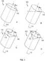
- FIGs. 1A-1Dillustrates a variety of tubular cutting head configurations that can be fabricated from stock tube, according to some embodiments.
- FIG. 1Ashows a cutting head stock tube 100 having a first plane 105 at an angle, ⁇ FP, that is orthogonal to the central axis 110 of the lumen of the stock tube 100.
- FIG. 1Bshows a cutting head stock tube 100 having a first plane 105 at an acute angle, ⁇ FP , to the central axis 110 of the lumen of the stock tube 100, the acute angle ranging from 1° to about 75°.
- FIG. 1Ashows a cutting head stock tube 100 having a first plane 105 at an angle, ⁇ FP, to the central axis 110 of the lumen of the stock tube 100, the acute angle ranging from 1° to about 75°.
- FIG. 1Cshows a cutting head stock tube 100 having a first plane 105 at an acute angle, ⁇ FP , to the central axis 110 of the lumen of the stock tube 100, the acute angle, ⁇ FP , ranging from 1° to about 75°; and, having a second plane 105 at an angle, ⁇ SP , that is orthogonal to the central axis 110 of the lumen of the stock tube 100.
- 1Dshows a cutting head stock tube 100 having a first plane 105 at an acute angle, ⁇ FP , to the central axis 110 of the lumen of the stock tube 100, the acute angle ranging from 1° to about 75°; and, having a second plane 105 at an angle, ⁇ SP, to the central axis 110 of the lumen of the stock tube 100, the acute angle, ⁇ SP , ranging from 1° to about 75°.
- the cutting headcan be fabricated from any material known to one of skill to be suitable in a surgical environment for the uses taught herein.
- a hard material with hardness greater than Rockwell C 30 or greater than Rockwell C 45can be suitable in some embodiments.
- the cutting headcan be comprised of a component selected from the group consisting of tempered steel, stainless steel , high carbon steel , titanium or titanium alloy, ceramic, diamond and obsidian.
- the stainless steelcan comprise 304 stainless steel, 316 stainless steel, 17-4 PH stainless steel, 400 series stainless steel, or any other stainless steels known to one of skill to be suitable for the cutting functions taught herein.
- the cutting headcan be made of cobalt chromium, tungsten carbide, or a ceramic.
- the tube forming the cutting headcan have a wall thickness, for example, from 0.08 mm to 0.51 mm (0.003" to 0.020") or more specifically 0.13 mm to 0.30 mm (0.005" to 0.012").
- the cross-sectional area of the cutting headcan range from 3.05 mm 2 to 38.1 mm 2 (0.120 inches 2 to 1.5 inches 2 ) or, in some embodiments, from 4.57 mm 2 to 10.2 mm 2 (0.180 in 2 to 0.400 in 2 ).
- the width in any directioncan range from 0.20 mm to 10.2 mm (0.080" to 0.400") or more and, in some embodiments, 0.41 mm to 0.64 mm (0.160" to 0.250").
- the cutting headcan have a maximum transverse cross section dimension ranging from about 3.0mm to about 20.0mm, from about 4.0mm to about 15.0mm, from about 4.0mm to about 12.0mm, from about 5.0mm to about 10.0mm, about 5.0mm to about 8.0mm, or any range therein in increments of 0.1mm.
- the cutting headshave diameters of about 4.8mm, about 5.0mm, about 5.2mm, about 5.4mm, about 5.8mm, about 6.0mm, about 6.2mm, about 6.4mm, about 6.6mm, about 6.8mm, about 7.0mm, about 7.2mm, about 7.4mm, about 7.6mm, about 7.8mm, about 8.0mm, about 8.2mm, and any 0.1mm increment therein.
- the distal perimeter of a cutting headcan be on the first plane or the second plane, or a combination thereof, and the cutting surfaces can be any cutting surface known to one of skill, such as a razor surface, a serrated surface, or a sinusoidal surface, in some embodiments.
- the cutting surfacecan have teeth and gullets between the teeth.
- the spacing between the teethcan be equal or variable, and the depth of the gullets can be equal or variable, and any combination of teeth and gullets can be used.
- the direction of the protrusion of the teethcan be offset from the direction of the remainder of the walls of the cutting head.
- the teethare in the same direction as the remainder of the walls of the cutting head, such that the teeth are merely an extension of the walls of the cutting head, with no shift in direction toward the lumen of the cutting head or away from the lumen of the cutting head.
- the patterncan be a sequence of toward, away, toward, away, no shift, and the sequence is repeated around the distal edge of the outer perimeter of the cutting head.
- all teethcan point toward the lumen, and in some embodiments, all teeth can point away from the lumen.
- the teethalternate toward the lumen and away from the lumen tooth-by-tooth.
- the teethare gradually toward and away from the lumen at gradually increases and decreasing angles, tooth-by-tooth, to create an appearance of waves as the teeth circle the distal edge of the outer perimeter.
- the sequencecan also be entirely random.
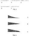
- FIGs. 2A-2Eshow blade configurations, according to some embodiments.
- FIG. 2Ashows a 5 tooth shift pattern of toward, away, toward, away, no shift, repeat.
- FIG. 2Bshows a random shift pattern.
- FIG. 2Cshows a wavy shift pattern.
- FIG. 3Dshows a 3 tooth shift pattern of away, toward, no shift, repeat.
- FIG. 3Eshows a simple away, toward, repeat shift pattern.
- the choice of blade configurationcan be combined with a choice of blade profile, in some embodiments.
- the cutting heads taught hereincan have a variety cutting actions, such as a chisel action, sawing action, slicing action, and ripping action, for example.
- the blade profile chosencan be varied to use any blade profile known to one of skill.
- the teethare beveled.
- the cutting headshave teeth that point backward as well as forward to include forward cutting surfaces in addition to backward cutting "spurs.”
- the teachingsinclude a tubular cutting head for removing a target tissue of a subject.
- the tubecan be an elongated, tubular structure of any shape, such as circular tube, a square tube, a rectangular tube, an elliptical tube, a pentagonal tube, a hexagonal tube, heptagonal, an octagonal tube, and the like, such that any number of sides, curvatures, or combinations thereof can be used in some embodiments.
- a circular tubeis used.
- the cutting headscan have a combination of blade types, for example, forward-cutting blades, backward-cutting blades, and transverse cutting blades, as well as protrusions, hooks, and the like, for grabbing, ripping, or otherwise removing tissue.
- the cutting headcan have a backward cutting blade for cutting the target tissue in a backward stroke of the cutting head, a transverse cutting blade for cutting the target tissue in a transverse stroke of the cutting head, or a combination thereof.
- a transvers utting bladecan be positioned on the blade guard for cutting the target tissue in a transverse stroke of the cutting head.
- FIGs, 3A-3Cshow cross section of individual blade profiles, according to some embodiments.
- FIG. 3Ashows a planar-concave blade profile.
- FIG. 3Bshows a wedge blade profile.
- FIG. 3Cshows a chisel blade profile.
- the bladescan be designed to have any configuration, including a single-edge, double-edge, single barb, double-barb, straight tip, barbed tip, and the like, to assist with any form of tissue removal, including cutting, slicing, chiseling, scraping, gouging, sawing, grinding, and ripping of a tissue for efficiency in removal during a surgery, for example.
- FIGs. 4A-4Cillustrate a cutting head, according to some embodiments in accordance with the invention.
- FIG. 4Ashows an oblique view of the cutting head
- FIG. 4Bshows a lateral view.
- the cutting head 400can have an outer perimeter 405 that circumscribes a lumen 410 through the cutting head 400, the lumen 410 having a central axis 415.
- the cutting head 400can also have a forward cutting blade 420 on a distal edge 425 of the outer perimeter 405, the forward cutting blade 420 configured for (i) cutting a target tissue (not shown) in a forward stroke of the cutting head 400 and (ii) directing the cut tissue into the lumen 410.
- the cutting head 400can also have a blade guard 430 positioned distal to the forward cutting blade 420 and configured to guard a perimeter tissue (not shown) from the forward cutting blade 420 upon the forward stroke the blade guard 430 having a width 433 that is smaller than the width 422 of a transverse cross-section of the lumen 410 to facilitate entry of the target tissue into the lumen 410 on the forward stroke.
- the lateral surfaces 409 of the blade guardcan also be serrated, or otherwise sharp cutting surfaces, for transverse cutting.
- FIG. 4Calso shows such a surgical, tissue removal system that includes a tubular cutting head 400 for removing a target tissue (not shown) of a subject.
- the systemcan include a cutting head 400 having an outer perimeter that circumscribes a flow of suction 444 through the cutting head 400; a lumen 415 circumscribed by the outer perimeter 405, the lumen 410 guiding the flow of suction 444 and having a central axis 415; a forward cutting blade 420 on a distal edge 425 of the outer perimeter 405, the forward cutting blade 420 configured for (i) cutting the target tissue in a forward stroke of the cutting head 400 and (ii) directing the cut tissue into the lumen 410; and, a blade guard 430 positioned distal to the forward cutting blade 420 and configured to guard a perimeter tissue (not shown) from the forward cutting blade 420 upon the forward stroke the blade guard 430.
- the cutting headcan be configured for an operable communication between the lumen 410 and a source of the suction 444, such that the systems 400 include the suction assembly 484 in operable communication with the cutting head 400 for creating the flow of suction 444 for removing the target tissue through the lumen 410 and out of the subject, the suction assembly 484 comprising a rigid suction tube 488 with a central axis.
- the operable communicationincludes the use of one or more suction ports 466 positioned just proximal to the most proximal point of the distal edge of the out perimeter of the cutting head.
- the one or more suction ports 466can be located from about 3mm to about 20mm proximal to the most proximal point of the distal edge 425. While not intended to be bound by any theory or mechanism of action, one of skill will appreciate that a source of additional air can be useful when suctioning within a region that can create vacuum which would otherwise impede or cease the flow of suction that transports excised tissue away from the surgical space during the removal of the tissue.
- the suction ports 466can be used to provide the additional air to avoid creating of the vacuum in the surgical space.
- the suction assembly 484comprises an at least substantially rigid suction tube 488 having a proximal end (not shown) and a distal end 499, the distal end 499 in the operable communication with the cutting head 400, and the distal end 499 configured for communicating with a source of suction 444 for the suction assembly 484.
- the at least substantially rigid suction tube 488can be formed as a single unit with the cutting head 400.
- the phrase, "at least substantially rigid"can refer a component that is rigid, or sufficiently rigid such that the desired function is obtained, under the forces that are created with normal use.
- a desired functionmay be to prevent or inhibit the occurrence of a bending moment of the rigid component at one or more points along the length of a rigid suction tube upon use of the cutting head in the subject.
- the following tabledescribes the dimensional ratios of the cutting head 400 that were found to facilitate fast-and-efficient tissue removal in a discectomy.
- the "Label”is used to show the components and measures that form the ratios in a small device and a large device.
- the rigid suction tubecan comprise any material known to one of skill to be suitable for the uses taught herein.
- the rigid suction tubecan comprise any surgical steel, plastic or resin considered desirable to one of skill for the devices taught herein.
- the rigid suction tubecan comprise the same or similar materials as the cutting head.
- the rigid suction tubecan comprise a stainless steel, polyetheretherketone (PEEK), polyimide, or carbon fiber.
- the wall thickness of the shaftcan be any thickness at which a select material will have the physical properties desired. In some embodiments, the wall thickness can range, for example, from 0.008 mm to 0.51 mm (0.003" to 0.020") and from 0.13 mm to 0.25 mm (0.005" to 0.010") in some embodiments.
- the luminal surface of the tubecan be coated with TEFLON, a hydrophobic coating such as parylene, or a hydrophilic coating such as polyvinyl alcohol or polyethylene glycol.
- the rigid suction tubecan comprise a polymer tube reinforced with a metal braid, a coiled tube, or a tube with transverse slots to facilitate articulation, should articulation be desired in some embodiments.
- the cutting headcan be angled relative to the axis of the rigid suction tube by, for example, pulling on a tendon attached to the cutting head on one side, the tendon running-along a guide on the side of the rigid suction tube.
- FIGs. 5A and 5Billustrate the angulation of a cutting head 500, according to some embodiments in accordance with the invention.
- FIG. 5Ashows that the central axis 515 of the lumen 510 can be at an angle, ⁇ 1 , ranging from about 5° to about 90° from a central axis 555 of the flow of suction 544 at the distal end 599 of the suction assembly (partially shown) 584, and the forward cutting blade 520 can be located about 2mm to about 25mm from the vertex of the angle, ⁇ 1 .
- ⁇ 1can range from about 2mm to about 30mm, from about 2mm to about 30mm, from about 2.5mm to about 25mm, from about 3mm to about 25mm, from about 4mm to about 20mm, from about 5mm to about 15mm, from about 3mm to about 25mm, from about 7mm to about 12mm, from about 8mm to about 10mm, or any range therein in increments of 0.5mm.
- the central axis of the lumenis at an angle, ⁇ 1 , ranging from about 5° to about 90° from the central axis of the rigid suction tube, and the forward cutting blade is located about 3mm to about 25mm from the vertex of the angle, ⁇ 1 .
- the central axis of the lumenhas a point of exit at the forward cutting blade, and the point of exit is located at a transverse distance of about 3mm to about 25mm that is orthogonal to the central axis of the rigid suction tube
- the central axis of the lumenis at an angle, ⁇ 1 , ranging from 1° to 180° from a central axis of the flow of suction at the distal end of the suction assembly, and the forward cutting blade is located 3mm to 25mm from the vertex of the angle, ⁇ 1 .
- additional angle, ⁇ 3is located 5mm to 25mm proximal to ⁇ 1 , and angles ⁇ 1 and ⁇ 3 are independently selected to range from about 0° to about 180°, with the limitation that (i) the net angle, ⁇ 4 , between the central axis of the lumen of the cutting head and the central axis of a rigid suction tube located proximal to ⁇ 3 ranges from 0° to 90°; and, (ii) the distance between the central axis of the lumen of the cutting head and the central axis of the rigid suction tube ranges from 2mm to 30mm.
- the distance in the flow of suction between angles ⁇ 1 and ⁇ 3can range from about 5mm to about 30mm, from about 5mm to about 25mm, from about 5mm to about 20mm, from about 6mm to about 18mm, from about 7mm to about 15mm, or any range or distance therein in increments of 1mm.
- the operable communication between the cutting head 500 and the suction assembly 584can be articulating, and the angle, ⁇ 1 , can be adjustable.
- the operable communication between the cutting head 500 and the suction assembly 584can be rigid, and the angle, ⁇ 1 , can be fixed.
- the angle, ⁇ 1can range from 0° to about 45°, from about 1° to about 40°, from about 5° to about 35°, from 10° to about 35°, from 15° to about 40°, from 20° to about 30°, or any range therein in increments of 1°.
- the angle, ⁇ 1can be about 3°, about 5°, about 10°, about 15°, about 20°, about 25°, about 30°, about 35°, about 40°, about 45°, or any angle therein in increments of 1°.
- the backward cutting bladecan be positioned on the distal edge 525 of the outer perimeter 505 for cutting the target tissue in the backward stroke of the cutting head 500.
- the backward cutting blade 531can be positioned on the blade guard 530 for cutting the target tissue in the backward stroke of the cutting head 500.
- FIG. 5Bshows that the blade guard 530 can have a double-edged blade tip as the backward cutting blade 531 point back into the lumen 515 at an angle, ⁇ 2 , of greater than 90° from the central axis 515 of the lumen 500 to trap and/or cut tissue in the lumen 510 in the backwards stroke of the cutting head 500.
- the backward cutting blade 531can be referred to as a "talon” in some embodiments, or "pincer", as it can function to grab, shear, and hook tissue for removal.
- the target tissuecan be a nucleus pulposus
- the perimeter tissuecan be an annulus fibrosis, for example.
- a surgical, tissue removal system for a discectomycan comprise a tubular cutting head for removing a nucleus pulposus from a subject.
- the systemscan include a cutting head having an outer perimeter that circumscribes a flow of suction through the cutting head; a lumen circumscribed by the outer perimeter, the lumen guiding the flow of suction; a forward cutting blade on a distal edge of the outer perimeter, the forward cutting blade configured for (i) cutting the nucleus pulposus in a forward stroke of the cutting head and (ii) directing the cut nucleus pulposus into the lumen; a backward cutting blade for cutting the nucleus pulposus in a backward stroke of the cutting head; a transverse cutting blade for cutting the nucleus pulposus in a transverse stroke of the cutting head; and, a blade guard positioned distal to the forward cutting blade and configured to guard an annulus fibrosis tissue from the forward cutting blade upon the forward stroke.
- the devices taught hereincan operate without substantial clogging from the flow of excised tissue from the cutting head, and this was accomplished by design. Without intending to be bound by any theory or mechanism of action, it was discovered that the area of a transverse cross-section of the distal end of the cutting head should be at least substantially equal to, or less than, the transverse cross-sectional area of any point that is positioned proximal to the distal end of the cutting head leading to collection of the flow of excised tissue from the cutting head.
- Such pointswould include, for example, any such point of cross-section along the rigid suction tube, or any other component of the section assembly leading to the point of collection of the excised tissue, for example, the most proximal orifice at which the pressure difference dumps the excised tissue into a collection canister in some embodiments.
- the term "at least substantially equal to”means that there may be a smaller transverse cross-sectional area, as long as it is limited in magnitude, in some embodiments.
- the transverse cross-sectional areacan be at least substantially equal to the transverse cross-sectional area of the cutting head if it is no more than 20% less in transverse cross-sectional area at the proximally located cross-section.
- the transverse cross-sectional areacan be at least substantially equal to the transverse cross-sectional area of the cutting head if it is no more than about 3%, about 5%, about 7%, about 9%, about 11%, about 13%, about 15%, about 17%, about 19%, about 21% less in transverse cross-sectional area at the proximally located cross-section. Any percent therein in increments of 1%, less in transverse cross-sectional area at the proximally located cross-section.
- the teachingsalso include a method of removing a target tissue from a subject.
- the methodcan comprise creating an opening in a subject for access to a target tissue; inserting a cutting head taught herein through the opening to access the target tissue in the subject; imaging the depth of the tip of the cutting head using a suitable imaging technique, such as fluoroscopy; and, forcing the cutting head in a forward direction on a surface comprising the target tissue to remove the target tissue while vacuum is activated to suck cut tissue proximally.
- the forward directioncan include a force vector that moves (i) at least substantially on a plane containing the central axis of the lumen of the cutting head, (ii) at least substantially on the surface comprising the target tissue, and (iii) toward the perimeter tissue that is protected by the blade guard.
- the methodcan include capturing the target tissue in the lumen of the cutting head, as well as removing the target tissue through the lumen and out of the subject.
- the phrase, "at least substantially on...,”can refer to a position or movement that is sufficient close to the exact desired position such that the desired function is obtained, under the forces and conditions that are created with normal use of the systems and devices taught herein.
- “at least substantially on a plane containing the central axis of the lumen of the cutting head” or at least substantially on the surface comprising the target tissue”can refer to a position or movement that is parallel or substantially parallel to the plane or surface but perhaps off by about 1um to about 15mm from the actual plane, or perhaps off by about 0.1° to about 20° in direction of movement.
- the measure of "at least substantially”is used to approximate situations in which the exact measure or position is not obtained, but function desired by a person of ordinary skill is obtained.
- a reduction of outcome when compared to the best possible outcomecan be used to determine what is "at least substantially" the desired outcome.
- the desired outcomeis at least substantially obtained where the best possible outcome is reduced by less than 10%, less than 15%, less than 20%, less than 30%, less than 40% or less than 50%.
- the desired outcomeis at least substantially obtained where the best possible outcome is reduced by an amount of about 5% to about 30%, about 7% to about 35%, about 10% to about 25%, or any range therein in increments of 1%.
- the opening in the subjectcan vary, depending on the disk height of the subject, which is often in the range of about 5mm-7mm. In some embodiments, the opening in the subject can range in size from about 4mm x 4mm to about 14mm x 14mm. In some embodiments, the opening can be about 10mm x 7mm.
- the methodcomprises forcing a cutting head taught herein in a backward direction on a surface comprising the target tissue to remove the target tissue.
- the backward directioncan include a force vector that moves (i) at least substantially on a plane containing the central axis of the lumen of the cutting head, (ii) at least substantially on the surface comprising the target tissue, and (iii) away from the perimeter tissue that is protected by the blade guard.
- the methodcomprises forcing a cutting head taught herein in a transverse direction on a surface comprising the target tissue to remove the target tissue.
- the transverse directioncan include a force vector that moves (i) at an angle ranging from about 15° to about 165° from a plane containing the central axis of the lumen of the cutting head, (ii) at least substantially on the surface comprising the target tissue, and (iii) in contact with the perimeter tissue that is protected by the blade guard.
- the cutting heads taught hereinare sharp and can be harmful to tissues during entry and exit of the cutting heads through the surgical opening.
- An obturator, guard cannulais provided in some embodiments to protect a subject during entry and exit of an elongated surgical cutting device having a non-linearity.
- FIG. 6illustrates an obturator, guard cannula, according to some embodiments.
- the guard cannula 600can comprise an entry hub 605 having an inner perimeter 615, an outer perimeter 625, and an irrigation port 635 that communicates between the inner perimeter 615 with the outer perimeter 625; and, a linear, elongated split-tube 650 having a proximal end 655, a distal end 665, and a lumen 675.
- the proximal end 655 of the split-tube 650can (i) circumscribe at least a portion of the inner perimeter 615 of the hub 605 and (ii) be in operable communication with the irrigation port 635.
- the communicationcan be operable to receive an irrigation fluid 690 from the irrigation port 635, the transport of the irrigation fluid 690 to a target tissue (not shown) including, for example, a movement of the irrigation fluid 690 from the irrigation port 635 to the distal end 665 of the split-tube 650 on a luminal surface 680 of the split-tube 650.
- the irrigation fluidcan be any fluid desired by one of skill, including liquids and gases.
- the irrigation fluidcan be aqueous.
- the irrigation fluidcan be non-aqueous.
- the irrigation fluidcan be an emulsion.
- the irrigation fluidcan comprise a gas.
- aqueous irrigation fluidsinclude water, saline, or an aqueous surfactant containing liquid.
- non-aqueous fluidscan include any oilbased liquid that may help facilitate tissue extraction during a surgical procedure.
- gasescan include carbon dioxide, nitrogen, air, and any inert or at least substantially nonreactive gases.
- the irrigation fluidcan include a lubricant, such as glycerin, silicon oil, and the like.
- Irrigation fluidscan be used as a carrier to help remove an excised tissue, or to help inhibit the creation of a vacuum within a surgical site that can inhibit the removal of the excised tissue.
- An example of such as a vacuumis one that may be created during use of a suction within a closed cavity such as an intervertebral space within an annulus during a discectomy.
- the distal end 665 of the split-tube 650can also have any configuration desired by one of skill.
- the distal end 665can be at least substantially pointed and/or non-blunt.
- the distal end 665can be at least substantially blunt to avoid damage to an entry tissue upon contact of the distal end 665 with the entry tissue.
- the split-tube 650can also have a length ranging from about 10cm to about 60 cm and a width ranging from about 5mm to about 16mm.
- the split in the split-tube 650can compose a gap 667 having a width ranging from about 4mm to about 14mm, the split accommodating a non-linearity in the surgical device.
- the cutting heads taught hereincan have a diameter that is smaller than that of the portion of the suction assembly that passes through the lumen of the guard cannula, such that the guard cannula holds the suction assembly 484 but allows the cutting head 400 to pass through the gap 667.
- the gap 667can have a width that exceeds the diameter of the cutting head 400 but is less than the diameter of the rigid suction tube 488, and the lumen of the guard cannula 600 has a diameter that exceeds the diameter of the rigid suction tube 488.
- the systems taught hereincan be used in a variety of procedures for removal of a target tissue from a subject including, for example, removal of a meniscus or a discectomy.
- the surgical cutting device used with the guard cannulacan be a discectomy device.
- the entry tissueincludes the subject's epithelial tissue, muscle tissue, nerve tissue, connective tissue, a blood vessel, bone, cartilage, or a combination thereof, leading to the nucleus pulposus.
- the target tissuecan include the nucleus pulposus in some embodiments.
- kitshaving a surgical tissue removal system and a guard cannula is provided, the kit using any combination of system and cannula embodiments taught herein.
- the kitscan be a discectomy kit.
- the entry tissueincludes the subject's epithelial tissue, muscle tissue, nerve tissue, connective tissue, a blood vessel, bone, cartilage, or a combination thereof, leading to the nucleus pulposus.
- the target tissuecan include the nucleus pulposus in some embodiments.
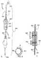
- FIG. 7illustrates a surgical tissue removal kit, according to some embodiments.
- the kit 700includes a cutting head 400, a suction assembly 484, and an obturator, guard cannula 600.
- a flow of suction 444 from the suction assembly 484enters the cutting head 400 to remove a target tissue excised by the cutting head.
- Irrigation water 690can enter irrigation valve 795 and/or the irrigation port 635, the irrigation water 690 coming from the irrigation valve 795 is used when the suction 444 is off, and the irrigation water 690 coming from the irrigation port 635 can be used when the suction 444 is on, during which the suction 444 draws the irrigation water 690 between the luminal surface of the guard cannula 600 and the suction assembly 484 into the surgical area (not shown).
- the guard cannula 600protects the entry tissue (not shown) while the cutting head 400 and suction assembly 484 moves relative to the entry tissue during a surgical procedure, the cutting head 400 moving, for example, in a forward, backward, and/or transverse motion to excise and remove the target tissue.
- kits to remove a target tissuecomprises creating an opening in a subject for access to a target tissue; inserting the cutting head of the kit through the entry hub and the elongated split-tube of the guard cannula of the kit; inserting the cutting head of the kit through the opening to access the target tissue in the subject while protecting the entry tissue with the blunt, distal end of the split-tube.
- methods of using the tissue removal systemsare the same or similar to those taught herein.
- the target tissuecan be a nucleus pulposus
- the perimeter tissuecan be an annulus fibrosis.
- a kit with a guard cannulathat helps protect the subject's epithelial tissue, muscle tissue, nerve tissue, connective tissue, a blood vessel, bone, cartilage, or a combination thereof, leading to the nucleus pulposus in such procedures.
- FIGs. 8A-8Cillustrate a system or kit that can irrigate concurrent with application of suction, and without the obturator, guard cannula in place, according to some embodiments.
- FIG. 8Ashows the complete discectomy system 800 including the cutting head 400, a means for applying suction through the suction assembly 884, a control handle 886 and a vacuum attachment 892, an irrigation tube 804, an irrigation control 802, and an optional vacuum control 888.
- the handle 886can have a knob (not shown) that turns to tension a pull cable to flex or straighten the cutting head relative to the rigid suction tube, or a slide that tensions the cable to flex or straighten the cutting head relative to the rigid suction tube.
- the cables to flex and straightencan be on opposing sides of the shaft constrained to small side lumens attached to the outer surface of the shaft to flex and straighten out the cutting head.
- FIG. 8Bshows a cross-sectional view of the irrigation tube 804 relative to the rigid suction tube 894.
- FIG. 8Cshows a cross-sectional view of the control handle 886 and internal piping.
- a variety of cutter headswere tested in 3 cadaver laboratories on 28 discs. The results were compared to determine the most efficient cutter head design.
- a desirable cutter head designwas one that would cut well on all target tissues, including the nucleus pulposus, vertebral endplates, and inner annulus tissue.
- the cutter headshould also cut the target tissues in a desired manner while providing little to no damage to the perimeter tissue, such tissue including the perimeter annulus fibrosis tissue that should be preserved as a desirable perimeter structure.
- the designshould remove tissue quickly under suction, such that the configuration of the head facilitates the removal of the tissue under suction.
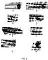
- FIGs. 9A-9Gshow cutting head designs that were tested, according to some embodiments.
- the design in FIG. 9Acut well but it was not as safe to the annulus as other designs.
- the design in FIG. 9Bwas safe to the annulus but it did not cut tough tissue well and showed too much resistance.
- the design in FIG. 9Calso did not penetrate tough tissue well.
- the design in FIG. 9Ddid cut and decorticate well, but it clogged on soft/elastic tissue.
- the design in FIG. 9Ecut tough tissue well and did not clog, and it also decorticates really well. It was also safe to the annulus. The shape of the device however, did not reach the far side of the nucleus pulposus.
- the design in FIG. 9Acut well but it was not as safe to the annulus as other designs.
- the design in FIG. 9Bwas safe to the annulus but it did not cut tough tissue well and showed too much resistance.
- the design in FIG. 9Calso did not penetrate tough tissue well.
- FIG. 9Fshows a bend that was introduced to the device to enable the cutting head of FIG. 9E to reach the far side of the nucleus pulposus.
- the design in FIGs. 9G and 9Hshowed the most efficient cutting head performance identified in the testing, removing 23cc of material in 5 minutes.
- This examplefurther developed the designs of the cutting heads.
- the design in FIGs. 8G and 8Hwere further investigated in 7 cadaver labs and 28 discs.
- FIGs. 10A-10Eillustrate the advancements in the cutting head, according to some embodiments.
- the design in FIG. 10Ashows a cutting head having a bevel on the outer surface of the cutting teeth, and the device cut poorly and gouged soft bone.
- the design in FIG. 10Bshows an oval cutting head not having the bevel on the outer surface of the cutting teeth, and the device had inconsistent cutting and gouged soft bone.
- the design in FIG. 10Cwas shown for a comparison result using a ring curette, and the device gouged soft bone.
- the design in FIG. 10Dshows a short cutting head with a single "talon" or pincer, and the device showed the most appealing results to date with optimal cutting and no gouging.
- FIG. 10Eis another proposed design, configured to perform with the efficiency of the design of FIG. 10D , with the addition of a second talon that bends away from the lumen of the cutting head to serve as an additional talon and blade guard.
- This exampledescribes an alternate embodiment that was tested, referred to as the serpentine or bayonet configuration, in which the rigid suction tube 488 can have at least two angles; an angle ⁇ 1 , and an angle ⁇ 3 .
- FIGs. 11A-11Cillustrate a bayonet-type communication between a cutting head and a suction assembly, according to some embodiments. It was discovered that the distal end of the rigid suction tube 488 can be redirected in bayonet, or serpentine, fashion in order to facilitate an improved access of the cutting head to a target tissue during a discectomy, for example. As shown in FIGs.
- Angles ⁇ 1 and ⁇ 3can each be independently selected to range from about 0° to about 180°, with the limitation that (i) the net angle, ⁇ 4 , that is realized between the central axis 415 of the lumen 410 of the cutting head 400 and the central axis 497 of the rigid suction tube 488 (extended as directed proximal to ⁇ 1 ) ranges from 0° to 90°; and, (ii) the distance 498 between the central axis 415 of the lumen 410 of the cutting head 400 and the central axis 497 of the rigid suction tube 488 can range from about 2mm to about 30mm.
- the central axis of the lumencan have a point of exit at the forward cutting blade, and the point of exit is located at a transverse distance of about 3mm to about 25mm
- the distance 498can be about 2mm, about 3mm, about 4mm, about 5mm, about 6mm, about 7mm, about 8mm, about 9mm, about 10mm, about 12mm, about 14mm, about 16mm, about 18mm, about 20mm, about 22mm, about 24mm, about 26mm, about 28mm, about 30mm, and any distance or range therein in increments of 0.5mm.
- the distance between the vertex of ⁇ 3 and the distal end of the cutting head 400can range from about 5mm to about 25mm, from about 6mm to about 20mm, from about 7mm to about 15mm, or any range therein in increments of 1mm.
Landscapes
- Health & Medical Sciences (AREA)
- Life Sciences & Earth Sciences (AREA)
- Surgery (AREA)
- Engineering & Computer Science (AREA)
- Biomedical Technology (AREA)
- Animal Behavior & Ethology (AREA)
- General Health & Medical Sciences (AREA)
- Heart & Thoracic Surgery (AREA)
- Veterinary Medicine (AREA)
- Public Health (AREA)
- Orthopedic Medicine & Surgery (AREA)
- Molecular Biology (AREA)
- Nuclear Medicine, Radiotherapy & Molecular Imaging (AREA)
- Medical Informatics (AREA)
- Neurology (AREA)
- Cardiology (AREA)
- Oral & Maxillofacial Surgery (AREA)
- Transplantation (AREA)
- Vascular Medicine (AREA)
- Surgical Instruments (AREA)
- Prostheses (AREA)
Description
- The teachings provided herein are generally directed to a safe and efficient cutting head for removing a target tissue from a subject during a surgical procedure.
- Intervertebral disc disease is a major worldwide health problem. In the United States alone almost 700,000 spine procedures are performed each year and the total cost of treatment of back pain exceeds $30 billion. Age related changes in the disc include diminished water content in the nucleus and increased collagen content by the 4.sup.th decade of life. Loss of water binding by the nucleus results in more compressive loading of the annulus. This renders the annulus more susceptible to delamination and damage. Damage to the annulus, in turn, accelerates disc degeneration and degeneration of surrounding tissues such as the facet joints.
- The two most common spinal surgical procedures performed are discectomy and spinal fusion. These procedures only address the symptom of lower back pain, nerve compression, instability and deformity. The objective of the spinal disc fusion procedure is to restore, maintain and stabilize disc height, and/or reduce back pain. The procedure is generally performed by removing central disc material such and inner annulus, nucleus pulposus and the cartilage on the endplates before replacing with bone graft and a scaffold to effect fusion of the vertebral bodies within the treated disc for height stabilization. This removal process is called a discectomy and is both tedious and frequently inadequate which can result in compromised fusion, as well as traumatic and time consuming due to the large incision and dissections required to expose the disc for discectomy.
- In a typical discectomy procedure, a nucleotomy is first performed in which the nucleus is loosened by using a curette or a manual shaver to shear the nucleus loose and then removed using a rigid grasper called a rongeur. The surgeon has to insert the rongeur through an opening in the disc called an anulotomy, grasp nucleus and remove out of the disc and the surgical access, clean the jaws and reinsert for more grasping of disc repeatedly. This process can pose safety issues for tissues in between tool passage such as nerves. Furthermore, disc debris left behind can hinder efficient subsequent tissue removal and insertion of the discectomy tools into the disc. The second step is decortication in which cartilage attached to the bone (cartilaginous endplate) is removed by the use of rigid scrapers such as a curette or a rasp to help promote a strong intervertebral fusion. Peeled cartilage are removed by scooping with a curette and withdrawn out of the body by the use of a rongeur. Tissue debris left behind can also compromise efficiency and effectiveness of the decortication resulting in a weaker fusion. Moreover, corners inside the discs are often hard to reach by current state-of-the art tools, often leaving additional areas of inadequate disc removal.
- In addition, state-of-the-art systems using a combination of suction and cutting suffer clogging problems due to excised tissue becoming lodged in the system. One of skill will appreciate that problems with clogging during a surgical procedure can be problematic, and a solution to such clogging problems is highly desired.
- Although several advanced tools have been developed, none have addressed all of these issues adequately. One of skill in the art would certainly appreciate a discectomy system that is (i) less tedious and time consuming to use, (ii) less prone to clogging by excised tissue; (iii) safer to the subject undergoing the surgery, and (iv) more effective in promoting a strong intervertebral fusion.
US 2006/030785 A1 discloses a surgical, tissue removal biopsy system for removing a target tissue of a subject, comprising a cutting head 102 having an outer perimeter that circumscribes a lumen through the cutting head, the lumen having a central axis and a excising cutting finger.- The teachings provided herein are generally directed to a safe and efficient cutting head for removing a target tissue from a subject during a surgical procedure. The target tissue can include any tissue that is accessible through a small surgical opening, for example, a joint tissue such as a meniscus, in some embodiments, or an intervertebral tissue, such as a nucleus pulposus, in other embodiments. The invention is described in
claim 1. Preferred embodiments of the invention are described in the dependent claims. - The cutting head can be tubular with a cutting surface forming at least a first plane on a distal perimeter of cutting head, the cutting head in operable communication with a suction device to excise a target tissue in a manner that facilitates an ease of removal of the tissue with the suction. The cutting surface can be flat, sinusoidal, or serrated, for example, and the first plane of the cutting surface may be at an angle, θFP, that deviates up to 75° from a position that is orthogonal to the central axis of the cutting head. In some embodiments, the cutting surface can have a second plane may be at an angle, θSP, that deviates up to 75° from a position that is orthogonal to the central axis of the cutting head. In some embodiments, the cutting head has a cutting blade and a blade guard for guarding a perimeter tissue from the cutting blade.
- As such, the teachings include a tubular cutting head for removing a target tissue of a subject. In these embodiments, the cutting head can have an outer perimeter that circumscribes a lumen through the cutting head, the lumen having a central axis. The cutting head can also have a forward cutting blade on a distal edge of the outer perimeter, the forward cutting blade configured for (i) cutting a target tissue in a forward stroke of the cutting head and (ii) directing the cut tissue into the lumen. And, the cutting head can also have a blade guard positioned distal to the forward cutting blade and configured to guard a perimeter tissue from the forward cutting blade upon the forward stroke the blade guard having a width that is smaller than the width of a transverse cross-section of the lumen to facilitate entry of the target tissue into the lumen on the forward stroke.
- In some embodiments, the cutting head can have a backward cutting blade for cutting the target tissue in a backward stroke of the cutting head, a transverse cutting blade for cutting the target tissue in a transverse stroke of the cutting head, or a combination thereof. In some embodiments, a transverse cutting blade can be positioned on the blade guard for cutting the target tissue in a transverse stroke of the cutting head.
- According to the invention, the backward cutting blade is positioned on the distal edge of the outer perimeter for cutting the target tissue in the backward stroke of the cutting head. In some embodiments, the backward cutting blade can be positioned on the blade guard for cutting the target tissue in the backward stroke of the cutting head, the blade guard having a double-edged blade tip point back into the lumen at an angle, θ2, of greater than 90° to trap and/or cut tissue in the lumen in the backwards stroke of the cutting head.
- Since the cutting head can be designed to remove tissue through use of a suction, the teachings are also directed to systems of a cutting head that operably connect the cutting head with a suction assembly. As such, the teachings include a such a surgical, tissue removal system that includes a tubular cutting head for removing a target tissue of a subject. The system can include a cutting head having an outer perimeter that circumscribes a flow of suction through the cutting head; a lumen circumscribed by the outer perimeter, the lumen guiding the flow of suction and having a central axis; a forward cutting blade on a distal edge of the outer perimeter, the forward cutting blade configured for (i) cutting the target tissue in a forward stroke of the cutting head and (ii) directing the cut tissue into the lumen; and, a blade guard positioned distal to the forward cutting blade and configured to guard a perimeter tissue from the forward cutting blade upon the forward stroke the blade guard. In some embodiments, the blade guard can have a width that is smaller than the width of a transverse cross-section of lumen to facilitate entry of the target tissue into the lumen on the forward stroke.
- The cutting head can be configured for an operable communication between the lumen and a source of a suction, such that the systems include a suction assembly in operable communication with the cutting head for creating the flow of suction for removing the target tissue through the lumen and out of the subject, the suction assembly comprising a rigid suction tube with a central axis. In some embodiments, the operable communication includes the use of one or more suction ports positioned just proximal to the most proximal point of the distal edge of the out perimeter of the cutting head. In some embodiments, the one or more ports can be located from about 3mm to about 20mm proximal to the most proximal point of the distal edge.
- In some embodiments, the suction assembly comprises an at least substantially rigid suction tube having a proximal end and a distal end, the distal end in the operable communication with the cutting head, and the distal end configured for communicating with a source of suction for the suction assembly. In some embodiments, the at least substantially rigid suction tube can be formed as a single unit with the cutting head.
- In some embodiments, the central axis of the lumen is at an angle, θ1, ranging from about 5° to about 90° from the central axis of the rigid suction tube, and the forward cutting blade is located about 3mm to about 25mm from the vertex of the angle, θ1.
- The system of claim 10, the central axis of the lumen has a point of exit at the forward cutting blade, and the point of exit is located at a transverse distance of about 3mm to about 25mm that is orthogonal to the central axis of the rigid suction tube.
- In some embodiments, the central axis of the lumen can be at an angle, θ1, ranging from about 5° to about 90° from a central axis of the flow of suction at the distal end of the suction assembly, and the forward cutting blade can be located about 3mm to about 25mm from the vertex of the angle, θ1. In some embodiments, the operable communication between the cutting head and the suction assembly can be articulating, and the angle can be adjustable. In some embodiments, the operable communication between the cutting head and the suction assembly can be rigid, and the angle can be fixed.
- In some embodiments, the central axis of the lumen is at an angle, θ1, ranging from 1° to 180° from a central axis of the flow of suction at the distal end of the suction assembly, and the forward cutting blade is located 3mm to 25mm from the vertex of the angle, θ1. In these embodiments, additional angle, θ3, is located 5mm to 25mm proximal to θ1, and angles θ1 and θ3 are independently selected to range from about 0° to about 180°, with the limitation that (i) the net angle, θ4, between the central axis of the lumen of the cutting head and the central axis of a rigid suction tube located proximal to θ3 ranges from 0° to 90°; and, (ii) the distance between the central axis of the lumen of the cutting head and the central axis of the rigid suction tube ranges from 2mm to 30mm.
- It should be appreciated that the cutting heads and systems taught herein have a variety of applications known to one of skill. In some embodiments, the target tissue can be a nucleus pulposus, and the perimeter tissue can be an annulus fibrosis, for example.
- As such, the teachings are also directed to a surgical, tissue removal system for a discectomy, and the systems can comprise a tubular cutting head for removing a nucleus pulposus from a subject. In these embodiments, the systems can include a cutting head having an outer perimeter that circumscribes a flow of suction through the cutting head; a lumen circumscribed by the outer perimeter, the lumen guiding the flow of suction; a forward cutting blade on a distal edge of the outer perimeter, the forward cutting blade configured for (i) cutting the nucleus pulposus in a forward stroke of the cutting head and (ii) directing the cut nucleus pulposus into the lumen; a backward cutting blade for cutting the nucleus pulposus in a backward stroke of the cutting head; a transverse cutting blade for cutting the nucleus pulposus in a transverse stroke of the cutting head; and, a blade guard positioned distal to the forward cutting blade and configured to guard an annulus fibrosis tissue from the forward cutting blade upon the forward stroke. And, the blade guard can have a width, for example, that is smaller than the width of a transverse cross-section of the lumen to facilitate entry of the target tissue into the lumen on the forward stroke.
- The teachings also include a method of removing a target tissue from a subject. In these embodiments, the method can comprise creating an opening in a subject for access to a target tissue; inserting a cutting head taught herein through the opening to access the target tissue in the subject; and, forcing the cutting head in a forward direction on a surface comprising the target tissue to remove the target tissue. The forward direction can include a force vector that moves (i) at least substantially on a plane containing the central axis of the lumen of the cutting head, (ii) at least substantially on the surface comprising the target tissue, and (iii) toward the perimeter tissue that is protected by the blade guard. And, the method can include capturing the target tissue in the lumen of the cutting head, as well as removing the target tissue through the lumen and out of the subject.
- In some embodiments, the method comprises forcing a cutting head taught herein in a backward direction on a surface comprising the target tissue to remove the target tissue. The backward direction can include a force vector that moves (i) at least substantially on a plane containing the central axis of the lumen of the cutting head, (ii) at least substantially on the surface comprising the target tissue, and (iii) away from the perimeter tissue that is protected by the blade guard.
- In some embodiments, the method comprises forcing a cutting head taught herein in a transverse direction on a surface comprising the target tissue to remove the target tissue. The transverse direction can include a force vector that moves (i) at an angle ranging from about 15° to about 150° from a plane containing the central axis of the lumen of the cutting head, (ii) at least substantially on the surface comprising the target tissue, and (iii) in contact with the perimeter tissue that is protected by the blade guard.
- The teachings are also directed to an obturator, guard cannula to protect a subject during entry and exit of an elongated surgical cutting device having a non-linearity. In these embodiments, the guard cannula can comprise an entry hub having an inner perimeter, an outer perimeter, and an irrigation port that communicates between the inner perimeter with the outer perimeter; and, a linear, elongated split-tube having a proximal end, a distal end, and a lumen. In these embodiments, the proximal end of the split-tube can (i) circumscribe at least a portion of the inner perimeter of the hub and (ii) be in operable communication with the irrigation port. In these embodiments, the communication can be operable to receive an irrigation fluid from the irrigation port, the transport of the irrigation fluid to a target tissue including, for example, a movement of the irrigation fluid from the irrigation port to the distal end of the split-tube on a luminal surface of the split-tube.
- The distal end of the split-tube can also have any configuration desired by one of skill. For example, the distal end can at least substantially pointed and/or sharp. In some embodiments, the distal end can be at least substantially blunt to avoid damage to an entry tissue upon contact of the distal end with the entry tissue. The split-tube can also have a length ranging from about 10cm to about 60 cm and a width ranging from about 5mm to about 16mm. Moreover, the split in the split-tube can compose a gap having a width ranging from about 4mm to about 14mm, the split accommodating a non-linearity in the surgical device.
- As described above, the systems taught herein can be used in a variety of procedures for removal of a target tissue from a subject including, for example, removal of a meniscus or a discectomy. In some embodiments, the surgical cutting device used with the guard cannula can be a discectomy device. And, in some embodiments, the entry tissue includes the subject's epithelial tissue, muscle tissue, nerve tissue, connective tissue, a blood vessel, bone, cartilage, or a combination thereof, leading to the nucleus pulposus. As such, the target tissue can include the nucleus pulposus in some embodiments.
- The teachings are also directed to a surgical tissue removal kit having a surgical tissue removal system and a guard cannula, using any combination of system and cannula embodiments taught herein. In some embodiments, the kits can be a discectomy kit. As such, in some embodiments, the entry tissue includes the subject's epithelial tissue, muscle tissue, nerve tissue, connective tissue, a blood vessel, bone, cartilage, or a combination thereof, leading to the nucleus pulposus. As such, the target tissue can include the nucleus pulposus in some embodiments.
- The teachings are also directed to a method of using the kits to remove a target tissue. In some embodiments, the method comprises creating an opening in a subject for access to a target tissue; inserting the cutting head of the kit through the entry hub and the elongated split-tube of the guard cannula of the kit; inserting the cutting head of the kit through the opening to access the target tissue in the subject while protecting the entry tissue with the blunt, distal end of the split-tube. Otherwise, methods of using the tissue removal systems are the same or similar to those taught herein. One of skill will appreciate having such kits for discectomies, for example, in which the target tissue can be a nucleus pulposus, and the perimeter tissue can be an annulus fibrosis. One of skill will also appreciate having a kit with a guard cannula that helps protect the subject's epithelial tissue, muscle tissue, nerve tissue, connective tissue, a blood vessel, bone, cartilage, or a combination thereof, leading to the nucleus pulposus in such procedures.
- One of skill will appreciate that the embodiments taught herein are provided for purposes of outlining general concepts, and that several additional embodiments are included in, and can be derived from, the teachings provided herein.
FIGs. 1A-1D illustrates a variety of tubular cutting head configurations that can be fabricated from stock tube, according to some embodiments.FIGs. 2A-2E show blade configurations, according to some embodiments.FIGs. 3A-3C show cross section of individual blade profiles, according to some embodiments.FIGs. 4A-4C illustrate a cutting head, according to some embodiments.FIGs. 5A and 5B illustrate the angulation of a cuttinghead 500, according to some embodiments.FIG. 6 illustrates an obturator, guard cannula, according to some embodiments.FIG. 7 illustrates a surgical tissue removal kit, according to some embodiments.FIGs. 8A-8C illustrate a system or kit that can irrigate concurrent with application of suction, and without the obturator, guard cannula in place, according to some embodiments.FIGs. 9A-9G show cutting head designs that were tested, according to some embodiments.FIGs. 10A-10E illustrate the advancements in the cutting head, according to some embodiments.FIGs. 11A-11C illustrate a bayonet-type communication between a cutting head and a suction assembly, according to some embodiments.- The teachings provided herein are generally directed to a safe and efficient cutting head for removing a target tissue from a subject during a surgical procedure. The target tissue can include any tissue that is accessible through a small surgical opening, for example, a joint tissue such as a meniscus or an intervertebral tissue, such as a nucleus pulposus. In some embodiments, the devices taught herein can be referred to as an orthopedic tissue removal device. In some embodiments, the devices taught herein are useful in X-LIF (lateral approach to an intervertebral fusions) procedures, T-LIF (transforaminal approach to intervertebral fusions) procedures, P-LIF (posterior approach to intervertebral fusions), or a percutaneous, transforaminal approach (Kambin triangle access).
- The term "subject" and "patient" can be used interchangeably in some embodiments and refer to an animal such as a mammal including, but not limited to, non-primates such as, for example, a cow, pig, horse, cat, dog, rat and mouse; and primates such as, for example, a monkey or a human. As such, the terms "subject" and "patient" can also be applied to non-human biologic applications including, but not limited to, veterinary, companion animals, commercial livestock, and the like.
- The cutting head can be tubular with a cutting surface forming at least a first plane on a distal perimeter of cutting head, the cutting head in operable communication with a suction device to excise a target tissue in a manner that facilitates an ease of removal of the tissue with the suction.
- The cutting surface can be flat, sinusoidal, or serrated, for example, and the first plane of the cutting surface may be at an angle, θFP, that deviates up to 75° from a position that is orthogonal to the central axis of the cutting head. In some embodiments, the cutting surface can have a second plane may be at an angle, θSP, that deviates up to 75° from a position that is orthogonal to the central axis of the cutting head. In some embodiments, the cutting head has a cutting blade and a blade guard for guarding a perimeter tissue from the cutting blade. In some embodiments, θFP and θSP can be independently selected to range from 0° to about 75°, from about 5° to about 75°, from about 10° to about 70°, from about 15° to about 65°, from about 10° to about 60°, from about 5° to about 55°, from about 15° to about 50°, from about 20° to about 45°, from about 15° to about 40°, from about 25° to about 35°, or any angle or range of angles therein in increments of 1°.
FIGs. 1A-1D illustrates a variety of tubular cutting head configurations that can be fabricated from stock tube, according to some embodiments.FIG. 1A shows a cuttinghead stock tube 100 having afirst plane 105 at an angle, θFP, that is orthogonal to thecentral axis 110 of the lumen of thestock tube 100.FIG. 1B shows a cuttinghead stock tube 100 having afirst plane 105 at an acute angle, θFP, to thecentral axis 110 of the lumen of thestock tube 100, the acute angle ranging from 1° to about 75°.FIG. 1C shows a cuttinghead stock tube 100 having afirst plane 105 at an acute angle, θFP, to thecentral axis 110 of the lumen of thestock tube 100, the acute angle, θFP, ranging from 1° to about 75°; and, having asecond plane 105 at an angle, θSP, that is orthogonal to thecentral axis 110 of the lumen of thestock tube 100.FIG. 1D shows a cuttinghead stock tube 100 having afirst plane 105 at an acute angle, θFP, to thecentral axis 110 of the lumen of thestock tube 100, the acute angle ranging from 1° to about 75°; and, having asecond plane 105 at an angle, θSP, to thecentral axis 110 of the lumen of thestock tube 100, the acute angle, θSP, ranging from 1° to about 75°.- The cutting head can be fabricated from any material known to one of skill to be suitable in a surgical environment for the uses taught herein. For example, a hard material with hardness greater than Rockwell C 30 or greater than Rockwell C 45 can be suitable in some embodiments. In some embodiments, the cutting head can be comprised of a component selected from the group consisting oftempered steel, stainless steel,high carbon steel,titanium or titanium alloy,ceramic,diamond andobsidian. In some embodiments, the stainless steel can comprise 304 stainless steel, 316 stainless steel, 17-4 PH stainless steel, 400 series stainless steel, or any other stainless steels known to one of skill to be suitable for the cutting functions taught herein. In some embodiments, the cutting head can be made of cobalt chromium, tungsten carbide, or a ceramic.
- The tube forming the cutting head can have a wall thickness, for example, from 0.08 mm to 0.51 mm (0.003" to 0.020") or more specifically 0.13 mm to 0.30 mm (0.005" to 0.012"). The cross-sectional area of the cutting head can range from 3.05 mm2 to 38.1 mm2 (0.120 inches2 to 1.5 inches2) or, in some embodiments, from 4.57 mm2 to 10.2 mm2 (0.180 in2 to 0.400 in2). The width in any direction can range from 0.20 mm to 10.2 mm (0.080" to 0.400") or more and, in some embodiments, 0.41 mm to 0.64 mm (0.160" to 0.250"). In some embodiments, the cutting head can have a maximum transverse cross section dimension ranging from about 3.0mm to about 20.0mm, from about 4.0mm to about 15.0mm, from about 4.0mm to about 12.0mm, from about 5.0mm to about 10.0mm, about 5.0mm to about 8.0mm, or any range therein in increments of 0.1mm. In some embodiments, the cutting heads have diameters of about 4.8mm, about 5.0mm, about 5.2mm, about 5.4mm, about 5.8mm, about 6.0mm, about 6.2mm, about 6.4mm, about 6.6mm, about 6.8mm, about 7.0mm, about 7.2mm, about 7.4mm, about 7.6mm, about 7.8mm, about 8.0mm, about 8.2mm, and any 0.1mm increment therein.
- The distal perimeter of a cutting head can be on the first plane or the second plane, or a combination thereof, and the cutting surfaces can be any cutting surface known to one of skill, such as a razor surface, a serrated surface, or a sinusoidal surface, in some embodiments. There are a variety of possible blade configurations known to one of skill in the art of cutting blade design, and any such configuration may be used. For example, the cutting surface can have teeth and gullets between the teeth. The spacing between the teeth can be equal or variable, and the depth of the gullets can be equal or variable, and any combination of teeth and gullets can be used. In some embodiments, the direction of the protrusion of the teeth can be offset from the direction of the remainder of the walls of the cutting head. In some embodiments, the teeth are in the same direction as the remainder of the walls of the cutting head, such that the teeth are merely an extension of the walls of the cutting head, with no shift in direction toward the lumen of the cutting head or away from the lumen of the cutting head. In some embodiments, there is a pattern of directional shift of the teeth away from, or toward, the lumen of the cutting head. For example, the pattern can be a sequence of toward, away, toward, away, no shift, and the sequence is repeated around the distal edge of the outer perimeter of the cutting head. In some embodiments, all teeth can point toward the lumen, and in some embodiments, all teeth can point away from the lumen. In some embodiments, the teeth alternate toward the lumen and away from the lumen tooth-by-tooth. And, in some embodiments, the teeth are gradually toward and away from the lumen at gradually increases and decreasing angles, tooth-by-tooth, to create an appearance of waves as the teeth circle the distal edge of the outer perimeter. The sequence can also be entirely random.
FIGs. 2A-2E show blade configurations, according to some embodiments.FIG. 2A shows a 5 tooth shift pattern of toward, away, toward, away, no shift, repeat.FIG. 2B shows a random shift pattern.FIG. 2C shows a wavy shift pattern. FIG. 3D shows a 3 tooth shift pattern of away, toward, no shift, repeat. And, FIG. 3E shows a simple away, toward, repeat shift pattern.- The choice of blade configuration can be combined with a choice of blade profile, in some embodiments. Those of skill in the art of designing cutting blades will appreciate that the cutting heads taught herein can have a variety cutting actions, such as a chisel action, sawing action, slicing action, and ripping action, for example. As such, the blade profile chosen can be varied to use any blade profile known to one of skill. In some embodiments, the teeth are beveled. In some embodiments, the cutting heads have teeth that point backward as well as forward to include forward cutting surfaces in addition to backward cutting "spurs."
- As such, the teachings include a tubular cutting head for removing a target tissue of a subject. And, the tube can be an elongated, tubular structure of any shape, such as circular tube, a square tube, a rectangular tube, an elliptical tube, a pentagonal tube, a hexagonal tube, heptagonal, an octagonal tube, and the like, such that any number of sides, curvatures, or combinations thereof can be used in some embodiments. In some embodiments, a circular tube is used.
- The cutting heads can have a combination of blade types, for example, forward-cutting blades, backward-cutting blades, and transverse cutting blades, as well as protrusions, hooks, and the like, for grabbing, ripping, or otherwise removing tissue. In some embodiments, the cutting head can have a backward cutting blade for cutting the target tissue in a backward stroke of the cutting head, a transverse cutting blade for cutting the target tissue in a transverse stroke of the cutting head, or a combination thereof. In some embodiments, a transvers utting blade can be positioned on the blade guard for cutting the target tissue in a transverse stroke of the cutting head.
FIGs, 3A-3C show cross section of individual blade profiles, according to some embodiments.FIG. 3A shows a planar-concave blade profile.FIG. 3B shows a wedge blade profile. And,FIG. 3C shows a chisel blade profile. Likewise, it should be appreciated that the blades can be designed to have any configuration, including a single-edge, double-edge, single barb, double-barb, straight tip, barbed tip, and the like, to assist with any form of tissue removal, including cutting, slicing, chiseling, scraping, gouging, sawing, grinding, and ripping of a tissue for efficiency in removal during a surgery, for example.FIGs. 4A-4C illustrate a cutting head, according to some embodiments in accordance with the invention.FIG. 4A shows an oblique view of the cutting head, andFIG. 4B shows a lateral view. The cuttinghead 400 can have anouter perimeter 405 that circumscribes alumen 410 through the cuttinghead 400, thelumen 410 having acentral axis 415. The cuttinghead 400 can also have aforward cutting blade 420 on adistal edge 425 of theouter perimeter 405, theforward cutting blade 420 configured for (i) cutting a target tissue (not shown) in a forward stroke of the cuttinghead 400 and (ii) directing the cut tissue into thelumen 410. And, the cuttinghead 400 can also have ablade guard 430 positioned distal to theforward cutting blade 420 and configured to guard a perimeter tissue (not shown) from theforward cutting blade 420 upon the forward stroke theblade guard 430 having awidth 433 that is smaller than thewidth 422 of a transverse cross-section of thelumen 410 to facilitate entry of the target tissue into thelumen 410 on the forward stroke. And, as shown inFIGs. 4A-4C , the lateral surfaces 409 of the blade guard can also be serrated, or otherwise sharp cutting surfaces, for transverse cutting.- Since the cutting head can be designed to remove tissue through use of a
suction 444, the teachings are also directed to systems of a cutting head that operably connect the cutting head with a suction assembly 484 (distal end only shown). As such,FIG. 4C also shows such a surgical, tissue removal system that includes atubular cutting head 400 for removing a target tissue (not shown) of a subject. The system can include a cuttinghead 400 having an outer perimeter that circumscribes a flow ofsuction 444 through the cuttinghead 400; alumen 415 circumscribed by theouter perimeter 405, thelumen 410 guiding the flow ofsuction 444 and having acentral axis 415; aforward cutting blade 420 on adistal edge 425 of theouter perimeter 405, theforward cutting blade 420 configured for (i) cutting the target tissue in a forward stroke of the cuttinghead 400 and (ii) directing the cut tissue into thelumen 410; and, ablade guard 430 positioned distal to theforward cutting blade 420 and configured to guard a perimeter tissue (not shown) from theforward cutting blade 420 upon the forward stroke theblade guard 430. - The cutting head can be configured for an operable communication between the
lumen 410 and a source of thesuction 444, such that thesystems 400 include thesuction assembly 484 in operable communication with the cuttinghead 400 for creating the flow ofsuction 444 for removing the target tissue through thelumen 410 and out of the subject, thesuction assembly 484 comprising arigid suction tube 488 with a central axis. In some embodiments, the operable communication includes the use of one ormore suction ports 466 positioned just proximal to the most proximal point of the distal edge of the out perimeter of the cutting head. In some embodiments, the one ormore suction ports 466 can be located from about 3mm to about 20mm proximal to the most proximal point of thedistal edge 425. While not intended to be bound by any theory or mechanism of action, one of skill will appreciate that a source of additional air can be useful when suctioning within a region that can create vacuum which would otherwise impede or cease the flow of suction that transports excised tissue away from the surgical space during the removal of the tissue. Thesuction ports 466 can be used to provide the additional air to avoid creating of the vacuum in the surgical space. - Any suction assembly construction known to one of skill can be used in many embodiments. In some embodiments, the
suction assembly 484 comprises an at least substantiallyrigid suction tube 488 having a proximal end (not shown) and adistal end 499, thedistal end 499 in the operable communication with the cuttinghead 400, and thedistal end 499 configured for communicating with a source ofsuction 444 for thesuction assembly 484. In some embodiments, the at least substantiallyrigid suction tube 488 can be formed as a single unit with the cuttinghead 400. The phrase, "at least substantially rigid" can refer a component that is rigid, or sufficiently rigid such that the desired function is obtained, under the forces that are created with normal use. For example, a desired function may be to prevent or inhibit the occurrence of a bending moment of the rigid component at one or more points along the length of a rigid suction tube upon use of the cutting head in the subject. - The following table describes the dimensional ratios of the cutting
head 400 that were found to facilitate fast-and-efficient tissue removal in a discectomy. The "Label" is used to show the components and measures that form the ratios in a small device and a large device.Label-> 402 403 404 401 Cutter Diameter mm (in) Pincer Height mm (in) Pincer Width at the peak of the arch mm (in) ID-Pincer Tip gap mm (in) 403/402 mm (in) 404/402 mm (in) 401/402 mm (in) Small Device 5.16 (0.203) 2.49 (0.098) 2.03 (0.080) 2.16 (0.085) 12.3 (0.483) 10.0 (0.394) 10.6 (0.419) Large Device 6.35 (0.250) 3.56 (0.140) 3.18 (0.125) 2.64 (0.104) 14.2 (0.560) 12.7 (0.500) 10.6 (0.416) Mean--> 13.2 (0.521) 11.4 (0.447) 10.6 (0.417) Theoretical Upper Limit 17.8 (0.7) 17.8 (0.7) 15.2 (0.6) Theoretical Lower Limit 7.62 (0.3) 7.62 (0.3) 7.62 (0.3) - The rigid suction tube can comprise any material known to one of skill to be suitable for the uses taught herein. For example, the rigid suction tube can comprise any surgical steel, plastic or resin considered desirable to one of skill for the devices taught herein. In some embodiments, the rigid suction tube can comprise the same or similar materials as the cutting head. In some embodiments, the rigid suction tube can comprise a stainless steel, polyetheretherketone (PEEK), polyimide, or carbon fiber. The wall thickness of the shaft can be any thickness at which a select material will have the physical properties desired. In some embodiments, the wall thickness can range, for example, from 0.008 mm to 0.51 mm (0.003" to 0.020") and from 0.13 mm to 0.25 mm (0.005" to 0.010") in some embodiments. The luminal surface of the tube can be coated with
TEFLON, a hydrophobic coating such as parylene, or a hydrophilic coating such as polyvinyl alcohol or polyethylene glycol. - In some embodiments, the rigid suction tube can comprise a polymer tube reinforced with a metal braid, a coiled tube, or a tube with transverse slots to facilitate articulation, should articulation be desired in some embodiments. In such embodiments, the cutting head can be angled relative to the axis of the rigid suction tube by, for example, pulling on a tendon attached to the cutting head on one side, the tendon running-along a guide on the side of the rigid suction tube.
FIGs. 5A and 5B illustrate the angulation of a cuttinghead 500, according to some embodiments in accordance with the invention.FIG. 5A shows that thecentral axis 515 of thelumen 510 can be at an angle, θ1, ranging from about 5° to about 90° from acentral axis 555 of the flow ofsuction 544 at the distal end 599 of the suction assembly (partially shown) 584, and theforward cutting blade 520 can be located about 2mm to about 25mm from the vertex of the angle, θ1. In some embodiments, θ1 can range from about 2mm to about 30mm, from about 2mm to about 30mm, from about 2.5mm to about 25mm, from about 3mm to about 25mm, from about 4mm to about 20mm, from about 5mm to about 15mm, from about 3mm to about 25mm, from about 7mm to about 12mm, from about 8mm to about 10mm, or any range therein in increments of 0.5mm.- In some embodiments, the central axis of the lumen is at an angle, θ1, ranging from about 5° to about 90° from the central axis of the rigid suction tube, and the forward cutting blade is located about 3mm to about 25mm from the vertex of the angle, θ1. And, in some embodiments, the central axis of the lumen has a point of exit at the forward cutting blade, and the point of exit is located at a transverse distance of about 3mm to about 25mm that is orthogonal to the central axis of the rigid suction tube
- In some embodiments, the central axis of the lumen is at an angle, θ1, ranging from 1° to 180° from a central axis of the flow of suction at the distal end of the suction assembly, and the forward cutting blade is located 3mm to 25mm from the vertex of the angle, θ1. In these embodiments, additional angle, θ3, is located 5mm to 25mm proximal to θ1, and angles θ1 and θ3 are independently selected to range from about 0° to about 180°, with the limitation that (i) the net angle, θ4, between the central axis of the lumen of the cutting head and the central axis of a rigid suction tube located proximal to θ3 ranges from 0° to 90°; and, (ii) the distance between the central axis of the lumen of the cutting head and the central axis of the rigid suction tube ranges from 2mm to 30mm. As such, the distance in the flow of suction between angles θ1 and θ3 can range from about 5mm to about 30mm, from about 5mm to about 25mm, from about 5mm to about 20mm, from about 6mm to about 18mm, from about 7mm to about 15mm, or any range or distance therein in increments of 1mm.
- In some embodiments, the operable communication between the cutting
head 500 and thesuction assembly 584 can be articulating, and the angle, θ1, can be adjustable. In some embodiments, the operable communication between the cuttinghead 500 and thesuction assembly 584 can be rigid, and the angle, θ1, can be fixed. In some embodiments, the angle, θ1, can range from 0° to about 45°, from about 1° to about 40°, from about 5° to about 35°, from 10° to about 35°, from 15° to about 40°, from 20° to about 30°, or any range therein in increments of 1°. In some embodiments, the angle, θ1, can be about 3°, about 5°, about 10°, about 15°, about 20°, about 25°, about 30°, about 35°, about 40°, about 45°, or any angle therein in increments of 1°. - In some embodiments, the backward cutting blade can be positioned on the
distal edge 525 of theouter perimeter 505 for cutting the target tissue in the backward stroke of the cuttinghead 500. In some embodiments, thebackward cutting blade 531 can be positioned on theblade guard 530 for cutting the target tissue in the backward stroke of the cuttinghead 500.FIG. 5B shows that theblade guard 530 can have a double-edged blade tip as thebackward cutting blade 531 point back into thelumen 515 at an angle, θ2, of greater than 90° from thecentral axis 515 of thelumen 500 to trap and/or cut tissue in thelumen 510 in the backwards stroke of the cuttinghead 500. Thebackward cutting blade 531 can be referred to as a "talon" in some embodiments, or "pincer", as it can function to grab, shear, and hook tissue for removal. - It should be appreciated that the cutting heads and systems taught herein have a variety of applications known to one of skill. In some embodiments, the target tissue can be a nucleus pulposus, and the perimeter tissue can be an annulus fibrosis, for example.
- A surgical, tissue removal system for a discectomy is provided, and the systems can comprise a tubular cutting head for removing a nucleus pulposus from a subject. In these embodiments, the systems can include a cutting head having an outer perimeter that circumscribes a flow of suction through the cutting head; a lumen circumscribed by the outer perimeter, the lumen guiding the flow of suction; a forward cutting blade on a distal edge of the outer perimeter, the forward cutting blade configured for (i) cutting the nucleus pulposus in a forward stroke of the cutting head and (ii) directing the cut nucleus pulposus into the lumen; a backward cutting blade for cutting the nucleus pulposus in a backward stroke of the cutting head; a transverse cutting blade for cutting the nucleus pulposus in a transverse stroke of the cutting head; and, a blade guard positioned distal to the forward cutting blade and configured to guard an annulus fibrosis tissue from the forward cutting blade upon the forward stroke.
- Another valuable feature is that the devices taught herein can operate without substantial clogging from the flow of excised tissue from the cutting head, and this was accomplished by design. Without intending to be bound by any theory or mechanism of action, it was discovered that the area of a transverse cross-section of the distal end of the cutting head should be at least substantially equal to, or less than, the transverse cross-sectional area of any point that is positioned proximal to the distal end of the cutting head leading to collection of the flow of excised tissue from the cutting head. Such points would include, for example, any such point of cross-section along the rigid suction tube, or any other component of the section assembly leading to the point of collection of the excised tissue, for example, the most proximal orifice at which the pressure difference dumps the excised tissue into a collection canister in some embodiments. The term "at least substantially equal to" means that there may be a smaller transverse cross-sectional area, as long as it is limited in magnitude, in some embodiments. In some embodiments, the transverse cross-sectional area can be at least substantially equal to the transverse cross-sectional area of the cutting head if it is no more than 20% less in transverse cross-sectional area at the proximally located cross-section. In some embodiments, the transverse cross-sectional area can be at least substantially equal to the transverse cross-sectional area of the cutting head if it is no more than about 3%, about 5%, about 7%, about 9%, about 11%, about 13%, about 15%, about 17%, about 19%, about 21% less in transverse cross-sectional area at the proximally located cross-section. Any percent therein in increments of 1%, less in transverse cross-sectional area at the proximally located cross-section.
- The teachings also include a method of removing a target tissue from a subject. In these embodiments, the method can comprise creating an opening in a subject for access to a target tissue; inserting a cutting head taught herein through the opening to access the target tissue in the subject; imaging the depth of the tip of the cutting head using a suitable imaging technique, such as fluoroscopy; and, forcing the cutting head in a forward direction on a surface comprising the target tissue to remove the target tissue while vacuum is activated to suck cut tissue proximally. The forward direction can include a force vector that moves (i) at least substantially on a plane containing the central axis of the lumen of the cutting head, (ii) at least substantially on the surface comprising the target tissue, and (iii) toward the perimeter tissue that is protected by the blade guard. And, the method can include capturing the target tissue in the lumen of the cutting head, as well as removing the target tissue through the lumen and out of the subject.
- The phrase, "at least substantially on...," can refer to a position or movement that is sufficient close to the exact desired position such that the desired function is obtained, under the forces and conditions that are created with normal use of the systems and devices taught herein. For example, "at least substantially on a plane containing the central axis of the lumen of the cutting head" or at least substantially on the surface comprising the target tissue" can refer to a position or movement that is parallel or substantially parallel to the plane or surface but perhaps off by about 1um to about 15mm from the actual plane, or perhaps off by about 0.1° to about 20° in direction of movement. The measure of "at least substantially" is used to approximate situations in which the exact measure or position is not obtained, but function desired by a person of ordinary skill is obtained. For example, a reduction of outcome when compared to the best possible outcome can be used to determine what is "at least substantially" the desired outcome. In some embodiments, the desired outcome is at least substantially obtained where the best possible outcome is reduced by less than 10%, less than 15%, less than 20%, less than 30%, less than 40% or less than 50%. In some embodiments, the desired outcome is at least substantially obtained where the best possible outcome is reduced by an amount of about 5% to about 30%, about 7% to about 35%, about 10% to about 25%, or any range therein in increments of 1%.
- In a discectomy, the opening in the subject can vary, depending on the disk height of the subject, which is often in the range of about 5mm-7mm. In some embodiments, the opening in the subject can range in size from about 4mm x 4mm to about 14mm x 14mm. In some embodiments, the opening can be about 10mm x 7mm.
- In some embodiments, the method comprises forcing a cutting head taught herein in a backward direction on a surface comprising the target tissue to remove the target tissue. The backward direction can include a force vector that moves (i) at least substantially on a plane containing the central axis of the lumen of the cutting head, (ii) at least substantially on the surface comprising the target tissue, and (iii) away from the perimeter tissue that is protected by the blade guard.
- In some embodiments, the method comprises forcing a cutting head taught herein in a transverse direction on a surface comprising the target tissue to remove the target tissue. The transverse direction, for example, can include a force vector that moves (i) at an angle ranging from about 15° to about 165° from a plane containing the central axis of the lumen of the cutting head, (ii) at least substantially on the surface comprising the target tissue, and (iii) in contact with the perimeter tissue that is protected by the blade guard.
- The cutting heads taught herein are sharp and can be harmful to tissues during entry and exit of the cutting heads through the surgical opening. An obturator, guard cannula is provided in some embodiments to protect a subject during entry and exit of an elongated surgical cutting device having a non-linearity.
FIG. 6 illustrates an obturator, guard cannula, according to some embodiments. Theguard cannula 600 can comprise anentry hub 605 having aninner perimeter 615, anouter perimeter 625, and anirrigation port 635 that communicates between theinner perimeter 615 with theouter perimeter 625; and, a linear, elongated split-tube 650 having aproximal end 655, adistal end 665, and a lumen 675. In these embodiments, theproximal end 655 of the split-tube 650 can (i) circumscribe at least a portion of theinner perimeter 615 of thehub 605 and (ii) be in operable communication with theirrigation port 635. In these embodiments, the communication can be operable to receive anirrigation fluid 690 from theirrigation port 635, the transport of theirrigation fluid 690 to a target tissue (not shown) including, for example, a movement of theirrigation fluid 690 from theirrigation port 635 to thedistal end 665 of the split-tube 650 on aluminal surface 680 of the split-tube 650.- One of skill will appreciate that the "irrigation fluid" can be any fluid desired by one of skill, including liquids and gases. In some embodiments, the irrigation fluid can be aqueous. In some embodiments, the irrigation fluid can be non-aqueous. And, in some embodiments, the irrigation fluid can be an emulsion. In some embodiments, the irrigation fluid can comprise a gas. Examples of aqueous irrigation fluids include water, saline, or an aqueous surfactant containing liquid. Examples of non-aqueous fluids can include any oilbased liquid that may help facilitate tissue extraction during a surgical procedure. Examples of gases can include carbon dioxide, nitrogen, air, and any inert or at least substantially nonreactive gases. In some embodiments, the irrigation fluid can include a lubricant, such as glycerin, silicon oil, and the like. Irrigation fluids can be used as a carrier to help remove an excised tissue, or to help inhibit the creation of a vacuum within a surgical site that can inhibit the removal of the excised tissue. An example of such as a vacuum is one that may be created during use of a suction within a closed cavity such as an intervertebral space within an annulus during a discectomy.
- The
distal end 665 of the split-tube 650 can also have any configuration desired by one of skill. For example, thedistal end 665 can be at least substantially pointed and/or non-blunt. In some embodiments, thedistal end 665 can be at least substantially blunt to avoid damage to an entry tissue upon contact of thedistal end 665 with the entry tissue. The split-tube 650 can also have a length ranging from about 10cm to about 60 cm and a width ranging from about 5mm to about 16mm. Moreover, the split in the split-tube 650 can compose agap 667 having a width ranging from about 4mm to about 14mm, the split accommodating a non-linearity in the surgical device. In some embodiments, the cutting heads taught herein can have a diameter that is smaller than that of the portion of the suction assembly that passes through the lumen of the guard cannula, such that the guard cannula holds thesuction assembly 484 but allows the cuttinghead 400 to pass through thegap 667. As such, thegap 667 can have a width that exceeds the diameter of the cuttinghead 400 but is less than the diameter of therigid suction tube 488, and the lumen of theguard cannula 600 has a diameter that exceeds the diameter of therigid suction tube 488. - As described above, the systems taught herein can be used in a variety of procedures for removal of a target tissue from a subject including, for example, removal of a meniscus or a discectomy. In some embodiments, the surgical cutting device used with the guard cannula can be a discectomy device. And, in some embodiments, the entry tissue includes the subject's epithelial tissue, muscle tissue, nerve tissue, connective tissue, a blood vessel, bone, cartilage, or a combination thereof, leading to the nucleus pulposus. As such, the target tissue can include the nucleus pulposus in some embodiments.
- A surgical tissue removal kit having a surgical tissue removal system and a guard cannula is provided, the kit using any combination of system and cannula embodiments taught herein. In some embodiments, the kits can be a discectomy kit. As such, in some embodiments, the entry tissue includes the subject's epithelial tissue, muscle tissue, nerve tissue, connective tissue, a blood vessel, bone, cartilage, or a combination thereof, leading to the nucleus pulposus. As such, the target tissue can include the nucleus pulposus in some embodiments.
FIG. 7 illustrates a surgical tissue removal kit, according to some embodiments. Thekit 700 includes a cuttinghead 400, asuction assembly 484, and an obturator,guard cannula 600. A flow ofsuction 444 from thesuction assembly 484 enters the cuttinghead 400 to remove a target tissue excised by the cutting head.Irrigation water 690 can enterirrigation valve 795 and/or theirrigation port 635, theirrigation water 690 coming from theirrigation valve 795 is used when thesuction 444 is off, and theirrigation water 690 coming from theirrigation port 635 can be used when thesuction 444 is on, during which thesuction 444 draws theirrigation water 690 between the luminal surface of theguard cannula 600 and thesuction assembly 484 into the surgical area (not shown). Theguard cannula 600 protects the entry tissue (not shown) while the cuttinghead 400 andsuction assembly 484 moves relative to the entry tissue during a surgical procedure, the cuttinghead 400 moving, for example, in a forward, backward, and/or transverse motion to excise and remove the target tissue.- A method of using the kits to remove a target tissue is provided. In some embodiments, the method comprises creating an opening in a subject for access to a target tissue; inserting the cutting head of the kit through the entry hub and the elongated split-tube of the guard cannula of the kit; inserting the cutting head of the kit through the opening to access the target tissue in the subject while protecting the entry tissue with the blunt, distal end of the split-tube. Otherwise, methods of using the tissue removal systems are the same or similar to those taught herein. One of skill will appreciate having such kits for discectomies, for example, in which the target tissue can be a nucleus pulposus, and the perimeter tissue can be an annulus fibrosis. One of skill will also appreciate having a kit with a guard cannula that helps protect the subject's epithelial tissue, muscle tissue, nerve tissue, connective tissue, a blood vessel, bone, cartilage, or a combination thereof, leading to the nucleus pulposus in such procedures.
FIGs. 8A-8C illustrate a system or kit that can irrigate concurrent with application of suction, and without the obturator, guard cannula in place, according to some embodiments.FIG. 8A shows thecomplete discectomy system 800 including the cuttinghead 400, a means for applying suction through thesuction assembly 884, acontrol handle 886 and avacuum attachment 892, anirrigation tube 804, anirrigation control 802, and anoptional vacuum control 888.- In embodiments in which the cutting head angle is adjustable, the
handle 886 can have a knob (not shown) that turns to tension a pull cable to flex or straighten the cutting head relative to the rigid suction tube, or a slide that tensions the cable to flex or straighten the cutting head relative to the rigid suction tube. The cables to flex and straighten can be on opposing sides of the shaft constrained to small side lumens attached to the outer surface of the shaft to flex and straighten out the cutting head. FIG. 8B shows a cross-sectional view of theirrigation tube 804 relative to therigid suction tube 894. And,FIG. 8C shows a cross-sectional view of the control handle 886 and internal piping.- One of skill will appreciate that the teachings and examples provided herein are directed to basic concepts that can extend beyond any particular embodiment, embodiments, figure, or figures. It should be appreciated that any examples are for purposes of illustration and are not to be construed as otherwise limiting to the teachings.
- A variety of cutter heads were tested in 3 cadaver laboratories on 28 discs. The results were compared to determine the most efficient cutter head design. A desirable cutter head design was one that would cut well on all target tissues, including the nucleus pulposus, vertebral endplates, and inner annulus tissue. However, the cutter head should also cut the target tissues in a desired manner while providing little to no damage to the perimeter tissue, such tissue including the perimeter annulus fibrosis tissue that should be preserved as a desirable perimeter structure. In addition, the design should remove tissue quickly under suction, such that the configuration of the head facilitates the removal of the tissue under suction.
FIGs. 9A-9G show cutting head designs that were tested, according to some embodiments. The design inFIG. 9A cut well but it was not as safe to the annulus as other designs. The design inFIG. 9B was safe to the annulus but it did not cut tough tissue well and showed too much resistance. The design inFIG. 9C also did not penetrate tough tissue well. The design inFIG. 9D did cut and decorticate well, but it clogged on soft/elastic tissue. The design inFIG. 9E cut tough tissue well and did not clog, and it also decorticates really well. It was also safe to the annulus. The shape of the device however, did not reach the far side of the nucleus pulposus. The design inFIG. 9F shows a bend that was introduced to the device to enable the cutting head ofFIG. 9E to reach the far side of the nucleus pulposus. The design inFIGs. 9G and 9H , however, showed the most efficient cutting head performance identified in the testing, removing 23cc of material in 5 minutes.- This example further developed the designs of the cutting heads. The design in FIGs. 8G and 8H were further investigated in 7 cadaver labs and 28 discs.
FIGs. 10A-10E illustrate the advancements in the cutting head, according to some embodiments. The design inFIG. 10A shows a cutting head having a bevel on the outer surface of the cutting teeth, and the device cut poorly and gouged soft bone. The design inFIG. 10B shows an oval cutting head not having the bevel on the outer surface of the cutting teeth, and the device had inconsistent cutting and gouged soft bone. The design inFIG. 10C was shown for a comparison result using a ring curette, and the device gouged soft bone. The design inFIG. 10D shows a short cutting head with a single "talon" or pincer, and the device showed the most appealing results to date with optimal cutting and no gouging.FIG. 10E is another proposed design, configured to perform with the efficiency of the design ofFIG. 10D , with the addition of a second talon that bends away from the lumen of the cutting head to serve as an additional talon and blade guard.- The method used in this example was as follows:
- 1. Cutting a pilot hole of a 5-8mm dimension in height and width;
- 2. Pointing a 15° tip parallel to the vertebral endplates to cut and expand the cavity medially and laterally;
- 3. Gradually shaving down the endplates to hard tissue (cartilage or bone); fluoroscopy was used to verify the depth of the tip; the tip was used to shave along the curvature of the endplate; shaving was stopped where bone was exposed (hard, rough, sticky, and red aspirate identified as the endpoint); and, the handle of the device is tilted (i) medially to decorticate lateral side, and (ii) laterally to decorticate medial side;
- 4. Sweeping the cutting head medially-lateraly against anterior annulus to remove nucleus attached to the annulus and inner annulus as needed;
- 5. Pointing a 40° tip contralaterally and start shaving from posterior annulus while tilting handle laterally to remove bulk nucleus; and,
- 6. Rotating the handle toward the endplate to further decorticate.
- This example describes an alternate embodiment that was tested, referred to as the serpentine or bayonet configuration, in which the
rigid suction tube 488 can have at least two angles; an angle θ1, and an angle θ3. FIGs. 11A-11C illustrate a bayonet-type communication between a cutting head and a suction assembly, according to some embodiments. It was discovered that the distal end of therigid suction tube 488 can be redirected in bayonet, or serpentine, fashion in order to facilitate an improved access of the cutting head to a target tissue during a discectomy, for example. As shown inFIGs. 11A-11C , Angles θ1 and θ3 can each be independently selected to range from about 0° to about 180°, with the limitation that (i) the net angle, θ4, that is realized between thecentral axis 415 of thelumen 410 of the cuttinghead 400 and thecentral axis 497 of the rigid suction tube 488 (extended as directed proximal to θ1) ranges from 0° to 90°; and, (ii) thedistance 498 between thecentral axis 415 of thelumen 410 of the cuttinghead 400 and thecentral axis 497 of therigid suction tube 488 can range from about 2mm to about 30mm. And, in these embodiments, the central axis of the lumen can have a point of exit at the forward cutting blade, and the point of exit is located at a transverse distance of about 3mm to about 25mm- In some embodiments, the
distance 498 between the from about 2.5mm to about 25mm, from about 3mm to about 25mm, from about 4mm to about 20mm, from about 5mm to about 15mm, from about 3mm to about 25mm, from about 7mm to about 12mm, from about 8mm to about 10mm, or any range therein in increments of 0.5mm. As such, thedistance 498 can be about 2mm, about 3mm, about 4mm, about 5mm, about 6mm, about 7mm, about 8mm, about 9mm, about 10mm, about 12mm, about 14mm, about 16mm, about 18mm, about 20mm, about 22mm, about 24mm, about 26mm, about 28mm, about 30mm, and any distance or range therein in increments of 0.5mm. In some embodiments, the distance between the vertex of θ3 and the distal end of the cuttinghead 400 can range from about 5mm to about 25mm, from about 6mm to about 20mm, from about 7mm to about 15mm, or any range therein in increments of 1mm.
Claims (15)
- A surgical tissue removal system for removing a target tissue of a subject, the system comprising a cutting head (400) having:an outer perimeter (405) that circumscribes a lumen (410) through the cutting head (400), the lumen (410) having a central axis (415); anda backward cutting blade (531) configured as a talon for cutting tissue in a backward stroke of the cutting head (400) and hooking tissue for removal, wherein the backward cutting blade (531) is positioned on a distal edge of the outer perimeter (405) .
- The system according to claim 1, further comprising a forward cutting blade (420) on a distal edge of the outer perimeter, the forward cutting blade (420) configured for cutting a target tissue in a forward stroke of the cutting head (400) and directing the cut tissue into the lumen (410).
- The system according to claim 2, further comprising a blade guard (430) positioned distal to the forward cutting blade (420) and configured to guard a perimeter tissue from the forward cutting blade (420) upon the forward stroke the blade guard (430) having a width that is smaller than the width of a transverse cross-section of the lumen (410) to facilitate entry of the target tissue into the lumen (410) on the forward stroke.
- The system according to claim 3, wherein the backward cutting blade (531) is positioned on the blade guard (430) for cutting the target tissue in a backward stroke of the cutting head (400).
- The system according to any of claims 1-4, wherein the cutting head (400) has a transverse cutting blade for cutting the target tissue in a transverse stroke of the cutting head (400).
- The system according to any preceding claim 1-3 or 4, wherein the transverse cutting blade is positioned on the backward cutting blade (531) for cutting the target tissue in a transverse stroke of the cutting head (400).
- The system according to claim 5, when dependent on claim 3 or 4, wherein the cutting head (400) has a transverse cutting blade on the blade guard (430) for cutting the target tissue in a transverse stroke of the cutting head (400).
- The system according to any preceding claim, wherein the cutting head (400) is further configured for an operable communication between the lumen (410) and a source of suction (444); and,
a suction assembly (484) in operable communication with the cutting head (400), the suction assembly (484) providing the source of suction (444) and comprising an at least substantially rigid suction tube (488) with a central axis and creating the flow of suction for removing the target tissue through the lumen (410) and out of the subject. - The system according to claim 8, wherein the at least substantially rigid suction tube (488) is formed as a single unit with the cutting head (400).
- The system according to claim 8, wherein the operable communication between the cutting head (400) and the suction assembly (484) is articulating, and the angle, θ1, is adjustable.
- The system as claimed in any of claims 8-10, when dependent on claim 2, wherein the central axis (415) of the lumen (410) has a point of exit at the forward cutting blade (420), and the point of exit is located at a transverse distance of 3mm to 25mm that is orthogonal to the central axis of the rigid suction tube (488).
- The system as claimed in any of claims 8-11, when dependent on claim 2, wherein the central axis (415) of the lumen (410) is at an angle, θ1, ranging from 5° to 90° from the central axis of the rigid suction tube (488), and the forward cutting blade (420) is located 3mm to 25mm from the vertex of the angle, θ1.
- The system as claimed in any of claims 8-11, when dependent on claim 2, wherein the central axis (415) of the lumen (410) is at an angle, θ1, ranging from 1° to 180° from the central axis of the rigid suction tube (488), and the forward cutting blade (420) is located 3mm to 25mm from the vertex of the angle, θ1; wherein,
an additional angle, θ3, is located 5mm to 25mm proximal to θ1;
angles θ1 and θ3 are independently selected to range from 0° to 180°, with the limitation that:the net angle, θ4, between the central axis (415) of the lumen (410) of the cutting head (400) and the central axis of the rigid suction tube (488) located proximal to θ3 ranges from 0° to 90°; and,the central axis (415) of the lumen (410) has a point of exit at the forward cutting blade (420), and the point of exit is located at a transverse distance of 3mm to 25mm that is orthogonal to the central axis of the rigid suction tube (488). - The system according to any of claim 8, wherein the operable communication between the cutting head (400) and the suction assembly (484) is rigid, and the angle, θ1, is fixed.
- The system of claim 1, wherein,
the cutting head (400) is configured for an operable communication between the lumen (410) and a source of suction (444); and,a suction assembly (484) in operable communication with the cutting head (400), the suction assembly (484) providing the source of suction (444) and comprising an at least substantially rigid suction tube (488) with a central axis and creating the flow of suction for removing the target tissue through the lumen (410) and out of the subject; and,an obturator, guard cannula (600) to protect a subject during entry and exit of the surgical tissue removal system, the guard cannula (600) comprising:an entry hub (605) having an inner perimeter (615), an outer perimeter (625), and an irrigation port (635) that communicates between the inner perimeter (615) with the outer perimeter (625); and,a linear, elongated split-tube (650) having a proximal end (655), a distal end (665), and a lumen (675); wherein,the proximal end (655) of the split-tube (650) circumscribes at least a portion of the inner perimeter (615) of the hub (605); and,is in operable communication with the irrigation port (635), operable to receive an irrigation fluid (690) from the irrigation port (635), the transport of the irrigation fluid (690) to a target tissue including a movement of the irrigation fluid (690) from the irrigation port (635) to the distal end (665) of the split-tube (650) on a luminal surface (680) of the split-tube (650);the distal end (665) of the split-tube (650) is at least substantially blunt to avoid damage to an entry tissue upon contact of the distal end (665) with the entry tissue;the split-tube (650) has a length ranging from 10cm to 60 cm and a width ranging from 5mm to 16mm; and,the split in the split-tube (650) composes a gap having a width ranging from 4mm to 14mm, the split accommodating a non-linearity in the surgical device.
Applications Claiming Priority (4)
| Application Number | Priority Date | Filing Date | Title |
|---|---|---|---|
| US201161566629P | 2011-12-03 | 2011-12-03 | |
| US201261596865P | 2012-02-09 | 2012-02-09 | |
| PCT/US2012/051952WO2013081691A1 (en) | 2011-12-03 | 2012-08-22 | Safe cutting heads and systems for fast removal of a target tissue |
| EP12853751.1AEP2785264B1 (en) | 2011-12-03 | 2012-08-22 | Safe cutting heads and systems for fast removal of a target tissue |
Related Parent Applications (2)
| Application Number | Title | Priority Date | Filing Date |
|---|---|---|---|
| EP12853751.1ADivision-IntoEP2785264B1 (en) | 2011-12-03 | 2012-08-22 | Safe cutting heads and systems for fast removal of a target tissue |
| EP12853751.1ADivisionEP2785264B1 (en) | 2011-12-03 | 2012-08-22 | Safe cutting heads and systems for fast removal of a target tissue |
Publications (2)
| Publication Number | Publication Date |
|---|---|
| EP3011918A1 EP3011918A1 (en) | 2016-04-27 |
| EP3011918B1true EP3011918B1 (en) | 2018-07-25 |
Family
ID=48524529
Family Applications (2)
| Application Number | Title | Priority Date | Filing Date |
|---|---|---|---|
| EP12853751.1AActiveEP2785264B1 (en) | 2011-12-03 | 2012-08-22 | Safe cutting heads and systems for fast removal of a target tissue |
| EP15189482.1AActiveEP3011918B1 (en) | 2011-12-03 | 2012-08-22 | Safe cutting heads and systems for fast removal of a target tissue |
Family Applications Before (1)
| Application Number | Title | Priority Date | Filing Date |
|---|---|---|---|
| EP12853751.1AActiveEP2785264B1 (en) | 2011-12-03 | 2012-08-22 | Safe cutting heads and systems for fast removal of a target tissue |
Country Status (8)
| Country | Link |
|---|---|
| US (5) | US9220528B2 (en) |
| EP (2) | EP2785264B1 (en) |
| JP (2) | JP5723035B2 (en) |
| KR (1) | KR20140109924A (en) |
| CN (1) | CN103327913B (en) |
| ES (1) | ES2564513T3 (en) |
| HK (1) | HK1197964A2 (en) |
| WO (1) | WO2013081691A1 (en) |
Families Citing this family (31)
| Publication number | Priority date | Publication date | Assignee | Title |
|---|---|---|---|---|
| EP2214571B1 (en)* | 2007-09-13 | 2016-01-06 | Zsigmond Szanto | Spherical osteotomy device |
| KR100962166B1 (en)* | 2009-05-04 | 2010-06-10 | 주식회사 이노바이오써지 | Alveolar-ridge cut and expansion tool for dental implant |
| HK1197964A2 (en) | 2011-12-03 | 2015-02-27 | DePuy Synthes Products, Inc. | Safe cutting heads and systems for fast removal of a target tissue |
| EP3021768B1 (en)* | 2013-07-19 | 2020-08-19 | DePuy Synthes Products, Inc. | An anti-clogging device for a vacuum-assisted, tissue removal system |
| US10646234B2 (en)* | 2013-08-07 | 2020-05-12 | Arthrex, Inc. | Meniscal probe cutter |
| CN104688300B (en)* | 2013-12-09 | 2018-06-19 | 苏州点合医疗科技有限公司 | A kind of vertebral column digital operation clears up knife with nucleus pulposus |
| US20170042528A1 (en) | 2014-04-24 | 2017-02-16 | Dilantha B. ELLEGALA | Modified ultrasound aspirator for use in and around vital structures of a body |
| US10076315B2 (en) | 2014-09-18 | 2018-09-18 | Transmed7, Llc | Soft tissue biopsy or excisional devices and methods |
| CN104224250A (en)* | 2014-09-28 | 2014-12-24 | 丁轶人 | Special spleen lifter for laparoscope |
| US20160158501A1 (en)* | 2014-12-04 | 2016-06-09 | David Farris | Percutaneous scalpel and tissue dilator |
| JP2016155488A (en)* | 2015-02-25 | 2016-09-01 | トキワケミカル工業株式会社 | Production method of synthetic resin core material |
| WO2016149076A1 (en)* | 2015-03-13 | 2016-09-22 | The Regents Of The University Of Michigan | Tool for neuroma treatment and nerve regeneration procedures |
| US10052128B2 (en)* | 2015-08-24 | 2018-08-21 | Qathax, LLC | Catheter extraction |
| KR101863996B1 (en)* | 2015-09-23 | 2018-06-01 | 황적희 | Cutter Assembly for Artificial Joint Having Cutter Made from Ceramic Material |
| US9855675B1 (en) | 2016-09-20 | 2018-01-02 | RELIGN Corporation | Arthroscopic devices and methods |
| US10773031B2 (en)* | 2017-08-09 | 2020-09-15 | WLB Interventional, LLC | Needle for subcision procedures |
| KR101979106B1 (en)* | 2017-09-19 | 2019-05-15 | 황적희 | A Minimum Invasion Type of a Medical Cutter Tool for Cutting a Part of Articulation Used in an Orthopedic Operation |
| CN108478257A (en)* | 2018-03-19 | 2018-09-04 | 广东工业大学 | A kind of soft tissue punching knife group |
| KR102157064B1 (en)* | 2018-06-08 | 2020-09-18 | 조선대학교산학협력단 | Costal cartilage harvester |
| US10966734B2 (en) | 2019-05-10 | 2021-04-06 | Warsaw Orthopedic, Inc. | Surgical instrument and method |
| KR102245306B1 (en)* | 2019-05-23 | 2021-04-29 | 고려대학교 산학협력단 | Apparautus for removing malacia prolapsus |
| CN110269676B (en)* | 2019-06-13 | 2021-07-06 | 河南科技大学第一附属医院 | A multifunctional hemostatic device for clinical use in hepatobiliary and pancreatic surgery |
| US11464653B2 (en)* | 2019-06-30 | 2022-10-11 | Innovasis, Inc. | Minimally invasive surgery (MIS) methods and devices |
| US11253371B2 (en) | 2019-12-27 | 2022-02-22 | Henry F. Fabian, JR. | Vertebral body shaver assembly |
| CN112450997B (en)* | 2020-11-14 | 2022-02-01 | 李振宙 | Instrument for transforaminal endoscopic fusion operation and use method thereof |
| US20220218963A1 (en)* | 2021-01-12 | 2022-07-14 | Rhode Island Hospital | Surgical drain removal device and methods for using same |
| US11523834B1 (en) | 2022-06-20 | 2022-12-13 | University Of Utah Research Foundation | Cartilage and bone harvest and delivery system and methods |
| US11660194B1 (en) | 2022-06-20 | 2023-05-30 | University Of Utah Research Foundation | Cartilage and bone harvest and delivery system and methods |
| US12023047B1 (en) | 2023-07-14 | 2024-07-02 | University Of Utah Research Foundation | Cannulated trephine |
| WO2025035131A1 (en)* | 2023-08-09 | 2025-02-13 | E8, Inc. | Method and apparatus for suction during surgical procedures |
| US12414785B1 (en)* | 2025-03-17 | 2025-09-16 | Avantec Vascular Corporation | Cutters with pulsating vacuum control |
Family Cites Families (332)
| Publication number | Priority date | Publication date | Assignee | Title |
|---|---|---|---|---|
| US177490A (en) | 1876-05-16 | Civilioh fqnbs and william j | ||
| US207932A (en) | 1878-09-10 | Improvement in surgical dilators | ||
| US1749919A (en) | 1928-08-27 | 1930-03-11 | Ida B Mierley | Operating curette |
| FR84847E (en) | 1962-12-04 | 1965-07-26 | ||
| US3404677A (en)* | 1965-07-08 | 1968-10-08 | Henry A. Springer | Biopsy and tissue removing device |
| US3774613A (en) | 1971-12-30 | 1973-11-27 | Scitron Corp | Suction curettage |
| US3955579A (en) | 1973-07-23 | 1976-05-11 | Henry Bridgman | Vacuum curet |
| US4061146A (en) | 1976-04-15 | 1977-12-06 | The United States Of America As Represented By The Administrator Of The National Aeronautics And Space Administration | Tissue macerating instrument |
| US4069824A (en)* | 1976-07-12 | 1978-01-24 | Weinstock Robert E | Method of and apparatus for forming a crescentic joint in a bone |
| DE2914455A1 (en) | 1979-04-10 | 1980-10-23 | Maschf Augsburg Nuernberg Ag | DEVICE FOR PRODUCING A COLLECTION IN A BONE |
| US4309777A (en) | 1980-11-13 | 1982-01-12 | Patil Arun A | Artificial intervertebral disc |
| US4545374A (en) | 1982-09-03 | 1985-10-08 | Jacobson Robert E | Method and instruments for performing a percutaneous lumbar diskectomy |
| US4603694A (en) | 1983-03-08 | 1986-08-05 | Richards Medical Company | Arthroscopic shaver |
| US4573448A (en) | 1983-10-05 | 1986-03-04 | Pilling Co. | Method for decompressing herniated intervertebral discs |
| EP0176728B1 (en) | 1984-09-04 | 1989-07-26 | Humboldt-Universität zu Berlin | Intervertebral-disc prosthesis |
| US4711238A (en) | 1985-03-14 | 1987-12-08 | Cunningham Frank W | Meniscal cutting device |
| DE3532653C2 (en) | 1985-09-13 | 1993-10-21 | Martin Kaltenbach | Dilatation catheter |
| US4733665C2 (en) | 1985-11-07 | 2002-01-29 | Expandable Grafts Partnership | Expandable intraluminal graft and method and apparatus for implanting an expandable intraluminal graft |
| US4646738A (en) | 1985-12-05 | 1987-03-03 | Concept, Inc. | Rotary surgical tool |
| DE3637314A1 (en) | 1986-11-03 | 1988-05-11 | Lutz Biedermann | SPACE HOLDER IMPLANT |
| DE8714069U1 (en) | 1987-10-21 | 1987-12-03 | Richard Wolf Gmbh, 7134 Knittlingen | Endoscopic instrument set |
| US5529580A (en) | 1987-10-30 | 1996-06-25 | Olympus Optical Co., Ltd. | Surgical resecting tool |
| US4796642A (en) | 1987-12-28 | 1989-01-10 | Cordis Leads, Inc. | Pacing lead stylet |
| DE3809793A1 (en) | 1988-03-23 | 1989-10-05 | Link Waldemar Gmbh Co | SURGICAL INSTRUMENT SET |
| JPH065770Y2 (en)* | 1988-04-28 | 1994-02-16 | オリンパス光学工業株式会社 | Surgical cutting instrument |
| DE3906301A1 (en) | 1988-04-28 | 1989-12-14 | Olympus Optical Co | Surgical resection instrument |
| US5609635A (en) | 1988-06-28 | 1997-03-11 | Michelson; Gary K. | Lordotic interbody spinal fusion implants |
| US6120437A (en) | 1988-07-22 | 2000-09-19 | Inbae Yoon | Methods for creating spaces at obstructed sites endoscopically and methods therefor |
| US5556376A (en) | 1988-07-22 | 1996-09-17 | Yoon; Inbae | Multifunctional devices having loop configured portions and collection systems for endoscopic surgical procedures and methods thereof |
| DE8814573U1 (en) | 1988-11-18 | 1990-01-11 | BIOMET Deutschland GmbH, 14167 Berlin | endoscope |
| US4969888A (en) | 1989-02-09 | 1990-11-13 | Arie Scholten | Surgical protocol for fixation of osteoporotic bone using inflatable device |
| US5078723A (en) | 1989-05-08 | 1992-01-07 | Medtronic, Inc. | Atherectomy device |
| US5030201A (en) | 1989-11-24 | 1991-07-09 | Aubrey Palestrant | Expandable atherectomy catheter device |
| US5074871A (en) | 1989-12-07 | 1991-12-24 | Evi Corporation | Catheter atherotome |
| US5221261A (en) | 1990-04-12 | 1993-06-22 | Schneider (Usa) Inc. | Radially expandable fixation member |
| US5100423A (en) | 1990-08-21 | 1992-03-31 | Medical Engineering & Development Institute, Inc. | Ablation catheter |
| DE4133073A1 (en) | 1990-10-11 | 1992-04-16 | Effner Gmbh | Trocar for producing access for surgery under endoscopic control - has pointed tip at one end of shaft and optical system with objective in vicinity to tip |
| DE4035146A1 (en) | 1990-11-06 | 1992-05-07 | Riek Siegfried | INSTRUMENT FOR PENETRATING BODY TISSUE |
| US5685820A (en) | 1990-11-06 | 1997-11-11 | Partomed Medizintechnik Gmbh | Instrument for the penetration of body tissue |
| US5350393A (en) | 1992-01-06 | 1994-09-27 | Inbae Yoon | Safety trocar penetrating instrument |
| US5192327A (en) | 1991-03-22 | 1993-03-09 | Brantigan John W | Surgical prosthetic implant for vertebrae |
| US5217474A (en) | 1991-07-15 | 1993-06-08 | Zacca Nadim M | Expandable tip atherectomy method and apparatus |
| EP0526115B1 (en) | 1991-07-29 | 1997-04-02 | Smith & Nephew Richards Inc | Forceps |
| US5285795A (en) | 1991-09-12 | 1994-02-15 | Surgical Dynamics, Inc. | Percutaneous discectomy system having a bendable discectomy probe and a steerable cannula |
| US5313962A (en) | 1991-10-18 | 1994-05-24 | Obenchain Theodore G | Method of performing laparoscopic lumbar discectomy |
| US5762629A (en) | 1991-10-30 | 1998-06-09 | Smith & Nephew, Inc. | Oval cannula assembly and method of use |
| US5395317A (en) | 1991-10-30 | 1995-03-07 | Smith & Nephew Dyonics, Inc. | Unilateral biportal percutaneous surgical procedure |
| EP0644271A1 (en) | 1991-11-29 | 1995-03-22 | Oleg Vyacheslavovich Kozjuk | Method and device for producing a free dispersion system |
| DE4204051C2 (en)* | 1992-02-12 | 1994-12-08 | Karl Von Rauch | Anvil scissors for surgical purposes |
| US5269798A (en)* | 1992-02-19 | 1993-12-14 | Linvatec Corporation | Surgical cutting instrument with movable, inner and outer tubular members |
| JP2580816Y2 (en) | 1992-02-26 | 1998-09-17 | 晴夫 高瀬 | Suction tube for sucking tissue such as fat |
| WO1993019679A1 (en) | 1992-04-07 | 1993-10-14 | The Johns Hopkins University | A percutaneous mechanical fragmentation catheter system |
| US5396880A (en) | 1992-04-08 | 1995-03-14 | Danek Medical, Inc. | Endoscope for direct visualization of the spine and epidural space |
| US5354266A (en) | 1992-07-06 | 1994-10-11 | Catheter Imaging Systems | Method of epidural surgery |
| US5411514A (en) | 1992-09-30 | 1995-05-02 | Linvatec Corporation | Bendable variable angle rotating shaver |
| US5286253A (en) | 1992-10-09 | 1994-02-15 | Linvatec Corporation | Angled rotating surgical instrument |
| US5383884A (en) | 1992-12-04 | 1995-01-24 | American Biomed, Inc. | Spinal disc surgical instrument |
| US5669926A (en) | 1993-01-25 | 1997-09-23 | Aust & Taylor Medical Corporation | Surgical instrument |
| US5593416A (en)* | 1993-01-26 | 1997-01-14 | Donahue; John R. | Method of using flexible surgical instrument |
| US5833692A (en)* | 1993-01-29 | 1998-11-10 | Smith & Nephew, Inc. | Surgical instrument |
| US5620447A (en) | 1993-01-29 | 1997-04-15 | Smith & Nephew Dyonics Inc. | Surgical instrument |
| US5403276A (en) | 1993-02-16 | 1995-04-04 | Danek Medical, Inc. | Apparatus for minimally invasive tissue removal |
| US5439464A (en) | 1993-03-09 | 1995-08-08 | Shapiro Partners Limited | Method and instruments for performing arthroscopic spinal surgery |
| US5885301A (en) | 1993-03-26 | 1999-03-23 | Orthosonics, Ltd. | Tool bit for use in ultrasonic removal of plastics embedment of an osteal prostheses |
| US5397333A (en) | 1993-09-24 | 1995-03-14 | Nusurg Medical, Inc. | Surgical hook knife |
| US5456689A (en) | 1993-10-13 | 1995-10-10 | Arnold J. Kresch | Method and device for tissue resection |
| US5437630A (en) | 1993-10-27 | 1995-08-01 | Stryker Corporation | Arthroscopic cutter having curved rotatable drive |
| US5449373A (en) | 1994-03-17 | 1995-09-12 | Medinol Ltd. | Articulated stent |
| EP0677276B1 (en) | 1994-04-15 | 2000-06-14 | Smith & Nephew, Inc. | Curved surgical instrument with segmented inner member |
| US5980522A (en) | 1994-07-22 | 1999-11-09 | Koros; Tibor | Expandable spinal implants |
| ATE203885T1 (en) | 1994-09-08 | 2001-08-15 | Stryker Technologies Corp | HYDROGEL DISC CORE |
| US5556399A (en) | 1995-02-14 | 1996-09-17 | Huebner; Randall J. | Bone-harvesting drill apparatus and method for its use |
| US5782835A (en) | 1995-03-07 | 1998-07-21 | Innovasive Devices, Inc. | Apparatus and methods for articular cartilage defect repair |
| US5571106A (en) | 1995-05-17 | 1996-11-05 | International Business Machines Corporation | Surgical cutting instrument |
| US5871462A (en) | 1995-06-07 | 1999-02-16 | Hydrocision, Inc. | Method for using a fluid jet cutting system |
| US5944686A (en) | 1995-06-07 | 1999-08-31 | Hydrocision, Inc. | Instrument for creating a fluid jet |
| US6216573B1 (en) | 1995-06-07 | 2001-04-17 | Hydrocision, Inc. | Fluid jet cutting system |
| US5591187A (en) | 1995-07-14 | 1997-01-07 | Dekel; Moshe | Laparoscopic tissue retrieval device and method |
| US5683406A (en) | 1995-09-29 | 1997-11-04 | Maxilon Laboratories, Llc | Apparatus and method for harvesting bone |
| US5569178A (en) | 1995-10-20 | 1996-10-29 | Henley; Julian L. | Power assisted suction lipectomy device |
| US6071284A (en) | 1995-10-30 | 2000-06-06 | Biomedical Enterprises, Inc. | Materials collection system and uses thereof |
| US5885258A (en) | 1996-02-23 | 1999-03-23 | Memory Medical Systems, Inc. | Medical instrument with slotted memory metal tube |
| US5695513A (en) | 1996-03-01 | 1997-12-09 | Metagen, Llc | Flexible cutting tool and methods for its use |
| US5792044A (en) | 1996-03-22 | 1998-08-11 | Danek Medical, Inc. | Devices and methods for percutaneous surgery |
| AU722939B2 (en) | 1996-04-10 | 2000-08-17 | Linvatec Corporation | Process for shaping and sharpening a rotatable surgical shaver blade |
| US5693063A (en)* | 1996-04-10 | 1997-12-02 | Bristol-Myers Squibb Company | Process for shaping and sharpening a rotatable surgical shaver blade |
| US5766199A (en)* | 1996-04-10 | 1998-06-16 | Linvatec Corporation | Endoscopic shaver blade with resilient cutting edges |
| WO1997038635A1 (en) | 1996-04-12 | 1997-10-23 | Surgical Dynamics, Inc. | Surgical cutting device removably connected to a rotary drive element |
| US5833628A (en) | 1996-04-24 | 1998-11-10 | Yuan; Hansen | Graduated bone graft harvester |
| DE69735146T2 (en) | 1996-05-09 | 2006-09-28 | Olympus Corporation | Surgical tool for holding a cavity |
| US5741261A (en) | 1996-06-25 | 1998-04-21 | Sdgi Holdings, Inc. | Minimally invasive spinal surgical methods and instruments |
| US6726685B2 (en) | 2001-06-06 | 2004-04-27 | Oratec Interventions, Inc. | Intervertebral disc device employing looped probe |
| US5899915A (en)* | 1996-12-02 | 1999-05-04 | Angiotrax, Inc. | Apparatus and method for intraoperatively performing surgery |
| US5830188A (en) | 1996-12-11 | 1998-11-03 | Board Of Regents, The University Of Texas System | Curved cannula for continuous spinal anesthesia |
| US5882329A (en) | 1997-02-12 | 1999-03-16 | Prolifix Medical, Inc. | Apparatus and method for removing stenotic material from stents |
| JP2001512334A (en) | 1997-02-12 | 2001-08-21 | プロリフィックス メディカル,インコーポレイテッド | Equipment for removing material from stents |
| US5814064A (en) | 1997-03-06 | 1998-09-29 | Scimed Life Systems, Inc. | Distal protection device |
| EP1905392B1 (en) | 1997-03-07 | 2011-05-18 | Kyphon SÀRL | System for percutaneous bone and spinal stabilization, fixation and repair |
| US6554803B1 (en) | 1997-04-02 | 2003-04-29 | Arthur Ashman | Combination syringe and aspirator for bone regeneration material and method for using the syringe |
| US6352539B1 (en) | 1997-05-02 | 2002-03-05 | Scilogy Corp. | Surgical instrument with rotatable shaft |
| WO1998049953A1 (en) | 1997-05-09 | 1998-11-12 | Xomed Surgical Products, Inc. | Angled rotary tissue cutting instrument |
| US6846314B2 (en) | 1997-07-01 | 2005-01-25 | Ira L. Shapira | Method and apparatus for extracting bone marrow |
| US5976146A (en) | 1997-07-11 | 1999-11-02 | Olympus Optical Co., Ltd. | Surgical operation system and method of securing working space for surgical operation in body |
| US5961532A (en) | 1997-08-29 | 1999-10-05 | Stryker Corporation | Surgical tool having flexible tubular inner member movable for tissue working |
| NL1006944C2 (en) | 1997-09-04 | 1999-03-11 | Mark Hans Emanuel | Surgical endoscopic cutting device. |
| US5891153A (en) | 1997-12-23 | 1999-04-06 | Peterson; Randy | Auger nucleus extracted for cataracts |
| US6511492B1 (en) | 1998-05-01 | 2003-01-28 | Microvention, Inc. | Embolectomy catheters and methods for treating stroke and other small vessel thromboembolic disorders |
| US5964716A (en) | 1998-05-14 | 1999-10-12 | Ethicon Endo-Surgery, Inc. | Method of use for a multi-port biopsy instrument |
| US6053907A (en) | 1998-08-13 | 2000-04-25 | Endius Incorporated | Surgical instruments with flexible drive shaft |
| US6530926B1 (en) | 2000-08-01 | 2003-03-11 | Endius Incorporated | Method of securing vertebrae |
| US6187000B1 (en) | 1998-08-20 | 2001-02-13 | Endius Incorporated | Cannula for receiving surgical instruments |
| US6620180B1 (en)* | 1998-09-09 | 2003-09-16 | Medtronic Xomed, Inc. | Powered laryngeal cutting blade |
| US6030400A (en) | 1998-10-16 | 2000-02-29 | Johnson; Lanny L. | Articular cartilage harvesting knife |
| US6178346B1 (en) | 1998-10-23 | 2001-01-23 | David C. Amundson | Infrared endoscopic imaging in a liquid with suspended particles: method and apparatus |
| US6022354A (en) | 1998-12-04 | 2000-02-08 | Mercuri; Gregory M. | Bone harvesting collection and delivery system |
| ES2228165T3 (en) | 1998-12-09 | 2005-04-01 | Cook Incorporated | HOLLOW NEEDLE, CURVED, SUPERELASTIC, FOR MEDICAL USE. |
| US7621950B1 (en) | 1999-01-27 | 2009-11-24 | Kyphon Sarl | Expandable intervertebral spacer |
| DE29901723U1 (en) | 1999-02-02 | 2000-06-29 | Synthes AG Chur, Chur, Graubünden | Device for extracting bone chips |
| US6464711B1 (en) | 1999-03-19 | 2002-10-15 | Medtronic Xomed, Inc. | Articulating mechanism for steerable surgical cutting instruments |
| GB9906668D0 (en) | 1999-03-24 | 1999-05-19 | Royal Wolverhampton Hospitals | Dilators |
| US6375635B1 (en) | 1999-05-18 | 2002-04-23 | Hydrocision, Inc. | Fluid jet surgical instruments |
| EP1196213B1 (en) | 1999-07-06 | 2005-11-02 | Medtronic, Inc. | Catheter introducer system |
| US6200322B1 (en) | 1999-08-13 | 2001-03-13 | Sdgi Holdings, Inc. | Minimal exposure posterior spinal interbody instrumentation and technique |
| US6821276B2 (en) | 1999-08-18 | 2004-11-23 | Intrinsic Therapeutics, Inc. | Intervertebral diagnostic and manipulation device |
| US6533749B1 (en) | 1999-09-24 | 2003-03-18 | Medtronic Xomed, Inc. | Angled rotary tissue cutting instrument with flexible inner member |
| US6575899B1 (en) | 1999-10-20 | 2003-06-10 | Sdgi Holdings, Inc. | Methods and instruments for endoscopic interbody surgical techniques |
| US6511493B1 (en) | 2000-01-10 | 2003-01-28 | Hydrocision, Inc. | Liquid jet-powered surgical instruments |
| US6451017B1 (en) | 2000-01-10 | 2002-09-17 | Hydrocision, Inc. | Surgical instruments with integrated electrocautery |
| US20030191474A1 (en) | 2000-02-16 | 2003-10-09 | Cragg Andrew H. | Apparatus for performing a discectomy through a trans-sacral axial bore within the vertebrae of the spine |
| AU5317301A (en) | 2000-04-05 | 2001-10-23 | Stx Medical Inc | Intralumenal material removal systems and methods |
| US20040015133A1 (en) | 2000-05-31 | 2004-01-22 | Hussain Karim | Epidural apparatus |
| US6857943B2 (en) | 2000-06-28 | 2005-02-22 | Michael Kapgan | Burr removal apparatus |
| US7727242B2 (en) | 2000-06-29 | 2010-06-01 | Concentric Medical, Inc. | Systems, methods and devices for removing obstructions from a blood vessel |
| US6663650B2 (en) | 2000-06-29 | 2003-12-16 | Concentric Medical, Inc. | Systems, methods and devices for removing obstructions from a blood vessel |
| US7766921B2 (en) | 2000-06-29 | 2010-08-03 | Concentric Medical, Inc. | Systems, methods and devices for removing obstructions from a blood vessel |
| US6824545B2 (en) | 2000-06-29 | 2004-11-30 | Concentric Medical, Inc. | Systems, methods and devices for removing obstructions from a blood vessel |
| US6656195B2 (en)* | 2000-09-22 | 2003-12-02 | Medtronic Xomed, Inc. | Flexible inner tubular members and rotary tissue cutting instruments having flexible inner tubular members |
| US6666891B2 (en) | 2000-11-13 | 2003-12-23 | Frank H. Boehm, Jr. | Device and method for lumbar interbody fusion |
| US6419641B1 (en) | 2000-11-28 | 2002-07-16 | Promex, Llc | Flexible tip medical instrument |
| US7232445B2 (en)* | 2000-12-06 | 2007-06-19 | Id, Llc | Apparatus for the endoluminal treatment of gastroesophageal reflux disease (GERD) |
| US6648894B2 (en) | 2000-12-21 | 2003-11-18 | Stryker Spine | Bone graft forming guide and method of forming bone grafts |
| WO2002055146A1 (en) | 2001-01-09 | 2002-07-18 | Microvention, Inc. | Embolectomy catheters and method for treatment |
| RU2223056C2 (en) | 2001-02-27 | 2004-02-10 | Центральный научно-исследовательский институт стоматологии | Device for sampling spongious substance |
| US6595998B2 (en) | 2001-03-08 | 2003-07-22 | Spinewave, Inc. | Tissue distraction device |
| US20020138091A1 (en) | 2001-03-23 | 2002-09-26 | Devonrex, Inc. | Micro-invasive nucleotomy device and method |
| ITRE20010028A1 (en) | 2001-03-26 | 2002-09-26 | Cgm Spa | IMPROVED DEVICE FOR TAKING FLAKES OR SHAVINGS THROUGH SCRAPS FROM A DONOR BONE |
| US6368351B1 (en) | 2001-03-27 | 2002-04-09 | Bradley J. Glenn | Intervertebral space implant for use in spinal fusion procedures |
| US6575978B2 (en) | 2001-04-05 | 2003-06-10 | Spineology, Inc. | Circumferential resecting reamer tool |
| ES2290293T3 (en) | 2001-04-27 | 2008-02-16 | Hydrocision, Inc. | HIGH PRESSURE PUMPING CARTRIDGES FOR MEDICAL AND SURGICAL PUMPING AND INFUSION APPLICATIONS. |
| US6524320B2 (en) | 2001-05-15 | 2003-02-25 | Endius Incorporated | Cannula for receiving surgical instruments |
| US7144393B2 (en) | 2001-05-15 | 2006-12-05 | Dipoto Gene P | Structure for receiving surgical instruments |
| US6746451B2 (en)* | 2001-06-01 | 2004-06-08 | Lance M. Middleton | Tissue cavitation device and method |
| DE60232664D1 (en) | 2001-08-08 | 2009-07-30 | Hydrocision Inc | MEDICAL DEVICE WITH A HANDPIECE WITH A HIGH PRESSURE QUICK COUPLING |
| US20040024463A1 (en) | 2001-08-27 | 2004-02-05 | Thomas James C. | Expandable implant for partial disc replacement and reinforcement of a disc partially removed in a discectomy and for reduction and maintenance of alignment of cancellous bone fractures and methods and apparatuses for same |
| EP1437989A2 (en) | 2001-08-27 | 2004-07-21 | James C. Thomas, Jr. | Expandable implant for partial disc replacement and reinforcement of a disc partially removed in a discectomy and for reduction and maintenance of alignment of cancellous bone fractures and methods and apparatuses for same. |
| EP1437977B1 (en) | 2001-10-02 | 2014-05-21 | ArthroCare Corporation | Apparatus for electrosurgical removal and digestion of tissue |
| US6916330B2 (en) | 2001-10-30 | 2005-07-12 | Depuy Spine, Inc. | Non cannulated dilators |
| DE60221294T2 (en) | 2001-11-21 | 2008-04-03 | HydroCision, Inc., Billerica | SURGICAL LIQUID LIGHT INSTRUMENTS WITH CHANNEL OPENINGS ALONG THE BEAM |
| US7485125B2 (en) | 2001-12-17 | 2009-02-03 | Smith & Nephew, Inc. | Cutting instrument |
| US20040153005A1 (en) | 2002-01-03 | 2004-08-05 | Krueger John A. | Bone marrow aspiration device with curved tip |
| US6893464B2 (en) | 2002-03-05 | 2005-05-17 | The Regents Of The University Of California | Method and apparatus for providing an expandable spinal fusion cage |
| AU2003208202A1 (en) | 2002-03-07 | 2003-09-16 | Robert P. Carmichael | Bone chip harvesting trap |
| US7244263B2 (en)* | 2002-04-09 | 2007-07-17 | Stryker Corporation | Surgical instrument |
| US7951089B2 (en) | 2002-05-31 | 2011-05-31 | Vidacare Corporation | Apparatus and methods to harvest bone and bone marrow |
| US20070276352A1 (en) | 2002-06-04 | 2007-11-29 | Stemcor Systems, Inc. | Removable device and method for tissue disruption |
| WO2003101308A1 (en) | 2002-06-04 | 2003-12-11 | Office Of Technology Licensing Stanford University | Device and method for rapid aspiration and collection of body tissue from within an enclosed body space |
| JP4405390B2 (en) | 2002-08-29 | 2010-01-27 | メデイカル コンポーネンツ,インコーポレーテツド | Dilator and sheath assembly for releasable fixation |
| US6755837B2 (en) | 2002-09-23 | 2004-06-29 | Maxilon Laboratories, Inc. | Apparatus and method for harvesting bone |
| US6827716B2 (en) | 2002-09-30 | 2004-12-07 | Depuy Spine, Inc. | Method of identifying and treating a pathologic region of an intervertebral disc |
| US20040093000A1 (en) | 2002-10-23 | 2004-05-13 | Stephen Kerr | Direct vision port site dissector |
| US8162966B2 (en) | 2002-10-25 | 2012-04-24 | Hydrocision, Inc. | Surgical devices incorporating liquid jet assisted tissue manipulation and methods for their use |
| WO2004043271A1 (en) | 2002-11-08 | 2004-05-27 | Sdgi Holdings, Inc. | Transpedicular intervertebral disk access methods and devices |
| US6875219B2 (en) | 2003-02-14 | 2005-04-05 | Yves P. Arramon | Bone access system |
| US20070055282A1 (en) | 2003-03-31 | 2007-03-08 | The Cleveland Clinic Foundation | Apparatus and method for harvesting bone marrow |
| US7637872B1 (en) | 2003-04-07 | 2009-12-29 | William Casey Fox | Bone marrow aspiration and biomaterial mixing system |
| US6986771B2 (en) | 2003-05-23 | 2006-01-17 | Globus Medical, Inc. | Spine stabilization system |
| CA2526507A1 (en) | 2003-05-30 | 2004-12-16 | George P. Teitelbaum | Methods and devices for transpedicular discectomy |
| WO2005000096A2 (en) | 2003-06-05 | 2005-01-06 | Hydrocision, Inc. | Disposable endoscope and method of making a disposable endoscope |
| US20060241580A1 (en) | 2003-06-10 | 2006-10-26 | Neomedix Corporation | Device and methods useable for treatment of glaucoma and other surgical procedures |
| US8415407B2 (en) | 2004-03-21 | 2013-04-09 | Depuy Spine, Inc. | Methods, materials, and apparatus for treating bone and other tissue |
| DE602004018342D1 (en) | 2003-08-26 | 2009-01-22 | Zimmer Spine Inc | ACCESS SYSTEMS FOR MINIMALLY INVASIVE SURGERY |
| US8034003B2 (en) | 2003-09-11 | 2011-10-11 | Depuy Mitek, Inc. | Tissue extraction and collection device |
| US20050065538A1 (en)* | 2003-09-22 | 2005-03-24 | Van Wyk Robert Allen | Asymmetric shaver and methods for making same |
| US7955355B2 (en) | 2003-09-24 | 2011-06-07 | Stryker Spine | Methods and devices for improving percutaneous access in minimally invasive surgeries |
| JP2005118295A (en) | 2003-10-16 | 2005-05-12 | Olympus Corp | Surgical excision instrument and surgical treatment system |
| US7338495B2 (en) | 2003-10-22 | 2008-03-04 | Medtronic Xomed, Inc. | Angled tissue cutting instruments having flexible inner tubular members of tube and sleeve construction |
| AU2004283727A1 (en) | 2003-10-23 | 2005-05-06 | Trans1 Inc. | Tools and tool kits for performing minimally invasive procedures on the spine |
| US20050090829A1 (en)* | 2003-10-23 | 2005-04-28 | Osteotech, Inc. | Spinal bone chisels |
| DE60315680T2 (en) | 2003-12-16 | 2008-06-05 | Stryker Spine | Apparatus and method for separating vertebral implants. |
| US20050267502A1 (en) | 2003-12-18 | 2005-12-01 | Hochman Mark N | Disposable safety cutting tool |
| CN101984920B (en) | 2004-04-05 | 2012-09-26 | Hi-Lex株式会社 | Medical devices for bone marrow harvesting |
| WO2005102433A2 (en)* | 2004-04-23 | 2005-11-03 | Leonard Edward Forrest | Device for treatment or evacuation of intervertebral disc |
| DE102004021713A1 (en)* | 2004-04-30 | 2005-11-17 | Karl Storz Gmbh & Co. Kg | Arrangement of medical instruments for surgical purposes |
| CA2506961C (en)* | 2004-05-11 | 2013-05-07 | Inrad, Inc. | Core biopsy device |
| US8277474B2 (en) | 2004-05-26 | 2012-10-02 | Medtronic, Inc. | Surgical cutting instrument |
| FR2873282B1 (en) | 2004-07-23 | 2007-04-13 | Hacene Zerazhi | TROCART FOR OSTEO-MEDIUM BIOPSY |
| US20060184175A1 (en)* | 2004-07-29 | 2006-08-17 | X-Sten, Inc. | Spinal ligament modification devices |
| US7503920B2 (en) | 2004-08-11 | 2009-03-17 | Tzony Siegal | Spinal surgery system and method |
| US20060056270A1 (en) | 2004-09-13 | 2006-03-16 | George Lee | Suction set structure for bone surgery |
| US7578819B2 (en) | 2005-05-16 | 2009-08-25 | Baxano, Inc. | Spinal access and neural localization |
| US20110190772A1 (en) | 2004-10-15 | 2011-08-04 | Vahid Saadat | Powered tissue modification devices and methods |
| US20090018507A1 (en) | 2007-07-09 | 2009-01-15 | Baxano, Inc. | Spinal access system and method |
| US7938830B2 (en) | 2004-10-15 | 2011-05-10 | Baxano, Inc. | Powered tissue modification devices and methods |
| US8430881B2 (en) | 2004-10-15 | 2013-04-30 | Baxano, Inc. | Mechanical tissue modification devices and methods |
| WO2006066160A1 (en) | 2004-12-14 | 2006-06-22 | Hydrocision, Inc. | Liquid jet surgical instrument |
| US7731719B2 (en) | 2004-12-22 | 2010-06-08 | John Nordt | Safety knife for resection of annulus |
| EP1833375B1 (en) | 2005-01-05 | 2013-07-17 | NLT Spine Ltd. | Straight introduction device that assumes curved configuration |
| EP1861133B1 (en) | 2005-02-28 | 2012-11-21 | Spirus Medical Inc. | Rotate-to-advance catheterization system |
| US20060196038A1 (en)* | 2005-03-02 | 2006-09-07 | Van Wyk Robert A | Arthroscopic shaver with two pass inner blade and method of manufacturing same |
| ATE413844T1 (en)* | 2005-03-02 | 2008-11-15 | Arthrex Inc | ENDOSCOPIC ROTATING MILLING INSTRUMENT |
| US20060206178A1 (en) | 2005-03-11 | 2006-09-14 | Kim Daniel H | Percutaneous endoscopic access tools for the spinal epidural space and related methods of treatment |
| WO2006098293A1 (en) | 2005-03-15 | 2006-09-21 | Atsushi Takahashi | Autologous bone collection device having enhanced suction efficiency |
| US8454644B2 (en) | 2005-04-06 | 2013-06-04 | Stryker Spine | Switching stick dilation method and apparatus |
| CN103190942A (en) | 2005-05-12 | 2013-07-10 | 阿尔斯塔西斯公司 | Access and closure device and method |
| US8282661B2 (en) | 2005-06-06 | 2012-10-09 | Concept Matrix, Llc | Multi-blade curette tool |
| US7686806B2 (en) | 2005-06-15 | 2010-03-30 | Stryker Spine | Anterior cervical plate |
| US7547319B2 (en) | 2005-06-15 | 2009-06-16 | Ouroboros Medical | Mechanical apparatus and method for artificial disc replacement |
| US20070060935A1 (en) | 2005-07-11 | 2007-03-15 | Schwardt Jeffrey D | Apparatus and methods of tissue removal within a spine |
| WO2007008710A2 (en) | 2005-07-11 | 2007-01-18 | Kyphon Inc. | Apparatus and methods of tissue removal within a spine |
| US20070149990A1 (en) | 2005-07-11 | 2007-06-28 | Palmer Erika I | Apparatus and methods of tissue removal within a spine |
| WO2007016684A2 (en)* | 2005-07-29 | 2007-02-08 | X-Sten, Corp. | Tools for percutaneous spinal ligament decompression and device for supporting same |
| WO2007021772A2 (en) | 2005-08-09 | 2007-02-22 | Trans1, Inc. | Exchange system for axial spinal procedures |
| WO2007022055A1 (en) | 2005-08-12 | 2007-02-22 | Massicotte J Mathieu | Method and device for extracting objects from the body |
| US20070055259A1 (en) | 2005-08-17 | 2007-03-08 | Norton Britt K | Apparatus and methods for removal of intervertebral disc tissues |
| US8123750B2 (en)* | 2005-08-17 | 2012-02-28 | Corespine Technologies, Llc | Apparatus and methods for removal of intervertebral disc tissues |
| WO2007031264A1 (en) | 2005-09-16 | 2007-03-22 | Siegfried Riek | Medical instrument |
| US8236058B2 (en) | 2005-09-27 | 2012-08-07 | Fabian Henry F | Spine surgery method and implant |
| US20080033465A1 (en) | 2006-08-01 | 2008-02-07 | Baxano, Inc. | Multi-Wire Tissue Cutter |
| US20080051812A1 (en) | 2006-08-01 | 2008-02-28 | Baxano, Inc. | Multi-Wire Tissue Cutter |
| US8252017B2 (en) | 2005-10-18 | 2012-08-28 | Cook Medical Technologies Llc | Invertible filter for embolic protection |
| DE202005016762U1 (en) | 2005-10-26 | 2006-11-30 | Joimax Gmbh | Surgical milling cutter in particular for removal of tissue from facet joint at spine, comprises slightly widened front area |
| US7717932B2 (en) | 2005-10-27 | 2010-05-18 | Medtronic Xomed, Inc. | Instrument and system for surgical cutting and evoked potential monitoring |
| WO2007057928A1 (en) | 2005-11-16 | 2007-05-24 | Physioline S.R.L. | Osseous scraper for drawing osseous flakes and/or shreds froma donor bone |
| EP1951159B1 (en) | 2005-11-23 | 2015-08-19 | Trinity Orthopedics | Percutaneous transpedicular access, fusion, discectomy, and stabilization system |
| US7927361B2 (en) | 2005-11-29 | 2011-04-19 | Medtronic Xomed, Inc. | Method and apparatus for removing material from an intervertebral disc space, such as in performing a nucleotomy |
| US20070162062A1 (en) | 2005-12-08 | 2007-07-12 | Norton Britt K | Reciprocating apparatus and methods for removal of intervertebral disc tissues |
| WO2007078692A2 (en) | 2005-12-23 | 2007-07-12 | The Board Of Trustees Of The Leland Stanford Junior University | Systems and methods for fixation of bone with an expandable device |
| EP1976580A2 (en) | 2006-01-24 | 2008-10-08 | HydroCision, Inc. | Liquid jet surgical instrument having a distal end with a selectively controllable shape |
| EP1981422B1 (en) | 2006-02-06 | 2018-10-24 | Stryker European Holdings I, LLC | Rod contouring apparatus for percutaneous pedicle screw extension |
| US7993269B2 (en) | 2006-02-17 | 2011-08-09 | Medtronic, Inc. | Sensor and method for spinal monitoring |
| US8016859B2 (en) | 2006-02-17 | 2011-09-13 | Medtronic, Inc. | Dynamic treatment system and method of use |
| WO2007103161A2 (en) | 2006-03-08 | 2007-09-13 | Wilson-Cook Medical Inc. | Rotary dilator with internal threading |
| US7758556B2 (en) | 2006-03-23 | 2010-07-20 | Perez-Cruet Miguelangelo J | Device for collecting bone material during a surgical procedure |
| KR20090015073A (en) | 2006-04-21 | 2009-02-11 | 인터벤셔널 스파인, 인코포레이티드 | Methods and instruments for spinal fixation |
| US20070270771A1 (en) | 2006-04-24 | 2007-11-22 | Ralph James D | Autologous bone harvest during osteotomy and bone drilling procedures |
| CN101460101A (en) | 2006-04-25 | 2009-06-17 | 海德鲁西昂公司 | Electroformed liquid jet surgical instrument |
| US20070255270A1 (en) | 2006-04-27 | 2007-11-01 | Medtronic Vascular, Inc. | Intraluminal guidance system using bioelectric impedance |
| US20070265633A1 (en) | 2006-05-11 | 2007-11-15 | Moon Jon K | Implement and method to extract nucleus from spine intervertebral disc |
| US20070293788A1 (en) | 2006-06-19 | 2007-12-20 | Vita Special Purpose Corporation | Bone harvest system |
| US8361094B2 (en) | 2006-06-30 | 2013-01-29 | Atheromed, Inc. | Atherectomy devices and methods |
| US8628549B2 (en) | 2006-06-30 | 2014-01-14 | Atheromed, Inc. | Atherectomy devices, systems, and methods |
| US7993360B2 (en)* | 2006-07-11 | 2011-08-09 | Arthrex, Inc. | Rotary shaver with improved connection between flexible and rigid rotatable tubes |
| EP2073728B1 (en) | 2006-09-12 | 2018-11-07 | Teleflex Medical Devices S.à.r.l. | Biopsy device |
| DE102006045508B3 (en)* | 2006-09-27 | 2007-12-27 | Joimax Gmbh | Bone cutter manufacturing method, involves determining tube periphery of cutter-shaft, determining middle desired tooth height of cutter-toothing, and determining desired tooth period length of cutter-toothing from desired tooth height |
| US20080119846A1 (en) | 2006-10-11 | 2008-05-22 | Rioux Robert F | Methods and apparatus for percutaneous patient access and subcutaneous tissue tunneling |
| EP2088938A2 (en) | 2006-11-15 | 2009-08-19 | Aoi Medical, Inc. | Tissue cavitation device and method |
| US20080114364A1 (en)* | 2006-11-15 | 2008-05-15 | Aoi Medical, Inc. | Tissue cavitation device and method |
| US20080119759A1 (en) | 2006-11-21 | 2008-05-22 | The Cleveland Clinic Foundation | Method and apparatus for aspirating bone marrow |
| US7803159B2 (en) | 2006-11-29 | 2010-09-28 | Mi4Spine, Llc | Disc space preparation device for spinal surgery |
| US8414587B2 (en) | 2007-01-26 | 2013-04-09 | Laurimed, Llc | Styli used to position device for carrying out selective discetomy |
| US20080208194A1 (en)* | 2007-02-13 | 2008-08-28 | Christine Bickenbach | Double cut shaver |
| US7803170B2 (en)* | 2007-02-16 | 2010-09-28 | B&M Precision, Inc. | Rotary surgical instruments having curved cutting teeth |
| CN101687067A (en) | 2007-02-22 | 2010-03-31 | 脊柱诊察公司 | Expandable rotating device and method for tissue aspiration |
| US20080215151A1 (en) | 2007-03-02 | 2008-09-04 | Andrew Kohm | Bone barrier device, system, and method |
| US8066717B2 (en) | 2007-03-19 | 2011-11-29 | Restoration Robotics, Inc. | Device and method for harvesting and implanting follicular units |
| RU2336030C1 (en) | 2007-03-19 | 2008-10-20 | Государственное образовательное учреждение дополнительного профессионального образования Санкт-Петербургская медицинская академия последипломного образования Федерального агентства по здравоохранению и социальному развитию | Method of intracerebral hematoma removal |
| RU65382U1 (en) | 2007-03-19 | 2007-08-10 | Государственное образовательное учреждение дополнительного профессионального образования Санкт-Петербургская медицинская академия последипломного образования Федерального агентства по здравоохранению и социальному развитию | CANULA FOR REMOVAL OF INNER-BRAIN HEMATOMAS |
| DE102007014634B3 (en) | 2007-03-23 | 2008-12-11 | Karl-Heinz Bachmann | Instrument for the medical examination of narrow body canals |
| US8795194B2 (en) | 2007-03-30 | 2014-08-05 | Smith & Nephew, Inc. | Tissue harvesting |
| US8070754B2 (en) | 2007-05-31 | 2011-12-06 | Fabian Henry F | Spine surgery method and instrumentation |
| WO2009029639A1 (en) | 2007-08-27 | 2009-03-05 | Spine View, Inc. | Balloon cannula system for accessing and visualizing spine and related methods |
| WO2009031991A1 (en) | 2007-09-04 | 2009-03-12 | Strathmore Industries Inc. | Method and apparatus for aspiration |
| CN101401755B (en) | 2007-09-28 | 2013-01-23 | 株式会社尼德克 | Head for ultrasonic operation and knife head for ultrasonic operation |
| US8000918B2 (en) | 2007-10-23 | 2011-08-16 | Edwards Lifesciences Corporation | Monitoring and compensating for temperature-related error in an electrochemical sensor |
| US8545526B2 (en) | 2007-12-26 | 2013-10-01 | Lazarus Effect, Inc. | Retrieval systems and methods for use thereof |
| US8267939B2 (en) | 2008-02-28 | 2012-09-18 | Stryker Spine | Tool for implanting expandable intervertebral implant |
| US8216317B2 (en) | 2008-03-31 | 2012-07-10 | Stryker Spine | Spinal implant apparatus and methods |
| US20090270862A1 (en)* | 2008-04-25 | 2009-10-29 | Greg Arcenio | Medical device with one-way rotary drive mechanism |
| US8221425B2 (en) | 2008-04-30 | 2012-07-17 | Warsaw Orthopedic, Inc. | Percutaneous discectomy and endplate preparation tool |
| WO2009151926A2 (en) | 2008-05-23 | 2009-12-17 | Spine View, Inc. | Method and devices for treating spinal stenosis |
| WO2009143534A1 (en)* | 2008-05-23 | 2009-11-26 | Pakter Robert L | Biopsy device with rotating needle |
| CA2984749C (en) | 2008-06-04 | 2020-06-23 | Kci Licensing, Inc. | Reduced-pressure, liquid-collection canister with multi-orientation filter |
| US8361152B2 (en)* | 2008-06-06 | 2013-01-29 | Providence Medical Technology, Inc. | Facet joint implants and delivery tools |
| US20100004651A1 (en) | 2008-06-13 | 2010-01-07 | The University Of Toledo | Transpedicular access to the intervertebral disc space for discectomy, end plate preparation, and interbody fusion |
| US20100076476A1 (en) | 2008-07-25 | 2010-03-25 | To John T | Systems and methods for cable-based tissue removal |
| US20100030216A1 (en) | 2008-07-30 | 2010-02-04 | Arcenio Gregory B | Discectomy tool having counter-rotating nucleus disruptors |
| JP5582687B2 (en) | 2008-08-26 | 2014-09-03 | 株式会社東芝 | Magnetic resonance imaging system |
| US9610095B2 (en) | 2008-08-27 | 2017-04-04 | Spine View, Inc. | Retractor cannula system for accessing and visualizing spine and related methods |
| US8114119B2 (en)* | 2008-09-09 | 2012-02-14 | Ethicon Endo-Surgery, Inc. | Surgical grasping device |
| CA2737374C (en) | 2008-09-26 | 2017-03-28 | Relievant Medsystems, Inc. | Systems and methods for navigating an instrument through bone |
| US8430825B2 (en) | 2008-12-16 | 2013-04-30 | Nico Corporation | Tissue removal device for neurosurgical and spinal surgery applications |
| US8657841B2 (en) | 2008-12-16 | 2014-02-25 | Nico Corporation | Tissue removal device for neurosurgical and spinal surgery applications |
| US8936598B2 (en) | 2009-01-14 | 2015-01-20 | DePuy Synthes Products, LLC | Spinal disc preparation tool |
| WO2010091368A1 (en) | 2009-02-09 | 2010-08-12 | Spine View, Inc. | Helical groove dilating device and related methods |
| US20100217268A1 (en) | 2009-02-20 | 2010-08-26 | University Of Utah | Intervertebral milling instrument |
| US8394101B2 (en) | 2009-02-23 | 2013-03-12 | Globus Medical, Inc. | Discectomy instrument |
| US9168047B2 (en) | 2009-04-02 | 2015-10-27 | John T. To | Minimally invasive discectomy |
| WO2010121206A1 (en) | 2009-04-17 | 2010-10-21 | Spine View, Inc. | Blade debrider |
| US8801739B2 (en)* | 2009-04-17 | 2014-08-12 | Spine View, Inc. | Devices and methods for arched roof cutters |
| US8343035B2 (en) | 2009-04-20 | 2013-01-01 | Spine View, Inc. | Dilator with direct visualization |
| DE202009006792U1 (en) | 2009-05-12 | 2010-09-23 | Joimax Gmbh | Spinal cutter |
| US20110213336A1 (en) | 2009-08-05 | 2011-09-01 | Cucin Robert L | Method of and apparatus for sampling, processing and collecting tissue and reinjecting the same into human patients |
| US8409235B2 (en)* | 2010-04-30 | 2013-04-02 | Medtronic Xomed, Inc. | Rotary cutting tool with improved cutting and reduced clogging on soft tissue and thin bone |
| CN103068327B (en) | 2010-06-30 | 2015-08-05 | 劳瑞弥徳有限责任公司 | For excising and withdraw from the apparatus and method of tissue |
| AU2011302221A1 (en) | 2010-09-14 | 2013-03-07 | Imds Llc | Reciprocating surgical instrument |
| EP2615974A4 (en) | 2010-09-17 | 2017-10-04 | Histogenics Corporation | Method and apparatus for restoring articular cartilage |
| WO2012040239A1 (en) | 2010-09-20 | 2012-03-29 | Spine View, Inc. | Cannulotome |
| JP5885270B2 (en) | 2010-10-05 | 2016-03-15 | ロリオ,モーガン,ピー. | Intervertebral device and method of use |
| US8414606B2 (en) | 2010-10-22 | 2013-04-09 | Medtronic Xomed, Inc. | Method and apparatus for removing material from an intervertebral disc space and preparing end plates |
| US9320535B2 (en) | 2010-11-15 | 2016-04-26 | Spine View, Inc. | Tissue removal system with retention mechanism |
| CN103501713A (en) | 2010-12-20 | 2014-01-08 | 脊柱诊察公司 | Articulating tissue removal systems and methods |
| US8425546B2 (en) | 2011-01-27 | 2013-04-23 | Mi4Spine, Llc | Up cutting knife with suction |
| EP2693989B1 (en) | 2011-02-14 | 2017-09-20 | Imds Llc | Expandable intervertebral implants |
| EP2675373A1 (en) | 2011-02-15 | 2013-12-25 | Spine View, Inc. | Discectomy devices and related methods |
| US8475482B2 (en) | 2011-02-17 | 2013-07-02 | Gyrus Ent L.L.C. | Surgical instrument with distal suction capability |
| ES2683178T3 (en) | 2011-05-23 | 2018-09-25 | Covidien Lp | Extraction systems |
| US9204896B2 (en) | 2011-07-14 | 2015-12-08 | Alphatec Spine, Inc. | Instrument for removal of material from within a body |
| WO2013009986A1 (en) | 2011-07-14 | 2013-01-17 | Dgimed Ortho, Inc. | Flexible guide tube and methods of use thereof |
| WO2013016698A1 (en) | 2011-07-28 | 2013-01-31 | Spine View, Inc. | Discectomy devices and related methods |
| HK1197964A2 (en) | 2011-12-03 | 2015-02-27 | DePuy Synthes Products, Inc. | Safe cutting heads and systems for fast removal of a target tissue |
| US9827004B2 (en) | 2012-01-31 | 2017-11-28 | Globus Medical, Inc. | Surgical disc removal tool |
| IN2014KN02620A (en) | 2012-04-30 | 2015-05-08 | Univ Johns Hopkins | |
| US8790361B2 (en) | 2012-05-23 | 2014-07-29 | Depuy Mitek, Llc | Methods and devices for cutting and removing tissue from a body |
| CN202654771U (en) | 2012-06-14 | 2013-01-09 | 江苏中威重工机械有限公司 | PVC (Polyvinyl Chloride) filter plate |
| US11419613B2 (en) | 2012-09-11 | 2022-08-23 | Carevature Medical Ltd. | Tissue removal device |
| WO2014100761A2 (en) | 2012-12-20 | 2014-06-26 | Spine View, Inc. | Discectomy devices and methods |
| US9259211B2 (en) | 2012-12-24 | 2016-02-16 | Transmed7, Llc | Automated, selectable, soft tissue excision biopsy devices and methods |
| US20140276403A1 (en) | 2013-03-13 | 2014-09-18 | DePuy Synthes Products, LLC | Ischemic stroke device |
| US9282988B2 (en) | 2013-03-14 | 2016-03-15 | Kyphon SÀRL | Formed deployable superelastic blade and method of use |
| WO2014151123A1 (en) | 2013-03-15 | 2014-09-25 | Microvention, Inc. | Multi-component obstruction removal system and method |
| EP3021768B1 (en) | 2013-07-19 | 2020-08-19 | DePuy Synthes Products, Inc. | An anti-clogging device for a vacuum-assisted, tissue removal system |
| US8815099B1 (en) | 2014-01-21 | 2014-08-26 | Laurimed, Llc | Devices and methods for filtering and/or collecting tissue |
- 2012
- 2012-08-22HKHK14100237.7Apatent/HK1197964A2/ennot_activeIP Right Cessation
- 2012-08-22EPEP12853751.1Apatent/EP2785264B1/enactiveActive
- 2012-08-22USUS13/592,312patent/US9220528B2/enactiveActive
- 2012-08-22ESES12853751.1Tpatent/ES2564513T3/enactiveActive
- 2012-08-22CNCN201280005026.4Apatent/CN103327913B/enactiveActive
- 2012-08-22WOPCT/US2012/051952patent/WO2013081691A1/enactiveApplication Filing
- 2012-08-22KRKR1020147018542Apatent/KR20140109924A/ennot_activeWithdrawn
- 2012-08-22JPJP2013554696Apatent/JP5723035B2/enactiveActive
- 2012-08-22EPEP15189482.1Apatent/EP3011918B1/enactiveActive
- 2012-08-22USUS13/592,307patent/US9119659B2/enactiveActive
- 2012-11-08USUS13/672,454patent/US8663227B2/enactiveActive
- 2014
- 2014-08-19USUS14/463,631patent/US9265521B2/enactiveActive
- 2014-11-17JPJP2014232791Apatent/JP6116066B2/enactiveActive
- 2015
- 2015-11-06USUS14/934,615patent/US10448967B2/enactiveActive
Non-Patent Citations (1)
| Title |
|---|
| None* |
Also Published As
| Publication number | Publication date |
|---|---|
| JP6116066B2 (en) | 2017-04-19 |
| EP2785264A4 (en) | 2014-11-12 |
| CN103327913A (en) | 2013-09-25 |
| CN103327913B (en) | 2015-09-09 |
| JP2015083137A (en) | 2015-04-30 |
| JP2014513571A (en) | 2014-06-05 |
| US9119659B2 (en) | 2015-09-01 |
| EP2785264A1 (en) | 2014-10-08 |
| ES2564513T3 (en) | 2016-03-23 |
| US20130144292A1 (en) | 2013-06-06 |
| EP2785264B1 (en) | 2015-12-09 |
| KR20140109924A (en) | 2014-09-16 |
| US10448967B2 (en) | 2019-10-22 |
| JP5723035B2 (en) | 2015-05-27 |
| WO2013081691A1 (en) | 2013-06-06 |
| US9220528B2 (en) | 2015-12-29 |
| US20130144320A1 (en) | 2013-06-06 |
| US8663227B2 (en) | 2014-03-04 |
| HK1197964A2 (en) | 2015-02-27 |
| US20140358170A1 (en) | 2014-12-04 |
| US20130144295A1 (en) | 2013-06-06 |
| US9265521B2 (en) | 2016-02-23 |
| US20160066946A1 (en) | 2016-03-10 |
| EP3011918A1 (en) | 2016-04-27 |
| HK1188105A1 (en) | 2014-04-25 |
Similar Documents
| Publication | Publication Date | Title |
|---|---|---|
| EP3011918B1 (en) | Safe cutting heads and systems for fast removal of a target tissue | |
| EP3021768B1 (en) | An anti-clogging device for a vacuum-assisted, tissue removal system | |
| US9226764B2 (en) | Conformable soft tissue removal instruments | |
| EP2629686B1 (en) | Apparatus for removing material from an intervertebral disc space and preparing end plates | |
| US8123750B2 (en) | Apparatus and methods for removal of intervertebral disc tissues | |
| US7632278B2 (en) | Serratome vertebral cortical endplate cutter | |
| US20080051812A1 (en) | Multi-Wire Tissue Cutter | |
| WO2007065043A1 (en) | Method and apparatus for removing material from an intervertebral disc space, such as in performing a nucleotomy | |
| EP3937803B1 (en) | Device for punching bone | |
| KR20120120251A (en) | An undercutting system for preparing sacroiliac fusion | |
| HK1188105B (en) | Safe cutting heads and systems for fast removal of a target tissue | |
| HK40064673B (en) | Device for punching bone | |
| HK40064673A (en) | Device for punching bone |
Legal Events
| Date | Code | Title | Description |
|---|---|---|---|
| PUAI | Public reference made under article 153(3) epc to a published international application that has entered the european phase | Free format text:ORIGINAL CODE: 0009012 | |
| 17P | Request for examination filed | Effective date:20151022 | |
| AC | Divisional application: reference to earlier application | Ref document number:2785264 Country of ref document:EP Kind code of ref document:P | |
| AK | Designated contracting states | Kind code of ref document:A1 Designated state(s):AL AT BE BG CH CY CZ DE DK EE ES FI FR GB GR HR HU IE IS IT LI LT LU LV MC MK MT NL NO PL PT RO RS SE SI SK SM TR | |
| 17Q | First examination report despatched | Effective date:20160830 | |
| RAP1 | Party data changed (applicant data changed or rights of an application transferred) | Owner name:DEPUY SYNTHES PRODUCTS, INC. | |
| GRAP | Despatch of communication of intention to grant a patent | Free format text:ORIGINAL CODE: EPIDOSNIGR1 | |
| INTG | Intention to grant announced | Effective date:20180212 | |
| GRAS | Grant fee paid | Free format text:ORIGINAL CODE: EPIDOSNIGR3 | |
| GRAA | (expected) grant | Free format text:ORIGINAL CODE: 0009210 | |
| AC | Divisional application: reference to earlier application | Ref document number:2785264 Country of ref document:EP Kind code of ref document:P | |
| AK | Designated contracting states | Kind code of ref document:B1 Designated state(s):AL AT BE BG CH CY CZ DE DK EE ES FI FR GB GR HR HU IE IS IT LI LT LU LV MC MK MT NL NO PL PT RO RS SE SI SK SM TR | |
| REG | Reference to a national code | Ref country code:GB Ref legal event code:FG4D | |
| REG | Reference to a national code | Ref country code:CH Ref legal event code:EP | |
| REG | Reference to a national code | Ref country code:AT Ref legal event code:REF Ref document number:1020904 Country of ref document:AT Kind code of ref document:T Effective date:20180815 | |
| REG | Reference to a national code | Ref country code:IE Ref legal event code:FG4D | |
| REG | Reference to a national code | Ref country code:DE Ref legal event code:R096 Ref document number:602012049031 Country of ref document:DE | |
| REG | Reference to a national code | Ref country code:CH Ref legal event code:NV Representative=s name:ING. MARCO ZARDI C/O M. ZARDI AND CO. S.A., CH | |
| REG | Reference to a national code | Ref country code:NL Ref legal event code:MP Effective date:20180725 | |
| REG | Reference to a national code | Ref country code:LT Ref legal event code:MG4D | |
| PG25 | Lapsed in a contracting state [announced via postgrant information from national office to epo] | Ref country code:NL Free format text:LAPSE BECAUSE OF FAILURE TO SUBMIT A TRANSLATION OF THE DESCRIPTION OR TO PAY THE FEE WITHIN THE PRESCRIBED TIME-LIMIT Effective date:20180725 | |
| REG | Reference to a national code | Ref country code:AT Ref legal event code:MK05 Ref document number:1020904 Country of ref document:AT Kind code of ref document:T Effective date:20180725 | |
| PG25 | Lapsed in a contracting state [announced via postgrant information from national office to epo] | Ref country code:GR Free format text:LAPSE BECAUSE OF FAILURE TO SUBMIT A TRANSLATION OF THE DESCRIPTION OR TO PAY THE FEE WITHIN THE PRESCRIBED TIME-LIMIT Effective date:20181026 Ref country code:NO Free format text:LAPSE BECAUSE OF FAILURE TO SUBMIT A TRANSLATION OF THE DESCRIPTION OR TO PAY THE FEE WITHIN THE PRESCRIBED TIME-LIMIT Effective date:20181025 Ref country code:SE Free format text:LAPSE BECAUSE OF FAILURE TO SUBMIT A TRANSLATION OF THE DESCRIPTION OR TO PAY THE FEE WITHIN THE PRESCRIBED TIME-LIMIT Effective date:20180725 Ref country code:BG Free format text:LAPSE BECAUSE OF FAILURE TO SUBMIT A TRANSLATION OF THE DESCRIPTION OR TO PAY THE FEE WITHIN THE PRESCRIBED TIME-LIMIT Effective date:20181025 Ref country code:RS Free format text:LAPSE BECAUSE OF FAILURE TO SUBMIT A TRANSLATION OF THE DESCRIPTION OR TO PAY THE FEE WITHIN THE PRESCRIBED TIME-LIMIT Effective date:20180725 Ref country code:AT Free format text:LAPSE BECAUSE OF FAILURE TO SUBMIT A TRANSLATION OF THE DESCRIPTION OR TO PAY THE FEE WITHIN THE PRESCRIBED TIME-LIMIT Effective date:20180725 Ref country code:IS Free format text:LAPSE BECAUSE OF FAILURE TO SUBMIT A TRANSLATION OF THE DESCRIPTION OR TO PAY THE FEE WITHIN THE PRESCRIBED TIME-LIMIT Effective date:20181125 Ref country code:FI Free format text:LAPSE BECAUSE OF FAILURE TO SUBMIT A TRANSLATION OF THE DESCRIPTION OR TO PAY THE FEE WITHIN THE PRESCRIBED TIME-LIMIT Effective date:20180725 Ref country code:PL Free format text:LAPSE BECAUSE OF FAILURE TO SUBMIT A TRANSLATION OF THE DESCRIPTION OR TO PAY THE FEE WITHIN THE PRESCRIBED TIME-LIMIT Effective date:20180725 Ref country code:LT Free format text:LAPSE BECAUSE OF FAILURE TO SUBMIT A TRANSLATION OF THE DESCRIPTION OR TO PAY THE FEE WITHIN THE PRESCRIBED TIME-LIMIT Effective date:20180725 | |
| PG25 | Lapsed in a contracting state [announced via postgrant information from national office to epo] | Ref country code:AL Free format text:LAPSE BECAUSE OF FAILURE TO SUBMIT A TRANSLATION OF THE DESCRIPTION OR TO PAY THE FEE WITHIN THE PRESCRIBED TIME-LIMIT Effective date:20180725 Ref country code:LV Free format text:LAPSE BECAUSE OF FAILURE TO SUBMIT A TRANSLATION OF THE DESCRIPTION OR TO PAY THE FEE WITHIN THE PRESCRIBED TIME-LIMIT Effective date:20180725 Ref country code:HR Free format text:LAPSE BECAUSE OF FAILURE TO SUBMIT A TRANSLATION OF THE DESCRIPTION OR TO PAY THE FEE WITHIN THE PRESCRIBED TIME-LIMIT Effective date:20180725 | |
| REG | Reference to a national code | Ref country code:DE Ref legal event code:R097 Ref document number:602012049031 Country of ref document:DE | |
| PG25 | Lapsed in a contracting state [announced via postgrant information from national office to epo] | Ref country code:MC Free format text:LAPSE BECAUSE OF FAILURE TO SUBMIT A TRANSLATION OF THE DESCRIPTION OR TO PAY THE FEE WITHIN THE PRESCRIBED TIME-LIMIT Effective date:20180725 Ref country code:ES Free format text:LAPSE BECAUSE OF FAILURE TO SUBMIT A TRANSLATION OF THE DESCRIPTION OR TO PAY THE FEE WITHIN THE PRESCRIBED TIME-LIMIT Effective date:20180725 Ref country code:LU Free format text:LAPSE BECAUSE OF NON-PAYMENT OF DUE FEES Effective date:20180822 Ref country code:CZ Free format text:LAPSE BECAUSE OF FAILURE TO SUBMIT A TRANSLATION OF THE DESCRIPTION OR TO PAY THE FEE WITHIN THE PRESCRIBED TIME-LIMIT Effective date:20180725 Ref country code:IT Free format text:LAPSE BECAUSE OF FAILURE TO SUBMIT A TRANSLATION OF THE DESCRIPTION OR TO PAY THE FEE WITHIN THE PRESCRIBED TIME-LIMIT Effective date:20180725 Ref country code:RO Free format text:LAPSE BECAUSE OF FAILURE TO SUBMIT A TRANSLATION OF THE DESCRIPTION OR TO PAY THE FEE WITHIN THE PRESCRIBED TIME-LIMIT Effective date:20180725 Ref country code:EE Free format text:LAPSE BECAUSE OF FAILURE TO SUBMIT A TRANSLATION OF THE DESCRIPTION OR TO PAY THE FEE WITHIN THE PRESCRIBED TIME-LIMIT Effective date:20180725 | |
| REG | Reference to a national code | Ref country code:BE Ref legal event code:MM Effective date:20180831 | |
| PG25 | Lapsed in a contracting state [announced via postgrant information from national office to epo] | Ref country code:SK Free format text:LAPSE BECAUSE OF FAILURE TO SUBMIT A TRANSLATION OF THE DESCRIPTION OR TO PAY THE FEE WITHIN THE PRESCRIBED TIME-LIMIT Effective date:20180725 Ref country code:SM Free format text:LAPSE BECAUSE OF FAILURE TO SUBMIT A TRANSLATION OF THE DESCRIPTION OR TO PAY THE FEE WITHIN THE PRESCRIBED TIME-LIMIT Effective date:20180725 Ref country code:DK Free format text:LAPSE BECAUSE OF FAILURE TO SUBMIT A TRANSLATION OF THE DESCRIPTION OR TO PAY THE FEE WITHIN THE PRESCRIBED TIME-LIMIT Effective date:20180725 | |
| PLBE | No opposition filed within time limit | Free format text:ORIGINAL CODE: 0009261 | |
| STAA | Information on the status of an ep patent application or granted ep patent | Free format text:STATUS: NO OPPOSITION FILED WITHIN TIME LIMIT | |
| 26N | No opposition filed | Effective date:20190426 | |
| PG25 | Lapsed in a contracting state [announced via postgrant information from national office to epo] | Ref country code:BE Free format text:LAPSE BECAUSE OF NON-PAYMENT OF DUE FEES Effective date:20180831 Ref country code:SI Free format text:LAPSE BECAUSE OF FAILURE TO SUBMIT A TRANSLATION OF THE DESCRIPTION OR TO PAY THE FEE WITHIN THE PRESCRIBED TIME-LIMIT Effective date:20180725 Ref country code:FR Free format text:LAPSE BECAUSE OF NON-PAYMENT OF DUE FEES Effective date:20180925 | |
| PG25 | Lapsed in a contracting state [announced via postgrant information from national office to epo] | Ref country code:MT Free format text:LAPSE BECAUSE OF NON-PAYMENT OF DUE FEES Effective date:20180822 | |
| PG25 | Lapsed in a contracting state [announced via postgrant information from national office to epo] | Ref country code:TR Free format text:LAPSE BECAUSE OF FAILURE TO SUBMIT A TRANSLATION OF THE DESCRIPTION OR TO PAY THE FEE WITHIN THE PRESCRIBED TIME-LIMIT Effective date:20180725 | |
| PG25 | Lapsed in a contracting state [announced via postgrant information from national office to epo] | Ref country code:PT Free format text:LAPSE BECAUSE OF FAILURE TO SUBMIT A TRANSLATION OF THE DESCRIPTION OR TO PAY THE FEE WITHIN THE PRESCRIBED TIME-LIMIT Effective date:20180725 | |
| PG25 | Lapsed in a contracting state [announced via postgrant information from national office to epo] | Ref country code:CY Free format text:LAPSE BECAUSE OF FAILURE TO SUBMIT A TRANSLATION OF THE DESCRIPTION OR TO PAY THE FEE WITHIN THE PRESCRIBED TIME-LIMIT Effective date:20180725 Ref country code:IE Free format text:LAPSE BECAUSE OF NON-PAYMENT OF DUE FEES Effective date:20180822 Ref country code:HU Free format text:LAPSE BECAUSE OF FAILURE TO SUBMIT A TRANSLATION OF THE DESCRIPTION OR TO PAY THE FEE WITHIN THE PRESCRIBED TIME-LIMIT; INVALID AB INITIO Effective date:20120822 Ref country code:MK Free format text:LAPSE BECAUSE OF NON-PAYMENT OF DUE FEES Effective date:20180725 | |
| PGFP | Annual fee paid to national office [announced via postgrant information from national office to epo] | Ref country code:DE Payment date:20240702 Year of fee payment:13 | |
| PGFP | Annual fee paid to national office [announced via postgrant information from national office to epo] | Ref country code:GB Payment date:20240701 Year of fee payment:13 | |
| PGFP | Annual fee paid to national office [announced via postgrant information from national office to epo] | Ref country code:CH Payment date:20240901 Year of fee payment:13 |