EP3011883B1 - Floor cleaning device - Google Patents
Floor cleaning deviceDownload PDFInfo
- Publication number
- EP3011883B1 EP3011883B1EP15153559.8AEP15153559AEP3011883B1EP 3011883 B1EP3011883 B1EP 3011883B1EP 15153559 AEP15153559 AEP 15153559AEP 3011883 B1EP3011883 B1EP 3011883B1
- Authority
- EP
- European Patent Office
- Prior art keywords
- nozzle
- cleaning device
- floor
- mopping
- appliance
- Prior art date
- Legal status (The legal status is an assumption and is not a legal conclusion. Google has not performed a legal analysis and makes no representation as to the accuracy of the status listed.)
- Active
Links
- 238000004140cleaningMethods0.000titleclaimsdescription32
- 239000007788liquidSubstances0.000claimsdescription5
- 239000000758substrateSubstances0.000claimsdescription4
- 238000005108dry cleaningMethods0.000claims1
- 238000009736wettingMethods0.000claims1
- XLYOFNOQVPJJNP-UHFFFAOYSA-NwaterSubstancesOXLYOFNOQVPJJNP-UHFFFAOYSA-N0.000description11
- 239000000428dustSubstances0.000description7
- 239000004744fabricSubstances0.000description6
- 230000009471actionEffects0.000description3
- 230000008901benefitEffects0.000description3
- 238000013019agitationMethods0.000description2
- 230000003749cleanlinessEffects0.000description2
- 230000001419dependent effectEffects0.000description2
- 231100001261hazardousToxicity0.000description2
- 239000007921spraySubstances0.000description2
- 238000010407vacuum cleaningMethods0.000description2
- 230000004308accommodationEffects0.000description1
- 239000003599detergentSubstances0.000description1
- 230000000694effectsEffects0.000description1
- 238000001914filtrationMethods0.000description1
- 230000003993interactionEffects0.000description1
- 230000002262irrigationEffects0.000description1
- 238000003973irrigationMethods0.000description1
- 238000012423maintenanceMethods0.000description1
- 230000007246mechanismEffects0.000description1
- 230000009467reductionEffects0.000description1
- 238000000926separation methodMethods0.000description1
- 239000000126substanceSubstances0.000description1
- 230000007704transitionEffects0.000description1
- 230000007723transport mechanismEffects0.000description1
Images


Classifications
- A—HUMAN NECESSITIES
- A47—FURNITURE; DOMESTIC ARTICLES OR APPLIANCES; COFFEE MILLS; SPICE MILLS; SUCTION CLEANERS IN GENERAL
- A47L—DOMESTIC WASHING OR CLEANING; SUCTION CLEANERS IN GENERAL
- A47L9/00—Details or accessories of suction cleaners, e.g. mechanical means for controlling the suction or for effecting pulsating action; Storing devices specially adapted to suction cleaners or parts thereof; Carrying-vehicles specially adapted for suction cleaners
- A47L9/02—Nozzles
- A47L9/06—Nozzles with fixed, e.g. adjustably fixed brushes or the like
- A47L9/0686—Nozzles with cleaning cloths, e.g. using disposal fabrics for covering the nozzle
- A—HUMAN NECESSITIES
- A47—FURNITURE; DOMESTIC ARTICLES OR APPLIANCES; COFFEE MILLS; SPICE MILLS; SUCTION CLEANERS IN GENERAL
- A47L—DOMESTIC WASHING OR CLEANING; SUCTION CLEANERS IN GENERAL
- A47L5/00—Structural features of suction cleaners
- A47L5/12—Structural features of suction cleaners with power-driven air-pumps or air-compressors, e.g. driven by motor vehicle engine vacuum
- A47L5/22—Structural features of suction cleaners with power-driven air-pumps or air-compressors, e.g. driven by motor vehicle engine vacuum with rotary fans
- A47L5/28—Suction cleaners with handles and nozzles fixed on the casings, e.g. wheeled suction cleaners with steering handle
- A47L5/30—Suction cleaners with handles and nozzles fixed on the casings, e.g. wheeled suction cleaners with steering handle with driven dust-loosening tools, e.g. rotating brushes
- A—HUMAN NECESSITIES
- A47—FURNITURE; DOMESTIC ARTICLES OR APPLIANCES; COFFEE MILLS; SPICE MILLS; SUCTION CLEANERS IN GENERAL
- A47L—DOMESTIC WASHING OR CLEANING; SUCTION CLEANERS IN GENERAL
- A47L9/00—Details or accessories of suction cleaners, e.g. mechanical means for controlling the suction or for effecting pulsating action; Storing devices specially adapted to suction cleaners or parts thereof; Carrying-vehicles specially adapted for suction cleaners
- A47L9/02—Nozzles
- A47L9/04—Nozzles with driven brushes or agitators
- A47L9/0461—Dust-loosening tools, e.g. agitators, brushes
- A47L9/0466—Rotating tools
- A47L9/0477—Rolls
- A—HUMAN NECESSITIES
- A47—FURNITURE; DOMESTIC ARTICLES OR APPLIANCES; COFFEE MILLS; SPICE MILLS; SUCTION CLEANERS IN GENERAL
- A47L—DOMESTIC WASHING OR CLEANING; SUCTION CLEANERS IN GENERAL
- A47L9/00—Details or accessories of suction cleaners, e.g. mechanical means for controlling the suction or for effecting pulsating action; Storing devices specially adapted to suction cleaners or parts thereof; Carrying-vehicles specially adapted for suction cleaners
- A47L9/28—Installation of the electric equipment, e.g. adaptation or attachment to the suction cleaner; Controlling suction cleaners by electric means
- A47L9/2868—Arrangements for power supply of vacuum cleaners or the accessories thereof
- A47L9/2884—Details of arrangements of batteries or their installation
Definitions
- the inventionrelates to a floor cleaning device, and in particular to a nozzle for the floor cleaning device.
- JPH1014829discloses a suction tool for an electric vacuum cleaner arranged to make simultaneous operation of sucking the dust and rubbish and wiping of the surface to be cleaned without contaminating the surface to be cleaned.
- An accommodation partis formed in a position adjacent to a suction hole formed in the bottom surface of the body of a suction tool, and a base is furnished with one side face fitted with a wiping member capable of collecting the dust and rubbish at the bottom surface of the tool body.
- Hard floor cleaningis traditionally done by first vacuuming the floor, followed by mopping it. Vacuuming removes the coarse dirt, while mopping removes the stains.
- the surface area that can be cleanedis very limited. This is also the biggest complaint by the user who buys these products.
- Another disadvantageis that it is not a continuous operating system. The trigger for using it is when the performance is already low.
- Electric driven floor scrubbersmainly use electric pumps or dosing systems. Besides this solution is rather expensive, these systems are very vulnerable for pollution / clogging, and in common these pumps are not chemical resistant which a big issue is when detergents are being used.
- a floor in a common householdcontains hard floor (tiles, laminate, etc.) and soft floors (carpets, floor mats, etc.). Hard floors are cleaned by first vacuuming and subsequently mopping. Soft floor are cleaned by only vacuuming.
- the currently known appliances that combine a mopping function with a vacuum functionare only suited for hard floors.
- One embodiment of this inventiondescribes an accessory (mopping element) for a conventional vacuum cleaner nozzle which converts a simple vacuum cleaning device to a hybrid vacuum cleaning and mop device. Further, the device can vacuum clean and mop (dry or wet) at the same time without polluting the vacuum nozzle and associated parts such as wheels, bristles, squeegee etc. with the water in case a wet mopping function is used. Also, the accessory fits below the vacuum cleaner nozzle and lifts the nozzle a little but still ensures that efficient dust pick up and mopping takes place. Also, as the rear end is lifted, the rear wheels are not polluted and also there are no wheel streaks/marks on the floor.
- the squeegeeis also lifted though it maintains a very small gap from the floor and this enables good dust pick up along while the squeegee itself is not polluted.
- This non-pollution of the squeegeeis a very important aspect as the user can directly transit from a hard floor room in the house to a room that has soft floors i.e. from hard floor wet cleaning to soft floor dry vacuuming.
- the accessorycan be connected by simple means such that the accessory can be easily clicked in / with the nozzle.
- the accessoryis connected to the nozzle via a magnet or any other suitable means, and a mopping substrate is attached via a Velcro strap or any suitable means.
- the accessorycan also house an integrated water reservoir and irrigation/ dosing means to wet the substrate in case of a wet mopping alone or wet mopping with vacuuming function/ mode.
- One embodiment of this inventiondescribes a system that continuously wets the mopping element without any interaction of the user needed.
- One embodiment of this inventiondescribes a system in which the accessory can be used just by connecting a stick/rod to the accessory and using the stick/rod to push the accessory around. In this mode, the accessory need not be connected to the vacuum cleaner.
- One embodiment of this inventiondescribes a hybrid appliance that can mop hard floors, vacuum hard floors, mop and vacuum hard floors in one go, and vacuum soft floors, all with good performance. Especially mop and vacuum in one go is a big advantage for the user. It saves a lot of time and effort with the same result.
- a battery operated appliancecan be replaced by an appliance which has no batteries and is operated via mains, or by an appliance which is operated via a combination of battery and mains.
- the appliancemay have a non powered brush / passive brush or no brush at all.
- the brushcan be powered using an air turbine or an electric motor either internal or external to the powered brush casing.
- the appliance with rotating brush and squeegeeis able to clean hard and soft floors to an acceptable level.
- a mopping elementcan be added. Because the mopping action is almost simultaneous with the vacuum action, the mop remains clean for a longer period than when performing the vacuum and mopping actions sequentially.
- Another additional advantage of using a battery operated appliance and the associated low suction poweris that the water which is distributed to the floor by the mopping element is not sucked back up by the suction nozzle. This prevents that the dirt/air separation can be done on the traditional manner without having precautions for water intake. Thus, this eliminates the task of having a expensive water filtration module within the device and makes the device economical.
- mopping element 90is placed underneath the rear wheels 40.
- the whole systemis than tilted a bit, and the squeegee and brush are also lifted from the floor a little. Further, the front end of the nozzle, with or without the wheels, continues to touch the floor as before and is not lifted.
- an optimum suctionis still maintained and the suction boundaries are formed by the front wheel and the rear squeegee 80 and mopping element 90.
- the applianceis moved several times back and forwards, the brush and squeegee remain clean. It will be appreciated that the squeegee will be lifted in such a manner that it maintains minimal air gap with the floor and thus ensures an optimum suction efficiency.
- the brush offset BO and lifting of the appliance by angle ⁇can be seen in Figs. 6 and 7 , respectively.
- the bigger coarse dirtis still touched by the brush and the airflow is still directed to the front.
- the graph of Fig. 8shows the impact of lifting on the performance on cleaning crevices (most difficult to clean area of the floors) at two different voltages, i.e. 18 V and 14.4 V respectively: the higher the distance from the floor (horizontal axis), the lower the dirt pick-up percentage DPU (vertical axis). Further, it can be inferred from the graph of Fig.
- the brush offsetcan be translated into an angular relation that the mopping device makes with the surface to be cleaned, e.g. the floor.
- the brush offset BO mentioned abovecan be achieved by angularly rotating in the XY plane the imaginary axis of the front wheels between a range of 0 degrees and 15 degrees both including as shown in Fig. 7 .
- the wheelsare not present in the front but placed along the suction channel/opening.
- the angle alphawill have very little effect on the suction performance as the suction channel will be closer to the floor then the previous embodiment for the fact that the wheels will be touching the floor and the suction channel is formed between the wheels.
- Fig. 9top view
- housing 10The architecture of a battery operated nozzle is depicted in Fig. 9 (top view), showing housing 10, wheels 40, mopping element 90, and reservoirs 100.
- a wet mopping functioncan be achieved. Further, the cleaning performance overtime is limited by the volume of the reservoir and no longer limited to the amount of water that can be held in the cloth or wipe underneath the mopping element.
- a suitable water transport mechanisme.g. small holes or wick as described in co-pending US application 62/065950 , attorneys' reference 2014PF01449, incorporated herein by reference
- the surface area that can be cleanedis only limited by the volume of the reservoir.
- a wetness of the floor of approximately 2 gr/m 2means that for cleaning an average house of 100 m 2 hard floors, a reservoir of 200 ml is sufficient. If the cloth is e.g. 5 cm x 30 cm, the height of the reservoir can be less than 1.5 cm.
- the mopping elementcontains the reservoirs and the cloth it can be easily be placed and detached from the appliance without making an interface for connecting wet elements.
- a hybrid appliancecan be built by using the standard architecture of a battery operated vacuum appliance.
- a simple interface between the mopping element that contains all the "wet:” parts and the vacuum nozzlecan be done on numerous ways.
- a good and simple way which is very appreciated by usersis a connection by magnets.
- Fig. 10shows a normal width of a gap G
- Fig. 11shows a reduced width of gap G, resulting from a spring that pushes the squeegee downwards.
- Such a functioncan be achieved in numerous ways and one example can be by using springs which lowers the squeegee when it is lifted. Also, as mentioned above it will be ensured that the squeegee maintains a minimal air gap when lifted.
Landscapes
- Engineering & Computer Science (AREA)
- Mechanical Engineering (AREA)
- Nozzles For Electric Vacuum Cleaners (AREA)
- Cleaning Implements For Floors, Carpets, Furniture, Walls, And The Like (AREA)
Description
- The invention relates to a floor cleaning device, and in particular to a nozzle for the floor cleaning device.
JPH1014829 - Hard floor cleaning is traditionally done by first vacuuming the floor, followed by mopping it. Vacuuming removes the coarse dirt, while mopping removes the stains.
- These days there are more and more appliances on the market that claim to vacuum and mop in one go. Many of these appliances have a vacuum nozzle for picking up the coarse dirt by airflow and a (wet) cloth for removing the stains. These wet cloths can be pre-wetted, or liquid can be sprayed to wet the floor by user. However, such appliances do have their own share of issues which the user perceives such as maintenance and cleanliness. A quick transition cannot be made from the hard floor mopping to a soft floor vacuuming function.
- Several wet mopping devices exist in the market but the classic one is the bucket and mop. The main disadvantage of the bucket and mop principle is that the amount of water transferred to the floor from the mop is difficult to control. This strongly depends on how well the mop is wrung by the user. Some buckets have a mechanical system that helps to wring the mop. Still the amount of water on the floor depends on the force the user puts on the wringer and also depends on the amount of force that is put on the mop by the user during cleaning the floor. This can result in a poor cleaning performance when the mop is too dry but even worse, it can result in damage to the floor when the mop is too wet. The pre-wetted cloths do solve this problem but give rise to another bigger problem. Due to the fact that the pre-wetted cloths can only contain very little amount of water, the surface area that can be cleaned is very limited. This is also the biggest complaint by the user who buys these products. There are several products in the market that try to solve this issue by adding a reservoir and a spray function to the appliance. In this case, the user can spray a certain amount of liquid to the floor when he notices that the cloth is too dry. If this solution is sufficient depends again strongly on the user. Another disadvantage is that it is not a continuous operating system. The trigger for using it is when the performance is already low.
- Electric driven floor scrubbers mainly use electric pumps or dosing systems. Besides this solution is rather expensive, these systems are very vulnerable for pollution / clogging, and in common these pumps are not chemical resistant which a big issue is when detergents are being used.
- In general a floor in a common household contains hard floor (tiles, laminate, etc.) and soft floors (carpets, floor mats, etc.). Hard floors are cleaned by first vacuuming and subsequently mopping. Soft floor are cleaned by only vacuuming. The currently known appliances that combine a mopping function with a vacuum function are only suited for hard floors.
- It is an object of the invention to provide an improved floor cleaning device. The invention is defined by the independent claims. Advantageous embodiments are defined in the dependent claims.
- One embodiment of this invention describes an accessory (mopping element) for a conventional vacuum cleaner nozzle which converts a simple vacuum cleaning device to a hybrid vacuum cleaning and mop device. Further, the device can vacuum clean and mop (dry or wet) at the same time without polluting the vacuum nozzle and associated parts such as wheels, bristles, squeegee etc. with the water in case a wet mopping function is used. Also, the accessory fits below the vacuum cleaner nozzle and lifts the nozzle a little but still ensures that efficient dust pick up and mopping takes place. Also, as the rear end is lifted, the rear wheels are not polluted and also there are no wheel streaks/marks on the floor. Moreover, the squeegee is also lifted though it maintains a very small gap from the floor and this enables good dust pick up along while the squeegee itself is not polluted. This non-pollution of the squeegee is a very important aspect as the user can directly transit from a hard floor room in the house to a room that has soft floors i.e. from hard floor wet cleaning to soft floor dry vacuuming. It will also be appreciated that the accessory can be connected by simple means such that the accessory can be easily clicked in / with the nozzle. Furthermore, in one embodiment, the accessory is connected to the nozzle via a magnet or any other suitable means, and a mopping substrate is attached via a Velcro strap or any suitable means. The accessory can also house an integrated water reservoir and irrigation/ dosing means to wet the substrate in case of a wet mopping alone or wet mopping with vacuuming function/ mode.
- One embodiment of this invention describes a system that continuously wets the mopping element without any interaction of the user needed.
- One embodiment of this invention describes a system in which the accessory can be used just by connecting a stick/rod to the accessory and using the stick/rod to push the accessory around. In this mode, the accessory need not be connected to the vacuum cleaner.
- One embodiment of this invention describes a hybrid appliance that can mop hard floors, vacuum hard floors, mop and vacuum hard floors in one go, and vacuum soft floors, all with good performance. Especially mop and vacuum in one go is a big advantage for the user. It saves a lot of time and effort with the same result.
- To vacuum the dust from the floor sufficient airflow is needed. To create sufficient airflow a high power fan is needed that is connected to the mains. To combine a mopping function with mains connected appliance is rather dangerous or needs a lot of precautions. The water/moisture can damage the appliance or create a hazardous electric short-circuit. Combining a mopping element with a battery operated appliance reduces the risk on hazardous situations due to electric shock significant. The issue to overcome is that battery operated appliance cannot produce sufficient airflow over acceptable time without having huge amount of batteries. One embodiment of this invention describes a battery operated appliance which uses less power but delivers optimum results for good cleaning performance on all floor types.
- These and other aspects of the invention will be apparent from and elucidated with reference to the embodiments described hereinafter.
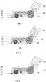
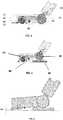
Fig. 1 shows a typical architecture of a battery operated floor cleaning device;Fig. 2 shows the floor cleaning device ofFig. 1 with a squeegee;Fig. 3 shows the airflow in the floor cleaning device ofFig. 1 ;Fig. 4 shows the airflow in the floor cleaning device ofFig. 2 ;Fig. 5 shows a floor cleaning device provided with a mopping element in accordance with an embodiment of the invention;Fig. 6 shows a brush offset as an impact of lifting the rear wheels in the floor cleaning device in accordance with an embodiment of the invention;Fig. 7 shows an angular offset as an impact of lifting the rear wheels in the floor cleaning device in accordance with an embodiment of the invention;Fig. 8 shows the impact of lifting the rear wheels on the performance on cleaning the crevices;Fig. 9 shows a top view of the floor cleaning device ofFig. 5 ;Figs. 10 and 11 show an embodiment of a floor cleaning device in which the squeegee can shift down when the rear end of the appliance is lifted; andFig. 12 shows another embodiment of the invention with the front wheels formed at the ends of the suction channel- To have a good cleaning performance with low suction power < 30 W (mains connected appliances use in general >100 W suction power (current state of art)), agitation of the dust or agitation of the piles of the carpets is necessary. Therefore all common known battery operated appliances are equipped with a rotating brush for agitating the dust/piles. The typical architecture of a battery operated appliance is shown in
Fig. 1 , which illustrateshousing 10,housing stick 20, drivemotor rotating brush 30,rear wheel 40,airflow channel 50, rotatingbrush 60, andfront wheel 70. However, it will be appreciated by a person skilled in the art that the battery-operated appliance can be replaced by an appliance which has no batteries and is operated via mains, or by an appliance which is operated via a combination of battery and mains. Further, the appliance may have a non powered brush / passive brush or no brush at all. Furthermore, in case of a powered brush, the brush can be powered using an air turbine or an electric motor either internal or external to the powered brush casing. - By in-depth study of user behavior, we know that coarse dirt is approached from the front of the appliance. Especially, when the wheels on the nozzle are clearly visible. Referring to
Figs. 2, 3 , and4 , by placing asqueegee 80 behind the rotatingbrush 60 the airflow is much more efficient to pick up the dirt. - The appliance with rotating brush and squeegee is able to clean hard and soft floors to an acceptable level.
- To make the appliance a hybrid appliance so that hard floors can also be wet cleaned, a mopping element can be added. Because the mopping action is almost simultaneous with the vacuum action, the mop remains clean for a longer period than when performing the vacuum and mopping actions sequentially.
- Another additional advantage of using a battery operated appliance and the associated low suction power is that the water which is distributed to the floor by the mopping element is not sucked back up by the suction nozzle. This prevents that the dirt/air separation can be done on the traditional manner without having precautions for water intake. Thus, this eliminates the task of having a expensive water filtration module within the device and makes the device economical.
- The three obvious positions to place a mopping element (in front, at the rear or in between wheels and squeegee) will result in an appliance which will get dirty quickly. The brush, squeegee and wheels touch the floor and pick up liquid and wet dirt during usage.
- Referring now to
Fig. 5 , to protectsqueegee 80 andbrush 60 from polluting, in accordance with an aspect of the invention, moppingelement 90 is placed underneath therear wheels 40. The whole system is than tilted a bit, and the squeegee and brush are also lifted from the floor a little. Further, the front end of the nozzle, with or without the wheels, continues to touch the floor as before and is not lifted. Thus, an optimum suction is still maintained and the suction boundaries are formed by the front wheel and therear squeegee 80 and moppingelement 90. Even when for stubborn stains, the appliance is moved several times back and forwards, the brush and squeegee remain clean. It will be appreciated that the squeegee will be lifted in such a manner that it maintains minimal air gap with the floor and thus ensures an optimum suction efficiency. - If the rear wheels are lifted just a little, the performance drop due to lifting the brush and squeegee is very limited. The brush offset BO and lifting of the appliance by angle α can be seen in
Figs. 6 and7 , respectively. The bigger coarse dirt is still touched by the brush and the airflow is still directed to the front. The graph ofFig. 8 shows the impact of lifting on the performance on cleaning crevices (most difficult to clean area of the floors) at two different voltages, i.e. 18 V and 14.4 V respectively: the higher the distance from the floor (horizontal axis), the lower the dirt pick-up percentage DPU (vertical axis). Further, it can be inferred from the graph ofFig. 8 that the performance or percentage DPU drops below 30% when the brush offset BO is more than 1.2 mm. It has been revealed from user studies that a percentage DPU of below 30% is well detected by the user as the user is able to notice a drop in performance / suction and visible cleanliness. Therefore, the brush offset BO will always be kept above 30% DPU levels or between 0 - 1.2 mm. The two different voltages used to plot the graph correspond to two different upright suction cleaners that were used for testing. It will be appreciated that given a higher voltage rating a higher suction power can be achieved and the brush offset can be even more without undue decrease in DPU and performance i.e. a DPU of 30% and more can be attained with a significant brush offset as compared to the range mentioned above. - The brush offset can be translated into an angular relation that the mopping device makes with the surface to be cleaned, e.g. the floor. The brush offset BO mentioned above can be achieved by angularly rotating in the XY plane the imaginary axis of the front wheels between a range of 0 degrees and 15 degrees both including as shown in
Fig. 7 . These aforementioned design principles can be adopted to achieve optimum percentage DPU in the device along with good mopping performance. - As shown in
Fig. 12 , in another embodiment of this invention, the wheels are not present in the front but placed along the suction channel/opening. In this embodiment, when the mopping accessory is placed underneath the rear wheels and the appliance will be lifted then the angle alpha will have very little effect on the suction performance as the suction channel will be closer to the floor then the previous embodiment for the fact that the wheels will be touching the floor and the suction channel is formed between the wheels. - When the mopping element is placed closely to the squeegee it also reduces air leakage to the rear due to the lifting of the squeegee.
- By placing the mopping element underneath the wheels, there is also a place created to put small reservoirs on the mopping element beside the wheels.
- The architecture of a battery operated nozzle is depicted in
Fig. 9 (top view), showinghousing 10,wheels 40, moppingelement 90, andreservoirs 100. - By adding a suitable water transport mechanism (e.g. small holes or wick as described in co-pending
US application 62/065950 reservoirs 100 and the mopping element, a wet mopping function can be achieved. Further, the cleaning performance overtime is limited by the volume of the reservoir and no longer limited to the amount of water that can be held in the cloth or wipe underneath the mopping element. - It also means that the wetness of the floor does no longer depend on the way it is used by the user. The performance is therefore much more guaranteed and is stable during usage (cloth does not dry out).
- The surface area that can be cleaned is only limited by the volume of the reservoir. A wetness of the floor of approximately 2 gr/m2 means that for cleaning an average house of 100 m2 hard floors, a reservoir of 200 ml is sufficient. If the cloth is e.g. 5 cm x 30 cm, the height of the reservoir can be less than 1.5 cm.
- Because the mopping element contains the reservoirs and the cloth it can be easily be placed and detached from the appliance without making an interface for connecting wet elements. This also means that a hybrid appliance can be built by using the standard architecture of a battery operated vacuum appliance.
- A simple interface between the mopping element that contains all the "wet:" parts and the vacuum nozzle can be done on numerous ways. A good and simple way which is very appreciated by users is a connection by magnets.
- Referring to
Figs. 10 and 11 , the reduction in performance of dirt pick up due to lifting the appliance can be reduced by a simple mechanism that the squeegee is fixated in such a manner that it can shift down when the rear end of the appliance is lifted.Fig. 10 shows a normal width of a gap G, whileFig. 11 shows a reduced width of gap G, resulting from a spring that pushes the squeegee downwards. Such a function can be achieved in numerous ways and one example can be by using springs which lowers the squeegee when it is lifted. Also, as mentioned above it will be ensured that the squeegee maintains a minimal air gap when lifted. - It should be noted that the above-mentioned embodiments illustrate rather than limit the invention, and that those skilled in the art will be able to design many alternative embodiments without departing from the scope of the appended claims. In the claims, any reference signs placed between parentheses shall not be construed as limiting the claim. The word "comprising" does not exclude the presence of elements or steps other than those listed in a claim. The word "a" or "an" preceding an element does not exclude the presence of a plurality of such elements. The mere fact that certain measures are recited in mutually different dependent claims does not indicate that a combination of these measures cannot be used to advantage.
Claims (5)
- A nozzle (10) for a floor cleaning device, suitable for both wet and dry cleaning, the nozzle comprising:an airflow inlet (50) at a front end of the nozzle,a rear wheel (40) at a rear end of the nozzle (10), andcharacterized bya detachable wet cleaning device (90) that, if mounted underneath the rear wheel (40) of the nozzle (10), lifts a rear end of the nozzle, wherein the detachable wet cleaning device (90) is arranged for being provided with a removable mopping substrate, wherein the detachable wet cleaning device (90) has a liquid container (100) for containing a liquid for wetting the removable mopping substrate.
- A nozzle as claimed in claim 1, wherein the nozzle has a squeegee (80) that reaches substantially close to a surface to be cleaned with the detachable cleaning device being attached to the nozzle.
- A nozzle as claimed in any of the preceding claims, further comprising a rotating brush (60) in said airflow inlet (50), which rotating brush (60) is lifted from a surface to be cleaned as a result of mounting the detachable wet cleaning device (90), wherein an offset between said rotating brush (60) and the surface is less than 1.2 mm in the presence of the detachable cleaning device (90).
- A floor cleaning device, comprising a nozzle as claimed in any of the preceding claims, and an air pump connectable to the nozzle.
- A floor cleaning device as claimed in claim 4, which is battery-operated.
Priority Applications (10)
| Application Number | Priority Date | Filing Date | Title |
|---|---|---|---|
| PL15153559TPL3011883T3 (en) | 2014-10-20 | 2015-02-03 | Floor cleaning device |
| PL16194444TPL3150096T3 (en) | 2014-10-20 | 2015-02-03 | Floor cleaning device |
| EP16194444.2AEP3150096B1 (en) | 2014-10-20 | 2015-02-03 | Floor cleaning device |
| JP2015066964AJP6974929B2 (en) | 2014-10-20 | 2015-03-27 | Floor cleaning device |
| RU2016147952ARU2655197C1 (en) | 2014-10-20 | 2015-10-19 | Device for cleaning floors |
| US15/322,472US9955835B2 (en) | 2014-10-20 | 2015-10-19 | Floor cleaning device |
| PCT/EP2015/074094WO2016062647A1 (en) | 2014-10-20 | 2015-10-19 | Floor cleaning device |
| CN201580026090.4ACN106455880B (en) | 2014-10-20 | 2015-10-19 | Floor cleaning |
| DE212015000249.7UDE212015000249U1 (en) | 2014-10-20 | 2015-10-19 | Floor cleaning device |
| KR1020177012207AKR101814192B1 (en) | 2014-10-20 | 2015-10-19 | Floor cleaning device |
Applications Claiming Priority (2)
| Application Number | Priority Date | Filing Date | Title |
|---|---|---|---|
| US201462065946P | 2014-10-20 | 2014-10-20 | |
| US201462066493P | 2014-10-21 | 2014-10-21 |
Related Child Applications (2)
| Application Number | Title | Priority Date | Filing Date |
|---|---|---|---|
| EP16194444.2ADivisionEP3150096B1 (en) | 2014-10-20 | 2015-02-03 | Floor cleaning device |
| EP16194444.2ADivision-IntoEP3150096B1 (en) | 2014-10-20 | 2015-02-03 | Floor cleaning device |
Publications (2)
| Publication Number | Publication Date |
|---|---|
| EP3011883A1 EP3011883A1 (en) | 2016-04-27 |
| EP3011883B1true EP3011883B1 (en) | 2019-04-24 |
Family
ID=52464183
Family Applications (2)
| Application Number | Title | Priority Date | Filing Date |
|---|---|---|---|
| EP15153559.8AActiveEP3011883B1 (en) | 2014-10-20 | 2015-02-03 | Floor cleaning device |
| EP16194444.2AActiveEP3150096B1 (en) | 2014-10-20 | 2015-02-03 | Floor cleaning device |
Family Applications After (1)
| Application Number | Title | Priority Date | Filing Date |
|---|---|---|---|
| EP16194444.2AActiveEP3150096B1 (en) | 2014-10-20 | 2015-02-03 | Floor cleaning device |
Country Status (9)
| Country | Link |
|---|---|
| US (1) | US9955835B2 (en) |
| EP (2) | EP3011883B1 (en) |
| JP (1) | JP6974929B2 (en) |
| KR (1) | KR101814192B1 (en) |
| CN (1) | CN106455880B (en) |
| DE (1) | DE212015000249U1 (en) |
| PL (2) | PL3011883T3 (en) |
| RU (1) | RU2655197C1 (en) |
| WO (1) | WO2016062647A1 (en) |
Families Citing this family (33)
| Publication number | Priority date | Publication date | Assignee | Title |
|---|---|---|---|---|
| CN110049705A (en)* | 2016-10-14 | 2019-07-23 | 尚科宁家运营有限公司 | Vacuum cleaner with air agitation auxiliary |
| US11426038B2 (en) | 2017-09-11 | 2022-08-30 | Sharkninja Operating Llc | Cleaning device |
| JP2020533028A (en) | 2017-09-11 | 2020-11-19 | シャークニンジャ オペレーティング エルエルシー | Cleaning device |
| EP3536209A1 (en)* | 2018-03-05 | 2019-09-11 | Koninklijke Philips N.V. | Vacuum cleaner nozzle |
| DE102018115669A1 (en)* | 2018-06-28 | 2020-01-02 | Vorwerk & Co. Interholding Gmbh | Soil cultivation device with a basic device and a front device that can be detachably connected to the basic device |
| CA3118015A1 (en) | 2018-11-01 | 2020-05-07 | Sharkninja Operating Llc | Cleaning device |
| CN215605351U (en) | 2018-12-18 | 2022-01-25 | 尚科宁家运营有限公司 | Cleaning device replacement head |
| US11426044B1 (en) | 2018-12-18 | 2022-08-30 | Sharkninja Operating Llc | Cleaning device |
| EP3897330B1 (en) | 2018-12-21 | 2023-09-06 | Tennant Company | Sweeper/scrubber system capable of handling large debris |
| CN111820812B (en)* | 2019-04-15 | 2025-07-25 | 苏州德莱电器有限公司 | Surface cleaning head for vacuum cleaner |
| CN111820810B (en)* | 2019-04-15 | 2025-07-25 | 苏州德莱电器有限公司 | Surface cleaning head for vacuum cleaner |
| EP4009844A4 (en) | 2019-08-08 | 2023-09-06 | SharkNinja Operating LLC | CLEANING ROBOT WITH AIR NOZZLE ARRANGEMENT |
| US20230248192A1 (en)* | 2019-08-08 | 2023-08-10 | Sharkninja Operating Llc | Robotic cleaner with air jet assembly |
| CN110353565A (en)* | 2019-08-14 | 2019-10-22 | 小狗电器互联网科技(北京)股份有限公司 | A kind of cistern assembly and scrubbing brush |
| CN110547725B (en)* | 2019-09-18 | 2024-05-03 | 北京小狗吸尘器集团股份有限公司 | Water tank, cleaning head and dust collector for floor brush |
| GB2588155B (en)* | 2019-10-10 | 2021-12-22 | Dyson Technology Ltd | Cleaner head for a vacuum cleaning appliance |
| CN112716353B (en)* | 2019-10-14 | 2025-07-15 | 苏州爱普电器有限公司 | Surface cleaning heads for vacuum cleaners |
| US11452414B2 (en) | 2019-10-31 | 2022-09-27 | Sharkninja Operating Llc | Replacement head for a vacuum |
| US11219345B2 (en) | 2019-10-31 | 2022-01-11 | Sharkninja Operating Llc | Replacement head for a vacuum |
| US11266283B2 (en) | 2019-10-31 | 2022-03-08 | Sharkninja Operating Llc | Replacement head for a vacuum |
| US10959584B1 (en) | 2019-10-31 | 2021-03-30 | Sharkninja Operating Llc | Replacement head for a vacuum |
| US11471019B2 (en) | 2020-02-14 | 2022-10-18 | Sharkninja Operating Llc | Cleaning device with lights |
| USD946226S1 (en) | 2020-02-14 | 2022-03-15 | Sharkninja Operating Llc | Cleaning device |
| USD946843S1 (en) | 2020-02-14 | 2022-03-22 | Sharkninja Operating Llc | Cleaning device |
| USD946842S1 (en) | 2020-02-14 | 2022-03-22 | Sharkninja Operating Llc | Cleaning device |
| USD946223S1 (en) | 2020-02-14 | 2022-03-15 | Sharkninja Operating Llc | Cleaning device |
| US10952580B1 (en) | 2020-02-19 | 2021-03-23 | Sharkninja Operating Llc | Cleaning device with rotatable head |
| US11179014B2 (en) | 2020-02-19 | 2021-11-23 | Sharkninja Operating Llc | Cleaning device system and method for use |
| KR200494847Y1 (en)* | 2020-07-10 | 2022-01-07 | 지홍용 | Escalator step cleaning tool |
| JP7145527B2 (en)* | 2020-10-28 | 2022-10-03 | アイリスオーヤマ株式会社 | vacuum cleaner |
| US12399501B2 (en)* | 2020-12-10 | 2025-08-26 | AI Incorporated | Method of lightweight simultaneous localization and mapping performed on a real-time computing and battery operated wheeled device |
| DE202022002747U1 (en) | 2022-09-14 | 2024-01-18 | Wessel-Werk Gmbh | Vacuum cleaner nozzle and cleaning arrangement |
| DE202022105982U1 (en) | 2022-10-24 | 2022-11-07 | Excellent Market Ltd. | Nozzle for a vacuum cleaner |
Family Cites Families (26)
| Publication number | Priority date | Publication date | Assignee | Title |
|---|---|---|---|---|
| JPH0687836B2 (en)* | 1991-11-14 | 1994-11-09 | 三星電子株式会社 | Wet-dry vacuum cleaner |
| JPH1014829A (en)* | 1996-07-09 | 1998-01-20 | Sanyo Electric Co Ltd | Suction tool for electric vacuum cleaner |
| JPH1057283A (en)* | 1996-08-19 | 1998-03-03 | Sanyo Electric Co Ltd | Suction tool for vacuum cleaner |
| US7013528B2 (en)* | 2002-01-28 | 2006-03-21 | Bissell Homecare, Inc. | Floor cleaner with dusting |
| US20040134016A1 (en)* | 2003-01-10 | 2004-07-15 | Royal Appliance Manufacturing Company | Suction wet jet mop |
| US7137169B2 (en)* | 2003-01-10 | 2006-11-21 | Royal Appliance Mfg. Co. | Vacuum cleaner with cleaning pad |
| US6966098B2 (en)* | 2003-02-27 | 2005-11-22 | Matsushita Electric Industrial Co., Ltd. | Cleaner |
| JP2004350826A (en)* | 2003-05-28 | 2004-12-16 | Matsushita Electric Ind Co Ltd | Electric vacuum cleaner |
| JP2006102052A (en)* | 2004-10-04 | 2006-04-20 | Sanyo Electric Co Ltd | Suction tool of vacuum cleaner |
| KR101240732B1 (en) | 2005-02-18 | 2013-03-07 | 아이로보트 코퍼레이션 | Autonomous surface cleaning robot for wet and dry cleaning |
| JP3128923U (en)* | 2006-10-25 | 2007-02-01 | ミサエ 増田 | mop |
| KR101218445B1 (en)* | 2006-12-29 | 2013-01-04 | 엘지전자 주식회사 | Steam generator and vacuum cleaner using same |
| AU2008200975B2 (en) | 2007-03-05 | 2012-09-27 | Bissell Inc. | Accessory tool for a vacuum cleaner |
| DE102007022256B4 (en)* | 2007-05-09 | 2013-07-25 | Miele & Cie. Kg | Nozzle for a floor care appliance |
| DE102008012889B4 (en)* | 2008-03-06 | 2012-04-19 | Wessel-Werk Gmbh | Suction nozzle for vacuum cleaner |
| CN104248395B (en)* | 2008-04-24 | 2018-06-22 | 艾罗伯特公司 | The positioning of mobile product, position control and the application of navigation system enabled for robot |
| US8961695B2 (en)* | 2008-04-24 | 2015-02-24 | Irobot Corporation | Mobile robot for cleaning |
| US7934287B2 (en)* | 2008-07-31 | 2011-05-03 | The Procter & Gamble Company | Head for a cleaning implement having a removable dirt bin |
| EP2250957B1 (en) | 2009-05-12 | 2014-07-02 | Bissell Homecare, Inc. | Upright steam mop sweeper |
| KR20110047532A (en)* | 2009-10-30 | 2011-05-09 | 엘지전자 주식회사 | Vacuum cleaner with detergent spray nozzle |
| CN202036151U (en)* | 2010-09-27 | 2011-11-16 | 马卫宏 | Suction nozzle of vacuum dust collector |
| AU2011253852B2 (en)* | 2010-12-15 | 2014-06-05 | Bissell Inc. | Suction nozzle with shuttling plate and converging debris paths |
| KR20120129190A (en)* | 2011-05-19 | 2012-11-28 | 어수곤 | robot cleaner |
| KR101443648B1 (en)* | 2012-12-27 | 2014-09-23 | 엘지전자 주식회사 | vacuum cleaner |
| US9867418B2 (en) | 2014-03-31 | 2018-01-16 | Pairme Products, Llc | Shoe pair with position indicator assembly |
| EP3011885B1 (en) | 2014-10-20 | 2019-04-24 | Koninklijke Philips N.V. | Floor cleaning device |
- 2015
- 2015-02-03EPEP15153559.8Apatent/EP3011883B1/enactiveActive
- 2015-02-03PLPL15153559Tpatent/PL3011883T3/enunknown
- 2015-02-03PLPL16194444Tpatent/PL3150096T3/enunknown
- 2015-02-03EPEP16194444.2Apatent/EP3150096B1/enactiveActive
- 2015-03-27JPJP2015066964Apatent/JP6974929B2/enactiveActive
- 2015-10-19USUS15/322,472patent/US9955835B2/enactiveActive
- 2015-10-19RURU2016147952Apatent/RU2655197C1/enactive
- 2015-10-19WOPCT/EP2015/074094patent/WO2016062647A1/enactiveApplication Filing
- 2015-10-19KRKR1020177012207Apatent/KR101814192B1/enactiveActive
- 2015-10-19DEDE212015000249.7Upatent/DE212015000249U1/enactiveActive
- 2015-10-19CNCN201580026090.4Apatent/CN106455880B/ennot_activeExpired - Fee Related
Non-Patent Citations (1)
| Title |
|---|
| None* |
Also Published As
| Publication number | Publication date |
|---|---|
| CN106455880B (en) | 2018-05-22 |
| JP2016077867A (en) | 2016-05-16 |
| US20170215668A1 (en) | 2017-08-03 |
| JP6974929B2 (en) | 2021-12-01 |
| EP3150096B1 (en) | 2018-09-26 |
| CN106455880A (en) | 2017-02-22 |
| KR20170063945A (en) | 2017-06-08 |
| PL3150096T3 (en) | 2019-03-29 |
| US9955835B2 (en) | 2018-05-01 |
| DE212015000249U1 (en) | 2017-07-21 |
| EP3150096A1 (en) | 2017-04-05 |
| KR101814192B1 (en) | 2018-01-30 |
| EP3011883A1 (en) | 2016-04-27 |
| RU2655197C1 (en) | 2018-05-24 |
| PL3011883T3 (en) | 2019-09-30 |
| WO2016062647A1 (en) | 2016-04-28 |
Similar Documents
| Publication | Publication Date | Title |
|---|---|---|
| EP3011883B1 (en) | Floor cleaning device | |
| CN109316136B (en) | Base station for cleaning robot system | |
| CN109620064B (en) | Base station for cleaning robot system | |
| CN106510556B (en) | Cleaning robots and cleaning robot systems | |
| CN201840416U (en) | Dust collection device for self-propelled vacuum cleaner | |
| US10188250B2 (en) | Floor cleaning tool having a mechanically operated pump | |
| US9301661B2 (en) | Floor cleaning tool having a mechanically operated pump | |
| CN112656319A (en) | Base station and cleaning robot system | |
| CN203468522U (en) | Dust collector | |
| US9877625B2 (en) | Floor cleaning tool having a mechanically operated pump | |
| CN216090328U (en) | Handheld cleaning device | |
| US9877624B2 (en) | Floor cleaning tool having a mechanically operated pump | |
| EP3206546B1 (en) | Floor scrubbing machine | |
| CN210612059U (en) | Hand-held type mopping dust absorption all-in-one | |
| CN211432732U (en) | Water-spraying floor-wiping dust-absorbing integrated floor brush device | |
| CN202553808U (en) | Multifunctional dust suction cleaner | |
| CN209360561U (en) | A kind of floor brush of duster floor mop structure | |
| KR20090008966U (en) | Vacuum cleaner suction device | |
| CN115474866A (en) | Surface cleaning robot with sweep and drag multi-functionally | |
| CN201451570U (en) | Electrostatic vacuum slippers | |
| CN204862966U (en) | Novel multi -functional dust catcher | |
| HK40003898A (en) | Base station for cleaning robot system | |
| HK1204897B (en) | Floor cleaning tool having a mechanically operated pump |
Legal Events
| Date | Code | Title | Description |
|---|---|---|---|
| PUAI | Public reference made under article 153(3) epc to a published international application that has entered the european phase | Free format text:ORIGINAL CODE: 0009012 | |
| AK | Designated contracting states | Kind code of ref document:A1 Designated state(s):AL AT BE BG CH CY CZ DE DK EE ES FI FR GB GR HR HU IE IS IT LI LT LU LV MC MK MT NL NO PL PT RO RS SE SI SK SM TR | |
| AX | Request for extension of the european patent | Extension state:BA ME | |
| STAA | Information on the status of an ep patent application or granted ep patent | Free format text:STATUS: REQUEST FOR EXAMINATION WAS MADE | |
| 17P | Request for examination filed | Effective date:20161027 | |
| RBV | Designated contracting states (corrected) | Designated state(s):AL AT BE BG CH CY CZ DE DK EE ES FI FR GB GR HR HU IE IS IT LI LT LU LV MC MK MT NL NO PL PT RO RS SE SI SK SM TR | |
| GRAP | Despatch of communication of intention to grant a patent | Free format text:ORIGINAL CODE: EPIDOSNIGR1 | |
| STAA | Information on the status of an ep patent application or granted ep patent | Free format text:STATUS: GRANT OF PATENT IS INTENDED | |
| INTG | Intention to grant announced | Effective date:20181109 | |
| GRAS | Grant fee paid | Free format text:ORIGINAL CODE: EPIDOSNIGR3 | |
| GRAA | (expected) grant | Free format text:ORIGINAL CODE: 0009210 | |
| STAA | Information on the status of an ep patent application or granted ep patent | Free format text:STATUS: THE PATENT HAS BEEN GRANTED | |
| AK | Designated contracting states | Kind code of ref document:B1 Designated state(s):AL AT BE BG CH CY CZ DE DK EE ES FI FR GB GR HR HU IE IS IT LI LT LU LV MC MK MT NL NO PL PT RO RS SE SI SK SM TR | |
| REG | Reference to a national code | Ref country code:GB Ref legal event code:FG4D | |
| REG | Reference to a national code | Ref country code:CH Ref legal event code:EP | |
| REG | Reference to a national code | Ref country code:AT Ref legal event code:REF Ref document number:1123108 Country of ref document:AT Kind code of ref document:T Effective date:20190515 Ref country code:IE Ref legal event code:FG4D | |
| REG | Reference to a national code | Ref country code:DE Ref legal event code:R096 Ref document number:602015028703 Country of ref document:DE | |
| REG | Reference to a national code | Ref country code:NL Ref legal event code:FP | |
| REG | Reference to a national code | Ref country code:LT Ref legal event code:MG4D | |
| PG25 | Lapsed in a contracting state [announced via postgrant information from national office to epo] | Ref country code:HR Free format text:LAPSE BECAUSE OF FAILURE TO SUBMIT A TRANSLATION OF THE DESCRIPTION OR TO PAY THE FEE WITHIN THE PRESCRIBED TIME-LIMIT Effective date:20190424 Ref country code:SE Free format text:LAPSE BECAUSE OF FAILURE TO SUBMIT A TRANSLATION OF THE DESCRIPTION OR TO PAY THE FEE WITHIN THE PRESCRIBED TIME-LIMIT Effective date:20190424 Ref country code:ES Free format text:LAPSE BECAUSE OF FAILURE TO SUBMIT A TRANSLATION OF THE DESCRIPTION OR TO PAY THE FEE WITHIN THE PRESCRIBED TIME-LIMIT Effective date:20190424 Ref country code:LT Free format text:LAPSE BECAUSE OF FAILURE TO SUBMIT A TRANSLATION OF THE DESCRIPTION OR TO PAY THE FEE WITHIN THE PRESCRIBED TIME-LIMIT Effective date:20190424 Ref country code:NO Free format text:LAPSE BECAUSE OF FAILURE TO SUBMIT A TRANSLATION OF THE DESCRIPTION OR TO PAY THE FEE WITHIN THE PRESCRIBED TIME-LIMIT Effective date:20190724 Ref country code:AL Free format text:LAPSE BECAUSE OF FAILURE TO SUBMIT A TRANSLATION OF THE DESCRIPTION OR TO PAY THE FEE WITHIN THE PRESCRIBED TIME-LIMIT Effective date:20190424 Ref country code:PT Free format text:LAPSE BECAUSE OF FAILURE TO SUBMIT A TRANSLATION OF THE DESCRIPTION OR TO PAY THE FEE WITHIN THE PRESCRIBED TIME-LIMIT Effective date:20190824 Ref country code:FI Free format text:LAPSE BECAUSE OF FAILURE TO SUBMIT A TRANSLATION OF THE DESCRIPTION OR TO PAY THE FEE WITHIN THE PRESCRIBED TIME-LIMIT Effective date:20190424 | |
| PG25 | Lapsed in a contracting state [announced via postgrant information from national office to epo] | Ref country code:BG Free format text:LAPSE BECAUSE OF FAILURE TO SUBMIT A TRANSLATION OF THE DESCRIPTION OR TO PAY THE FEE WITHIN THE PRESCRIBED TIME-LIMIT Effective date:20190724 Ref country code:LV Free format text:LAPSE BECAUSE OF FAILURE TO SUBMIT A TRANSLATION OF THE DESCRIPTION OR TO PAY THE FEE WITHIN THE PRESCRIBED TIME-LIMIT Effective date:20190424 Ref country code:GR Free format text:LAPSE BECAUSE OF FAILURE TO SUBMIT A TRANSLATION OF THE DESCRIPTION OR TO PAY THE FEE WITHIN THE PRESCRIBED TIME-LIMIT Effective date:20190725 Ref country code:RS Free format text:LAPSE BECAUSE OF FAILURE TO SUBMIT A TRANSLATION OF THE DESCRIPTION OR TO PAY THE FEE WITHIN THE PRESCRIBED TIME-LIMIT Effective date:20190424 | |
| REG | Reference to a national code | Ref country code:AT Ref legal event code:MK05 Ref document number:1123108 Country of ref document:AT Kind code of ref document:T Effective date:20190424 | |
| PG25 | Lapsed in a contracting state [announced via postgrant information from national office to epo] | Ref country code:IS Free format text:LAPSE BECAUSE OF FAILURE TO SUBMIT A TRANSLATION OF THE DESCRIPTION OR TO PAY THE FEE WITHIN THE PRESCRIBED TIME-LIMIT Effective date:20190824 | |
| REG | Reference to a national code | Ref country code:DE Ref legal event code:R097 Ref document number:602015028703 Country of ref document:DE | |
| PG25 | Lapsed in a contracting state [announced via postgrant information from national office to epo] | Ref country code:EE Free format text:LAPSE BECAUSE OF FAILURE TO SUBMIT A TRANSLATION OF THE DESCRIPTION OR TO PAY THE FEE WITHIN THE PRESCRIBED TIME-LIMIT Effective date:20190424 Ref country code:SK Free format text:LAPSE BECAUSE OF FAILURE TO SUBMIT A TRANSLATION OF THE DESCRIPTION OR TO PAY THE FEE WITHIN THE PRESCRIBED TIME-LIMIT Effective date:20190424 Ref country code:CZ Free format text:LAPSE BECAUSE OF FAILURE TO SUBMIT A TRANSLATION OF THE DESCRIPTION OR TO PAY THE FEE WITHIN THE PRESCRIBED TIME-LIMIT Effective date:20190424 Ref country code:RO Free format text:LAPSE BECAUSE OF FAILURE TO SUBMIT A TRANSLATION OF THE DESCRIPTION OR TO PAY THE FEE WITHIN THE PRESCRIBED TIME-LIMIT Effective date:20190424 Ref country code:DK Free format text:LAPSE BECAUSE OF FAILURE TO SUBMIT A TRANSLATION OF THE DESCRIPTION OR TO PAY THE FEE WITHIN THE PRESCRIBED TIME-LIMIT Effective date:20190424 Ref country code:AT Free format text:LAPSE BECAUSE OF FAILURE TO SUBMIT A TRANSLATION OF THE DESCRIPTION OR TO PAY THE FEE WITHIN THE PRESCRIBED TIME-LIMIT Effective date:20190424 | |
| PG25 | Lapsed in a contracting state [announced via postgrant information from national office to epo] | Ref country code:SM Free format text:LAPSE BECAUSE OF FAILURE TO SUBMIT A TRANSLATION OF THE DESCRIPTION OR TO PAY THE FEE WITHIN THE PRESCRIBED TIME-LIMIT Effective date:20190424 Ref country code:IT Free format text:LAPSE BECAUSE OF FAILURE TO SUBMIT A TRANSLATION OF THE DESCRIPTION OR TO PAY THE FEE WITHIN THE PRESCRIBED TIME-LIMIT Effective date:20190424 | |
| PLBE | No opposition filed within time limit | Free format text:ORIGINAL CODE: 0009261 | |
| STAA | Information on the status of an ep patent application or granted ep patent | Free format text:STATUS: NO OPPOSITION FILED WITHIN TIME LIMIT | |
| RAP2 | Party data changed (patent owner data changed or rights of a patent transferred) | Owner name:KONINKLIJKE PHILIPS N.V. | |
| 26N | No opposition filed | Effective date:20200127 | |
| PG25 | Lapsed in a contracting state [announced via postgrant information from national office to epo] | Ref country code:SI Free format text:LAPSE BECAUSE OF FAILURE TO SUBMIT A TRANSLATION OF THE DESCRIPTION OR TO PAY THE FEE WITHIN THE PRESCRIBED TIME-LIMIT Effective date:20190424 | |
| REG | Reference to a national code | Ref country code:CH Ref legal event code:PL | |
| REG | Reference to a national code | Ref country code:BE Ref legal event code:MM Effective date:20200229 | |
| PG25 | Lapsed in a contracting state [announced via postgrant information from national office to epo] | Ref country code:MC Free format text:LAPSE BECAUSE OF FAILURE TO SUBMIT A TRANSLATION OF THE DESCRIPTION OR TO PAY THE FEE WITHIN THE PRESCRIBED TIME-LIMIT Effective date:20190424 Ref country code:LU Free format text:LAPSE BECAUSE OF NON-PAYMENT OF DUE FEES Effective date:20200203 | |
| PG25 | Lapsed in a contracting state [announced via postgrant information from national office to epo] | Ref country code:CH Free format text:LAPSE BECAUSE OF NON-PAYMENT OF DUE FEES Effective date:20200229 Ref country code:LI Free format text:LAPSE BECAUSE OF NON-PAYMENT OF DUE FEES Effective date:20200229 | |
| PG25 | Lapsed in a contracting state [announced via postgrant information from national office to epo] | Ref country code:IE Free format text:LAPSE BECAUSE OF NON-PAYMENT OF DUE FEES Effective date:20200203 | |
| PG25 | Lapsed in a contracting state [announced via postgrant information from national office to epo] | Ref country code:BE Free format text:LAPSE BECAUSE OF NON-PAYMENT OF DUE FEES Effective date:20200229 | |
| PG25 | Lapsed in a contracting state [announced via postgrant information from national office to epo] | Ref country code:MT Free format text:LAPSE BECAUSE OF FAILURE TO SUBMIT A TRANSLATION OF THE DESCRIPTION OR TO PAY THE FEE WITHIN THE PRESCRIBED TIME-LIMIT Effective date:20190424 Ref country code:CY Free format text:LAPSE BECAUSE OF FAILURE TO SUBMIT A TRANSLATION OF THE DESCRIPTION OR TO PAY THE FEE WITHIN THE PRESCRIBED TIME-LIMIT Effective date:20190424 | |
| PG25 | Lapsed in a contracting state [announced via postgrant information from national office to epo] | Ref country code:MK Free format text:LAPSE BECAUSE OF FAILURE TO SUBMIT A TRANSLATION OF THE DESCRIPTION OR TO PAY THE FEE WITHIN THE PRESCRIBED TIME-LIMIT Effective date:20190424 | |
| P01 | Opt-out of the competence of the unified patent court (upc) registered | Effective date:20230530 | |
| REG | Reference to a national code | Ref country code:NL Ref legal event code:PD Owner name:VERSUNI HOLDING B.V.; NL Free format text:DETAILS ASSIGNMENT: CHANGE OF OWNER(S), ASSIGNMENT; FORMER OWNER NAME: KONINKLIJKE PHILIPS N.V. Effective date:20231108 | |
| REG | Reference to a national code | Ref country code:DE Ref legal event code:R081 Ref document number:602015028703 Country of ref document:DE Owner name:VERSUNI HOLDING B.V., NL Free format text:FORMER OWNER: KONINKLIJKE PHILIPS N.V., EINDHOVEN, NL | |
| REG | Reference to a national code | Ref country code:GB Ref legal event code:732E Free format text:REGISTERED BETWEEN 20231214 AND 20231220 | |
| PGFP | Annual fee paid to national office [announced via postgrant information from national office to epo] | Ref country code:NL Payment date:20250224 Year of fee payment:11 | |
| PGFP | Annual fee paid to national office [announced via postgrant information from national office to epo] | Ref country code:DE Payment date:20250226 Year of fee payment:11 | |
| PGFP | Annual fee paid to national office [announced via postgrant information from national office to epo] | Ref country code:FR Payment date:20250224 Year of fee payment:11 Ref country code:PL Payment date:20250121 Year of fee payment:11 | |
| PGFP | Annual fee paid to national office [announced via postgrant information from national office to epo] | Ref country code:GB Payment date:20250218 Year of fee payment:11 | |
| PGFP | Annual fee paid to national office [announced via postgrant information from national office to epo] | Ref country code:TR Payment date:20250122 Year of fee payment:11 |