EP3010816B1 - Rfid tag and method of securing same to object - Google Patents
Rfid tag and method of securing same to objectDownload PDFInfo
- Publication number
- EP3010816B1 EP3010816B1EP14813178.2AEP14813178AEP3010816B1EP 3010816 B1EP3010816 B1EP 3010816B1EP 14813178 AEP14813178 AEP 14813178AEP 3010816 B1EP3010816 B1EP 3010816B1
- Authority
- EP
- European Patent Office
- Prior art keywords
- rfid tag
- boss
- protrusions
- rfid
- substrate
- Prior art date
- Legal status (The legal status is an assumption and is not a legal conclusion. Google has not performed a legal analysis and makes no representation as to the accuracy of the status listed.)
- Active
Links
Images


Classifications
- G—PHYSICS
- G06—COMPUTING OR CALCULATING; COUNTING
- G06K—GRAPHICAL DATA READING; PRESENTATION OF DATA; RECORD CARRIERS; HANDLING RECORD CARRIERS
- G06K19/00—Record carriers for use with machines and with at least a part designed to carry digital markings
- G06K19/06—Record carriers for use with machines and with at least a part designed to carry digital markings characterised by the kind of the digital marking, e.g. shape, nature, code
- G06K19/067—Record carriers with conductive marks, printed circuits or semiconductor circuit elements, e.g. credit or identity cards also with resonating or responding marks without active components
- G06K19/07—Record carriers with conductive marks, printed circuits or semiconductor circuit elements, e.g. credit or identity cards also with resonating or responding marks without active components with integrated circuit chips
- G06K19/077—Constructional details, e.g. mounting of circuits in the carrier
- G06K19/07749—Constructional details, e.g. mounting of circuits in the carrier the record carrier being capable of non-contact communication, e.g. constructional details of the antenna of a non-contact smart card
- G06K19/07758—Constructional details, e.g. mounting of circuits in the carrier the record carrier being capable of non-contact communication, e.g. constructional details of the antenna of a non-contact smart card arrangements for adhering the record carrier to further objects or living beings, functioning as an identification tag
- B—PERFORMING OPERATIONS; TRANSPORTING
- B65—CONVEYING; PACKING; STORING; HANDLING THIN OR FILAMENTARY MATERIAL
- B65D—CONTAINERS FOR STORAGE OR TRANSPORT OF ARTICLES OR MATERIALS, e.g. BAGS, BARRELS, BOTTLES, BOXES, CANS, CARTONS, CRATES, DRUMS, JARS, TANKS, HOPPERS, FORWARDING CONTAINERS; ACCESSORIES, CLOSURES, OR FITTINGS THEREFOR; PACKAGING ELEMENTS; PACKAGES
- B65D25/00—Details of other kinds or types of rigid or semi-rigid containers
- B65D25/20—External fittings
- B65D25/205—Means for the attachment of labels, cards, coupons or the like
- G—PHYSICS
- G06—COMPUTING OR CALCULATING; COUNTING
- G06K—GRAPHICAL DATA READING; PRESENTATION OF DATA; RECORD CARRIERS; HANDLING RECORD CARRIERS
- G06K19/00—Record carriers for use with machines and with at least a part designed to carry digital markings
- G06K19/04—Record carriers for use with machines and with at least a part designed to carry digital markings characterised by the shape
- G06K19/041—Constructional details
- G—PHYSICS
- G06—COMPUTING OR CALCULATING; COUNTING
- G06K—GRAPHICAL DATA READING; PRESENTATION OF DATA; RECORD CARRIERS; HANDLING RECORD CARRIERS
- G06K19/00—Record carriers for use with machines and with at least a part designed to carry digital markings
- G06K19/06—Record carriers for use with machines and with at least a part designed to carry digital markings characterised by the kind of the digital marking, e.g. shape, nature, code
- G06K19/067—Record carriers with conductive marks, printed circuits or semiconductor circuit elements, e.g. credit or identity cards also with resonating or responding marks without active components
- G06K19/07—Record carriers with conductive marks, printed circuits or semiconductor circuit elements, e.g. credit or identity cards also with resonating or responding marks without active components with integrated circuit chips
- G06K19/077—Constructional details, e.g. mounting of circuits in the carrier
- G06K19/07749—Constructional details, e.g. mounting of circuits in the carrier the record carrier being capable of non-contact communication, e.g. constructional details of the antenna of a non-contact smart card
- G06K19/07773—Antenna details
- G—PHYSICS
- G06—COMPUTING OR CALCULATING; COUNTING
- G06K—GRAPHICAL DATA READING; PRESENTATION OF DATA; RECORD CARRIERS; HANDLING RECORD CARRIERS
- G06K7/00—Methods or arrangements for sensing record carriers, e.g. for reading patterns
- G06K7/10—Methods or arrangements for sensing record carriers, e.g. for reading patterns by electromagnetic radiation, e.g. optical sensing; by corpuscular radiation
- G06K2007/10504—Data fields affixed to objects or articles
Definitions
- the present inventionrelates to a method and system for securing RFID tags to an object.
- RFID tagsare commonly used to monitor and track a variety of goods.
- RFID tagsmay be secured to and/or formed directly within (e.g., molded within) an object or a storage container. These RFID tags are then programmed with information relating to the object and/or the substance contained within the storage container. The RFID tags may then be scanned during storage and/or transport to obtain the product details.
- the inventionis set out in claims 1 and 8.
- a method for securing an RFID tag to an objectThe RFID tag may include an RFID chip, an antenna electrically connected to the RFID chip, and a first and second opening extending through the RFID tag.
- the methodmay include placing the RFID tag on the object which, in turn, has a first and second protrusion (e.g., integral with the object) extending from the surface of the object.
- the first and second protrusionsmay extend through the first and second openings when the RFID tag is placed on the object.
- the methodmay then melt the first and second protrusions to create a single integral boss that covers at least a portion of the RFID tag and secures the RFID tag to the object.
- melting the protrusionsmay include placing a heated die over the first and second protrusions.
- the methodmay cool the die (or allow the die to cool) so the plastic is below it melting temperature before the die is removed from the part.
- the diemay include a non-stick coating that helps prevent the boss from sticking to the die.
- the RFID tagmay also include a substrate, an adhesive layer located above the substrate, and/or a top layer secured to the substrate via the adhesive layer.
- the RFID chip and antennamay be located on the substrate, and the first and second openings may pass through the substrate.
- the top layermay cover the antenna and RFID chip.
- the RFID tagmay further include a second adhesive layer located on an underside of the substrate.
- the first openingmay be located on a first side of the RFID chip and the second opening may be located on an opposing side of the RFID chip.
- the bossmay cover the RFID chip.
- the RFID tagmay include a third and fourth opening
- the objectmay include a third and fourth protrusion.
- the third and fourth protrusionsmay extend through the third and fourth openings when the RFID tag is placed on the object.
- the methodmay include melting the third and fourth protrusions to create a second single integral boss that covers at least a portion of the RFID tag to secure the RFID tag to the object.
- the second bossmay cover a portion of the antenna.
- the RFID tagmay be non-functional prior to melting the first and second protrusions (and/or the third and fourth protrusions) to create the boss(es), with the resultant electromagnetic properties of the construct enabling the tag's routine functionality.
- a storage containermay include a body defining the structure of the storage container, and first and second protrusions extending from the surface of a part of the storage container.
- An RFID tagmay be secured to the surface of the storage container, and may include a substrate having a first and second opening extending through it.
- the RFID tagmay also include an RFID chip located on the substrate, and an antenna located on the substrate and electrically connected to the RFID chip.
- the first and second openingsmay be configured to receive the first and second protrusions, and the first and second protrusions may be configured to be melted to create a single integral boss covering at least a portion of the RFID tag to secure the RFID tag to the object.
- the first and second protrusionsmay be melted using a heated die that, in turn, may include a non-stick coating that helps prevent the boss from sticking to the die.
- the RFID tagmay also include (1) an adhesive layer located on an underside of the substrate that adheres the RFID tag to the object, (2) a second adhesive layer located above the substrate, and (3) a top layer secured to the substrate via the second adhesive layer. The top layer may cover the antenna and RFID chip.
- the first and second openingsmay be located on opposite sides of the RFID chip so that the boss covers the RFID chip when formed.
- the RFID tagmay include a third and fourth opening
- the storage containermay include a third and fourth protrusion extending from the surface.
- the third and fourth protrusionsmay extend through the third and fourth openings when the RFID tag is placed on the object, and may be melted to create a second single integral boss.
- the second bossmay cover at least a portion of the RFID tag (e.g., a portion of the antenna) to further secure the RFID tag to the object.
- the protrusions(first, second, third and fourth) may be integral with the object, and the RFID tag may be non-functional prior to melting one or more of the protrusions to create the boss.
- an RFID tagmay include a substrate with a pair of openings extending through it.
- the pair of openingsmay be configured to receive a pair of protrusions extending from a surface of an object to which the RFID tag is to be secured.
- the pair of protrusionsmay be configured to be melted (e.g., using a heated die) to create a single integral boss that covers at least a portion of the RFID tag and secures the RFID tag to the object.
- the RFID tagmay also include an RFID chip and an antenna located on the substrate. The antenna may be electrically connected to the RFID chip.
- the diemay include a non-stick coating that prevents the boss from sticking to the die.
- the RFID tagmay include an adhesive layer located on the underside of the substrate to adhere the RFID tag to the object. Additionally or alternatively, the RFID tag may include an adhesive layer located above the substrate, and a top layer secured to the substrate via the adhesive layer. The top layer may cover the antenna and RFID chip.
- the pair of openingsmay include a first opening and a second opening that are located on opposite sides of the RFID chip, such that the boss covers the RFID chip when formed.
- the RFID tagmay also include a second pair of openings configured to receive a second pair of protrusions extending from the surface of the object.
- the second pair of protrusionsmay extend through the second pair of openings when the RFID tag is placed on the object, and may be melted to create a second single integral boss.
- the second bossmay cover a portion of the RFID tag (e.g., a portion of the antenna) to further secure the RFID tag to the object.
- the RFID tagmay be non-functional prior to melting the pair of protrusions to create the boss.
- the substratemay contain diecuts or weakened portions so that the substrate and antenna tear or rip upon attempted removal of the tag. For example, during attempted removal, the boss may retain a portion of the tag, causing the tensile load to be concentrated on the weakened area. Furthermore, because the tensile load on the RFID tag is greater than what the weakened area can handle, the RFID tag will tear.
- a radio-frequency identification (RFID) tagmay have a substrate with a number of openings that receive protrusions extending from the object to which the RFID tag is to be secured. The protrusions may then be melted to create a "boss" that covers/encapsulates a portion of the RFID tag and secures the RFID tag to the object. To remove the RFID tag, the boss must be broken (or the substrate torn). In this manner, various embodiments of the present invention exhibit tamper-proof and/or tamper-evident characteristics upon attempted removal of the RFID tag from the object to which it is secured.
- FIG. 1schematically shows an RFID tag 100 in accordance with some embodiments of the present invention.
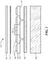
- the RFID tag 100may consist of a number of layers, including a device layer that includes an RFID chip 130 and antenna 140 ( Fig. 2 ). Additionally, in order to facilitate the attachment of the RFID tag 100 to an object 200 ( Fig. 2 ), the RFID tag 100 may include a number of openings 110 extending through the RFID tag 100. The openings 110 may be used in conjunction with a number of protrusions (discussed in greater detail below) extending from the object 200 to secure the RFID tag 100 to the object 200. Once secured to the object 200, the RFID tag 100 may be used to track and monitor the object 200 to which it is secured.
- the RFID tag 100may consist of a number of layers.
- the RFID tag 100may include a main, device layer 120 having a substrate 125 upon which the RFID chip 130 and antenna 140 (e.g., a copper trace antenna) may be located.
- the substrate 125may be a polyethylene terephthalate (PETG) film.
- the RFID tag 100may also include a top layer 160 that is secured to the device layer 120 via a layer of adhesive 170.
- the top layer 160may be any number of polymers, for example, polypropylene (e.g., a polypropylene film), and, in some embodiments, may be opaque so that the RFID chip 130, and the antenna 140 are not visible through the top layer 160.
- the RFID tag 100can also include a second layer of adhesive 180 on the underside 127 of the substrate 125.
- This second layer of adhesive 180may be used to help secure the RFID tag 100 to the object 200 and may be used to hold the RFID tag 100 in place as the boss is created (discussed in greater detail below).
- the tag 100may include a release liner (not shown) that covers and protects the adhesive layer 180 prior to the tag 100 being secured to the object 200. In such embodiments, when the tag 100 is to be secured to the object 200, the user may simply remove the release line to expose the adhesive layer 180 and stick the RFID tag 100 to the object 200.
- the adhesive layers 170/180can be a layer of standard glue (e.g., Fasson® S333 adhesive by Avery-Dennison).
- the second adhesive layer 180may include a stronger adhesive than that of the first adhesive layer 170 used to secure the top layer 160 to the substrate 125.
- the second adhesive layer 180may be a layer of high bond adhesive, for example, Very High Bond Adhesive (VHBTM) from 3MTM. It should be noted that using the VHB adhesive for the second adhesive layer 180 makes it more difficult for someone to remove the RFID tag 100 from the object 200.
- VHBTMVery High Bond Adhesive
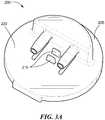
- the object 200may have protrusions 210 extending from a surface 220 of the object 200.
- the protrusions 210can extend from the cap (e.g., an inner cap 205) of the storage container.
- the protrusions 210can be injection molded and integral with the object 200 (e.g., integral with the inner cap 205).
- the protrusions 210can be the same material (or a different material) as the object (e.g., high-density polyethylene (HDPE)), and can be a solid structure extending from the object 200.
- HDPEhigh-density polyethylene
- the protrusions 210can be molded from the underside of the object (e.g., from the underside of the inner cap 205 during manufacturing of the object 200).
- the protrusions 210may have a hollow interior 212 ( Fig. 3B ) and/or the object 200 (e.g., the inner cap 205) may have an opening 207 (e.g., if the object 200 has an open inner volume) or hollow area (e.g., if the object 200 is solid) ( Fig. 3B ) at the base of the protrusions 210.
- the hollow area/opening 207will create hole(s) in/through the object 200.
- breaking the protrusions 210will create holes through the inner cap 205 and into the interior of the blood component storage container.
- the protrusions 210can pass through the openings 110 in the substrate 125 (and the top layer 160 if the RFID tag 100 includes the top layer 160) of the RFID tag 100. As mentioned above, the protrusions 210 can be melted to form a boss 230 ( Fig. 5 ) that, in turn, secures the RFID tag 100 to object 200. To that end, once the RFID tag 100 is in place on the object 200 and the protrusions 210 extend through the openings 110 ( Fig. 4 ), a heated die 300 may be used to melt the protrusions 210 and form the boss 230 shown in Figure 5 .
- the boss 230may cover and, in some embodiments, partially encapsulate a portion of the RFID tag 100. In this manner, the boss 230 can protect some of the various components of the RFID tag 100.
- the protrusions 210 and the openings 110can be located on either side of the RFID chip 130 such that, when the protrusions 210 are melted to form the boss 230, the boss 230 covers and protects the RFID chip 210 from damage.
- the boss 230may cover the RFID chip 130 on all sides (except for the bottom) and partially encapsulate the RFID chip 130, depending on the materials and process used, the boss 230 may or may not bond with the substrate 125. For example, in some embodiments, there may be a small space between the boss 230 and the substrate 125, and/or there may only be some mechanical gripping between the boss 230 and the substrate 125 (e.g., there may not be a chemical bond).
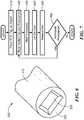
- Figure 6shows an exemplary die 300 that may be used to melt the protrusions 210 to form the boss 230.
- the die 300may include a main body 310 (e.g., a cylindrical shaft) and an indentation 320 formed in the bottom surface 330 of the body 310.
- a main body 310e.g., a cylindrical shaft
- an indentation 320formed in the bottom surface 330 of the body 310.
- the thermal mass of the die 300in order to allow the temperature of the die 300 to change quickly.
- the surface of the indentation 320may include a non-stick coating (e.g., a Teflon or similar coating) that helps prevent the melted protrusion material and the boss 230 from sticking to the die 300.
- the indentation 320 within the die 300may include a logo or similar mark that may be imprinted into the boss 230.
- the logo/markmay be the logo of the company that manufactures/produces the object 200 (or the contents thereof), branding promoting the security of the tag retention system, the date the RFID tag 100 was secured to the object 200, the initials (or other identification) of an inspector tasked with inspecting the object 200, and/or a mark indicating the type and/or contents of the object 200.
- the size of the indentation 320(and the protrusions 210) can vary depending on the object 200, RFID tag 100 and the application, to ensure that the boss(es) 230 are formed properly, the sizes of the indentation 320 and the protrusions should be such that the melted protrusion material is sufficient to completely fill the indentation 320. Furthermore, it is important to note that the size of the protrusions 210 and the volume of the indentation 320 determine, at least in part, the size of the boss(es) 230 created. Therefore, in applications in which more significant damage to the object 200 and RFID tag 100 is desired, larger protrusions 210 and a larger indentation 320 may be used to create larger boss(es) 230.
- some embodiments of the present inventionmay utilize an induction heater to heat the die 300 to the desired temperature (e.g., a temperature above the melting point of the protrusion material).
- the desired temperaturee.g., a temperature above the melting point of the protrusion material.
- the usermay shut off (or otherwise remove) the heat source and allow the die 300 to cool.
- the back of the die 300e.g., the area away from the indentation 320 will absorb the heat to cool the portion of the die 300 around/near the indentation.
- Figures 1 and 3-5show an RFID tag 100 with only a single pair of openings 110 and an object 200 with only a single pair of protrusions 210 (e.g., to create a single boss 230), it is important to note that other embodiments can have more than one pair of each.
- the RFID tag 100can have two or more pairs of openings 100 and the object 200 can have two or more pairs of protrusions 210. In this manner, some embodiments can have/create several bosses 230 located at various locations on the RFID tag 100.
- the RFID tag 100will not require the second adhesive layer 180 because the RFID tag 100 will be sufficiently pinned down/secured to the object via the bosses 230.
- the bosses 230may be the primary means to secure the RFID tag 100 to the object 200.
- the location of the protrusions 210 and openings 110 (and the bosses 230) relative to the antenna 140 and the RFID chip130can impact the performance of the RFID tag 100.
- the antenna 140, the top layer 160 and the substrate 125 of the RFID tag 100essentially form a capacitor.
- the capacitance of the RFID tag 100impacts the timing of the resistor-capacitor (RC) circuit that, in turn, is a characteristic of the UHF operation of the RFID tag 100 (e.g., the natural frequency of operation of the RFID tag 100).
- the boss 230is formed over a portion of the antenna 130, the capacitance value of the RFID tag 100 may shift and alter the performance of the RFID tag 100. Therefore, in some embodiments, it may be desirable to locate the protrusions 210 and openings 110 away from the antenna 130 to avoid any potential interference with the performance of the antenna 130 and/or RFID tag 100.
- some embodiments of the present inventionmay compensate for any shift in the capacitance value caused by the boss(es) 230.
- the RFID tag 100 and the antenna 130can be designed such that the RFID tag is inoperable until the bosses 230 are formed and the tag 100 is secured to the object.
- the RFID tag 100can be designed such that the capacitance shift created by securing the tag 100 to the object 200 and creating the bosses 230 (e.g., over a portion of the antenna 130) causes the RFID tag 100 to be operable.
- some embodiments of the present inventioncan ensure that an RFID tag 100 will be operable only when secured to the intended object 200 and prevent a different RFID tag 100 from be secured to the object 200.
- FIG. 7is a flowchart depicting a method for securing an RFID tag 100 to an object 200 in accordance with some embodiments of the present invention.
- the usermay place the RFID tag 100 onto the object 200 (Step 410) such that the openings 110 are placed over the protrusions 210 on the object 200.
- some embodiments of the RFID tag 100can have an adhesive layer (e.g., second adhesive layer 180) on the underside of the substrate 125 of the RFID tag 100. In such embodiments, the second adhesive layer 180 will hold the RFID tag 100 in place once on the object 200. If the RFID tag 100 does not have a second adhesive layer 180 (e.g., if there are multiple pairs of openings 110 and protrusions 210), the protrusions 210 may hold the RFID tag 100 in place.
- an adhesive layere.g., second adhesive layer 180
- the usermay then place the heated die 300 on the protrusions 210 (Step 420).
- the heated die 300or a room temperature die that is subsequently heated, for example, with the induction heater discussed above
- the protrusions 210will begin to melt at the point of contact with the die 300 (Step 430).
- the usermay then push down on the die 300 to further melt the protrusions 210 until the die 300 contacts the substrate 125.
- the protrusion materialfills the indentation 320 in the die 300.
- the temperature required to melt the protrusions 210should be below the temperature at which the RFID tag 100 may be damaged.
- the temperature required to melt the protrusions 210 and the temperature of the die 300should be below the melting point of the various layers of the RFID tag 100 (e.g., the substrate 125, top layer 160, etc.), and below the temperature at which the RFID chip 130 and antenna 140 may be damaged.
- the die 300may simply be a handheld die (e.g., a hand iron) that the user manually manipulates (e.g., manually puts into contact with the protrusions 210 and moves downward to melt the protrusions 210).
- the die 300may be located on a pneumatic or hydraulic press or similar device that allows the die 300 to travel up and down (e.g., towards and away from the RFID tag 100).
- the die 300may be located on an automated press so that the melting process can be automated.
- the usermay then remove the heat source, allow the die 300 to cool (Step 440), and remove the die 300 from the RFID tag 100 (Step 450).
- Step 440By allowing the die 300 to cool prior to removal, various embodiments of the present invention allow the melted material to begin to harden/set and the boss 230 to form. This, in turn, helps to prevent the melted material (and the newly formed boss 230) from sticking to the die 300.
- the surface of the indentation 320 within the die 300has a non-stick surface, the die 300 may be removed sooner as compared to embodiments without a non-stick coating.
- the non-stick coatingmay reduce the overall cycle time required to form the boss(es) 230.
- the methodmay then repeat steps 420-450 to melt the additional protrusions and form the additional bosses 230.
- boss(es) 230to help secure the RFID tag 100 to the object 200
- various embodiments of the present inventionexhibit tamper resistant and tamper-evident characteristics.
- an individualin order to remove the RFID tag 100 from the object 200, an individual must break off the boss(es) 230 that are securing the tag 100 to the object 200.
- the boss(es) 230(along with the material used to create them) must be broken off to remove the RFID tag 100, one cannot replace a removed RFID tag 100 with another tag 100 because there would be no material remaining to create a new boss 230.
- the lack of a boss 230 and/or a visibly broken-off boss 230would be easily evident to someone inspecting the object 200.
- the object 200e.g., the blood component storage container
- the object 200may also be destroyed by creating holes through a portion of the object 200 (e.g., the inner cap 205).
- some embodiments of the present inventioncan have one or more weakened areas 150 within the substrate 125 of the RFID tag 100.
- the weakened areas 150may act as tear initiation points during removal, and may be cuts, perforations, or similar structures within the substrate 125 that weaken the substrate 125 in the area of the cut/perforation. In this manner, when a tensile force is applied to the RFID tag 100 (e.g., during removal from the object), the tensile load will cause the substrate 125 to tear at the weakened area 150. As discussed in greater detail below, this tearing, in turn, may propagate across the antenna 140 and/or RFID chip 130, thereby destroying the RFID tag 100.
- the weakened areas 150may be located within/between the various sections of the antenna 140. It is also important to note that the weakened areas 150 can extend below the antenna (e.g., such that the portion of the substrate 125 directly below the antenna is weakened) or the weakened area 150 can stop just prior to the antenna 140 and continue on the other side of the antenna 140 (e.g., such that the portion of the substrate 125 directly below the antenna 140 is not weakened/cut but the portion of the substrate 125 on either side of the antenna 140 is weakened/cut).
- the weakened area(s) 150may be strategically placed relative to the boss(es) 230.
- the weakened area(s) 150may be placed such that, as an individual begins to pull the tag 100 and the RFID tag 100 begins to lift off the object 200, the boss(es) 230 keep the remainder of the tag 100 firmly secured to the object. As the individual continues to pull on the RFID tag 100, the tensile load on the tag 100 will be concentrated on the weakened area(s) 150.
- the weakened areas 150reduce the tensile load required to tear the substrate 125 and the load required to break the boss(es) 230 or otherwise pull the RFID tag 100 off of the object 200 is greater than the load that the weakened area 150 can support, the applied tensile load will tear the substrate 125 at the weakened area.
- the antenna 140cannot support the tensile load required to remove the tag 100 from the object 200. Therefore, the tear will propagate through the antenna 140 (and any similar conductive or semi-conductive material), the first adhesive layer 170 and the top layer 160. This, in turn, will sever the electrical connection and render the RFID tag 100 inoperable.
Landscapes
- Engineering & Computer Science (AREA)
- Physics & Mathematics (AREA)
- General Physics & Mathematics (AREA)
- Theoretical Computer Science (AREA)
- Computer Hardware Design (AREA)
- Microelectronics & Electronic Packaging (AREA)
- Mechanical Engineering (AREA)
- Computer Networks & Wireless Communication (AREA)
- Details Of Rigid Or Semi-Rigid Containers (AREA)
Description
- The present invention relates to a method and system for securing RFID tags to an object.
- Radio frequency identification (RFID) tags are commonly used to monitor and track a variety of goods. In particular, RFID tags may be secured to and/or formed directly within (e.g., molded within) an object or a storage container. These RFID tags are then programmed with information relating to the object and/or the substance contained within the storage container. The RFID tags may then be scanned during storage and/or transport to obtain the product details.
- For valuable products/objects, some individuals may have an incentive to tamper with and/or switch the RFID tag with an RFID tag from another object/container. For example, in the context of blood products, if one bottle of blood product is marked as HIV+ (and therefore is unusable), and another container of acceptable blood product breaks, an individual may be tempted to switch the RFID tag of the broken bottle of blood product with the RFID tag on the bottle marked as HIV+. As one would expect, this would create a significant health risk to a patient receiving the HIV+ blood product.Document
US 2010/0007501 A1 concerns a container having an RFID tag by means of a stud or RFID tag retainer. DocumentUS 2007/0139202 A1 concerns a method for manufacturing an object having an encapsulated RFID tag. - The invention is set out in claims 1 and 8. In a first embodiment of the invention there is provided a method for securing an RFID tag to an object. The RFID tag may include an RFID chip, an antenna electrically connected to the RFID chip, and a first and second opening extending through the RFID tag. The method may include placing the RFID tag on the object which, in turn, has a first and second protrusion (e.g., integral with the object) extending from the surface of the object. The first and second protrusions may extend through the first and second openings when the RFID tag is placed on the object. The method may then melt the first and second protrusions to create a single integral boss that covers at least a portion of the RFID tag and secures the RFID tag to the object. For example, melting the protrusions may include placing a heated die over the first and second protrusions.
- Prior to removing the die from the boss, the method may cool the die (or allow the die to cool) so the plastic is below it melting temperature before the die is removed from the part. In some embodiments the die may include a non-stick coating that helps prevent the boss from sticking to the die. The RFID tag may also include a substrate, an adhesive layer located above the substrate, and/or a top layer secured to the substrate via the adhesive layer. The RFID chip and antenna may be located on the substrate, and the first and second openings may pass through the substrate. The top layer may cover the antenna and RFID chip. To help adhere the RFID tag to the object, the RFID tag may further include a second adhesive layer located on an underside of the substrate.
- In some embodiments, the first opening may be located on a first side of the RFID chip and the second opening may be located on an opposing side of the RFID chip. In such embodiments, the boss may cover the RFID chip. Additionally or alternatively, the RFID tag may include a third and fourth opening, and the object may include a third and fourth protrusion. The third and fourth protrusions may extend through the third and fourth openings when the RFID tag is placed on the object. The method may include melting the third and fourth protrusions to create a second single integral boss that covers at least a portion of the RFID tag to secure the RFID tag to the object. For example, the second boss may cover a portion of the antenna. The RFID tag may be non-functional prior to melting the first and second protrusions (and/or the third and fourth protrusions) to create the boss(es), with the resultant electromagnetic properties of the construct enabling the tag's routine functionality.
- In accordance with further embodiments, a storage container may include a body defining the structure of the storage container, and first and second protrusions extending from the surface of a part of the storage container. An RFID tag may be secured to the surface of the storage container, and may include a substrate having a first and second opening extending through it. The RFID tag may also include an RFID chip located on the substrate, and an antenna located on the substrate and electrically connected to the RFID chip. The first and second openings may be configured to receive the first and second protrusions, and the first and second protrusions may be configured to be melted to create a single integral boss covering at least a portion of the RFID tag to secure the RFID tag to the object.
- In some embodiments, the first and second protrusions may be melted using a heated die that, in turn, may include a non-stick coating that helps prevent the boss from sticking to the die. The RFID tag may also include (1) an adhesive layer located on an underside of the substrate that adheres the RFID tag to the object, (2) a second adhesive layer located above the substrate, and (3) a top layer secured to the substrate via the second adhesive layer. The top layer may cover the antenna and RFID chip.
- The first and second openings may be located on opposite sides of the RFID chip so that the boss covers the RFID chip when formed. Additionally or alternatively, the RFID tag may include a third and fourth opening, and the storage container may include a third and fourth protrusion extending from the surface. The third and fourth protrusions may extend through the third and fourth openings when the RFID tag is placed on the object, and may be melted to create a second single integral boss. The second boss may cover at least a portion of the RFID tag (e.g., a portion of the antenna) to further secure the RFID tag to the object. The protrusions (first, second, third and fourth) may be integral with the object, and the RFID tag may be non-functional prior to melting one or more of the protrusions to create the boss.
- In accordance with further embodiments, an RFID tag may include a substrate with a pair of openings extending through it. The pair of openings may be configured to receive a pair of protrusions extending from a surface of an object to which the RFID tag is to be secured. The pair of protrusions may be configured to be melted (e.g., using a heated die) to create a single integral boss that covers at least a portion of the RFID tag and secures the RFID tag to the object. The RFID tag may also include an RFID chip and an antenna located on the substrate. The antenna may be electrically connected to the RFID chip. The die may include a non-stick coating that prevents the boss from sticking to the die.
- In some embodiments, the RFID tag may include an adhesive layer located on the underside of the substrate to adhere the RFID tag to the object. Additionally or alternatively, the RFID tag may include an adhesive layer located above the substrate, and a top layer secured to the substrate via the adhesive layer. The top layer may cover the antenna and RFID chip.
- The pair of openings may include a first opening and a second opening that are located on opposite sides of the RFID chip, such that the boss covers the RFID chip when formed. The RFID tag may also include a second pair of openings configured to receive a second pair of protrusions extending from the surface of the object. The second pair of protrusions may extend through the second pair of openings when the RFID tag is placed on the object, and may be melted to create a second single integral boss. The second boss may cover a portion of the RFID tag (e.g., a portion of the antenna) to further secure the RFID tag to the object. The RFID tag may be non-functional prior to melting the pair of protrusions to create the boss.
- In some embodiments, the substrate may contain diecuts or weakened portions so that the substrate and antenna tear or rip upon attempted removal of the tag. For example, during attempted removal, the boss may retain a portion of the tag, causing the tensile load to be concentrated on the weakened area. Furthermore, because the tensile load on the RFID tag is greater than what the weakened area can handle, the RFID tag will tear.
- The foregoing features of embodiments will be more readily understood by reference to the following detailed description, taken with reference to the accompanying drawings, in which:
Fig. 1 is a perspective view of an RFID tag in accordance with various embodiments of the present invention.Fig. 2 is a schematic cross-sectional side view of the RFID tag shown inFigure 1 in accordance with exemplary embodiments of the present invention.Fig. 3A is a perspective view of a portion of an object to which the RFID tag shown inFigure 1 may be secured, in accordance with some embodiments of the present invention.Fig. 3B is schematic cross-sectional view of an object having hollow protrusions, in accordance with some embodiments of the present invention.Fig. 3C is schematic cross-sectional view of an object having openings below the protrusions, in accordance with some embodiments of the present invention.Fig. 4 schematically shows the RFID tag shown inFigure 1 located on the object shown inFig. 3A , in accordance with various embodiments of the present invention.Fig. 5 schematically shows the RFID tag shown inFigure 1 secured to the object shown inFig. 3A , in accordance with various embodiments of the present invention.Fig. 6 is a perspective view of a die used to secure the RFID tag to the object, in accordance with various embodiments of the present invention.Fig. 7 is a flowchart showing a method of securing an RFID tag to an object, in accordance with illustrative embodiments of the present invention.- In illustrative embodiments, a radio-frequency identification (RFID) tag may have a substrate with a number of openings that receive protrusions extending from the object to which the RFID tag is to be secured. The protrusions may then be melted to create a "boss" that covers/encapsulates a portion of the RFID tag and secures the RFID tag to the object. To remove the RFID tag, the boss must be broken (or the substrate torn). In this manner, various embodiments of the present invention exhibit tamper-proof and/or tamper-evident characteristics upon attempted removal of the RFID tag from the object to which it is secured.
Figure 1 schematically shows anRFID tag 100 in accordance with some embodiments of the present invention. As discussed in greater detail below, theRFID tag 100 may consist of a number of layers, including a device layer that includes anRFID chip 130 and antenna 140 (Fig. 2 ). Additionally, in order to facilitate the attachment of theRFID tag 100 to an object 200 (Fig. 2 ), theRFID tag 100 may include a number ofopenings 110 extending through theRFID tag 100. Theopenings 110 may be used in conjunction with a number of protrusions (discussed in greater detail below) extending from theobject 200 to secure theRFID tag 100 to theobject 200. Once secured to theobject 200, theRFID tag 100 may be used to track and monitor theobject 200 to which it is secured.- As mentioned above and as shown in
Figure 2 , theRFID tag 100 may consist of a number of layers. For example, theRFID tag 100 may include a main,device layer 120 having asubstrate 125 upon which theRFID chip 130 and antenna 140 (e.g., a copper trace antenna) may be located. Although any number of materials may be used for thesubstrate 125, in some embodiments, thesubstrate 125 may be a polyethylene terephthalate (PETG) film. Additionally, in order to protect theRFID chip 130 andantenna 140 from dust, moisture, and other contamination that may negatively impact the performance of theRFID tag 100, theRFID tag 100 may also include atop layer 160 that is secured to thedevice layer 120 via a layer ofadhesive 170. Thetop layer 160 may be any number of polymers, for example, polypropylene (e.g., a polypropylene film), and, in some embodiments, may be opaque so that theRFID chip 130, and theantenna 140 are not visible through thetop layer 160. - In some embodiments, the
RFID tag 100 can also include a second layer of adhesive 180 on theunderside 127 of thesubstrate 125. This second layer of adhesive 180 may be used to help secure theRFID tag 100 to theobject 200 and may be used to hold theRFID tag 100 in place as the boss is created (discussed in greater detail below). To prevent theRFID tag 100 from accidentally sticking to the wrong surface, thetag 100 may include a release liner (not shown) that covers and protects theadhesive layer 180 prior to thetag 100 being secured to theobject 200. In such embodiments, when thetag 100 is to be secured to theobject 200, the user may simply remove the release line to expose theadhesive layer 180 and stick theRFID tag 100 to theobject 200. - The
adhesive layers 170/180 can be a layer of standard glue (e.g., Fasson® S333 adhesive by Avery-Dennison). Alternatively, the secondadhesive layer 180 may include a stronger adhesive than that of the firstadhesive layer 170 used to secure thetop layer 160 to thesubstrate 125. For example, the secondadhesive layer 180 may be a layer of high bond adhesive, for example, Very High Bond Adhesive (VHB™) from 3M™. It should be noted that using the VHB adhesive for the secondadhesive layer 180 makes it more difficult for someone to remove theRFID tag 100 from theobject 200. - As shown in
Figures 3A-C and4 , to facilitate the securement of theRFID tag 100 to theobject 200, theobject 200 may haveprotrusions 210 extending from asurface 220 of theobject 200. For example, if theobject 200 is a blood component storage container, theprotrusions 210 can extend from the cap (e.g., an inner cap 205) of the storage container. Theprotrusions 210 can be injection molded and integral with the object 200 (e.g., integral with the inner cap 205). Theprotrusions 210 can be the same material (or a different material) as the object (e.g., high-density polyethylene (HDPE)), and can be a solid structure extending from theobject 200. - Alternatively, in some embodiments, the
protrusions 210 can be molded from the underside of the object (e.g., from the underside of theinner cap 205 during manufacturing of the object 200). In such embodiments, theprotrusions 210 may have a hollow interior 212 (Fig. 3B ) and/or the object 200 (e.g., the inner cap 205) may have an opening 207 (e.g., if theobject 200 has an open inner volume) or hollow area (e.g., if theobject 200 is solid) (Fig. 3B ) at the base of theprotrusions 210. As discussed in greater detail below, in such embodiments, if someone attempts to remove theRFID tag 100 from the object by breaking the boss(es) 230, the hollow area/opening 207 will create hole(s) in/through theobject 200. For example, if theobject 200 is a blood component storage container, breaking theprotrusions 210 will create holes through theinner cap 205 and into the interior of the blood component storage container. - As best shown in
Figure 4 , when theRFID tag 100 is placed on the object 200 (e.g., as thetag 100 is placed on the inner cap 205), theprotrusions 210 can pass through theopenings 110 in the substrate 125 (and thetop layer 160 if theRFID tag 100 includes the top layer 160) of theRFID tag 100. As mentioned above, theprotrusions 210 can be melted to form a boss 230 (Fig. 5 ) that, in turn, secures theRFID tag 100 to object 200. To that end, once theRFID tag 100 is in place on theobject 200 and theprotrusions 210 extend through the openings 110 (Fig. 4 ), aheated die 300 may be used to melt theprotrusions 210 and form theboss 230 shown inFigure 5 . - In addition to securing the
RFID tag 100 to theobject 200, theboss 230 may cover and, in some embodiments, partially encapsulate a portion of theRFID tag 100. In this manner, theboss 230 can protect some of the various components of theRFID tag 100. For example, as shown inFigures 4 and5 , theprotrusions 210 and theopenings 110 can be located on either side of theRFID chip 130 such that, when theprotrusions 210 are melted to form theboss 230, theboss 230 covers and protects theRFID chip 210 from damage. Although theboss 230 may cover theRFID chip 130 on all sides (except for the bottom) and partially encapsulate theRFID chip 130, depending on the materials and process used, theboss 230 may or may not bond with thesubstrate 125. For example, in some embodiments, there may be a small space between theboss 230 and thesubstrate 125, and/or there may only be some mechanical gripping between theboss 230 and the substrate 125 (e.g., there may not be a chemical bond). Figure 6 shows anexemplary die 300 that may be used to melt theprotrusions 210 to form theboss 230. Thedie 300 may include a main body 310 (e.g., a cylindrical shaft) and anindentation 320 formed in thebottom surface 330 of thebody 310. To minimize the time it takes to create theboss 230, it is beneficial to minimize the thermal mass of the die 300 in order to allow the temperature of the die 300 to change quickly. To that end, it is important to minimize the physical size of thedie 300 and select materials that have high thermal conductivities (e.g., ferrous materials, silver-bearing alloys, or Titanium alloys). Additionally, the surface of theindentation 320 may include a non-stick coating (e.g., a Teflon or similar coating) that helps prevent the melted protrusion material and theboss 230 from sticking to thedie 300.- In some embodiments, the
indentation 320 within thedie 300 may include a logo or similar mark that may be imprinted into theboss 230. For example the logo/mark may be the logo of the company that manufactures/produces the object 200 (or the contents thereof), branding promoting the security of the tag retention system, the date theRFID tag 100 was secured to theobject 200, the initials (or other identification) of an inspector tasked with inspecting theobject 200, and/or a mark indicating the type and/or contents of theobject 200. - Although the size of the indentation 320 (and the protrusions 210) can vary depending on the
object 200,RFID tag 100 and the application, to ensure that the boss(es) 230 are formed properly, the sizes of theindentation 320 and the protrusions should be such that the melted protrusion material is sufficient to completely fill theindentation 320. Furthermore, it is important to note that the size of theprotrusions 210 and the volume of theindentation 320 determine, at least in part, the size of the boss(es) 230 created. Therefore, in applications in which more significant damage to theobject 200 andRFID tag 100 is desired,larger protrusions 210 and alarger indentation 320 may be used to create larger boss(es) 230. - As discussed in greater detail below, some embodiments of the present invention may utilize an induction heater to heat the
die 300 to the desired temperature (e.g., a temperature above the melting point of the protrusion material). When theprotrusions 210 are fully melted, the user may shut off (or otherwise remove) the heat source and allow thedie 300 to cool. During this time, the back of the die 300 (e.g., the area away from theindentation 320 will absorb the heat to cool the portion of thedie 300 around/near the indentation. - Although
Figures 1 and3-5 show anRFID tag 100 with only a single pair ofopenings 110 and anobject 200 with only a single pair of protrusions 210 (e.g., to create a single boss 230), it is important to note that other embodiments can have more than one pair of each. For example, in some embodiments, theRFID tag 100 can have two or more pairs ofopenings 100 and theobject 200 can have two or more pairs ofprotrusions 210. In this manner, some embodiments can have/createseveral bosses 230 located at various locations on theRFID tag 100. In such embodiments, if a sufficient number ofbosses 230 are created, theRFID tag 100 will not require the secondadhesive layer 180 because theRFID tag 100 will be sufficiently pinned down/secured to the object via thebosses 230. In other words, in some embodiments, thebosses 230 may be the primary means to secure theRFID tag 100 to theobject 200. - It is important to note that the location of the
protrusions 210 and openings 110 (and the bosses 230) relative to theantenna 140 and the RFID chip130 can impact the performance of theRFID tag 100. For example, theantenna 140, thetop layer 160 and thesubstrate 125 of theRFID tag 100 essentially form a capacitor. Furthermore, the capacitance of theRFID tag 100 impacts the timing of the resistor-capacitor (RC) circuit that, in turn, is a characteristic of the UHF operation of the RFID tag 100 (e.g., the natural frequency of operation of the RFID tag 100). Additionally, if theboss 230 is formed over a portion of theantenna 130, the capacitance value of theRFID tag 100 may shift and alter the performance of theRFID tag 100. Therefore, in some embodiments, it may be desirable to locate theprotrusions 210 andopenings 110 away from theantenna 130 to avoid any potential interference with the performance of theantenna 130 and/orRFID tag 100. - Additionally or alternatively, some embodiments of the present invention may compensate for any shift in the capacitance value caused by the boss(es) 230. In such embodiments, the
RFID tag 100 and theantenna 130 can be designed such that the RFID tag is inoperable until thebosses 230 are formed and thetag 100 is secured to the object. For example, theRFID tag 100 can be designed such that the capacitance shift created by securing thetag 100 to theobject 200 and creating the bosses 230 (e.g., over a portion of the antenna 130) causes theRFID tag 100 to be operable. In this manner, some embodiments of the present invention can ensure that anRFID tag 100 will be operable only when secured to the intendedobject 200 and prevent adifferent RFID tag 100 from be secured to theobject 200. Figure 7 is a flowchart depicting a method for securing anRFID tag 100 to anobject 200 in accordance with some embodiments of the present invention. First, the user may place theRFID tag 100 onto the object 200 (Step 410) such that theopenings 110 are placed over theprotrusions 210 on theobject 200. As mentioned above, some embodiments of theRFID tag 100 can have an adhesive layer (e.g., second adhesive layer 180) on the underside of thesubstrate 125 of theRFID tag 100. In such embodiments, the secondadhesive layer 180 will hold theRFID tag 100 in place once on theobject 200. If theRFID tag 100 does not have a second adhesive layer 180 (e.g., if there are multiple pairs ofopenings 110 and protrusions 210), theprotrusions 210 may hold theRFID tag 100 in place.- Once the
RFID tag 100 is placed on theobject 200 and theprotrusions 210 extend through theopenings 110, the user may then place theheated die 300 on the protrusions 210 (Step 420). As the heated die 300 (or a room temperature die that is subsequently heated, for example, with the induction heater discussed above) is applied to theprotrusions 210, theprotrusions 210 will begin to melt at the point of contact with the die 300 (Step 430). The user may then push down on thedie 300 to further melt theprotrusions 210 until the die 300 contacts thesubstrate 125. As theprotrusions 210 melt, the protrusion material fills theindentation 320 in thedie 300. - It is important to note that, to ensure that the
RFID tag 100 is not damaged, the temperature required to melt the protrusions 210 (and the temperature of the die 300) should be below the temperature at which theRFID tag 100 may be damaged. For example, the temperature required to melt theprotrusions 210 and the temperature of thedie 300 should be below the melting point of the various layers of the RFID tag 100 (e.g., thesubstrate 125,top layer 160, etc.), and below the temperature at which theRFID chip 130 andantenna 140 may be damaged. - Any number of processes and equipment may be used to move the
die 300 into place to melt theprotrusions 210. For example, thedie 300 may simply be a handheld die (e.g., a hand iron) that the user manually manipulates (e.g., manually puts into contact with theprotrusions 210 and moves downward to melt the protrusions 210). Alternatively, thedie 300 may be located on a pneumatic or hydraulic press or similar device that allows thedie 300 to travel up and down (e.g., towards and away from the RFID tag 100). Furthermore, in some embodiments, thedie 300 may be located on an automated press so that the melting process can be automated. It should be noted that, by melting theprotrusions 210 in this manner, various embodiments of the present invention require only minimal pressures (e.g., 5-10 PSI) to form thebosses 230. Therefore, theRFID chip 130 andantenna 140 are subjected to very low stresses which, in turn, reduces the risk of damaging theRFID tag 100. - Once the
protrusions 210 are fully melted and the protrusion material fills theindentation 320 within thedie 300, the user may then remove the heat source, allow thedie 300 to cool (Step 440), and remove the die 300 from the RFID tag 100 (Step 450). By allowing thedie 300 to cool prior to removal, various embodiments of the present invention allow the melted material to begin to harden/set and theboss 230 to form. This, in turn, helps to prevent the melted material (and the newly formed boss 230) from sticking to thedie 300. Additionally, it should be noted that, if the surface of theindentation 320 within thedie 300 has a non-stick surface, thedie 300 may be removed sooner as compared to embodiments without a non-stick coating. Therefore, the non-stick coating may reduce the overall cycle time required to form the boss(es) 230. Once thefirst boss 230 has been formed and thedie 300 has been removed, if there are additional protrusions 210 (Step 460) the method may then repeat steps 420-450 to melt the additional protrusions and form theadditional bosses 230. - It is important to note that, by utilizing boss(es) 230 to help secure the
RFID tag 100 to theobject 200, various embodiments of the present invention exhibit tamper resistant and tamper-evident characteristics. For example, in order to remove theRFID tag 100 from theobject 200, an individual must break off the boss(es) 230 that are securing thetag 100 to theobject 200. Additionally, because the boss(es) 230 (along with the material used to create them) must be broken off to remove theRFID tag 100, one cannot replace a removedRFID tag 100 with anothertag 100 because there would be no material remaining to create anew boss 230. The lack of aboss 230 and/or a visibly broken-offboss 230, would be easily evident to someone inspecting theobject 200. Moreover, in embodiments having hollow protrusions 210 (discussed above), the object 200 (e.g., the blood component storage container) may also be destroyed by creating holes through a portion of the object 200 (e.g., the inner cap 205). - Returning to
Figure 2 , in order to further improve the tamper-resistant characteristics of theRFID tag 100, some embodiments of the present invention can have one or moreweakened areas 150 within thesubstrate 125 of theRFID tag 100. The weakenedareas 150 may act as tear initiation points during removal, and may be cuts, perforations, or similar structures within thesubstrate 125 that weaken thesubstrate 125 in the area of the cut/perforation. In this manner, when a tensile force is applied to the RFID tag 100 (e.g., during removal from the object), the tensile load will cause thesubstrate 125 to tear at the weakenedarea 150. As discussed in greater detail below, this tearing, in turn, may propagate across theantenna 140 and/orRFID chip 130, thereby destroying theRFID tag 100. - In order to ensure destruction of the
RFID tag 100 during removal, it is preferable to locate the weakenedareas 150 in areas that will cause the tear to propagate across theantenna 140 and theRFID chip 130. For example, the weakenedareas 150 may be located within/between the various sections of theantenna 140. It is also important to note that the weakenedareas 150 can extend below the antenna (e.g., such that the portion of thesubstrate 125 directly below the antenna is weakened) or the weakenedarea 150 can stop just prior to theantenna 140 and continue on the other side of the antenna 140 (e.g., such that the portion of thesubstrate 125 directly below theantenna 140 is not weakened/cut but the portion of thesubstrate 125 on either side of theantenna 140 is weakened/cut). - The weakened area(s) 150 may be strategically placed relative to the boss(es) 230. For example, the weakened area(s) 150 may be placed such that, as an individual begins to pull the
tag 100 and theRFID tag 100 begins to lift off theobject 200, the boss(es) 230 keep the remainder of thetag 100 firmly secured to the object. As the individual continues to pull on theRFID tag 100, the tensile load on thetag 100 will be concentrated on the weakened area(s) 150. Furthermore, because the weakenedareas 150 reduce the tensile load required to tear thesubstrate 125 and the load required to break the boss(es) 230 or otherwise pull theRFID tag 100 off of theobject 200 is greater than the load that the weakenedarea 150 can support, the applied tensile load will tear thesubstrate 125 at the weakened area. - It is also important to note that, like the weakened
area 150 in thesubstrate 125, theantenna 140, theadhesive layers 170/180, and thetop layer 160 cannot support the tensile load required to remove thetag 100 from theobject 200. Therefore, the tear will propagate through the antenna 140 (and any similar conductive or semi-conductive material), the firstadhesive layer 170 and thetop layer 160. This, in turn, will sever the electrical connection and render theRFID tag 100 inoperable. - The embodiments of the invention described above are intended to be merely exemplary; numerous variations and modifications will be apparent to those skilled in the art. All such variations and modifications are intended to be within the scope of the present invention as defined in any appended claims.
Claims (14)
- A method for securing an RFID tag (100) to an object (200) comprising:providing an RFID tag (100) having an RFID chip (130) and an antenna (140) electrically connected to the RFID chip (140), the RFID tag (100) also having a first and second opening (110) extending therethrough;characterized by placing the RFID tag (100) on the object (200), the object (200) having a first and second protrusion (210) extending from a surface (220) of the object (200), the first and second protrusions (210) extending through the first and second openings (110) when the RFID tag (100) is placed on the object (200); andmelting the first and second protrusions (210) to create a single integral boss (230), the boss (230) covering at least a portion of the RFID tag (100), thereby securing the RFID tag (100) to the object (200).
- A method according to claim 1, wherein melting the first and second protrusions (210) includes placing a heated die (300) over the first and second protrusions (210).
- A method according to claim 2, further comprising:
cooling the die (300) and boss (230) prior to removing the die (300) from the boss (230). - A method according to claim 1, wherein the first opening (110) is located on a first side of the RFID chip (130) and the second opening (110) is located on an opposing side of the RFID chip (130), such that the boss (230) covers the RFID chip (130).
- A method according to claim 1, wherein the RFID tag (100) includes a third and fourth opening (110) and the object (200) includes a third and fourth protrusion (210), the third and fourth protrusions (210) extending through the third and fourth openings (110) when the RFID tag (100) is placed on the object (200), the method further comprising melting the third and fourth protrusions (210) to create a second single integral boss (230), the second boss (230) covering at least a portion of the RFID tag (100), thereby securing the RFID tag (100) to the object (200).
- A method according to claim 5, wherein the second boss (230) covers at least a portion of the antenna (140).
- A method according to claim 1, wherein RFID tag (100) is non-functional prior to melting the first and second protrusions (210) to create the boss (230) and/or the removal of the boss (230) during tampering damages the object (200).
- A system for securing an RFID tag (100) to an object (200) comprising:an RFID tag (100) having a substrate (125) with a first and second opening (110) extending therethrough,an RFID chip (130) located on the substrate (125), andan antenna (140) located on the substrate (125) and electrically connected to the RFID chip (130);characterized in thata first and second protrusion (210) extending from a surface (220) of the object (200), the first and second protrusion (210) configured to extend through the first and second openings (110) when the RFID tag (100) is placed on the object (200),wherein the first and second protrusions (210) are configured to be melted to create a single integral boss (230), the boss (230) covering at least a portion of the RFID tag (100), thereby securing the RFID tag (100) to the object (200).
- A system according to claim 8, wherein the first and second protrusions (210) are configured to be melted using a heated die (300).
- A system according to claim 8, further comprising:an adhesive layer (180) located on an underside of the substrate (125), the adhesive layer (180) adhering the RFID tag (100) to the object (200); or
an adhesive layer (170) located above the substrate (125); anda top layer (160) secured to the substrate (125) via the adhesive layer (170), the top layer (160) covering the antenna (140) and RFID chip (130). - A system according to claim 8, wherein the first and second openings (110) are located on opposite sides of the RFID chip (130), such that the boss (230) covers the RFID chip (130).
- A system according to claim 8, wherein the RFID tag (100) includes a third and fourth opening (110), and the object (200) includes third and fourth protrusions (210) extending from the surface (220), the third and fourth protrusions (210) extending through the third and fourth openings (110) when the RFID tag (100) is placed on the object (200), the third and fourth protrusions (210) configured to be melted to create a second single integral boss (230), the second boss (230) covering at least a portion of the RFID tag (100), thereby further securing the RFID tag (100) to the object (200).
- A system according to claim 12, wherein the second boss (230) covers at least a portion of the antenna (140).
- A system according to claim 8, wherein the RFID tag (100) is non-functional prior to melting the first and second protrusions (210) to create the boss (230) and/or removal of the boss (230) during tampering damages the object (200).
Priority Applications (1)
| Application Number | Priority Date | Filing Date | Title |
|---|---|---|---|
| EP19167610.5AEP3572346B1 (en) | 2013-06-18 | 2014-06-16 | Rfid tag and method of securing same to object |
Applications Claiming Priority (2)
| Application Number | Priority Date | Filing Date | Title |
|---|---|---|---|
| US201361836340P | 2013-06-18 | 2013-06-18 | |
| PCT/US2014/042508WO2014204844A1 (en) | 2013-06-18 | 2014-06-16 | Rfid tag and method of securing same to object |
Related Child Applications (1)
| Application Number | Title | Priority Date | Filing Date |
|---|---|---|---|
| EP19167610.5ADivisionEP3572346B1 (en) | 2013-06-18 | 2014-06-16 | Rfid tag and method of securing same to object |
Publications (3)
| Publication Number | Publication Date |
|---|---|
| EP3010816A1 EP3010816A1 (en) | 2016-04-27 |
| EP3010816A4 EP3010816A4 (en) | 2017-02-22 |
| EP3010816B1true EP3010816B1 (en) | 2019-05-08 |
Family
ID=52105155
Family Applications (2)
| Application Number | Title | Priority Date | Filing Date |
|---|---|---|---|
| EP14813178.2AActiveEP3010816B1 (en) | 2013-06-18 | 2014-06-16 | Rfid tag and method of securing same to object |
| EP19167610.5AActiveEP3572346B1 (en) | 2013-06-18 | 2014-06-16 | Rfid tag and method of securing same to object |
Family Applications After (1)
| Application Number | Title | Priority Date | Filing Date |
|---|---|---|---|
| EP19167610.5AActiveEP3572346B1 (en) | 2013-06-18 | 2014-06-16 | Rfid tag and method of securing same to object |
Country Status (4)
| Country | Link |
|---|---|
| US (1) | US9928457B2 (en) |
| EP (2) | EP3010816B1 (en) |
| HU (1) | HUE045283T2 (en) |
| WO (1) | WO2014204844A1 (en) |
Families Citing this family (18)
| Publication number | Priority date | Publication date | Assignee | Title |
|---|---|---|---|---|
| US9691014B2 (en)* | 2015-04-07 | 2017-06-27 | Neology, Inc. | Radio frequency identification tag in a license plate |
| US10099228B2 (en) | 2015-10-09 | 2018-10-16 | Invetech, Inc. | Apparatus for performing counter flow centrifugation and method of using same |
| EP3217326B1 (en)* | 2016-03-10 | 2019-10-23 | Assa Abloy AB | Tamper resistant tag |
| ES2584656B1 (en)* | 2016-05-13 | 2017-02-17 | Grifols, S.A. | RFID LABEL FOR DISPOSITION IN A BOTTLE FOR PRODUCTS DERIVED FROM BLOOD AND USE OF THE SAME |
| WO2020072945A1 (en) | 2018-10-05 | 2020-04-09 | TMRW Life Sciences, Inc. | Apparatus to preserve and identify biological samples at cryogenic conditions |
| US11281952B2 (en)* | 2019-06-04 | 2022-03-22 | Trovan, Ltd. | Systems and methods to secure transponders within RFID tags without potting elements |
| CN211033618U (en)* | 2019-07-19 | 2020-07-17 | 鼎贞(厦门)实业有限公司 | Radio frequency identification gasket for sealing bottle opening |
| MX2022005127A (en) | 2019-10-29 | 2022-08-04 | Tmrw Life Sciences Inc | Apparatus to facilitate transfer of biological specimens stored at cryogenic conditions. |
| WO2021178273A1 (en)* | 2020-03-02 | 2021-09-10 | Pamplona Communications | Apparatus and methods for coupling electronic tag to fluid container |
| AU2021276247A1 (en) | 2020-05-18 | 2022-11-17 | TMRW Life Sciences, Inc. | Handling and tracking of biological specimens for cryogenic storage |
| USD951481S1 (en) | 2020-09-01 | 2022-05-10 | TMRW Life Sciences, Inc. | Cryogenic vial |
| WO2022066943A1 (en) | 2020-09-24 | 2022-03-31 | TMRW Life Sciences, Inc. | Workstation and apparatus to facilitate transfer of biological specimens stored at cryogenic conditions |
| AU2021351505B2 (en) | 2020-10-02 | 2024-11-21 | TMRW Life Sciences, Inc. | Interrogation device and/or system having alignment feature(s) for wireless transponder tagged specimen containers and/or carriers |
| USD963194S1 (en) | 2020-12-09 | 2022-09-06 | TMRW Life Sciences, Inc. | Cryogenic vial carrier |
| EP4259333A4 (en) | 2020-12-10 | 2024-11-06 | TMRW Life Sciences, Inc. | SAMPLE HOLDER WITH WIRELESS TRANSPONDER FOR ATTACHMENT TO A COLLECTION BODY FOR CHILDREN |
| CA3202347A1 (en) | 2021-01-13 | 2022-07-21 | James Norman Craven | Systems, apparatus and methods to pick and/or place specimen containers |
| EP4085975A1 (en)* | 2021-05-07 | 2022-11-09 | Marioff Corporation OY | Bulb device |
| DE102023136607A1 (en)* | 2023-12-22 | 2025-06-26 | PMG Besitz GmbH & Co. KG | Fixable marking medium, method for producing the fixable marking medium, use of the fixable marking medium and system comprising a casting device/patch device and the fixable marking medium |
Family Cites Families (114)
| Publication number | Priority date | Publication date | Assignee | Title |
|---|---|---|---|---|
| US6045652A (en) | 1992-06-17 | 2000-04-04 | Micron Communications, Inc. | Method of manufacturing an enclosed transceiver |
| US7158031B2 (en) | 1992-08-12 | 2007-01-02 | Micron Technology, Inc. | Thin, flexible, RFID label and system for use |
| US5444223A (en) | 1994-01-11 | 1995-08-22 | Blama; Michael J. | Radio frequency identification tag and method |
| US5874214A (en) | 1995-04-25 | 1999-02-23 | Irori | Remotely programmable matrices with memories |
| US5777561A (en) | 1996-09-30 | 1998-07-07 | International Business Machines Corporation | Method of grouping RF transponders |
| US5883582A (en) | 1997-02-07 | 1999-03-16 | Checkpoint Systems, Inc. | Anticollision protocol for reading multiple RFID tags |
| US7061831B2 (en) | 1997-03-28 | 2006-06-13 | Carlos De La Huerga | Product labeling method and apparatus |
| US6147604A (en) | 1998-10-15 | 2000-11-14 | Intermec Ip Corporation | Wireless memory device |
| US6441741B1 (en) | 1999-05-17 | 2002-08-27 | Avid Identification Systems, Inc. | Overmolded transponder |
| DE19950532A1 (en) | 1999-10-20 | 2001-07-12 | Schoeller Plast Ag | Reusable transportation apparatus with tracking systems has transponder storing information on readiness condition of merchandise and usability profile |
| US6520544B1 (en) | 2000-01-10 | 2003-02-18 | Moore North America, Inc. | Radio frequency labels on reusable containers |
| US6943678B2 (en) | 2000-01-24 | 2005-09-13 | Nextreme, L.L.C. | Thermoformed apparatus having a communications device |
| US6281795B1 (en) | 2000-02-08 | 2001-08-28 | Moore North America, Inc. | RFID or EAS label mount with double sided tape |
| US6478229B1 (en) | 2000-03-14 | 2002-11-12 | Harvey Epstein | Packaging tape with radio frequency identification technology |
| GB0013619D0 (en) | 2000-06-06 | 2000-07-26 | Glaxo Group Ltd | Sample container |
| US6592043B1 (en) | 2000-08-17 | 2003-07-15 | Rick A. Britton | Fixture to mount a miniature proximity transponder to another article |
| US7070053B1 (en) | 2000-09-05 | 2006-07-04 | Cv Holdings Llc | System, method, and apparatuses for maintaining, tracking, transporting and identifying the integrity of a disposable specimen container with a re-usable transponder |
| US6951596B2 (en) | 2002-01-18 | 2005-10-04 | Avery Dennison Corporation | RFID label technique |
| US7102522B2 (en) | 2002-12-24 | 2006-09-05 | 3M Innovative Properties Company | Tamper-indicating radio frequency identification antenna and sticker, a radio frequency identification antenna, and methods of using the same |
| US7224280B2 (en) | 2002-12-31 | 2007-05-29 | Avery Dennison Corporation | RFID device and method of forming |
| US6940408B2 (en) | 2002-12-31 | 2005-09-06 | Avery Dennison Corporation | RFID device and method of forming |
| US20050019943A1 (en) | 2003-07-09 | 2005-01-27 | Chaoui Sam M. | Automatic blood analysis and identification system |
| US7061382B2 (en)* | 2003-12-12 | 2006-06-13 | Francis M. Claessens | Apparatus for electronically verifying the authenticity of contents within a container |
| US20050068182A1 (en) | 2003-09-30 | 2005-03-31 | Dunlap Richard L. | Application of radio frequency identification |
| US7271726B2 (en) | 2003-11-04 | 2007-09-18 | Chep Technology Pty Limited | RFID tag-pallet |
| CN1910600B (en) | 2004-01-23 | 2011-12-14 | 株式会社半导体能源研究所 | ID label, ID card, and ID tag |
| US7755484B2 (en) | 2004-02-12 | 2010-07-13 | Avery Dennison Corporation | RFID tag and method of manufacturing the same |
| US6983884B2 (en) | 2004-02-19 | 2006-01-10 | Neoteric Technology, Limited | Method and apparatus for monitoring transfusion of blood |
| US7215251B2 (en) | 2004-04-13 | 2007-05-08 | Impinj, Inc. | Method and apparatus for controlled persistent ID flag for RFID applications |
| US7350703B2 (en) | 2004-04-23 | 2008-04-01 | Ambartsoumian Gourgen | Low temperature radio frequency identification tracking system |
| US7626548B2 (en) | 2004-07-01 | 2009-12-01 | Lintec Corporation | Antenna circuit, IC inlet and IC tag |
| US7210635B2 (en) | 2004-07-02 | 2007-05-01 | Caterpillar Inc | System and method for encapsulation and protection of components |
| US8183052B2 (en) | 2004-08-19 | 2012-05-22 | Blood Cell Storage, Inc. | Methods and apparatus for sterility testing |
| PL1806967T3 (en) | 2004-09-29 | 2008-09-30 | Angelantoni Life Science S R L | Device and method for collecting, storing and dispensing blood bags |
| US7394383B2 (en) | 2004-10-07 | 2008-07-01 | West Pharmaceutical Services, Inc. | Closure for a container |
| WO2006049107A1 (en) | 2004-11-05 | 2006-05-11 | Brother Kogyo Kabushiki Kaisha | Tag tape roll, tag tape, and wireless tag circuit element cartridge |
| EP1813596A4 (en) | 2004-11-05 | 2010-03-31 | Univ Hokkaido Nat Univ Corp | PROCESS FOR THE SYNTHESIS OF ALPHA, ALPHA-DIFLUOROAMINE |
| US7637733B2 (en) | 2004-12-02 | 2009-12-29 | Graham Packaging Company, L.P. | Method and apparatus for reforming a portion of a plastic container to include a three-dimensional feature or transferable element |
| CA2589412C (en) | 2004-12-07 | 2011-02-01 | Sensormatic Electronics Corporation | Security device having a cable |
| US7212127B2 (en) | 2004-12-20 | 2007-05-01 | Avery Dennison Corp. | RFID tag and label |
| US7608457B2 (en) | 2005-03-10 | 2009-10-27 | Streck, Inc. | Blood collection and testing improvements |
| US7275682B2 (en) | 2005-03-24 | 2007-10-02 | Varian, Inc. | Sample identification utilizing RFID tags |
| EP1912135B1 (en) | 2005-04-06 | 2010-09-15 | Mallinckrodt, Inc. | System and methods for managing information relating to medical fluids and containers therefor |
| US7477150B2 (en) | 2005-05-04 | 2009-01-13 | Adalis Corporation | Radio frequency identification tag reinforcing tape and methods |
| US7501947B2 (en) | 2005-05-04 | 2009-03-10 | Tc License, Ltd. | RFID tag with small aperture antenna |
| US7528727B2 (en) | 2005-08-04 | 2009-05-05 | Sonoco Development, Inc. | Tracking device for polymeric packaging |
| US7804405B2 (en) | 2005-09-09 | 2010-09-28 | B&G International, Inc. | Tamper-evident bottle overcap for supporting an electronic tag |
| GB0521702D0 (en) | 2005-10-25 | 2005-11-30 | Bryant Keith C | Rfid enabled plastic container |
| US7713232B2 (en) | 2005-11-04 | 2010-05-11 | Medrad, Inc. | System for washing and processing of cells for delivery thereof to tissue |
| US7541931B1 (en) | 2005-11-17 | 2009-06-02 | California Polytechnic Corporation | Procedure for RFID tagging of reusable plastic containers (RPCs) |
| KR100653180B1 (en) | 2005-12-09 | 2006-12-05 | 한국전자통신연구원 | Built-in sensor RDF tag data storage device |
| US8279065B2 (en) | 2005-12-09 | 2012-10-02 | Tego Inc. | Methods and systems of a multiple radio frequency network node RFID tag |
| EP1958172B1 (en) | 2005-12-09 | 2014-11-12 | Tego Inc. | Multiple radio frequency network node rfid tag |
| US8242911B2 (en) | 2006-12-11 | 2012-08-14 | Tego Inc. | Composite multiple RFID tag facility |
| US8242908B2 (en) | 2005-12-09 | 2012-08-14 | Tego Inc. | Methods and systems of a multiple radio frequency network node RFID tag |
| US8269630B2 (en) | 2005-12-09 | 2012-09-18 | Tego Inc. | Methods and systems of a multiple radio frequency network node RFID tag |
| US20070139202A1 (en) | 2005-12-21 | 2007-06-21 | Symbol Technologies, Inc. | Radio frequency identification (RFID) solution to lost time spent on instrument inventory |
| US7388506B2 (en) | 2006-02-07 | 2008-06-17 | Rexam Healthcare Packaging Inc. | Closure and package with induction seal and RFID tag |
| US8097199B2 (en) | 2006-02-07 | 2012-01-17 | Rexam Healthcare Packaging Inc. | Molded plastic container and preform having insert-molded insert |
| US7794141B2 (en) | 2006-04-14 | 2010-09-14 | Deka Products Limited Partnership | Thermal and coductivity sensing systems, devices and methods |
| US7772981B1 (en) | 2006-05-08 | 2010-08-10 | Rexam Closures And Containers Inc. | Non-removable closure with integral RFID |
| JP4910690B2 (en) | 2006-06-12 | 2012-04-04 | ブラザー工業株式会社 | Tag tape roll |
| US7973664B1 (en) | 2006-08-04 | 2011-07-05 | Rexam Healthcare Packaging Inc. | Closure having RFID and foil |
| US8035518B2 (en) | 2006-09-07 | 2011-10-11 | B&G Plastics, Inc. | Set screw tag housing |
| US7479887B2 (en) | 2006-09-07 | 2009-01-20 | Rexam Healthcare Packaging Inc. | Closure and container package with RFID circuit |
| US7586417B2 (en) | 2006-11-10 | 2009-09-08 | Rexam Healthcare Packaging Inc. | RFID insert with disable feature and container that includes such an insert |
| US7922961B2 (en) | 2006-11-10 | 2011-04-12 | Rexam Healthcare Packaging Inc. | Molded plastic container having insert-molded insert and method of manufacture |
| US20080117058A1 (en) | 2006-11-21 | 2008-05-22 | Rcd Technology Inc. | Container security seal with destructible rfid tag |
| US20080122631A1 (en)* | 2006-11-29 | 2008-05-29 | Intermec Ip Corp. | Multiple band / wide band radio frequency identification (rfid) tag, such as for use as a metal mount tag |
| US7875227B2 (en) | 2006-12-01 | 2011-01-25 | Rexam Healthcare Packaging Inc. | Molded plastic container and preform having insert-molded RFID tag |
| US7850893B2 (en) | 2006-12-01 | 2010-12-14 | Rexam Healthcare Packaging Inc. | Molded plastic container and preform having insert-molded RFID tag |
| US7892471B2 (en) | 2006-12-08 | 2011-02-22 | Millipore Corporation | Wireless enabled device |
| US7705734B2 (en) | 2006-12-21 | 2010-04-27 | Martinelli Lawrence G | Secure product packaging |
| US7609166B2 (en) | 2007-01-04 | 2009-10-27 | Avery Dennison Corporation | RFID tag housing |
| JP4411555B2 (en) | 2007-03-26 | 2010-02-10 | ブラザー工業株式会社 | Tag label making device |
| FR2915105A1 (en) | 2007-04-19 | 2008-10-24 | Gambro Lundia Ab | MEDICAL FLUID TREATMENT APPARATUS AND METHOD FOR PREPARING MEDICAL FLUID TREATMENT APPARATUS. |
| US8120484B2 (en) | 2007-06-14 | 2012-02-21 | Rexam Healthcare Packaging Inc. | Closure and package with RFID kernel tag and boost antenna |
| US7859416B2 (en) | 2007-06-21 | 2010-12-28 | Round Rock Research, Llc | Method and system of attaching a RFID tag to an object |
| TW200905574A (en)* | 2007-07-03 | 2009-02-01 | Textilma Ag | Rfid transponder chip module with connecting means for an antenna, textile tag with an rfid transponder chip module, and use of an rfid transponder chip module |
| US8231024B2 (en) | 2007-08-08 | 2012-07-31 | Clear Lam Packaging, Inc. | Flexible, stackable container and method and system for manufacturing same |
| US8105487B2 (en) | 2007-09-25 | 2012-01-31 | Fresenius Medical Care Holdings, Inc. | Manifolds for use in conducting dialysis |
| US7777628B2 (en) | 2007-09-14 | 2010-08-17 | Tilson Jr Thomas M | Radio frequency identification system and method for use in cast concrete components |
| US7755488B2 (en) | 2007-09-21 | 2010-07-13 | Baxter International Inc. | Access disconnection detection system |
| JP2009093507A (en) | 2007-10-11 | 2009-04-30 | Hitachi Ltd | RFID tag |
| US7978079B2 (en) | 2007-10-12 | 2011-07-12 | Destron Fearing Corporation | Electronic tag |
| US8269670B2 (en) | 2007-10-12 | 2012-09-18 | Solstice Medical, Llc | Reusable, hermetic, medical grade RFID tag |
| WO2009049312A1 (en)* | 2007-10-12 | 2009-04-16 | Solstice Medical, Llc. | Small gamma shielded shorted patch rfid tag |
| DE102007050495A1 (en) | 2007-10-19 | 2009-04-23 | Pav Card Gmbh | ID card |
| US8215835B2 (en) | 2007-12-11 | 2012-07-10 | Tokitae Llc | Temperature-stabilized medicinal storage systems |
| US8215518B2 (en) | 2007-12-11 | 2012-07-10 | Tokitae Llc | Temperature-stabilized storage containers with directed access |
| US8094027B2 (en) | 2007-12-19 | 2012-01-10 | Abbott Laboratories | Method for molding an object containing a radio frequency identification tag |
| US8120485B2 (en) | 2007-12-19 | 2012-02-21 | Abbott Laboratories | Articles containing chipless radio frequency identification elements |
| US8115636B2 (en) | 2008-01-22 | 2012-02-14 | Avery Dennison Corporation | RFID tag with a reduced read range |
| US8212226B2 (en) | 2008-03-13 | 2012-07-03 | Rexam Healthcare Packaging Inc. | Plastic container and method of manufacture having molded-in-security features |
| US8427316B2 (en) | 2008-03-20 | 2013-04-23 | 3M Innovative Properties Company | Detecting tampered with radio frequency identification tags |
| US8098162B2 (en) | 2008-03-27 | 2012-01-17 | Rexam Healthcare Packaging Inc. | Attachment of an RFID tag to a container |
| US8161910B2 (en) | 2008-05-29 | 2012-04-24 | Allentown Caging & Equipment Co., Inc. | Integrated RFID tag in a card holder, cage, lid, and rack for use with inventorying and tracking of cage occupants and equipment |
| US8710958B2 (en)* | 2008-07-10 | 2014-04-29 | Abbott Laboratories | Containers having radio frequency identification tags and method of applying radio frequency identification tags to containers |
| US8049627B1 (en) | 2008-09-05 | 2011-11-01 | Walgreen Co. | Container with removable data storage mechanism |
| US8068028B2 (en) | 2008-09-26 | 2011-11-29 | Avery Dennison Corporation | Encapsulated RFID device for flexible, non-planar or curvilinear surfaces |
| US8466793B2 (en) | 2008-10-03 | 2013-06-18 | B&G Plastics, Inc. | Electronic tag holder for bottle neck |
| KR100899901B1 (en) | 2008-10-27 | 2009-05-29 | 대한민국 | Container lid with wireless tag |
| US8432286B2 (en) | 2008-12-03 | 2013-04-30 | B&G International, Inc. | Electronic tag holder for capped bottle neck |
| JP2010237877A (en)* | 2009-03-30 | 2010-10-21 | Fujitsu Ltd | RFID tag and method of manufacturing RFID tag |
| WO2010111743A1 (en) | 2009-04-03 | 2010-10-07 | Tagsys Sas | Rfid tag assembly and method |
| US8325047B2 (en) | 2009-04-08 | 2012-12-04 | Sabic Innovative Plastics Ip B.V. | Encapsulated RFID tags and methods of making same |
| US8173057B2 (en) | 2009-05-01 | 2012-05-08 | Cascade Engineering, Inc. | Waste container and related method of manufacture |
| US8758321B2 (en) | 2009-05-13 | 2014-06-24 | Haemonetics Corporation | System and method for active cooling of stored blood products |
| US8318499B2 (en) | 2009-06-17 | 2012-11-27 | Abbott Laboratories | System for managing inventories of reagents |
| US8267325B2 (en) | 2009-08-05 | 2012-09-18 | Avery Dennison Corporation | Wristband with elastic portion and inelastic portion containing a RFID inlay |
| US8292173B2 (en) | 2009-12-15 | 2012-10-23 | Carefusion 303, Inc. | Methods and systems for tracking inventory using an RFID tag tape |
| CA2789479C (en)* | 2010-02-09 | 2016-06-21 | Meps Real-Time, Inc. | Self-contained rfid-enabled drawer module |
| US9539374B2 (en) | 2010-05-12 | 2017-01-10 | Haemonetics Corporation | Donated blood collection kit |
| US8616459B2 (en)* | 2010-06-24 | 2013-12-31 | Smartrac Ip B.V. | Suspendable packages with radio frequency identification |
- 2014
- 2014-06-16EPEP14813178.2Apatent/EP3010816B1/enactiveActive
- 2014-06-16EPEP19167610.5Apatent/EP3572346B1/enactiveActive
- 2014-06-16HUHUE14813178Apatent/HUE045283T2/enunknown
- 2014-06-16USUS14/896,224patent/US9928457B2/enactiveActive
- 2014-06-16WOPCT/US2014/042508patent/WO2014204844A1/enactiveApplication Filing
Non-Patent Citations (1)
| Title |
|---|
| None* |
Also Published As
| Publication number | Publication date |
|---|---|
| US9928457B2 (en) | 2018-03-27 |
| EP3572346B1 (en) | 2022-08-03 |
| EP3010816A4 (en) | 2017-02-22 |
| EP3572346A1 (en) | 2019-11-27 |
| US20160117585A1 (en) | 2016-04-28 |
| EP3010816A1 (en) | 2016-04-27 |
| HUE045283T2 (en) | 2019-12-30 |
| WO2014204844A1 (en) | 2014-12-24 |
Similar Documents
| Publication | Publication Date | Title |
|---|---|---|
| EP3010816B1 (en) | Rfid tag and method of securing same to object | |
| US9626620B2 (en) | Frangible RFID tag and method of producing same | |
| JP5876018B2 (en) | Resin overcap with IC tag | |
| EP3022688B1 (en) | Monitoring product integrity of a pharmaceutical product in a vial using a miniaturized electronic sensor tag | |
| AU2017248444A1 (en) | A security cover and a container covered with such a cover | |
| JP6303261B2 (en) | Overcap and container with overcap | |
| US20250292055A1 (en) | Labelling assembly for a multi-part container, system and method for applying a labelling assembly to a multi-part container | |
| WO2020081900A1 (en) | Rfid foil tag | |
| CN114787046A (en) | Closure device for containers with pharmaceutical ingredients | |
| JP5139226B2 (en) | RFID chip label | |
| WO2012131144A1 (en) | Radio-frequency identification tag with securing portion | |
| JP6123264B2 (en) | Cap with IC tag | |
| JP2010091614A (en) | Label for rfid chip | |
| US20070164116A1 (en) | Flexible tube comprising an electronic component | |
| US11851254B2 (en) | System for closing packaging and system for authenticating packaging comprising a frangible radiofrequency identification tag | |
| JP6123263B2 (en) | Composite cap | |
| JP5035041B2 (en) | Vulnerable labels and how to use them | |
| AU2017101917A4 (en) | Smart capsules | |
| EP4155054B1 (en) | Preform layered body and layered container | |
| US20100288720A1 (en) | Security Device for Use with a Bottle | |
| JP2011164882A (en) | Ic tag label and ic tag label manufacturing method | |
| JP4281566B2 (en) | Thermoplastic molding | |
| CN117313774A (en) | Multifunctional tag, application, system and method for manufacturing multifunctional tag | |
| WO2024052270A1 (en) | Flexible electronic tag for application on a product and product comprising the flexible electronic tag | |
| HK1132721B (en) | Closure assembly |
Legal Events
| Date | Code | Title | Description |
|---|---|---|---|
| PUAI | Public reference made under article 153(3) epc to a published international application that has entered the european phase | Free format text:ORIGINAL CODE: 0009012 | |
| 17P | Request for examination filed | Effective date:20151209 | |
| AK | Designated contracting states | Kind code of ref document:A1 Designated state(s):AL AT BE BG CH CY CZ DE DK EE ES FI FR GB GR HR HU IE IS IT LI LT LU LV MC MK MT NL NO PL PT RO RS SE SI SK SM TR | |
| AX | Request for extension of the european patent | Extension state:BA ME | |
| DAX | Request for extension of the european patent (deleted) | ||
| A4 | Supplementary search report drawn up and despatched | Effective date:20170120 | |
| RIC1 | Information provided on ipc code assigned before grant | Ipc:B65D 23/14 20060101AFI20170116BHEP Ipc:G06K 19/04 20060101ALI20170116BHEP | |
| GRAP | Despatch of communication of intention to grant a patent | Free format text:ORIGINAL CODE: EPIDOSNIGR1 | |
| STAA | Information on the status of an ep patent application or granted ep patent | Free format text:STATUS: GRANT OF PATENT IS INTENDED | |
| RIC1 | Information provided on ipc code assigned before grant | Ipc:G06K 19/077 20060101ALI20181126BHEP Ipc:B65D 23/14 20060101AFI20181126BHEP Ipc:G06K 19/04 20060101ALI20181126BHEP | |
| INTG | Intention to grant announced | Effective date:20181217 | |
| GRAS | Grant fee paid | Free format text:ORIGINAL CODE: EPIDOSNIGR3 | |
| GRAA | (expected) grant | Free format text:ORIGINAL CODE: 0009210 | |
| STAA | Information on the status of an ep patent application or granted ep patent | Free format text:STATUS: THE PATENT HAS BEEN GRANTED | |
| AK | Designated contracting states | Kind code of ref document:B1 Designated state(s):AL AT BE BG CH CY CZ DE DK EE ES FI FR GB GR HR HU IE IS IT LI LT LU LV MC MK MT NL NO PL PT RO RS SE SI SK SM TR | |
| REG | Reference to a national code | Ref country code:GB Ref legal event code:FG4D | |
| REG | Reference to a national code | Ref country code:CH Ref legal event code:EP Ref country code:AT Ref legal event code:REF Ref document number:1129783 Country of ref document:AT Kind code of ref document:T Effective date:20190515 | |
| REG | Reference to a national code | Ref country code:DE Ref legal event code:R096 Ref document number:602014046494 Country of ref document:DE Ref country code:IE Ref legal event code:FG4D | |
| REG | Reference to a national code | Ref country code:RO Ref legal event code:EPE | |
| REG | Reference to a national code | Ref country code:NL Ref legal event code:FP | |
| REG | Reference to a national code | Ref country code:LT Ref legal event code:MG4D | |
| PG25 | Lapsed in a contracting state [announced via postgrant information from national office to epo] | Ref country code:FI Free format text:LAPSE BECAUSE OF FAILURE TO SUBMIT A TRANSLATION OF THE DESCRIPTION OR TO PAY THE FEE WITHIN THE PRESCRIBED TIME-LIMIT Effective date:20190508 Ref country code:NO Free format text:LAPSE BECAUSE OF FAILURE TO SUBMIT A TRANSLATION OF THE DESCRIPTION OR TO PAY THE FEE WITHIN THE PRESCRIBED TIME-LIMIT Effective date:20190808 Ref country code:PT Free format text:LAPSE BECAUSE OF FAILURE TO SUBMIT A TRANSLATION OF THE DESCRIPTION OR TO PAY THE FEE WITHIN THE PRESCRIBED TIME-LIMIT Effective date:20190908 Ref country code:SE Free format text:LAPSE BECAUSE OF FAILURE TO SUBMIT A TRANSLATION OF THE DESCRIPTION OR TO PAY THE FEE WITHIN THE PRESCRIBED TIME-LIMIT Effective date:20190508 Ref country code:AL Free format text:LAPSE BECAUSE OF FAILURE TO SUBMIT A TRANSLATION OF THE DESCRIPTION OR TO PAY THE FEE WITHIN THE PRESCRIBED TIME-LIMIT Effective date:20190508 Ref country code:LT Free format text:LAPSE BECAUSE OF FAILURE TO SUBMIT A TRANSLATION OF THE DESCRIPTION OR TO PAY THE FEE WITHIN THE PRESCRIBED TIME-LIMIT Effective date:20190508 Ref country code:HR Free format text:LAPSE BECAUSE OF FAILURE TO SUBMIT A TRANSLATION OF THE DESCRIPTION OR TO PAY THE FEE WITHIN THE PRESCRIBED TIME-LIMIT Effective date:20190508 Ref country code:ES Free format text:LAPSE BECAUSE OF FAILURE TO SUBMIT A TRANSLATION OF THE DESCRIPTION OR TO PAY THE FEE WITHIN THE PRESCRIBED TIME-LIMIT Effective date:20190508 | |
| PG25 | Lapsed in a contracting state [announced via postgrant information from national office to epo] | Ref country code:LV Free format text:LAPSE BECAUSE OF FAILURE TO SUBMIT A TRANSLATION OF THE DESCRIPTION OR TO PAY THE FEE WITHIN THE PRESCRIBED TIME-LIMIT Effective date:20190508 Ref country code:RS Free format text:LAPSE BECAUSE OF FAILURE TO SUBMIT A TRANSLATION OF THE DESCRIPTION OR TO PAY THE FEE WITHIN THE PRESCRIBED TIME-LIMIT Effective date:20190508 Ref country code:BG Free format text:LAPSE BECAUSE OF FAILURE TO SUBMIT A TRANSLATION OF THE DESCRIPTION OR TO PAY THE FEE WITHIN THE PRESCRIBED TIME-LIMIT Effective date:20190808 Ref country code:GR Free format text:LAPSE BECAUSE OF FAILURE TO SUBMIT A TRANSLATION OF THE DESCRIPTION OR TO PAY THE FEE WITHIN THE PRESCRIBED TIME-LIMIT Effective date:20190809 | |
| REG | Reference to a national code | Ref country code:HU Ref legal event code:AG4A Ref document number:E045283 Country of ref document:HU | |
| PG25 | Lapsed in a contracting state [announced via postgrant information from national office to epo] | Ref country code:DK Free format text:LAPSE BECAUSE OF FAILURE TO SUBMIT A TRANSLATION OF THE DESCRIPTION OR TO PAY THE FEE WITHIN THE PRESCRIBED TIME-LIMIT Effective date:20190508 Ref country code:EE Free format text:LAPSE BECAUSE OF FAILURE TO SUBMIT A TRANSLATION OF THE DESCRIPTION OR TO PAY THE FEE WITHIN THE PRESCRIBED TIME-LIMIT Effective date:20190508 Ref country code:SK Free format text:LAPSE BECAUSE OF FAILURE TO SUBMIT A TRANSLATION OF THE DESCRIPTION OR TO PAY THE FEE WITHIN THE PRESCRIBED TIME-LIMIT Effective date:20190508 | |
| REG | Reference to a national code | Ref country code:CH Ref legal event code:PL | |
| REG | Reference to a national code | Ref country code:DE Ref legal event code:R097 Ref document number:602014046494 Country of ref document:DE | |
| PG25 | Lapsed in a contracting state [announced via postgrant information from national office to epo] | Ref country code:MC Free format text:LAPSE BECAUSE OF FAILURE TO SUBMIT A TRANSLATION OF THE DESCRIPTION OR TO PAY THE FEE WITHIN THE PRESCRIBED TIME-LIMIT Effective date:20190508 Ref country code:SM Free format text:LAPSE BECAUSE OF FAILURE TO SUBMIT A TRANSLATION OF THE DESCRIPTION OR TO PAY THE FEE WITHIN THE PRESCRIBED TIME-LIMIT Effective date:20190508 | |
| PLBE | No opposition filed within time limit | Free format text:ORIGINAL CODE: 0009261 | |
| STAA | Information on the status of an ep patent application or granted ep patent | Free format text:STATUS: NO OPPOSITION FILED WITHIN TIME LIMIT | |
| REG | Reference to a national code | Ref country code:BE Ref legal event code:MM Effective date:20190630 | |
| PG25 | Lapsed in a contracting state [announced via postgrant information from national office to epo] | Ref country code:TR Free format text:LAPSE BECAUSE OF FAILURE TO SUBMIT A TRANSLATION OF THE DESCRIPTION OR TO PAY THE FEE WITHIN THE PRESCRIBED TIME-LIMIT Effective date:20190508 | |
| 26N | No opposition filed | Effective date:20200211 | |
| PG25 | Lapsed in a contracting state [announced via postgrant information from national office to epo] | Ref country code:IE Free format text:LAPSE BECAUSE OF NON-PAYMENT OF DUE FEES Effective date:20190616 Ref country code:PL Free format text:LAPSE BECAUSE OF FAILURE TO SUBMIT A TRANSLATION OF THE DESCRIPTION OR TO PAY THE FEE WITHIN THE PRESCRIBED TIME-LIMIT Effective date:20190508 | |
| PG25 | Lapsed in a contracting state [announced via postgrant information from national office to epo] | Ref country code:BE Free format text:LAPSE BECAUSE OF NON-PAYMENT OF DUE FEES Effective date:20190630 Ref country code:SI Free format text:LAPSE BECAUSE OF FAILURE TO SUBMIT A TRANSLATION OF THE DESCRIPTION OR TO PAY THE FEE WITHIN THE PRESCRIBED TIME-LIMIT Effective date:20190508 Ref country code:CH Free format text:LAPSE BECAUSE OF NON-PAYMENT OF DUE FEES Effective date:20190630 Ref country code:LU Free format text:LAPSE BECAUSE OF NON-PAYMENT OF DUE FEES Effective date:20190616 Ref country code:LI Free format text:LAPSE BECAUSE OF NON-PAYMENT OF DUE FEES Effective date:20190630 | |
| PG25 | Lapsed in a contracting state [announced via postgrant information from national office to epo] | Ref country code:CY Free format text:LAPSE BECAUSE OF FAILURE TO SUBMIT A TRANSLATION OF THE DESCRIPTION OR TO PAY THE FEE WITHIN THE PRESCRIBED TIME-LIMIT Effective date:20190508 | |
| PG25 | Lapsed in a contracting state [announced via postgrant information from national office to epo] | Ref country code:IS Free format text:LAPSE BECAUSE OF FAILURE TO SUBMIT A TRANSLATION OF THE DESCRIPTION OR TO PAY THE FEE WITHIN THE PRESCRIBED TIME-LIMIT Effective date:20190908 | |
| PG25 | Lapsed in a contracting state [announced via postgrant information from national office to epo] | Ref country code:MT Free format text:LAPSE BECAUSE OF FAILURE TO SUBMIT A TRANSLATION OF THE DESCRIPTION OR TO PAY THE FEE WITHIN THE PRESCRIBED TIME-LIMIT Effective date:20190508 | |
| PG25 | Lapsed in a contracting state [announced via postgrant information from national office to epo] | Ref country code:MK Free format text:LAPSE BECAUSE OF FAILURE TO SUBMIT A TRANSLATION OF THE DESCRIPTION OR TO PAY THE FEE WITHIN THE PRESCRIBED TIME-LIMIT Effective date:20190508 | |
| REG | Reference to a national code | Ref country code:AT Ref legal event code:UEP Ref document number:1129783 Country of ref document:AT Kind code of ref document:T Effective date:20190508 | |
| P01 | Opt-out of the competence of the unified patent court (upc) registered | Effective date:20230523 | |
| PGFP | Annual fee paid to national office [announced via postgrant information from national office to epo] | Ref country code:IT Payment date:20240619 Year of fee payment:11 | |
| PGFP | Annual fee paid to national office [announced via postgrant information from national office to epo] | Ref country code:DE Payment date:20250627 Year of fee payment:12 | |
| PGFP | Annual fee paid to national office [announced via postgrant information from national office to epo] | Ref country code:GB Payment date:20250627 Year of fee payment:12 | |
| PGFP | Annual fee paid to national office [announced via postgrant information from national office to epo] | Ref country code:NL Payment date:20250626 Year of fee payment:12 | |
| PGFP | Annual fee paid to national office [announced via postgrant information from national office to epo] | Ref country code:HU Payment date:20250612 Year of fee payment:12 Ref country code:FR Payment date:20250625 Year of fee payment:12 | |
| PGFP | Annual fee paid to national office [announced via postgrant information from national office to epo] | Ref country code:RO Payment date:20250605 Year of fee payment:12 Ref country code:AT Payment date:20250603 Year of fee payment:12 | |
| PGFP | Annual fee paid to national office [announced via postgrant information from national office to epo] | Ref country code:CZ Payment date:20250605 Year of fee payment:12 |