EP3009833B1 - In-process error checking by means of augmented reality - Google Patents
In-process error checking by means of augmented realityDownload PDFInfo
- Publication number
- EP3009833B1 EP3009833B1EP14003513.0AEP14003513AEP3009833B1EP 3009833 B1EP3009833 B1EP 3009833B1EP 14003513 AEP14003513 AEP 14003513AEP 3009833 B1EP3009833 B1EP 3009833B1
- Authority
- EP
- European Patent Office
- Prior art keywords
- component
- unit
- information
- error
- defect
- Prior art date
- Legal status (The legal status is an assumption and is not a legal conclusion. Google has not performed a legal analysis and makes no representation as to the accuracy of the status listed.)
- Active
Links
Images


Classifications
- G—PHYSICS
- G06—COMPUTING OR CALCULATING; COUNTING
- G06T—IMAGE DATA PROCESSING OR GENERATION, IN GENERAL
- G06T7/00—Image analysis
- G06T7/0002—Inspection of images, e.g. flaw detection
- G06T7/0004—Industrial image inspection
- G—PHYSICS
- G01—MEASURING; TESTING
- G01N—INVESTIGATING OR ANALYSING MATERIALS BY DETERMINING THEIR CHEMICAL OR PHYSICAL PROPERTIES
- G01N21/00—Investigating or analysing materials by the use of optical means, i.e. using sub-millimetre waves, infrared, visible or ultraviolet light
- G01N21/84—Systems specially adapted for particular applications
- G01N21/88—Investigating the presence of flaws or contamination
- G01N21/8851—Scan or image signal processing specially adapted therefor, e.g. for scan signal adjustment, for detecting different kinds of defects, for compensating for structures, markings, edges
- G—PHYSICS
- G01—MEASURING; TESTING
- G01N—INVESTIGATING OR ANALYSING MATERIALS BY DETERMINING THEIR CHEMICAL OR PHYSICAL PROPERTIES
- G01N21/00—Investigating or analysing materials by the use of optical means, i.e. using sub-millimetre waves, infrared, visible or ultraviolet light
- G01N21/84—Systems specially adapted for particular applications
- G01N21/88—Investigating the presence of flaws or contamination
- G01N21/95—Investigating the presence of flaws or contamination characterised by the material or shape of the object to be examined
- G01N21/9515—Objects of complex shape, e.g. examined with use of a surface follower device
- G—PHYSICS
- G06—COMPUTING OR CALCULATING; COUNTING
- G06T—IMAGE DATA PROCESSING OR GENERATION, IN GENERAL
- G06T19/00—Manipulating 3D models or images for computer graphics
- G06T19/006—Mixed reality
- G—PHYSICS
- G01—MEASURING; TESTING
- G01N—INVESTIGATING OR ANALYSING MATERIALS BY DETERMINING THEIR CHEMICAL OR PHYSICAL PROPERTIES
- G01N21/00—Investigating or analysing materials by the use of optical means, i.e. using sub-millimetre waves, infrared, visible or ultraviolet light
- G01N21/84—Systems specially adapted for particular applications
- G01N21/88—Investigating the presence of flaws or contamination
- G01N21/8851—Scan or image signal processing specially adapted therefor, e.g. for scan signal adjustment, for detecting different kinds of defects, for compensating for structures, markings, edges
- G01N2021/8887—Scan or image signal processing specially adapted therefor, e.g. for scan signal adjustment, for detecting different kinds of defects, for compensating for structures, markings, edges based on image processing techniques
- G01N2021/8893—Scan or image signal processing specially adapted therefor, e.g. for scan signal adjustment, for detecting different kinds of defects, for compensating for structures, markings, edges based on image processing techniques providing a video image and a processed signal for helping visual decision
- G—PHYSICS
- G06—COMPUTING OR CALCULATING; COUNTING
- G06T—IMAGE DATA PROCESSING OR GENERATION, IN GENERAL
- G06T2207/00—Indexing scheme for image analysis or image enhancement
- G06T2207/30—Subject of image; Context of image processing
- G06T2207/30108—Industrial image inspection
- G06T2207/30164—Workpiece; Machine component
Definitions
- the inventionrelates to an arrangement for the optical error checking of at least one component, in particular an aircraft, during the manufacturing process of the component.
- the inventionalso relates to a corresponding method for optical fault checking of the component.
- AFP technologyautomated fiber placement solves this problem through the use of a fully automated manufacturing process for composite components.
- robot-guided, fiber-reinforced plastic stripsare deposited along a predetermined path on a three-dimensional tool surface using pressure and temperature.
- the componentis made of carbon fiber ribbons, ribbon by ribbon, i.e. Layer by layer, built up.
- the usual procedure for checking the qualityis that after each shift, an employee examines the component for any quality deficits. Deviations in the position of the ribbons must be avoided at all costs, even if they are only a few millimeters, for example 2mm.
- various error patternscan occur when filing, e.g.
- the arrangement according to the inventionhas a fault recognition unit for recognizing a structural fault of the component and for determining at least one piece of fault information, and a means coupled to the fault recognition unit for the context-dependent display of the fault information on a component image in real time.
- the means for the context-dependent insertion of the error information on a component image in real timecorresponds to an extended reality system which supplements the visual inspection of the component.
- the user of the devicecan directly and easily recognize the structural defects and the failure information.
- One advantage of the solution according to the inventionis that the arrangement creates a clearer overview of the component, this component image being provided with additional information and enabling a faster and more precise inspection.
- the arrangement according to the inventionis suitable for optical fault checking of an aircraft component during the manufacturing process, the component to be examined advantageously being made of carbon fiber reinforced plastic (CFRP).
- the fault detection unithas at least one sensor module which, during the manufacturing process of the component, detects the presence of defects in adjacent ones Detect carbon fiber ribbons or determine the size of the defects or specify the number of carbon fiber ribbons.
- the error detection unitcan be part of a quality assurance system, for example.
- the structural defecthere corresponds to a gap or a gap arranged between the carbon fiber ribbons or a crack or the like.
- the means for context-dependent superimposition of the error information on a component image in real timehas, in particular, a position determination unit for determining exact information about the position of the component and the position of the user. Furthermore, the means has a processor unit coupled to the error detection unit and the position determination unit for processing the information determined by the error detection unit and position determination unit and for integrating the processed information in a component image and a visualization unit coupled to the processor unit for displaying the component image with the integrated information.
- the various units of the arrangement according to the inventioncan be coupled to one another by cables or (completely or partially) wirelessly.
- the data or informationcan thus be transmitted wirelessly. It is also conceivable to integrate some of these units in other units.
- the processor unitcan, for example, be integrated into the visualization unit and correspond to a portable optical aid.
- the position determining unit or the tracking systemis used here to record the exact location and position of the component.
- the determined error informationcan thus be overlapped on the component in real time and made recognizable to the user with the aid of the visualization unit.
- the position determination unitcan operate on an optical basis. In this case, optical cameras are used to record the surroundings, with the orientation taking place with the aid of landmarks.
- the landmarkscan have natural properties such as The tip of the nose or the corner of the eye or it can also be artificial. Artificial landmarks can have LEDs that flash at regular intervals or battery-operated markers that have no wiring.
- the systemcan locate itself on the component in which component features, which are recognized, for example, with a portable camera, are compared with the target data.
- Orientationcan also take place using electromagnetic or ultrasonic signals or mechanical elements.
- the visualization unithere corresponds to an optical aid for the user, which considerably accelerates component testing.
- the userno longer has to locate the fault or defect recognized by the fault detection unit on the component, since all the necessary fault information is available in real time in the component image displayed by the visualization unit.
- the information about the component positionis integrated with the component image, so that the user can very quickly find out the structural fault in the correct position on the component.
- the arrangement or the means for context-dependent superimposition of the fault information on a component image in real timehas a recording unit for recording the component image.
- Thiscan be a photo camera or a video camera that can be separated from the visualization unit or integrated with it.
- the arrangementcan pick up the real component via the pickup unit, process the image through the processor unit, for example to highlight the structural defects by changing the size or color, and using the visualization unit to show the user the changed, but photo-realistic image.
- the arrangementcan use a purely computer-generated virtual component image, the corresponding identifications of the faults being displayed at the correct position in the component image.
- the usercan run a virtual component (in its original size) in a free space, whereby the component may be purely virtual or covered with photos or optical scanned images of the original component.
- the usercan inspect the component without risk while the machine is still in operation. In this way, for example, an inspector can safely issue instructions for repairs and a second machine can be used to repair the damage to the component during the manufacturing process.
- the recording unitcan be an on-board camera, the image corresponding to a real-time image of the component.
- the visualization unithas a portable computer, such as a smartphone or a tablet, which can be accessed directly examining component can be directed.
- the visualization unithas a head-mounted display, such as, for example, wearable glasses or a helmet display. It is also conceivable to use contact lenses or bionic contact lenses or implants or targeted stimulation of parts of the brain or the optic nerve (to generate images in the head) that have a built-in display element with an integrated circuit, LEDs and an antenna for wireless communication exhibit.
- the visualization unithas an optical projector or a portable screen or a portable transparent display.
- a display with at least one camerato capture the real world and to represent an expanded view of this world through the display, an image with integrated expanded information being projected through the display or reflected on the display.
- the error informationhas the location or the coordinates of the structural error. In this way, the fault or the defect in the component can be located immediately or simply afterwards.
- the error informationcan show the severity of the structural error. It is thus possible for the user to mark an error as uncritical, as critical, as irreparable, etc. and, if necessary, to initiate appropriate measures through the arrangement.
- the visualization unitcan have a touchscreen display so that the user can activate certain functions when touching the screen. For example, it is conceivable to touch an error or icon shown on the display in order to assign a repair to be carried out to the appropriate technician or simply to enable a telephone conversation with the technician.
- the position determination unithas reference markers for calculating the component position.
- the arrangement with regard to the position in relation to the componentcan thus be found.
- the component positioncan also be controlled via an external signal, e.g. a GPS signal, or can be determined via a position measuring device.
- the Processor unitIn order to coordinate the movement of the visualization unit or the viewing direction of the visualization unit with the displayed component image, the Processor unit have a synchronization unit.
- the component imagemoves with it in accordance with the movement and the viewing direction of the visualization unit.
- the structural defects and the corresponding defect informationare shown in the component image. The user can thus approach the component and walk through it, with the previously measured or detected faults being displayed in the correct position every time he looks at the component. The search for the individual component defects is thus significantly accelerated.
- the visualization unithas a means for determining the location of the structural defects on the displayed component image.
- the arrangementcan thus lead the user to the corresponding fault locations by means of virtual arrows, as is the case with a navigation device.
- the method according to the invention for optical defect checking of a componentincludes the detection of a structural defect on the component and the determination of at least one piece of defect information by a defect detection unit and the context-dependent display of the defect information on a component image in real time.
- the methodcan be used here as an extension of a planned fault check of a component.
- the usergoes to the component without any indication of possible defects and, using the method according to the invention, receives information on the component image currently being viewed, such as e.g. the exact location of a gap or the size of that gap.
- the methodstep of the context-dependent insertion of the error information on a component image in real time, the determination of exact information about the position of the component and the position of the user by a position determination unit. Furthermore, the method has the processing of the error information and the information about the position of the component and the position of the user as well as the integration of the processed information in a component image by a processor unit and the display of the component image with the integrated information by a visualization unit.
- the imagecan be recorded by a recording unit and in particular in real time.
- the displayed component imagemoves with the movement of the visualization unit or the viewing direction of the visualization unit.
- the processing of the error informationincludes categorizing the structural error and, if necessary, initiating countermeasures. The user can thus evaluate the defect and, if necessary, take countermeasures directly at the location of the measurement. The fault position can also be saved.
- the usercan be guided directly and easily to the structural error or the defect, both in the case of nearby but very small and therefore invisible defects as well as in the case of a great distance to the component itself.
- the method according to the inventionalso enables additional information, such as About defects in underlying layers, about the size of the defect, as well as categorizing the defect and initiating countermeasures on site.
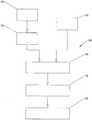
- the Figure 1describes an arrangement 1 for optical fault checking of a component 10, in particular an aircraft.
- the arrangement 1has a defect detection unit 20 which optically examines the surface of the component 10 in order to find structural defects.
- the component 10has carbon fiber ribbons, the defect detection unit 20 carrying out a defect check during the AFP production process of the component 10.
- the defect detection unit 20collects the defect information (position and size of the defect) and transmits this information to a means 30 for context-dependent insertion of the defect information on a component image B in real time.
- the means 30has a processor unit 31 and a position determination unit 32 which is coupled to the processor unit 31 and which determines the exact position of the component 10 and the user through the use of suitable reference markers 33.
- the processor unit 31processes the error information and the information ascertained by the position determination unit 32 and integrates this in a component image B.
- the imageis recorded by a recording unit 34 coupled to the processor unit 31.
- the processed component image Bis then transmitted from the processor unit 31 to a visualization unit 35 and thus displayed to the user.
- the processor unit 31also has a synchronization unit 36 in order to be able to coordinate the movement of the visualization unit 35 or the viewing direction of the visualization unit 35 with the displayed component image B.
- the Figure 2describes a visualization unit according to an embodiment of the invention.
- the visualization unitcorresponds to a transparent portable display 35 'with an integrated camera 34', which is equipped with a processor unit 31 (in FIG Figure 2 not shown) communicates wirelessly.
- the transparent display 35 'is directed towards the component 10 and shows a processed image B of the component 10 in real time, in which error information 41 about detected and displayed errors F 1 , F 2 is shown.
- the error information 41is generated by an error detection unit 20 (in the Figure 2 not shown), processed by a processor unit 31 and transmitted wirelessly to the display 35 '.
- This information 41corresponds in particular to the coordinates X 1 , Y 1 ; X 2 , Y 2 of the displayed errors F 1 , F 2 .
- the display 35 'has a means 42 for determining the location of a fault F 3 , the fault F 3 not being displayed on the display 35'.
- This meansis represented by an arrow 42 in order to inform the user about the position of an additional error F 3 not shown in the display 35 'or to lead the user to this error F 3 .
- the errors F 1 , F 2 displayed on the display 35 'are also represented by a character (asterisk) with different sizes. The size of the character corresponds to the severity of the error F 1 , F 2 , such as the size of a gap: the larger the character, the larger or more severe the defect.
- the Figure 3describes the method 100 for optical error checking of a component 10 of an aircraft during the manufacturing process, the component 10 to be examined being made of carbon fiber-reinforced plastic.
- a first step 101the surface of the component 10 is examined in order to identify structural errors or defects of the component 10.
- error informationsuch as the size of the measure is provided of the defect and / or its position, determined and transmitted to a processor unit 31.
- step 103information about the position of the component 10 and the user is determined and likewise transmitted to the processor unit 31.
- the processor unit 31processes the information determined by the error detection unit 20 and by the position determination unit 32.
- the defectsare categorized based on, for example, the size of the defect.
- the information determined aboveis integrated in a component image B and, in step 106, it is displayed to the user.
Landscapes
- Engineering & Computer Science (AREA)
- Physics & Mathematics (AREA)
- General Physics & Mathematics (AREA)
- Life Sciences & Earth Sciences (AREA)
- Pathology (AREA)
- Health & Medical Sciences (AREA)
- Chemical & Material Sciences (AREA)
- Analytical Chemistry (AREA)
- Biochemistry (AREA)
- General Health & Medical Sciences (AREA)
- Immunology (AREA)
- Computer Vision & Pattern Recognition (AREA)
- Theoretical Computer Science (AREA)
- Signal Processing (AREA)
- Quality & Reliability (AREA)
- Computer Graphics (AREA)
- Computer Hardware Design (AREA)
- General Engineering & Computer Science (AREA)
- Software Systems (AREA)
- Investigating Materials By The Use Of Optical Means Adapted For Particular Applications (AREA)
- Length Measuring Devices By Optical Means (AREA)
Description
Translated fromGermanDie Erfindung betrifft eine Anordnung zur optischen Fehlerüberprüfung von mindestens einem Bauteil, insbesondere eines Flugzeuges, während des Herstellungsprozesses des Bauteils. Außerdem betrifft die Erfindung ein entsprechendes Verfahren zur optischen Fehlerüberprüfung des Bauteils.The invention relates to an arrangement for the optical error checking of at least one component, in particular an aircraft, during the manufacturing process of the component. The invention also relates to a corresponding method for optical fault checking of the component.
In der Luftfahrtfertigung werden nach wie vor noch sehr viele Arbeiten manuell durch entsprechend qualifiziertes Personal durchgeführt. Insbesondere bei Faserverbundbauweise stellt dies ein Problem dar, da Faserverbundmaterialien wie kohlenstofffaserverstärkte Kunststoffe / Carbon Fiber Reinforced Plastics (CFK / CFRP) an sich sehr teuer sind und durch die Handarbeit die Fertigungskosten zusätzlich steigen. Hierdurch werden aus technologischer Sicht vorteilhafte Einsatzbereiche von Faserverbundwerkstoffen verhindert bzw. zumindest reduziert.In aviation production, a great deal of work is still carried out manually by appropriately qualified personnel. This is a problem in particular in the case of fiber composite construction, since fiber composite materials such as carbon fiber reinforced plastics (CFRP / CFRP) are in themselves very expensive and the manual labor also increases production costs. This prevents or at least reduces areas of application of fiber composite materials that are advantageous from a technological point of view.
Die AFP-Technologie (automated fiber placement) löst dieses Problem durch den Einsatz eines vollautomatisierten Fertigungsprozesses für Composite-Bauteile. Hierbei werden robotergeführte faserverstärkte Kunststoffbänder unter Anwendung von Druck und Temperatur entlang eines vorgegebenen Pfads auf einer dreidimensionalen Werkzeugoberfläche abgelegt. Bei dieser Technologie wird das Bauteil aus Kohlenstofffaserbändchen, Bändchen für Bändchen, d.h. Schicht für Schicht, aufgebaut. Die übliche Vorgehensweise zur Prüfung der Qualität ist, dass nach jeder Schicht ein Mitarbeiter das Bauteil auf Qualitätsunterschreitungen hin untersucht. Lageabweichungen der Bändchen sind unbedingt zu vermeiden, auch wenn diese nur wenige Millimeter, beispielsweise 2mm betragen. Außerdem kann es beim Ablegen zu verschiedenen Fehlerbilder kommen, z.B. zu großer Abstand zwischen Bändchen, sich überlappende Bändchen, verdrehte Bändchen, ausgerissene oder abgerissene Bändchen, zusammengefügte Bändchen (Splice), usw.. Bei großen Bauteilen ist damit die Prüfung extrem aufwendig und fehleranfällig. Da CFK an sich ein schwarzer Werkstoff ist, sind vorhandene Lücken, die einem Defekt entsprechen, sehr schwer zu bestimmen bzw. auszumachen.AFP technology (automated fiber placement) solves this problem through the use of a fully automated manufacturing process for composite components. Here, robot-guided, fiber-reinforced plastic strips are deposited along a predetermined path on a three-dimensional tool surface using pressure and temperature. With this technology, the component is made of carbon fiber ribbons, ribbon by ribbon, i.e. Layer by layer, built up. The usual procedure for checking the quality is that after each shift, an employee examines the component for any quality deficits. Deviations in the position of the ribbons must be avoided at all costs, even if they are only a few millimeters, for example 2mm. In addition, various error patterns can occur when filing, e.g. Excessive distance between ribbons, overlapping ribbons, twisted ribbons, torn or torn ribbons, spliced ribbons, etc. With large components, the test is extremely time-consuming and error-prone. Since CFRP is a black material per se, existing gaps that correspond to a defect are very difficult to determine or identify.
Aus dem Stand der Technik ist die Umsetzung eines automatisierten Qualitätssicherungssystems (QSS) bekannt, welches Produktionsfehler während des AFP-Herstellungspozesses von CFK Bauteilen feststellt. Das
Es ist daher die Aufgabe der Erfindung, eine Anordnung und ein Verfahren anzugeben, welche das bzw. die obengenannten Probleme zumindest verringern.It is therefore the object of the invention to specify an arrangement and a method which at least reduce the problem or problems mentioned above.
Diese Aufgabe wird gelöst durch eine Anordnung mit den Merkmalen des Anspruchs 1 und durch ein Verfahren mit den Merkmalen des Anspruchs 11. Zweckmäßige Fortbildungen des Erfindungsgedankens sind Gegenstand der abhängigen Ansprüche.This object is achieved by an arrangement with the features of claim 1 and by a method with the features of claim 11. Expedient further developments of the concept of the invention are the subject matter of the dependent claims.
Die erfindungsgemäße Anordnung weist eine Fehlererkennungseinheit zur Erkennung eines strukturellen Fehlers des Bauteils und zur Bestimmung mindestens einer Fehlerinformation, und ein zur Fehlererkennungseinheit gekoppeltes Mittel zur kontextabhängigen Einblendung der Fehlerinformation auf einem Bauteilbild in Echtzeit auf.The arrangement according to the invention has a fault recognition unit for recognizing a structural fault of the component and for determining at least one piece of fault information, and a means coupled to the fault recognition unit for the context-dependent display of the fault information on a component image in real time.
Hierbei entspricht das Mittel zur kontextabhängigen Einblendung der Fehlerinformation auf einem Bauteilbild in Echtzeit einem Erweiterten-Realitäts-System, welches die optische Sichtprüfung des Bauteils ergänzt. Durch die Verwendung dieses Mittels kann der Benutzer der Anordnung die strukturellen Defekte und die Fehlerinformationen direkt und einfach erkennen.Here, the means for the context-dependent insertion of the error information on a component image in real time corresponds to an extended reality system which supplements the visual inspection of the component. By using this means, the user of the device can directly and easily recognize the structural defects and the failure information.
Ein Vorteil der erfindungsgemäßen Lösung besteht darin, dass die Anordnung eine klarere Übersicht des Bauteils schafft, wobei dieses Bauteilbild mit zusätzlichen Informationen versehen ist und eine schnellere und präzisere Inspektion ermöglicht.One advantage of the solution according to the invention is that the arrangement creates a clearer overview of the component, this component image being provided with additional information and enabling a faster and more precise inspection.
Die erfindungsgemäße Anordnung ist zur optischen Fehlerüberprüfung von einem Flugzeugbauteil während des Herstellungsprozesses geeignet, wobei das zu untersuchende Bauteil vorteilhaft aus kohlenfaserverstärktem Kunststoff (CFK) besteht. Hierbei weist die Fehlererkennungseinheit mindestens ein Sensormodul auf, welches während des Herstellungsprozesses des Bauteils das Vorhandensein von Defekten bei benachbarten Kohlenstofffaserbändchen erkennen bzw. die Größe der Defekte bestimmen oder die Anzahl der Kohlenstofffaserbändchen angeben kann. Die Fehlererkennungseinheit kann beispielsweise Teil eines Qualitätssicherungssystems sein. Der strukturelle Defekt entspricht hierbei einer zwischen den Kohlenstofffaserbändchen angeordneten Lücke bzw. einer Spalte bzw. einem Riss oder ähnlichem.The arrangement according to the invention is suitable for optical fault checking of an aircraft component during the manufacturing process, the component to be examined advantageously being made of carbon fiber reinforced plastic (CFRP). In this case, the fault detection unit has at least one sensor module which, during the manufacturing process of the component, detects the presence of defects in adjacent ones Detect carbon fiber ribbons or determine the size of the defects or specify the number of carbon fiber ribbons. The error detection unit can be part of a quality assurance system, for example. The structural defect here corresponds to a gap or a gap arranged between the carbon fiber ribbons or a crack or the like.
Das Mittel zur kontextabhängigen Einblendung der Fehlerinformation auf einem Bauteilbild in Echtzeit weist insbesondere eine Positionsbestimmungseinheit zur Bestimmung einer exakten Information über die Position des Bauteils und die Position des Benutzers auf. Ferner weist das Mittel eine zur Fehlererkennungseinheit und zur Positionsbestimmungseinheit gekoppelte Prozessoreinheit zur Verarbeitung der von der Fehlererkennungseinheit und Positionsbestimmungseinheit ermittelten Informationen und zur Integrierung der verarbeiteten Informationen in einem Bauteilbild und eine zur Prozessoreinheit gekoppelte Visualisierungseinheit zum Anzeigen des Bauteilbildes mit den integrierten Informationen auf.The means for context-dependent superimposition of the error information on a component image in real time has, in particular, a position determination unit for determining exact information about the position of the component and the position of the user. Furthermore, the means has a processor unit coupled to the error detection unit and the position determination unit for processing the information determined by the error detection unit and position determination unit and for integrating the processed information in a component image and a visualization unit coupled to the processor unit for displaying the component image with the integrated information.
Die verschiedenen Einheiten der erfindungsgemäßen Anordnung, also die Fehlererkennungseinheit, die Positionsbestimmungseinheit, die Prozessoreinheit und die Visualisierungseinheit, können durch Kabel oder (komplett oder teilweise) kabellos miteinander gekoppelt werden. Somit können die Daten bzw. die Informationen wireless übertragen werden. Es ist außerdem denkbar, einige dieser Einheiten in anderen Einheiten zu integrieren. Die Prozessoreinheit kann beispielsweise in die Visualisierungseinheit integriert werden und einem tragbaren optischen Hilfsmittel entsprechen.The various units of the arrangement according to the invention, that is to say the error detection unit, the position determination unit, the processor unit and the visualization unit, can be coupled to one another by cables or (completely or partially) wirelessly. The data or information can thus be transmitted wirelessly. It is also conceivable to integrate some of these units in other units. The processor unit can, for example, be integrated into the visualization unit and correspond to a portable optical aid.
Die Positionsbestimmungseinheit oder das Tracking-System wird hierbei verwendet, um die exakte Lage und Position des Bauteils zu erfassen. Somit können die ermittelten Fehlerinformationen auf das Bauteil in Echtzeit überlappt und durch Hilfe der Visualisierungseinheit dem Benutzer erkennbar gemacht werden. Die Positionsbestimmungseinheit kann auf optischer Basis arbeiten. In diesem Falle werden optischen Kameras zur Erfassung der Umgebung eingesetzt, wobei die Orientierung mit Hilfe von Landmarken erfolgt. Die Landmarken können dabei natürliche Beschaffenheiten wie z.B. Nasenspitze oder Augenwinkel oder aber auch künstlich sein. Künstliche Landmarken können LEDs, die in regelmäßigen Abständen blinken oder batteriebetriebene Marker, die keine Verkabelung besitzen, aufweisen.The position determining unit or the tracking system is used here to record the exact location and position of the component. The determined error information can thus be overlapped on the component in real time and made recognizable to the user with the aid of the visualization unit. The position determination unit can operate on an optical basis. In this case, optical cameras are used to record the surroundings, with the orientation taking place with the aid of landmarks. The landmarks can have natural properties such as The tip of the nose or the corner of the eye or it can also be artificial. Artificial landmarks can have LEDs that flash at regular intervals or battery-operated markers that have no wiring.
Alternativ kann sich das System auf dem Bauteil selbst orten in dem Bauteilmerkmale, die beispielsweise mit einer tragbaren Kamera erkannt werden, mit den Soll-Daten verglichen werden.Alternatively, the system can locate itself on the component in which component features, which are recognized, for example, with a portable camera, are compared with the target data.
Die Orientierung kann auch durch elektromagnetische oder Ultraschall-Signale oder mechanische Elemente erfolgen.Orientation can also take place using electromagnetic or ultrasonic signals or mechanical elements.
Die Visualisierungseinheit entspricht hierbei einem optischen Hilfsmittel für den Benutzer, welches die Bauteilprüfung erheblich beschleunigt. Somit muss der Benutzer den von der Fehlererkennungseinheit erkannten Fehler bzw. Defekt nicht mehr auf dem Bauteil ausfindig machen, da sämtliche und notwendigen Fehlerinformationen in dem durch die Visualisierungseinheit angezeigten Bauteilbild in Echtzeit zur Verfügung stehen. Ferner wird die Information über die Bauteilposition mit dem Bauteilbild integriert, wodurch der Benutzer sehr schnell den strukturellen Fehler positionsrichtig auf dem Bauteil herausfinden kann.The visualization unit here corresponds to an optical aid for the user, which considerably accelerates component testing. Thus, the user no longer has to locate the fault or defect recognized by the fault detection unit on the component, since all the necessary fault information is available in real time in the component image displayed by the visualization unit. Furthermore, the information about the component position is integrated with the component image, so that the user can very quickly find out the structural fault in the correct position on the component.
In einer Ausführungsform der Erfindung weist die Anordnung bzw. das Mittel zur kontextabhängigen Einblendung der Fehlerinformation auf einem Bauteilbild in Echtzeit eine Aufnahmeeinheit zur Aufnahme des Bauteilbildes auf. Diese kann eine Fotokamera oder eine Videokamera sein, die von der Visualisierungseinheit getrennt oder mit dieser integriert werden kann.In one embodiment of the invention, the arrangement or the means for context-dependent superimposition of the fault information on a component image in real time has a recording unit for recording the component image. This can be a photo camera or a video camera that can be separated from the visualization unit or integrated with it.
Die Anordnung kann über die Aufnahmeeinheit das reale Bauteil aufnehmen, durch die Prozessoreinheit das Bild verarbeiten, um zum Beispiel die strukturellen Fehler durch eine veränderte Größe bzw. farblich herauszustellen, und durch die Visualisierungseinheit dem Benutzer das veränderte, jedoch fotorealistische, Bild anzeigen.The arrangement can pick up the real component via the pickup unit, process the image through the processor unit, for example to highlight the structural defects by changing the size or color, and using the visualization unit to show the user the changed, but photo-realistic image.
Alternativ kann die Anordnung ein rein computergeneriertes virtuelles Bauteilbild verwenden, wobei die entsprechenden Kennzeichnungen der Fehler an der richtigen Position im Bauteilbild angezeigt werden.Alternatively, the arrangement can use a purely computer-generated virtual component image, the corresponding identifications of the faults being displayed at the correct position in the component image.
In diesem Zusammenhang kann der Benutzer in einem freien Raum ein virtuelles Bauteil (in seiner originalen Größe) ablaufen, wobei das Bauteil unter Umständen rein virtuell sein oder mit Fotos bzw. optischen gescannten Bildern des originalen Bauteils überzogen werden kann. Somit kann der Benutzer ohne Gefahr das Bauteil inspizieren, noch während die Maschine in Betrieb ist. Hierdurch kann zum Beispiel ein Inspektor Anweisungen zu Reparaturen sicher treffen und eine zweite Maschine eingesetzt werden, welche den Schaden des Bauteils noch während des Herstellungsprozesses repariert.In this context, the user can run a virtual component (in its original size) in a free space, whereby the component may be purely virtual or covered with photos or optical scanned images of the original component. This means that the user can inspect the component without risk while the machine is still in operation. In this way, for example, an inspector can safely issue instructions for repairs and a second machine can be used to repair the damage to the component during the manufacturing process.
In einer besonderen Ausführungsform der Erfindung kann die Aufnahmeeinheit eine Kamera-Onboard sein, wobei das Bild einem Echtzeitbild des Bauteils entspricht.In a particular embodiment of the invention, the recording unit can be an on-board camera, the image corresponding to a real-time image of the component.
In einer Ausführungsform der Erfindung weist die Visualisierungseinheit einen tragbaren Rechner, wie z.B. ein Smartphone oder ein Tablet, auf, welches direkt auf das zu untersuchende Bauteil gerichtet werden kann. In einer alternativen Ausführungsform der Erfindung weist die Visualisierungseinheit ein Head-Mounted-Display, wie z.B. eine tragbare Brille oder ein Helm-Display, auf. Es ist auch denkbar, Kontaktlinsen bzw. bionische Kontaktlinsen bzw. Implantate bzw. gezielte Anregung von Gehirnpartien bzw. des Sehnervs (zur Erzeugung von Bildern im Kopf) zu verwenden, die ein eingebautes Anzeigeelement mit einer integrierten Schaltung, LEDs und einer Antenne zur drahtlos Kommunikation aufweisen. In einer weiteren alternativen Ausführungsform der Erfindung weist die Visualisierungseinheit einen optischen Projektor oder einen tragbaren Bildschirm oder ein tragbares transparentes Display auf.In one embodiment of the invention, the visualization unit has a portable computer, such as a smartphone or a tablet, which can be accessed directly examining component can be directed. In an alternative embodiment of the invention, the visualization unit has a head-mounted display, such as, for example, wearable glasses or a helmet display. It is also conceivable to use contact lenses or bionic contact lenses or implants or targeted stimulation of parts of the brain or the optic nerve (to generate images in the head) that have a built-in display element with an integrated circuit, LEDs and an antenna for wireless communication exhibit. In a further alternative embodiment of the invention, the visualization unit has an optical projector or a portable screen or a portable transparent display.
Es ist noch denkbar, ein Display mit mindestens einer Kamera zu verwendet, um die reelle Welt festzuhalten und eine erweiterte Sicht dieser Welt durch das Display wieder darzustellen, wobei ein Bild mit integrierten erweiterten Informationen durch das Display projiziert bzw. auf dem Display reflektiert wird.It is also conceivable to use a display with at least one camera to capture the real world and to represent an expanded view of this world through the display, an image with integrated expanded information being projected through the display or reflected on the display.
In einer Ausführungsform der Erfindung weist die Fehlerinformation die Ortsbestimmung bzw. die Koordinaten des strukturellen Fehlers auf. Somit kann der Fehler bzw. der Defekt im Bauteil sofort oder im Nachhinein einfach lokalisiert werden.In one embodiment of the invention, the error information has the location or the coordinates of the structural error. In this way, the fault or the defect in the component can be located immediately or simply afterwards.
Alternativ oder ergänzend dazu kann die Fehlerinformation die Schwere des strukturellen Fehlers aufweisen. Somit ist es dem Benutzer möglich, einen Fehler als unkritisch, als kritisch, als nicht reparable usw. zu kennzeichnen und ggf. entsprechende Maßnahmen durch die Anordnung in die Wege zu leiten.As an alternative or in addition to this, the error information can show the severity of the structural error. It is thus possible for the user to mark an error as uncritical, as critical, as irreparable, etc. and, if necessary, to initiate appropriate measures through the arrangement.
Die Visualisierungseinheit kann ein Touchscreen-Display aufweisen, so dass der Benutzer beim Berühren des Bildschirmes bestimmte Funktionen aktivieren kann. Es ist zum Beispiel denkbar, ein auf dem Display angezeigten Fehler bzw. Ikone zu berühren, um eine zu erledigende Reparatur dem entsprechenden Techniker zuzuweisen oder einfach nur ein Telefongespräch mit dem Techniker zu ermöglichen.The visualization unit can have a touchscreen display so that the user can activate certain functions when touching the screen. For example, it is conceivable to touch an error or icon shown on the display in order to assign a repair to be carried out to the appropriate technician or simply to enable a telephone conversation with the technician.
In einer weiteren Ausführungsform der Erfindung, weist die Positionsbestimmungseinheit Referenzmarker zur Berechnung der Bauteilposition auf. Damit kann sich die Anordnung bzgl. der Position zum Bauteil finden. Die Bauteilposition kann hierbei auch über ein externes Signal, wie z.B. ein GPS-Signal, oder über eine Positionsmesseinrichtung bestimmt werden.In a further embodiment of the invention, the position determination unit has reference markers for calculating the component position. The arrangement with regard to the position in relation to the component can thus be found. The component position can also be controlled via an external signal, e.g. a GPS signal, or can be determined via a position measuring device.
Um die Bewegung der Visualisierungseinheit bzw. die Blickrichtung der Visualisierungseinheit mit dem angezeigten Bauteilbild abzustimmen, kann die Prozessoreinheit eine Synchronisierungseinheit aufweisen. In anderen Worten, wenn der Benutzer die erfindungsgemäße Anordnung auf das Bauteil richtet, bewegt sich das Bauteilbild entsprechend der Bewegung und der Blickrichtung der Visualisierungseinheit mit. Im Bauteilbild werden die strukturellen Fehler und die entsprechenden Fehlerinformationen dargestellt. Der Benutzer kann sich somit dem Bauteil nähern, es ablaufen, wobei er bei jedem Blick auf das Bauteil positionsrichtig die vorher gemessenen bzw. erkannten Fehler angezeigt bekommt. Die Suche nach den einzelnen Bauteilfehlern wird dadurch deutlich beschleunigt.In order to coordinate the movement of the visualization unit or the viewing direction of the visualization unit with the displayed component image, the Processor unit have a synchronization unit. In other words, when the user directs the arrangement according to the invention at the component, the component image moves with it in accordance with the movement and the viewing direction of the visualization unit. The structural defects and the corresponding defect information are shown in the component image. The user can thus approach the component and walk through it, with the previously measured or detected faults being displayed in the correct position every time he looks at the component. The search for the individual component defects is thus significantly accelerated.
In einer noch weiteren Ausführungsform der Erfindung weist die Visualisierungseinheit ein Mittel zur Ortsbestimmung der strukturellen Fehler auf dem angezeigten Bauteilbild auf. Somit kann die Anordnung den Benutzer durch virtuelle Pfeile, wie dies bei einem Navigationsgerät der Fall ist, an die entsprechenden Fehlerstellen führen.In yet another embodiment of the invention, the visualization unit has a means for determining the location of the structural defects on the displayed component image. The arrangement can thus lead the user to the corresponding fault locations by means of virtual arrows, as is the case with a navigation device.
Das erfindungsgemäße Verfahren zur optischen Fehlerüberprüfung von einem Bauteil weist das Erkennen eines strukturellen Fehlers auf dem Bauteil sowie das Bestimmen mindestens einer Fehlerinformation durch eine Fehlererkennungseinheit und die kontextabhängige Einblendung der Fehlerinformation auf einem Bauteilbild in Echtzeit auf.The method according to the invention for optical defect checking of a component includes the detection of a structural defect on the component and the determination of at least one piece of defect information by a defect detection unit and the context-dependent display of the defect information on a component image in real time.
Das Verfahren kann hierbei als Erweiterung einer geplanten Fehlerüberprüfung eines Bauteils eingesetzt werden. Der Benutzer geht ohne Hinweis auf mögliche Defekte zum Bauteil und erhält mit dem erfindungsgemäßen Verfahren Informationen zu dem aktuell betrachteten Bauteilbild, wie z.B. die genaue Position einer Lücke oder die Größe dieser Lücke.The method can be used here as an extension of a planned fault check of a component. The user goes to the component without any indication of possible defects and, using the method according to the invention, receives information on the component image currently being viewed, such as e.g. the exact location of a gap or the size of that gap.
Im Besonderen weist der Verfahrensschritt der kontextabhängigen Einblendung der Fehlerinformation auf einem Bauteilbild in Echtzeit, das Bestimmen einer exakten Information über die Position des Bauteils und die Position des Benutzers durch eine Positionsbestimmungseinheit auf. Ferner weist das Verfahren das Verarbeiten der Fehlerinformation und der Information über die Position des Bauteils und die Position des Benutzers sowie das Integrieren der verarbeiteten Informationen in einem Bauteilbild durch eine Prozessoreinheit und das Anzeigen des Bauteilbildes mit den integrierten Informationen durch eine Visualisierungseinheit auf.In particular, the method step of the context-dependent insertion of the error information on a component image in real time, the determination of exact information about the position of the component and the position of the user by a position determination unit. Furthermore, the method has the processing of the error information and the information about the position of the component and the position of the user as well as the integration of the processed information in a component image by a processor unit and the display of the component image with the integrated information by a visualization unit.
In einer Ausführungsform der Erfindung kann das Bild durch eine Aufnahmeeinheit und im Besonderen in Echtzeit aufgenommen werden.In one embodiment of the invention, the image can be recorded by a recording unit and in particular in real time.
In einer weiteren Ausführungsform der Erfindung bewegt sich das angezeigte Bauteilbild entsprechend der Bewegung der Visualisierungseinheit bzw. der Blickrichtung der Visualisierungseinheit mit.In a further embodiment of the invention, the displayed component image moves with the movement of the visualization unit or the viewing direction of the visualization unit.
In einer anderen Ausführungsform der Erfindung weist die Verarbeitung der Fehlerinformation das Kategorisieren des strukturellen Fehlers und gegebenenfalls das Einleiten von Gegenmaßnahmen auf. Somit kann der Benutzer direkt am Ort der Messung die Bewertung der Fehlstelle und ggf. Gegenmaßnahmen ausführen. Außerdem kann die Fehlerposition gespeichert werden.In another embodiment of the invention, the processing of the error information includes categorizing the structural error and, if necessary, initiating countermeasures. The user can thus evaluate the defect and, if necessary, take countermeasures directly at the location of the measurement. The fault position can also be saved.
Durch dieses Verfahren kann der Benutzer zum strukturellen Fehler bzw. zum Defekt direkt und einfach geführt werden, sowohl bei nahen aber sehr kleinen und daher nicht sichtbaren Fehlern als auch bei großer Entfernung zum Bauteil selbst.With this method, the user can be guided directly and easily to the structural error or the defect, both in the case of nearby but very small and therefore invisible defects as well as in the case of a great distance to the component itself.
Das erfindungsgemäße Verfahren ermöglicht außerdem das Anzeigen zusätzlicher Informationen, wie z.B. über Defekte in unterliegenden Schichten, über die Maßgröße des Fehlers, sowie das Kategorisieren des Fehlers und das Einleiten von Gegenmaßnahmen vor Ort.The method according to the invention also enables additional information, such as About defects in underlying layers, about the size of the defect, as well as categorizing the defect and initiating countermeasures on site.
Vorteile und Zweckmäßigkeiten der Erfindung ergeben sich im Übrigen aus der nachfolgenden Beschreibung ausgewählter Ausführungsbeispiele anhand der Figuren. Von diesen zeigen:
- Fig.1
- eine schematische Darstellung der Anordnung gemäß einer Ausführungsform der Erfindung,
- Fig.2
- eine schematische Darstellung der Visualisierungseinheit gemäß einer Ausführungsform der Erfindung, und
- Fig. 3
- ein Flussdiagramm des Verfahrens gemäß einer Ausführungsform der Erfindung.
- Fig.1
- a schematic representation of the arrangement according to an embodiment of the invention,
- Fig. 2
- a schematic representation of the visualization unit according to an embodiment of the invention, and
- Fig. 3
- a flow chart of the method according to an embodiment of the invention.
Die
Die
Die
Die Ausführung der Erfindung ist nicht auf die oben beschriebenen Beispiele und hervorgehobenen Aspekte beschränkt, sondern ebenso in einer Vielzahl von Abwandlungen möglich, die im Rahmen fachgemäßen Handelns liegen.The implementation of the invention is not limited to the examples and emphasized aspects described above, but also possible in a large number of modifications which are within the scope of professional action.
Offenbart ist eine Anordnung zur optischen Fehlerüberprüfung von mindestens einem Bauteil, welche eine Fehlererkennungseinheit zur Erkennung eines strukturellen Fehlers des Bauteils sowie zur Bestimmung mindestens einer Fehlerinformation und ein zur Fehlererkennungseinheit gekoppeltes Mittel zur kontextabhängigen Einblendung der Fehlerinformation auf einem Bauteilbild in Echtzeit aufweist.Disclosed is an arrangement for optical defect checking of at least one component, which has a defect detection unit for detecting a structural defect of the component and for determining at least one defect information item and a means coupled to the defect detection unit for context-dependent display of the defect information on a component image in real time.
- 1 Anordnung1 arrangement
- 10 Bauteil10 component
- 20 Fehlererkennungseinheit20 Error detection unit
- 30 Mittel zur kontextabhängigen Einblendung der Fehlerinformation auf einem Bauteilbild in Echtzeit30 Means for context-dependent insertion of the error information on a component image in real time
- 31 Prozessoreinheit31 processor unit
- 32 Positionsbestimmungseinheit32 Position determination unit
- 33 Referenzmarker33 reference markers
- 34 Aufnahmeeinheit34 Acquisition unit
- 34' Kamera34 'camera
- 35 Visualisierungseinheit35 visualization unit
- 35' Transparentes Display35 'transparent display
- 36 Synchronisierungseinheit36 Synchronization unit
- 41 Fehlerinformationen41 Error Information
- 42 Mittel zur Ortsbestimmung des Fehlers42 means for determining the location of the fault
- B Verarbeitetes BildB Processed image
- F1, F2, F3 FehlerF1 , F2 , F3 errors
Claims (13)
- Arrangement (1) for optical defect inspection of at least one component (10) with:- a defect detection unit (20) for detecting a structural defect (F1, F2, F3) of the component (10) and for determining at least one piece of defect information, and- a means (30) coupled to the defect detection unit (20) for context-dependent insertion of the defect information on a component image (B) in real time,
wherein the means (30) for context-dependent insertion of the error information comprises a position determination unit (32) for determining exact information about the position of the component (10) and about the position of the user, a processor unit (31) coupled to the error detection unit (20) and to the position determination unit (32) for processing the information determined by the error detection unit (20) and position determination unit (32) and for integrating the processed information in the component image (B), and a visualization unit (35) coupled to the processor unit (31) for displaying the component image (B) with the integrated information. - Arrangement (1) according to one of the claims 1,
wherein a receiving unit (34) coupled to the processor unit (31) is provided for receiving the component image (B). - Arrangement (1) according to claim 1 or 2,
wherein the component image (B) corresponds to a real-time image of the component (10). - Arrangement (1) according to one of the preceding claims,
wherein the visualization unit (35) comprises a portable computer or portable glasses or contact lenses or a portable screen or a portable transparent display (35'). - Arrangement (1) according to one of the preceding claims,
wherein the error information comprises the location or the coordinates (X1, Y1; X2, Y2) of the structural error (F1, F2, F3). - Arrangement (1) according to any of the foregoing claims,
wherein the error information comprises the severity of the structural error (F1, F2, F3). - Arrangement (1) according to one of the preceding claims,
wherein the position determination unit (32) comprises reference markers (33) for calculating the position of the component (10) and the user. - Arrangement (1) according to one of the preceding claims,
wherein the processor unit (31) comprises a synchronizing unit (36) for matching the movement of the visualization unit (35) or the viewing direction of the visualization unit (35) with the displayed component image (B). - Arrangement (1) according to one of the preceding claims,
wherein the visualization unit (35) comprises a means (42) for determining the location of the structural error (F1, F2, F3) on the displayed component image (B). - Method (100) for optical defect inspection of a component (10), comprising the steps:- detecting (101) a structural defect (F1, F2, F3) on the component (10) and determining (102) at least one defect information by a defect detection unit (12), and- Context-sensitive real-time display of error information on a part image (B),
wherein the context-dependent superimposition of the error information on a component image (B) in real time, the determination of exact information about the position of the component (10) and the position of the user by a position determination unit (32), the processing of the error information and the information about the position of the component (10) and the position of the user and the integration of the processed information in a component image (B) by a processor unit (31), and the display of the component image (B) with the integrated information in real time by a visualization unit (35). - Method (100) according to claim 10,
wherein the component image (B) is recorded in real time. - Method (100) according to claim 10 or 11,
wherein the displayed component image (B) moves according to the movement of the visualization unit (35) or the viewing direction of the visualization unit (35). - Method (100) according to one of claims 10 to 12,
wherein the processing of the error information comprises categorizing the structural error (F1, F2, F3) and, if necessary, initiating countermeasures.
Priority Applications (2)
| Application Number | Priority Date | Filing Date | Title |
|---|---|---|---|
| EP14003513.0AEP3009833B1 (en) | 2014-10-14 | 2014-10-14 | In-process error checking by means of augmented reality |
| US14/883,001US9916650B2 (en) | 2014-10-14 | 2015-10-14 | In-process fault inspection using augmented reality |
Applications Claiming Priority (1)
| Application Number | Priority Date | Filing Date | Title |
|---|---|---|---|
| EP14003513.0AEP3009833B1 (en) | 2014-10-14 | 2014-10-14 | In-process error checking by means of augmented reality |
Publications (2)
| Publication Number | Publication Date |
|---|---|
| EP3009833A1 EP3009833A1 (en) | 2016-04-20 |
| EP3009833B1true EP3009833B1 (en) | 2020-12-02 |
Family
ID=51870784
Family Applications (1)
| Application Number | Title | Priority Date | Filing Date |
|---|---|---|---|
| EP14003513.0AActiveEP3009833B1 (en) | 2014-10-14 | 2014-10-14 | In-process error checking by means of augmented reality |
Country Status (2)
| Country | Link |
|---|---|
| US (1) | US9916650B2 (en) |
| EP (1) | EP3009833B1 (en) |
Families Citing this family (15)
| Publication number | Priority date | Publication date | Assignee | Title |
|---|---|---|---|---|
| JP2016107379A (en)* | 2014-12-08 | 2016-06-20 | ファナック株式会社 | Robot system including augmented reality corresponding display |
| CN106093063A (en)* | 2016-05-30 | 2016-11-09 | 中国商用飞机有限责任公司 | Airplane visual inspection detection mirror and light source control method and device thereof |
| DE102016011554B4 (en)* | 2016-09-23 | 2019-07-18 | Vision Tools Bildanalyse Systeme Gmbh | Method for displaying defects on workpieces |
| WO2018165253A1 (en)* | 2017-03-07 | 2018-09-13 | The Charles Stark Draper Laboratory, Inc. | Augmented reality visualization for pipe inspection |
| GB201704373D0 (en) | 2017-03-20 | 2017-05-03 | Rolls-Royce Ltd | Surface defect detection |
| WO2018221198A1 (en)* | 2017-05-31 | 2018-12-06 | 株式会社フジキン | System, method and computer program for managing semiconductor manufacturing apparatus |
| DE102017005353A1 (en) | 2017-06-01 | 2018-12-06 | Vdeh-Betriebsforschungsinstitut Gmbh | Visualization of quality information |
| IT201800002313A1 (en)* | 2018-02-01 | 2019-08-01 | Deltamax Automazione S R L | SYSTEM FOR THE IDENTIFICATION OF DEFECTS |
| JP2019148497A (en)* | 2018-02-27 | 2019-09-05 | Jfeスチール株式会社 | Device for continuously inspecting steel sheet |
| US10740987B2 (en)* | 2018-10-12 | 2020-08-11 | The Boeing Company | Augmented reality system for visualizing nonconformance data for an object |
| DE102018222180A1 (en)* | 2018-12-18 | 2020-06-18 | Thyssenkrupp Steel Europe Ag | System for inspecting material strips and method for operating the system |
| CN109725247B (en)* | 2018-12-18 | 2020-11-20 | 蒂姆维澳(上海)网络技术有限公司 | A kind of circuit board remote maintenance guarantee method and system |
| DE102019209934B4 (en)* | 2019-07-05 | 2024-02-15 | Psa Automobiles Sa | Electronic device and method for visualizing surface defects of a workpiece |
| RU2739901C1 (en)* | 2019-07-23 | 2020-12-29 | Публичное акционерное общество "Ракетно-космическая корпорация "Энергия" имени С.П. Королёва" | Mobile device for visualizing process control using augmented reality technology |
| US11501502B2 (en) | 2021-03-19 | 2022-11-15 | International Business Machines Corporation | Augmented reality guided inspection |
Family Cites Families (13)
| Publication number | Priority date | Publication date | Assignee | Title |
|---|---|---|---|---|
| US7796801B2 (en)* | 1999-08-26 | 2010-09-14 | Nanogeometry Research Inc. | Pattern inspection apparatus and method |
| US6603541B2 (en)* | 2001-06-28 | 2003-08-05 | Kla-Tencor Technologies Corporation | Wafer inspection using optimized geometry |
| US6636581B2 (en)* | 2001-08-31 | 2003-10-21 | Michael R. Sorenson | Inspection system and method |
| US7127098B2 (en)* | 2001-09-13 | 2006-10-24 | Hitachi, Ltd. | Image detection method and its apparatus and defect detection method and its apparatus |
| US7508971B2 (en)* | 2004-05-28 | 2009-03-24 | The Boeing Company | Inspection system using coordinate measurement machine and associated method |
| US8545030B2 (en)* | 2004-07-12 | 2013-10-01 | Gentex Corporation | Rearview mirror assemblies with anisotropic polymer laminates |
| DE102005025470B4 (en)* | 2005-06-02 | 2007-12-20 | Metaio Gmbh | Method and system for determining the position and orientation of a camera relative to a real object |
| US8668793B2 (en) | 2005-08-11 | 2014-03-11 | The Boeing Company | Systems and methods for in-process vision inspection for automated machines |
| US7835567B2 (en) | 2006-01-24 | 2010-11-16 | Ingersoll Machine Tools, Inc. | Visual fiber placement inspection |
| JP4959225B2 (en)* | 2006-05-17 | 2012-06-20 | 株式会社日立ハイテクノロジーズ | Optical inspection method and optical inspection apparatus |
| JP5178079B2 (en)* | 2007-07-23 | 2013-04-10 | 株式会社日立ハイテクノロジーズ | Defect inspection method and apparatus |
| US8318240B2 (en)* | 2008-11-17 | 2012-11-27 | Solopower, Inc. | Method and apparatus to remove a segment of a thin film solar cell structure for efficiency improvement |
| DE102009008039A1 (en)* | 2008-12-23 | 2010-07-01 | Fraunhofer-Gesellschaft zur Förderung der angewandten Forschung e.V. | Method for producing a technical component, in particular a motor vehicle or a motor vehicle component |
- 2014
- 2014-10-14EPEP14003513.0Apatent/EP3009833B1/enactiveActive
- 2015
- 2015-10-14USUS14/883,001patent/US9916650B2/enactiveActive
Non-Patent Citations (1)
| Title |
|---|
| None* |
Also Published As
| Publication number | Publication date |
|---|---|
| US9916650B2 (en) | 2018-03-13 |
| EP3009833A1 (en) | 2016-04-20 |
| US20160104276A1 (en) | 2016-04-14 |
Similar Documents
| Publication | Publication Date | Title |
|---|---|---|
| EP3009833B1 (en) | In-process error checking by means of augmented reality | |
| EP2176833B1 (en) | Method and system for determining the position and orientation of a camera relative to a real object | |
| EP3164756B1 (en) | Locating an hmd in a vehicle | |
| EP3286532B1 (en) | Method for detecting vibrations of a device and vibration detection system | |
| WO2009129916A1 (en) | Display of results of a measurement of work pieces as a function of the detection of the gestures of a user | |
| EP2721465A1 (en) | System and method for controlling a thermographic measuring process | |
| DE102019213199A1 (en) | VIRTUAL SPATIAL REGISTERED VIDEO OVERLAY DISPLAY | |
| DE102014207095A1 (en) | Edge measurement video tool with robust edge discrimination travel | |
| AT511933B1 (en) | Process for recording, measuring and documenting wounds as well as a device for carrying out the process | |
| DE102017216735B4 (en) | Method and system for eliminating vehicle body defects using a virtual marker | |
| DE102014226185A1 (en) | Method for determining a viewing direction of a person | |
| WO2016150517A1 (en) | Method and device for determining dimensional properties of a measured object | |
| DE102016224774B3 (en) | Method for programming a measuring robot and programming system | |
| EP4147202A2 (en) | Method and arrangement for testing the quality of an object | |
| DE102014104514B4 (en) | Method for measuring data visualization and apparatus for carrying out the method | |
| EP3904827B1 (en) | Dynamic route planning of a drone-based inspection of route equipment of a route | |
| DE102007047499A1 (en) | Method and device for acquiring information of a tool | |
| DE102019007348A1 (en) | Measurement program selection support device and measurement control device | |
| EP3607419B1 (en) | Method and device for displaying component documentation | |
| DE102019007091A1 (en) | Robotic control device | |
| DE102020107458B4 (en) | Method, device and computer program product for non-destructive testing of a component | |
| DE102013102528B4 (en) | Method for determining an installation position of an interior sensor system in a vehicle | |
| DE102018112910B4 (en) | Manufacturing process for a drive device and test device | |
| EP3410261B1 (en) | Visualisation of quality information | |
| DE102011089856A1 (en) | Inspection of a test object |
Legal Events
| Date | Code | Title | Description |
|---|---|---|---|
| PUAI | Public reference made under article 153(3) epc to a published international application that has entered the european phase | Free format text:ORIGINAL CODE: 0009012 | |
| AK | Designated contracting states | Kind code of ref document:A1 Designated state(s):AL AT BE BG CH CY CZ DE DK EE ES FI FR GB GR HR HU IE IS IT LI LT LU LV MC MK MT NL NO PL PT RO RS SE SI SK SM TR | |
| AX | Request for extension of the european patent | Extension state:BA ME | |
| 17P | Request for examination filed | Effective date:20160922 | |
| RBV | Designated contracting states (corrected) | Designated state(s):AL AT BE BG CH CY CZ DE DK EE ES FI FR GB GR HR HU IE IS IT LI LT LU LV MC MK MT NL NO PL PT RO RS SE SI SK SM TR | |
| RIN1 | Information on inventor provided before grant (corrected) | Inventor name:ENGEL, FRANZ | |
| STAA | Information on the status of an ep patent application or granted ep patent | Free format text:STATUS: EXAMINATION IS IN PROGRESS | |
| 17Q | First examination report despatched | Effective date:20190725 | |
| GRAP | Despatch of communication of intention to grant a patent | Free format text:ORIGINAL CODE: EPIDOSNIGR1 | |
| STAA | Information on the status of an ep patent application or granted ep patent | Free format text:STATUS: GRANT OF PATENT IS INTENDED | |
| GRAJ | Information related to disapproval of communication of intention to grant by the applicant or resumption of examination proceedings by the epo deleted | Free format text:ORIGINAL CODE: EPIDOSDIGR1 | |
| STAA | Information on the status of an ep patent application or granted ep patent | Free format text:STATUS: EXAMINATION IS IN PROGRESS | |
| INTG | Intention to grant announced | Effective date:20200504 | |
| GRAP | Despatch of communication of intention to grant a patent | Free format text:ORIGINAL CODE: EPIDOSNIGR1 | |
| STAA | Information on the status of an ep patent application or granted ep patent | Free format text:STATUS: GRANT OF PATENT IS INTENDED | |
| INTC | Intention to grant announced (deleted) | ||
| INTG | Intention to grant announced | Effective date:20200603 | |
| GRAS | Grant fee paid | Free format text:ORIGINAL CODE: EPIDOSNIGR3 | |
| GRAA | (expected) grant | Free format text:ORIGINAL CODE: 0009210 | |
| STAA | Information on the status of an ep patent application or granted ep patent | Free format text:STATUS: THE PATENT HAS BEEN GRANTED | |
| RAP1 | Party data changed (applicant data changed or rights of an application transferred) | Owner name:AIRBUS DEFENCE AND SPACE GMBH | |
| AK | Designated contracting states | Kind code of ref document:B1 Designated state(s):AL AT BE BG CH CY CZ DE DK EE ES FI FR GB GR HR HU IE IS IT LI LT LU LV MC MK MT NL NO PL PT RO RS SE SI SK SM TR | |
| REG | Reference to a national code | Ref country code:GB Ref legal event code:FG4D Free format text:NOT ENGLISH | |
| REG | Reference to a national code | Ref country code:AT Ref legal event code:REF Ref document number:1341469 Country of ref document:AT Kind code of ref document:T Effective date:20201215 Ref country code:CH Ref legal event code:EP | |
| REG | Reference to a national code | Ref country code:IE Ref legal event code:FG4D Free format text:LANGUAGE OF EP DOCUMENT: GERMAN | |
| REG | Reference to a national code | Ref country code:DE Ref legal event code:R096 Ref document number:502014015058 Country of ref document:DE | |
| PG25 | Lapsed in a contracting state [announced via postgrant information from national office to epo] | Ref country code:FI Free format text:LAPSE BECAUSE OF FAILURE TO SUBMIT A TRANSLATION OF THE DESCRIPTION OR TO PAY THE FEE WITHIN THE PRESCRIBED TIME-LIMIT Effective date:20201202 Ref country code:RS Free format text:LAPSE BECAUSE OF FAILURE TO SUBMIT A TRANSLATION OF THE DESCRIPTION OR TO PAY THE FEE WITHIN THE PRESCRIBED TIME-LIMIT Effective date:20201202 Ref country code:NO Free format text:LAPSE BECAUSE OF FAILURE TO SUBMIT A TRANSLATION OF THE DESCRIPTION OR TO PAY THE FEE WITHIN THE PRESCRIBED TIME-LIMIT Effective date:20210302 Ref country code:GR Free format text:LAPSE BECAUSE OF FAILURE TO SUBMIT A TRANSLATION OF THE DESCRIPTION OR TO PAY THE FEE WITHIN THE PRESCRIBED TIME-LIMIT Effective date:20210303 | |
| REG | Reference to a national code | Ref country code:NL Ref legal event code:MP Effective date:20201202 | |
| PG25 | Lapsed in a contracting state [announced via postgrant information from national office to epo] | Ref country code:SE Free format text:LAPSE BECAUSE OF FAILURE TO SUBMIT A TRANSLATION OF THE DESCRIPTION OR TO PAY THE FEE WITHIN THE PRESCRIBED TIME-LIMIT Effective date:20201202 Ref country code:PL Free format text:LAPSE BECAUSE OF FAILURE TO SUBMIT A TRANSLATION OF THE DESCRIPTION OR TO PAY THE FEE WITHIN THE PRESCRIBED TIME-LIMIT Effective date:20201202 Ref country code:LV Free format text:LAPSE BECAUSE OF FAILURE TO SUBMIT A TRANSLATION OF THE DESCRIPTION OR TO PAY THE FEE WITHIN THE PRESCRIBED TIME-LIMIT Effective date:20201202 Ref country code:BG Free format text:LAPSE BECAUSE OF FAILURE TO SUBMIT A TRANSLATION OF THE DESCRIPTION OR TO PAY THE FEE WITHIN THE PRESCRIBED TIME-LIMIT Effective date:20210302 | |
| PG25 | Lapsed in a contracting state [announced via postgrant information from national office to epo] | Ref country code:HR Free format text:LAPSE BECAUSE OF FAILURE TO SUBMIT A TRANSLATION OF THE DESCRIPTION OR TO PAY THE FEE WITHIN THE PRESCRIBED TIME-LIMIT Effective date:20201202 Ref country code:NL Free format text:LAPSE BECAUSE OF FAILURE TO SUBMIT A TRANSLATION OF THE DESCRIPTION OR TO PAY THE FEE WITHIN THE PRESCRIBED TIME-LIMIT Effective date:20201202 | |
| REG | Reference to a national code | Ref country code:LT Ref legal event code:MG9D | |
| PG25 | Lapsed in a contracting state [announced via postgrant information from national office to epo] | Ref country code:LT Free format text:LAPSE BECAUSE OF FAILURE TO SUBMIT A TRANSLATION OF THE DESCRIPTION OR TO PAY THE FEE WITHIN THE PRESCRIBED TIME-LIMIT Effective date:20201202 Ref country code:RO Free format text:LAPSE BECAUSE OF FAILURE TO SUBMIT A TRANSLATION OF THE DESCRIPTION OR TO PAY THE FEE WITHIN THE PRESCRIBED TIME-LIMIT Effective date:20201202 Ref country code:PT Free format text:LAPSE BECAUSE OF FAILURE TO SUBMIT A TRANSLATION OF THE DESCRIPTION OR TO PAY THE FEE WITHIN THE PRESCRIBED TIME-LIMIT Effective date:20210405 Ref country code:SK Free format text:LAPSE BECAUSE OF FAILURE TO SUBMIT A TRANSLATION OF THE DESCRIPTION OR TO PAY THE FEE WITHIN THE PRESCRIBED TIME-LIMIT Effective date:20201202 Ref country code:SM Free format text:LAPSE BECAUSE OF FAILURE TO SUBMIT A TRANSLATION OF THE DESCRIPTION OR TO PAY THE FEE WITHIN THE PRESCRIBED TIME-LIMIT Effective date:20201202 Ref country code:CZ Free format text:LAPSE BECAUSE OF FAILURE TO SUBMIT A TRANSLATION OF THE DESCRIPTION OR TO PAY THE FEE WITHIN THE PRESCRIBED TIME-LIMIT Effective date:20201202 Ref country code:EE Free format text:LAPSE BECAUSE OF FAILURE TO SUBMIT A TRANSLATION OF THE DESCRIPTION OR TO PAY THE FEE WITHIN THE PRESCRIBED TIME-LIMIT Effective date:20201202 | |
| REG | Reference to a national code | Ref country code:DE Ref legal event code:R097 Ref document number:502014015058 Country of ref document:DE | |
| PG25 | Lapsed in a contracting state [announced via postgrant information from national office to epo] | Ref country code:IS Free format text:LAPSE BECAUSE OF FAILURE TO SUBMIT A TRANSLATION OF THE DESCRIPTION OR TO PAY THE FEE WITHIN THE PRESCRIBED TIME-LIMIT Effective date:20210402 | |
| PLBE | No opposition filed within time limit | Free format text:ORIGINAL CODE: 0009261 | |
| STAA | Information on the status of an ep patent application or granted ep patent | Free format text:STATUS: NO OPPOSITION FILED WITHIN TIME LIMIT | |
| PG25 | Lapsed in a contracting state [announced via postgrant information from national office to epo] | Ref country code:AL Free format text:LAPSE BECAUSE OF FAILURE TO SUBMIT A TRANSLATION OF THE DESCRIPTION OR TO PAY THE FEE WITHIN THE PRESCRIBED TIME-LIMIT Effective date:20201202 Ref country code:IT Free format text:LAPSE BECAUSE OF FAILURE TO SUBMIT A TRANSLATION OF THE DESCRIPTION OR TO PAY THE FEE WITHIN THE PRESCRIBED TIME-LIMIT Effective date:20201202 | |
| 26N | No opposition filed | Effective date:20210903 | |
| PG25 | Lapsed in a contracting state [announced via postgrant information from national office to epo] | Ref country code:ES Free format text:LAPSE BECAUSE OF FAILURE TO SUBMIT A TRANSLATION OF THE DESCRIPTION OR TO PAY THE FEE WITHIN THE PRESCRIBED TIME-LIMIT Effective date:20201202 Ref country code:DK Free format text:LAPSE BECAUSE OF FAILURE TO SUBMIT A TRANSLATION OF THE DESCRIPTION OR TO PAY THE FEE WITHIN THE PRESCRIBED TIME-LIMIT Effective date:20201202 Ref country code:SI Free format text:LAPSE BECAUSE OF FAILURE TO SUBMIT A TRANSLATION OF THE DESCRIPTION OR TO PAY THE FEE WITHIN THE PRESCRIBED TIME-LIMIT Effective date:20201202 | |
| REG | Reference to a national code | Ref country code:CH Ref legal event code:PL | |
| PG25 | Lapsed in a contracting state [announced via postgrant information from national office to epo] | Ref country code:IS Free format text:LAPSE BECAUSE OF FAILURE TO SUBMIT A TRANSLATION OF THE DESCRIPTION OR TO PAY THE FEE WITHIN THE PRESCRIBED TIME-LIMIT Effective date:20210402 | |
| REG | Reference to a national code | Ref country code:BE Ref legal event code:MM Effective date:20211031 | |
| PG25 | Lapsed in a contracting state [announced via postgrant information from national office to epo] | Ref country code:MC Free format text:LAPSE BECAUSE OF FAILURE TO SUBMIT A TRANSLATION OF THE DESCRIPTION OR TO PAY THE FEE WITHIN THE PRESCRIBED TIME-LIMIT Effective date:20201202 | |
| PG25 | Lapsed in a contracting state [announced via postgrant information from national office to epo] | Ref country code:LU Free format text:LAPSE BECAUSE OF NON-PAYMENT OF DUE FEES Effective date:20211014 Ref country code:BE Free format text:LAPSE BECAUSE OF NON-PAYMENT OF DUE FEES Effective date:20211031 | |
| PG25 | Lapsed in a contracting state [announced via postgrant information from national office to epo] | Ref country code:LI Free format text:LAPSE BECAUSE OF NON-PAYMENT OF DUE FEES Effective date:20211031 Ref country code:CH Free format text:LAPSE BECAUSE OF NON-PAYMENT OF DUE FEES Effective date:20211031 | |
| PG25 | Lapsed in a contracting state [announced via postgrant information from national office to epo] | Ref country code:IE Free format text:LAPSE BECAUSE OF NON-PAYMENT OF DUE FEES Effective date:20211014 | |
| REG | Reference to a national code | Ref country code:AT Ref legal event code:MM01 Ref document number:1341469 Country of ref document:AT Kind code of ref document:T Effective date:20211014 | |
| PG25 | Lapsed in a contracting state [announced via postgrant information from national office to epo] | Ref country code:AT Free format text:LAPSE BECAUSE OF NON-PAYMENT OF DUE FEES Effective date:20211014 | |
| PG25 | Lapsed in a contracting state [announced via postgrant information from national office to epo] | Ref country code:HU Free format text:LAPSE BECAUSE OF FAILURE TO SUBMIT A TRANSLATION OF THE DESCRIPTION OR TO PAY THE FEE WITHIN THE PRESCRIBED TIME-LIMIT; INVALID AB INITIO Effective date:20141014 | |
| PG25 | Lapsed in a contracting state [announced via postgrant information from national office to epo] | Ref country code:CY Free format text:LAPSE BECAUSE OF FAILURE TO SUBMIT A TRANSLATION OF THE DESCRIPTION OR TO PAY THE FEE WITHIN THE PRESCRIBED TIME-LIMIT Effective date:20201202 | |
| PG25 | Lapsed in a contracting state [announced via postgrant information from national office to epo] | Ref country code:MK Free format text:LAPSE BECAUSE OF FAILURE TO SUBMIT A TRANSLATION OF THE DESCRIPTION OR TO PAY THE FEE WITHIN THE PRESCRIBED TIME-LIMIT Effective date:20201202 | |
| PG25 | Lapsed in a contracting state [announced via postgrant information from national office to epo] | Ref country code:MT Free format text:LAPSE BECAUSE OF FAILURE TO SUBMIT A TRANSLATION OF THE DESCRIPTION OR TO PAY THE FEE WITHIN THE PRESCRIBED TIME-LIMIT Effective date:20201202 | |
| PGFP | Annual fee paid to national office [announced via postgrant information from national office to epo] | Ref country code:DE Payment date:20241021 Year of fee payment:11 | |
| PGFP | Annual fee paid to national office [announced via postgrant information from national office to epo] | Ref country code:GB Payment date:20241025 Year of fee payment:11 | |
| PGFP | Annual fee paid to national office [announced via postgrant information from national office to epo] | Ref country code:FR Payment date:20241021 Year of fee payment:11 |