EP3009103B1 - Flexible catheters and methods of forming same - Google Patents
Flexible catheters and methods of forming sameDownload PDFInfo
- Publication number
- EP3009103B1 EP3009103B1EP15187225.6AEP15187225AEP3009103B1EP 3009103 B1EP3009103 B1EP 3009103B1EP 15187225 AEP15187225 AEP 15187225AEP 3009103 B1EP3009103 B1EP 3009103B1
- Authority
- EP
- European Patent Office
- Prior art keywords
- pattern
- delivery device
- distal sheath
- outer shaft
- inner shaft
- Prior art date
- Legal status (The legal status is an assumption and is not a legal conclusion. Google has not performed a legal analysis and makes no representation as to the accuracy of the status listed.)
- Revoked
Links
Images


Classifications
- A—HUMAN NECESSITIES
- A61—MEDICAL OR VETERINARY SCIENCE; HYGIENE
- A61F—FILTERS IMPLANTABLE INTO BLOOD VESSELS; PROSTHESES; DEVICES PROVIDING PATENCY TO, OR PREVENTING COLLAPSING OF, TUBULAR STRUCTURES OF THE BODY, e.g. STENTS; ORTHOPAEDIC, NURSING OR CONTRACEPTIVE DEVICES; FOMENTATION; TREATMENT OR PROTECTION OF EYES OR EARS; BANDAGES, DRESSINGS OR ABSORBENT PADS; FIRST-AID KITS
- A61F2/00—Filters implantable into blood vessels; Prostheses, i.e. artificial substitutes or replacements for parts of the body; Appliances for connecting them with the body; Devices providing patency to, or preventing collapsing of, tubular structures of the body, e.g. stents
- A61F2/02—Prostheses implantable into the body
- A61F2/24—Heart valves ; Vascular valves, e.g. venous valves; Heart implants, e.g. passive devices for improving the function of the native valve or the heart muscle; Transmyocardial revascularisation [TMR] devices; Valves implantable in the body
- A61F2/2427—Devices for manipulating or deploying heart valves during implantation
- A61F2/2436—Deployment by retracting a sheath
- A—HUMAN NECESSITIES
- A61—MEDICAL OR VETERINARY SCIENCE; HYGIENE
- A61F—FILTERS IMPLANTABLE INTO BLOOD VESSELS; PROSTHESES; DEVICES PROVIDING PATENCY TO, OR PREVENTING COLLAPSING OF, TUBULAR STRUCTURES OF THE BODY, e.g. STENTS; ORTHOPAEDIC, NURSING OR CONTRACEPTIVE DEVICES; FOMENTATION; TREATMENT OR PROTECTION OF EYES OR EARS; BANDAGES, DRESSINGS OR ABSORBENT PADS; FIRST-AID KITS
- A61F2/00—Filters implantable into blood vessels; Prostheses, i.e. artificial substitutes or replacements for parts of the body; Appliances for connecting them with the body; Devices providing patency to, or preventing collapsing of, tubular structures of the body, e.g. stents
- A61F2/95—Instruments specially adapted for placement or removal of stents or stent-grafts
- A61F2/962—Instruments specially adapted for placement or removal of stents or stent-grafts having an outer sleeve
- A61F2/966—Instruments specially adapted for placement or removal of stents or stent-grafts having an outer sleeve with relative longitudinal movement between outer sleeve and prosthesis, e.g. using a push rod
- A—HUMAN NECESSITIES
- A61—MEDICAL OR VETERINARY SCIENCE; HYGIENE
- A61F—FILTERS IMPLANTABLE INTO BLOOD VESSELS; PROSTHESES; DEVICES PROVIDING PATENCY TO, OR PREVENTING COLLAPSING OF, TUBULAR STRUCTURES OF THE BODY, e.g. STENTS; ORTHOPAEDIC, NURSING OR CONTRACEPTIVE DEVICES; FOMENTATION; TREATMENT OR PROTECTION OF EYES OR EARS; BANDAGES, DRESSINGS OR ABSORBENT PADS; FIRST-AID KITS
- A61F2240/00—Manufacturing or designing of prostheses classified in groups A61F2/00 - A61F2/26 or A61F2/82 or A61F9/00 or A61F11/00 or subgroups thereof
- A61F2240/001—Designing or manufacturing processes
- A—HUMAN NECESSITIES
- A61—MEDICAL OR VETERINARY SCIENCE; HYGIENE
- A61F—FILTERS IMPLANTABLE INTO BLOOD VESSELS; PROSTHESES; DEVICES PROVIDING PATENCY TO, OR PREVENTING COLLAPSING OF, TUBULAR STRUCTURES OF THE BODY, e.g. STENTS; ORTHOPAEDIC, NURSING OR CONTRACEPTIVE DEVICES; FOMENTATION; TREATMENT OR PROTECTION OF EYES OR EARS; BANDAGES, DRESSINGS OR ABSORBENT PADS; FIRST-AID KITS
- A61F2250/00—Special features of prostheses classified in groups A61F2/00 - A61F2/26 or A61F2/82 or A61F9/00 or A61F11/00 or subgroups thereof
- A61F2250/0014—Special features of prostheses classified in groups A61F2/00 - A61F2/26 or A61F2/82 or A61F9/00 or A61F11/00 or subgroups thereof having different values of a given property or geometrical feature, e.g. mechanical property or material property, at different locations within the same prosthesis
- A61F2250/0029—Special features of prostheses classified in groups A61F2/00 - A61F2/26 or A61F2/82 or A61F9/00 or A61F11/00 or subgroups thereof having different values of a given property or geometrical feature, e.g. mechanical property or material property, at different locations within the same prosthesis differing in bending or flexure capacity
Definitions
- the present disclosurerelates to delivery devices for implanting medical devices such as prosthetic heart valves and, more particularly, to assemblies and methods for forming delivery devices having greater flexibility.
- Prosthetic heart valvesmay be formed from biological materials such as harvested bovine valves or pericardial tissue. Such valves may include a valve assembly including one or more leaflets and a cuff or skirt, and are typically fitted within a stent, which may be inserted into the heart at the annulus of the compromised native valve to replace the native valve. To perform such an insertion procedure using a minimally invasive technique, it is typically necessary to compress the stent to a reduced diameter for loading into the delivery device.
- the delivery device having the prosthetic heart valve loaded thereinis advanced through the patient's vasculature until it reaches the implantation site. Due to the size of the arteries and the tortuosity of the delivery route, it may be difficult to maneuver the delivery system to the implantation site. It would therefore be beneficial to provide a delivery device having a greater degree of flexibility that can more readily navigate tortuous paths.
- a delivery device disclosing all features of the introductory portion of claim 1is disclosed in WO 2012/023978 .
- a delivery device for a collapsible prosthetic heart valveincludes an inner shaft having a proximal end and a distal end, an outer shaft disposed around the inner shaft and longitudinally moveable relative to the inner shaft, and a distal sheath affixed to the outer shaft at a proximal end thereof and disposed about a portion of the inner shaft and forming a compartment with the inner shaft, the compartment being adapted to receive the prosthetic heart valve so that the distal sheath covers the compartment, the distal shath being slidable relative to the inner shaft, the outer shaft having a pattern of cutouts formed therein, the pattern including at least one ring around a circumference of the outer shaft, the at least one ring having at least one of the cutouts.
- the distal sheathmay have a pattern of cutouts formed therein, the pattern including a plurality of polygonal cells extending through the distal sheath.
- the inventionfurther provides a method of forming a delivery device for a collapsible prosthetic heart valve includes providing an inner shaft having a proximal end and a distal end, an outer shaft disposed about the inner shaft and being longitudinally moveable relative to the inner shaft, and a distal sheath affixed to the outer shaft at a proximal end thereof and disposed about a portion of the inner shaft and forming a compartment with the inner shaft, the compartment being adapted to receive the prosthetic heart valve so that the distal sheath covers the compartment, the distal sheath being slidable relative to the inner shaft, and cutting a pattern on the outer shaft at different axial extents. In one embodiment, the pattern is cut on the distal sheath at different axial extends.
- proximalrefers to the end of a delivery device, or portion thereof, which is closest to the operator in use
- distalrefers to the end of the delivery device, or portion thereof, which is farthest from the operator in use.
- the terms “about,” “generally” and “approximately”are intended to mean that slight deviations from absolute are included within the scope of the term so modified.
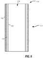
- an exemplary transfemoral delivery device 10 for a collapsible prosthetic heart valve(or other types of self-expanding collapsible stents) has a catheter assembly 16 for delivering the heart valve to and deploying the heart valve at a target location, and an operating handle 20 for controlling deployment of the valve from the catheter assembly.
- Delivery device 10extends from proximal end 12 ( FIG. 1B ) to atraumatic tip 14 at the distal end of catheter assembly 16.
- Catheter assembly 16is adapted to receive a collapsible prosthetic heart valve (not shown) in compartment 23 defined around inner shaft 26 and covered by distal sheath 24.
- Inner shaft 26may extend from operating handle 20 to atraumatic tip 14 of the delivery device, and includes retainer 25 affixed thereto at a spaced distance from tip 14 and adapted to hold a collapsible prosthetic valve in compartment 23.
- Retainer 25may have recesses 80 therein that are adapted to hold corresponding retention members of the valve. Details of the heart valve will be described in greater detail below with reference to FIG. 2 .
- Inner shaft 26may be made of a flexible material such as braided polyimide or polyetheretherketone (PEEK), for example. Using a material such as PEEK may improve the resistance of inner shaft 26 to kinking while catheter assembly 16 is tracking through the vasculature of a patient.
- PEEKpolyetheretherketone
- Distal sheath 24surrounds inner shaft 26 and is slidable relative to the inner shaft such that it can selectively cover or uncover compartment 23.
- Distal sheath 24is affixed at its proximal end to outer shaft 22, the proximal end of which is connected to operating handle 20.
- Distal end 27 of distal sheath 24abuts atraumatic tip 14 when the distal sheath is fully covering compartment 23, and is spaced apart from the atraumatic tip when compartment 23 is at least partially uncovered.
- Operating handle 20is adapted to control deployment of a prosthetic valve located in compartment 23 by permitting a user to selectively slide outer shaft 22 proximally or distally relative to inner shaft 26, thereby respectively uncovering or covering the compartment with distal sheath 24.
- operating handle 20is configured to repeatedly cover or uncover the compartment with distal sheath 24.
- compartment 23may be uncovered to expose a valve and allow it to expand at a target location. Once at the location, the functionality and positioning of the valve may be examined prior to complete release of the valve. If the functioning or position of the valve is improper, distal sheath 24 may be advanced to cover the compartment and the valve may be redeployed in a different position or orientation.
- outer shaft 22may be made of a flexible material such as nylon 11 or nylon 12, and it may have a round braid construction (i.e., round cross-section fibers braided together) or flat braid construction (i.e., rectangular cross-section fibers braided together), for example.
- the proximal end of inner shaft 26may be connected in substantially fixed relationship to outer housing 30 of operating handle 20, and the proximal end of outer shaft 22 may be affixed to carriage assembly 40 that is slidable along a longitudinal axis of the handle housing, such that a user can selectively slide the outer shaft relative to the inner shaft by sliding the carriage assembly relative to the handle housing.
- a hemostasis valve 28may be provided and may include an internal gasket adapted to create a seal between inner shaft 26 and the proximal end of outer shaft 22.
- Handle housing 30includes a top portion 30a and a bottom portion 30b.
- the top and bottom portions 30a and 30bmay be individual pieces joined to one another as shown in FIG. 1B .
- Collectively, top and bottom portions 30a and 30bdefine elongated space 34 in housing 30 in which carriage assembly 40 may travel.
- Elongated space 34preferably permits carriage assembly 40 to travel a distance that is at least as long as the anticipated length of the prosthetic valve to be delivered (e.g., at least about 50 mm), such that distal sheath 24 can be fully retracted from around the prosthetic valve.
- Carriage assembly 40may further include a pair of carriage grips 42 each attached to body portion 41 by a respective carriage grip shaft (not shown).
- Handle housing 30further defines a pocket 37 that extends through the top portion 30a and bottom portion 30b for receiving a deployment actuator 21.
- Deployment actuator 21is internally threaded for selective engagement with a threaded rod 45.
- rotation of the deployment actuator in one directioncauses the threaded rod to move proximally, at the same time pulling the body portion 41 of carriage assembly 40 proximally through elongated space 34, and pulling outer shaft 22 and distal sheath 24 proximally relative to inner shaft 26.
- FIG. 2shows a bioprosthetic valve 100 such as that described in U.S. Patent Publication No. 2012/0053681 .
- Prosthetic valve 100is designed to replace a native aortic valve.
- Valve 100has a collapsed condition and an expanded condition and may be formed from a collapsible framework or stent 102, with valve assembly 104 internally connected to the stent.
- Stent 102may be formed from any suitable biocompatible material, such as nitinol or any other suitable elastic or shape memory material, and may include annulus section 106, aortic section 108, and sinus section 110 located between the annulus section and the aortic section.
- Aortic section 108may have a larger cross-section than annulus section 106.
- Valve assembly 104includes a plurality of leaflets 112 and cuff 114 attached to stent 102.
- Leaflets 112 and cuff 114may be formed from a biocompatible polymer, from natural tissue such as bovine or porcine pericardial tissue, or from other appropriate biocompatible materials.
- Valve assembly 104is preferably connected to stent 102 generally within annulus section 106.
- a plurality of tabs or retainers 118may be spaced around one or both ends of stent 102 for engagement with recesses 80 of retainer 25, described above. Retainers 118 may also be utilized to collapse valve 100 for loading into delivery device 10.
- Valve 100is preferably stored in its expanded or open condition as bioprosthetic valve assembly 104 may be compromised by storage in a collapsed condition for extended periods of time. As such, it is necessary to crimp valve 100 into a collapsed condition of reduced cross-section for loading into delivery device 10 just prior to the surgical implantation procedure. In order to effectively limit the time period valve 100 is collapsed, the crimping process is preferably conducted in the operating arena by the surgeon, interventional cardiologist or surgical assistant using a specialized assembly.
- FIG. 3is a schematic representation of a human heart 300.
- the human heartincludes two atria and two ventricles: a right atrium 312 and a left atrium 322, and a right ventricle 314 and a left ventricle 324.
- heart 300further includes an aorta 310, and an aortic arch 320.
- aortic valve 330Disposed between left ventricle 324 and aorta 310 is aortic valve 330.
- pressurerises in left ventricle 324.
- aortic valve 330When the pressure in the left ventricle rises above the pressure in aorta 310, aortic valve 330 opens, allowing blood to exit left ventricle 324 into the aorta 310. When ventricular systole ends, pressure in left ventricle 324 rapidly drops. When the pressure in left ventricle 324 decreases, the aortic pressure forces aortic valve 330 to close. Blood flows through heart 300 in the direction shown by arrows "B".
- TFtransfemoral delivery of an aortic valve
- an incisionis made adjacent the hip and threaded up the femoral artery and around the aortic arch as shown.
- transapical deliverya small incision is made between the ribs and into the apex of the left ventricle 324 at position "P1" in heart wall 350 to deliver the prosthetic heart valve to the target site.
- a catheter with greater flexibility than conventional cathetersmay preferably be employed.
- outer shaft 410is formed of a generally cylindrical hypotube having proximal end 412 and distal end 414.
- Outer shaft 410may be formed of a metal, such as nitinol, Elgiloy, or stainless steel, or a biocompatible polymer.
- Outer shaft 410may have a size of approximately 24 French or less with outer wall 416 defining lumen 418 extending therethrough from proximal end 412 to distal end 414.
- outer wall 416Portions of outer wall 416 are removed to form cutouts 420, for example, by laser cutting. As shown in the enlargement of FIG. 4B , multiple cutouts 420 may be made to form a repeating pattern 419. For example, three cutouts 420a, 420b, 420c may be formed in outer wall 416 about the circumference of outer shaft 410, each cutout being spaced from adjacent cutouts by a distance s1 to form a discontinuous ring 421 about the circumference at a given longitudinal extent ( FIG. 4C ).
- ringis used to describe any number of cutouts aligned with one another about the circumference of a body, and is not limited to a single cutout that forms a complete circle about the circumference of the body.
- the number of cutouts 420 per ring 421may vary as desired and may include as few as one or two cutouts 420 or as many as four, five, six or more cutouts 420.
- rings 421may be formed along the length of outer shaft 410.
- rings 421are divided into two sets, a first set of rings 421a and a second set of rings 421b. Rings of the first set of rings 421a may all be aligned with one another along the length of outer shaft 410 as shown, and rings of the second set of rings 421b may be offset from the first set of rings 421a by a predetermined radial angle (e.g., offset by 90 degrees). Successive rings may be chosen such that the rings alternate between the two sets as shown. Though two sets are shown, it will be understood that the rings may be formed in any number of sets, for example, three, four or five sets, that are circumferentially offset from one another.
- each cutout 420includes an elongated portion 422 and a pair of teardrop portions 424 on opposing ends of the elongated portion 422.
- the combined length of the cutouts 420 around each ringmay make up between about 50% and about 90% of the circumference of outer shaft 410.
- cutouts 420are disposed perpendicular to the longitudinal axis of outer shaft 410.
- Teardrop portions 424may provide added flexion for outer shaft 410, while providing strain relief and maintain adequate compression resistance of outer shaft 410.
- each cutout 420includes a teardrop portion 424 at only one end of elongated portion 422.
- cutouts 420may include portions of other shapes such as triangles, circles, semicircles, or the like at one or both ends of elongated portion 422, instead of teardrop portions 424.
- cutouts 420may include a combination of shapes discussed above.
- the number of rings 421 cut into outer shaft 410may also be varied.
- outer shaft 410includes between about 40 and about 90 rings 421.
- the axial distance between adjacent rings 421may be between about 0.3 mm and about 1 mm. Rings 421 may be spaced from one another evenly or unevenly in the axial direction.
- Each ring 421may also include the same or a different number of cutouts 420. For example, a first ring may include only two cutouts, while an adjacent ring includes three cutouts.
- a similar or a different pattern of ringsmay also be laser cut into the distal sheath of a delivery device.
- the distal sheath and/or outer shaftmay be laser cut as shown to increase the flexibility of the delivery device over current devices of a similar size, while maintaining comparable compression resistance needed for resheathability.
- the wall having a plurality of cutoutscomparable compression strength is maintained while flexibility is increased.
- FIGS. 5A and 5Billustrate an embodiment of a distal sheath of a delivery device having improved flexibility over conventional distal sheaths.
- a pattern 519is cut into distal sheath 511 of a delivery device. It will be understood that the same or similar pattern may also be formed in the outer shaft of the delivery device or in both the distal sheath and the outer shaft.
- Distal sheath 511is formed of a generally cylindrical hypotube having proximal end 512 and distal end 514.
- Distal sheath 511may be formed of a metal, such as nitinol, Elgiloy, or stainless steel, or a biocompatible polymer.
- Distal sheath 511may have a size of approximately 24 French or less and may include outer wall 516 defining lumen 518 extending therethrough from proximal end 512 to distal end 514.
- cells 520may be cut in outer wall 516 of distal sheath 511 to form pattern 519 having a stent-like structure ( FIG. 5B ).
- struts 521remain about each cell 520, the struts being flexible and aiding in the maneuverability of distal sheath 511.
- certain cells 520may compress at portions of the distal sheath while other cells expand at other portions of the distal sheath when the distal sheath 511 is bent.
- cells 520are substantially diamond-shaped, with each cell being defined by four struts 521.
- the length of each cell in the axial direction of distal sheath 511is between about 0.5 mm and about 5 mm when distal sheath 511 is substantially straight.
- the number of cells formed in the distal sheathmay be varied. In some examples, three, four, five or six cells may be formed about the circumference of outer wall 516 at a given longitudinal extent of the distal sheath. Also, the number of rows of cells axially disposed along the length of distal sheath 511 may vary. Generally, the smaller the cells in the axial direction and the greater the number of rows of cells, the greater the amount of flexibility that will be imported to distal sheath 511.
- a polymer jacket 550may be added to the abluminal (i.e., outer) surface of outer wall 516 in order to increase the column strength of distal sheath 511 and prevent blood/debris from impinging on the valve ( FIG. 6 ).
- Polymer jacket 550may be formed of any suitable biocompatible polymer, including polyether block amide (e.g., PEBAX ®), nylons, polyester resins, urethanes or suitable combinations thereof.
- a non-polymeric materialmay also be used to form jacket 550.
- a liner 552such as a polytetrafluoroethylene (PTFE) liner, may be added to the luminal (i.e., inner) surface of outer wall 516 to add lubricity to portions of the outer wall 516 that may contact the heart valve in compartment 23 of the delivery device.
- PTFEpolytetrafluoroethylene
- the distal sheathafter a pattern is cut into outer wall 516 of distal sheath 511, the distal sheath still has enough column strength to be able to resheath a transcatheter aortic replacement valve while being flexible enough to traverse body tissue to the target location.
- the distal sheath 511in transfemoral delivery, is capable of more easily crossing the aortic arch and aligning with the native aortic annulus.
- Having distal sheath 511 formed of nitinol or another suitable material that is laser cut in this fashionprovides the requisite column strength and flexibility.
- wall 516may be made thinner compared to traditional braided constructions because the conventional braided wires overlap one another, adding to the overall wall thickness.
- FIGS. 7A and 7Billustrate the use of delivery device 700 having features of the present disclosure to deliver a medical device, such as a prosthetic heart valve, to an implant location.
- Delivery device 700may include all of the features discussed above with reference to FIGS. 1-3 and generally has proximal end 702 and distal end 704.
- Delivery device 700includes operating handle 706 for use by a physician or operator coupled at one side to outer shaft 710, which in turn extends to slidable distal sheath 712, forming compartment 714 therein for housing a prosthetic heart valve (not shown) disposed about an inner shaft (also not shown).
- the delivery device 700further includes a conical distal tip 716 at distal end 704. As shown in the enlargement of FIG.
- the laser cut pattern 719(e.g., the process of cutting cells 720 with struts 721) in distal sheath 714 allows the distal sheath to easily bend during use, making the implantation process easier and quicker.
- the same or a similar patternis cut into outer shaft 710 instead of, or in addition to, the pattern cut into distal sheath 714.
- FIG. 8is a comparison between a conventional distal sheath formed of braided construction and a laser-cut sheath formed with pattern 519 of FIGS. 5A and 5B .
- a three-point bend testwas performed on the two sheaths to displace a midpoint of each sheath between 0 and 1 centimetres (0 and 0.5 inches).
- the two end points of each sheathwere disposed about 8 centimetres (about 3 inches) apart.
- almost 4 Newtons (almost 0.9 pounds) of forceis required to displace the midpoint of a sheath of braided construction a distance of 1 centimetre (0.5 inches).
- the delivery systemhas been shown as a transfemoral delivery system, it will be understood that the teachings of the present disclosure are not so limited and that similar patterns may be cut into the outer sheath and/or distal sheath of transapical, transseptal or other delivery systems.
- the exampleshave been shown for a delivery system for transcatheter aortic valve replacement, the disclosed teachings are equally applicable for other valve replacement, such as, for example, mitral valve replacement, as well as for other catheters for valve replacement and/or repair.
- the present disclosuremay also be applied to catheters for other medical purposes, such as the implantation of stents and other medical devices, other types of percutaneous or laparoscopic surgical procedures and the like.
- the patternincludes a plurality of rings disposed along a longitudinal axis of the outer shaft or the distal sheath; and/or the plurality of rings may include a first set of rings having a first pattern and a second set of rings having a second pattern, the first pattern, the first set of rings being offset from the second pattern by a predetermined angle in the circumferential direction; and/or the first pattern may be offset from the second pattern by 90 degrees; and/or successive rings may alternate between a ring from the first set of rings and a ring from the second set of rings; and/or the at least one ring may include multiple discontinuous cutouts aligned with one another at a predetermined position along a longitudinal axis of the outer shaft in the distal sheath; and/or the at least one ring may include three discontinuous cutouts; and/or the at least one cutout may include an elongated portion and two teardrop portions on opposing ends of the elongated portion; and/or at least one of the outer shaft or the
- the plurality of polygonal cellsmay include diamond-shaped cells; and/or the pattern may be formed in the distal sheath; and/or may further include a liner disposed on a luminal surface of the distal sheath; and/or may further include a polymer jacket disposed on an abluminal surface of the distal sheath; and/or at least one of the outer shaft or the distal sheath may include stainless steel.
- cutting a patternmay include forming at least one cutout having an elongated portion and two teardrop portions on opposing ends of the elongated portion; and/or the at least one cutout may include a plurality of cutouts arranged in a ring; and/or cutting a pattern may include forming at least one polygonal cutout on an outer surface of at least one of the outer shaft and the distal sheath; and/or the at least one polygonal cutout may include a plurality of diamond-shaped cells.
Landscapes
- Health & Medical Sciences (AREA)
- Cardiology (AREA)
- Engineering & Computer Science (AREA)
- Heart & Thoracic Surgery (AREA)
- Transplantation (AREA)
- Biomedical Technology (AREA)
- Oral & Maxillofacial Surgery (AREA)
- Vascular Medicine (AREA)
- Life Sciences & Earth Sciences (AREA)
- Animal Behavior & Ethology (AREA)
- General Health & Medical Sciences (AREA)
- Public Health (AREA)
- Veterinary Medicine (AREA)
- Prostheses (AREA)
- Mechanical Engineering (AREA)
Description
- The present disclosure relates to delivery devices for implanting medical devices such as prosthetic heart valves and, more particularly, to assemblies and methods for forming delivery devices having greater flexibility.
- Prosthetic heart valves may be formed from biological materials such as harvested bovine valves or pericardial tissue. Such valves may include a valve assembly including one or more leaflets and a cuff or skirt, and are typically fitted within a stent, which may be inserted into the heart at the annulus of the compromised native valve to replace the native valve. To perform such an insertion procedure using a minimally invasive technique, it is typically necessary to compress the stent to a reduced diameter for loading into the delivery device.
- The delivery device having the prosthetic heart valve loaded therein is advanced through the patient's vasculature until it reaches the implantation site. Due to the size of the arteries and the tortuosity of the delivery route, it may be difficult to maneuver the delivery system to the implantation site. It would therefore be beneficial to provide a delivery device having a greater degree of flexibility that can more readily navigate tortuous paths. A delivery device disclosing all features of the introductory portion of
claim 1 is disclosed inWO 2012/023978 . - The invention as defined in
claim 1 provides a delivery device for a collapsible prosthetic heart valve includes an inner shaft having a proximal end and a distal end, an outer shaft disposed around the inner shaft and longitudinally moveable relative to the inner shaft, and a distal sheath affixed to the outer shaft at a proximal end thereof and disposed about a portion of the inner shaft and forming a compartment with the inner shaft, the compartment being adapted to receive the prosthetic heart valve so that the distal sheath covers the compartment, the distal shath being slidable relative to the inner shaft, the outer shaft having a pattern of cutouts formed therein, the pattern including at least one ring around a circumference of the outer shaft, the at least one ring having at least one of the cutouts. - The distal sheath may have a pattern of cutouts formed therein, the pattern including a plurality of polygonal cells extending through the distal sheath.
- As defined in
claim 12 the invention further provides a method of forming a delivery device for a collapsible prosthetic heart valve includes providing an inner shaft having a proximal end and a distal end, an outer shaft disposed about the inner shaft and being longitudinally moveable relative to the inner shaft, and a distal sheath affixed to the outer shaft at a proximal end thereof and disposed about a portion of the inner shaft and forming a compartment with the inner shaft, the compartment being adapted to receive the prosthetic heart valve so that the distal sheath covers the compartment, the distal sheath being slidable relative to the inner shaft, and cutting a pattern on the outer shaft at different axial extents. In one embodiment, the pattern is cut on the distal sheath at different axial extends. - Various embodiments of the present delivery device are disclosed herein with reference to the drawings, wherein:
FIG. 1A is a top plan view of a portion of an operating handle of a transfemoral delivery device for a collapsible prosthetic heart valve, shown with a partial longitudinal cross-section of the distal portion of a transfemoral catheter assembly;FIG. 1B is a side view of the handle ofFIG. 1A ;FIG. 2 is a perspective view of a self-expanding prosthetic heart valve;FIG. 3 is a schematic representation of a human heart showing transapical and transfemoral delivery approaches;FIGS. 4A and 4B are a perspective view and an enlarged partial developed view of an outer shaft having a laser cut pattern according to the present invention;FIG. 4C is a schematic representation illustrating the circumferential spacing of cutouts on an outer shaft according to the present invention;FIG. 4D is a schematic developed view of a cutout according to the present invention;FIGS. 5A and 5B are a front view and an enlarged partial view of a laser cut distal sheath according to the present disclosure;FIG. 6 is a schematic longitudinal cross-section of a distal sheath according to the present disclosure;FIG. 7A is a schematic top plan view showing the bending of a distal sheath;FIG. 7B is an enlarged partial view showing the bending of the struts of the distal sheath ofFIG. 7A ; andFIG. 8 is a three-point bend comparison of a conventional braided distal sheath and a distal sheath formed according to the present disclosure.- Embodiments of the presently disclosed delivery devices are described herein in detail with reference to the drawing figures, wherein like reference numerals identify similar or identical elements. In the description which follows, the term "proximal" refers to the end of a delivery device, or portion thereof, which is closest to the operator in use, while the term "distal" refers to the end of the delivery device, or portion thereof, which is farthest from the operator in use. Also as used herein, the terms "about," "generally" and "approximately" are intended to mean that slight deviations from absolute are included within the scope of the term so modified.
- Referring now to
FIGS. 1A-1B to illustrate the structure and function of the present invention, an exemplarytransfemoral delivery device 10 for a collapsible prosthetic heart valve (or other types of self-expanding collapsible stents) has acatheter assembly 16 for delivering the heart valve to and deploying the heart valve at a target location, and anoperating handle 20 for controlling deployment of the valve from the catheter assembly.Delivery device 10 extends from proximal end 12 (FIG. 1B ) to atraumatic tip 14 at the distal end ofcatheter assembly 16.Catheter assembly 16 is adapted to receive a collapsible prosthetic heart valve (not shown) incompartment 23 defined aroundinner shaft 26 and covered bydistal sheath 24. Inner shaft 26 may extend fromoperating handle 20 to atraumatic tip 14 of the delivery device, and includesretainer 25 affixed thereto at a spaced distance from tip 14 and adapted to hold a collapsible prosthetic valve incompartment 23.Retainer 25 may haverecesses 80 therein that are adapted to hold corresponding retention members of the valve. Details of the heart valve will be described in greater detail below with reference toFIG. 2 .Inner shaft 26 may be made of a flexible material such as braided polyimide or polyetheretherketone (PEEK), for example. Using a material such as PEEK may improve the resistance ofinner shaft 26 to kinking whilecatheter assembly 16 is tracking through the vasculature of a patient.Distal sheath 24 surroundsinner shaft 26 and is slidable relative to the inner shaft such that it can selectively cover or uncovercompartment 23.Distal sheath 24 is affixed at its proximal end toouter shaft 22, the proximal end of which is connected tooperating handle 20.Distal end 27 ofdistal sheath 24 abuts atraumatic tip 14 when the distal sheath is fully coveringcompartment 23, and is spaced apart from the atraumatic tip whencompartment 23 is at least partially uncovered.Operating handle 20 is adapted to control deployment of a prosthetic valve located incompartment 23 by permitting a user to selectively slideouter shaft 22 proximally or distally relative toinner shaft 26, thereby respectively uncovering or covering the compartment withdistal sheath 24. In some examples,operating handle 20 is configured to repeatedly cover or uncover the compartment withdistal sheath 24. For example,compartment 23 may be uncovered to expose a valve and allow it to expand at a target location. Once at the location, the functionality and positioning of the valve may be examined prior to complete release of the valve. If the functioning or position of the valve is improper,distal sheath 24 may be advanced to cover the compartment and the valve may be redeployed in a different position or orientation.- Typically,
outer shaft 22 may be made of a flexible material such as nylon 11 ornylon 12, and it may have a round braid construction (i.e., round cross-section fibers braided together) or flat braid construction (i.e., rectangular cross-section fibers braided together), for example. The proximal end ofinner shaft 26 may be connected in substantially fixed relationship toouter housing 30 ofoperating handle 20, and the proximal end ofouter shaft 22 may be affixed tocarriage assembly 40 that is slidable along a longitudinal axis of the handle housing, such that a user can selectively slide the outer shaft relative to the inner shaft by sliding the carriage assembly relative to the handle housing. Ahemostasis valve 28 may be provided and may include an internal gasket adapted to create a seal betweeninner shaft 26 and the proximal end ofouter shaft 22. Handle housing 30 includes atop portion 30a and abottom portion 30b. The top andbottom portions FIG. 1B . Collectively, top andbottom portions elongated space 34 inhousing 30 in whichcarriage assembly 40 may travel.Elongated space 34 preferably permitscarriage assembly 40 to travel a distance that is at least as long as the anticipated length of the prosthetic valve to be delivered (e.g., at least about 50 mm), such thatdistal sheath 24 can be fully retracted from around the prosthetic valve.Carriage assembly 40 may further include a pair of carriage grips 42 each attached tobody portion 41 by a respective carriage grip shaft (not shown).- Handle
housing 30 further defines apocket 37 that extends through thetop portion 30a andbottom portion 30b for receiving adeployment actuator 21.Deployment actuator 21 is internally threaded for selective engagement with a threadedrod 45. When thedeployment actuator 21 is in threaded engagement with the threaded rod, rotation of the deployment actuator in one direction (either clockwise or counterclockwise depending on the orientation of the threads on the threaded rod) causes the threaded rod to move proximally, at the same time pulling thebody portion 41 ofcarriage assembly 40 proximally through elongatedspace 34, and pullingouter shaft 22 anddistal sheath 24 proximally relative toinner shaft 26. Similarly, whendeployment actuator 21 is in threaded engagement with the threaded rod, rotation of the deployment actuator in the opposite direction causes the threaded rod to move distally, at the same time pushingbody portion 41 ofcarriage assembly 40 distally through elongatedspace 34, and pushingouter shaft 22 anddistal sheath 24 distally relative toinner shaft 26. FIG. 2 shows abioprosthetic valve 100 such as that described inU.S. Patent Publication No. 2012/0053681 .Prosthetic valve 100 is designed to replace a native aortic valve.Valve 100 has a collapsed condition and an expanded condition and may be formed from a collapsible framework orstent 102, withvalve assembly 104 internally connected to the stent.Stent 102 may be formed from any suitable biocompatible material, such as nitinol or any other suitable elastic or shape memory material, and may includeannulus section 106,aortic section 108, andsinus section 110 located between the annulus section and the aortic section.Aortic section 108 may have a larger cross-section thanannulus section 106.Valve assembly 104 includes a plurality ofleaflets 112 andcuff 114 attached tostent 102.Leaflets 112 andcuff 114 may be formed from a biocompatible polymer, from natural tissue such as bovine or porcine pericardial tissue, or from other appropriate biocompatible materials.Valve assembly 104 is preferably connected tostent 102 generally withinannulus section 106. A plurality of tabs orretainers 118 may be spaced around one or both ends ofstent 102 for engagement withrecesses 80 ofretainer 25, described above.Retainers 118 may also be utilized to collapsevalve 100 for loading intodelivery device 10.Valve 100 is preferably stored in its expanded or open condition asbioprosthetic valve assembly 104 may be compromised by storage in a collapsed condition for extended periods of time. As such, it is necessary to crimpvalve 100 into a collapsed condition of reduced cross-section for loading intodelivery device 10 just prior to the surgical implantation procedure. In order to effectively limit thetime period valve 100 is collapsed, the crimping process is preferably conducted in the operating arena by the surgeon, interventional cardiologist or surgical assistant using a specialized assembly.FIG. 3 is a schematic representation of ahuman heart 300. The human heart includes two atria and two ventricles: aright atrium 312 and aleft atrium 322, and aright ventricle 314 and aleft ventricle 324. As illustrated inFIG. 3 ,heart 300 further includes anaorta 310, and anaortic arch 320. Disposed betweenleft ventricle 324 andaorta 310 isaortic valve 330. During ventricular systole, pressure rises inleft ventricle 324. When the pressure in the left ventricle rises above the pressure inaorta 310,aortic valve 330 opens, allowing blood to exitleft ventricle 324 into theaorta 310. When ventricular systole ends, pressure inleft ventricle 324 rapidly drops. When the pressure inleft ventricle 324 decreases, the aortic pressure forcesaortic valve 330 to close. Blood flows throughheart 300 in the direction shown by arrows "B".- A dashed arrow, labeled "TF", indicates a transfemoral approach for treating or replacing heart tissue using a delivery device, such as that shown in
FIGS 1A-C . In transfemoral delivery of an aortic valve, an incision is made adjacent the hip and threaded up the femoral artery and around the aortic arch as shown. A dashed arrow, labeled "TA", indicates a transapical approach for treating or replacing heart tissue. In transapical delivery, a small incision is made between the ribs and into the apex of theleft ventricle 324 at position "P1" inheart wall 350 to deliver the prosthetic heart valve to the target site. In order to more easily advance a catheter to a target site using either of these approaches, or any other approach, a catheter with greater flexibility than conventional catheters may preferably be employed. - In order to increase the flexibility of the delivery system, an outer shaft of a delivery device in accordance with the invention is laser cut in a repeating pattern. As shown in
FIG. 4A ,outer shaft 410 is formed of a generally cylindrical hypotube havingproximal end 412 anddistal end 414.Outer shaft 410 may be formed of a metal, such as nitinol, Elgiloy, or stainless steel, or a biocompatible polymer.Outer shaft 410 may have a size of approximately 24 French or less withouter wall 416 defininglumen 418 extending therethrough fromproximal end 412 todistal end 414. - Portions of
outer wall 416 are removed to formcutouts 420, for example, by laser cutting. As shown in the enlargement ofFIG. 4B ,multiple cutouts 420 may be made to form arepeating pattern 419. For example, threecutouts outer wall 416 about the circumference ofouter shaft 410, each cutout being spaced from adjacent cutouts by a distance s1 to form adiscontinuous ring 421 about the circumference at a given longitudinal extent (FIG. 4C ). As used herein, the term "ring" is used to describe any number of cutouts aligned with one another about the circumference of a body, and is not limited to a single cutout that forms a complete circle about the circumference of the body. The number ofcutouts 420 perring 421 may vary as desired and may include as few as one or twocutouts 420 or as many as four, five, six ormore cutouts 420. Multiple rings 421 may be formed along the length ofouter shaft 410. In the example shown, rings 421 are divided into two sets, a first set ofrings 421a and a second set ofrings 421b. Rings of the first set ofrings 421a may all be aligned with one another along the length ofouter shaft 410 as shown, and rings of the second set ofrings 421b may be offset from the first set ofrings 421a by a predetermined radial angle (e.g., offset by 90 degrees). Successive rings may be chosen such that the rings alternate between the two sets as shown. Though two sets are shown, it will be understood that the rings may be formed in any number of sets, for example, three, four or five sets, that are circumferentially offset from one another.- Turning now to
FIG. 4D , the details ofcutouts 420 will be more fully described. As shown, eachcutout 420 includes anelongated portion 422 and a pair ofteardrop portions 424 on opposing ends of theelongated portion 422. The combined length of thecutouts 420 around each ring may make up between about 50% and about 90% of the circumference ofouter shaft 410. In this example,cutouts 420 are disposed perpendicular to the longitudinal axis ofouter shaft 410.Teardrop portions 424 may provide added flexion forouter shaft 410, while providing strain relief and maintain adequate compression resistance ofouter shaft 410. In some examples, eachcutout 420 includes ateardrop portion 424 at only one end ofelongated portion 422. In other examples,cutouts 420 may include portions of other shapes such as triangles, circles, semicircles, or the like at one or both ends ofelongated portion 422, instead ofteardrop portions 424. - Variations of the embodiment of
FIGS. 4A-4D are possible depending on the length and/or diameter of the outer shaft, the materials chosen for forming the shaft and other considerations. For example,cutouts 420 may include a combination of shapes discussed above. The number ofrings 421 cut intoouter shaft 410 may also be varied. In some examples,outer shaft 410 includes between about 40 and about 90 rings 421. Additionally, the axial distance betweenadjacent rings 421 may be between about 0.3 mm and about 1 mm.Rings 421 may be spaced from one another evenly or unevenly in the axial direction. Eachring 421 may also include the same or a different number ofcutouts 420. For example, a first ring may include only two cutouts, while an adjacent ring includes three cutouts. - Either the same, a similar or a different pattern of rings may also be laser cut into the distal sheath of a delivery device. Thus, the distal sheath and/or outer shaft may be laser cut as shown to increase the flexibility of the delivery device over current devices of a similar size, while maintaining comparable compression resistance needed for resheathability. Thus, by providing a continuous wall of an outer shaft from one end to the other, the wall having a plurality of cutouts, comparable compression strength is maintained while flexibility is increased.
FIGS. 5A and 5B illustrate an embodiment of a distal sheath of a delivery device having improved flexibility over conventional distal sheaths. In this example, apattern 519 is cut intodistal sheath 511 of a delivery device. It will be understood that the same or similar pattern may also be formed in the outer shaft of the delivery device or in both the distal sheath and the outer shaft.Distal sheath 511 is formed of a generally cylindrical hypotube havingproximal end 512 anddistal end 514.Distal sheath 511 may be formed of a metal, such as nitinol, Elgiloy, or stainless steel, or a biocompatible polymer.Distal sheath 511 may have a size of approximately 24 French or less and may includeouter wall 516 defininglumen 518 extending therethrough fromproximal end 512 todistal end 514.- Instead of forming
elongated cutouts 420, polygonal cutouts, hereinafter referred to ascells 520, may be cut inouter wall 516 ofdistal sheath 511 to formpattern 519 having a stent-like structure (FIG. 5B ). In formingcells 520, struts 521 remain about eachcell 520, the struts being flexible and aiding in the maneuverability ofdistal sheath 511. Thus,certain cells 520 may compress at portions of the distal sheath while other cells expand at other portions of the distal sheath when thedistal sheath 511 is bent. In one example,cells 520 are substantially diamond-shaped, with each cell being defined by fourstruts 521. In at least some examples, the length of each cell in the axial direction ofdistal sheath 511 is between about 0.5 mm and about 5 mm whendistal sheath 511 is substantially straight. The number of cells formed in the distal sheath may be varied. In some examples, three, four, five or six cells may be formed about the circumference ofouter wall 516 at a given longitudinal extent of the distal sheath. Also, the number of rows of cells axially disposed along the length ofdistal sheath 511 may vary. Generally, the smaller the cells in the axial direction and the greater the number of rows of cells, the greater the amount of flexibility that will be imported todistal sheath 511. - After cutting
pattern 519 intoouter wall 516 ofdistal sheath 511, apolymer jacket 550 may be added to the abluminal (i.e., outer) surface ofouter wall 516 in order to increase the column strength ofdistal sheath 511 and prevent blood/debris from impinging on the valve (FIG. 6 ).Polymer jacket 550 may be formed of any suitable biocompatible polymer, including polyether block amide (e.g., PEBAX ®), nylons, polyester resins, urethanes or suitable combinations thereof. A non-polymeric material may also be used to formjacket 550. Additionally, aliner 552, such as a polytetrafluoroethylene (PTFE) liner, may be added to the luminal (i.e., inner) surface ofouter wall 516 to add lubricity to portions of theouter wall 516 that may contact the heart valve incompartment 23 of the delivery device. - Thus, after a pattern is cut into
outer wall 516 ofdistal sheath 511, the distal sheath still has enough column strength to be able to resheath a transcatheter aortic replacement valve while being flexible enough to traverse body tissue to the target location. For example, in transfemoral delivery, thedistal sheath 511 is capable of more easily crossing the aortic arch and aligning with the native aortic annulus. Havingdistal sheath 511 formed of nitinol or another suitable material that is laser cut in this fashion provides the requisite column strength and flexibility. Additionally,wall 516 may be made thinner compared to traditional braided constructions because the conventional braided wires overlap one another, adding to the overall wall thickness. FIGS. 7A and 7B illustrate the use ofdelivery device 700 having features of the present disclosure to deliver a medical device, such as a prosthetic heart valve, to an implant location.Delivery device 700 may include all of the features discussed above with reference toFIGS. 1-3 and generally hasproximal end 702 anddistal end 704.Delivery device 700 includes operatinghandle 706 for use by a physician or operator coupled at one side toouter shaft 710, which in turn extends to slidabledistal sheath 712, formingcompartment 714 therein for housing a prosthetic heart valve (not shown) disposed about an inner shaft (also not shown). Thedelivery device 700 further includes a conicaldistal tip 716 atdistal end 704. As shown in the enlargement ofFIG. 7B , the laser cut pattern 719 (e.g., the process of cuttingcells 720 with struts 721) indistal sheath 714 allows the distal sheath to easily bend during use, making the implantation process easier and quicker. According to the invention the same or a similar pattern is cut intoouter shaft 710 instead of, or in addition to, the pattern cut intodistal sheath 714.FIG. 8 is a comparison between a conventional distal sheath formed of braided construction and a laser-cut sheath formed withpattern 519 ofFIGS. 5A and 5B . In this comparison, a three-point bend test was performed on the two sheaths to displace a midpoint of each sheath between 0 and 1 centimetres (0 and 0.5 inches). In this illustration, the two end points of each sheath were disposed about 8 centimetres (about 3 inches) apart. As seen from the comparison, almost 4 Newtons (almost 0.9 pounds) of force is required to displace the midpoint of a sheath of braided construction a distance of 1 centimetre (0.5 inches). Conversely, to displace the midpoint of a distal sheath having a laser-cut pattern 519 a distance of 1 centimetre (0.5 inches), less than 2 Newtons (less than 0.4 pounds) of force is required. Thus, the frame construction ofFIGS. 5A and 5B requires less than half of the force of the braided construction for a displacement of 1 centimetre (0.5 inches). This flexible construction reduces the risk of trauma to body tissue during delivery around tight turns.- Numerous modifications may be made to the illustrative embodiments and other arrangements may be devised without departing from the scope of the appended claims. For example, though the delivery system has been shown as a transfemoral delivery system, it will be understood that the teachings of the present disclosure are not so limited and that similar patterns may be cut into the outer sheath and/or distal sheath of transapical, transseptal or other delivery systems. Additionally, while the examples have been shown for a delivery system for transcatheter aortic valve replacement, the disclosed teachings are equally applicable for other valve replacement, such as, for example, mitral valve replacement, as well as for other catheters for valve replacement and/or repair. Moreover, the present disclosure may also be applied to catheters for other medical purposes, such as the implantation of stents and other medical devices, other types of percutaneous or laparoscopic surgical procedures and the like.
- (Deleted).
- In some examples, the pattern includes a plurality of rings disposed along a longitudinal axis of the outer shaft or the distal sheath; and/or the plurality of rings may include a first set of rings having a first pattern and a second set of rings having a second pattern, the first pattern, the first set of rings being offset from the second pattern by a predetermined angle in the circumferential direction; and/or the first pattern may be offset from the second pattern by 90 degrees; and/or successive rings may alternate between a ring from the first set of rings and a ring from the second set of rings; and/or the at least one ring may include multiple discontinuous cutouts aligned with one another at a predetermined position along a longitudinal axis of the outer shaft in the distal sheath; and/or the at least one ring may include three discontinuous cutouts; and/or the at least one cutout may include an elongated portion and two teardrop portions on opposing ends of the elongated portion; and/or at least one of the outer shaft or the distal sheath may include stainless steel.
- (Deleted)
- In some examples, the plurality of polygonal cells may include diamond-shaped cells; and/or the pattern may be formed in the distal sheath; and/or may further include a liner disposed on a luminal surface of the distal sheath; and/or may further include a polymer jacket disposed on an abluminal surface of the distal sheath; and/or at least one of the outer shaft or the distal sheath may include stainless steel.
- (Deleted)
- In some examples of the method of forming a delivery device, cutting a pattern may include forming at least one cutout having an elongated portion and two teardrop portions on opposing ends of the elongated portion; and/or the at least one cutout may include a plurality of cutouts arranged in a ring; and/or cutting a pattern may include forming at least one polygonal cutout on an outer surface of at least one of the outer shaft and the distal sheath; and/or the at least one polygonal cutout may include a plurality of diamond-shaped cells.
- It will be appreciated that the various dependent claims and the features set forth therein can be combined in different ways than presented in the initial claims. It will also be appreciated that the features described in connection with individual embodiments may be shared with others of the described embodiments.
Claims (15)
- A delivery device (10; 700) for a collapsible prosthetic heart valve (100) comprising:an inner shaft (26) having a proximal end and a distal end;an outer shaft (22; 410) disposed around the inner shaft and longitudinally moveable relative to the inner shaft (26); anda distal sheath (24; 511; 714) affixed to the outer shaft (22; 410) at a proximal end thereof and disposed about a portion of the inner shaft (26) and forming a compartment (23; 714) with the inner shaft (26), the compartment (23; 714) being adapted to receive the prosthetic heart valve (100) so that the distal sheath (24; 511; 714) covers the compartment (23; 714), the distal sheath (24; 511; 714) being slidable relative to the inner shaft (26);characterised by the outer shaft (22; 410) having a pattern of cutouts (420; 420a, 420b, 420c) formed therein, the pattern including at least one ring (421) around a circumference of the outer shaft (22; 410), the at least one ring (421) having at least one of the cutouts.
- The delivery device (10; 700) of claim 1, wherein the pattern includes a plurality of rings (421) disposed along a longitudinal axis of the outer shaft (22).
- The delivery device (10; 700) of claim 2, wherein the plurality of rings (421) include a first set of rings (421a) having a first pattern and a second set of rings (421b) having a second pattern, the first pattern, the first set of rings being offset from the second pattern by a predetermined angle in the circumferential direction, preferably wherein the first pattern is offset from the second pattern by 90 degrees, or wherein successive rings (421) alternate between a ring (421) from the first set of rings (421) and a ring from the second set of rings (421).
- The delivery device (10; 700) of claim 1, wherein the at least one ring (421) includes multiple discontinuous cutouts (420; 420a, 420b, 420c) aligned with one another at a predetermined position along a longitudinal axis of the outer shaft (22; 410), preferably wherein the at least one ring (410) includes two discontinuous cutouts (420; 420a, 420b, 420c).
- The delivery device (10; 700) of claim 1, wherein the at least one cutout (420; 420a, 420b, 420c) includes an elongated portion (422) and two teardrop portions (424) on opposing ends of the elongated portion (422).
- The delivery device (10; 700) of claim 1, wherein at least one of the outer shaft (22; 410) or the distal sheath (24; 511; 714) comprises stainless steel.
- The delivery device (10; 700) of claim 1, wherein the pattern including a plurality of polygonal cells (520; 720) extending through the outer shaft (22; 410).
- The delivery device (10; 700) of claim 1, wherein the plurality of polygonal cells (520; 720) include diamond-shaped cells.
- The delivery device (10; 700) of claim 7, further comprising a liner (552) disposed on a luminal surface of the distal sheath (24; 511; 714).
- The delivery device (10; 700) of claim 9, further comprising a polymer jacket disposed on an abluminal surface of the distal sheath (24; 511; 714).
- The delivery device (10; 700) of claim 7, wherein at least one of the outer shaft or the distal sheath (24; 511; 714) comprises stainless steel.
- A method of forming a delivery device (10; 700) for a collapsible prosthetic heart valve (100) according to claim 1 comprising: providing an inner shaft (26) having a proximal end and a distal end, an outer shaft (22; 410) disposed about the inner shaft (26) and being longitudinally moveable relative to the inner shaft (26), and a distal sheath (24; 511; 714) affixed to the outer shaft (22; 410) at a proximal end thereof and disposed about a portion of the inner shaft (26) and forming a compartment (23; 714) with the inner shaft 26), the compartment being adapted to receive the prosthetic heart valve so that the distal sheath covers the compartment, the distal sheath being slidable relative to the inner shaft; and cutting a pattern on the outer shaft at different axial extents.
- The method of claim 12, wherein cutting a pattern comprises forming at least one cutout (420; 420a, 420b, 420c) having an elongated portion (422) and two teardrop portions (424) on opposing ends of the elongated portion (422).
- The method of claim 13, wherein the at least one cutout (420; 420a, 420b, 420c) includes a plurality of cutouts (420; 420a, 420b, 420c) arranged in a ring (421).
- The method of claim 12, wherein cutting a pattern comprises forming at least one polygonal cutout (420; 420a, 420b, 420c) on an outer surface of the outer shaft (22; 410), preferably wherein the at least one polygonal cutout (420; 420a, 420b, 420c) includes a plurality of diamond-shaped cells (520; 720).
Applications Claiming Priority (1)
| Application Number | Priority Date | Filing Date | Title |
|---|---|---|---|
| US201462059228P | 2014-10-03 | 2014-10-03 |
Publications (2)
| Publication Number | Publication Date |
|---|---|
| EP3009103A1 EP3009103A1 (en) | 2016-04-20 |
| EP3009103B1true EP3009103B1 (en) | 2020-03-18 |
Family
ID=54251331
Family Applications (1)
| Application Number | Title | Priority Date | Filing Date |
|---|---|---|---|
| EP15187225.6ARevokedEP3009103B1 (en) | 2014-10-03 | 2015-09-28 | Flexible catheters and methods of forming same |
Country Status (3)
| Country | Link |
|---|---|
| US (1) | US10390950B2 (en) |
| EP (1) | EP3009103B1 (en) |
| ES (1) | ES2784721T3 (en) |
Cited By (15)
| Publication number | Priority date | Publication date | Assignee | Title |
|---|---|---|---|---|
| US10940001B2 (en) | 2012-05-30 | 2021-03-09 | Neovasc Tiara Inc. | Methods and apparatus for loading a prosthesis onto a delivery system |
| US11311376B2 (en) | 2019-06-20 | 2022-04-26 | Neovase Tiara Inc. | Low profile prosthetic mitral valve |
| US11357622B2 (en) | 2016-01-29 | 2022-06-14 | Neovase Tiara Inc. | Prosthetic valve for avoiding obstruction of outflow |
| US11389291B2 (en) | 2013-04-04 | 2022-07-19 | Neovase Tiara Inc. | Methods and apparatus for delivering a prosthetic valve to a beating heart |
| US11413139B2 (en) | 2011-11-23 | 2022-08-16 | Neovasc Tiara Inc. | Sequentially deployed transcatheter mitral valve prosthesis |
| US11419720B2 (en) | 2010-05-05 | 2022-08-23 | Neovasc Tiara Inc. | Transcatheter mitral valve prosthesis |
| US11464631B2 (en) | 2016-11-21 | 2022-10-11 | Neovasc Tiara Inc. | Methods and systems for rapid retraction of a transcatheter heart valve delivery system |
| US11491006B2 (en) | 2019-04-10 | 2022-11-08 | Neovasc Tiara Inc. | Prosthetic valve with natural blood flow |
| US11497602B2 (en) | 2012-02-14 | 2022-11-15 | Neovasc Tiara Inc. | Methods and apparatus for engaging a valve prosthesis with tissue |
| US11602429B2 (en) | 2019-04-01 | 2023-03-14 | Neovasc Tiara Inc. | Controllably deployable prosthetic valve |
| US11737872B2 (en) | 2018-11-08 | 2023-08-29 | Neovasc Tiara Inc. | Ventricular deployment of a transcatheter mitral valve prosthesis |
| US11779742B2 (en) | 2019-05-20 | 2023-10-10 | Neovasc Tiara Inc. | Introducer with hemostasis mechanism |
| US11793640B2 (en) | 2017-08-25 | 2023-10-24 | Neovasc Tiara Inc. | Sequentially deployed transcatheter mitral valve prosthesis |
| US11998447B2 (en) | 2019-03-08 | 2024-06-04 | Neovasc Tiara Inc. | Retrievable prosthesis delivery system |
| US12109111B2 (en) | 2015-12-15 | 2024-10-08 | Neovasc Tiara Inc. | Transseptal delivery system |
Families Citing this family (57)
| Publication number | Priority date | Publication date | Assignee | Title |
|---|---|---|---|---|
| US9572666B2 (en) | 2014-03-17 | 2017-02-21 | Evalve, Inc. | Mitral valve fixation device removal devices and methods |
| US9700445B2 (en) | 2014-11-04 | 2017-07-11 | Abbott Cardiovascular Systems, Inc. | One-way actuator knob |
| US10376673B2 (en) | 2015-06-19 | 2019-08-13 | Evalve, Inc. | Catheter guiding system and methods |
| US10736632B2 (en) | 2016-07-06 | 2020-08-11 | Evalve, Inc. | Methods and devices for valve clip excision |
| US11324495B2 (en) | 2016-07-29 | 2022-05-10 | Cephea Valve Technologies, Inc. | Systems and methods for delivering an intravascular device to the mitral annulus |
| US10661052B2 (en) | 2016-07-29 | 2020-05-26 | Cephea Valve Technologies, Inc. | Intravascular device delivery sheath |
| US10639151B2 (en) | 2016-07-29 | 2020-05-05 | Cephea Valve Technologies, Inc. | Threaded coil |
| US10974027B2 (en) | 2016-07-29 | 2021-04-13 | Cephea Valve Technologies, Inc. | Combination steerable catheter and systems |
| US10646689B2 (en) | 2016-07-29 | 2020-05-12 | Cephea Valve Technologies, Inc. | Mechanical interlock for catheters |
| US11045315B2 (en) | 2016-08-29 | 2021-06-29 | Cephea Valve Technologies, Inc. | Methods of steering and delivery of intravascular devices |
| US11109967B2 (en) | 2016-08-29 | 2021-09-07 | Cephea Valve Technologies, Inc. | Systems and methods for loading and deploying an intravascular device |
| US10933216B2 (en) | 2016-08-29 | 2021-03-02 | Cephea Valve Technologies, Inc. | Multilumen catheter |
| US10874512B2 (en) | 2016-10-05 | 2020-12-29 | Cephea Valve Technologies, Inc. | System and methods for delivering and deploying an artificial heart valve within the mitral annulus |
| US11071564B2 (en) | 2016-10-05 | 2021-07-27 | Evalve, Inc. | Cardiac valve cutting device |
| US10363138B2 (en) | 2016-11-09 | 2019-07-30 | Evalve, Inc. | Devices for adjusting the curvature of cardiac valve structures |
| US10653523B2 (en) | 2017-01-19 | 2020-05-19 | 4C Medical Technologies, Inc. | Systems, methods and devices for delivery systems, methods and devices for implanting prosthetic heart valves |
| US10716667B2 (en) | 2017-01-20 | 2020-07-21 | Medtronic Vascular, Inc. | Transcatheter delivery systems and delivery catheters for prosthetic mitral valve delivery, and methods for prosthetic mitral valve delivery using a retrograde approach |
| US10561495B2 (en) | 2017-01-24 | 2020-02-18 | 4C Medical Technologies, Inc. | Systems, methods and devices for two-step delivery and implantation of prosthetic heart valve |
| US12029647B2 (en) | 2017-03-07 | 2024-07-09 | 4C Medical Technologies, Inc. | Systems, methods and devices for prosthetic heart valve with single valve leaflet |
| US12036113B2 (en) | 2017-06-14 | 2024-07-16 | 4C Medical Technologies, Inc. | Delivery of heart chamber prosthetic valve implant |
| WO2019195860A2 (en) | 2018-04-04 | 2019-10-10 | Vdyne, Llc | Devices and methods for anchoring transcatheter heart valve |
| US11857441B2 (en) | 2018-09-04 | 2024-01-02 | 4C Medical Technologies, Inc. | Stent loading device |
| US11344413B2 (en) | 2018-09-20 | 2022-05-31 | Vdyne, Inc. | Transcatheter deliverable prosthetic heart valves and methods of delivery |
| US10321995B1 (en) | 2018-09-20 | 2019-06-18 | Vdyne, Llc | Orthogonally delivered transcatheter heart valve replacement |
| US11071627B2 (en) | 2018-10-18 | 2021-07-27 | Vdyne, Inc. | Orthogonally delivered transcatheter heart valve frame for valve in valve prosthesis |
| US11278437B2 (en) | 2018-12-08 | 2022-03-22 | Vdyne, Inc. | Compression capable annular frames for side delivery of transcatheter heart valve replacement |
| US12186187B2 (en) | 2018-09-20 | 2025-01-07 | Vdyne, Inc. | Transcatheter deliverable prosthetic heart valves and methods of delivery |
| US10595994B1 (en) | 2018-09-20 | 2020-03-24 | Vdyne, Llc | Side-delivered transcatheter heart valve replacement |
| US12102531B2 (en) | 2018-10-22 | 2024-10-01 | Evalve, Inc. | Tissue cutting systems, devices and methods |
| US11109969B2 (en) | 2018-10-22 | 2021-09-07 | Vdyne, Inc. | Guidewire delivery of transcatheter heart valve |
| US11724068B2 (en) | 2018-11-16 | 2023-08-15 | Cephea Valve Technologies, Inc. | Intravascular delivery system |
| US11253359B2 (en) | 2018-12-20 | 2022-02-22 | Vdyne, Inc. | Proximal tab for side-delivered transcatheter heart valves and methods of delivery |
| US10653522B1 (en) | 2018-12-20 | 2020-05-19 | Vdyne, Inc. | Proximal tab for side-delivered transcatheter heart valve prosthesis |
| WO2020146842A1 (en) | 2019-01-10 | 2020-07-16 | Vdyne, Llc | Anchor hook for side-delivery transcatheter heart valve prosthesis |
| US11273032B2 (en) | 2019-01-26 | 2022-03-15 | Vdyne, Inc. | Collapsible inner flow control component for side-deliverable transcatheter heart valve prosthesis |
| US11185409B2 (en) | 2019-01-26 | 2021-11-30 | Vdyne, Inc. | Collapsible inner flow control component for side-delivered transcatheter heart valve prosthesis |
| WO2020181154A2 (en) | 2019-03-05 | 2020-09-10 | Vdyne, Inc. | Tricuspid regurgitation control devices for orthogonal transcatheter heart valve prosthesis |
| US10758346B1 (en) | 2019-03-14 | 2020-09-01 | Vdyne, Inc. | A2 clip for side-delivered transcatheter mitral valve prosthesis |
| US11076956B2 (en) | 2019-03-14 | 2021-08-03 | Vdyne, Inc. | Proximal, distal, and anterior anchoring tabs for side-delivered transcatheter mitral valve prosthesis |
| US10631983B1 (en) | 2019-03-14 | 2020-04-28 | Vdyne, Inc. | Distal subannular anchoring tab for side-delivered transcatheter valve prosthesis |
| US11173027B2 (en) | 2019-03-14 | 2021-11-16 | Vdyne, Inc. | Side-deliverable transcatheter prosthetic valves and methods for delivering and anchoring the same |
| US11452628B2 (en) | 2019-04-15 | 2022-09-27 | 4C Medical Technologies, Inc. | Loading systems for collapsible prosthetic heart valve devices and methods thereof |
| CA3138875A1 (en) | 2019-05-04 | 2020-11-12 | Vdyne, Inc. | Cinch device and method for deployment of a side-delivered prosthetic heart valve in a native annulus |
| EP4480458A3 (en) | 2019-08-20 | 2025-04-09 | Vdyne, Inc. | Delivery devices for side-deliverable transcatheter prosthetic valves |
| CN120531525A (en) | 2019-08-26 | 2025-08-26 | 维迪内股份有限公司 | Laterally deliverable transcatheter prosthetic valve and method for its delivery and anchoring |
| US11234813B2 (en) | 2020-01-17 | 2022-02-01 | Vdyne, Inc. | Ventricular stability elements for side-deliverable prosthetic heart valves and methods of delivery |
| US12133797B2 (en) | 2020-01-31 | 2024-11-05 | 4C Medical Technologies, Inc. | Prosthetic heart valve delivery system: paddle attachment feature |
| US11931253B2 (en) | 2020-01-31 | 2024-03-19 | 4C Medical Technologies, Inc. | Prosthetic heart valve delivery system: ball-slide attachment |
| US12053375B2 (en) | 2020-03-05 | 2024-08-06 | 4C Medical Technologies, Inc. | Prosthetic mitral valve with improved atrial and/or annular apposition and paravalvular leakage mitigation |
| US11992403B2 (en) | 2020-03-06 | 2024-05-28 | 4C Medical Technologies, Inc. | Devices, systems and methods for improving recapture of prosthetic heart valve device with stent frame having valve support with inwardly stent cells |
| US12414811B2 (en) | 2020-05-06 | 2025-09-16 | Evalve, Inc. | Devices and methods for leaflet cutting |
| US12171485B2 (en) | 2020-05-06 | 2024-12-24 | Evalve, Inc. | Systems and methods for leaflet cutting using a hook catheter |
| US12048448B2 (en) | 2020-05-06 | 2024-07-30 | Evalve, Inc. | Leaflet grasping and cutting device |
| US12171486B2 (en) | 2020-05-06 | 2024-12-24 | Evalve, Inc. | Devices and methods for clip separation |
| US12178444B2 (en) | 2020-05-06 | 2024-12-31 | Evalve, Inc. | Clip removal systems and methods |
| US11969347B2 (en) | 2020-05-13 | 2024-04-30 | Evalve, Inc. | Methods, systems, and devices for deploying an implant |
| WO2024097234A1 (en)* | 2022-11-02 | 2024-05-10 | Cephea Valve Technologies, Inc. | Intravascular delivery system |
Citations (19)
| Publication number | Priority date | Publication date | Assignee | Title |
|---|---|---|---|---|
| EP0812579A1 (en) | 1996-06-13 | 1997-12-17 | Nitinol Devices & Components Inc. | A stent assembly |
| US20020165600A1 (en) | 1999-11-19 | 2002-11-07 | Advanced Bio Prosthetic Surfaces, Ltd. | Guidewires and thin film catheter-sheaths and method of making same |
| US20050043711A1 (en) | 2003-05-27 | 2005-02-24 | Cardia, Inc. | Flexible center connection for occlusion device |
| US20050273151A1 (en) | 2004-06-04 | 2005-12-08 | John Fulkerson | Stent delivery system |
| EP1656963A1 (en) | 2004-11-10 | 2006-05-17 | Creganna Technologies Limited | Elongate tubular member for use in medical device shafts |
| WO2007035471A2 (en) | 2005-09-16 | 2007-03-29 | Sadra Medical, Inc. | Medical device delivery sheath |
| US20070168013A1 (en) | 2006-01-19 | 2007-07-19 | Myles Douglas | Vascular graft and deployment system |
| US20070208405A1 (en) | 2006-03-06 | 2007-09-06 | Boston Scientific Scimed, Inc. | Stent delivery catheter |
| GB2433700B (en) | 2005-01-20 | 2007-12-12 | Fraunhofer Ges Forschung | Catheter for the transvascular implantation of prosthetic heart valves |
| WO2007149841A2 (en) | 2006-06-20 | 2007-12-27 | Aortx, Inc. | Torque shaft and torque drive |
| US20080027561A1 (en) | 2006-07-31 | 2008-01-31 | Vladimir Mitelberg | Interventional medical device system having an elongation retarding portion and method of using the same |
| US20080065011A1 (en) | 2006-09-08 | 2008-03-13 | Philippe Marchand | Integrated heart valve delivery system |
| US20090171456A1 (en) | 2007-12-28 | 2009-07-02 | Kveen Graig L | Percutaneous heart valve, system, and method |
| US7780723B2 (en) | 2005-06-13 | 2010-08-24 | Edwards Lifesciences Corporation | Heart valve delivery system |
| WO2011035327A1 (en) | 2009-09-21 | 2011-03-24 | Medtronic Inc. | Stented transcatheter prosthetic heart valve delivery system and method |
| WO2012023978A2 (en) | 2010-08-17 | 2012-02-23 | St. Jude Medical, Inc. | Delivery system for collapsible heart valve |
| WO2012116368A2 (en) | 2011-02-25 | 2012-08-30 | Edwards Lifesciences Corporation | Prosthetic heart valve delivery apparatus |
| US8323241B2 (en) | 2009-06-24 | 2012-12-04 | Shifamed Holdings, Llc | Steerable medical delivery devices and methods of use |
| EP3072478A1 (en)* | 2013-11-18 | 2016-09-28 | Shanghai Microport Cardioflow Medtech Co., Ltd. | Outer loading tube for implant and implant conveying system |
Family Cites Families (24)
| Publication number | Priority date | Publication date | Assignee | Title |
|---|---|---|---|---|
| US4423730A (en) | 1982-03-01 | 1984-01-03 | Shelhigh Inc. | Atriotomy button and implantation device |
| US5190546A (en) | 1983-10-14 | 1993-03-02 | Raychem Corporation | Medical devices incorporating SIM alloy elements |
| US5797960A (en) | 1993-02-22 | 1998-08-25 | Stevens; John H. | Method and apparatus for thoracoscopic intracardiac procedures |
| DE69435312D1 (en) | 1993-12-03 | 2010-10-14 | Edwards Lifesciences Ag | Cardiopulmonary bypass for closed chest surgery |
| US5968068A (en) | 1996-09-12 | 1999-10-19 | Baxter International Inc. | Endovascular delivery system |
| DE10026307A1 (en) | 2000-05-26 | 2001-11-29 | Variomed Ag Balzers | Stent, positioning element and insertion catheter |
| US20060142848A1 (en) | 2000-09-12 | 2006-06-29 | Shlomo Gabbay | Extra-anatomic aortic valve placement |
| US20060106415A1 (en) | 2004-11-12 | 2006-05-18 | Shlomo Gabbay | Apparatus to facilitate implantation |
| EP1788955A4 (en) | 2004-02-06 | 2011-02-02 | Childrens Medical Center | DEPLOYMENT DEVICE FOR CARDIAC SURGERY |
| GB0409691D0 (en)* | 2004-04-30 | 2004-06-02 | Titech Visionsort As | Apparatus and method |
| US20070162100A1 (en) | 2006-01-10 | 2007-07-12 | Shlomo Gabbay | System and method for loading implanter with prosthesis |
| US20060167468A1 (en) | 2004-11-12 | 2006-07-27 | Shlomo Gabbay | Implantation system and method for loading an implanter with a prosthesis |
| US20070073391A1 (en) | 2005-09-28 | 2007-03-29 | Henry Bourang | System and method for delivering a mitral valve repair device |
| US8167932B2 (en) | 2005-10-18 | 2012-05-01 | Edwards Lifesciences Corporation | Heart valve delivery system with valve catheter |
| US8764820B2 (en) | 2005-11-16 | 2014-07-01 | Edwards Lifesciences Corporation | Transapical heart valve delivery system and method |
| US8147541B2 (en) | 2006-02-27 | 2012-04-03 | Aortx, Inc. | Methods and devices for delivery of prosthetic heart valves and other prosthetics |
| US20110224678A1 (en) | 2006-03-23 | 2011-09-15 | Shlomo Gabbay | Method and implantation system for implanting a cardiovascular prosthesis |
| US20070239271A1 (en) | 2006-04-10 | 2007-10-11 | Than Nguyen | Systems and methods for loading a prosthesis onto a minimally invasive delivery system |
| US8070799B2 (en) | 2006-12-19 | 2011-12-06 | Sorin Biomedica Cardio S.R.L. | Instrument and method for in situ deployment of cardiac valve prostheses |
| EP2367504B1 (en) | 2008-10-30 | 2014-08-06 | St. Jude Medical, Inc. | Collapsible/expandable prosthetic heart valve delivery system and methods |
| EP3181074A1 (en) | 2009-01-30 | 2017-06-21 | St. Jude Medical, Inc. | Transapical mini-introducer homeostasis valve and punch |
| US9039759B2 (en) | 2010-08-24 | 2015-05-26 | St. Jude Medical, Cardiology Division, Inc. | Repositioning of prosthetic heart valve and deployment |
| EP2999436B1 (en)* | 2013-05-20 | 2018-08-29 | Edwards Lifesciences Corporation | Prosthetic heart valve delivery apparatus |
| GB2536690B (en) | 2015-03-26 | 2017-05-10 | Cook Medical Technologies Llc | Medical ablation system and method with reduced stray heating |
- 2015
- 2015-09-24USUS14/863,514patent/US10390950B2/enactiveActive
- 2015-09-28ESES15187225Tpatent/ES2784721T3/enactiveActive
- 2015-09-28EPEP15187225.6Apatent/EP3009103B1/ennot_activeRevoked
Patent Citations (22)
| Publication number | Priority date | Publication date | Assignee | Title |
|---|---|---|---|---|
| EP0812579A1 (en) | 1996-06-13 | 1997-12-17 | Nitinol Devices & Components Inc. | A stent assembly |
| US20020165600A1 (en) | 1999-11-19 | 2002-11-07 | Advanced Bio Prosthetic Surfaces, Ltd. | Guidewires and thin film catheter-sheaths and method of making same |
| US20050043711A1 (en) | 2003-05-27 | 2005-02-24 | Cardia, Inc. | Flexible center connection for occlusion device |
| US20050273151A1 (en) | 2004-06-04 | 2005-12-08 | John Fulkerson | Stent delivery system |
| EP1656963A1 (en) | 2004-11-10 | 2006-05-17 | Creganna Technologies Limited | Elongate tubular member for use in medical device shafts |
| GB2433700B (en) | 2005-01-20 | 2007-12-12 | Fraunhofer Ges Forschung | Catheter for the transvascular implantation of prosthetic heart valves |
| US20140214153A1 (en) | 2005-01-20 | 2014-07-31 | Jenavalve Technology Gmbh | Methods of implanting an endoprosthesis |
| US7780723B2 (en) | 2005-06-13 | 2010-08-24 | Edwards Lifesciences Corporation | Heart valve delivery system |
| WO2007035471A2 (en) | 2005-09-16 | 2007-03-29 | Sadra Medical, Inc. | Medical device delivery sheath |
| US20080188928A1 (en) | 2005-09-16 | 2008-08-07 | Amr Salahieh | Medical device delivery sheath |
| US20070168013A1 (en) | 2006-01-19 | 2007-07-19 | Myles Douglas | Vascular graft and deployment system |
| US20070208405A1 (en) | 2006-03-06 | 2007-09-06 | Boston Scientific Scimed, Inc. | Stent delivery catheter |
| WO2007149841A2 (en) | 2006-06-20 | 2007-12-27 | Aortx, Inc. | Torque shaft and torque drive |
| US20080027561A1 (en) | 2006-07-31 | 2008-01-31 | Vladimir Mitelberg | Interventional medical device system having an elongation retarding portion and method of using the same |
| US20080065011A1 (en) | 2006-09-08 | 2008-03-13 | Philippe Marchand | Integrated heart valve delivery system |
| US20090171456A1 (en) | 2007-12-28 | 2009-07-02 | Kveen Graig L | Percutaneous heart valve, system, and method |
| US8323241B2 (en) | 2009-06-24 | 2012-12-04 | Shifamed Holdings, Llc | Steerable medical delivery devices and methods of use |
| WO2011035327A1 (en) | 2009-09-21 | 2011-03-24 | Medtronic Inc. | Stented transcatheter prosthetic heart valve delivery system and method |
| US8562673B2 (en) | 2009-09-21 | 2013-10-22 | Medtronic, Inc. | Stented transcatheter prosthetic heart valve delivery system and method |
| WO2012023978A2 (en) | 2010-08-17 | 2012-02-23 | St. Jude Medical, Inc. | Delivery system for collapsible heart valve |
| WO2012116368A2 (en) | 2011-02-25 | 2012-08-30 | Edwards Lifesciences Corporation | Prosthetic heart valve delivery apparatus |
| EP3072478A1 (en)* | 2013-11-18 | 2016-09-28 | Shanghai Microport Cardioflow Medtech Co., Ltd. | Outer loading tube for implant and implant conveying system |
Cited By (23)
| Publication number | Priority date | Publication date | Assignee | Title |
|---|---|---|---|---|
| US11419720B2 (en) | 2010-05-05 | 2022-08-23 | Neovasc Tiara Inc. | Transcatheter mitral valve prosthesis |
| US11413139B2 (en) | 2011-11-23 | 2022-08-16 | Neovasc Tiara Inc. | Sequentially deployed transcatheter mitral valve prosthesis |
| US12053369B2 (en) | 2011-11-23 | 2024-08-06 | Neovasc Tiara Inc. | Sequentially deployed transcatheter mitral valve prosthesis |
| US12138159B2 (en) | 2012-02-14 | 2024-11-12 | Neovasc Tiara Inc. | Methods and apparatus for engaging a valve prosthesis with tissue |
| US11497602B2 (en) | 2012-02-14 | 2022-11-15 | Neovasc Tiara Inc. | Methods and apparatus for engaging a valve prosthesis with tissue |
| US10940001B2 (en) | 2012-05-30 | 2021-03-09 | Neovasc Tiara Inc. | Methods and apparatus for loading a prosthesis onto a delivery system |
| US11389294B2 (en) | 2012-05-30 | 2022-07-19 | Neovasc Tiara Inc. | Methods and apparatus for loading a prosthesis onto a delivery system |
| US11617650B2 (en) | 2012-05-30 | 2023-04-04 | Neovasc Tiara Inc. | Methods and apparatus for loading a prosthesis onto a delivery system |
| US11389291B2 (en) | 2013-04-04 | 2022-07-19 | Neovase Tiara Inc. | Methods and apparatus for delivering a prosthetic valve to a beating heart |
| US12109111B2 (en) | 2015-12-15 | 2024-10-08 | Neovasc Tiara Inc. | Transseptal delivery system |
| US12193932B2 (en) | 2016-01-29 | 2025-01-14 | Neovasc Tiara Inc. | Prosthetic valve for avoiding obstruction of outflow |
| US11357622B2 (en) | 2016-01-29 | 2022-06-14 | Neovase Tiara Inc. | Prosthetic valve for avoiding obstruction of outflow |
| US11464631B2 (en) | 2016-11-21 | 2022-10-11 | Neovasc Tiara Inc. | Methods and systems for rapid retraction of a transcatheter heart valve delivery system |
| US12201524B2 (en) | 2016-11-21 | 2025-01-21 | Neovasc Tiara Inc. | Methods and systems for rapid retraction of a transcatheter heart valve delivery system |
| US11793640B2 (en) | 2017-08-25 | 2023-10-24 | Neovasc Tiara Inc. | Sequentially deployed transcatheter mitral valve prosthesis |
| US11737872B2 (en) | 2018-11-08 | 2023-08-29 | Neovasc Tiara Inc. | Ventricular deployment of a transcatheter mitral valve prosthesis |
| US11998447B2 (en) | 2019-03-08 | 2024-06-04 | Neovasc Tiara Inc. | Retrievable prosthesis delivery system |
| US11602429B2 (en) | 2019-04-01 | 2023-03-14 | Neovasc Tiara Inc. | Controllably deployable prosthetic valve |
| US12036117B2 (en) | 2019-04-10 | 2024-07-16 | Neovasc Tiara Inc. | Prosthetic valve with natural blood flow |
| US11491006B2 (en) | 2019-04-10 | 2022-11-08 | Neovasc Tiara Inc. | Prosthetic valve with natural blood flow |
| US11779742B2 (en) | 2019-05-20 | 2023-10-10 | Neovasc Tiara Inc. | Introducer with hemostasis mechanism |
| US11931254B2 (en) | 2019-06-20 | 2024-03-19 | Neovasc Tiara Inc. | Low profile prosthetic mitral valve |
| US11311376B2 (en) | 2019-06-20 | 2022-04-26 | Neovase Tiara Inc. | Low profile prosthetic mitral valve |
Also Published As
| Publication number | Publication date |
|---|---|
| EP3009103A1 (en) | 2016-04-20 |
| ES2784721T3 (en) | 2020-09-30 |
| US20160095703A1 (en) | 2016-04-07 |
| US10390950B2 (en) | 2019-08-27 |
Similar Documents
| Publication | Publication Date | Title |
|---|---|---|
| EP3009103B1 (en) | Flexible catheters and methods of forming same | |
| US10751177B2 (en) | Flexible catheter and methods of forming same | |
| US20250041089A1 (en) | Heart valve prosthesis delivery system and method for delivery of heart valve prosthesis with introducer sheath | |
| US11883287B2 (en) | Steerable rail delivery system | |
| US10932905B2 (en) | Introducer sheath having expandable portions | |
| US10850064B2 (en) | Introducer sheath having expandable portions | |
| US9700411B2 (en) | Delivery system for collapsible heart valve | |
| US10130470B2 (en) | Sleeve for facilitating movement of a transfemoral catheter | |
| CN113747859A (en) | Annuloplasty ring with posterior leaflet for minimally invasive treatment | |
| US20240299164A1 (en) | Prosthetic valve delivery apparatus with strain relief nosecone | |
| EP3977963B1 (en) | Transfer sleeve for use with a medical device delivery system | |
| CN115461016A (en) | Transcatheter valve leaflet replacement devices, delivery, guidance and fixation systems and methods thereof | |
| US20250073024A1 (en) | Expandable frame for a prosthetic heart valve | |
| US20250186200A1 (en) | Leaflet Tissue Modification | |
| CN118251195A (en) | Valve prosthesis and transcatheter delivery system | |
| HK40029712B (en) | Steerable rail delivery system |
Legal Events
| Date | Code | Title | Description |
|---|---|---|---|
| PUAI | Public reference made under article 153(3) epc to a published international application that has entered the european phase | Free format text:ORIGINAL CODE: 0009012 | |
| AK | Designated contracting states | Kind code of ref document:A1 Designated state(s):AL AT BE BG CH CY CZ DE DK EE ES FI FR GB GR HR HU IE IS IT LI LT LU LV MC MK MT NL NO PL PT RO RS SE SI SK SM TR | |
| AX | Request for extension of the european patent | Extension state:BA ME | |
| 17P | Request for examination filed | Effective date:20160930 | |
| STAA | Information on the status of an ep patent application or granted ep patent | Free format text:STATUS: EXAMINATION IS IN PROGRESS | |
| 17Q | First examination report despatched | Effective date:20161201 | |
| RIC1 | Information provided on ipc code assigned before grant | Ipc:A61F 2/966 20130101ALN20190813BHEP Ipc:A61F 2/24 20060101AFI20190813BHEP | |
| GRAP | Despatch of communication of intention to grant a patent | Free format text:ORIGINAL CODE: EPIDOSNIGR1 | |
| STAA | Information on the status of an ep patent application or granted ep patent | Free format text:STATUS: GRANT OF PATENT IS INTENDED | |
| RIC1 | Information provided on ipc code assigned before grant | Ipc:A61F 2/966 20130101ALN20190925BHEP Ipc:A61F 2/24 20060101AFI20190925BHEP | |
| INTG | Intention to grant announced | Effective date:20191016 | |
| RIN1 | Information on inventor provided before grant (corrected) | Inventor name:THOMAS, RALPH JOSEPH Inventor name:KHOUENGBOUA, SOUNTHARA Inventor name:HILLUKKA, BRETT ALLEN Inventor name:BENSON, THOMAS MARK | |
| GRAS | Grant fee paid | Free format text:ORIGINAL CODE: EPIDOSNIGR3 | |
| GRAA | (expected) grant | Free format text:ORIGINAL CODE: 0009210 | |
| STAA | Information on the status of an ep patent application or granted ep patent | Free format text:STATUS: THE PATENT HAS BEEN GRANTED | |
| AK | Designated contracting states | Kind code of ref document:B1 Designated state(s):AL AT BE BG CH CY CZ DE DK EE ES FI FR GB GR HR HU IE IS IT LI LT LU LV MC MK MT NL NO PL PT RO RS SE SI SK SM TR | |
| REG | Reference to a national code | Ref country code:GB Ref legal event code:FG4D | |
| REG | Reference to a national code | Ref country code:DE Ref legal event code:R096 Ref document number:602015048903 Country of ref document:DE | |
| REG | Reference to a national code | Ref country code:AT Ref legal event code:REF Ref document number:1245037 Country of ref document:AT Kind code of ref document:T Effective date:20200415 Ref country code:IE Ref legal event code:FG4D | |
| PG25 | Lapsed in a contracting state [announced via postgrant information from national office to epo] | Ref country code:FI Free format text:LAPSE BECAUSE OF FAILURE TO SUBMIT A TRANSLATION OF THE DESCRIPTION OR TO PAY THE FEE WITHIN THE PRESCRIBED TIME-LIMIT Effective date:20200318 Ref country code:NO Free format text:LAPSE BECAUSE OF FAILURE TO SUBMIT A TRANSLATION OF THE DESCRIPTION OR TO PAY THE FEE WITHIN THE PRESCRIBED TIME-LIMIT Effective date:20200618 Ref country code:RS Free format text:LAPSE BECAUSE OF FAILURE TO SUBMIT A TRANSLATION OF THE DESCRIPTION OR TO PAY THE FEE WITHIN THE PRESCRIBED TIME-LIMIT Effective date:20200318 | |
| REG | Reference to a national code | Ref country code:NL Ref legal event code:MP Effective date:20200318 | |
| PG25 | Lapsed in a contracting state [announced via postgrant information from national office to epo] | Ref country code:GR Free format text:LAPSE BECAUSE OF FAILURE TO SUBMIT A TRANSLATION OF THE DESCRIPTION OR TO PAY THE FEE WITHIN THE PRESCRIBED TIME-LIMIT Effective date:20200619 Ref country code:BG Free format text:LAPSE BECAUSE OF FAILURE TO SUBMIT A TRANSLATION OF THE DESCRIPTION OR TO PAY THE FEE WITHIN THE PRESCRIBED TIME-LIMIT Effective date:20200618 Ref country code:LV Free format text:LAPSE BECAUSE OF FAILURE TO SUBMIT A TRANSLATION OF THE DESCRIPTION OR TO PAY THE FEE WITHIN THE PRESCRIBED TIME-LIMIT Effective date:20200318 Ref country code:SE Free format text:LAPSE BECAUSE OF FAILURE TO SUBMIT A TRANSLATION OF THE DESCRIPTION OR TO PAY THE FEE WITHIN THE PRESCRIBED TIME-LIMIT Effective date:20200318 Ref country code:HR Free format text:LAPSE BECAUSE OF FAILURE TO SUBMIT A TRANSLATION OF THE DESCRIPTION OR TO PAY THE FEE WITHIN THE PRESCRIBED TIME-LIMIT Effective date:20200318 | |
| REG | Reference to a national code | Ref country code:LT Ref legal event code:MG4D | |
| PG25 | Lapsed in a contracting state [announced via postgrant information from national office to epo] | Ref country code:NL Free format text:LAPSE BECAUSE OF FAILURE TO SUBMIT A TRANSLATION OF THE DESCRIPTION OR TO PAY THE FEE WITHIN THE PRESCRIBED TIME-LIMIT Effective date:20200318 | |
| REG | Reference to a national code | Ref country code:ES Ref legal event code:FG2A Ref document number:2784721 Country of ref document:ES Kind code of ref document:T3 Effective date:20200930 | |
| PG25 | Lapsed in a contracting state [announced via postgrant information from national office to epo] | Ref country code:SK Free format text:LAPSE BECAUSE OF FAILURE TO SUBMIT A TRANSLATION OF THE DESCRIPTION OR TO PAY THE FEE WITHIN THE PRESCRIBED TIME-LIMIT Effective date:20200318 Ref country code:IS Free format text:LAPSE BECAUSE OF FAILURE TO SUBMIT A TRANSLATION OF THE DESCRIPTION OR TO PAY THE FEE WITHIN THE PRESCRIBED TIME-LIMIT Effective date:20200718 Ref country code:SM Free format text:LAPSE BECAUSE OF FAILURE TO SUBMIT A TRANSLATION OF THE DESCRIPTION OR TO PAY THE FEE WITHIN THE PRESCRIBED TIME-LIMIT Effective date:20200318 Ref country code:PT Free format text:LAPSE BECAUSE OF FAILURE TO SUBMIT A TRANSLATION OF THE DESCRIPTION OR TO PAY THE FEE WITHIN THE PRESCRIBED TIME-LIMIT Effective date:20200812 Ref country code:EE Free format text:LAPSE BECAUSE OF FAILURE TO SUBMIT A TRANSLATION OF THE DESCRIPTION OR TO PAY THE FEE WITHIN THE PRESCRIBED TIME-LIMIT Effective date:20200318 Ref country code:RO Free format text:LAPSE BECAUSE OF FAILURE TO SUBMIT A TRANSLATION OF THE DESCRIPTION OR TO PAY THE FEE WITHIN THE PRESCRIBED TIME-LIMIT Effective date:20200318 Ref country code:LT Free format text:LAPSE BECAUSE OF FAILURE TO SUBMIT A TRANSLATION OF THE DESCRIPTION OR TO PAY THE FEE WITHIN THE PRESCRIBED TIME-LIMIT Effective date:20200318 Ref country code:CZ Free format text:LAPSE BECAUSE OF FAILURE TO SUBMIT A TRANSLATION OF THE DESCRIPTION OR TO PAY THE FEE WITHIN THE PRESCRIBED TIME-LIMIT Effective date:20200318 | |
| REG | Reference to a national code | Ref country code:AT Ref legal event code:MK05 Ref document number:1245037 Country of ref document:AT Kind code of ref document:T Effective date:20200318 | |
| REG | Reference to a national code | Ref country code:DE Ref legal event code:R026 Ref document number:602015048903 Country of ref document:DE | |
| PLBI | Opposition filed | Free format text:ORIGINAL CODE: 0009260 | |
| PLAX | Notice of opposition and request to file observation + time limit sent | Free format text:ORIGINAL CODE: EPIDOSNOBS2 | |
| 26 | Opposition filed | Opponent name:EDWARDS LIFESCIENCES CORPORATION Effective date:20201217 Opponent name:MEDTRONIC INC. Effective date:20201218 | |
| PG25 | Lapsed in a contracting state [announced via postgrant information from national office to epo] | Ref country code:AT Free format text:LAPSE BECAUSE OF FAILURE TO SUBMIT A TRANSLATION OF THE DESCRIPTION OR TO PAY THE FEE WITHIN THE PRESCRIBED TIME-LIMIT Effective date:20200318 Ref country code:DK Free format text:LAPSE BECAUSE OF FAILURE TO SUBMIT A TRANSLATION OF THE DESCRIPTION OR TO PAY THE FEE WITHIN THE PRESCRIBED TIME-LIMIT Effective date:20200318 | |
| PG25 | Lapsed in a contracting state [announced via postgrant information from national office to epo] | Ref country code:PL Free format text:LAPSE BECAUSE OF FAILURE TO SUBMIT A TRANSLATION OF THE DESCRIPTION OR TO PAY THE FEE WITHIN THE PRESCRIBED TIME-LIMIT Effective date:20200318 | |
| PG25 | Lapsed in a contracting state [announced via postgrant information from national office to epo] | Ref country code:MC Free format text:LAPSE BECAUSE OF FAILURE TO SUBMIT A TRANSLATION OF THE DESCRIPTION OR TO PAY THE FEE WITHIN THE PRESCRIBED TIME-LIMIT Effective date:20200318 | |
| PLBB | Reply of patent proprietor to notice(s) of opposition received | Free format text:ORIGINAL CODE: EPIDOSNOBS3 | |
| PG25 | Lapsed in a contracting state [announced via postgrant information from national office to epo] | Ref country code:SI Free format text:LAPSE BECAUSE OF FAILURE TO SUBMIT A TRANSLATION OF THE DESCRIPTION OR TO PAY THE FEE WITHIN THE PRESCRIBED TIME-LIMIT Effective date:20200318 | |
| REG | Reference to a national code | Ref country code:BE Ref legal event code:MM Effective date:20200930 | |
| PG25 | Lapsed in a contracting state [announced via postgrant information from national office to epo] | Ref country code:LU Free format text:LAPSE BECAUSE OF NON-PAYMENT OF DUE FEES Effective date:20200928 | |
| PG25 | Lapsed in a contracting state [announced via postgrant information from national office to epo] | Ref country code:IE Free format text:LAPSE BECAUSE OF NON-PAYMENT OF DUE FEES Effective date:20200928 Ref country code:BE Free format text:LAPSE BECAUSE OF NON-PAYMENT OF DUE FEES Effective date:20200930 | |
| PG25 | Lapsed in a contracting state [announced via postgrant information from national office to epo] | Ref country code:TR Free format text:LAPSE BECAUSE OF FAILURE TO SUBMIT A TRANSLATION OF THE DESCRIPTION OR TO PAY THE FEE WITHIN THE PRESCRIBED TIME-LIMIT Effective date:20200318 Ref country code:MT Free format text:LAPSE BECAUSE OF FAILURE TO SUBMIT A TRANSLATION OF THE DESCRIPTION OR TO PAY THE FEE WITHIN THE PRESCRIBED TIME-LIMIT Effective date:20200318 Ref country code:CY Free format text:LAPSE BECAUSE OF FAILURE TO SUBMIT A TRANSLATION OF THE DESCRIPTION OR TO PAY THE FEE WITHIN THE PRESCRIBED TIME-LIMIT Effective date:20200318 | |
| PG25 | Lapsed in a contracting state [announced via postgrant information from national office to epo] | Ref country code:MK Free format text:LAPSE BECAUSE OF FAILURE TO SUBMIT A TRANSLATION OF THE DESCRIPTION OR TO PAY THE FEE WITHIN THE PRESCRIBED TIME-LIMIT Effective date:20200318 Ref country code:AL Free format text:LAPSE BECAUSE OF FAILURE TO SUBMIT A TRANSLATION OF THE DESCRIPTION OR TO PAY THE FEE WITHIN THE PRESCRIBED TIME-LIMIT Effective date:20200318 | |
| PGFP | Annual fee paid to national office [announced via postgrant information from national office to epo] | Ref country code:GB Payment date:20220810 Year of fee payment:8 Ref country code:DE Payment date:20220615 Year of fee payment:8 | |
| PGFP | Annual fee paid to national office [announced via postgrant information from national office to epo] | Ref country code:FR Payment date:20220810 Year of fee payment:8 | |
| PGFP | Annual fee paid to national office [announced via postgrant information from national office to epo] | Ref country code:IT Payment date:20220913 Year of fee payment:8 Ref country code:ES Payment date:20221011 Year of fee payment:8 | |
| PGFP | Annual fee paid to national office [announced via postgrant information from national office to epo] | Ref country code:CH Payment date:20221001 Year of fee payment:8 | |
| RDAF | Communication despatched that patent is revoked | Free format text:ORIGINAL CODE: EPIDOSNREV1 | |
| REG | Reference to a national code | Ref country code:DE Ref legal event code:R103 Ref document number:602015048903 Country of ref document:DE Ref country code:DE Ref legal event code:R064 Ref document number:602015048903 Country of ref document:DE | |
| RDAG | Patent revoked | Free format text:ORIGINAL CODE: 0009271 | |
| STAA | Information on the status of an ep patent application or granted ep patent | Free format text:STATUS: PATENT REVOKED | |
| P01 | Opt-out of the competence of the unified patent court (upc) registered | Effective date:20230616 | |
| REG | Reference to a national code | Ref country code:CH Ref legal event code:PL | |
| 27W | Patent revoked | Effective date:20230415 | |
| GBPR | Gb: patent revoked under art. 102 of the ep convention designating the uk as contracting state | Effective date:20230415 |