EP3006943B1 - Module for a laboratory sample distribution system, laboratory sample distribution system and laboratory automation system - Google Patents
Module for a laboratory sample distribution system, laboratory sample distribution system and laboratory automation systemDownload PDFInfo
- Publication number
- EP3006943B1 EP3006943B1EP14187891.8AEP14187891AEP3006943B1EP 3006943 B1EP3006943 B1EP 3006943B1EP 14187891 AEP14187891 AEP 14187891AEP 3006943 B1EP3006943 B1EP 3006943B1
- Authority
- EP
- European Patent Office
- Prior art keywords
- magnetic coupling
- module
- ferromagnetic
- modules
- sample container
- Prior art date
- Legal status (The legal status is an assumption and is not a legal conclusion. Google has not performed a legal analysis and makes no representation as to the accuracy of the status listed.)
- Active
Links
- 239000006101laboratory sampleSubstances0.000titleclaimsdescription58
- 230000005291magnetic effectEffects0.000claimsdescription139
- 230000008878couplingEffects0.000claimsdescription134
- 238000010168coupling processMethods0.000claimsdescription134
- 238000005859coupling reactionMethods0.000claimsdescription134
- 230000005294ferromagnetic effectEffects0.000claimsdescription95
- 239000000523sampleSubstances0.000claimsdescription60
- 239000000969carrierSubstances0.000claimsdescription31
- 239000000463materialSubstances0.000claimsdescription7
- 230000000295complement effectEffects0.000claimsdescription4
- XEEYBQQBJWHFJM-UHFFFAOYSA-NIronChemical compound[Fe]XEEYBQQBJWHFJM-UHFFFAOYSA-N0.000description2
- 239000008280bloodSubstances0.000description2
- 210000004369bloodAnatomy0.000description2
- 238000005119centrifugationMethods0.000description2
- 230000000717retained effectEffects0.000description2
- 239000012491analyteSubstances0.000description1
- 239000003153chemical reaction reagentSubstances0.000description1
- 230000003247decreasing effectEffects0.000description1
- 238000001514detection methodMethods0.000description1
- 230000000694effectsEffects0.000description1
- 230000020169heat generationEffects0.000description1
- 229910052742ironInorganic materials0.000description1
- 239000007788liquidSubstances0.000description1
- 230000003071parasitic effectEffects0.000description1
- 229920003023plasticPolymers0.000description1
- 238000012805post-processingMethods0.000description1
- 238000007781pre-processingMethods0.000description1
- 238000007789sealingMethods0.000description1
Images


Classifications
- G—PHYSICS
- G01—MEASURING; TESTING
- G01N—INVESTIGATING OR ANALYSING MATERIALS BY DETERMINING THEIR CHEMICAL OR PHYSICAL PROPERTIES
- G01N35/00—Automatic analysis not limited to methods or materials provided for in any single one of groups G01N1/00 - G01N33/00; Handling materials therefor
- G01N35/02—Automatic analysis not limited to methods or materials provided for in any single one of groups G01N1/00 - G01N33/00; Handling materials therefor using a plurality of sample containers moved by a conveyor system past one or more treatment or analysis stations
- G01N35/04—Details of the conveyor system
- B—PERFORMING OPERATIONS; TRANSPORTING
- B65—CONVEYING; PACKING; STORING; HANDLING THIN OR FILAMENTARY MATERIAL
- B65G—TRANSPORT OR STORAGE DEVICES, e.g. CONVEYORS FOR LOADING OR TIPPING, SHOP CONVEYOR SYSTEMS OR PNEUMATIC TUBE CONVEYORS
- B65G54/00—Non-mechanical conveyors not otherwise provided for
- B65G54/02—Non-mechanical conveyors not otherwise provided for electrostatic, electric, or magnetic
- G—PHYSICS
- G01—MEASURING; TESTING
- G01N—INVESTIGATING OR ANALYSING MATERIALS BY DETERMINING THEIR CHEMICAL OR PHYSICAL PROPERTIES
- G01N35/00—Automatic analysis not limited to methods or materials provided for in any single one of groups G01N1/00 - G01N33/00; Handling materials therefor
- B—PERFORMING OPERATIONS; TRANSPORTING
- B65—CONVEYING; PACKING; STORING; HANDLING THIN OR FILAMENTARY MATERIAL
- B65G—TRANSPORT OR STORAGE DEVICES, e.g. CONVEYORS FOR LOADING OR TIPPING, SHOP CONVEYOR SYSTEMS OR PNEUMATIC TUBE CONVEYORS
- B65G2201/00—Indexing codes relating to handling devices, e.g. conveyors, characterised by the type of product or load being conveyed or handled
- B65G2201/02—Articles
- B65G2201/0235—Containers
- B65G2201/0261—Puck as article support
- G—PHYSICS
- G01—MEASURING; TESTING
- G01N—INVESTIGATING OR ANALYSING MATERIALS BY DETERMINING THEIR CHEMICAL OR PHYSICAL PROPERTIES
- G01N35/00—Automatic analysis not limited to methods or materials provided for in any single one of groups G01N1/00 - G01N33/00; Handling materials therefor
- G01N2035/00178—Special arrangements of analysers
- G01N2035/00326—Analysers with modular structure
- G—PHYSICS
- G01—MEASURING; TESTING
- G01N—INVESTIGATING OR ANALYSING MATERIALS BY DETERMINING THEIR CHEMICAL OR PHYSICAL PROPERTIES
- G01N35/00—Automatic analysis not limited to methods or materials provided for in any single one of groups G01N1/00 - G01N33/00; Handling materials therefor
- G01N35/02—Automatic analysis not limited to methods or materials provided for in any single one of groups G01N1/00 - G01N33/00; Handling materials therefor using a plurality of sample containers moved by a conveyor system past one or more treatment or analysis stations
- G01N35/04—Details of the conveyor system
- G01N2035/0474—Details of actuating means for conveyors or pipettes
- G01N2035/0477—Magnetic
Definitions
- the inventionrelates to a module for a laboratory sample distribution system, to a laboratory sample distribution system comprising such a module, and to a laboratory automation system comprising such a laboratory sample distribution system.
- Known laboratory sample distribution systemsare typically used in laboratory automation systems in order to distribute or to transport samples contained in sample containers between different laboratory stations.
- a typical laboratory sample distribution systemis shown in document WO 2013/064656 A1 .
- Such a laboratory sample distribution systemprovides for a high throughput and for reliable operation.
- such a laboratory sample distribution systemcan be assembled out of a plurality of modules, wherein the modules can be put together in order to arrive at a desired shape and size of a transport plane of the resulting laboratory sample distribution system.
- the inventionrelates to a module for a laboratory sample distribution system.
- the modulecomprises a transport plane that is adapted to support sample container carriers.
- Each sample container carriercomprises at least one magnetically active device.
- the transport planecould also be denoted as a transport surface. It should further be noted that it could also be said that the transport plane or transport surface carries the sample container carriers.
- the modulefurther comprises a number of electro-magnetic actuators, being stationary arranged below the transport plane.
- the electro-magnetic actuatorsare adapted to move sample container carriers on top of the transport plane by applying a magnetic force to the sample container carriers.
- Each electro-magnetic actuatorcomprises a ferromagnetic core, wherein adjacent ferromagnetic cores are magnetically coupled to each other by respective magnetic coupling elements.
- the magnetic coupling elementsare embodied as bars made of magnetic, especially ferromagnetic, material.
- the magnetic coupling elementsincrease magnetic coupling between the ferromagnetic cores and thus increase magnetic field strengths that are used in order to drive the sample container carriers. Thus, the magnetic coupling elements increase energy efficiency of the module.
- the modulefurther comprises magnetic coupling enhancement means for increasing magnetic coupling to and between ferromagnetic cores of adjacent modules.
- the magnetic coupling enhancement meanscan be implemented as follows.
- the magnetic coupling enhancement meanscomprise a number of magnetic coupling protrusions, each magnetic coupling protrusion being positioned between an outer edge of the module and a corresponding ferromagnetic core of an electro-magnetic actuator being positioned adjacent to the outer edge.
- the outer edge of a moduleis an edge determining a border line to another module. Typically, the outer edge is determined by a border line of the transport plane of a respective module. Typically, the module has four outer edges forming a rectangular shape.
- Such a magnetic coupling protrusionincreases magnetic coupling to a neighboring module, because it typically faces towards the neighboring module. Magnetic coupling is increased, when the neighboring module has a corresponding protrusion such that a distance between the two protrusions is minimized.
- the magnetic coupling enhancement meanscomprise a number of contact surfaces located at ferromagnetic cores of electro-magnetic actuators being positioned adjacent to the outer edge of the module, or located at respective magnetic coupling elements of the electro-magnetic actuators being positioned adjacent to the outer edge of the module, or located at re spective magnetic coupling protrusions.
- the contact surfacesare adapted to be contacted by a corresponding number of magnetic coupling rods.
- This embodimentallows for providing increased magnetic coupling by placing magnetic rods between the contact surfaces.
- the number of rodsequals the number of contact surfaces per module.
- a single rodextends along the outer edge of the module and thereby contacts several contact surfaces.
- Each magnetic coupling protrusioncomprises a magnetic coupling surface positioned at the outer edge of the module and facing towards a surrounding of the module, wherein the magnetic coupling surfaces are arranged to magnetically couple to a further magnetic coupling surface of a neighboring module.
- the magnetic coupling surfacesare arranged to magnetically couple to a further magnetic coupling surface of a neighboring module.
- two magnetic coupling surfacesare positioned adjacent to each other and face each other so that a gap between the surfaces is minimized. This can be achieved by arrangement of the magnetic coupling protrusions perpendicular to an outer edge of the module, and by arrangement of the magnetic coupling surface parallel to the outer edge. This leads to a specifically high magnetic coupling.
- each magnetic coupling surfacehas a cross-section area being larger than a cross-section area of the magnetic coupling elements.
- the magnetic coupling surfaceshave at least twice the cross-section area of the magnetic coupling elements.
- Increasing of the cross-section area of the magnetic coupling surfacescan increase magnetic coupling between ferromagnetic cores of different modules.
- Increasing the magnetic coupling surface relative to the cross-section area of the magnetic coupling elementstakes into account that magnetic coupling between ferromagnetic cores of different modules is typically decreased by a gap between the magnetic coupling surfaces.
- Increasing the area of the magnetic coupling surfacecompensates this effect at least partially.
- a number of positionsis defined on the module in a chequered manner.
- Each electro-magnetic actuatoris located on one such position such that in each second line of positions each second position is left blank.
- This arrangement of electro-magnetic actuatorshas been proven suitable for typical applications of the laboratory sample distribution system. For example, lines in which an electro-magnetic actuator is present at each position can be used as paths on which sample container carriers can move. Neighboring lines with less electro-magnetic actuators provide for a certain distance between the paths.
- the modulehas four outer edges forming a rectangular shape. Electro-magnetic actuators are located on each position along two of the four edges that are located perpendicular to each other. Furthermore, electro-magnetic actuators are located on each second position along two further edges of the four edges.
- This embodimentallows for a theoretically unlimited concatenation of modules to form a laboratory sample distribution system. If the modules are concatenated such that a line adjacent to an outer edge having an electro-magnetic actuator at each position adjoins a line on an adjacent module having an electro-magnetic actuator at each second position, the pattern of electro-magnetic actuators formed over the whole common transport plane extending over all modules is not disturbed by a border between two modules.
- the ferromagnetic cores, the magnetic coupling elements between those ferromagnetic cores, and the magnetic coupling enhancement means of each line or some lines of positions having no blanksare formed as a single ferromagnetic bar. This can significantly simplify assembly of such a module.
- the modulecomprises a first set of ferromagnetic bars and a second set of ferromagnetic bars.
- the ferromagnetic bars of the first setare arranged parallel to each other and the ferromagnetic bars of the second set are arranged parallel to each other.
- the ferromagnetic bars of the first setare perpendicular to the ferromagnetic bars of the second set.
- the ferromagnetic barseach have recesses arranged such that the recesses of the ferromagnetic bars of the first set are complementary to the recesses of the ferromagnetic bars of the second set.
- the ferromagnetic barsare arranged such that corresponding complementary recesses abut each other. This allows for a specific simplification in assembly of the module.
- one bar of two bars abutting each other at a recesshas a ferromagnetic core extending upwards.
- the ferromagnetic barsare each formed out of a transformer sheet or out of a group of parallel transformer sheets being electrically isolated to each other.
- Such a configurationhas been proven useful for typical applications. Especially, a cheap and magnetically suitable material can be used.
- Using a plurality of transformer sheets being electrically isolated to each othercan in particular minimize eddy currents in the sheets. Thus, a parasitic resistance and corresponding heat generation can be minimized.
- the magnetic coupling protrusionsare formed out of iron sheets. They can also be formed out of transformer sheets. This has been proven suitable for typical applications.
- the ferromagnetic cores, the magnetic coupling elements, the magnetic coupling enhancement means, the ferromagnetic bars and/or the transformer sheetsare formed out of magnetically high permeable material. This has been proven useful for typical applications because coupling of magnetic fields is significantly enhanced. This increases energy efficiency of the modules and hence energy efficiency of the laboratory sample distribution system.
- the inventionrelates further to a laboratory sample distribution system.
- the laboratory sample distribution systemcan be implemented as follows.
- the laboratory sample distribution systemmay comprise a number of sample container carriers, being adapted to carry one or more sample containers.
- Each sample container carriercomprises at least one magnetically active device.
- the laboratory sample distribution systemcomprises a number of modules according to the invention as described above. It should be noted that all variations and embodiments as discussed above can be used in the laboratory sample distribution system, as long as magnetic coupling protrusions are present. Discussed advantages apply accordingly.
- the modulesare arranged adjacent to each other such that magnetic coupling protrusions of neighboring modules face each other and that the transport planes of the modules form a common transport plane being adapted to support the sample container carriers. This allows for an easy and efficient scaling of the laboratory sample distribution system by using an appropriate number of modules arranged in a specific way in order to resemble an intended shape of the common transport plane.
- the laboratory sample distribution systemfurther comprises a control device, being configured to control the movement of the sample container carriers on top of the common transport plane by driving the electro-magnetic actuators of the modules such that the sample container carriers move along corresponding transport paths.
- a control devicebeing configured to control the movement of the sample container carriers on top of the common transport plane by driving the electro-magnetic actuators of the modules such that the sample container carriers move along corresponding transport paths.
- the control devicecan be adapted to control movement of the sample container carriers on the common transport plane in two dimensions. This allows for a higher flexibility.
- the laboratory sample distribution systemcomprises a number of magnetic coupling rods being positioned and fixed between two neighboring contact surfaces of respective different modules. This increases magnetic coupling between neighboring modules in order to increase energy efficiency of the laboratory sample distribution system.
- the number of rodsequals the number of contact surfaces per module.
- a single rodextends along the outer edge of the module and thereby contacts several contact surfaces.
- the rodsprovide for an increased coupling between respective neighboring modules.
- the rodscan even be exchanged one by one and they can be retrofitted in an already existing laboratory sample distribution system in order to increase energy efficiency.
- the laboratory sample distribution systemcomprises a retaining frame, wherein the retaining frame retains the number of modules from a bottom side of the modules.
- the bottom side of the modulesis opposite to the common transport plane.
- the number of magnetic coupling rodsis detachably fixed by a number of springs, especially coil springs, extending from the retaining frame to the rods.
- the contact surfacesmay be located at bottom sides of ferromagnetic cores of electro-magnetic actuators being positioned adjacent to the outer edge of the module, or located at bottom sides of respective magnetic coupling elements of the electro-magnetic actuators being positioned adjacent to the outer edge the module or located at bottom sides of respective magnetic coupling protrusions. This allows for a simple detaching and attaching of the magnetic coupling rods in the case if one of the modules should be replaced.
- each magnetic coupling rodhas a rectangular cross-section.
- the contact surfacesmay be parallel to the common transport plane and located at bottom sides as mentioned above. Then the rods can be easily provided from the bottom to the contact surfaces.
- the inventionfurther relates to a laboratory automation system, comprising a number of pre-analytical, analytical and/or post-analytical (laboratory) stations, and a laboratory sample distribution system as described above adapted to distribute or to transport the sample container carriers and/or sample containers between the stations.
- the stationsmay be arranged adjacent to the laboratory sample distribution system.
- Pre-analytical stationsmay be adapted to perform any kind of pre-processing of samples, sample containers and/or sample container carriers.
- Analytical stationsmay be adapted to use a sample or part of the sample and a reagent to generate a measuring signal, the measuring signal indicating if and in which concentration, if any, an analyte exists.
- Post-analytical stationsmay be adapted to perform any kind of post-processing of samples, sample containers and/or sample container carriers.
- the pre-analytical, analytical and/or post-analytical stationsmay comprise at least one of a decapping station, a recapping station, an aliquot station, a centrifugation station, an archiving station, a pipetting station, a sorting station, a tube type identification station, a sample quality determining station, an add-on buffer station, a liquid level detection station, and a sealing/desealing station.
- Fig. 1shows a part of a module for a laboratory sample distribution system according to a first embodiment. It should be noted that typical parts of such a module such as a transport plane or a supporting structure are not shown in fig. 1 .
- a plurality of electro-magnetic actuators 120 that comprise electro-magnetic coilsare arranged in a configuration such that a field of positions is defined in a chequered manner, wherein in each second line of positions each second position is left blank.
- Each electro-magnetic actuator 120comprises a ferromagnetic core 125.
- the ferromagnetic core 125increases a magnetic field generated by a respective electro-magnetic coil of the electro-magnetic actuator 120.
- a respective magnetic coupling element 126is arranged between ferromagnetic cores 125 of neighboring electro-magnetic actuators 120.
- the magnetic coupling elements 126increase magnetic coupling between respective pairs of ferromagnetic cores 125.
- the electro-magnetic actuators 120are adapted to drive sample container carriers on a transport plane (not shown) that is typically positioned above the electro-magnetic actuators 120.
- a transport planenot shown
- energy efficiency of the modulecan be enhanced because the respective cores 125 of neighboring electro-magnetic actuators 120 are magnetically coupled.
- the ferromagnetic cores 125 and the magnetic coupling elements 126 that are arranged along a line extending from the front side to the rear side as shown in fig. 1are embodied as respective first ferromagnetic bars 10.
- the ferromagnetic cores 125 and the magnetic coupling elements 126 arranged in lines perpendicular to that direction, i.e. from the left to the right side in fig. 1 , with the exception of ferromagnetic cores 125 already belonging to the first ferromagnetic bars 10,are embodied as respective second ferromagnetic bars 20.
- the ferromagnetic bars 10, 20are each embodied out of a plurality of transformer sheets that are electrically isolated to each other. By means of this configuration, eddy currents can be prevented.
- the embodiment of the ferromagnetic cores 125 and the magnetic coupling elements 126 as respective ferromagnetic bars 10, 20provide for a good magnetic coupling because there is no gap and even no material junction between cores 125 and magnetic coupling elements 126 within one module.
- the ferromagnetic bars 10, 20each comprise a contact surface 127 as magnetic coupling enhancement means.
- the contact surfaces 127are positioned at the respective lower or bottom sides of the ferromagnetic bars 10, 20. They can be used in order to abut magnetic coupling rods for increased magnetic coupling to neighboring modules. It will be explained further below with reference to fig. 5 how this can be accomplished.
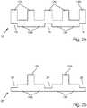
- Fig. 2ashows a schematic cross-sectional view of the first ferromagnetic bar 10.
- Fig. 2bshows a schematic cross-sectional view of the second ferromagnetic bar 20. It is noted that both fig. 2a and fig. 2b depict only parts of a respective ferromagnetic bar 10, 20, wherein the ferromagnetic bars 10, 20 as shown in fig. 1 are considerably longer.
- the first ferromagnetic bar 10 as shown in fig. 2ahas ferromagnetic cores 125 extending upward, wherein the cores 125 have a certain distance that is equal between each two pairs of cores 125. Between each two cores 125, there is arranged a magnetic coupling element 126.
- each second core 125there is formed a recess 15.
- the recesses 15are arranged at the lower side of the first ferromagnetic bar 10.
- the second ferromagnetic bar 20also has ferromagnetic cores 125, which are, however, arranged with twice the distance of the ferromagnetic cores 125 of the first ferromagnetic bar 10 as shown in fig. 2a .
- the second ferromagnetic bar 20has recesses 25 formed at its upper side at each second position where the first ferromagnetic bar 10 has a core 125.
- the recesses 25 of the second ferromagnetic bar 20interact with corresponding recesses 15 of the first ferromagnetic bars 10 such that the first ferromagnetic bars 10 and the second ferromagnetic bars 20 are arranged as shown in fig. 1 .
- first ferromagnetic bars 10are arranged parallel to each other, that a plurality of second ferromagnetic bars 20 are arranged parallel to each other, and that the first ferromagnetic bars 10 are arranged perpendicular to the second ferromagnetic bars 20.
- the recesses 15, 25allow for a simple assembly of the configuration as shown in fig. 1 .
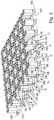
- Fig. 3shows a part of a module for a laboratory sample distribution system according to a second embodiment. This configuration is similar to the configuration according to the first embodiment as shown in fig. 1 . For that reason, only the differences will be discussed in the following. Regarding the other items and features, reference is made to the description of fig. 1 given above.
- the ferromagnetic bars 10, 20each comprise a magnetic coupling protrusion 128 between a ferromagnetic core 125 and an outer edge 160, 170, 180, 190 (as depicted by the dashed line) of the module as magnetic coupling enhancement means.
- the outer edges 160, 170, 180, 190 of a moduleare the edges determining a border line to another module.
- the outer edges 160, 170, 180, 190are determined by border lines of the transport plane (not shown) of a respective module.
- the magnetic coupling protrusions 128are arranged in line with the magnetic coupling elements 126 between the cores 125.
- the magnetic coupling protrusions 128provide for an increased coupling to ferromagnetic cores 125 of neighboring modules.
- Each magnetic coupling protrusion 128comprises a magnetic coupling surface 129 positioned at the outer edge (160, 170, 180, 190) of the module and facing towards a surrounding of the module.
- the magnetic coupling surface 129can especially face to another magnetic coupling surface of a neighboring module such that a distance between the magnetic coupling surfaces 129 is minimized. Thus, a gap between the magnetic coupling surfaces 129 is minimized. Magnetic coupling between neighboring modules is thus enhanced.
- magnetic couplingcan be enhanced without a need for additional magnetic coupling rods.
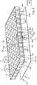
- Fig. 4shows a module 105 for a laboratory sample distribution system, the module 105 comprising a transport plane 110 that is adapted such that sample container carriers can move on it. Furthermore, a number of magnetic sensors 130 are distributed in the transport plane 110. These magnetic sensors 130 can be used in order to sense respective positions of sample container carriers.
- a number of electro-magnetic actuators 120 with respective ferromagnetic cores 125are arranged. Between the ferromagnetic cores 125, respective magnetic coupling elements 126 are arranged.
- the bars 10, 20are a supported by a supporting structure 250 of the module 105.
- the module 105is retained with a lower or bottom side of the supporting structure 250 on pillars 310 of a retaining frame 300 of a laboratory sample distribution system.
- the bottom side of the supporting structureis opposite to the transport plane 110.
- Fig. 5shows a laboratory automation system 5 comprising a first laboratory station 6, a second laboratory station 7 and a laboratory sample distribution system 100.
- the laboratory stations 6, 7are shown as examples for a plurality of laboratory stations that are typically present in a laboratory automation system. They can, for example, be pre-analytical, analytical and/or post-analytical stations that are adapted to perform tasks like analyzing a sample, centrifugation of a sample or the like.
- the laboratory sample distribution system 100comprises a first module 105 and a second module 105a.
- An outer edge 190 of the first module 105touches an outer edge 170a of the second module.
- the first module 105 and the second module 105aare concatenated such that they form a common transport plane.
- the common transport planeis formed by the transport plane 110 of the first module 105 and the transport plane 110a of the second module 105a.
- the first module 105 and the second module 105aare retained with bottom sides of their supporting structures 250, 250a on pillars 310 of a retaining frame 300 of the laboratory sample distribution system 100.
- magnetic coupling rods 30are positioned between respective ferromagnetic bars 20, 20a of different modules 105, 105a.
- the magnetic coupling rods 30, each having a rectangular cross-section area,are formed out of magnetically highly permeable material in order to provide for an effective coupling.
- Each magnetic coupling rod 30abuts two magnetic coupling surfaces 127, 127a of the different modules 105, 105a. Thus, there is no remaining gap between neighboring magnetic rods 20, 20a.
- the arrangementis shown in further detail in fig. 6 , which depicts the encircled part VI of fig. 5 .
- This measureleads to a magnetic coupling between cores 125, 125a of different modules 105, 105a that is approximately the same as the magnetic coupling between neighboring cores 125 of a module 105 that are connected by means of a magnetic coupling element 126.
- the magnetic coupling rods 30are detachably fixed by a number of springs 200 on pillars 310 from the retaining frame 300 to the contact surfaces 127, 127a. This allows for a simple detaching and attaching of the magnetic coupling rods 30 in the case if one of the modules 105, 105a should be replaced.
- a typical laboratory sample distribution system 100comprises more than two modules 105, 105a. Magnetic coupling between a plurality of modules 105, 105a can be enhanced just like described here with respect to two modules 105, 105a.
- the laboratory sample distribution system 100further comprises a sample container carrier 140, wherein the sample container carrier 140 carries a sample container 145.
- the sample container carrier 140has a magnetically active device in the form of a permanent magnet that is not shown in fig. 5 .
- the sample container carrier 140is adapted to move on the common transport plane.
- the sample container 145is embodied as a tube made of transparent plastic material with an opening at its top side and is adapted to carry blood samples or other medical samples. By means of the sample container carrier 140, sample containers 145 can be distributed between the laboratory stations 6, 7 and other equipment.
- a typical laboratory sample distribution system 100comprises more than one sample container carrier 140.
- the sample container carrier 140 shown in fig. 5is given as an exemplary illustration only.
- the laboratory sample distribution system 100further comprises a control unit 150 that is adapted to drive the electro-magnetic actuators 120, 120a such that the sample container carriers 140 move over the common transport plane on respective transport paths.
- Fig. 7shows in detail a part of a laboratory automation system comprising a laboratory sample distribution system with two modules 105, 105a, wherein the kind of module 105, 105a is shown in part in fig. 3 .
- the further details of the modules 105, 105areference is made to fig. 3 and the corresponding description given above.
- the configuration of fig. 7is similar to the configuration according to the first embodiment as shown in fig. 6 . For that reason, only the differences will be discussed in the following.
- the ferromagnetic bars 20, 20aeach comprise a magnetic coupling protrusion 128, 128a.
- Each magnetic coupling protrusion 128, 128acomprises a magnetic coupling surface 129, 129a and facing towards the other such that a distance between the magnetic coupling surfaces 129 is minimized.
- a gap between the magnetic coupling surfaces 129is minimized. Magnetic coupling between neighboring 105, 105a modules is thus enhanced.
- each magnetic coupling surfacemay have a cross-section area being larger than a cross-section area of the magnetic coupling elements 126.
Landscapes
- General Health & Medical Sciences (AREA)
- Health & Medical Sciences (AREA)
- Life Sciences & Earth Sciences (AREA)
- Chemical & Material Sciences (AREA)
- Analytical Chemistry (AREA)
- Biochemistry (AREA)
- Physics & Mathematics (AREA)
- General Physics & Mathematics (AREA)
- Immunology (AREA)
- Pathology (AREA)
- Automatic Analysis And Handling Materials Therefor (AREA)
- Non-Mechanical Conveyors (AREA)
- Sampling And Sample Adjustment (AREA)
Description
- The invention relates to a module for a laboratory sample distribution system, to a laboratory sample distribution system comprising such a module, and to a laboratory automation system comprising such a laboratory sample distribution system.
- Known laboratory sample distribution systems are typically used in laboratory automation systems in order to distribute or to transport samples contained in sample containers between different laboratory stations.
- A typical laboratory sample distribution system is shown in document
WO 2013/064656 A1 . Such a laboratory sample distribution system provides for a high throughput and for reliable operation. - It has been found out that such a laboratory sample distribution system can be assembled out of a plurality of modules, wherein the modules can be put together in order to arrive at a desired shape and size of a transport plane of the resulting laboratory sample distribution system.
- It is an object of the invention to provide for a module for a laboratory sample distribution system that is improved regarding magnetic coupling between such modules. It is a further object of the present invention to provide for a laboratory sample distribution system comprising such modules, and it is another object of the present invention to provide for a laboratory automation system comprising such a laboratory sample distribution system.
- This is achieved by a module according to claim 1, a laboratory sample distribution system according to
claim 6 or claim 7 and a laboratory automation system according toclaim 10. - The invention relates to a module for a laboratory sample distribution system. The module comprises a transport plane that is adapted to support sample container carriers. Each sample container carrier comprises at least one magnetically active device. It should be noted that the transport plane could also be denoted as a transport surface. It should further be noted that it could also be said that the transport plane or transport surface carries the sample container carriers.
- The module further comprises a number of electro-magnetic actuators, being stationary arranged below the transport plane. The electro-magnetic actuators are adapted to move sample container carriers on top of the transport plane by applying a magnetic force to the sample container carriers. Each electro-magnetic actuator comprises a ferromagnetic core, wherein adjacent ferromagnetic cores are magnetically coupled to each other by respective magnetic coupling elements.
- The magnetic coupling elements are embodied as bars made of magnetic, especially ferromagnetic, material. The magnetic coupling elements increase magnetic coupling between the ferromagnetic cores and thus increase magnetic field strengths that are used in order to drive the sample container carriers. Thus, the magnetic coupling elements increase energy efficiency of the module.
- The module further comprises magnetic coupling enhancement means for increasing magnetic coupling to and between ferromagnetic cores of adjacent modules. The magnetic coupling enhancement means can be implemented as follows.
- The magnetic coupling enhancement means comprise a number of magnetic coupling protrusions, each magnetic coupling protrusion being positioned between an outer edge of the module and a corresponding ferromagnetic core of an electro-magnetic actuator being positioned adjacent to the outer edge. The outer edge of a module is an edge determining a border line to another module. Typically, the outer edge is determined by a border line of the transport plane of a respective module. Typically, the module has four outer edges forming a rectangular shape. Such a magnetic coupling protrusion increases magnetic coupling to a neighboring module, because it typically faces towards the neighboring module. Magnetic coupling is increased, when the neighboring module has a corresponding protrusion such that a distance between the two protrusions is minimized.
- The magnetic coupling enhancement means comprise a number of contact surfaces located at ferromagnetic cores of electro-magnetic actuators being positioned adjacent to the outer edge of the module, or located at respective magnetic coupling elements of the electro-magnetic actuators being positioned adjacent to the outer edge of the module, or located at respective magnetic coupling protrusions. The contact surfaces are adapted to be contacted by a corresponding number of magnetic coupling rods. This embodiment allows for providing increased magnetic coupling by placing magnetic rods between the contact surfaces. By means of such an embodiment, it is possible to couple ferromagnetic cores located adjacent to outer edges of neighboring modules without a gap. In this case, the number of rods equals the number of contact surfaces per module. Alternatively, it is possible, that a single rod extends along the outer edge of the module and thereby contacts several contact surfaces.
- Each magnetic coupling protrusion comprises a magnetic coupling surface positioned at the outer edge of the module and facing towards a surrounding of the module, wherein the magnetic coupling surfaces are arranged to magnetically couple to a further magnetic coupling surface of a neighboring module. In other words, when two modules are put together, two magnetic coupling surfaces are positioned adjacent to each other and face each other so that a gap between the surfaces is minimized. This can be achieved by arrangement of the magnetic coupling protrusions perpendicular to an outer edge of the module, and by arrangement of the magnetic coupling surface parallel to the outer edge. This leads to a specifically high magnetic coupling.
- According to an embodiment, each magnetic coupling surface has a cross-section area being larger than a cross-section area of the magnetic coupling elements. Especially, the magnetic coupling surfaces have at least twice the cross-section area of the magnetic coupling elements. Increasing of the cross-section area of the magnetic coupling surfaces can increase magnetic coupling between ferromagnetic cores of different modules. Increasing the magnetic coupling surface relative to the cross-section area of the magnetic coupling elements takes into account that magnetic coupling between ferromagnetic cores of different modules is typically decreased by a gap between the magnetic coupling surfaces. Increasing the area of the magnetic coupling surface compensates this effect at least partially.
- A number of positions is defined on the module in a chequered manner. Each electro-magnetic actuator is located on one such position such that in each second line of positions each second position is left blank. This arrangement of electro-magnetic actuators has been proven suitable for typical applications of the laboratory sample distribution system. For example, lines in which an electro-magnetic actuator is present at each position can be used as paths on which sample container carriers can move. Neighboring lines with less electro-magnetic actuators provide for a certain distance between the paths.
- The module has four outer edges forming a rectangular shape. Electro-magnetic actuators are located on each position along two of the four edges that are located perpendicular to each other. Furthermore, electro-magnetic actuators are located on each second position along two further edges of the four edges. This embodiment allows for a theoretically unlimited concatenation of modules to form a laboratory sample distribution system. If the modules are concatenated such that a line adjacent to an outer edge having an electro-magnetic actuator at each position adjoins a line on an adjacent module having an electro-magnetic actuator at each second position, the pattern of electro-magnetic actuators formed over the whole common transport plane extending over all modules is not disturbed by a border between two modules.
- The ferromagnetic cores, the magnetic coupling elements between those ferromagnetic cores, and the magnetic coupling enhancement means of each line or some lines of positions having no blanks are formed as a single ferromagnetic bar. This can significantly simplify assembly of such a module.
- The module comprises a first set of ferromagnetic bars and a second set of ferromagnetic bars. The ferromagnetic bars of the first set are arranged parallel to each other and the ferromagnetic bars of the second set are arranged parallel to each other. The ferromagnetic bars of the first set are perpendicular to the ferromagnetic bars of the second set. When the bars are placed appropriately during assembly of the module, the ferromagnetic cores, the magnetic coupling elements and the magnetic coupling enhancement means are formed by means of the bars.
- According to an embodiment, the ferromagnetic bars each have recesses arranged such that the recesses of the ferromagnetic bars of the first set are complementary to the recesses of the ferromagnetic bars of the second set. The ferromagnetic bars are arranged such that corresponding complementary recesses abut each other. This allows for a specific simplification in assembly of the module. Typically, one bar of two bars abutting each other at a recess has a ferromagnetic core extending upwards.
- According to an embodiment, the ferromagnetic bars are each formed out of a transformer sheet or out of a group of parallel transformer sheets being electrically isolated to each other. Such a configuration has been proven useful for typical applications. Especially, a cheap and magnetically suitable material can be used. Using a plurality of transformer sheets being electrically isolated to each other can in particular minimize eddy currents in the sheets. Thus, a parasitic resistance and corresponding heat generation can be minimized.
- According to an embodiment, the magnetic coupling protrusions are formed out of iron sheets. They can also be formed out of transformer sheets. This has been proven suitable for typical applications.
- According to an embodiment, the ferromagnetic cores, the magnetic coupling elements, the magnetic coupling enhancement means, the ferromagnetic bars and/or the transformer sheets are formed out of magnetically high permeable material. This has been proven useful for typical applications because coupling of magnetic fields is significantly enhanced. This increases energy efficiency of the modules and hence energy efficiency of the laboratory sample distribution system.
- The invention relates further to a laboratory sample distribution system. The laboratory sample distribution system can be implemented as follows.
- The laboratory sample distribution system may comprise a number of sample container carriers, being adapted to carry one or more sample containers. Each sample container carrier comprises at least one magnetically active device.
- The laboratory sample distribution system comprises a number of modules according to the invention as described above. It should be noted that all variations and embodiments as discussed above can be used in the laboratory sample distribution system, as long as magnetic coupling protrusions are present. Discussed advantages apply accordingly.
- The modules are arranged adjacent to each other such that magnetic coupling protrusions of neighboring modules face each other and that the transport planes of the modules form a common transport plane being adapted to support the sample container carriers. This allows for an easy and efficient scaling of the laboratory sample distribution system by using an appropriate number of modules arranged in a specific way in order to resemble an intended shape of the common transport plane.
- The laboratory sample distribution system further comprises a control device, being configured to control the movement of the sample container carriers on top of the common transport plane by driving the electro-magnetic actuators of the modules such that the sample container carriers move along corresponding transport paths. This allows for a central controlling of the sample container carriers such that they execute certain transport tasks, for example to distribute or to transport sample containers containing blood samples or other medical samples to and from laboratory stations.
- The control device can be adapted to control movement of the sample container carriers on the common transport plane in two dimensions. This allows for a higher flexibility.
- By means of the laboratory sample distribution system just described, energy efficiency of the laboratory sample distribution system comprising several modules can be significantly increased because magnetic coupling between neighboring modules is increased as described above with reference to the modules.
- In the following, a second way to implement the laboratory sample distribution system is described. It bases on modules having contact surfaces.
- The laboratory sample distribution system comprises a number of magnetic coupling rods being positioned and fixed between two neighboring contact surfaces of respective different modules. This increases magnetic coupling between neighboring modules in order to increase energy efficiency of the laboratory sample distribution system. Typically, the number of rods equals the number of contact surfaces per module. Alternatively, it is possible, that a single rod extends along the outer edge of the module and thereby contacts several contact surfaces.
- The rods provide for an increased coupling between respective neighboring modules. The rods can even be exchanged one by one and they can be retrofitted in an already existing laboratory sample distribution system in order to increase energy efficiency.
- According to an embodiment, the laboratory sample distribution system comprises a retaining frame, wherein the retaining frame retains the number of modules from a bottom side of the modules. The bottom side of the modules is opposite to the common transport plane. The number of magnetic coupling rods is detachably fixed by a number of springs, especially coil springs, extending from the retaining frame to the rods. The contact surfaces may be located at bottom sides of ferromagnetic cores of electro-magnetic actuators being positioned adjacent to the outer edge of the module, or located at bottom sides of respective magnetic coupling elements of the electro-magnetic actuators being positioned adjacent to the outer edge the module or located at bottom sides of respective magnetic coupling protrusions. This allows for a simple detaching and attaching of the magnetic coupling rods in the case if one of the modules should be replaced.
- According to an embodiment, each magnetic coupling rod has a rectangular cross-section. The contact surfaces may be parallel to the common transport plane and located at bottom sides as mentioned above. Then the rods can be easily provided from the bottom to the contact surfaces.
- The invention further relates to a laboratory automation system, comprising a number of pre-analytical, analytical and/or post-analytical (laboratory) stations, and a laboratory sample distribution system as described above adapted to distribute or to transport the sample container carriers and/or sample containers between the stations. The stations may be arranged adjacent to the laboratory sample distribution system.
- Pre-analytical stations may be adapted to perform any kind of pre-processing of samples, sample containers and/or sample container carriers.
- Analytical stations may be adapted to use a sample or part of the sample and a reagent to generate a measuring signal, the measuring signal indicating if and in which concentration, if any, an analyte exists.
- Post-analytical stations may be adapted to perform any kind of post-processing of samples, sample containers and/or sample container carriers.
- The pre-analytical, analytical and/or post-analytical stations may comprise at least one of a decapping station, a recapping station, an aliquot station, a centrifugation station, an archiving station, a pipetting station, a sorting station, a tube type identification station, a sample quality determining station, an add-on buffer station, a liquid level detection station, and a sealing/desealing station.
- The invention will be described in detail with respect to the drawings schematically depicting embodiments of the invention. In detail:
- Fig. 1
- shows a part of a module for a laboratory sample distribution system according to a first embodiment,
- Fig. 2a
- shows a ferromagnetic bar used in the configuration shown in
fig. 1 , - Fig. 2b
- shows another ferromagnetic bar used in the configuration of
fig. 1 , - Fig. 3
- shows a part of a module for a laboratory sample distribution system according to a second embodiment,
- Fig. 4
- shows a module for a laboratory sample distribution system using the configuration of
fig. 1 , - Fig. 5
- shows a laboratory automation system comprising a laboratory sample distribution system with two modules as shown in
fig. 4 , - Fig. 6
- shows a part of the laboratory automation system as shown in
fig. 5 in more detail, and - Fig. 7
- shows a part of a laboratory automation system comprising a laboratory sample distribution system with two modules as one of them shown in part in
fig. 3 . Fig. 1 shows a part of a module for a laboratory sample distribution system according to a first embodiment. It should be noted that typical parts of such a module such as a transport plane or a supporting structure are not shown infig. 1 .- A plurality of electro-
magnetic actuators 120 that comprise electro-magnetic coils are arranged in a configuration such that a field of positions is defined in a chequered manner, wherein in each second line of positions each second position is left blank. - Each electro-
magnetic actuator 120 comprises aferromagnetic core 125. Theferromagnetic core 125 increases a magnetic field generated by a respective electro-magnetic coil of the electro-magnetic actuator 120. - Between
ferromagnetic cores 125 of neighboring electro-magnetic actuators 120, a respectivemagnetic coupling element 126 is arranged. Themagnetic coupling elements 126 increase magnetic coupling between respective pairs offerromagnetic cores 125. - The electro-
magnetic actuators 120 are adapted to drive sample container carriers on a transport plane (not shown) that is typically positioned above the electro-magnetic actuators 120. By means of themagnetic coupling elements 126, energy efficiency of the module can be enhanced because therespective cores 125 of neighboring electro-magnetic actuators 120 are magnetically coupled. - The
ferromagnetic cores 125 and themagnetic coupling elements 126 that are arranged along a line extending from the front side to the rear side as shown infig. 1 are embodied as respective first ferromagnetic bars 10. Correspondingly, theferromagnetic cores 125 and themagnetic coupling elements 126 arranged in lines perpendicular to that direction, i.e. from the left to the right side infig. 1 , with the exception offerromagnetic cores 125 already belonging to the firstferromagnetic bars 10, are embodied as respective second ferromagnetic bars 20. - The
ferromagnetic bars - The embodiment of the
ferromagnetic cores 125 and themagnetic coupling elements 126 as respectiveferromagnetic bars cores 125 andmagnetic coupling elements 126 within one module. - If the parts of a module as shown in
fig. 1 are concatenated with identical parts of another module, there will remain respective gaps betweencores 125 of neighboring modules. For that reason, theferromagnetic bars contact surface 127 as magnetic coupling enhancement means. The contact surfaces 127 are positioned at the respective lower or bottom sides of theferromagnetic bars fig. 5 how this can be accomplished. Fig. 2a shows a schematic cross-sectional view of the firstferromagnetic bar 10.Fig. 2b shows a schematic cross-sectional view of the secondferromagnetic bar 20. It is noted that bothfig. 2a and fig. 2b depict only parts of a respectiveferromagnetic bar ferromagnetic bars fig. 1 are considerably longer.- The first
ferromagnetic bar 10 as shown infig. 2a hasferromagnetic cores 125 extending upward, wherein thecores 125 have a certain distance that is equal between each two pairs ofcores 125. Between each twocores 125, there is arranged amagnetic coupling element 126. - Below each
second core 125, there is formed arecess 15. Therecesses 15 are arranged at the lower side of the firstferromagnetic bar 10. - The second
ferromagnetic bar 20 also hasferromagnetic cores 125, which are, however, arranged with twice the distance of theferromagnetic cores 125 of the firstferromagnetic bar 10 as shown infig. 2a . Instead, the secondferromagnetic bar 20 hasrecesses 25 formed at its upper side at each second position where the firstferromagnetic bar 10 has acore 125. Therecesses 25 of the secondferromagnetic bar 20 interact withcorresponding recesses 15 of the firstferromagnetic bars 10 such that the firstferromagnetic bars 10 and the secondferromagnetic bars 20 are arranged as shown infig. 1 . In particular, they can be arranged such that a plurality of firstferromagnetic bars 10 are arranged parallel to each other, that a plurality of secondferromagnetic bars 20 are arranged parallel to each other, and that the firstferromagnetic bars 10 are arranged perpendicular to the second ferromagnetic bars 20. - The
recesses fig. 1 . Fig. 3 shows a part of a module for a laboratory sample distribution system according to a second embodiment. This configuration is similar to the configuration according to the first embodiment as shown infig. 1 . For that reason, only the differences will be discussed in the following. Regarding the other items and features, reference is made to the description offig. 1 given above.- In contrast to
fig. 1 , theferromagnetic bars magnetic coupling protrusion 128 between aferromagnetic core 125 and anouter edge outer edges outer edges magnetic coupling protrusions 128 are arranged in line with themagnetic coupling elements 126 between thecores 125. Themagnetic coupling protrusions 128 provide for an increased coupling toferromagnetic cores 125 of neighboring modules. - Each
magnetic coupling protrusion 128 comprises amagnetic coupling surface 129 positioned at the outer edge (160, 170, 180, 190) of the module and facing towards a surrounding of the module. Themagnetic coupling surface 129 can especially face to another magnetic coupling surface of a neighboring module such that a distance between the magnetic coupling surfaces 129 is minimized. Thus, a gap between the magnetic coupling surfaces 129 is minimized. Magnetic coupling between neighboring modules is thus enhanced. - By means of the second embodiment shown in
fig. 3 , magnetic coupling can be enhanced without a need for additional magnetic coupling rods. Fig. 4 shows amodule 105 for a laboratory sample distribution system, themodule 105 comprising atransport plane 110 that is adapted such that sample container carriers can move on it. Furthermore, a number ofmagnetic sensors 130 are distributed in thetransport plane 110. Thesemagnetic sensors 130 can be used in order to sense respective positions of sample container carriers.- Below the
transport plane 110, parts as shown infig. 1 are arranged. Specifically, a number of electro-magnetic actuators 120 with respectiveferromagnetic cores 125 are arranged. Between theferromagnetic cores 125, respectivemagnetic coupling elements 126 are arranged. Thebars structure 250 of themodule 105. Themodule 105 is retained with a lower or bottom side of the supportingstructure 250 onpillars 310 of a retainingframe 300 of a laboratory sample distribution system. The bottom side of the supporting structure is opposite to thetransport plane 110. Fig. 5 shows alaboratory automation system 5 comprising afirst laboratory station 6, asecond laboratory station 7 and a laboratorysample distribution system 100. Thelaboratory stations - The laboratory
sample distribution system 100 comprises afirst module 105 and asecond module 105a. Anouter edge 190 of thefirst module 105 touches anouter edge 170a of the second module. Thefirst module 105 and thesecond module 105a are concatenated such that they form a common transport plane. The common transport plane is formed by thetransport plane 110 of thefirst module 105 and thetransport plane 110a of thesecond module 105a. Thefirst module 105 and thesecond module 105a are retained with bottom sides of their supportingstructures pillars 310 of a retainingframe 300 of the laboratorysample distribution system 100. - Regarding the further details of the
modules fig. 4 and the corresponding description given above. - In order to enhance coupling between
ferromagnetic cores 125, 125a ofdifferent modules magnetic coupling rods 30 are positioned between respectiveferromagnetic bars different modules magnetic coupling rods 30, each having a rectangular cross-section area, are formed out of magnetically highly permeable material in order to provide for an effective coupling. Eachmagnetic coupling rod 30 abuts two magnetic coupling surfaces 127, 127a of thedifferent modules magnetic rods fig. 6 , which depicts the encircled part VI offig. 5 . - This measure leads to a magnetic coupling between
cores 125, 125a ofdifferent modules cores 125 of amodule 105 that are connected by means of amagnetic coupling element 126. - The
magnetic coupling rods 30 are detachably fixed by a number ofsprings 200 onpillars 310 from the retainingframe 300 to the contact surfaces 127, 127a. This allows for a simple detaching and attaching of themagnetic coupling rods 30 in the case if one of themodules - It is to be understood that a typical laboratory
sample distribution system 100 comprises more than twomodules modules modules - The laboratory
sample distribution system 100 further comprises asample container carrier 140, wherein thesample container carrier 140 carries asample container 145. Thesample container carrier 140 has a magnetically active device in the form of a permanent magnet that is not shown infig. 5 . Thesample container carrier 140 is adapted to move on the common transport plane. Thesample container 145 is embodied as a tube made of transparent plastic material with an opening at its top side and is adapted to carry blood samples or other medical samples. By means of thesample container carrier 140,sample containers 145 can be distributed between thelaboratory stations - It should be noted that a typical laboratory
sample distribution system 100 comprises more than onesample container carrier 140. Thesample container carrier 140 shown infig. 5 is given as an exemplary illustration only. - The laboratory
sample distribution system 100 further comprises acontrol unit 150 that is adapted to drive the electro-magnetic actuators sample container carriers 140 move over the common transport plane on respective transport paths. Fig. 7 shows in detail a part of a laboratory automation system comprising a laboratory sample distribution system with twomodules module fig. 3 . Regarding the further details of themodules fig. 3 and the corresponding description given above. The configuration offig. 7 is similar to the configuration according to the first embodiment as shown infig. 6 . For that reason, only the differences will be discussed in the following. Regarding the other items and features, reference is made to the description offig. 6 given above.- In contrast to
fig. 6 , theferromagnetic bars magnetic coupling protrusion magnetic coupling protrusion magnetic coupling surface - By means of the second embodiment shown in
fig. 7 , magnetic coupling can be enhanced without a need for additional magnetic coupling rods. However, additionally, magnetic coupling rods can be provided as shown infigs. 5 and6 and described above. Additionally, each magnetic coupling surface may have a cross-section area being larger than a cross-section area of themagnetic coupling elements 126.
Claims (10)
- Module (105, 105a) for a laboratory sample distribution system (100), comprising:- a transport plane (110, 110a) having a rectangular border determining the outer edges (160, 170, 180, 190, 170a) of the module (105, 105a), the transport plane (110, 110a) being adapted to support sample container carriers (140), each sample container carrier (140) comprising at least one magnetically active device;- a number of electro-magnetic actuators (120, 120a) being stationary arranged below the transport plane (110, 110a) in a configuration such that a field of positions in a plane parallel to the transport plane (110, 110a) is defined in a chequered manner, wherein in each second line of positions each second position is left blank, the electro-magnetic actuators 120, 120a) being adapted to move the sample container carriers (140) an top of the transport plane (110, 110a) by applying a magnetic force to the sample container carriers (140), wherein each electromagnetic actuator (120, 120a) comprises a ferromagnetic core (125), wherein adjacent ferromagnetic cores (125) are magnetically coupled to each other by respective magnetic coupling elements (126),- wherein the ferromagnetic cores (125) and the magnetic coupling elements (126) that are arranged along a line extending from the front side to the rear side of the transport plane (110, 110a) are forming respective first ferromagnetic bars (10), and- wherein the ferromagnetic cores (125) and the magnetic coupling elements (126) that are arranged in lines from the left to the right side of the transport plane (110, 110a), with the exception of ferromagnetic cores (125) already belonging to the first ferromagnetic bars (10), are forming respective second ferromagnetic bars (20); and- magnetic coupling enhancement means for increasing magnetic coupling of the module (105, 105a) to an adjacent module (105, 105a), the magnetic coupling enhancement means being formed as:- a number of magnetic coupling protrusions (128, 128a), each magnetic coupling protrusion (128, 128a) being positioned between an outer edge (160, 170, 180, 190, 170a) of the module (105, 105a) and a ferromagnetic core (125) of an electromagnetic actuator (120, 120a) being positioned adjacent to the outer edge (160, 170, 180, 190, 170a),- wherein each magnetic coupling protrusion (128, 128a) comprises a magnetic coupling surface (129, 129a) positioned at the outer edge (160, 170, 180, 190, 170a) of the module (105, 105a), the magnetic coupling surface (129, 129a) facing towards the surroundings of the module (105, 105a) and being arranged to magnetically couple to a further magnetic coupling surface (129, 129a) of an adjacent module (105, 105a), and- wherein each of the first ferromagnetic bars (10) and each of the second ferromagnetic bars (20) comprises a magnetic coupling protrusion (128, 128a),
or- a number of contact surfaces (127, 127a), the contact surfaces (127, 127a) being adapted to be contacted by a corresponding number of magnetic coupling rods (30), and- wherein each of the first ferromagnetic bars (10) and each of the second ferromagnetic bars (20) comprises a contact surface (127, 127a). - Module (105, 105a) according to claim 1,characterized in that- each magnetic coupling surface (129, 129a) has a cross-section area being larger than a cross-section area of the magnetic coupling elements (126).
- Module (105, 105a) according to claim 1 or 2,characterized in that- the ferromagnetic bars (10, 20, 20a) each have recesses (15, 25) arranged such that the recesses (15) of the ferromagnetic bars (10) of the first set are complementary to the recesses (25) of the ferromagnetic bars (20, 20a) of the second set,- wherein the ferromagnetic bars (10, 20, 20a) are arranged such that corresponding complementary recesses (15, 25) abut each other.
- Module (105, 105a) according one of the preceding claims,characterized in that- the ferromagnetic bars (10, 20, 20a) are each formed out of a transformer sheet or out of a group of parallel transformer sheets being electrically isolated to each other.
- Module (105, 105a) according to one of the preceding claims,characterized in that- the ferromagnetic cores (125), the magnetic coupling elements (126), the magnetic coupling enhancement means (127, 127a, 128, 128a), the ferromagnetic bars (10, 20, 20a) and/or the transformer sheets are formed out of magnetically high permeable material.
- Laboratory sample distribution system (100), comprising:- a number of sample container carriers (140), being adapted to carry one or more sample containers (145), each sample container carrier (140) comprising at least one magnetically active device,- a number of modules (105, 105a) according to one of the preceding claims, wherein the modules (105, 105a) are arranged adjacent to each other such that magnetic coupling protrusions (128, 128a) of neighbouring modules (105, 105a) face each other and that the transport planes (110, 110a) of the modules (105, 105a) form a common transport plane being adapted to support the sample container carriers (140), and- a control device (150), being configured to control the movement of the sample container carriers (140) on top of the common transport plane by driving the electro-magnetic actuators (120, 120a) of the modules (105, 105a) such that the sample container carriers (140) move along corresponding transport paths.
- Laboratory sample distribution system (100), comprising:- a number of sample container carriers (140), being adapted to carry one or more sample containers (145), each sample container carrier (140) comprising at least one magnetically active device,- a number of modules (105, 105a) according to one of the preceding claims, wherein the modules (105, 105a) are arranged adjacent to each other such that the transport planes (110, 110a) of the modules (105, 105a) form a common transport plane being adapted to support the sample container carriers (140),- a number of magnetic coupling rods (30) being positioned and fixed between two neighbouring contact surfaces (127, 127a) of respective different modules (105, 105a), and- a control device (150), being configured to control the movement of the sample container carriers (140) on top of the common transport plane by driving the electro-magnetic actuators (120, 120a) of the modules (105, 105a) such that the sample container carriers (140) move along corresponding transport paths.
- Laboratory sample distribution system (100) according to claim 7,characterized in that- the laboratory sample distribution system (100) comprises a retaining frame (300), wherein the retaining frame (300) retains the number of modules (105, 105a) from a bottom side of the modules (105, 105a),- wherein the number of magnetic coupling rods (30) is detachably fixed to the contact surfaces (127, 127a) by means of a number of springs (200), extending from the retaining frame (300) to respective magnetic coupling rods (30), such that a spring force is applied to the respective magnetic coupling rods (30).
- Laboratory sample distribution system (100) according to claim 7 or 8,characterized in that- each magnetic coupling rod (30) has a rectangular cross-section.
- Laboratory automation system (5), comprising:- a number of laboratory stations (6, 7), preferably pre-analytical, analytical and/or post-analytical stations, and- a laboratory sample distribution system (100) according to anyone of claims 6 to 9 adapted to distribute sample containers (145) and/or sample container carriers (140) between the stations (6, 7).
Priority Applications (4)
| Application Number | Priority Date | Filing Date | Title |
|---|---|---|---|
| EP14187891.8AEP3006943B1 (en) | 2014-10-07 | 2014-10-07 | Module for a laboratory sample distribution system, laboratory sample distribution system and laboratory automation system |
| US14/865,822US9618525B2 (en) | 2014-10-07 | 2015-09-25 | Module for a laboratory sample distribution system, laboratory sample distribution system and laboratory automation system |
| JP2015198309AJP6080927B2 (en) | 2014-10-07 | 2015-10-06 | Module for laboratory sample dispensing system, laboratory sample dispensing system, and laboratory automation system |
| CN201511028063.9ACN105600468B (en) | 2014-10-07 | 2015-10-08 | Module, sample dispensing system and the automated system of sample dispensing system |
Applications Claiming Priority (1)
| Application Number | Priority Date | Filing Date | Title |
|---|---|---|---|
| EP14187891.8AEP3006943B1 (en) | 2014-10-07 | 2014-10-07 | Module for a laboratory sample distribution system, laboratory sample distribution system and laboratory automation system |
Publications (2)
| Publication Number | Publication Date |
|---|---|
| EP3006943A1 EP3006943A1 (en) | 2016-04-13 |
| EP3006943B1true EP3006943B1 (en) | 2020-04-22 |
Family
ID=51659579
Family Applications (1)
| Application Number | Title | Priority Date | Filing Date |
|---|---|---|---|
| EP14187891.8AActiveEP3006943B1 (en) | 2014-10-07 | 2014-10-07 | Module for a laboratory sample distribution system, laboratory sample distribution system and laboratory automation system |
Country Status (4)
| Country | Link |
|---|---|
| US (1) | US9618525B2 (en) |
| EP (1) | EP3006943B1 (en) |
| JP (1) | JP6080927B2 (en) |
| CN (1) | CN105600468B (en) |
Families Citing this family (68)
| Publication number | Priority date | Publication date | Assignee | Title |
|---|---|---|---|---|
| DE102010028769A1 (en) | 2010-05-07 | 2011-11-10 | Pvt Probenverteiltechnik Gmbh | System for transporting containers between different stations and container carriers |
| EP2589966A1 (en) | 2011-11-04 | 2013-05-08 | Roche Diagnostics GmbH | Laboratory sample distribution system and corresponding method of operation |
| EP2589967A1 (en) | 2011-11-04 | 2013-05-08 | Roche Diagnostics GmbH | Laboratory sample distribution system and corresponding method of operation |
| EP2589968A1 (en) | 2011-11-04 | 2013-05-08 | Roche Diagnostics GmbH | Laboratory sample distribution system, laboratory system and method of operating |
| DE102014202843B3 (en) | 2014-02-17 | 2014-11-06 | Roche Pvt Gmbh | Transport device, sample distribution system and laboratory automation system |
| DE102014202838B3 (en) | 2014-02-17 | 2014-11-06 | Roche Pvt Gmbh | Transport device, sample distribution system and laboratory automation system |
| EP2927167B1 (en) | 2014-03-31 | 2018-04-18 | F. Hoffmann-La Roche AG | Dispatch device, sample distribution system and laboratory automation system |
| EP2927163B1 (en) | 2014-03-31 | 2018-02-28 | Roche Diagnostics GmbH | Vertical conveyor, sample distribution system and laboratory automation system |
| EP2927695B1 (en) | 2014-03-31 | 2018-08-22 | Roche Diagniostics GmbH | Sample distribution system and laboratory automation system |
| EP2927625A1 (en) | 2014-03-31 | 2015-10-07 | Roche Diagniostics GmbH | Sample distribution system and laboratory automation system |
| EP2927168A1 (en) | 2014-03-31 | 2015-10-07 | Roche Diagniostics GmbH | Transport device, sample distribution system and laboratory automation system |
| EP2957914B1 (en) | 2014-06-17 | 2018-01-03 | Roche Diagnostics GmbH | Laboratory sample distribution system and laboratory automation system |
| EP2977766A1 (en)* | 2014-07-24 | 2016-01-27 | Roche Diagniostics GmbH | Laboratory sample distribution system and laboratory automation system |
| EP2995580A1 (en) | 2014-09-09 | 2016-03-16 | Roche Diagniostics GmbH | Laboratory sample distribution system and laboratory automation system |
| EP2995960B1 (en) | 2014-09-09 | 2020-07-15 | Roche Diagniostics GmbH | Laboratory sample distribution system and method for calibrating magnetic sensors |
| US9952242B2 (en) | 2014-09-12 | 2018-04-24 | Roche Diagnostics Operations, Inc. | Laboratory sample distribution system and laboratory automation system |
| EP2995958A1 (en) | 2014-09-15 | 2016-03-16 | Roche Diagniostics GmbH | Method of operating a laboratory sample distribution system, laboratory sample distribution system and laboratory automation system |
| EP3016116A1 (en) | 2014-11-03 | 2016-05-04 | Roche Diagniostics GmbH | Printed circuit board arrangement, coil for a laboratory sample distribution system, laboratory sample distribution system and laboratory automation system |
| EP3250488B1 (en)* | 2015-01-30 | 2022-04-06 | Laitram, L.L.C. | Lim-driven roller transfer apparatus |
| EP3070479B1 (en) | 2015-03-16 | 2019-07-03 | Roche Diagniostics GmbH | Transport carrier, laboratory cargo distribution system and laboratory automation system |
| EP3073270B1 (en) | 2015-03-23 | 2019-05-29 | Roche Diagniostics GmbH | Laboratory sample distribution system and laboratory automation system |
| EP3096145B1 (en) | 2015-05-22 | 2019-09-04 | Roche Diagniostics GmbH | Method of operating a laboratory automation system and laboratory automation system |
| EP3096146A1 (en) | 2015-05-22 | 2016-11-23 | Roche Diagniostics GmbH | Method of operating a laboratory sample distribution system, laboratory sample distribution system and laboratory automation system |
| EP3095739A1 (en) | 2015-05-22 | 2016-11-23 | Roche Diagniostics GmbH | Method of operating a laboratory sample distribution system, laboratory sample distribution system and laboratory automation system |
| EP3112874A1 (en) | 2015-07-02 | 2017-01-04 | Roche Diagnostics GmbH | Storage module, method of operating a laboratory automation system and laboratory automation system |
| EP3121603A1 (en) | 2015-07-22 | 2017-01-25 | Roche Diagnostics GmbH | Sample container carrier, laboratory sample distribution system and laboratory automation system |
| EP3139175B1 (en) | 2015-09-01 | 2021-12-15 | Roche Diagnostics GmbH | Laboratory cargo distribution system, laboratory automation system and method of operating a laboratory cargo distribution system |
| EP3153867B1 (en) | 2015-10-06 | 2018-11-14 | Roche Diagniostics GmbH | Method of configuring a laboratory automation system, laboratory sample distribution system and laboratory automation system |
| EP3153866A1 (en) | 2015-10-06 | 2017-04-12 | Roche Diagnostics GmbH | Method of determining a handover position and laboratory automation system |
| EP3156352B1 (en)* | 2015-10-13 | 2019-02-27 | Roche Diagniostics GmbH | Laboratory sample distribution system and laboratory automation system |
| EP3156353B1 (en) | 2015-10-14 | 2019-04-03 | Roche Diagniostics GmbH | Method of rotating a sample container carrier, laboratory sample distribution system and laboratory automation system |
| CN113751095B (en) | 2015-12-11 | 2024-01-09 | 巴布森诊断公司 | Sample container and method for separating serum or plasma from whole blood |
| JP2017188867A (en) | 2015-12-24 | 2017-10-12 | 日本電産エレシス株式会社 | Waveguide device, slot antenna, and radar with the slot antenna, radar system, and wireless communications system |
| EP3211429A1 (en)* | 2016-02-26 | 2017-08-30 | Roche Diagnostics GmbH | Transport device having a tiled driving surface |
| EP3211430A1 (en)* | 2016-02-26 | 2017-08-30 | Roche Diagnostics GmbH | Transport device with base plate modules |
| EP3211428A1 (en) | 2016-02-26 | 2017-08-30 | Roche Diagnostics GmbH | Transport device unit for a laboratory sample distribution system |
| CN109196363A (en) | 2016-06-03 | 2019-01-11 | 豪夫迈·罗氏有限公司 | Laboratory sample distribution system and laboratory automation system |
| EP3255519B1 (en) | 2016-06-09 | 2019-02-20 | Roche Diagniostics GmbH | Laboratory sample distribution system and method of operating a laboratory sample distribution system |
| EP3260867A1 (en) | 2016-06-21 | 2017-12-27 | Roche Diagnostics GmbH | Method of setting a handover position and laboratory automation system |
| JP6752350B2 (en) | 2016-08-04 | 2020-09-09 | エフ.ホフマン−ラ ロシュ アーゲーF. Hoffmann−La Roche Aktiengesellschaft | Laboratory sample distribution system and laboratory automation system |
| CN110291377B (en)* | 2016-11-14 | 2023-09-05 | 巴布森诊断公司 | Sample preparation device |
| EP3330717B1 (en) | 2016-12-01 | 2022-04-06 | Roche Diagnostics GmbH | Laboratory sample distribution system and laboratory automation system |
| EP3343232B1 (en) | 2016-12-29 | 2021-09-15 | Roche Diagnostics GmbH | Laboratory sample distribution system and laboratory automation system |
| EP3355065B1 (en) | 2017-01-31 | 2021-08-18 | Roche Diagnostics GmbH | Laboratory sample distribution system and laboratory automation system |
| EP3357842B1 (en) | 2017-02-03 | 2022-03-23 | Roche Diagnostics GmbH | Laboratory automation system |
| EP3382397A1 (en)* | 2017-03-30 | 2018-10-03 | Roche Diagnostics GmbH | Laboratory sample distribution system and laboratory automation system |
| EP3410123B1 (en) | 2017-06-02 | 2023-09-20 | Roche Diagnostics GmbH | Method of operating a laboratory sample distribution system, laboratory sample distribution system and laboratory automation system |
| EP3428653B1 (en) | 2017-07-13 | 2021-09-15 | Roche Diagnostics GmbH | Method of operating a laboratory sample distribution system, laboratory sample distribution system and laboratory automation system |
| EP3457144B1 (en) | 2017-09-13 | 2021-10-20 | Roche Diagnostics GmbH | Sample container carrier, laboratory sample distribution system and laboratory automation system |
| EP3456415B1 (en) | 2017-09-13 | 2021-10-20 | Roche Diagnostics GmbH | Sample container carrier, laboratory sample distribution system and laboratory automation system |
| EP3537159B1 (en) | 2018-03-07 | 2022-08-31 | Roche Diagnostics GmbH | Method of operating a laboratory sample distribution system, laboratory sample distribution system and laboratory automation system |
| EP3540443B1 (en) | 2018-03-16 | 2023-08-30 | Roche Diagnostics GmbH | Laboratory system, laboratory sample distribution system and laboratory automation system |
| JP2020142912A (en)* | 2019-03-08 | 2020-09-10 | 株式会社日立ハイテク | Conveying device, specimen analysis system including the same, and specimen pretreatment device |
| JP7300281B2 (en)* | 2019-03-08 | 2023-06-29 | 株式会社日立ハイテク | Transporting device, sample analysis system provided with same, sample pretreatment device, and transporting method for transported object |
| JP7319096B2 (en)* | 2019-06-12 | 2023-08-01 | 株式会社日立ハイテク | Conveyor |
| JP7323410B2 (en)* | 2019-10-01 | 2023-08-08 | 株式会社日立ハイテク | Conveyor and analysis system |
| JP7304831B2 (en) | 2020-02-18 | 2023-07-07 | 株式会社日立ハイテク | Sample analysis system having transport device and transport device |
| EP3925911B1 (en) | 2020-06-19 | 2023-05-24 | Roche Diagnostics GmbH | Laboratory sample distribution system and corresponding method of operation |
| EP3940388B1 (en) | 2020-07-15 | 2024-04-10 | Roche Diagnostics GmbH | Laboratory sample distribution system and method for operating the same |
| EP3974839B1 (en) | 2020-09-23 | 2024-03-27 | Roche Diagnostics GmbH | A method for detecting and reporting an operation error in an in-vitro diagnostic system, a transport device for a laboratory sample distribution system, and a laboratory sample distribution system |
| JP7628801B2 (en)* | 2020-10-27 | 2025-02-12 | 株式会社日立ハイテク | Group coffees Be video golddent Seriesnic risk was promise expected ... Complexros Be video Ti Anyvent video Series Ti Any included Play potential Gold section Inter known Co member video black Series Ti Anyvent video risk Complexs video risk Complexs video risk Complexs video risk Complexs video risk Complexs video risk Co Lightventsnic risk member video black Series Intertractduct surface section Inter Works Series Ti Any risk section Anniversary Vi Works Works Works Series Ti Any confess Bes Series Ti |
| EP4001923B1 (en) | 2020-11-23 | 2024-06-05 | Roche Diagnostics GmbH | Laboratory sample distribution system and laboratory automation system |
| US11747356B2 (en) | 2020-12-21 | 2023-09-05 | Roche Diagnostics Operations, Inc. | Support element for a modular transport plane, modular transport plane, and laboratory distribution system |
| EP4016084A1 (en)* | 2020-12-21 | 2022-06-22 | Roche Diagnostics GmbH | Modular transport plane and laboratory distribution system |
| US12050052B1 (en) | 2021-08-06 | 2024-07-30 | Babson Diagnostics, Inc. | Refrigerated carrier device for biological samples |
| JP7692765B2 (en)* | 2021-08-26 | 2025-06-16 | 株式会社日立ハイテク | TRANSPORTATION DEVICE, SAMPLE ANALYSIS SYSTEM INCLUDING TRANSPORTATION DEVICE, AND SAMPLE PRE-TREATMENT DEVICE INCLUDING TRANSPORTATION DEVICE |
| EP4505185A1 (en) | 2022-04-06 | 2025-02-12 | Babson Diagnostics, Inc. | Automated centrifuge loader |
| EP4530637A1 (en)* | 2023-09-29 | 2025-04-02 | Roche Diagnostics GmbH | Transport device and laboratory sample distribution system |
Family Cites Families (193)
| Publication number | Priority date | Publication date | Assignee | Title |
|---|---|---|---|---|
| US3273727A (en) | 1966-09-20 | Load handling apparatus | ||
| US3653485A (en) | 1971-03-05 | 1972-04-04 | Transportation Technology | An air bearing conveyor |
| US3901656A (en) | 1972-08-24 | 1975-08-26 | American Monitor Corp | Apparatus and method for preparing and presenting serum chemistries for analyzation |
| DE2722865C2 (en) | 1977-05-20 | 1986-06-19 | Krupp Polysius Ag, 4720 Beckum | Pneumatic tube conveyor system for fine material samples |
| US4150666A (en) | 1977-06-27 | 1979-04-24 | Sherwood Medical Industries Inc. | Tube holder for blood collection tubes of different sizes |
| SU685591A1 (en) | 1977-08-01 | 1979-09-15 | Украинский Государственный Институт По Проектированию Металлургических Заводов | Tube mail despatch carrier |
| JPS56147209A (en) | 1980-04-16 | 1981-11-16 | Hitachi Kiden Kogyo Ltd | Automatic steering method for unattended carrying vehicle |
| US4544068A (en) | 1983-08-16 | 1985-10-01 | The United States Of America As Represented By The Administrator Of The National Aeronautics And Space Administration | Laboratory glassware rack for seismic safety |
| JPS60223481A (en) | 1984-04-18 | 1985-11-07 | Nippon Telegr & Teleph Corp <Ntt> | Magnetically levitating guide device |
| JPS6181323A (en) | 1984-09-27 | 1986-04-24 | Mitsubishi Chem Ind Ltd | Aligned object moving device |
| GB2165515A (en) | 1984-10-12 | 1986-04-16 | Mitsubishi Chem Ind | Conveyor |
| JPS61217434A (en) | 1985-03-20 | 1986-09-27 | Mitsubishi Chem Ind Ltd | Conveying device |
| JPS6194925A (en) | 1984-10-12 | 1986-05-13 | Mitsubishi Chem Ind Ltd | Transport equipment |
| JPS61174031A (en) | 1985-01-29 | 1986-08-05 | Youichi Oohira | Conveying device aimed at divergence, using linear induction motor type x-y actuator |
| JPS62100161A (en) | 1985-10-23 | 1987-05-09 | Shin Etsu Chem Co Ltd | Planar motor |
| US4771237A (en) | 1986-02-19 | 1988-09-13 | Panametrics | Method and apparatus for calibrating a displacement probe using a polynomial equation to generate a displacement look-up table |
| JPS6331918A (en) | 1986-07-16 | 1988-02-10 | フエコ・エンジニア−ド・システムズ・インコ−ポレ−テツド | Rotatable and retractable vessel holder and conveyor thereof |
| JPS6348169A (en) | 1986-08-14 | 1988-02-29 | Fuji Elelctrochem Co Ltd | piezoelectric actuator |
| JPH0239554Y2 (en) | 1986-11-15 | 1990-10-23 | ||
| JPS63290101A (en) | 1987-05-22 | 1988-11-28 | Toshiba Corp | Linear motor type conveyor system |
| JPH01148966A (en) | 1987-12-04 | 1989-06-12 | Hitachi Kiden Kogyo Ltd | Sample transport device |
| JPH01266860A (en) | 1988-04-19 | 1989-10-24 | Yukitaka Furukawa | Test tube holding tool permitting cooling of the test tube |
| JP2585747B2 (en) | 1988-09-21 | 1997-02-26 | 株式会社ダイフク | Transfer equipment using linear motor |
| JPH02163637A (en) | 1988-12-16 | 1990-06-22 | Fuji Photo Film Co Ltd | Liquid chemical analyzing device |
| DE3909786A1 (en) | 1989-03-24 | 1990-09-27 | Schlafhorst & Co W | Apparatus for transporting cops and tubes between planes changing in the course of transport |
| DE4011797C2 (en) | 1989-06-10 | 1998-02-12 | Schlafhorst & Co W | Transport system for an automatic textile machine for the controlled guidance of pallets along specified transport routes |
| JPH03192013A (en) | 1989-12-21 | 1991-08-21 | Toshiba Corp | display device |
| EP0529157A1 (en) | 1991-08-22 | 1993-03-03 | Mitsubishi Jukogyo Kabushiki Kaisha | Alternating current magnetic levitation transport system |
| JPH0569350A (en) | 1991-09-11 | 1993-03-23 | Toshiba Corp | Orbital robotic equipment maintenance equipment |
| JPH05180847A (en) | 1991-12-31 | 1993-07-23 | Hiranuma Sangyo Kk | Automatic cycler for analyzer |
| DE69308493T2 (en) | 1992-06-29 | 1997-10-23 | Dade Int Inc | SUPPORT FOR TEST TUBES |
| WO1994001354A1 (en) | 1992-07-07 | 1994-01-20 | Ebara Corporation | Magnetically levitated carrying apparatus |
| JPH0626808A (en) | 1992-07-09 | 1994-02-04 | Ebara Corp | Sensor target |
| EP0590222A1 (en) | 1992-09-30 | 1994-04-06 | STMicroelectronics S.r.l. | Magnetic position sensor |
| EP0601213A1 (en) | 1992-10-29 | 1994-06-15 | Hamilton Bonaduz AG | Transportdevice for goods |
| JPH06148198A (en) | 1992-11-05 | 1994-05-27 | Hitachi Ltd | Contamination preventing device for analyzing equipment |
| JPH06156730A (en) | 1992-11-13 | 1994-06-03 | Ebara Corp | Conveying device |
| JP3387951B2 (en) | 1993-01-19 | 2003-03-17 | 株式会社荏原製作所 | Substrate storage device |
| JPH07228345A (en) | 1994-02-14 | 1995-08-29 | Ebara Corp | Tunnel conveyer |
| JP2574126B2 (en) | 1994-02-28 | 1997-01-22 | 照明 伊藤 | Sample centrifugation method and apparatus |
| US5636548A (en) | 1994-05-16 | 1997-06-10 | Tesoro Alaska Petroleum Company | Analog hall-effect liquid level detector and method |
| US5523131A (en) | 1994-11-01 | 1996-06-04 | Innovative Premiums Inc. | Self-propelled table novelty device |
| IL118232A (en) | 1995-05-15 | 2001-07-24 | Smithkline Beecham Corp | Vial holder |
| JP3112393B2 (en) | 1995-05-25 | 2000-11-27 | シャープ株式会社 | Color display |
| US5735387A (en) | 1995-07-14 | 1998-04-07 | Chiron Diagnostics Corporation | Specimen rack handling system |
| US5720377A (en) | 1995-07-14 | 1998-02-24 | Chiron Diagnostics Corporation | Magnetic conveyor system |
| EP0775650A1 (en) | 1995-11-24 | 1997-05-28 | André Dr. von Froreich | Conveyor system, especially for material carriers to be used in medical laboratories |
| US5788929A (en) | 1996-03-12 | 1998-08-04 | Nesti; Edmund D. | Sample temperature protection rack |
| JPH1159901A (en)* | 1997-08-11 | 1999-03-02 | Murata Mach Ltd | Carrier moving device |
| JP3444760B2 (en) | 1997-09-11 | 2003-09-08 | 株式会社日立製作所 | Sample transport system |
| US6838051B2 (en) | 1999-05-03 | 2005-01-04 | Ljl Biosystems, Inc. | Integrated sample-processing system |
| US5897090A (en) | 1997-11-13 | 1999-04-27 | Bayer Corporation | Puck for a sample tube |
| GB2331838A (en) | 1997-11-24 | 1999-06-02 | Coolbox | Portable,thermoelectric,temperature controlled receptacles. |
| JPH11264828A (en) | 1998-03-19 | 1999-09-28 | Hitachi Ltd | Sample transport system |
| JPH11304812A (en) | 1998-04-20 | 1999-11-05 | Hitachi Ltd | Sample processing system |
| JP3301965B2 (en) | 1998-05-19 | 2002-07-15 | アロカ株式会社 | Label reader |
| CA2273729A1 (en) | 1998-07-14 | 2000-01-14 | Bayer Corporation | Robotics for transporting containers and objects within an automated analytical instrument and service tool for servicing robotics |
| US6279728B1 (en) | 1998-07-20 | 2001-08-28 | Norbert G Jung | Electro-magnetic conveyor |
| JP3930977B2 (en) | 1998-07-31 | 2007-06-13 | 株式会社日立製作所 | Sample processing system |
| JP2000105243A (en) | 1998-09-29 | 2000-04-11 | Hitachi Ltd | Rack transport device |
| JP3668618B2 (en) | 1998-09-29 | 2005-07-06 | 株式会社日立製作所 | Automatic analyzer |
| FI982720A7 (en)* | 1998-12-16 | 2000-06-17 | Labsystems Oy | Method and apparatus for transferring a sample to a sample container |
| JP4136187B2 (en) | 1999-05-14 | 2008-08-20 | シスメックス株式会社 | Sample transfer device |
| US6062398A (en) | 1999-07-21 | 2000-05-16 | Thalmayr; Hermann | Insert for holding test tubes in a conveyor capsule of a pneumatic tube conveyor system |
| US6429016B1 (en) | 1999-10-01 | 2002-08-06 | Isis Pharmaceuticals, Inc. | System and method for sample positioning in a robotic system |
| JP3424623B2 (en) | 1999-10-29 | 2003-07-07 | 日立エンジニアリング株式会社 | Sample sorting device |
| AR027340A1 (en) | 2000-02-01 | 2003-03-26 | Johnson & Johnson Vision Care | APPLIANCE FOR HANDLING PRODUCTS AND METHOD PERFORMED BY A COMPUTER PROCESSING SYSTEM FOR HANDLING PRODUCTS. |
| JP2001240245A (en) | 2000-03-01 | 2001-09-04 | Auto Cs Engineering Co Ltd | Conveying system and conveying device by compressed air |
| AU2002211074A1 (en) | 2000-09-29 | 2002-04-08 | Avantium International B.V. | Assembly of an integrated vessel transporter and at least one reaction vessel for transporting a chemical substance |
| DE10050085C1 (en) | 2000-10-10 | 2001-10-31 | Jochem Koetting | Container closure element e.g. for analysis or reaction tube, provided as sphere, sphere segment, section or layer with paramagnetic core |
| US6825041B2 (en) | 2001-03-16 | 2004-11-30 | Beckman Coulter, Inc. | Method and system for automated immunochemistry analysis |
| AUPR854301A0 (en) | 2001-10-29 | 2001-11-29 | Martin Gessner Pty Ltd | Conveying apparatus |
| US6571934B1 (en) | 2001-11-14 | 2003-06-03 | Dade Behring Inc. | Bi-directional magnetic sample rack conveying system |
| JP3527904B2 (en) | 2002-02-28 | 2004-05-17 | 照明 伊藤 | Test tube holder |
| BR0215830A (en) | 2002-09-26 | 2005-06-07 | Biopath Automation Llc | Automated machines and methods for wrapping tissue samples in microtome sectional holders |
| JP3675791B2 (en) | 2002-11-01 | 2005-07-27 | 照明 伊藤 | Bar coding device |
| TWI249574B (en) | 2002-11-19 | 2006-02-21 | Sanyo Electric Co | Preserving device |
| GB2402481A (en) | 2003-06-04 | 2004-12-08 | Genial Genetic Solutions Ltd | Multi-well rotatable analyser |
| US7648835B2 (en) | 2003-06-06 | 2010-01-19 | Micronics, Inc. | System and method for heating, cooling and heat cycling on microfluidic device |
| JP3910157B2 (en) | 2003-06-11 | 2007-04-25 | ファナック株式会社 | Robot equipment |
| DE10340143A1 (en) | 2003-08-26 | 2005-03-31 | SSI Schäfer PEEM GmbH | Picking station and picking process |
| US20050079103A1 (en) | 2003-10-14 | 2005-04-14 | Merrit Jacobs | Moving evaporation control cover |
| US6971503B2 (en) | 2003-11-26 | 2005-12-06 | Cynthia Thompson | Conveyor belt cleaning apparatus |
| JP4680935B2 (en) | 2004-01-08 | 2011-05-11 | ジクスト、ベルンハルト | Transport container for cooling and holding frozen materials |
| US7078082B2 (en) | 2004-01-15 | 2006-07-18 | Sonoco Development, Inc. | Dual-functioning mechanism for startup during winding of web material and for splicing during unwinding |
| US7850914B2 (en) | 2004-03-05 | 2010-12-14 | Beckman Coulter, Inc. | Specimen-transport module for a multi-instrument clinical workcell |
| US7331474B2 (en) | 2004-03-05 | 2008-02-19 | Beckman Coulter, Inc. | Specimen-container rack for automated clinical instrument |
| US7028831B2 (en) | 2004-03-05 | 2006-04-18 | Beckman Coulter, Inc. | Magnetic specimen-transport system for automated clinical instrument |
| JP2005249740A (en) | 2004-03-08 | 2005-09-15 | Olympus Corp | Sample rack conveyer, and sample rack conveying method |
| US7382258B2 (en) | 2004-03-19 | 2008-06-03 | Applera Corporation | Sample carrier device incorporating radio frequency identification, and method |
| US20070276558A1 (en) | 2004-03-27 | 2007-11-29 | Kyeong-Keun Kim | Navigation system for position self control robot and floor materials for providing absolute coordinates used thereof |
| JP3905094B2 (en) | 2004-04-07 | 2007-04-18 | 株式会社アイディエス | Self-propelled specimen holder transport system |
| JP4098272B2 (en) | 2004-04-26 | 2008-06-11 | 株式会社アイディエス | Bar code reader for test tubes |
| US20060000296A1 (en) | 2004-07-02 | 2006-01-05 | Salter Jason P | Synchronization of sample and data collection |
| WO2006006730A1 (en)* | 2004-07-15 | 2006-01-19 | Nikon Corporation | Planar motor equipment, stage equipment, exposure equipment and device manufacturing method |
| US7879070B2 (en) | 2004-07-28 | 2011-02-01 | Ethicon Endo-Surgery, Inc. | Electroactive polymer-based actuation mechanism for grasper |
| KR100827738B1 (en) | 2004-12-20 | 2008-05-07 | 고쿠리츠 다이가쿠 호진 큐슈 코교 다이가쿠 | Non-contact convey device by superconducting magnetic levitation |
| US20060246576A1 (en) | 2005-04-06 | 2006-11-02 | Affymetrix, Inc. | Fluidic system and method for processing biological microarrays in personal instrumentation |
| FR2888328B1 (en) | 2005-07-08 | 2013-09-20 | Horiba Abx Sas | AUTOMATED PROCESS FOR THE PREPARATION OF TOTAL BLOOD SAMPLING ANALYSIS AND AUTOMATED DEVICE FOR ITS IMPLEMENTATION |
| US7566168B2 (en) | 2005-08-19 | 2009-07-28 | Shake Awake Products, LLC | Apparatus and method for determining the amount of time until a desired temperature is reached |
| US8346382B2 (en) | 2005-08-25 | 2013-01-01 | Coldtrack, Llc | Hierarchical sample storage system |
| US20070116611A1 (en) | 2005-11-14 | 2007-05-24 | Demarco Nicholas | Fraction collection system |
| JP4113891B2 (en) | 2005-12-20 | 2008-07-09 | ジェイ・エス・ケー株式会社 | Capacitance type detection device |
| CN201045617Y (en) | 2006-04-21 | 2008-04-09 | 北京赛科希德科技发展有限公司 | Test cup continuous conveyer for full-automatic cruor measurement |
| US7776270B2 (en) | 2006-04-25 | 2010-08-17 | Ecocap's S.R.L. | Resealer of test tubes for clinical analyses fed from ready-to-use containers of sealing tape |
| JP2007309675A (en) | 2006-05-16 | 2007-11-29 | Olympus Corp | Sample rack supply-and-recovery system |
| JP4586992B2 (en) | 2006-05-23 | 2010-11-24 | 株式会社ダイフク | Article processing equipment |
| JP2007322289A (en) | 2006-06-01 | 2007-12-13 | Olympus Corp | Conveyer |
| US7666366B2 (en) | 2006-07-10 | 2010-02-23 | Exxonmobil Chemical Patents Inc. | Internal loop reactor and Oxo process using same |
| DE102006032435A1 (en) | 2006-07-13 | 2008-01-17 | Sixt, Bernhard, Dr. | Transport container for keeping refrigerated frozen goods |
| JP4336360B2 (en) | 2006-09-20 | 2009-09-30 | 株式会社アイディエス | Sample pretreatment transport device |
| DE102007013237A1 (en) | 2007-03-15 | 2008-09-18 | Joint Analytical Systems Gmbh | storage system |
| US7681466B2 (en) | 2007-05-01 | 2010-03-23 | Siemens Healthcare Diagnostics Inc. | Programmable random access sample handler for use within and automated laboratory system |
| JP3133890U (en) | 2007-05-16 | 2007-07-26 | 株式会社日立ハイテクノロジーズ | Sample processing system |
| DE102007025822A1 (en)* | 2007-06-02 | 2008-12-18 | Lars Bergmann | Combinable surface element with a plurality of controllable transducer elements |
| EP2153295B1 (en) | 2007-06-06 | 2014-11-05 | Path | Chemical temperature control |
| EP2148117A4 (en) | 2007-06-19 | 2014-11-12 | Kitz Corp | TREE SEALING DEVICE AND VALVE STRUCTURE USING THE DEVICE |
| US8556564B2 (en) | 2007-06-26 | 2013-10-15 | Siemens Healthcare Diagnostics Inc. | Mobile sample storage and retrieval unit for a laboratory automated sample handling worksystem |
| KR101307859B1 (en) | 2007-07-19 | 2013-09-12 | 삼성전자주식회사 | Bio-chemical analyzer and method for controlling inside temperatures thereof |
| JP2009062188A (en) | 2007-09-10 | 2009-03-26 | Tsubakimoto Chain Co | Sorting device using linear guide motor type x-y actuator |
| US20090128139A1 (en) | 2007-11-20 | 2009-05-21 | Drenth Joseph B | Magnet position locator |
| ITMI20072255A1 (en) | 2007-11-30 | 2009-06-01 | Dachi S R L | "AUTOMATIC LOADING AND UNLOADING OF BIOLOGICAL MATERIAL TUBES IN A PNEUMATIC MAIL SYSTEM" |
| ITMI20072254A1 (en) | 2007-11-30 | 2009-06-01 | Dachi S R L | "PLANT FOR IDENTIFICATION, TRANSPORT AND AUTOMATIC ADDRESSING OF SAMPLES OF BIOLOGICAL MATERIAL" |
| ITFI20070275A1 (en) | 2007-12-07 | 2009-06-08 | Diesse Diagnostica Senese Spa | "DEVICE AND METHOD OF MICROBIOLOGICAL ANALYSIS OF BIOLOGICAL SAMPLES" |
| JP4863983B2 (en) | 2007-12-13 | 2012-01-25 | 株式会社堀場製作所 | Test tube holder and sample suction device |
| JP5258306B2 (en) | 2008-01-16 | 2013-08-07 | 株式会社ブリヂストン | Belt monitoring system |
| AT506886A1 (en) | 2008-05-16 | 2009-12-15 | Tgw Mechanics Gmbh | METHOD AND STORAGE SYSTEM FOR CONSOLIDATING SHIPPING UNITS |
| JP5140497B2 (en) | 2008-06-17 | 2013-02-06 | ベックマン コールター, インコーポレイテッド | Analysis apparatus and analysis method |
| CA2737068A1 (en) | 2008-09-12 | 2010-03-18 | Anthony Davies | A multi-well device for use in culturing or assaying samples |
| US8459462B2 (en) | 2008-10-10 | 2013-06-11 | Quest Diagnostics Investments Incorporated | System and method for sorting specimen |
| US20100152895A1 (en) | 2008-12-05 | 2010-06-17 | Zhengshan Dai | Shock freezer and system for preparing samples for analysis using the same |
| US8616134B2 (en) | 2009-01-23 | 2013-12-31 | Magnemotion, Inc. | Transport system powered by short block linear synchronous motors |
| US8997589B2 (en) | 2009-01-27 | 2015-04-07 | Hitachi High-Technologies Corporation | Automatic analysis apparatus and automatic analysis method |
| CN102461330A (en) | 2009-05-05 | 2012-05-16 | 赛普拉斯半导体公司 | Spill-over detection method and system |
| GB2473868A (en) | 2009-09-28 | 2011-03-30 | Invitrogen Dynal As | Apparatus and method of automated processing of biological samples |
| BE1018828A3 (en) | 2009-07-16 | 2011-09-06 | Praet Peter Van | INTELLIGENT RACK FOR SPECIMEN TUBES AND METHOD OF LOADING THE TUBES INTO THE RACK. |
| US7939484B1 (en) | 2009-10-27 | 2011-05-10 | Clariant International, Ltd. | Method for reducing the adhesion forces between hard surfaces and subsequently occurring soil |
| ES2381540T3 (en) | 2009-11-26 | 2012-05-29 | Glp Systems Gmbh | Needle arranged on a branch of a transport band for laboratory samples in an analytical laboratory |
| JP5372732B2 (en) | 2009-12-28 | 2013-12-18 | シスメックス株式会社 | Sample analyzer and sample rack transport method |
| WO2011089966A1 (en) | 2010-01-21 | 2011-07-28 | シスメックス株式会社 | Sample analysis device |
| JP2013518251A (en) | 2010-01-21 | 2013-05-20 | シーメンス・ヘルスケア・ダイアグノスティックス・インコーポレーテッド | Magnetic conveyor system, apparatus and method including moving magnets |
| US8141695B2 (en) | 2010-01-29 | 2012-03-27 | Ecolab Usa Inc. | Clean conveyor sensing system |
| DE102010028769A1 (en) | 2010-05-07 | 2011-11-10 | Pvt Probenverteiltechnik Gmbh | System for transporting containers between different stations and container carriers |
| US8915421B2 (en) | 2010-08-13 | 2014-12-23 | Lear Sirous Lavi | Transfer, link, bind, specimen tube barcode information to RFID specimen transport puck in a continuous moving binding process method |
| WO2012032503A1 (en) | 2010-09-07 | 2012-03-15 | University Of Limerick | A liquid droplet dispenser |
| JP5715378B2 (en) | 2010-10-28 | 2015-05-07 | シスメックス株式会社 | Sample processing system |
| IT1403938B1 (en) | 2011-02-16 | 2013-11-08 | Inpeco Ip Ltd Ora Inpeco Holding Ltd | INTERFACE SYSTEM BETWEEN A PNEUMATIC MAIL PLANT AND A SYSTEM OF FEEDING CONTAINERS OF BIOLOGICAL PRODUCTS TOWARDS A LABORATORY AUTOMATION PLANT. |
| US8624203B2 (en) | 2011-02-23 | 2014-01-07 | JLT & Associates, Inc. | Conveyor sterilization |
| PT2502675E (en) | 2011-03-25 | 2014-04-23 | Symbion Medical Systems S Rl | Container holder and container carrier |
| EP2518514B1 (en) | 2011-04-29 | 2014-06-18 | F. Hoffmann-La Roche AG | A method for operating an automated sample workcell |
| JP6014123B2 (en) | 2011-05-13 | 2016-10-25 | ベックマン コールター, インコーポレイテッド | Laboratory product transport elements and pathway arrays |
| EP2707726B1 (en) | 2011-05-13 | 2018-07-18 | Beckman Coulter, Inc. | System and method including laboratory product transport element |
| US8920720B2 (en) | 2011-06-03 | 2014-12-30 | Rushabh Instruments, Inc. | Rotary tissue processor with configurable stations |
| KR101668925B1 (en) | 2011-06-07 | 2016-10-24 | 마그네모션, 인코포레이티드 | Versatile control of a linear synchronous motor propulsion system |
| CN103748472B (en) | 2011-09-05 | 2016-08-17 | 株式会社日立高新技术 | Automatic analysis device |
| US10012664B2 (en) | 2011-09-25 | 2018-07-03 | Theranos Ip Company, Llc | Systems and methods for fluid and component handling |
| EP2589967A1 (en)* | 2011-11-04 | 2013-05-08 | Roche Diagnostics GmbH | Laboratory sample distribution system and corresponding method of operation |
| EP2589966A1 (en) | 2011-11-04 | 2013-05-08 | Roche Diagnostics GmbH | Laboratory sample distribution system and corresponding method of operation |
| EP2589968A1 (en) | 2011-11-04 | 2013-05-08 | Roche Diagnostics GmbH | Laboratory sample distribution system, laboratory system and method of operating |
| KR20140091032A (en) | 2011-11-07 | 2014-07-18 | 베크만 컬터, 인코포레이티드 | Magnetic damping for specimen transport system |
| DE102011090044A1 (en) | 2011-12-28 | 2013-07-04 | Siemens Healthcare Diagnostics Products Gmbh | Transport system and method of operation |
| CN106000509B (en) | 2011-12-28 | 2018-06-22 | 株式会社日立高新技术 | Single physical container stent |
| EP2629100B1 (en) | 2012-02-15 | 2016-09-14 | GLP systems GmbH | Conveying system for material samples, in particular medical samples |
| JP2013172009A (en) | 2012-02-21 | 2013-09-02 | Hitachi Ltd | Flow soldering device and solder liquid surface adjustment method |
| US9664431B2 (en) | 2012-03-12 | 2017-05-30 | The World Egg Bank, Inc | Cryogenic sample holder |
| JP2013190400A (en) | 2012-03-15 | 2013-09-26 | Hitachi High-Technologies Corp | Autoanalyzer |
| JP2015512527A (en) | 2012-04-04 | 2015-04-27 | シーメンス・ヘルスケア・ダイアグノスティックス・インコーポレーテッドSiemens Healthcare Diagnostics Inc. | Method for processing priority samples holding a FIFO processing queue |
| US9316659B2 (en) | 2012-05-11 | 2016-04-19 | Siemens Healthcare Diagnostics Inc. | Method and system for transporting sample tubes |
| EP2856150B1 (en) | 2012-05-24 | 2022-04-20 | Siemens Healthcare Diagnostics Inc. | Authomatic analyser comprising self-propelled intelligent carriers |
| CA2882339C (en) | 2012-08-20 | 2020-08-18 | Siemens Healthcare Diagnostics Inc. | Ascertaining specimen container characteristics while in transit |
| US10001499B2 (en) | 2012-10-11 | 2018-06-19 | Siemens Healthcare Diagnostics Inc. | Modular workcells for lab automation |
| CA2887635C (en) | 2012-10-11 | 2021-01-26 | Siemens Healthcare Diagnostics Inc. | Automation maintenance carrier |
| CA2890131C (en) | 2012-11-01 | 2020-12-29 | Siemens Healthcare Diagnostics Inc. | Multiple carrier and sleeve tray |
| CA2903013C (en) | 2013-03-08 | 2021-05-11 | Siemens Healthcare Diagnostics Inc. | Tube characterization station |
| CH708820A1 (en) | 2013-11-07 | 2015-05-15 | Tecan Trading Ag | Inkubationskassette. |
| EP2887071B1 (en) | 2013-12-19 | 2018-12-05 | F. Hoffmann-La Roche AG | Storage and supply of vessel holders |
| DE102014202843B3 (en) | 2014-02-17 | 2014-11-06 | Roche Pvt Gmbh | Transport device, sample distribution system and laboratory automation system |
| DE102014202838B3 (en) | 2014-02-17 | 2014-11-06 | Roche Pvt Gmbh | Transport device, sample distribution system and laboratory automation system |
| US10493457B2 (en) | 2014-03-28 | 2019-12-03 | Brooks Automation, Inc. | Sample storage and retrieval system |
| EP2927167B1 (en) | 2014-03-31 | 2018-04-18 | F. Hoffmann-La Roche AG | Dispatch device, sample distribution system and laboratory automation system |
| EP2927625A1 (en) | 2014-03-31 | 2015-10-07 | Roche Diagniostics GmbH | Sample distribution system and laboratory automation system |
| EP2927163B1 (en) | 2014-03-31 | 2018-02-28 | Roche Diagnostics GmbH | Vertical conveyor, sample distribution system and laboratory automation system |
| EP2927168A1 (en) | 2014-03-31 | 2015-10-07 | Roche Diagniostics GmbH | Transport device, sample distribution system and laboratory automation system |
| EP2927695B1 (en) | 2014-03-31 | 2018-08-22 | Roche Diagniostics GmbH | Sample distribution system and laboratory automation system |
| EP2957914B1 (en) | 2014-06-17 | 2018-01-03 | Roche Diagnostics GmbH | Laboratory sample distribution system and laboratory automation system |
| EP2988134A1 (en) | 2014-08-21 | 2016-02-24 | Roche Diagniostics GmbH | Sample container carrier for a laboratory sample distribution system, laboratory sample distribution system and laboratory automation system |
| EP2995960B1 (en) | 2014-09-09 | 2020-07-15 | Roche Diagniostics GmbH | Laboratory sample distribution system and method for calibrating magnetic sensors |
| US9952242B2 (en) | 2014-09-12 | 2018-04-24 | Roche Diagnostics Operations, Inc. | Laboratory sample distribution system and laboratory automation system |
| EP3056907B1 (en) | 2015-02-11 | 2020-03-18 | F. Hoffmann-La Roche AG | Method and device for handling test tubes in a laboratory automation system |
| EP3070479B1 (en) | 2015-03-16 | 2019-07-03 | Roche Diagniostics GmbH | Transport carrier, laboratory cargo distribution system and laboratory automation system |
| EP3073270B1 (en) | 2015-03-23 | 2019-05-29 | Roche Diagniostics GmbH | Laboratory sample distribution system and laboratory automation system |
| EP3095739A1 (en) | 2015-05-22 | 2016-11-23 | Roche Diagniostics GmbH | Method of operating a laboratory sample distribution system, laboratory sample distribution system and laboratory automation system |
| EP3096145B1 (en) | 2015-05-22 | 2019-09-04 | Roche Diagniostics GmbH | Method of operating a laboratory automation system and laboratory automation system |
- 2014
- 2014-10-07EPEP14187891.8Apatent/EP3006943B1/enactiveActive
- 2015
- 2015-09-25USUS14/865,822patent/US9618525B2/enactiveActive
- 2015-10-06JPJP2015198309Apatent/JP6080927B2/enactiveActive
- 2015-10-08CNCN201511028063.9Apatent/CN105600468B/enactiveActive
Non-Patent Citations (1)
| Title |
|---|
| None* |
Also Published As
| Publication number | Publication date |
|---|---|
| US9618525B2 (en) | 2017-04-11 |
| JP2016075684A (en) | 2016-05-12 |
| JP6080927B2 (en) | 2017-02-15 |
| CN105600468A (en) | 2016-05-25 |
| EP3006943A1 (en) | 2016-04-13 |
| US20160097786A1 (en) | 2016-04-07 |
| CN105600468B (en) | 2018-02-27 |
Similar Documents
| Publication | Publication Date | Title |
|---|---|---|
| EP3006943B1 (en) | Module for a laboratory sample distribution system, laboratory sample distribution system and laboratory automation system | |
| EP3156352B1 (en) | Laboratory sample distribution system and laboratory automation system | |
| EP3191224B1 (en) | Set of sample container carriers for a laboratory sample distribution system, laboratory sample distribution system and laboratory automation system | |
| EP3172576B1 (en) | Laboratory sample distribution system and laboratory automation system | |
| US20180210001A1 (en) | Laboratory sample distribution system and laboratory automation system | |
| EP3410123B1 (en) | Method of operating a laboratory sample distribution system, laboratory sample distribution system and laboratory automation system | |
| EP3465225B1 (en) | Laboratory sample distribution system and laboratory automation system | |
| EP3153867B1 (en) | Method of configuring a laboratory automation system, laboratory sample distribution system and laboratory automation system | |
| US10495657B2 (en) | Laboratory sample distribution system and laboratory automation system | |
| EP3153866A1 (en) | Method of determining a handover position and laboratory automation system | |
| EP3161838B1 (en) | Laboratory sample distribution system and laboratory automation system | |
| EP2957914B1 (en) | Laboratory sample distribution system and laboratory automation system | |
| CN107850615B (en) | Sample container carriers, laboratory sample distribution systems and laboratory automation systems | |
| EP3070479B1 (en) | Transport carrier, laboratory cargo distribution system and laboratory automation system | |
| EP3467513A1 (en) | Detector for a laboratory liquid distribution system, detector system for a laboratory liquid distribution system, laboratory liquid distribution system, laboratory automation system and use of a detector | |
| EP3382397A1 (en) | Laboratory sample distribution system and laboratory automation system | |
| HK1196984A1 (en) | Laboratory sample distribution system, laboratory system and method of operating |
Legal Events
| Date | Code | Title | Description |
|---|---|---|---|
| PUAI | Public reference made under article 153(3) epc to a published international application that has entered the european phase | Free format text:ORIGINAL CODE: 0009012 | |
| AK | Designated contracting states | Kind code of ref document:A1 Designated state(s):AL AT BE BG CH CY CZ DE DK EE ES FI FR GB GR HR HU IE IS IT LI LT LU LV MC MK MT NL NO PL PT RO RS SE SI SK SM TR | |
| AX | Request for extension of the european patent | Extension state:BA ME | |
| 17P | Request for examination filed | Effective date:20161013 | |
| RBV | Designated contracting states (corrected) | Designated state(s):AL AT BE BG CH CY CZ DE DK EE ES FI FR GB GR HR HU IE IS IT LI LT LU LV MC MK MT NL NO PL PT RO RS SE SI SK SM TR | |
| STAA | Information on the status of an ep patent application or granted ep patent | Free format text:STATUS: EXAMINATION IS IN PROGRESS | |
| 17Q | First examination report despatched | Effective date:20170922 | |
| GRAP | Despatch of communication of intention to grant a patent | Free format text:ORIGINAL CODE: EPIDOSNIGR1 | |
| STAA | Information on the status of an ep patent application or granted ep patent | Free format text:STATUS: GRANT OF PATENT IS INTENDED | |
| INTG | Intention to grant announced | Effective date:20191126 | |
| GRAS | Grant fee paid | Free format text:ORIGINAL CODE: EPIDOSNIGR3 | |
| GRAA | (expected) grant | Free format text:ORIGINAL CODE: 0009210 | |
| STAA | Information on the status of an ep patent application or granted ep patent | Free format text:STATUS: THE PATENT HAS BEEN GRANTED | |
| AK | Designated contracting states | Kind code of ref document:B1 Designated state(s):AL AT BE BG CH CY CZ DE DK EE ES FI FR GB GR HR HU IE IS IT LI LT LU LV MC MK MT NL NO PL PT RO RS SE SI SK SM TR | |
| REG | Reference to a national code | Ref country code:GB Ref legal event code:FG4D | |
| REG | Reference to a national code | Ref country code:CH Ref legal event code:EP | |
| REG | Reference to a national code | Ref country code:IE Ref legal event code:FG4D | |
| REG | Reference to a national code | Ref country code:DE Ref legal event code:R096 Ref document number:602014064043 Country of ref document:DE | |
| REG | Reference to a national code | Ref country code:AT Ref legal event code:REF Ref document number:1260827 Country of ref document:AT Kind code of ref document:T Effective date:20200515 | |
| REG | Reference to a national code | Ref country code:LT Ref legal event code:MG4D | |
| REG | Reference to a national code | Ref country code:NL Ref legal event code:MP Effective date:20200422 | |
| PG25 | Lapsed in a contracting state [announced via postgrant information from national office to epo] | Ref country code:NO Free format text:LAPSE BECAUSE OF FAILURE TO SUBMIT A TRANSLATION OF THE DESCRIPTION OR TO PAY THE FEE WITHIN THE PRESCRIBED TIME-LIMIT Effective date:20200722 Ref country code:GR Free format text:LAPSE BECAUSE OF FAILURE TO SUBMIT A TRANSLATION OF THE DESCRIPTION OR TO PAY THE FEE WITHIN THE PRESCRIBED TIME-LIMIT Effective date:20200723 Ref country code:IS Free format text:LAPSE BECAUSE OF FAILURE TO SUBMIT A TRANSLATION OF THE DESCRIPTION OR TO PAY THE FEE WITHIN THE PRESCRIBED TIME-LIMIT Effective date:20200822 Ref country code:FI Free format text:LAPSE BECAUSE OF FAILURE TO SUBMIT A TRANSLATION OF THE DESCRIPTION OR TO PAY THE FEE WITHIN THE PRESCRIBED TIME-LIMIT Effective date:20200422 Ref country code:SE Free format text:LAPSE BECAUSE OF FAILURE TO SUBMIT A TRANSLATION OF THE DESCRIPTION OR TO PAY THE FEE WITHIN THE PRESCRIBED TIME-LIMIT Effective date:20200422 Ref country code:PT Free format text:LAPSE BECAUSE OF FAILURE TO SUBMIT A TRANSLATION OF THE DESCRIPTION OR TO PAY THE FEE WITHIN THE PRESCRIBED TIME-LIMIT Effective date:20200824 Ref country code:NL Free format text:LAPSE BECAUSE OF FAILURE TO SUBMIT A TRANSLATION OF THE DESCRIPTION OR TO PAY THE FEE WITHIN THE PRESCRIBED TIME-LIMIT Effective date:20200422 Ref country code:LT Free format text:LAPSE BECAUSE OF FAILURE TO SUBMIT A TRANSLATION OF THE DESCRIPTION OR TO PAY THE FEE WITHIN THE PRESCRIBED TIME-LIMIT Effective date:20200422 | |
| REG | Reference to a national code | Ref country code:AT Ref legal event code:MK05 Ref document number:1260827 Country of ref document:AT Kind code of ref document:T Effective date:20200422 | |
| PG25 | Lapsed in a contracting state [announced via postgrant information from national office to epo] | Ref country code:HR Free format text:LAPSE BECAUSE OF FAILURE TO SUBMIT A TRANSLATION OF THE DESCRIPTION OR TO PAY THE FEE WITHIN THE PRESCRIBED TIME-LIMIT Effective date:20200422 Ref country code:LV Free format text:LAPSE BECAUSE OF FAILURE TO SUBMIT A TRANSLATION OF THE DESCRIPTION OR TO PAY THE FEE WITHIN THE PRESCRIBED TIME-LIMIT Effective date:20200422 Ref country code:BG Free format text:LAPSE BECAUSE OF FAILURE TO SUBMIT A TRANSLATION OF THE DESCRIPTION OR TO PAY THE FEE WITHIN THE PRESCRIBED TIME-LIMIT Effective date:20200722 Ref country code:RS Free format text:LAPSE BECAUSE OF FAILURE TO SUBMIT A TRANSLATION OF THE DESCRIPTION OR TO PAY THE FEE WITHIN THE PRESCRIBED TIME-LIMIT Effective date:20200422 | |
| PG25 | Lapsed in a contracting state [announced via postgrant information from national office to epo] | Ref country code:AL Free format text:LAPSE BECAUSE OF FAILURE TO SUBMIT A TRANSLATION OF THE DESCRIPTION OR TO PAY THE FEE WITHIN THE PRESCRIBED TIME-LIMIT Effective date:20200422 | |
| REG | Reference to a national code | Ref country code:DE Ref legal event code:R097 Ref document number:602014064043 Country of ref document:DE | |
| PG25 | Lapsed in a contracting state [announced via postgrant information from national office to epo] | Ref country code:ES Free format text:LAPSE BECAUSE OF FAILURE TO SUBMIT A TRANSLATION OF THE DESCRIPTION OR TO PAY THE FEE WITHIN THE PRESCRIBED TIME-LIMIT Effective date:20200422 Ref country code:EE Free format text:LAPSE BECAUSE OF FAILURE TO SUBMIT A TRANSLATION OF THE DESCRIPTION OR TO PAY THE FEE WITHIN THE PRESCRIBED TIME-LIMIT Effective date:20200422 Ref country code:AT Free format text:LAPSE BECAUSE OF FAILURE TO SUBMIT A TRANSLATION OF THE DESCRIPTION OR TO PAY THE FEE WITHIN THE PRESCRIBED TIME-LIMIT Effective date:20200422 Ref country code:SM Free format text:LAPSE BECAUSE OF FAILURE TO SUBMIT A TRANSLATION OF THE DESCRIPTION OR TO PAY THE FEE WITHIN THE PRESCRIBED TIME-LIMIT Effective date:20200422 Ref country code:DK Free format text:LAPSE BECAUSE OF FAILURE TO SUBMIT A TRANSLATION OF THE DESCRIPTION OR TO PAY THE FEE WITHIN THE PRESCRIBED TIME-LIMIT Effective date:20200422 Ref country code:RO Free format text:LAPSE BECAUSE OF FAILURE TO SUBMIT A TRANSLATION OF THE DESCRIPTION OR TO PAY THE FEE WITHIN THE PRESCRIBED TIME-LIMIT Effective date:20200422 Ref country code:CZ Free format text:LAPSE BECAUSE OF FAILURE TO SUBMIT A TRANSLATION OF THE DESCRIPTION OR TO PAY THE FEE WITHIN THE PRESCRIBED TIME-LIMIT Effective date:20200422 | |
| PG25 | Lapsed in a contracting state [announced via postgrant information from national office to epo] | Ref country code:PL Free format text:LAPSE BECAUSE OF FAILURE TO SUBMIT A TRANSLATION OF THE DESCRIPTION OR TO PAY THE FEE WITHIN THE PRESCRIBED TIME-LIMIT Effective date:20200422 Ref country code:SK Free format text:LAPSE BECAUSE OF FAILURE TO SUBMIT A TRANSLATION OF THE DESCRIPTION OR TO PAY THE FEE WITHIN THE PRESCRIBED TIME-LIMIT Effective date:20200422 | |
| PLBE | No opposition filed within time limit | Free format text:ORIGINAL CODE: 0009261 | |
| STAA | Information on the status of an ep patent application or granted ep patent | Free format text:STATUS: NO OPPOSITION FILED WITHIN TIME LIMIT | |
| 26N | No opposition filed | Effective date:20210125 | |
| PG25 | Lapsed in a contracting state [announced via postgrant information from national office to epo] | Ref country code:SI Free format text:LAPSE BECAUSE OF FAILURE TO SUBMIT A TRANSLATION OF THE DESCRIPTION OR TO PAY THE FEE WITHIN THE PRESCRIBED TIME-LIMIT Effective date:20200422 | |
| PG25 | Lapsed in a contracting state [announced via postgrant information from national office to epo] | Ref country code:LU Free format text:LAPSE BECAUSE OF NON-PAYMENT OF DUE FEES Effective date:20201007 Ref country code:MC Free format text:LAPSE BECAUSE OF FAILURE TO SUBMIT A TRANSLATION OF THE DESCRIPTION OR TO PAY THE FEE WITHIN THE PRESCRIBED TIME-LIMIT Effective date:20200422 | |
| REG | Reference to a national code | Ref country code:BE Ref legal event code:MM Effective date:20201031 | |
| PG25 | Lapsed in a contracting state [announced via postgrant information from national office to epo] | Ref country code:BE Free format text:LAPSE BECAUSE OF NON-PAYMENT OF DUE FEES Effective date:20201031 | |
| PG25 | Lapsed in a contracting state [announced via postgrant information from national office to epo] | Ref country code:IE Free format text:LAPSE BECAUSE OF NON-PAYMENT OF DUE FEES Effective date:20201007 | |
| PG25 | Lapsed in a contracting state [announced via postgrant information from national office to epo] | Ref country code:TR Free format text:LAPSE BECAUSE OF FAILURE TO SUBMIT A TRANSLATION OF THE DESCRIPTION OR TO PAY THE FEE WITHIN THE PRESCRIBED TIME-LIMIT Effective date:20200422 Ref country code:MT Free format text:LAPSE BECAUSE OF FAILURE TO SUBMIT A TRANSLATION OF THE DESCRIPTION OR TO PAY THE FEE WITHIN THE PRESCRIBED TIME-LIMIT Effective date:20200422 Ref country code:CY Free format text:LAPSE BECAUSE OF FAILURE TO SUBMIT A TRANSLATION OF THE DESCRIPTION OR TO PAY THE FEE WITHIN THE PRESCRIBED TIME-LIMIT Effective date:20200422 | |
| PG25 | Lapsed in a contracting state [announced via postgrant information from national office to epo] | Ref country code:MK Free format text:LAPSE BECAUSE OF FAILURE TO SUBMIT A TRANSLATION OF THE DESCRIPTION OR TO PAY THE FEE WITHIN THE PRESCRIBED TIME-LIMIT Effective date:20200422 | |
| PGFP | Annual fee paid to national office [announced via postgrant information from national office to epo] | Ref country code:GB Payment date:20240919 Year of fee payment:11 | |
| PGFP | Annual fee paid to national office [announced via postgrant information from national office to epo] | Ref country code:FR Payment date:20240919 Year of fee payment:11 | |
| PGFP | Annual fee paid to national office [announced via postgrant information from national office to epo] | Ref country code:IT Payment date:20240919 Year of fee payment:11 | |
| PGFP | Annual fee paid to national office [announced via postgrant information from national office to epo] | Ref country code:DE Payment date:20240919 Year of fee payment:11 | |
| PGFP | Annual fee paid to national office [announced via postgrant information from national office to epo] | Ref country code:CH Payment date:20241101 Year of fee payment:11 |