EP3005630B1 - Determining the operations performed along a service path/service chain - Google Patents
Determining the operations performed along a service path/service chainDownload PDFInfo
- Publication number
- EP3005630B1 EP3005630B1EP14733795.0AEP14733795AEP3005630B1EP 3005630 B1EP3005630 B1EP 3005630B1EP 14733795 AEP14733795 AEP 14733795AEP 3005630 B1EP3005630 B1EP 3005630B1
- Authority
- EP
- European Patent Office
- Prior art keywords
- service
- network node
- header
- hop
- path
- Prior art date
- Legal status (The legal status is an assumption and is not a legal conclusion. Google has not performed a legal analysis and makes no representation as to the accuracy of the status listed.)
- Active
Links
- 230000006870functionEffects0.000claimsdescription137
- 238000000034methodMethods0.000claimsdescription53
- 230000015556catabolic processEffects0.000claimsdescription47
- 238000006731degradation reactionMethods0.000claimsdescription47
- 238000012545processingMethods0.000claimsdescription20
- 238000012795verificationMethods0.000claimsdescription18
- 238000013024troubleshootingMethods0.000claimsdescription16
- 238000004891communicationMethods0.000claimsdescription7
- 230000004044responseEffects0.000claimsdescription4
- 230000000737periodic effectEffects0.000claimsdescription3
- 238000010586diagramMethods0.000description15
- 238000007726management methodMethods0.000description11
- 238000001514detection methodMethods0.000description10
- 230000008569processEffects0.000description10
- 230000032258transportEffects0.000description10
- 230000009471actionEffects0.000description7
- 238000012544monitoring processMethods0.000description7
- 238000012384transportation and deliveryMethods0.000description5
- 238000011144upstream manufacturingMethods0.000description5
- 230000003287optical effectEffects0.000description4
- 230000007246mechanismEffects0.000description3
- 230000006399behaviorEffects0.000description2
- 230000008901benefitEffects0.000description2
- 238000013461designMethods0.000description2
- 238000005538encapsulationMethods0.000description2
- 230000000977initiatory effectEffects0.000description2
- 238000003780insertionMethods0.000description2
- 230000037431insertionEffects0.000description2
- 238000013507mappingMethods0.000description2
- 230000005055memory storageEffects0.000description2
- 230000006855networkingEffects0.000description2
- 230000011664signalingEffects0.000description2
- 230000001960triggered effectEffects0.000description2
- 235000008694Humulus lupulusNutrition0.000description1
- 230000001133accelerationEffects0.000description1
- 230000005540biological transmissionEffects0.000description1
- 238000010276constructionMethods0.000description1
- 230000002596correlated effectEffects0.000description1
- 230000000875corresponding effectEffects0.000description1
- 230000008878couplingEffects0.000description1
- 238000010168coupling processMethods0.000description1
- 238000005859coupling reactionMethods0.000description1
- 230000036541healthEffects0.000description1
- 238000007689inspectionMethods0.000description1
- 238000004513sizingMethods0.000description1
- 230000003068static effectEffects0.000description1
- 238000012360testing methodMethods0.000description1
- 230000007704transitionEffects0.000description1
- 238000013519translationMethods0.000description1
Images


Classifications
- H—ELECTRICITY
- H04—ELECTRIC COMMUNICATION TECHNIQUE
- H04L—TRANSMISSION OF DIGITAL INFORMATION, e.g. TELEGRAPHIC COMMUNICATION
- H04L41/00—Arrangements for maintenance, administration or management of data switching networks, e.g. of packet switching networks
- H04L41/50—Network service management, e.g. ensuring proper service fulfilment according to agreements
- H04L41/5003—Managing SLA; Interaction between SLA and QoS
- H04L41/5009—Determining service level performance parameters or violations of service level contracts, e.g. violations of agreed response time or mean time between failures [MTBF]
- H—ELECTRICITY
- H04—ELECTRIC COMMUNICATION TECHNIQUE
- H04L—TRANSMISSION OF DIGITAL INFORMATION, e.g. TELEGRAPHIC COMMUNICATION
- H04L41/00—Arrangements for maintenance, administration or management of data switching networks, e.g. of packet switching networks
- H04L41/06—Management of faults, events, alarms or notifications
- H04L41/0654—Management of faults, events, alarms or notifications using network fault recovery
- H04L41/0668—Management of faults, events, alarms or notifications using network fault recovery by dynamic selection of recovery network elements, e.g. replacement by the most appropriate element after failure
- H—ELECTRICITY
- H04—ELECTRIC COMMUNICATION TECHNIQUE
- H04L—TRANSMISSION OF DIGITAL INFORMATION, e.g. TELEGRAPHIC COMMUNICATION
- H04L41/00—Arrangements for maintenance, administration or management of data switching networks, e.g. of packet switching networks
- H04L41/50—Network service management, e.g. ensuring proper service fulfilment according to agreements
- H04L41/5077—Network service management, e.g. ensuring proper service fulfilment according to agreements wherein the managed service relates to simple transport services, i.e. providing only network infrastructure
- H—ELECTRICITY
- H04—ELECTRIC COMMUNICATION TECHNIQUE
- H04L—TRANSMISSION OF DIGITAL INFORMATION, e.g. TELEGRAPHIC COMMUNICATION
- H04L43/00—Arrangements for monitoring or testing data switching networks
- H04L43/08—Monitoring or testing based on specific metrics, e.g. QoS, energy consumption or environmental parameters
- H04L43/0823—Errors, e.g. transmission errors
- H—ELECTRICITY
- H04—ELECTRIC COMMUNICATION TECHNIQUE
- H04L—TRANSMISSION OF DIGITAL INFORMATION, e.g. TELEGRAPHIC COMMUNICATION
- H04L43/00—Arrangements for monitoring or testing data switching networks
- H04L43/50—Testing arrangements
- H—ELECTRICITY
- H04—ELECTRIC COMMUNICATION TECHNIQUE
- H04L—TRANSMISSION OF DIGITAL INFORMATION, e.g. TELEGRAPHIC COMMUNICATION
- H04L43/00—Arrangements for monitoring or testing data switching networks
- H04L43/50—Testing arrangements
- H04L43/55—Testing of service level quality, e.g. simulating service usage
- H—ELECTRICITY
- H04—ELECTRIC COMMUNICATION TECHNIQUE
- H04L—TRANSMISSION OF DIGITAL INFORMATION, e.g. TELEGRAPHIC COMMUNICATION
- H04L45/00—Routing or path finding of packets in data switching networks
- H04L45/28—Routing or path finding of packets in data switching networks using route fault recovery
- H—ELECTRICITY
- H04—ELECTRIC COMMUNICATION TECHNIQUE
- H04L—TRANSMISSION OF DIGITAL INFORMATION, e.g. TELEGRAPHIC COMMUNICATION
- H04L45/00—Routing or path finding of packets in data switching networks
- H04L45/302—Route determination based on requested QoS
- H—ELECTRICITY
- H04—ELECTRIC COMMUNICATION TECHNIQUE
- H04L—TRANSMISSION OF DIGITAL INFORMATION, e.g. TELEGRAPHIC COMMUNICATION
- H04L45/00—Routing or path finding of packets in data switching networks
- H04L45/302—Route determination based on requested QoS
- H04L45/306—Route determination based on the nature of the carried application
- H—ELECTRICITY
- H04—ELECTRIC COMMUNICATION TECHNIQUE
- H04L—TRANSMISSION OF DIGITAL INFORMATION, e.g. TELEGRAPHIC COMMUNICATION
- H04L45/00—Routing or path finding of packets in data switching networks
- H04L45/50—Routing or path finding of packets in data switching networks using label swapping, e.g. multi-protocol label switch [MPLS]
- H—ELECTRICITY
- H04—ELECTRIC COMMUNICATION TECHNIQUE
- H04L—TRANSMISSION OF DIGITAL INFORMATION, e.g. TELEGRAPHIC COMMUNICATION
- H04L67/00—Network arrangements or protocols for supporting network services or applications
- H04L67/01—Protocols
- H04L67/10—Protocols in which an application is distributed across nodes in the network
Definitions
- the present disclosurerelates to networking for service chains/service paths.
- Network servicesare widely deployed and essential in many networks.
- the servicesprovide a range of functions such as security, wide area network (WAN) acceleration, firewall services, and server load balancing.
- Service functions that form part of the overall servicemay be physically located at different points in the network infrastructure, such as the wide area network, data center, campus, and so forth.
- New data center network and cloud architecturesrequire more flexible network service deployment models. Additionally, the transition to virtual platforms requires an agile service insertion model that supports elastic service delivery. The movement of service functions and application workloads in the network and the ability to easily bind service policy to granular information such as per-subscriber state are particularly useful.
- the paper by Joseph et al.proposes a policy-aware switching layer or "PLayer", a layer-2 for data centers consisting of inter-connected policy-aware switches or “pswitches”.
- Unmodified middleboxese.g., firewalls, load balancers and SSL offloaders
- middleboxese.g., firewalls, load balancers and SSL offloaders
- pswitchesBased on policies specified by administrators, "pswitches” explicitly forward different types of traffic through different sequences of middleboxes.
- the present inventionis a method as defined in Claim 1 of the appended claims. Also provided is an apparatus as defined in Claim 13, and computer readable storage media encoded with software as defined in Claim 14.
- a networkcomprising a plurality of network nodes each configured to apply one or more service functions to traffic that passes the respective network nodes in a service path.
- an indicationis received of a failure or degradation of one or more service functions or applications applied to traffic at the network node.
- Data descriptive of the failure or degradationis generated.
- a previous service hop network node at which a service function or application was applied to traffic in the service pathis determined.
- the data descriptive of the failure or degradationis communicated to the previous service hop network node.
- a service chainis defined as a set of service functions, e.g., firewall, network address translation (NAT), deep packet inspection (DPI), intrusion detection service (IDS), and the order in which they should be applied to selective packets as they are forwarded through a service-path.
- This form of service chainingwhile useful, does not provide enough functionality for the delivery of more complex services that rely upon the binding of service policy to granular information such as per-subscriber state, or receipt of metadata specifically formatted for consumption by a particular service function. Examples of metadata specifically formatted for consumption by a service function include application identification, network forwarding context, flow identifier and user identity.
- Such advanced servicesrequire that service context and metadata be carried within service headers as part of the data-plane encapsulation.
- Service chain constructioninvolves establishment of a binding between forwarding state and the service chain. This mapping of forwarding-state to the service chain defines the service path and is most typically formed using a network overlay. Service nodes perform operations and service functions on packets that are forwarded through the service path.
- a methodis provided to (i) detect failures and/or function degradation at the application and/or service function layers, (ii) communicate details of the failure type through the advertisement of metadata in the data plane, and/or communicate details of the failure type through the advertisement of metadata to an off-board OAM manager or service controller/orchestration system, and (iii) provide application and/or service function failure bypass through manipulation of the service node/load balancer Equal Cost Multiple Path (ECMP) process.
- ECMPis a routing strategy in which next-hop packet forwarding to a single destination can occur over multiple "best paths" which tie for top place in routing metric calculations.
- a network operatormay activate a troubleshooting function upon detection of such failures along a service path, to allow for debugging/troubleshooting data to be sent to an off-board OAM manager so that the network operator may take corrective action having discovered the last successfully applied service hop of the service path/service chain.
- Verification of the integrity and forwarding state of a service pathis a fundamental requirement for any network operator.
- this verification processmay be performed in one of two ways; (i) using real user traffic, and (ii) using OAM packets that may be forwarded to an on-board OAM function at a service node to verify operation and status of a given service function.
- both of these methodspresent challenges that do not fully satisfy all verification requirements.
- NSHsNetwork Service Headers
- service nodesutilize information carried within service headers in the data-plane, such as network classification used for deriving targeted service policies and profiles.
- Service nodesmay also determine common metadata related to a particular service such as finer classification that can be passed to the service functions further down the service-path.
- servicesbenefit from metadata derived both from the network as well as the service functions that form a given service chain.
- Metadatacan also be passed from network node to network node with a service between network nodes.
- the metadata imposed by the network node originating the service chainis a combination of the metadata pushed by a central controller and metadata determined by the network node itself. Controllers push network classification specific metadata to all the network nodes that act as classifiers. These network nodes perform the classification and choose the assigned metadata for that classification along with the forwarding state.
- the determined metadatacould be related to aspects of the service topology such as tenant identity.
- the implication of associating such metadata to the forwarding state and passing it to the functions that provide servicesis that more complex services can be delivered, for instance, on a tenant boundary for a given service-path. This can result in simpler services because the services do not need to derive information or re-classify every packet/flow.
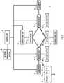
- FIG. 1there is a controller 20 that is in communication with classifier network nodes 30 and 35 and with a plurality of service nodes 40, 50, 60 and 70.
- the service nodes 40, 50, 60 and 70are also called network nodes herein and the classifier nodes 30 and 35 are also called head-end nodes.
- the service nodes 40, 50, 60 and 70host/support respective service functions or applications 42, 52, 62 and 72, each service function having a corresponding service-id.
- Service node 40is also denoted service-node 22
- service node 50is denoted service-node 27
- service node 60is denoted service-node 2
- service node 70is denoted service-node 57
- Service node 40hosts service-function 42 that is also denoted service-function 1
- Service node 50hosts service-function 52 that is also denoted service-function 2
- Service node 60hosts service-function 62 that is also denoted service-function 2
- Service node 70hosts service-function 72 that is also denoted service-function 3 .
- Some of the service-functions hosted by the service nodesare the same in the example of FIG. 1 .
- service node 50 and service node 60host service-functions 52 and 62, which are the same service-function, service-function 2 .
- service-function 2appears in multiple instances on different service nodes in the example scenario of FIG. 1 .
- network management station 80may be coupled to the controller 20 to communicate with the service nodes (or may communicate with the service nodes indirectly) in order to perform various network management functions as described herein.
- FIG. 1also shows an example of a packet 90 that passes through the head-end node 30.
- the packet 90includes payload 92 that is encapsulated in a Network Service Header (NSH) 100 and then encapsulated within a transport header (TH) 150.
- the NSH 100is metadata added to a packet or frame that is used to create a service plane.
- the payload 92 and the NSH 100are then encapsulated in an outer header, the TH 150, for transport.
- the NSH 100may be added by a service classification function, i.e., the head-node 30 (in the form of a device or application) that determines which packets require servicing, and correspondingly which service path to follow to apply the appropriate service.
- NSHNetwork Service Headers
- the NSH 100is designed to be easy to implement across a range of devices, both physical and virtual, including hardware forwarding elements.
- the NSH 100addresses several limitations associated with network service deployment today.
- Topological Dependenciesnetwork service deployments are often coupled to the physical network topology creating artificial constraints on delivery. These topologies serve only to "insert” the service function; they are not required from a native packet delivery perspective. For example, firewalls often require an "in” and “out” layer-2 segment and adding a new firewall requires changing the topology i.e. adding new layer-2 segments. This is restrictive because as more services are required - often with strict ordering - topology changes are needed before and after each service resulting in complex network changes and device configuration. In such topologies, all traffic, whether a service needs to be applied or not, will often pass through the same strict order.
- a common exampleis web servers using a server load balancer as the default gateway. When the web service responds to non-load balanced traffic (e.g. administrative or backup operations), all traffic from the server must traverse the load balancer forcing network administrators to create complex routing schemes or create additional interfaces to provide an alternate topology.
- Service Chainingservice functions are most typically independent, e.g. service-function-1 and service-function-2 are unrelated and there is no notion at the service layer that service-function-1 occurs before service-function-2. However, to an administrator many service functions have a strict ordering that must be in place yet there is no consistent way to impose and verify the deployed service ordering.
- Service Policy Applicationservice functions rely on either topology information such as virtual local area networks (VLANs) or packet (re)classification to determine service policy selection, the service action taken. Topology information is increasingly less viable due to scaling, tenancy, and complexity reasons. Per-service function packet classification is inefficient and prone to errors, duplicating functionality across services. Furthermore, packet classification is often too coarse lacking the ability to determine class of traffic with enough detail.
- topology informationsuch as virtual local area networks (VLANs) or packet (re)classification to determine service policy selection, the service action taken.
- Topology informationis increasingly less viable due to scaling, tenancy, and complexity reasons.
- Per-service function packet classificationis inefficient and prone to errors, duplicating functionality across services. Furthermore, packet classification is often too coarse lacking the ability to determine class of traffic with enough detail.
- Elastic Service Deliverygiven the current state of the art for adding/removing services largely centers around VLANs and routing changes, rapid changes to the service layer can be difficult to realize due to the risk and complexity of such changes.
- Common Header Formatvarious proprietary methods are used to share metadata and create service paths.
- An open headerprovides a common format for all network and service devices.
- Transport Agnosticservices can and will be deployed in networks with a range of transports, including underlays and overlays.
- the coupling of services to topologyrequires services to support many transports or for a transport gateway function to be present.
- FIG. 1shows at reference numeral 200 a primary service path for a service chain between Classifier 1 and Classifier 2 .
- the service pathis in "steady state" meaning it is operating normally and traffic is being forwarded and processed by service functions normally.
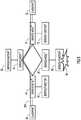
- FIGs. 2 and 3In or associated with service function 62 there is a monitoring process 64 deployed to detect failures or degradation of service within the service function 62. At 66, there is an OAM manager function located at the service node 60 deployed to receive a failure or degradation indication from the service function monitoring process 64.
- FIG. 3shows a failure or degradation of service 68 detected at the service function 62 and communicated by the monitoring process 64 to the OAM manager 66 of the service node 60 that is hosting the application/service function 62.
- the OAM manager 66correlates any associated failure/degradation information and proceeds to the next step of communicating the failure to other network elements such as upstream service nodes/load balancers, off-board OAM managers, and/or centralized service controllers/orchestration systems.
- a degradationmay involve a drop in the level of performance of a service function such as processing throughput within a specified range, packet drops above a certain threshold or availability of necessary internal resources to successfully process all packets sent through the service function.
- a failureis a complete or total failure in the ability of a service function to perform as it is designed to perform.
- the service node hosting the failed or degraded service functiongenerates metadata to include details of the application/service function failure and to be communicated either within the data plane to interested upstream network elements, or through whatever northbound protocol is appropriate for communication with a centralized service orchestration system generally represented by the controller 20 shown in FIG. 1 .
- a common headeris defined to be used for carrying metadata in a NSH 100 for Internet Protocol (IPv4), IPv6, and Multiprotocol Label Switching (MPLS) packets as shown in FIG. 4 .
- IPv4Internet Protocol
- IPv6IPv6
- MPLSMultiprotocol Label Switching
- the Metadata Channel Header 110provides for a "Metadata Channel Type” (MCT) that specifies the type of metadata carried within the packet.
- MCTMetal Channel Type
- Application/Service Function Failurea new MCT is defined called "Application/Service Function Failure” with a value equal to be determined. Details of the application/service function failure are carried within the Metadata Channel 112 that follows the Metadata Channel Header 110.
- the original payload of the packetis shown at 114 and is the original packet that was sent into the network. In this case, it would be blank or empty as the packet is generated by the service node that detects the service function failure.
- the NSH 100may be used to (i) identify the local service function that should have been applied to the packet, and (ii) extract the previous service hop information from the service-path mapping associated with that NSH.
- the NSH 100may be constructed as shown in FIGs. 5-7 .
- FIG. 5shows that the NSH 100 comprises a base service header 105 and an opaque service hop context header 120 that is carried as part of the NSH 100 to indicate the location information of the previous service hop and is used by the service node to identify which of the service functions within the service chain it should have applied and which of the service functions was applied at the previous service hop.
- the base service header 105may be composed of two words, but for simplicity it is shown as a single element in FIG. 2 .
- the base header 105provides information about the NSH 100 and service path identification.
- the base header 105includes a field 106 that contains certain flags described below, a protocol type field 107, a service index field 108 and a service path identifier field 109.
- the field 106includes an "O" bit and a "C” bit.
- the "O" bitis a one-bit flag that indicates whether a packet is an OAM packet. Participating nodes examine the payload and take appropriate action (i.e. return status information) when the "O" bit is set.
- the "C” bitindicates whether context headers are present. When the “C” bit is set, one or more contexts are in use (i.e. a value placed in a context is significant). The “C” bit specifies that the ordering and sizing of the contexts is predetermined, e.g., as shown in FIG. 4 described hereinafter. A “C” bit equal to zero indicates that no contexts are in use and that they can be ignored. If a context header is not in use, the value of that context header is zero.
- the protocol type field 107indicates the protocol type of the original packet or frame.
- the service index field 108specifies time-to-live (TTL) functionality and location within the service path. The service index is decremented by service nodes after performing required service function(s).
- the service path identifier field 109identifies a particular service path. A participating node uses this identifier for path selection.
- FIG. 7shows an example of the service hop context header 120.
- the service hop context header 120may specify the address of a previous service hop location. The contents of the header 120 is popped and pushed at each service hop along the service chain.
- An equivalent IPv6 context headermay also be defined.
- Each service path identifieris a unique value that points to an ordered list of service functions (e.g., service-function-1, service-function-2, service-function-3) and the service index is decremented by 1 at each service hop so that a Service Node receiving a packet prefaced with a NSH is able to identify which of the ordered list of service functions it should apply.
- the OAM manager function at the service node that is hosting the failed application/service functionis able to identify the previously applied service function and service hop and therefore send its metadata to that specific network node.
- Traffic bypass of the service node hosting a failed application/service functionis triggered through the receipt of the "Application/Service Function Failure" metadata (or NSH context header in lieu of the metadata MCT) at the previous service hop network element, or through instruction from an orchestration system.
- load balancersuse schemes to detect failures and take them out of their predictors. There are two key differences; (i) load balancers use signaling to achieve this rather than an explicit data plane trigger, and (ii) load balancers detect failures in the forwarding path (link/node failure) as opposed to failures at the application and/or service function layers.
- the techniques presented hereintrigger traffic bypass through receipt of failure information within the data plane. Receipt of the failure information forces a service node/load balancer to remove the failing elements from their predictors (or mark the next-hop as inoperative within their ECMP function) and select a different service hop from the updated set of available next-hops.
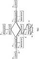
- FIG. 8shows an example of the bypass operation for the scenario described above in connection with FIGs. 2 and 3 .
- the primary service path 200is re-routed to bypass service function 62 (service-function 2 ) and instead pass through service node 50 that also hosts service-function 2 , the same service function that was being hosted at service node 60 but which suffered a failure or degradation at service node 60.
- the re-routed primary service pathis thus indicated by reference numeral 200' (200 prime).
- FIG. 9a flow chart is shown that depicts a process 300 for application/service function failure or degradation detection.
- a service function and/or application failureis detected by a monitoring process and communicated to an OAM manager at the hosting service node.
- the service nodegenerates metadata that is carried in a Metadata Channel Type defined as "Application/Service Function Failure".
- the service nodediscovers the previous service hop using the service hop context header received in the NSH from the previous service node of the service chain.
- the application/service function failure metadatais communicated to the previous service hop.
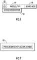
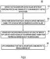
- FIG. 10shows a flow chart depicting a traffic bypass process 400 performed at the previous hop service node.
- the previous hop service nodereceives metadata indicating an application/service function failure at the next service hop of the service chain.
- the previous hop service nodemarks the next hop service node location as inoperative.
- the previous hop service nodeselects a new next service hop from set of available next-hops that serve the same service function or application as the failed or degraded one, if available, or otherwise selects the next service node as appropriate.
- the previous service hopsends traffic to the newly selected next service hop.
- techniquesare provided to (i) detect failures and/or function degradation at the application and/or service function layers, (ii) communicate details of the failure type through the advertisement of metadata in the data plane, and/or communicate details of the failure type through the advertisement of metadata to an off-board OAM manager or service controller/orchestration system, and (iii) provide application and/or service function failure bypass through manipulation of the service node/load balancer ECMP process.
- FIG. 11illustrates a technique that exploits the base service header of the NSH to allow a network operator to initiate a debugging/troubleshooting operation to have debugging data sent to an off-board OAM manager. This allows a network operator to take corrective action having discovered the last successfully applied service hop of the service path/service chain. A network operator would activate this operation upon detection of such failures along a service path.
- the base service header 105(as depicted in FIG. 6 ) defines an OAM (O) bit that indicates that the packet is an operations and management packet rather than user data. Receipt of such a packet at a service node forces the processing to be punted to an on-board OAM function therefore bypassing normal packet processing. This behavior may be undesirable for the purposes of debugging/troubleshooting, as the full end-to-end service path, as well as each service hop, needs to be exercised, and data collected at each service hop, to be able to determine the source of the failure.
- OAMOAM
- the (T) bit shown in FIG. 11provides another way to gather debugging and troubleshooting information about the packet and applied service functions at each service hop without altering the processing of the packet itself, having discovered the last successfully applied service hop of the service chain.
- the setting of the Tap (T) bit within the base service headerprovides an indication to a receiving service node that the service node should execute check pointing and/or collection of the packet payload and send debugging and/or troubleshooting information to an off-board OAM manager. This allows for the generation of debugging/troubleshooting data at each service hop along a given service path and continue normal packet processing without punting of the packet to an on-board OAM function.
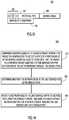
- FIG. 12illustrates a flow chart for a process 500 that exploits the use of the T bit described above in connection with FIG. 11 .
- the network nodeexamines a service header (e.g., NSH) of the received packet in which the packet is encapsulated to detect a state of a particular bit (e.g., T bit) in the service header allocated to command the collection of debugging information associated with the service function or application applied to traffic at the network node.
- the network nodegenerates debugging and/or troubleshooting information in response to detecting a particular state of the particular bit in the service header.
- the network nodesends the debugging and/or troubleshooting information to a destination for processing.
- the generation of the debugging and/or troubleshooting informationis performed without altering normal processing of traffic passing through the network node.
- the destination device or software processdetermines/identifies the last service function to have been successfully executed along a (failing service path) through generation of check pointing and/or collection of packet payload, to an off-board (centralized) OAM manager.
- FIGs. 11 and 12enable the collection of forensics information, to identify individual service hops on a service path that may be underdoing problems, without an OAM punt to a local OAM manager at each service node.
- FIG. 13a diagram is shown that is similar to that of FIG. 11 , but which includes a still further bit, called a V bit in the field 106 of the base service header 105.
- the V bitwhen set, indicates that the packet is a synthetic packet injected into the service path for verification of packet forwarding through the service chain.
- the V bitis set independently of the O bit thereby maintaining the ability to use normal OAM processing with network service headers if required. Receipt of a packet (with the V bit set) by the last service node within the service path indicates that the packet should not be forwarded after the last service function has been applied, but rather be dropped and an off-board OAM manager informed of the action.
- Synthetic user datais injected at the entry point into a service path, e.g., by a classifier (head-end node) in response to a command received from a controller 20 or network management station 80 ( FIG. 1 ), and is carried through the service path from ingress to egress with processing of the packet at each service hop.
- a classifierhead-end node
- Such trafficis forwarded through the same service path/service chain as user data but is intercepted at the exit point of the service path and not forwarded after the last service function has been applied. In this way a service path may be verified as operational from the data forwarding perspective.
- Synthetic packetsmay be used in two modes:
- the intelligence to decide when to inject a synthetic packetmay reside in the controller 20 shown in FIG. 1 , or in the network management station 80 also shown in FIG. 1 .
- FIG. 14is a flow chart for a process 600 performed at a service node for handling of a synthetic packet.
- the service nodeexamines a service header of a received packet in which the packet is encapsulated to detect a state of a particular bit in the service header allocated to indicate that the packet is a synthetic packet injected into the service path for verification of packet forwarding through the service path.
- the service nodedetermines whether it is the last service hop in the service path. This can be achieved by examining the service index in the base server header.
- the service nodedetermines that it is the last service hop in the service path, it drops the synthetic packet and sends a notification to a destination that the synthetic packet reached the last service hop in the service path.
- the destinationmay be the controller 20 and/or network management station 80 shown in FIG. 1 , and the receipt of this notification indicates that traffic has reached that last service hop in the service path, allowing for a determination of whether traffic is being properly forwarded in the service path by the service nodes.
- synthetic packetsmay be injected into the service path on an on-demand or periodic basis.
- the techniques depicted in FIGs. 13 and 14provide for a method for verification of a service path that does not rely upon user traffic or on-board OAM processing logic but rather uses the functions of service headers in the data plane, and therefore verifies the same forwarding path as that used for user data through the service chain.
- Context verificationcan be made for any packet, any tenant, and any service.
- these techniquescan be used as a "Service Trace Route" function e.g., it can be activated on every 'n'th user packet to keep track of the health of the service path. There is total flexibility in the crafting of synthetic user packets and all service headers, with complete control over what functionality along a service path is tested.
- FIG. 15illustrates an example block diagram for a network/service node, e.g., a switch, router, gateway, etc., configured to perform the operations described herein for a network node.
- a virtual network nodewould be a software-emulated or virtualized version of what is shown in FIG. 15 .
- the network node 700comprises a plurality of ports 710(1)-710(m), a network Application Specific Integrated Circuit (ASIC) 715, a processor or central processing unit (CPU) 720 and memory 730.
- the ports 710(1)-710(m)receive ingress packets and output egress packets from the network node.
- the network node ASIC 720directs incoming packets to ports for egress according to logic as well as controls from the processor 720. For example, if the network node is a router, then the ASIC 715 is a router ASIC configured for network routing functions, and if the network node is a switch, then the ASIC 715 is a switch ASIC configured for network switch functions.
- the processor 720is a microprocessor or microcontroller, for example, and executes instructions for the service header processing firmware/software 740 stored in memory 730.
- the service header processing firmware/software 740 and OAM manager software 750include instructions that, when executed by the processor 720, cause the processor to perform the operations described herein in connection with FIGs. 1-14 for a network node/service node.
- the operations of a service function or application associated with network node 700are implemented by service function or application software 770 running on a processor core or server blade 760 that is in communication with a port, e.g., port 710(m), of the network node.
- service function or application software 770running on a processor core or server blade 760 that is in communication with a port, e.g., port 710(m), of the network node.
- monitoring software 780running on the processor core or server blade 760 to perform monitoring of the service function in order to detect when a degradation or failure occurs in the associated service function or application at the network node.
- the monitoring software 780performs the aforementioned monitoring process shown at reference numeral 64 in FIGs. 2 and 3 .
- the memory 730may comprise read only memory (ROM), random access memory (RAM), magnetic disk storage media devices, optical storage media devices, flash memory devices, electrical, optical, or other physical/tangible memory storage devices.
- the memory 730may comprise one or more tangible (non-transitory) computer readable storage media (e.g., a memory device) encoded with software comprising computer executable instructions and when the software is executed (by the processor 720) it is operable to perform the operations described herein.
- FIG. 16an example block diagram is shown for a controller configured to perform the operations described herein for controller 20.
- a virtual controllerwould be a software-emulated or virtualized version of what is shown in FIG. 16 , such as software running in a data center.
- the controller 20includes one or more processors 810, memory 820, a bus 830 and a network interface unit 840.
- the processor 810may be a microprocessor or microcontroller.
- the network interface unit 840facilitates network communications between the controller 20 and the network nodes.
- the processor 810executes instructions associated with software stored in memory 820. Specifically, the processor 810 stores service path and service header generation software 850 that, when executed by the processor 810, causes the processor 810 to perform the operations for the controller 20 and/or network management station 80 described herein with respect to FIGs. 1-14 .
- the memory 820may comprise read only memory (ROM), random access memory (RAM), magnetic disk storage media devices, optical storage media devices, flash memory devices, electrical, optical, or other physical/tangible memory storage devices.
- the memory 820may comprise one or more tangible (non-transitory) computer readable storage media (e.g., a memory device) encoded with software comprising computer executable instructions and when the software is executed (by the processor 810) it is operable to perform the operations described herein.
- the techniques presented hereinmay be embodied in a method, an apparatus and computer readable storage media, for example.
- the methodinvolves, in a network comprising a plurality of network nodes each configured to apply one or more service functions to traffic that passes the respective network nodes in a service path, receiving at a network node an indication of a failure or degradation of a service function or application applied to traffic at the network node; generating data descriptive of the failure or degradation; determining a previous service hop network node at which a service function or application was applied to traffic in the service path; and communicating the data descriptive of the failure or degradation to the previous service hop network node.
- an apparatuscomprising a network interface unit configured to enable communications over a network, the network comprising a plurality of network nodes each configured to apply one or more service functions to traffic that passes through the respective network nodes; memory; and a processor coupled to the network interface unit and the memory, wherein the processor is configured to: receive at a network node an indication of a failure or degradation of a service function or application applied to traffic at the network node; generate data descriptive of the failure or degradation; determine a previous service hop network node at which a service function or application was applied to traffic in the service path; and communicate the data descriptive of the failure or degradation to the previous service hop network node.
- one or more computer readable storage mediaare provided encoded with software comprising computer executable instructions and when the software is executed operable to: receive at a network node an indication of a failure or degradation of a service function or application applied to traffic at the network node; generate data descriptive of the failure or degradation; determine a previous service hop network node at which a service function or application was applied to traffic in the service path; and communicate the data descriptive of the failure or degradation to the previous service hop network node.
Landscapes
- Engineering & Computer Science (AREA)
- Computer Networks & Wireless Communication (AREA)
- Signal Processing (AREA)
- Quality & Reliability (AREA)
- Environmental & Geological Engineering (AREA)
- Data Exchanges In Wide-Area Networks (AREA)
- Mobile Radio Communication Systems (AREA)
Description
- The present disclosure relates to networking for service chains/service paths.
- Network services are widely deployed and essential in many networks. The services provide a range of functions such as security, wide area network (WAN) acceleration, firewall services, and server load balancing. Service functions that form part of the overall service may be physically located at different points in the network infrastructure, such as the wide area network, data center, campus, and so forth.
- Current network service deployment models are relatively static, and bound to topology for insertion and policy selection. Furthermore, they do not adapt well to elastic service environments enabled by virtualization.
- New data center network and cloud architectures require more flexible network service deployment models. Additionally, the transition to virtual platforms requires an agile service insertion model that supports elastic service delivery. The movement of service functions and application workloads in the network and the ability to easily bind service policy to granular information such as per-subscriber state are particularly useful.
- Background art is provided in a paper entitled "Design Considerations for Session Initiation Protocol (SIP) Overload Control" by V. Hilt et al. (Internet Engineering Task Force, Request for Comments 6357, rfc6357.txt, August 2011) and in a paper entitled "A Policy-aware Switching Layer for Data Centers" by D.A. Joseph et al. (retrieved via http://ccr.sigcomm.org/online/files/p51-josephA.pdf, June 2008).
- The paper by Hilt et al. states that overload can occur in Session Initiation Protocol (SIP) networks when SIP servers have insufficient resources to handle all SIP messages they receive. It is mentioned that, even though the SIP protocol provides a limited overload control mechanism through its 503 (Service Unavailable) response code, SIP servers are still vulnerable to overload. The paper goes on to discuss models and design considerations for a SIP overload control mechanism.
- The paper by Joseph et al. proposes a policy-aware switching layer or "PLayer", a layer-2 for data centers consisting of inter-connected policy-aware switches or "pswitches". Unmodified middleboxes (e.g., firewalls, load balancers and SSL offloaders) are placed off the network path by plugging them into "pswitches". Based on policies specified by administrators, "pswitches" explicitly forward different types of traffic through different sequences of middleboxes.
- The present invention is a method as defined in
Claim 1 of the appended claims. Also provided is an apparatus as defined in Claim 13, and computer readable storage media encoded with software as defined in Claim 14. FIG. 1 is a block diagram of an example arrangement of service nodes in a network and a service path is created to apply service functions or applications to traffic.FIG. 2 is a block diagram similar toFIG. 1 , but showing monitoring for degradation or failure of a service function at a service node.FIG. 3 is a block diagram similar toFIG. 2 , but showing detection of degradation or failure of a service function at a service node.FIG. 4 is a diagram of a Metadata Channel Header used to carry information indicating detection of a failure or degradation of a service function at a service node.FIG. 5 is a diagram of a service header that includes a base service header and a service hop context header configured to carry information indicating detection of a failure or degradation of a service function at a service node.FIG. 6 is a more detailed diagram showing an example of the base service header.FIG. 7 is a diagram showing an example of the service hop context header.FIG. 8 is a diagram similar toFIG. 3 , but showing bypass or re-routing a service path around a service function experiencing degradation or failure.FIG. 9 is a flow chart of operations performed at a service node that is hosting a service function or application experiencing a failure or degradation.FIG. 10 is a flow chart of operations performed at a service node that receives information indicating that the service function at the next hop is experiencing a failure and thus traffic should bypass that service node.FIG. 11 is a diagram of another form of the base service header configured to include information indicating that a service node that receives the packet is to generate debugging and/or troubleshooting information for a service function or application applied at that service node.FIG. 12 is a flow chart depicting operations performed at a service node that receives a packet encapsulated with a base service header as depicted inFIG. 11 .FIG. 13 is a diagram of still another form of the base service header configured to include information indicating that the packet is a synthetic packet and should be forwarded as normal traffic for the service path to allow for forwarding verification of the service path.FIG. 14 is a flow chart depicting operations performed at a service node that receives a packet encapsulated with a base service header as depicted inFIG. 13 .FIG. 15 is an example of a block diagram of a network node configured to perform the techniques presented herein.FIG. 16 is an example of a block diagram of a controller and/or network management station that is configured to perform the techniques presented herein.- Presented herein are techniques performed in a network comprising a plurality of network nodes each configured to apply one or more service functions to traffic that passes the respective network nodes in a service path. At a network node, an indication is received of a failure or degradation of one or more service functions or applications applied to traffic at the network node. Data descriptive of the failure or degradation is generated. A previous service hop network node at which a service function or application was applied to traffic in the service path is determined. The data descriptive of the failure or degradation is communicated to the previous service hop network node.
- A service chain is defined as a set of service functions, e.g., firewall, network address translation (NAT), deep packet inspection (DPI), intrusion detection service (IDS), and the order in which they should be applied to selective packets as they are forwarded through a service-path. This form of service chaining, while useful, does not provide enough functionality for the delivery of more complex services that rely upon the binding of service policy to granular information such as per-subscriber state, or receipt of metadata specifically formatted for consumption by a particular service function. Examples of metadata specifically formatted for consumption by a service function include application identification, network forwarding context, flow identifier and user identity. Such advanced services require that service context and metadata be carried within service headers as part of the data-plane encapsulation.
- Service chain construction involves establishment of a binding between forwarding state and the service chain. This mapping of forwarding-state to the service chain defines the service path and is most typically formed using a network overlay. Service nodes perform operations and service functions on packets that are forwarded through the service path.
- While the control and data-plane elements of a service path are well understood, it is not currently possible to determine which service hop was the last successful one to have been applied should failures such as black holing, dropping, or incorrect forwarding of packets occur along the service path. This creates an operational/security problem, as packets may not reach the expected service nodes as defined by the appropriate service policies or worse still have service functions misapplied to them. These two issues are critical problems to solve: the operational/security implications such as the wrong firewall policy being applied to the traffic threaten the robustness of the solution.
- All of these issues result in the same observed behavior. Operators/customers do not see the end-to-end packet flow as traffic passes through each service hop along the service path. The goal therefore is to identify which is the root cause and at which service hop/service node.
- There is a need for a solution that is able to detect failures and/or function degradation at the application and/or service function layer so that preventative measures may be taken to bypass the failure. In addition, such a solution should either provide the methods necessary for communication of said failures using the data plane to upstream service nodes/load balancers, and/or send notifications and details of the failure type to an off-board Operations and Management (OAM) manager, or service controller/orchestration system.
- According to one aspect of the techniques presented herein, a method is provided to (i) detect failures and/or function degradation at the application and/or service function layers, (ii) communicate details of the failure type through the advertisement of metadata in the data plane, and/or communicate details of the failure type through the advertisement of metadata to an off-board OAM manager or service controller/orchestration system, and (iii) provide application and/or service function failure bypass through manipulation of the service node/load balancer Equal Cost Multiple Path (ECMP) process. ECMP is a routing strategy in which next-hop packet forwarding to a single destination can occur over multiple "best paths" which tie for top place in routing metric calculations.
- According to another aspect of the techniques presented herein, a network operator may activate a troubleshooting function upon detection of such failures along a service path, to allow for debugging/troubleshooting data to be sent to an off-board OAM manager so that the network operator may take corrective action having discovered the last successfully applied service hop of the service path/service chain.
- Verification of the integrity and forwarding state of a service path is a fundamental requirement for any network operator. Currently, this verification process may be performed in one of two ways; (i) using real user traffic, and (ii) using OAM packets that may be forwarded to an on-board OAM function at a service node to verify operation and status of a given service function. However, both of these methods present challenges that do not fully satisfy all verification requirements.
- Using real user traffic for verification of a service path has the implication that a user traffic flow is effectively "hijacked" for OAM purposes; this is not only undesirable but presents issues with regards to billing and service level agreement management. Using OAM packets punted to an on-board OAM function does not truly verify the service path as such OAM packets are taken from the normal processing path at each service hop and are presented to an OAM processing module for verification.
- Thus, according to still another aspect, techniques are presented herein for service path verification that do not rely upon user traffic or an on-board OAM processing module but rather use the functions of Network Service Headers (NSHs) and therefore verifies the same forwarding path as that used for user data sent through the service chain.
- In accordance with the techniques presented herein, service nodes utilize information carried within service headers in the data-plane, such as network classification used for deriving targeted service policies and profiles. Service nodes may also determine common metadata related to a particular service such as finer classification that can be passed to the service functions further down the service-path. In other words, services benefit from metadata derived both from the network as well as the service functions that form a given service chain. Metadata can also be passed from network node to network node with a service between network nodes.
- The metadata imposed by the network node originating the service chain is a combination of the metadata pushed by a central controller and metadata determined by the network node itself. Controllers push network classification specific metadata to all the network nodes that act as classifiers. These network nodes perform the classification and choose the assigned metadata for that classification along with the forwarding state. The determined metadata could be related to aspects of the service topology such as tenant identity. The implication of associating such metadata to the forwarding state and passing it to the functions that provide services is that more complex services can be delivered, for instance, on a tenant boundary for a given service-path. This can result in simpler services because the services do not need to derive information or re-classify every packet/flow.
- Reference is now made to
FIG. 1 for a description of an example network environment in which the techniques presented herein may be employed. In the example ofFIG. 1 , there is acontroller 20 that is in communication withclassifier network nodes service nodes service nodes classifier nodes service nodes applications Service node 40 is also denoted service-node22,service node 50 is denoted service-node27,service node 60 is denoted service-node2, andservice node 70 is denoted service-node57.Service node 40 hosts service-function 42 that is also denoted service-function1.Service node 50 hosts service-function 52 that is also denoted service-function2.Service node 60 hosts service-function 62 that is also denoted service-function2.Service node 70 hosts service-function 72 that is also denoted service-function3. Some of the service-functions hosted by the service nodes are the same in the example ofFIG. 1 . Specifically,service node 50 andservice node 60 host service-functions FIG. 1 . - There is also a
network management station 80 that may be coupled to thecontroller 20 to communicate with the service nodes (or may communicate with the service nodes indirectly) in order to perform various network management functions as described herein. FIG. 1 also shows an example of apacket 90 that passes through the head-end node 30. Thepacket 90 includespayload 92 that is encapsulated in a Network Service Header (NSH) 100 and then encapsulated within a transport header (TH) 150. TheNSH 100 is metadata added to a packet or frame that is used to create a service plane. Thepayload 92 and theNSH 100 are then encapsulated in an outer header, theTH 150, for transport. TheNSH 100 may be added by a service classification function, i.e., the head-node 30 (in the form of a device or application) that determines which packets require servicing, and correspondingly which service path to follow to apply the appropriate service.- Service chaining techniques are enabled through the use of transport independent Network Service Headers (NSH) in the data plane. The
NSH 100 comprises a plurality of headers, and as will become apparent, these headers contain service related information and have two main elements: - 1. A fixed sized, transport independent per-packet/frame service metadata.
- 2. Data plane encapsulation that utilizes the network overlay topology to deliver packets to the requisite services.
- The
NSH 100 is designed to be easy to implement across a range of devices, both physical and virtual, including hardware forwarding elements. TheNSH 100 addresses several limitations associated with network service deployment today. - Topological Dependencies: network service deployments are often coupled to the physical network topology creating artificial constraints on delivery. These topologies serve only to "insert" the service function; they are not required from a native packet delivery perspective. For example, firewalls often require an "in" and "out" layer-2 segment and adding a new firewall requires changing the topology i.e. adding new layer-2 segments. This is restrictive because as more services are required - often with strict ordering - topology changes are needed before and after each service resulting in complex network changes and device configuration. In such topologies, all traffic, whether a service needs to be applied or not, will often pass through the same strict order. A common example is web servers using a server load balancer as the default gateway. When the web service responds to non-load balanced traffic (e.g. administrative or backup operations), all traffic from the server must traverse the load balancer forcing network administrators to create complex routing schemes or create additional interfaces to provide an alternate topology.
- Service Chaining: service functions are most typically independent, e.g. service-function-1 and service-function-2 are unrelated and there is no notion at the service layer that service-function-1 occurs before service-function-2. However, to an administrator many service functions have a strict ordering that must be in place yet there is no consistent way to impose and verify the deployed service ordering.
- Service Policy Application: service functions rely on either topology information such as virtual local area networks (VLANs) or packet (re)classification to determine service policy selection, the service action taken. Topology information is increasingly less viable due to scaling, tenancy, and complexity reasons. Per-service function packet classification is inefficient and prone to errors, duplicating functionality across services. Furthermore, packet classification is often too coarse lacking the ability to determine class of traffic with enough detail.
- Elastic Service Delivery: given the current state of the art for adding/removing services largely centers around VLANs and routing changes, rapid changes to the service layer can be difficult to realize due to the risk and complexity of such changes.
- Common Header Format: various proprietary methods are used to share metadata and create service paths. An open header provides a common format for all network and service devices.
- Transport Agnostic: services can and will be deployed in networks with a range of transports, including underlays and overlays. The coupling of services to topology requires services to support many transports or for a transport gateway function to be present.
FIG. 1 shows at reference numeral 200 a primary service path for a service chain between Classifier1 and Classifier2. At this time, as shown inFIG. 1 , the service path is in "steady state" meaning it is operating normally and traffic is being forwarded and processed by service functions normally.- There are three operational phases that work in tandem to detect and bypass an application/service function failure/degradation:
- 1. Application/service function layer failure detection; and
- 2. Advertisement of application/service function failure type through the use of metadata; and
- 3. Automatic traffic bypass of the service node hosting the failed application/service function.
- There are many reasons why an application/service function might fail and it is not always possible to detect such failures at the transport layer, as the underlying packet forwarding through the overlay network may be fully operational. Furthermore, complete application/service function failure is only one of the possible failure types; others include functional degradation, performance degradation above and beyond a specified threshold, unrelated failure of the network element hosting the application/service function, etc.
- Reference is now made to
FIGs. 2 and3 . In or associated withservice function 62 there is amonitoring process 64 deployed to detect failures or degradation of service within theservice function 62. At 66, there is an OAM manager function located at theservice node 60 deployed to receive a failure or degradation indication from the servicefunction monitoring process 64. FIG. 3 shows a failure or degradation ofservice 68 detected at theservice function 62 and communicated by themonitoring process 64 to theOAM manager 66 of theservice node 60 that is hosting the application/service function 62. Upon notification of the failure, theOAM manager 66 correlates any associated failure/degradation information and proceeds to the next step of communicating the failure to other network elements such as upstream service nodes/load balancers, off-board OAM managers, and/or centralized service controllers/orchestration systems. A degradation may involve a drop in the level of performance of a service function such as processing throughput within a specified range, packet drops above a certain threshold or availability of necessary internal resources to successfully process all packets sent through the service function. By contrast, a failure is a complete or total failure in the ability of a service function to perform as it is designed to perform.- Once an application/service function failure or degradation has been detected and reported to the OAM manager of the hosting service node, it is necessary that other network elements be informed so that corrective action may be taken to bypass the failure. This may be achieved in a distributed or centralized fashion by communicating the failure through the data plane (as opposed to using a signaling protocol for this purpose such as is done today for transport link/node failures) to upstream network elements (distributed), or by advertising the failure to an off-board OAM manager or centralized service orchestration controller (centralized).
- Accordingly, the service node hosting the failed or degraded service function generates metadata to include details of the application/service function failure and to be communicated either within the data plane to interested upstream network elements, or through whatever northbound protocol is appropriate for communication with a centralized service orchestration system generally represented by the
controller 20 shown inFIG. 1 . - To communicate application/service function failure metadata, in accordance with one example, a common header is defined to be used for carrying metadata in a
NSH 100 for Internet Protocol (IPv4), IPv6, and Multiprotocol Label Switching (MPLS) packets as shown inFIG. 4 . - The
Metadata Channel Header 110 provides for a "Metadata Channel Type" (MCT) that specifies the type of metadata carried within the packet. For the purposes of these techniques, a new MCT is defined called "Application/Service Function Failure" with a value equal to be determined. Details of the application/service function failure are carried within theMetadata Channel 112 that follows theMetadata Channel Header 110. The original payload of the packet is shown at 114 and is the original packet that was sent into the network. In this case, it would be blank or empty as the packet is generated by the service node that detects the service function failure. - As an alternative to the Common Metadata Header it is also possible to carry the application/service function failure information within the NSH (through definition of an opaque context header defined for that purpose). In order for a service node (that is hosting a failed or degraded service function) to know which particular upstream network elements to advertise the metadata to, the
NSH 100 referred to above in connection withFIG. 1 may be used to (i) identify the local service function that should have been applied to the packet, and (ii) extract the previous service hop information from the service-path mapping associated with that NSH. - The
NSH 100 may be constructed as shown inFIGs. 5-7 .FIG. 5 shows that theNSH 100 comprises abase service header 105 and an opaque servicehop context header 120 that is carried as part of theNSH 100 to indicate the location information of the previous service hop and is used by the service node to identify which of the service functions within the service chain it should have applied and which of the service functions was applied at the previous service hop. - One form of the
base service header 105 is shown in more detail inFIG. 6 . Thebase header 105 may be composed of two words, but for simplicity it is shown as a single element inFIG. 2 . Thebase header 105 provides information about theNSH 100 and service path identification. Thebase header 105 includes afield 106 that contains certain flags described below, aprotocol type field 107, aservice index field 108 and a servicepath identifier field 109. Thefield 106 includes an "O" bit and a "C" bit. The "O" bit is a one-bit flag that indicates whether a packet is an OAM packet. Participating nodes examine the payload and take appropriate action (i.e. return status information) when the "O" bit is set. The "C" bit indicates whether context headers are present. When the "C" bit is set, one or more contexts are in use (i.e. a value placed in a context is significant). The "C" bit specifies that the ordering and sizing of the contexts is predetermined, e.g., as shown inFIG. 4 described hereinafter. A "C" bit equal to zero indicates that no contexts are in use and that they can be ignored. If a context header is not in use, the value of that context header is zero. - The
protocol type field 107 indicates the protocol type of the original packet or frame. Theservice index field 108 specifies time-to-live (TTL) functionality and location within the service path. The service index is decremented by service nodes after performing required service function(s). - The service
path identifier field 109 identifies a particular service path. A participating node uses this identifier for path selection. FIG. 7 shows an example of the servicehop context header 120. In one example, the servicehop context header 120 may specify the address of a previous service hop location. The contents of theheader 120 is popped and pushed at each service hop along the service chain. An equivalent IPv6 context header may also be defined.- The combination of the service path identifier and service index carried within the NSH is used for identification of which specific service functions should be applied to packets. Each service path identifier is a unique value that points to an ordered list of service functions (e.g., service-function-1, service-function-2, service-function-3) and the service index is decremented by 1 at each service hop so that a Service Node receiving a packet prefaced with a NSH is able to identify which of the ordered list of service functions it should apply.
- Using this mechanism combined with the service
hop context header 120, the OAM manager function at the service node that is hosting the failed application/service function is able to identify the previously applied service function and service hop and therefore send its metadata to that specific network node. - Traffic bypass of the service node hosting a failed application/service function is triggered through the receipt of the "Application/Service Function Failure" metadata (or NSH context header in lieu of the metadata MCT) at the previous service hop network element, or through instruction from an orchestration system.
- In current networking systems, load balancers use schemes to detect failures and take them out of their predictors. There are two key differences; (i) load balancers use signaling to achieve this rather than an explicit data plane trigger, and (ii) load balancers detect failures in the forwarding path (link/node failure) as opposed to failures at the application and/or service function layers.
- By contrast, the techniques presented herein trigger traffic bypass through receipt of failure information within the data plane. Receipt of the failure information forces a service node/load balancer to remove the failing elements from their predictors (or mark the next-hop as inoperative within their ECMP function) and select a different service hop from the updated set of available next-hops.
FIG. 8 shows an example of the bypass operation for the scenario described above in connection withFIGs. 2 and3 . After thefailure 68 ofservice function 62, theprimary service path 200 is re-routed to bypass service function 62 (service-function2) and instead pass throughservice node 50 that also hosts service-function2, the same service function that was being hosted atservice node 60 but which suffered a failure or degradation atservice node 60. The re-routed primary service path is thus indicated byreference numeral 200' (200 prime).- Turning to
FIG. 9 , a flow chart is shown that depicts aprocess 300 for application/service function failure or degradation detection. At 310, a service function and/or application failure is detected by a monitoring process and communicated to an OAM manager at the hosting service node. At 320, the service node generates metadata that is carried in a Metadata Channel Type defined as "Application/Service Function Failure". At 330, the service node discovers the previous service hop using the service hop context header received in the NSH from the previous service node of the service chain. At 340, the application/service function failure metadata is communicated to the previous service hop. FIG. 10 shows a flow chart depicting atraffic bypass process 400 performed at the previous hop service node. At 410, the previous hop service node receives metadata indicating an application/service function failure at the next service hop of the service chain. At 420, the previous hop service node marks the next hop service node location as inoperative. At 430, the previous hop service node selects a new next service hop from set of available next-hops that serve the same service function or application as the failed or degraded one, if available, or otherwise selects the next service node as appropriate. At 440, the previous service hop sends traffic to the newly selected next service hop.- In summary of the concepts presented above in connection with
FIGs. 1-10 , techniques are provided to (i) detect failures and/or function degradation at the application and/or service function layers, (ii) communicate details of the failure type through the advertisement of metadata in the data plane, and/or communicate details of the failure type through the advertisement of metadata to an off-board OAM manager or service controller/orchestration system, and (iii) provide application and/or service function failure bypass through manipulation of the service node/load balancer ECMP process. - There are numerous advantages associated with these techniques. They provide the capability to generate "application/service function failure" metadata or NSH opaque context headers, from an OAM manager function at a service node upon detection of failure or degradation of functionality. This enables identification of the previous service hop of a service chain and advertisement of the generated metadata to the previous service hop network element so as to trigger automatic traffic bypass of the failing or degraded service node. In addition, a service node/load balancer can trigger traffic bypass by manipulation of their ECMP decision process through correlation of the "application/service function failure" metadata or NSH opaque context headers, and available service node next-hops for the required service function. Further still, these techniques allow for the correlation of "application/service function failure" metadata or opaque NSH context headers at an off-board OAM manager and/or centralized controller/orchestration system.
- Reference is now made to
FIG. 11. FIG. 11 illustrates a technique that exploits the base service header of the NSH to allow a network operator to initiate a debugging/troubleshooting operation to have debugging data sent to an off-board OAM manager. This allows a network operator to take corrective action having discovered the last successfully applied service hop of the service path/service chain. A network operator would activate this operation upon detection of such failures along a service path. - The base service header 105 (as depicted in
FIG. 6 ) defines an OAM (O) bit that indicates that the packet is an operations and management packet rather than user data. Receipt of such a packet at a service node forces the processing to be punted to an on-board OAM function therefore bypassing normal packet processing. This behavior may be undesirable for the purposes of debugging/troubleshooting, as the full end-to-end service path, as well as each service hop, needs to be exercised, and data collected at each service hop, to be able to determine the source of the failure. - The (T) bit shown in
FIG. 11 provides another way to gather debugging and troubleshooting information about the packet and applied service functions at each service hop without altering the processing of the packet itself, having discovered the last successfully applied service hop of the service chain. The setting of the Tap (T) bit within the base service header provides an indication to a receiving service node that the service node should execute check pointing and/or collection of the packet payload and send debugging and/or troubleshooting information to an off-board OAM manager. This allows for the generation of debugging/troubleshooting data at each service hop along a given service path and continue normal packet processing without punting of the packet to an on-board OAM function. - Normal processing of the packet through the service path continues so that each service node along the service path is forced to generate debugging/troubleshooting information that can be correlated at an off-board OAM manager so that corrective action may be taken by the network operator or orchestration system having discovered the last successfully applied service hop of the service chain. An example of an off-board OAM manager is the
network management station 80 shown inFIG. 1 . FIG. 12 illustrates a flow chart for aprocess 500 that exploits the use of the T bit described above in connection withFIG. 11 . At 510, at a network node that receives a packet, the network node examines a service header (e.g., NSH) of the received packet in which the packet is encapsulated to detect a state of a particular bit (e.g., T bit) in the service header allocated to command the collection of debugging information associated with the service function or application applied to traffic at the network node. At 520, the network node generates debugging and/or troubleshooting information in response to detecting a particular state of the particular bit in the service header. At 530, the network node sends the debugging and/or troubleshooting information to a destination for processing. The generation of the debugging and/or troubleshooting information is performed without altering normal processing of traffic passing through the network node. The destination device or software process (off-board OAM manager) determines/identifies the last service function to have been successfully executed along a (failing service path) through generation of check pointing and/or collection of packet payload, to an off-board (centralized) OAM manager. Again, the techniques depicted byFIGs. 11 and 12 enable the collection of forensics information, to identify individual service hops on a service path that may be underdoing problems, without an OAM punt to a local OAM manager at each service node.- Turning to
FIG. 13 , a diagram is shown that is similar to that ofFIG. 11 , but which includes a still further bit, called a V bit in thefield 106 of thebase service header 105. The V bit, when set, indicates that the packet is a synthetic packet injected into the service path for verification of packet forwarding through the service chain. The V bit is set independently of the O bit thereby maintaining the ability to use normal OAM processing with network service headers if required. Receipt of a packet (with the V bit set) by the last service node within the service path indicates that the packet should not be forwarded after the last service function has been applied, but rather be dropped and an off-board OAM manager informed of the action. - Synthetic user data is injected at the entry point into a service path, e.g., by a classifier (head-end node) in response to a command received from a
controller 20 or network management station 80 (FIG. 1 ), and is carried through the service path from ingress to egress with processing of the packet at each service hop. Such traffic is forwarded through the same service path/service chain as user data but is intercepted at the exit point of the service path and not forwarded after the last service function has been applied. In this way a service path may be verified as operational from the data forwarding perspective. - Synthetic packets may be used in two modes:
- 1. On-demand: a user-triggered event starts the transmission of the synthetic packet.
- 2. Periodic: periodically a user packet is copied at the ingress to a service path and that packet copy is marked with the V bit and injected into the service path.
- Additionally, two modes for verification of the service path may be defined:
- 1. Path Connectivity Check: use of the V bit as described above.
- 2. Detailed Path Service Verification: use of the V bit in combination with the T bit described above.
- The intelligence to decide when to inject a synthetic packet may reside in the
controller 20 shown inFIG. 1 , or in thenetwork management station 80 also shown inFIG. 1 . FIG. 14 is a flow chart for aprocess 600 performed at a service node for handling of a synthetic packet. At 610, the service node examines a service header of a received packet in which the packet is encapsulated to detect a state of a particular bit in the service header allocated to indicate that the packet is a synthetic packet injected into the service path for verification of packet forwarding through the service path. At 620, the service node determines whether it is the last service hop in the service path. This can be achieved by examining the service index in the base server header. At 630, when the service node determines that it is the last service hop in the service path, it drops the synthetic packet and sends a notification to a destination that the synthetic packet reached the last service hop in the service path. The destination may be thecontroller 20 and/ornetwork management station 80 shown inFIG. 1 , and the receipt of this notification indicates that traffic has reached that last service hop in the service path, allowing for a determination of whether traffic is being properly forwarded in the service path by the service nodes. As explained above, synthetic packets may be injected into the service path on an on-demand or periodic basis.- Thus, the techniques depicted in
FIGs. 13 and 14 provide for a method for verification of a service path that does not rely upon user traffic or on-board OAM processing logic but rather uses the functions of service headers in the data plane, and therefore verifies the same forwarding path as that used for user data through the service chain. Context verification can be made for any packet, any tenant, and any service. Finally, these techniques can be used as a "Service Trace Route" function e.g., it can be activated on every 'n'th user packet to keep track of the health of the service path. There is total flexibility in the crafting of synthetic user packets and all service headers, with complete control over what functionality along a service path is tested. These techniques allow for testing of the end-to-end "service connectivity", but also to verify service program, context, and service functions. Synthetic service information is created, injected for context, path, and service verification for any tenant, any packet, and any service, in a way that fate shares with user data but does not impact end-users. This service verification is indistinguishable from user data but does not get exposed to a customer. It achieves verification of a service path without relying upon punted OAM processing hop-by-hop through the service path. FIG. 15 illustrates an example block diagram for a network/service node, e.g., a switch, router, gateway, etc., configured to perform the operations described herein for a network node. It should be understood that a virtual network node would be a software-emulated or virtualized version of what is shown inFIG. 15 . Thenetwork node 700 comprises a plurality of ports 710(1)-710(m), a network Application Specific Integrated Circuit (ASIC) 715, a processor or central processing unit (CPU) 720 andmemory 730. The ports 710(1)-710(m) receive ingress packets and output egress packets from the network node. Thenetwork node ASIC 720 directs incoming packets to ports for egress according to logic as well as controls from theprocessor 720. For example, if the network node is a router, then theASIC 715 is a router ASIC configured for network routing functions, and if the network node is a switch, then theASIC 715 is a switch ASIC configured for network switch functions. Theprocessor 720 is a microprocessor or microcontroller, for example, and executes instructions for the service header processing firmware/software 740 stored inmemory 730. The service header processing firmware/software 740 andOAM manager software 750 include instructions that, when executed by theprocessor 720, cause the processor to perform the operations described herein in connection withFIGs. 1-14 for a network node/service node.- The operations of a service function or application associated with
network node 700 are implemented by service function orapplication software 770 running on a processor core orserver blade 760 that is in communication with a port, e.g., port 710(m), of the network node. In addition, there is monitoringsoftware 780 running on the processor core orserver blade 760 to perform monitoring of the service function in order to detect when a degradation or failure occurs in the associated service function or application at the network node. Themonitoring software 780 performs the aforementioned monitoring process shown atreference numeral 64 inFIGs. 2 and3 . - The
memory 730 may comprise read only memory (ROM), random access memory (RAM), magnetic disk storage media devices, optical storage media devices, flash memory devices, electrical, optical, or other physical/tangible memory storage devices. In general, thememory 730 may comprise one or more tangible (non-transitory) computer readable storage media (e.g., a memory device) encoded with software comprising computer executable instructions and when the software is executed (by the processor 720) it is operable to perform the operations described herein. - Turning now to
FIG. 16 , an example block diagram is shown for a controller configured to perform the operations described herein forcontroller 20. It should be understood that a virtual controller would be a software-emulated or virtualized version of what is shown inFIG. 16 , such as software running in a data center. Thecontroller 20 includes one ormore processors 810,memory 820, abus 830 and anetwork interface unit 840. Theprocessor 810 may be a microprocessor or microcontroller. Thenetwork interface unit 840 facilitates network communications between thecontroller 20 and the network nodes. Theprocessor 810 executes instructions associated with software stored inmemory 820. Specifically, theprocessor 810 stores service path and serviceheader generation software 850 that, when executed by theprocessor 810, causes theprocessor 810 to perform the operations for thecontroller 20 and/ornetwork management station 80 described herein with respect toFIGs. 1-14 . - The
memory 820 may comprise read only memory (ROM), random access memory (RAM), magnetic disk storage media devices, optical storage media devices, flash memory devices, electrical, optical, or other physical/tangible memory storage devices. In general, thememory 820 may comprise one or more tangible (non-transitory) computer readable storage media (e.g., a memory device) encoded with software comprising computer executable instructions and when the software is executed (by the processor 810) it is operable to perform the operations described herein. - Thus, the techniques presented herein may be embodied in a method, an apparatus and computer readable storage media, for example. In method form, the method involves, in a network comprising a plurality of network nodes each configured to apply one or more service functions to traffic that passes the respective network nodes in a service path, receiving at a network node an indication of a failure or degradation of a service function or application applied to traffic at the network node; generating data descriptive of the failure or degradation; determining a previous service hop network node at which a service function or application was applied to traffic in the service path; and communicating the data descriptive of the failure or degradation to the previous service hop network node.
- In apparatus form, an apparatus is provided comprising a network interface unit configured to enable communications over a network, the network comprising a plurality of network nodes each configured to apply one or more service functions to traffic that passes through the respective network nodes; memory; and a processor coupled to the network interface unit and the memory, wherein the processor is configured to: receive at a network node an indication of a failure or degradation of a service function or application applied to traffic at the network node; generate data descriptive of the failure or degradation; determine a previous service hop network node at which a service function or application was applied to traffic in the service path; and communicate the data descriptive of the failure or degradation to the previous service hop network node.
- In computer readable storage media form, one or more computer readable storage media are provided encoded with software comprising computer executable instructions and when the software is executed operable to: receive at a network node an indication of a failure or degradation of a service function or application applied to traffic at the network node; generate data descriptive of the failure or degradation; determine a previous service hop network node at which a service function or application was applied to traffic in the service path; and communicate the data descriptive of the failure or degradation to the previous service hop network node.
- Described above are examples. The concepts described herein may be embodied in other specific forms without departing from essential characteristics thereof. The foregoing examples are therefore to be considered in all respects illustrative and not meant to be limiting.
Claims (14)
- A method for communicating data descriptive of failure or degradation, the method comprising:in a network comprising a plurality of network nodes (40, 50, 60, 70) each configured to apply one or more service functions (42, 52, 62, 72) to traffic that passes the respective network nodes (40, 50, 60, 70) in a service path (200), receiving at a particular network node (60) among the respective nodes of the service path (200) an indication of a failure or degradation (68) of a service function (62) or application applied to traffic at the particular network node (60);generating at the particular network node (60) data descriptive of the failure or degradation;determining at the particular network node (60) a previous service hop network node (40); andcommunicating the data descriptive of the failure or degradation from the particular network node (60) to the previous service hop network node (40);characterized in that determining the previous service hop network node (40) comprises examining a context header (120), wherein a network service header comprises the context header (120) and a service header (105),wherein the network service header is encapsulated by a transport header (150) and wherein packets of the traffic for the service path are encapsulated by the network service header and wherein the context header (120) is allocated to contain previous service hop location information and wherein the context header (120) is populated by each of the respective network nodes along the service path (200) so that the context header (120) contains information identifying the location of the previous service hop network node at any point along the service path (200) and wherein the context header (120) is used to identify which of the service functions was applied at the previous service hop.
- The method of claim 1, wherein generating the data descriptive of the failure or degradation comprises generating metadata for the failure or degradation.
- The method of claim 2, wherein communicating comprises including the metadata within the service header in which packets are encapsulated for the traffic through the service path (200).
- The method of claim 3, wherein communicating comprises including the metadata within the service header for IPv6, IPv4 or Multiprotocol Label Switching, MPLS, packets sent to the previous service hop network node (40).
- The method of claim 1, further comprising:receiving at the previous service hop network node (40) the data descriptive of the failure or degradation; andforwarding traffic for the service path (200) at the previous service hop network node (40) so as to avoid the particular network node (60) at which the failure or degradation is occurring based on the data descriptive of the failure or degradation.
- The method of claim 5, further comprising, at the previous service hop network node (40), selecting another network node (50) that hosts a service function (52) or application similar to the service function (62) or application for which the failure or degradation data was received, and wherein forwarding comprises forwarding traffic for the service path (200) from the previous service hop network node (40) to the other network node (50) that hosts service functions or applications similar to the service functions or applications for which the failure or degradation data was received.
- The method of claim 1, further comprising:at the particular network node (60), examining the service header of a received packet in which the packet is encapsulated to detect a state of a particular bit in the service header allocated to command the collection of debugging information associated with the service function (62) or application applied to traffic at the particular network node (60);generating debugging and/or troubleshooting information in response to detecting a particular state of the particular bit in the service header; andsending the debugging and/or troubleshooting information to a destination (20; 80) for processing.
- The method of claim 7, wherein generating the debugging and/or troubleshooting information is performed without altering normal processing of traffic passing through the particular network node (60).
- The method of claim 7, further comprising, using a computing device operating on the debugging and/or troubleshooting information collected at the destination (20; 80), determining a last service hop that successfully applied a service function or application in the service path (200).
- The method of claim 7, wherein examining further comprises examining the service header of the received packet to detect a state of a further particular bit in the service header allocated to indicate that the packet is a synthetic packet injected into the service path (200) for verification of packet forwarding through the service path (200), and further comprising:determining at the particular network node whether it is the last service hop in the service path (200); andwhen the particular network node is the last service hop in the service path (200), dropping the synthetic packet and sending to a destination (20; 80) a notification that the synthetic packet reached the last service hop in the service path (200).
- The method of claim 1, further comprising:at the particular network node, examining the service header in which a received packet is encapsulated to detect a state of a particular bit in the service header allocated to indicate that the packet is a synthetic packet injected into the service path (200) for verification of packet forwarding through the service path (200);determining at the particular network node whether it is the last service hop in the service path (200);andwhen the particular network node is the last service hop in the service path (200), dropping the synthetic packet and sending to a destination (20; 80) a notification that the synthetic packet reached the last service hop in the service path (200).
- The method of claim 11, further comprising injecting the synthetic packet into the service path (200) on an on-demand or periodic basis.
- An apparatus (20) for communicating data descriptive of failure or degradation, the apparatus comprising:a network interface unit (840) configured to enable communications over a network, the network comprising a plurality of network nodes (40, 50, 60, 70) each configured to apply one or more service functions (42, 52, 62, 72) to traffic that passes through respective network nodes (40, 50, 60, 70) in a service path (200);a memory (820); anda processor (810) coupled to the network interface unit (840) and the memory (820), wherein the processor (810) is configured to perform a method according to any preceding claim.
- One or more computer readable storage media encoded with software comprising computer executable instructions and when the software is executed operable to perform a method according to any of claims 1 to 12.
Applications Claiming Priority (2)
| Application Number | Priority Date | Filing Date | Title |
|---|---|---|---|
| US13/912,224US9444675B2 (en) | 2013-06-07 | 2013-06-07 | Determining the operations performed along a service path/service chain |
| PCT/US2014/038687WO2014197193A2 (en) | 2013-06-07 | 2014-05-20 | Determining the operations performed along a service path/service chain |
Publications (2)
| Publication Number | Publication Date |
|---|---|
| EP3005630A2 EP3005630A2 (en) | 2016-04-13 |
| EP3005630B1true EP3005630B1 (en) | 2018-01-17 |
Family
ID=51023060
Family Applications (1)
| Application Number | Title | Priority Date | Filing Date |
|---|---|---|---|
| EP14733795.0AActiveEP3005630B1 (en) | 2013-06-07 | 2014-05-20 | Determining the operations performed along a service path/service chain |
Country Status (4)
| Country | Link |
|---|---|
| US (3) | US9444675B2 (en) |
| EP (1) | EP3005630B1 (en) |
| CN (1) | CN105324957B (en) |
| WO (1) | WO2014197193A2 (en) |
Families Citing this family (128)
| Publication number | Priority date | Publication date | Assignee | Title |
|---|---|---|---|---|
| US8743885B2 (en) | 2011-05-03 | 2014-06-03 | Cisco Technology, Inc. | Mobile service routing in a network environment |
| US9736065B2 (en) | 2011-06-24 | 2017-08-15 | Cisco Technology, Inc. | Level of hierarchy in MST for traffic localization and load balancing |
| US8908698B2 (en) | 2012-01-13 | 2014-12-09 | Cisco Technology, Inc. | System and method for managing site-to-site VPNs of a cloud managed network |
| US10367914B2 (en) | 2016-01-12 | 2019-07-30 | Cisco Technology, Inc. | Attaching service level agreements to application containers and enabling service assurance |
| US9794379B2 (en) | 2013-04-26 | 2017-10-17 | Cisco Technology, Inc. | High-efficiency service chaining with agentless service nodes |
| US9225638B2 (en) | 2013-05-09 | 2015-12-29 | Vmware, Inc. | Method and system for service switching using service tags |
| US9444675B2 (en) | 2013-06-07 | 2016-09-13 | Cisco Technology, Inc. | Determining the operations performed along a service path/service chain |
| US10033693B2 (en) | 2013-10-01 | 2018-07-24 | Nicira, Inc. | Distributed identity-based firewalls |
| US9942099B2 (en)* | 2013-11-13 | 2018-04-10 | Futurewei Technologies, Inc. | Methodology and apparatus for topology discovery and mapping of chained network services |
| US9379931B2 (en) | 2014-05-16 | 2016-06-28 | Cisco Technology, Inc. | System and method for transporting information to services in a network environment |
| US9479443B2 (en) | 2014-05-16 | 2016-10-25 | Cisco Technology, Inc. | System and method for transporting information to services in a network environment |
| CN105337881B (en)* | 2014-06-27 | 2019-10-01 | 华为技术有限公司 | A kind of processing method of data message, service node and drainage point |
| US10003530B2 (en)* | 2014-07-22 | 2018-06-19 | Futurewei Technologies, Inc. | Service chain header and metadata transport |
| EP3157206B1 (en)* | 2014-07-23 | 2018-09-19 | Huawei Technologies Co., Ltd. | Service message forwarding method and apparatus |
| US9755898B2 (en) | 2014-09-30 | 2017-09-05 | Nicira, Inc. | Elastically managing a service node group |
| US10516568B2 (en) | 2014-09-30 | 2019-12-24 | Nicira, Inc. | Controller driven reconfiguration of a multi-layered application or service model |
| US9774537B2 (en) | 2014-09-30 | 2017-09-26 | Nicira, Inc. | Dynamically adjusting load balancing |
| US20160119253A1 (en)* | 2014-10-23 | 2016-04-28 | Kt Corporation | Method and system of performing service function chaining |
| US10263861B2 (en)* | 2014-11-07 | 2019-04-16 | Cisco Technology, Inc. | Multi-path aware tracing and probing functionality at service topology layer |
| US10417025B2 (en) | 2014-11-18 | 2019-09-17 | Cisco Technology, Inc. | System and method to chain distributed applications in a network environment |
| USRE48131E1 (en) | 2014-12-11 | 2020-07-28 | Cisco Technology, Inc. | Metadata augmentation in a service function chain |
| US9660909B2 (en) | 2014-12-11 | 2017-05-23 | Cisco Technology, Inc. | Network service header metadata for load balancing |
| JP6721869B2 (en) | 2015-03-24 | 2020-07-15 | 日本電気株式会社 | Network system, network control method and control device |
| WO2016150524A1 (en)* | 2015-03-24 | 2016-09-29 | Telefonaktiebolaget Lm Ericsson (Publ) | Method and apparatus for managing a service chain in a communication network |
| US10594743B2 (en) | 2015-04-03 | 2020-03-17 | Nicira, Inc. | Method, apparatus, and system for implementing a content switch |
| US10211987B2 (en) | 2015-04-27 | 2019-02-19 | Cisco Technology, Inc. | Transport mechanism for carrying in-band metadata for network path proof of transit |
| US10476982B2 (en) | 2015-05-15 | 2019-11-12 | Cisco Technology, Inc. | Multi-datacenter message queue |
| US9762402B2 (en) | 2015-05-20 | 2017-09-12 | Cisco Technology, Inc. | System and method to facilitate the assignment of service functions for service chains in a network environment |
| US10042722B1 (en)* | 2015-06-23 | 2018-08-07 | Juniper Networks, Inc. | Service-chain fault tolerance in service virtualized environments |
| CN106330506B (en) | 2015-06-29 | 2019-08-16 | 华为技术有限公司 | A service fault location method and device |
| CN106330714B (en)* | 2015-07-02 | 2020-05-29 | 中兴通讯股份有限公司 | Method and device for realizing service function chain |
| US10103976B2 (en) | 2015-07-09 | 2018-10-16 | Cisco Technology, Inc. | Service bitmask-based service application in service function chaining |
| US9929945B2 (en) | 2015-07-14 | 2018-03-27 | Microsoft Technology Licensing, Llc | Highly available service chains for network services |
| US20170019303A1 (en)* | 2015-07-14 | 2017-01-19 | Microsoft Technology Licensing, Llc | Service Chains for Network Services |
| US10048996B1 (en)* | 2015-09-29 | 2018-08-14 | Amazon Technologies, Inc. | Predicting infrastructure failures in a data center for hosted service mitigation actions |
| US9973401B2 (en) | 2015-09-30 | 2018-05-15 | Intel Corporation | Service function path performance monitoring |
| US10038705B2 (en)* | 2015-10-12 | 2018-07-31 | Dell Products, L.P. | System and method for performing intrusion detection in an information handling system |
| US9992056B2 (en) | 2015-10-20 | 2018-06-05 | Cisco Technology, Inc. | Triggered in-band operations, administration, and maintenance in a network environment |
| CN106656536B (en)* | 2015-11-03 | 2020-02-18 | 阿里巴巴集团控股有限公司 | Method and equipment for processing service calling information |
| CN106657192B (en)* | 2015-11-03 | 2020-06-30 | 阿里巴巴集团控股有限公司 | Method and equipment for presenting service calling information |
| US10205677B2 (en) | 2015-11-24 | 2019-02-12 | Cisco Technology, Inc. | Cloud resource placement optimization and migration execution in federated clouds |
| US10084703B2 (en) | 2015-12-04 | 2018-09-25 | Cisco Technology, Inc. | Infrastructure-exclusive service forwarding |
| US11044203B2 (en) | 2016-01-19 | 2021-06-22 | Cisco Technology, Inc. | System and method for hosting mobile packet core and value-added services using a software defined network and service chains |
| JP6601232B2 (en)* | 2016-01-21 | 2019-11-06 | 富士通株式会社 | Analysis method, analysis device, and analysis program |
| JP2017135449A (en)* | 2016-01-25 | 2017-08-03 | 富士通株式会社 | Packet relay method and packet relay program |
| US10050870B2 (en)* | 2016-02-02 | 2018-08-14 | Cisco Technology, Inc. | Handling multipath flows in service function chaining |
| US10341140B2 (en) | 2016-02-04 | 2019-07-02 | Cisco Technology, Inc. | Dynamic network service overlay establishment in hub-and-spoke packet switching networks |
| US10547692B2 (en)* | 2016-02-09 | 2020-01-28 | Cisco Technology, Inc. | Adding cloud service provider, cloud service, and cloud tenant awareness to network service chains |
| US10158568B2 (en)* | 2016-02-12 | 2018-12-18 | Huawei Technologies Co., Ltd. | Method and apparatus for service function forwarding in a service domain |
| US10374922B2 (en)* | 2016-02-24 | 2019-08-06 | Cisco Technology, Inc. | In-band, health-based assessments of service function paths |
| US20170257310A1 (en)* | 2016-03-02 | 2017-09-07 | Cisco Technology, Inc. | Network service header (nsh) relaying of serviceability of a service function |
| CN107154860A (en)* | 2016-03-03 | 2017-09-12 | 中国移动通信集团公司 | A kind of pretection switch method and system |
| US10187306B2 (en)* | 2016-03-24 | 2019-01-22 | Cisco Technology, Inc. | System and method for improved service chaining |
| US10931793B2 (en) | 2016-04-26 | 2021-02-23 | Cisco Technology, Inc. | System and method for automated rendering of service chaining |
| US10355983B2 (en) | 2016-05-09 | 2019-07-16 | Cisco Technology, Inc. | Traceroute to return aggregated statistics in service chains |
| US10382596B2 (en) | 2016-06-23 | 2019-08-13 | Cisco Technology, Inc. | Transmitting network overlay information in a service function chain |
| US10419550B2 (en) | 2016-07-06 | 2019-09-17 | Cisco Technology, Inc. | Automatic service function validation in a virtual network environment |
| US10432532B2 (en) | 2016-07-12 | 2019-10-01 | Cisco Technology, Inc. | Dynamically pinning micro-service to uplink port |
| US10382597B2 (en) | 2016-07-20 | 2019-08-13 | Cisco Technology, Inc. | System and method for transport-layer level identification and isolation of container traffic |
| US10320664B2 (en) | 2016-07-21 | 2019-06-11 | Cisco Technology, Inc. | Cloud overlay for operations administration and management |
| US10218616B2 (en) | 2016-07-21 | 2019-02-26 | Cisco Technology, Inc. | Link selection for communication with a service function cluster |
| US10225270B2 (en) | 2016-08-02 | 2019-03-05 | Cisco Technology, Inc. | Steering of cloned traffic in a service function chain |
| US10218593B2 (en) | 2016-08-23 | 2019-02-26 | Cisco Technology, Inc. | Identifying sources of packet drops in a service function chain environment |
| US10567344B2 (en) | 2016-08-23 | 2020-02-18 | Cisco Technology, Inc. | Automatic firewall configuration based on aggregated cloud managed information |
| US10158565B2 (en)* | 2016-08-26 | 2018-12-18 | Cisco Technology, Inc. | Network services across non-contiguous subnets of a label switched network separated by a non-label switched network |
| WO2018051172A1 (en)* | 2016-09-19 | 2018-03-22 | Telefonaktiebolaget Lm Ericsson (Publ) | Service function classifier bypass in software defined networking (sdn) networks |
| US10243827B2 (en) | 2016-09-26 | 2019-03-26 | Intel Corporation | Techniques to use a network service header to monitor quality of service |
| US10178026B2 (en)* | 2016-09-27 | 2019-01-08 | Gigamon Inc. | Flexible inline arrangements for guiding traffic through network tools |
| US10425667B2 (en)* | 2016-10-03 | 2019-09-24 | Cisco Technology, Inc. | Network layer transport of video characteristics for use by network function in a service function chain |
| KR102576869B1 (en)* | 2016-10-10 | 2023-09-11 | 한국전자통신연구원 | Apparatus and Method for Setting Service Function Path of Service Function Chain based on Software Defined Network |
| CA3130844C (en)* | 2016-12-22 | 2023-11-28 | Nicira, Inc. | Collecting and processing context attributes on a host |
| US10320683B2 (en) | 2017-01-30 | 2019-06-11 | Cisco Technology, Inc. | Reliable load-balancer using segment routing and real-time application monitoring |
| US10671571B2 (en) | 2017-01-31 | 2020-06-02 | Cisco Technology, Inc. | Fast network performance in containerized environments for network function virtualization |
| US10129127B2 (en)* | 2017-02-08 | 2018-11-13 | Nanning Fugui Precision Industrial Co., Ltd. | Software defined network controller, service function chaining system and trace tracking method |
| US10225187B2 (en) | 2017-03-22 | 2019-03-05 | Cisco Technology, Inc. | System and method for providing a bit indexed service chain |
| US11005731B2 (en) | 2017-04-05 | 2021-05-11 | Cisco Technology, Inc. | Estimating model parameters for automatic deployment of scalable micro services |
| US10462047B2 (en)* | 2017-04-10 | 2019-10-29 | Cisco Technology, Inc. | Service-function chaining using extended service-function chain proxy for service-function offload |
| US10884807B2 (en) | 2017-04-12 | 2021-01-05 | Cisco Technology, Inc. | Serverless computing and task scheduling |
| US10257033B2 (en) | 2017-04-12 | 2019-04-09 | Cisco Technology, Inc. | Virtualized network functions and service chaining in serverless computing infrastructure |
| CN108737269B (en) | 2017-04-13 | 2021-11-26 | 中兴通讯股份有限公司 | Encapsulation method, device and node |
| US10333855B2 (en) | 2017-04-19 | 2019-06-25 | Cisco Technology, Inc. | Latency reduction in service function paths |
| US10554689B2 (en) | 2017-04-28 | 2020-02-04 | Cisco Technology, Inc. | Secure communication session resumption in a service function chain |
| US10735275B2 (en) | 2017-06-16 | 2020-08-04 | Cisco Technology, Inc. | Releasing and retaining resources for use in a NFV environment |
| US10798187B2 (en) | 2017-06-19 | 2020-10-06 | Cisco Technology, Inc. | Secure service chaining |
| US10439877B2 (en) | 2017-06-26 | 2019-10-08 | Cisco Technology, Inc. | Systems and methods for enabling wide area multicast domain name system |
| US10382274B2 (en) | 2017-06-26 | 2019-08-13 | Cisco Technology, Inc. | System and method for wide area zero-configuration network auto configuration |
| US10397271B2 (en) | 2017-07-11 | 2019-08-27 | Cisco Technology, Inc. | Distributed denial of service mitigation for web conferencing |
| US10673698B2 (en) | 2017-07-21 | 2020-06-02 | Cisco Technology, Inc. | Service function chain optimization using live testing |
| US10425288B2 (en) | 2017-07-21 | 2019-09-24 | Cisco Technology, Inc. | Container telemetry in data center environments with blade servers and switches |
| US10601693B2 (en) | 2017-07-24 | 2020-03-24 | Cisco Technology, Inc. | System and method for providing scalable flow monitoring in a data center fabric |
| US10541866B2 (en) | 2017-07-25 | 2020-01-21 | Cisco Technology, Inc. | Detecting and resolving multicast traffic performance issues |
| US11063856B2 (en) | 2017-08-24 | 2021-07-13 | Cisco Technology, Inc. | Virtual network function monitoring in a network function virtualization deployment |
| US10791065B2 (en) | 2017-09-19 | 2020-09-29 | Cisco Technology, Inc. | Systems and methods for providing container attributes as part of OAM techniques |
| US10469367B2 (en) | 2017-10-04 | 2019-11-05 | Cisco Technology, Inc. | Segment routing network processing of packets including operations signaling and processing of packets in manners providing processing and/or memory efficiencies |
| US11018981B2 (en) | 2017-10-13 | 2021-05-25 | Cisco Technology, Inc. | System and method for replication container performance and policy validation using real time network traffic |
| US10367744B1 (en)* | 2017-10-25 | 2019-07-30 | Symantec Corporation | Systems and methods for network traffic routing to reduce service congestion at a server |
| US10541893B2 (en) | 2017-10-25 | 2020-01-21 | Cisco Technology, Inc. | System and method for obtaining micro-service telemetry data |
| US10805181B2 (en) | 2017-10-29 | 2020-10-13 | Nicira, Inc. | Service operation chaining |
| US10582027B2 (en) | 2017-11-04 | 2020-03-03 | Cisco Technology, Inc. | In-band metadata export and removal at intermediate nodes |
| US10705882B2 (en) | 2017-12-21 | 2020-07-07 | Cisco Technology, Inc. | System and method for resource placement across clouds for data intensive workloads |
| US11595474B2 (en) | 2017-12-28 | 2023-02-28 | Cisco Technology, Inc. | Accelerating data replication using multicast and non-volatile memory enabled nodes |
| US10797910B2 (en) | 2018-01-26 | 2020-10-06 | Nicira, Inc. | Specifying and utilizing paths through a network |
| US10623278B2 (en) | 2018-03-20 | 2020-04-14 | Cisco Technology, Inc. | Reactive mechanism for in-situ operation, administration, and maintenance traffic |
| US10805192B2 (en) | 2018-03-27 | 2020-10-13 | Nicira, Inc. | Detecting failure of layer 2 service using broadcast messages |
| US10728361B2 (en) | 2018-05-29 | 2020-07-28 | Cisco Technology, Inc. | System for association of customer information across subscribers |
| CN110572293B (en)* | 2018-06-06 | 2023-02-14 | 华为技术有限公司 | Data message detection method, equipment and system |
| US10666612B2 (en) | 2018-06-06 | 2020-05-26 | Cisco Technology, Inc. | Service chains for inter-cloud traffic |
| US10904322B2 (en) | 2018-06-15 | 2021-01-26 | Cisco Technology, Inc. | Systems and methods for scaling down cloud-based servers handling secure connections |
| US10764266B2 (en) | 2018-06-19 | 2020-09-01 | Cisco Technology, Inc. | Distributed authentication and authorization for rapid scaling of containerized services |
| US11019083B2 (en) | 2018-06-20 | 2021-05-25 | Cisco Technology, Inc. | System for coordinating distributed website analysis |
| US10819571B2 (en) | 2018-06-29 | 2020-10-27 | Cisco Technology, Inc. | Network traffic optimization using in-situ notification system |
| US10904342B2 (en) | 2018-07-30 | 2021-01-26 | Cisco Technology, Inc. | Container networking using communication tunnels |
| US11595250B2 (en) | 2018-09-02 | 2023-02-28 | Vmware, Inc. | Service insertion at logical network gateway |
| US11184280B2 (en)* | 2018-10-11 | 2021-11-23 | Cisco Technology, Inc. | Methods and apparatus for verification of non-steered traffic flows having unspecified paths based on traversed network node or service function identities |
| US11321113B2 (en) | 2019-02-22 | 2022-05-03 | Vmware, Inc. | Creating and distributing service chain descriptions |
| CN112311724B (en)* | 2019-07-26 | 2023-06-20 | 贵州白山云科技股份有限公司 | Method, device, medium and equipment for positioning HTTP hijacking |
| US11025534B2 (en)* | 2019-10-15 | 2021-06-01 | Cisco Technology, Inc. | Service-based node-centric ECMP health |
| US11283717B2 (en) | 2019-10-30 | 2022-03-22 | Vmware, Inc. | Distributed fault tolerant service chain |
| US11140218B2 (en) | 2019-10-30 | 2021-10-05 | Vmware, Inc. | Distributed service chain across multiple clouds |
| US11223494B2 (en) | 2020-01-13 | 2022-01-11 | Vmware, Inc. | Service insertion for multicast traffic at boundary |
| US11659061B2 (en) | 2020-01-20 | 2023-05-23 | Vmware, Inc. | Method of adjusting service function chains to improve network performance |
| US11792112B2 (en) | 2020-04-06 | 2023-10-17 | Vmware, Inc. | Using service planes to perform services at the edge of a network |
| US11431617B2 (en) | 2020-05-13 | 2022-08-30 | Cisco Technology, Inc. | Operations, administration, and management/maintenance response replication |
| US11677614B2 (en)* | 2020-08-20 | 2023-06-13 | Huawei Technologies Co., Ltd. | Method and apparatus for protecting stateful service function paths |
| US20220150160A1 (en)* | 2020-11-06 | 2022-05-12 | Juniper Networks, Inc. | Backup service function notification and synchronization |
| US11611625B2 (en) | 2020-12-15 | 2023-03-21 | Vmware, Inc. | Providing stateful services in a scalable manner for machines executing on host computers |
| US11734043B2 (en) | 2020-12-15 | 2023-08-22 | Vmware, Inc. | Providing stateful services in a scalable manner for machines executing on host computers |
| WO2022185325A1 (en)* | 2021-03-04 | 2022-09-09 | Telefonaktiebolaget Lm Ericsson (Publ) | First node, second node, communications system and methods performed thereby for handling a prediction of an event |
Family Cites Families (85)
| Publication number | Priority date | Publication date | Assignee | Title |
|---|---|---|---|---|
| US5684800A (en)* | 1995-11-15 | 1997-11-04 | Cabletron Systems, Inc. | Method for establishing restricted broadcast groups in a switched network |
| US6038309A (en)* | 1996-06-13 | 2000-03-14 | Northern Telecom Limited | Apparatus and method for externally controlling processing of a service call |
| US6128305A (en)* | 1997-01-31 | 2000-10-03 | At&T Corp. | Architecture for lightweight signaling in ATM networks |
| US6856627B2 (en)* | 1999-01-15 | 2005-02-15 | Cisco Technology, Inc. | Method for routing information over a network |
| US6687226B1 (en)* | 1999-04-01 | 2004-02-03 | Telefonaktiebolaget Lm Ericsson (Publ) | Base station subsystem and method for handling an increase in traffic volume that overloads a terrestrial link in an internet protocol network |
| US7154858B1 (en)* | 1999-06-30 | 2006-12-26 | Cisco Technology, Inc. | System and method for measuring latency of a selected path of a computer network |
| US7298693B1 (en)* | 1999-10-21 | 2007-11-20 | Tellabs Operations, Inc. | Reverse notification tree for data networks |
| US7804767B1 (en)* | 1999-10-25 | 2010-09-28 | Tellabs Operations, Inc. | Protection/restoration of MPLS networks |
| US7092361B2 (en)* | 2001-12-17 | 2006-08-15 | Alcatel Canada Inc. | System and method for transmission of operations, administration and maintenance packets between ATM and switching networks upon failures |
| US7480283B1 (en) | 2002-03-26 | 2009-01-20 | Nortel Networks Limited | Virtual trunking over packet networks |
| JP2003309595A (en)* | 2002-04-12 | 2003-10-31 | Fujitsu Ltd | Routing apparatus and routing method in network |
| US20030235214A1 (en)* | 2002-05-07 | 2003-12-25 | Andre Leroux | Service channel over the Ethernet inter-frame gap |
| US7197008B1 (en)* | 2002-07-05 | 2007-03-27 | Atrica Israel Ltd. | End-to-end notification of local protection using OAM protocol |
| WO2004066120A2 (en) | 2003-01-15 | 2004-08-05 | Ciena Coporation | A method and apparatus for transporting packet data over an optical network |
| EP1592181B1 (en) | 2003-02-03 | 2015-01-21 | Nippon Telegraph And Telephone Corporation | Optical network, optical edge router, program thereof, cut through method, and edge router |
| KR100559026B1 (en) | 2003-05-30 | 2006-03-10 | 엘지전자 주식회사 | Home network system |
| US20050099951A1 (en)* | 2003-11-10 | 2005-05-12 | Nortel Networks Limited | Ethernet OAM fault detection and verification |
| US7457248B1 (en)* | 2004-02-10 | 2008-11-25 | Cisco Technology, Inc. | Graceful shutdown of network resources in data networks |
| US7644182B2 (en)* | 2004-03-11 | 2010-01-05 | Hewlett-Packard Development Company, L.P. | Reconfiguring a multicast tree |
| CN100361467C (en)* | 2004-06-18 | 2008-01-09 | 华为技术有限公司 | A method for guaranteeing service reliability in an end-to-end service quality framework |
| US7610375B2 (en) | 2004-10-28 | 2009-10-27 | Cisco Technology, Inc. | Intrusion detection in a data center environment |
| US20060095960A1 (en) | 2004-10-28 | 2006-05-04 | Cisco Technology, Inc. | Data center topology with transparent layer 4 and layer 7 services |
| US7643468B1 (en) | 2004-10-28 | 2010-01-05 | Cisco Technology, Inc. | Data-center network architecture |
| US7657940B2 (en) | 2004-10-28 | 2010-02-02 | Cisco Technology, Inc. | System for SSL re-encryption after load balance |
| US20060092950A1 (en) | 2004-10-28 | 2006-05-04 | Cisco Technology, Inc. | Architecture and method having redundancy in active/active stateful devices based on symmetric global load balancing protocol (sGLBP) |
| US7571470B2 (en) | 2004-10-28 | 2009-08-04 | Cisco Technology, Inc. | One arm data center topology with layer 4 and layer 7 services |
| US7558261B2 (en) | 2004-10-28 | 2009-07-07 | Cisco Technology, Inc. | Architecture and method for accessing services in a data center |
| US8458467B2 (en)* | 2005-06-21 | 2013-06-04 | Cisco Technology, Inc. | Method and apparatus for adaptive application message payload content transformation in a network infrastructure element |
| WO2006070197A2 (en) | 2004-12-31 | 2006-07-06 | British Telecommunications Public Limited Company | Method to run a connectionless network as a connection oriented network |
| JP4691372B2 (en)* | 2005-03-09 | 2011-06-01 | 富士通株式会社 | Data relay apparatus and data relay method |
| US8369330B2 (en) | 2005-10-05 | 2013-02-05 | Rockstar Consortium LP | Provider backbone bridging—provider backbone transport internetworking |
| US7822026B2 (en)* | 2005-12-15 | 2010-10-26 | Allied Telesis, Inc. | Transit devices and system including a slow protocol filter and methods of transmitting information within a transit device or system using a slow protocol filter |
| US7983174B1 (en)* | 2005-12-19 | 2011-07-19 | Cisco Technology, Inc. | Method and apparatus for diagnosing a fault in a network path |
| US8311045B2 (en) | 2006-04-07 | 2012-11-13 | Cisco Technology, Inc. | System and method for selectively applying a service to a network packet using a preexisting packet header |
| EP2027674B1 (en) | 2006-06-12 | 2013-10-23 | Nortel Networks Limited | Supporting multi-protocol label switching (mpls) applications over ethernet switch paths |
| US8307065B2 (en)* | 2006-08-22 | 2012-11-06 | Centurylink Intellectual Property Llc | System and method for remotely controlling network operators |
| US8238253B2 (en)* | 2006-08-22 | 2012-08-07 | Embarq Holdings Company, Llc | System and method for monitoring interlayer devices and optimizing network performance |
| US8549405B2 (en)* | 2006-08-22 | 2013-10-01 | Centurylink Intellectual Property Llc | System and method for displaying a graphical representation of a network to identify nodes and node segments on the network that are not operating normally |
| JP2008097531A (en) | 2006-10-16 | 2008-04-24 | Ricoh Co Ltd | Network device, data providing location providing method, data providing location providing program, and recording medium |
| US9253274B2 (en)* | 2007-01-19 | 2016-02-02 | Cisco Technology, Inc. | Service insertion architecture |
| US8254272B1 (en)* | 2007-02-28 | 2012-08-28 | Cisco Technology, Inc. | Operations administration management for path computation element chains |
| US8701010B2 (en)* | 2007-03-12 | 2014-04-15 | Citrix Systems, Inc. | Systems and methods of using the refresh button to determine freshness policy |
| US8274983B2 (en)* | 2007-03-13 | 2012-09-25 | Alcatel Lucent | Low-impact call connection request denial |
| CN101316225B (en)* | 2007-05-30 | 2012-12-12 | 华为技术有限公司 | Fault detection method, communication system and label exchange router |
| US7895425B2 (en)* | 2007-08-03 | 2011-02-22 | Cisco Technology, Inc. | Operation, administration and maintenance (OAM) in a service insertion architecture (SIA) |
| CN101471849B (en)* | 2007-12-29 | 2011-04-06 | 华为技术有限公司 | Protection method for packet transmission network |
| US20090304010A1 (en) | 2008-06-06 | 2009-12-10 | Nec Corpoation Of America | Network element providing an interworking function between plural networks, and system and method including the network element |
| JP5062058B2 (en)* | 2008-06-26 | 2012-10-31 | 富士通株式会社 | Node device and route setting method |
| JP4997196B2 (en)* | 2008-08-08 | 2012-08-08 | 株式会社日立製作所 | Communication network system, path calculation device, and communication path establishment control method |
| US8281302B2 (en) | 2008-08-26 | 2012-10-02 | Cisco Technology, Inc. | Method and apparatus for dynamically instantiating services using a service insertion architecture |
| US20100077063A1 (en) | 2008-09-19 | 2010-03-25 | Jonathan Amit | System and method for emulating a computing device |
| JP5129075B2 (en) | 2008-09-26 | 2013-01-23 | 本田技研工業株式会社 | Engine starter |
| JP5239783B2 (en)* | 2008-11-27 | 2013-07-17 | 富士通株式会社 | Route calculation method and node device |
| US8442043B2 (en) | 2008-12-29 | 2013-05-14 | Cisco Technology, Inc. | Service selection mechanism in service insertion architecture data plane |
| US8650618B2 (en) | 2009-07-22 | 2014-02-11 | Cisco Technology, Inc. | Integrating service insertion architecture and virtual private network |
| GB2472859A (en) | 2009-08-21 | 2011-02-23 | Vodafone Plc | Communications over a cellular telecommunications network |
| CN102036132B (en)* | 2009-09-30 | 2013-04-24 | 华为技术有限公司 | Method, device and system for allocating time slot port number |
| JP5549377B2 (en)* | 2010-05-26 | 2014-07-16 | 富士通株式会社 | COMMUNICATION SYSTEM, COMMUNICATION METHOD, AND COMMUNICATION DEVICE |
| US8670302B2 (en)* | 2010-06-10 | 2014-03-11 | Infinera Corporation | Activation signaling in transport networks |
| US8804719B2 (en)* | 2010-06-29 | 2014-08-12 | Cisco Technology, Inc. | In-band multicast trace in IP and MPLS networks |
| US8634314B2 (en)* | 2010-07-30 | 2014-01-21 | Cisco Technology, Inc. | Reporting statistics on the health of a sensor node in a sensor network |
| US8195989B1 (en)* | 2010-08-20 | 2012-06-05 | Juniper Networks, Inc. | Detection of ethernet link failure |
| US8433783B2 (en)* | 2010-09-29 | 2013-04-30 | Citrix Systems, Inc. | Systems and methods for providing quality of service via a flow controlled tunnel |
| US8675654B2 (en) | 2010-10-05 | 2014-03-18 | Cisco Technology, Inc. | System and method for providing smart grid communications and management |
| EP2466797A1 (en)* | 2010-12-17 | 2012-06-20 | Telefonaktiebolaget L M Ericsson AB (Publ) | Interworking for OAM information exchange |
| US8670326B1 (en)* | 2011-03-31 | 2014-03-11 | Cisco Technology, Inc. | System and method for probing multiple paths in a network environment |
| US8743885B2 (en)* | 2011-05-03 | 2014-06-03 | Cisco Technology, Inc. | Mobile service routing in a network environment |
| US8830834B2 (en) | 2011-12-21 | 2014-09-09 | Cisco Technology, Inc. | Overlay-based packet steering |
| US20130232193A1 (en)* | 2012-03-04 | 2013-09-05 | Zafar Ali | Control-Plane Interface Between Layers in a Multilayer Network |
| US10097452B2 (en) | 2012-04-16 | 2018-10-09 | Telefonaktiebolaget Lm Ericsson (Publ) | Chaining of inline services using software defined networking |
| US9491091B2 (en)* | 2012-06-08 | 2016-11-08 | Cisco Technology, Inc. | MLDP failover using fast notification packets |
| US9001672B2 (en)* | 2012-07-27 | 2015-04-07 | Alcatel Lucent | System, method and apparatus conforming path cost criteria across multiple ABRs |
| US8989192B2 (en)* | 2012-08-15 | 2015-03-24 | Futurewei Technologies, Inc. | Method and system for creating software defined ordered service patterns in a communications network |
| US9160652B2 (en)* | 2012-08-31 | 2015-10-13 | Cisco Technology, Inc. | Fast reroute for bidirectional co-routed traffic engineering tunnels |
| US9787570B2 (en)* | 2012-10-17 | 2017-10-10 | Verizon Patent And Licensing Inc. | Dynamic feature peer network for application flows |
| US9001671B2 (en)* | 2012-10-17 | 2015-04-07 | Verizon Patent And Licensing Inc. | Feature peer network representations and scalable feature peer network management |
| US9240975B2 (en) | 2013-01-30 | 2016-01-19 | Palo Alto Networks, Inc. | Security device implementing network flow prediction |
| US9137129B2 (en)* | 2013-02-11 | 2015-09-15 | Calix, Inc. | Propagating link status across a network |
| US9577892B2 (en)* | 2013-04-06 | 2017-02-21 | Citrix Systems, Inc. | Systems and methods for providing monitoring in a cluster system |
| WO2014169251A1 (en) | 2013-04-12 | 2014-10-16 | Huawei Technologies Co., Ltd. | Service chain policy for distributed gateways in virtual overlay networks |
| US9246799B2 (en)* | 2013-05-10 | 2016-01-26 | Cisco Technology, Inc. | Data plane learning of bi-directional service chains |
| US9160666B2 (en)* | 2013-05-20 | 2015-10-13 | Telefonaktiebolaget L M Ericsson (Publ) | Encoding a payload hash in the DA-MAC to facilitate elastic chaining of packet processing elements |
| US9444675B2 (en) | 2013-06-07 | 2016-09-13 | Cisco Technology, Inc. | Determining the operations performed along a service path/service chain |
| US10412019B2 (en)* | 2015-07-06 | 2019-09-10 | Futurewei Technologies, Inc. | Path computation element central controllers (PCECCs) for network services |
| US10341185B2 (en)* | 2015-10-02 | 2019-07-02 | Arista Networks, Inc. | Dynamic service insertion |
- 2013
- 2013-06-07USUS13/912,224patent/US9444675B2/enactiveActive
- 2014
- 2014-05-20EPEP14733795.0Apatent/EP3005630B1/enactiveActive
- 2014-05-20WOPCT/US2014/038687patent/WO2014197193A2/enactiveApplication Filing
- 2014-05-20CNCN201480032237.6Apatent/CN105324957B/enactiveActive
- 2016
- 2016-07-29USUS15/223,235patent/US9806962B2/enactiveActive
- 2017
- 2017-09-21USUS15/711,625patent/US10153951B2/enactiveActive
Also Published As
| Publication number | Publication date |
|---|---|
| US10153951B2 (en) | 2018-12-11 |
| CN105324957A (en) | 2016-02-10 |
| WO2014197193A3 (en) | 2015-11-12 |
| US20140362682A1 (en) | 2014-12-11 |
| WO2014197193A2 (en) | 2014-12-11 |
| US9444675B2 (en) | 2016-09-13 |
| EP3005630A2 (en) | 2016-04-13 |
| US20160337209A1 (en) | 2016-11-17 |
| CN105324957B (en) | 2019-02-12 |
| US20180013638A1 (en) | 2018-01-11 |
| US9806962B2 (en) | 2017-10-31 |
Similar Documents
| Publication | Publication Date | Title |
|---|---|---|
| EP3005630B1 (en) | Determining the operations performed along a service path/service chain | |
| US11012353B2 (en) | Using in-band operations data to signal packet processing departures in a network | |
| US11038634B2 (en) | Control for BFD return path | |
| US11431554B2 (en) | Mechanism for control message redirection for SDN control channel failures | |
| US8948001B2 (en) | Service plane triggered fast reroute protection | |
| US10680910B2 (en) | Virtualized proactive services | |
| EP3304812B1 (en) | Method and system for resynchronization of forwarding states in a network forwarding device | |
| CN109076018B (en) | Method and device for realizing network element in segmented routing network by using IS-IS protocol | |
| KR20110090905A (en) | Prepared PLX with routed backup | |
| CN112262549A (en) | Robust node failure detection mechanism for SDN controller cluster | |
| KR102066978B1 (en) | Method and apparatus for data plane for monitoring differentiated service code point (DSCP) and explicit congestion notification (ECN) | |
| CN106105114B (en) | Better replacement paths for multi-homed IS-IS prefixes | |
| US11121964B2 (en) | Data path retention during control plane failures in a multiprotocol label switching network | |
| WO2017144944A1 (en) | Method and apparatus for improving convergence in a spring network | |
| CN108702321B (en) | System, method and apparatus for implementing fast reroute (FRR) | |
| EP4544407A1 (en) | Method and system to mitigate fault in a distributed system | |
| OA18142A (en) | Control for bidirectional forwarding detection return path |
Legal Events
| Date | Code | Title | Description |
|---|---|---|---|
| PUAI | Public reference made under article 153(3) epc to a published international application that has entered the european phase | Free format text:ORIGINAL CODE: 0009012 | |
| 17P | Request for examination filed | Effective date:20150917 | |
| AK | Designated contracting states | Kind code of ref document:A2 Designated state(s):AL AT BE BG CH CY CZ DE DK EE ES FI FR GB GR HR HU IE IS IT LI LT LU LV MC MK MT NL NO PL PT RO RS SE SI SK SM TR | |
| AX | Request for extension of the european patent | Extension state:BA ME | |
| DAX | Request for extension of the european patent (deleted) | ||
| GRAP | Despatch of communication of intention to grant a patent | Free format text:ORIGINAL CODE: EPIDOSNIGR1 | |
| INTG | Intention to grant announced | Effective date:20170309 | |
| RIC1 | Information provided on ipc code assigned before grant | Ipc:H04L 29/08 20060101ALI20170228BHEP Ipc:H04L 12/703 20130101AFI20170228BHEP Ipc:H04L 12/723 20130101ALI20170228BHEP Ipc:H04L 12/24 20060101ALI20170228BHEP Ipc:H04L 12/725 20130101ALI20170228BHEP Ipc:H04L 12/26 20060101ALI20170228BHEP | |
| GRAJ | Information related to disapproval of communication of intention to grant by the applicant or resumption of examination proceedings by the epo deleted | Free format text:ORIGINAL CODE: EPIDOSDIGR1 | |
| GRAP | Despatch of communication of intention to grant a patent | Free format text:ORIGINAL CODE: EPIDOSNIGR1 | |
| INTC | Intention to grant announced (deleted) | ||
| INTG | Intention to grant announced | Effective date:20170810 | |
| GRAS | Grant fee paid | Free format text:ORIGINAL CODE: EPIDOSNIGR3 | |
| GRAA | (expected) grant | Free format text:ORIGINAL CODE: 0009210 | |
| RAP1 | Party data changed (applicant data changed or rights of an application transferred) | Owner name:CISCO TECHNOLOGY, INC. | |
| AK | Designated contracting states | Kind code of ref document:B1 Designated state(s):AL AT BE BG CH CY CZ DE DK EE ES FI FR GB GR HR HU IE IS IT LI LT LU LV MC MK MT NL NO PL PT RO RS SE SI SK SM TR | |
| REG | Reference to a national code | Ref country code:GB Ref legal event code:FG4D | |
| REG | Reference to a national code | Ref country code:CH Ref legal event code:EP | |
| REG | Reference to a national code | Ref country code:IE Ref legal event code:FG4D | |
| REG | Reference to a national code | Ref country code:AT Ref legal event code:REF Ref document number:965104 Country of ref document:AT Kind code of ref document:T Effective date:20180215 | |
| REG | Reference to a national code | Ref country code:DE Ref legal event code:R096 Ref document number:602014020056 Country of ref document:DE | |
| REG | Reference to a national code | Ref country code:NL Ref legal event code:MP Effective date:20180117 | |
| REG | Reference to a national code | Ref country code:FR Ref legal event code:PLFP Year of fee payment:5 | |
| REG | Reference to a national code | Ref country code:LT Ref legal event code:MG4D | |
| REG | Reference to a national code | Ref country code:AT Ref legal event code:MK05 Ref document number:965104 Country of ref document:AT Kind code of ref document:T Effective date:20180117 | |
| PG25 | Lapsed in a contracting state [announced via postgrant information from national office to epo] | Ref country code:NL Free format text:LAPSE BECAUSE OF FAILURE TO SUBMIT A TRANSLATION OF THE DESCRIPTION OR TO PAY THE FEE WITHIN THE PRESCRIBED TIME-LIMIT Effective date:20180117 | |
| PG25 | Lapsed in a contracting state [announced via postgrant information from national office to epo] | Ref country code:ES Free format text:LAPSE BECAUSE OF FAILURE TO SUBMIT A TRANSLATION OF THE DESCRIPTION OR TO PAY THE FEE WITHIN THE PRESCRIBED TIME-LIMIT Effective date:20180117 Ref country code:NO Free format text:LAPSE BECAUSE OF FAILURE TO SUBMIT A TRANSLATION OF THE DESCRIPTION OR TO PAY THE FEE WITHIN THE PRESCRIBED TIME-LIMIT Effective date:20180417 Ref country code:HR Free format text:LAPSE BECAUSE OF FAILURE TO SUBMIT A TRANSLATION OF THE DESCRIPTION OR TO PAY THE FEE WITHIN THE PRESCRIBED TIME-LIMIT Effective date:20180117 Ref country code:LT Free format text:LAPSE BECAUSE OF FAILURE TO SUBMIT A TRANSLATION OF THE DESCRIPTION OR TO PAY THE FEE WITHIN THE PRESCRIBED TIME-LIMIT Effective date:20180117 Ref country code:FI Free format text:LAPSE BECAUSE OF FAILURE TO SUBMIT A TRANSLATION OF THE DESCRIPTION OR TO PAY THE FEE WITHIN THE PRESCRIBED TIME-LIMIT Effective date:20180117 Ref country code:CY Free format text:LAPSE BECAUSE OF FAILURE TO SUBMIT A TRANSLATION OF THE DESCRIPTION OR TO PAY THE FEE WITHIN THE PRESCRIBED TIME-LIMIT Effective date:20180117 | |
| PG25 | Lapsed in a contracting state [announced via postgrant information from national office to epo] | Ref country code:BG Free format text:LAPSE BECAUSE OF FAILURE TO SUBMIT A TRANSLATION OF THE DESCRIPTION OR TO PAY THE FEE WITHIN THE PRESCRIBED TIME-LIMIT Effective date:20180417 Ref country code:IS Free format text:LAPSE BECAUSE OF FAILURE TO SUBMIT A TRANSLATION OF THE DESCRIPTION OR TO PAY THE FEE WITHIN THE PRESCRIBED TIME-LIMIT Effective date:20180517 Ref country code:GR Free format text:LAPSE BECAUSE OF FAILURE TO SUBMIT A TRANSLATION OF THE DESCRIPTION OR TO PAY THE FEE WITHIN THE PRESCRIBED TIME-LIMIT Effective date:20180418 Ref country code:PL Free format text:LAPSE BECAUSE OF FAILURE TO SUBMIT A TRANSLATION OF THE DESCRIPTION OR TO PAY THE FEE WITHIN THE PRESCRIBED TIME-LIMIT Effective date:20180117 Ref country code:LV Free format text:LAPSE BECAUSE OF FAILURE TO SUBMIT A TRANSLATION OF THE DESCRIPTION OR TO PAY THE FEE WITHIN THE PRESCRIBED TIME-LIMIT Effective date:20180117 Ref country code:SE Free format text:LAPSE BECAUSE OF FAILURE TO SUBMIT A TRANSLATION OF THE DESCRIPTION OR TO PAY THE FEE WITHIN THE PRESCRIBED TIME-LIMIT Effective date:20180117 Ref country code:RS Free format text:LAPSE BECAUSE OF FAILURE TO SUBMIT A TRANSLATION OF THE DESCRIPTION OR TO PAY THE FEE WITHIN THE PRESCRIBED TIME-LIMIT Effective date:20180117 Ref country code:AT Free format text:LAPSE BECAUSE OF FAILURE TO SUBMIT A TRANSLATION OF THE DESCRIPTION OR TO PAY THE FEE WITHIN THE PRESCRIBED TIME-LIMIT Effective date:20180117 | |
| REG | Reference to a national code | Ref country code:DE Ref legal event code:R097 Ref document number:602014020056 Country of ref document:DE | |
| PG25 | Lapsed in a contracting state [announced via postgrant information from national office to epo] | Ref country code:EE Free format text:LAPSE BECAUSE OF FAILURE TO SUBMIT A TRANSLATION OF THE DESCRIPTION OR TO PAY THE FEE WITHIN THE PRESCRIBED TIME-LIMIT Effective date:20180117 Ref country code:AL Free format text:LAPSE BECAUSE OF FAILURE TO SUBMIT A TRANSLATION OF THE DESCRIPTION OR TO PAY THE FEE WITHIN THE PRESCRIBED TIME-LIMIT Effective date:20180117 Ref country code:IT Free format text:LAPSE BECAUSE OF FAILURE TO SUBMIT A TRANSLATION OF THE DESCRIPTION OR TO PAY THE FEE WITHIN THE PRESCRIBED TIME-LIMIT Effective date:20180117 Ref country code:RO Free format text:LAPSE BECAUSE OF FAILURE TO SUBMIT A TRANSLATION OF THE DESCRIPTION OR TO PAY THE FEE WITHIN THE PRESCRIBED TIME-LIMIT Effective date:20180117 | |
| PLBE | No opposition filed within time limit | Free format text:ORIGINAL CODE: 0009261 | |
| STAA | Information on the status of an ep patent application or granted ep patent | Free format text:STATUS: NO OPPOSITION FILED WITHIN TIME LIMIT | |
| PG25 | Lapsed in a contracting state [announced via postgrant information from national office to epo] | Ref country code:CZ Free format text:LAPSE BECAUSE OF FAILURE TO SUBMIT A TRANSLATION OF THE DESCRIPTION OR TO PAY THE FEE WITHIN THE PRESCRIBED TIME-LIMIT Effective date:20180117 Ref country code:SM Free format text:LAPSE BECAUSE OF FAILURE TO SUBMIT A TRANSLATION OF THE DESCRIPTION OR TO PAY THE FEE WITHIN THE PRESCRIBED TIME-LIMIT Effective date:20180117 Ref country code:SK Free format text:LAPSE BECAUSE OF FAILURE TO SUBMIT A TRANSLATION OF THE DESCRIPTION OR TO PAY THE FEE WITHIN THE PRESCRIBED TIME-LIMIT Effective date:20180117 Ref country code:DK Free format text:LAPSE BECAUSE OF FAILURE TO SUBMIT A TRANSLATION OF THE DESCRIPTION OR TO PAY THE FEE WITHIN THE PRESCRIBED TIME-LIMIT Effective date:20180117 | |
| REG | Reference to a national code | Ref country code:CH Ref legal event code:PL | |
| 26N | No opposition filed | Effective date:20181018 | |
| REG | Reference to a national code | Ref country code:BE Ref legal event code:MM Effective date:20180531 | |
| PG25 | Lapsed in a contracting state [announced via postgrant information from national office to epo] | Ref country code:MC Free format text:LAPSE BECAUSE OF FAILURE TO SUBMIT A TRANSLATION OF THE DESCRIPTION OR TO PAY THE FEE WITHIN THE PRESCRIBED TIME-LIMIT Effective date:20180117 | |
| REG | Reference to a national code | Ref country code:IE Ref legal event code:MM4A | |
| PG25 | Lapsed in a contracting state [announced via postgrant information from national office to epo] | Ref country code:LI Free format text:LAPSE BECAUSE OF NON-PAYMENT OF DUE FEES Effective date:20180531 Ref country code:CH Free format text:LAPSE BECAUSE OF NON-PAYMENT OF DUE FEES Effective date:20180531 Ref country code:SI Free format text:LAPSE BECAUSE OF FAILURE TO SUBMIT A TRANSLATION OF THE DESCRIPTION OR TO PAY THE FEE WITHIN THE PRESCRIBED TIME-LIMIT Effective date:20180117 | |
| PG25 | Lapsed in a contracting state [announced via postgrant information from national office to epo] | Ref country code:LU Free format text:LAPSE BECAUSE OF NON-PAYMENT OF DUE FEES Effective date:20180520 | |
| PG25 | Lapsed in a contracting state [announced via postgrant information from national office to epo] | Ref country code:IE Free format text:LAPSE BECAUSE OF NON-PAYMENT OF DUE FEES Effective date:20180520 | |
| PG25 | Lapsed in a contracting state [announced via postgrant information from national office to epo] | Ref country code:BE Free format text:LAPSE BECAUSE OF NON-PAYMENT OF DUE FEES Effective date:20180531 | |
| PG25 | Lapsed in a contracting state [announced via postgrant information from national office to epo] | Ref country code:MT Free format text:LAPSE BECAUSE OF NON-PAYMENT OF DUE FEES Effective date:20180520 | |
| PG25 | Lapsed in a contracting state [announced via postgrant information from national office to epo] | Ref country code:TR Free format text:LAPSE BECAUSE OF FAILURE TO SUBMIT A TRANSLATION OF THE DESCRIPTION OR TO PAY THE FEE WITHIN THE PRESCRIBED TIME-LIMIT Effective date:20180117 | |
| PG25 | Lapsed in a contracting state [announced via postgrant information from national office to epo] | Ref country code:PT Free format text:LAPSE BECAUSE OF FAILURE TO SUBMIT A TRANSLATION OF THE DESCRIPTION OR TO PAY THE FEE WITHIN THE PRESCRIBED TIME-LIMIT Effective date:20180117 | |
| PG25 | Lapsed in a contracting state [announced via postgrant information from national office to epo] | Ref country code:MK Free format text:LAPSE BECAUSE OF NON-PAYMENT OF DUE FEES Effective date:20180117 Ref country code:HU Free format text:LAPSE BECAUSE OF FAILURE TO SUBMIT A TRANSLATION OF THE DESCRIPTION OR TO PAY THE FEE WITHIN THE PRESCRIBED TIME-LIMIT; INVALID AB INITIO Effective date:20140520 | |
| REG | Reference to a national code | Ref country code:DE Ref legal event code:R079 Ref document number:602014020056 Country of ref document:DE Free format text:PREVIOUS MAIN CLASS: H04L0012703000 Ipc:H04L0045280000 | |
| P01 | Opt-out of the competence of the unified patent court (upc) registered | Effective date:20230525 | |
| PGFP | Annual fee paid to national office [announced via postgrant information from national office to epo] | Ref country code:GB Payment date:20240522 Year of fee payment:11 | |
| PGFP | Annual fee paid to national office [announced via postgrant information from national office to epo] | Ref country code:DE Payment date:20240502 Year of fee payment:11 | |
| PGFP | Annual fee paid to national office [announced via postgrant information from national office to epo] | Ref country code:FR Payment date:20240524 Year of fee payment:11 |