EP3000371B1 - Dust collector for vacuum cleaner - Google Patents
Dust collector for vacuum cleanerDownload PDFInfo
- Publication number
- EP3000371B1 EP3000371B1EP15157817.6AEP15157817AEP3000371B1EP 3000371 B1EP3000371 B1EP 3000371B1EP 15157817 AEP15157817 AEP 15157817AEP 3000371 B1EP3000371 B1EP 3000371B1
- Authority
- EP
- European Patent Office
- Prior art keywords
- dust
- cyclone
- storing unit
- dust storing
- dust collector
- Prior art date
- Legal status (The legal status is an assumption and is not a legal conclusion. Google has not performed a legal analysis and makes no representation as to the accuracy of the status listed.)
- Active
Links
- 239000000428dustSubstances0.000titleclaimsdescription299
- JTJMJGYZQZDUJJ-UHFFFAOYSA-NphencyclidineChemical classC1CCCCN1C1(C=2C=CC=CC=2)CCCCC1JTJMJGYZQZDUJJ-UHFFFAOYSA-N0.000claimsdescription24
- 239000000463materialSubstances0.000claimsdescription13
- 230000006835compressionEffects0.000claimsdescription6
- 238000007906compressionMethods0.000claimsdescription6
- 238000001914filtrationMethods0.000claimsdescription2
- 238000007599dischargingMethods0.000description10
- 238000000034methodMethods0.000description5
- 230000008901benefitEffects0.000description3
- 210000004209hairAnatomy0.000description3
- 230000008569processEffects0.000description3
- 230000003139buffering effectEffects0.000description2
- 230000004048modificationEffects0.000description2
- 238000012986modificationMethods0.000description2
- 230000004044responseEffects0.000description2
- 238000007789sealingMethods0.000description2
- 238000011144upstream manufacturingMethods0.000description2
- 230000004913activationEffects0.000description1
- 238000004140cleaningMethods0.000description1
- 230000008878couplingEffects0.000description1
- 238000010168coupling processMethods0.000description1
- 238000005859coupling reactionMethods0.000description1
- 230000000694effectsEffects0.000description1
Images


Classifications
- A—HUMAN NECESSITIES
- A47—FURNITURE; DOMESTIC ARTICLES OR APPLIANCES; COFFEE MILLS; SPICE MILLS; SUCTION CLEANERS IN GENERAL
- A47L—DOMESTIC WASHING OR CLEANING; SUCTION CLEANERS IN GENERAL
- A47L9/00—Details or accessories of suction cleaners, e.g. mechanical means for controlling the suction or for effecting pulsating action; Storing devices specially adapted to suction cleaners or parts thereof; Carrying-vehicles specially adapted for suction cleaners
- A47L9/10—Filters; Dust separators; Dust removal; Automatic exchange of filters
- A47L9/16—Arrangement or disposition of cyclones or other devices with centrifugal action
- A47L9/1616—Multiple arrangement thereof
- A47L9/1625—Multiple arrangement thereof for series flow
- A—HUMAN NECESSITIES
- A47—FURNITURE; DOMESTIC ARTICLES OR APPLIANCES; COFFEE MILLS; SPICE MILLS; SUCTION CLEANERS IN GENERAL
- A47L—DOMESTIC WASHING OR CLEANING; SUCTION CLEANERS IN GENERAL
- A47L9/00—Details or accessories of suction cleaners, e.g. mechanical means for controlling the suction or for effecting pulsating action; Storing devices specially adapted to suction cleaners or parts thereof; Carrying-vehicles specially adapted for suction cleaners
- A47L9/10—Filters; Dust separators; Dust removal; Automatic exchange of filters
- A47L9/16—Arrangement or disposition of cyclones or other devices with centrifugal action
- A47L9/1616—Multiple arrangement thereof
- A47L9/1641—Multiple arrangement thereof for parallel flow
- A—HUMAN NECESSITIES
- A47—FURNITURE; DOMESTIC ARTICLES OR APPLIANCES; COFFEE MILLS; SPICE MILLS; SUCTION CLEANERS IN GENERAL
- A47L—DOMESTIC WASHING OR CLEANING; SUCTION CLEANERS IN GENERAL
- A47L5/00—Structural features of suction cleaners
- A47L5/12—Structural features of suction cleaners with power-driven air-pumps or air-compressors, e.g. driven by motor vehicle engine vacuum
- A47L5/22—Structural features of suction cleaners with power-driven air-pumps or air-compressors, e.g. driven by motor vehicle engine vacuum with rotary fans
- A—HUMAN NECESSITIES
- A47—FURNITURE; DOMESTIC ARTICLES OR APPLIANCES; COFFEE MILLS; SPICE MILLS; SUCTION CLEANERS IN GENERAL
- A47L—DOMESTIC WASHING OR CLEANING; SUCTION CLEANERS IN GENERAL
- A47L9/00—Details or accessories of suction cleaners, e.g. mechanical means for controlling the suction or for effecting pulsating action; Storing devices specially adapted to suction cleaners or parts thereof; Carrying-vehicles specially adapted for suction cleaners
- A47L9/10—Filters; Dust separators; Dust removal; Automatic exchange of filters
- A47L9/12—Dry filters
- A—HUMAN NECESSITIES
- A47—FURNITURE; DOMESTIC ARTICLES OR APPLIANCES; COFFEE MILLS; SPICE MILLS; SUCTION CLEANERS IN GENERAL
- A47L—DOMESTIC WASHING OR CLEANING; SUCTION CLEANERS IN GENERAL
- A47L9/00—Details or accessories of suction cleaners, e.g. mechanical means for controlling the suction or for effecting pulsating action; Storing devices specially adapted to suction cleaners or parts thereof; Carrying-vehicles specially adapted for suction cleaners
- A47L9/10—Filters; Dust separators; Dust removal; Automatic exchange of filters
- A47L9/16—Arrangement or disposition of cyclones or other devices with centrifugal action
- A47L9/1608—Cyclonic chamber constructions
- A—HUMAN NECESSITIES
- A47—FURNITURE; DOMESTIC ARTICLES OR APPLIANCES; COFFEE MILLS; SPICE MILLS; SUCTION CLEANERS IN GENERAL
- A47L—DOMESTIC WASHING OR CLEANING; SUCTION CLEANERS IN GENERAL
- A47L9/00—Details or accessories of suction cleaners, e.g. mechanical means for controlling the suction or for effecting pulsating action; Storing devices specially adapted to suction cleaners or parts thereof; Carrying-vehicles specially adapted for suction cleaners
- A47L9/10—Filters; Dust separators; Dust removal; Automatic exchange of filters
- A47L9/16—Arrangement or disposition of cyclones or other devices with centrifugal action
- A47L9/165—Construction of inlets
- A—HUMAN NECESSITIES
- A47—FURNITURE; DOMESTIC ARTICLES OR APPLIANCES; COFFEE MILLS; SPICE MILLS; SUCTION CLEANERS IN GENERAL
- A47L—DOMESTIC WASHING OR CLEANING; SUCTION CLEANERS IN GENERAL
- A47L9/00—Details or accessories of suction cleaners, e.g. mechanical means for controlling the suction or for effecting pulsating action; Storing devices specially adapted to suction cleaners or parts thereof; Carrying-vehicles specially adapted for suction cleaners
- A47L9/10—Filters; Dust separators; Dust removal; Automatic exchange of filters
- A47L9/16—Arrangement or disposition of cyclones or other devices with centrifugal action
- A47L9/1658—Construction of outlets
- A47L9/1666—Construction of outlets with filtering means
- A—HUMAN NECESSITIES
- A47—FURNITURE; DOMESTIC ARTICLES OR APPLIANCES; COFFEE MILLS; SPICE MILLS; SUCTION CLEANERS IN GENERAL
- A47L—DOMESTIC WASHING OR CLEANING; SUCTION CLEANERS IN GENERAL
- A47L9/00—Details or accessories of suction cleaners, e.g. mechanical means for controlling the suction or for effecting pulsating action; Storing devices specially adapted to suction cleaners or parts thereof; Carrying-vehicles specially adapted for suction cleaners
- A47L9/10—Filters; Dust separators; Dust removal; Automatic exchange of filters
- A47L9/16—Arrangement or disposition of cyclones or other devices with centrifugal action
- A47L9/1683—Dust collecting chambers; Dust collecting receptacles
- B—PERFORMING OPERATIONS; TRANSPORTING
- B01—PHYSICAL OR CHEMICAL PROCESSES OR APPARATUS IN GENERAL
- B01D—SEPARATION
- B01D45/00—Separating dispersed particles from gases or vapours by gravity, inertia, or centrifugal forces
- B01D45/12—Separating dispersed particles from gases or vapours by gravity, inertia, or centrifugal forces by centrifugal forces
- B01D45/16—Separating dispersed particles from gases or vapours by gravity, inertia, or centrifugal forces by centrifugal forces generated by the winding course of the gas stream, the centrifugal forces being generated solely or partly by mechanical means, e.g. fixed swirl vanes
- B—PERFORMING OPERATIONS; TRANSPORTING
- B01—PHYSICAL OR CHEMICAL PROCESSES OR APPARATUS IN GENERAL
- B01D—SEPARATION
- B01D46/00—Filters or filtering processes specially modified for separating dispersed particles from gases or vapours
- B01D46/42—Auxiliary equipment or operation thereof
- B01D46/48—Removing dust other than cleaning filters, e.g. by using collecting trays
- B—PERFORMING OPERATIONS; TRANSPORTING
- B01—PHYSICAL OR CHEMICAL PROCESSES OR APPARATUS IN GENERAL
- B01D—SEPARATION
- B01D50/00—Combinations of methods or devices for separating particles from gases or vapours
- B01D50/20—Combinations of devices covered by groups B01D45/00 and B01D46/00
- B—PERFORMING OPERATIONS; TRANSPORTING
- B04—CENTRIFUGAL APPARATUS OR MACHINES FOR CARRYING-OUT PHYSICAL OR CHEMICAL PROCESSES
- B04C—APPARATUS USING FREE VORTEX FLOW, e.g. CYCLONES
- B04C3/00—Apparatus in which the axial direction of the vortex flow following a screw-thread type line remains unchanged ; Devices in which one of the two discharge ducts returns centrally through the vortex chamber, a reverse-flow vortex being prevented by bulkheads in the central discharge duct
- B04C3/04—Multiple arrangement thereof
Definitions
- This specificationrelates to a dust collector for a vacuum cleaner, capable of separating and collecting dust from air introduced into the vacuum cleaner and easily discharging the collected dust through a multi-cyclonic method.
- a dust collectoris an apparatus for collecting dust, such as hairs, dirt, and the like, contained in air using a cyclonic principle, and generally applied to vacuum cleaners.
- a multi-cyclone dust collector having a plurality of cyclones connectedis used in recent time.
- the multi-cyclone dust collectorincludes an upstream cyclone and a downstream cyclone that is connected to the upstream cyclone and collects relatively small dust.
- the downstream cycloneis often provided with a plurality of small cyclones.
- the cyclone dust collectorincludes a first cyclone that primarily collects dust by sucking external polluted air, and a second cyclone that is connected to the first cyclone and secondarily collects fine dust.
- the second cycloneis a set of a plurality of small cyclones.
- the second cyclone corresponding to the plurality of small cyclonesis installed along an outer circumference of the first cyclone.
- a first inlet through which external polluted air is introduced in a tangential directionis provided on a top of a first body of the first cyclone.
- a first outlet through which the air with the dust primarily separated therefrom is discharged toward the second cycloneis located approximately at a center in the first body of the first cyclone.
- the first outletis typically formed in a cylindrical shape and has a structure with a lower portion open and an upper portion closed. In some cases, a filter is installed at the lower opening.
- each second cyclonecorresponds to the plurality of small cyclones which are located along the outer circumference of the first cyclone.
- each second cyclonei.e., each small cyclone
- a buffering spaceis defined between the first cyclone and the second cyclones, such that air drawn out of the first cyclone is introduced into the second cyclones via the buffering space.
- a discharge space which communicates with the second outlets of the plurality of second cyclonesis located at an upper part of the second cyclones. The air is externally discharged through a discharge pipe via the discharge space.
- a suction force generating elementfor example, a suction fan of a vacuum cleaner
- a suction fan of a vacuum cleanerWhen a suction force generating element, for example, a suction fan of a vacuum cleaner is driven in response to an activation of the multi-cyclone dust collector, external polluted air is introduced into the first cyclone through the first inlet of the first cyclone.
- the polluted airis introduced in a tangential direction, and orbits along an inner wall surface of the first body of the first cyclone. During the orbiting motion, dust is separated from the air by a centrifugal force.
- the large dustis stuck on the filter of the first cyclone and accordingly the filter fails to filter out and collect some of the large dust. Also, the dust stuck on the filter interferes with the flow of the fine dust. Consequently, the large dust and the fine dust are stuck and entangled on the filter.
- the first cyclone or a first or second dust storing unitshould be individually detached from the dust collector, or a cover of the first cyclone or the first or second dust storing unit should be individually open. As a result, several processes are required for discharging the dust.
- a vacuum cleaner having a detachable dust separating unitis disclosed.
- the vacuum cleanerincludes a cleaner body having a first opening
- an aspect of the detailed descriptionis to provide a structure for efficiently separating dust stuck on a filter of a first cyclone.
- a dust collector for a vacuum cleanerincluding a first cyclone that is provided in a first dust storing unit, and configured to primarily separate dust from air introduced from a lower portion thereof with containing foreign materials and discharge the separated dust into the first dust storing unit, a second cyclone that is provided above the first cyclone to extend in an intersecting direction with an extending direction of the first cyclone, and configured to secondarily separate fine dust from the air introduced from the first cyclone and discharge the separated fine dust into a second dust storing unit, and a lower cover that defines a bottom surface of the first dust storing unit, the second dust storing unit and the first cyclone.
- the lower coveris coupled to the first dust storing unit by a hinge such that the foreign materials collected in the first dust storing unit, the second dust storing unit and the first cyclone are discharged upon being open.
- the first cyclonemay include a mesh filter that is configured to separate the dust from the air in a filtering manner.
- An upper portion of the mesh filtermay be connected to an inlet of the second cyclone such that air passed through the mesh filter is introduced into the second cyclone.
- the mesh filtermay be formed in a conic shape of getting narrower from top to bottom thereof, such that the dust filtered by the mesh filter and stuck on the mesh filter is separated from the mesh filter.
- the mesh filtermay be provided in the first cyclone and extend substantially in the same direction as the extending direction of the first cyclone.
- the second dust storing unitmay be provided in the first dust storing unit, and further include a guide surface that is formed inclined to guide fine dust separated from the air by the second cyclone into the second dust storing unit.
- the second dust storing unitmay be provided in the first dust storing unit and extend substantially in the same direction as the extending direction of the first dust storing unit.
- the second dust storing unitmay be formed in a cylindrical shape and disposed to come in contact with an outer circumferential surface of the first cyclone and an inner circumferential surface of the first dust storing unit.
- the second dust storing unitmay be provided by two.
- the two second dust storing unitsmay be arranged to come in contact with an outer circumferential surface of the first cyclone and an inner circumferential surface of the first dust storing unit, respectively.
- the second cyclonemay be provided in plurality.
- the plurality of second cyclonesmay extend in parallel with one another.
- the plurality of second cyclonesmay be laminated into plural layers.
- a vacuum cleanerincluding a main body that is provided with a motor generating a rotational force, a suction part that is configured to suck air containing dust, and a dust collector that is configured to separate the dust from the air introduced from the suction part and discharge the separated dust
- the dust collectormay include a first cyclone that is provided in a first dust storing unit, and configured to primarily separate dust from air introduced from a lower portion thereof with containing foreign materials and discharge the separated dust into the first dust storing unit, a second cyclone that is provided above the first cyclone to extend in an intersecting direction with an extending direction of the first cyclone, and configured to secondarily separate fine dust from the air introduced from the first cyclone and discharge the separated fine dust into a second dust storing unit, and a lower cover that defines a bottom surface of the first dust storing unit, the second dust storing unit and the first
- a dust collector according to one exemplary embodiment disclosed hereinmay be provided with a lower cover defining a bottom surface of a first cyclone, and first and second dust storing units. This may allow for discharging dust collected in the first cyclone and the first and second dust storing units at once when the lower cover is open.
- a dust collector according to another exemplary embodiment disclosed hereinmay be provided with a mesh filter which is provided in a first cyclone and has a conic shape of getting narrower from top to bottom thereof. This may allow for more efficiently separating and discharging large dust stuck on the mesh filter.
- the first dust storing unitmay have a transparent portion.
- the dust collectormay comprise an upper casing covering the upper portion of the second cyclone being connected to the first dust storing unit.
- the first dust storing unithas a cylindrical shape, which is covered at its bottom side with the lower cover.
- FIG. 1is a perspective view of a dust collector 100 for a vacuum cleaner in accordance with one exemplary embodiment disclosed herein
- FIG. 2is a conceptual view illustrating a part of the dust collector 100 of FIG. 1 in a disassembled state
- FIG. 3is a sectional view taken along the line A-A' of FIG. 2 .
- the dust collector 100 for the vacuum cleanermay include a first cyclone 110, a second cyclone 120, a first dust storing unit 130, a second dust storing unit 140, and a lower cover 150.
- the first cyclone 110may primarily separate dust from air, which is introduced along with foreign materials through an introduction opening 153 formed through a bottom surface thereof, and discharge the separated dust into the first dust storing unit 130.
- the first cyclone 110may include a housing 111 and a mesh filter 115.
- the housing 111 of the first cyclone 110may be located within the first dust storing unit 130.
- the housing 111may be formed in a cylindrical shape such that dust can be separated and discharged from air using a centrifugal force.
- the housing 111 of the first cyclone 110may extend substantially in the same direction as an extending direction of the first dust storing unit 130, so as to form an appearance of the first cyclone 110.
- the housing 111may allow air or dust introduced through a lower part thereof to orbit therein. Most suited is a substantial upright orientation of the first dust storing unit during operation.
- a cutoff portion 113may further be formed at an upper part of the housing 111, such that large dust can be discharged from the first cyclone 110 to the first dust storing unit 130 therethrough.
- the mesh filter 115filters out the large dust from the introduced air.
- an upper portion of the mesh filter 115is connected to the introduction pipe 121 of the second cyclone 120 through a space of an upper surface of the first cyclone 110.
- the mesh filter 115may be formed in a manner of extending substantially in the same direction as the extending direction of the first cyclone 110, and may be formed in a conic shape of getting narrower from top to bottom thereof.
- the structure of the mesh filter 115may more facilitate dust, which is stuck on the mesh filter 115, to be separated from the mesh filter 115 when opening the lower cover 150.
- the first dust storing unit 130may be configured such that the large dust discharged from the first cyclone 110 is collected therein. Also, the first dust storing unit 130 has a structure of accommodating therein the first cyclone 110, the second dust storing unit 140 and a compression plate 171.
- the first dust storing unit 130may be formed in a cylindrical shape, which may define a part of the appearance of the dust collector 100.
- a casing(not illustrated) may further be provided at an outside of the first dust storing unit 130 so as to define the part of the appearance of the dust collector 100.
- the first dust storing unit 130 or the casing(not illustrated) may be formed transparent such that an amount of dust collected in the first dust storing unit 130 is visible.
- the compression plate 171 for compressing dustmay be rotatably provided in the first dust storing unit 130.
- the compression plate 171may compress the dust collected in the first dust storing unit 130. Accordingly, an increased space may be ensured in the first dust storing unit 130 and thus more dust may be collected.
- the compression plate 171may compress dust by rotating in one direction centering on a central shaft 173. When its rotation in the one direction is interrupted due to foreign materials or large dust during the rotation, the compression plate 171 may switch the rotating direction to rotate in a reverse direction.
- the second cyclone 120secondarily separates fine dust from the air, which has been introduced sequentially through the upper portion of the mesh filter 115 and an inlet 122, and discharges the separated fine dust.
- the discharged fine dustis collected into the second dust storing unit 140 along a guide surface 143.
- the second cyclone 120is located above the first cyclone 110 and extends in an intersecting direction with the extending direction of the first cyclone 110.
- the second cyclone 120may extend horizontal to a bottom surface of the first cyclone 110.
- the first cyclone 110is arranged to have a substantially vertical orientation, whereas the second cyclone 120 is arranged to have a substantially horizontal orientation.
- a fine dust discharge opening 126is formed at an end portion of the fine dust discharge pipe 125 to provide the fine dust to the second dust storing unit 140.
- the upper casing 160may be coupled to the first dust storing unit 130 or a lower casing (not illustrated) of the first dust storing unit 130.
- a detailed structure of the second cyclone 120will be explained later.
- the second dust storing unit 140is configured such that the fine dust discharged from the second cyclone 120 is collected therein.
- the second dust storing unit 140may be formed in a cylindrical shape. In addition to the cylindrical shape, the second dust storing unit 140 may have various shapes suitable for collecting the fine dust therein.
- the second dust storing unit 140includes a guide surface 143 which is inclined downwardly.
- the guide surface 143guides the fine dust separated from the air by the second cyclone 120 to be collected in the second dust storing unit 140.
- the lower cover 150defines the bottom surface of the first dust storing unit 130, the second dust storing unit 140 and the first cyclone 110.
- the lower cover 150may be coupled to the first dust storing unit 130 by a coupling means, like a hinge 157 or clamp so as to open and close the first dust storing unit 130.
- the lower cover 150may be formed in a shape of a thin plate, or be implemented into various shapes suitable for closing the bottom surface of the first dust storing unit 130, the second dust storing unit 140 and the like.
- the lower cover 150may be provided with a plurality of sealing members 152, 155 and 156 for sealing lower portions of the first dust storing unit 130, the second dust storing unit 140 and the first cyclone 110.
- An introduction opening 153may be formed through the bottom surface of the lower cover 150 of the first cyclone 110 at a location of the first cyclone. External air containing dust and foreign materials may be introduced into the first cyclone 110 through the introduction opening 153.
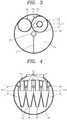
- FIG. 4is a sectional view taken along the line B-B' of FIG. 2 .
- the second cyclone 120may include an introduction pipe 121, a fine dust discharge pipe 125, and an air discharge pipe 128.
- An inlet 122is formed at an end portion of the introduction pipe 121 of the second cyclone 120. Air flowed through the mesh filter 115 is introduced into the introduction pipe 121 through the inlet 122.
- the introduction pipe 121may be formed in a cylindrical shape such that the air can orbit therein.
- the fine dust discharge pipe 125is formed in a shape of a conic pipe of getting narrower in a discharging direction of the fine dust. Accordingly, the fine dust may be separated from the air and discharged through the fine dust discharge pipe 125.
- the air discharge pipe 128is a pipe for externally discharging air from which the fine dust has been separated by the second cyclone 120, and may be formed in a cylindrical shape.
- the second cyclone 120may be provided in plurality.
- the plurality of second cyclones 120may extend in parallel with one another, and have a structure of being laminated (stacked) into plural layers.
- FIG. 2exemplarily illustrates the arrangement of the plurality of second cyclones 120 that four of the plurality of second cyclones 120 extend in parallel at a lower layer and three of the second cyclones 120 extend in parallel at an upper layer.
- the second cyclone 120has the fine dust discharge pipe 125 with the structure of getting narrower and is provided in plurality, thereby implementing a structure of more effectively separating and discharging the fine dust.
- FIG. 5is a conceptual view illustrating the dust collector 100 of FIG. 1 with the lower cover 150 open
- FIG. 6is a sectional view taken along the line C-C' of FIG. 5 . Description will be given with reference to FIGS. 5 and 6 .
- a user of the vacuum cleaneropens the lower cover 150 and discharges the collected dust to the outside.
- the lower cover 150is coupled to the first dust storing unit 130 by the hinge 157, so as to be open in a manner of rotating centering on the hinge 157. In response to the lower cover 150 being open, dust stuck on the mesh filter 115 of the first cyclone 110 and dust collected in the first and second dust storing units 130 and 140 may be externally discharged.
- the lower cover 150forms the bottom surface of the first cyclone 110 and the first and second dust storing units 130 and 140, the dust stuck on the mesh filter 115 of the first cyclone 110 and the dust collected in the first and second dust storing units 130 and 140 may be discharged out of the dust collector at once merely by opening the lower cover 150.
- the dust collector 100has the advantage in view of discharging dust collected therein at once, compared with the related art dust collector, in which the first cyclone or the first or second dust storing unit should be individually separated from the dust collector or a cover of the first cyclone or the first or second dust storing unit should be individually open to externally discharging dust collected in the dust collector.
- FIG. 7is a conceptual view illustrating the flow of air or dust in the first cyclone 110 and the second cyclones 120
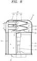
- FIG. 8is a conceptual view illustrating the flow of air or dust passing through the second cyclones 120.
- the vacuum cleanersucks external air containing foreign materials through a suction part 310 of the vacuum cleaner during a cleaning operation.
- the sucked airis introduced into a lower portion of the first cyclone 110 through a lower introduction pipe 15.
- the air introduced into the first cyclone 110flows upward with performing an orbiting motion.
- the foreign materialssuch as hairs, large dust and the like, are stuck (entangled) on the mesh filter 115 or collected into the first dust storing unit 130 by being discharged through the cutoff portion 113 of the first cyclone 110 with failing to pass through the mesh filter 115.
- Some of the fine dust and the airflow through an upper portion of the mesh filter 115 to be introduced into the introduction pipe 121 of the second cyclone 120 through the inlet 122 via the space of the upper surface of the first cyclone 110.
- the air introduced into the second cyclone 120orbits. During the orbiting motion, the fine dust is discharged through the fine dust discharge pipe 125 of the second cyclone 120, and the air is discharged through the air discharge pipe 128.
- the fine dust discharged through the fine dust discharge pipe 125flows along the guide surface 143 to be collected into the second dust storing unit 140.
- the guide surface 143may extend from an upper surface of the first dust storing unit 130 toward the second dust storing unit 140 in an inclined manner, such that the fine dust is guided along the second dust storing unit 140.
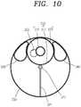
- FIG. 9is a disassembled conceptual view of a part of a dust collector 200 for a vacuum cleaner in accordance with another exemplary embodiment disclosed herein, and FIG. 10 is a sectional view taken along the line D-D' of FIG. 9 .
- the dust collector 200 for the vacuum cleanerincludes two second dust storing units 240.
- Each of the second dust storing units 240is disposed to come in contact with an outer circumferential surface of a first cyclone 210 and an inner circumferential surface of a first dust storing unit 230, respectively.
- the first cyclone 210is arranged in a center portion of the dust collector 200, whereas the two second dust storing units 240 are located between the first cyclone 210 and the inner circumferential surface of the first dust storing unit 230, respectively or adjacent to the first cyclone 210 and the inner circumferential surface of the first dust storing unit 230.
- Guide surfaces 243may extend from an upper surface of the first dust storing unit 230 toward both of the second dust storing units 240, respectively, in an inclined manner, such that fine dust can be guided along both of the second dust storing units 240.
- a cutoff portion 213 of the first cyclone 210should be spaced apart from the second dust storing units 240 by a predetermined gap so as to avoid the contact with the second dust storing units 240, such that dust can be smoothly discharged from the first cyclone 210 to the first dust storing unit 230.
- a lower cover 250should form a bottom surface of the first dust storing unit 230, the first cyclone 210 and the plurality of second dust storing units 240.
- the configurations and operation effects of the first dust storing unit 230, a mesh filter 215, a second cyclone 220 and the like of the dust collector 200 for the vacuum cleaner according to the another exemplary embodimentare the same/like as those aforementioned in association with the dust collector 100 according to the one exemplary embodiment.
- FIG. 11is a conceptual view of a vacuum cleaner 300 having the dust collector 100 according to the one exemplary embodiment disclosed herein.
- a main body 320is provided with a motor generating a rotational force, and a suction part 310 sucks air containing dust.
- the dust collector 100is configured to separate the dust from the air introduced from the suction part and discharge the separated dust.
- the dust collector 100has been aforementioned in detail, so description thereof will be omitted.
Landscapes
- Engineering & Computer Science (AREA)
- Mechanical Engineering (AREA)
- Chemical & Material Sciences (AREA)
- Chemical Kinetics & Catalysis (AREA)
- Filters For Electric Vacuum Cleaners (AREA)
Description
- This specification relates to a dust collector for a vacuum cleaner, capable of separating and collecting dust from air introduced into the vacuum cleaner and easily discharging the collected dust through a multi-cyclonic method.
- In general, a dust collector is an apparatus for collecting dust, such as hairs, dirt, and the like, contained in air using a cyclonic principle, and generally applied to vacuum cleaners.
- To improve dust collecting efficiency, a multi-cyclone dust collector having a plurality of cyclones connected is used in recent time.
- Typically, the multi-cyclone dust collector includes an upstream cyclone and a downstream cyclone that is connected to the upstream cyclone and collects relatively small dust. Also, the downstream cyclone is often provided with a plurality of small cyclones.
- Hereinafter, description will be given of a cyclone dust collector for a vacuum cleaner according to the related art.
- The cyclone dust collector includes a first cyclone that primarily collects dust by sucking external polluted air, and a second cyclone that is connected to the first cyclone and secondarily collects fine dust. In a multi-cyclone type, the second cyclone is a set of a plurality of small cyclones.
- The second cyclone corresponding to the plurality of small cyclones is installed along an outer circumference of the first cyclone. A first inlet through which external polluted air is introduced in a tangential direction is provided on a top of a first body of the first cyclone. A first outlet through which the air with the dust primarily separated therefrom is discharged toward the second cyclone is located approximately at a center in the first body of the first cyclone. The first outlet is typically formed in a cylindrical shape and has a structure with a lower portion open and an upper portion closed. In some cases, a filter is installed at the lower opening.
- Meanwhile, the second cyclone corresponds to the plurality of small cyclones which are located along the outer circumference of the first cyclone. Of course, each second cyclone (i.e., each small cyclone) has a second inlet and a second outlet. Typically, a buffering space is defined between the first cyclone and the second cyclones, such that air drawn out of the first cyclone is introduced into the second cyclones via the buffering space. Also, a discharge space which communicates with the second outlets of the plurality of second cyclones is located at an upper part of the second cyclones. The air is externally discharged through a discharge pipe via the discharge space.
- An operation of the related art multi-cyclone dust collector will now be described.
- When a suction force generating element, for example, a suction fan of a vacuum cleaner is driven in response to an activation of the multi-cyclone dust collector, external polluted air is introduced into the first cyclone through the first inlet of the first cyclone. Here, the polluted air is introduced in a tangential direction, and orbits along an inner wall surface of the first body of the first cyclone. During the orbiting motion, dust is separated from the air by a centrifugal force.
- Here, relatively heavy, large dust is collected on a bottom of the first cyclone, and small dust without being separated flows up while orbiting in the first cyclone and then is discharged through the first outlet.
- Meanwhile, air containing fine dust, discharged from the first cyclone, is introduced into the second cyclones through the second inlets. Therefore, the fine dust is separated from the air again in the second cyclones, such that purified air is discharged to the outside sequentially through the second outlets, the discharge space and the discharge pipe.
- However, the related art dust collector for the vacuum cleaner has the following problems.
- When a filter is provided in the first cyclone, large dust, such as hairs, foreign materials and the like, has to be primarily filtered out by the filter and separated, and fine dust and air have to be introduced into the second cyclones through the filter. Afterwards, the fine dust is separated from the air in the second cyclones.
- However, the large dust is stuck on the filter of the first cyclone and accordingly the filter fails to filter out and collect some of the large dust. Also, the dust stuck on the filter interferes with the flow of the fine dust. Consequently, the large dust and the fine dust are stuck and entangled on the filter.
- Even when discharging dust by opening a cover of the dust collector, such dust stuck and entangled on the filter is uneasy to be separated from the filter. Also, the large dust stuck on the filter interferes with the flow of air, lowering overall efficiency of the vacuum cleaner.
- Also, to externally discharge dust collected in the dust container, the first cyclone or a first or second dust storing unit should be individually detached from the dust collector, or a cover of the first cyclone or the first or second dust storing unit should be individually open. As a result, several processes are required for discharging the dust.
- In
EP 2 201 880 A2 a vacuum cleaner having a detachable dust separating unit is disclosed. The vacuum cleaner includes a cleaner body having a first opening - to open a portion of a first surface thereof and a second opening to open a portion of a second surface thereof, a dust separating unit to separate a dust from an air, and a seating part formed in the cleaner body to detachably mount the dust separating unit on the cleaner body. The dust separating unit forms a portion of an outward appearance of the cleaner body while closing up the first and the second openings of the cleaner body when the dust separating unit is mounted on the seating part.Further state of the art is known from
EP 1 952 744 A1 ,US 2007/0084160 A1 ,US 2008/0023036 A1 andUS 2010/0205915 A1 . - Therefore, to solve those problems of the related art, an aspect of the detailed description is to provide a structure for efficiently separating dust stuck on a filter of a first cyclone.
- To achieve these and other advantages and in accordance with the purpose of this specification, as embodied and broadly described herein, there is provided a dust collector for a vacuum cleaner including a first cyclone that is provided in a first dust storing unit, and configured to primarily separate dust from air introduced from a lower portion thereof with containing foreign materials and discharge the separated dust into the first dust storing unit, a second cyclone that is provided above the first cyclone to extend in an intersecting direction with an extending direction of the first cyclone, and configured to secondarily separate fine dust from the air introduced from the first cyclone and discharge the separated fine dust into a second dust storing unit, and a lower cover that defines a bottom surface of the first dust storing unit, the second dust storing unit and the first cyclone. Preferably the lower cover is coupled to the first dust storing unit by a hinge such that the foreign materials collected in the first dust storing unit, the second dust storing unit and the first cyclone are discharged upon being open.
- In accordance with one exemplary embodiment disclosed herein, the first cyclone may include a mesh filter that is configured to separate the dust from the air in a filtering manner.
- An upper portion of the mesh filter may be connected to an inlet of the second cyclone such that air passed through the mesh filter is introduced into the second cyclone.
- The mesh filter may be formed in a conic shape of getting narrower from top to bottom thereof, such that the dust filtered by the mesh filter and stuck on the mesh filter is separated from the mesh filter.
- The mesh filter may be provided in the first cyclone and extend substantially in the same direction as the extending direction of the first cyclone.
- In accordance with another exemplary embodiment disclosed herein, the second dust storing unit may be provided in the first dust storing unit, and further include a guide surface that is formed inclined to guide fine dust separated from the air by the second cyclone into the second dust storing unit.
- In accordance with another exemplary embodiment disclosed herein, the second dust storing unit may be provided in the first dust storing unit and extend substantially in the same direction as the extending direction of the first dust storing unit.
- The second dust storing unit may be formed in a cylindrical shape and disposed to come in contact with an outer circumferential surface of the first cyclone and an inner circumferential surface of the first dust storing unit.
- The second dust storing unit may be provided by two. The two second dust storing units may be arranged to come in contact with an outer circumferential surface of the first cyclone and an inner circumferential surface of the first dust storing unit, respectively.
- In accordance with another exemplary embodiment disclosed herein, the second cyclone may be provided in plurality. The plurality of second cyclones may extend in parallel with one another.
- The plurality of second cyclones may be laminated into plural layers.
- To achieve these and other advantages and in accordance with the purpose of this specification, as embodied and broadly described herein, there is provided a vacuum cleaner, including a main body that is provided with a motor generating a rotational force, a suction part that is configured to suck air containing dust, and a dust collector that is configured to separate the dust from the air introduced from the suction part and discharge the separated dust, wherein the dust collector may include a first cyclone that is provided in a first dust storing unit, and configured to primarily separate dust from air introduced from a lower portion thereof with containing foreign materials and discharge the separated dust into the first dust storing unit, a second cyclone that is provided above the first cyclone to extend in an intersecting direction with an extending direction of the first cyclone, and configured to secondarily separate fine dust from the air introduced from the first cyclone and discharge the separated fine dust into a second dust storing unit, and a lower cover that defines a bottom surface of the first dust storing unit, the second dust storing unit and the first cyclone, and coupled to the first dust storing unit by a hinge such that the foreign materials collected in the first dust storing unit, the second dust storing unit and the first cyclone are discharged upon being open.
- A dust collector according to one exemplary embodiment disclosed herein may be provided with a lower cover defining a bottom surface of a first cyclone, and first and second dust storing units. This may allow for discharging dust collected in the first cyclone and the first and second dust storing units at once when the lower cover is open.
- A dust collector according to another exemplary embodiment disclosed herein may be provided with a mesh filter which is provided in a first cyclone and has a conic shape of getting narrower from top to bottom thereof. This may allow for more efficiently separating and discharging large dust stuck on the mesh filter.
- Preferably, the first dust storing unit may have a transparent portion.
- In a further preferred embodiment the dust collector may comprise an upper casing covering the upper portion of the second cyclone being connected to the first dust storing unit.
- Preferably, the first dust storing unit has a cylindrical shape, which is covered at its bottom side with the lower cover.
- Further scope of applicability of the present application will become more apparent from the detailed description given hereinafter. However, it should be understood that the detailed description and specific examples, while indicating preferred embodiments of the disclosure, are given by way of illustration only, since various changes and modifications within the scope of the disclosure will become apparent to those skilled in the art from the detailed description.
- The accompanying drawings, which are included to provide a further understanding of the disclosure and are incorporated in and constitute a part of this specification, illustrate exemplary embodiments and together with the description serve to explain the principles of the disclosure.
- In the drawings:
FIG. 1 is a perspective view of a dust collector for a vacuum cleaner in accordance with one exemplary embodiment disclosed herein;FIG. 2 is a conceptual view illustrating a part of the dust collector ofFIG. 1 in a disassembled state;FIG. 3 is a sectional view taken along the line A-A' ofFIG. 2 ;FIG. 4 is a sectional view taken along the line B-B' ofFIG. 2 ;FIG. 5 is a conceptual view illustrating the dust collector ofFIG. 1 with a lower cover open;FIG. 6 is a sectional view taken along the line C-C' ofFIG. 5 ;FIG. 7 is a conceptual view illustrating the flow of air or dust in a first cyclone and a second cyclone;FIG. 8 is a conceptual view illustrating the flow of air or dust passing through the second cyclone;FIG. 9 is a disassembled conceptual view of a part of a dust collector for a vacuum cleaner in accordance with another exemplary embodiment disclosed herein;FIG. 10 is a sectional view taken along the line D-D' ofFIG. 9 ; andFIG. 11 is a conceptual view of a vacuum cleaner having the dust collector according to the one exemplary embodiment disclosed herein.- Description will now be given in detail of the exemplary embodiments disclosed herein to facilitate for the practice of those person skilled in the art to which the present disclosure belongs, with reference to the accompanying drawings. The present disclosure will be realized in different configurations, without being limited to those exemplary embodiments disclosed herein.
- For the sake of brief description with reference to the drawings, the same or equivalent components will be provided with the same reference numbers, and description thereof will not be repeated. A singular representation may include a plural representation unless it represents a definitely different meaning from the context.
FIG. 1 is a perspective view of adust collector 100 for a vacuum cleaner in accordance with one exemplary embodiment disclosed herein,FIG. 2 is a conceptual view illustrating a part of thedust collector 100 ofFIG. 1 in a disassembled state, andFIG. 3 is a sectional view taken along the line A-A' ofFIG. 2 .- As illustrated in
FIGS. 1 to 3 , thedust collector 100 for the vacuum cleaner may include afirst cyclone 110, asecond cyclone 120, a firstdust storing unit 130, a seconddust storing unit 140, and alower cover 150. - The
first cyclone 110 may primarily separate dust from air, which is introduced along with foreign materials through anintroduction opening 153 formed through a bottom surface thereof, and discharge the separated dust into the firstdust storing unit 130. Thefirst cyclone 110 may include ahousing 111 and amesh filter 115. - The
housing 111 of thefirst cyclone 110 may be located within the firstdust storing unit 130. Thehousing 111 may be formed in a cylindrical shape such that dust can be separated and discharged from air using a centrifugal force. - For example, the
housing 111 of thefirst cyclone 110 may extend substantially in the same direction as an extending direction of the firstdust storing unit 130, so as to form an appearance of thefirst cyclone 110. Thehousing 111 may allow air or dust introduced through a lower part thereof to orbit therein. Most suited is a substantial upright orientation of the first dust storing unit during operation. - Also, a
cutoff portion 113 may further be formed at an upper part of thehousing 111, such that large dust can be discharged from thefirst cyclone 110 to the firstdust storing unit 130 therethrough. - The
mesh filter 115 filters out the large dust from the introduced air. - In order for the air passed through the
mesh filter 115 to flow up into anintroduction pipe 121 of thesecond cyclone 120 to be explained later, an upper portion of themesh filter 115 is connected to theintroduction pipe 121 of thesecond cyclone 120 through a space of an upper surface of thefirst cyclone 110. - The
mesh filter 115 may be formed in a manner of extending substantially in the same direction as the extending direction of thefirst cyclone 110, and may be formed in a conic shape of getting narrower from top to bottom thereof. The structure of themesh filter 115 may more facilitate dust, which is stuck on themesh filter 115, to be separated from themesh filter 115 when opening thelower cover 150. - The first
dust storing unit 130 may be configured such that the large dust discharged from thefirst cyclone 110 is collected therein. Also, the firstdust storing unit 130 has a structure of accommodating therein thefirst cyclone 110, the seconddust storing unit 140 and acompression plate 171. - The first
dust storing unit 130 may be formed in a cylindrical shape, which may define a part of the appearance of thedust collector 100. A casing (not illustrated) may further be provided at an outside of the firstdust storing unit 130 so as to define the part of the appearance of thedust collector 100. The firstdust storing unit 130 or the casing (not illustrated) may be formed transparent such that an amount of dust collected in the firstdust storing unit 130 is visible. - The
compression plate 171 for compressing dust may be rotatably provided in the firstdust storing unit 130. Thecompression plate 171 may compress the dust collected in the firstdust storing unit 130. Accordingly, an increased space may be ensured in the firstdust storing unit 130 and thus more dust may be collected. - The
compression plate 171 may compress dust by rotating in one direction centering on acentral shaft 173. When its rotation in the one direction is interrupted due to foreign materials or large dust during the rotation, thecompression plate 171 may switch the rotating direction to rotate in a reverse direction. - The
second cyclone 120 secondarily separates fine dust from the air, which has been introduced sequentially through the upper portion of themesh filter 115 and aninlet 122, and discharges the separated fine dust. The discharged fine dust is collected into the seconddust storing unit 140 along aguide surface 143. - The
second cyclone 120 is located above thefirst cyclone 110 and extends in an intersecting direction with the extending direction of thefirst cyclone 110. For example, thesecond cyclone 120 may extend horizontal to a bottom surface of thefirst cyclone 110. - The
first cyclone 110 is arranged to have a substantially vertical orientation, whereas thesecond cyclone 120 is arranged to have a substantially horizontal orientation. - To prevent the fine dust, which has been separated and discharged from the
second cyclone 120, from being scattered to outside, a finedust discharge opening 126 is formed at an end portion of the finedust discharge pipe 125 to provide the fine dust to the seconddust storing unit 140. - The
upper casing 160 may be coupled to the firstdust storing unit 130 or a lower casing (not illustrated) of the firstdust storing unit 130. A detailed structure of thesecond cyclone 120 will be explained later. - The second
dust storing unit 140 is configured such that the fine dust discharged from thesecond cyclone 120 is collected therein. The seconddust storing unit 140 may be formed in a cylindrical shape. In addition to the cylindrical shape, the seconddust storing unit 140 may have various shapes suitable for collecting the fine dust therein. - The second
dust storing unit 140 includes aguide surface 143 which is inclined downwardly. Theguide surface 143 guides the fine dust separated from the air by thesecond cyclone 120 to be collected in the seconddust storing unit 140. - The
lower cover 150 defines the bottom surface of the firstdust storing unit 130, the seconddust storing unit 140 and thefirst cyclone 110. Thelower cover 150 may be coupled to the firstdust storing unit 130 by a coupling means, like ahinge 157 or clamp so as to open and close the firstdust storing unit 130. For example, thelower cover 150 may be formed in a shape of a thin plate, or be implemented into various shapes suitable for closing the bottom surface of the firstdust storing unit 130, the seconddust storing unit 140 and the like. - The
lower cover 150 may be provided with a plurality of sealingmembers dust storing unit 130, the seconddust storing unit 140 and thefirst cyclone 110. An introduction opening 153 may be formed through the bottom surface of thelower cover 150 of thefirst cyclone 110 at a location of the first cyclone. External air containing dust and foreign materials may be introduced into thefirst cyclone 110 through theintroduction opening 153. FIG. 4 is a sectional view taken along the line B-B' ofFIG. 2 .- Hereinafter, a structure of the
second cyclone 120 will be described with reference toFIGS. 2 and4 . - The
second cyclone 120 may include anintroduction pipe 121, a finedust discharge pipe 125, and anair discharge pipe 128. - An
inlet 122 is formed at an end portion of theintroduction pipe 121 of thesecond cyclone 120. Air flowed through themesh filter 115 is introduced into theintroduction pipe 121 through theinlet 122. Theintroduction pipe 121 may be formed in a cylindrical shape such that the air can orbit therein. - The fine
dust discharge pipe 125 is formed in a shape of a conic pipe of getting narrower in a discharging direction of the fine dust. Accordingly, the fine dust may be separated from the air and discharged through the finedust discharge pipe 125. - The
air discharge pipe 128 is a pipe for externally discharging air from which the fine dust has been separated by thesecond cyclone 120, and may be formed in a cylindrical shape. - The
second cyclone 120 may be provided in plurality. The plurality ofsecond cyclones 120 may extend in parallel with one another, and have a structure of being laminated (stacked) into plural layers.FIG. 2 exemplarily illustrates the arrangement of the plurality ofsecond cyclones 120 that four of the plurality ofsecond cyclones 120 extend in parallel at a lower layer and three of thesecond cyclones 120 extend in parallel at an upper layer. - The
second cyclone 120 has the finedust discharge pipe 125 with the structure of getting narrower and is provided in plurality, thereby implementing a structure of more effectively separating and discharging the fine dust. FIG. 5 is a conceptual view illustrating thedust collector 100 ofFIG. 1 with thelower cover 150 open, andFIG. 6 is a sectional view taken along the line C-C' ofFIG. 5 . Description will be given with reference toFIGS. 5 and6 .- When a predetermined amount of dust is collected in the
first cyclone 110 and the first and seconddust storing units lower cover 150 and discharges the collected dust to the outside. - The
lower cover 150 is coupled to the firstdust storing unit 130 by thehinge 157, so as to be open in a manner of rotating centering on thehinge 157. In response to thelower cover 150 being open, dust stuck on themesh filter 115 of thefirst cyclone 110 and dust collected in the first and seconddust storing units - As aforementioned, since the
lower cover 150 forms the bottom surface of thefirst cyclone 110 and the first and seconddust storing units mesh filter 115 of thefirst cyclone 110 and the dust collected in the first and seconddust storing units lower cover 150. - Therefore, the
dust collector 100 according to the one exemplary embodiment disclosed herein has the advantage in view of discharging dust collected therein at once, compared with the related art dust collector, in which the first cyclone or the first or second dust storing unit should be individually separated from the dust collector or a cover of the first cyclone or the first or second dust storing unit should be individually open to externally discharging dust collected in the dust collector. FIG. 7 is a conceptual view illustrating the flow of air or dust in thefirst cyclone 110 and thesecond cyclones 120, andFIG. 8 is a conceptual view illustrating the flow of air or dust passing through thesecond cyclones 120.- Hereinafter, description will be given of a process in which external air containing foreign materials is introduced into the
dust collector 100 and dust and fine dust are separated from the air, with reference toFIGS. 7 and8 . - The vacuum cleaner sucks external air containing foreign materials through a
suction part 310 of the vacuum cleaner during a cleaning operation. The sucked air is introduced into a lower portion of thefirst cyclone 110 through alower introduction pipe 15. The air introduced into thefirst cyclone 110 flows upward with performing an orbiting motion. During this process, the foreign materials, such as hairs, large dust and the like, are stuck (entangled) on themesh filter 115 or collected into the firstdust storing unit 130 by being discharged through thecutoff portion 113 of thefirst cyclone 110 with failing to pass through themesh filter 115. - Some of the fine dust and the air flow through an upper portion of the
mesh filter 115 to be introduced into theintroduction pipe 121 of thesecond cyclone 120 through theinlet 122 via the space of the upper surface of thefirst cyclone 110. The air introduced into thesecond cyclone 120 orbits. During the orbiting motion, the fine dust is discharged through the finedust discharge pipe 125 of thesecond cyclone 120, and the air is discharged through theair discharge pipe 128. - The fine dust discharged through the fine
dust discharge pipe 125 flows along theguide surface 143 to be collected into the seconddust storing unit 140. Theguide surface 143 may extend from an upper surface of the firstdust storing unit 130 toward the seconddust storing unit 140 in an inclined manner, such that the fine dust is guided along the seconddust storing unit 140. FIG. 9 is a disassembled conceptual view of a part of adust collector 200 for a vacuum cleaner in accordance with another exemplary embodiment disclosed herein, andFIG. 10 is a sectional view taken along the line D-D' ofFIG. 9 .- As illustrated in
FIGS. 9 and10 , thedust collector 200 for the vacuum cleaner according to the another exemplary embodiment disclosed herein includes two seconddust storing units 240. Each of the seconddust storing units 240 is disposed to come in contact with an outer circumferential surface of afirst cyclone 210 and an inner circumferential surface of a firstdust storing unit 230, respectively. With other words, thefirst cyclone 210 is arranged in a center portion of thedust collector 200, whereas the two seconddust storing units 240 are located between thefirst cyclone 210 and the inner circumferential surface of the firstdust storing unit 230, respectively or adjacent to thefirst cyclone 210 and the inner circumferential surface of the firstdust storing unit 230. - Guide surfaces 243 may extend from an upper surface of the first
dust storing unit 230 toward both of the seconddust storing units 240, respectively, in an inclined manner, such that fine dust can be guided along both of the seconddust storing units 240. - A
cutoff portion 213 of thefirst cyclone 210 should be spaced apart from the seconddust storing units 240 by a predetermined gap so as to avoid the contact with the seconddust storing units 240, such that dust can be smoothly discharged from thefirst cyclone 210 to the firstdust storing unit 230. - Meanwhile, a
lower cover 250 should form a bottom surface of the firstdust storing unit 230, thefirst cyclone 210 and the plurality of seconddust storing units 240. - The configurations and operation effects of the first
dust storing unit 230, amesh filter 215, asecond cyclone 220 and the like of thedust collector 200 for the vacuum cleaner according to the another exemplary embodiment are the same/like as those aforementioned in association with thedust collector 100 according to the one exemplary embodiment. FIG. 11 is a conceptual view of avacuum cleaner 300 having thedust collector 100 according to the one exemplary embodiment disclosed herein.- A
main body 320 is provided with a motor generating a rotational force, and asuction part 310 sucks air containing dust. Thedust collector 100 is configured to separate the dust from the air introduced from the suction part and discharge the separated dust. Thedust collector 100 has been aforementioned in detail, so description thereof will be omitted. - The configurations and methods of the dust collector for the vacuum cleaner in the aforesaid embodiments may not be limitedly applied, but such embodiments may be configured by a selective combination of all or part of the embodiments so as to implement many variations.
- As the present features may be embodied in several forms without departing from the characteristics thereof, it should also be understood that the above-described embodiments are not limited by any of the details of the foregoing description, unless otherwise specified, but rather should be construed broadly within its scope as defined in the appended claims, and therefore all changes and modifications that fall within the metes and bounds of the claims, or equivalents of such metes and bounds are therefore intended to be embraced by the appended claims.
Claims (15)
- A dust collector (100, 200) for a vacuum cleaner comprising:a first cyclone (110, 210) that is provided in a first dust storing unit (130, 230), and configured to primarily separate dust from air introduced from a lower portion thereof with containing foreign materials and discharge the separated dust into the first dust storing unit (130);a second cyclone (120, 220) that is provided above the first cyclone (110, 210) to extend in an intersecting direction with an extending direction of the first cyclone (110, 210), and configured to secondarily separate fine dust from the air introduced from the first cyclone (110, 210) and discharge the separated fine dust into a second dust storing unit (140, 240); anda lower cover (150, 250) that defines a bottom surface of the first dust storing unit (130, 230), the second dust storing unit (140, 240) and the first cyclone (110, 210),characterized in that:the lower cover (150, 250) is coupled to the first dust storing unit (130, 230) by a hinge (157, 257) and is opened in a manner of rotating centering on the hinge (157, 257) such that the foreign materials collected in the first dust storing unit (130, 230), the second dust storing unit (140, 240) and the first cyclone (110, 210) are discharged at once when the lower cover (150, 250) is open.
- The dust collector of claim 1, wherein the first dust storing unit (130, 230) is accommodating the second dust storing unit (140, 240) and the first cyclone (110, 210).
- The dust collector according to any one of the preceding claims, wherein the first dust storing unit (130, 230) and the second dust storing unit (140, 240) extend in the same direction and have their bottoms in the same layer.
- The dust collector according to any one of the preceding claims, wherein the first cyclone (110, 210) comprises a mesh filter (115, 215) that is configured to separate the dust from the air in a filtering manner.
- The dust collector of claim 4, wherein an upper portion of the mesh filter (115, 215) is connected to an inlet (122) of the second cyclone (120, 220) such that air passed through the mesh filter (115, 215) is introduced into the second cyclone (120, 220).
- The dust collector of claim 4 or 5 , wherein the mesh filter (115, 215) is formed in a conic shape of getting narrower from top to bottom thereof, such that the dust filtered by the mesh filter (115, 215) and stuck on the mesh filter (115, 215) is separated from the mesh filter (115, 215) upon being open.
- The dust collector according to any one of the preceding claims 4-6, wherein the mesh filter (115, 215) is provided in the first cyclone (110, 210) and extends substantially in the same direction as the extending direction of the first cyclone (110, 210).
- The dust collector according to any one of the preceding claims, wherein the second dust storing unit (140, 240) is provided in the first dust storing unit (130, 230), and comprises a guide surface (143, 243) that is formed inclined to guide fine dust separated from the air by the second cyclone (120, 220) into the second dust storing unit (140, 240).
- The dust collector according to any one of the preceding claims, wherein the second dust storing unit (140, 240) is provided in the first dust storing unit (130, 230) and extends substantially in the same direction as the extending direction of the first dust storing unit (130, 230).
- The dust collector according to any one of the preceding claims, wherein the second dust storing unit (140, 240) is formed in a cylindrical shape and is in contact with an outer circumferential surface of the first cyclone (110, 210) and an inner circumferential surface of the first dust storing unit (130, 230).
- The dust collector according to any one of the preceding claims, wherein two second dust storing units (240) are provided, the two second dust storing units (240) are arranged to come in contact with an outer circumferential surface of the first cyclone (210) and an inner circumferential surface of the first dust storing unit (230), respectively.
- The dust collector according to any one of the preceding claims, wherein a plurality of second cyclones (140, 240) is provided, the plurality of second cyclones (140, 240) extend in parallel with one another.
- The dust collector of claim 12, wherein the plurality of second cyclones (140, 240) are arranged in a plurality of layers.
- The dust collector according to any one of the preceding claims, further comprising a compression plate (171, 271), that is rotated centering on a central shaft (173, 273) to compress dust in the first dust storing unit (130, 230).
- A vacuum cleaner comprising:a main body (320) that is provided with a motor generating a rotational force;a suction part (310) that is configured to suck air containing dust; anda dust collector (100, 200) that is configured to separate the dust from the air introduced from the suction part (310) and discharge the separated dust according to any one of the preceding claims 1-14.
Applications Claiming Priority (1)
| Application Number | Priority Date | Filing Date | Title |
|---|---|---|---|
| KR1020140130428AKR101622724B1 (en) | 2014-09-29 | 2014-09-29 | Dust collector for a vacuum cleaner |
Publications (2)
| Publication Number | Publication Date |
|---|---|
| EP3000371A1 EP3000371A1 (en) | 2016-03-30 |
| EP3000371B1true EP3000371B1 (en) | 2018-05-16 |
Family
ID=52598662
Family Applications (1)
| Application Number | Title | Priority Date | Filing Date |
|---|---|---|---|
| EP15157817.6AActiveEP3000371B1 (en) | 2014-09-29 | 2015-03-05 | Dust collector for vacuum cleaner |
Country Status (3)
| Country | Link |
|---|---|
| US (1) | US9808134B2 (en) |
| EP (1) | EP3000371B1 (en) |
| KR (1) | KR101622724B1 (en) |
Cited By (2)
| Publication number | Priority date | Publication date | Assignee | Title |
|---|---|---|---|---|
| EP3685725B1 (en)* | 2017-09-22 | 2022-11-30 | LG Electronics Inc. | Dust collecting apparatus and cleaner having same |
| EP3685726B1 (en)* | 2017-09-22 | 2022-11-30 | LG Electronics Inc. | Dust collecting apparatus and cleaner having same |
Families Citing this family (16)
| Publication number | Priority date | Publication date | Assignee | Title |
|---|---|---|---|---|
| KR101653459B1 (en)* | 2014-12-01 | 2016-09-01 | 엘지전자 주식회사 | Vacuum clenar and dust collecting apparatus |
| KR101653481B1 (en) | 2015-01-16 | 2016-09-01 | 엘지전자 주식회사 | Vacuum cleaner and dust collecting apparatus |
| US20190217404A1 (en)* | 2015-08-31 | 2019-07-18 | JPL Global, LLC | Circular saw apparatus with integrated multistage filtration system |
| DE102016120311B4 (en)* | 2016-10-25 | 2023-03-30 | Robert Thomas Metall- Und Elektrowerke Gmbh & Co. Kg | Vacuum cleaner |
| US10966583B2 (en)* | 2019-01-23 | 2021-04-06 | Omachron Intellectual Property Inc. | Surface cleaning apparatus, cyclonic air treatment member and surface cleaning apparatus including the same |
| US11219906B2 (en) | 2019-01-23 | 2022-01-11 | Omachron Intellectual Property Inc. | Surface cleaning apparatus, cyclonic air treatment member and surface cleaning apparatus including the same |
| US11980334B2 (en) | 2017-09-15 | 2024-05-14 | Omachron Intellectual Property Inc. | Surface cleaning apparatus |
| CN107581974B (en)* | 2017-10-18 | 2023-08-01 | 莱克电气股份有限公司 | Dust cup with double-spiral dust-gas separation structure |
| CA3116593A1 (en) | 2018-10-22 | 2020-04-30 | Omachron Intellectual Property Inc. | Air treatment apparatus |
| US11129510B2 (en)* | 2019-01-23 | 2021-09-28 | Omachron Intellectual Property Inc. | Surface cleaning apparatus, cyclonic air treatment member and surface cleaning apparatus including the same |
| US10925451B2 (en)* | 2019-01-23 | 2021-02-23 | Omachron Intellectual Property Inc. | Surface cleaning apparatus, cyclonic air treatment member and surface cleaning apparatus including the same |
| US11135602B2 (en)* | 2019-01-23 | 2021-10-05 | Omachron Intellectual Property Inc. | Surface cleaning apparatus, cyclonic air treatment member and surface cleaning apparatus including the same |
| US11213832B2 (en)* | 2019-01-23 | 2022-01-04 | Omachron Intellectual Property Inc. | Surface cleaning apparatus, cyclonic air treatment member and surface cleaning apparatus including the same |
| US10974258B2 (en)* | 2019-01-23 | 2021-04-13 | Omachron Intellectual Property Inc. | Surface cleaning apparatus, cyclonic air treatment member and surface cleaning apparatus including the same |
| WO2020186342A1 (en) | 2019-03-15 | 2020-09-24 | Omachron Intellectual Property Inc. | Surface cleaning apparatus |
| JP1740121S (en)* | 2022-02-18 | 2023-03-28 | vacuum cleaner body |
Family Cites Families (19)
| Publication number | Priority date | Publication date | Assignee | Title |
|---|---|---|---|---|
| KR101148125B1 (en)* | 2005-01-07 | 2012-05-23 | 삼성전자주식회사 | Cyclonic Cleaner |
| KR100672483B1 (en) | 2005-06-28 | 2007-01-24 | 엘지전자 주식회사 | Dust collector of vacuum cleaner |
| KR100630952B1 (en)* | 2005-10-11 | 2006-10-04 | 삼성광주전자 주식회사 | Multi cyclone dust collector for vacuum cleaner and vacuum cleaner having same |
| KR100688613B1 (en)* | 2005-10-11 | 2007-03-02 | 삼성광주전자 주식회사 | Multi Cyclone Dust Collector for Vacuum Cleaner |
| KR100714493B1 (en)* | 2005-10-14 | 2007-05-07 | 삼성광주전자 주식회사 | Dust collector of vacuum cleaner |
| KR100725514B1 (en)* | 2005-10-19 | 2007-06-08 | 삼성광주전자 주식회사 | Multi Cyclone Dust Collector for Vacuum Cleaner |
| US8544143B2 (en)* | 2005-12-10 | 2013-10-01 | Lg Electronics Inc. | Vacuum cleaner with removable dust collector, and methods of operating the same |
| US7749295B2 (en)* | 2005-12-10 | 2010-07-06 | Lg Electronics Inc. | Vacuum cleaner with removable dust collector, and methods of operating the same |
| US8012250B2 (en)* | 2005-12-10 | 2011-09-06 | Lg Electronics Inc. | Vacuum cleaner |
| EP1949842B1 (en)* | 2007-01-24 | 2015-03-04 | LG Electronics Inc. | Vacuum cleaner |
| KR100783143B1 (en)* | 2007-02-05 | 2007-12-07 | 삼성광주전자 주식회사 | Cyclone Dust Collector for Vacuum Cleaner |
| KR100992221B1 (en)* | 2008-05-16 | 2010-11-05 | 엘지전자 주식회사 | Vacuum cleaner |
| KR101542185B1 (en)* | 2008-12-29 | 2015-08-07 | 삼성전자주식회사 | Vacuum cleaner having detachable dust-separating dpparatus |
| US8528163B2 (en)* | 2009-02-12 | 2013-09-10 | Lg Electronics Inc. | Vacuum cleaner |
| US8282697B2 (en)* | 2009-02-16 | 2012-10-09 | Samsung Electronics Co., Ltd. | Dust collecting apparatus for vacuum cleaner |
| US8151409B2 (en)* | 2009-02-26 | 2012-04-10 | Lg Electronics Inc. | Vacuum cleaner |
| JP4856271B2 (en) | 2010-10-25 | 2012-01-18 | シャープ株式会社 | Cyclone separator |
| DE112012000251B4 (en)* | 2011-02-18 | 2018-04-12 | Techtronic Floor Care Technology Ltd. | Dust container for vacuum cleaners |
| GB2508035B (en)* | 2012-11-20 | 2015-03-11 | Dyson Technology Ltd | Cleaning appliance |
- 2014
- 2014-09-29KRKR1020140130428Apatent/KR101622724B1/enactiveActive
- 2015
- 2015-03-05EPEP15157817.6Apatent/EP3000371B1/enactiveActive
- 2015-03-09USUS14/642,179patent/US9808134B2/enactiveActive
Non-Patent Citations (1)
| Title |
|---|
| None* |
Cited By (2)
| Publication number | Priority date | Publication date | Assignee | Title |
|---|---|---|---|---|
| EP3685725B1 (en)* | 2017-09-22 | 2022-11-30 | LG Electronics Inc. | Dust collecting apparatus and cleaner having same |
| EP3685726B1 (en)* | 2017-09-22 | 2022-11-30 | LG Electronics Inc. | Dust collecting apparatus and cleaner having same |
Also Published As
| Publication number | Publication date |
|---|---|
| US20160088989A1 (en) | 2016-03-31 |
| KR101622724B1 (en) | 2016-05-19 |
| KR20160037617A (en) | 2016-04-06 |
| US9808134B2 (en) | 2017-11-07 |
| EP3000371A1 (en) | 2016-03-30 |
Similar Documents
| Publication | Publication Date | Title |
|---|---|---|
| EP3000371B1 (en) | Dust collector for vacuum cleaner | |
| US10925452B2 (en) | Dust collector for vacuum cleaner | |
| CN105530847B (en) | Dust collect plant and electric dust collector | |
| CN1839744B (en) | Cyclone dust separating apparatus for vacuum cleaner and the vacuum cleaner | |
| US7547337B2 (en) | Multi dust-collecting apparatus | |
| RU2328961C1 (en) | Vacuum cleaner (option) | |
| US10492652B2 (en) | Dust collector for vacuum cleaner | |
| US9955837B2 (en) | Dust collector for vacuum cleaner | |
| KR101990832B1 (en) | Dust separating apparatus and vacuum cleaner having the same | |
| EP3653096B1 (en) | Vacuum cleaner | |
| CN101803893A (en) | Dust collection device for vacuum cleaner | |
| US10537220B2 (en) | Cyclone dust collector and vacuum cleaner having the same | |
| US10028630B2 (en) | Cleaner | |
| EP3998006A1 (en) | Vacuum cleaner | |
| EP3005924B1 (en) | Dust collector for vacuum cleaner | |
| EP1676514A2 (en) | Vacuum cleaner | |
| KR20070000633A (en) | Dust collector of vacuum cleaner | |
| KR100606795B1 (en) | Multi Cyclone Dust Collector | |
| KR100565581B1 (en) | Cyclone Dust Collector for Vacuum Cleaner | |
| KR100988382B1 (en) | Dust separator of vacuum cleaner | |
| KR20100020641A (en) | Vacuum cleaner for scattering prevention of dust |
Legal Events
| Date | Code | Title | Description |
|---|---|---|---|
| PUAI | Public reference made under article 153(3) epc to a published international application that has entered the european phase | Free format text:ORIGINAL CODE: 0009012 | |
| AK | Designated contracting states | Kind code of ref document:A1 Designated state(s):AL AT BE BG CH CY CZ DE DK EE ES FI FR GB GR HR HU IE IS IT LI LT LU LV MC MK MT NL NO PL PT RO RS SE SI SK SM TR | |
| AX | Request for extension of the european patent | Extension state:BA ME | |
| 17P | Request for examination filed | Effective date:20160830 | |
| RBV | Designated contracting states (corrected) | Designated state(s):AL AT BE BG CH CY CZ DE DK EE ES FI FR GB GR HR HU IE IS IT LI LT LU LV MC MK MT NL NO PL PT RO RS SE SI SK SM TR | |
| GRAP | Despatch of communication of intention to grant a patent | Free format text:ORIGINAL CODE: EPIDOSNIGR1 | |
| STAA | Information on the status of an ep patent application or granted ep patent | Free format text:STATUS: GRANT OF PATENT IS INTENDED | |
| INTG | Intention to grant announced | Effective date:20180108 | |
| RAP1 | Party data changed (applicant data changed or rights of an application transferred) | Owner name:LG ELECTRONICS INC. | |
| GRAS | Grant fee paid | Free format text:ORIGINAL CODE: EPIDOSNIGR3 | |
| GRAA | (expected) grant | Free format text:ORIGINAL CODE: 0009210 | |
| STAA | Information on the status of an ep patent application or granted ep patent | Free format text:STATUS: THE PATENT HAS BEEN GRANTED | |
| AK | Designated contracting states | Kind code of ref document:B1 Designated state(s):AL AT BE BG CH CY CZ DE DK EE ES FI FR GB GR HR HU IE IS IT LI LT LU LV MC MK MT NL NO PL PT RO RS SE SI SK SM TR | |
| REG | Reference to a national code | Ref country code:GB Ref legal event code:FG4D | |
| REG | Reference to a national code | Ref country code:CH Ref legal event code:EP | |
| REG | Reference to a national code | Ref country code:IE Ref legal event code:FG4D | |
| REG | Reference to a national code | Ref country code:DE Ref legal event code:R096 Ref document number:602015011073 Country of ref document:DE | |
| REG | Reference to a national code | Ref country code:AT Ref legal event code:REF Ref document number:998781 Country of ref document:AT Kind code of ref document:T Effective date:20180615 | |
| REG | Reference to a national code | Ref country code:NL Ref legal event code:MP Effective date:20180516 | |
| REG | Reference to a national code | Ref country code:LT Ref legal event code:MG4D | |
| PG25 | Lapsed in a contracting state [announced via postgrant information from national office to epo] | Ref country code:SE Free format text:LAPSE BECAUSE OF FAILURE TO SUBMIT A TRANSLATION OF THE DESCRIPTION OR TO PAY THE FEE WITHIN THE PRESCRIBED TIME-LIMIT Effective date:20180516 Ref country code:FI Free format text:LAPSE BECAUSE OF FAILURE TO SUBMIT A TRANSLATION OF THE DESCRIPTION OR TO PAY THE FEE WITHIN THE PRESCRIBED TIME-LIMIT Effective date:20180516 Ref country code:BG Free format text:LAPSE BECAUSE OF FAILURE TO SUBMIT A TRANSLATION OF THE DESCRIPTION OR TO PAY THE FEE WITHIN THE PRESCRIBED TIME-LIMIT Effective date:20180816 Ref country code:NO Free format text:LAPSE BECAUSE OF FAILURE TO SUBMIT A TRANSLATION OF THE DESCRIPTION OR TO PAY THE FEE WITHIN THE PRESCRIBED TIME-LIMIT Effective date:20180816 Ref country code:LT Free format text:LAPSE BECAUSE OF FAILURE TO SUBMIT A TRANSLATION OF THE DESCRIPTION OR TO PAY THE FEE WITHIN THE PRESCRIBED TIME-LIMIT Effective date:20180516 Ref country code:ES Free format text:LAPSE BECAUSE OF FAILURE TO SUBMIT A TRANSLATION OF THE DESCRIPTION OR TO PAY THE FEE WITHIN THE PRESCRIBED TIME-LIMIT Effective date:20180516 | |
| PG25 | Lapsed in a contracting state [announced via postgrant information from national office to epo] | Ref country code:GR Free format text:LAPSE BECAUSE OF FAILURE TO SUBMIT A TRANSLATION OF THE DESCRIPTION OR TO PAY THE FEE WITHIN THE PRESCRIBED TIME-LIMIT Effective date:20180817 Ref country code:HR Free format text:LAPSE BECAUSE OF FAILURE TO SUBMIT A TRANSLATION OF THE DESCRIPTION OR TO PAY THE FEE WITHIN THE PRESCRIBED TIME-LIMIT Effective date:20180516 Ref country code:RS Free format text:LAPSE BECAUSE OF FAILURE TO SUBMIT A TRANSLATION OF THE DESCRIPTION OR TO PAY THE FEE WITHIN THE PRESCRIBED TIME-LIMIT Effective date:20180516 Ref country code:LV Free format text:LAPSE BECAUSE OF FAILURE TO SUBMIT A TRANSLATION OF THE DESCRIPTION OR TO PAY THE FEE WITHIN THE PRESCRIBED TIME-LIMIT Effective date:20180516 Ref country code:NL Free format text:LAPSE BECAUSE OF FAILURE TO SUBMIT A TRANSLATION OF THE DESCRIPTION OR TO PAY THE FEE WITHIN THE PRESCRIBED TIME-LIMIT Effective date:20180516 | |
| REG | Reference to a national code | Ref country code:AT Ref legal event code:MK05 Ref document number:998781 Country of ref document:AT Kind code of ref document:T Effective date:20180516 | |
| PG25 | Lapsed in a contracting state [announced via postgrant information from national office to epo] | Ref country code:AT Free format text:LAPSE BECAUSE OF FAILURE TO SUBMIT A TRANSLATION OF THE DESCRIPTION OR TO PAY THE FEE WITHIN THE PRESCRIBED TIME-LIMIT Effective date:20180516 Ref country code:RO Free format text:LAPSE BECAUSE OF FAILURE TO SUBMIT A TRANSLATION OF THE DESCRIPTION OR TO PAY THE FEE WITHIN THE PRESCRIBED TIME-LIMIT Effective date:20180516 Ref country code:CZ Free format text:LAPSE BECAUSE OF FAILURE TO SUBMIT A TRANSLATION OF THE DESCRIPTION OR TO PAY THE FEE WITHIN THE PRESCRIBED TIME-LIMIT Effective date:20180516 Ref country code:PL Free format text:LAPSE BECAUSE OF FAILURE TO SUBMIT A TRANSLATION OF THE DESCRIPTION OR TO PAY THE FEE WITHIN THE PRESCRIBED TIME-LIMIT Effective date:20180516 Ref country code:EE Free format text:LAPSE BECAUSE OF FAILURE TO SUBMIT A TRANSLATION OF THE DESCRIPTION OR TO PAY THE FEE WITHIN THE PRESCRIBED TIME-LIMIT Effective date:20180516 Ref country code:DK Free format text:LAPSE BECAUSE OF FAILURE TO SUBMIT A TRANSLATION OF THE DESCRIPTION OR TO PAY THE FEE WITHIN THE PRESCRIBED TIME-LIMIT Effective date:20180516 Ref country code:SK Free format text:LAPSE BECAUSE OF FAILURE TO SUBMIT A TRANSLATION OF THE DESCRIPTION OR TO PAY THE FEE WITHIN THE PRESCRIBED TIME-LIMIT Effective date:20180516 | |
| REG | Reference to a national code | Ref country code:DE Ref legal event code:R097 Ref document number:602015011073 Country of ref document:DE | |
| PG25 | Lapsed in a contracting state [announced via postgrant information from national office to epo] | Ref country code:IT Free format text:LAPSE BECAUSE OF FAILURE TO SUBMIT A TRANSLATION OF THE DESCRIPTION OR TO PAY THE FEE WITHIN THE PRESCRIBED TIME-LIMIT Effective date:20180516 Ref country code:SM Free format text:LAPSE BECAUSE OF FAILURE TO SUBMIT A TRANSLATION OF THE DESCRIPTION OR TO PAY THE FEE WITHIN THE PRESCRIBED TIME-LIMIT Effective date:20180516 | |
| PLBE | No opposition filed within time limit | Free format text:ORIGINAL CODE: 0009261 | |
| STAA | Information on the status of an ep patent application or granted ep patent | Free format text:STATUS: NO OPPOSITION FILED WITHIN TIME LIMIT | |
| 26N | No opposition filed | Effective date:20190219 | |
| PG25 | Lapsed in a contracting state [announced via postgrant information from national office to epo] | Ref country code:SI Free format text:LAPSE BECAUSE OF FAILURE TO SUBMIT A TRANSLATION OF THE DESCRIPTION OR TO PAY THE FEE WITHIN THE PRESCRIBED TIME-LIMIT Effective date:20180516 | |
| PG25 | Lapsed in a contracting state [announced via postgrant information from national office to epo] | Ref country code:MC Free format text:LAPSE BECAUSE OF FAILURE TO SUBMIT A TRANSLATION OF THE DESCRIPTION OR TO PAY THE FEE WITHIN THE PRESCRIBED TIME-LIMIT Effective date:20180516 | |
| REG | Reference to a national code | Ref country code:CH Ref legal event code:PL | |
| PG25 | Lapsed in a contracting state [announced via postgrant information from national office to epo] | Ref country code:AL Free format text:LAPSE BECAUSE OF FAILURE TO SUBMIT A TRANSLATION OF THE DESCRIPTION OR TO PAY THE FEE WITHIN THE PRESCRIBED TIME-LIMIT Effective date:20180516 Ref country code:LU Free format text:LAPSE BECAUSE OF NON-PAYMENT OF DUE FEES Effective date:20190305 | |
| REG | Reference to a national code | Ref country code:BE Ref legal event code:MM Effective date:20190331 | |
| PG25 | Lapsed in a contracting state [announced via postgrant information from national office to epo] | Ref country code:LI Free format text:LAPSE BECAUSE OF NON-PAYMENT OF DUE FEES Effective date:20190331 Ref country code:IE Free format text:LAPSE BECAUSE OF NON-PAYMENT OF DUE FEES Effective date:20190305 Ref country code:CH Free format text:LAPSE BECAUSE OF NON-PAYMENT OF DUE FEES Effective date:20190331 | |
| PG25 | Lapsed in a contracting state [announced via postgrant information from national office to epo] | Ref country code:BE Free format text:LAPSE BECAUSE OF NON-PAYMENT OF DUE FEES Effective date:20190331 Ref country code:FR Free format text:LAPSE BECAUSE OF NON-PAYMENT OF DUE FEES Effective date:20190331 | |
| PG25 | Lapsed in a contracting state [announced via postgrant information from national office to epo] | Ref country code:TR Free format text:LAPSE BECAUSE OF FAILURE TO SUBMIT A TRANSLATION OF THE DESCRIPTION OR TO PAY THE FEE WITHIN THE PRESCRIBED TIME-LIMIT Effective date:20180516 | |
| PG25 | Lapsed in a contracting state [announced via postgrant information from national office to epo] | Ref country code:MT Free format text:LAPSE BECAUSE OF NON-PAYMENT OF DUE FEES Effective date:20190305 Ref country code:PT Free format text:LAPSE BECAUSE OF FAILURE TO SUBMIT A TRANSLATION OF THE DESCRIPTION OR TO PAY THE FEE WITHIN THE PRESCRIBED TIME-LIMIT Effective date:20180917 | |
| PG25 | Lapsed in a contracting state [announced via postgrant information from national office to epo] | Ref country code:CY Free format text:LAPSE BECAUSE OF FAILURE TO SUBMIT A TRANSLATION OF THE DESCRIPTION OR TO PAY THE FEE WITHIN THE PRESCRIBED TIME-LIMIT Effective date:20180516 | |
| PG25 | Lapsed in a contracting state [announced via postgrant information from national office to epo] | Ref country code:IS Free format text:LAPSE BECAUSE OF FAILURE TO SUBMIT A TRANSLATION OF THE DESCRIPTION OR TO PAY THE FEE WITHIN THE PRESCRIBED TIME-LIMIT Effective date:20180916 | |
| PG25 | Lapsed in a contracting state [announced via postgrant information from national office to epo] | Ref country code:HU Free format text:LAPSE BECAUSE OF FAILURE TO SUBMIT A TRANSLATION OF THE DESCRIPTION OR TO PAY THE FEE WITHIN THE PRESCRIBED TIME-LIMIT; INVALID AB INITIO Effective date:20150305 | |
| PG25 | Lapsed in a contracting state [announced via postgrant information from national office to epo] | Ref country code:MK Free format text:LAPSE BECAUSE OF FAILURE TO SUBMIT A TRANSLATION OF THE DESCRIPTION OR TO PAY THE FEE WITHIN THE PRESCRIBED TIME-LIMIT Effective date:20180516 | |
| PGFP | Annual fee paid to national office [announced via postgrant information from national office to epo] | Ref country code:GB Payment date:20240205 Year of fee payment:10 | |
| PGFP | Annual fee paid to national office [announced via postgrant information from national office to epo] | Ref country code:DE Payment date:20250205 Year of fee payment:11 |